US7087075B2 - Feedback system for rapid induction of mild hypothermia - Google Patents
Feedback system for rapid induction of mild hypothermiaDownload PDFInfo
- Publication number
- US7087075B2 US7087075B2US10/262,680US26268002AUS7087075B2US 7087075 B2US7087075 B2US 7087075B2US 26268002 AUS26268002 AUS 26268002AUS 7087075 B2US7087075 B2US 7087075B2
- Authority
- US
- United States
- Prior art keywords
- coolant
- patient
- carrier gas
- cooling
- sensor
- Prior art date
- Legal status (The legal status is an assumption and is not a legal conclusion. Google has not performed a legal analysis and makes no representation as to the accuracy of the status listed.)
- Expired - Lifetime, expires
Links
Images


Classifications
- A—HUMAN NECESSITIES
- A61—MEDICAL OR VETERINARY SCIENCE; HYGIENE
- A61F—FILTERS IMPLANTABLE INTO BLOOD VESSELS; PROSTHESES; DEVICES PROVIDING PATENCY TO, OR PREVENTING COLLAPSING OF, TUBULAR STRUCTURES OF THE BODY, e.g. STENTS; ORTHOPAEDIC, NURSING OR CONTRACEPTIVE DEVICES; FOMENTATION; TREATMENT OR PROTECTION OF EYES OR EARS; BANDAGES, DRESSINGS OR ABSORBENT PADS; FIRST-AID KITS
- A61F7/00—Heating or cooling appliances for medical or therapeutic treatment of the human body
- A61F7/02—Compresses or poultices for effecting heating or cooling
- G—PHYSICS
- G05—CONTROLLING; REGULATING
- G05D—SYSTEMS FOR CONTROLLING OR REGULATING NON-ELECTRIC VARIABLES
- G05D23/00—Control of temperature
- G05D23/19—Control of temperature characterised by the use of electric means
- G05D23/1919—Control of temperature characterised by the use of electric means characterised by the type of controller
- G—PHYSICS
- G05—CONTROLLING; REGULATING
- G05D—SYSTEMS FOR CONTROLLING OR REGULATING NON-ELECTRIC VARIABLES
- G05D23/00—Control of temperature
- G05D23/19—Control of temperature characterised by the use of electric means
- G05D23/1925—Control of temperature characterised by the use of electric means using a combination of auxiliary electric and non-electric power
- G—PHYSICS
- G05—CONTROLLING; REGULATING
- G05D—SYSTEMS FOR CONTROLLING OR REGULATING NON-ELECTRIC VARIABLES
- G05D23/00—Control of temperature
- G05D23/19—Control of temperature characterised by the use of electric means
- G05D23/1927—Control of temperature characterised by the use of electric means using a plurality of sensors
- G05D23/193—Control of temperature characterised by the use of electric means using a plurality of sensors sensing the temperaure in different places in thermal relationship with one or more spaces
- G05D23/1931—Control of temperature characterised by the use of electric means using a plurality of sensors sensing the temperaure in different places in thermal relationship with one or more spaces to control the temperature of one space
- A—HUMAN NECESSITIES
- A61—MEDICAL OR VETERINARY SCIENCE; HYGIENE
- A61B—DIAGNOSIS; SURGERY; IDENTIFICATION
- A61B17/00—Surgical instruments, devices or methods
- A61B2017/00017—Electrical control of surgical instruments
- A61B2017/00022—Sensing or detecting at the treatment site
- A61B2017/00084—Temperature
- A—HUMAN NECESSITIES
- A61—MEDICAL OR VETERINARY SCIENCE; HYGIENE
- A61B—DIAGNOSIS; SURGERY; IDENTIFICATION
- A61B5/00—Measuring for diagnostic purposes; Identification of persons
- A61B5/02—Detecting, measuring or recording for evaluating the cardiovascular system, e.g. pulse, heart rate, blood pressure or blood flow
- A61B5/0205—Simultaneously evaluating both cardiovascular conditions and different types of body conditions, e.g. heart and respiratory condition
- A61B5/02055—Simultaneously evaluating both cardiovascular condition and temperature
- A—HUMAN NECESSITIES
- A61—MEDICAL OR VETERINARY SCIENCE; HYGIENE
- A61F—FILTERS IMPLANTABLE INTO BLOOD VESSELS; PROSTHESES; DEVICES PROVIDING PATENCY TO, OR PREVENTING COLLAPSING OF, TUBULAR STRUCTURES OF THE BODY, e.g. STENTS; ORTHOPAEDIC, NURSING OR CONTRACEPTIVE DEVICES; FOMENTATION; TREATMENT OR PROTECTION OF EYES OR EARS; BANDAGES, DRESSINGS OR ABSORBENT PADS; FIRST-AID KITS
- A61F7/00—Heating or cooling appliances for medical or therapeutic treatment of the human body
- A61F2007/0001—Body part
- A—HUMAN NECESSITIES
- A61—MEDICAL OR VETERINARY SCIENCE; HYGIENE
- A61F—FILTERS IMPLANTABLE INTO BLOOD VESSELS; PROSTHESES; DEVICES PROVIDING PATENCY TO, OR PREVENTING COLLAPSING OF, TUBULAR STRUCTURES OF THE BODY, e.g. STENTS; ORTHOPAEDIC, NURSING OR CONTRACEPTIVE DEVICES; FOMENTATION; TREATMENT OR PROTECTION OF EYES OR EARS; BANDAGES, DRESSINGS OR ABSORBENT PADS; FIRST-AID KITS
- A61F7/00—Heating or cooling appliances for medical or therapeutic treatment of the human body
- A61F2007/0054—Heating or cooling appliances for medical or therapeutic treatment of the human body with a closed fluid circuit, e.g. hot water
- A61F2007/0056—Heating or cooling appliances for medical or therapeutic treatment of the human body with a closed fluid circuit, e.g. hot water for cooling
- A61F2007/0057—Heating or cooling appliances for medical or therapeutic treatment of the human body with a closed fluid circuit, e.g. hot water for cooling of gas, e.g. air or carbon dioxide
- A—HUMAN NECESSITIES
- A61—MEDICAL OR VETERINARY SCIENCE; HYGIENE
- A61F—FILTERS IMPLANTABLE INTO BLOOD VESSELS; PROSTHESES; DEVICES PROVIDING PATENCY TO, OR PREVENTING COLLAPSING OF, TUBULAR STRUCTURES OF THE BODY, e.g. STENTS; ORTHOPAEDIC, NURSING OR CONTRACEPTIVE DEVICES; FOMENTATION; TREATMENT OR PROTECTION OF EYES OR EARS; BANDAGES, DRESSINGS OR ABSORBENT PADS; FIRST-AID KITS
- A61F7/00—Heating or cooling appliances for medical or therapeutic treatment of the human body
- A61F2007/0059—Heating or cooling appliances for medical or therapeutic treatment of the human body with an open fluid circuit
- A61F2007/0063—Heating or cooling appliances for medical or therapeutic treatment of the human body with an open fluid circuit for cooling
- A—HUMAN NECESSITIES
- A61—MEDICAL OR VETERINARY SCIENCE; HYGIENE
- A61F—FILTERS IMPLANTABLE INTO BLOOD VESSELS; PROSTHESES; DEVICES PROVIDING PATENCY TO, OR PREVENTING COLLAPSING OF, TUBULAR STRUCTURES OF THE BODY, e.g. STENTS; ORTHOPAEDIC, NURSING OR CONTRACEPTIVE DEVICES; FOMENTATION; TREATMENT OR PROTECTION OF EYES OR EARS; BANDAGES, DRESSINGS OR ABSORBENT PADS; FIRST-AID KITS
- A61F7/00—Heating or cooling appliances for medical or therapeutic treatment of the human body
- A61F7/02—Compresses or poultices for effecting heating or cooling
- A61F2007/0225—Compresses or poultices for effecting heating or cooling connected to the body or a part thereof
- A61F2007/0233—Compresses or poultices for effecting heating or cooling connected to the body or a part thereof connected to or incorporated in clothing or garments
- A—HUMAN NECESSITIES
- A61—MEDICAL OR VETERINARY SCIENCE; HYGIENE
- A61F—FILTERS IMPLANTABLE INTO BLOOD VESSELS; PROSTHESES; DEVICES PROVIDING PATENCY TO, OR PREVENTING COLLAPSING OF, TUBULAR STRUCTURES OF THE BODY, e.g. STENTS; ORTHOPAEDIC, NURSING OR CONTRACEPTIVE DEVICES; FOMENTATION; TREATMENT OR PROTECTION OF EYES OR EARS; BANDAGES, DRESSINGS OR ABSORBENT PADS; FIRST-AID KITS
- A61F7/00—Heating or cooling appliances for medical or therapeutic treatment of the human body
- A61F7/02—Compresses or poultices for effecting heating or cooling
- A61F2007/0244—Compresses or poultices for effecting heating or cooling with layers
- A61F2007/026—Compresses or poultices for effecting heating or cooling with layers with a fluid absorbing layer
- A—HUMAN NECESSITIES
- A62—LIFE-SAVING; FIRE-FIGHTING
- A62B—DEVICES, APPARATUS OR METHODS FOR LIFE-SAVING
- A62B17/00—Protective clothing affording protection against heat or harmful chemical agents or for use at high altitudes
- A62B17/005—Active or passive body temperature control
Definitions
- the inventionrelates to medical devices that control the temperature of a patient, and more particularly, to feedback systems for medical devices that control the temperature of a patient.
- hypothermiaSome medical conditions may be treated by hypothermia.
- hypothermic therapy within the first few minutes of the onset of a conditionmay mean the difference between life and death.
- prompt hypothermic therapymay make a dramatic difference in the quality of life of the patient.
- Strokeis an example of a medical condition that may be treated by prompt administration of hypothermic therapy.
- Many patients that suffer strokesdie as a result of the stroke, and a significant fraction of those who survive suffer some degree of neurological damage.
- the neurological damage to the patientmay be slowed by the application of hypothermic therapy.
- hypothermiathere have been many different techniques studied to produce hypothermia in the body, including invasive and non-invasive techniques, such as the use of cold packs, ice blankets, injecting a cooled saline solution into the blood stream, heating the hypothalamus, cooling the air around the patient, and circulating of a coolant fluid around the patient.
- Some techniquesare more effective than others. Many of these techniques involve bulky apparatuses that are difficult to transport to the patient, and are usually available only in a hospital setting. In addition, many of these techniques rely upon the training of specially skilled hospital personnel. There may be a significant delay in administration of hypothermic therapy while the patient is being taken to the hospital.
- a feedback systemmay control a cooling garment in response to a signal from the sensor.
- the sensormay be placed within the cooling garment, and may generate a signal as a function of a patient parameter such as body temperature, and/or heart rate.
- the cooling garmentmay include sensors within more than one of the garments.
- a cooling garmentmay contain more than one sensor.
- a controllermay receive signals from the sensors via a communication bundle. The controller may compare the signals received from the sensors with target values input by a user, usually emergency medical personnel or a doctor. When the received signals are outside of an appropriate operating range, the controller may send a regulation signal to a regulator.
- the regulatormay adjust delivery of one or more of a coolant, a carrier gas, and/or a warm air supply to the cooling garment. For instance, the regulator may adjust the pressure of the coolant, the temperature of the coolant, the flow rate of the coolant, and/or the mixing ratio of the coolant. The regulator may also adjust the delivery of the carrier gas and the warm air supply concurrently with the coolant.
- the inventionis directed to a system that comprises a cooling garment that contacts a portion of the body of a patient.
- the cooling garmentdelivers a coolant and a carrier gas to the body of the patient.
- the systemfurther comprises a controller for controlling the cooling garment in response to a signal from a sensor.
- the inventionpresents a method comprising delivering a carrier gas and a coolant to a cooling garment in contact with the body of a patient.
- the methodfurther comprises generating a signal that measures a parameter of the body of the patient.
- the methodalso includes controlling the cooling garment in response to the generated signal.
- the inventionpresents a system that comprises a coolant supply that supplies coolant to a cooling garment that contacts a portion of a body of a patient.
- the systemalso comprises a carrier gas supply that supplies carrier gas to the cooling garment.
- the systemincludes a warm air supply that supplies warm air to a body part of the patient.
- the systemalso includes a regulator that regulates at least one of the coolant supply, the carrier gas supply and the warm air supply as a function of a patient parameter.
- the inventionmay provide numerous advantages.
- the feedback systemmay provide for a safe yet rapid lowering of the temperature of the patient, by continuously monitoring the condition of the patient. Should the patient be at risk of frostbite, for example, the system may automatically perform adjustments to reduce that risk.
- the systemmay respond to conditions other than temperature, and may regulate therapy as a function of those conditions. The system may further alert a health care professional of life-threatening conditions, such as a serious arrhythmia or cardiac arrest.
- the feedback systemmay regulate one or more cooling garments simultaneously.
- Each garmentmay be regulated individually for enhanced effect. Regulation of multiple garments allows the garments to work together in concert.
- the feedback systemis versatile and can be customized to the needs of each patient.
- a usermay program the system to supply appropriate therapy for the patient.
- FIG. 1is a schematic diagram illustrating a front view of an exemplary headgear used for cooling of a patient, according to an embodiment of the invention.
- FIG. 2is a schematic diagram illustrating a front view of an embodiment the headgear shown in FIG. 1 .
- FIG. 3is a schematic diagram illustrating a split cross-sectional profile of the exemplary headgear of FIG. 2 .
- FIG. 4is a flow diagram illustrating the cooling process occurring inside the headgear of FIG. 2 .
- FIG. 5is a schematic diagram illustrating a cross-sectional view of another embodiment of the headgear of FIG. 1 .
- FIG. 6is a schematic diagram illustrating a front view of an exemplary upper body gear used for cooling of a patient, according to an embodiment of the invention.
- FIG. 7is a schematic diagram illustrating a front view of another exemplary upper body gear used for cooling of a patient, according to an embodiment of the invention.
- FIG. 8is a schematic diagram illustrating a front view of another exemplary upper body gear used for cooling of a patient, according to an embodiment of the invention.
- FIG. 9is a schematic diagram illustrating a front view of an exemplary lower body gear used for cooling of a patient, according to an embodiment of the invention.
- FIG. 10is a schematic diagram illustrating a cross-sectional view of a body gear, according to an embodiment of the invention.
- FIG. 11is a schematic diagram illustrating a cooling system used to cool a patient, according to an embodiment of the invention.
- FIG. 12is a schematic diagram illustrating an exemplary cooling feedback system, according to an embodiment of the invention.
- FIG. 13is a block diagram illustrating the cooling feedback system of FIG. 12 .
- FIG. 14is a flowchart illustrating the interaction of various feedback components of the cooling feedback system of FIG. 13 to control the cooling process of patient.
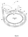
- FIG. 1is a schematic front view of an exemplary headgear 10 used for cooling of a patient 12 .
- Headgear 10is one embodiment of a cooling garment.
- Headgear 10comprises a deformable enclosure member 14 .
- Enclosure member 14deforms so that enclosure member 14 may be placed upon the head of patient 12 .
- Enclosure member 14includes one or more spacers (not shown) that separate at least a portion of enclosure member 14 from the body of patient 12 defining a space.
- a spacermay be coupled to headgear 10 .
- a spacermay detach from headgear 10 .
- enclosure member 14may be held in place with fasteners 16 A and 16 B (collectively fasteners 16 ), allowing a user, such as emergency medical personnel to administer other treatments to patient 12 .
- Fastener 16 Aadjusts just above face 20 and fastener 16 B adjusts under chin 22 , so as to fit around different size heads.
- Securing fasteners 16causes seal members 17 A and 17 B (collectively seal members 17 ) to contact the body of patient 12 , substantially isolating the space inside enclosure member 14 from an exterior environment.
- Enclosure member 14may be formed from a substantially compliant material, such as rubber, plastic, or airtight cloth. Enclosure member 14 may have a different rigidity for an anterior portion as opposed to a posterior portion. For example, the posterior of enclosure member 14 may be more rigid in order to support the weight of patient 12 .
- Seal members 17may be formed from a pliable material such as rubber, plastic, or silicone, and may be sewn, bonded, or otherwise affixed to enclosure member 14 . Seal member 17 , for example, may be a flexible rubber web, an 0 -ring tube seal, a collapsible tube or the like.
- Fasteners 16may be any sort of fastening device such as a zipper, a hook and loon fastener such as VELCRO, a button, a clip, a buckle, a strap, an adhesive, or the like.
- Enclosure member 14may include an ear access 24 , which allows outside access to the ear of patient 12 when headgear 10 is in place on the head. The temperature of patient 12 may be measured through ear access 24 .
- Ear access 24may be embodied as an aperture in enclosure member 14 , an earflap, or the like. Enclosure member 14 may further include other body accesses that allow access to other portions of the head.
- Headgear 10further comprises a gas intake/outflow unit 26 .
- Gas intake/outflow unit 26may include a carrier gas intake port 28 that receives a carrier gas supply 30 .
- Gas intake/outflow unit 26may be substantially rigid, and may be formed from materials such as non-corrosive metal, plastic, or rubber.
- Gas intake/outflow unit 26 and, more particularly, carrier gas intake port 28fluidly connects the space between the head of patient 12 and enclosure member 14 to carrier gas supply 30 .
- gas intake/outflow unit 26receives a carrier gas from carrier gas supply 30 .
- a carrier gas mover(not shown) moves the carrier gas within the space. The operation of gas intake/outflow unit 26 will be described in more detail below.
- the carrier gasmay be carbon dioxide, nitrogen, air or the like.
- the carrier gasmay be a mixture of gases.
- the carrier gasmay be a mixture of carbon dioxide and air.
- airmay be mixed with the carbon dioxide to reduce the temperature of the carrier gas for the safety of the patient.
- Carrier gasessuch as carbon dioxide and nitrogen may be more effective than air in absorbing evaporated coolant, especially in an environment with high humidity.
- the carrier gasmay be a gas other than oxygen and non-reactive with oxygen.
- Headgear 10may further include a coolant port 34 that receives a coolant supply 36 .
- Coolant port 34brings coolant supply 36 into fluid communication with a coolant delivery conduit 38 .
- Coolant delivery conduit 38may branch at coolant port 34 into coolant delivery conduit branch 38 A and 38 B.
- Coolant delivery conduit branch 38 Amay carry a liquid coolant into headgear 10 , anteriorly to approximately under chin 22 , around left side of face 20 of patient 12 , and to the edge of fastener 16 A.
- Coolant delivery conduit branch 38 Bmay carry the liquid coolant posteriorly around neck 40 of patient 12 , then anteriorly to approximately under chin 22 , around right side of face 20 , and to the edge of fastener 16 A.
- coolant delivery conduit 38may extend from coolant port 34 posteriorly around neck 40 to approximately under chin 22 in both directions. Coolant delivery conduit 38 may proceed from chin 22 around face 20 and terminate at two sites proximate to fastener 16 A.
- the inventionencompasses coolant delivery conduit 38 branching in a fashion different than described above, or not branching at all.
- the pressure of the coolant in coolant delivery conduit 38may form a seal member 18 for the portions of headgear 10 around neck 40 and face 20 .
- coolant delivery conduit 38may transport coolant around the head and form a seal proximate to face 20 .
- Seal members 17create the seal at sites around face 20 where coolant delivery conduit 38 does not extend.
- coolant delivery conduit 38may not be a seal member, in which case seal members 17 may create the seal around face 20 .
- Coolant delivery conduit 38 and/or seal members 17may also be a spacer that creates the space between the patient and headgear 10 .
- Coolant delivery conduit 38may be flexibly formed from tube-like structures made of materials such as rubber, plastic, or the like. Coolant delivery conduit 38 may be shaped to expand and contract to accommodate heads of different sizes and shapes. Examples of construction of coolant delivery conduit 38 will be described in more detail below.
- Coolant supply 36is a tube-like structure, which may allow one-way or two-way flow of the coolant. Coolant supply 36 may be constructed of flexible tube-like structures made of materials such as rubber, plastic, silicone or the like. Coolant supply 36 may include a quick-connect coupling (not shown) that mates to coolant port 34 . In a typical application, coolant supply 36 may be coupled to coolant port 34 after headgear 10 is placed upon the head of patient 12 .
- Coolant delivery conduit 38may include small apertures (not shown) that allow the coolant to drip out, seep out, mist out, spray out, or otherwise exit the lumen of coolant delivery conduit 38 .
- the coolant that exits from coolant delivery conduit 38may be applied to the body of patient 12 .
- the coolant that exits coolant delivery conduit 38may be applied to an absorbent layer in contact with the body.
- the absorbent layerabsorbs the coolant and keeps the coolant in contact with the body.
- the absorbent layermay further prevent the coolant from pooling up in areas where gravity tends to pull the coolant.
- the absorbent layermay be constructed of material such as polypropylene, cotton, or the like.
- the coolantmay also be applied directly to the body of patient 12 .
- the inventionmay further include applying the liquid coolant inside the headgear in other fashions.
- the coolant that exits from coolant delivery conduit 38may also mix with the carrier gas from carrier gas supply 30 .
- Liquid coolantneed not come in direct contact with the body of patient 12 .
- the coolantis typically a liquid that evaporates due to the heat generated by the head of patient 12 or by a gas flowing over the coolant.
- Alcohol, water, or a mixture of alcohol and waterare examples of typical coolants.
- the coolantmay also be a gas or a gel.
- Liquid coolantsaccept heat and undergoes a state change to gaseous form. This heat of transformation can be substantial.
- the state change of the coolant inside of headgear 10draws body heat and thereby cools patient 12 .
- Coolant applied to the body of patient 12may draw body heat from direct contact of the coolant and patient 12 through this evaporation process.
- the coolant that is applied within headgear 10may draw body heat from direct contact of the coolant and patient 12 or from heat propagating outward from patient 12 by radiation or convection.
- Carrier gas and coolant in gaseous formare discharged through an exit port 41 located within gas intake/outflow unit 26 as will be described below, and fresh carrier gas and coolant replace what has been discharged.
- Headgear 10may include multiple coolant delivery conduits, multiple gas intake ports or both. Multiple conduits and intake ports may allow for localized cooling of portions of the head.
- headgear 10may include four cooling areas. Each cooling area may be served by a discrete coolant delivery conduit 38 and a gas intake port 28 . Alternatively, each cooling area may include a common coolant delivery conduit 38 and separate gas intake port 28 . The cooling areas may be separated from one another by one or more dividers that isolate the space of one cooling area from the space of neighboring cooling areas.
- the same coolant supply 36may supply coolant to each of the coolant delivery conduits. Alternatively, a separate coolant supply 36 may supply coolant to each of the coolant delivery conduits.
- Carrier gas intake ports 28may also be supplied by the same carrier gas supply or multiple carrier gas supplies.
- a housing 32may house a processor to process information that the processor receives from optical fiber links, a wireless link, wire link, and the like.
- the processormay receive information in the form of signals from one or more sensors on the body of patient 12 .
- Headgear 10may further comprise a battery pack 43 that operates headgear 10 when no AC power source is available.
- battery pack 43may power the processor at the location of a traumatic event.
- Battery pack 43may also power the carrier gas mover or any other electric or electronic components of headgear 10 .
- headgear 10may be powered by any source, including an alternating current (AC) power source and a direct current (DC) power source.
- ACalternating current
- DCdirect current
- FIG. 2is a schematic front view of an embodiment of headgear 10 of FIG. 1 .
- Headgear 10 Amay further comprise an outer shell 44 and an inner shell 46 .
- a set of inner spacers 48creates a separation between patient 12 and inner shell 46 , the separation between patient 12 and inner shell 46 referred to hereinafter as an inner space 50 .
- a set of outer spacers 51creates a separation between outer shell 44 and inner shell 46 , the separation outer shell 44 and inner shell 46 referred to hereinafter as an outer space 52 .
- Inner space 50is in fluid communication with outer space 52 .
- Inner shell 46may be constructed from a rigid to semi-rigid material such as a plastic, rubber or the like.
- Outer shell 44may be constructed from a rigid to semi-rigid material that is also electrically insulated such as plastic, rubber, or the like. Outer shell 44 may be constructed from a rigid to semi-rigid material that is also electrically insulated. Insulation of outer shell 44 may prevent interference with electrical equipment concurrently being used for treatment and monitoring of patient 12 .
- Inner spacers 48 and outer spacers 51may be constructed from materials such as plastic, rubber, or the like. Alternatively, spacers 48 and 51 may be a chain, air, or the like.
- Inner spacers 48may house within them at least one sensor 54 and a communication link 56 .
- Sensor 54generates a signal as a function of a patient parameter such as temperature, oxygen saturation levels, blood flow, heart rate, brain electrical action, end tidal carbon dioxide levels or the like.
- Communication link 56then relays the signal to a processor, which may be housed in housing 32 .
- Sensor 54may be an assortment of sensor devices such as a temperature sensor, a thermocouple, an oxygen sensor, a velocity Doppler probe, an electrocardiogram (ECG) sensor, an electroencephalograph (EEG) sensor, or the like.
- Communication link 56may include an optical fiber link, a wireless link, a wire link, or the like.
- Carrier gas entering headgear 10 A at carrier gas port 28enters outer space 52 in gas intake/outflow unit 26 .
- Carrier gasflows in outer space 52 from the crown of the head toward the neck, where carrier gas enters inner space 50 .
- Carrier gasflows in inner space 50 from the neck to the crown, exiting at exit port 41 in gas intake/outflow unit 26 .
- Gas intake/outflow unit 26may include a carrier gas mover, such as a fan 58 , that circulates carrier gas within headgear 10 A.
- Other carrier gas moverssuch as a pressurized carrier gas supply or a pump, may be used to move the carrier gas instead of or in addition to fan 58 .
- FIG. 3is a schematic diagram illustrating a split cross-sectional profile of exemplary headgear 10 A of FIG. 2 .
- the outer profile of headgear 10 Ais shown to the left of line 60 and the inner cross-sectional profile of headgear 10 A is shown to the right of line 60 .
- Headgear 10 Amay comprise a gas fitting 62 mated to carrier gas port 28 .
- Gas fitting 62may be a quick-connect coupling that mates carrier gas supply 30 to gas intake/outflow unit 26 .
- Headgear 10 Amay further comprise a coolant fitting 64 .
- Coolant fitting 64may be a quick-connect coupling that mates coolant supply 36 to coolant port 34 .
- Headgear 10 Amay also comprise expanders 66 A and 66 B (collectively expanders 66 ). Expanders 66 allow headgear 10 A to expand to accommodate different sizes and shapes of heads. As mentioned previously, the material of headgear 10 A may be more rigid posteriorly from expanders 66 to the back of the head of patient 12 than anteriorly from expanders 66 to the face 20 of patient 12 . Expanders 66 may be constructed from a material with the ability to stretch and contract, such as spandex, rubber, elastic or the like.
- Headgear 10 Amay further comprise a warm air supply 68 and a warm air nozzle 70 to blow warm air on face 20 of patient 12 .
- patient 12may shiver. Shivering generates heat and is counterproductive to the cooling process.
- Warm air applied via warm air nozzle 70 to face 20may reduce shivering.
- warm air supply 68 and warm air nozzle 70may be applied with enough pressure to blow coolant and carrier gas that may leak from headgear 10 A away from the eyes, nose, or mouth of patient 12 .
- Warm air supply 68may be made of a tube-like structure made of materials such as rubber, plastic, or the like.
- Warm air nozzle 70receives warm air from warm air supply 68 , and may spread the warm air to cover a substantial portion of face 20 .
- Headgear 10 Amay also comprise a support pad 72 to support the head of patient 12 . Since patient 12 will be lying for most of the monitoring and treatment procedures, support pad 72 will give patient 12 some level of comfort. Furthermore, support pad 72 may prevent wear to the backside of headgear 10 A from friction between the ground and headgear 10 A. Support pad 72 may be any type of padding such as a pillow, a cushion, and the like. Support pad 72 of FIG. 3 is shown as an extension from outer shell 44 . Alternatively, support pad 72 may be located within headgear 10 A, and may further be absorbent to collect excess coolant to prevent the coolant from pooling up in areas where gravity tends to pull the coolant, such as the back of the head and neck.
- the inner profile of headgear 10 Ashown to the right of line 60 , illustrates how headgear 10 A circulates carrier gas.
- Carrier gas supply 30is coupled to gas port 28 via gas fitting 62 .
- the carrier gas from carrier gas supply 30enters outer space 52 in gas intake/outflow unit 26 .
- Coolant supply 36is coupled to coolant port 34 via cooling fitting 64 .
- the coolant from coolant supply 36enters headgear 10 A and is carried by coolant delivery conduit 38 .
- Coolant delivery conduit 38branches proximate to coolant port 34 , and coolant delivery conduit branch 38 B carries coolant posteriorly around the neck.
- coolant delivery conduit branch 38 BA cross-section of coolant delivery conduit branch 38 B is shown in FIG. 3 .
- coolant delivery conduit 38has a pleated cross-section that allows coolant delivery conduit 38 to conform to different sizes of necks.
- Coolant delivery conduit 38may allow the coolant to drip out, mist out, seep out, spray out, or otherwise exit the lumen of cooling conduit 38 throughout the entire path of cooling conduit 38 .
- the coolantexits the lumen of cooling conduit 38 via small apertures and is applied to an absorbent layer 74 that is in contact with the head of patient 12 .
- the coolantmay exit cooling conduit 38 around the face 20 , and the coolant may migrate within the absorbent layer down the sides of the head.
- the absorbent materialabsorbs the coolant preventing the coolant from pooling in areas of the body, such as the back of the head.
- this embodimentapplies the coolant from coolant delivery conduit 38 directly to the body of patient 12
- the inventionencompasses variants of applying coolant within headgear 10 A such as carrying the coolant exiting the lumen of coolant delivery conduit 38 with a carrier gas.
- Circulation created by a carrier gas mover, such as fan 58may cause the carrier gas to flow from crown toward neck in outer space 52 , and enter inner space 50 proximate to the neck.
- the coolantaccepts heat from direct contact with patient 12 and evaporates.
- the evaporation and associated convectioncools patient 12 .
- Carrier gas and coolant in gaseous formare discharged through exit port 41 of gas intake/outflow unit 26 .
- FIG. 4is a flow diagram illustrating the cooling process occurring inside headgear 10 A.
- Headgear 10 A and, more particularly, outer space 52receives a carrier gas from carrier gas supply 30 ( 75 ).
- the incoming carrier gasmay be dehumidified to enhance the evaporative cooling process. Further, the incoming carrier gas may be cooled using a carrier gas cooler such as a blue ice canister or a heat exchanger in order to enhance the evaporative cooling process.
- Coolant delivery conduit 38 of headgear 10 Afurther receives a coolant from coolant supply 36 via coolant port 64 ( 76 ).
- the coolantmay be any kind of liquid such as water, alcohol, or a mixture of the two. Alcohol or an alcohol-water mixture may be a more effective coolant than water because alcohol evaporates more readily than water and can vaporize at cooler temperatures.
- a carrier gas movercirculates the carrier gas inside headgear 10 A.
- fan 58 or the carrier gas pressuremoves the carrier gas through outer space 52 and inner space 50 ( 78 ).
- the carrier gas movermay increase the speed of circulation of the carrier gas to enhance the effectiveness of the evaporation process.
- the size of inner space 50 and outer space 52may further affect the effectiveness of the evaporation process. For example, an increase in gap size increases the effectiveness of the evaporation process.
- Coolant conduit 38allows the liquid coolant to escape from the lumen of coolant conduit 38 via small apertures ( 80 ).
- the liquid coolantmay exit the lumen of coolant delivery conduit 38 throughout the entire path of coolant delivery conduit 38 .
- the liquid coolantmay exit the lumen of coolant delivery conduit 38 throughout portions of the path of coolant delivery conduit 38 .
- Liquid coolantmay exit the lumen of coolant delivery conduit 38 by, for example, dripping out, spraying out, seeping out, or misting out.
- Coolant delivery conduit 38brings the coolant into contact with the body of patient 12 .
- the coolantmay contact the body in absorbent layer 74 or may be applied directly to the body of patient 12 .
- Heat from the bodycauses the coolant to undergo a state change ( 84 ), i.e., to evaporate.
- the evaporation and associated convectioncools patient 12 .
- the associated convectionmay dominate the cooling in the early stages of the process, whereas the evaporation may dominate the cooling in later stages of the cooling process as the body temperature of patient 12 begins to become closer to the temperature of the carrier gas.
- the circulating carrier gasencounters evaporated coolant principally in inner space 50 .
- the circulating carrier gascarries the coolant in gaseous form away from patient 12 .
- the carrier gascarries the evaporated coolant in inner space 50 toward the crown.
- the carrier gas and gaseous coolantare discharged out through exit port 41 of gas intake/outflow unit 26 ( 86 ). Fresh carrier gas and coolant replace what has been discharged.
- FIG. 5is a schematic diagram illustrating a cross-sectional view of another embodiment of headgear 10 of FIG. 1 .
- Headgear 10 Bis similar to headgear 10 of FIG. 1 , but carrier gas intake 28 of headgear 10 B receives a carrier gas near the bottom portion proximate to the neck of patient 12 .
- Carrier gas intake 28may be proximate to coolant port 34 , for example.
- Headgear 10 Bmay further comprise a shell 88 .
- a set of spacers 87creates a separation between patient 12 and shell 88 , the separation between patient 12 and shell 88 referred to hereinafter as head space 89 .
- Shell 88may be constructed from a rigid material that is also electrically insulated such as a rigid plastic, rubber or the like.
- Spacers 87may be constructed from materials such as plastic, rubber, or the like. Alternatively, spacers 87 may be a chain, air, or the like.
- Spacers 87may house within them at least one sensor and a communication link (neither shown in FIG. 5 ), similar to spacers 54 of headgear 10 A.
- the sensorgenerates a signal as a function of a patient parameter such as temperature, oxygen saturation levels, blood flow, heart rate, brain electrical action, end tidal carbon dioxide levels or the like.
- the communication linkthen relays the signal to a processor, which may be housed in housing 32 .
- the sensormay be an assortment of sensor devices such as a temperature sensor, a thermocouple, an oxygen sensor, a velocity Doppler probe, an electrocardiogram (ECG) sensor, an electroencephalograph (EEG) sensor, or the like.
- the communication linkmay include an optical fiber link, a wireless, a wire link, or the like.
- Headgear 10 Bmay include a carrier gas mover, such as fan 58 of FIG. 2 , that circulates carrier gas within headgear 10 B.
- carrier gas moverssuch as a pressurized carrier gas supply or a pump, may be used to move the carrier gas instead of or in addition to fan 58 .
- FIG. 6is a schematic diagram illustrating a front view of an exemplary upper body gear 90 used for cooling of a patient 12 .
- Upper body gear 90is another embodiment of a cooling garment.
- Upper body gear 90comprises a shell 92 that surrounds at least a portion of an armpit of patient 12 .
- Shell 92may also surround a portion of a shoulder of patient 12 .
- Shell 92may contain a body access 93 to allow access to or accommodate the body of patient 12 .
- body access 93includes a U-shaped recess.
- the U-shaped recessmay serve several functions.
- the recessmay accommodate the anatomy of a female patient.
- the recessmay allow a medical care provider to have access to the chest of the patient for purposes such as auscultation or defibrillation.
- Shell 92includes a spacer (not shown) that separates at least a portion of upper body gear 90 from the body of patient 12 defining an “upper body space” 95 .
- Fasteners 98 A– 98 D(collectively fasteners 98 ) secure shell 92 to the body of patient 12 .
- FIG. 6four fasteners secure shell 92 to patient 12 , more or fewer fasteners may secure upper body gear 90 .
- Fasteners 98adjust to fit upper body gear 90 on bodies of varying shapes and sizes.
- Fastener 98 Amay fasten upper body gear 90 from shoulder 96 to neck area 40 of headgear 10 .
- Fastener 98 Amay keep upper body gear 90 from sliding down arm 100 of patient 12 .
- Fastener 98 Bmay tighten upper body gear 90 around armpit 94 of patient 12 .
- Fastener 98 Bmay bring upper body gear 90 in closer contact with armpit 94 in order to increase the efficiency of the cooling process.
- Fasteners 98 C and 98 Dmay stretch across the chest of patient 12 and couple to an upper body gear that surrounds the armpit area on the other side of the body of patient 12 .
- Fasteners 98draw one or more sealing members 99 in contact with the body of patient 12 , substantially isolating upper body space 95 created by the spacer inside of body gear 90 from an external environment.
- Fasteners 98may be any sort of fastening device such as a zipper, a hook and loop fastener such as VELCRO, an adhesive, a button, a clip, a strap, a buckle or the like.
- Shell 92may be constructed of a flexible material that may conform to the shape of the body of patient 12 .
- Shell 92may further be constructed of an outer material and an inner material.
- Outer material of shell 92may be material such as canvas or the like.
- Inner material of shell 92may be material such as vinyl liner or the like.
- the spacers of upper body gear 90may include at least one sensor 101 and a communication link (not shown).
- Sensor 101generates a signal as a function of a patient parameter such as temperature, oxygen saturation levels, blood flow, heart rate or the like.
- the communication linkmay relay the signal to a processor for processing.
- Sensor 101 and the communication linkmay be housed in the spacer, in the same fashion as in headgear 10 B of FIG. 2 .
- Upper body gear 90may further comprise a housing (not shown) to house the processor. Alternatively, the processor may also be external to upper body gear 90 .
- Upper body gear 90may relay the signal obtained by sensor 101 in upper body gear 90 to the same processor as the signal from sensor 54 of headgear 10 .
- upper body gear 90may relay the signal obtained by sensor 101 of upper body gear 90 to a separate processor as signals from sensor 54 of headgear 10 .
- Sensor 101may be any of several sensor devices such as a temperature sensor, a thermocouple, an oxygen sensor, a velocity Doppler probe, an electrocardiogram (ECG) sensor, or the like.
- the communication linkmay include an optic fiber link, a wireless link, wire link, or the like.
- Upper body gear 90further includes a coolant port 102 that receives a coolant supply 104 .
- Coolant port 102brings coolant supply 104 into fluid communication with a coolant delivery conduit 106 .
- Coolant delivery conduit 106 of FIG. 5runs from coolant port 102 to the upper chest 108 , around the U-shaped portion encompassing the chest 108 , and down to the upper abdominal area 110 .
- Coolant delivery conduit 106is not restricted to the path described.
- Coolant delivery conduit 106may follow any sort of path within upper body gear 90 .
- coolant delivery conduit 106may branch within upper body gear 90 .
- Coolant delivery conduit 106 and coolant supply 104conform substantially to coolant delivery conduit 38 and coolant supply 36 of headgear 10 .
- Coolant delivery conduit 106Small apertures in coolant delivery conduit 106 may allow the coolant to drip out, seep out, mist out, spray out, or otherwise exit the lumen of coolant delivery conduit 106 .
- Upper body gear 90further includes a carrier gas port 112 that receives a carrier gas supply 114 .
- Carrier gas port 112brings carrier gas supply 114 into fluid communication with upper body space 95 .
- Carrier gas supply 114may include a coupling (not shown) that mates to carrier gas port 112 .
- Carrier gas supply 114may be constructed of tube-like structures made of materials such as rubber, plastic, or the like.
- Carrier gas from carrier gas supply 114enters upper body space 95 of upper body gear 90 via gas port 112 .
- a carrier gas mover(not shown) may cause the carrier gas to circulate within upper body space 95 .
- Carrier gas movermay be a fan, a pressurized gas source, a pump or the like.
- the carrier gas circulating within upper body space 95carries the evaporated coolant out of upper body gear 90 via one or more exit ports 116 .
- the example described aboveis a body gear that covers a single armpit.
- Another upper body gear 90may be placed on the other armpit of patient 12 .
- the inventionalso encompasses other arrangements of upper body gear such as a single upper body gear that covers both armpits, an upper body gear without U-shaped chest section, an upper body gear that expands across the back, an upper body gear that extends further down the arm, or the like.
- Upper body gear 90may further include multiple coolant delivery conduits, multiple carrier gas intake ports, or both to allow for localized cooling of portions of the body of patient 12 .
- Upper body gear 90may include a warm air supply and a warm air nozzle (not shown) to blow warm air on the hand of patient 12 .
- Warm airmay reduce shivering, shivering being counterproductive to the cooling process.
- FIG. 7is a schematic diagram illustrating a front view of another exemplary upper body gear 120 used for cooling of patient 12 .
- Body gear 120is another embodiment of a cooling garment.
- Upper body gear 120may cool the body instead of upper body gear 90 .
- Upper body gear 120comprises a shell 122 that surrounds at least a portion of the torso of patient 12 .
- Shell 122includes a spacer (not shown) that separates at least a portion of body gear 120 from the body of patient 12 defining a “torso space” 141 .
- Fasteners 148 A– 148 D(collectively fasteners 148 ) secure shell 122 of upper body gear 120 to the body of patient 12 .
- FIG. 1is a schematic diagram illustrating a front view of another exemplary upper body gear 120 used for cooling of patient 12 .
- Body gear 120is another embodiment of a cooling garment.
- Upper body gear 120may cool the body instead of upper body gear 90 .
- Upper body gear 120comprises a shell 122 that surround
- fasteners 148are hook and loop, e.g., VELCRO, fasteners that secure upper body gear 120 to the torso of patient 12 in an adjustable manner.
- fasteners 148 A and 148 Bfasten to fasteners 148 C and 148 D to secure upper body gear 120 to the torso of patient 12 .
- Fasteners 148need not be hook and loop fasteners.
- fasteners 148may be buttons, clips, zippers, straps, buckles or the like. Securing fasteners 148 draws a sealing member (not shown) in contact with the body of patient 12 , substantially isolating torso space 141 created by the spacer inside of body gear 120 from an external environment.
- Shell 122may be constructed of a flexible material that may conform to the shape of the body of patient 12 , and may further be constructed of an outer material and an inner material. Shell 122 may further include a body access (not shown) that allows access to or accommodates the body of patient 12 .
- shell 122may include a body access (not shown) to accommodate the anatomy of a female patient, to allow medics to perform defibrillation, or the like.
- Upper body gear 120may include at least one sensor 130 and a communication link (not shown). Sensor 130 obtains a signal of some variable of patient 12 and the communication link may relay the signal to a processor for processing. Upper body gear 120 may further comprise a housing (not shown) to house the processor. Alternatively, the processor may also be external to upper body gear 120 .
- Upper body gear 120further includes a coolant port 132 that receives a coolant supply 134 .
- Coolant port 132brings coolant supply 134 into fluid communication with a coolant delivery conduit 136 .
- Coolant delivery conduit 136runs from the chest of patient 12 to the abdomen of patient 12 .
- Coolant delivery conduit 136is not restricted to the path described.
- Coolant delivery conduit 136may follow any sort of path within upper body gear 120 .
- Coolant delivery conduit 136may further be shaped to expand and contract to accommodate bodies of different sizes and shapes. Coolant supply 134 and coolant delivery conduit 136 conform substantially to coolant supply 36 and coolant delivery conduit 38 of headgear 10 .
- coolant delivery conduit 136Small apertures in coolant delivery conduit 136 may allow the coolant to drip out, seep out, mist out, spray out, or otherwise exit the lumen of coolant delivery conduit 136 .
- Upper body gear 120further includes a carrier gas port 142 that receives a carrier gas supply 144 .
- Carrier gas port 142brings carrier gas supply 144 into fluid communication with torso space 141 .
- Carrier gas supply 144may include a coupling (not shown) that mates to carrier gas port 142 .
- Carrier gas from carrier gas supply 144enters torso space 141 of upper body gear 120 via carrier gas port 142 .
- a carrier gas mover(not shown) may cause the carrier gas to circulate within torso space 141 .
- Carrier gas movermay be a fan, a pressurized gas source, a pump or the like.
- the carrier gas circulating within torso space 141carries the evaporated coolant out of upper body gear 120 via one or more of exit ports 146 .
- Upper body gear 120may allow for localized cooling of portions of the torso. Localized cooling may be accomplished using multiple coolant delivery conduits, multiple carrier gas intake ports, or both.
- FIG. 8is a schematic diagram illustrating a front view of another exemplary upper body gear 150 that is used to cool patient 12 .
- Upper body gear 150is another embodiment of a cooling garment.
- Upper body gear 150may be used in conjunction with upper body gear 90 or upper body gear 120 to cool patient 12 .
- upper body gear 150may be used alone to cool patient 12 .
- Upper body gear 150includes a shell 152 that surrounds at least a portion of an arm 153 of patient 12 .
- Shell 152includes a spacer that separates at least a portion of shell 152 from arm 153 of patient 12 to create an “arm space” 155 .
- a chain spacer 154separates shell 152 from arm 153 of patient 12 .
- Chain spacer 154may be made of a lightweight material such as rubber or plastic. Chain spacer 154 need not be strong enough to bear heavy loads in compression or tension, because chain spacer 154 principally acts to create arm space 155 , rather than to bear a load.
- the inventionis not limited to use of chain spacer 154 , however, and any spacer that separates at least a portion of shell 152 from the body of the patient, including an air spacer, may supplant or cooperate with chain spacer 154 to create the arm space 155 .
- Shell 152may be constructed of a flexible material that may conform to the shape of the body of patient 12 , and may further be constructed of an outer material and an inner material.
- Upper body gear 150may further include a fastener (not shown), such as a snap or a hook and loop, e.g., VELCRO, closure, which secures upper body gear 150 to the body of patient 12 , and maybe adjusted. Securing upper body gear 150 to patient 12 via the fasteners draws sealing members 157 A– 157 C (collectively seal members 157 ) into contact with the body of patient 12 . Sealing members 157 substantially isolate arm space 155 created by the spacers, such as chain spacer 154 , from an external environment.
- a fastenersuch as a snap or a hook and loop, e.g., VELCRO, closure, which secures upper body gear 150 to the body of patient 12 , and maybe adjusted. Securing upper body gear 150 to patient 12 via the fasteners draws sealing members 157 A– 157 C (collectively seal members 157 ) into contact with the body of patient 12 . Sealing members 157 substantially isolate arm space 155 created by the spacers, such as chain spacer 154
- Upper body gear 150may further include coolant delivery conduits 156 A and 156 B (collectively coolant delivery conduits 156 ) that deliver coolant to the body in arm space 155 between shell 152 and arm 153 .
- coolant delivery conduit 156 Aextends from the upper bicep of arm 53 to the lower bicep of patient 12 , and delivers coolant to those portions of the body of patient 12 .
- Coolant delivery conduit 156 Bextends across the lower portion of arm 53 of patient 12 , and delivers coolant to those portions of the body of patient 12 .
- a single coolant delivery conduitmay deliver coolant to the body within arm space 155 .
- Upper body gear 150may include coolant ports 158 that bring coolant delivery conduits 156 into fluid communication with coolant supplies 160 .
- Small apertures in coolant delivery conduits 156may allow the coolant to drip out, seep out, mist out, spray out, or otherwise exit the lumen of coolant delivery conduits 156 .
- the coolant exits from coolant delivery conduit 156 , and an absorbent layer (not shown) in contact with the body of patient 12may absorb the coolant. Heat drawn from the direct contact of the coolant and patient 12 may cause the coolant to change from a liquid state to a gaseous state.
- Between coolant delivery conduits 156may be a body access 162 that allows access to a portion of the body for treatments such as intravenous drips or injections.
- Upper body gear 150may include more than one body access.
- Another seal member 157 Cmay be located around body access 162 , to prevent leaking of coolant, carrier gas, or the like.
- Upper body gear 150further includes a carrier gas port 164 that receives a carrier gas supply 166 .
- Carrier gas port 164brings carrier gas supply 166 into fluid communication with arm space 155 .
- Carrier gas from carrier gas supply 166enters arm space 155 of upper body gear 150 via carrier gas port 164 .
- a carrier gas mover(not shown) may cause the carrier gas to circulate within arm space 155 .
- the carrier gas circulating within arm space 155carries the evaporated coolant out of upper body gear 150 via one or more of exit ports 168 .
- Upper body gear 150may allow for localized cooling of portions of arm 153 of patient 12 using multiple coolant delivery conduits 156 , multiple carrier gas intake ports 158 , or both.
- Upper body gear 150may also include at least one sensor 170 for generating a signal as a function of a patient parameter such as temperature, oxygen saturation levels, blood flow, heart rate or the like. Spacers 154 may include sensor 54 . Upper body gear 150 may also include a communication link (not shown) that relays the signal from sensor 170 to a processor for processing. Upper body gear 150 may further comprise a housing (not shown) to house the processor. However, the processor may be external to upper body gear 150 .
- Upper body gear 150may include a warm air supply and a warm air nozzle (not shown) to blow warm air on the hand of patient 12 .
- Warm airmay reduce shivering, shivering being counterproductive to the cooling process.
- Upper body gear 150may be constructed in two separate pieces to accommodate the placement a non-invasive blood pressure (NIBP) cuff on patient 12 .
- a first piecemay cover the upper portion of the arm and a second piece may cover the lower portion of the arm.
- the non-invasive blood pressure cuffmay be included in the construction of a single piece upper body gear 150 .
- a separate upper body gear 150may be placed on each arm of patient 12 .
- FIG. 9is a schematic diagram illustrating a front view of an exemplary lower body gear 171 used for cooling of a patient 12 .
- Lower body gear 171is yet another embodiment of a cooling garment.
- Lower body gear 171includes a shell 172 that surrounds at least a portion of a thigh/groin area of patient 12 .
- Shell 172may include spacers (not shown) that separate at least a portion of the lower body gear from the body of patient 12 defining a “lower body space” 173 .
- Lower body gear 171may further include fasteners 176 A and 176 B (collectively fasteners 176 ) that secure shell 172 to the body of patient 12 .
- Fasteners 176adjust to fit lower body gear 171 on bodies of varying shapes and sizes.
- fastener 176 Amay secure lower body gear 171 about the upper thigh region
- fastener 176 Bmay secure lower body gear 171 about the lower thigh and kneecap region.
- Fasteners 176may draw a sealing member 177 in contact the body of patient 12 , substantially isolating lower body space 173 created by the spacers from an external environment.
- Shell 172may further include a body access (not shown) that allows access to or accommodates the body of patient 12 .
- Shell 172may be constructed of a flexible material that may conform to the shape of the body of patient 12 , and may further be constructed of an outer material and an inner material.
- Lower body gear 171further includes a coolant delivery conduit 178 that delivers coolant to the body in lower body space 173 .
- coolant delivery conduit 178extends from the upper thigh and groin region to the lower thigh and kneecap region.
- coolant delivery conduitmay follow any sort of path within lower body gear 171 .
- Lower body gear 171may also include a coolant port 180 that may bring coolant delivery conduit 178 into fluid communication with a coolant supply 182 . Small apertures in coolant delivery conduits 178 may allow the coolant to drip out, seep out, mist out, spray out, or otherwise exit the lumen of coolant delivery conduits 178 .
- Lower body gear 171further includes a carrier gas port 184 that receives a carrier gas supply 186 .
- Carrier gas port 184brings carrier gas supply 186 into fluid communication with lower body space 173 created by the spacers.
- Carrier gas supply 186may include a coupling (not shown in FIG. 9 ) that mates to carrier gas port 184 .
- Carrier gas from carrier gas supply 186enters lower body space 173 of lower body gear 171 via carrier gas port 184 .
- a carrier gas mover(not shown) may circulate the carrier gas within lower body space 173 .
- the carrier gascarries the evaporated coolant out of lower body space 173 through one or more exit ports 188 .
- Lower body gear 171may include at least one sensor 190 and a communication link (not shown). Sensor 190 generates a signal as a function of a patient parameter. The communication link may relay the signal to a processor for processing. The process may be internal or external to lower body gear 171 . Sensor 190 may be housed within the spacers that create lower body space 173 .
- FIG. 9is a body gear that covers a single thigh and groin area.
- Another lower body gear 171may be placed on the other thigh of patient 12 .
- the inventionencompasses a lower body gear may be in a single thigh or groin piece.
- the inventionfurther encompasses a lower body gear that may extend farther down the leg than the knee.
- lower body gear 171may extend to the shin or even all the way to the feet of patient 12 .
- Lower body gearmay further allow for localized cooling of the lower body of patient 12 using multiple coolant delivery conduits, multiple carrier gas intake ports, or both.
- Upper body gear 150may include a warm air supply and a warm air nozzle (not shown) to blow warm air on the feet of patient 12 .
- Warm airmay reduce shivering, shivering being counterproductive to the cooling process.
- FIG. 10is a schematic diagram illustrating a cross-sectional view of a body gear 192 .
- Body gear 192may represent any of upper body gears 90 , 120 , and 150 or lower body gear 171 .
- Body gear 192includes a shell 194 that surrounds a body part 196 of a patient 12 .
- Shell 194includes spacers 198 , such as chain spacers, air spacers or the like that separate at least a portion of shell 194 from body part 196 creating a space 200 .
- spacers 198such as spacer 198 ′, may be attachable to and detachable from shell 194 .
- attachment points 202may be sites that include attachment mechanisms such as hook and loop fasteners, e.g., VELCRO, adhesive or clasps.
- attachment point 202may be a fastener used to secure body gear 192 to patient 12 .
- Body gear 192may further include a permanent fastener 203 , such as a strap, that secures body gear 192 on body part 196 regardless of whether all attachment points 202 are occupied by spacer 198 ′.
- Body gear 192further includes one or more coolant delivery conduits 204 that deliver coolant to body part 196 .
- Each of coolant delivery conduits 204may be a separate coolant delivery conduit.
- each of coolant delivery conduits 204may be a branch from a single coolant delivery conduit that follows a path within body gear 192 .
- Coolant delivery conduit 204may have small apertures that allow the coolant to drip out, seep out, mist out, spray out, or otherwise exit the lumen of coolant delivery conduits 204 .
- An absorbing layer 206may absorb the coolant that exits coolant delivery conduits 204 . Absorbing layer 206 keeps the coolant in contact with body part 196 of patient 12 . Heat drawn from the direct contact of the coolant and patient 12 may cause the coolant to change from a liquid state to a gaseous state.
- Body gear 192further includes a carrier gas intake port 208 that fluidly connects space 200 to a carrier gas supply 210 .
- Carrier gasenters space 200 via carrier gas intake port 208 , and circulates within space 200 .
- the carrier gascarries the evaporated coolant from space 200 via an exit port 212 .
- the cooling process occurring inside of the body gear 192is similar to that of headgear 10 described above.
- Space 200 within body gear 192receives a carrier gas from carrier gas supply 210 via carrier gas port 208 .
- Coolant delivery conduit 204receives a coolant from a coolant supply via a coolant port.
- a carrier gas movercirculates the carrier gas within space 200 of body gear 192 .
- the liquid coolantexits the lumen of coolant conduit 204 via small apertures in coolant conduit 204 .
- the coolantcontacts the body of patient 12 .
- the coolantmay contact the body in absorbent layer 206 or may be applied directly to the body of patient 12 . Heat from the body causes the coolant to evaporate. The evaporation and convection heat transfer processes cool patient 12 .
- the circulating carrier gasencounters evaporated coolant in space 200 , and carries the coolant in gaseous form away from patient 12 .
- the carrier gas and gaseous coolantare discharged out exit port 212 and fresh carrier gas and coolant replace what has been discharged.
- FIG. 11is a schematic diagram illustrating a cooling system 226 in which multiple cooling garments are used to cool a patient 12 .
- Cooling system 226may be applied to patient 12 after patient 12 suffers some kind of traumatic event such as stroke, cardiac arrest, head trauma or the like.
- Cooling system 226may include a headgear 228 , which covers at least a portion of the head of patient 12 .
- Headgear 228may be headgear 10 A described in FIGS. 1-3 , headgear 10 B described in FIG. 5 , or any other sort of headgear consistent with the principles of the invention.
- Cooling system 226may also include a body gear 230 that covers at least a portion of the body of patient 12 .
- Body gear 230may include any combination of upper body gear 90 , upper body gear 120 , upper body gear 150 , lower body gear 171 , or any other type of body gear consistent with the principles of the invention.
- Both headgear 228 and body gear 230may be constructed of materials that are sterilizable and, consequently, reusable. All or only a portion of headgear 228 and body gear 230 may be reusable. For example, an absorbent layer within headgear 228 may be replaced after every use, while all other portions of headgear 228 and body gear 230 may be sterilized and reused. Headgear 228 and body gear 230 may be sterilized using an autoclave, steam, liquid, or any other sterilization method.
- Cooling system 226may further include a coolant supply container 232 .
- Coolant supply container 232supplies coolant to both headgear 228 and body gear 230 via coolant supply 233 .
- a separate coolant supplymay supply coolant to the separate cooling pieces of cooling system 226 .
- the coolant supplied to cooling system 226is typically a liquid coolant such as water, alcohol, or a mixture of water and alcohol. Alternatives, however, may be used. The liquid coolant may be cooled before entering headgear 228 and body gear 230 .
- Cooling system 226further includes a carrier gas supply container 234 that supplies carrier gas to both headgear 228 and body gear 230 via carrier gas supply 235 .
- a separate carrier gas supply containermay supply carrier gas to the separate cooling pieces of cooling system 226 .
- Typical carrier gasesinclude carbon dioxide, nitrogen, air, or any combination thereof.
- carbon dioxide and nitrogenwould be stored in liquid form and expanded to a gas so as to minimize space and cool the gas supplied to headgear 228 and/or body gear 230 .
- One or more expansion valvesmay be interposed between the carrier gas supply 235 and the cooling garments. Expansion valves may regulate the amount of liquid carbon dioxide or nitrogen expanded to a gas.
- the expansion valvesmay be proximate to carrier gas supply 235 , or proximate to the garments so as to minimize the temperature loss as the gas flows to the cooling garments.
- a cooling garmentmay include an expansion valve.
- An expansion valvemay be, for example, coupled to a carrier gas port of a garment.
- the expanded carbon dioxide or nitrogenmay be mixed with air in order to adjust the temperature to a safe range for application to patient 12 .
- the carrier gasmay also be cooled by a cooling canister, such as a blue ice canister or by a heat exchanger before being supplied to cooling devices of cooling system 226 .
- the carrier gasmay further be dehumidified before entering headgear 228 and body gear 230 in order to absorb more water vapor and, in turn, enhancing the evaporative cooling process.
- Cooling system 226may also include a warm air supply container 236 to supply warm air to parts of the body not covered by cooling devices via warm air supply 237 .
- warm air supply container 236may supply warm air to the face, hands, or feet to prevent patient 12 from shivering, which is counterproductive to the cooling process.
- a container supply box 238may include coolant supply 232 , carrier gas supply 234 , and warm air supply 236 .
- Container supply box 238may be convenient when the supplies 232 , 234 , 236 must be administered at the site of a traumatic event.
- Cooling systemmay also include oxygen supply container 240 to supply oxygen to patient 12 .
- the oxygenmay be supplied to patient 12 via cannula or mask for therapeutic purposes.
- the carrier gasis carbon dioxide, and carbon dioxide leak from the headgear in the vicinity of patient's face 20 . Supplying oxygen to the patient may reduce the quantity of carbon dioxide inhaled by patient 12 . Further, the oxygen may be cooled for lockout concerns.
- Patient 12may further be injected with a cool saline from cool saline container 242 .
- an infusion pumpmay pump cool saline into the body of patient 12 to complement the cooling process.
- the cool saline injected into the blood streammay increase the efficiency of the cooling process by directly cooling the blood that circulates through the body of patient 12 .
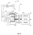
- FIG. 12is a schematic diagram illustrating an exemplary cooling feedback system 242 .
- Cooling feedback system 242includes a cooling device 244 .
- Cooling device 244may include multiple cooling garments.
- Cooling device 244 illustrated in FIG. 12includes three cooling garments: a headgear 228 and two body gear 230 .
- the cooling garments of cooling device 244function as described above.
- cooling device 244 of FIG. 12consists of three cooling garments, the number of cooling garments is not restricted to three.
- cooling device 244may include a single cooling garment or more than one cooling garment.
- Cooling device 244also need not be restricted to cooling the head, groin, and armpit areas of patient 12 .
- cooling device 244may include cooling garments that cover other areas of the body of patient 12 , such as a torso, an arm, a leg, or the like.
- a coolant supply container 232 and a carrier gas supply container 234may supply coolant and carrier gas and warm air to headgear 228 and body gear 230 via coolant supply 233 and carrier gas supply 235 .
- a warm air supply source 236may provide warm air to areas of the body of patient 12 via warm air supply 237 .
- a container supply box 238may house the coolant supply container 232 , carrier gas supply container 234 , warm air supply source 236 as described above.
- Each cooling garmentmay receive the coolant and carrier gas from the same respective supply containers. Alternatively, each cooling garment may receive coolant and carrier gas from separate respective supply containers. In a typical embodiment of the invention, the coolant and carrier gas received by each cooling garment may be individually controlled.
- a single warm air supply sourcemay provide warm air to several body sites, other sites may be served by individual warm air sources.
- the warm air supplied to each sitemay be individually controlled.
- Cooling device 244includes one or more sensors (not shown in FIG. 12 ) to measure a signal as a function of a patient parameter.
- the sensormay be in contact with the body within any of the cooling garments.
- headgear 228 and each of body gear 230may each include a sensor.
- the sensorsmay also be placed outside of the cooling garments. Sensors outside of the cooling garments may be in contact with the body of patient 12 .
- a tympanic temperature sensormay be placed in the ear of patient 12 , or temperature sensors may measure oral, rectal or bladder temperatures.
- sensors outside of the cooling garmentsmay be located within supplies, such as within coolant supply 233 , carrier gas supply 235 , or warm air supply 237 .
- Sensorsmay generate signals as a function of a patient parameter such as temperature, oxygen saturation levels, blood flow, heart rate, brain electrical action, end tidal carbon dioxide levels or the like.
- the sensormay generate a signal as a function of a cooling element parameter such as the temperature of the coolant, temperature of the gas, flow rate of the gas, flow rate of the coolant, and the like.
- Cooling device 244communicates the signals from the sensors of the cooling garments to a controller 246 via a communication bundle 245 , a wireless link, or any other communication devices.
- cooling feedback system 242may contain a communication bundle 245 that contains one or more communication links extending from cooling device 244 .
- Communication bundle 245may relay the signals from the sensors of the cooling garments to a controller 246 .
- Communication bundle 245may communicate the signals directly from the sensors to controller 246 .
- the signals from the sensorsmay be processed at cooling device 244 before being communicated to controller 246 .
- the communication links within the cooling garmentsmay communicate the signals generated by the sensors to one or more processors within cooling device 244 for processing.
- the processors in cooling device 244may, for example, compare the signals to thresholds, filter the signals and convert them from analog signals to digital signals with an analog to digital (A/D) converter.
- the processors in cooling device 244may also encode the signals for transmission to controller 246 . Encoding the signals may allow the use of smaller communication bundles 245 , which are less likely to interfere with the emergency medical personnel, doctors, or other users of cooling feedback system 242 .
- the processor of cooling device 244may be located within any of the cooling garments of cooling device 244 .
- a single processormay process the signals of all of the cooling garments of cooling device 244 .
- a separate processor housed in each separate cooling garmentmay process the signals from the sensors of the respective cooling garment.
- Controller 246receives signals from cooling device 244 via communication bundle 245 .
- Controller 246may include a processor that processes the signals.
- the processor in controller 246may perform comparing, filtering and A/D conversion.
- the processor in controller 246may further process the signal for display to a user, such as emergency medical personnel, a doctor, or any other user via a display.
- Controller 246may receive an ECG signal, for example, and display it to the user via a display.
- Controller 246may receive input from the user, such as a desired value of a patient parameter. For example, controller 246 may receive input from the user indicating a desired core body temperature or range of body temperatures. When controller 246 receives signals from temperature sensors, controller 246 may determine whether cooling device 244 is operating within the desired range by comparing the signals from the temperature sensors to the desired core body temperature input by the user. Controller 246 may compare the signal from each of the temperature sensors to the input core body temperature. Furthermore, the user may input a desired value for other variables such as a minimum heart rate, high and low oxygen saturation levels or the like. Cooling may have an effect upon one or more of these patient parameters, which the sensors may monitor.
- controller 246may adjust the delivery of one or more of the coolant, carrier gas, and/or warm air. With an adjustment to the coolant, carrier gas, and/or warm air, cooling device 244 may bring the patient parameter into the appropriate range. Further, controller 246 may sound an alarm to notify the user that cooling device 244 is operating outside an appropriate range.
- a usermay program controller 246 to recognize a minimum threshold core body temperature.
- temperature sensorsmay monitor core body temperature, and one or more processors may compare the measured body temperature to the minimum threshold core body temperature.
- controller 246may send a regulation signal to a regulator 248 via a feedback link 249 .
- Feedback link 249may be an optical fiber link, a wireless link, a wire link, or the like.
- Regulator 248may receive the regulation signal from controller 246 , and adjust the delivery of coolant, carrier gas, and/or warm air in response to the signal.
- Controller 246may, for example, send a regulation signal to regulator 248 directing the regulator to reduce the amount of carrier gas supplied to one or more cooling garments.
- regulator 248may adjust a valve or other regulation mechanism to reduce the flow rate of carrier gas to one or more cooling garments. Cooling garments may be individually regulated. Regulator 248 may adjust the carrier gas in ways other than or in addition to flow rate, such as by adjusting the temperature of the carrier gas, adjusting the mixing ratio of the carrier gas, or changing the speed of a fan. Furthermore, regulator 248 may adjust the delivery of coolant or warm air at the same time.
- a usermay program controller 246 to recognize different ranges of body temperatures, such as a high range of temperatures and a low range of temperatures.
- controller 246may send a regulation signal to a regulator 248 via a feedback link 249 to pursue an aggressive cooling therapy.
- cooling feedback system 242may include a “blast” cooling mode that provides rapid cooling to patients that may benefit from it.
- the blast cooling modemay cool the body below the frostbite level for a few minutes and then proceed to cool the body more conservatively.
- the blast coolingmay be discontinued before frostbite sets in.
- controller 246may send a regulation signal to a regulator 248 to pursue more moderate cooling therapy instead of maintaining an aggressive cooling therapy for that few minutes.
- Regulator 248may adjust the delivery of coolant, carrier gas, and/or warm air in response to the signals from controller 246 .
- feedback system 242may also control devices that supplement the cooling process of cooling device 244 .
- feedback system 242may regulate the amount of oxygen supplied to patient 12 , the temperature of the cool saline injected into patient 12 , or the amount of cool saline injected into patient 12 .
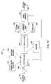
- FIG. 13is a block diagram illustrating cooling feedback system 242 .
- a usersuch as emergency medical personnel or a doctor, may input a desired value for a parameter of patient 12 .
- the usermay program a desired temperature 251 .
- temperature 251will be assumed to be a target body temperature.
- Feedback system 242may compare desired temperature 251 programmed by the user to a temperature signal generated by a temperature sensor 252 .
- Temperature sensor 252may measure a temperature such as the core body temperature or the skin temperature of the body.
- the output signal 258may be the actual temperature of patient 12 as measured by temperature sensor 252 .
- Controller 246receives an error signal 259 as a function of the difference between desired temperature 251 and output temperature 258 measured by temperature sensor 252 . Controller 246 may use error signal 259 to determine whether cooling device 244 has produced a body temperature that is at, above, or below the target body temperature. Controller 246 may transmit a regulation signal to regulator 248 based on the determination.
- Regulator 248may adjust one or more of coolant 232 , carrier gas 234 and/or warm air 236 in response to the regulation signal. Coolant 232 , carrier gas 234 and/or warm air 236 may affect the body temperature of patient 12 , which is measured by temperature sensor 252 . Regulator 248 may regulate coolant 232 , carrier gas 234 and warm air 236 independently by, for example, controlling coolant supply container 232 , the carrier gas supply container 234 , and warm air supply source 236 .
- Controller 246need not rely on error signal 259 , and may further receive a signal directly from temperature sensor 252 . Controller 246 may transmit a regulation signal to regulator 248 based on the actual temperature as measured by temperature sensor 252 .
- controller 246may receive signals from other sensors such as a heart rate sensor 254 , an oxygen sensor 255 , or a carbon dioxide sensor. Controller 246 may regulate cooling device 244 as a function of error signal 259 as long as the heart rate and oxygen saturation level are within a safe range. However, if the heart rate or oxygen saturation level of patient 12 were to enter an unsafe range, controller 246 may begin to regulate cooling device 244 in response to the signal received directly from sensor 254 or 255 , respectively. Controller 246 may, for example, scale back cooling until the heart range is back in a safe range. In other words, controller 246 may be programmed to judge a safe heart rate or oxygen saturation level as having a higher priority than a desired body temperature. The prioritization scheme may be programmed by the user. Controller 246 may further allow the user to manually turn the cooling system on and off.
- sensorssuch as a heart rate sensor 254 , an oxygen sensor 255 , or a carbon dioxide sensor. Controller 246 may regulate cooling device 244 as a function of error signal 259
- controller 246may sound an alarm 256 to alert the user.
- Alarm 256may have multiple sounds to indicate which variable of patient 12 is outside of the desired operating range.
- the alarmmay also comprise a computer-generated voice.
- controller 246may cause an indication message to appear on the user display concurrently with the sound emitted by alarm 256 .
- controller 246may receive a signal from heart rate sensor 254 that the heart is in ventricular fibrillation. Controller may sound an alarm 256 and may display a visual message as well. In these circumstances, restarting the heart may be more important than cooling. Controller 246 may alter or suspend cooling functions in one or more cooling garments until the patient has been returned to a normal sinus rhythm. Further, controller 246 may turn on the cooling when ventricular fibrillation is detected.
- FIG. 14is a flowchart illustrating the interaction of various feedback components to control the cooling of patient 12 .
- Controller 246may receive user input from a user ( 260 ).
- the user input received by controller 246may include a programmed target core body temperature, a minimum skin temperature, high and low temperature ranges, a minimum heart rate, high and low oxygen saturation levels, high and low end-tidal carbon dioxide levels or the like.
- Sensors within cooling device 244 or separate from the cooling garmentsgenerate signals as a function of a patient parameter ( 261 ). For instance, a sensor 54 within one of the cooling garments of cooling device 244 may generate a signal as a function of the temperature of patient 12 .
- a communication linkmay relay the signal to a processor within cooling device 244 for processing.
- the processormay receive signals from multiple sensors, and may process the signals in order to generate a signal that represents the information from the multiple sensors.
- Communication bundles 245may relay the raw or processed signals from cooling device 244 to controller 246 ( 262 ).
- Controller 246receives a signal via communication bundle 245 ( 264 ). For example, controller 246 may receive a signal indicating the core body temperature of patient 12 within headgear 228 and another signal indicating the core body temperature of patient 12 within body gear 230 . Controller 246 compares the received signals with the input values received from the user ( 266 ), and determines whether the cooling device 244 is operating within an appropriate range ( 268 ). For example, controller 246 may receive the core body temperature of patient 12 within headgear 228 , and compare the actual core body temperature of patient 12 with the target core body temperature input by the user.
- controller 246may determine whether another variable has a higher priority ( 270 ). Controller 246 may be receiving a plurality of signals as a function of a plurality of patient parameters, and a parameter such as an abnormal heart rate or rhythm may have a higher priority in determining the operation of cooling device 244 . When no other parameter has a higher priority, controller 246 may generate a regulation signal indicating to regulator 248 the adjustments necessary to bring cooling device 244 to the appropriate operating range or to maintain cooling device 244 in the appropriate operating range ( 272 ). Controller 246 may send the regulation signal to regulator 248 via feedback link 249 ( 274 ).
- Regulator 248receives the signal from controller 246 ( 276 ), and regulates the delivery of coolant, carrier gas, and/or warm air according to the regulation signal ( 278 ).
- regulator 248may close a carrier gas supply valve, increase the temperature of the coolant, decrease the flow rate of coolant, adjust the mixing ratio of the coolant, or otherwise adjust the operation of cooling device 244 .
- controller 246may include an algorithm for prevention of frostbite.
- the inventionmay provide numerous advantages.
- the feedback systemmay provide for a safe yet rapid lowering of the temperature of the patient, by continuously monitoring the condition of the patient. Should the patient be at risk of frostbite, for example, the system may automatically perform adjustments to reduce that risk.
- the systemmay respond to conditions other than temperature, and may regulate therapy as a function of those conditions. The system may further alert a health care professional of life-threatening conditions, such as a serious arrhythmia or cardiac arrest.
- the feedback systemmay regulate one or more cooling garments simultaneously.
- Each garmentmay be regulated individually for enhanced effect. Regulation of multiple garments allows the garments to work together in concert.
- the feedback systemis versatile and can be customized to the needs of each patient.
- a usermay program the system to supply appropriate therapy for the patient.
- the cooling garments and feedback systemmay further allow for hands free operation. For example, once on the body of the patient, the user may administer other treatments such as resuscitation.
- the cooling garmentsmay be constructed to be light and portable in some embodiments, and may be brought to the patient at the site of the traumatic event, or at least may be contained in an ambulance.
- the cooling feedback systemmay include different cooling algorithms for different traumatic events.
- the cooling feedback systemmay include separate cooling algorithms for traumatic events in which the patient has no blood flow, e.g., cardiac arrest, as opposed to traumatic events in which the patient maintains blood flow, e.g., brain injury and stroke.
- blood flowe.g., brain injury and stroke.
- an algorithm for traumatic events in which the patient has no blood flowmay include a more conservative cooling therapy.
Landscapes
- Engineering & Computer Science (AREA)
- Physics & Mathematics (AREA)
- General Physics & Mathematics (AREA)
- Automation & Control Theory (AREA)
- Health & Medical Sciences (AREA)
- Heart & Thoracic Surgery (AREA)
- Thermal Sciences (AREA)
- Biomedical Technology (AREA)
- Remote Sensing (AREA)
- Vascular Medicine (AREA)
- Life Sciences & Earth Sciences (AREA)
- Animal Behavior & Ethology (AREA)
- General Health & Medical Sciences (AREA)
- Public Health (AREA)
- Veterinary Medicine (AREA)
- Power Engineering (AREA)
- Thermotherapy And Cooling Therapy Devices (AREA)
Abstract
Description
Claims (40)
Priority Applications (3)
| Application Number | Priority Date | Filing Date | Title |
|---|---|---|---|
| US10/262,680US7087075B2 (en) | 2002-09-30 | 2002-09-30 | Feedback system for rapid induction of mild hypothermia |
| AU2003270917AAU2003270917A1 (en) | 2002-09-30 | 2003-09-30 | Feedback system for rapid induction of mild hypothermia |
| PCT/US2003/030695WO2004030587A1 (en) | 2002-09-30 | 2003-09-30 | Feedback system for rapid induction of mild hypothermia |
Applications Claiming Priority (1)
| Application Number | Priority Date | Filing Date | Title |
|---|---|---|---|
| US10/262,680US7087075B2 (en) | 2002-09-30 | 2002-09-30 | Feedback system for rapid induction of mild hypothermia |
Publications (2)
| Publication Number | Publication Date |
|---|---|
| US20040064171A1 US20040064171A1 (en) | 2004-04-01 |
| US7087075B2true US7087075B2 (en) | 2006-08-08 |
Family
ID=32030271
Family Applications (1)
| Application Number | Title | Priority Date | Filing Date |
|---|---|---|---|
| US10/262,680Expired - LifetimeUS7087075B2 (en) | 2002-09-30 | 2002-09-30 | Feedback system for rapid induction of mild hypothermia |
Country Status (3)
| Country | Link |
|---|---|
| US (1) | US7087075B2 (en) |
| AU (1) | AU2003270917A1 (en) |
| WO (1) | WO2004030587A1 (en) |
Cited By (30)
| Publication number | Priority date | Publication date | Assignee | Title |
|---|---|---|---|---|
| US20060111743A1 (en)* | 2004-11-19 | 2006-05-25 | Gurney Harry C Jr | Method for arresting seizure activity |
| US20060184047A1 (en)* | 1995-11-17 | 2006-08-17 | Yuichi Yamashita | Optical measurement instrument for living body |
| US20070106351A1 (en)* | 2005-11-08 | 2007-05-10 | Ferguson Ian G | System and method for changing and/or stabilizing the temperature of certain body parts |
| US20070198072A1 (en)* | 2004-01-22 | 2007-08-23 | Montain Scott J | Body thermoregulation using skin temperature feedback |
| US20090012402A1 (en)* | 2006-03-20 | 2009-01-08 | Mintz Frederick W | Mobile in vivo infra red data collection and diagnoses comparison system |
| US20090025483A1 (en)* | 2007-07-27 | 2009-01-29 | Robert Connor | Wearable position or motion sensing systems or methods |
| US20100211140A1 (en)* | 2005-05-13 | 2010-08-19 | Denise Barbut | Methods and devices for non-invasive cerebral and systemic cooling |
| US20110184252A1 (en)* | 2010-01-22 | 2011-07-28 | Ian Archer | Life support and microclimate integrated system and process |
| US20110224760A1 (en)* | 2010-03-12 | 2011-09-15 | Potter Charles F | Thermal Regulation Blanket and Method of Use Thereof |
| WO2012083151A1 (en) | 2010-12-16 | 2012-06-21 | Scion Neurostim, Llc | Systems, methods and apparatus for delivering nerve stimulation to a patient with physician oversight |
| US8236038B2 (en) | 2006-04-20 | 2012-08-07 | University Of Pittsburgh-Of The Commonwealth System Of Higher Education | Method and apparatus of noninvasive, regional brain thermal stimuli for the treatment of neurological disorders |
| US8425583B2 (en) | 2006-04-20 | 2013-04-23 | University of Pittsburgh—of the Commonwealth System of Higher Education | Methods, devices and systems for treating insomnia by inducing frontal cerebral hypothermia |
| US20130222139A1 (en)* | 2011-08-24 | 2013-08-29 | Safetyminded Holdings, Inc. | Human safety indicator |
| US20140135879A1 (en)* | 2008-10-08 | 2014-05-15 | Bedrock Inventions, Llc | Method and apparatus for measuring and treating shivering during therapeutic temperature control |
| US20150320592A1 (en)* | 2014-05-09 | 2015-11-12 | Scion Neurostim, Llc | Devices, Systems and Methods for Delivering Thermal Stimulation |
| US9211212B2 (en) | 2006-04-20 | 2015-12-15 | Cerêve, Inc. | Apparatus and method for modulating sleep |
| US9320644B2 (en) | 2011-07-25 | 2016-04-26 | Neurosave, Inc. | Non-invasive systems, devices, and methods for selective brain cooling |
| US9345614B2 (en) | 2014-07-25 | 2016-05-24 | Cascade Wellness Technologies, Inc. | Thermal contrast therapy devices, methods and systems |
| US9492313B2 (en) | 2006-04-20 | 2016-11-15 | University Of Pittsburgh - Of The Commonwealth System Of Higher Education | Method and apparatus of noninvasive, regional brain thermal stimuli for the treatment of neurological disorders |
| US9538949B2 (en) | 2010-09-28 | 2017-01-10 | Masimo Corporation | Depth of consciousness monitor including oximeter |
| US9588582B2 (en) | 2013-09-17 | 2017-03-07 | Medibotics Llc | Motion recognition clothing (TM) with two different sets of tubes spanning a body joint |
| EP3162329A1 (en) | 2010-06-29 | 2017-05-03 | Renato Rozental | Therapeutic brain cooling system and spinal cord cooling system |
| US20170192443A1 (en)* | 2013-04-16 | 2017-07-06 | Watlow Electric Manufacturing Company | Process controller with an integrated optical detector |
| US20170252206A1 (en)* | 2007-08-09 | 2017-09-07 | Zoll Circulation, Inc. | Devices and Methods for Using Endovascular Cooling to Treat Septic Shock and Other Disorders |
| US10058674B2 (en) | 2013-01-02 | 2018-08-28 | Ebb Therapeutics, Inc. | Systems for enhancing sleep |
| US10154815B2 (en) | 2014-10-07 | 2018-12-18 | Masimo Corporation | Modular physiological sensors |
| US10470922B1 (en) | 2018-05-14 | 2019-11-12 | Mark Louis Venturi | Blood flow restricting headwear |
| US10842406B2 (en) | 2017-02-08 | 2020-11-24 | Forest Devices, Inc. | Portable device for providing non-contact heat-evoked potentials |
| US11684510B2 (en) | 2006-04-20 | 2023-06-27 | University of Pittsburgh—of the Commonwealth System of Higher Education | Noninvasive, regional brain thermal stimuli for the treatment of neurological disorders |
| US12290640B2 (en) | 2006-04-20 | 2025-05-06 | University of Pittsburgh—of the Commonwealth System of Higher Education | Noninvasive, regional brain thermal stimulation for inducing relaxation |
Families Citing this family (63)
| Publication number | Priority date | Publication date | Assignee | Title |
|---|---|---|---|---|
| US6974463B2 (en)* | 1999-02-09 | 2005-12-13 | Innercool Therapies, Inc. | System and method for patient temperature control employing temperature projection algorithm |
| US6464716B1 (en) | 1998-01-23 | 2002-10-15 | Innercool Therapies, Inc. | Selective organ cooling apparatus and method |
| US7914564B2 (en)* | 1999-02-09 | 2011-03-29 | Innercool Therapies, Inc. | System and method for patient temperature control employing temperature projection algorithm |
| US7547320B2 (en) | 2002-07-11 | 2009-06-16 | Life Recovery System Hd, Llc | Apparatus for altering the body temperature of a patient |
| US7666213B2 (en)* | 2002-07-11 | 2010-02-23 | Life Recovery Systems Hd, Llc | Apparatus for altering the body temperature of a patient |
| US7300453B2 (en)* | 2003-02-24 | 2007-11-27 | Innercool Therapies, Inc. | System and method for inducing hypothermia with control and determination of catheter pressure |
| CA2559403C (en)* | 2004-01-22 | 2013-01-15 | Amir Belson | Respiratory system for inducing therapeutic hypothermia |
| US7896910B2 (en) | 2004-05-17 | 2011-03-01 | Coolsystems, Inc. | Modular apparatus for therapy of an animate body |
| AT413480B (en)* | 2004-06-23 | 2006-03-15 | Emcools Emergency Medical Cool | DEVICE FOR COOLING A PATIENT AND DEVICE FOR DELIVERING THE COLD TO A PATIENT |
| US7377935B2 (en) | 2004-09-24 | 2008-05-27 | Life Recovery Systems Hd, Llc | Apparatus for altering the body temperature of a patient |
| US20080269852A1 (en)* | 2005-04-07 | 2008-10-30 | Medcool, Inc | Methods and Apparatus for Thermal Regulation of a Body |
| US20070016256A1 (en)* | 2005-07-18 | 2007-01-18 | Korb Donald R | Method and apparatus for treating gland dysfunction |
| US8950405B2 (en) | 2006-05-15 | 2015-02-10 | Tearscience, Inc. | Treatment of obstructive disorders of the eye or eyelid |
| US20070060988A1 (en) | 2005-07-18 | 2007-03-15 | Grenon Stephen M | Melting meibomian gland obstructions |
| US20080114423A1 (en) | 2006-05-15 | 2008-05-15 | Grenon Stephen M | Apparatus for inner eyelid treatment of meibomian gland dysfunction |
| US7981095B2 (en) | 2005-07-18 | 2011-07-19 | Tearscience, Inc. | Methods for treating meibomian gland dysfunction employing fluid jet |
| US7981145B2 (en)* | 2005-07-18 | 2011-07-19 | Tearscience Inc. | Treatment of meibomian glands |
| US20090043365A1 (en) | 2005-07-18 | 2009-02-12 | Kolis Scientific, Inc. | Methods, apparatuses, and systems for reducing intraocular pressure as a means of preventing or treating open-angle glaucoma |
| US7981146B2 (en)* | 2006-05-15 | 2011-07-19 | Tearscience Inc. | Inner eyelid treatment for treating meibomian gland dysfunction |
| WO2013003594A2 (en) | 2011-06-28 | 2013-01-03 | Tearscience, Inc. | Methods and systems for treating meibomian gland dysfunction using radio-frequency energy |
| US20070095088A1 (en)* | 2005-10-20 | 2007-05-03 | Tiax Llc | Body ventilation system and method |
| WO2007056130A2 (en)* | 2005-11-07 | 2007-05-18 | Wasowski Peter Z | Grounded pressure cooling |
| US7981147B2 (en)* | 2006-05-15 | 2011-07-19 | Tearscience, Inc. | Outer eyelid heat and pressure treatment for treating meibomian gland dysfunction |
| US8137390B2 (en)* | 2006-05-15 | 2012-03-20 | Tearscience, Inc. | System for providing heat treatment and heat loss reduction for treating meibomian gland dysfunction |
| US8128673B2 (en) | 2006-05-15 | 2012-03-06 | Tearscience, Inc. | System for inner eyelid heat and pressure treatment for treating meibomian gland dysfunction |
| US9314369B2 (en) | 2006-05-15 | 2016-04-19 | Tearscience, Inc. | System for inner eyelid treatment of meibomian gland dysfunction |
| US8007524B2 (en)* | 2006-05-15 | 2011-08-30 | Tearscience, Inc. | Heat treatment and heat loss reduction for treating meibomian gland dysfunction |
| US8128674B2 (en) | 2006-05-15 | 2012-03-06 | Tearscience, Inc. | System for outer eyelid heat and pressure treatment for treating meibomian gland dysfunction |
| US7976573B2 (en)* | 2006-05-15 | 2011-07-12 | Tearscience, Inc. | Inner eyelid heat and pressure treatment for treating meibomian gland dysfunction |
| HUP0600516A2 (en)* | 2006-06-22 | 2008-04-28 | Janos Darabos | Therapeutical equipment for treating aortic stenosis |
| US7771461B2 (en) | 2006-08-24 | 2010-08-10 | Life Recovery Systems Hd, Llc | Apparatus for altering the body temperature of a patient |
| US20080221493A1 (en)* | 2006-12-07 | 2008-09-11 | Life Recovery Systems Hd, Llc | Apparatus for altering the body temperature of a patient and administering decompression to the patients torso |
| WO2008070849A2 (en) | 2006-12-07 | 2008-06-12 | Life Recovery Systems Hd, Llc | Apparatus for altering the body temperature of a patient |
| US7837638B2 (en) | 2007-02-13 | 2010-11-23 | Coolsystems, Inc. | Flexible joint wrap |
| USD638128S1 (en) | 2009-10-06 | 2011-05-17 | Tearscience, Inc. | Ocular device design |
| EP3714848A1 (en) | 2009-10-22 | 2020-09-30 | Coolsystems, Inc. | Temperature and flow control methods in a thermal therapy device |
| US9744071B2 (en)* | 2010-02-16 | 2017-08-29 | The Johns Hopkins University | Method and device for non-invasive anatomical and systemic cooling and neuroprotection |
| WO2011161571A1 (en)* | 2010-06-22 | 2011-12-29 | Koninklijke Philips Electronics N.V. | Device for monitoring an object, and method and system for monitoring and cooling an object |
| US9615967B2 (en) | 2010-12-30 | 2017-04-11 | Coolsystems, Inc. | Reinforced therapeutic wrap and method |
| US20130013033A1 (en)* | 2011-04-06 | 2013-01-10 | Coolsystems, Inc. | System for Providing Treatment to a Mammal and Method |
| US10463565B2 (en) | 2011-06-17 | 2019-11-05 | Coolsystems, Inc. | Adjustable patient therapy device |
| JP5934971B2 (en)* | 2011-07-01 | 2016-06-15 | 国立大学法人 筑波大学 | Wearable motion assist device |
| US20130090683A1 (en)* | 2011-10-05 | 2013-04-11 | Life Recovery Systems Hd, Llc | System for maintaining or altering the body temperature and method of use |
| EP2768458A1 (en)* | 2011-10-21 | 2014-08-27 | Dräger Medical GmbH | Warming therapy patient care units with automated weaning modes |
| CA2880888A1 (en)* | 2012-08-03 | 2014-02-06 | Board Of Regents, The University Of Texas System | Devices, systems and methods for thermoelectric heating and cooling of mammalian tissue |
| US10842670B2 (en) | 2012-08-22 | 2020-11-24 | Johnson & Johnson Vision Care, Inc. | Apparatuses and methods for diagnosing and/or treating lipid transport deficiency in ocular tear films, and related components and devices |
| EP3744391B1 (en) | 2013-04-30 | 2023-03-01 | Alcon Inc. | Systems for the treatment of eye conditions |
| US9763827B2 (en) | 2013-04-30 | 2017-09-19 | Tear Film Innovations, Inc. | Systems and methods for the treatment of eye conditions |
| US10238831B2 (en) | 2013-09-08 | 2019-03-26 | Qool Therapeutics, Inc. | Temperature measurement and feedback for therapeutic hypothermia |
| EP3046609B1 (en)* | 2013-09-18 | 2019-06-19 | Inhaletech LLC | Body core temperature cooling device |
| US10456320B2 (en) | 2013-10-01 | 2019-10-29 | Coolsystems, Inc. | Hand and foot wraps |
| US20160038336A1 (en) | 2014-08-05 | 2016-02-11 | Tamara L. HILTON | Integrated multisectional heat exchanger |
| WO2016138045A1 (en) | 2015-02-23 | 2016-09-01 | Qool Therapeutics, Inc. | Systems and methods for endotracheal delivery of frozen particles |
| US10667737B2 (en) | 2015-03-23 | 2020-06-02 | International Business Machines Corporation | Monitoring a person for indications of a brain injury |
| US20160331581A1 (en)* | 2015-05-12 | 2016-11-17 | International Business Machines Corporation | Helmet having an embedded cooling array |
| US20170105870A1 (en)* | 2015-10-14 | 2017-04-20 | Ataollah Yazdani | Fluid-based thermal clothing for heat exchange with body parts |
| US10859295B2 (en) | 2016-04-13 | 2020-12-08 | ZeoThermal Technologies, LLC | Cooling and heating platform |
| US10974063B2 (en) | 2016-06-30 | 2021-04-13 | Alcon Inc. | Light therapy for eyelash growth |
| US10512798B2 (en) | 2016-08-05 | 2019-12-24 | Illinois Tool Works Inc. | Method and apparatus for providing air flow |
| MX2022007965A (en)* | 2019-12-24 | 2022-07-11 | Cipher Skin | Intelligent head protective equipment. |
| GB2601180B (en) | 2020-11-23 | 2025-07-23 | Cryogenx Ltd | A wearable cooling apparatus for on-site treatment of heat illness |
| CN113041015B (en)* | 2021-03-01 | 2022-05-24 | 中南大学湘雅医院 | Clinical head cooling device for neurosurgery |
| US20220287876A1 (en)* | 2021-03-10 | 2022-09-15 | C. R. Bard, Inc. | Thermoelectric Heating/Cooling Pad |
Citations (237)
| Publication number | Priority date | Publication date | Assignee | Title |
|---|---|---|---|---|
| GB764993A (en) | 1953-12-23 | 1957-01-02 | Stark Virgil | Improvements in refrigerated clothing |
| US3504674A (en) | 1966-12-22 | 1970-04-07 | Emil S Swenson | Method and apparatus for performing hypothermia |
| US3587577A (en) | 1970-05-09 | 1971-06-28 | Oleg Alexandrovich Smirnov | Device for applying selective and general hypothermy to and reheating of human body through the common integuments thereof |
| US3648765A (en)* | 1970-11-24 | 1972-03-14 | Us Navy | Temperature control system for space suit |
| US3811777A (en) | 1973-02-06 | 1974-05-21 | Johnson Res Foundation Medical | Time-sharing fluorometer and reflectometer |
| US3830222A (en) | 1972-07-07 | 1974-08-20 | Johnson Res Foundation | Method and apparatus for observing rates of reaction of oxygen in living tissues |
| US3871381A (en) | 1971-12-30 | 1975-03-18 | Donald J Roslonski | Cold compress device |
| US3963351A (en) | 1975-04-14 | 1976-06-15 | Britton Chance | Multi-channel optical time-sharing apparatus having a rotating filter wheel with position-encoding means |
| US4023905A (en) | 1975-12-29 | 1977-05-17 | Britton Chance | Flash photolysis split beam spectrophotometer |
| US4118946A (en) | 1976-11-23 | 1978-10-10 | Eddie Sam Tubin | Personnel cooler |
| US4138743A (en) | 1975-02-25 | 1979-02-13 | Acurex Corporation | Liquid cooled helmet |
| US4162405A (en) | 1978-05-23 | 1979-07-24 | Britton Chance | Flying spot fluoro-meter for oxidized flavoprotein and reduced pyridine nucleotide |
| US4172495A (en) | 1977-08-03 | 1979-10-30 | Energy Systems Corporation | Slurry cooling of helmets |
| US4191028A (en)* | 1978-06-22 | 1980-03-04 | United States Of America As Represented By The Secretary Of The Navy | Dry ice, liquid pulse pump cooling system |
| DE2851602A1 (en) | 1978-11-29 | 1980-06-12 | Messerschmitt Boelkow Blohm | Medical cooling device for localised inflammation - with Peltier element between heat conductive block and cooling pad applied to patient's skin |
| US4292973A (en) | 1977-09-25 | 1981-10-06 | Kabushiki Kaisha Kurio-Medikaru | Apparatus for refrigeration treatment |
| US4353359A (en) | 1979-07-16 | 1982-10-12 | Milbauer Nathaniel A | Portable jacket for treatment and protection of injured body members |
| US4378797A (en) | 1980-04-14 | 1983-04-05 | Thomas Jefferson University | Extravascular circulation of oxygenated synthetic nutrients to treat tissue hypoxic and ischemic disorders |
| US4380240A (en) | 1977-06-28 | 1983-04-19 | Duke University, Inc. | Apparatus for monitoring metabolism in body organs |
| US4382446A (en) | 1980-10-23 | 1983-05-10 | Kay Laboratories, Inc. | Heat transfer devices for the scalp |
| US4416285A (en) | 1978-11-29 | 1983-11-22 | Oximetrix, Inc. | Improved optical catheter and method for making same |
| US4425916A (en) | 1979-06-01 | 1984-01-17 | Therapeutic Products, Inc. | Cap structure for creating temperature controlled environment for reducing alopecia |
| US4441502A (en) | 1982-08-19 | 1984-04-10 | Britton Chance | NMR System for determining relationship between work output and oxidative phosphorylation capability in an exercising body member |
| US4452250A (en) | 1982-04-29 | 1984-06-05 | Britton Chance | NMR System for the non-invasive study of phosphorus metabilism |
| US4552149A (en) | 1982-11-19 | 1985-11-12 | Kabushiki Kaisha Dunlop Home Products | Head cooling implement |
| US4570638A (en) | 1983-10-14 | 1986-02-18 | Somanetics Corporation | Method and apparatus for spectral transmissibility examination and analysis |
| US4638436A (en) | 1984-09-24 | 1987-01-20 | Labthermics Technologies, Inc. | Temperature control and analysis system for hyperthermia treatment |
| US4725147A (en) | 1984-09-17 | 1988-02-16 | Somanetics Corporation | Calibration method and apparatus for optical-response tissue-examination instrument |
| US4750493A (en) | 1986-02-28 | 1988-06-14 | Brader Eric W | Method of preventing brain damage during cardiac arrest, CPR or severe shock |
| US4753242A (en) | 1985-01-28 | 1988-06-28 | Saggers Michael J | Skull helmet for circulating cooling fluid |
| US4765338A (en) | 1982-12-29 | 1988-08-23 | Turner Richard W | Reuseable heat transfer devices for the scalp |
| US4768516A (en) | 1983-10-14 | 1988-09-06 | Somanetics Corporation | Method and apparatus for in vivo evaluation of tissue composition |
| US4817623A (en) | 1983-10-14 | 1989-04-04 | Somanetics Corporation | Method and apparatus for interpreting optical response data |
| US4817621A (en) | 1987-02-12 | 1989-04-04 | Eden Medizinische Elektronik Gmbh | Apparatus including doppler signal transducer for determing the position of an object |
| US4865038A (en) | 1986-10-09 | 1989-09-12 | Novametrix Medical Systems, Inc. | Sensor appliance for non-invasive monitoring |
| US4869250A (en) | 1985-03-07 | 1989-09-26 | Thermacor Technology, Inc. | Localized cooling apparatus |
| US4904237A (en) | 1988-05-16 | 1990-02-27 | Janese Woodrow W | Apparatus for the exchange of cerebrospinal fluid and a method of treating brain and spinal cord injuries |
| US4920963A (en) | 1986-02-28 | 1990-05-01 | Brader Eric W | Apparatus for preventing brain damage during cardiac arrest, CPR or severe shock |
| US4964408A (en) | 1988-04-29 | 1990-10-23 | Thor Technology Corporation | Oximeter sensor assembly with integral cable |
| US4972331A (en) | 1989-02-06 | 1990-11-20 | Nim, Inc. | Phase modulated spectrophotometry |
| US4981136A (en) | 1986-11-25 | 1991-01-01 | Performance Predictions, Inc. | Nuclear magnetic resonance apparatus for evaluating muscle efficiency and maximum power of muscle of a living animal |
| US4987896A (en) | 1981-03-28 | 1991-01-29 | Yoshiro Nakamatsu | Apparatus for increasing the activity of the human brain |
| US5062428A (en) | 1990-06-04 | 1991-11-05 | Nim Incorporated | Method and device for in vivo diagnosis detecting IR emission by body organ |
| US5080098A (en) | 1989-12-18 | 1992-01-14 | Sentinel Monitoring, Inc. | Non-invasive sensor |
| US5081991A (en) | 1989-03-14 | 1992-01-21 | Performance Predictions, Inc. | Methods and apparatus for using nuclear magnetic resonance to evaluate the muscle efficiency and maximum power of a subject during locomotion |
| US5090415A (en) | 1989-02-14 | 1992-02-25 | Hamamatsu Photonics Kabushiki Kaisha | Examination apparatus |
| US5094240A (en) | 1988-03-18 | 1992-03-10 | Nicolay Gmbh | Pulse/oxygen sensor and method of making |
| US5110721A (en) | 1989-02-10 | 1992-05-05 | The Research Foundation Of State University Of New York | Method for hypothermic organ protection during organ retrieval |
| US5119815A (en) | 1988-12-21 | 1992-06-09 | Nim, Incorporated | Apparatus for determining the concentration of a tissue pigment of known absorbance, in vivo, using the decay characteristics of scintered electromagnetic radiation |
| US5122974A (en) | 1989-02-06 | 1992-06-16 | Nim, Inc. | Phase modulated spectrophotometry |
| US5139025A (en) | 1983-10-14 | 1992-08-18 | Somanetics Corporation | Method and apparatus for in vivo optical spectroscopic examination |
| US5140989A (en) | 1983-10-14 | 1992-08-25 | Somanetics Corporation | Examination instrument for optical-response diagnostic apparatus |
| US5149321A (en) | 1990-10-10 | 1992-09-22 | Klatz Ronald M | Brain resuscitation device and method for performing the same |
| US5163425A (en) | 1985-05-27 | 1992-11-17 | Masao Nambu | Deformable cap for scalp cooling |
| US5167230A (en) | 1988-11-02 | 1992-12-01 | Nim, Inc. | User-wearable hemoglobinometer for measuring the metabolic condition of a subject |
| US5187672A (en) | 1989-02-06 | 1993-02-16 | Nim Incorporated | Phase modulation spectroscopic system |
| US5188108A (en) | 1990-02-15 | 1993-02-23 | Hewlett-Packard Company | Sensor, apparatus and method for non-invasive measurement of oxygen saturation |
| US5217013A (en) | 1983-10-14 | 1993-06-08 | Somanetics Corporation | Patient sensor for optical cerebral oximeter and the like |
| US5261243A (en) | 1992-09-28 | 1993-11-16 | Lockheed Corporation | Supplemental cooling system for avionic equipment |
| US5261399A (en) | 1991-05-22 | 1993-11-16 | Klatz Ronald M | Brain cooling device and method for performing the same |
| US5269758A (en) | 1992-04-29 | 1993-12-14 | Taheri Syde A | Intravascular catheter and method for treatment of hypothermia |
| US5285781A (en) | 1990-05-26 | 1994-02-15 | Stiwell S. A. | Electrical neuromuscular stimulation device |
| US5287705A (en) | 1993-02-16 | 1994-02-22 | Thermo King Corporation | Air conditioning and refrigeration systems utilizing a cryogen |
| US5350417A (en) | 1993-05-18 | 1994-09-27 | Augustine Medical, Inc. | Convective thermal blanket |
| US5353799A (en) | 1991-01-22 | 1994-10-11 | Non Invasive Technology, Inc. | Examination of subjects using photon migration with high directionality techniques |
| US5365607A (en) | 1993-08-26 | 1994-11-22 | Benevento Jr Vincenzo P | Cap having evaporative cooling interior apparatus |
| US5383918A (en) | 1992-08-31 | 1995-01-24 | Panetta; Thomas F. | Hypothermia reducing body exclosure |
| US5386827A (en) | 1993-03-30 | 1995-02-07 | Nim Incorporated | Quantitative and qualitative in vivo tissue examination using time resolved spectroscopy |
| US5395314A (en) | 1990-10-10 | 1995-03-07 | Life Resuscitation Technologies, Inc. | Brain resuscitation and organ preservation device and method for performing the same |
| US5402778A (en) | 1993-01-19 | 1995-04-04 | Nim Incorporated | Spectrophotometric examination of tissue of small dimension |
| US5408093A (en) | 1992-08-31 | 1995-04-18 | Hitachi, Ltd. | Optical computed tomography equipment having image inverting optical device |
| US5409005A (en) | 1993-10-07 | 1995-04-25 | Medasonics, Inc. | Transcranial doppler probe wheel and track/bar fixation assembly |
| US5449379A (en) | 1993-07-21 | 1995-09-12 | Alternative Compression Technologies, Inc. | Apparatus for applying a desired temperature and pressure to an injured area |
| US5465714A (en) | 1993-05-20 | 1995-11-14 | Somanetics Corporation | Electro-optical sensor for spectrophotometric medical devices |
| US5477853A (en) | 1992-12-01 | 1995-12-26 | Somanetics Corporation | Temperature compensation method and apparatus for spectroscopic devices |
| US5482034A (en) | 1993-05-28 | 1996-01-09 | Somanetics Corporation | Method and apparatus for spectrophotometric cerebral oximetry and the like |
| US5486204A (en) | 1994-09-20 | 1996-01-23 | University Of Texas Health Science Center Houston | Method of treating a non-penetrating head wound with hypothermia |
| US5531776A (en) | 1993-09-24 | 1996-07-02 | The Ohio State University | Non-invasive aortic impingement and core and cerebral temperature manipulation method |
| US5553614A (en) | 1988-12-21 | 1996-09-10 | Non-Invasive Technology, Inc. | Examination of biological tissue using frequency domain spectroscopy |
| US5555885A (en) | 1988-12-21 | 1996-09-17 | Non-Invasive Technology, Inc. | Examination of breast tissue using time-resolved spectroscopy |
| US5564417A (en) | 1991-01-24 | 1996-10-15 | Non-Invasive Technology, Inc. | Pathlength corrected oximeter and the like |
| US5571142A (en) | 1994-08-30 | 1996-11-05 | The Ohio State University Research Foundation | Non-invasive monitoring and treatment of subjects in cardiac arrest using ECG parameters predictive of outcome |
| US5584296A (en) | 1992-12-01 | 1996-12-17 | Somanetics Corporation | Patient sensor for optical cerebral oximeters and the like |
| US5584804A (en) | 1990-10-10 | 1996-12-17 | Life Resuscitation Technologies, Inc. | Brain resuscitation and organ preservation device and method for performing the same |
| US5596987A (en) | 1988-11-02 | 1997-01-28 | Noninvasive Technology, Inc. | Optical coupler for in vivo examination of biological tissue |
| US5603728A (en) | 1994-06-20 | 1997-02-18 | Pachys; Freddy | Scalp cooling/heating apparatus |
| US5658324A (en) | 1994-04-14 | 1997-08-19 | Promdx Technology Inc. | System and method for the reduction of secondary trauma |
| US5662690A (en) | 1994-12-08 | 1997-09-02 | Heartstream, Inc. | Defibrillator with training features and pause actuator |
| US5673701A (en) | 1994-10-07 | 1997-10-07 | Non Invasive Technology, Inc. | Optical techniques for examination of biological tissue |
| US5683438A (en) | 1995-03-10 | 1997-11-04 | Stanford University | Apparatus and method for core body warming of mammals experiencing hypothermia |
| US5697367A (en) | 1994-10-14 | 1997-12-16 | Somanetics Corporation | Specially grounded sensor for clinical spectrophotometric procedures |
| US5700828A (en) | 1995-12-07 | 1997-12-23 | Life Resuscitation Technologies, Inc. | Treatment or prevention of anoxic or ischemic brain injury with melatonin-containing compositions |
| US5713941A (en) | 1993-04-27 | 1998-02-03 | Cancer Research Institute | Apparatus for inducing whole body hyperthermia and method for treatment utilizing said whole body hyperthermia inducing apparatus |
| US5716386A (en) | 1994-06-27 | 1998-02-10 | The Ohio State University | Non-invasive aortic impingement and core and cerebral temperature manipulation |
| US5730730A (en) | 1995-09-29 | 1998-03-24 | Darling, Jr.; Phillip H. | Liquid flow rate control device |
| US5755756A (en) | 1995-09-15 | 1998-05-26 | Freedman, Jr.; Robert J. | Hypothermia-inducing resuscitation unit |
| US5779631A (en) | 1988-11-02 | 1998-07-14 | Non-Invasive Technology, Inc. | Spectrophotometer for measuring the metabolic condition of a subject |
| US5782755A (en) | 1993-11-15 | 1998-07-21 | Non-Invasive Technology, Inc. | Monitoring one or more solutes in a biological system using optical techniques |
| US5792051A (en) | 1988-12-21 | 1998-08-11 | Non-Invasive Technology, Inc. | Optical probe for non-invasive monitoring of neural activity |
| US5802865A (en) | 1997-09-05 | 1998-09-08 | The Sharper Image | Evaporative personal cooler |
| JPH10258080A (en) | 1997-03-21 | 1998-09-29 | Sanyo Mach Works Ltd | Electronic ice bag |
| US5820558A (en) | 1994-12-02 | 1998-10-13 | Non-Invasive Technology, Inc. | Optical techniques for examination of biological tissue |
| JPH10277080A (en) | 1997-04-02 | 1998-10-20 | Sakura Seiki Kk | Pillow for cooling |
| US5827222A (en) | 1990-10-10 | 1998-10-27 | Life Resuscitation Technologies, Inc. | Method of treating at least one of brain and associated nervous tissue injury |
| US5836993A (en) | 1996-05-16 | 1998-11-17 | Heartstream, Inc. | Electrotherapy device control system and method |
| US5837003A (en) | 1993-02-10 | 1998-11-17 | Radiant Medical, Inc. | Method and apparatus for controlling a patient's body temperature by in situ blood temperature modification |
| US5853370A (en) | 1996-09-13 | 1998-12-29 | Non-Invasive Technology, Inc. | Optical system and method for non-invasive imaging of biological tissue |
| US5860292A (en) | 1997-08-26 | 1999-01-19 | Augustine Medical, Inc. | Inflatable thermal blanket for convectively cooling a body |
| US5871526A (en) | 1993-10-13 | 1999-02-16 | Gibbs; Roselle | Portable temperature control system |
| WO1999008632A1 (en) | 1997-08-13 | 1999-02-25 | Life Science Holdings, Inc. | Brain cooling apparatus and method for cooling the brain |
| US5902235A (en) | 1989-03-29 | 1999-05-11 | Somanetics Corporation | Optical cerebral oximeter |
| WO1999023980A1 (en) | 1997-11-07 | 1999-05-20 | Hill-Rom, Inc. | Patient thermal regulation system |
| US5917190A (en) | 1993-10-29 | 1999-06-29 | Trustees Of The University Of Pennsylvania | Object imaging using diffuse light |
| US5916242A (en) | 1996-11-04 | 1999-06-29 | Schwartz; George R. | Apparatus for rapid cooling of the brain and method of performing same |
| WO1999044552A1 (en) | 1998-03-05 | 1999-09-10 | M.T.R.E. Advanced Technology Ltd. | System and method for heat control of a living body |
| US5954053A (en) | 1995-06-06 | 1999-09-21 | Non-Invasive Technology, Inc. | Detection of brain hematoma |
| US5957963A (en) | 1998-01-23 | 1999-09-28 | Del Mar Medical Technologies, Inc. | Selective organ hypothermia method and apparatus |
| US5964092A (en) | 1996-12-13 | 1999-10-12 | Nippon Sigmax, Co., Ltd. | Electronic cooling apparatus |
| US5987351A (en) | 1995-01-03 | 1999-11-16 | Non-Invasive Technology, Inc. | Optical coupler for in vivo examination of biological tissue |
| US6010528A (en) | 1996-08-30 | 2000-01-04 | Augustine Medical, Inc. | Support apparatus which cradles a body portion for application of localized cooling to high contact-pressure body surface areas |
| US6012179A (en)* | 1996-01-05 | 2000-01-11 | The Boc Group Plc | Garments for controlling body temperature |
| US6030412A (en) | 1991-05-22 | 2000-02-29 | Life Science Holdings, Inc. | Apparatus and method for cooling the brain, brain stem and associated neurologic tissues |
| US6044648A (en) | 1997-09-19 | 2000-04-04 | Forma Scientific, Inc. | Cooling device having liquid refrigerant injection ring |
| US6058324A (en) | 1993-06-17 | 2000-05-02 | Non-Invasive Technology, Inc. | Examination and imaging of biological tissue |
| WO2000033236A1 (en) | 1998-11-30 | 2000-06-08 | Health Hero Network, Inc. | System and method for improving a risk for a monitored client |
| US6090132A (en) | 1996-08-15 | 2000-07-18 | Fox; James Allan | Method and apparatus for inducing hypothermia |
| US6091989A (en) | 1998-04-08 | 2000-07-18 | Swerdlow; Charles D. | Method and apparatus for reduction of pain from electric shock therapies |
| US6101413A (en) | 1996-06-04 | 2000-08-08 | Survivalink Corporation | Circuit detectable pediatric defibrillation electrodes |
| US6110168A (en) | 1993-02-10 | 2000-08-29 | Radiant Medical, Inc. | Method and apparatus for controlling a patient's body temperature by in situ blood temperature modifications |
| US6126680A (en) | 1997-04-03 | 2000-10-03 | Mayo Foundation For Medical Education And Research | Selective convective brain cooling apparatus and method |
| US6141584A (en) | 1998-09-30 | 2000-10-31 | Agilent Technologies, Inc. | Defibrillator with wireless communications |
| US6148233A (en) | 1997-03-07 | 2000-11-14 | Cardiac Science, Inc. | Defibrillation system having segmented electrodes |
| US6149624A (en) | 1998-02-05 | 2000-11-21 | Mcshane; Richard Houston | Apparatus and method for the rapid induction of hypothermic brain preservation |
| US6149677A (en) | 1998-03-31 | 2000-11-21 | Innercool Therapies, Inc. | Circulating fluid hypothermia method |
| US6149670A (en) | 1999-03-11 | 2000-11-21 | Alsius Corporation | Method and system for treating cardiac arrest using hypothermia |
| US6156007A (en) | 1992-09-04 | 2000-12-05 | Hemotherm, Inc. | Apparatus for whole-body hyperthermia |
| US6156057A (en) | 1995-08-12 | 2000-12-05 | Fox; James Allan | Method for inducing hypothermia |
| US6183501B1 (en) | 1998-12-18 | 2001-02-06 | Jeffrey W. Latham | Head and spine cooling device |
| US6188930B1 (en) | 1998-09-11 | 2001-02-13 | Medivance Incorporated | Method and apparatus for providing localized heating of the preoptic anterior hypothalamus |
| US6209144B1 (en)* | 2000-01-10 | 2001-04-03 | Eddie R. Carter | Protective garment |
| US6248126B1 (en) | 1998-01-12 | 2001-06-19 | The Johns Hopkins University | Technique for using heat flow management to treat brain disorders |
| US6269267B1 (en) | 1998-09-02 | 2001-07-31 | Agilent Technologies, Inc. | Configurable arrhythmia analysis algorithm with security interface |
| US6277143B1 (en)* | 1991-05-22 | 2001-08-21 | Life Science Holdings, Inc. | Brain cooling apparatus and method for cooling the brain |
| US6283123B1 (en) | 1994-12-01 | 2001-09-04 | Keith W. Van Meter | Hyperbaric resuscitation system and method |
| US20010021866A1 (en) | 1998-01-23 | 2001-09-13 | Innercool Therapies Inc. | Method of making selective organ cooling catheter |
| US20010027334A1 (en) | 2000-02-08 | 2001-10-04 | White Anthony Dale | Body-cooling container |
| US20010027333A1 (en) | 1999-06-08 | 2001-10-04 | Schwartz Arthur E. | Intravascular systems for corporeal cooling |
| US6303156B1 (en) | 1998-06-24 | 2001-10-16 | The Brigham And Women's Hospital Inc. | Noninvasive method for increasing or decreasing the body temperature of a patient |
| US20010039439A1 (en) | 1998-10-16 | 2001-11-08 | William Elkins | Compliant heat exchange splint and control unit |
| US6321113B1 (en) | 1998-03-31 | 2001-11-20 | Survivalink Corporation | Automatic external defibrillator first responder and clinical data outcome management system |
| US6325818B1 (en) | 1999-10-07 | 2001-12-04 | Innercool Therapies, Inc. | Inflatable cooling apparatus for selective organ hypothermia |
| US20010049545A1 (en) | 1999-02-19 | 2001-12-06 | Lasersohn Jack W. | Method for treating cardiac arrest |
| US20010051801A1 (en) | 1997-02-27 | 2001-12-13 | Lehmann John W. | Cryosurgical catheter |
| WO2001095977A1 (en) | 2000-06-12 | 2001-12-20 | Cardiac Science, Inc. | A public access defibrillator |
| US20020002394A1 (en) | 1998-03-24 | 2002-01-03 | Dobak, John D. | Isolated selective organ cooling apparatus |
| US20020004729A1 (en) | 2000-04-26 | 2002-01-10 | Christopher Zak | Electronic data gathering for emergency medical services |
| US20020007201A1 (en) | 2000-04-20 | 2002-01-17 | Dennis Grahn | Methods and devices for extracting thermal energy from the body core of a mammal |
| US20020026226A1 (en) | 2000-01-27 | 2002-02-28 | Ein Robert J. | Therapeutic apparatus |
| US6354099B1 (en) | 2000-04-11 | 2002-03-12 | Augustine Medical, Inc. | Cooling devices with high-efficiency cooling features |
| US6356785B1 (en) | 1997-11-06 | 2002-03-12 | Cecily Anne Snyder | External defibrillator with CPR prompts and ACLS prompts and methods of use |
| US20020032473A1 (en) | 1999-09-09 | 2002-03-14 | M.T.R.E. Advanced Technologies Ltd. | Method and system for improving cardiovascular parameters of a patient |
| US6370428B1 (en) | 1999-08-11 | 2002-04-09 | David E. Snyder | Method for configuring a defibrillator |
| US6375673B1 (en) | 1998-04-23 | 2002-04-23 | The Board Of Regents Of The University Of Texas System | Heat transfer blanket for and method of controlling a patient's temperature |
| US6375674B1 (en) | 1999-01-04 | 2002-04-23 | Medivance, Inc. | Cooling/heating pad and system |
| US6389828B1 (en) | 2000-03-15 | 2002-05-21 | Michael R. Thomas | Cryogenic cooling chamber apparatus and method |
| WO2002041231A2 (en) | 2000-11-17 | 2002-05-23 | The Johns Hopkins University | Clinician's assistant system |
| US6402775B1 (en) | 1999-12-14 | 2002-06-11 | Augustine Medical, Inc. | High-efficiency cooling pads, mattresses, and sleeves |
| US20020072785A1 (en) | 1999-12-14 | 2002-06-13 | Medtronic, Inc. | Apparatus and method for remote therapy and diagnosis in medical devices via interface systems |
| US6406427B1 (en) | 1997-06-10 | 2002-06-18 | Auckland Uniservices Limited | Brain rescue instrument and method |
| US6409745B1 (en) | 2000-12-14 | 2002-06-25 | Her Majesty The Queen In Right Of Canada, As Represented By The Minister Of National Defence Of Her Majesty's Canadian Government | Field-deployable forced air warming system |
| US6416480B1 (en) | 1999-03-29 | 2002-07-09 | Valeriy Nenov | Method and apparatus for automated acquisition of the glasgow coma score (AGCS) |
| US20020091431A1 (en) | 1997-06-09 | 2002-07-11 | Auckland Uniservices Limited | System method for reducing brain injury particularly in newborn infants |
| US20020091428A1 (en) | 2000-10-05 | 2002-07-11 | Larnard Donald J. | Expandable device for thermal therapy |
| US20020095201A1 (en) | 1998-04-21 | 2002-07-18 | Worthen William J. | Method and system for treating cardiac arrest using hypothermia |
| US20020095200A1 (en) | 1998-01-23 | 2002-07-18 | Innercool Therapies, Inc. | Inflatable catheter for selective organ heating and cooling and method of using the same |
| US20020099427A1 (en) | 1998-06-23 | 2002-07-25 | Dobak John D. | Isolated selective organ cooling methd and apparatus |
| US6426759B1 (en) | 1995-10-20 | 2002-07-30 | Confer Software, Inc. | Apparatus and method for managing changes of computerized medical protocols |
| US20020103520A1 (en) | 1998-12-18 | 2002-08-01 | Latham Jeffrey Wade | Therapeutic cooling devices |
| US20020103508A1 (en) | 2001-01-29 | 2002-08-01 | Prabodh Mathur | Remotely operated defibrillator |
| US6432124B1 (en) | 1999-03-11 | 2002-08-13 | Alsius Corporation | Method and system treating heart malady such as cardiac arrest and heart attack using hypothermia |
| US20020116041A1 (en) | 2000-11-07 | 2002-08-22 | Daoud Adib Gabrail | Circulation set for temperature-controlled catheter and method of using the same |
| US20020120317A1 (en) | 2001-02-27 | 2002-08-29 | Fletcher Robert David | Apparatus for and method of cooling a brain |
| US6451045B1 (en) | 2001-02-22 | 2002-09-17 | Alsius Corporation | Heat exchange catheter having a helically wrapped heat exchanger |
| US20020138302A1 (en) | 2001-03-21 | 2002-09-26 | David Bodnick | Prepaid telecommunication card for health care compliance |
| US6461379B1 (en)* | 2001-04-30 | 2002-10-08 | Medivance, Incorporated | Localized bodily cooling/heating apparatus and method |
| US20020151946A1 (en) | 1998-01-23 | 2002-10-17 | Innercool Therapies, Inc. | Patient temperature regulation method and apparatus |
| US6473920B2 (en)* | 1999-11-12 | 2002-11-05 | Augustine Medical, Inc. | System for warming lower extremities of supine persons |
| US20020183815A1 (en) | 1998-01-23 | 2002-12-05 | Nest Mark Van | Method of manufacturing a heat transfer element for in vivo cooling |
| US20020183816A1 (en) | 2001-06-05 | 2002-12-05 | Alsius | Heat exchange catheter |
| US20020193852A1 (en) | 2001-02-28 | 2002-12-19 | Renfro William Leonard | Portable thermal rescue/recovery system |
| US20020193855A1 (en) | 1998-01-23 | 2002-12-19 | Innercool Therapies, Inc. | Patient temperature regulation method and apparatus |
| US20020193854A1 (en) | 1998-01-23 | 2002-12-19 | Innercool Therapies, Inc. | Selective organ cooling catheter with guidewire apparatus and temperature-monitoring device |
| US6497720B1 (en) | 1996-08-30 | 2002-12-24 | Augustine Medical, Inc. | Support apparatus with a plurality of thermal zones providing localized cooling |
| US6497358B1 (en) | 1999-09-13 | 2002-12-24 | Christopher S. Walsh | Record and verification method and system for radiation therapy |
| US6497721B2 (en) | 1993-02-10 | 2002-12-24 | Radiant Medical, Inc. | Method and apparatus for regional and whole body temperature modification |
| US20030018375A1 (en) | 1998-01-23 | 2003-01-23 | Dobak John D. | Selective organ cooling apparatus and method |
| US20030023288A1 (en) | 1999-02-09 | 2003-01-30 | Michael Magers | Method and device for patient temperature control employing optimized rewarming |
| US6520933B1 (en) | 1998-04-21 | 2003-02-18 | Alsius Corporation | Central venous line cooling catheter having a spiral-shaped heat exchange member |
| US20030036786A1 (en) | 2000-04-10 | 2003-02-20 | Duren Albert Philip Van | System, combination and method for controlling airflow in convective treatment |
| US6523354B1 (en) | 2002-03-08 | 2003-02-25 | Deborah Ann Tolbert | Cooling blanket |
| US20030040783A1 (en) | 1999-09-21 | 2003-02-27 | Salmon Andrew Paul Maxwell | Warming apparatus |
| US20030055473A1 (en) | 2001-09-17 | 2003-03-20 | Ramsden Vivian R. | Brain cooling device and monitoring system |
| US20030055472A1 (en) | 2001-09-19 | 2003-03-20 | Worthen William J. | Method for supporting medical practitioners in managing patient temperature |
| US20030060863A1 (en) | 1999-02-09 | 2003-03-27 | Dobak John D. | Method and apparatus for patient temperature control employing administration of anti-shivering agents |
| US20030060864A1 (en) | 2001-09-25 | 2003-03-27 | Mark Whitebook | Heating/cooling system for indwelling heat exchange catheter |
| US6544282B1 (en) | 2001-02-21 | 2003-04-08 | Radiant Medical, Inc. | Inhibition of platelet activation, aggregation and/or adhesion by hypothermia |
| US20030066304A1 (en) | 1999-08-02 | 2003-04-10 | Becker Lance B. | Method for inducing hypothermia |
| US6547811B1 (en) | 1999-08-02 | 2003-04-15 | Arch Development Corporation | Method for inducing hypothermia |
| US6551347B1 (en) | 1988-09-28 | 2003-04-22 | Life Enhancement Technologies, Inc. | Cooling/heating system |
| US6551348B1 (en) | 2001-01-26 | 2003-04-22 | Deroyal Industries, Inc. | Temperature controlled fluid therapy system |
| US6551349B2 (en) | 1998-03-24 | 2003-04-22 | Innercool Therapies, Inc. | Selective organ cooling apparatus |
| US20030078638A1 (en) | 2001-10-11 | 2003-04-24 | Marc Voorhees | Patient temperature control system with fluid temperature response |
| US20030083721A1 (en) | 2001-10-31 | 2003-05-01 | Seacoast Technologies, Inc. | Method and apparatus for thermal therapy |
| US20030083000A1 (en) | 2001-10-09 | 2003-05-01 | Errol Sambuco | Method of applying a surface finish on a metal substrate and method of preparing work rolls for applying the surface finish |
| US6558413B2 (en) | 1987-10-05 | 2003-05-06 | Augustine Medical, Inc. | Inflatable device with exhausting apertures which vary in density |
| US6558412B2 (en) | 1998-01-23 | 2003-05-06 | Innercool Therapies, Inc. | Selective organ hypothermia method and apparatus |
| US20030088299A1 (en) | 1999-02-09 | 2003-05-08 | Michael Magers | System and method for patient temperature control employing temperature projection algorithm |
| US6576002B2 (en) | 1998-03-24 | 2003-06-10 | Innercool Therapies, Inc. | Isolated selective organ cooling method and apparatus |
| US20030114903A1 (en) | 2001-10-11 | 2003-06-19 | Bruce Ellingboe | Patient temperature control system with fluid temperature response |
| US6582398B1 (en) | 1999-02-19 | 2003-06-24 | Alsius Corporation | Method of managing patient temperature with a heat exchange catheter |
| US6582455B1 (en) | 1998-03-24 | 2003-06-24 | Innercool Therapies, Inc. | Method and device for applications of selective organ cooling |
| US20030135252A1 (en) | 1998-08-24 | 2003-07-17 | Machold Timothy R. | Method and system for control of a patient's body temperature by way of transluminally insertable heat exchange catheter |
| US20030150545A1 (en) | 2000-10-19 | 2003-08-14 | Szczesuil Stephen P. | Method and apparatus for making body heating and cooling garments |
| US6607517B1 (en) | 2001-08-24 | 2003-08-19 | Radiant Medical, Inc. | Method of inotropic treatment of heart disease using hypothermia |
| US6610083B2 (en) | 1998-08-24 | 2003-08-26 | Radiant Medical, Inc. | Multiple lumen heat exchange catheters |
| US6623516B2 (en) | 1992-08-13 | 2003-09-23 | Mark A. Saab | Method for changing the temperature of a selected body region |
| US6645234B2 (en) | 1998-04-21 | 2003-11-11 | Alsius Corporation | Cardiovascular guiding catheter with heat exchange properties and methods of use |
| US20030216799A1 (en) | 2002-05-20 | 2003-11-20 | Alsius Corp. | Method and system for treating ischemia using hypothermia |
| US20030225336A1 (en) | 2002-03-21 | 2003-12-04 | Radiant Medical, Inc. | Devices and methods for measuring blood flow rate or cardiac output and for heating or cooling the body |
| US6682550B2 (en) | 1998-04-23 | 2004-01-27 | The Board Of Regents Of The University Of Texas | Heat transfer blanket for and method of controlling a patient's temperature |
| US6692518B2 (en)* | 2002-02-27 | 2004-02-17 | Medivance Incorporated | Patient temperature control system |
| US6697671B1 (en) | 1998-11-20 | 2004-02-24 | Medtronic Physio-Control Manufacturing C{overscore (o)}rp. | Visual and aural user interface for an automated external defibrillator |
| US20040158303A1 (en) | 2002-04-29 | 2004-08-12 | Medcool, Inc. | Method and device for rapidly inducing and then maintaining hypothermia |
| US6800087B2 (en) | 2000-01-07 | 2004-10-05 | The Cleveland Clinic Foundation | Blanket system for temperature regulation of a patient |
| US6813517B2 (en) | 2001-11-06 | 2004-11-02 | Medtronic Physio-Control Corp. | Configuring defibrillator energy dosing |
| US6829501B2 (en) | 2001-12-20 | 2004-12-07 | Ge Medical Systems Information Technologies, Inc. | Patient monitor and method with non-invasive cardiac output monitoring |
| US6887199B2 (en) | 1999-09-23 | 2005-05-03 | Active Signal Technologies, Inc. | Brain assessment monitor |
Family Cites Families (2)
| Publication number | Priority date | Publication date | Assignee | Title |
|---|---|---|---|---|
| US39439A (en)* | 1863-08-04 | Improvement | ||
| US5755631A (en)* | 1995-10-12 | 1998-05-26 | Paschka; Gary M. | Volleyball practice device and method of use thereof |
- 2002
- 2002-09-30USUS10/262,680patent/US7087075B2/ennot_activeExpired - Lifetime
- 2003
- 2003-09-30AUAU2003270917Apatent/AU2003270917A1/ennot_activeAbandoned
- 2003-09-30WOPCT/US2003/030695patent/WO2004030587A1/ennot_activeApplication Discontinuation
Patent Citations (272)
| Publication number | Priority date | Publication date | Assignee | Title |
|---|---|---|---|---|
| GB764993A (en) | 1953-12-23 | 1957-01-02 | Stark Virgil | Improvements in refrigerated clothing |
| US3504674A (en) | 1966-12-22 | 1970-04-07 | Emil S Swenson | Method and apparatus for performing hypothermia |
| US3587577A (en) | 1970-05-09 | 1971-06-28 | Oleg Alexandrovich Smirnov | Device for applying selective and general hypothermy to and reheating of human body through the common integuments thereof |
| US3648765A (en)* | 1970-11-24 | 1972-03-14 | Us Navy | Temperature control system for space suit |
| US3871381A (en) | 1971-12-30 | 1975-03-18 | Donald J Roslonski | Cold compress device |
| US3830222A (en) | 1972-07-07 | 1974-08-20 | Johnson Res Foundation | Method and apparatus for observing rates of reaction of oxygen in living tissues |
| US3811777A (en) | 1973-02-06 | 1974-05-21 | Johnson Res Foundation Medical | Time-sharing fluorometer and reflectometer |
| US4138743A (en) | 1975-02-25 | 1979-02-13 | Acurex Corporation | Liquid cooled helmet |
| US3963351A (en) | 1975-04-14 | 1976-06-15 | Britton Chance | Multi-channel optical time-sharing apparatus having a rotating filter wheel with position-encoding means |
| US4023905A (en) | 1975-12-29 | 1977-05-17 | Britton Chance | Flash photolysis split beam spectrophotometer |
| US4118946A (en) | 1976-11-23 | 1978-10-10 | Eddie Sam Tubin | Personnel cooler |
| US4380240A (en) | 1977-06-28 | 1983-04-19 | Duke University, Inc. | Apparatus for monitoring metabolism in body organs |
| US4510938A (en) | 1977-06-28 | 1985-04-16 | Duke University, Inc. | Body-mounted light source-detector apparatus |
| US4172495A (en) | 1977-08-03 | 1979-10-30 | Energy Systems Corporation | Slurry cooling of helmets |
| US4292973A (en) | 1977-09-25 | 1981-10-06 | Kabushiki Kaisha Kurio-Medikaru | Apparatus for refrigeration treatment |
| US4162405A (en) | 1978-05-23 | 1979-07-24 | Britton Chance | Flying spot fluoro-meter for oxidized flavoprotein and reduced pyridine nucleotide |
| US4191028A (en)* | 1978-06-22 | 1980-03-04 | United States Of America As Represented By The Secretary Of The Navy | Dry ice, liquid pulse pump cooling system |
| US4416285A (en) | 1978-11-29 | 1983-11-22 | Oximetrix, Inc. | Improved optical catheter and method for making same |
| DE2851602A1 (en) | 1978-11-29 | 1980-06-12 | Messerschmitt Boelkow Blohm | Medical cooling device for localised inflammation - with Peltier element between heat conductive block and cooling pad applied to patient's skin |
| US4425916A (en) | 1979-06-01 | 1984-01-17 | Therapeutic Products, Inc. | Cap structure for creating temperature controlled environment for reducing alopecia |
| US4353359A (en) | 1979-07-16 | 1982-10-12 | Milbauer Nathaniel A | Portable jacket for treatment and protection of injured body members |
| US4378797A (en) | 1980-04-14 | 1983-04-05 | Thomas Jefferson University | Extravascular circulation of oxygenated synthetic nutrients to treat tissue hypoxic and ischemic disorders |
| US4382446A (en) | 1980-10-23 | 1983-05-10 | Kay Laboratories, Inc. | Heat transfer devices for the scalp |
| US4987896A (en) | 1981-03-28 | 1991-01-29 | Yoshiro Nakamatsu | Apparatus for increasing the activity of the human brain |
| US4452250A (en) | 1982-04-29 | 1984-06-05 | Britton Chance | NMR System for the non-invasive study of phosphorus metabilism |
| US4441502A (en) | 1982-08-19 | 1984-04-10 | Britton Chance | NMR System for determining relationship between work output and oxidative phosphorylation capability in an exercising body member |
| US4552149A (en) | 1982-11-19 | 1985-11-12 | Kabushiki Kaisha Dunlop Home Products | Head cooling implement |
| US4765338A (en) | 1982-12-29 | 1988-08-23 | Turner Richard W | Reuseable heat transfer devices for the scalp |
| US4570638A (en) | 1983-10-14 | 1986-02-18 | Somanetics Corporation | Method and apparatus for spectral transmissibility examination and analysis |
| US5139025A (en) | 1983-10-14 | 1992-08-18 | Somanetics Corporation | Method and apparatus for in vivo optical spectroscopic examination |
| US4768516A (en) | 1983-10-14 | 1988-09-06 | Somanetics Corporation | Method and apparatus for in vivo evaluation of tissue composition |
| US4817623A (en) | 1983-10-14 | 1989-04-04 | Somanetics Corporation | Method and apparatus for interpreting optical response data |
| US5217013A (en) | 1983-10-14 | 1993-06-08 | Somanetics Corporation | Patient sensor for optical cerebral oximeter and the like |
| US5349961A (en) | 1983-10-14 | 1994-09-27 | Somanetics Corporation | Method and apparatus for in vivo optical spectroscopic examination |
| US5140989A (en) | 1983-10-14 | 1992-08-25 | Somanetics Corporation | Examination instrument for optical-response diagnostic apparatus |
| US4725147A (en) | 1984-09-17 | 1988-02-16 | Somanetics Corporation | Calibration method and apparatus for optical-response tissue-examination instrument |
| US4638436A (en) | 1984-09-24 | 1987-01-20 | Labthermics Technologies, Inc. | Temperature control and analysis system for hyperthermia treatment |
| US4753242A (en) | 1985-01-28 | 1988-06-28 | Saggers Michael J | Skull helmet for circulating cooling fluid |
| US4869250A (en) | 1985-03-07 | 1989-09-26 | Thermacor Technology, Inc. | Localized cooling apparatus |
| US5163425A (en) | 1985-05-27 | 1992-11-17 | Masao Nambu | Deformable cap for scalp cooling |
| US4920963A (en) | 1986-02-28 | 1990-05-01 | Brader Eric W | Apparatus for preventing brain damage during cardiac arrest, CPR or severe shock |
| US4750493A (en) | 1986-02-28 | 1988-06-14 | Brader Eric W | Method of preventing brain damage during cardiac arrest, CPR or severe shock |
| US4865038A (en) | 1986-10-09 | 1989-09-12 | Novametrix Medical Systems, Inc. | Sensor appliance for non-invasive monitoring |
| US4981136A (en) | 1986-11-25 | 1991-01-01 | Performance Predictions, Inc. | Nuclear magnetic resonance apparatus for evaluating muscle efficiency and maximum power of muscle of a living animal |
| US4817621A (en) | 1987-02-12 | 1989-04-04 | Eden Medizinische Elektronik Gmbh | Apparatus including doppler signal transducer for determing the position of an object |
| US6558413B2 (en) | 1987-10-05 | 2003-05-06 | Augustine Medical, Inc. | Inflatable device with exhausting apertures which vary in density |
| US5094240A (en) | 1988-03-18 | 1992-03-10 | Nicolay Gmbh | Pulse/oxygen sensor and method of making |
| US4964408A (en) | 1988-04-29 | 1990-10-23 | Thor Technology Corporation | Oximeter sensor assembly with integral cable |
| US4904237A (en) | 1988-05-16 | 1990-02-27 | Janese Woodrow W | Apparatus for the exchange of cerebrospinal fluid and a method of treating brain and spinal cord injuries |
| US6551347B1 (en) | 1988-09-28 | 2003-04-22 | Life Enhancement Technologies, Inc. | Cooling/heating system |
| US5596987A (en) | 1988-11-02 | 1997-01-28 | Noninvasive Technology, Inc. | Optical coupler for in vivo examination of biological tissue |
| US5779631A (en) | 1988-11-02 | 1998-07-14 | Non-Invasive Technology, Inc. | Spectrophotometer for measuring the metabolic condition of a subject |
| US5167230A (en) | 1988-11-02 | 1992-12-01 | Nim, Inc. | User-wearable hemoglobinometer for measuring the metabolic condition of a subject |
| US5119815A (en) | 1988-12-21 | 1992-06-09 | Nim, Incorporated | Apparatus for determining the concentration of a tissue pigment of known absorbance, in vivo, using the decay characteristics of scintered electromagnetic radiation |
| US5553614A (en) | 1988-12-21 | 1996-09-10 | Non-Invasive Technology, Inc. | Examination of biological tissue using frequency domain spectroscopy |
| US5792051A (en) | 1988-12-21 | 1998-08-11 | Non-Invasive Technology, Inc. | Optical probe for non-invasive monitoring of neural activity |
| US5555885A (en) | 1988-12-21 | 1996-09-17 | Non-Invasive Technology, Inc. | Examination of breast tissue using time-resolved spectroscopy |
| US5899865A (en) | 1988-12-21 | 1999-05-04 | Non-Invasive Technology, Inc. | Localization of abnormal breast tissue using time-resolved spectroscopy |
| US5122974A (en) | 1989-02-06 | 1992-06-16 | Nim, Inc. | Phase modulated spectrophotometry |
| US5187672A (en) | 1989-02-06 | 1993-02-16 | Nim Incorporated | Phase modulation spectroscopic system |
| US4972331A (en) | 1989-02-06 | 1990-11-20 | Nim, Inc. | Phase modulated spectrophotometry |
| US5110721A (en) | 1989-02-10 | 1992-05-05 | The Research Foundation Of State University Of New York | Method for hypothermic organ protection during organ retrieval |
| US5090415A (en) | 1989-02-14 | 1992-02-25 | Hamamatsu Photonics Kabushiki Kaisha | Examination apparatus |
| US5081991A (en) | 1989-03-14 | 1992-01-21 | Performance Predictions, Inc. | Methods and apparatus for using nuclear magnetic resonance to evaluate the muscle efficiency and maximum power of a subject during locomotion |
| US5902235A (en) | 1989-03-29 | 1999-05-11 | Somanetics Corporation | Optical cerebral oximeter |
| US5080098A (en) | 1989-12-18 | 1992-01-14 | Sentinel Monitoring, Inc. | Non-invasive sensor |
| US5188108A (en) | 1990-02-15 | 1993-02-23 | Hewlett-Packard Company | Sensor, apparatus and method for non-invasive measurement of oxygen saturation |
| US5285781A (en) | 1990-05-26 | 1994-02-15 | Stiwell S. A. | Electrical neuromuscular stimulation device |
| US5062428A (en) | 1990-06-04 | 1991-11-05 | Nim Incorporated | Method and device for in vivo diagnosis detecting IR emission by body organ |
| US5149321A (en) | 1990-10-10 | 1992-09-22 | Klatz Ronald M | Brain resuscitation device and method for performing the same |
| US5827222A (en) | 1990-10-10 | 1998-10-27 | Life Resuscitation Technologies, Inc. | Method of treating at least one of brain and associated nervous tissue injury |
| US5234405A (en) | 1990-10-10 | 1993-08-10 | Klatz Ronald M | Brain resuscitation device and method for performing the same |
| US5395314A (en) | 1990-10-10 | 1995-03-07 | Life Resuscitation Technologies, Inc. | Brain resuscitation and organ preservation device and method for performing the same |
| US5584804A (en) | 1990-10-10 | 1996-12-17 | Life Resuscitation Technologies, Inc. | Brain resuscitation and organ preservation device and method for performing the same |
| US5353799A (en) | 1991-01-22 | 1994-10-11 | Non Invasive Technology, Inc. | Examination of subjects using photon migration with high directionality techniques |
| US5664574A (en) | 1991-01-22 | 1997-09-09 | Non-Invasive Technology, Inc. | System for tissue examination using directional optical radiation |
| US5564417A (en) | 1991-01-24 | 1996-10-15 | Non-Invasive Technology, Inc. | Pathlength corrected oximeter and the like |
| US6277143B1 (en)* | 1991-05-22 | 2001-08-21 | Life Science Holdings, Inc. | Brain cooling apparatus and method for cooling the brain |
| US5261399A (en) | 1991-05-22 | 1993-11-16 | Klatz Ronald M | Brain cooling device and method for performing the same |
| US6030412A (en) | 1991-05-22 | 2000-02-29 | Life Science Holdings, Inc. | Apparatus and method for cooling the brain, brain stem and associated neurologic tissues |
| US5913885A (en) | 1991-05-22 | 1999-06-22 | Life Science Holdings, Inc. | Brain cooling device and method for cooling |
| US5269758A (en) | 1992-04-29 | 1993-12-14 | Taheri Syde A | Intravascular catheter and method for treatment of hypothermia |
| US5873821A (en) | 1992-05-18 | 1999-02-23 | Non-Invasive Technology, Inc. | Lateralization spectrophotometer |
| US5807263A (en) | 1992-06-17 | 1998-09-15 | Non-Invasivie Technology, Inc. | Imaging of biological tissue using photon migration with high directionality techniques |
| US6623516B2 (en) | 1992-08-13 | 2003-09-23 | Mark A. Saab | Method for changing the temperature of a selected body region |
| US5408093A (en) | 1992-08-31 | 1995-04-18 | Hitachi, Ltd. | Optical computed tomography equipment having image inverting optical device |
| US5383918A (en) | 1992-08-31 | 1995-01-24 | Panetta; Thomas F. | Hypothermia reducing body exclosure |
| US6156007A (en) | 1992-09-04 | 2000-12-05 | Hemotherm, Inc. | Apparatus for whole-body hyperthermia |
| US5261243A (en) | 1992-09-28 | 1993-11-16 | Lockheed Corporation | Supplemental cooling system for avionic equipment |
| US5477853A (en) | 1992-12-01 | 1995-12-26 | Somanetics Corporation | Temperature compensation method and apparatus for spectroscopic devices |
| US5584296A (en) | 1992-12-01 | 1996-12-17 | Somanetics Corporation | Patient sensor for optical cerebral oximeters and the like |
| US5402778A (en) | 1993-01-19 | 1995-04-04 | Nim Incorporated | Spectrophotometric examination of tissue of small dimension |
| US6497721B2 (en) | 1993-02-10 | 2002-12-24 | Radiant Medical, Inc. | Method and apparatus for regional and whole body temperature modification |
| US5837003A (en) | 1993-02-10 | 1998-11-17 | Radiant Medical, Inc. | Method and apparatus for controlling a patient's body temperature by in situ blood temperature modification |
| US6527798B2 (en) | 1993-02-10 | 2003-03-04 | Radiant Medical, Inc. | Method and apparatus for regional and whole body temperature modification |
| US6110168A (en) | 1993-02-10 | 2000-08-29 | Radiant Medical, Inc. | Method and apparatus for controlling a patient's body temperature by in situ blood temperature modifications |
| US6656209B1 (en) | 1993-02-10 | 2003-12-02 | Radiant Medical, Inc. | Catheter system for controlling a patient's body temperature by in situ blood temperature modification |
| US6149673A (en) | 1993-02-10 | 2000-11-21 | Radiant Medical, Inc. | Method for controlling a patient's body temperature by in situ blood temperature modification |
| US5287705A (en) | 1993-02-16 | 1994-02-22 | Thermo King Corporation | Air conditioning and refrigeration systems utilizing a cryogen |
| US5386827A (en) | 1993-03-30 | 1995-02-07 | Nim Incorporated | Quantitative and qualitative in vivo tissue examination using time resolved spectroscopy |
| US5713941A (en) | 1993-04-27 | 1998-02-03 | Cancer Research Institute | Apparatus for inducing whole body hyperthermia and method for treatment utilizing said whole body hyperthermia inducing apparatus |
| US5350417A (en) | 1993-05-18 | 1994-09-27 | Augustine Medical, Inc. | Convective thermal blanket |
| US5465714A (en) | 1993-05-20 | 1995-11-14 | Somanetics Corporation | Electro-optical sensor for spectrophotometric medical devices |
| US5482034A (en) | 1993-05-28 | 1996-01-09 | Somanetics Corporation | Method and apparatus for spectrophotometric cerebral oximetry and the like |
| US6058324A (en) | 1993-06-17 | 2000-05-02 | Non-Invasive Technology, Inc. | Examination and imaging of biological tissue |
| US5449379A (en) | 1993-07-21 | 1995-09-12 | Alternative Compression Technologies, Inc. | Apparatus for applying a desired temperature and pressure to an injured area |
| US5365607A (en) | 1993-08-26 | 1994-11-22 | Benevento Jr Vincenzo P | Cap having evaporative cooling interior apparatus |
| US5531776A (en) | 1993-09-24 | 1996-07-02 | The Ohio State University | Non-invasive aortic impingement and core and cerebral temperature manipulation method |
| US5409005A (en) | 1993-10-07 | 1995-04-25 | Medasonics, Inc. | Transcranial doppler probe wheel and track/bar fixation assembly |
| US5871526A (en) | 1993-10-13 | 1999-02-16 | Gibbs; Roselle | Portable temperature control system |
| US5917190A (en) | 1993-10-29 | 1999-06-29 | Trustees Of The University Of Pennsylvania | Object imaging using diffuse light |
| US5782755A (en) | 1993-11-15 | 1998-07-21 | Non-Invasive Technology, Inc. | Monitoring one or more solutes in a biological system using optical techniques |
| US5658324A (en) | 1994-04-14 | 1997-08-19 | Promdx Technology Inc. | System and method for the reduction of secondary trauma |
| US5603728A (en) | 1994-06-20 | 1997-02-18 | Pachys; Freddy | Scalp cooling/heating apparatus |
| US5716386A (en) | 1994-06-27 | 1998-02-10 | The Ohio State University | Non-invasive aortic impingement and core and cerebral temperature manipulation |
| US5571142A (en) | 1994-08-30 | 1996-11-05 | The Ohio State University Research Foundation | Non-invasive monitoring and treatment of subjects in cardiac arrest using ECG parameters predictive of outcome |
| US5486204A (en) | 1994-09-20 | 1996-01-23 | University Of Texas Health Science Center Houston | Method of treating a non-penetrating head wound with hypothermia |
| US5673701A (en) | 1994-10-07 | 1997-10-07 | Non Invasive Technology, Inc. | Optical techniques for examination of biological tissue |
| US5795292A (en) | 1994-10-14 | 1998-08-18 | Somanetics Corporation | Method for improving signal-to-noise in clinical spectrometric procedures |
| US5697367A (en) | 1994-10-14 | 1997-12-16 | Somanetics Corporation | Specially grounded sensor for clinical spectrophotometric procedures |
| US6283123B1 (en) | 1994-12-01 | 2001-09-04 | Keith W. Van Meter | Hyperbaric resuscitation system and method |
| US5820558A (en) | 1994-12-02 | 1998-10-13 | Non-Invasive Technology, Inc. | Optical techniques for examination of biological tissue |
| US5662690A (en) | 1994-12-08 | 1997-09-02 | Heartstream, Inc. | Defibrillator with training features and pause actuator |
| US5987351A (en) | 1995-01-03 | 1999-11-16 | Non-Invasive Technology, Inc. | Optical coupler for in vivo examination of biological tissue |
| US5683438A (en) | 1995-03-10 | 1997-11-04 | Stanford University | Apparatus and method for core body warming of mammals experiencing hypothermia |
| US5954053A (en) | 1995-06-06 | 1999-09-21 | Non-Invasive Technology, Inc. | Detection of brain hematoma |
| US6156057A (en) | 1995-08-12 | 2000-12-05 | Fox; James Allan | Method for inducing hypothermia |
| US5755756A (en) | 1995-09-15 | 1998-05-26 | Freedman, Jr.; Robert J. | Hypothermia-inducing resuscitation unit |
| US5730730A (en) | 1995-09-29 | 1998-03-24 | Darling, Jr.; Phillip H. | Liquid flow rate control device |
| US6426759B1 (en) | 1995-10-20 | 2002-07-30 | Confer Software, Inc. | Apparatus and method for managing changes of computerized medical protocols |
| US5700828A (en) | 1995-12-07 | 1997-12-23 | Life Resuscitation Technologies, Inc. | Treatment or prevention of anoxic or ischemic brain injury with melatonin-containing compositions |
| US6012179A (en)* | 1996-01-05 | 2000-01-11 | The Boc Group Plc | Garments for controlling body temperature |
| US6635076B1 (en) | 1996-01-08 | 2003-10-21 | Radiant Medical Inc. | System for controlling body temperature of a patient |
| US5836993A (en) | 1996-05-16 | 1998-11-17 | Heartstream, Inc. | Electrotherapy device control system and method |
| US6101413A (en) | 1996-06-04 | 2000-08-08 | Survivalink Corporation | Circuit detectable pediatric defibrillation electrodes |
| US6090132A (en) | 1996-08-15 | 2000-07-18 | Fox; James Allan | Method and apparatus for inducing hypothermia |
| US6010528A (en) | 1996-08-30 | 2000-01-04 | Augustine Medical, Inc. | Support apparatus which cradles a body portion for application of localized cooling to high contact-pressure body surface areas |
| US6497720B1 (en) | 1996-08-30 | 2002-12-24 | Augustine Medical, Inc. | Support apparatus with a plurality of thermal zones providing localized cooling |
| US5853370A (en) | 1996-09-13 | 1998-12-29 | Non-Invasive Technology, Inc. | Optical system and method for non-invasive imaging of biological tissue |
| US5916242A (en) | 1996-11-04 | 1999-06-29 | Schwartz; George R. | Apparatus for rapid cooling of the brain and method of performing same |
| US5964092A (en) | 1996-12-13 | 1999-10-12 | Nippon Sigmax, Co., Ltd. | Electronic cooling apparatus |
| US20010051801A1 (en) | 1997-02-27 | 2001-12-13 | Lehmann John W. | Cryosurgical catheter |
| US6148233A (en) | 1997-03-07 | 2000-11-14 | Cardiac Science, Inc. | Defibrillation system having segmented electrodes |
| JPH10258080A (en) | 1997-03-21 | 1998-09-29 | Sanyo Mach Works Ltd | Electronic ice bag |
| JPH10277080A (en) | 1997-04-02 | 1998-10-20 | Sakura Seiki Kk | Pillow for cooling |
| US6126680A (en) | 1997-04-03 | 2000-10-03 | Mayo Foundation For Medical Education And Research | Selective convective brain cooling apparatus and method |
| US20020091431A1 (en) | 1997-06-09 | 2002-07-11 | Auckland Uniservices Limited | System method for reducing brain injury particularly in newborn infants |
| US6406427B1 (en) | 1997-06-10 | 2002-06-18 | Auckland Uniservices Limited | Brain rescue instrument and method |
| WO1999008632A1 (en) | 1997-08-13 | 1999-02-25 | Life Science Holdings, Inc. | Brain cooling apparatus and method for cooling the brain |
| US6119474A (en) | 1997-08-26 | 2000-09-19 | Augustine Medical, Inc. | Inflatable thermal blanket for convectively and evaporatively cooling a body |
| US6487871B1 (en) | 1997-08-26 | 2002-12-03 | Augustine Medical, Inc. | Apparatus, system, and method for convectively and evaporatively cooling a body |
| US5860292A (en) | 1997-08-26 | 1999-01-19 | Augustine Medical, Inc. | Inflatable thermal blanket for convectively cooling a body |
| US6581400B2 (en) | 1997-08-26 | 2003-06-24 | Arizant Healthcare Inc. | Apparatus, system, and method for convectively and evaporatively cooling a head |
| US5802865A (en) | 1997-09-05 | 1998-09-08 | The Sharper Image | Evaporative personal cooler |
| US6044648A (en) | 1997-09-19 | 2000-04-04 | Forma Scientific, Inc. | Cooling device having liquid refrigerant injection ring |
| US6356785B1 (en) | 1997-11-06 | 2002-03-12 | Cecily Anne Snyder | External defibrillator with CPR prompts and ACLS prompts and methods of use |
| WO1999023980A1 (en) | 1997-11-07 | 1999-05-20 | Hill-Rom, Inc. | Patient thermal regulation system |
| WO1999023989A1 (en) | 1997-11-07 | 1999-05-20 | Hill-Rom, Inc. | Mobile surgical support apparatus |
| US6248126B1 (en) | 1998-01-12 | 2001-06-19 | The Johns Hopkins University | Technique for using heat flow management to treat brain disorders |
| US6558412B2 (en) | 1998-01-23 | 2003-05-06 | Innercool Therapies, Inc. | Selective organ hypothermia method and apparatus |
| US20020193854A1 (en) | 1998-01-23 | 2002-12-19 | Innercool Therapies, Inc. | Selective organ cooling catheter with guidewire apparatus and temperature-monitoring device |
| US20020095200A1 (en) | 1998-01-23 | 2002-07-18 | Innercool Therapies, Inc. | Inflatable catheter for selective organ heating and cooling and method of using the same |
| US20030144714A1 (en) | 1998-01-23 | 2003-07-31 | Innercool Therapies, Inc. | Selective organ hypothermia method and apparatus |
| US20020151946A1 (en) | 1998-01-23 | 2002-10-17 | Innercool Therapies, Inc. | Patient temperature regulation method and apparatus |
| US20020183815A1 (en) | 1998-01-23 | 2002-12-05 | Nest Mark Van | Method of manufacturing a heat transfer element for in vivo cooling |
| US20020193855A1 (en) | 1998-01-23 | 2002-12-19 | Innercool Therapies, Inc. | Patient temperature regulation method and apparatus |
| US20010021866A1 (en) | 1998-01-23 | 2001-09-13 | Innercool Therapies Inc. | Method of making selective organ cooling catheter |
| US20020198578A1 (en) | 1998-01-23 | 2002-12-26 | Dobak John D. | Selective organ hypothermia method and apparatus |
| US5957963A (en) | 1998-01-23 | 1999-09-28 | Del Mar Medical Technologies, Inc. | Selective organ hypothermia method and apparatus |
| US20030018375A1 (en) | 1998-01-23 | 2003-01-23 | Dobak John D. | Selective organ cooling apparatus and method |
| US6149624A (en) | 1998-02-05 | 2000-11-21 | Mcshane; Richard Houston | Apparatus and method for the rapid induction of hypothermic brain preservation |
| US6508831B1 (en) | 1998-03-05 | 2003-01-21 | M.T.R.E. Advanced Technology Ltd. | System and method for heat control of a living body |
| WO1999044552A1 (en) | 1998-03-05 | 1999-09-10 | M.T.R.E. Advanced Technology Ltd. | System and method for heat control of a living body |
| US6551349B2 (en) | 1998-03-24 | 2003-04-22 | Innercool Therapies, Inc. | Selective organ cooling apparatus |
| US20020002394A1 (en) | 1998-03-24 | 2002-01-03 | Dobak, John D. | Isolated selective organ cooling apparatus |
| US6576002B2 (en) | 1998-03-24 | 2003-06-10 | Innercool Therapies, Inc. | Isolated selective organ cooling method and apparatus |
| US6582455B1 (en) | 1998-03-24 | 2003-06-24 | Innercool Therapies, Inc. | Method and device for applications of selective organ cooling |
| US6599312B2 (en) | 1998-03-24 | 2003-07-29 | Innercool Therapies, Inc. | Isolated selective organ cooling apparatus |
| US6149677A (en) | 1998-03-31 | 2000-11-21 | Innercool Therapies, Inc. | Circulating fluid hypothermia method |
| US6321113B1 (en) | 1998-03-31 | 2001-11-20 | Survivalink Corporation | Automatic external defibrillator first responder and clinical data outcome management system |
| US6091989A (en) | 1998-04-08 | 2000-07-18 | Swerdlow; Charles D. | Method and apparatus for reduction of pain from electric shock therapies |
| US20020095201A1 (en) | 1998-04-21 | 2002-07-18 | Worthen William J. | Method and system for treating cardiac arrest using hypothermia |
| US6645234B2 (en) | 1998-04-21 | 2003-11-11 | Alsius Corporation | Cardiovascular guiding catheter with heat exchange properties and methods of use |
| US6520933B1 (en) | 1998-04-21 | 2003-02-18 | Alsius Corporation | Central venous line cooling catheter having a spiral-shaped heat exchange member |
| US6375673B1 (en) | 1998-04-23 | 2002-04-23 | The Board Of Regents Of The University Of Texas System | Heat transfer blanket for and method of controlling a patient's temperature |
| US6682550B2 (en) | 1998-04-23 | 2004-01-27 | The Board Of Regents Of The University Of Texas | Heat transfer blanket for and method of controlling a patient's temperature |
| US20020099427A1 (en) | 1998-06-23 | 2002-07-25 | Dobak John D. | Isolated selective organ cooling methd and apparatus |
| US6303156B1 (en) | 1998-06-24 | 2001-10-16 | The Brigham And Women's Hospital Inc. | Noninvasive method for increasing or decreasing the body temperature of a patient |
| US20030195597A1 (en) | 1998-08-24 | 2003-10-16 | Radiant Medical Inc. | Multiple lumen heat exchange catheters |
| US20030135252A1 (en) | 1998-08-24 | 2003-07-17 | Machold Timothy R. | Method and system for control of a patient's body temperature by way of transluminally insertable heat exchange catheter |
| US6620188B1 (en) | 1998-08-24 | 2003-09-16 | Radiant Medical, Inc. | Methods and apparatus for regional and whole body temperature modification |
| US6610083B2 (en) | 1998-08-24 | 2003-08-26 | Radiant Medical, Inc. | Multiple lumen heat exchange catheters |
| US6269267B1 (en) | 1998-09-02 | 2001-07-31 | Agilent Technologies, Inc. | Configurable arrhythmia analysis algorithm with security interface |
| US6188930B1 (en) | 1998-09-11 | 2001-02-13 | Medivance Incorporated | Method and apparatus for providing localized heating of the preoptic anterior hypothalamus |
| US6141584A (en) | 1998-09-30 | 2000-10-31 | Agilent Technologies, Inc. | Defibrillator with wireless communications |
| US20010039439A1 (en) | 1998-10-16 | 2001-11-08 | William Elkins | Compliant heat exchange splint and control unit |
| US6697671B1 (en) | 1998-11-20 | 2004-02-24 | Medtronic Physio-Control Manufacturing C{overscore (o)}rp. | Visual and aural user interface for an automated external defibrillator |
| WO2000033236A1 (en) | 1998-11-30 | 2000-06-08 | Health Hero Network, Inc. | System and method for improving a risk for a monitored client |
| US6183501B1 (en) | 1998-12-18 | 2001-02-06 | Jeffrey W. Latham | Head and spine cooling device |
| US20020103520A1 (en) | 1998-12-18 | 2002-08-01 | Latham Jeffrey Wade | Therapeutic cooling devices |
| US20030078640A1 (en) | 1999-01-04 | 2003-04-24 | Carson Gary A. | Patient temperature control system with make-up fluid supply |
| US6375674B1 (en) | 1999-01-04 | 2002-04-23 | Medivance, Inc. | Cooling/heating pad and system |
| US6645232B2 (en) | 1999-01-04 | 2003-11-11 | Medivance Incorporated | Patient temperature control system with fluid pressure maintenance |
| US20030078639A1 (en) | 1999-01-04 | 2003-04-24 | Carson Gary A. | Patient temperature control system with fluid pressure maintenance |
| US6620187B2 (en) | 1999-01-04 | 2003-09-16 | Medivance Incorporated | Patient temperature control system with make-up fluid supply |
| US20030060863A1 (en) | 1999-02-09 | 2003-03-27 | Dobak John D. | Method and apparatus for patient temperature control employing administration of anti-shivering agents |
| US20030088299A1 (en) | 1999-02-09 | 2003-05-08 | Michael Magers | System and method for patient temperature control employing temperature projection algorithm |
| US20030023288A1 (en) | 1999-02-09 | 2003-01-30 | Michael Magers | Method and device for patient temperature control employing optimized rewarming |
| US6516224B2 (en) | 1999-02-19 | 2003-02-04 | Alsius Corporation | Method for treating cardiac arrest |
| US6582398B1 (en) | 1999-02-19 | 2003-06-24 | Alsius Corporation | Method of managing patient temperature with a heat exchange catheter |
| US20010049545A1 (en) | 1999-02-19 | 2001-12-06 | Lasersohn Jack W. | Method for treating cardiac arrest |
| US6149670A (en) | 1999-03-11 | 2000-11-21 | Alsius Corporation | Method and system for treating cardiac arrest using hypothermia |
| US6432124B1 (en) | 1999-03-11 | 2002-08-13 | Alsius Corporation | Method and system treating heart malady such as cardiac arrest and heart attack using hypothermia |
| US20020193853A1 (en) | 1999-03-11 | 2002-12-19 | Alsius Corp. | Method and system for treating cardiac arrest using hypothermia |
| US6416480B1 (en) | 1999-03-29 | 2002-07-09 | Valeriy Nenov | Method and apparatus for automated acquisition of the glasgow coma score (AGCS) |
| US20020029073A1 (en) | 1999-06-08 | 2002-03-07 | Schwartz Arthur E. | Intravascular systems for corporeal cooling |
| US20010027333A1 (en) | 1999-06-08 | 2001-10-04 | Schwartz Arthur E. | Intravascular systems for corporeal cooling |
| US6547811B1 (en) | 1999-08-02 | 2003-04-15 | Arch Development Corporation | Method for inducing hypothermia |
| US20030066304A1 (en) | 1999-08-02 | 2003-04-10 | Becker Lance B. | Method for inducing hypothermia |
| US6370428B1 (en) | 1999-08-11 | 2002-04-09 | David E. Snyder | Method for configuring a defibrillator |
| US20020032473A1 (en) | 1999-09-09 | 2002-03-14 | M.T.R.E. Advanced Technologies Ltd. | Method and system for improving cardiovascular parameters of a patient |
| US6497358B1 (en) | 1999-09-13 | 2002-12-24 | Christopher S. Walsh | Record and verification method and system for radiation therapy |
| US20030040783A1 (en) | 1999-09-21 | 2003-02-27 | Salmon Andrew Paul Maxwell | Warming apparatus |
| US6887199B2 (en) | 1999-09-23 | 2005-05-03 | Active Signal Technologies, Inc. | Brain assessment monitor |
| US6325818B1 (en) | 1999-10-07 | 2001-12-04 | Innercool Therapies, Inc. | Inflatable cooling apparatus for selective organ hypothermia |
| US6473920B2 (en)* | 1999-11-12 | 2002-11-05 | Augustine Medical, Inc. | System for warming lower extremities of supine persons |
| US20020072785A1 (en) | 1999-12-14 | 2002-06-13 | Medtronic, Inc. | Apparatus and method for remote therapy and diagnosis in medical devices via interface systems |
| US6402775B1 (en) | 1999-12-14 | 2002-06-11 | Augustine Medical, Inc. | High-efficiency cooling pads, mattresses, and sleeves |
| US6800087B2 (en) | 2000-01-07 | 2004-10-05 | The Cleveland Clinic Foundation | Blanket system for temperature regulation of a patient |
| US6209144B1 (en)* | 2000-01-10 | 2001-04-03 | Eddie R. Carter | Protective garment |
| US20020026226A1 (en) | 2000-01-27 | 2002-02-28 | Ein Robert J. | Therapeutic apparatus |
| US20010027334A1 (en) | 2000-02-08 | 2001-10-04 | White Anthony Dale | Body-cooling container |
| US6620189B1 (en) | 2000-02-28 | 2003-09-16 | Radiant Medical, Inc. | Method and system for control of a patient's body temperature by way of a transluminally insertable heat exchange catheter |
| US6389828B1 (en) | 2000-03-15 | 2002-05-21 | Michael R. Thomas | Cryogenic cooling chamber apparatus and method |
| US20030036786A1 (en) | 2000-04-10 | 2003-02-20 | Duren Albert Philip Van | System, combination and method for controlling airflow in convective treatment |
| US6519964B2 (en) | 2000-04-11 | 2003-02-18 | Augustine Medical, Inc. | Cooling devices with high-efficiency cooling features |
| US6354099B1 (en) | 2000-04-11 | 2002-03-12 | Augustine Medical, Inc. | Cooling devices with high-efficiency cooling features |
| US20020007201A1 (en) | 2000-04-20 | 2002-01-17 | Dennis Grahn | Methods and devices for extracting thermal energy from the body core of a mammal |
| US6656208B2 (en) | 2000-04-20 | 2003-12-02 | The Board Of Trustees Of The Leland Stanford Junior University | Methods and devices for extracting thermal energy from the body core of a mammal |
| US20020004729A1 (en) | 2000-04-26 | 2002-01-10 | Christopher Zak | Electronic data gathering for emergency medical services |
| WO2001095977A1 (en) | 2000-06-12 | 2001-12-20 | Cardiac Science, Inc. | A public access defibrillator |
| US20020091428A1 (en) | 2000-10-05 | 2002-07-11 | Larnard Donald J. | Expandable device for thermal therapy |
| US20030150545A1 (en) | 2000-10-19 | 2003-08-14 | Szczesuil Stephen P. | Method and apparatus for making body heating and cooling garments |
| US20020116041A1 (en) | 2000-11-07 | 2002-08-22 | Daoud Adib Gabrail | Circulation set for temperature-controlled catheter and method of using the same |
| WO2002041231A2 (en) | 2000-11-17 | 2002-05-23 | The Johns Hopkins University | Clinician's assistant system |
| US6409745B1 (en) | 2000-12-14 | 2002-06-25 | Her Majesty The Queen In Right Of Canada, As Represented By The Minister Of National Defence Of Her Majesty's Canadian Government | Field-deployable forced air warming system |
| US6551348B1 (en) | 2001-01-26 | 2003-04-22 | Deroyal Industries, Inc. | Temperature controlled fluid therapy system |
| US20020103508A1 (en) | 2001-01-29 | 2002-08-01 | Prabodh Mathur | Remotely operated defibrillator |
| US6544282B1 (en) | 2001-02-21 | 2003-04-08 | Radiant Medical, Inc. | Inhibition of platelet activation, aggregation and/or adhesion by hypothermia |
| US6451045B1 (en) | 2001-02-22 | 2002-09-17 | Alsius Corporation | Heat exchange catheter having a helically wrapped heat exchanger |
| US20030040782A1 (en) | 2001-02-22 | 2003-02-27 | Walker Blair D. | Heat exchange catheter having a helically wrapped heat exchanger |
| US20020120317A1 (en) | 2001-02-27 | 2002-08-29 | Fletcher Robert David | Apparatus for and method of cooling a brain |
| US6511502B2 (en) | 2001-02-27 | 2003-01-28 | Robert David Fletcher | Apparatus for and method of cooling a brain |
| US20020193852A1 (en) | 2001-02-28 | 2002-12-19 | Renfro William Leonard | Portable thermal rescue/recovery system |
| US20020138302A1 (en) | 2001-03-21 | 2002-09-26 | David Bodnick | Prepaid telecommunication card for health care compliance |
| US6461379B1 (en)* | 2001-04-30 | 2002-10-08 | Medivance, Incorporated | Localized bodily cooling/heating apparatus and method |
| US20020183816A1 (en) | 2001-06-05 | 2002-12-05 | Alsius | Heat exchange catheter |
| US6607517B1 (en) | 2001-08-24 | 2003-08-19 | Radiant Medical, Inc. | Method of inotropic treatment of heart disease using hypothermia |
| US20030055473A1 (en) | 2001-09-17 | 2003-03-20 | Ramsden Vivian R. | Brain cooling device and monitoring system |
| US20030055472A1 (en) | 2001-09-19 | 2003-03-20 | Worthen William J. | Method for supporting medical practitioners in managing patient temperature |
| US20030060864A1 (en) | 2001-09-25 | 2003-03-27 | Mark Whitebook | Heating/cooling system for indwelling heat exchange catheter |
| US20030083000A1 (en) | 2001-10-09 | 2003-05-01 | Errol Sambuco | Method of applying a surface finish on a metal substrate and method of preparing work rolls for applying the surface finish |
| US20030078638A1 (en) | 2001-10-11 | 2003-04-24 | Marc Voorhees | Patient temperature control system with fluid temperature response |
| US20030114903A1 (en) | 2001-10-11 | 2003-06-19 | Bruce Ellingboe | Patient temperature control system with fluid temperature response |
| US20030083721A1 (en) | 2001-10-31 | 2003-05-01 | Seacoast Technologies, Inc. | Method and apparatus for thermal therapy |
| US6813517B2 (en) | 2001-11-06 | 2004-11-02 | Medtronic Physio-Control Corp. | Configuring defibrillator energy dosing |
| US6829501B2 (en) | 2001-12-20 | 2004-12-07 | Ge Medical Systems Information Technologies, Inc. | Patient monitor and method with non-invasive cardiac output monitoring |
| US6692518B2 (en)* | 2002-02-27 | 2004-02-17 | Medivance Incorporated | Patient temperature control system |
| US6523354B1 (en) | 2002-03-08 | 2003-02-25 | Deborah Ann Tolbert | Cooling blanket |
| US20030225336A1 (en) | 2002-03-21 | 2003-12-04 | Radiant Medical, Inc. | Devices and methods for measuring blood flow rate or cardiac output and for heating or cooling the body |
| US20040158303A1 (en) | 2002-04-29 | 2004-08-12 | Medcool, Inc. | Method and device for rapidly inducing and then maintaining hypothermia |
| US20030216799A1 (en) | 2002-05-20 | 2003-11-20 | Alsius Corp. | Method and system for treating ischemia using hypothermia |
Non-Patent Citations (4)
| Title |
|---|
| Sophie Cluet and Claude Delobel, "A General Framework for the Optimization of Object-Oriented Queries," ACM SIGMOD Record vol. 21, Issue 2, pp. 383-392 (Jun. 1992). |
| The International Preliminary Examination Report for PCT/US03/30695 mailed Dec. 28, 2004 (9 pages). |
| US 6,645,236, 11/2003, Lachenbruch et al. (withdrawn) |
| Written Opinion dated Oct. 12, 2004 for corresponding Application No. PCT/US03/30695 (5 pages). |
Cited By (54)
| Publication number | Priority date | Publication date | Assignee | Title |
|---|---|---|---|---|
| US20060184047A1 (en)* | 1995-11-17 | 2006-08-17 | Yuichi Yamashita | Optical measurement instrument for living body |
| US20070198072A1 (en)* | 2004-01-22 | 2007-08-23 | Montain Scott J | Body thermoregulation using skin temperature feedback |
| US7837723B2 (en)* | 2004-01-22 | 2010-11-23 | The United States Of America As Represented By The Secretary Of The Army | Body thermoregulation using skin temperature feedback |
| US20060111743A1 (en)* | 2004-11-19 | 2006-05-25 | Gurney Harry C Jr | Method for arresting seizure activity |
| US8721699B2 (en)* | 2005-05-13 | 2014-05-13 | Benechill, Inc. | Methods and devices for non-invasive cerebral and systemic cooling |
| US9775741B2 (en) | 2005-05-13 | 2017-10-03 | Braincool Ab | Methods and devices for non-invasive cerebral and systemic cooling |
| US20100211140A1 (en)* | 2005-05-13 | 2010-08-19 | Denise Barbut | Methods and devices for non-invasive cerebral and systemic cooling |
| US20070106351A1 (en)* | 2005-11-08 | 2007-05-10 | Ferguson Ian G | System and method for changing and/or stabilizing the temperature of certain body parts |
| US20090012402A1 (en)* | 2006-03-20 | 2009-01-08 | Mintz Frederick W | Mobile in vivo infra red data collection and diagnoses comparison system |
| US8600483B2 (en)* | 2006-03-20 | 2013-12-03 | California Institute Of Technology | Mobile in vivo infra red data collection and diagnoses comparison system |
| US10213334B2 (en) | 2006-04-20 | 2019-02-26 | Ebb Therapeutics, Inc. | Apparatus and method for modulating sleep |
| US9492313B2 (en) | 2006-04-20 | 2016-11-15 | University Of Pittsburgh - Of The Commonwealth System Of Higher Education | Method and apparatus of noninvasive, regional brain thermal stimuli for the treatment of neurological disorders |
| US10610661B2 (en) | 2006-04-20 | 2020-04-07 | University of Pittsburgh—of the Commonwealth System of Higher Education | Noninvasive, regional brain thermal stimuli for the treatment of migraine |
| US9089400B2 (en) | 2006-04-20 | 2015-07-28 | University of Pittsburgh—of the Commonwealth System of Higher Education | Methods, devices and systems for treating insomnia by inducing frontal cerebral hypothermia |
| US8236038B2 (en) | 2006-04-20 | 2012-08-07 | University Of Pittsburgh-Of The Commonwealth System Of Higher Education | Method and apparatus of noninvasive, regional brain thermal stimuli for the treatment of neurological disorders |
| US8425583B2 (en) | 2006-04-20 | 2013-04-23 | University of Pittsburgh—of the Commonwealth System of Higher Education | Methods, devices and systems for treating insomnia by inducing frontal cerebral hypothermia |
| US12290640B2 (en) | 2006-04-20 | 2025-05-06 | University of Pittsburgh—of the Commonwealth System of Higher Education | Noninvasive, regional brain thermal stimulation for inducing relaxation |
| US9669185B2 (en) | 2006-04-20 | 2017-06-06 | University of Pittsburgh—of the Commonwealth System of Higher Education | Methods, devices and systems for treating insomnia by inducing frontal cerebral hypothermia |
| US9211212B2 (en) | 2006-04-20 | 2015-12-15 | Cerêve, Inc. | Apparatus and method for modulating sleep |
| US11684510B2 (en) | 2006-04-20 | 2023-06-27 | University of Pittsburgh—of the Commonwealth System of Higher Education | Noninvasive, regional brain thermal stimuli for the treatment of neurological disorders |
| WO2008051360A3 (en)* | 2006-10-06 | 2008-06-19 | Airlet Medical Systems L L C U | System and method for changing and/or stabilizing the temperature of certain body parts |
| US7980141B2 (en)* | 2007-07-27 | 2011-07-19 | Robert Connor | Wearable position or motion sensing systems or methods |
| US20090025483A1 (en)* | 2007-07-27 | 2009-01-29 | Robert Connor | Wearable position or motion sensing systems or methods |
| US20170252206A1 (en)* | 2007-08-09 | 2017-09-07 | Zoll Circulation, Inc. | Devices and Methods for Using Endovascular Cooling to Treat Septic Shock and Other Disorders |
| US20140135879A1 (en)* | 2008-10-08 | 2014-05-15 | Bedrock Inventions, Llc | Method and apparatus for measuring and treating shivering during therapeutic temperature control |
| US20110184253A1 (en)* | 2010-01-22 | 2011-07-28 | Ian Archer | Life support and microclimate integrated system and process with internal and external active heating |
| US8683996B2 (en)* | 2010-01-22 | 2014-04-01 | Carleton Technologies, Inc. | Life support and microclimate integrated system and process |
| US8671940B2 (en)* | 2010-01-22 | 2014-03-18 | Carleton Technologies, Inc. | Life support and microclimate integrated system and process with internal and external active heating |
| US20110184252A1 (en)* | 2010-01-22 | 2011-07-28 | Ian Archer | Life support and microclimate integrated system and process |
| US20110224760A1 (en)* | 2010-03-12 | 2011-09-15 | Potter Charles F | Thermal Regulation Blanket and Method of Use Thereof |
| US8864807B2 (en)* | 2010-03-12 | 2014-10-21 | Medical Thermodynamics Llc | Thermal regulation blanket and method of use thereof |
| EP3162329A1 (en) | 2010-06-29 | 2017-05-03 | Renato Rozental | Therapeutic brain cooling system and spinal cord cooling system |
| US9770360B2 (en) | 2010-06-29 | 2017-09-26 | Renato Rozental | Therapeutic brain cooling system and spinal cord cooling system |
| US10531811B2 (en) | 2010-09-28 | 2020-01-14 | Masimo Corporation | Depth of consciousness monitor including oximeter |
| US9538949B2 (en) | 2010-09-28 | 2017-01-10 | Masimo Corporation | Depth of consciousness monitor including oximeter |
| US11717210B2 (en) | 2010-09-28 | 2023-08-08 | Masimo Corporation | Depth of consciousness monitor including oximeter |
| WO2012083151A1 (en) | 2010-12-16 | 2012-06-21 | Scion Neurostim, Llc | Systems, methods and apparatus for delivering nerve stimulation to a patient with physician oversight |
| US9320644B2 (en) | 2011-07-25 | 2016-04-26 | Neurosave, Inc. | Non-invasive systems, devices, and methods for selective brain cooling |
| US20130222139A1 (en)* | 2011-08-24 | 2013-08-29 | Safetyminded Holdings, Inc. | Human safety indicator |
| US9183719B2 (en)* | 2011-08-24 | 2015-11-10 | Safetyminded Holdings, Inc. | Human safety indicator |
| US9501918B2 (en) | 2011-08-24 | 2016-11-22 | Safetyminded Holdings, Inc. | Human safety indicator |
| US10058674B2 (en) | 2013-01-02 | 2018-08-28 | Ebb Therapeutics, Inc. | Systems for enhancing sleep |
| US10864348B2 (en) | 2013-01-02 | 2020-12-15 | Ebb Therapeutics, Inc. | Systems for enhancing sleep |
| US10712757B2 (en)* | 2013-04-16 | 2020-07-14 | Watlow Electric Manufacturing Company | Process controller with an integrated optical detector |
| US20170192443A1 (en)* | 2013-04-16 | 2017-07-06 | Watlow Electric Manufacturing Company | Process controller with an integrated optical detector |
| US9588582B2 (en) | 2013-09-17 | 2017-03-07 | Medibotics Llc | Motion recognition clothing (TM) with two different sets of tubes spanning a body joint |
| US20150320592A1 (en)* | 2014-05-09 | 2015-11-12 | Scion Neurostim, Llc | Devices, Systems and Methods for Delivering Thermal Stimulation |
| US9345614B2 (en) | 2014-07-25 | 2016-05-24 | Cascade Wellness Technologies, Inc. | Thermal contrast therapy devices, methods and systems |
| US10426655B2 (en) | 2014-07-25 | 2019-10-01 | Cascade Wellness Technologies, Inc. | Thermal contrast therapy devices, methods, and systems |
| US10765367B2 (en) | 2014-10-07 | 2020-09-08 | Masimo Corporation | Modular physiological sensors |
| US11717218B2 (en) | 2014-10-07 | 2023-08-08 | Masimo Corporation | Modular physiological sensor |
| US10154815B2 (en) | 2014-10-07 | 2018-12-18 | Masimo Corporation | Modular physiological sensors |
| US10842406B2 (en) | 2017-02-08 | 2020-11-24 | Forest Devices, Inc. | Portable device for providing non-contact heat-evoked potentials |
| US10470922B1 (en) | 2018-05-14 | 2019-11-12 | Mark Louis Venturi | Blood flow restricting headwear |
Also Published As
| Publication number | Publication date |
|---|---|
| AU2003270917A1 (en) | 2004-04-23 |
| US20040064171A1 (en) | 2004-04-01 |
| WO2004030587A1 (en) | 2004-04-15 |
Similar Documents
| Publication | Publication Date | Title |
|---|---|---|
| US7087075B2 (en) | Feedback system for rapid induction of mild hypothermia | |
| US7179279B2 (en) | Rapid induction of mild hypothermia | |
| US20040064169A1 (en) | User interface for medical device | |
| US8603151B2 (en) | Therapeutic cooling devices | |
| US8683996B2 (en) | Life support and microclimate integrated system and process | |
| US5891187A (en) | Temperature control pad for use during medical and surgical procedures | |
| US5785716A (en) | Temperature control pad for use during medical and surgical procedures | |
| JP4658612B2 (en) | Method and apparatus for rapidly inducing and maintaining hypothermia | |
| CA2603967C (en) | Methods and apparatus for thermal regulation of a body | |
| US8894698B2 (en) | Thermal therapy body wraps | |
| US20160128865A1 (en) | System for providing treatment to a mammal and method | |
| US9486354B2 (en) | Cervical collar | |
| US20060074469A1 (en) | Method and apparatus for reducing body temperature of a subject | |
| US20040225341A1 (en) | Apparatus for altering the body temperature of a patient | |
| US20110295163A1 (en) | Therapeutic hypothermia and cardio-respiratory augmentation apparatus | |
| JP2008514283A (en) | A device that regulates the temperature of the patient | |
| JP2002512081A (en) | Heat transfer blanket and method for managing patient temperature | |
| US20120143110A1 (en) | Cervical collar | |
| US20120047622A1 (en) | Garment For Preventing Redistribution Hypothermia | |
| US20060185054A1 (en) | Carotid comfort control jacket | |
| CN219184475U (en) | Ice cap for preventing chemotherapy alopecia | |
| CN211834886U (en) | Waist fixing device after clinical intervention |
Legal Events
| Date | Code | Title | Description |
|---|---|---|---|
| AS | Assignment | Owner name:MEDTRONIC PHYSIO-CONTROL CORP., WASHINGTON Free format text:ASSIGNMENT OF ASSIGNORS INTEREST;ASSIGNORS:BRISCOE, KATHLEEN E.;RADONS, STEPHEN W.;NYGAARD, LARRY R.;AND OTHERS;REEL/FRAME:013666/0788;SIGNING DATES FROM 20021211 TO 20030106 | |
| STCF | Information on status: patent grant | Free format text:PATENTED CASE | |
| FPAY | Fee payment | Year of fee payment:4 | |
| AS | Assignment | Owner name:MEDTRONIC EMERGENCY RESPONSE SYSTEMS, INC., WASHIN Free format text:CHANGE OF NAME;ASSIGNOR:MEDTRONIC PHYSIO-CONTROL CORP.;REEL/FRAME:027009/0050 Effective date:20040415 Owner name:PHYSIO-CONTROL, INC., WASHINGTON Free format text:CHANGE OF NAME;ASSIGNOR:MEDTRONIC EMERGENCY RESPONSE SYSTEMS, INC.;REEL/FRAME:027009/0086 Effective date:20061201 | |
| AS | Assignment | Owner name:BANK OF NEW YORK MELLON TRUST COMPANY, N.A., AS *C Free format text:SECURITY AGREEMENT;ASSIGNOR:PHYSIO-CONTROL, INC.;REEL/FRAME:027765/0861 Effective date:20120130 | |
| AS | Assignment | Owner name:CITIBANK, N.A., AS COLLATERAL AGENT, NEW YORK Free format text:SECURITY AGREEMENT;ASSIGNOR:PHYSIO-CONTROL, INC.;REEL/FRAME:027763/0881 Effective date:20120130 | |
| FPAY | Fee payment | Year of fee payment:8 | |
| AS | Assignment | Owner name:PHYSIO-CONTROL, INC., WASHINGTON Free format text:RELEASE BY SECURED PARTY;ASSIGNOR:THE BANK OF NEW YORK MELLON TRUST COMPANY, N.A.;REEL/FRAME:037519/0240 Effective date:20150605 | |
| AS | Assignment | Owner name:CITIBANK, N.A., AS COLLATERAL AGENT, NEW YORK Free format text:FIRST LIEN SECURITY AGREEMENT;ASSIGNORS:PHYSIO-CONTROL, INC.;PHYSIO-CONTROL INTERNATIONAL, INC.;REEL/FRAME:037532/0828 Effective date:20150605 | |
| AS | Assignment | Owner name:CITIBANK, N.A., AS COLLATERAL AGENT, NEW YORK Free format text:SECOND LIEN SECURITY AGREEMENT;ASSIGNORS:PHYSIO-CONTROL, INC.;PHYSIO-CONTROL INTERNATIONAL, INC.;REEL/FRAME:037559/0601 Effective date:20150605 | |
| AS | Assignment | Owner name:PHYSIO-CONTROL, INC., WASHINGTON Free format text:RELEASE BY SECURED PARTY;ASSIGNOR:CITIBANK, N.A.;REEL/FRAME:038376/0806 Effective date:20160405 Owner name:PHYSIO-CONTROL INTERNATIONAL, INC., WASHINGTON Free format text:RELEASE BY SECURED PARTY;ASSIGNOR:CITIBANK, N.A.;REEL/FRAME:038379/0001 Effective date:20160405 Owner name:PHYSIO-CONTROL INTERNATIONAL, INC., WASHINGTON Free format text:RELEASE BY SECURED PARTY;ASSIGNOR:CITIBANK, N.A.;REEL/FRAME:038378/0028 Effective date:20160405 Owner name:PHYSIO-CONTROL, INC., WASHINGTON Free format text:RELEASE BY SECURED PARTY;ASSIGNOR:CITIBANK, N.A.;REEL/FRAME:038379/0001 Effective date:20160405 Owner name:PHYSIO-CONTROL, INC., WASHINGTON Free format text:RELEASE BY SECURED PARTY;ASSIGNOR:CITIBANK, N.A.;REEL/FRAME:038378/0028 Effective date:20160405 | |
| FEPP | Fee payment procedure | Free format text:MAINTENANCE FEE REMINDER MAILED (ORIGINAL EVENT CODE: REM.) | |
| FEPP | Fee payment procedure | Free format text:11.5 YR SURCHARGE- LATE PMT W/IN 6 MO, LARGE ENTITY (ORIGINAL EVENT CODE: M1556) | |
| MAFP | Maintenance fee payment | Free format text:PAYMENT OF MAINTENANCE FEE, 12TH YEAR, LARGE ENTITY (ORIGINAL EVENT CODE: M1553) Year of fee payment:12 |