US7087058B2 - Method and apparatus for providing posterior or anterior trans-sacral access to spinal vertebrae - Google Patents
Method and apparatus for providing posterior or anterior trans-sacral access to spinal vertebraeDownload PDFInfo
- Publication number
- US7087058B2 US7087058B2US10/459,149US45914903AUS7087058B2US 7087058 B2US7087058 B2US 7087058B2US 45914903 AUS45914903 AUS 45914903AUS 7087058 B2US7087058 B2US 7087058B2
- Authority
- US
- United States
- Prior art keywords
- anterior
- posterior
- tract
- sacral
- guidewire
- Prior art date
- Legal status (The legal status is an assumption and is not a legal conclusion. Google has not performed a legal analysis and makes no representation as to the accuracy of the status listed.)
- Expired - Lifetime, expires
Links
- 238000000034methodMethods0.000titleclaimsabstractdescription103
- 230000004927fusionEffects0.000claimsabstractdescription77
- 230000037361pathwayEffects0.000claimsabstractdescription20
- 210000000988bone and boneAnatomy0.000claimsdescription80
- 230000007246mechanismEffects0.000claimsdescription53
- 210000001519tissueAnatomy0.000claimsdescription47
- 238000001356surgical procedureMethods0.000claimsdescription17
- 238000002684laminectomyMethods0.000claimsdescription13
- 238000012800visualizationMethods0.000claimsdescription11
- 238000005553drillingMethods0.000claimsdescription10
- 230000010339dilationEffects0.000claimsdescription8
- 230000002500effect on skinEffects0.000claimsdescription8
- 210000005036nerveAnatomy0.000claimsdescription7
- 230000000916dilatatory effectEffects0.000claimsdescription5
- 238000002591computed tomographyMethods0.000claimsdescription3
- 230000000149penetrating effectEffects0.000claimsdescription3
- 230000035515penetrationEffects0.000claimsdescription2
- 238000013507mappingMethods0.000claims6
- 238000009313farmingMethods0.000claims1
- 239000003973paintSubstances0.000claims1
- 239000007943implantSubstances0.000abstractdescription44
- 230000015572biosynthetic processEffects0.000abstractdescription5
- 208000014674injuryDiseases0.000abstractdescription5
- 230000008733traumaEffects0.000abstractdescription4
- 238000013459approachMethods0.000description32
- 230000003416augmentationEffects0.000description13
- 208000002193PainDiseases0.000description11
- 238000003780insertionMethods0.000description11
- 230000037431insertionEffects0.000description11
- 230000008569processEffects0.000description11
- 208000008035Back PainDiseases0.000description10
- 239000007787solidSubstances0.000description9
- 210000000664rectumAnatomy0.000description8
- 208000008930Low Back PainDiseases0.000description7
- 238000002513implantationMethods0.000description7
- 238000002360preparation methodMethods0.000description7
- 210000000115thoracic cavityAnatomy0.000description6
- 239000004568cementSubstances0.000description5
- 230000006870functionEffects0.000description5
- 210000004705lumbosacral regionAnatomy0.000description5
- 210000000278spinal cordAnatomy0.000description5
- 208000007103SpondylolisthesisDiseases0.000description4
- 230000006378damageEffects0.000description4
- 208000037265diseases, disorders, signs and symptomsDiseases0.000description4
- 238000006073displacement reactionMethods0.000description4
- 238000011282treatmentMethods0.000description4
- 229910000831SteelInorganic materials0.000description3
- RTAQQCXQSZGOHL-UHFFFAOYSA-NTitaniumChemical compound[Ti]RTAQQCXQSZGOHL-UHFFFAOYSA-N0.000description3
- 230000002159abnormal effectEffects0.000description3
- 230000008901benefitEffects0.000description3
- 230000008468bone growthEffects0.000description3
- 238000003384imaging methodMethods0.000description3
- 229910052751metalInorganic materials0.000description3
- 239000002184metalSubstances0.000description3
- 210000003205muscleAnatomy0.000description3
- 239000010959steelSubstances0.000description3
- 238000002560therapeutic procedureMethods0.000description3
- 239000010936titaniumSubstances0.000description3
- 229910052719titaniumInorganic materials0.000description3
- 208000007623LordosisDiseases0.000description2
- 210000000436anusAnatomy0.000description2
- 230000000712assemblyEffects0.000description2
- 238000000429assemblyMethods0.000description2
- 230000007850degenerationEffects0.000description2
- 201000010099diseaseDiseases0.000description2
- 208000035475disorderDiseases0.000description2
- 239000012530fluidSubstances0.000description2
- 238000007689inspectionMethods0.000description2
- 210000003041ligamentAnatomy0.000description2
- 238000012986modificationMethods0.000description2
- 230000004048modificationEffects0.000description2
- 230000003387muscularEffects0.000description2
- 230000001537neural effectEffects0.000description2
- 229920003023plasticPolymers0.000description2
- 239000004033plasticSubstances0.000description2
- 230000009467reductionEffects0.000description2
- 230000002787reinforcementEffects0.000description2
- 230000008439repair processEffects0.000description2
- 210000001032spinal nerveAnatomy0.000description2
- 230000006641stabilisationEffects0.000description2
- 238000011105stabilizationMethods0.000description2
- 239000010935stainless steelSubstances0.000description2
- 230000000638stimulationEffects0.000description2
- 208000024891symptomDiseases0.000description2
- 208000011580syndromic diseaseDiseases0.000description2
- 210000000689upper legAnatomy0.000description2
- 210000002517zygapophyseal jointAnatomy0.000description2
- 208000010392Bone FracturesDiseases0.000description1
- 241001631457CannulaSpecies0.000description1
- 206010010214Compression fractureDiseases0.000description1
- 208000034657ConvalescenceDiseases0.000description1
- JOYRKODLDBILNP-UHFFFAOYSA-NEthyl urethaneChemical compoundCCOC(N)=OJOYRKODLDBILNP-UHFFFAOYSA-N0.000description1
- 208000003618Intervertebral Disc DisplacementDiseases0.000description1
- 206010023509KyphosisDiseases0.000description1
- 208000006670Multiple fracturesDiseases0.000description1
- 208000008457Neurologic ManifestationsDiseases0.000description1
- 229920000954PolyglycolidePolymers0.000description1
- 208000020339Spinal injuryDiseases0.000description1
- 241000251539Vertebrata <Metazoa>Species0.000description1
- 208000027418Wounds and injuryDiseases0.000description1
- 210000001015abdomenAnatomy0.000description1
- 210000003815abdominal wallAnatomy0.000description1
- 238000010521absorption reactionMethods0.000description1
- 239000000853adhesiveSubstances0.000description1
- 230000001070adhesive effectEffects0.000description1
- 210000000577adipose tissueAnatomy0.000description1
- 230000004075alterationEffects0.000description1
- 229940035676analgesicsDrugs0.000description1
- 238000004873anchoringMethods0.000description1
- 239000000730antalgic agentSubstances0.000description1
- 210000001367arteryAnatomy0.000description1
- 238000005452bendingMethods0.000description1
- 239000008280bloodSubstances0.000description1
- 210000004369bloodAnatomy0.000description1
- 210000001124body fluidAnatomy0.000description1
- 239000010839body fluidSubstances0.000description1
- 239000002639bone cementSubstances0.000description1
- 210000000845cartilageAnatomy0.000description1
- 239000002131composite materialSubstances0.000description1
- 238000013170computed tomography imagingMethods0.000description1
- QTCANKDTWWSCMR-UHFFFAOYSA-Ncostic aldehydeNatural productsC1CCC(=C)C2CC(C(=C)C=O)CCC21CQTCANKDTWWSCMR-UHFFFAOYSA-N0.000description1
- 230000007423decreaseEffects0.000description1
- 230000007547defectEffects0.000description1
- 238000011161developmentMethods0.000description1
- 238000002059diagnostic imagingMethods0.000description1
- 239000003814drugSubstances0.000description1
- 229940079593drugDrugs0.000description1
- -1e.g.Substances0.000description1
- 210000002082fibulaAnatomy0.000description1
- 210000001145finger jointAnatomy0.000description1
- 238000002594fluoroscopyMethods0.000description1
- 230000035876healingEffects0.000description1
- 210000004394hip jointAnatomy0.000description1
- 230000008595infiltrationEffects0.000description1
- 238000001764infiltrationMethods0.000description1
- 238000002347injectionMethods0.000description1
- 239000007924injectionSubstances0.000description1
- ISTFUJWTQAMRGA-UHFFFAOYSA-Niso-beta-costalNatural productsC1C(C(=C)C=O)CCC2(C)CCCC(C)=C21ISTFUJWTQAMRGA-UHFFFAOYSA-N0.000description1
- 210000000281joint capsuleAnatomy0.000description1
- 210000000629knee jointAnatomy0.000description1
- 230000003902lesionEffects0.000description1
- 239000000463materialSubstances0.000description1
- 230000007971neurological deficitEffects0.000description1
- 229910001000nickel titaniumInorganic materials0.000description1
- 230000000399orthopedic effectEffects0.000description1
- 206010033675panniculitisDiseases0.000description1
- 210000004197pelvisAnatomy0.000description1
- 230000002085persistent effectEffects0.000description1
- 239000004633polyglycolic acidSubstances0.000description1
- 239000011148porous materialSubstances0.000description1
- 230000002028prematureEffects0.000description1
- 230000002035prolonged effectEffects0.000description1
- 238000005086pumpingMethods0.000description1
- 230000005855radiationEffects0.000description1
- 238000011084recoveryMethods0.000description1
- 230000002441reversible effectEffects0.000description1
- 206010039722scoliosisDiseases0.000description1
- 125000006850spacer groupChemical group0.000description1
- 206010041569spinal fractureDiseases0.000description1
- 230000000087stabilizing effectEffects0.000description1
- 229910001220stainless steelInorganic materials0.000description1
- 229910001256stainless steel alloyInorganic materials0.000description1
- 210000004304subcutaneous tissueAnatomy0.000description1
- 239000000126substanceSubstances0.000description1
- 238000006467substitution reactionMethods0.000description1
- 230000003319supportive effectEffects0.000description1
- 238000011477surgical interventionMethods0.000description1
- 230000001225therapeutic effectEffects0.000description1
- 208000037816tissue injuryDiseases0.000description1
- 230000000472traumatic effectEffects0.000description1
- 210000001835visceraAnatomy0.000description1
- 238000011179visual inspectionMethods0.000description1
Images


Classifications
- A—HUMAN NECESSITIES
- A61—MEDICAL OR VETERINARY SCIENCE; HYGIENE
- A61F—FILTERS IMPLANTABLE INTO BLOOD VESSELS; PROSTHESES; DEVICES PROVIDING PATENCY TO, OR PREVENTING COLLAPSING OF, TUBULAR STRUCTURES OF THE BODY, e.g. STENTS; ORTHOPAEDIC, NURSING OR CONTRACEPTIVE DEVICES; FOMENTATION; TREATMENT OR PROTECTION OF EYES OR EARS; BANDAGES, DRESSINGS OR ABSORBENT PADS; FIRST-AID KITS
- A61F2/00—Filters implantable into blood vessels; Prostheses, i.e. artificial substitutes or replacements for parts of the body; Appliances for connecting them with the body; Devices providing patency to, or preventing collapsing of, tubular structures of the body, e.g. stents
- A61F2/02—Prostheses implantable into the body
- A61F2/30—Joints
- A61F2/46—Special tools for implanting artificial joints
- A61F2/4603—Special tools for implanting artificial joints for insertion or extraction of endoprosthetic joints or of accessories thereof
- A61F2/4611—Special tools for implanting artificial joints for insertion or extraction of endoprosthetic joints or of accessories thereof of spinal prostheses
- A—HUMAN NECESSITIES
- A61—MEDICAL OR VETERINARY SCIENCE; HYGIENE
- A61B—DIAGNOSIS; SURGERY; IDENTIFICATION
- A61B17/00—Surgical instruments, devices or methods
- A61B17/16—Instruments for performing osteoclasis; Drills or chisels for bones; Trepans
- A61B17/1662—Instruments for performing osteoclasis; Drills or chisels for bones; Trepans for particular parts of the body
- A61B17/1671—Instruments for performing osteoclasis; Drills or chisels for bones; Trepans for particular parts of the body for the spine
- A—HUMAN NECESSITIES
- A61—MEDICAL OR VETERINARY SCIENCE; HYGIENE
- A61B—DIAGNOSIS; SURGERY; IDENTIFICATION
- A61B17/00—Surgical instruments, devices or methods
- A61B17/16—Instruments for performing osteoclasis; Drills or chisels for bones; Trepans
- A61B17/17—Guides or aligning means for drills, mills, pins or wires
- A61B17/1739—Guides or aligning means for drills, mills, pins or wires specially adapted for particular parts of the body
- A61B17/1757—Guides or aligning means for drills, mills, pins or wires specially adapted for particular parts of the body for the spine
- A—HUMAN NECESSITIES
- A61—MEDICAL OR VETERINARY SCIENCE; HYGIENE
- A61B—DIAGNOSIS; SURGERY; IDENTIFICATION
- A61B17/00—Surgical instruments, devices or methods
- A61B17/32—Surgical cutting instruments
- A61B17/320016—Endoscopic cutting instruments, e.g. arthroscopes, resectoscopes
- A61B17/32002—Endoscopic cutting instruments, e.g. arthroscopes, resectoscopes with continuously rotating, oscillating or reciprocating cutting instruments
- A—HUMAN NECESSITIES
- A61—MEDICAL OR VETERINARY SCIENCE; HYGIENE
- A61F—FILTERS IMPLANTABLE INTO BLOOD VESSELS; PROSTHESES; DEVICES PROVIDING PATENCY TO, OR PREVENTING COLLAPSING OF, TUBULAR STRUCTURES OF THE BODY, e.g. STENTS; ORTHOPAEDIC, NURSING OR CONTRACEPTIVE DEVICES; FOMENTATION; TREATMENT OR PROTECTION OF EYES OR EARS; BANDAGES, DRESSINGS OR ABSORBENT PADS; FIRST-AID KITS
- A61F2/00—Filters implantable into blood vessels; Prostheses, i.e. artificial substitutes or replacements for parts of the body; Appliances for connecting them with the body; Devices providing patency to, or preventing collapsing of, tubular structures of the body, e.g. stents
- A61F2/02—Prostheses implantable into the body
- A61F2/30—Joints
- A61F2/44—Joints for the spine, e.g. vertebrae, spinal discs
- A61F2/441—Joints for the spine, e.g. vertebrae, spinal discs made of inflatable pockets or chambers filled with fluid, e.g. with hydrogel
- A—HUMAN NECESSITIES
- A61—MEDICAL OR VETERINARY SCIENCE; HYGIENE
- A61F—FILTERS IMPLANTABLE INTO BLOOD VESSELS; PROSTHESES; DEVICES PROVIDING PATENCY TO, OR PREVENTING COLLAPSING OF, TUBULAR STRUCTURES OF THE BODY, e.g. STENTS; ORTHOPAEDIC, NURSING OR CONTRACEPTIVE DEVICES; FOMENTATION; TREATMENT OR PROTECTION OF EYES OR EARS; BANDAGES, DRESSINGS OR ABSORBENT PADS; FIRST-AID KITS
- A61F2/00—Filters implantable into blood vessels; Prostheses, i.e. artificial substitutes or replacements for parts of the body; Appliances for connecting them with the body; Devices providing patency to, or preventing collapsing of, tubular structures of the body, e.g. stents
- A61F2/02—Prostheses implantable into the body
- A61F2/30—Joints
- A61F2/44—Joints for the spine, e.g. vertebrae, spinal discs
- A61F2/4455—Joints for the spine, e.g. vertebrae, spinal discs for the fusion of spinal bodies, e.g. intervertebral fusion of adjacent spinal bodies, e.g. fusion cages
- A61F2/4465—Joints for the spine, e.g. vertebrae, spinal discs for the fusion of spinal bodies, e.g. intervertebral fusion of adjacent spinal bodies, e.g. fusion cages having a circular or kidney shaped cross-section substantially perpendicular to the axis of the spine
- A—HUMAN NECESSITIES
- A61—MEDICAL OR VETERINARY SCIENCE; HYGIENE
- A61F—FILTERS IMPLANTABLE INTO BLOOD VESSELS; PROSTHESES; DEVICES PROVIDING PATENCY TO, OR PREVENTING COLLAPSING OF, TUBULAR STRUCTURES OF THE BODY, e.g. STENTS; ORTHOPAEDIC, NURSING OR CONTRACEPTIVE DEVICES; FOMENTATION; TREATMENT OR PROTECTION OF EYES OR EARS; BANDAGES, DRESSINGS OR ABSORBENT PADS; FIRST-AID KITS
- A61F2/00—Filters implantable into blood vessels; Prostheses, i.e. artificial substitutes or replacements for parts of the body; Appliances for connecting them with the body; Devices providing patency to, or preventing collapsing of, tubular structures of the body, e.g. stents
- A61F2/02—Prostheses implantable into the body
- A61F2/30—Joints
- A61F2/46—Special tools for implanting artificial joints
- A61F2/4601—Special tools for implanting artificial joints for introducing bone substitute, for implanting bone graft implants or for compacting them in the bone cavity
- A—HUMAN NECESSITIES
- A61—MEDICAL OR VETERINARY SCIENCE; HYGIENE
- A61B—DIAGNOSIS; SURGERY; IDENTIFICATION
- A61B17/00—Surgical instruments, devices or methods
- A61B17/32—Surgical cutting instruments
- A61B17/3205—Excision instruments
- A61B17/3207—Atherectomy devices working by cutting or abrading; Similar devices specially adapted for non-vascular obstructions
- A61B17/320725—Atherectomy devices working by cutting or abrading; Similar devices specially adapted for non-vascular obstructions with radially expandable cutting or abrading elements
- A—HUMAN NECESSITIES
- A61—MEDICAL OR VETERINARY SCIENCE; HYGIENE
- A61B—DIAGNOSIS; SURGERY; IDENTIFICATION
- A61B17/00—Surgical instruments, devices or methods
- A61B17/34—Trocars; Puncturing needles
- A61B17/3417—Details of tips or shafts, e.g. grooves, expandable, bendable; Multiple coaxial sliding cannulas, e.g. for dilating
- A61B17/3421—Cannulas
- A—HUMAN NECESSITIES
- A61—MEDICAL OR VETERINARY SCIENCE; HYGIENE
- A61B—DIAGNOSIS; SURGERY; IDENTIFICATION
- A61B17/00—Surgical instruments, devices or methods
- A61B17/34—Trocars; Puncturing needles
- A61B17/3472—Trocars; Puncturing needles for bones, e.g. intraosseus injections
- A—HUMAN NECESSITIES
- A61—MEDICAL OR VETERINARY SCIENCE; HYGIENE
- A61B—DIAGNOSIS; SURGERY; IDENTIFICATION
- A61B17/00—Surgical instruments, devices or methods
- A61B17/56—Surgical instruments or methods for treatment of bones or joints; Devices specially adapted therefor
- A61B17/58—Surgical instruments or methods for treatment of bones or joints; Devices specially adapted therefor for osteosynthesis, e.g. bone plates, screws or setting implements
- A61B17/60—Surgical instruments or methods for treatment of bones or joints; Devices specially adapted therefor for osteosynthesis, e.g. bone plates, screws or setting implements for external osteosynthesis, e.g. distractors, contractors
- A61B17/66—Alignment, compression or distraction mechanisms
- A—HUMAN NECESSITIES
- A61—MEDICAL OR VETERINARY SCIENCE; HYGIENE
- A61B—DIAGNOSIS; SURGERY; IDENTIFICATION
- A61B17/00—Surgical instruments, devices or methods
- A61B17/56—Surgical instruments or methods for treatment of bones or joints; Devices specially adapted therefor
- A61B17/58—Surgical instruments or methods for treatment of bones or joints; Devices specially adapted therefor for osteosynthesis, e.g. bone plates, screws or setting implements
- A61B17/68—Internal fixation devices, including fasteners and spinal fixators, even if a part thereof projects from the skin
- A61B17/70—Spinal positioners or stabilisers, e.g. stabilisers comprising fluid filler in an implant
- A61B17/7055—Spinal positioners or stabilisers, e.g. stabilisers comprising fluid filler in an implant connected to sacrum, pelvis or skull
- A—HUMAN NECESSITIES
- A61—MEDICAL OR VETERINARY SCIENCE; HYGIENE
- A61B—DIAGNOSIS; SURGERY; IDENTIFICATION
- A61B17/00—Surgical instruments, devices or methods
- A61B17/56—Surgical instruments or methods for treatment of bones or joints; Devices specially adapted therefor
- A61B17/58—Surgical instruments or methods for treatment of bones or joints; Devices specially adapted therefor for osteosynthesis, e.g. bone plates, screws or setting implements
- A61B17/88—Osteosynthesis instruments; Methods or means for implanting or extracting internal or external fixation devices
- A61B17/8802—Equipment for handling bone cement or other fluid fillers
- A61B17/8805—Equipment for handling bone cement or other fluid fillers for introducing fluid filler into bone or extracting it
- A—HUMAN NECESSITIES
- A61—MEDICAL OR VETERINARY SCIENCE; HYGIENE
- A61B—DIAGNOSIS; SURGERY; IDENTIFICATION
- A61B17/00—Surgical instruments, devices or methods
- A61B17/00234—Surgical instruments, devices or methods for minimally invasive surgery
- A61B2017/00238—Type of minimally invasive operation
- A61B2017/00261—Discectomy
- A—HUMAN NECESSITIES
- A61—MEDICAL OR VETERINARY SCIENCE; HYGIENE
- A61B—DIAGNOSIS; SURGERY; IDENTIFICATION
- A61B17/00—Surgical instruments, devices or methods
- A61B2017/00681—Aspects not otherwise provided for
- A61B2017/00734—Aspects not otherwise provided for battery operated
- A—HUMAN NECESSITIES
- A61—MEDICAL OR VETERINARY SCIENCE; HYGIENE
- A61B—DIAGNOSIS; SURGERY; IDENTIFICATION
- A61B17/00—Surgical instruments, devices or methods
- A61B2017/00831—Material properties
- A61B2017/00867—Material properties shape memory effect
- A—HUMAN NECESSITIES
- A61—MEDICAL OR VETERINARY SCIENCE; HYGIENE
- A61B—DIAGNOSIS; SURGERY; IDENTIFICATION
- A61B17/00—Surgical instruments, devices or methods
- A61B17/28—Surgical forceps
- A61B17/29—Forceps for use in minimally invasive surgery
- A61B2017/2901—Details of shaft
- A61B2017/2905—Details of shaft flexible
- A—HUMAN NECESSITIES
- A61—MEDICAL OR VETERINARY SCIENCE; HYGIENE
- A61B—DIAGNOSIS; SURGERY; IDENTIFICATION
- A61B17/00—Surgical instruments, devices or methods
- A61B17/32—Surgical cutting instruments
- A61B2017/320044—Blunt dissectors
- A61B2017/320048—Balloon dissectors
- A—HUMAN NECESSITIES
- A61—MEDICAL OR VETERINARY SCIENCE; HYGIENE
- A61B—DIAGNOSIS; SURGERY; IDENTIFICATION
- A61B17/00—Surgical instruments, devices or methods
- A61B17/32—Surgical cutting instruments
- A61B2017/320064—Surgical cutting instruments with tissue or sample retaining means
- A—HUMAN NECESSITIES
- A61—MEDICAL OR VETERINARY SCIENCE; HYGIENE
- A61B—DIAGNOSIS; SURGERY; IDENTIFICATION
- A61B17/00—Surgical instruments, devices or methods
- A61B17/32—Surgical cutting instruments
- A61B17/3205—Excision instruments
- A61B17/3207—Atherectomy devices working by cutting or abrading; Similar devices specially adapted for non-vascular obstructions
- A61B2017/320733—Atherectomy devices working by cutting or abrading; Similar devices specially adapted for non-vascular obstructions with a flexible cutting or scraping element, e.g. with a whip-like distal filament member
- A—HUMAN NECESSITIES
- A61—MEDICAL OR VETERINARY SCIENCE; HYGIENE
- A61B—DIAGNOSIS; SURGERY; IDENTIFICATION
- A61B17/00—Surgical instruments, devices or methods
- A61B17/34—Trocars; Puncturing needles
- A61B2017/348—Means for supporting the trocar against the body or retaining the trocar inside the body
- A61B2017/3482—Means for supporting the trocar against the body or retaining the trocar inside the body inside
- A61B2017/349—Trocar with thread on outside
- A—HUMAN NECESSITIES
- A61—MEDICAL OR VETERINARY SCIENCE; HYGIENE
- A61F—FILTERS IMPLANTABLE INTO BLOOD VESSELS; PROSTHESES; DEVICES PROVIDING PATENCY TO, OR PREVENTING COLLAPSING OF, TUBULAR STRUCTURES OF THE BODY, e.g. STENTS; ORTHOPAEDIC, NURSING OR CONTRACEPTIVE DEVICES; FOMENTATION; TREATMENT OR PROTECTION OF EYES OR EARS; BANDAGES, DRESSINGS OR ABSORBENT PADS; FIRST-AID KITS
- A61F2/00—Filters implantable into blood vessels; Prostheses, i.e. artificial substitutes or replacements for parts of the body; Appliances for connecting them with the body; Devices providing patency to, or preventing collapsing of, tubular structures of the body, e.g. stents
- A61F2/02—Prostheses implantable into the body
- A61F2/30—Joints
- A61F2/44—Joints for the spine, e.g. vertebrae, spinal discs
- A61F2/442—Intervertebral or spinal discs, e.g. resilient
- A—HUMAN NECESSITIES
- A61—MEDICAL OR VETERINARY SCIENCE; HYGIENE
- A61F—FILTERS IMPLANTABLE INTO BLOOD VESSELS; PROSTHESES; DEVICES PROVIDING PATENCY TO, OR PREVENTING COLLAPSING OF, TUBULAR STRUCTURES OF THE BODY, e.g. STENTS; ORTHOPAEDIC, NURSING OR CONTRACEPTIVE DEVICES; FOMENTATION; TREATMENT OR PROTECTION OF EYES OR EARS; BANDAGES, DRESSINGS OR ABSORBENT PADS; FIRST-AID KITS
- A61F2/00—Filters implantable into blood vessels; Prostheses, i.e. artificial substitutes or replacements for parts of the body; Appliances for connecting them with the body; Devices providing patency to, or preventing collapsing of, tubular structures of the body, e.g. stents
- A61F2/02—Prostheses implantable into the body
- A61F2/30—Joints
- A61F2/44—Joints for the spine, e.g. vertebrae, spinal discs
- A61F2/4455—Joints for the spine, e.g. vertebrae, spinal discs for the fusion of spinal bodies, e.g. intervertebral fusion of adjacent spinal bodies, e.g. fusion cages
- A—HUMAN NECESSITIES
- A61—MEDICAL OR VETERINARY SCIENCE; HYGIENE
- A61F—FILTERS IMPLANTABLE INTO BLOOD VESSELS; PROSTHESES; DEVICES PROVIDING PATENCY TO, OR PREVENTING COLLAPSING OF, TUBULAR STRUCTURES OF THE BODY, e.g. STENTS; ORTHOPAEDIC, NURSING OR CONTRACEPTIVE DEVICES; FOMENTATION; TREATMENT OR PROTECTION OF EYES OR EARS; BANDAGES, DRESSINGS OR ABSORBENT PADS; FIRST-AID KITS
- A61F2/00—Filters implantable into blood vessels; Prostheses, i.e. artificial substitutes or replacements for parts of the body; Appliances for connecting them with the body; Devices providing patency to, or preventing collapsing of, tubular structures of the body, e.g. stents
- A61F2/02—Prostheses implantable into the body
- A61F2/28—Bones
- A61F2002/2821—Bone stimulation by electromagnetic fields or electric current for enhancing ossification
- A—HUMAN NECESSITIES
- A61—MEDICAL OR VETERINARY SCIENCE; HYGIENE
- A61F—FILTERS IMPLANTABLE INTO BLOOD VESSELS; PROSTHESES; DEVICES PROVIDING PATENCY TO, OR PREVENTING COLLAPSING OF, TUBULAR STRUCTURES OF THE BODY, e.g. STENTS; ORTHOPAEDIC, NURSING OR CONTRACEPTIVE DEVICES; FOMENTATION; TREATMENT OR PROTECTION OF EYES OR EARS; BANDAGES, DRESSINGS OR ABSORBENT PADS; FIRST-AID KITS
- A61F2/00—Filters implantable into blood vessels; Prostheses, i.e. artificial substitutes or replacements for parts of the body; Appliances for connecting them with the body; Devices providing patency to, or preventing collapsing of, tubular structures of the body, e.g. stents
- A61F2/02—Prostheses implantable into the body
- A61F2/28—Bones
- A61F2002/2835—Bone graft implants for filling a bony defect or an endoprosthesis cavity, e.g. by synthetic material or biological material
- A—HUMAN NECESSITIES
- A61—MEDICAL OR VETERINARY SCIENCE; HYGIENE
- A61F—FILTERS IMPLANTABLE INTO BLOOD VESSELS; PROSTHESES; DEVICES PROVIDING PATENCY TO, OR PREVENTING COLLAPSING OF, TUBULAR STRUCTURES OF THE BODY, e.g. STENTS; ORTHOPAEDIC, NURSING OR CONTRACEPTIVE DEVICES; FOMENTATION; TREATMENT OR PROTECTION OF EYES OR EARS; BANDAGES, DRESSINGS OR ABSORBENT PADS; FIRST-AID KITS
- A61F2/00—Filters implantable into blood vessels; Prostheses, i.e. artificial substitutes or replacements for parts of the body; Appliances for connecting them with the body; Devices providing patency to, or preventing collapsing of, tubular structures of the body, e.g. stents
- A61F2/02—Prostheses implantable into the body
- A61F2/30—Joints
- A61F2002/30001—Additional features of subject-matter classified in A61F2/28, A61F2/30 and subgroups thereof
- A61F2002/30003—Material related properties of the prosthesis or of a coating on the prosthesis
- A61F2002/3006—Properties of materials and coating materials
- A61F2002/30092—Properties of materials and coating materials using shape memory or superelastic materials, e.g. nitinol
- A—HUMAN NECESSITIES
- A61—MEDICAL OR VETERINARY SCIENCE; HYGIENE
- A61F—FILTERS IMPLANTABLE INTO BLOOD VESSELS; PROSTHESES; DEVICES PROVIDING PATENCY TO, OR PREVENTING COLLAPSING OF, TUBULAR STRUCTURES OF THE BODY, e.g. STENTS; ORTHOPAEDIC, NURSING OR CONTRACEPTIVE DEVICES; FOMENTATION; TREATMENT OR PROTECTION OF EYES OR EARS; BANDAGES, DRESSINGS OR ABSORBENT PADS; FIRST-AID KITS
- A61F2/00—Filters implantable into blood vessels; Prostheses, i.e. artificial substitutes or replacements for parts of the body; Appliances for connecting them with the body; Devices providing patency to, or preventing collapsing of, tubular structures of the body, e.g. stents
- A61F2/02—Prostheses implantable into the body
- A61F2/30—Joints
- A61F2002/30001—Additional features of subject-matter classified in A61F2/28, A61F2/30 and subgroups thereof
- A61F2002/30108—Shapes
- A61F2002/30199—Three-dimensional shapes
- A61F2002/30291—Three-dimensional shapes spirally-coiled, i.e. having a 2D spiral cross-section
- A—HUMAN NECESSITIES
- A61—MEDICAL OR VETERINARY SCIENCE; HYGIENE
- A61F—FILTERS IMPLANTABLE INTO BLOOD VESSELS; PROSTHESES; DEVICES PROVIDING PATENCY TO, OR PREVENTING COLLAPSING OF, TUBULAR STRUCTURES OF THE BODY, e.g. STENTS; ORTHOPAEDIC, NURSING OR CONTRACEPTIVE DEVICES; FOMENTATION; TREATMENT OR PROTECTION OF EYES OR EARS; BANDAGES, DRESSINGS OR ABSORBENT PADS; FIRST-AID KITS
- A61F2/00—Filters implantable into blood vessels; Prostheses, i.e. artificial substitutes or replacements for parts of the body; Appliances for connecting them with the body; Devices providing patency to, or preventing collapsing of, tubular structures of the body, e.g. stents
- A61F2/02—Prostheses implantable into the body
- A61F2/30—Joints
- A61F2002/30001—Additional features of subject-matter classified in A61F2/28, A61F2/30 and subgroups thereof
- A61F2002/30316—The prosthesis having different structural features at different locations within the same prosthesis; Connections between prosthetic parts; Special structural features of bone or joint prostheses not otherwise provided for
- A61F2002/30535—Special structural features of bone or joint prostheses not otherwise provided for
- A61F2002/30537—Special structural features of bone or joint prostheses not otherwise provided for adjustable
- A61F2002/3055—Special structural features of bone or joint prostheses not otherwise provided for adjustable for adjusting length
- A—HUMAN NECESSITIES
- A61—MEDICAL OR VETERINARY SCIENCE; HYGIENE
- A61F—FILTERS IMPLANTABLE INTO BLOOD VESSELS; PROSTHESES; DEVICES PROVIDING PATENCY TO, OR PREVENTING COLLAPSING OF, TUBULAR STRUCTURES OF THE BODY, e.g. STENTS; ORTHOPAEDIC, NURSING OR CONTRACEPTIVE DEVICES; FOMENTATION; TREATMENT OR PROTECTION OF EYES OR EARS; BANDAGES, DRESSINGS OR ABSORBENT PADS; FIRST-AID KITS
- A61F2/00—Filters implantable into blood vessels; Prostheses, i.e. artificial substitutes or replacements for parts of the body; Appliances for connecting them with the body; Devices providing patency to, or preventing collapsing of, tubular structures of the body, e.g. stents
- A61F2/02—Prostheses implantable into the body
- A61F2/30—Joints
- A61F2002/30001—Additional features of subject-matter classified in A61F2/28, A61F2/30 and subgroups thereof
- A61F2002/30316—The prosthesis having different structural features at different locations within the same prosthesis; Connections between prosthetic parts; Special structural features of bone or joint prostheses not otherwise provided for
- A61F2002/30535—Special structural features of bone or joint prostheses not otherwise provided for
- A61F2002/30563—Special structural features of bone or joint prostheses not otherwise provided for having elastic means or damping means, different from springs, e.g. including an elastomeric core or shock absorbers
- A—HUMAN NECESSITIES
- A61—MEDICAL OR VETERINARY SCIENCE; HYGIENE
- A61F—FILTERS IMPLANTABLE INTO BLOOD VESSELS; PROSTHESES; DEVICES PROVIDING PATENCY TO, OR PREVENTING COLLAPSING OF, TUBULAR STRUCTURES OF THE BODY, e.g. STENTS; ORTHOPAEDIC, NURSING OR CONTRACEPTIVE DEVICES; FOMENTATION; TREATMENT OR PROTECTION OF EYES OR EARS; BANDAGES, DRESSINGS OR ABSORBENT PADS; FIRST-AID KITS
- A61F2/00—Filters implantable into blood vessels; Prostheses, i.e. artificial substitutes or replacements for parts of the body; Appliances for connecting them with the body; Devices providing patency to, or preventing collapsing of, tubular structures of the body, e.g. stents
- A61F2/02—Prostheses implantable into the body
- A61F2/30—Joints
- A61F2002/30001—Additional features of subject-matter classified in A61F2/28, A61F2/30 and subgroups thereof
- A61F2002/30316—The prosthesis having different structural features at different locations within the same prosthesis; Connections between prosthetic parts; Special structural features of bone or joint prostheses not otherwise provided for
- A61F2002/30535—Special structural features of bone or joint prostheses not otherwise provided for
- A61F2002/30565—Special structural features of bone or joint prostheses not otherwise provided for having spring elements
- A61F2002/30566—Helical springs
- A—HUMAN NECESSITIES
- A61—MEDICAL OR VETERINARY SCIENCE; HYGIENE
- A61F—FILTERS IMPLANTABLE INTO BLOOD VESSELS; PROSTHESES; DEVICES PROVIDING PATENCY TO, OR PREVENTING COLLAPSING OF, TUBULAR STRUCTURES OF THE BODY, e.g. STENTS; ORTHOPAEDIC, NURSING OR CONTRACEPTIVE DEVICES; FOMENTATION; TREATMENT OR PROTECTION OF EYES OR EARS; BANDAGES, DRESSINGS OR ABSORBENT PADS; FIRST-AID KITS
- A61F2/00—Filters implantable into blood vessels; Prostheses, i.e. artificial substitutes or replacements for parts of the body; Appliances for connecting them with the body; Devices providing patency to, or preventing collapsing of, tubular structures of the body, e.g. stents
- A61F2/02—Prostheses implantable into the body
- A61F2/30—Joints
- A61F2002/30001—Additional features of subject-matter classified in A61F2/28, A61F2/30 and subgroups thereof
- A61F2002/30316—The prosthesis having different structural features at different locations within the same prosthesis; Connections between prosthetic parts; Special structural features of bone or joint prostheses not otherwise provided for
- A61F2002/30535—Special structural features of bone or joint prostheses not otherwise provided for
- A61F2002/30593—Special structural features of bone or joint prostheses not otherwise provided for hollow
- A—HUMAN NECESSITIES
- A61—MEDICAL OR VETERINARY SCIENCE; HYGIENE
- A61F—FILTERS IMPLANTABLE INTO BLOOD VESSELS; PROSTHESES; DEVICES PROVIDING PATENCY TO, OR PREVENTING COLLAPSING OF, TUBULAR STRUCTURES OF THE BODY, e.g. STENTS; ORTHOPAEDIC, NURSING OR CONTRACEPTIVE DEVICES; FOMENTATION; TREATMENT OR PROTECTION OF EYES OR EARS; BANDAGES, DRESSINGS OR ABSORBENT PADS; FIRST-AID KITS
- A61F2/00—Filters implantable into blood vessels; Prostheses, i.e. artificial substitutes or replacements for parts of the body; Appliances for connecting them with the body; Devices providing patency to, or preventing collapsing of, tubular structures of the body, e.g. stents
- A61F2/02—Prostheses implantable into the body
- A61F2/30—Joints
- A61F2002/30001—Additional features of subject-matter classified in A61F2/28, A61F2/30 and subgroups thereof
- A61F2002/30667—Features concerning an interaction with the environment or a particular use of the prosthesis
- A61F2002/30677—Means for introducing or releasing pharmaceutical products, e.g. antibiotics, into the body
- A—HUMAN NECESSITIES
- A61—MEDICAL OR VETERINARY SCIENCE; HYGIENE
- A61F—FILTERS IMPLANTABLE INTO BLOOD VESSELS; PROSTHESES; DEVICES PROVIDING PATENCY TO, OR PREVENTING COLLAPSING OF, TUBULAR STRUCTURES OF THE BODY, e.g. STENTS; ORTHOPAEDIC, NURSING OR CONTRACEPTIVE DEVICES; FOMENTATION; TREATMENT OR PROTECTION OF EYES OR EARS; BANDAGES, DRESSINGS OR ABSORBENT PADS; FIRST-AID KITS
- A61F2/00—Filters implantable into blood vessels; Prostheses, i.e. artificial substitutes or replacements for parts of the body; Appliances for connecting them with the body; Devices providing patency to, or preventing collapsing of, tubular structures of the body, e.g. stents
- A61F2/02—Prostheses implantable into the body
- A61F2/30—Joints
- A61F2/30767—Special external or bone-contacting surface, e.g. coating for improving bone ingrowth
- A61F2/30771—Special external or bone-contacting surface, e.g. coating for improving bone ingrowth applied in original prostheses, e.g. holes or grooves
- A61F2002/30772—Apertures or holes, e.g. of circular cross section
- A61F2002/30774—Apertures or holes, e.g. of circular cross section internally-threaded
- A—HUMAN NECESSITIES
- A61—MEDICAL OR VETERINARY SCIENCE; HYGIENE
- A61F—FILTERS IMPLANTABLE INTO BLOOD VESSELS; PROSTHESES; DEVICES PROVIDING PATENCY TO, OR PREVENTING COLLAPSING OF, TUBULAR STRUCTURES OF THE BODY, e.g. STENTS; ORTHOPAEDIC, NURSING OR CONTRACEPTIVE DEVICES; FOMENTATION; TREATMENT OR PROTECTION OF EYES OR EARS; BANDAGES, DRESSINGS OR ABSORBENT PADS; FIRST-AID KITS
- A61F2/00—Filters implantable into blood vessels; Prostheses, i.e. artificial substitutes or replacements for parts of the body; Appliances for connecting them with the body; Devices providing patency to, or preventing collapsing of, tubular structures of the body, e.g. stents
- A61F2/02—Prostheses implantable into the body
- A61F2/30—Joints
- A61F2/30767—Special external or bone-contacting surface, e.g. coating for improving bone ingrowth
- A61F2/30771—Special external or bone-contacting surface, e.g. coating for improving bone ingrowth applied in original prostheses, e.g. holes or grooves
- A61F2002/30841—Sharp anchoring protrusions for impaction into the bone, e.g. sharp pins, spikes
- A—HUMAN NECESSITIES
- A61—MEDICAL OR VETERINARY SCIENCE; HYGIENE
- A61F—FILTERS IMPLANTABLE INTO BLOOD VESSELS; PROSTHESES; DEVICES PROVIDING PATENCY TO, OR PREVENTING COLLAPSING OF, TUBULAR STRUCTURES OF THE BODY, e.g. STENTS; ORTHOPAEDIC, NURSING OR CONTRACEPTIVE DEVICES; FOMENTATION; TREATMENT OR PROTECTION OF EYES OR EARS; BANDAGES, DRESSINGS OR ABSORBENT PADS; FIRST-AID KITS
- A61F2/00—Filters implantable into blood vessels; Prostheses, i.e. artificial substitutes or replacements for parts of the body; Appliances for connecting them with the body; Devices providing patency to, or preventing collapsing of, tubular structures of the body, e.g. stents
- A61F2/02—Prostheses implantable into the body
- A61F2/30—Joints
- A61F2/30767—Special external or bone-contacting surface, e.g. coating for improving bone ingrowth
- A61F2/30771—Special external or bone-contacting surface, e.g. coating for improving bone ingrowth applied in original prostheses, e.g. holes or grooves
- A61F2002/3085—Special external or bone-contacting surface, e.g. coating for improving bone ingrowth applied in original prostheses, e.g. holes or grooves with a threaded, e.g. self-tapping, bone-engaging surface, e.g. external surface
- A—HUMAN NECESSITIES
- A61—MEDICAL OR VETERINARY SCIENCE; HYGIENE
- A61F—FILTERS IMPLANTABLE INTO BLOOD VESSELS; PROSTHESES; DEVICES PROVIDING PATENCY TO, OR PREVENTING COLLAPSING OF, TUBULAR STRUCTURES OF THE BODY, e.g. STENTS; ORTHOPAEDIC, NURSING OR CONTRACEPTIVE DEVICES; FOMENTATION; TREATMENT OR PROTECTION OF EYES OR EARS; BANDAGES, DRESSINGS OR ABSORBENT PADS; FIRST-AID KITS
- A61F2/00—Filters implantable into blood vessels; Prostheses, i.e. artificial substitutes or replacements for parts of the body; Appliances for connecting them with the body; Devices providing patency to, or preventing collapsing of, tubular structures of the body, e.g. stents
- A61F2/02—Prostheses implantable into the body
- A61F2/30—Joints
- A61F2/30767—Special external or bone-contacting surface, e.g. coating for improving bone ingrowth
- A61F2/30771—Special external or bone-contacting surface, e.g. coating for improving bone ingrowth applied in original prostheses, e.g. holes or grooves
- A61F2002/30878—Special external or bone-contacting surface, e.g. coating for improving bone ingrowth applied in original prostheses, e.g. holes or grooves with non-sharp protrusions, for instance contacting the bone for anchoring, e.g. keels, pegs, pins, posts, shanks, stems, struts
- A61F2002/30879—Ribs
- A—HUMAN NECESSITIES
- A61—MEDICAL OR VETERINARY SCIENCE; HYGIENE
- A61F—FILTERS IMPLANTABLE INTO BLOOD VESSELS; PROSTHESES; DEVICES PROVIDING PATENCY TO, OR PREVENTING COLLAPSING OF, TUBULAR STRUCTURES OF THE BODY, e.g. STENTS; ORTHOPAEDIC, NURSING OR CONTRACEPTIVE DEVICES; FOMENTATION; TREATMENT OR PROTECTION OF EYES OR EARS; BANDAGES, DRESSINGS OR ABSORBENT PADS; FIRST-AID KITS
- A61F2/00—Filters implantable into blood vessels; Prostheses, i.e. artificial substitutes or replacements for parts of the body; Appliances for connecting them with the body; Devices providing patency to, or preventing collapsing of, tubular structures of the body, e.g. stents
- A61F2/02—Prostheses implantable into the body
- A61F2/30—Joints
- A61F2/30767—Special external or bone-contacting surface, e.g. coating for improving bone ingrowth
- A61F2/30771—Special external or bone-contacting surface, e.g. coating for improving bone ingrowth applied in original prostheses, e.g. holes or grooves
- A61F2002/30878—Special external or bone-contacting surface, e.g. coating for improving bone ingrowth applied in original prostheses, e.g. holes or grooves with non-sharp protrusions, for instance contacting the bone for anchoring, e.g. keels, pegs, pins, posts, shanks, stems, struts
- A61F2002/30884—Fins or wings, e.g. longitudinal wings for preventing rotation within the bone cavity
- A—HUMAN NECESSITIES
- A61—MEDICAL OR VETERINARY SCIENCE; HYGIENE
- A61F—FILTERS IMPLANTABLE INTO BLOOD VESSELS; PROSTHESES; DEVICES PROVIDING PATENCY TO, OR PREVENTING COLLAPSING OF, TUBULAR STRUCTURES OF THE BODY, e.g. STENTS; ORTHOPAEDIC, NURSING OR CONTRACEPTIVE DEVICES; FOMENTATION; TREATMENT OR PROTECTION OF EYES OR EARS; BANDAGES, DRESSINGS OR ABSORBENT PADS; FIRST-AID KITS
- A61F2/00—Filters implantable into blood vessels; Prostheses, i.e. artificial substitutes or replacements for parts of the body; Appliances for connecting them with the body; Devices providing patency to, or preventing collapsing of, tubular structures of the body, e.g. stents
- A61F2/02—Prostheses implantable into the body
- A61F2/30—Joints
- A61F2/30767—Special external or bone-contacting surface, e.g. coating for improving bone ingrowth
- A61F2/30771—Special external or bone-contacting surface, e.g. coating for improving bone ingrowth applied in original prostheses, e.g. holes or grooves
- A61F2002/30878—Special external or bone-contacting surface, e.g. coating for improving bone ingrowth applied in original prostheses, e.g. holes or grooves with non-sharp protrusions, for instance contacting the bone for anchoring, e.g. keels, pegs, pins, posts, shanks, stems, struts
- A61F2002/30891—Plurality of protrusions
- A61F2002/30892—Plurality of protrusions parallel
- A—HUMAN NECESSITIES
- A61—MEDICAL OR VETERINARY SCIENCE; HYGIENE
- A61F—FILTERS IMPLANTABLE INTO BLOOD VESSELS; PROSTHESES; DEVICES PROVIDING PATENCY TO, OR PREVENTING COLLAPSING OF, TUBULAR STRUCTURES OF THE BODY, e.g. STENTS; ORTHOPAEDIC, NURSING OR CONTRACEPTIVE DEVICES; FOMENTATION; TREATMENT OR PROTECTION OF EYES OR EARS; BANDAGES, DRESSINGS OR ABSORBENT PADS; FIRST-AID KITS
- A61F2/00—Filters implantable into blood vessels; Prostheses, i.e. artificial substitutes or replacements for parts of the body; Appliances for connecting them with the body; Devices providing patency to, or preventing collapsing of, tubular structures of the body, e.g. stents
- A61F2/02—Prostheses implantable into the body
- A61F2/30—Joints
- A61F2/30767—Special external or bone-contacting surface, e.g. coating for improving bone ingrowth
- A61F2002/30925—Special external or bone-contacting surface, e.g. coating for improving bone ingrowth etched
- A—HUMAN NECESSITIES
- A61—MEDICAL OR VETERINARY SCIENCE; HYGIENE
- A61F—FILTERS IMPLANTABLE INTO BLOOD VESSELS; PROSTHESES; DEVICES PROVIDING PATENCY TO, OR PREVENTING COLLAPSING OF, TUBULAR STRUCTURES OF THE BODY, e.g. STENTS; ORTHOPAEDIC, NURSING OR CONTRACEPTIVE DEVICES; FOMENTATION; TREATMENT OR PROTECTION OF EYES OR EARS; BANDAGES, DRESSINGS OR ABSORBENT PADS; FIRST-AID KITS
- A61F2/00—Filters implantable into blood vessels; Prostheses, i.e. artificial substitutes or replacements for parts of the body; Appliances for connecting them with the body; Devices providing patency to, or preventing collapsing of, tubular structures of the body, e.g. stents
- A61F2/02—Prostheses implantable into the body
- A61F2/30—Joints
- A61F2/3094—Designing or manufacturing processes
- A61F2002/3097—Designing or manufacturing processes using laser
- A—HUMAN NECESSITIES
- A61—MEDICAL OR VETERINARY SCIENCE; HYGIENE
- A61F—FILTERS IMPLANTABLE INTO BLOOD VESSELS; PROSTHESES; DEVICES PROVIDING PATENCY TO, OR PREVENTING COLLAPSING OF, TUBULAR STRUCTURES OF THE BODY, e.g. STENTS; ORTHOPAEDIC, NURSING OR CONTRACEPTIVE DEVICES; FOMENTATION; TREATMENT OR PROTECTION OF EYES OR EARS; BANDAGES, DRESSINGS OR ABSORBENT PADS; FIRST-AID KITS
- A61F2/00—Filters implantable into blood vessels; Prostheses, i.e. artificial substitutes or replacements for parts of the body; Appliances for connecting them with the body; Devices providing patency to, or preventing collapsing of, tubular structures of the body, e.g. stents
- A61F2/02—Prostheses implantable into the body
- A61F2/30—Joints
- A61F2/44—Joints for the spine, e.g. vertebrae, spinal discs
- A61F2002/448—Joints for the spine, e.g. vertebrae, spinal discs comprising multiple adjacent spinal implants within the same intervertebral space or within the same vertebra, e.g. comprising two adjacent spinal implants
- A—HUMAN NECESSITIES
- A61—MEDICAL OR VETERINARY SCIENCE; HYGIENE
- A61F—FILTERS IMPLANTABLE INTO BLOOD VESSELS; PROSTHESES; DEVICES PROVIDING PATENCY TO, OR PREVENTING COLLAPSING OF, TUBULAR STRUCTURES OF THE BODY, e.g. STENTS; ORTHOPAEDIC, NURSING OR CONTRACEPTIVE DEVICES; FOMENTATION; TREATMENT OR PROTECTION OF EYES OR EARS; BANDAGES, DRESSINGS OR ABSORBENT PADS; FIRST-AID KITS
- A61F2/00—Filters implantable into blood vessels; Prostheses, i.e. artificial substitutes or replacements for parts of the body; Appliances for connecting them with the body; Devices providing patency to, or preventing collapsing of, tubular structures of the body, e.g. stents
- A61F2/02—Prostheses implantable into the body
- A61F2/30—Joints
- A61F2/46—Special tools for implanting artificial joints
- A61F2/4603—Special tools for implanting artificial joints for insertion or extraction of endoprosthetic joints or of accessories thereof
- A61F2002/4625—Special tools for implanting artificial joints for insertion or extraction of endoprosthetic joints or of accessories thereof with relative movement between parts of the instrument during use
- A61F2002/4627—Special tools for implanting artificial joints for insertion or extraction of endoprosthetic joints or of accessories thereof with relative movement between parts of the instrument during use with linear motion along or rotating motion about the instrument axis or the implantation direction, e.g. telescopic, along a guiding rod, screwing inside the instrument
- A—HUMAN NECESSITIES
- A61—MEDICAL OR VETERINARY SCIENCE; HYGIENE
- A61F—FILTERS IMPLANTABLE INTO BLOOD VESSELS; PROSTHESES; DEVICES PROVIDING PATENCY TO, OR PREVENTING COLLAPSING OF, TUBULAR STRUCTURES OF THE BODY, e.g. STENTS; ORTHOPAEDIC, NURSING OR CONTRACEPTIVE DEVICES; FOMENTATION; TREATMENT OR PROTECTION OF EYES OR EARS; BANDAGES, DRESSINGS OR ABSORBENT PADS; FIRST-AID KITS
- A61F2210/00—Particular material properties of prostheses classified in groups A61F2/00 - A61F2/26 or A61F2/82 or A61F9/00 or A61F11/00 or subgroups thereof
- A61F2210/0014—Particular material properties of prostheses classified in groups A61F2/00 - A61F2/26 or A61F2/82 or A61F9/00 or A61F11/00 or subgroups thereof using shape memory or superelastic materials, e.g. nitinol
- A—HUMAN NECESSITIES
- A61—MEDICAL OR VETERINARY SCIENCE; HYGIENE
- A61F—FILTERS IMPLANTABLE INTO BLOOD VESSELS; PROSTHESES; DEVICES PROVIDING PATENCY TO, OR PREVENTING COLLAPSING OF, TUBULAR STRUCTURES OF THE BODY, e.g. STENTS; ORTHOPAEDIC, NURSING OR CONTRACEPTIVE DEVICES; FOMENTATION; TREATMENT OR PROTECTION OF EYES OR EARS; BANDAGES, DRESSINGS OR ABSORBENT PADS; FIRST-AID KITS
- A61F2230/00—Geometry of prostheses classified in groups A61F2/00 - A61F2/26 or A61F2/82 or A61F9/00 or A61F11/00 or subgroups thereof
- A61F2230/0063—Three-dimensional shapes
- A61F2230/0091—Three-dimensional shapes helically-coiled or spirally-coiled, i.e. having a 2-D spiral cross-section
- A—HUMAN NECESSITIES
- A61—MEDICAL OR VETERINARY SCIENCE; HYGIENE
- A61F—FILTERS IMPLANTABLE INTO BLOOD VESSELS; PROSTHESES; DEVICES PROVIDING PATENCY TO, OR PREVENTING COLLAPSING OF, TUBULAR STRUCTURES OF THE BODY, e.g. STENTS; ORTHOPAEDIC, NURSING OR CONTRACEPTIVE DEVICES; FOMENTATION; TREATMENT OR PROTECTION OF EYES OR EARS; BANDAGES, DRESSINGS OR ABSORBENT PADS; FIRST-AID KITS
- A61F2310/00—Prostheses classified in A61F2/28 or A61F2/30 - A61F2/44 being constructed from or coated with a particular material
- A61F2310/00005—The prosthesis being constructed from a particular material
- A61F2310/00353—Bone cement, e.g. polymethylmethacrylate or PMMA
- A—HUMAN NECESSITIES
- A61—MEDICAL OR VETERINARY SCIENCE; HYGIENE
- A61N—ELECTROTHERAPY; MAGNETOTHERAPY; RADIATION THERAPY; ULTRASOUND THERAPY
- A61N5/00—Radiation therapy
- A61N5/10—X-ray therapy; Gamma-ray therapy; Particle-irradiation therapy
- A61N5/1001—X-ray therapy; Gamma-ray therapy; Particle-irradiation therapy using radiation sources introduced into or applied onto the body; brachytherapy
- A61N5/1027—Interstitial radiation therapy
- Y—GENERAL TAGGING OF NEW TECHNOLOGICAL DEVELOPMENTS; GENERAL TAGGING OF CROSS-SECTIONAL TECHNOLOGIES SPANNING OVER SEVERAL SECTIONS OF THE IPC; TECHNICAL SUBJECTS COVERED BY FORMER USPC CROSS-REFERENCE ART COLLECTIONS [XRACs] AND DIGESTS
- Y10—TECHNICAL SUBJECTS COVERED BY FORMER USPC
- Y10S—TECHNICAL SUBJECTS COVERED BY FORMER USPC CROSS-REFERENCE ART COLLECTIONS [XRACs] AND DIGESTS
- Y10S606/00—Surgery
- Y10S606/90—Lumbar stabilizer
- Y—GENERAL TAGGING OF NEW TECHNOLOGICAL DEVELOPMENTS; GENERAL TAGGING OF CROSS-SECTIONAL TECHNOLOGIES SPANNING OVER SEVERAL SECTIONS OF THE IPC; TECHNICAL SUBJECTS COVERED BY FORMER USPC CROSS-REFERENCE ART COLLECTIONS [XRACs] AND DIGESTS
- Y10—TECHNICAL SUBJECTS COVERED BY FORMER USPC
- Y10S—TECHNICAL SUBJECTS COVERED BY FORMER USPC CROSS-REFERENCE ART COLLECTIONS [XRACs] AND DIGESTS
- Y10S606/00—Surgery
- Y10S606/914—Toolkit for installing or removing spinal positioner or stabilizer
Definitions
- the present inventionrelates generally to methods and apparatus for providing percutaneous access to the human sacral and lumbar vertebrae in alignment with a visualized, trans-sacral axial instrumentation/fusion (TASIF) line in a minimally invasive, low trauma, manner.
- TASIFtrans-sacral axial instrumentation/fusion
- the spinal column or back boneencloses the spinal cord and consists of 33 vertebrae superimposed upon one another in a series which provides a flexible supporting column for the trunk and head.
- the vertebrae cephalad (i.e., toward the head or superior) to the sacral vertebraeare separated by fibrocartilaginous intervertebral discs and are united by articular capsules and by ligaments.
- the uppermost seven vertebraeare referred to as the cervical vertebrae, and the next lower twelve vertebrae are referred to as the thoracic, or dorsal, vertebrae.
- the next lower succeeding five vertebrae below the thoracic vertebraeare referred to as the lumbar vertebrae and are designated L 1 –L 5 in descending order.
- the next lower succeeding five vertebrae below the lumbar vertebraeare referred to as the sacral vertebrae and are numbered S 1 –S 5 in descending order.
- the final four vertebrae below the sacral vertebraeare referred to as the coccygeal vertebrae.
- the five sacral vertebraefuse to form a single bone referred to as the sacrum, and the four rudimentary coccyx vertebrae fuse to form another bone called the coccyx or commonly the “tail bone”.
- the number of vertebraeis sometimes increased by an additional vertebra in one region, and sometimes one may be absent in another region.
- Typical lumbar, thoracic and cervical vertebraeconsist of a ventral or vertebral body and a dorsal or neural arch.
- the ventral bodybears two costal pits for reception of the head of a rib on each side.
- the arch which encloses the vertebral foramenis formed of two pedicles and two lamina.
- a pedicleis the bony process which projects backward or anteriorly from the body of a vertebra connecting with the lamina on each side.
- the pedicleforms the root of the vertebral arch.
- the vertebral archbears seven processes: a dorsal spinous process, two lateral transverse processes, and four articular processes (two superior and two inferior).
- a deep concavity, inferior vertebral notch, on the inferior border of the archprovides a passageway or spinal canal for the delicate spinal cord and nerves.
- the successive vertebral foraminasurround the spinal cord. Articulating processes of the vertebrae extend posteriorly of the spinal canal.
- the bodies of successive lumbar, thoracic and cervical vertebraearticulate with one another and are separated by intervertebral discs formed of fibrous cartilage enclosing a central mass, the nucleus pulposus that provides for cushioning and dampening of compressive forces to the spinal column.
- the intervertebral discsare anterior to the vertebral canal.
- the inferior articular processesarticulate with the superior articular processes of the next succeeding vertebra in the caudal (i.e., toward the feet or inferior) direction.
- Several ligamentssupraspinous, interspinous, anterior and posterior longitudinal, and the ligamenta flava hold the vertebrae in position yet permit a limited degree of movement.
- the relatively large vertebral bodies located in the anterior portion of the spine and the intervertebral discsprovide the majority of the weight bearing support of the vertebral column.
- Each vertebral bodyhas relatively strong bone comprising the outside surface of the body and weak bone comprising the center of the vertebral body.
- spinal column disordersinclude scoliosis (abnormal lateral curvature of the spine), kyphosis (abnormal forward curvature of the spine, usually in the thoracic spine), excess lordosis (abnormal backward curvature of the spine, usually the lumbar spine), spondylolisthesis (forward displacement of one vertebra over another, usually in the lumbar or cervical spine) and other disorders, such as ruptured or slipped discs, generative disc disease, fractured vertebra, and the like. Patients who suffer from such condition usually experience extreme and debilitating pain and often neurologic deficit in nerve function.
- L 4the fourth lumbar vertebra
- L 5the fifth lumbar vertebra
- S 1the first sacral vertebra
- Persistent low back painis attributed primarily to degeneration of the disc connecting L 5 and S 1 .
- the first theoryproposes that the intervertebral disc itself produces pain through trauma or degeneration and becomes the primary source of low back pain. Proponents of this theory advocate removal of the painful disc to relieve the low back pain.
- the second procedureis the anterior lumbar fusion which avoids the morbidity posterior muscle stripping by approaching the spine through the abdomen. Surgeons experienced with this technique also report good to excellent patient results in 90% of cases performed. However, when generally used by practicing surgeons, the procedure was found to have a high failure rate of fusion. Attempts to increase the fusion rate by performing a posterior stabilization procedure have been successful, but the second incision increases the morbidity and decreases the advantages of the technique. Thus, the present surgical techniques available to remove and fuse painful lumbar discs are extensive operative procedures with potentially significant complications.
- the other proposed mechanism for the intervertebral disc to cause low back painconcerns its affect on associated supportive tissues.
- the theorystates that disc narrowing leads to stress on all of the intervertebral structures. These include the vertebral bodies, ligamentous supports, and facet joints.
- Surgeries designed to fuse and stabilize the intervertebral segmentcan be performed through the posterior approach. This is the original surgical procedure which was used to treat low back pain, and it also entails extensive muscular stripping and bone preparation.
- One technique for spinal fixationincludes the immobilization of the spine by the use of spine rods of many different configurations that run generally parallel to the spine.
- the posterior surface of the spineis isolated and bone screws are first fastened to the pedicles of the appropriate vertebrae or to the sacrum and act as anchor points for the spine rods.
- the bone screwsare generally placed two per vertebra, one at each pedicle on either side of the spinous process.
- Clamp assembliesjoin the spine rods to the screws.
- the spine rodsare generally bent to achieve the desired curvature of the spinal column. Wires may also be employed to stabilize rods to vertebrae.
- rod systemscan be effective, but require a posterior approach and implanting screws into or clamps to each vertebra over the area to be treated.
- one vertebra above and one vertebra below the area to be treatedare often used for implanting pedicle screws. Since the pedicles of vertebrae above the second lumbar vertebra (L 2 ) are very small, only small bone screws can be used which sometimes do not give the needed support to stabilize the spine.
- L 2second lumbar vertebra
- These rods and screws and clamps or wiresare surgically fixed to the spine from a posterior approach, and the procedure is difficult. A large bending moment is applied to such rod assemblies, and because the rods are located outside the spinal column, they depend on the holding power of the associated components which can pull out of or away from the vertebral bone.
- anterior plate systemsA wide variety of anterior, extraosseous fixation implants, primarily anterior plate systems, have also been proposed or surgically used.
- One type of anterior plate systeminvolves a titanium plate with unicortical titanium bone screws that lock to the plate and are placed over the anterior surface of a vertebral body.
- Another type of anterior plate systeminvolves the use of bicortical screws that do not lock to the plate.
- the bone screwshave to be long enough to bite into both sides of the vertebral body to gain enough strength to obtain the needed stability. These devices are difficult to place due to the length of the screws, and damage occurs when the screws are placed improperly.
- a number of disc shaped replacements or artificial disc implants and methods of insertionhave been proposed as disclosed, for example, in U.S. Pat. Nos. 5,514,180 and 5,888,223, for example.
- a further type of disc reinforcement or augmentation implantthat has been clinically employed for spinal fusion comprises a hollow cylindrical titanium cage that is externally threaded and is screwed laterally into place in a bore formed in the disc between two adjacent vertebrae. Bone grafts from cadavers or the pelvis or substances that promote bone growth are then packed into the hollow center of the cage to encourage bone growth through the cage pores to achieve fusion of the two adjacent vertebrae. Two such cage implants and the surgical tools employed to place them are disclosed in U.S. Pat. Nos.
- the cage implants and the associated surgical tools and approachesrequire precise drilling of a relatively large hole for each such cage laterally between two adjacent vertebral bodies and then threading a cage into each prepared hole.
- the large hole or holescan compromise the integrity of the vertebral bodies, and if drilled too posteriorly, can injure the spinal cord.
- the end plates of the vertebral bodieswhich comprise very hard bone and help to give the vertebral bodies needed strength, are usually destroyed during the drilling.
- the cylindrical cage or cagesare now harder than the remaining bone of the vertebral bodies, and the vertebral bodies tend to collapse or “telescope,” together.
- the telescopingcauses the length of the vertebral column to shorten and can cause damage to the spinal cord and nerves that pass between the two adjacent vertebrae.
- L 5 and S 1An anterior lateral exposure of L 5 and S 1 is made, a discectomy is performed, and the orientation of L 5 to S 1 is mechanically corrected using a reduction tool, if the displacement is severe.
- a fibula graft or metal Judet screwis inserted as a dowel through a bore formed extending caudally through L 5 and into S 1 . Further spacer implants are placed in the space occupied by the extracted disc between L 5 and S 1 . External bridge plates or rods are also optionally installed.
- the posterolateral or anterior lateral approachis necessitated to correct the severe spondylolisthesis displacement using the reduction tool and results in tissue injury. Because of this approach and need, the caudal bore and inserted the Judet screw can only traverse L 5 and S 1 .
- the above-described spinal implant approachesinvolve highly invasive surgery that laterally exposes the anterior or posterior portions of the vertebrae to be supported or fused. Extensive muscular stripping and bone preparation can be necessary. As a result, the spinal column can be further weakened and/or result in surgery induced pain syndromes.
- presently used surgical fixation and fusion techniques involving the lower lumbar vertebraesuffer from numerous disadvantages. It is preferable to avoid the lateral exposure to correct less severe spondylolisthesis and other spinal injuries or defects affecting the lumbar and sacral vertebrae and discs.
- a wide variety of orthopedic implantshave also been proposed or clinically employed to stabilize broken bones or secure artificial hip, knee and finger joints.
- rods or joint supportsare placed longitudinally within longitudinal bores made in elongated bones, e.g., the femur.
- a surgical methodis disclosed in U.S. Pat. No. 5,514,137 for stabilizing a broken femur or other long bones using an elongated rod and resorbable cement. To accomplish a placement of a rod into any single bone, an end of a bone is exposed and a channel is drilled from the exposed end to the other end.
- a hollow rodis inserted, and resorbable cement is injected through the hollow rod, so as to provide fixation between the distal end of the rod and the cancellous tissue that surrounds the rod.
- a cement introducer devicecan also be used for the injection of cement.
- the present inventionhas at least one objective of providing a practical and advantageous system, method and tools for accessing the spinal vertebrae to repair or augment damaged vertebrae and discs or to insert spinal implants in various manners that overcome the above described disadvantages of posterior and anterior lateral approaches thereto and minimize surgical trauma to the patient.
- the methods and surgical instrumentation of the present inventionprovide posterior and anterior trans-sacral access to a series of adjacent vertebrae located within a human lumbar and sacral spine having an anterior aspect, a posterior aspect and an axial aspect, the vertebrae separated by intact or damaged spinal discs.
- a number of related trans-sacral axial spinal instrumentation/fusion (TASIF) methods and surgical tool setsare provided by various alternative embodiments of the present invention.
- Certain of the toolsare selectively employed to form a percutaneous (i.e., through the skin) pathway from an anterior or posterior skin incision to a respective anterior or posterior position, e.g., a target point of a sacral surface or the cephalad end of a pilot hole bored through the sacrum and one or more lumbar vertebrae.
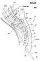
- the percutaneous pathwayis generally axially aligned with an anterior axial instrumentation/fusion line (AAIFL) or a posterior axial instrumentation/fusion line (PAIFL) extending from the respective anterior or posterior target point through at least one sacral vertebral body and one or more lumbar vertebral body in the cephalad direction and visualized by radiographic or fluoroscopic equipment.
- the AAIFL and PAIFLfollow the curvature of the vertebral bodies, although the AAIFL can be straight or relatively straight, depending on the number of vertebrae that the AAIFL is extended through.
- anterior or posterior percutaneous pathway so formedenables introduction of further tools and instruments for forming an anterior or posterior percutaneous tract extending from the skin incision to the respective anterior or posterior target point of the sacral surface or, in some embodiments, the cephalad end of a pilot hole over which or through which further instruments are introduced.
- the “anterior, presacral, percutaneous tract” disclosed hereinextends through the “presacral space” anterior to the sacrum.
- the anterior or posterior percutaneous tractis preferably used to bore one or more respective anterior or posterior TASIF bore in the cephalad direction through one or more lumbar vertebral bodies and intervening discs, if present.
- a single anterior or posterior TASIF boreis preferably aligned axially with the respective visualized AAIFL or PAIFL, and plural anterior or posterior TASIF bores are preferably aligned in parallel with the respective visualized AAIFL or PAIFL.
- Introduction of spinal implants and instruments for performing discectomies and/or disc and/or vertebral body augmentationis enabled by the provision of the percutaneous pathway in accordance with the present invention and formation of the anterior or posterior TASIF bore(s).
- the posterior percutaneous tractpreferably extends from a posterior skin incision into the posterior sacrum to a posterior target point exposed by a laminectomy.
- This posterior percutaneous tracthas a tract axis aligned with the visualized PAIFL to provide working space, exposure of the sacrum, and alignment of the boring tool with the visualized PAIFL.
- the posterior percutaneous tractcan take the form of a lumen of a tract sheath introduced through the percutaneous pathway or a guidewire whereby the guidewire provides a percutaneous tract for over the wire passage extending from the skin incision to the posterior target point and aligned with the visualized PAIFL.
- Either or both of the tract sheath or guidewirecan comprise distal fixation mechanisms that enable fixation to the sacral vertebral surface at the posterior target point for through the sheath or over the wire introduction of boring tools or other instruments.
- a pilot hole for each such posterior TASIF boreis optionally bored along or parallel with the visualized PAIFL, and the guidewire distal end is affixed to vertebral bone at the cephalad end of the pilot hole to provide the percutaneous tract for guiding a drill or other instrument to form the posterior TASIF bore or conduct discectomies or disc or vertebral bone augmentation.
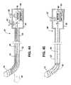
- Certain of the surgical toolstake the form of elongated solid body members extending from proximal to distal ends thereof. Such solid body members may be used in combination with or sequentially with elongated hollow body members. Certain of these solid body and hollow body members can have distal fixation mechanisms for attachment to bone and/or can be angles to be aligned with and bear against sacral bone.
- the anterior percutaneous pathwayis preferably accomplished employing an elongated guide member that is introduced through the skin incision and advanced against the anterior sacrum through the presacral space until the guide member distal end is located at the anterior target point.
- the posterior visceraare pushed aside as the guide member is advanced through presacral space and axially aligned with the AAIFL at the anterior target point of the anterior sacral surface.
- the guide membermay take a variety of forms including a blunt tip rod or a guide assembly of an inner occluder and an outer tubular member fitted together having a tubular member lumen receiving the occluder.
- the occludermay take the form of a solid body member, e.g., an obdurator, a stylet, a guidewire or the like, and the tubular member may take the form of a needle, a trocar, a catheter or the like.
- Either or both of the inner occluder and outer tubular membermay comprise distal fixation mechanisms that enable fixation to the sacral vertebral surface at the anterior target point and/or at the cephalad end of a pilot hole for each such anterior TASIF bore optionally bored along or parallel with the visualized AAIFL.
- the occludercan be employed to blunt the tip of the outer tubular member during introduction to the anterior target point, if the outer tubular member comprises a distal tip fixation mechanism that would otherwise prematurely engage the sacral bone.
- the occludercan have a distal tip fixation mechanism and be retracted within the outer tubular member to prevent its premature attachment to sacral bone during introduction to the anterior target point.
- the anterior, presacral, percutaneous tractcan take the form of the lumen of the outer tubular member upon removal of the occluder.
- the anterior percutaneous pathwaycan be expanded to form the anterior, presacral, percutaneous tract through the patient's anterior presacral space having a tract axis aligned with the visualized AAIFL to provide working space and exposure of the sacrum.
- a guidewire having a distal fixation mechanism(which may comprise the occluder) provides the anterior, presacral, percutaneous tract for over-the-wire passage extending from the skin incision to the target point and aligned with the visualized AAIFL.
- the lumen of a further tract sheath introduced through the percutaneous pathwaye.g., over the guidewire or after removal of the guidewire, provides a percutaneous tract for over the wire passage extending from the skin incision to the target point and aligned with the visualized AAIFL.
- the further tract sheathpreferably has a distal tract sheath fixation mechanism and configuration that enables alignment and attachment to the anterior sacral bone at the anterior target point to maintain the tract sheath lumen aligned axially with a the visualized AAIFL.
- tissue surrounding the skin incision and the anterior, presacral, percutaneous pathway through the presacral spacemay optionally be dilated to form an enlarged diameter presacral, percutaneous tract surrounding a guidewire or tubular member and/or to accommodate the insertion of a tract sheath over the guidewire. Dilation can be accomplished manually or by use of one or more dilator or dilatation balloon catheter or any tubular device fitted over a previously extended tubular member or guidewire.
- a pilot holecan be bored in axial alignment or parallel with the visualized AAIFL by a boring tool introduced through the outer tubular member lumen for each such anterior TASIF bore bored along or parallel with the visualized AAIFL.
- the guidewire distal end fixation mechanismis then affixed to vertebral bone at the cephalad end of the pilot hole to provide the percutaneous tract for guiding a drill or other instrument to form the anterior TASIF bore or conduct discectomies or disc or vertebral bone augmentation.
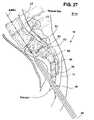
- the junction of S 1 and S 2is located through a presacral, percutaneous tract posterior to the rectum and extending from a skin incision adjacent the coccyx.
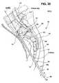
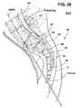
- a relatively straight anterior TASIF axial bore into at least L 5can be formed in the vertebral column accessed via the anterior, presacral, percutaneous tract to receive a TASIF implant or interventional tools inserted through the anterior, presacral, percutaneous tract.
- the anterior TASIF axial borecan also be curved to follow the curvature of the vertebrae L 4 , L 3 , et seq. in the cephalad direction following a visualized, curved, AAIFL extending therethrough.
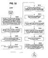
- a preferred posterior TASIF approachthe posterior sacrum is exposed, a laminectomy is performed at S 2 , and the posterior percutaneous tract is formed using one of the above-summarized procedures and percutaneous tract tool sets.
- a curved axial boreis then made upwardly through S 2 , S 1 and into at least L 5 and optionally extended and curved to follow the curvature of the vertebrae L 4 , L 3 , et seq. in the cephalad direction.
- a curved TASIF implant or rodcan be inserted into the TASIF axial bore to bridge the vertebrae and the intervening discs, if present.
- the various embodiments of the present inventionprovide access to anterior and posterior target points of the anterior or posterior sacrum preparatory to forming anterior or posterior TASIF bores that extend in the cephalad direction and can be employed to introduce instruments for treatment of vertebral bodies, intervertebral discs and introduction of axially aligned spinal implants as described in further detail in the above-referenced provisional application No. 60/182,748.
- multiple boresmay be made side-by-side to receive multiple spinal implants.
- the access procedures for forming the anterior or posterior percutaneous tract and the subsequently conducted surgical repair and/or implantation proceduresare minimally invasive and requires a short, if any, post-implantation hospitalization and recovery period and reduced discomfort to the patient.
- the access proceduresavoid the muscle stripping required to access the vertebrae and/or discs or removal of strong anterior vertebral body bone and intervening discs attendant to the conventional lateral surgical approaches described above
- the anterior and posterior TASIF approachesalso allow disc surgery or disc augmentation through the TASIF bore or pilot hole of all discs traversed by the TASIF axial bore or pilot hole in a minimally invasive manner.
- these approachescan be employed a minimally invasive manner to perform vertebroblasty of the vertebrae traversed by the TASIF axial bore or pilot hole to augment the vertebral bone in cases of compression fracture of the vertebral bone.
- Vertebroblastyis procedure for augmentation of collapsed vertebral bodies by pumped in materials, e.g., bone cement. In the past, it has been accomplished through a lateral approach of a needle into a single vertebral body and pumping the cement through the needle lumen.
- the present inventionallows larger diameter access to multiple vertebral bodies through the axial approach.
- the present inventionfurther enables use of a number of differing types of TASIF implants or rods that can be inserted into the TASIF axial bore or bores.
- Such implantable vertebral prosthesesalign, strengthen, and fuse the adjacent vertebrae particularly in the lumbar region of the spinal column.
- the elongated, axially extending TASIF implants or rods implanted using the percutaneous tracts formed in accordance with the present inventionreinforce the relatively strong anterior vertebral bodies and should prevent potentially damaging telescoping of adjacent vertebrae.
- the TASIF spinal implants or rodscan be implanted in accordance with the present invention in a less traumatic manner than conventional lateral exposure and placement of conventional vertebral prostheses, and the need to implant screws or extend wires laterally through the vertebral bodies and a rod or rods is eliminated.
- the TASIF implants or rods that can be implantedinherently possess a low profile and would usually not be felt by the patient after healing.
- anterior or posterior TASIF pilot hole or axial boremay also be used to receive pain relief stimulation electrodes coupled through leads to implantable pulse generators for providing electrical stimulation of the bone and adjoining nerves for pain relief and/or to stimulate bone growth.
- Other therapeutic spinal implantscan be implanted therein to elute drugs or analgesics or emit radiation for treatment of various diseases or pain syndromes.
- FIGS. 1–3are lateral, posterior and anterior views of the lumbar and sacral portion of the spinal column depicting the visualized PAIFL and AAIFL extending cephalad and axially from the posterior laminectomy site and the anterior target point, respectively;
- FIG. 4is a sagittal caudal view of lumbar vertebrae depicting a TASIF spinal implant or rod within a TASIF axial bore formed following the visualized PAIFL or AAIFL of FIGS. 1–3 ;
- FIG. 5is a sagittal caudal view of lumbar vertebrae depicting a plurality, e.g., 2, TASIF spinal implants or rods within a like plurality of TASIF axial bores formed in parallel with the visualized PAIFL or AAIFL of FIGS. 1–3 ;
- FIG. 6is a simplified flow chart showing the principal surgical preparation steps of percutaneously accessing a posterior or anterior target point of the sacrum and forming a percutaneous tract following the visualized PAIFL or AAIFL of FIGS. 1–3 as well as subsequent steps of forming the TASIF bore(s) for treatment of accessed vertebral bodies and intervening discs and/or implantation of spinal implants therein;
- FIGS. 7–9depict the principal surgical preparation and implantation steps of forming a posterior percutaneous tract enabling access for forming one or more posterior TASIF axial bore following the visualized PAIFL of FIGS. 1 and 2 ;
- FIGS. 10 and 11are views of embodiments of a motor driven, canted tip, drill for drilling a posterior pilot hole following the visualized PAIFL of FIGS. 1 and 2 ;
- FIG. 12is a flow chart expanding upon step S 100 of FIG. 6 showing the principal surgical preparation steps of forming various types of anterior, presacral, percutaneous tracts axially aligned with the visualized AAIFL of FIGS. 1 and 3 through presacral space posterior to the patient's rectum;
- FIGS. 13–21illustrate various tools employed in various combinations and sequence for forming the various types of anterior, presacral, percutaneous tracts used in performing the anterior tract forming steps set forth in FIG. 12 ;
- FIGS. 22–26illustrate the use of certain tools of FIGS. 13–17 following steps of FIG. 12 to form anterior, presacral, percutaneous tracts through the presacral space that are axially aligned with the visualized AAIFL of FIGS. 1 and 3 either surrounding inner occluder or an outer tubular member of a guide assembly;
- FIG. 27illustrates the use of one form of dilator(s) shown in FIGS. 20–21 to dilate the presacral space and expand the anterior, presacral, percutaneous tract in accordance with optional steps S 116 and S 118 of FIG. 12 ;
- FIGS. 28–29illustrate insertion of an enlarged tubular anterior tract sheath illustrated in FIG. 13 having an angled distal end through the dilated presacral tissue to form an enlarged anterior, presacral, percutaneous tract comprising the anterior tract sheath lumen in accordance with optional steps S 120 and S 122 of FIG. 12 ;
- FIGS. 30–31illustrate insertion of an enlarged tubular anterior tract sheath having a distal fixation mechanism through the dilated presacral tissue to form an enlarged anterior, presacral, percutaneous tract comprising the anterior tract sheath lumen in accordance with optional steps S 120 and S 122 of FIG. 12 ;
- FIG. 32is a flow chart showing particular steps of attaching a guidewire to the anterior target point to form an anterior, presacral, percutaneous tract maintained in axial alignment with the AAIFL;
- FIG. 33is a flow chart showing alternative particular steps of attaching a guidewire to the anterior target point to form an anterior, presacral, percutaneous tract maintained in axial alignment with the AAIFL;
- FIG. 34is a flow chart showing steps of forming a pilot hole tracking the AAIFL and attaching a guidewire to the cephalad end of the pilot hole to form an anterior, presacral, percutaneous tract about the guidewire maintained in axial alignment with the AAIFL;
- FIGS. 35–39illustrate certain of the steps of FIG. 34 ;
- FIG. 40is a flow chart showing steps of dilating the presacral tissue around the affixed guidewire of FIG. 39 and the insertion of an enlarged tubular anterior tract sheath through the dilated presacral space to form the anterior, presacral, percutaneous tract comprising the anterior tract sheath lumen;
- FIGS. 41–43illustrate certain of the steps of FIG. 40 ;
- FIG. 44is a view of one form of pilot hole or TASIF axial bore hole boring tool for forming a pilot hole or TASIF axial bore that is straight or curved in whole or in part;
- FIG. 45is a view of another form of pilot hole or TASIF axial bore hole boring tool for forming a pilot hole or TASIF axial bore that is straight or curved in whole or in part;
- FIG. 46illustrates the step of forming an anterior TASIF axial bore hole using an enlarged diameter drill bit.
- the preferred embodiments of the inventioninvolve methods and apparatus including surgical tool sets for forming anterior and posterior percutaneous tracts for accessing anterior and posterior target points of the sacrum in alignment with the visualized AAIFL and PAIFL.
- pilot holesmay be bored in the cephalad direction through one or more sacral and lumbar vertebral bodies in alignment with the visualized AAIFL and PAIFL and used as part of the anterior and posterior percutaneous tracts.
- the pilot holes of the anterior and posterior percutaneous tractscan be used to introduce instruments to inspect and/or perform therapies upon the vertebral bodies or intervening discs.
- the posterior or anterior pilot holemay optionally be used as the posterior or anterior TASIF axial bore, respectively, axially aligned with the PAIFL or AAIFL, respectively, to receive spinal implants of various types.
- the access to the anterior and posterior target points or pilot holes offered by the anterior and posterior percutaneous tractscan be used to form larger diameter or particularly shaped TASIF bores, which are also referred to as TASF bores in the above-reference parent provisional application No. 60/182,748.
- the enlarged diameter or otherwise shaped TASIF borescan be used to introduce instruments to inspect and/or perform therapies upon the vertebral bodies or intervening discs and/or insert spinal implants as set forth in the above-referenced parent provisional application No. 60/182,748 and further described herein.
- FIGS. 1–6The following description of FIGS. 1–6 is taken from the above-referenced parent provisional application No. 60/182,748.
- the acronyms TASF, AAFL, and PAFLare changed to TASIF, AAIFL and PAIFL in this application to explicitly acknowledge that instruments can be introduced for inspection or treatments in addition to the fusion and fixation provided by spinal implants that may be inserted into the axial bores or pilot holes.
- FIGS. 1–3schematically illustrate the anterior and posterior TASIF surgical approaches in relation to the lumbar region of the spinal column
- FIGS. 4–5illustrate the location of the TASIF implant or pair of TASIF implants within a corresponding TASIF axial bore 22 , 152 or pair of TASIF axial bores 22 1 , 152 1 , and 22 2 , 152 2
- Preferred TASIF surgical approaches for providing anterior and posterior trans-sacral access depicted in FIGS. 1–3 and preparing the TASIF axial bores 22 , 152 and 22 1 , 152 1 / 22 2 , 152 2 shown in FIGS. 4 and 5are illustrated in further drawings.
- TASIF implants or rods usable in the TASIF axial bores 22 , 152 and 22 1 , 152 1 / 22 2 , 152 2 of FIGS. 4 and 5are depicted in the above-referenced parent provisional application No. 60/182,748.
- Two TASIF axial bores and spinal implants or rodsare shown in FIG. 5 to illustrate that a plurality, that is two or more, of the same may be formed and/or employed in side by side relation parallel with the AAIFL or PAIFL.
- FIG. 1The lower regions of the spinal column comprising the coccyx, fused sacral vertebrae S 1 –S 5 forming the sacrum, and the lumbar vertebrae L 1 –L 5 described above are depicted in a lateral view in FIG. 1 .
- the series of adjacent vertebrae located within the human lumbar and sacral spinehave an anterior aspect, a posterior aspect and an axial aspect, and the lumbar vertebrae are separated by intact or damaged spinal discs labeled D 1 –D 5 in FIG. 1 .
- FIGS. 2 and 3depict the posterior and anterior view of the sacrum and coccyx.
- the method and apparatus for fusing at least L 4 and L 5 and optionally performing a discectomy of D 5 and/or D 4involves accessing an anterior sacral position, e.g. an anterior target point at the junction of S 1 and S 2 depicted in FIGS. 1 and 3 , or a posterior sacral position, e.g. a posterior laminectomy site of S 2 depicted in FIGS. 1 and 2 .
- an anterior sacral positione.g. an anterior target point at the junction of S 1 and S 2 depicted in FIGS. 1 and 3
- a posterior sacral positione.g. a posterior laminectomy site of S 2 depicted in FIGS. 1 and 2 .
- One (or more) visualized, imaginary, axial instrumentation/fusion lineextends cephalad and axially in the axial aspect through the series of adjacent vertebral bodies to be fused, L 4 and L 5 in this illustrated example.
- the visualized AAIFL through L 4 , D 4 , L 5 and D 5extends relatively straight from the anterior target point along S 1 depicted in FIGS. 1 and 3 , but may be curved as to follow the curvature of the spinal column in the cephalad direction.
- the visualized PAIFLextends in the cephalad direction with more pronounced curvature from the posterior laminectomy site of S 2 depicted in FIGS. 1 and 2 .
- FIG. 6depicts, in general terms, the surgical steps of accessing the anterior or posterior sacral positions illustrated in FIGS. 1–3 (S 100 ) forming posterior and anterior TASIF axial bores (S 200 ), optionally inspecting the discs and vertebral bodies, performing disc removal, disc augmentation, and vertebral bone reinforcement (S 300 ), and implanting posterior and anterior spinal implants and rods (S 400 ) in a simplified manner.
- step S 100access to the anterior or posterior sacral position, that is the anterior target point of FIG. 3 or the posterior laminectomy site of FIG. 2 is obtained, and the anterior or posterior sacral position is penetrated to provide a starting point for each axial bore that is to be created.
- an axial boreis bored from each point of penetration extending along either the PAIFL or AAIFL cephalad and axially through the vertebral bodies of the series of adjacent vertebrae and any intervening spinal discs (S 200 ).
- the axial boremay be visually inspected using an endoscope to determine if the procedures of step S 300 should be performed.
- Discoscopy or discectomy or disc augmentation of an intervening disc or discs or vertebroblastymay be performed through the axial bore (S 300 ).
- an elongated TASIF spinal implant or rodis inserted into each axial bore to extend cephalad and axially through the vertebral bodies of the series of adjacent vertebrae and any intervening spinal discs (S 400 ).
- Other types of spinal implants for delivering therapies or alleviating pain as described abovemay be implanted substitution for step S 400 .
- step S 100 in the anterior and/or posterior TASIF proceduresmay involve drilling a pilot hole, smaller in diameter than the TASIF axial bore, that tracks the AAIFL and/or PAIFL in order to complete the formation of the anterior and/or posterior percutaneous tracts.
- Step S 300may optionally be completed through the AAIFL/PAIFL pilot hole following step S 100 , rather than following the enlargement of the pilot hole to form the TASIF axial bore in step S 200 .
- Step S 100 of FIG. 6is performed in the posterior TASIF procedure as follows. It is expected that the patient 10 , depicted in FIG. 7 in a partial side cross-section view, will lie prone on a surgical table having reverse lordosis support.
- An imaging system(not shown), which may be an MRI scanner, a CT scanner or preferably a bi-plane fluoroscopy machine, is employed first to show the spinal structure and adjacent tissues, vessels and nerves for visualizing the PAIFL through the visible landmarks of the sacrum and lumbar vertebrae. Then, the imaging system is employed during the surgical creation of the posterior TASIF axial bore to ensure that it remains within the vertebral bodies and intervening discs following the PAIFL and does not stray anteriorly, posteriorly or laterally therefrom.
- step S 100depicted in FIG. 7 , an incision is made in the patient's skin 12 over the posterior sacral surface of S 2 and a posterior tract 18 is formed through the subcutaneous tissue to expose the posteriorly extending, bony ridge of the posterior sacral surface.
- a small laminectomy 14is performed through the posterior ridge of the sacrum inferior. The thecal sac and nerve roots that are exposed by the laminectomy are gently retracted, and the terminal portion of the spinal canal is exposed.
- a posterior percutaneous tractis provided that enables the precise stabilization and positioning of pilot hole boring and/or posterior TASIF axial bore forming tools for boring the pilot hole and/or posterior TASIF axial bore.
- the posterior percutaneous tractcan take the form of a guidewire 80 depicted in FIG. 8 that is affixed at its distal end to the sacrum at the posterior target point.
- the distal fixation mechanismmay comprise a distal screw-in tip 82 as shown in FIG. 8 or may take other forms, e.g., the hook or barb 82 ′ depicted in FIGS. 18 and 19 .
- a proximal, removable, guidewire handle 81is used to rotate the guidewire 80 to screw distal screw-in tip 82 into and out of the sacral bone, and is removed at other times.
- the guidewire 80then provides a percutaneous tract extending from the skin incision 18 to the posterior target point that is aligned with the visualized PAIFL
- the guidewire formed posterior percutaneous tractprovides over-the-wire guidance of a drill or boring instrument for boring a pilot hole or posterior TASIF axial bore passage
- the characteristics and alternative forms that the guidewire 80 may takeare described further below in reference to FIG. 13 .
- the guidewire 80may be introduced through the percutaneous pathway as an occluder within the lumen of an outer, stiffer, tubular member in the manner described below in the anterior approach in reference to FIG. 25 .
- the distal screw-in tip 82can then be advanced distally, and screwed in while the outer tubular member confines the guidewire shaft. Then the outer tubular member is removed.
- the posterior percutaneous tractcan also take the form of a lumen of a posterior tract sheath introduced through the posterior percutaneous pathway.
- a posterior tract sheath 30is depicted in FIG. 9 having a tract sheath lumen 32 extending from a proximal sheath end 34 to a distal sheath end 36 .
- the distal sheath end 36is formed with a distal sheath end fixation mechanism for anchoring the distal sheath end 36 to the sacrum at the posterior surface of S 2 , for example.
- the depicted distal sheath end fixation mechanismcomprises a threaded tip that can be screwed into bone, although a starting hole may have to be first formed so that the screw threads can be advanced and the posterior tract sheath can be firmly fixed to the sacrum.
- the tract sheath lumen 32provides a posterior percutaneous tract that is axially aligned to starting point of the visualized PAIFL 20 , and the tract sheath 30 then functions as a boring tool or drill guide to assist in keeping the boring tool or drill on tract.
- FIG. 10depicts the use of the posterior tract sheath 30 with a drill 40 for drilling or boring a posterior pilot hole 38 from the posterior target point at S 2 along the visualized PAIFL 20 prior to boring the posterior TASIF bore.
- This two step approachfurther involves the insertion of the guidewire through the pilot hole 38 and affixation of the guidewire distal fixation mechanism into the vertebral body bone at the cephalad end of the pilot hole 38 as shown in FIG. 11 .
- the guidewire 80 affixed to the vertebral bone at the cephalad end of the pilot holeprovides the posterior percutaneous tract for guiding a drill or other instrument to form an enlarged posterior TASIF bore or for conducting discectomies or disc or vertebral bone augmentation.
- the tract sheath 30may provide the starting point and guide the direct drilling or boring of the posterior TASIF axial bore(s) without forming the pilot hole and employing the guidewire 80 in the manner depicted in FIG. 11 .
- the posterior TASIF pilot hole 38extends through the centers of two or more vertebral bodies L 4 , L 5 and intervening discs anterior to and extending in parallel with the thecal sac (also shown in FIG. 4 , for example).
- a drill bit 44 at the distal end of a directional drill sheath 42 of a drill 40 or 40 ′is carefully advanced using bi-plane fluoroscopic visualization (or other visualization) through the sheath lumen 32 operating as a drill guide.
- the drill drive shaft 46 , 46 ′ within the drill sheath 42is rotated by the drill motor to rotate the drill bit 44 , 44 ′ as it is advanced under fluoroscopic observation along the visualized PAIFL 20 and form the curved posterior TASIF pilot hole 38 .
- Suitable exemplary directional drills 40 and 40 ′are schematically depicted in FIGS. 44 and 45 .
- the drill 40 of FIG. 44comprises a drill motor housing 50 coupled with drill sheath 42 enclosing the drill drive shaft 46 .
- the drill motor housing 50includes a motor 48 powered by a battery 54 .
- the drill motor 48is coupled to the battery 54 by manipulation of a power switch 52 to rotate the drive shaft 46 and drill bit 44 of drill 40 .
- a pull wire 45extends through a pull wire lumen 49 extending along one side of the sheath 42 between its distal end and a tip curvature control 47 on drill motor housing 50 .
- the distal end portion of drill sheath 42is flexible, and retraction of pull wire 45 by manipulation of tip curvature control 47 causes the distal end portion of drill sheath 42 to assume a curvature from the straight configuration as shown in phantom lines in FIG. 44 .
- the surgeoncan manipulate tip curvature control 47 to control the curvature of the distal end portion of drill sheath 42 and the TASIF axial bore 22 .
- the drill 40 ′ of FIG. 45comprises a drill motor housing 50 ′ coupled with drill sheath 42 ′ enclosing the drill drive shaft 46 ′.
- the drill motor housing 50 ′includes a battery 54 ′ and motor 48 ′ that is turned on by manipulation of a power switch 52 ′ to rotate the drive shaft 46 ′ and drill bit 44 ′ of drill 40 ′.
- the distal end portion 56 of drill sheath 42is pre-curved or canted at about 20°, for example, providing an eccentric drill bit 44 ′.
- the eccentric drill bit 44 ′has an inherent tendency to “veer” in the direction of rotation of the drill bit. Rotating the drill sheath 42 ′ during advancement along the visualized axial instrumentation/fusion line 20 causes it to form the TASIF pilot hole 38 that follows the curved PAIFL of FIG. 1 .
- the drilling of the posterior TASIF axial bore 22may be undertaken in sequential steps of first drilling a small diameter pilot hole along the PAIFL 20 using the drill 40 or 40 ′, inserting a guidewire through the pilot hole, and then enlarging the pilot hole to form the curved posterior TASIF axial bore.
- the posterior TASIF axial bore forming tool setmay be similar to the anterior TASIF axial bore forming steps and tools described below.
- a small diameter drill bit and drill shaft(e.g. 3.0 mm diameter) is used to first drill a small diameter pilot hole 38 following the imaginary, visualized PAIFL 20 through S 1 , L 5 and L 4 .
- the drill bit and shaftare removed, and the guidewire 80 having the threaded distal screw-in tip 82 is advanced through the pilot hole 38 and screwed into to the cephalad end of the pilot hole 38 and into the L 4 vertebral body.
- An over-the-wire bore enlarging toolis fitted over the proximal end of the guidewire and manually or mechanically rotated and advanced along it in the manner described below with regard to the formation of the larger diameter, e.g. a 10.0 mm diameter, anterior TASIF axial bore.
- the pilot hole diameteris enlarged to form the anterior TASIF axial bore, and the enlarging tool is then removed.
- the longitudinal, curved, posterior TASIF axial bore(s) 22(shown in FIGS. 4 and 5 ) formed in step S 200 of FIG. 6 starts in the sacrum at the posterior target point or position exposed by the laminectomy and extends upwardly or cephalad through the vertebral body of S 1 or S 2 and through the cephalad vertebral bodies including L 5 and L 4 and the intervening discs denoted D 4 and D 5 in FIG. 1 .
- Discs D 4 and D 5are usually damaged or have degenerated between lumbar spine vertebrae and cause the pain experienced by patients requiring intervention and fusion of the vertebrae.
- An inspection of the vertebral bodies and discs along the sides of the TASIF axial bore 22can be made using an elongated endoscope inserted through the TASIF axial bore or the pilot hole 38 if one is formed.
- a discectomy or disc augmentation and/or vertebroblastymay be performed pursuant to step S 300 of FIG. 6 through the posterior TASIF axial bore 22 or pilot hole 38 and laminectomy site to relieve the patient's symptoms and aid in the fusion achieved by-the posterior spinal implant or rod.
- FIG. 12expands upon step S 100 of FIG. 6 showing the principal surgical preparation steps of forming an anterior, presacral, percutaneous tract 26 axially aligned with the visualized AAIFL of FIGS. 1 and 3 through presacral space 24 posterior to the patient's rectum.
- the anterior tract forming steps of FIG. 12are performed using certain of the tools of an anterior tract forming tool set 60 that is shown in FIG. 13 and optionally using additional or alternative tools illustrated in FIGS. 14–21 .
- Certain additional or alternative surgical procedure stepsare set forth in FIGS. 32–34 and 40 .
- the remaining figuresillustrate the surgical tools as used in certain of these steps.
- Elongated solid body membersin medical terminology include relatively stiff or flexible needles of small diameter typically used to penetrate tissue, wire stylets typically used within electrical medical leads or catheters to straighten, stiffen, or impart a curved shape to the catheter, guidewires that are used to traverse body vessel lumens and access remote points therein (certain hollow body guidewires have lumens for a number of uses), and obdurators.
- Obduratorsare typically formed as rods provided in various diameters with blunt distal tips that can be manipulated to penetrate, separate or manipulate tissue without cutting or other damage.
- guidewireis employed herein to embrace any such solid body member (guidewire type) that can be employed to perform the functions of over-the-wire delivery and guidance described herein unless the exclusive use of a given one of such solid body members is explicitly stated.
- Such solid body membersmay be stiff or flexible and may include distal fixation mechanisms.
- Certain others of the surgical toolstake the form of hollow body, tubular members having lumens extending from proximal to distal ends thereof.
- Such hollow body, tubular memberscan take the form of medical catheters, medical cannulas, medical tubes, hollow needles, trocars, sheaths, and the like.
- Such hollow body tubular members employed in various embodiments of the present inventionmay be stiff or flexible and may include distal fixation mechanisms.
- occluderis employed herein to comprise any form of elongated tool that is inserted into a tubular member lumen and that entirely or partly occludes the lumen of the tubular member and may extend distally from the tubular member distal end.
- Any of the guidewire typescan function as an occluder of the lumen of any of the tubular member types.
- the anterior tract tool set 60 depicted in FIG. 13 and variations and modifications thereof shown in FIGS. 14–19include a number of surgical tools that can be used in combination and over or through one another to form or enlarge the anterior percutaneous tract.
- the anterior percutaneous tractcan be enlarged using one or more of the dilators depicted in FIGS. 20 and 21 .
- a guide assembly that is employed as shown in FIGS. 22 and 23is preferably formed of a rounded or blunt tip occluder 62 fitted through the lumen of a percutaneous tubular member 70 .
- a guidewire 80is also included in tool set 60 that can be inserted through and also function as an occluder of the lumen 74 of percutaneous tubular member 70 .
- the percutaneous tubular member 70preferably comprises a 9–18 gauge needle shaft 72 enclosing a needle lumen 74 and extending between a beveled needle distal end 76 and a needle proximal end hub 78 .
- the tubular member lumen 74is dimensioned in diameter to receive the blunt tip occluder shaft 68 and the guidewire 80 .
- the tubular member shaft 72is dimensioned in length to allow the distal end blunt tip 64 to protrude from the distal end opening of the tubular member lumen 74 when the occluder proximal end 66 abuts the needle proximal hub 78 as shown in FIGS. 22 and 23 .
- the needle proximal end hub 78is preferably removable from the needle shaft 72 to enable passage of other tubular members over needle shaft 72 .
- the guidewire 80 illustrated in FIG. 13has a threaded screw-in tip 82 having screw threads that are adapted to be screwed into vertebral bone at various steps of the process of forming the anterior tract 26 , the TASIF axial bore, and the insertion of an anterior TASIF spinal implant over the guidewire 80 as described below.
- the guidewire 80is preferably formed of a kink resistant stainless steel or nickel-titanium alloy wire having an outer diameter of about 0.038 inches to 0.120 inches (about 1.0–3.0 mm) and a length of 100 cm or less.
- the threaded screw-in tip 82is formed at the distal end of the guidewire 80 , and a removable knob 81 is attached over the proximal end of the guidewire 80 .
- the threaded screw-in tip 82can be rotated by rotation of the proximal knob 81 in order to screw it into a vertebral body at the anterior target point and at the cephalad end of the anterior TASIF pilot hole as described below. Once the threaded screw-in tip is fixed, the proximal knob 81 can be removed to allow tools and devices to be advanced from its free proximal end over the guidewire body toward the threaded screw-in tip 82 fixed to the bone.
- the guidewire distal end fixation mechanism 82may be configured as a screw-in tip as shown in FIG. 13 or as a hook as shown in FIGS. 18 and 19 or simply of a sharpened tip that can be stabbed into the sacral bone at the anterior target point. If the guidewire 80 is employed as an occluder of the guide assembly, then the guidewire distal end fixation mechanism 82 or 82 ′ is retracted into the lumen tubular member lumen 74 as shown in FIG. 18 and described below in reference to FIG. 33 . The distal guidewire fixation mechanism 82 or 82 ′ advanced out as shown in FIG. 19 and attached to the sacral bone when the outer tubular member distal end 76 or 76 ′ is located at the anterior target point of the sacrum.
- the percutaneous tubular member distal endcan be shaped in a variety of ways and can be formed with a 30 °–80° angled or beveled tip 76 or a 90° blunt 76 ′ as shown in FIGS. 13 , 14 , 18 , 19 , 22 , 23 and 25 .
- the percutaneous tubular member distal endcan itself be sharpened, e.g., by the bevel as shown in FIG. 13 , or blunted as shown in FIG. 14 .
- the percutaneous tubular member lumenis preferably occluded by the blunt tip inner occluder which protrudes distally from the distal end opening of the tubular member 70 FIGS. 14–17 and blunts the percutaneous tubular member distal end enabling it to be advanced along the anterior surface of the sacral bone as described below.
- the percutaneous tubular member distal endcan be shaped in a variety of ways to incorporate a variety of tubular member distal tip fixation mechanisms as shown in FIGS. 15–17 and 24 , for example.
- the blunt tip obdurator 60can also be employed to blunt the percutaneous tubular member distal end fixation mechanisms 76 ′, 76 ′′ and 76 ′′′, for example, enabling the guide assembly distal end to be advanced along the anterior surface of the sacral bone as described below.
- One form of the anterior, presacral, percutaneous tract axially aligned with the visualized AAIFL of FIGS. 1 and 3 through presacral space posterior to the patient's rectumcomprises the presacral space surrounding the percutaneous tubular member 70 or the guidewire 80 that is introduced as an occluder or after removal of the blunt tip occluder 62 through the percutaneous tubular member lumen in accordance with steps S 102 –S 114 of FIG. 12 .
- FIGS. 22–26illustrate the exemplary use of certain ones of the tools shown in FIGS. 13–17 and described above following steps of FIG. 12 to form the anterior, presacral, percutaneous tract 26 .
- step S 102an anterior skin incision 28 about 5–10 mm long is made at an access point that is cephalad to the anus and alongside or inferior to the tip of the coccyx to avoid penetrating the rectal wall.
- the skin incision 28can be made approximately 2.0 cm lateral and 2.0 cm cephalad to the tip of the coccyx.
- step S 104the blunt tip occluder 62 is fitted within tubular member lumen 74 to form the guide assembly as shown in FIG. 14 , for example.
- the guide assemblyis inserted through the anterior incision 28 and advanced carefully in step S 106 under anterior and lateral fluoroscopic imaging visualization posterior to the rectum and through the fatty tissue of the presacral space 24 until the blunt distal end 64 contacts the anterior surface of the sacrum.
- step S 108also shown in FIG.
- the blunt distal end 64 protruding from the tubular member distal end 76is advanced or “walked” cephalad along the anterior sacrum under fluoroscopic or CT imaging visualization in the presacral space 24 toward the anterior target point anterior to the body of S 2 .
- careis taken to ensure that the tubular member shaft 72 displaces but does not perforate the rectum and to ensure that nerves and arteries traversing the sacrum and presacral space 24 are not damaged.
- the rectumcan be distended with air so that its posterior wall can be visualized fluoroscopically or other visualization system.
- step S 110after the anterior target point is reached, the guide assembly is axially aligned with the AAIFL.
- step S 112either the occluder or the tubular member distal end fixation mechanism is manipulated to affix the occluder or tubular member to the sacrum at the anterior target point.
- the blunt tip occluder 62is retracted within the tubular member lumen 74
- the tubular member angled distal end 76is oriented to the angle of the anterior sacrum at the anterior target point as shown in FIG. 25 .
- step S 112if the tubular member distal end comprises a distal end fixation mechanism 76 ′′, 76 ′′′ or 76 ′′′′, then tubular member distal end is advanced to fix the fixation mechanism to sacral bone as shown in FIG. 24 .
- step S 114the occluder is removed from the tubular member lumen 74 , as also shown in FIG. 24 .
- the percutaneous, presacral, percutaneous tractcomprises the presacral space surrounding the tubular member affixed to be axially aligned with the visualized AAIFL so that further tools can be introduced over or alongside the affixed tubular member.
- the elongated tubular member 70may be inflexible as a steel needle or flexible as a small diameter catheter but having sufficient column strength to allow torque or axially applied force to be transmitted to its distal end to affix the distal fixation mechanism into sacral bone.
- the proximal hub 78is removable to allow an effective over-the-wire introduction of other tools described further below.
- the guidewire distal fixation mechanism 82 , 82 ′is operated in step S 112 to fix it to the sacral bone as shown, for example, in FIG. 25 , and described above.
- the guidewire knob 81is rotated to screw the distal screw-in tip 82 into the vertebral bone, and the guidewire knob 81 is pulled off the proximal end of the guidewire 80 .
- the tubular member 70is retracted in step S 114 , leaving the guidewire 80 , 80 ′ axially aligned with the visualized AAIFL as shown in FIG. 26 .
- the percutaneous, presacral, percutaneous tractcomprises the presacral space surrounding the guidewire affixed to be axially aligned with the visualized AAIFL so that further tools can be introduced over or alongside the affixed guidewire.
- the guidewiremay be inflexible as a steel needle or typical surgical obdurator or flexible as a small diameter transvenous or arterial or neural guidewire but having sufficient column strength to allow torque or axially applied force to be transmitted to its distal end to affix the distal fixation mechanism into sacral bone.
- tissue surrounding the skin incision 28 and the presacral space 24 surrounding the extended guidewire 80 or the tubular member 70are dilated in step S 118 and the rectum is pushed aside without perforating it.
- tissue dilatorsthat can be fitted over the extended guidewire 80 or the tubular member 70 are provided in step S 116 .
- tissue dilatorcomprises a balloon catheter 84 illustrated in FIG. 13 . Only the distal portion of the balloon catheter 84 is depicted in FIG. 13 , and it comprises a balloon catheter shaft 86 supporting the expandable balloon 90 and enclosing a balloon shaft lumen 88 and a balloon inflation lumen 92 .
- the balloon catheter shaft lumen 88extends the length of the balloon catheter shaft 86 and terminates at a distal lumen end opening at balloon catheter distal end 94 to allow the guidewire 80 or the tubular member 70 to be received within it.
- the balloon catheter shaft lumen 88facilitates advancement of the balloon catheter shaft 86 over the previously placed guidewire 80 or tubular member 70 while the balloon 90 is deflated.
- the proximal portion of the balloon catheter 84may take any of the conventional forms comprising a hub for passing the guidewire 80 or tubular member 70 and a side port for providing inflation fluid to and removing fluid from the balloon inflation lumen 92 to inflate and deflate the balloon 90 .
- tissue dilators 340 , 350 shown in FIGS. 20–21may also be used, to the extent necessary over the guidewire 80 or tubular member 70 (or over a first anterior tract sheath 120 as described below).
- a single dilator 340 having a gradual taper 342 at the distal endis shown in FIG. 20 to dilate sacral tissue to a first anterior tract diameter.
- a further dilator 350 having a further taper 352is shown in FIG. 21 advanced over the first tissue dilator 340 to further expand the anterior tract diameter.
- the balloon catheter 84 or the dilator(s) 340 , 350is employed to dilate the presacral tissue and to facilitate the optional insertion of the enlarged diameter anterior tract sheath 96 depicted in FIG. 13 or 196 depicted in FIGS. 30 and 31 , in accordance with steps S 120 and S 122 .
- the enlarged diameter anterior tract sheath 96is preferably formed of a thin, relatively rigid, metal or plastic tube that is long enough to extend from the skin incision to the anterior target point through the presacral space and.
- the enlarged diameter anterior tract sheath 96has an anterior tract sheath lumen 98 and a beveled distal end 97 that is at an angle to the sheath axis.
- the enlarged diameter anterior tract sheath 196is formed with an anterior tract sheath distal fixation mechanism 197 of the types employed in the variations of the tubular member 70 described above.
- a distal threaded tip fixation mechanism 197is illustrated in FIGS. 30 and 31 .
- the diameter of the anterior tract sheath lumen 98 , 198is about 15 mm or 36 F, and tract sheath 96 , 196 is about 20 cm long.
- the balloon catheter dilator or the dilators 340 , 350are used over the guidewire or over the tubular member of the guide assembly to center the enlarged diameter anterior tract sheath 96 or 196 and to ease introduction of the enlarged diameter anterior tract sheath 96 or 196 past the posterior abdominal wall.
- the enlarged diameter anterior tract sheath 96is advanced through the presacral space 24 over the inflated balloon 90 or the dilator(s) 340 , 350 , and the beveled distal end 97 is aligned with the typical angle of the anterior surface of the sacrum at the anterior target point as shown in FIG. 28 .
- the anterior tract sheath 96is thereby axially aligned with the AAIFL, and the anterior tract sheath lumen 98 forms the anterior tract 26 shown in FIG. 1 .
- the anterior tract sheath 196is advanced through the presacral space 24 over the inflated balloon 90 or the dilator(s) 340 , 350 as shown in FIG. 30 , and the threaded tip distal end 197 is screwed into the sacral bone at the anterior target point as shown in FIG. 31 .
- the anterior tract sheath 196is thereby axially aligned with the AAIFL, and the anterior tract sheath lumen 198 forms the anterior tract 26 shown in FIG. 1 .
- the balloon 90is then deflated, and the balloon catheter 84 and the guidewire 80 are withdrawn from tract sheath lumen 98 , 198 .
- the dilator(s) 340 , 350 and the guidewire 80are withdrawn from tract sheath lumen 98 .
- the anterior tract 26 of the anterior tract sheath 96 , 196is employed in the steps of FIG. 6 in forming the anterior TASIF axial bore (step S 200 ), the performance of the optional discectomy or disc augmentation (step S 300 ), and in the implantation of the TASIF spinal implant in each such bore (step S 400 ).
- FIG. 32shows alternative particular steps of step S 100 for attaching a guidewire 80 , 80 ′ to the anterior target point to form an anterior, presacral, percutaneous tract maintained in axial alignment with the AAIFL as shown in FIG. 26 .
- the guide assemblycomprising the occluder 62 and tubular member 70 are provided, assembled, advanced and axially aligned with the AAIFL in steps S 504 –S 512 as depicted in FIGS. 22 and 23 .
- the occluder 62is withdrawn from the tubular member lumen 74 in step S 514 , and the guidewire 80 , 80 ′ is provided in step S 516 .
- the guidewire 80 , 80 ′is advanced through the tubular member lumen 74 in step S 516 and S 518 as shown in FIGS. 18 and 25 . Then, the guidewire distal end fixation mechanism 82 , 82 ′ is advanced from the distal end opening of the tubular member lumen 74 and affixed to the sacral bone as shown in FIGS. 19 and 25 . The tubular member 62 is then withdrawn in step S 522 , leaving the guidewire 80 , 80 ′ affixed and extending axially in alignment with the AAIFL through the presacral space. Steps S 116 –S 122 of FIG. 12 can then be optionally performed as described above.
- FIG. 32shows alternative particular steps of attaching a guidewire 80 , 80 ′ to the anterior target point to form an anterior, presacral, percutaneous tract maintained in axial alignment with the AAIFL.
- the guidewire 80 , 80 ′is inserted into the tubular member lumen 74 to form the guide assembly in step S 604 .
- the guidewire distal fixation mechanism 82 , 82 ′is retracted proximally within the tubular member lumen 74 , and the tubular member distal end 76 ′ is preferably blunt as shown in FIG. 18 , for example.
- the guide assemblyis advanced and axially aligned in steps S 606 –S 610 in the manner shown in FIGS. 22 and 23 .
- the guidewire distal end fixation mechanism 82 , 82 ′is advanced from the distal end opening of the tubular member lumen 74 and affixed to the sacral bone as shown in FIGS. 19 and 25 .
- the tubular member 62is then withdrawn in step S 522 , leaving the guidewire 80 , 80 ′ affixed and extending axially in alignment with the AAIFL through the presacral space. Steps S 116 –S 122 of FIG. 12 can then be optionally performed as described above.
- anterior percutaneous tracts 26Three forms of anterior percutaneous tracts 26 are described above following alternative and optional steps of FIG. 12 , that is, over the guidewire 80 , 80 ′ or over the tubular member 70 , 70 ′, 70 ′′, 70 ′′′, 70 ′′′′ (optionally dilated), or through the anterior tract sheath lumen 96 , 196 .
- one or more anterior TASIF axial bores 22 , 22 ′ as shown in FIGS. 4 and 5can be formed through these three forms of anterior percutaneous tracts 26 .
- the anterior TASIF axial bores 22 , 22 ′can be formed using the anterior TASIF axial bore hole boring tools 40 and 40 ′ of FIGS.
- FIGS. 34–39show steps of forming an anterior pilot hole 150 tracking the AAIFL and attaching a guidewire 80 , 80 ′ to the cephalad end of the pilot hole 150 to form an anterior, presacral, percutaneous tract about the guidewire 80 , 80 ′ maintained in axial alignment with the AAIFL.
- the drill bit 112is preferably a 1–5 mm diameter steel drill that is about 30 cm long having drill threads 116 at its sharpened end and is intended to be attached at its other end to a drill to be used to form a pilot hole along AAIFL.
- the intermediate anterior tract sheath 120is preferably formed with a tract sheath distal end fixation mechanism, e.g., a distal screw thread 122 , coupled to the distal end of sheath body 124 .
- the thread-tipped sheath lumen 126extends the length of the thread-tipped sheath 120 through both the distal screw thread 122 and the thread-tipped sheath body 124 .
- the thread-tipped sheath 120is preferably about 25 cm long and has an outer diameter or about 6.0–9.0 mm and an inner lumen diameter of about 3.5–5.5 mm.
- the thread-tipped sheath body 126is preferably formed of a somewhat stiff plastic, e.g.
- the distal screw thread 122is preferably formed of a metal e.g., stainless steel.
- the distal screw thread 122 and distal end of the thread-tipped sheath body 126are preferable thermally attached using an overlapping joinder.
- alternative fixation mechanismscan be employed including the teeth 76 ′′′ depicted in FIG. 16 .
- the intermediate anterior tract sheath 120is adapted to be placed directly through the anterior tract and fixed in position in axial alignment with the AAIFL as shown in FIG. 36 .
- the intermediate anterior tract sheath 120can be advanced over the previously fixed and axially aligned guidewire 80 , 80 ′ or tubular member 70 ′′, 70 ′′′ or 70 ′′′ or over a dilator over either as indicated in step S 804 .
- a fixed guidewire 80 and advancement of the thread-tipped sheath 120 over the guidewire 80are illustrated in FIG. 35 .
- the guidewire 80 , 80 ′is attached to the sacral bone in any of the above-described ways leaving it in place as shown in FIG. 26 .
- step S 804the thread-tipped sheath 120 is advanced over the guidewire 80 , 80 ′ until its distal screw thread 122 contacts the sacrum at the anterior target point.
- the thread-tipped sheath body 124is axially aligned with the AAIFL, and the proximal end of the thread-tipped sheath body 124 is rotated to screw or thread the distal screw thread 122 into the sacrum bone as shown in FIG. 36 .
- step S 808the distal screw-in tip 82 of the guidewire 80 is unscrewed from the sacrum bone and withdrawn from the sheath lumen 126 as also shown in FIG. 36 .
- the guidewire proximal endmay be reattached to the knob 81 to facilitate rotation of the guidewire 80 to unscrew the screw-in tip 82 from the sacral bone.
- step S 812the drill bit 112 is advanced through the sheath lumen 126 and is rotated by a drill motor (not shown) to drill out a pilot hole 150 aligned with the AAIFL under visualization cephalad through S 1 , L 4 and L 5 , and the intervening discs as shown in FIG. 37 .
- the drill bit 112is then withdrawn from the pilot hole 150 and sheath lumen 126 .
- the thread-tipped sheath lumen 126provides access from the skin incision to the pilot hole 150 to avoid blood infiltration into the pilot hole 150 .
- Instrumentse.g., an endoscope, can be advanced therethrough and into the pilot hole to visualize the condition of the vertebral bodies and the discs traversed by the pilot hole 150 .
- procedures including discectomy, disc augmentation and vertebroblastycan be performed by instruments advanced into the pilot hole 150 through the thread-tipped sheath lumen 126 .
- step S 814the screw-in tip guidewire 80 is advanced through the sheath lumen 126 and the pilot hole 150 in step S 814 .
- the guidewire proximal endmay be reattached to the knob 81 , and the guidewire 80 is rotated to screw the screw-in tip 82 into vertebral bone at the cephalad end of the pilot hole 150 in step S 816 .
- the guidewire knob 81is then removed, if reattached, and the proximal end of the thread-tipped sheath body 124 is rotated to unscrew the distal screw thread 122 from the sacral bone in step S 818 .
- the thread-tipped sheath 120is then withdrawn from the presacral space over the guidewire 80 .
- the guidewire 80remains attached to and extending through the pilot bore 150 and presacral space 24 as shown in FIG. 39 thereby providing an anterior tract extending between the cephalad end of the pilot hole 150 and the skin incision 28 .
- the pilot hole 150may be expanded by a bore forming tool introduced over the guidewire 80 .
- FIGS. 40–43show further method steps of dilating the presacral tissue around the affixed guidewire 80 of FIG. 39 and the insertion of an enlarged diameter anterior tract sheath 96 through the dilated presacral space to form the anterior, presacral, percutaneous tract 26 comprising the anterior tract sheath lumen 98 .
- the balloon catheter 84is provided in step S 818 and employed in FIGS. 41 and 42 to dilate the sacral tissue, but it will be understood that other dilators, e.g., dilators 340 , 350 could be employed alternatively.
- step S 820the deflated dilatation balloon catheter 84 is advanced over the guidewire 80 until its distal end 94 abuts or enters the pilot hole 150 and is aligned axially with the AAIFL.
- the balloon 90is then expanded under pressure to its rigid expanded diameter, and its expansion dilates the presacral tissue in the presacral space 24 as shown in FIG. 41 .
- step S 822the anterior tract sheath 96 is inserted through the presacral space 24 over the expanded balloon 90 and rotated as necessary to aligned the shaped distal end 97 with the angle of the sacrum surrounding the pilot hole 150 as shown in FIG. 42
- tract sheath 96is substituted for tract sheath 96 in step S 822 , it is advanced over the inflated balloon and fixed to the sacral bone surrounding the pilot hole 150 in the manner shown in FIGS. 30 and 31 in step S 826 .
- the balloon 90is deflated, and the balloon catheter 84 is withdrawn over the guidewire 80 from the anterior tract 26 in step S 828 after the enlarged diameter, anterior tract sheath 96 or 196 is positioned or fixed.
- the guidewire 80is optionally detached and withdrawn from the pilot hole 150 and tract sheath lumen 98 , 198 in step S 830 .
- Step S 100 of FIG. 6is then completed, forming the anterior tract 26 aligned with the AAIFL and extending percutaneously to axially access the lumbar vertebrae as shown.
- Step S 200 of FIG. 6is then also completed if the diameter of the pilot hole 150 is sufficient to be used as the TASIF axial bore for completion of steps S 300 and S 400 .
- step S 300 of FIG. 6may be performed using the pilot hole 150 formed in step S 100 or using the enlarged diameter, anterior TASIF axial bore 152 formed using the anterior tracts 26 formed by any of the above-described procedures.
- the tools employed in the performance of step S 300may or may not require over-the-wire insertion using the guidewire 80 .
- the guidewire proximal endmay be reattached to the knob 81 to facilitate rotation of the guidewire 80 to unscrew the screw-in tip 82 from the vertebral body and removal of the guidewire 80 if it is not to be used in the completion of steps S 300 and S 400 .
- Step S 200can be preferably performed following step S 830 using an anterior axial bore forming tool set comprising the guidewire 80 attached to the cephalad end of the pilot hole and an enlarging tool 140 or one of the bore drilling tools 40 of FIG. 44 or 40 ′ of FIG. 45 .
- Either a straight or a curved anterior TASIF axial boremay be formed.
- One anterior approach to forming the anterior TASIF axial boreis illustrated in FIG. 46 wherein an enlarged bore forming drill bit or reamer 140 is advanced over the guidewire 80 to enlarge the pilot hole diameter and form the larger diameter anterior TASIF axial bore. Consequently, the guidewire 80 is left in place to perform step S 200 using the enlarging tool 140 .
- the larger diameter enlarging toole.g., a drill bit, ranguer or tap 140 , used in step S 200 preferably bores a 10.0 mm diameter anterior TASIF axial bore.
- the guidewire screw-in tip 82can then be unscrewed from the vertebral bone at the cephalad end of the anterior TASIF axial bore 152 as described above, if it is not needed to perform steps S 300 and S 400 .
- the above-described proceduremay be repeated to form two or more parallel anterior TASIF axial bores.
- the longitudinal, TASIF axial borethat is formed in steps S 100 and S 200 of FIG. 6 and all of the embodiments thereof described above starts in the sacrum at the anterior target point and extends upwardly or cephalad through the vertebral body of S 1 or S 2 and through the cephalad vertebral bodies including L 5 and L 4 and the intervening discs denoted D 4 and D 5 in FIG. 1 .
- Discs D 4 and D 5are usually damaged or have degenerated between lumbar spine vertebrae and cause the pain experienced by patients requiring intervention and fusion of the vertebrae.
- a visual inspection, discectomy and/or disc augmentation and/or vertebroblastymay be performed pursuant to step S 300 of FIG. 6 through the axially aligned anterior TASIF axial bore and anterior tract 26 to relieve the patient's symptoms and aid in the fusion achieved by a spinal implant or rod.
Landscapes
- Health & Medical Sciences (AREA)
- Orthopedic Medicine & Surgery (AREA)
- Biomedical Technology (AREA)
- Engineering & Computer Science (AREA)
- Life Sciences & Earth Sciences (AREA)
- Animal Behavior & Ethology (AREA)
- Heart & Thoracic Surgery (AREA)
- General Health & Medical Sciences (AREA)
- Public Health (AREA)
- Veterinary Medicine (AREA)
- Oral & Maxillofacial Surgery (AREA)
- Surgery (AREA)
- Transplantation (AREA)
- Neurology (AREA)
- Vascular Medicine (AREA)
- Cardiology (AREA)
- Molecular Biology (AREA)
- Medical Informatics (AREA)
- Nuclear Medicine, Radiotherapy & Molecular Imaging (AREA)
- Physical Education & Sports Medicine (AREA)
- Dentistry (AREA)
- Chemical & Material Sciences (AREA)
- Dispersion Chemistry (AREA)
- Prostheses (AREA)
- Surgical Instruments (AREA)
- Crystals, And After-Treatments Of Crystals (AREA)
Abstract
Description
Claims (48)
Priority Applications (3)
| Application Number | Priority Date | Filing Date | Title |
|---|---|---|---|
| US10/459,149US7087058B2 (en) | 2000-02-16 | 2003-06-10 | Method and apparatus for providing posterior or anterior trans-sacral access to spinal vertebrae |
| US11/462,934US7641657B2 (en) | 2003-06-10 | 2006-08-07 | Method and apparatus for providing posterior or anterior trans-sacral access to spinal vertebrae |
| US12/473,999US8034055B2 (en) | 1999-12-13 | 2009-05-28 | Method and apparatus for providing access to a presacral space |
Applications Claiming Priority (3)
| Application Number | Priority Date | Filing Date | Title |
|---|---|---|---|
| US18274800P | 2000-02-16 | 2000-02-16 | |
| US09/640,222US6575979B1 (en) | 2000-02-16 | 2000-08-16 | Method and apparatus for providing posterior or anterior trans-sacral access to spinal vertebrae |
| US10/459,149US7087058B2 (en) | 2000-02-16 | 2003-06-10 | Method and apparatus for providing posterior or anterior trans-sacral access to spinal vertebrae |
Related Parent Applications (3)
| Application Number | Title | Priority Date | Filing Date |
|---|---|---|---|
| US09/460,222ContinuationUSRE40229E1 (en) | 1990-08-09 | 1999-12-13 | Optical recording/reproducing apparatus for optical disks with various disk substrate thicknesses |
| US09/640,222ContinuationUS6575979B1 (en) | 2000-02-16 | 2000-08-16 | Method and apparatus for providing posterior or anterior trans-sacral access to spinal vertebrae |
| US09640222Continuation | 2002-08-16 |
Related Child Applications (1)
| Application Number | Title | Priority Date | Filing Date |
|---|---|---|---|
| US11/462,934ContinuationUS7641657B2 (en) | 1999-12-13 | 2006-08-07 | Method and apparatus for providing posterior or anterior trans-sacral access to spinal vertebrae |
Publications (2)
| Publication Number | Publication Date |
|---|---|
| US20030229353A1 US20030229353A1 (en) | 2003-12-11 |
| US7087058B2true US7087058B2 (en) | 2006-08-08 |
Family
ID=26878380
Family Applications (2)
| Application Number | Title | Priority Date | Filing Date |
|---|---|---|---|
| US09/640,222Expired - LifetimeUS6575979B1 (en) | 2000-02-16 | 2000-08-16 | Method and apparatus for providing posterior or anterior trans-sacral access to spinal vertebrae |
| US10/459,149Expired - LifetimeUS7087058B2 (en) | 1999-12-13 | 2003-06-10 | Method and apparatus for providing posterior or anterior trans-sacral access to spinal vertebrae |
Family Applications Before (1)
| Application Number | Title | Priority Date | Filing Date |
|---|---|---|---|
| US09/640,222Expired - LifetimeUS6575979B1 (en) | 2000-02-16 | 2000-08-16 | Method and apparatus for providing posterior or anterior trans-sacral access to spinal vertebrae |
Country Status (7)
| Country | Link |
|---|---|
| US (2) | US6575979B1 (en) |
| EP (2) | EP2223663B1 (en) |
| JP (1) | JP4726377B2 (en) |
| AT (2) | ATE441375T1 (en) |
| AU (1) | AU2001237008A1 (en) |
| DE (1) | DE60139760D1 (en) |
| WO (1) | WO2001060263A1 (en) |
Cited By (149)
| Publication number | Priority date | Publication date | Assignee | Title |
|---|---|---|---|---|
| US20040117409A1 (en)* | 2001-03-03 | 2004-06-17 | Scahill Francis J | Application synchronisation |
| US20050070908A1 (en)* | 2000-02-16 | 2005-03-31 | Cragg Andrew H. | Articulating spinal implant |
| US20050137607A1 (en)* | 2003-10-23 | 2005-06-23 | Assell Robert L. | Bone dilator system |
| US20060058800A1 (en)* | 2002-12-03 | 2006-03-16 | Trans1 Inc. | Methods and apparatus for provision of therapy to adjacent motion segments |
| US20070010717A1 (en)* | 2000-02-16 | 2007-01-11 | Cragg Andrew H | Methods of performing procedures in the spine |
| US20070106383A1 (en)* | 2005-10-03 | 2007-05-10 | Abdou M S | Devices and methods for inter-vertebral orthopedic device placement |
| US20070118142A1 (en)* | 2005-11-18 | 2007-05-24 | Krueger John A | Device, system and method for delivering a curable material into bone |
| US20070142842A1 (en)* | 2005-11-18 | 2007-06-21 | Krueger John A | Device, system and method for delivering a curable material into bone |
| US20070173824A1 (en)* | 2006-01-19 | 2007-07-26 | Rosen Charles D | Method of percutaneous paracoccygeal pre-sacral stabilization of a failed artificial disc replacement |
| US7309338B2 (en) | 2000-02-16 | 2007-12-18 | Trans1 Inc. | Methods and apparatus for performing therapeutic procedures in the spine |
| US20080058838A1 (en)* | 1999-03-07 | 2008-03-06 | Active Implants Corporation | Method and apparatus for computerized surgery |
| US20080221569A1 (en)* | 2007-03-08 | 2008-09-11 | Depuy Products, Inc. | Orthopaedic instrumentation with integral load-bearing members |
| WO2008085985A3 (en)* | 2007-01-05 | 2008-09-12 | Trans1 Inc | Percutaneous delivery of facet screws using depth control indicator |
| US20090005816A1 (en)* | 2007-06-26 | 2009-01-01 | Denardo Andrew J | Spinal rod, insertion device, and method of using |
| US20090138044A1 (en)* | 2007-11-28 | 2009-05-28 | Bergeron Brian J | Stabilization system and method |
| US7553307B2 (en) | 2004-10-15 | 2009-06-30 | Baxano, Inc. | Devices and methods for tissue modification |
| US7569056B2 (en) | 2000-02-16 | 2009-08-04 | Trans1 Inc. | Methods and apparatus for forming shaped axial bores through spinal vertebrae |
| US7578819B2 (en) | 2005-05-16 | 2009-08-25 | Baxano, Inc. | Spinal access and neural localization |
| US7608077B2 (en) | 2000-02-16 | 2009-10-27 | Trans1 Inc. | Method and apparatus for spinal distraction and fusion |
| US7641657B2 (en)* | 2003-06-10 | 2010-01-05 | Trans1, Inc. | Method and apparatus for providing posterior or anterior trans-sacral access to spinal vertebrae |
| US20100016906A1 (en)* | 2008-07-21 | 2010-01-21 | Abdou M Samy | Device and method to access the anterior column of the spine |
| US20100069929A1 (en)* | 2004-05-03 | 2010-03-18 | Abdou M S | Devices and methods for the preservation of spinal prosthesis function |
| US20100106250A1 (en)* | 2004-08-23 | 2010-04-29 | Abdou M Samy | Bone fixation and fusion device |
| US7727263B2 (en)* | 2000-02-16 | 2010-06-01 | Trans1, Inc. | Articulating spinal implant |
| US7738969B2 (en) | 2004-10-15 | 2010-06-15 | Baxano, Inc. | Devices and methods for selective surgical removal of tissue |
| WO2010078510A2 (en) | 2008-12-31 | 2010-07-08 | Spineology, Inc. | System and method for performing percutaneous spinal interbody fusion |
| US20100211177A1 (en)* | 2004-10-05 | 2010-08-19 | Abdou M Samy | Devices and methods for inter-vertebral orthopedic device placement |
| US7780706B2 (en) | 2005-04-27 | 2010-08-24 | Trinity Orthopedics, Llc | Mono-planar pedicle screw method, system and kit |
| US20100241123A1 (en)* | 2001-06-01 | 2010-09-23 | Lance Middleton | Tissue Cavitation Device and Method |
| US7857813B2 (en) | 2006-08-29 | 2010-12-28 | Baxano, Inc. | Tissue access guidewire system and method |
| US7887538B2 (en) | 2005-10-15 | 2011-02-15 | Baxano, Inc. | Methods and apparatus for tissue modification |
| US7905908B2 (en) | 2000-02-16 | 2011-03-15 | Trans1, Inc. | Spinal mobility preservation method |
| US20110065999A1 (en)* | 2008-05-07 | 2011-03-17 | James Manzanares | Method and apparatus for laterally accessing an intervertebral disc space |
| US7909873B2 (en) | 2006-12-15 | 2011-03-22 | Soteira, Inc. | Delivery apparatus and methods for vertebrostenting |
| US7918849B2 (en) | 2004-10-15 | 2011-04-05 | Baxano, Inc. | Devices and methods for tissue access |
| US20110082424A1 (en)* | 2009-10-02 | 2011-04-07 | Barnhouse Michael P | Method and apparatus for bone graft insertion |
| US7931689B2 (en) | 2000-02-28 | 2011-04-26 | Spineology Inc. | Method and apparatus for treating a vertebral body |
| US7938830B2 (en) | 2004-10-15 | 2011-05-10 | Baxano, Inc. | Powered tissue modification devices and methods |
| US7938836B2 (en) | 2003-10-23 | 2011-05-10 | Trans1, Inc. | Driver assembly for simultaneous axial delivery of spinal implants |
| US7959577B2 (en) | 2007-09-06 | 2011-06-14 | Baxano, Inc. | Method, system, and apparatus for neural localization |
| US7959634B2 (en) | 2004-03-29 | 2011-06-14 | Soteira Inc. | Orthopedic surgery access devices |
| US8048080B2 (en) | 2004-10-15 | 2011-11-01 | Baxano, Inc. | Flexible tissue rasp |
| US8062300B2 (en) | 2006-05-04 | 2011-11-22 | Baxano, Inc. | Tissue removal with at least partially flexible devices |
| US8062298B2 (en) | 2005-10-15 | 2011-11-22 | Baxano, Inc. | Flexible tissue removal devices and methods |
| US8092456B2 (en) | 2005-10-15 | 2012-01-10 | Baxano, Inc. | Multiple pathways for spinal nerve root decompression from a single access point |
| US8142462B2 (en) | 2004-05-28 | 2012-03-27 | Cavitech, Llc | Instruments and methods for reducing and stabilizing bone fractures |
| US8172855B2 (en) | 2004-11-24 | 2012-05-08 | Abdou M S | Devices and methods for inter-vertebral orthopedic device placement |
| US8192436B2 (en) | 2007-12-07 | 2012-06-05 | Baxano, Inc. | Tissue modification devices |
| US8221420B2 (en) | 2009-02-16 | 2012-07-17 | Aoi Medical, Inc. | Trauma nail accumulator |
| US8221397B2 (en) | 2004-10-15 | 2012-07-17 | Baxano, Inc. | Devices and methods for tissue modification |
| US8257356B2 (en) | 2004-10-15 | 2012-09-04 | Baxano, Inc. | Guidewire exchange systems to treat spinal stenosis |
| US8277506B2 (en) | 2008-06-24 | 2012-10-02 | Carefusion 2200, Inc. | Method and structure for stabilizing a vertebral body |
| US20120259375A1 (en)* | 2011-04-08 | 2012-10-11 | Kyphon Sarl | Low cost low profile inflatable bone tamp |
| USD669168S1 (en) | 2005-11-18 | 2012-10-16 | Carefusion 2200, Inc. | Vertebral augmentation needle |
| US8303630B2 (en) | 2006-07-27 | 2012-11-06 | Samy Abdou | Devices and methods for the minimally invasive treatment of spinal stenosis |
| US8353911B2 (en) | 2007-05-21 | 2013-01-15 | Aoi Medical, Inc. | Extendable cutting member |
| US8366712B2 (en) | 2005-10-15 | 2013-02-05 | Baxano, Inc. | Multiple pathways for spinal nerve root decompression from a single access point |
| US8394102B2 (en) | 2009-06-25 | 2013-03-12 | Baxano, Inc. | Surgical tools for treatment of spinal stenosis |
| US8398641B2 (en) | 2008-07-01 | 2013-03-19 | Baxano, Inc. | Tissue modification devices and methods |
| US8409206B2 (en) | 2008-07-01 | 2013-04-02 | Baxano, Inc. | Tissue modification devices and methods |
| US8430881B2 (en) | 2004-10-15 | 2013-04-30 | Baxano, Inc. | Mechanical tissue modification devices and methods |
| US8439947B2 (en) | 2009-07-16 | 2013-05-14 | Howmedica Osteonics Corp. | Suture anchor implantation instrumentation system |
| US8568416B2 (en) | 2004-10-15 | 2013-10-29 | Baxano Surgical, Inc. | Access and tissue modification systems and methods |
| US8613745B2 (en) | 2004-10-15 | 2013-12-24 | Baxano Surgical, Inc. | Methods, systems and devices for carpal tunnel release |
| US8690884B2 (en) | 2005-11-18 | 2014-04-08 | Carefusion 2200, Inc. | Multistate-curvature device and method for delivering a curable material into bone |
| US8795335B1 (en) | 2009-11-06 | 2014-08-05 | Samy Abdou | Spinal fixation devices and methods of use |
| US8801626B2 (en) | 2004-10-15 | 2014-08-12 | Baxano Surgical, Inc. | Flexible neural localization devices and methods |
| US8808377B2 (en) | 2010-01-13 | 2014-08-19 | Jcbd, Llc | Sacroiliac joint fixation system |
| US8821494B2 (en) | 2012-08-03 | 2014-09-02 | Howmedica Osteonics Corp. | Surgical instruments and methods of use |
| US8845639B2 (en) | 2008-07-14 | 2014-09-30 | Baxano Surgical, Inc. | Tissue modification devices |
| US8870920B2 (en) | 2005-10-07 | 2014-10-28 | M. Samy Abdou | Devices and methods for inter-vertebral orthopedic device placement |
| US9078740B2 (en) | 2013-01-21 | 2015-07-14 | Howmedica Osteonics Corp. | Instrumentation and method for positioning and securing a graft |
| US9101386B2 (en) | 2004-10-15 | 2015-08-11 | Amendia, Inc. | Devices and methods for treating tissue |
| US9149318B2 (en) | 2013-03-07 | 2015-10-06 | Kyphon Sarl | Low cost inflatable bone tamp |
| US9168078B2 (en) | 2009-11-10 | 2015-10-27 | Carefusion 2200, Inc. | Apparatus and method for stylet-guided vertebral augmentation |
| US9192397B2 (en) | 2006-12-15 | 2015-11-24 | Gmedelaware 2 Llc | Devices and methods for fracture reduction |
| US9216096B2 (en) | 2010-03-16 | 2015-12-22 | Pinnacle Spine Group, Llc | Intervertebral implants and related tools |
| US9232954B2 (en) | 2009-08-20 | 2016-01-12 | Howmedica Osteonics Corp. | Flexible ACL instrumentation, kit and method |
| US9247952B2 (en) | 2004-10-15 | 2016-02-02 | Amendia, Inc. | Devices and methods for tissue access |
| US9314253B2 (en) | 2008-07-01 | 2016-04-19 | Amendia, Inc. | Tissue modification devices and methods |
| US9333090B2 (en) | 2010-01-13 | 2016-05-10 | Jcbd, Llc | Systems for and methods of fusing a sacroiliac joint |
| US9380932B1 (en) | 2011-11-02 | 2016-07-05 | Pinnacle Spine Group, Llc | Retractor devices for minimally invasive access to the spine |
| US9381045B2 (en) | 2010-01-13 | 2016-07-05 | Jcbd, Llc | Sacroiliac joint implant and sacroiliac joint instrument for fusing a sacroiliac joint |
| US9402620B2 (en) | 2013-03-04 | 2016-08-02 | Howmedica Osteonics Corp. | Knotless filamentary fixation devices, assemblies and systems and methods of assembly and use |
| US9421109B2 (en) | 2010-01-13 | 2016-08-23 | Jcbd, Llc | Systems and methods of fusing a sacroiliac joint |
| US9456829B2 (en) | 2004-10-15 | 2016-10-04 | Amendia, Inc. | Powered tissue modification devices and methods |
| US9463013B2 (en) | 2013-03-13 | 2016-10-11 | Stryker Corporation | Adjustable continuous filament structure and method of manufacture and use |
| US9480485B2 (en) | 2006-12-15 | 2016-11-01 | Globus Medical, Inc. | Devices and methods for vertebrostenting |
| US9510872B2 (en) | 2013-03-15 | 2016-12-06 | Jcbd, Llc | Spinal stabilization system |
| US9554909B2 (en) | 2012-07-20 | 2017-01-31 | Jcbd, Llc | Orthopedic anchoring system and methods |
| US9700356B2 (en) | 2013-07-30 | 2017-07-11 | Jcbd, Llc | Systems for and methods of fusing a sacroiliac joint |
| US9717539B2 (en) | 2013-07-30 | 2017-08-01 | Jcbd, Llc | Implants, systems, and methods for fusing a sacroiliac joint |
| US9788961B2 (en) | 2010-01-13 | 2017-10-17 | Jcbd, Llc | Sacroiliac joint implant system |
| US9788826B2 (en) | 2013-03-11 | 2017-10-17 | Howmedica Osteonics Corp. | Filamentary fixation device and assembly and method of assembly, manufacture and use |
| US9795398B2 (en) | 2011-04-13 | 2017-10-24 | Howmedica Osteonics Corp. | Flexible ACL instrumentation, kit and method |
| US9801546B2 (en) | 2014-05-27 | 2017-10-31 | Jcbd, Llc | Systems for and methods of diagnosing and treating a sacroiliac joint disorder |
| US9814598B2 (en) | 2013-03-14 | 2017-11-14 | Quandary Medical, Llc | Spinal implants and implantation system |
| US9826986B2 (en) | 2013-07-30 | 2017-11-28 | Jcbd, Llc | Systems for and methods of preparing a sacroiliac joint for fusion |
| US9924979B2 (en) | 2014-09-09 | 2018-03-27 | Medos International Sarl | Proximal-end securement of a minimally invasive working channel |
| US9980737B2 (en) | 2014-08-04 | 2018-05-29 | Medos International Sarl | Flexible transport auger |
| US9986992B2 (en) | 2014-10-28 | 2018-06-05 | Stryker Corporation | Suture anchor and associated methods of use |
| US10070970B2 (en) | 2013-03-14 | 2018-09-11 | Pinnacle Spine Group, Llc | Interbody implants and graft delivery systems |
| US10111712B2 (en) | 2014-09-09 | 2018-10-30 | Medos International Sarl | Proximal-end securement of a minimally invasive working channel |
| US10245087B2 (en) | 2013-03-15 | 2019-04-02 | Jcbd, Llc | Systems and methods for fusing a sacroiliac joint and anchoring an orthopedic appliance |
| US10264959B2 (en) | 2014-09-09 | 2019-04-23 | Medos International Sarl | Proximal-end securement of a minimally invasive working channel |
| US10299838B2 (en) | 2016-02-05 | 2019-05-28 | Medos International Sarl | Method and instruments for interbody fusion and posterior fixation through a single incision |
| US10441295B2 (en) | 2013-10-15 | 2019-10-15 | Stryker Corporation | Device for creating a void space in a living tissue, the device including a handle with a control knob that can be set regardless of the orientation of the handle |
| US10448944B2 (en) | 2011-11-23 | 2019-10-22 | Howmedica Osteonics Corp. | Filamentary fixation device |
| US10543107B2 (en) | 2009-12-07 | 2020-01-28 | Samy Abdou | Devices and methods for minimally invasive spinal stabilization and instrumentation |
| US10548740B1 (en) | 2016-10-25 | 2020-02-04 | Samy Abdou | Devices and methods for vertebral bone realignment |
| US10568616B2 (en) | 2014-12-17 | 2020-02-25 | Howmedica Osteonics Corp. | Instruments and methods of soft tissue fixation |
| US10575961B1 (en) | 2011-09-23 | 2020-03-03 | Samy Abdou | Spinal fixation devices and methods of use |
| US10603055B2 (en) | 2017-09-15 | 2020-03-31 | Jcbd, Llc | Systems for and methods of preparing and fusing a sacroiliac joint |
| US10610211B2 (en) | 2013-12-12 | 2020-04-07 | Howmedica Osteonics Corp. | Filament engagement system and methods of use |
| US10682130B2 (en) | 2015-09-04 | 2020-06-16 | Medos International Sarl | Surgical access port stabilization |
| US10695105B2 (en) | 2012-08-28 | 2020-06-30 | Samy Abdou | Spinal fixation devices and methods of use |
| US10758286B2 (en) | 2017-03-22 | 2020-09-01 | Benvenue Medical, Inc. | Minimal impact access system to disc space |
| US10786264B2 (en) | 2015-03-31 | 2020-09-29 | Medos International Sarl | Percutaneous disc clearing device |
| USD902405S1 (en) | 2018-02-22 | 2020-11-17 | Stryker Corporation | Self-punching bone anchor inserter |
| US10857003B1 (en) | 2015-10-14 | 2020-12-08 | Samy Abdou | Devices and methods for vertebral stabilization |
| US10973648B1 (en) | 2016-10-25 | 2021-04-13 | Samy Abdou | Devices and methods for vertebral bone realignment |
| USRE48534E1 (en) | 2012-04-16 | 2021-04-27 | DePuy Synthes Products, Inc. | Detachable dilator blade |
| US11006982B2 (en) | 2012-02-22 | 2021-05-18 | Samy Abdou | Spinous process fixation devices and methods of use |
| US11013530B2 (en) | 2019-03-08 | 2021-05-25 | Medos International Sarl | Surface features for device retention |
| US11045324B2 (en) | 2006-12-08 | 2021-06-29 | DePuy Synthes Products, Inc. | Method of implanting a curable implant material |
| US11051862B2 (en) | 2001-11-03 | 2021-07-06 | DePuy Synthes Products, Inc. | Device for straightening and stabilizing the vertebral column |
| US11129727B2 (en) | 2019-03-29 | 2021-09-28 | Medos International Sari | Inflatable non-distracting intervertebral implants and related methods |
| US11134987B2 (en) | 2011-10-27 | 2021-10-05 | DePuy Synthes Products, Inc. | Method and devices for a sub-splenius/supra-levator scapulae surgical access technique |
| US11173040B2 (en) | 2012-10-22 | 2021-11-16 | Cogent Spine, LLC | Devices and methods for spinal stabilization and instrumentation |
| US11179248B2 (en) | 2018-10-02 | 2021-11-23 | Samy Abdou | Devices and methods for spinal implantation |
| US11219439B2 (en) | 2012-09-26 | 2022-01-11 | DePuy Synthes Products, Inc. | NIR/RED light for lateral neuroprotection |
| US11224453B2 (en) | 2014-07-08 | 2022-01-18 | Spinal Elements, Inc. | Apparatus and methods for disrupting intervertebral disc tissue |
| US11241252B2 (en) | 2019-03-22 | 2022-02-08 | Medos International Sarl | Skin foundation access portal |
| US11331094B2 (en) | 2013-04-22 | 2022-05-17 | Stryker Corporation | Method and apparatus for attaching tissue to bone |
| US11439380B2 (en) | 2015-09-04 | 2022-09-13 | Medos International Sarl | Surgical instrument connectors and related methods |
| US11471145B2 (en) | 2018-03-16 | 2022-10-18 | Spinal Elements, Inc. | Articulated instrumentation and methods of using the same |
| US11559328B2 (en) | 2015-09-04 | 2023-01-24 | Medos International Sarl | Multi-shield spinal access system |
| US11564811B2 (en) | 2015-02-06 | 2023-01-31 | Spinal Elements, Inc. | Graft material injector system and method |
| US11583327B2 (en) | 2018-01-29 | 2023-02-21 | Spinal Elements, Inc. | Minimally invasive interbody fusion |
| US11660082B2 (en) | 2011-11-01 | 2023-05-30 | DePuy Synthes Products, Inc. | Dilation system |
| US11672562B2 (en) | 2015-09-04 | 2023-06-13 | Medos International Sarl | Multi-shield spinal access system |
| US11737743B2 (en) | 2007-10-05 | 2023-08-29 | DePuy Synthes Products, Inc. | Dilation system and method of using the same |
| US11744447B2 (en) | 2015-09-04 | 2023-09-05 | Medos International | Surgical visualization systems and related methods |
| US11771517B2 (en) | 2021-03-12 | 2023-10-03 | Medos International Sarl | Camera position indication systems and methods |
| US11813026B2 (en) | 2019-04-05 | 2023-11-14 | Medos International Sarl | Systems, devices, and methods for providing surgical trajectory guidance |
| US11849986B2 (en) | 2019-04-24 | 2023-12-26 | Stryker Corporation | Systems and methods for off-axis augmentation of a vertebral body |
| USRE49994E1 (en) | 2013-03-14 | 2024-06-04 | Spinal Elements, Inc. | Spinal fusion implants and devices and methods for deploying such implants |
| US12150636B2 (en) | 2015-09-04 | 2024-11-26 | Medos International Sárl | Surgical instrument connectors and related methods |
| US12426868B2 (en) | 2007-09-28 | 2025-09-30 | DePuy Synthes Products, Inc. | Balloon with shape control for spinal procedures |
Families Citing this family (215)
| Publication number | Priority date | Publication date | Assignee | Title |
|---|---|---|---|---|
| US20050131268A1 (en)* | 1995-06-07 | 2005-06-16 | Talmadge Karen D. | System and method for delivering a therapeutic agent for bone disease |
| US20050131269A1 (en)* | 1995-06-07 | 2005-06-16 | Talmadge Karen D. | System and method for delivering a therapeutic agent for bone disease |
| US20050131267A1 (en)* | 1995-06-07 | 2005-06-16 | Talmadge Karen D. | System and method for delivering a therapeutic agent for bone disease |
| WO2007084649A2 (en)* | 2006-01-17 | 2007-07-26 | Highgate Orthopedics, Inc. | Systems, devices and apparatuses for bony fixation and disk repair and replacement and methods related thereto |
| US20050267481A1 (en) | 2003-10-17 | 2005-12-01 | Allen Carl | Systems, devices and apparatuses for bony fixation and disk repair and replacement and methods related thereto |
| US7052516B2 (en) | 1999-10-20 | 2006-05-30 | Anulex Technologies, Inc. | Spinal disc annulus reconstruction method and deformable spinal disc annulus stent |
| US7615076B2 (en) | 1999-10-20 | 2009-11-10 | Anulex Technologies, Inc. | Method and apparatus for the treatment of the intervertebral disc annulus |
| US8128698B2 (en) | 1999-10-20 | 2012-03-06 | Anulex Technologies, Inc. | Method and apparatus for the treatment of the intervertebral disc annulus |
| US7951201B2 (en) | 1999-10-20 | 2011-05-31 | Anulex Technologies, Inc. | Method and apparatus for the treatment of the intervertebral disc annulus |
| US8632590B2 (en) | 1999-10-20 | 2014-01-21 | Anulex Technologies, Inc. | Apparatus and methods for the treatment of the intervertebral disc |
| US7004970B2 (en) | 1999-10-20 | 2006-02-28 | Anulex Technologies, Inc. | Methods and devices for spinal disc annulus reconstruction and repair |
| US6592625B2 (en) | 1999-10-20 | 2003-07-15 | Anulex Technologies, Inc. | Spinal disc annulus reconstruction method and spinal disc annulus stent |
| US7935147B2 (en) | 1999-10-20 | 2011-05-03 | Anulex Technologies, Inc. | Method and apparatus for enhanced delivery of treatment device to the intervertebral disc annulus |
| WO2001037728A1 (en) | 1999-11-24 | 2001-05-31 | Nuvasive, Inc. | Electromyography system |
| US6575979B1 (en)* | 2000-02-16 | 2003-06-10 | Axiamed, Inc. | Method and apparatus for providing posterior or anterior trans-sacral access to spinal vertebrae |
| US6805695B2 (en) | 2000-04-04 | 2004-10-19 | Spinalabs, Llc | Devices and methods for annular repair of intervertebral discs |
| CA2428546A1 (en) | 2000-11-13 | 2002-05-16 | Frank H. Boehm, Jr. | Device and method for lumbar interbody fusion |
| EP1417000B1 (en) | 2001-07-11 | 2018-07-11 | Nuvasive, Inc. | System for determining nerve proximity during surgery |
| JP2005503857A (en) | 2001-09-25 | 2005-02-10 | ヌバシブ, インコーポレイテッド | Systems and methods for performing surgical procedures and surgical diagnosis |
| US7488320B2 (en)* | 2001-11-01 | 2009-02-10 | Renova Orthopedics, Llc | Orthopaedic implant fixation using an in-situ formed anchor |
| EP1465701A4 (en) | 2002-01-15 | 2008-08-13 | Univ California | SYSTEM AND METHOD FOR DIRECTIONAL ULTRASONIC THERAPY OF SKELETAL JOINTS |
| US7819826B2 (en)* | 2002-01-23 | 2010-10-26 | The Regents Of The University Of California | Implantable thermal treatment method and apparatus |
| US20030208202A1 (en)* | 2002-05-04 | 2003-11-06 | Falahee Mark H. | Percutaneous screw fixation system |
| US7582058B1 (en) | 2002-06-26 | 2009-09-01 | Nuvasive, Inc. | Surgical access system and related methods |
| US6793678B2 (en) | 2002-06-27 | 2004-09-21 | Depuy Acromed, Inc. | Prosthetic intervertebral motion disc having dampening |
| US8361067B2 (en) | 2002-09-30 | 2013-01-29 | Relievant Medsystems, Inc. | Methods of therapeutically heating a vertebral body to treat back pain |
| US7258690B2 (en) | 2003-03-28 | 2007-08-21 | Relievant Medsystems, Inc. | Windowed thermal ablation probe |
| US6907884B2 (en) | 2002-09-30 | 2005-06-21 | Depay Acromed, Inc. | Method of straddling an intraosseous nerve |
| US8137284B2 (en) | 2002-10-08 | 2012-03-20 | Nuvasive, Inc. | Surgical access system and related methods |
| WO2004043271A1 (en)* | 2002-11-08 | 2004-05-27 | Sdgi Holdings, Inc. | Transpedicular intervertebral disk access methods and devices |
| US7691057B2 (en) | 2003-01-16 | 2010-04-06 | Nuvasive, Inc. | Surgical access system and related methods |
| DE10303573B4 (en)* | 2003-01-30 | 2011-02-24 | Robert Bosch Gmbh | Method, computer program, storage medium and control and / or regulating device for operating an internal combustion engine, and internal combustion engine, in particular for a motor vehicle |
| AU2004212942A1 (en) | 2003-02-14 | 2004-09-02 | Depuy Spine, Inc. | In-situ formed intervertebral fusion device |
| US7819801B2 (en) | 2003-02-27 | 2010-10-26 | Nuvasive, Inc. | Surgical access system and related methods |
| US7749251B2 (en) | 2003-06-13 | 2010-07-06 | Aeolin, Llc | Method and apparatus for stabilization of facet joint |
| WO2005027734A2 (en)* | 2003-09-19 | 2005-03-31 | Synecor, Llc | Method and apparatus for treating diseased or fractured bone |
| US8002798B2 (en) | 2003-09-24 | 2011-08-23 | Stryker Spine | System and method for spinal implant placement |
| US8979900B2 (en) | 2003-09-24 | 2015-03-17 | DePuy Synthes Products, LLC | Spinal stabilization device |
| US7955355B2 (en) | 2003-09-24 | 2011-06-07 | Stryker Spine | Methods and devices for improving percutaneous access in minimally invasive surgeries |
| US7137985B2 (en)* | 2003-09-24 | 2006-11-21 | N Spine, Inc. | Marking and guidance method and system for flexible fixation of a spine |
| JP4463819B2 (en) | 2003-09-25 | 2010-05-19 | ヌヴァシヴ インコーポレイテッド | Surgical access system |
| US7905840B2 (en) | 2003-10-17 | 2011-03-15 | Nuvasive, Inc. | Surgical access system and related methods |
| WO2007079242A2 (en)* | 2005-12-29 | 2007-07-12 | Highgate Orthopedics, Inc. | Devices and methods for bony fixation and disk repair and replaceme |
| US20050165487A1 (en)* | 2004-01-28 | 2005-07-28 | Muhanna Nabil L. | Artificial intervertebral disc |
| US20050187556A1 (en)* | 2004-02-25 | 2005-08-25 | Synecor, Llc | Universal percutaneous spinal access system |
| GB0405013D0 (en)* | 2004-03-05 | 2004-04-07 | Depuy Int Ltd | Implantable marker instruments and methods |
| US7824390B2 (en) | 2004-04-16 | 2010-11-02 | Kyphon SÀRL | Spinal diagnostic methods and apparatus |
| US7452351B2 (en)* | 2004-04-16 | 2008-11-18 | Kyphon Sarl | Spinal diagnostic methods and apparatus |
| US7494489B2 (en) | 2004-05-07 | 2009-02-24 | Jeffrey S. Roh | Systems and methods that facilitate minimally invasive spine surgery |
| FR2871366A1 (en) | 2004-06-09 | 2005-12-16 | Ceravic Soc Par Actions Simpli | PROSTHETIC EXPANSIBLE BONE IMPLANT |
| US20060004398A1 (en)* | 2004-07-02 | 2006-01-05 | Binder Lawrence J Jr | Sequential dilator system |
| US20060036241A1 (en)* | 2004-08-11 | 2006-02-16 | Tzony Siegal | Spinal surgery system and method |
| US7799081B2 (en) | 2004-09-14 | 2010-09-21 | Aeolin, Llc | System and method for spinal fusion |
| WO2006042241A2 (en) | 2004-10-08 | 2006-04-20 | Nuvasive, Inc. | Surgical access system and related methods |
| US20070213734A1 (en)* | 2006-03-13 | 2007-09-13 | Bleich Jeffery L | Tissue modification barrier devices and methods |
| US20060149136A1 (en)* | 2004-12-22 | 2006-07-06 | Kyphon Inc. | Elongating balloon device and method for soft tissue expansion |
| US20060200156A1 (en)* | 2005-01-05 | 2006-09-07 | Jamal Taha | Spinal docking system, spinal docking device, and methods of spinal stabilization |
| US20060190081A1 (en)* | 2005-02-09 | 2006-08-24 | Gary Kraus | Facet stabilization schemes |
| US8911498B2 (en)* | 2005-02-10 | 2014-12-16 | DePuy Synthes Products, LLC | Intervertebral prosthetic disc |
| US7690381B2 (en)* | 2005-02-10 | 2010-04-06 | Depuy Spine, Inc. | Intervertebral prosthetic disc and method for installing using a guidewire |
| US20060195091A1 (en)* | 2005-02-15 | 2006-08-31 | Mcgraw J K | Percutaneous spinal stabilization device and method |
| WO2006108067A2 (en)* | 2005-04-05 | 2006-10-12 | Triage Medical, Inc. | Tissue dilation systems and related methods |
| WO2007021772A2 (en)* | 2005-08-09 | 2007-02-22 | Trans1, Inc. | Exchange system for axial spinal procedures |
| WO2008103781A2 (en) | 2007-02-21 | 2008-08-28 | Benvenue Medical, Inc. | Devices for treating the spine |
| AU2006279558B2 (en) | 2005-08-16 | 2012-05-17 | Izi Medical Products, Llc | Spinal tissue distraction devices |
| US8366773B2 (en) | 2005-08-16 | 2013-02-05 | Benvenue Medical, Inc. | Apparatus and method for treating bone |
| US20080051812A1 (en)* | 2006-08-01 | 2008-02-28 | Baxano, Inc. | Multi-Wire Tissue Cutter |
| EP1981422B1 (en)* | 2006-02-06 | 2018-10-24 | Stryker European Holdings I, LLC | Rod contouring apparatus for percutaneous pedicle screw extension |
| US7520888B2 (en) | 2006-02-14 | 2009-04-21 | Warsaw Orthopedic, Inc. | Treatment of the vertebral column |
| US8303601B2 (en) | 2006-06-07 | 2012-11-06 | Stryker Spine | Collet-activated distraction wedge inserter |
| US8579903B2 (en) | 2006-07-13 | 2013-11-12 | K2M, Inc. | Devices and methods for stabilizing a spinal region |
| US8298264B2 (en)* | 2006-09-07 | 2012-10-30 | Warsaw Orthopedic, Inc | Systems and methods for use in spinal support |
| US8066750B2 (en) | 2006-10-06 | 2011-11-29 | Warsaw Orthopedic, Inc | Port structures for non-rigid bone plates |
| US20080114364A1 (en)* | 2006-11-15 | 2008-05-15 | Aoi Medical, Inc. | Tissue cavitation device and method |
| AU2007329469A1 (en)* | 2006-12-01 | 2008-06-12 | The Board Of Trustees Of The Leland Stanford Junior University | Devices and methods for accessing the epidural space |
| WO2008070863A2 (en) | 2006-12-07 | 2008-06-12 | Interventional Spine, Inc. | Intervertebral implant |
| US8961551B2 (en) | 2006-12-22 | 2015-02-24 | The Spectranetics Corporation | Retractable separating systems and methods |
| US9028520B2 (en) | 2006-12-22 | 2015-05-12 | The Spectranetics Corporation | Tissue separating systems and methods |
| US20080161929A1 (en)* | 2006-12-29 | 2008-07-03 | Mccormack Bruce | Cervical distraction device |
| EP2124778B1 (en) | 2007-02-21 | 2019-09-25 | Benvenue Medical, Inc. | Devices for treating the spine |
| WO2008111972A1 (en)* | 2007-03-12 | 2008-09-18 | Murphy Kieran P | Method and kit for intra osseous navigation and augmentation of bone |
| ITRE20070054A1 (en)* | 2007-04-12 | 2008-10-13 | Cgm Spa | "BONE SURGICAL INSTRUMENT" |
| ITRE20070053A1 (en)* | 2007-04-12 | 2008-10-13 | Cgm Spa | "BONE SURGICAL INSTRUMENT" |
| DE202007007322U1 (en) | 2007-05-23 | 2008-10-02 | Baumgart, Rainer, Prof. Dr.med., Dipl.-Ing. | Set of instruments for the minimally invasive preparation of a bone nailing |
| WO2008157513A1 (en)* | 2007-06-15 | 2008-12-24 | Baxano, Inc. | Devices and methods for measuring the space around a nerve root |
| US8900307B2 (en) | 2007-06-26 | 2014-12-02 | DePuy Synthes Products, LLC | Highly lordosed fusion cage |
| US20090138043A1 (en)* | 2007-11-28 | 2009-05-28 | Medtronic Spine Llc | Threaded access cannula and methods of using the same |
| WO2009089367A2 (en) | 2008-01-09 | 2009-07-16 | Providence Medical Technology, Inc. | Methods and apparatus for accessing and treating the facet joint |
| EP2237748B1 (en) | 2008-01-17 | 2012-09-05 | Synthes GmbH | An expandable intervertebral implant |
| US8936641B2 (en) | 2008-04-05 | 2015-01-20 | DePuy Synthes Products, LLC | Expandable intervertebral implant |
| WO2009125242A1 (en) | 2008-04-08 | 2009-10-15 | Vexim | Apparatus for restoration of the spine and methods of use thereof |
| WO2009125243A1 (en)* | 2008-04-08 | 2009-10-15 | Vexim | Guide sleeve for accessing a vertebral body and related methods of use |
| US9381049B2 (en) | 2008-06-06 | 2016-07-05 | Providence Medical Technology, Inc. | Composite spinal facet implant with textured surfaces |
| US9333086B2 (en) | 2008-06-06 | 2016-05-10 | Providence Medical Technology, Inc. | Spinal facet cage implant |
| US11224521B2 (en) | 2008-06-06 | 2022-01-18 | Providence Medical Technology, Inc. | Cervical distraction/implant delivery device |
| US8361152B2 (en) | 2008-06-06 | 2013-01-29 | Providence Medical Technology, Inc. | Facet joint implants and delivery tools |
| CA2725811A1 (en) | 2008-06-06 | 2009-12-10 | Providence Medical Technology, Inc. | Facet joint implants and delivery tools |
| US8267966B2 (en) | 2008-06-06 | 2012-09-18 | Providence Medical Technology, Inc. | Facet joint implants and delivery tools |
| EP2361046B1 (en) | 2008-06-06 | 2019-04-24 | Providence Medical Technology, Inc. | Cervical distraction/implant delivery device |
| WO2009152470A1 (en) | 2008-06-13 | 2009-12-17 | The Foundry, Llc. | Methods and apparatus for joint distraction |
| US8974462B2 (en)* | 2008-06-13 | 2015-03-10 | Pivot Medical, Inc. | Devices and methods for minimally invasive access into a joint |
| CA2737374C (en) | 2008-09-26 | 2017-03-28 | Relievant Medsystems, Inc. | Systems and methods for navigating an instrument through bone |
| US10028753B2 (en) | 2008-09-26 | 2018-07-24 | Relievant Medsystems, Inc. | Spine treatment kits |
| US8163022B2 (en) | 2008-10-14 | 2012-04-24 | Anulex Technologies, Inc. | Method and apparatus for the treatment of the intervertebral disc annulus |
| WO2010078029A1 (en) | 2008-12-17 | 2010-07-08 | Synthes Usa, Llc | Posterior spine dynamic stabilizer |
| AU2009329873A1 (en) | 2008-12-26 | 2011-11-03 | Scott Spann | Minimally-invasive retroperitoneal lateral approach for spinal surgery |
| WO2010078436A2 (en)* | 2008-12-30 | 2010-07-08 | Brandon Mark L | Minimally invasive endoscopic systems for placing intramedullary nails and methods therefor |
| US20100198262A1 (en)* | 2009-01-30 | 2010-08-05 | Mckinley Laurence M | Axial offset bone fastener system |
| US10426453B2 (en) | 2009-03-17 | 2019-10-01 | Pivot Medical, Inc. | Method and apparatus for distracting a joint |
| US12035902B2 (en) | 2009-03-17 | 2024-07-16 | Stryker Corporation | Method and apparatus for distracting a joint |
| US8535327B2 (en) | 2009-03-17 | 2013-09-17 | Benvenue Medical, Inc. | Delivery apparatus for use with implantable medical devices |
| US9186181B2 (en) | 2009-03-17 | 2015-11-17 | Pivot Medical, Inc. | Method and apparatus for distracting a joint |
| AU2010226598A1 (en)* | 2009-03-17 | 2011-10-27 | Pivot Medical, Inc. | Method and apparatus for distracting a joint, including the provision and use of a novel joint-spacing balloon catheter and a novel inflatable perineal post |
| US9526620B2 (en) | 2009-03-30 | 2016-12-27 | DePuy Synthes Products, Inc. | Zero profile spinal fusion cage |
| US20100256483A1 (en)* | 2009-04-03 | 2010-10-07 | Insite Medical Technologies, Inc. | Devices and methods for tissue navigation |
| US20110112373A1 (en)* | 2009-11-10 | 2011-05-12 | Trans1 Inc. | Soft tissue access apparatus and methods for spinal surgery |
| US8721649B2 (en) | 2009-12-04 | 2014-05-13 | Pivot Medical, Inc. | Hip joint access using a circumferential wire and balloon |
| US9393129B2 (en) | 2009-12-10 | 2016-07-19 | DePuy Synthes Products, Inc. | Bellows-like expandable interbody fusion cage |
| US8652153B2 (en) | 2010-01-11 | 2014-02-18 | Anulex Technologies, Inc. | Intervertebral disc annulus repair system and bone anchor delivery tool |
| US8979860B2 (en) | 2010-06-24 | 2015-03-17 | DePuy Synthes Products. LLC | Enhanced cage insertion device |
| US9907560B2 (en) | 2010-06-24 | 2018-03-06 | DePuy Synthes Products, Inc. | Flexible vertebral body shavers |
| US8623091B2 (en) | 2010-06-29 | 2014-01-07 | DePuy Synthes Products, LLC | Distractible intervertebral implant |
| US9402732B2 (en) | 2010-10-11 | 2016-08-02 | DePuy Synthes Products, Inc. | Expandable interspinous process spacer implant |
| US10265100B2 (en)* | 2010-10-27 | 2019-04-23 | Dtherapeutics, Llc | Transradial access devices, systems, and methods |
| US10219828B2 (en)* | 2010-10-27 | 2019-03-05 | Dtherapeutics, Llc | Devices, systems, and methods for transradial access |
| US8905996B2 (en)* | 2010-11-01 | 2014-12-09 | Biomet Manufacturing, Llc | Cannulated syringe |
| WO2012064786A1 (en) | 2010-11-08 | 2012-05-18 | Pivot Medical, Inc. | Method and apparatus for distracting a joint |
| US8518087B2 (en) | 2011-03-10 | 2013-08-27 | Interventional Spine, Inc. | Method and apparatus for minimally invasive insertion of intervertebral implants |
| US8394129B2 (en) | 2011-03-10 | 2013-03-12 | Interventional Spine, Inc. | Method and apparatus for minimally invasive insertion of intervertebral implants |
| US8790406B1 (en) | 2011-04-01 | 2014-07-29 | William D. Smith | Systems and methods for performing spine surgery |
| EP2693967B1 (en) | 2011-04-07 | 2017-10-18 | Vexim Sas | Expandable orthopedic device |
| US8814873B2 (en) | 2011-06-24 | 2014-08-26 | Benvenue Medical, Inc. | Devices and methods for treating bone tissue |
| CN103987326B (en) | 2011-08-19 | 2016-06-08 | 诺威适有限公司 | Surgical retractor system and method of use |
| US9198765B1 (en) | 2011-10-31 | 2015-12-01 | Nuvasive, Inc. | Expandable spinal fusion implants and related methods |
| AU2012362524B2 (en) | 2011-12-30 | 2018-12-13 | Relievant Medsystems, Inc. | Systems and methods for treating back pain |
| EP2877127B1 (en) | 2012-07-26 | 2019-08-21 | Synthes GmbH | Expandable implant |
| US20140067069A1 (en) | 2012-08-30 | 2014-03-06 | Interventional Spine, Inc. | Artificial disc |
| US10588691B2 (en) | 2012-09-12 | 2020-03-17 | Relievant Medsystems, Inc. | Radiofrequency ablation of tissue within a vertebral body |
| US9413896B2 (en) | 2012-09-14 | 2016-08-09 | The Spectranetics Corporation | Tissue slitting methods and systems |
| USD732667S1 (en) | 2012-10-23 | 2015-06-23 | Providence Medical Technology, Inc. | Cage spinal implant |
| WO2014071161A1 (en) | 2012-11-05 | 2014-05-08 | Relievant Medsystems, Inc. | System and methods for creating curved paths through bone and modulating nerves within the bone |
| KR101302453B1 (en) | 2012-12-11 | 2013-09-02 | 박경우 | Percutaneous extraforaminotomy with foraminal ligament resection and instrument tools being used for the same |
| US10179012B2 (en) | 2013-01-28 | 2019-01-15 | Cartiva, Inc. | Systems and methods for orthopedic repair |
| US9737294B2 (en) | 2013-01-28 | 2017-08-22 | Cartiva, Inc. | Method and system for orthopedic repair |
| US9717601B2 (en) | 2013-02-28 | 2017-08-01 | DePuy Synthes Products, Inc. | Expandable intervertebral implant, system, kit and method |
| US9522070B2 (en) | 2013-03-07 | 2016-12-20 | Interventional Spine, Inc. | Intervertebral implant |
| US9277928B2 (en) | 2013-03-11 | 2016-03-08 | Interventional Spine, Inc. | Method and apparatus for minimally invasive insertion of intervertebral implants |
| US9283040B2 (en) | 2013-03-13 | 2016-03-15 | The Spectranetics Corporation | Device and method of ablative cutting with helical tip |
| US9291663B2 (en) | 2013-03-13 | 2016-03-22 | The Spectranetics Corporation | Alarm for lead insulation abnormality |
| US9456872B2 (en) | 2013-03-13 | 2016-10-04 | The Spectranetics Corporation | Laser ablation catheter |
| US10383691B2 (en) | 2013-03-13 | 2019-08-20 | The Spectranetics Corporation | Last catheter with helical internal lumen |
| US9883885B2 (en) | 2013-03-13 | 2018-02-06 | The Spectranetics Corporation | System and method of ablative cutting and pulsed vacuum aspiration |
| US10835279B2 (en) | 2013-03-14 | 2020-11-17 | Spectranetics Llc | Distal end supported tissue slitting apparatus |
| US9827020B2 (en) | 2013-03-14 | 2017-11-28 | Stryker European Holdings I, Llc | Percutaneous spinal cross link system and method |
| US9993353B2 (en) | 2013-03-14 | 2018-06-12 | DePuy Synthes Products, Inc. | Method and apparatus for minimally invasive insertion of intervertebral implants |
| US10085783B2 (en) | 2013-03-14 | 2018-10-02 | Izi Medical Products, Llc | Devices and methods for treating bone tissue |
| CA2846149C (en) | 2013-03-14 | 2018-03-20 | Stryker Spine | Systems and methods for percutaneous spinal fusion |
| US10448999B2 (en) | 2013-03-15 | 2019-10-22 | The Spectranetics Corporation | Surgical instrument for removing an implanted object |
| US9918737B2 (en) | 2013-03-15 | 2018-03-20 | The Spectranetics Corporation | Medical device for removing an implanted object |
| WO2014151814A1 (en) | 2013-03-15 | 2014-09-25 | The Spectranetics Corporation | Surgical instrument for removing an implanted object |
| US9668765B2 (en) | 2013-03-15 | 2017-06-06 | The Spectranetics Corporation | Retractable blade for lead removal device |
| US9980743B2 (en) | 2013-03-15 | 2018-05-29 | The Spectranetics Corporation | Medical device for removing an implanted object using laser cut hypotubes |
| US10842532B2 (en) | 2013-03-15 | 2020-11-24 | Spectranetics Llc | Medical device for removing an implanted object |
| DE102013004964B4 (en)* | 2013-03-22 | 2016-11-03 | Joimax Gmbh | Instrument set and method for inserting a basket into the disc space between two vertebral bodies |
| US9724151B2 (en) | 2013-08-08 | 2017-08-08 | Relievant Medsystems, Inc. | Modulating nerves within bone using bone fasteners |
| US9408716B1 (en) | 2013-12-06 | 2016-08-09 | Stryker European Holdings I, Llc | Percutaneous posterior spinal fusion implant construction and method |
| US10159579B1 (en) | 2013-12-06 | 2018-12-25 | Stryker European Holdings I, Llc | Tubular instruments for percutaneous posterior spinal fusion systems and methods |
| US9744050B1 (en) | 2013-12-06 | 2017-08-29 | Stryker European Holdings I, Llc | Compression and distraction system for percutaneous posterior spinal fusion |
| FR3015221B1 (en) | 2013-12-23 | 2017-09-01 | Vexim | EXPANSIBLE INTRAVERTEBRAL IMPLANT SYSTEM WITH POSTERIOR PEDICULAR FIXATION |
| US12053203B2 (en) | 2014-03-03 | 2024-08-06 | Spectranetics, Llc | Multiple configuration surgical cutting device |
| EP3113701B1 (en) | 2014-03-03 | 2020-07-22 | The Spectranetics Corporation | Multiple configuration surgical cutting device |
| AU2015267055B2 (en) | 2014-05-27 | 2020-04-02 | Christopher U. Phan | Lateral mass fixation implant |
| JP2017520357A (en) | 2014-05-28 | 2017-07-27 | プロビデンス メディカル テクノロジー インコーポレイテッド | Outer mass fixing system |
| US10405924B2 (en) | 2014-05-30 | 2019-09-10 | The Spectranetics Corporation | System and method of ablative cutting and vacuum aspiration through primary orifice and auxiliary side port |
| WO2017008087A1 (en) | 2015-07-06 | 2017-01-12 | Javier Garcia-Bengochea | Methods and devices for surgical access |
| EP3164080A4 (en) | 2014-07-06 | 2018-06-27 | Garcia-Bengochea, Javier | Methods and devices for surgical access |
| CA3008161C (en) | 2014-12-09 | 2023-09-26 | John A. Heflin | Spine alignment system |
| USD765243S1 (en) | 2015-02-20 | 2016-08-30 | The Spectranetics Corporation | Medical device handle |
| USD770616S1 (en) | 2015-02-20 | 2016-11-01 | The Spectranetics Corporation | Medical device handle |
| US11426290B2 (en) | 2015-03-06 | 2022-08-30 | DePuy Synthes Products, Inc. | Expandable intervertebral implant, system, kit and method |
| US9820867B2 (en)* | 2015-05-13 | 2017-11-21 | Gil Tepper | Three column spinal fixation implants and associated surgical methods |
| US9913727B2 (en) | 2015-07-02 | 2018-03-13 | Medos International Sarl | Expandable implant |
| US10524819B2 (en)* | 2015-09-04 | 2020-01-07 | Jeffrey Scott Smith | Posterior to lateral interbody fusion approach with associated instrumentation and implants |
| US11602368B2 (en) | 2015-09-04 | 2023-03-14 | Jeffrey Scott Smith | Posterior to lateral interbody fusion approach with associated instrumentation and implants |
| USD841165S1 (en) | 2015-10-13 | 2019-02-19 | Providence Medical Technology, Inc. | Cervical cage |
| CN108289689A (en) | 2015-10-13 | 2018-07-17 | 普罗维登斯医疗技术公司 | Joint of vertebral column implantation material conveying device and system |
| US11510788B2 (en) | 2016-06-28 | 2022-11-29 | Eit Emerging Implant Technologies Gmbh | Expandable, angularly adjustable intervertebral cages |
| EP3474784A2 (en) | 2016-06-28 | 2019-05-01 | Eit Emerging Implant Technologies GmbH | Expandable and angularly adjustable intervertebral cages with articulating joint |
| TW201806562A (en) | 2016-06-28 | 2018-03-01 | 普羅維登斯醫療科技公司 | Spinal implant and methods of using the same |
| USD887552S1 (en) | 2016-07-01 | 2020-06-16 | Providence Medical Technology, Inc. | Cervical cage |
| US10537436B2 (en) | 2016-11-01 | 2020-01-21 | DePuy Synthes Products, Inc. | Curved expandable cage |
| US10888433B2 (en) | 2016-12-14 | 2021-01-12 | DePuy Synthes Products, Inc. | Intervertebral implant inserter and related methods |
| US10398563B2 (en) | 2017-05-08 | 2019-09-03 | Medos International Sarl | Expandable cage |
| US11871968B2 (en) | 2017-05-19 | 2024-01-16 | Providence Medical Technology, Inc. | Spinal fixation access and delivery system |
| US11344424B2 (en) | 2017-06-14 | 2022-05-31 | Medos International Sarl | Expandable intervertebral implant and related methods |
| US10940016B2 (en) | 2017-07-05 | 2021-03-09 | Medos International Sarl | Expandable intervertebral fusion cage |
| US11052229B2 (en)* | 2017-08-15 | 2021-07-06 | Corelink, Llc | Devices and methods for guidewire extension in spinal surgery |
| US11648128B2 (en) | 2018-01-04 | 2023-05-16 | Providence Medical Technology, Inc. | Facet screw and delivery device |
| KR102112977B1 (en)* | 2018-05-04 | 2020-05-20 | 양희석 | Surgical appatus for expansion surgical procedure during endoscopic surgery of spine |
| WO2020061464A1 (en) | 2018-09-21 | 2020-03-26 | Providence Medical Technology, Inc. | Vertebral joint access and decortication devices and methods of using |
| US11446156B2 (en) | 2018-10-25 | 2022-09-20 | Medos International Sarl | Expandable intervertebral implant, inserter instrument, and related methods |
| USD933230S1 (en) | 2019-04-15 | 2021-10-12 | Providence Medical Technology, Inc. | Cervical cage |
| USD911525S1 (en) | 2019-06-21 | 2021-02-23 | Providence Medical Technology, Inc. | Spinal cage |
| KR102307046B1 (en)* | 2019-08-30 | 2021-09-30 | (주)오스테오닉 | Guide for surgical pin |
| AU2020346827A1 (en) | 2019-09-12 | 2022-03-31 | Relievant Medsystems, Inc. | Systems and methods for tissue modulation |
| US11918802B2 (en) | 2020-01-27 | 2024-03-05 | Medtronic, Inc. | Foramina-filling implantable medical lead |
| USD945621S1 (en) | 2020-02-27 | 2022-03-08 | Providence Medical Technology, Inc. | Spinal cage |
| US11426286B2 (en) | 2020-03-06 | 2022-08-30 | Eit Emerging Implant Technologies Gmbh | Expandable intervertebral implant |
| US12082876B1 (en) | 2020-09-28 | 2024-09-10 | Relievant Medsystems, Inc. | Introducer drill |
| EP4268150A4 (en) | 2020-12-22 | 2024-12-18 | Relievant Medsystems, Inc. | PREDICTION OF CANDIDATES FOR SPINAL NEUROMODULATION |
| US11850160B2 (en) | 2021-03-26 | 2023-12-26 | Medos International Sarl | Expandable lordotic intervertebral fusion cage |
| US11752009B2 (en) | 2021-04-06 | 2023-09-12 | Medos International Sarl | Expandable intervertebral fusion cage |
| US12433668B1 (en) | 2021-11-08 | 2025-10-07 | Relievant Medsystems, Inc. | Impedance stoppage mitigation during radiofrequency tissue ablation procedures |
| US12090064B2 (en) | 2022-03-01 | 2024-09-17 | Medos International Sarl | Stabilization members for expandable intervertebral implants, and related systems and methods |
| US20230414656A1 (en)* | 2022-06-28 | 2023-12-28 | Panacea Spine, LLC | Systems and methods for repairing spinal disc injury or treating spinal disc disease |
Citations (144)
| Publication number | Priority date | Publication date | Assignee | Title |
|---|---|---|---|---|
| US1630239A (en) | 1924-05-09 | 1927-05-24 | Roy S Binkley | Antrum burr |
| US3367326A (en) | 1965-06-15 | 1968-02-06 | Calvin H. Frazier | Intra spinal fixation rod |
| US3554192A (en) | 1967-07-24 | 1971-01-12 | Orthopedic Equipment Co | Medullary space drill |
| US3892232A (en) | 1973-09-24 | 1975-07-01 | Alonzo J Neufeld | Method and apparatus for performing percutaneous bone surgery |
| US4135506A (en) | 1976-03-16 | 1979-01-23 | Ulrich Max B | Method of and device for pinning a fractured vertebra |
| US4170990A (en) | 1977-01-28 | 1979-10-16 | Fried. Krupp Gesellschaft Mit Beschrankter Haftung | Method for implanting and subsequently removing mechanical connecting elements from living tissue |
| US4265231A (en) | 1979-04-30 | 1981-05-05 | Scheller Jr Arnold D | Curved drill attachment for bone drilling uses |
| US4401112A (en) | 1980-09-15 | 1983-08-30 | Rezaian Seyed M | Spinal fixator |
| US4453539A (en) | 1982-03-01 | 1984-06-12 | The University Of Toledo | Expandable intramedullary nail for the fixation of bone fractures |
| US4541423A (en) | 1983-01-17 | 1985-09-17 | Barber Forest C | Drilling a curved hole |
| US4553273A (en) | 1983-11-23 | 1985-11-19 | Henry Ford Hospital | Vertebral body prosthesis and spine stabilizing method |
| US4554914A (en) | 1983-10-04 | 1985-11-26 | Kapp John P | Prosthetic vertebral body |
| US4573448A (en) | 1983-10-05 | 1986-03-04 | Pilling Co. | Method for decompressing herniated intervertebral discs |
| US4636217A (en) | 1985-04-23 | 1987-01-13 | Regents Of The University Of Minnesota | Anterior spinal implant |
| US4756649A (en) | 1986-01-29 | 1988-07-12 | Heinrich Heule | Counterbore for the bilateral attachment of plane surfaces to bolt holes |
| US4844088A (en) | 1987-12-11 | 1989-07-04 | Parviz Kambin | Surgical cutting device with reciprocating cutting member |
| US4862891A (en) | 1988-03-14 | 1989-09-05 | Canyon Medical Products | Device for sequential percutaneous dilation |
| USRE33258E (en) | 1984-07-23 | 1990-07-10 | Surgical Dynamics Inc. | Irrigating, cutting and aspirating system for percutaneous surgery |
| US4966604A (en) | 1989-01-23 | 1990-10-30 | Interventional Technologies Inc. | Expandable atherectomy cutter with flexibly bowed blades |
| US4969888A (en) | 1989-02-09 | 1990-11-13 | Arie Scholten | Surgical protocol for fixation of osteoporotic bone using inflatable device |
| US5002546A (en) | 1987-04-13 | 1991-03-26 | Romano Jack W | Curved bore drilling apparatus |
| US5015255A (en) | 1989-05-10 | 1991-05-14 | Spine-Tech, Inc. | Spinal stabilization method |
| US5030201A (en) | 1989-11-24 | 1991-07-09 | Aubrey Palestrant | Expandable atherectomy catheter device |
| US5059193A (en) | 1989-11-20 | 1991-10-22 | Spine-Tech, Inc. | Expandable spinal implant and surgical method |
| US5062850A (en) | 1990-01-16 | 1991-11-05 | University Of Florida | Axially-fixed vertebral body prosthesis and method of fixation |
| US5071437A (en) | 1989-02-15 | 1991-12-10 | Acromed Corporation | Artificial disc |
| US5171279A (en) | 1992-03-17 | 1992-12-15 | Danek Medical | Method for subcutaneous suprafascial pedicular internal fixation |
| US5190546A (en) | 1983-10-14 | 1993-03-02 | Raychem Corporation | Medical devices incorporating SIM alloy elements |
| US5192326A (en) | 1990-12-21 | 1993-03-09 | Pfizer Hospital Products Group, Inc. | Hydrogel bead intervertebral disc nucleus |
| US5195968A (en) | 1990-02-02 | 1993-03-23 | Ingemar Lundquist | Catheter steering mechanism |
| US5242444A (en) | 1991-11-04 | 1993-09-07 | University Of Florida | Lumbosacral fixation and fusion method and device |
| US5242461A (en) | 1991-07-22 | 1993-09-07 | Dow Corning Wright | Variable diameter rotating recanalization catheter and surgical method |
| US5242443A (en) | 1991-08-15 | 1993-09-07 | Smith & Nephew Dyonics, Inc. | Percutaneous fixation of vertebrae |
| US5258031A (en) | 1992-01-06 | 1993-11-02 | Danek Medical | Intervertebral disk arthroplasty |
| US5269785A (en) | 1990-06-28 | 1993-12-14 | Bonutti Peter M | Apparatus and method for tissue removal |
| US5285795A (en) | 1991-09-12 | 1994-02-15 | Surgical Dynamics, Inc. | Percutaneous discectomy system having a bendable discectomy probe and a steerable cannula |
| US5290289A (en) | 1990-05-22 | 1994-03-01 | Sanders Albert E | Nitinol spinal instrumentation and method for surgically treating scoliosis |
| US5313962A (en) | 1991-10-18 | 1994-05-24 | Obenchain Theodore G | Method of performing laparoscopic lumbar discectomy |
| US5336223A (en) | 1993-02-04 | 1994-08-09 | Rogers Charles L | Telescoping spinal fixator |
| US5366457A (en) | 1991-12-13 | 1994-11-22 | David A. McGuire | Method and apparatus for preparing a bone and tendon graft |
| US5383884A (en) | 1992-12-04 | 1995-01-24 | American Biomed, Inc. | Spinal disc surgical instrument |
| US5395188A (en) | 1993-12-23 | 1995-03-07 | Roy E. Bowling | Guide for angled and curved drilling |
| US5395317A (en) | 1991-10-30 | 1995-03-07 | Smith & Nephew Dyonics, Inc. | Unilateral biportal percutaneous surgical procedure |
| US5396880A (en) | 1992-04-08 | 1995-03-14 | Danek Medical, Inc. | Endoscope for direct visualization of the spine and epidural space |
| US5403276A (en) | 1993-02-16 | 1995-04-04 | Danek Medical, Inc. | Apparatus for minimally invasive tissue removal |
| US5415661A (en) | 1993-03-24 | 1995-05-16 | University Of Miami | Implantable spinal assist device |
| US5433739A (en) | 1993-11-02 | 1995-07-18 | Sluijter; Menno E. | Method and apparatus for heating an intervertebral disc for relief of back pain |
| WO1995022285A1 (en) | 1994-02-18 | 1995-08-24 | Smith & Nephew Richards, Inc. | Apparatus for treating herniated discs |
| US5480440A (en) | 1991-08-15 | 1996-01-02 | Smith & Nephew Richards, Inc. | Open surgical technique for vertebral fixation with subcutaneous fixators positioned between the skin and the lumbar fascia of a patient |
| US5505732A (en) | 1988-06-13 | 1996-04-09 | Michelson; Gary K. | Apparatus and method of inserting spinal implants |
| US5514137A (en) | 1993-12-06 | 1996-05-07 | Coutts; Richard D. | Fixation of orthopedic devices |
| US5514180A (en) | 1994-01-14 | 1996-05-07 | Heggeness; Michael H. | Prosthetic intervertebral devices |
| EP0611116B1 (en) | 1993-02-11 | 1996-07-17 | SMITH & NEPHEW RICHARDS, INC. | Spinal column retaining apparatus |
| US5549679A (en) | 1994-05-20 | 1996-08-27 | Kuslich; Stephen D. | Expandable fabric implant for stabilizing the spinal motion segment |
| US5554163A (en) | 1995-04-27 | 1996-09-10 | Shturman Cardiology Systems, Inc. | Atherectomy device |
| US5558674A (en) | 1993-12-17 | 1996-09-24 | Smith & Nephew Richards, Inc. | Devices and methods for posterior spinal fixation |
| US5562736A (en) | 1994-10-17 | 1996-10-08 | Raymedica, Inc. | Method for surgical implantation of a prosthetic spinal disc nucleus |
| US5571190A (en) | 1993-08-20 | 1996-11-05 | Heinrich Ulrich | Implant for the replacement of vertebrae and/or stabilization and fixing of the spinal column |
| US5584887A (en) | 1991-08-15 | 1996-12-17 | Smith & Nephew Richards, Inc. | Percutaneous screw adapter |
| US5591170A (en) | 1994-10-14 | 1997-01-07 | Genesis Orthopedics | Intramedullary bone cutting saw |
| US5630816A (en) | 1995-05-01 | 1997-05-20 | Kambin; Parviz | Double barrel spinal fixation system and method |
| US5653708A (en) | 1992-12-28 | 1997-08-05 | Advanced Spine Fixation Systems, Inc. | Cervical spine rod fixation system |
| US5665122A (en) | 1995-01-31 | 1997-09-09 | Kambin; Parviz | Expandable intervertebral cage and surgical method |
| US5669909A (en) | 1995-03-27 | 1997-09-23 | Danek Medical, Inc. | Interbody fusion device and method for restoration of normal spinal anatomy |
| WO1997040878A1 (en) | 1996-05-02 | 1997-11-06 | Smith & Nephew, Inc. | Oval cannula assembly |
| US5700291A (en) | 1993-02-10 | 1997-12-23 | Spine-Tech, Inc. | Laparoscopic spinal stabilization method |
| US5702455A (en) | 1996-07-03 | 1997-12-30 | Saggar; Rahul | Expandable prosthesis for spinal fusion |
| US5702454A (en) | 1993-04-21 | 1997-12-30 | Sulzer Orthopadie Ag | Process for implanting an invertebral prosthesis |
| US5713904A (en) | 1997-02-12 | 1998-02-03 | Third Millennium Engineering, Llc | Selectively expandable sacral fixation screw-sleeve device |
| US5735899A (en) | 1994-12-08 | 1998-04-07 | Vanderbilt University | Low profile intraosseous anterior spinal fusion system and method |
| US5741261A (en) | 1996-06-25 | 1998-04-21 | Sdgi Holdings, Inc. | Minimally invasive spinal surgical methods and instruments |
| US5741253A (en) | 1988-06-13 | 1998-04-21 | Michelson; Gary Karlin | Method for inserting spinal implants |
| US5785709A (en) | 1993-05-10 | 1998-07-28 | Hospital For Joint Diseases Orthopaedic Institute | Apparatus and method for performing a surgical procedure on bone lesions |
| US5792044A (en) | 1996-03-22 | 1998-08-11 | Danek Medical, Inc. | Devices and methods for percutaneous surgery |
| WO1998038918A1 (en) | 1997-03-07 | 1998-09-11 | Mordechay Beyar | Systems for percutaneous bone and spinal stabilization, fixation and repair |
| US5827328A (en) | 1996-11-22 | 1998-10-27 | Buttermann; Glenn R. | Intervertebral prosthetic device |
| US5888220A (en) | 1994-05-06 | 1999-03-30 | Advanced Bio Surfaces, Inc. | Articulating joint repair |
| US5888223A (en) | 1995-12-08 | 1999-03-30 | Bray, Jr.; Robert S. | Anterior stabilization device |
| US5906616A (en) | 1994-09-15 | 1999-05-25 | Surgical Dynamics, Inc. | Conically shaped anterior fusion cage and method of implantation |
| US5921971A (en) | 1996-09-13 | 1999-07-13 | Boston Scientific Corporation | Single operator exchange biliary catheter |
| US5928239A (en) | 1998-03-16 | 1999-07-27 | University Of Washington | Percutaneous surgical cavitation device and method |
| US5964761A (en) | 1997-07-15 | 1999-10-12 | Kambin; Parviz | Method and instruments for percutaneous arthroscopic disc removal, bone biopsy and fixation of vertebrae |
| US5968062A (en) | 1996-04-12 | 1999-10-19 | Surgical Dynamics, Inc. | Surgical cutting device removeably connected to a rotarty drive element |
| US5972015A (en) | 1997-08-15 | 1999-10-26 | Kyphon Inc. | Expandable, asymetric structures for deployment in interior body regions |
| US5976187A (en) | 1997-01-21 | 1999-11-02 | Spinal Innovations, L.L.C. | Fusion implant |
| US5976146A (en) | 1997-07-11 | 1999-11-02 | Olympus Optical Co., Ltd. | Surgical operation system and method of securing working space for surgical operation in body |
| US5980504A (en) | 1996-08-13 | 1999-11-09 | Oratec Interventions, Inc. | Method for manipulating tissue of an intervertebral disc |
| US5989256A (en) | 1999-01-19 | 1999-11-23 | Spineology, Inc. | Bone fixation cable ferrule |
| US6010495A (en) | 1995-03-17 | 2000-01-04 | Tilton, Jr.; Eugene B. | Instrumentation for endoscopic surgical insertion and application of liquid, gel and like material |
| US6010502A (en) | 1995-12-19 | 2000-01-04 | Spine-Tech, Inc. | Method and apparatus for conjoining bone bodies |
| US6019792A (en) | 1998-04-23 | 2000-02-01 | Cauthen Research Group, Inc. | Articulating spinal implant |
| US6022362A (en) | 1998-09-03 | 2000-02-08 | Rubicor Medical, Inc. | Excisional biopsy devices and methods |
| EP0980677A1 (en) | 1998-08-20 | 2000-02-23 | Endius Incorporated | Cannula for receiving surgical instruments |
| US6030162A (en) | 1998-12-18 | 2000-02-29 | Acumed, Inc. | Axial tension screw |
| US6036696A (en) | 1997-12-19 | 2000-03-14 | Stryker Technologies Corporation | Guide-pin placement device and method of use |
| US6053916A (en) | 1999-02-17 | 2000-04-25 | Moore; Michael R. | Sacroiliac implant |
| US6056749A (en) | 1999-03-15 | 2000-05-02 | Spineology, Inc. | Method and device for fixing and correcting spondylolisthesis anteriorly |
| US6066152A (en) | 1998-12-16 | 2000-05-23 | Micro Therapeutics, Inc. | Rotatable attachment mechanism for attaching a medical obstruction treatment device sub-assembly to a drive motor unit |
| US6066154A (en) | 1994-01-26 | 2000-05-23 | Kyphon Inc. | Inflatable device for use in surgical protocol relating to fixation of bone |
| US6080099A (en) | 1998-08-12 | 2000-06-27 | Syntheon, Llc | Radioactive therapeutic seeds |
| US6086589A (en)* | 1999-02-02 | 2000-07-11 | Spineology, Inc. | Method and device for fixing spondylolisthesis posteriorly |
| US6093207A (en) | 1994-03-18 | 2000-07-25 | Pisharodi; Madhavan | Middle expanded, removable intervertebral disk stabilizer disk |
| US6120502A (en) | 1988-06-13 | 2000-09-19 | Michelson; Gary Karlin | Apparatus and method for the delivery of electrical current for interbody spinal arthrodesis |
| US6123705A (en) | 1988-06-13 | 2000-09-26 | Sdgi Holdings, Inc. | Interbody spinal fusion implants |
| WO2000067650A1 (en) | 1999-05-07 | 2000-11-16 | University Of Virginia Patent Foundation | Method and system for fusing a spinal region |
| US6152871A (en) | 1996-03-22 | 2000-11-28 | Sdgi Holdings, Inc. | Apparatus for percutaneous surgery |
| US6162170A (en) | 1996-03-22 | 2000-12-19 | Sdgi Holdings, Inc. | Devices and methods for percutaneous surgery |
| US6175758B1 (en) | 1997-07-15 | 2001-01-16 | Parviz Kambin | Method for percutaneous arthroscopic disc removal, bone biopsy and fixation of the vertebrae |
| US6206826B1 (en) | 1997-12-18 | 2001-03-27 | Sdgi Holdings, Inc. | Devices and methods for percutaneous surgery |
| US6210412B1 (en) | 1988-06-13 | 2001-04-03 | Gary Karlin Michelson | Method for inserting frusto-conical interbody spinal fusion implants |
| WO2001028468A1 (en) | 1999-10-20 | 2001-04-26 | Cauthen Research Group, Inc. | Spinal implant insertion instrument for spinal interbody prostheses |
| US6241734B1 (en) | 1998-08-14 | 2001-06-05 | Kyphon, Inc. | Systems and methods for placing materials into bone |
| US6264656B1 (en) | 1988-06-13 | 2001-07-24 | Gary Karlin Michelson | Threaded spinal implant |
| WO2001060268A1 (en) | 2000-02-15 | 2001-08-23 | Spineology Group, Llc | Expandable reamer |
| US6287313B1 (en) | 1999-11-23 | 2001-09-11 | Sdgi Holdings, Inc. | Screw delivery system and method |
| US6315795B1 (en) | 1996-09-06 | 2001-11-13 | Osteotech, Inc. | Fusion implant device and method of use |
| WO2002009801A1 (en) | 2000-08-01 | 2002-02-07 | Endius Incorporated | Method and apparatus for securing vertebrae |
| US20020022888A1 (en) | 1997-10-17 | 2002-02-21 | Hassan Serhan | Spinal disc |
| WO2002013732A2 (en) | 2000-08-11 | 2002-02-21 | Orthopedic Designs, Inc. | Apparatus and method for fusing opposing spinal vertebrae |
| US20020032444A1 (en) | 1999-12-09 | 2002-03-14 | Mische Hans A. | Methods and devices for treatment of bone fractures |
| US20020038123A1 (en) | 2000-09-20 | 2002-03-28 | Visotsky Jeffrey L. | Osteotomy implant |
| US6371990B1 (en) | 1999-10-08 | 2002-04-16 | Bret A. Ferree | Annulus fibrosis augmentation methods and apparatus |
| US6379334B1 (en) | 1997-02-10 | 2002-04-30 | Essex Technology, Inc. | Rotate advance catheterization system |
| WO2002034120A2 (en) | 2000-10-27 | 2002-05-02 | Blackstone Medical, Inc. | Facet fixation devices |
| US6383190B1 (en) | 1998-04-01 | 2002-05-07 | Parallax Medical, Inc. | High pressure applicator |
| US6387130B1 (en) | 1999-04-16 | 2002-05-14 | Nuvasive, Inc. | Segmented linked intervertebral implant systems |
| US6395007B1 (en) | 1999-03-16 | 2002-05-28 | American Osteomedix, Inc. | Apparatus and method for fixation of osteoporotic bone |
| US20020068939A1 (en) | 1998-10-26 | 2002-06-06 | Expanding Orthopedics Inc. | Expandable orthopedic device |
| US6402750B1 (en) | 2000-04-04 | 2002-06-11 | Spinlabs, Llc | Devices and methods for the treatment of spinal disorders |
| US20020077632A1 (en) | 2000-05-01 | 2002-06-20 | Tsou Paul M. | Method and apparatus for endoscopic spinal surgery |
| US20020082598A1 (en) | 2000-06-23 | 2002-06-27 | Teitelbaum George P. | Percutaneous vertebral fusion system |
| US6419678B1 (en) | 2000-11-28 | 2002-07-16 | Wilson T. Asfora | Curved drill guide system |
| US6423095B1 (en) | 1995-10-16 | 2002-07-23 | Sdgi Holdings, Inc. | Intervertebral spacers |
| WO2002058599A2 (en) | 2000-10-27 | 2002-08-01 | Sdgi Holdings, Inc. | Annulus repair systems and methods |
| US20020107573A1 (en) | 1999-03-07 | 2002-08-08 | Discure Ltd. | Method and apparatus for computerized surgery |
| US6436143B1 (en) | 1999-02-22 | 2002-08-20 | Anthony C. Ross | Method and apparatus for treating intervertebral disks |
| US6436098B1 (en) | 1993-06-10 | 2002-08-20 | Sofamor Danek Holdings, Inc. | Method for inserting spinal implants and for securing a guard to the spine |
| US6440138B1 (en) | 1998-04-06 | 2002-08-27 | Kyphon Inc. | Structures and methods for creating cavities in interior body regions |
| US6447514B1 (en) | 2000-03-07 | 2002-09-10 | Zimmer | Polymer filled hip fracture fixation device |
| US6447518B1 (en) | 1995-07-18 | 2002-09-10 | William R. Krause | Flexible shaft components |
| US20020147485A1 (en) | 2000-11-15 | 2002-10-10 | George Mamo | Minimally invasive apparatus for implanting a sacral stimulation lead |
| US6540747B1 (en) | 1999-04-16 | 2003-04-01 | Nuvasive, Inc. | System for securing joints together |
| US6575979B1 (en)* | 2000-02-16 | 2003-06-10 | Axiamed, Inc. | Method and apparatus for providing posterior or anterior trans-sacral access to spinal vertebrae |
| US6740090B1 (en)* | 2000-02-16 | 2004-05-25 | Trans1 Inc. | Methods and apparatus for forming shaped axial bores through spinal vertebrae |
Family Cites Families (8)
| Publication number | Priority date | Publication date | Assignee | Title |
|---|---|---|---|---|
| US2317648A (en)* | 1941-07-08 | 1943-04-27 | Ivar E Siqveland | Process and apparatus for producing intraosseous anesthesia |
| DE9108043U1 (en)* | 1991-06-29 | 1991-10-02 | Osypka, Peter, Dr.-Ing., 7889 Grenzach-Wyhlen | Introductory cutlery |
| US5540798A (en)* | 1995-02-02 | 1996-07-30 | Demaio; Samuel J. | Balloon catheter |
| US6033408A (en)* | 1996-07-30 | 2000-03-07 | Midas Rex, L.P. | Resecting tool for magnetic field environment |
| JP2002502822A (en)* | 1998-02-10 | 2002-01-29 | オレゴン ヘルス サイエンシーズ ユニバーシティー | Treatment of bone defects with osteoblast precursor cells |
| US6247928B1 (en)* | 1998-04-09 | 2001-06-19 | Moshe Meller | Disposable anesthesia delivery system |
| WO2000040001A1 (en)* | 1998-12-25 | 2000-07-06 | Copyer Co., Ltd. | Method and device for image processing |
| US6558390B2 (en)* | 2000-02-16 | 2003-05-06 | Axiamed, Inc. | Methods and apparatus for performing therapeutic procedures in the spine |
- 2000
- 2000-08-16USUS09/640,222patent/US6575979B1/ennot_activeExpired - Lifetime
- 2001
- 2001-02-14EPEP09162645Apatent/EP2223663B1/ennot_activeExpired - Lifetime
- 2001-02-14JPJP2001559363Apatent/JP4726377B2/ennot_activeExpired - Fee Related
- 2001-02-14ATAT01909230Tpatent/ATE441375T1/ennot_activeIP Right Cessation
- 2001-02-14EPEP01909230Apatent/EP1257212B9/ennot_activeExpired - Lifetime
- 2001-02-14AUAU2001237008Apatent/AU2001237008A1/ennot_activeAbandoned
- 2001-02-14ATAT09162645Tpatent/ATE553711T1/enactive
- 2001-02-14WOPCT/US2001/004746patent/WO2001060263A1/enactiveApplication Filing
- 2001-02-14DEDE60139760Tpatent/DE60139760D1/ennot_activeExpired - Lifetime
- 2003
- 2003-06-10USUS10/459,149patent/US7087058B2/ennot_activeExpired - Lifetime
Patent Citations (168)
| Publication number | Priority date | Publication date | Assignee | Title |
|---|---|---|---|---|
| US1630239A (en) | 1924-05-09 | 1927-05-24 | Roy S Binkley | Antrum burr |
| US3367326A (en) | 1965-06-15 | 1968-02-06 | Calvin H. Frazier | Intra spinal fixation rod |
| US3554192A (en) | 1967-07-24 | 1971-01-12 | Orthopedic Equipment Co | Medullary space drill |
| US3892232A (en) | 1973-09-24 | 1975-07-01 | Alonzo J Neufeld | Method and apparatus for performing percutaneous bone surgery |
| US4135506A (en) | 1976-03-16 | 1979-01-23 | Ulrich Max B | Method of and device for pinning a fractured vertebra |
| US4170990A (en) | 1977-01-28 | 1979-10-16 | Fried. Krupp Gesellschaft Mit Beschrankter Haftung | Method for implanting and subsequently removing mechanical connecting elements from living tissue |
| US4265231A (en) | 1979-04-30 | 1981-05-05 | Scheller Jr Arnold D | Curved drill attachment for bone drilling uses |
| US4401112A (en) | 1980-09-15 | 1983-08-30 | Rezaian Seyed M | Spinal fixator |
| US4453539A (en) | 1982-03-01 | 1984-06-12 | The University Of Toledo | Expandable intramedullary nail for the fixation of bone fractures |
| US4541423A (en) | 1983-01-17 | 1985-09-17 | Barber Forest C | Drilling a curved hole |
| US4554914A (en) | 1983-10-04 | 1985-11-26 | Kapp John P | Prosthetic vertebral body |
| US4573448A (en) | 1983-10-05 | 1986-03-04 | Pilling Co. | Method for decompressing herniated intervertebral discs |
| US5190546A (en) | 1983-10-14 | 1993-03-02 | Raychem Corporation | Medical devices incorporating SIM alloy elements |
| US4553273A (en) | 1983-11-23 | 1985-11-19 | Henry Ford Hospital | Vertebral body prosthesis and spine stabilizing method |
| USRE33258E (en) | 1984-07-23 | 1990-07-10 | Surgical Dynamics Inc. | Irrigating, cutting and aspirating system for percutaneous surgery |
| US4636217A (en) | 1985-04-23 | 1987-01-13 | Regents Of The University Of Minnesota | Anterior spinal implant |
| US4756649A (en) | 1986-01-29 | 1988-07-12 | Heinrich Heule | Counterbore for the bilateral attachment of plane surfaces to bolt holes |
| US5002546A (en) | 1987-04-13 | 1991-03-26 | Romano Jack W | Curved bore drilling apparatus |
| US4844088A (en) | 1987-12-11 | 1989-07-04 | Parviz Kambin | Surgical cutting device with reciprocating cutting member |
| US4862891A (en) | 1988-03-14 | 1989-09-05 | Canyon Medical Products | Device for sequential percutaneous dilation |
| US5505732A (en) | 1988-06-13 | 1996-04-09 | Michelson; Gary K. | Apparatus and method of inserting spinal implants |
| US6264656B1 (en) | 1988-06-13 | 2001-07-24 | Gary Karlin Michelson | Threaded spinal implant |
| US5741253A (en) | 1988-06-13 | 1998-04-21 | Michelson; Gary Karlin | Method for inserting spinal implants |
| US6210412B1 (en) | 1988-06-13 | 2001-04-03 | Gary Karlin Michelson | Method for inserting frusto-conical interbody spinal fusion implants |
| US6123705A (en) | 1988-06-13 | 2000-09-26 | Sdgi Holdings, Inc. | Interbody spinal fusion implants |
| US6120502A (en) | 1988-06-13 | 2000-09-19 | Michelson; Gary Karlin | Apparatus and method for the delivery of electrical current for interbody spinal arthrodesis |
| US4966604A (en) | 1989-01-23 | 1990-10-30 | Interventional Technologies Inc. | Expandable atherectomy cutter with flexibly bowed blades |
| US4969888A (en) | 1989-02-09 | 1990-11-13 | Arie Scholten | Surgical protocol for fixation of osteoporotic bone using inflatable device |
| US5071437A (en) | 1989-02-15 | 1991-12-10 | Acromed Corporation | Artificial disc |
| US5015255A (en) | 1989-05-10 | 1991-05-14 | Spine-Tech, Inc. | Spinal stabilization method |
| US5059193A (en) | 1989-11-20 | 1991-10-22 | Spine-Tech, Inc. | Expandable spinal implant and surgical method |
| US5030201A (en) | 1989-11-24 | 1991-07-09 | Aubrey Palestrant | Expandable atherectomy catheter device |
| US5062850A (en) | 1990-01-16 | 1991-11-05 | University Of Florida | Axially-fixed vertebral body prosthesis and method of fixation |
| US5195968A (en) | 1990-02-02 | 1993-03-23 | Ingemar Lundquist | Catheter steering mechanism |
| US5290289A (en) | 1990-05-22 | 1994-03-01 | Sanders Albert E | Nitinol spinal instrumentation and method for surgically treating scoliosis |
| US5269785A (en) | 1990-06-28 | 1993-12-14 | Bonutti Peter M | Apparatus and method for tissue removal |
| US5192326A (en) | 1990-12-21 | 1993-03-09 | Pfizer Hospital Products Group, Inc. | Hydrogel bead intervertebral disc nucleus |
| US5242461A (en) | 1991-07-22 | 1993-09-07 | Dow Corning Wright | Variable diameter rotating recanalization catheter and surgical method |
| US5545228A (en) | 1991-08-15 | 1996-08-13 | Smith & Nephew Richards Inc. | Offset bone bolt |
| US5584887A (en) | 1991-08-15 | 1996-12-17 | Smith & Nephew Richards, Inc. | Percutaneous screw adapter |
| US5480440A (en) | 1991-08-15 | 1996-01-02 | Smith & Nephew Richards, Inc. | Open surgical technique for vertebral fixation with subcutaneous fixators positioned between the skin and the lumbar fascia of a patient |
| US5242443A (en) | 1991-08-15 | 1993-09-07 | Smith & Nephew Dyonics, Inc. | Percutaneous fixation of vertebrae |
| US5285795A (en) | 1991-09-12 | 1994-02-15 | Surgical Dynamics, Inc. | Percutaneous discectomy system having a bendable discectomy probe and a steerable cannula |
| US5313962A (en) | 1991-10-18 | 1994-05-24 | Obenchain Theodore G | Method of performing laparoscopic lumbar discectomy |
| US5395317A (en) | 1991-10-30 | 1995-03-07 | Smith & Nephew Dyonics, Inc. | Unilateral biportal percutaneous surgical procedure |
| US5762629A (en) | 1991-10-30 | 1998-06-09 | Smith & Nephew, Inc. | Oval cannula assembly and method of use |
| US5242444A (en) | 1991-11-04 | 1993-09-07 | University Of Florida | Lumbosacral fixation and fusion method and device |
| US5366457A (en) | 1991-12-13 | 1994-11-22 | David A. McGuire | Method and apparatus for preparing a bone and tendon graft |
| US5258031A (en) | 1992-01-06 | 1993-11-02 | Danek Medical | Intervertebral disk arthroplasty |
| US5171279A (en) | 1992-03-17 | 1992-12-15 | Danek Medical | Method for subcutaneous suprafascial pedicular internal fixation |
| US5357983A (en) | 1992-03-17 | 1994-10-25 | Danek Medical, Inc. | Method for subcutaneous suprafascial pedicular internal fixation |
| US5496322A (en) | 1992-03-17 | 1996-03-05 | Danek Medical Inc. | Method for subcutaneous suprafascial pedicular internal fixation |
| US5728097A (en) | 1992-03-17 | 1998-03-17 | Sdgi Holding, Inc. | Method for subcutaneous suprafascial internal fixation |
| US6033406A (en) | 1992-03-17 | 2000-03-07 | Sdgi Holdings, Inc. | Method for subcutaneous suprafascial pedicular internal fixation |
| US5569248A (en) | 1992-03-17 | 1996-10-29 | Danek Medical, Inc. | Apparatus for subcutaneous suprafascial pedicular internal fixation |
| US5396880A (en) | 1992-04-08 | 1995-03-14 | Danek Medical, Inc. | Endoscope for direct visualization of the spine and epidural space |
| US5383884A (en) | 1992-12-04 | 1995-01-24 | American Biomed, Inc. | Spinal disc surgical instrument |
| US5653708A (en) | 1992-12-28 | 1997-08-05 | Advanced Spine Fixation Systems, Inc. | Cervical spine rod fixation system |
| US5336223A (en) | 1993-02-04 | 1994-08-09 | Rogers Charles L | Telescoping spinal fixator |
| US5700291A (en) | 1993-02-10 | 1997-12-23 | Spine-Tech, Inc. | Laparoscopic spinal stabilization method |
| EP0611116B1 (en) | 1993-02-11 | 1996-07-17 | SMITH & NEPHEW RICHARDS, INC. | Spinal column retaining apparatus |
| US5403276A (en) | 1993-02-16 | 1995-04-04 | Danek Medical, Inc. | Apparatus for minimally invasive tissue removal |
| US5415661A (en) | 1993-03-24 | 1995-05-16 | University Of Miami | Implantable spinal assist device |
| US5702454A (en) | 1993-04-21 | 1997-12-30 | Sulzer Orthopadie Ag | Process for implanting an invertebral prosthesis |
| US5785709A (en) | 1993-05-10 | 1998-07-28 | Hospital For Joint Diseases Orthopaedic Institute | Apparatus and method for performing a surgical procedure on bone lesions |
| US6436098B1 (en) | 1993-06-10 | 2002-08-20 | Sofamor Danek Holdings, Inc. | Method for inserting spinal implants and for securing a guard to the spine |
| US5571190A (en) | 1993-08-20 | 1996-11-05 | Heinrich Ulrich | Implant for the replacement of vertebrae and/or stabilization and fixing of the spinal column |
| US5433739A (en) | 1993-11-02 | 1995-07-18 | Sluijter; Menno E. | Method and apparatus for heating an intervertebral disc for relief of back pain |
| US5514137A (en) | 1993-12-06 | 1996-05-07 | Coutts; Richard D. | Fixation of orthopedic devices |
| US5558674A (en) | 1993-12-17 | 1996-09-24 | Smith & Nephew Richards, Inc. | Devices and methods for posterior spinal fixation |
| US5395188A (en) | 1993-12-23 | 1995-03-07 | Roy E. Bowling | Guide for angled and curved drilling |
| US5514180A (en) | 1994-01-14 | 1996-05-07 | Heggeness; Michael H. | Prosthetic intervertebral devices |
| US6066154A (en) | 1994-01-26 | 2000-05-23 | Kyphon Inc. | Inflatable device for use in surgical protocol relating to fixation of bone |
| WO1995022285A1 (en) | 1994-02-18 | 1995-08-24 | Smith & Nephew Richards, Inc. | Apparatus for treating herniated discs |
| US6093207A (en) | 1994-03-18 | 2000-07-25 | Pisharodi; Madhavan | Middle expanded, removable intervertebral disk stabilizer disk |
| US5888220A (en) | 1994-05-06 | 1999-03-30 | Advanced Bio Surfaces, Inc. | Articulating joint repair |
| US5571189A (en) | 1994-05-20 | 1996-11-05 | Kuslich; Stephen D. | Expandable fabric implant for stabilizing the spinal motion segment |
| US5549679A (en) | 1994-05-20 | 1996-08-27 | Kuslich; Stephen D. | Expandable fabric implant for stabilizing the spinal motion segment |
| US5906616A (en) | 1994-09-15 | 1999-05-25 | Surgical Dynamics, Inc. | Conically shaped anterior fusion cage and method of implantation |
| US5591170A (en) | 1994-10-14 | 1997-01-07 | Genesis Orthopedics | Intramedullary bone cutting saw |
| US5562736A (en) | 1994-10-17 | 1996-10-08 | Raymedica, Inc. | Method for surgical implantation of a prosthetic spinal disc nucleus |
| US5735899A (en) | 1994-12-08 | 1998-04-07 | Vanderbilt University | Low profile intraosseous anterior spinal fusion system and method |
| US5665122A (en) | 1995-01-31 | 1997-09-09 | Kambin; Parviz | Expandable intervertebral cage and surgical method |
| US6010495A (en) | 1995-03-17 | 2000-01-04 | Tilton, Jr.; Eugene B. | Instrumentation for endoscopic surgical insertion and application of liquid, gel and like material |
| US5669909A (en) | 1995-03-27 | 1997-09-23 | Danek Medical, Inc. | Interbody fusion device and method for restoration of normal spinal anatomy |
| US5554163A (en) | 1995-04-27 | 1996-09-10 | Shturman Cardiology Systems, Inc. | Atherectomy device |
| US5630816A (en) | 1995-05-01 | 1997-05-20 | Kambin; Parviz | Double barrel spinal fixation system and method |
| US6447518B1 (en) | 1995-07-18 | 2002-09-10 | William R. Krause | Flexible shaft components |
| US6423095B1 (en) | 1995-10-16 | 2002-07-23 | Sdgi Holdings, Inc. | Intervertebral spacers |
| US5888223A (en) | 1995-12-08 | 1999-03-30 | Bray, Jr.; Robert S. | Anterior stabilization device |
| US6010502A (en) | 1995-12-19 | 2000-01-04 | Spine-Tech, Inc. | Method and apparatus for conjoining bone bodies |
| US6206822B1 (en) | 1996-03-22 | 2001-03-27 | Sdgi Holdings, Inc. | Devices and methods for percutaneous surgery |
| US6007487A (en) | 1996-03-22 | 1999-12-28 | Sdgi Holdings, Inc. | Tissue retractor for use through a cannula |
| US6217509B1 (en)* | 1996-03-22 | 2001-04-17 | Sdgi Holdings, Inc. | Devices and methods for percutaneous surgery |
| US5902231A (en) | 1996-03-22 | 1999-05-11 | Sdgi Holdings, Inc. | Devices and methods for percutaneous surgery |
| US5792044A (en) | 1996-03-22 | 1998-08-11 | Danek Medical, Inc. | Devices and methods for percutaneous surgery |
| US6176823B1 (en) | 1996-03-22 | 2001-01-23 | Sdgi Holdings, Inc. | Fixture for supporting a viewing element within a cannula |
| US6162170A (en) | 1996-03-22 | 2000-12-19 | Sdgi Holdings, Inc. | Devices and methods for percutaneous surgery |
| US5954635A (en) | 1996-03-22 | 1999-09-21 | Sdgi Holdings Inc. | Devices and methods for percutaneous surgery |
| US6152871A (en) | 1996-03-22 | 2000-11-28 | Sdgi Holdings, Inc. | Apparatus for percutaneous surgery |
| US5968062A (en) | 1996-04-12 | 1999-10-19 | Surgical Dynamics, Inc. | Surgical cutting device removeably connected to a rotarty drive element |
| WO1997040878A1 (en) | 1996-05-02 | 1997-11-06 | Smith & Nephew, Inc. | Oval cannula assembly |
| US5885292A (en) | 1996-06-25 | 1999-03-23 | Sdgi Holdings, Inc. | Minimally invasive spinal surgical methods and instruments |
| US5741261A (en) | 1996-06-25 | 1998-04-21 | Sdgi Holdings, Inc. | Minimally invasive spinal surgical methods and instruments |
| US5891147A (en) | 1996-06-25 | 1999-04-06 | Sdgi Holdings, Inc. | Minimally invasive spinal surgical methods & instruments |
| US5702455A (en) | 1996-07-03 | 1997-12-30 | Saggar; Rahul | Expandable prosthesis for spinal fusion |
| US5980504A (en) | 1996-08-13 | 1999-11-09 | Oratec Interventions, Inc. | Method for manipulating tissue of an intervertebral disc |
| US6095149A (en) | 1996-08-13 | 2000-08-01 | Oratec Interventions, Inc. | Method for treating intervertebral disc degeneration |
| US6315795B1 (en) | 1996-09-06 | 2001-11-13 | Osteotech, Inc. | Fusion implant device and method of use |
| US5921971A (en) | 1996-09-13 | 1999-07-13 | Boston Scientific Corporation | Single operator exchange biliary catheter |
| US5827328A (en) | 1996-11-22 | 1998-10-27 | Buttermann; Glenn R. | Intervertebral prosthetic device |
| US5976187A (en) | 1997-01-21 | 1999-11-02 | Spinal Innovations, L.L.C. | Fusion implant |
| US6379334B1 (en) | 1997-02-10 | 2002-04-30 | Essex Technology, Inc. | Rotate advance catheterization system |
| US5713904A (en) | 1997-02-12 | 1998-02-03 | Third Millennium Engineering, Llc | Selectively expandable sacral fixation screw-sleeve device |
| US6127597A (en) | 1997-03-07 | 2000-10-03 | Discotech N.V. | Systems for percutaneous bone and spinal stabilization, fixation and repair |
| WO1998038918A1 (en) | 1997-03-07 | 1998-09-11 | Mordechay Beyar | Systems for percutaneous bone and spinal stabilization, fixation and repair |
| US5976146A (en) | 1997-07-11 | 1999-11-02 | Olympus Optical Co., Ltd. | Surgical operation system and method of securing working space for surgical operation in body |
| US6175758B1 (en) | 1997-07-15 | 2001-01-16 | Parviz Kambin | Method for percutaneous arthroscopic disc removal, bone biopsy and fixation of the vertebrae |
| US5964761A (en) | 1997-07-15 | 1999-10-12 | Kambin; Parviz | Method and instruments for percutaneous arthroscopic disc removal, bone biopsy and fixation of vertebrae |
| US5972015A (en) | 1997-08-15 | 1999-10-26 | Kyphon Inc. | Expandable, asymetric structures for deployment in interior body regions |
| US20020022888A1 (en) | 1997-10-17 | 2002-02-21 | Hassan Serhan | Spinal disc |
| US6206826B1 (en) | 1997-12-18 | 2001-03-27 | Sdgi Holdings, Inc. | Devices and methods for percutaneous surgery |
| US6036696A (en) | 1997-12-19 | 2000-03-14 | Stryker Technologies Corporation | Guide-pin placement device and method of use |
| WO1999047055A1 (en) | 1998-03-16 | 1999-09-23 | University Of Washington | Percutaneous surgical cavitation device and method |
| US5928239A (en) | 1998-03-16 | 1999-07-27 | University Of Washington | Percutaneous surgical cavitation device and method |
| US6383190B1 (en) | 1998-04-01 | 2002-05-07 | Parallax Medical, Inc. | High pressure applicator |
| US6440138B1 (en) | 1998-04-06 | 2002-08-27 | Kyphon Inc. | Structures and methods for creating cavities in interior body regions |
| US6019792A (en) | 1998-04-23 | 2000-02-01 | Cauthen Research Group, Inc. | Articulating spinal implant |
| US6080099A (en) | 1998-08-12 | 2000-06-27 | Syntheon, Llc | Radioactive therapeutic seeds |
| US6241734B1 (en) | 1998-08-14 | 2001-06-05 | Kyphon, Inc. | Systems and methods for placing materials into bone |
| US6187000B1 (en)* | 1998-08-20 | 2001-02-13 | Endius Incorporated | Cannula for receiving surgical instruments |
| EP0980677A1 (en) | 1998-08-20 | 2000-02-23 | Endius Incorporated | Cannula for receiving surgical instruments |
| US6022362A (en) | 1998-09-03 | 2000-02-08 | Rubicor Medical, Inc. | Excisional biopsy devices and methods |
| US20020068939A1 (en) | 1998-10-26 | 2002-06-06 | Expanding Orthopedics Inc. | Expandable orthopedic device |
| US6066152A (en) | 1998-12-16 | 2000-05-23 | Micro Therapeutics, Inc. | Rotatable attachment mechanism for attaching a medical obstruction treatment device sub-assembly to a drive motor unit |
| US6030162A (en) | 1998-12-18 | 2000-02-29 | Acumed, Inc. | Axial tension screw |
| US5989256A (en) | 1999-01-19 | 1999-11-23 | Spineology, Inc. | Bone fixation cable ferrule |
| US6086589A (en)* | 1999-02-02 | 2000-07-11 | Spineology, Inc. | Method and device for fixing spondylolisthesis posteriorly |
| US6053916A (en) | 1999-02-17 | 2000-04-25 | Moore; Michael R. | Sacroiliac implant |
| US6436143B1 (en) | 1999-02-22 | 2002-08-20 | Anthony C. Ross | Method and apparatus for treating intervertebral disks |
| US20020107573A1 (en) | 1999-03-07 | 2002-08-08 | Discure Ltd. | Method and apparatus for computerized surgery |
| US6056749A (en) | 1999-03-15 | 2000-05-02 | Spineology, Inc. | Method and device for fixing and correcting spondylolisthesis anteriorly |
| US6395007B1 (en) | 1999-03-16 | 2002-05-28 | American Osteomedix, Inc. | Apparatus and method for fixation of osteoporotic bone |
| US6540747B1 (en) | 1999-04-16 | 2003-04-01 | Nuvasive, Inc. | System for securing joints together |
| US6387130B1 (en) | 1999-04-16 | 2002-05-14 | Nuvasive, Inc. | Segmented linked intervertebral implant systems |
| WO2000067650A1 (en) | 1999-05-07 | 2000-11-16 | University Of Virginia Patent Foundation | Method and system for fusing a spinal region |
| US6371990B1 (en) | 1999-10-08 | 2002-04-16 | Bret A. Ferree | Annulus fibrosis augmentation methods and apparatus |
| WO2001028468A1 (en) | 1999-10-20 | 2001-04-26 | Cauthen Research Group, Inc. | Spinal implant insertion instrument for spinal interbody prostheses |
| US6562046B2 (en) | 1999-11-23 | 2003-05-13 | Sdgi Holdings, Inc. | Screw delivery system and method |
| US6287313B1 (en) | 1999-11-23 | 2001-09-11 | Sdgi Holdings, Inc. | Screw delivery system and method |
| US20020032444A1 (en) | 1999-12-09 | 2002-03-14 | Mische Hans A. | Methods and devices for treatment of bone fractures |
| WO2001060268A1 (en) | 2000-02-15 | 2001-08-23 | Spineology Group, Llc | Expandable reamer |
| US6383188B2 (en) | 2000-02-15 | 2002-05-07 | The Spineology Group Llc | Expandable reamer |
| US6575979B1 (en)* | 2000-02-16 | 2003-06-10 | Axiamed, Inc. | Method and apparatus for providing posterior or anterior trans-sacral access to spinal vertebrae |
| US6790210B1 (en)* | 2000-02-16 | 2004-09-14 | Trans1, Inc. | Methods and apparatus for forming curved axial bores through spinal vertebrae |
| US6740090B1 (en)* | 2000-02-16 | 2004-05-25 | Trans1 Inc. | Methods and apparatus for forming shaped axial bores through spinal vertebrae |
| US6447514B1 (en) | 2000-03-07 | 2002-09-10 | Zimmer | Polymer filled hip fracture fixation device |
| US6402750B1 (en) | 2000-04-04 | 2002-06-11 | Spinlabs, Llc | Devices and methods for the treatment of spinal disorders |
| US20020077632A1 (en) | 2000-05-01 | 2002-06-20 | Tsou Paul M. | Method and apparatus for endoscopic spinal surgery |
| US20020082598A1 (en) | 2000-06-23 | 2002-06-27 | Teitelbaum George P. | Percutaneous vertebral fusion system |
| WO2002009801A1 (en) | 2000-08-01 | 2002-02-07 | Endius Incorporated | Method and apparatus for securing vertebrae |
| US6447546B1 (en) | 2000-08-11 | 2002-09-10 | Dale G. Bramlet | Apparatus and method for fusing opposing spinal vertebrae |
| WO2002013732A2 (en) | 2000-08-11 | 2002-02-21 | Orthopedic Designs, Inc. | Apparatus and method for fusing opposing spinal vertebrae |
| US20020038123A1 (en) | 2000-09-20 | 2002-03-28 | Visotsky Jeffrey L. | Osteotomy implant |
| WO2002034120A2 (en) | 2000-10-27 | 2002-05-02 | Blackstone Medical, Inc. | Facet fixation devices |
| WO2002058599A2 (en) | 2000-10-27 | 2002-08-01 | Sdgi Holdings, Inc. | Annulus repair systems and methods |
| US20020147485A1 (en) | 2000-11-15 | 2002-10-10 | George Mamo | Minimally invasive apparatus for implanting a sacral stimulation lead |
| US6419678B1 (en) | 2000-11-28 | 2002-07-16 | Wilson T. Asfora | Curved drill guide system |
Non-Patent Citations (23)
| Title |
|---|
| **Friedrich W. Rathke and Karl F. Schlegel-Surgery of the Spine-Atlas of Orthopaedic Operations, vol. 1-1979-pp. 222-224. |
| B. Jeanneret, et al., "Posterior Stabilization in L5-S1 Isthmic Spondylolisthesis with Paralaminar Screw Fixation: Anatomical and Clinical Results," Journal of Spinal Disorders, vol. 9, No. 3, pp. 223-233 (1996) Lippincott-Raven Publishers, Philadelphia. |
| Curtis A. Dickman, M.D., et al., "Transpedicular screw-rod fixation of the lumbar spine: operative technique and outcome in 104 cases," J. Neurosurg, Dec. 1992, vol. 77, pp. 860-870. |
| Hallett H. Mathews, M.D., "Minimally Invasive Fusion Techniques, Percutaneous Interbody Fusions," Orthopedic Clinics of North America, Oct. 1998, vol. 29, No. 4. |
| Hallett H. Mathews, M.D., et al., "Perspectives on Modern Orthopaedics, Minimally Invasive Techniques for theTreatment of Intervertebral Disk Hemiation," Journal of the American Academy of Orthopaedic Surgeons, Mar./Apr. 2002, vol. 10, No. 2. |
| J. Dove, FRCS, "The Hartshill System for the Front of the Lumbosacral Spine", Lumbosacral and Spinopelvic Fusion, Chapter 42 (pp. 539-543) Lippincott-Raven Pub. (1996). |
| J.J. Trambert, MD, "Percutaneous Interventions in the Presacral Space: CT-guided Precoccygeal Approach-Early Experience", Radiology 1999; 213:901-904. |
| J.W. Olgilvie, MD et al., "Overview of Fixation to the Sacrum & Pelvis in Spinal Surgery", Lumbosacral and Spinopelvic Fusion, Chapter 17 (pp. 191-198) Lippincott-Raven Pub. (1996). |
| Jason A. Smith, MD, et al., "Clinical Outcome of Trans-Sacral Interbody Fusion After Partial Reduction for High-Grade L5-S1 Spondylollsthesis," Spine, 2001, vol. 26, No. 20, pp. 2227-2234. |
| John L. Emmett, M.D., M.S. (Urology), David M. Witten, M.D., M.S. (Radiology)-vol. 1, Third Edition-Clinical Urography-An Atlas and Textbook of Roentgenologic Diagnosis-1971-Phneumography (Retroperitoneal Gas [Air] Insufflation; Perirenal Insufflation; Presacral Insufflation). |
| M.R. Zindrick, MD et al., "Clinical Anatomy of the Lumbrosacral Junction and Pelvis" Lumbosacral and Spinopelvic Fusion, Chapt. 2 (pp. 13-25) Lippincott-Raven Pub. (1996). |
| Michael MacMillan, et al., "Biomechanical Analysis of a New Anterior Spine Implant for Post-Corpectomy Instability," Journal of Spinal Disorders, 1995, vol. 8, No. 1, pp. 56-61. |
| Michael MacMilland, MD, et al., "Percutaneous Lumbosacral Fixation and Fusion," Percutaneous Spine Techniques, Jan. 1996, vol. 7, No. 1, pp. 99-106. |
| P.Kambin, MD et al., "Arthroscopic Fusion of the Lumbosacral Spine", Lumbosacral and Spinopelvic Fusion, Chapter 44 (pp. 565-577) Lippincott-Raven Pub. (1996). |
| Parviz Kambin, M.D., "Percutaneous Spine Techniques, Diagnostic and Therapeutic Spinal Arthroscopy," Neurosurgery Clinics of North America, Jan. 1996, vol. 7, No. 1. |
| Parviz Kambin, M.D., et al., "Arthroscopic Discectomy of the Lumbar Spine," Clinical Orthopaedics and Related Research, Apr. 1997, No. 337. |
| Parviz Kambin, M.D., et al., "Arthroscopic Microdiscectomy: An Alternative to Open Disc Surgery," The Mount Sinai Journal of Medicine, Sep. 2000, vol. 67, No. 4. |
| R. Johnsson et al., "Posterolateral lumbar fusion using facet joint fixation with biodegradable rods: a pilot study", Eur Spine J., (1997) 6:144-148. |
| R.P. Louis, MD, "Anatomy, Physiology, and Biomechanics of the Lumbopelvic Junction", Lumbosacral and Spinopelvic Fusion, Chapter 1 (pp. 1-11). |
| R.P. Louis, MD, "Lumbopelvic Fusion", Lumbosacral and Spinopelvic Fusion, Chapter 38 (pp. 479-492) Lippincott-Raven Pub. (1996). |
| Richard M. Slone, MD, et al., "Spinal Fixation, Part 1, Basic Hardware, and Fixation Techniques for the Cervical Spine," RadioGraphics, 1993, vol. 13, No. 2, pp. 341-356. |
| Richard M. Slone, MD, et al., "Spinal Fixation, Part 2, Fixation Techniques and Hardware for the Thoracic and Lumbosacral Spine," RadioGraphics, 1993, vol. 13, No. 3, pp. 521-543. |
| S.A. Caruso, ME et al., "Instrumented Fusions of the Lumbosacral Spine: A Technical Overview", Lumbosacral and Spinopelvic Fusion, Chapter 18 (pp. 199-210) Lippincott-Raven Pub. (1996). |
Cited By (330)
| Publication number | Priority date | Publication date | Assignee | Title |
|---|---|---|---|---|
| US9668875B2 (en) | 1999-03-07 | 2017-06-06 | Nuvasive, Inc. | Method and apparatus for computerized surgery |
| US9017313B2 (en) | 1999-03-07 | 2015-04-28 | Nuvasive, Inc. | Method and apparatus for computerized surgery |
| US20080147188A1 (en)* | 1999-03-07 | 2008-06-19 | Active Implants Corporation | Method and apparatus for computerized surgery |
| US20080108994A1 (en)* | 1999-03-07 | 2008-05-08 | Active Implants Corporation | Method and apparatus for computerized surgery |
| US20080065067A1 (en)* | 1999-03-07 | 2008-03-13 | Active Implants Corporation | Method and apparatus for computerized surgery |
| US20080058838A1 (en)* | 1999-03-07 | 2008-03-06 | Active Implants Corporation | Method and apparatus for computerized surgery |
| US9827109B2 (en) | 1999-03-07 | 2017-11-28 | Nuvasive, Inc. | Methods and apparatus for performing spine surgery |
| US8034055B2 (en)* | 1999-12-13 | 2011-10-11 | Trans1 Inc. | Method and apparatus for providing access to a presacral space |
| US7608077B2 (en) | 2000-02-16 | 2009-10-27 | Trans1 Inc. | Method and apparatus for spinal distraction and fusion |
| US8317867B2 (en) | 2000-02-16 | 2012-11-27 | Trans1 Inc. | Methods and apparatus for performing therapeutic procedures in the spine |
| US7309338B2 (en) | 2000-02-16 | 2007-12-18 | Trans1 Inc. | Methods and apparatus for performing therapeutic procedures in the spine |
| US7329259B2 (en) | 2000-02-16 | 2008-02-12 | Transl Inc. | Articulating spinal implant |
| US7905905B2 (en) | 2000-02-16 | 2011-03-15 | Trans1, Inc. | Spinal mobility preservation apparatus |
| US7569056B2 (en) | 2000-02-16 | 2009-08-04 | Trans1 Inc. | Methods and apparatus for forming shaped axial bores through spinal vertebrae |
| US20070010717A1 (en)* | 2000-02-16 | 2007-01-11 | Cragg Andrew H | Methods of performing procedures in the spine |
| US8292928B2 (en) | 2000-02-16 | 2012-10-23 | Trans1 Inc. | Method and apparatus for spinal distraction and fusion |
| US7905908B2 (en) | 2000-02-16 | 2011-03-15 | Trans1, Inc. | Spinal mobility preservation method |
| US8105365B2 (en) | 2000-02-16 | 2012-01-31 | Trans1 Inc. | Methods and apparatus for performing therapeutic procedures in the spine |
| US8709087B2 (en) | 2000-02-16 | 2014-04-29 | Baxano Surgical, Inc. | Methods and apparatus for performing therapeutic procedures in the spine |
| US7794463B2 (en) | 2000-02-16 | 2010-09-14 | Trans1 Inc. | Methods and apparatus for performing therapeutic procedures in the spine |
| US7744599B2 (en) | 2000-02-16 | 2010-06-29 | Trans1 Inc. | Articulating spinal implant |
| US7727263B2 (en)* | 2000-02-16 | 2010-06-01 | Trans1, Inc. | Articulating spinal implant |
| US20050070908A1 (en)* | 2000-02-16 | 2005-03-31 | Cragg Andrew H. | Articulating spinal implant |
| US7931689B2 (en) | 2000-02-28 | 2011-04-26 | Spineology Inc. | Method and apparatus for treating a vertebral body |
| US20040117409A1 (en)* | 2001-03-03 | 2004-06-17 | Scahill Francis J | Application synchronisation |
| US20100241123A1 (en)* | 2001-06-01 | 2010-09-23 | Lance Middleton | Tissue Cavitation Device and Method |
| US11051862B2 (en) | 2001-11-03 | 2021-07-06 | DePuy Synthes Products, Inc. | Device for straightening and stabilizing the vertebral column |
| US20060058800A1 (en)* | 2002-12-03 | 2006-03-16 | Trans1 Inc. | Methods and apparatus for provision of therapy to adjacent motion segments |
| US8328847B2 (en) | 2002-12-03 | 2012-12-11 | Trans1 Inc. | Assemblies for provision of therapy to motion segments |
| US8523918B2 (en) | 2002-12-03 | 2013-09-03 | Baxano Surgical, Inc. | Therapy to adjacent motion segments |
| US7776042B2 (en) | 2002-12-03 | 2010-08-17 | Trans1 Inc. | Methods and apparatus for provision of therapy to adjacent motion segments |
| US8167947B2 (en) | 2002-12-03 | 2012-05-01 | Trans1 Inc. | Methods for push distraction and for provision of therapy to adjacent motion segments |
| US7641657B2 (en)* | 2003-06-10 | 2010-01-05 | Trans1, Inc. | Method and apparatus for providing posterior or anterior trans-sacral access to spinal vertebrae |
| US7473256B2 (en) | 2003-10-23 | 2009-01-06 | Trans1 Inc. | Method and apparatus for spinal distraction |
| US7763025B2 (en) | 2003-10-23 | 2010-07-27 | Trans1 Inc. | Spinal fusion kit for guiding instrumentation through soft tissue to a point on the spine |
| US7914535B2 (en) | 2003-10-23 | 2011-03-29 | Trans1 Inc. | Method and apparatus for manipulating material in the spine |
| US20050137607A1 (en)* | 2003-10-23 | 2005-06-23 | Assell Robert L. | Bone dilator system |
| US8308777B2 (en) | 2003-10-23 | 2012-11-13 | Trans1 Inc. | Method and apparatus for removable spinal implant extending between at least two adjacent vertebral bodies |
| US7799032B2 (en) | 2003-10-23 | 2010-09-21 | Trans1 Inc. | Guide pin introducer for guiding instrumentation through soft tissue to a point on the spine |
| US7588574B2 (en) | 2003-10-23 | 2009-09-15 | Trans1 Inc. | Kits for enabling axial access and procedures in the spine |
| US8052613B2 (en) | 2003-10-23 | 2011-11-08 | Trans1 Inc. | Spinal nucleus extraction tool |
| US7740633B2 (en) | 2003-10-23 | 2010-06-22 | Trans1 Inc. | Guide pin for guiding instrumentation along a soft tissue tract to a point on the spine |
| US7938836B2 (en) | 2003-10-23 | 2011-05-10 | Trans1, Inc. | Driver assembly for simultaneous axial delivery of spinal implants |
| US7530993B2 (en) | 2003-10-23 | 2009-05-12 | Trans1 Inc. | Method of spinal fixation |
| US7799033B2 (en) | 2003-10-23 | 2010-09-21 | Trans1 Inc. | Access kits for enabling axial access and procedures in the spine |
| US7500977B2 (en) | 2003-10-23 | 2009-03-10 | Trans1 Inc. | Method and apparatus for manipulating material in the spine |
| US7959634B2 (en) | 2004-03-29 | 2011-06-14 | Soteira Inc. | Orthopedic surgery access devices |
| US20100069929A1 (en)* | 2004-05-03 | 2010-03-18 | Abdou M S | Devices and methods for the preservation of spinal prosthesis function |
| US8562634B2 (en) | 2004-05-28 | 2013-10-22 | Cavitech, Llc | Instruments and methods for reducing and stabilizing bone fractures |
| US8142462B2 (en) | 2004-05-28 | 2012-03-27 | Cavitech, Llc | Instruments and methods for reducing and stabilizing bone fractures |
| US20100106250A1 (en)* | 2004-08-23 | 2010-04-29 | Abdou M Samy | Bone fixation and fusion device |
| US9060873B2 (en) | 2004-08-23 | 2015-06-23 | M. Samy Abdou | Bone fixation and fusion device |
| US10470892B2 (en) | 2004-08-23 | 2019-11-12 | Samy Abdou | Bone fixation and fusion device |
| US20100211177A1 (en)* | 2004-10-05 | 2010-08-19 | Abdou M Samy | Devices and methods for inter-vertebral orthopedic device placement |
| US8673013B2 (en) | 2004-10-05 | 2014-03-18 | Samy Abdou | Devices and methods for inter-vertebral orthopedic device placement |
| US8292896B2 (en) | 2004-10-05 | 2012-10-23 | Abdou M Samy | Devices and methods for inter-vertebral orthopedic device placement |
| US9463041B2 (en) | 2004-10-15 | 2016-10-11 | Amendia, Inc. | Devices and methods for tissue access |
| US9101386B2 (en) | 2004-10-15 | 2015-08-11 | Amendia, Inc. | Devices and methods for treating tissue |
| US8430881B2 (en) | 2004-10-15 | 2013-04-30 | Baxano, Inc. | Mechanical tissue modification devices and methods |
| US7553307B2 (en) | 2004-10-15 | 2009-06-30 | Baxano, Inc. | Devices and methods for tissue modification |
| US10052116B2 (en) | 2004-10-15 | 2018-08-21 | Amendia, Inc. | Devices and methods for treating tissue |
| US8568416B2 (en) | 2004-10-15 | 2013-10-29 | Baxano Surgical, Inc. | Access and tissue modification systems and methods |
| US7918849B2 (en) | 2004-10-15 | 2011-04-05 | Baxano, Inc. | Devices and methods for tissue access |
| US7555343B2 (en) | 2004-10-15 | 2009-06-30 | Baxano, Inc. | Devices and methods for selective surgical removal of tissue |
| US9456829B2 (en) | 2004-10-15 | 2016-10-04 | Amendia, Inc. | Powered tissue modification devices and methods |
| US7938830B2 (en) | 2004-10-15 | 2011-05-10 | Baxano, Inc. | Powered tissue modification devices and methods |
| US8579902B2 (en) | 2004-10-15 | 2013-11-12 | Baxano Signal, Inc. | Devices and methods for tissue modification |
| US9345491B2 (en) | 2004-10-15 | 2016-05-24 | Amendia, Inc. | Flexible tissue rasp |
| US9320618B2 (en) | 2004-10-15 | 2016-04-26 | Amendia, Inc. | Access and tissue modification systems and methods |
| US8613745B2 (en) | 2004-10-15 | 2013-12-24 | Baxano Surgical, Inc. | Methods, systems and devices for carpal tunnel release |
| US7963915B2 (en) | 2004-10-15 | 2011-06-21 | Baxano, Inc. | Devices and methods for tissue access |
| US9247952B2 (en) | 2004-10-15 | 2016-02-02 | Amendia, Inc. | Devices and methods for tissue access |
| US8617163B2 (en) | 2004-10-15 | 2013-12-31 | Baxano Surgical, Inc. | Methods, systems and devices for carpal tunnel release |
| US8048080B2 (en) | 2004-10-15 | 2011-11-01 | Baxano, Inc. | Flexible tissue rasp |
| US7740631B2 (en) | 2004-10-15 | 2010-06-22 | Baxano, Inc. | Devices and methods for tissue modification |
| US8647346B2 (en) | 2004-10-15 | 2014-02-11 | Baxano Surgical, Inc. | Devices and methods for tissue modification |
| US8652138B2 (en) | 2004-10-15 | 2014-02-18 | Baxano Surgical, Inc. | Flexible tissue rasp |
| US8801626B2 (en) | 2004-10-15 | 2014-08-12 | Baxano Surgical, Inc. | Flexible neural localization devices and methods |
| US7738969B2 (en) | 2004-10-15 | 2010-06-15 | Baxano, Inc. | Devices and methods for selective surgical removal of tissue |
| US8257356B2 (en) | 2004-10-15 | 2012-09-04 | Baxano, Inc. | Guidewire exchange systems to treat spinal stenosis |
| US7738968B2 (en) | 2004-10-15 | 2010-06-15 | Baxano, Inc. | Devices and methods for selective surgical removal of tissue |
| US8221397B2 (en) | 2004-10-15 | 2012-07-17 | Baxano, Inc. | Devices and methods for tissue modification |
| US11382647B2 (en) | 2004-10-15 | 2022-07-12 | Spinal Elements, Inc. | Devices and methods for treating tissue |
| US8192435B2 (en) | 2004-10-15 | 2012-06-05 | Baxano, Inc. | Devices and methods for tissue modification |
| US11992423B2 (en) | 2004-11-24 | 2024-05-28 | Samy Abdou | Devices and methods for inter-vertebral orthopedic device placement |
| US8974461B2 (en) | 2004-11-24 | 2015-03-10 | M. Samy Abdou | Devices and methods for inter-vertebral orthopedic device placement |
| US8172855B2 (en) | 2004-11-24 | 2012-05-08 | Abdou M S | Devices and methods for inter-vertebral orthopedic device placement |
| US11096799B2 (en) | 2004-11-24 | 2021-08-24 | Samy Abdou | Devices and methods for inter-vertebral orthopedic device placement |
| US10188529B2 (en) | 2004-11-24 | 2019-01-29 | Samy Abdou | Devices and methods for inter-vertebral orthopedic device placement |
| US10918498B2 (en) | 2004-11-24 | 2021-02-16 | Samy Abdou | Devices and methods for inter-vertebral orthopedic device placement |
| US8298268B2 (en) | 2005-04-27 | 2012-10-30 | Trinty Orthopedics, LLC. | Mono-planar pedicle screw method, system and kit |
| US7780706B2 (en) | 2005-04-27 | 2010-08-24 | Trinity Orthopedics, Llc | Mono-planar pedicle screw method, system and kit |
| US8419653B2 (en) | 2005-05-16 | 2013-04-16 | Baxano, Inc. | Spinal access and neural localization |
| US7578819B2 (en) | 2005-05-16 | 2009-08-25 | Baxano, Inc. | Spinal access and neural localization |
| US20070106383A1 (en)* | 2005-10-03 | 2007-05-10 | Abdou M S | Devices and methods for inter-vertebral orthopedic device placement |
| US7909871B2 (en) | 2005-10-03 | 2011-03-22 | Samy Abdou | Devices and methods for inter-vertebral orthopedic device placement |
| US8870920B2 (en) | 2005-10-07 | 2014-10-28 | M. Samy Abdou | Devices and methods for inter-vertebral orthopedic device placement |
| US9125682B2 (en) | 2005-10-15 | 2015-09-08 | Amendia, Inc. | Multiple pathways for spinal nerve root decompression from a single access point |
| US9492151B2 (en) | 2005-10-15 | 2016-11-15 | Amendia, Inc. | Multiple pathways for spinal nerve root decompression from a single access point |
| US8062298B2 (en) | 2005-10-15 | 2011-11-22 | Baxano, Inc. | Flexible tissue removal devices and methods |
| US8366712B2 (en) | 2005-10-15 | 2013-02-05 | Baxano, Inc. | Multiple pathways for spinal nerve root decompression from a single access point |
| US8092456B2 (en) | 2005-10-15 | 2012-01-10 | Baxano, Inc. | Multiple pathways for spinal nerve root decompression from a single access point |
| US7887538B2 (en) | 2005-10-15 | 2011-02-15 | Baxano, Inc. | Methods and apparatus for tissue modification |
| US9358059B2 (en) | 2005-11-18 | 2016-06-07 | Carefusion 2200, Inc. | Device and method for delivering a curable material into bone |
| US7799035B2 (en) | 2005-11-18 | 2010-09-21 | Carefusion 2200, Inc. | Device, system and method for delivering a curable material into bone |
| US20070142842A1 (en)* | 2005-11-18 | 2007-06-21 | Krueger John A | Device, system and method for delivering a curable material into bone |
| US8128633B2 (en) | 2005-11-18 | 2012-03-06 | Carefusion 2200, Inc. | Device, system, and method for forming a cavity in and delivering a curable material into bone |
| US20100121336A1 (en)* | 2005-11-18 | 2010-05-13 | Linderman Evan D | Device, system, and method for forming a cavity in and delivering a curable material into bone |
| US9795429B2 (en) | 2005-11-18 | 2017-10-24 | Stryker Corporation | Device and method for removing bodily material |
| US8529576B2 (en) | 2005-11-18 | 2013-09-10 | Carefusion 2200, Inc. | Device, system and method for delivering a curable material into bone |
| US20100087828A1 (en)* | 2005-11-18 | 2010-04-08 | Krueger John A | Device, system and method for delivering a curable material into bone |
| US7713273B2 (en) | 2005-11-18 | 2010-05-11 | Carefusion 2200, Inc. | Device, system and method for delivering a curable material into bone |
| US20070118142A1 (en)* | 2005-11-18 | 2007-05-24 | Krueger John A | Device, system and method for delivering a curable material into bone |
| US8690884B2 (en) | 2005-11-18 | 2014-04-08 | Carefusion 2200, Inc. | Multistate-curvature device and method for delivering a curable material into bone |
| USD669168S1 (en) | 2005-11-18 | 2012-10-16 | Carefusion 2200, Inc. | Vertebral augmentation needle |
| US10314633B2 (en) | 2005-11-18 | 2019-06-11 | Stryker Corporation | Shape memory device with temperature-dependent deflectable segment and methods of positioning a shape memory device within a bone structure |
| US20070173824A1 (en)* | 2006-01-19 | 2007-07-26 | Rosen Charles D | Method of percutaneous paracoccygeal pre-sacral stabilization of a failed artificial disc replacement |
| US20070173830A1 (en)* | 2006-01-19 | 2007-07-26 | Rosen Charles D | Method of percutaneous paracoccygeal pre-sacral stabilization of a failed artificial disc replacement |
| US9351741B2 (en) | 2006-05-04 | 2016-05-31 | Amendia, Inc. | Flexible tissue removal devices and methods |
| US8062300B2 (en) | 2006-05-04 | 2011-11-22 | Baxano, Inc. | Tissue removal with at least partially flexible devices |
| US8585704B2 (en) | 2006-05-04 | 2013-11-19 | Baxano Surgical, Inc. | Flexible tissue removal devices and methods |
| US8303630B2 (en) | 2006-07-27 | 2012-11-06 | Samy Abdou | Devices and methods for the minimally invasive treatment of spinal stenosis |
| US8845637B2 (en) | 2006-08-29 | 2014-09-30 | Baxano Surgical, Inc. | Tissue access guidewire system and method |
| US7857813B2 (en) | 2006-08-29 | 2010-12-28 | Baxano, Inc. | Tissue access guidewire system and method |
| US8551097B2 (en) | 2006-08-29 | 2013-10-08 | Baxano Surgical, Inc. | Tissue access guidewire system and method |
| US11045324B2 (en) | 2006-12-08 | 2021-06-29 | DePuy Synthes Products, Inc. | Method of implanting a curable implant material |
| US9237916B2 (en) | 2006-12-15 | 2016-01-19 | Gmedeleware 2 Llc | Devices and methods for vertebrostenting |
| US8623025B2 (en) | 2006-12-15 | 2014-01-07 | Gmedelaware 2 Llc | Delivery apparatus and methods for vertebrostenting |
| US7909873B2 (en) | 2006-12-15 | 2011-03-22 | Soteira, Inc. | Delivery apparatus and methods for vertebrostenting |
| US9480485B2 (en) | 2006-12-15 | 2016-11-01 | Globus Medical, Inc. | Devices and methods for vertebrostenting |
| US9192397B2 (en) | 2006-12-15 | 2015-11-24 | Gmedelaware 2 Llc | Devices and methods for fracture reduction |
| WO2008085985A3 (en)* | 2007-01-05 | 2008-09-12 | Trans1 Inc | Percutaneous delivery of facet screws using depth control indicator |
| US20080262555A1 (en)* | 2007-01-05 | 2008-10-23 | Trans1 Inc. | Percutaneous delivery of facet screws using depth control indicator |
| US8628560B2 (en) | 2007-03-08 | 2014-01-14 | DePuy Synthes Products, LLC | Orthopaedic instrumentation with integral load-bearing members |
| US20080221569A1 (en)* | 2007-03-08 | 2008-09-11 | Depuy Products, Inc. | Orthopaedic instrumentation with integral load-bearing members |
| US8353911B2 (en) | 2007-05-21 | 2013-01-15 | Aoi Medical, Inc. | Extendable cutting member |
| US20090005816A1 (en)* | 2007-06-26 | 2009-01-01 | Denardo Andrew J | Spinal rod, insertion device, and method of using |
| US7959577B2 (en) | 2007-09-06 | 2011-06-14 | Baxano, Inc. | Method, system, and apparatus for neural localization |
| US8303516B2 (en) | 2007-09-06 | 2012-11-06 | Baxano, Inc. | Method, system and apparatus for neural localization |
| US12426868B2 (en) | 2007-09-28 | 2025-09-30 | DePuy Synthes Products, Inc. | Balloon with shape control for spinal procedures |
| US11737743B2 (en) | 2007-10-05 | 2023-08-29 | DePuy Synthes Products, Inc. | Dilation system and method of using the same |
| US20110190823A1 (en)* | 2007-11-28 | 2011-08-04 | Zimmer Spine, Inc. | Stabilization system and method |
| US7947064B2 (en) | 2007-11-28 | 2011-05-24 | Zimmer Spine, Inc. | Stabilization system and method |
| US8512381B2 (en) | 2007-11-28 | 2013-08-20 | Zimmer Spine, Inc. | Stabilization system and method |
| US20090138044A1 (en)* | 2007-11-28 | 2009-05-28 | Bergeron Brian J | Stabilization system and method |
| US9463029B2 (en) | 2007-12-07 | 2016-10-11 | Amendia, Inc. | Tissue modification devices |
| US8663228B2 (en) | 2007-12-07 | 2014-03-04 | Baxano Surgical, Inc. | Tissue modification devices |
| US8192436B2 (en) | 2007-12-07 | 2012-06-05 | Baxano, Inc. | Tissue modification devices |
| US20110065999A1 (en)* | 2008-05-07 | 2011-03-17 | James Manzanares | Method and apparatus for laterally accessing an intervertebral disc space |
| US8808172B2 (en) | 2008-05-07 | 2014-08-19 | DePuy Synthes Products, LLC | Method and apparatus for laterally accessing an intervertebral disc space |
| US10588646B2 (en) | 2008-06-17 | 2020-03-17 | Globus Medical, Inc. | Devices and methods for fracture reduction |
| US9687255B2 (en) | 2008-06-17 | 2017-06-27 | Globus Medical, Inc. | Device and methods for fracture reduction |
| US8277506B2 (en) | 2008-06-24 | 2012-10-02 | Carefusion 2200, Inc. | Method and structure for stabilizing a vertebral body |
| US8398641B2 (en) | 2008-07-01 | 2013-03-19 | Baxano, Inc. | Tissue modification devices and methods |
| US8409206B2 (en) | 2008-07-01 | 2013-04-02 | Baxano, Inc. | Tissue modification devices and methods |
| US9314253B2 (en) | 2008-07-01 | 2016-04-19 | Amendia, Inc. | Tissue modification devices and methods |
| US8845639B2 (en) | 2008-07-14 | 2014-09-30 | Baxano Surgical, Inc. | Tissue modification devices |
| US20100016906A1 (en)* | 2008-07-21 | 2010-01-21 | Abdou M Samy | Device and method to access the anterior column of the spine |
| US20100318134A1 (en)* | 2008-12-31 | 2010-12-16 | Karen Roche | System and method for performing percutaneous spinal interbody fusion |
| US8906094B2 (en) | 2008-12-31 | 2014-12-09 | Spineology, Inc. | System and method for performing percutaneous spinal interbody fusion |
| US9387088B2 (en)* | 2008-12-31 | 2016-07-12 | Spineology, Inc. | System and method for performing percutaneous spinal interbody fusion |
| US20150094811A1 (en)* | 2008-12-31 | 2015-04-02 | Spineology, Inc. | System and method for performing percutaneous spinal interbody fusion |
| WO2010078510A2 (en) | 2008-12-31 | 2010-07-08 | Spineology, Inc. | System and method for performing percutaneous spinal interbody fusion |
| US8221420B2 (en) | 2009-02-16 | 2012-07-17 | Aoi Medical, Inc. | Trauma nail accumulator |
| US8394102B2 (en) | 2009-06-25 | 2013-03-12 | Baxano, Inc. | Surgical tools for treatment of spinal stenosis |
| US10159478B2 (en) | 2009-07-16 | 2018-12-25 | Howmedica Osteonics Corp. | Suture anchor implantation instrumentation system |
| US8911474B2 (en) | 2009-07-16 | 2014-12-16 | Howmedica Osteonics Corp. | Suture anchor implantation instrumentation system |
| US9545252B2 (en) | 2009-07-16 | 2017-01-17 | Howmedica Osteonics Corp. | Suture anchor implantation instrumentation system |
| US12016548B2 (en) | 2009-07-16 | 2024-06-25 | Howmedica Osteonics Corp. | Suture anchor implantation instrumentation system |
| US11304690B2 (en) | 2009-07-16 | 2022-04-19 | Howmedica Osteonics Corp. | Suture anchor implantation instrumentation system |
| US8439947B2 (en) | 2009-07-16 | 2013-05-14 | Howmedica Osteonics Corp. | Suture anchor implantation instrumentation system |
| US12419655B2 (en) | 2009-08-20 | 2025-09-23 | Howmedica Osteonics Corp. | Flexible ACL instrumentation, kit and method |
| US10238404B2 (en) | 2009-08-20 | 2019-03-26 | Howmedica Osteonics Corp. | Flexible ACL instrumentation, kit and method |
| US9232954B2 (en) | 2009-08-20 | 2016-01-12 | Howmedica Osteonics Corp. | Flexible ACL instrumentation, kit and method |
| US10231744B2 (en) | 2009-08-20 | 2019-03-19 | Howmedica Osteonics Corp. | Flexible ACL instrumentation, kit and method |
| US11364041B2 (en) | 2009-08-20 | 2022-06-21 | Howmedica Osteonics Corp. | Flexible ACL instrumentation, kit and method |
| US20110082424A1 (en)* | 2009-10-02 | 2011-04-07 | Barnhouse Michael P | Method and apparatus for bone graft insertion |
| US9375239B2 (en) | 2009-11-06 | 2016-06-28 | Samy Abdou | Spinal fixation devices and methods of use |
| US8795335B1 (en) | 2009-11-06 | 2014-08-05 | Samy Abdou | Spinal fixation devices and methods of use |
| US10905487B2 (en) | 2009-11-10 | 2021-02-02 | Stryker Corporation | Systems and methods for vertebral or other bone structure height restoration and stabilization |
| US9526551B2 (en) | 2009-11-10 | 2016-12-27 | Stryker Corporation | Apparatus and method for stylet-guided vertebral augmentation |
| US9168078B2 (en) | 2009-11-10 | 2015-10-27 | Carefusion 2200, Inc. | Apparatus and method for stylet-guided vertebral augmentation |
| US9907595B2 (en) | 2009-11-10 | 2018-03-06 | Stryker Corporation | Systems and methods for vertebral or other bone structure height restoration and stabilization |
| US11666366B2 (en) | 2009-11-10 | 2023-06-06 | Stryker Corporation | Systems and methods for vertebral or other bone structure height restoration and stabilization |
| US10022173B2 (en) | 2009-11-10 | 2018-07-17 | Stryker Corporation | Systems and methods for vertebral or other bone structure height restoration and stabilization |
| US10543107B2 (en) | 2009-12-07 | 2020-01-28 | Samy Abdou | Devices and methods for minimally invasive spinal stabilization and instrumentation |
| US10857004B2 (en) | 2009-12-07 | 2020-12-08 | Samy Abdou | Devices and methods for minimally invasive spinal stabilization and instrumentation |
| US11918486B2 (en) | 2009-12-07 | 2024-03-05 | Samy Abdou | Devices and methods for minimally invasive spinal stabilization and instrumentation |
| US10610380B2 (en) | 2009-12-07 | 2020-04-07 | Samy Abdou | Devices and methods for minimally invasive spinal stabilization and instrumentation |
| US10945861B2 (en) | 2009-12-07 | 2021-03-16 | Samy Abdou | Devices and methods for minimally invasive spinal stabilization and instrumentation |
| US9381045B2 (en) | 2010-01-13 | 2016-07-05 | Jcbd, Llc | Sacroiliac joint implant and sacroiliac joint instrument for fusing a sacroiliac joint |
| US9788961B2 (en) | 2010-01-13 | 2017-10-17 | Jcbd, Llc | Sacroiliac joint implant system |
| US9421109B2 (en) | 2010-01-13 | 2016-08-23 | Jcbd, Llc | Systems and methods of fusing a sacroiliac joint |
| US9333090B2 (en) | 2010-01-13 | 2016-05-10 | Jcbd, Llc | Systems for and methods of fusing a sacroiliac joint |
| US9017407B2 (en) | 2010-01-13 | 2015-04-28 | Jcbd, Llc | Systems for and methods of fusing a sacroiliac joint |
| US8979928B2 (en) | 2010-01-13 | 2015-03-17 | Jcbd, Llc | Sacroiliac joint fixation fusion system |
| US10034676B2 (en) | 2010-01-13 | 2018-07-31 | Jcbd, Llc | Systems for and methods of fusing a sacroiliac joint |
| US8808377B2 (en) | 2010-01-13 | 2014-08-19 | Jcbd, Llc | Sacroiliac joint fixation system |
| US9649203B2 (en) | 2010-03-16 | 2017-05-16 | Pinnacle Spine Group, Llc | Methods of post-filling an intervertebral implant |
| US9788973B2 (en) | 2010-03-16 | 2017-10-17 | Pinnacle Spine Group, Llc | Spinal implant |
| US9216096B2 (en) | 2010-03-16 | 2015-12-22 | Pinnacle Spine Group, Llc | Intervertebral implants and related tools |
| US9554840B2 (en)* | 2011-04-08 | 2017-01-31 | Kyphon SÀRL | Low cost low profile inflatable bone tamp |
| US20120259375A1 (en)* | 2011-04-08 | 2012-10-11 | Kyphon Sarl | Low cost low profile inflatable bone tamp |
| US9795398B2 (en) | 2011-04-13 | 2017-10-24 | Howmedica Osteonics Corp. | Flexible ACL instrumentation, kit and method |
| US11517449B2 (en) | 2011-09-23 | 2022-12-06 | Samy Abdou | Spinal fixation devices and methods of use |
| US11324608B2 (en) | 2011-09-23 | 2022-05-10 | Samy Abdou | Spinal fixation devices and methods of use |
| US10575961B1 (en) | 2011-09-23 | 2020-03-03 | Samy Abdou | Spinal fixation devices and methods of use |
| US12167973B2 (en) | 2011-09-23 | 2024-12-17 | Samy Abdou | Spinal fixation devices and methods of use |
| US11241255B2 (en) | 2011-10-27 | 2022-02-08 | DePuy Synthes Products, Inc. | Method and devices for a sub-splenius/supra-levator scapulae surgical access technique |
| US11234736B2 (en) | 2011-10-27 | 2022-02-01 | DePuy Synthes Products, Inc. | Method and devices for a sub-splenius/supra-levator scapulae surgical access technique |
| US11937797B2 (en) | 2011-10-27 | 2024-03-26 | DePuy Synthes Products, Inc. | Method and devices for a sub-splenius/supra-levator scapulae surgical access technique |
| US11911017B2 (en) | 2011-10-27 | 2024-02-27 | DePuy Synthes Products, Inc. | Method and devices for a sub-splenius/supra-levator scapulae surgical access technique |
| US11278323B2 (en) | 2011-10-27 | 2022-03-22 | DePuy Synthes Products, Inc. | Method and devices for a sub-splenius/supra-levator scapulae surgical access technique |
| US11134987B2 (en) | 2011-10-27 | 2021-10-05 | DePuy Synthes Products, Inc. | Method and devices for a sub-splenius/supra-levator scapulae surgical access technique |
| US11660082B2 (en) | 2011-11-01 | 2023-05-30 | DePuy Synthes Products, Inc. | Dilation system |
| US9380932B1 (en) | 2011-11-02 | 2016-07-05 | Pinnacle Spine Group, Llc | Retractor devices for minimally invasive access to the spine |
| US10448944B2 (en) | 2011-11-23 | 2019-10-22 | Howmedica Osteonics Corp. | Filamentary fixation device |
| US11844508B2 (en) | 2011-11-23 | 2023-12-19 | Howmedica Osteonics Corp. | Filamentary fixation device |
| US11839413B2 (en) | 2012-02-22 | 2023-12-12 | Samy Abdou | Spinous process fixation devices and methods of use |
| US11006982B2 (en) | 2012-02-22 | 2021-05-18 | Samy Abdou | Spinous process fixation devices and methods of use |
| USRE48534E1 (en) | 2012-04-16 | 2021-04-27 | DePuy Synthes Products, Inc. | Detachable dilator blade |
| US9554909B2 (en) | 2012-07-20 | 2017-01-31 | Jcbd, Llc | Orthopedic anchoring system and methods |
| US8821494B2 (en) | 2012-08-03 | 2014-09-02 | Howmedica Osteonics Corp. | Surgical instruments and methods of use |
| US10123792B2 (en) | 2012-08-03 | 2018-11-13 | Howmedica Osteonics Corp. | Soft tissue fixation devices and methods |
| US10653410B2 (en) | 2012-08-03 | 2020-05-19 | Howmedica Osteonics Corp. | Soft tissue fixation devices and methods |
| US9226744B2 (en) | 2012-08-03 | 2016-01-05 | Howmedica Osteonics Corp. | Surgical instruments and methods of use |
| US12171422B2 (en) | 2012-08-03 | 2024-12-24 | Howmedica Osteonics Corp. | Soft tissue fixation device and methods |
| US11559336B2 (en) | 2012-08-28 | 2023-01-24 | Samy Abdou | Spinal fixation devices and methods of use |
| US10695105B2 (en) | 2012-08-28 | 2020-06-30 | Samy Abdou | Spinal fixation devices and methods of use |
| US11559295B2 (en) | 2012-09-26 | 2023-01-24 | DePuy Synthes Products, Inc. | NIR/red light for lateral neuroprotection |
| US11219439B2 (en) | 2012-09-26 | 2022-01-11 | DePuy Synthes Products, Inc. | NIR/RED light for lateral neuroprotection |
| US11918483B2 (en) | 2012-10-22 | 2024-03-05 | Cogent Spine Llc | Devices and methods for spinal stabilization and instrumentation |
| US11173040B2 (en) | 2012-10-22 | 2021-11-16 | Cogent Spine, LLC | Devices and methods for spinal stabilization and instrumentation |
| US9078740B2 (en) | 2013-01-21 | 2015-07-14 | Howmedica Osteonics Corp. | Instrumentation and method for positioning and securing a graft |
| US9402620B2 (en) | 2013-03-04 | 2016-08-02 | Howmedica Osteonics Corp. | Knotless filamentary fixation devices, assemblies and systems and methods of assembly and use |
| US10285685B2 (en) | 2013-03-04 | 2019-05-14 | Howmedica Osteonics Corp. | Knotless filamentary fixation devices, assemblies and systems and methods of assembly and use |
| US9668796B2 (en) | 2013-03-07 | 2017-06-06 | Kyphon SÀRL | Low cost inflatable bone tamp |
| US9149318B2 (en) | 2013-03-07 | 2015-10-06 | Kyphon Sarl | Low cost inflatable bone tamp |
| US9788826B2 (en) | 2013-03-11 | 2017-10-17 | Howmedica Osteonics Corp. | Filamentary fixation device and assembly and method of assembly, manufacture and use |
| US9463013B2 (en) | 2013-03-13 | 2016-10-11 | Stryker Corporation | Adjustable continuous filament structure and method of manufacture and use |
| US9913728B2 (en) | 2013-03-14 | 2018-03-13 | Quandary Medical, Llc | Spinal implants and implantation system |
| US9814598B2 (en) | 2013-03-14 | 2017-11-14 | Quandary Medical, Llc | Spinal implants and implantation system |
| US10070970B2 (en) | 2013-03-14 | 2018-09-11 | Pinnacle Spine Group, Llc | Interbody implants and graft delivery systems |
| USRE49994E1 (en) | 2013-03-14 | 2024-06-04 | Spinal Elements, Inc. | Spinal fusion implants and devices and methods for deploying such implants |
| US9510872B2 (en) | 2013-03-15 | 2016-12-06 | Jcbd, Llc | Spinal stabilization system |
| US10245087B2 (en) | 2013-03-15 | 2019-04-02 | Jcbd, Llc | Systems and methods for fusing a sacroiliac joint and anchoring an orthopedic appliance |
| US12048427B2 (en) | 2013-04-22 | 2024-07-30 | Stryker Corporation | Method and apparatus for attaching tissue to bone |
| US11331094B2 (en) | 2013-04-22 | 2022-05-17 | Stryker Corporation | Method and apparatus for attaching tissue to bone |
| US9826986B2 (en) | 2013-07-30 | 2017-11-28 | Jcbd, Llc | Systems for and methods of preparing a sacroiliac joint for fusion |
| US9700356B2 (en) | 2013-07-30 | 2017-07-11 | Jcbd, Llc | Systems for and methods of fusing a sacroiliac joint |
| US9717539B2 (en) | 2013-07-30 | 2017-08-01 | Jcbd, Llc | Implants, systems, and methods for fusing a sacroiliac joint |
| US10441295B2 (en) | 2013-10-15 | 2019-10-15 | Stryker Corporation | Device for creating a void space in a living tissue, the device including a handle with a control knob that can be set regardless of the orientation of the handle |
| US12396738B2 (en) | 2013-10-15 | 2025-08-26 | Stryker Corporation | Device including steering cables for creating a cavity or a channel in bone |
| US11259818B2 (en) | 2013-10-15 | 2022-03-01 | Stryker Corporation | Methods for creating a void within a bone |
| US10610211B2 (en) | 2013-12-12 | 2020-04-07 | Howmedica Osteonics Corp. | Filament engagement system and methods of use |
| US9801546B2 (en) | 2014-05-27 | 2017-10-31 | Jcbd, Llc | Systems for and methods of diagnosing and treating a sacroiliac joint disorder |
| US11224453B2 (en) | 2014-07-08 | 2022-01-18 | Spinal Elements, Inc. | Apparatus and methods for disrupting intervertebral disc tissue |
| US12053196B2 (en) | 2014-07-08 | 2024-08-06 | Spinal Elements, Inc. | Apparatus and methods for disrupting inter vertebral disc tissue |
| US11712252B2 (en) | 2014-08-04 | 2023-08-01 | Medos International Sarl | Flexible transport auger |
| US10863994B2 (en) | 2014-08-04 | 2020-12-15 | Medos International Sàrl | Flexible transport auger |
| US12433610B2 (en) | 2014-08-04 | 2025-10-07 | Medos International Sarl | Flexible transport auger |
| US9980737B2 (en) | 2014-08-04 | 2018-05-29 | Medos International Sarl | Flexible transport auger |
| US9924979B2 (en) | 2014-09-09 | 2018-03-27 | Medos International Sarl | Proximal-end securement of a minimally invasive working channel |
| US10111712B2 (en) | 2014-09-09 | 2018-10-30 | Medos International Sarl | Proximal-end securement of a minimally invasive working channel |
| US11213196B2 (en) | 2014-09-09 | 2022-01-04 | Medos International Sarl | Proximal-end securement of a minimally invasive working channel |
| US10264959B2 (en) | 2014-09-09 | 2019-04-23 | Medos International Sarl | Proximal-end securement of a minimally invasive working channel |
| US10786330B2 (en) | 2014-09-09 | 2020-09-29 | Medos International Sarl | Proximal-end securement of a minimally invasive working channel |
| US11006945B2 (en) | 2014-10-28 | 2021-05-18 | Stryker Corporation | Suture anchor and associated methods of use |
| US9986992B2 (en) | 2014-10-28 | 2018-06-05 | Stryker Corporation | Suture anchor and associated methods of use |
| US10568616B2 (en) | 2014-12-17 | 2020-02-25 | Howmedica Osteonics Corp. | Instruments and methods of soft tissue fixation |
| US12121456B2 (en) | 2015-02-06 | 2024-10-22 | Spinal Elements, Inc. | Graft material injector system and method |
| US11564811B2 (en) | 2015-02-06 | 2023-01-31 | Spinal Elements, Inc. | Graft material injector system and method |
| US12042158B2 (en) | 2015-03-31 | 2024-07-23 | Medos International Sarl | Percutaneous disc clearing device |
| US10786264B2 (en) | 2015-03-31 | 2020-09-29 | Medos International Sarl | Percutaneous disc clearing device |
| US12343021B2 (en) | 2015-03-31 | 2025-07-01 | Medos International Sàrl | Percutaneous disc clearing device |
| US11464523B2 (en) | 2015-03-31 | 2022-10-11 | Medos International Sarl | Percutaneous disc clearing device |
| US11806043B2 (en) | 2015-09-04 | 2023-11-07 | Medos International Sarl | Devices and methods for providing surgical access |
| US11344190B2 (en) | 2015-09-04 | 2022-05-31 | Medos International Sarl | Surgical visualization systems and related methods |
| US11331090B2 (en) | 2015-09-04 | 2022-05-17 | Medos International Sarl | Surgical visualization systems and related methods |
| US11559328B2 (en) | 2015-09-04 | 2023-01-24 | Medos International Sarl | Multi-shield spinal access system |
| US12402909B2 (en) | 2015-09-04 | 2025-09-02 | Medos International Sàrl | Multi-shield spinal access system |
| US12383302B2 (en) | 2015-09-04 | 2025-08-12 | Medos International Sàrl | Surgical visualization systems and related methods |
| US12193704B2 (en) | 2015-09-04 | 2025-01-14 | Medos International Sàrl | Multi-shield spinal access system |
| US11000312B2 (en) | 2015-09-04 | 2021-05-11 | Medos International Sarl | Multi-shield spinal access system |
| US10987129B2 (en) | 2015-09-04 | 2021-04-27 | Medos International Sarl | Multi-shield spinal access system |
| US11672562B2 (en) | 2015-09-04 | 2023-06-13 | Medos International Sarl | Multi-shield spinal access system |
| US12150636B2 (en) | 2015-09-04 | 2024-11-26 | Medos International Sárl | Surgical instrument connectors and related methods |
| US11712264B2 (en) | 2015-09-04 | 2023-08-01 | Medos International Sarl | Multi-shield spinal access system |
| US10874425B2 (en) | 2015-09-04 | 2020-12-29 | Medos International Sarl | Multi-shield spinal access system |
| US11744447B2 (en) | 2015-09-04 | 2023-09-05 | Medos International | Surgical visualization systems and related methods |
| US10682130B2 (en) | 2015-09-04 | 2020-06-16 | Medos International Sarl | Surgical access port stabilization |
| US10758220B2 (en) | 2015-09-04 | 2020-09-01 | Medos International Sarl | Devices and methods for providing surgical access |
| US11950766B2 (en) | 2015-09-04 | 2024-04-09 | Medos International Sàrl | Surgical visualization systems and related methods |
| US11793546B2 (en) | 2015-09-04 | 2023-10-24 | Medos International Sarl | Surgical visualization systems and related methods |
| US11801070B2 (en) | 2015-09-04 | 2023-10-31 | Medos International Sarl | Surgical access port stabilization |
| US10779810B2 (en) | 2015-09-04 | 2020-09-22 | Medos International Sarl | Devices and methods for surgical retraction |
| US11439380B2 (en) | 2015-09-04 | 2022-09-13 | Medos International Sarl | Surgical instrument connectors and related methods |
| US10869659B2 (en) | 2015-09-04 | 2020-12-22 | Medos International Sarl | Surgical instrument connectors and related methods |
| US11883064B2 (en) | 2015-09-04 | 2024-01-30 | Medos International Sarl | Multi-shield spinal access system |
| US10857003B1 (en) | 2015-10-14 | 2020-12-08 | Samy Abdou | Devices and methods for vertebral stabilization |
| US11246718B2 (en) | 2015-10-14 | 2022-02-15 | Samy Abdou | Devices and methods for vertebral stabilization |
| US10299838B2 (en) | 2016-02-05 | 2019-05-28 | Medos International Sarl | Method and instruments for interbody fusion and posterior fixation through a single incision |
| US11020153B2 (en) | 2016-02-05 | 2021-06-01 | Medos International Sarl | Method and instruments for interbody fusion and posterior fixation through a single incision |
| US12144527B2 (en) | 2016-02-05 | 2024-11-19 | Medos International Sarl | Method and instruments for interbody fusion and posterior fixation through a single incision |
| US11752008B1 (en) | 2016-10-25 | 2023-09-12 | Samy Abdou | Devices and methods for vertebral bone realignment |
| US10548740B1 (en) | 2016-10-25 | 2020-02-04 | Samy Abdou | Devices and methods for vertebral bone realignment |
| US10973648B1 (en) | 2016-10-25 | 2021-04-13 | Samy Abdou | Devices and methods for vertebral bone realignment |
| US11259935B1 (en) | 2016-10-25 | 2022-03-01 | Samy Abdou | Devices and methods for vertebral bone realignment |
| US10744000B1 (en) | 2016-10-25 | 2020-08-18 | Samy Abdou | Devices and methods for vertebral bone realignment |
| US11058548B1 (en) | 2016-10-25 | 2021-07-13 | Samy Abdou | Devices and methods for vertebral bone realignment |
| US11771483B2 (en) | 2017-03-22 | 2023-10-03 | Spinal Elements, Inc. | Minimal impact access system to disc space |
| US10758286B2 (en) | 2017-03-22 | 2020-09-01 | Benvenue Medical, Inc. | Minimal impact access system to disc space |
| US10603055B2 (en) | 2017-09-15 | 2020-03-31 | Jcbd, Llc | Systems for and methods of preparing and fusing a sacroiliac joint |
| US11583327B2 (en) | 2018-01-29 | 2023-02-21 | Spinal Elements, Inc. | Minimally invasive interbody fusion |
| US12207856B2 (en) | 2018-01-29 | 2025-01-28 | Spinal Elements, Inc. | Minimally invasive interbody fusion |
| USD902405S1 (en) | 2018-02-22 | 2020-11-17 | Stryker Corporation | Self-punching bone anchor inserter |
| USD958989S1 (en) | 2018-02-22 | 2022-07-26 | Stryker Corporation | Self-punching bone anchor inserter |
| USD976405S1 (en) | 2018-02-22 | 2023-01-24 | Stryker Corporation | Self-punching bone anchor inserter |
| US11471145B2 (en) | 2018-03-16 | 2022-10-18 | Spinal Elements, Inc. | Articulated instrumentation and methods of using the same |
| US12357291B2 (en) | 2018-03-16 | 2025-07-15 | Spinal Elements, Inc. | Articulated instrumentation and methods of using the same |
| US11179248B2 (en) | 2018-10-02 | 2021-11-23 | Samy Abdou | Devices and methods for spinal implantation |
| US11013530B2 (en) | 2019-03-08 | 2021-05-25 | Medos International Sarl | Surface features for device retention |
| US11241252B2 (en) | 2019-03-22 | 2022-02-08 | Medos International Sarl | Skin foundation access portal |
| US12089873B2 (en) | 2019-03-22 | 2024-09-17 | Medos International Sàrl | Skin foundation access portal |
| US11129727B2 (en) | 2019-03-29 | 2021-09-28 | Medos International Sari | Inflatable non-distracting intervertebral implants and related methods |
| US11813026B2 (en) | 2019-04-05 | 2023-11-14 | Medos International Sarl | Systems, devices, and methods for providing surgical trajectory guidance |
| US12279799B2 (en) | 2019-04-24 | 2025-04-22 | Stryker Corporation | Systems and methods for off-axis treatment of a vertebral body |
| US11849986B2 (en) | 2019-04-24 | 2023-12-26 | Stryker Corporation | Systems and methods for off-axis augmentation of a vertebral body |
| US12303341B2 (en) | 2021-03-12 | 2025-05-20 | Medos International Srl | Camera position indication systems and methods |
| US11771517B2 (en) | 2021-03-12 | 2023-10-03 | Medos International Sarl | Camera position indication systems and methods |
Also Published As
| Publication number | Publication date |
|---|---|
| ATE441375T1 (en) | 2009-09-15 |
| EP2223663B1 (en) | 2012-04-18 |
| AU2001237008A1 (en) | 2001-08-27 |
| EP2223663A1 (en) | 2010-09-01 |
| EP1257212B1 (en) | 2009-09-02 |
| US6575979B1 (en) | 2003-06-10 |
| ATE553711T1 (en) | 2012-05-15 |
| US20030229353A1 (en) | 2003-12-11 |
| JP2003531648A (en) | 2003-10-28 |
| EP1257212B9 (en) | 2012-02-22 |
| JP4726377B2 (en) | 2011-07-20 |
| DE60139760D1 (en) | 2009-10-15 |
| WO2001060263A1 (en) | 2001-08-23 |
| EP1257212A1 (en) | 2002-11-20 |
| EP1257212A4 (en) | 2006-08-16 |
Similar Documents
| Publication | Publication Date | Title |
|---|---|---|
| US7087058B2 (en) | Method and apparatus for providing posterior or anterior trans-sacral access to spinal vertebrae | |
| US7641657B2 (en) | Method and apparatus for providing posterior or anterior trans-sacral access to spinal vertebrae | |
| US6558386B1 (en) | Axial spinal implant and method and apparatus for implanting an axial spinal implant within the vertebrae of the spine | |
| US6790210B1 (en) | Methods and apparatus for forming curved axial bores through spinal vertebrae | |
| JP4703084B2 (en) | Spinal therapy device |
Legal Events
| Date | Code | Title | Description |
|---|---|---|---|
| AS | Assignment | Owner name:TRANSI INC., NORTH CAROLINA Free format text:CHANGE OF NAME;ASSIGNOR:AXIAMED, INC.;REEL/FRAME:013791/0143 Effective date:20030328 | |
| STCF | Information on status: patent grant | Free format text:PATENTED CASE | |
| AS | Assignment | Owner name:TRANS1 INC, NORTH CAROLINA Free format text:CORRECTION TO NAME OF RECEIVING PARTY PREVIOUSLY RECORDED ON REEL 013791 FRAME 0143.;ASSIGNOR:AXIAMD, INC.;REEL/FRAME:019193/0303 Effective date:20030328 | |
| CC | Certificate of correction | ||
| FPAY | Fee payment | Year of fee payment:4 | |
| AS | Assignment | Owner name:BAXANO SURGICAL, INC., NORTH CAROLINA Free format text:CHANGE OF NAME;ASSIGNOR:TRANS1 INC.;REEL/FRAME:031624/0304 Effective date:20130531 | |
| FPAY | Fee payment | Year of fee payment:8 | |
| AS | Assignment | Owner name:QUANDARY MEDICAL, LLC, COLORADO Free format text:ASSIGNMENT OF ASSIGNORS INTEREST;ASSIGNOR:BAXANO SURGICAL, INC;REEL/FRAME:034954/0526 Effective date:20150120 | |
| AS | Assignment | Owner name:FORDHAM CAPITAL PARTNERS, LLC, ILLINOIS Free format text:SECURITY INTEREST;ASSIGNOR:QUANDRY MEDICAL LLC;REEL/FRAME:035207/0812 Effective date:20150216 | |
| AS | Assignment | Owner name:MIS IP HOLDINGS LLC, COLORADO Free format text:ASSIGNMENT OF ASSIGNORS INTEREST;ASSIGNOR:QUANDARY MEDICAL LLC;REEL/FRAME:044343/0094 Effective date:20170817 | |
| FEPP | Fee payment procedure | Free format text:MAINTENANCE FEE REMINDER MAILED (ORIGINAL EVENT CODE: REM.) | |
| FEPP | Fee payment procedure | Free format text:11.5 YR SURCHARGE- LATE PMT W/IN 6 MO, SMALL ENTITY (ORIGINAL EVENT CODE: M2556) | |
| MAFP | Maintenance fee payment | Free format text:PAYMENT OF MAINTENANCE FEE, 12TH YR, SMALL ENTITY (ORIGINAL EVENT CODE: M2553) Year of fee payment:12 | |
| AS | Assignment | Owner name:SCHELL, JEFFREY, COLORADO Free format text:SECURITY INTEREST;ASSIGNOR:QUANDARY MEDICAL LLC;REEL/FRAME:051797/0221 Effective date:20180101 |