US7087026B2 - Devices and methods for measuring blood flow rate or cardiac output and for heating or cooling the body - Google Patents
Devices and methods for measuring blood flow rate or cardiac output and for heating or cooling the bodyDownload PDFInfo
- Publication number
- US7087026B2 US7087026B2US10/394,505US39450503AUS7087026B2US 7087026 B2US7087026 B2US 7087026B2US 39450503 AUS39450503 AUS 39450503AUS 7087026 B2US7087026 B2US 7087026B2
- Authority
- US
- United States
- Prior art keywords
- heat exchanger
- blood
- heat
- temperature
- exchanged
- Prior art date
- Legal status (The legal status is an assumption and is not a legal conclusion. Google has not performed a legal analysis and makes no representation as to the accuracy of the status listed.)
- Expired - Lifetime, expires
Links
Images


Classifications
- A—HUMAN NECESSITIES
- A61—MEDICAL OR VETERINARY SCIENCE; HYGIENE
- A61B—DIAGNOSIS; SURGERY; IDENTIFICATION
- A61B5/00—Measuring for diagnostic purposes; Identification of persons
- A61B5/02—Detecting, measuring or recording for evaluating the cardiovascular system, e.g. pulse, heart rate, blood pressure or blood flow
- A61B5/026—Measuring blood flow
- A61B5/029—Measuring blood output from the heart, e.g. minute volume
- A—HUMAN NECESSITIES
- A61—MEDICAL OR VETERINARY SCIENCE; HYGIENE
- A61B—DIAGNOSIS; SURGERY; IDENTIFICATION
- A61B5/00—Measuring for diagnostic purposes; Identification of persons
- A61B5/02—Detecting, measuring or recording for evaluating the cardiovascular system, e.g. pulse, heart rate, blood pressure or blood flow
- A61B5/026—Measuring blood flow
- A61B5/0275—Measuring blood flow using tracers, e.g. dye dilution
- A61B5/028—Measuring blood flow using tracers, e.g. dye dilution by thermo-dilution
Definitions
- This inventionrelates generally to methods and apparatus for medical treatment and more particularly to methods, devices and systems for heating or cooling the body and for measuring the flow rate of blood or cardiac output, as well as other physiologic variables, in mammalian patients.
- Typical methods for direct measurement of cardiac outputinclude thermodilution and indicator dye dilution.
- Typical methods for indirect measurement of cardiac outputinclude thoracic bioimpedance, Doppler ultrasound and a technique known as the Fick method whereby cardiac output is calculated using a formula that is based on the measured oxygen contents of samples of mixed venous blood (i.e., blood obtained from the patient's pulmonary artery) and arterial blood (i.e., blood obtained from one of the patient's arteries) as well as the measured carbon dioxide (CO 2 ) content in air expired from the patient's lungs.
- mixed venous bloodi.e., blood obtained from the patient's pulmonary artery
- arterial bloodi.e., blood obtained from one of the patient's arteries
- CO 2carbon dioxide
- thermodilution cardiac output measurementsare carried out through the use of a special type of catheter known as a Swan Gantz right heart catheter, sometimes referred to as a pulmonary artery or “PA” catheter or thermodilution catheter.
- the Swan Gantz right heart catheteris a balloon-tipped catheter that is inserted into a vein (typically the internal jugular vein, external jugular vein, subclavian vein or brachial vein) and initially advanced to a first position where the catheter's distal tip is positioned in the right atrium of the patient's heart. While the catheter is in this first position the balloon located near the catheter's distal tip is inflated.
- the flowing bloodthen carries the inflated balloon (and the distal end of the catheter) through the right atrium, through the tricuspid valve, through the right ventricle, through the pulmonic valve and finally to a second position wherein the distal tip of the catheter is situated in the patient's pulmonary artery.
- This procedureis sometimes referred to as “flow directed” catheter placement.
- the balloonis deflated.
- the balloonmay occasionally re-inflated for brief periods of time to facilitate measurement of a variable known as “pulmonary artery wedge pressure.” This is accomplished by causing the balloon to substantially block flow through the pulmonary artery and then obtaining a pressure reading within the pulmonary artery, distal to the inflated balloon.
- a thermistoris located near the distal end of the catheter.
- the thermistoris connected to a cardiac output computer.
- the thermistormay be a fully sleeved, single beaded thermistor made of nickel alloy insulated with polyimide (Sensors of these types are available from, for example, Biosensors International Pte Ltd 1995).
- Bead thermistors of this typecan provide good stability and, in at least some cases, provide accuracy similar to that of more expensive platinum resistance thermometers (PRTs). Bead thermistors are also relatively fast and able to monitor temperature changes over a very short period of time, a characteristic that may be useful in the thermodilution method of determining CO.
- a proximal injectate portis formed in the portion of the catheter that resides in the right atrium or vena cava when the catheter's distal tip is in the pulmonary artery.
- a boluse.g., 10 cc
- cooled injectatee.g., saline solution or 5% dextrose in water
- the thermistor's resistancechanges. The amount of change in resistance is proportional to the change in blood temperature.
- a voltage across the thermistorgenerates a small current. That current changes as the temperature sensed by the thermistor changes and, thus, generates a signal representing the temperature sensed by the thermistor.
- the cardiac output computerreceives the temperature signal from the thermistor and, on the basis of the change in temperature monitored by the thermistor following injection of the injectate, calculates cardiac output (liters per minute). For example, the injection of a bolus of cold fluid may mix with the blood and create a bolus of cold blood which will cause a transient rise in temperature as the blood passes the thermistor in the PA, and the time in which the temperature sensor detects a rise in temperature will determine how fast that bolus of blood is passing by the thermistor, i.e. velocity of the blood flow, from which the CO can be determined.
- the typical Swan Gantz cathetersi.e., pulmonary artery catheters
- the typical Swan Gantz cathetershave also incorporated multiple working lumens that terminate in ports located at various location on the catheter body. These lumens and their accompanying ports are useable for infusion of fluids, withdrawal of blood samples and for monitoring of blood pressures and pressure wave forms at various locations in the right heart.
- samplesmay be taken of venous blood from a proximal port located in the vena cava or right atrium, or mixed venous blood samples from a distal port located in the pulmonary artery.
- central venous pressuremay be monitored through the proximal port located in the vena cava or right atrium
- right ventricular pressureRVP
- right ventricular pressureRVP
- medial portlocated in the right ventricle
- pulmonary artery pressurePAP
- PAP-Wpulmonary artery wedge pressure
- the traditional Swan Gantz or PA cathetershave required that a bolus of injectate (e.g., cool 0.9% NaCl solution) be injected into and mixed with the patient's blood each time it is desired to obtain a reading of cardiac output.
- a bolus of injectatee.g., cool 0.9% NaCl solution
- Such bolus injections of saline solution or other injectatecan be problematic. For example, if the patient is hypothermic, it can be necessary to ice or refrigerate the injectate prior to its introduction into the body in order to ensure that the injectate temperature is sufficiently different from the blood temperature to provide a meaningful cardiac output computation.
- the proximal injectate port of the Swan Ganz catheterremains inside of the introducer sheath some portion of the injectate bolus may flow in the retrograde direction within the sheath, thereby resulting in delivery of less than the full bolus volume to the pulmonary artery and a resultant error in the cardiac output determined.
- the volume and chemical composition of the injectatecan cause undesired effects on the patient's electrolyte balance, state of hydration, blood pressure, etc.
- thermodilution catheterswherein heat is exchanged between the catheter and the flowing blood in a manner that can allegedly be detected by a thermistor located in the pulmonary artery and from which the patient's cardiac output can be computed, but which does not require the introduction of any foreign substance into the blood.
- injectateless thermodilution cathetersinclude those described in U.S. Pat. No. 4,941,475 (Williams et al.) entitled Thermodilution By Heat Exchange and U.S. Pat. No.
- thermodilution cathetersmay be useable for measuring or estimating cardiac output and for other purposes typically required of catheters of this type, these prior art devices are not believed to be optimal for use in all patients and/or for all clinical purposes.
- Thermodilution cardiac output cathetersare typically not designed for, or capable of, substantially changing the body temperature of the patient, as such is not their intended purpose.
- the present inventionprovides heat exchanger-equipped catheters and related methods that are useable for changing or maintaining at least a portion of the body of a human or veterinary patient at a desired temperature and for the measurement of cardiac output or blood flow rate within a blood vessel, without the need for introduction of saline solution or any other foreign substance into the patient's blood.
- Thismay be done without the need of an additional stick if done in conjunction with an endovascular heat exchange catheter, such as the type typically used for inducing or reversing mild hypothermia. Examples of such endovascular heat exchange catheters are described in various United States Patents, including U.S. Pat. Nos.
- the rate of heat exchange between a particular heat exchange catheteris highly dependent on the rate of flow of blood over the heat exchange element, and if the catheter is adequately characterized, the rate of flow over the heat exchange element can be determined from the rate of heat exchange. This may be a computation from the data available or may be in the form of a look-up table consulted when the rate of heat exchange with the blood is determined.
- an endovascular heat exchange catheteris used to determine CO
- the determination of COmay be simultaneous with the induction of mild hypothermia or other desired temperature management.
- the only “stick” administeredmay be to insert the endovascular heat exchange catheter.
- the endovascular heat exchange catheteris part of a system that includes a computerized controller, the necessary computational elements such as a cardiac output computer for thermodilution or a computerized “look-up” table can be included in the controller.
- the present inventionprovides pulmonary artery catheters, devices, systems and methods useable for a) measuring cardiac output without the injection of saline solution or any other foreign substance into the patient's blood, b) measuring of right heart pressures (e.g., CVP, RVP, PAP, PAP-W), c) infusion of fluids and withdrawal of blood samples (e.g., venous blood samples from a proximal port located in the vena cava or right atrium, mixed venous blood samples from a distal port located in the pulmonary artery) and, optionally may perform other functions such as d) delivery of electrical current to the hear for purposes of pacing, defibrillation or diagnostic electrophysiology.
- right heart pressurese.g., CVP, RVP, PAP, PAP-W
- blood samplese.g., venous blood samples from a proximal port located in the vena cava or right atrium, mixed venous blood samples from a distal port located in
- Appendix Ais a worksheet setting forth a method by which blood flow rate or cardiac output may be determined without actually measuring or determining the power or wattage of heat exchanger and a method for adjusting the computed cardiac output to account for differences in the characterization of heat exchanger fluid and blood.
- Appendix Bis a diagram illustrating a method for using a characterized heat exchange balloon and look-up table(s) or databases to determine cardiac output.
- FIG. 1is a schematic diagram of a first embodiment of the present invention wherein a single catheter is used to measure the patient's cardiac output and to heat or cool the patient's body.
- FIG. 1 ais a schematic diagram of a second embodiment of the present invention wherein two (2) catheters are used to measure the patient's cardiac output and to heat or cool the patient's body.
- FIG. 1 bis a schematic diagram of a third embodiment of the present invention wherein a heat exchange catheters is positioned within the patient's inferior vena cava and a smaller pulmonary artery catheter or thermistor equipped guide wire like probe is advanced through the heat exchange catheter, through the right heart and into the patient's pulmonary artery, thereby providing a system that may be used to measure the patient's cardiac output and to heat or cool the patient's body.
- FIG. 2is a perspective view of a heat exchanger-equipped pulmonary artery catheter of the present invention.
- FIG. 2Ais a cross-sectional view through line 2 A— 2 A of FIG. 2 .
- FIG. 2Bis a cross-sectional view through line 2 B— 2 B of FIG. 2 .
- FIG. 2Cis a cross-sectional view through line 2 C— 2 C of FIG. 2 .
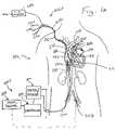
- FIG. 3is a conceptual diagram of a heat exchanger-equipped pulmonary artery catheter device of the present invention operatively positioned for use in a) measuring cardiac output, b) measuring right heart and pulmonary artery pressures and c) heating or cooling the patient's body.
- FIG. 4is a schematic diagram of a basic heat-exchanger equipped catheter of the present invention having sensors for monitoring the temperature of heat exchange fluid flowing into and out of the heat exchanger.
- FIG. 5is a schematic diagram of a basic heat-exchanger equipped catheter of the present invention having temperature sensors for determining the temperature of the patient's blood upstream and downstream of the heat exchange.
- FIGS. 1 and 3show schematic diagrams of a heat exchanger-equipped pulmonary artery catheter device 10 of the present invention that is useable for heating or cooling all or a portion of the patient's body and also for measuring cardiac output without the injection of saline solution or any other foreign substance into the patient's blood.
- this catheter device 10may optionally be equipped and useable for measuring of right heart pressures (e.g., CVP, RVP, PAP, PAP-W), infusing fluids and withdrawing of blood samples (e.g., venous blood samples from a proximal port located in the vena cava or right atrium, mixed venous blood samples from a distal port located in the pulmonary artery).
- this catheter device 10may optionally be equipped to perform other functions such the delivery of electrical current to the heart or to specific locations on the heart muscle for purposes of pacing, defibrillation or diagnostic electrophysiology.
- a catheter device 10comprising an elongate flexible catheter body 12 , a heat exchanger 20 , a balloon 19 , a first or distal temperature sensor 18 (e.g., a thermistor) and a second or proximal temperature sensor 22 (e.g., another thermistor) is positioned as shown, with the heat exchange element 20 in the subclavian vein and perhaps partially within the right atrium, with the distal end DE of the catheter body 12 in the patient's pulmonary artery PA.
- the catheter device 10was placed in this operative position by first percutaneously inserting the distal end DE of the catheter body 12 into the subclavian vein SCV.
- FIG. 1BA particular example is shown in FIG. 1B , wherein the catheter is inserted into the femoral vein. After insertion, the catheter body 12 is advanced first position where the catheter body's distal end DE is positioned in or near the right atrium RA of the patient's heart.
- the balloon 19 located near the catheter body's distal end DEis partially inflated and the pressure of the flowing blood then carries the partially inflated balloon 19 and the distal end of the catheter body through the right atrium RA, through the tricuspid valve TCV, through the right ventricle RV, through the pulmonic valve PV and finally to the second or operative position shown in FIG. 1 , wherein the distal end DE of the catheter body 12 including the balloon 19 and a first temperature sensor (e.g., a thermistor) 18 are situated within the patient's pulmonary artery PA and the heat exchanger 20 is positioned within the superior vena cava SVC adjacent to the right atrium RA.
- a first temperature sensore.g., a thermistor
- the catheter body 12is connected to various extracorporeal apparatus including a heater/cooler 210 for alternately heating and cooling the heat exchanger 20 , a programable controller 220 , and a cardiac output computer apparatus 221 .
- the second or proximal temperature sensor 22is in communication with the controller 220 such that a temperature signal indicative of the blood temperature proximal to or upstream of the heat exchanger 20 is continually monitored or at times determined by the second or proximal temperature sensor 22 .
- the temperature sensor 22may be deployed away from the catheter body 12 by any of several means, for example those shown in co-owned and co-pending U.S. patent application Ser. No. 09/905,389, which is incorporated here by reference.
- the signal or signals from the second or proximal temperature sensor 22is/are communicated by hard wired connection or wireless connection to the controller.
- heat exchange sensor(s)(not shown in FIG. 1 ) which monitor or sense the amount of heat being exchanged between the heat exchanger 20 and the blood flowing past the heat exchanger 20 .
- temperature sensors 39 , 41may be placed on inlet and outlet lines through which heat exchange fluid flows into and out of the heat exchanger 20 .
- the flow rate of heat exchange fluid through the cathetermay also be sensed by a flow meter of any of various kinds (not shown in FIG.
- the rate of heat exchangemay be calculated from the difference between the temperature of the fluid flowing into the heat exchanger and the temperature of the fluid flowing out of the heat exchanger and the rate of flow of the heat exchange fluid. Signals from these sensors 39 , 41 are also communicated to the controller 220 by hard wired or wireless connection and the controller 220 may be programed to compute the amount of heat exchanged during the relevant time period.
- the first or distal temperature sensor 18is also in communication with the controller 220 such that a temperature signal indicative of the blood temperature in the pulmonary artery PA (distal to or downstream of the heat exchanger) may be continually monitored or sampled at various times by the first or distal temperature sensor 18 .
- the signal or signals from the first or distal temperature sensor 18is/are communicated by hard wired connection or wireless connection to the controller 220 .
- the controller 220is additionally programmed to determine the difference between the blood temperature upstream of the heat exchanger 20 as determined by the second temperature sensor 22 and the blood temperature downstream of the heat exchanger (in the pulmonary artery PA) as sensed by the first or distal temperature sensor 18 .
- the catheter device 10may optionally include one or more pressure sensors and/or working lumens and/or ports to facilitate infusion of fluids, withdrawal of blood samples and/or monitoring of local blood pressures at various locations within the right heart.
- FIGS. 1 and 3These aspects of the catheter device 10 shown in FIGS. 1 and 3 are specifically shown in the more detailed views of FIGS. 2–2 c .
- this embodiment of the catheter body 12incorporates multiple optional lumens 28 L, 30 , 32 , 34 , 40 , 42 and 44 L as well as multiple ports 13 , 14 , 16 .
- the lumenscontinue out of a proximal member 34 as separate proximal tubes 37 having Luer connectors or other types of connectors at their proximal ends.
- FIG. 1BAn alternative to having a balloon located on the distal end of the catheter itself as is shown in FIGS. 1 and 1A is illustrated in FIG. 1B .
- a pulmonary artery temperature probewhich may be in the form of a guidewire GW having a temperature sensor 18 b on its distal end DE is advanced into the PA.
- the guidewiremay be flexible and have an inflatable balloon at its distal end for floating placement as described above.
- itmay have a shape that facilitates the location of its distal end in the PA when it is advanced into the heart. That shape may be imparted to the guidewire in numerous ways, for example by using a heat sensitive, shape memory metal such as Nitinol.
- the distal balloonmay be usable to acquire wedge pressures.
- the guidewiremay have at its distal end, in addition to the temperature sensor, a pressure transducer 19 b to determine wedge pressures without the need to insert a balloon into the PA. This may reduce the diameter of the device that needs to be advanced into the PA since no balloon structure needs to be advanced and no lumen needs to be incorporated into the guidewire shaft to inflate the balloon.
- one of the lumens that extends through the catheter body 12 and proximal tubes 37may be a guidewire/pulmonary artery lumen 32 which extends through the catheter body and opens through a distal port 14 in the distal end DE of the catheter body 12 .
- This guidewire/pulmonary artery lumen 32may be initially used to advance the catheter device 10 over a pre-inserted guidewire. Thereafter, after the catheter body 12 has been positioned in its operative position as shown in FIG.
- the guidewiremay be removed and pulmonary artery pressure (PAP) and pulmonary artery wedge pressure (PAP-W) may be monitored though lumen 32 and port 14 by attaching a pressure transducer to the Luer connector on the proximal end of the proximal extension tube 37 of lumen 32 .
- PAPpulmonary artery pressure
- PAP-Wpulmonary artery wedge pressure
- Another lumen 44 Lmay carry a proximal or second temperature sensor wire 44 to connect the proximal or second temperature sensor 18 to the controller 220 and/or cardiac output computer 221 .
- the proximal or second temperaturemay be mounted on a wire or other member 23 which springs or moves outwardly away from the catheter body 12 to hold the temperature sensor 22 sufficiently far away from the catheter body to eliminate or minimize any effect of the heat exchange fluid flowing through the proximal catheter body 12 to or from the heat exchanger, thereby providing a more accurate reading of the blood temperature upstream of the heat exchanger.
- the controller 220may be programmed to apply a correction factor, based on the temperature(s) and flow rates of the heat exchange fluid flowing through the proximal catheter body 12 to or from the heat exchanger, to negate or minimize any effect of such flowing heat exchange fluid on the blood temperature sensed by the proximal or second temperature sensor 13 .
- a balloon inflation/deflation lumen 30extends through the catheter body 12 and through one of the proximal tubes 37 to allow inflation and deflation of the balloon 19 .
- a balloon inflation or pressure indicator(not shown) may be mounted on or integrated into the connector on the proximal end of the extension tube 37 of lumen 30 to indicate the degree to which the balloon 19 is inflated at any given point in time.
- An optional proximal working lumen 34may open through a proximal port 13 which is located within the right atrium RA or adjacent vena cava when the catheter body 12 is in its operative position as shown in FIG. 1 . This proximal working lumen 34 and port 13 may be connected to a pressure transducer and used for monitoring of central venous pressure CVP.
- this proximal working lumen 34 and port 13may be used as a central intravenous line for central administration of drugs, fluids or other substances and/or for withdrawal of non-mixed venous blood samples.
- An optional medial working lumen 26may open through a medial port 16 which is located within the right ventricle RV when the catheter body 12 is in its operative position as shown in FIG. 1 . Such medial working lumen 26 may be used for monitoring of right ventricular pressures or for other access to the right ventricle.
- Heat exchange fluidis pumped into and out of the heat exchanger 20 through heat exchange inflow lumen 40 and heat exchange outflow lumen 42 .
- Temperature sensorsmay be positioned within these lumens 40 , 42 on or adjacent to the Luer connectors at the proximal ends of the extension tubes 37 through which lumens 40 , 42 extend or elsewhere to provide temperature measurements of the heat exchange fluid flowing into and out of the heat exchanger 20 . These temperature measurements may then be used to calculate the amount of heat exchanged between the heat exchanger 20 and the patient's blood, as explained above.
- the heat exchange catheter systemmay be used to simultaneously heat or cool all or a portion of the patient's body to a desired temperature, while determining CO.
- the temperature of the patientis altered by the endovascular heat exchanger 20 , for example the heat exchanger 20 may induce mild hypothermia, the thermal mass of the patient is so large that the change in body temperature is slow enough that it does not significantly impact the determination of CO in accordance with this invention.
- the temperature measured at the first temperature sensor 22would be that of the incoming blood, generally the body temperature
- the temperature measured at the second temperature sensor 18would be the temperature of the blood immediately after the heat exchange, and the relevant measure is the difference of the two temperatures, ⁇ T and thus a change in body temperature would not affect this.
- FIG. 1 aan alternative method and system is shown in FIG. 1 a .
- two (2) separate catheter devicesare used, a heat exchange catheter device 200 a and a pulmonary artery catheter device 202 a .
- the heat exchange catheter device 200 acomprises a heat exchange catheter 204 , a body temperature sensor 207 and related extracorporeal control and operation apparatus 210 , 220 .
- the heat exchange catheter 206has a heat exchanger 206 positioned thereon, and may be any suitable type of heat exchanger including any of those described in U.S. Pat. No.
- the extracorporeal apparatus useable in conjunction with the heat exchange catheter 204include a heater/cooler 210 and controller 220 of as described above with respect to the single catheter embodiment.
- the body temperature sensor 207may be positioned on or in the heat exchange catheter 204 or may be a separate apparatus, such as a small thermistor-equipped catheter that is inserted into a blood vessel other than blood vessel in which the heat exchange catheter 204 is positioned.
- a separate cathetersuch will eliminate any potential for interference with the accurate sensing of blood temperature by the circulation of heated or cooled heat exchange fluid through the proximal portion of the heat exchange catheter.
- the body temperature sensor 207is incorporated into or positioned on the heat exchange catheter 204 it will be positioned proximal to or upstream of the heat exchanger 206 and may be insulated or positioned on a wire or member that deploys the body temperature sensor 207 away from the proximal shaft of the heat exchange catheter 204 , such as the proximal or second temperature sensor 202 described above in connection with the single catheter 10 device.
- the pulmonary artery device 202 acomprises a catheter 208 and an extracorporeal computation apparatus for computing cardiac output.
- the pulmonary artery catheter 208 of this embodimentcomprises an elongate, flexible catheter having a balloon 19 a and pulmonary artery temperature sensor 18 a that are substantially the same as those described above in connection with the single catheter 10 device.
- This pulmonary artery catheter 208may be passed through the right heart and into the pulmonary artery PA by the same flow-directed placement technique described above with respect to the single catheter 10 device.
- this pulmonary artery catheter 208may include other lumens and ports for accessing, infusing fluids into, monitoring pressures (e.g., CVP, RVP, PAP, PAP-W) or withdrawing blood samples (venous, mixed venous), from various locations within the right heart.
- this pulmonary artery cathetermy optionally include a proximal (central venous) lumen and port 34 , 13 , a medial (right ventricular) working lumen and port, 26 , 16 and a distal (pulmonary artery) lumen and port 32 , 14 as described above with respect to the single catheter 10 device.
- the heat exchange catheter system 200 amay be used to simultaneously heat or cool all or a portion of the patient's body to a desired temperature while determining CO. While the heat exchange catheter is exchanging heat with the body, the rate of heat being exchanged between the blood and the heat exchanger may be determined by the same formula and the same technique as described above in connection with the single catheter 10 device.
- the extracorporeal cardiac output computer 218 of this embodimentmay comprise a stand alone device or may be incorporated into or integrated with the controller 220 .
- the heater/coolermay be housed within a common console or housing with the controller and (optionally) the cardiac output computer, thereby providing a unitary extracorporeal system for use during the procedure.
- FIG. 1 bAnother variation of the two-catheter technique is shown in FIG. 1 b .
- a heat exchange catheter 204 as described aboveis inserted into a femoral vein and advanced to a position where its heat exchanger 206 is positioned within the inferior vena cava IVC.
- a lumenextends longitudinally through the heat exchange catheter 204 and may be used to advance the heat exchange catheter 204 over a guidewire.
- the guidewireif used
- a pulmonary artery probe 207is advanced through the central lumen of the heat exchange catheter and out of its distal end.
- the pulmonary artery probe 207may comprise any flexible elongate member such as a catheter, guide wire, wire or the like.
- a balloon 19 b and temperature sensor 18 bare located on the pulmonary artery probe, near its distal end.
- the pulmonary artery probe 207is advanced to a position in or near the right atrium, its balloon 19 b is partially inflated and the flow-directed technique described above is used to float the distal end of the pulmonary artery probe 207 through the right heart and into the patient's pulmonary artery. Thereafter, the temperature sensor 18 b of the pulmonary artery probe 207 may be used to facilitate cardiac output measurements in the same manner as described herein with respect to FIGS. 1 and 1 a .
- the pulmonary artery probe 207may include a lumen that extends through a port distal to the balloon 19 b or a pressure sensor, such as an electronic or fiber optic pressure sensor, distal to the balloon 19 b such that pulmonary artery pressure PAP and pulmonary artery wedge pressure PAP-W may be measured in addition to the ability to measure cardiac output.
- a pressure sensorsuch as an electronic or fiber optic pressure sensor
- the devices and systems of the present inventionare not only useable for determination of cardiac output, but rather are broadly useable for determining blood flow through any blood vessel or the flow rate of any fluid through any body conduit or catheter.
- a heat exchange catheteris placed in the desired blood vessel, conduit or catheter and an upstream temperature T 1 and a downstream temperature T 2 , as shown schematically in Appendix A.
- the amount of heat exchanged between the heat exchanger 20 a and the blood or other flowing fluidis determined as described above with respect to both the single catheter and dual catheter cardiac output determination methods.
- a human patient suffering from a myocardial infarctionis admitted to a critical unit of a hospital.
- a heat exchanger-equipped pulmonary artery catheter 10 of the type described above and shown in FIGS. 1 and 2 – 2 cis percutaneously inserted into the patient's right subclavian vein using a Seidinger technique.
- a guidewiremay be advanced into the patient's superior vena cava and the proximal end of that guidewire is inserted into the distal port 14 of the catheter and through the guidewire/pulmonary artery lumen 32 .
- the catheter body 12is then advanced over the guidewire to a first position where its distal end DE is positioned within or immediately adjacent to the patient's right atrium RA.
- the guidewire, if used,is removed.
- the guidewire/pulmonary artery lumen 32is filled with saline solution or other suitable fluid and the proximal connector of lumen 32 is attached to a physiological pressure transducer (not shown) and the pressure tracing for that transducer is displayed on a monitor (not shown).
- the positioning of the distal port 14 catheter 10 in or adjacent to the right atrium RAis then verifiable by visualization of a typical right atrial waveform on the monitor.
- the balloon 19is then partially inflated to a diameter that is small enough to pass through the tricuspid and pulmonic valves TCV, PV.
- the position of the distal end DE of the catheter in the pulmonary arteryis initially verified by deflation of the balloon 19 and observance of a typical pulmonary artery wave form on the monitor followed by full inflation of the balloon such that it coapts firmly with the wall of the pulmonary artery and observance of a typical pulmonary artery wedge pressure tracing on the monitor. While the catheter body 12 has been positioned in its second or operative position as shown in FIG.
- the heat exchanger 20will be positioned in the superior vena cava SVC
- the proximal port 13(optional) will be positioned in the right atrium RA
- the medial port 16(optional) will be positioned in the right ventricle RV.
- Saline or other suitable fluidmay also be placed in the optional proximal working lumen 34 and central venous pressure (CVP) may be monitored through proximal port 13 such that a tracing of CVP may be displayed on the monitor, if desired.
- CVPcentral venous pressure
- saline or other suitable fluidmay also be placed in the optional medial working lumen 26 and right ventricular pressure (RVP) may be monitored through medial port 16 and a tracing of RVP may be displayed on the monitor.
- Final verification of the proper positioning of the catheter body 12 in the second or operative positionis preferably accomplished by chest x-ray or other suitable radiographic imaging.
- the heat exchanger 20is connected to the heater/cooler 210 .
- the heater/cooler 210 and the proximal thermister 22are in communication with the controller 220 .
- the proximal thermister 22indicates that the patient's body temperature is normothermic at 37° C. In this example, it is desired to cool the patients body to a temperature of approximately 32° C. Thus, the operator inputs the desired 32° C. body temperature into the controller 220 and actuates the system.
- the heater/cooler 210then pumps heated and or cooled saline solution through the heat exchanger 20 , as necessary, to cause the proximal thermister to read approximately 32° C. and the thereafter maintain such desired approximate body temperature.
- This mild hypothermiamay lessen the severity of cardiac muscle damage that occurs as a result of the myocardial infarction. If the patient is awake and alert, one or more anti-shivering treatments or anti-shivering drugs may be administered to prevent or lessen the shivering and discomfort that the patient may experience as a result of the catheter-induced hypothermia.
- the catheter 10may also be used to measure cardiac output.
- the controller 220will receive signals from temperature sensors within the system indicating the temperature of the saline solution being pumped into the heat exchanger (Temp In) and the temperature of the saline solution being returned from the heat exchanger (Temp Out). From this information, the controller then calculates a ⁇ t saline .
- the controller 220also senses the flow rate of the heat exchange fluid (Flow saline ) and uses that flow rate and ⁇ t saline to calculate the rate of heat exchanged between the heat exchanger 20 and the blood (referred to as “Heat Exchanged”). For example, if the Temp In is 4.7° C.
- the controller 220computes Cardiac Output as follows:
- the heat received(or given up) by the bloodwill always be the same as the heat given up (or received) by the heat exchange fluid in any period of time, i.e. power in equals power out, in this case 200 watts. Therefore a determination of cardiac output may be made if the temperature before the heat exchange is measured and the temperature of the mixed blood after the heat exchange is measured. For example, if the temperature before the heat exchange is 36.70 and the temperature after the heat exchange measured (e.g. by a PA temperature sensor) and determined to be 35.66, it would result in a ⁇ t blood of 1.14° C. Using this information and the knowledge that the heat exchange that generated the 1.14° C. is 200 watts, the flow of the blood (i.e. cardiac output) can be determined.
- the patient's cardiac output in this exampleis 2.51 liters/min.
- the constant for the specific heats of two fluidswill remain constant and can be built in to the calculations for CO made by the controller with the assumption that the density and specific heat of the blood and the saline are known.
- the sterile, physiologic salinewill generally not vary. Blood may vary between individuals, at various times in the same individual, and even at different temperatures, but the magnitude of variability will generally be small. Thus, a clinically valuable approximation of cardiac output is obtained even when these variables are ignored.
- the amount of heat exchanged with the bloodcan be determined by measuring the rate of flow of the heat exchange fluid and the difference of the input temperature and the output temperature. If the heat exchange region has been adequately characterized, the velocity of the blood flow can be calculated. If catheters are used that are all similar in heat exchange characteristics, a look-up table can be created wherein the determination of the wattage exchanged with the blood (which may be determined by multiplying the change in temperature of the heat exchange fluid with the flow rate of the heat exchange fluid) then the velocity of blood flowing over the heat exchange region may be derived by looking up the value on a table created using catheters of the type in use.
- This informationby itself may have value to a treating physician. For example it would allow the physician to see if the velocity was within a normal range. It would also be possible, with certain assumptions that are generally accurate, to use that information to determine cardiac output. For example, it would be necessary to know the diameter of the vessel in order to determine the volume of flow at a certain velocity. However, if the height of the patient is known, and the vessel in which the heat exchange region is located is known (for example the IVC) then it would be possible to determine, within a range, what the diameter of that vessel would be and thus determine the amount of blood flow in the IVC. With the additional assumption that the total CO is derived 1 ⁇ 3 from the SVC and 2 ⁇ 3 from the IVC, this would translate very conveniently into CO. While the accuracy would tend to decrease with each additional assumption, it generally would still be accurate enough to be useful.
- the wattage exchanged with the bloodmay be determined by measuring the flow rate of the heat exchange fluid, measuring the temperature of the fluid flowing into the catheter and measuring the temperature of the fluid flowing out of the catheter to determine a ⁇ T, and multiplying the flow rate times the ⁇ T. For example, if the fluid is flowing at the rate of 500 ml/min. and the temperature of the fluid entering the catheter is 5° C. and the temperature of the fluid after exchanging heat with the blood is 10.8° C. and the flow rate of the fluid is 500 ml/min, then the wattage exchanged with the blood is 200 Watts.
- the determination of cardiac output by this methodwill generally be less precise than direct measurement by thermodilution, but for the purposes of monitoring patient condition and making medical treatment decisions, the information may be valuable and helpful even if not precise. Indeed, such information may be clinically useful, even if the blood flow rate measured in the vessel in which the catheter is positioned is different from actual CO. For example, even if the measured flowrate is different from CO, such measured flowrate would nonetheless be expected to vary concurrently with, and in relative magnitude to, changes in CO. Thus, the measured flowrate may indicate whether CO is remaining stable, increasing, decreasing and/or if CO changes so significantly as to indicate a potential problem or “alarm” situation.
- the advantages of determining the information without the need of an additional stick other than the heat exchange catheter and without the need to insert anything into the heart or the PAwill often exceed the disadvantage of slightly less precision.
- One method described hereinprovides the following method for computing the CO if the ⁇ T Blood , the Flow saline and the ⁇ tsaline are determined.
- Power InFlow saline ⁇ T saline
- Flow BloodPower Out/ ⁇ T blood
- CO ⁇ T Blood /0.95Flow saline ⁇ T saline /0.99
- the constant for the specific heat of two fluidswill always be the same and can be built in to the calculations for CO made by the controller with the assumption that the density and specific heat of the blood and the saline are known.
- the sterile, physiologic salinewill generally not vary. Blood may vary between individuals, at various times in the same individual, and even at different temperatures, but the magnitude of variability will generally be small. For purposes of this application we will ignore these variabilities.
Landscapes
- Health & Medical Sciences (AREA)
- Life Sciences & Earth Sciences (AREA)
- Cardiology (AREA)
- Hematology (AREA)
- Heart & Thoracic Surgery (AREA)
- Surgery (AREA)
- Biophysics (AREA)
- Pathology (AREA)
- Engineering & Computer Science (AREA)
- Biomedical Technology (AREA)
- Physiology (AREA)
- Medical Informatics (AREA)
- Molecular Biology (AREA)
- Physics & Mathematics (AREA)
- Animal Behavior & Ethology (AREA)
- General Health & Medical Sciences (AREA)
- Public Health (AREA)
- Veterinary Medicine (AREA)
- Measuring Pulse, Heart Rate, Blood Pressure Or Blood Flow (AREA)
- Measurement Of The Respiration, Hearing Ability, Form, And Blood Characteristics Of Living Organisms (AREA)
- External Artificial Organs (AREA)
Abstract
Description
HR(heartbeats per minute)×SV(liters per heartbeat)=CO(liters per minute)
q=m·(tin−tout)K
wherein q=heat exchange, m=flow rate of heat exchange fluid through the heat exchanger, tin=temperature of heat exchange fluid entering the heat exchanger, tout=temperature of heat exchange fluid exiting the heat exchanger and K=the thermal constant of the heat exchanger fluid.
CO=Heat Exchanged÷Δt
wherein CO=cardiac output (the amount of blood passing through the right heart per unit time), Heat Exchanged=the amount of heat added to or removed from the blood via the
CO=Heat Exchanged÷Δt
wherein CO=cardiac output (the amount of blood passing through the right heart per unit time), Heat Exchanged=the amount of heat added to or removed from the blood via the
Flow Rate=Heat Exchanged÷Δt
wherein the Flow rate is defined as the volume of blood or other fluid flowing past the heat exchanger per unit time, the Heat Exchanged=the amount of heat added to or removed from the blood or fluid via the heat exchanger20aper unit time and Δt=the difference between the upstream temperature T1of the blood or fluid and the downstream temperature T2of the blood or fluid.
- Power=flow rate/ΔT where power is measured in watts, k flow rate is ml/sec. And Δt is degrees Centigrade. In the example above the power is about 200 watts.
CO×ΔTBlood/0.95=Flowsaline×ΔTsaline/0.99
CO=Flowsaline×ΔTsaline×0.95/(0.99×ΔTBlood)
CO=0.5ML/MIN×5.6° C.×0.95/(0.99 ×1.14° C.)=2.35 l/min
| TABLE 1 |
| DATA BASE CORRELATING FLOWRATE OF HEAT EXCHANGE |
| FLUID AND HEAT TRANSFER (WATTS) TO BLOOD FLOW |
| Heat Trans | ||||
(Watts | ||||
| Blood Flow | Catheter Flow | Length) | ||
| 3.6 Lit/min | 500 ml/min | 190.4 | ||
| 3.0 Lit/min | 500 ml/min | 179.8 | ||
| 2.4 Lit/min | 500 ml/min | 156.8 | ||
Power In=Power out
Flowsaline=Power In/ΔTsaline
Power In=Flowsaline×ΔTsaline
FlowBlood=Power Out/ΔTblood
Power In=Power Out
so
CO(which is FlowBlood)×ΔTBlood=Flowsaline×ΔTsaline
CO=ΔTsaline/ΔTBlood×Flowsaline
5.6° C./1.14° C.×0.50 l/min=2.46 l/min
CO=Power×0.95/ΔTBlood; Power=CO×ΔTBlood/0.95
Flowsaline=Power×0.99/ΔTsaline; Power=Flowsaline×ΔTsaline/0.99
CO×ΔTBlood/0.95=Flowsaline×ΔTsaline/0.99
CO=Flowsaline×ΔTsaline×0.95/(0.99×ΔTBlood)
CO=0.5ML/MIN×5.6—C×0.95/(0.99×1.14—C)=2.35 l/min
- 1. Characterize balloon and create look-up table of watts of energy exchanged for a given velocity of blood flow over the catheter.
- 2. Create a look-up table for the typical size of the IVC or other relevant vessel for a given size patient.
- 3. Insert the characterized balloon into the patient.
- 4. Input the patient size.*
- 5. Measure the rate of heat exchange by the characterized heat exchange catheter (e.g. measure the temperature of the heat exchange fluid in and heat exchange fluid out of catheter, or measure the electrical power required to maintain the heat exchange fluid at a given temperature).
- 6. Determine the blood flow velocity from the look-up table.
- 7. Determine the IVC size from the look-up table.*
- 8. Calculate the CO from the blood flow velocity and the IVC size.
- 9. Display the CO. * These steps may be replaced by an actual input value of the size of the IVC or relevant vessel is actually measured, for example by angiography, and the actual value input.
Claims (43)
CO=Heat Exchanged÷Δt
q=m·(tin−tout)K
downstream temperature−upstream temperature.
q=m·(tin−tout)K
Flow Rate per Time Period=Heat Exchanged÷Δt
Flow Rate per Time Period=Heat Exchanged÷Δt
q=m·(tin−tout)K
CO=Heat Exchanged÷Δt
CO=Heat Exchanged÷Δt
q=m·(tin−tout)K
downstream temperature−upstream temperature.
Priority Applications (1)
| Application Number | Priority Date | Filing Date | Title |
|---|---|---|---|
| US10/394,505US7087026B2 (en) | 2002-03-21 | 2003-03-21 | Devices and methods for measuring blood flow rate or cardiac output and for heating or cooling the body |
Applications Claiming Priority (2)
| Application Number | Priority Date | Filing Date | Title |
|---|---|---|---|
| US36628202P | 2002-03-21 | 2002-03-21 | |
| US10/394,505US7087026B2 (en) | 2002-03-21 | 2003-03-21 | Devices and methods for measuring blood flow rate or cardiac output and for heating or cooling the body |
Publications (2)
| Publication Number | Publication Date |
|---|---|
| US20030225336A1 US20030225336A1 (en) | 2003-12-04 |
| US7087026B2true US7087026B2 (en) | 2006-08-08 |
Family
ID=28454773
Family Applications (1)
| Application Number | Title | Priority Date | Filing Date |
|---|---|---|---|
| US10/394,505Expired - LifetimeUS7087026B2 (en) | 2002-03-21 | 2003-03-21 | Devices and methods for measuring blood flow rate or cardiac output and for heating or cooling the body |
Country Status (3)
| Country | Link |
|---|---|
| US (1) | US7087026B2 (en) |
| AU (1) | AU2003220474A1 (en) |
| WO (1) | WO2003079887A2 (en) |
Cited By (107)
| Publication number | Priority date | Publication date | Assignee | Title |
|---|---|---|---|---|
| US20040181158A1 (en)* | 1993-08-13 | 2004-09-16 | Bowman Harry Frederick | Blood flow monitor with venous and arterial sensors |
| US20040249265A1 (en)* | 2003-03-31 | 2004-12-09 | Friedrich Fuchs | Method and apparatus for examining blood vessel responsiveness |
| US20060100595A1 (en)* | 2004-11-09 | 2006-05-11 | Von Dyck Peter M | Bowel management system with physiologic sensors |
| US20070167861A1 (en)* | 2005-11-29 | 2007-07-19 | Lopez George A | Cardiac output measurement devices and methods |
| US20080228063A1 (en)* | 2005-11-22 | 2008-09-18 | Bsd Medical Corporation | System and method for irradiating a target with electromagnetic radiation to produce a heated region |
| WO2010042667A3 (en)* | 2008-10-07 | 2010-06-03 | Xcorporeal, Inc. | Thermal flow meter |
| US8597505B2 (en) | 2007-09-13 | 2013-12-03 | Fresenius Medical Care Holdings, Inc. | Portable dialysis machine |
| US8771511B2 (en) | 2007-11-29 | 2014-07-08 | Fresenius Medical Care Holdings, Inc. | Disposable apparatus and kit for conducting dialysis |
| US8880185B2 (en) | 2010-06-11 | 2014-11-04 | Boston Scientific Scimed, Inc. | Renal denervation and stimulation employing wireless vascular energy transfer arrangement |
| US8939970B2 (en) | 2004-09-10 | 2015-01-27 | Vessix Vascular, Inc. | Tuned RF energy and electrical tissue characterization for selective treatment of target tissues |
| US8951251B2 (en) | 2011-11-08 | 2015-02-10 | Boston Scientific Scimed, Inc. | Ostial renal nerve ablation |
| US8974451B2 (en) | 2010-10-25 | 2015-03-10 | Boston Scientific Scimed, Inc. | Renal nerve ablation using conductive fluid jet and RF energy |
| US9023034B2 (en) | 2010-11-22 | 2015-05-05 | Boston Scientific Scimed, Inc. | Renal ablation electrode with force-activatable conduction apparatus |
| US9028485B2 (en) | 2010-11-15 | 2015-05-12 | Boston Scientific Scimed, Inc. | Self-expanding cooling electrode for renal nerve ablation |
| US9028472B2 (en) | 2011-12-23 | 2015-05-12 | Vessix Vascular, Inc. | Methods and apparatuses for remodeling tissue of or adjacent to a body passage |
| US9050106B2 (en) | 2011-12-29 | 2015-06-09 | Boston Scientific Scimed, Inc. | Off-wall electrode device and methods for nerve modulation |
| US9060761B2 (en) | 2010-11-18 | 2015-06-23 | Boston Scientific Scime, Inc. | Catheter-focused magnetic field induced renal nerve ablation |
| US9079000B2 (en) | 2011-10-18 | 2015-07-14 | Boston Scientific Scimed, Inc. | Integrated crossing balloon catheter |
| US9084609B2 (en) | 2010-07-30 | 2015-07-21 | Boston Scientific Scime, Inc. | Spiral balloon catheter for renal nerve ablation |
| US9089350B2 (en) | 2010-11-16 | 2015-07-28 | Boston Scientific Scimed, Inc. | Renal denervation catheter with RF electrode and integral contrast dye injection arrangement |
| US9119600B2 (en) | 2011-11-15 | 2015-09-01 | Boston Scientific Scimed, Inc. | Device and methods for renal nerve modulation monitoring |
| US9119632B2 (en) | 2011-11-21 | 2015-09-01 | Boston Scientific Scimed, Inc. | Deflectable renal nerve ablation catheter |
| US9125666B2 (en) | 2003-09-12 | 2015-09-08 | Vessix Vascular, Inc. | Selectable eccentric remodeling and/or ablation of atherosclerotic material |
| US9125667B2 (en) | 2004-09-10 | 2015-09-08 | Vessix Vascular, Inc. | System for inducing desirable temperature effects on body tissue |
| US20150272513A1 (en)* | 2014-03-07 | 2015-10-01 | Zoll Circulation, Inc. | Endovascular Heat Exchange Systems and Methods with Blood Flow Monitoring and Notification Functions |
| US9155589B2 (en) | 2010-07-30 | 2015-10-13 | Boston Scientific Scimed, Inc. | Sequential activation RF electrode set for renal nerve ablation |
| US9157786B2 (en) | 2012-12-24 | 2015-10-13 | Fresenius Medical Care Holdings, Inc. | Load suspension and weighing system for a dialysis machine reservoir |
| US9162046B2 (en) | 2011-10-18 | 2015-10-20 | Boston Scientific Scimed, Inc. | Deflectable medical devices |
| US9173696B2 (en) | 2012-09-17 | 2015-11-03 | Boston Scientific Scimed, Inc. | Self-positioning electrode system and method for renal nerve modulation |
| US9186210B2 (en) | 2011-10-10 | 2015-11-17 | Boston Scientific Scimed, Inc. | Medical devices including ablation electrodes |
| US9186209B2 (en) | 2011-07-22 | 2015-11-17 | Boston Scientific Scimed, Inc. | Nerve modulation system having helical guide |
| US9192435B2 (en) | 2010-11-22 | 2015-11-24 | Boston Scientific Scimed, Inc. | Renal denervation catheter with cooled RF electrode |
| US9192790B2 (en) | 2010-04-14 | 2015-11-24 | Boston Scientific Scimed, Inc. | Focused ultrasonic renal denervation |
| US9199022B2 (en) | 2008-09-12 | 2015-12-01 | Fresenius Medical Care Holdings, Inc. | Modular reservoir assembly for a hemodialysis and hemofiltration system |
| US9220558B2 (en) | 2010-10-27 | 2015-12-29 | Boston Scientific Scimed, Inc. | RF renal denervation catheter with multiple independent electrodes |
| US9220561B2 (en) | 2011-01-19 | 2015-12-29 | Boston Scientific Scimed, Inc. | Guide-compatible large-electrode catheter for renal nerve ablation with reduced arterial injury |
| US9265969B2 (en) | 2011-12-21 | 2016-02-23 | Cardiac Pacemakers, Inc. | Methods for modulating cell function |
| US9277955B2 (en) | 2010-04-09 | 2016-03-08 | Vessix Vascular, Inc. | Power generating and control apparatus for the treatment of tissue |
| US9295772B2 (en) | 2007-11-29 | 2016-03-29 | Fresenius Medical Care Holdings, Inc. | Priming system and method for dialysis systems |
| US9297845B2 (en) | 2013-03-15 | 2016-03-29 | Boston Scientific Scimed, Inc. | Medical devices and methods for treatment of hypertension that utilize impedance compensation |
| US9308307B2 (en) | 2007-09-13 | 2016-04-12 | Fresenius Medical Care Holdings, Inc. | Manifold diaphragms |
| US9327100B2 (en) | 2008-11-14 | 2016-05-03 | Vessix Vascular, Inc. | Selective drug delivery in a lumen |
| US9326751B2 (en) | 2010-11-17 | 2016-05-03 | Boston Scientific Scimed, Inc. | Catheter guidance of external energy for renal denervation |
| US9354640B2 (en) | 2013-11-11 | 2016-05-31 | Fresenius Medical Care Holdings, Inc. | Smart actuator for valve |
| US9352282B2 (en) | 2007-09-25 | 2016-05-31 | Fresenius Medical Care Holdings, Inc. | Manifolds for use in conducting dialysis |
| US9358331B2 (en) | 2007-09-13 | 2016-06-07 | Fresenius Medical Care Holdings, Inc. | Portable dialysis machine with improved reservoir heating system |
| US9360129B2 (en) | 2009-01-12 | 2016-06-07 | Fresenius Medical Care Holdings, Inc. | Valve system |
| US9358365B2 (en) | 2010-07-30 | 2016-06-07 | Boston Scientific Scimed, Inc. | Precision electrode movement control for renal nerve ablation |
| US9364284B2 (en) | 2011-10-12 | 2016-06-14 | Boston Scientific Scimed, Inc. | Method of making an off-wall spacer cage |
| US9408661B2 (en) | 2010-07-30 | 2016-08-09 | Patrick A. Haverkost | RF electrodes on multiple flexible wires for renal nerve ablation |
| US9420955B2 (en) | 2011-10-11 | 2016-08-23 | Boston Scientific Scimed, Inc. | Intravascular temperature monitoring system and method |
| US9433760B2 (en) | 2011-12-28 | 2016-09-06 | Boston Scientific Scimed, Inc. | Device and methods for nerve modulation using a novel ablation catheter with polymeric ablative elements |
| US9463062B2 (en) | 2010-07-30 | 2016-10-11 | Boston Scientific Scimed, Inc. | Cooled conductive balloon RF catheter for renal nerve ablation |
| US9486355B2 (en) | 2005-05-03 | 2016-11-08 | Vessix Vascular, Inc. | Selective accumulation of energy with or without knowledge of tissue topography |
| US9579030B2 (en) | 2011-07-20 | 2017-02-28 | Boston Scientific Scimed, Inc. | Percutaneous devices and methods to visualize, target and ablate nerves |
| US9649156B2 (en) | 2010-12-15 | 2017-05-16 | Boston Scientific Scimed, Inc. | Bipolar off-wall electrode device for renal nerve ablation |
| US9668811B2 (en) | 2010-11-16 | 2017-06-06 | Boston Scientific Scimed, Inc. | Minimally invasive access for renal nerve ablation |
| US9687166B2 (en) | 2013-10-14 | 2017-06-27 | Boston Scientific Scimed, Inc. | High resolution cardiac mapping electrode array catheter |
| US9693821B2 (en) | 2013-03-11 | 2017-07-04 | Boston Scientific Scimed, Inc. | Medical devices for modulating nerves |
| US9707036B2 (en) | 2013-06-25 | 2017-07-18 | Boston Scientific Scimed, Inc. | Devices and methods for nerve modulation using localized indifferent electrodes |
| US9713730B2 (en) | 2004-09-10 | 2017-07-25 | Boston Scientific Scimed, Inc. | Apparatus and method for treatment of in-stent restenosis |
| US9757193B2 (en) | 2002-04-08 | 2017-09-12 | Medtronic Ardian Luxembourg S.A.R.L. | Balloon catheter apparatus for renal neuromodulation |
| US9770606B2 (en) | 2013-10-15 | 2017-09-26 | Boston Scientific Scimed, Inc. | Ultrasound ablation catheter with cooling infusion and centering basket |
| US9808300B2 (en) | 2006-05-02 | 2017-11-07 | Boston Scientific Scimed, Inc. | Control of arterial smooth muscle tone |
| US9808311B2 (en) | 2013-03-13 | 2017-11-07 | Boston Scientific Scimed, Inc. | Deflectable medical devices |
| US9827040B2 (en) | 2002-04-08 | 2017-11-28 | Medtronic Adrian Luxembourg S.a.r.l. | Methods and apparatus for intravascularly-induced neuromodulation |
| US9827039B2 (en) | 2013-03-15 | 2017-11-28 | Boston Scientific Scimed, Inc. | Methods and apparatuses for remodeling tissue of or adjacent to a body passage |
| US9833283B2 (en) | 2013-07-01 | 2017-12-05 | Boston Scientific Scimed, Inc. | Medical devices for renal nerve ablation |
| US9895194B2 (en) | 2013-09-04 | 2018-02-20 | Boston Scientific Scimed, Inc. | Radio frequency (RF) balloon catheter having flushing and cooling capability |
| US9907609B2 (en) | 2014-02-04 | 2018-03-06 | Boston Scientific Scimed, Inc. | Alternative placement of thermal sensors on bipolar electrode |
| US9919144B2 (en) | 2011-04-08 | 2018-03-20 | Medtronic Adrian Luxembourg S.a.r.l. | Iontophoresis drug delivery system and method for denervation of the renal sympathetic nerve and iontophoretic drug delivery |
| US9925001B2 (en) | 2013-07-19 | 2018-03-27 | Boston Scientific Scimed, Inc. | Spiral bipolar electrode renal denervation balloon |
| US9943365B2 (en) | 2013-06-21 | 2018-04-17 | Boston Scientific Scimed, Inc. | Renal denervation balloon catheter with ride along electrode support |
| US9956033B2 (en) | 2013-03-11 | 2018-05-01 | Boston Scientific Scimed, Inc. | Medical devices for modulating nerves |
| US9962223B2 (en) | 2013-10-15 | 2018-05-08 | Boston Scientific Scimed, Inc. | Medical device balloon |
| US9974607B2 (en) | 2006-10-18 | 2018-05-22 | Vessix Vascular, Inc. | Inducing desirable temperature effects on body tissue |
| US10022182B2 (en) | 2013-06-21 | 2018-07-17 | Boston Scientific Scimed, Inc. | Medical devices for renal nerve ablation having rotatable shafts |
| US10035103B2 (en) | 2008-10-30 | 2018-07-31 | Fresenius Medical Care Holdings, Inc. | Modular, portable dialysis system |
| US10085799B2 (en) | 2011-10-11 | 2018-10-02 | Boston Scientific Scimed, Inc. | Off-wall electrode device and methods for nerve modulation |
| US10195326B2 (en) | 2016-03-08 | 2019-02-05 | Fresenius Medical Care Holdings, Inc. | Methods and systems for detecting an occlusion in a blood circuit of a dialysis system |
| US10265122B2 (en) | 2013-03-15 | 2019-04-23 | Boston Scientific Scimed, Inc. | Nerve ablation devices and related methods of use |
| US10271898B2 (en) | 2013-10-25 | 2019-04-30 | Boston Scientific Scimed, Inc. | Embedded thermocouple in denervation flex circuit |
| US10321946B2 (en) | 2012-08-24 | 2019-06-18 | Boston Scientific Scimed, Inc. | Renal nerve modulation devices with weeping RF ablation balloons |
| US10342609B2 (en) | 2013-07-22 | 2019-07-09 | Boston Scientific Scimed, Inc. | Medical devices for renal nerve ablation |
| US10398464B2 (en) | 2012-09-21 | 2019-09-03 | Boston Scientific Scimed, Inc. | System for nerve modulation and innocuous thermal gradient nerve block |
| US10413357B2 (en) | 2013-07-11 | 2019-09-17 | Boston Scientific Scimed, Inc. | Medical device with stretchable electrode assemblies |
| US10549127B2 (en) | 2012-09-21 | 2020-02-04 | Boston Scientific Scimed, Inc. | Self-cooling ultrasound ablation catheter |
| US10561778B2 (en) | 2017-03-02 | 2020-02-18 | Fresenius Medical Care Holdings, Inc. | Split reservoir bags and method of using split reservoir bags to improve the heating and generation of dialysate |
| US10588682B2 (en) | 2011-04-25 | 2020-03-17 | Medtronic Ardian Luxembourg S.A.R.L. | Apparatus and methods related to constrained deployment of cryogenic balloons for limited cryogenic ablation of vessel walls |
| US10660703B2 (en) | 2012-05-08 | 2020-05-26 | Boston Scientific Scimed, Inc. | Renal nerve modulation devices |
| US10660698B2 (en) | 2013-07-11 | 2020-05-26 | Boston Scientific Scimed, Inc. | Devices and methods for nerve modulation |
| US10695124B2 (en) | 2013-07-22 | 2020-06-30 | Boston Scientific Scimed, Inc. | Renal nerve ablation catheter having twist balloon |
| US10709490B2 (en) | 2014-05-07 | 2020-07-14 | Medtronic Ardian Luxembourg S.A.R.L. | Catheter assemblies comprising a direct heating element for renal neuromodulation and associated systems and methods |
| US10722300B2 (en) | 2013-08-22 | 2020-07-28 | Boston Scientific Scimed, Inc. | Flexible circuit having improved adhesion to a renal nerve modulation balloon |
| US10786616B2 (en) | 2015-12-17 | 2020-09-29 | Fresnius Medical Care Holdings, Inc. | System and method for controlling venous air recovery in a portable dialysis system |
| US10835305B2 (en) | 2012-10-10 | 2020-11-17 | Boston Scientific Scimed, Inc. | Renal nerve modulation devices and methods |
| US10945786B2 (en) | 2013-10-18 | 2021-03-16 | Boston Scientific Scimed, Inc. | Balloon catheters with flexible conducting wires and related methods of use and manufacture |
| US10952790B2 (en) | 2013-09-13 | 2021-03-23 | Boston Scientific Scimed, Inc. | Ablation balloon with vapor deposited cover layer |
| US10987460B2 (en) | 2016-03-08 | 2021-04-27 | Fresenius Medical Care Holdings, Inc. | Methods and systems of generating rapidly varying pressure amplitudes in fluidic circuits in a dialysis treatment system |
| US11000679B2 (en) | 2014-02-04 | 2021-05-11 | Boston Scientific Scimed, Inc. | Balloon protection and rewrapping devices and related methods of use |
| US11013554B2 (en) | 2014-11-14 | 2021-05-25 | Medtronic Ardian Lexembourg S.A.R.L. | Catheter apparatuses for modulation of nerves in communication with pulmonary system and associated systems and methods |
| US11110214B2 (en) | 2017-04-07 | 2021-09-07 | Fresenius Medical Care Holdings, Inc. | Methods and systems for measuring and heating dialysate |
| US11202671B2 (en) | 2014-01-06 | 2021-12-21 | Boston Scientific Scimed, Inc. | Tear resistant flex circuit assembly |
| US11246654B2 (en) | 2013-10-14 | 2022-02-15 | Boston Scientific Scimed, Inc. | Flexible renal nerve ablation devices and related methods of use and manufacture |
| US11497648B2 (en)* | 2017-05-12 | 2022-11-15 | Zoll Circulation, Inc. | Advanced systems and methods for patient body temperature control |
| US11525798B2 (en) | 2012-12-21 | 2022-12-13 | Fresenius Medical Care Holdings, Inc. | Method and system of monitoring electrolyte levels and composition using capacitance or induction |
| US11992433B2 (en) | 2017-05-12 | 2024-05-28 | Zoll Circulation, Inc. | Advanced systems and methods for patient body temperature control |
Families Citing this family (48)
| Publication number | Priority date | Publication date | Assignee | Title |
|---|---|---|---|---|
| US8128595B2 (en) | 1998-04-21 | 2012-03-06 | Zoll Circulation, Inc. | Method for a central venous line catheter having a temperature control system |
| US6338727B1 (en) | 1998-08-13 | 2002-01-15 | Alsius Corporation | Indwelling heat exchange catheter and method of using same |
| US7179279B2 (en) | 2002-09-30 | 2007-02-20 | Medtronic Physio Control Corp. | Rapid induction of mild hypothermia |
| US7087075B2 (en) | 2002-09-30 | 2006-08-08 | Medtronic Emergency Response Systems, Inc. | Feedback system for rapid induction of mild hypothermia |
| US7056282B2 (en) | 2002-12-23 | 2006-06-06 | Medtronic Emergency Response Systems, Inc. | Coolant control for rapid induction of mild hypothermia |
| US7947030B2 (en)* | 2004-12-30 | 2011-05-24 | Reynaldo Calderon | Retrograde perfusion of tumor sites |
| US7425216B2 (en) | 2005-03-01 | 2008-09-16 | Alsius Corporation | System and method for treating cardiac arrest and myocardial infarction |
| US7892269B2 (en) | 2005-04-18 | 2011-02-22 | Zoll Circulation, Inc. | External heat exchange pad for patient |
| US7181927B2 (en) | 2005-07-01 | 2007-02-27 | Alsius Corporation | Primary heat exchanger for patient temperature control |
| US7951182B2 (en) | 2005-07-14 | 2011-05-31 | Zoll Circulation, Inc. | System and method for leak detection in external cooling pad |
| US7563231B2 (en)* | 2006-02-15 | 2009-07-21 | Medtronic, Inc. | Rapid thermal detection of cardiac output change |
| US7643879B2 (en) | 2006-08-24 | 2010-01-05 | Cardiac Pacemakers, Inc. | Integrated cardiac rhythm management system with heart valve |
| US7822485B2 (en) | 2006-09-25 | 2010-10-26 | Zoll Circulation, Inc. | Method and apparatus for spinal cooling |
| US7867266B2 (en) | 2006-11-13 | 2011-01-11 | Zoll Circulation, Inc. | Temperature management system with assist mode for use with heart-lung machine |
| US8353893B2 (en) | 2007-03-07 | 2013-01-15 | Zoll Circulation, Inc. | System and method for rapidly cooling cardiac arrest patient |
| US9737692B2 (en) | 2007-05-18 | 2017-08-22 | Zoll Circulation, Inc. | System and method for effecting non-standard fluid line connections |
| EP2062528B1 (en)* | 2007-11-23 | 2012-03-14 | Pulsion Medical Systems AG | Central venous sensor assembly for measuring physiological data for cardiac output determination and method of determining cardiac output |
| US8197413B2 (en) | 2008-06-06 | 2012-06-12 | Boston Scientific Scimed, Inc. | Transducers, devices and systems containing the transducers, and methods of manufacture |
| GB2476751B (en)* | 2008-10-08 | 2013-08-07 | Bedrock Inv S Llc | Measuring shivering during therapeutic temperature control |
| US9554742B2 (en) | 2009-07-20 | 2017-01-31 | Optiscan Biomedical Corporation | Fluid analysis system |
| EP2456355B1 (en) | 2009-07-20 | 2016-09-14 | Optiscan Biomedical Corporation | Adjustable connector and dead space reduction |
| WO2011159956A1 (en)* | 2010-06-17 | 2011-12-22 | Optiscan Biomedical Corporation | Systems and methods to reduce fluid contamination |
| SG193365A1 (en)* | 2011-03-09 | 2013-10-30 | Nanyang Polytechnic | A blood flow rate measurement system |
| US9259348B2 (en)* | 2011-09-28 | 2016-02-16 | Zoll Circulation, Inc. | Transatrial patient temperature control catheter |
| CN104739400B (en)* | 2013-12-31 | 2020-09-15 | 深圳迈瑞生物医疗电子股份有限公司 | Automatic cardiac output measuring system |
| WO2015160943A1 (en)* | 2014-04-15 | 2015-10-22 | Thoratec Corporation | Sensors for catheter pumps |
| WO2016007288A1 (en)* | 2014-07-08 | 2016-01-14 | Nadarasa Visveshwara | System and method for measuring fluidics in arteries |
| US9320493B2 (en) | 2014-07-08 | 2016-04-26 | Nadarasa Visveshwara | System and method for measuring fluidics in arteries |
| US10736604B2 (en)* | 2016-01-14 | 2020-08-11 | University Of Maryland, Baltimore | System and method for assessment of cardiac stroke volume and volume responsiveness |
| WO2017147493A1 (en) | 2016-02-24 | 2017-08-31 | Incept, Llc | Enhanced flexibility neurovascular catheter |
| CN109310338B (en) | 2016-06-29 | 2021-11-19 | 皮科洛医疗公司 | Device and method for vessel navigation, evaluation and/or diagnosis |
| WO2018060064A1 (en)* | 2016-09-28 | 2018-04-05 | Koninklijke Philips N.V. | System for determining blood flow |
| JP7264581B2 (en) | 2017-01-06 | 2023-04-25 | インセプト、リミテッド、ライアビリティ、カンパニー | Antithrombotic coating for aneurysm treatment devices |
| US11395665B2 (en) | 2018-05-01 | 2022-07-26 | Incept, Llc | Devices and methods for removing obstructive material, from an intravascular site |
| AU2019262972B2 (en) | 2018-05-01 | 2025-02-27 | Incept, Llc | Devices and methods for removing obstructive material from an intravascular site |
| US11517335B2 (en) | 2018-07-06 | 2022-12-06 | Incept, Llc | Sealed neurovascular extendable catheter |
| US11471582B2 (en) | 2018-07-06 | 2022-10-18 | Incept, Llc | Vacuum transfer tool for extendable catheter |
| US11766539B2 (en) | 2019-03-29 | 2023-09-26 | Incept, Llc | Enhanced flexibility neurovascular catheter |
| US11134859B2 (en) | 2019-10-15 | 2021-10-05 | Imperative Care, Inc. | Systems and methods for multivariate stroke detection |
| EP4076611A4 (en) | 2019-12-18 | 2023-11-15 | Imperative Care, Inc. | Methods and systems for treating venous thromboembolic disease |
| US20230248502A1 (en) | 2019-12-18 | 2023-08-10 | Imperative Care, Inc. | Sterile field clot capture module for use in thrombectomy system |
| US20210316127A1 (en) | 2019-12-18 | 2021-10-14 | Imperative Care, Inc. | Hemostasis valve |
| US11638637B2 (en) | 2019-12-18 | 2023-05-02 | Imperative Care, Inc. | Method of removing embolic material with thrombus engagement tool |
| CN113747934B (en) | 2020-03-10 | 2024-07-09 | 因普瑞缇夫护理公司 | Enhanced flexibility neurovascular catheter |
| US11207497B1 (en) | 2020-08-11 | 2021-12-28 | Imperative Care, Inc. | Catheter with enhanced tensile strength |
| US20230052862A1 (en) | 2021-08-12 | 2023-02-16 | Imperative Care, Inc. | Sterile packaging assembly for robotic interventional device |
| USD1077996S1 (en) | 2021-10-18 | 2025-06-03 | Imperative Care, Inc. | Inline fluid filter |
| US12171917B1 (en) | 2024-01-08 | 2024-12-24 | Imperative Care, Inc. | Devices for blood capture and reintroduction during aspiration procedure |
Citations (18)
| Publication number | Priority date | Publication date | Assignee | Title |
|---|---|---|---|---|
| US4819655A (en)* | 1987-08-04 | 1989-04-11 | Webler William E | Injectateless thermal cardiac output determination method and apparatus |
| US4941475A (en)* | 1988-08-30 | 1990-07-17 | Spectramed, Inc. | Thermodilution by heat exchange |
| WO1991017703A1 (en)* | 1990-05-19 | 1991-11-28 | Cpec Corporation | Apparatus and method for monitoring cardiac output |
| US5217019A (en) | 1991-12-27 | 1993-06-08 | Abbott Laboratories | Apparatus and method for continuously monitoring cardiac output |
| US5271410A (en) | 1991-04-01 | 1993-12-21 | Baxter International Inc. | Catheter with rapid response thermistor and method |
| US5509424A (en)* | 1994-01-28 | 1996-04-23 | Aws Salim Nashef | Continuous cardiac output monitoring system |
| US5579778A (en)* | 1993-09-09 | 1996-12-03 | University Of Utah Research Foundation | Method and apparatus for producing thermodilution cardiac output measurements utilizing a neural network |
| US5588438A (en) | 1991-01-29 | 1996-12-31 | Interflo Medical, Inc. | System and method for controlling the temperature of a catheter-mounted heater |
| US5682899A (en)* | 1991-05-16 | 1997-11-04 | Ami-Med Corporation | Apparatus and method for continuous cardiac output monitoring |
| US5692514A (en)* | 1993-08-13 | 1997-12-02 | Thermal Technologies, Inc. | Method and apparatus for measuring continuous blood flow at low power |
| US5788647A (en) | 1997-01-24 | 1998-08-04 | Eggers; Philip E. | Method, system and apparatus for evaluating hemodynamic parameters |
| US5807269A (en) | 1991-01-29 | 1998-09-15 | Baxter International Inc. | Thermodilution catheter having a safe, flexible heating element |
| US5837003A (en) | 1993-02-10 | 1998-11-17 | Radiant Medical, Inc. | Method and apparatus for controlling a patient's body temperature by in situ blood temperature modification |
| US5954659A (en)* | 1996-02-16 | 1999-09-21 | Curley; Michael G. | Method and apparatus for invasively measuring cardiac output by detecting temperature differences of blood heated by radiation |
| WO2001058397A1 (en) | 2000-02-09 | 2001-08-16 | Radiant Medical, Inc. | Multiple lumen heat exchange catheters |
| US6394961B1 (en) | 1999-10-28 | 2002-05-28 | Pulsion Medical Systems Ag | Method to increase transpulmonary thermodilution cardiac output accuracy by use of extravascular thermovolume to control the amount of thermal indicator |
| US6416533B1 (en) | 1998-04-21 | 2002-07-09 | Alsius Corporation | Indwelling heat exchange catheter and method of using same |
| US6497721B2 (en) | 1993-02-10 | 2002-12-24 | Radiant Medical, Inc. | Method and apparatus for regional and whole body temperature modification |
Family Cites Families (1)
| Publication number | Priority date | Publication date | Assignee | Title |
|---|---|---|---|---|
| JPS63258230A (en)* | 1987-04-15 | 1988-10-25 | Mitsubishi Electric Corp | Constant speed driving control device for vehicles |
- 2003
- 2003-03-21AUAU2003220474Apatent/AU2003220474A1/ennot_activeAbandoned
- 2003-03-21USUS10/394,505patent/US7087026B2/ennot_activeExpired - Lifetime
- 2003-03-21WOPCT/US2003/008862patent/WO2003079887A2/ennot_activeApplication Discontinuation
Patent Citations (19)
| Publication number | Priority date | Publication date | Assignee | Title |
|---|---|---|---|---|
| US4819655A (en)* | 1987-08-04 | 1989-04-11 | Webler William E | Injectateless thermal cardiac output determination method and apparatus |
| US4941475A (en)* | 1988-08-30 | 1990-07-17 | Spectramed, Inc. | Thermodilution by heat exchange |
| WO1991017703A1 (en)* | 1990-05-19 | 1991-11-28 | Cpec Corporation | Apparatus and method for monitoring cardiac output |
| US5807269A (en) | 1991-01-29 | 1998-09-15 | Baxter International Inc. | Thermodilution catheter having a safe, flexible heating element |
| US5588438A (en) | 1991-01-29 | 1996-12-31 | Interflo Medical, Inc. | System and method for controlling the temperature of a catheter-mounted heater |
| US5271410A (en) | 1991-04-01 | 1993-12-21 | Baxter International Inc. | Catheter with rapid response thermistor and method |
| US5682899A (en)* | 1991-05-16 | 1997-11-04 | Ami-Med Corporation | Apparatus and method for continuous cardiac output monitoring |
| US5217019A (en) | 1991-12-27 | 1993-06-08 | Abbott Laboratories | Apparatus and method for continuously monitoring cardiac output |
| US5285796A (en)* | 1991-12-27 | 1994-02-15 | Abbott Laboratories | Method for continuously monitoring cardiac output |
| US6497721B2 (en) | 1993-02-10 | 2002-12-24 | Radiant Medical, Inc. | Method and apparatus for regional and whole body temperature modification |
| US5837003A (en) | 1993-02-10 | 1998-11-17 | Radiant Medical, Inc. | Method and apparatus for controlling a patient's body temperature by in situ blood temperature modification |
| US5692514A (en)* | 1993-08-13 | 1997-12-02 | Thermal Technologies, Inc. | Method and apparatus for measuring continuous blood flow at low power |
| US5579778A (en)* | 1993-09-09 | 1996-12-03 | University Of Utah Research Foundation | Method and apparatus for producing thermodilution cardiac output measurements utilizing a neural network |
| US5509424A (en)* | 1994-01-28 | 1996-04-23 | Aws Salim Nashef | Continuous cardiac output monitoring system |
| US5954659A (en)* | 1996-02-16 | 1999-09-21 | Curley; Michael G. | Method and apparatus for invasively measuring cardiac output by detecting temperature differences of blood heated by radiation |
| US5788647A (en) | 1997-01-24 | 1998-08-04 | Eggers; Philip E. | Method, system and apparatus for evaluating hemodynamic parameters |
| US6416533B1 (en) | 1998-04-21 | 2002-07-09 | Alsius Corporation | Indwelling heat exchange catheter and method of using same |
| US6394961B1 (en) | 1999-10-28 | 2002-05-28 | Pulsion Medical Systems Ag | Method to increase transpulmonary thermodilution cardiac output accuracy by use of extravascular thermovolume to control the amount of thermal indicator |
| WO2001058397A1 (en) | 2000-02-09 | 2001-08-16 | Radiant Medical, Inc. | Multiple lumen heat exchange catheters |
Cited By (159)
| Publication number | Priority date | Publication date | Assignee | Title |
|---|---|---|---|---|
| US20080039732A9 (en)* | 1993-08-13 | 2008-02-14 | Bowman Harry F | Blood flow monitor with venous and arterial sensors |
| US7527598B2 (en)* | 1993-08-13 | 2009-05-05 | Thermal Technologies, Inc. | Blood flow monitor with venous and arterial sensors |
| US20040181158A1 (en)* | 1993-08-13 | 2004-09-16 | Bowman Harry Frederick | Blood flow monitor with venous and arterial sensors |
| US10376311B2 (en) | 2002-04-08 | 2019-08-13 | Medtronic Ardian Luxembourg S.A.R.L. | Methods and apparatus for intravascularly-induced neuromodulation |
| US10420606B2 (en) | 2002-04-08 | 2019-09-24 | Medtronic Ardian Luxembourg S.A.R.L. | Methods and apparatus for performing a non-continuous circumferential treatment of a body lumen |
| US9827041B2 (en) | 2002-04-08 | 2017-11-28 | Medtronic Ardian Luxembourg S.A.R.L. | Balloon catheter apparatuses for renal denervation |
| US9827040B2 (en) | 2002-04-08 | 2017-11-28 | Medtronic Adrian Luxembourg S.a.r.l. | Methods and apparatus for intravascularly-induced neuromodulation |
| US10105180B2 (en) | 2002-04-08 | 2018-10-23 | Medtronic Ardian Luxembourg S.A.R.L. | Methods and apparatus for intravascularly-induced neuromodulation |
| US9757193B2 (en) | 2002-04-08 | 2017-09-12 | Medtronic Ardian Luxembourg S.A.R.L. | Balloon catheter apparatus for renal neuromodulation |
| US20040249265A1 (en)* | 2003-03-31 | 2004-12-09 | Friedrich Fuchs | Method and apparatus for examining blood vessel responsiveness |
| US9510901B2 (en) | 2003-09-12 | 2016-12-06 | Vessix Vascular, Inc. | Selectable eccentric remodeling and/or ablation |
| US9125666B2 (en) | 2003-09-12 | 2015-09-08 | Vessix Vascular, Inc. | Selectable eccentric remodeling and/or ablation of atherosclerotic material |
| US10188457B2 (en) | 2003-09-12 | 2019-01-29 | Vessix Vascular, Inc. | Selectable eccentric remodeling and/or ablation |
| US9713730B2 (en) | 2004-09-10 | 2017-07-25 | Boston Scientific Scimed, Inc. | Apparatus and method for treatment of in-stent restenosis |
| US8939970B2 (en) | 2004-09-10 | 2015-01-27 | Vessix Vascular, Inc. | Tuned RF energy and electrical tissue characterization for selective treatment of target tissues |
| US9125667B2 (en) | 2004-09-10 | 2015-09-08 | Vessix Vascular, Inc. | System for inducing desirable temperature effects on body tissue |
| US20060100595A1 (en)* | 2004-11-09 | 2006-05-11 | Von Dyck Peter M | Bowel management system with physiologic sensors |
| US8075540B2 (en) | 2004-11-09 | 2011-12-13 | Hollister Incorporated | Bowel management system with physiologic sensors |
| US9486355B2 (en) | 2005-05-03 | 2016-11-08 | Vessix Vascular, Inc. | Selective accumulation of energy with or without knowledge of tissue topography |
| US20080228063A1 (en)* | 2005-11-22 | 2008-09-18 | Bsd Medical Corporation | System and method for irradiating a target with electromagnetic radiation to produce a heated region |
| US8170643B2 (en) | 2005-11-22 | 2012-05-01 | Bsd Medical Corporation | System and method for irradiating a target with electromagnetic radiation to produce a heated region |
| US20070167861A1 (en)* | 2005-11-29 | 2007-07-19 | Lopez George A | Cardiac output measurement devices and methods |
| US9808300B2 (en) | 2006-05-02 | 2017-11-07 | Boston Scientific Scimed, Inc. | Control of arterial smooth muscle tone |
| US10413356B2 (en) | 2006-10-18 | 2019-09-17 | Boston Scientific Scimed, Inc. | System for inducing desirable temperature effects on body tissue |
| US10213252B2 (en) | 2006-10-18 | 2019-02-26 | Vessix, Inc. | Inducing desirable temperature effects on body tissue |
| US12161392B2 (en) | 2006-10-18 | 2024-12-10 | Boston Scientific Scimed, Inc. | System for inducing desirable temperature effects on body tissue |
| US9974607B2 (en) | 2006-10-18 | 2018-05-22 | Vessix Vascular, Inc. | Inducing desirable temperature effects on body tissue |
| US10383993B2 (en) | 2007-09-13 | 2019-08-20 | Fresenius Medical Care Holdings, Inc. | Pump shoe for use in a pumping system of a dialysis machine |
| US10857281B2 (en) | 2007-09-13 | 2020-12-08 | Fresenius Medical Care Holdings, Inc. | Disposable kits adapted for use in a dialysis machine |
| US11318248B2 (en) | 2007-09-13 | 2022-05-03 | Fresenius Medical Care Holdings, Inc. | Methods for heating a reservoir unit in a dialysis system |
| US10596310B2 (en) | 2007-09-13 | 2020-03-24 | Fresenius Medical Care Holdings, Inc. | Portable dialysis machine |
| US9308307B2 (en) | 2007-09-13 | 2016-04-12 | Fresenius Medical Care Holdings, Inc. | Manifold diaphragms |
| US8597505B2 (en) | 2007-09-13 | 2013-12-03 | Fresenius Medical Care Holdings, Inc. | Portable dialysis machine |
| US9517296B2 (en) | 2007-09-13 | 2016-12-13 | Fresenius Medical Care Holdings, Inc. | Portable dialysis machine |
| US10258731B2 (en) | 2007-09-13 | 2019-04-16 | Fresenius Medical Care Holdings, Inc. | Manifold diaphragms |
| US11071811B2 (en) | 2007-09-13 | 2021-07-27 | Fresenius Medical Care Holdings, Inc. | Portable dialysis machine |
| US9358331B2 (en) | 2007-09-13 | 2016-06-07 | Fresenius Medical Care Holdings, Inc. | Portable dialysis machine with improved reservoir heating system |
| US10022673B2 (en) | 2007-09-25 | 2018-07-17 | Fresenius Medical Care Holdings, Inc. | Manifolds for use in conducting dialysis |
| US9352282B2 (en) | 2007-09-25 | 2016-05-31 | Fresenius Medical Care Holdings, Inc. | Manifolds for use in conducting dialysis |
| US11224841B2 (en) | 2007-09-25 | 2022-01-18 | Fresenius Medical Care Holdings, Inc. | Integrated disposable component system for use in dialysis systems |
| US8040493B2 (en)* | 2007-10-11 | 2011-10-18 | Fresenius Medical Care Holdings, Inc. | Thermal flow meter |
| US8395761B2 (en) | 2007-10-11 | 2013-03-12 | Fresenius Medical Care Holdings, Inc. | Thermal flow meter |
| US10758661B2 (en) | 2007-11-29 | 2020-09-01 | Fresenius Medical Care Holdings, Inc. | Disposable apparatus and kit for conducting dialysis |
| US10034973B2 (en) | 2007-11-29 | 2018-07-31 | Fresenius Medical Care Holdings, Inc. | Disposable apparatus and kit for conducting dialysis |
| US10758662B2 (en) | 2007-11-29 | 2020-09-01 | Fresenius Medical Care Holdings, Inc. | Priming system and method for dialysis systems |
| US8771511B2 (en) | 2007-11-29 | 2014-07-08 | Fresenius Medical Care Holdings, Inc. | Disposable apparatus and kit for conducting dialysis |
| US9295772B2 (en) | 2007-11-29 | 2016-03-29 | Fresenius Medical Care Holdings, Inc. | Priming system and method for dialysis systems |
| US9415152B2 (en) | 2007-11-29 | 2016-08-16 | Fresenius Medical Care Holdings, Inc. | Disposable apparatus and kit for conducting dialysis |
| US11439738B2 (en) | 2007-11-29 | 2022-09-13 | Fresenius Medical Care Holdings, Inc. | Methods and Systems for fluid balancing in a dialysis system |
| US9199022B2 (en) | 2008-09-12 | 2015-12-01 | Fresenius Medical Care Holdings, Inc. | Modular reservoir assembly for a hemodialysis and hemofiltration system |
| US9759710B2 (en) | 2008-09-12 | 2017-09-12 | Fresenius Medical Care Holdings, Inc. | Modular reservoir assembly for a hemodialysis and hemofiltration system |
| WO2010042667A3 (en)* | 2008-10-07 | 2010-06-03 | Xcorporeal, Inc. | Thermal flow meter |
| US11169137B2 (en) | 2008-10-30 | 2021-11-09 | Fresenius Medical Care Holdings, Inc. | Modular reservoir assembly for a hemodialysis and hemofiltration system |
| US10035103B2 (en) | 2008-10-30 | 2018-07-31 | Fresenius Medical Care Holdings, Inc. | Modular, portable dialysis system |
| US10670577B2 (en) | 2008-10-30 | 2020-06-02 | Fresenius Medical Care Holdings, Inc. | Modular reservoir assembly for a hemodialysis and hemofiltration system |
| US10758868B2 (en) | 2008-10-30 | 2020-09-01 | Fresenius Medical Care Holdings, Inc. | Methods and systems for leak detection in a dialysis system |
| US9327100B2 (en) | 2008-11-14 | 2016-05-03 | Vessix Vascular, Inc. | Selective drug delivery in a lumen |
| US10197180B2 (en) | 2009-01-12 | 2019-02-05 | Fresenius Medical Care Holdings, Inc. | Valve system |
| US9360129B2 (en) | 2009-01-12 | 2016-06-07 | Fresenius Medical Care Holdings, Inc. | Valve system |
| US10808861B2 (en) | 2009-01-12 | 2020-10-20 | Fresenius Medical Care Holdings, Inc. | Valve system |
| US9277955B2 (en) | 2010-04-09 | 2016-03-08 | Vessix Vascular, Inc. | Power generating and control apparatus for the treatment of tissue |
| US9192790B2 (en) | 2010-04-14 | 2015-11-24 | Boston Scientific Scimed, Inc. | Focused ultrasonic renal denervation |
| US8880185B2 (en) | 2010-06-11 | 2014-11-04 | Boston Scientific Scimed, Inc. | Renal denervation and stimulation employing wireless vascular energy transfer arrangement |
| US9463062B2 (en) | 2010-07-30 | 2016-10-11 | Boston Scientific Scimed, Inc. | Cooled conductive balloon RF catheter for renal nerve ablation |
| US9155589B2 (en) | 2010-07-30 | 2015-10-13 | Boston Scientific Scimed, Inc. | Sequential activation RF electrode set for renal nerve ablation |
| US9084609B2 (en) | 2010-07-30 | 2015-07-21 | Boston Scientific Scime, Inc. | Spiral balloon catheter for renal nerve ablation |
| US9358365B2 (en) | 2010-07-30 | 2016-06-07 | Boston Scientific Scimed, Inc. | Precision electrode movement control for renal nerve ablation |
| US9408661B2 (en) | 2010-07-30 | 2016-08-09 | Patrick A. Haverkost | RF electrodes on multiple flexible wires for renal nerve ablation |
| US8974451B2 (en) | 2010-10-25 | 2015-03-10 | Boston Scientific Scimed, Inc. | Renal nerve ablation using conductive fluid jet and RF energy |
| US9220558B2 (en) | 2010-10-27 | 2015-12-29 | Boston Scientific Scimed, Inc. | RF renal denervation catheter with multiple independent electrodes |
| US9848946B2 (en) | 2010-11-15 | 2017-12-26 | Boston Scientific Scimed, Inc. | Self-expanding cooling electrode for renal nerve ablation |
| US9028485B2 (en) | 2010-11-15 | 2015-05-12 | Boston Scientific Scimed, Inc. | Self-expanding cooling electrode for renal nerve ablation |
| US9089350B2 (en) | 2010-11-16 | 2015-07-28 | Boston Scientific Scimed, Inc. | Renal denervation catheter with RF electrode and integral contrast dye injection arrangement |
| US9668811B2 (en) | 2010-11-16 | 2017-06-06 | Boston Scientific Scimed, Inc. | Minimally invasive access for renal nerve ablation |
| US9326751B2 (en) | 2010-11-17 | 2016-05-03 | Boston Scientific Scimed, Inc. | Catheter guidance of external energy for renal denervation |
| US9060761B2 (en) | 2010-11-18 | 2015-06-23 | Boston Scientific Scime, Inc. | Catheter-focused magnetic field induced renal nerve ablation |
| US9192435B2 (en) | 2010-11-22 | 2015-11-24 | Boston Scientific Scimed, Inc. | Renal denervation catheter with cooled RF electrode |
| US9023034B2 (en) | 2010-11-22 | 2015-05-05 | Boston Scientific Scimed, Inc. | Renal ablation electrode with force-activatable conduction apparatus |
| US9649156B2 (en) | 2010-12-15 | 2017-05-16 | Boston Scientific Scimed, Inc. | Bipolar off-wall electrode device for renal nerve ablation |
| US9220561B2 (en) | 2011-01-19 | 2015-12-29 | Boston Scientific Scimed, Inc. | Guide-compatible large-electrode catheter for renal nerve ablation with reduced arterial injury |
| US9919144B2 (en) | 2011-04-08 | 2018-03-20 | Medtronic Adrian Luxembourg S.a.r.l. | Iontophoresis drug delivery system and method for denervation of the renal sympathetic nerve and iontophoretic drug delivery |
| US10588682B2 (en) | 2011-04-25 | 2020-03-17 | Medtronic Ardian Luxembourg S.A.R.L. | Apparatus and methods related to constrained deployment of cryogenic balloons for limited cryogenic ablation of vessel walls |
| US9579030B2 (en) | 2011-07-20 | 2017-02-28 | Boston Scientific Scimed, Inc. | Percutaneous devices and methods to visualize, target and ablate nerves |
| US9186209B2 (en) | 2011-07-22 | 2015-11-17 | Boston Scientific Scimed, Inc. | Nerve modulation system having helical guide |
| US9186210B2 (en) | 2011-10-10 | 2015-11-17 | Boston Scientific Scimed, Inc. | Medical devices including ablation electrodes |
| US9420955B2 (en) | 2011-10-11 | 2016-08-23 | Boston Scientific Scimed, Inc. | Intravascular temperature monitoring system and method |
| US10085799B2 (en) | 2011-10-11 | 2018-10-02 | Boston Scientific Scimed, Inc. | Off-wall electrode device and methods for nerve modulation |
| US9364284B2 (en) | 2011-10-12 | 2016-06-14 | Boston Scientific Scimed, Inc. | Method of making an off-wall spacer cage |
| US9162046B2 (en) | 2011-10-18 | 2015-10-20 | Boston Scientific Scimed, Inc. | Deflectable medical devices |
| US9079000B2 (en) | 2011-10-18 | 2015-07-14 | Boston Scientific Scimed, Inc. | Integrated crossing balloon catheter |
| US8951251B2 (en) | 2011-11-08 | 2015-02-10 | Boston Scientific Scimed, Inc. | Ostial renal nerve ablation |
| US9119600B2 (en) | 2011-11-15 | 2015-09-01 | Boston Scientific Scimed, Inc. | Device and methods for renal nerve modulation monitoring |
| US9119632B2 (en) | 2011-11-21 | 2015-09-01 | Boston Scientific Scimed, Inc. | Deflectable renal nerve ablation catheter |
| US9265969B2 (en) | 2011-12-21 | 2016-02-23 | Cardiac Pacemakers, Inc. | Methods for modulating cell function |
| US9072902B2 (en) | 2011-12-23 | 2015-07-07 | Vessix Vascular, Inc. | Methods and apparatuses for remodeling tissue of or adjacent to a body passage |
| US9174050B2 (en) | 2011-12-23 | 2015-11-03 | Vessix Vascular, Inc. | Methods and apparatuses for remodeling tissue of or adjacent to a body passage |
| US9186211B2 (en) | 2011-12-23 | 2015-11-17 | Boston Scientific Scimed, Inc. | Methods and apparatuses for remodeling tissue of or adjacent to a body passage |
| US9402684B2 (en) | 2011-12-23 | 2016-08-02 | Boston Scientific Scimed, Inc. | Methods and apparatuses for remodeling tissue of or adjacent to a body passage |
| US9037259B2 (en) | 2011-12-23 | 2015-05-19 | Vessix Vascular, Inc. | Methods and apparatuses for remodeling tissue of or adjacent to a body passage |
| US9592386B2 (en) | 2011-12-23 | 2017-03-14 | Vessix Vascular, Inc. | Methods and apparatuses for remodeling tissue of or adjacent to a body passage |
| US9028472B2 (en) | 2011-12-23 | 2015-05-12 | Vessix Vascular, Inc. | Methods and apparatuses for remodeling tissue of or adjacent to a body passage |
| US9433760B2 (en) | 2011-12-28 | 2016-09-06 | Boston Scientific Scimed, Inc. | Device and methods for nerve modulation using a novel ablation catheter with polymeric ablative elements |
| US9050106B2 (en) | 2011-12-29 | 2015-06-09 | Boston Scientific Scimed, Inc. | Off-wall electrode device and methods for nerve modulation |
| US10660703B2 (en) | 2012-05-08 | 2020-05-26 | Boston Scientific Scimed, Inc. | Renal nerve modulation devices |
| US10321946B2 (en) | 2012-08-24 | 2019-06-18 | Boston Scientific Scimed, Inc. | Renal nerve modulation devices with weeping RF ablation balloons |
| US9173696B2 (en) | 2012-09-17 | 2015-11-03 | Boston Scientific Scimed, Inc. | Self-positioning electrode system and method for renal nerve modulation |
| US10398464B2 (en) | 2012-09-21 | 2019-09-03 | Boston Scientific Scimed, Inc. | System for nerve modulation and innocuous thermal gradient nerve block |
| US10549127B2 (en) | 2012-09-21 | 2020-02-04 | Boston Scientific Scimed, Inc. | Self-cooling ultrasound ablation catheter |
| US10835305B2 (en) | 2012-10-10 | 2020-11-17 | Boston Scientific Scimed, Inc. | Renal nerve modulation devices and methods |
| US11525798B2 (en) | 2012-12-21 | 2022-12-13 | Fresenius Medical Care Holdings, Inc. | Method and system of monitoring electrolyte levels and composition using capacitance or induction |
| US11187572B2 (en) | 2012-12-24 | 2021-11-30 | Fresenius Medical Care Holdings, Inc. | Dialysis systems with a suspended reservoir |
| US9157786B2 (en) | 2012-12-24 | 2015-10-13 | Fresenius Medical Care Holdings, Inc. | Load suspension and weighing system for a dialysis machine reservoir |
| US10539450B2 (en) | 2012-12-24 | 2020-01-21 | Fresenius Medical Care Holdings, Inc. | Load suspension and weighing system for a dialysis machine reservoir |
| US9693821B2 (en) | 2013-03-11 | 2017-07-04 | Boston Scientific Scimed, Inc. | Medical devices for modulating nerves |
| US9956033B2 (en) | 2013-03-11 | 2018-05-01 | Boston Scientific Scimed, Inc. | Medical devices for modulating nerves |
| US9808311B2 (en) | 2013-03-13 | 2017-11-07 | Boston Scientific Scimed, Inc. | Deflectable medical devices |
| US9297845B2 (en) | 2013-03-15 | 2016-03-29 | Boston Scientific Scimed, Inc. | Medical devices and methods for treatment of hypertension that utilize impedance compensation |
| US9827039B2 (en) | 2013-03-15 | 2017-11-28 | Boston Scientific Scimed, Inc. | Methods and apparatuses for remodeling tissue of or adjacent to a body passage |
| US10265122B2 (en) | 2013-03-15 | 2019-04-23 | Boston Scientific Scimed, Inc. | Nerve ablation devices and related methods of use |
| US9943365B2 (en) | 2013-06-21 | 2018-04-17 | Boston Scientific Scimed, Inc. | Renal denervation balloon catheter with ride along electrode support |
| US10022182B2 (en) | 2013-06-21 | 2018-07-17 | Boston Scientific Scimed, Inc. | Medical devices for renal nerve ablation having rotatable shafts |
| US9707036B2 (en) | 2013-06-25 | 2017-07-18 | Boston Scientific Scimed, Inc. | Devices and methods for nerve modulation using localized indifferent electrodes |
| US9833283B2 (en) | 2013-07-01 | 2017-12-05 | Boston Scientific Scimed, Inc. | Medical devices for renal nerve ablation |
| US10660698B2 (en) | 2013-07-11 | 2020-05-26 | Boston Scientific Scimed, Inc. | Devices and methods for nerve modulation |
| US10413357B2 (en) | 2013-07-11 | 2019-09-17 | Boston Scientific Scimed, Inc. | Medical device with stretchable electrode assemblies |
| US9925001B2 (en) | 2013-07-19 | 2018-03-27 | Boston Scientific Scimed, Inc. | Spiral bipolar electrode renal denervation balloon |
| US10342609B2 (en) | 2013-07-22 | 2019-07-09 | Boston Scientific Scimed, Inc. | Medical devices for renal nerve ablation |
| US10695124B2 (en) | 2013-07-22 | 2020-06-30 | Boston Scientific Scimed, Inc. | Renal nerve ablation catheter having twist balloon |
| US10722300B2 (en) | 2013-08-22 | 2020-07-28 | Boston Scientific Scimed, Inc. | Flexible circuit having improved adhesion to a renal nerve modulation balloon |
| US12167889B2 (en) | 2013-08-22 | 2024-12-17 | Boston Scientific Scimed, Inc. | Flexible circuit having improved adhesion to a renal nerve modulation balloon |
| US9895194B2 (en) | 2013-09-04 | 2018-02-20 | Boston Scientific Scimed, Inc. | Radio frequency (RF) balloon catheter having flushing and cooling capability |
| US10952790B2 (en) | 2013-09-13 | 2021-03-23 | Boston Scientific Scimed, Inc. | Ablation balloon with vapor deposited cover layer |
| US9687166B2 (en) | 2013-10-14 | 2017-06-27 | Boston Scientific Scimed, Inc. | High resolution cardiac mapping electrode array catheter |
| US11246654B2 (en) | 2013-10-14 | 2022-02-15 | Boston Scientific Scimed, Inc. | Flexible renal nerve ablation devices and related methods of use and manufacture |
| US9770606B2 (en) | 2013-10-15 | 2017-09-26 | Boston Scientific Scimed, Inc. | Ultrasound ablation catheter with cooling infusion and centering basket |
| US9962223B2 (en) | 2013-10-15 | 2018-05-08 | Boston Scientific Scimed, Inc. | Medical device balloon |
| US10945786B2 (en) | 2013-10-18 | 2021-03-16 | Boston Scientific Scimed, Inc. | Balloon catheters with flexible conducting wires and related methods of use and manufacture |
| US10271898B2 (en) | 2013-10-25 | 2019-04-30 | Boston Scientific Scimed, Inc. | Embedded thermocouple in denervation flex circuit |
| US10019020B2 (en) | 2013-11-11 | 2018-07-10 | Fresenius Medical Care Holdings, Inc. | Smart actuator for valve |
| US10817004B2 (en)* | 2013-11-11 | 2020-10-27 | Fresenius Medical Care Holdings, Inc. | Valve system with a pressure sensing displacement member |
| US20190138037A1 (en)* | 2013-11-11 | 2019-05-09 | Fresenius Medical Care Holdings, Inc. | Smart Actuator For Valve |
| US9354640B2 (en) | 2013-11-11 | 2016-05-31 | Fresenius Medical Care Holdings, Inc. | Smart actuator for valve |
| US11202671B2 (en) | 2014-01-06 | 2021-12-21 | Boston Scientific Scimed, Inc. | Tear resistant flex circuit assembly |
| US9907609B2 (en) | 2014-02-04 | 2018-03-06 | Boston Scientific Scimed, Inc. | Alternative placement of thermal sensors on bipolar electrode |
| US11000679B2 (en) | 2014-02-04 | 2021-05-11 | Boston Scientific Scimed, Inc. | Balloon protection and rewrapping devices and related methods of use |
| US20150272513A1 (en)* | 2014-03-07 | 2015-10-01 | Zoll Circulation, Inc. | Endovascular Heat Exchange Systems and Methods with Blood Flow Monitoring and Notification Functions |
| US10595791B2 (en) | 2014-03-07 | 2020-03-24 | Zoll Circulation, Inc. | Endovascular heat exchange systems and methods with blood flow monitoring and notification functions |
| US10709490B2 (en) | 2014-05-07 | 2020-07-14 | Medtronic Ardian Luxembourg S.A.R.L. | Catheter assemblies comprising a direct heating element for renal neuromodulation and associated systems and methods |
| US11013554B2 (en) | 2014-11-14 | 2021-05-25 | Medtronic Ardian Lexembourg S.A.R.L. | Catheter apparatuses for modulation of nerves in communication with pulmonary system and associated systems and methods |
| US11154351B2 (en) | 2014-11-14 | 2021-10-26 | Medtronic Ardian Luxembourg S.A.R.L. | Catheter apparatuses for modulation of nerves in communication with the pulmonary system and associated systems and methods |
| US12285554B2 (en) | 2015-12-17 | 2025-04-29 | Fresenius Medical Care Holdings, Inc. | System and method for performing a saline rinse back in a portable dialysis system |
| US10786616B2 (en) | 2015-12-17 | 2020-09-29 | Fresnius Medical Care Holdings, Inc. | System and method for controlling venous air recovery in a portable dialysis system |
| US10987460B2 (en) | 2016-03-08 | 2021-04-27 | Fresenius Medical Care Holdings, Inc. | Methods and systems of generating rapidly varying pressure amplitudes in fluidic circuits in a dialysis treatment system |
| US10850017B2 (en) | 2016-03-08 | 2020-12-01 | Fresenius Medical Care Holdings, Inc. | Methods and systems for detecting an occlusion in a blood circuit of a dialysis system |
| US10195326B2 (en) | 2016-03-08 | 2019-02-05 | Fresenius Medical Care Holdings, Inc. | Methods and systems for detecting an occlusion in a blood circuit of a dialysis system |
| US10561778B2 (en) | 2017-03-02 | 2020-02-18 | Fresenius Medical Care Holdings, Inc. | Split reservoir bags and method of using split reservoir bags to improve the heating and generation of dialysate |
| US11110214B2 (en) | 2017-04-07 | 2021-09-07 | Fresenius Medical Care Holdings, Inc. | Methods and systems for measuring and heating dialysate |
| US11497648B2 (en)* | 2017-05-12 | 2022-11-15 | Zoll Circulation, Inc. | Advanced systems and methods for patient body temperature control |
| US11992433B2 (en) | 2017-05-12 | 2024-05-28 | Zoll Circulation, Inc. | Advanced systems and methods for patient body temperature control |
Also Published As
| Publication number | Publication date |
|---|---|
| AU2003220474A1 (en) | 2003-10-08 |
| WO2003079887A3 (en) | 2004-03-18 |
| US20030225336A1 (en) | 2003-12-04 |
| AU2003220474A8 (en) | 2003-10-08 |
| WO2003079887A2 (en) | 2003-10-02 |
Similar Documents
| Publication | Publication Date | Title |
|---|---|---|
| US7087026B2 (en) | Devices and methods for measuring blood flow rate or cardiac output and for heating or cooling the body | |
| US20230125505A1 (en) | Advanced systems and methods for patient body temperature control | |
| US6394961B1 (en) | Method to increase transpulmonary thermodilution cardiac output accuracy by use of extravascular thermovolume to control the amount of thermal indicator | |
| US5588438A (en) | System and method for controlling the temperature of a catheter-mounted heater | |
| US5788647A (en) | Method, system and apparatus for evaluating hemodynamic parameters | |
| US7254946B1 (en) | Thermodilution catheter having a safe, flexible heating element | |
| AU2006333457B2 (en) | Systems and methods for intravascular cooling | |
| US4819655A (en) | Injectateless thermal cardiac output determination method and apparatus | |
| AU670773B2 (en) | Apparatus and method for continuously monitoring cardiac output | |
| US5682899A (en) | Apparatus and method for continuous cardiac output monitoring | |
| AU8080591A (en) | Apparatus and method for monitoring cardiac output | |
| US10561526B2 (en) | Transatrial patient temperature control catheter | |
| CN100403977C (en) | hemodynamic monitoring | |
| US11992433B2 (en) | Advanced systems and methods for patient body temperature control | |
| EP0625884B1 (en) | System and method for controlling the temperature of a catheter-mounted heater | |
| SG193365A1 (en) | A blood flow rate measurement system | |
| JP3150151B2 (en) | Thermodilution catheter with a safe and flexible heating element | |
| CA2404534C (en) | System and method for controlling the temperature of a catheter-mounted heater | |
| Guilbeau et al. | Thermodilution: an advanced technique for measuring continuous cardiac output | |
| CA2129551C (en) | A thermodilution catheter having a safe, flexible heating element | |
| TRAUTMAN et al. | CARDIAC PACEMAKER. See PACEMAKERS. | |
| JPH0226532A (en) | Injection calorimeter measuring device |
Legal Events
| Date | Code | Title | Description |
|---|---|---|---|
| AS | Assignment | Owner name:RADIANT MEDICAL, INC., CALIFORNIA Free format text:ASSIGNMENT OF ASSIGNORS INTEREST;ASSIGNORS:CALLISTER, JEFFREY P.;MACHOLD, TIMOTHY R.;REEL/FRAME:014295/0860;SIGNING DATES FROM 20030620 TO 20030626 | |
| STCF | Information on status: patent grant | Free format text:PATENTED CASE | |
| AS | Assignment | Owner name:BAY CITY CAPITAL FUND IV L.P., CALIFORNIA Free format text:ASSIGNMENT OF ASSIGNORS INTEREST;ASSIGNOR:RADIANT MEDICAL, INC.;REEL/FRAME:019260/0951 Effective date:20070430 | |
| AS | Assignment | Owner name:HORIZON TECHNOLOGY FUNDING COMPANY LLC,CONNECTICUT Free format text:SECURITY AGREEMENT;ASSIGNOR:RADIANT MEDICAL, INC.;REEL/FRAME:019353/0087 Effective date:20070430 Owner name:HORIZON TECHNOLOGY FUNDING COMPANY LLC, CONNECTICU Free format text:SECURITY AGREEMENT;ASSIGNOR:RADIANT MEDICAL, INC.;REEL/FRAME:019353/0087 Effective date:20070430 | |
| AS | Assignment | Owner name:BAY CITY CAPITAL FUND IV, L.P., CALIFORNIA Free format text:ASSIGNMENT OF ASSIGNORS INTEREST;ASSIGNOR:HORIZON TECHNOLOGY FUNDING COMPANY LLC;REEL/FRAME:019781/0792 Effective date:20070906 Owner name:BAY CITY CAPITAL FUND IV, L.P.,CALIFORNIA Free format text:ASSIGNMENT OF ASSIGNORS INTEREST;ASSIGNOR:HORIZON TECHNOLOGY FUNDING COMPANY LLC;REEL/FRAME:019781/0792 Effective date:20070906 | |
| AS | Assignment | Owner name:BAY CITY CAPITAL FUND IV L.P., CALIFORNIA Free format text:SECURITY AGREEMENT;ASSIGNOR:RADIANT MEDICAL, INC.;REEL/FRAME:019805/0575 Effective date:20070907 | |
| FEPP | Fee payment procedure | Free format text:PAT HOLDER NO LONGER CLAIMS SMALL ENTITY STATUS, ENTITY STATUS SET TO UNDISCOUNTED (ORIGINAL EVENT CODE: STOL); ENTITY STATUS OF PATENT OWNER: LARGE ENTITY | |
| AS | Assignment | Owner name:ZOLL CIRCULATION, INC., CALIFORNIA Free format text:ASSIGNMENT OF ASSIGNORS INTEREST;ASSIGNORS:RADIANT MEDICAL, INC.;BAY CITY CAPITAL FUND IV, L.P.;REEL/FRAME:020679/0246 Effective date:20070918 | |
| FPAY | Fee payment | Year of fee payment:4 | |
| FPAY | Fee payment | Year of fee payment:8 | |
| MAFP | Maintenance fee payment | Free format text:PAYMENT OF MAINTENANCE FEE, 12TH YEAR, LARGE ENTITY (ORIGINAL EVENT CODE: M1553) Year of fee payment:12 |