US7087023B2 - Microfabricated ultrasonic transducers with bias polarity beam profile control and method of operating the same - Google Patents
Microfabricated ultrasonic transducers with bias polarity beam profile control and method of operating the sameDownload PDFInfo
- Publication number
- US7087023B2 US7087023B2US10/367,106US36710603AUS7087023B2US 7087023 B2US7087023 B2US 7087023B2US 36710603 AUS36710603 AUS 36710603AUS 7087023 B2US7087023 B2US 7087023B2
- Authority
- US
- United States
- Prior art keywords
- acoustic transducer
- bias voltage
- electrodes
- transducer element
- elevation
- Prior art date
- Legal status (The legal status is an assumption and is not a legal conclusion. Google has not performed a legal analysis and makes no representation as to the accuracy of the status listed.)
- Expired - Fee Related, expires
Links
- 238000000034methodMethods0.000titleclaimsdescription26
- 238000002604ultrasonographyMethods0.000claimsdescription5
- 230000005284excitationEffects0.000claimsdescription4
- 230000006870functionEffects0.000claimsdescription4
- 230000008878couplingEffects0.000claims3
- 238000010168coupling processMethods0.000claims3
- 238000005859coupling reactionMethods0.000claims3
- 239000000523sampleSubstances0.000abstractdescription17
- 238000013461designMethods0.000description5
- 230000005540biological transmissionEffects0.000description4
- 238000009413insulationMethods0.000description4
- 238000004519manufacturing processMethods0.000description4
- 239000000758substrateSubstances0.000description4
- 238000013459approachMethods0.000description3
- 238000002059diagnostic imagingMethods0.000description3
- 230000000694effectsEffects0.000description3
- 238000002474experimental methodMethods0.000description3
- 238000007654immersionMethods0.000description3
- 230000010363phase shiftEffects0.000description3
- 238000004088simulationMethods0.000description3
- 230000015556catabolic processEffects0.000description2
- 230000007423decreaseEffects0.000description2
- 238000006731degradation reactionMethods0.000description2
- 238000009826distributionMethods0.000description2
- 239000000463materialSubstances0.000description2
- 238000012986modificationMethods0.000description2
- 230000004048modificationEffects0.000description2
- 238000005457optimizationMethods0.000description2
- 239000007787solidSubstances0.000description2
- 239000011800void materialSubstances0.000description2
- 238000012935AveragingMethods0.000description1
- 239000003990capacitorSubstances0.000description1
- 230000002860competitive effectEffects0.000description1
- 239000002131composite materialSubstances0.000description1
- 208000031513cystDiseases0.000description1
- 230000001934delayEffects0.000description1
- 230000001419dependent effectEffects0.000description1
- 230000001066destructive effectEffects0.000description1
- 238000010586diagramMethods0.000description1
- 238000011156evaluationMethods0.000description1
- 238000013401experimental designMethods0.000description1
- 238000010304firingMethods0.000description1
- 239000012774insulation materialSubstances0.000description1
- 238000002955isolationMethods0.000description1
- 239000007788liquidSubstances0.000description1
- 238000001465metallisationMethods0.000description1
- 229920000642polymerPolymers0.000description1
- 230000005855radiationEffects0.000description1
- 238000000926separation methodMethods0.000description1
- 230000026683transductionEffects0.000description1
- 238000010361transductionMethods0.000description1
Images


Classifications
- G—PHYSICS
- G01—MEASURING; TESTING
- G01S—RADIO DIRECTION-FINDING; RADIO NAVIGATION; DETERMINING DISTANCE OR VELOCITY BY USE OF RADIO WAVES; LOCATING OR PRESENCE-DETECTING BY USE OF THE REFLECTION OR RERADIATION OF RADIO WAVES; ANALOGOUS ARRANGEMENTS USING OTHER WAVES
- G01S15/00—Systems using the reflection or reradiation of acoustic waves, e.g. sonar systems
- G01S15/88—Sonar systems specially adapted for specific applications
- G01S15/89—Sonar systems specially adapted for specific applications for mapping or imaging
- G01S15/8906—Short-range imaging systems; Acoustic microscope systems using pulse-echo techniques
- G01S15/8909—Short-range imaging systems; Acoustic microscope systems using pulse-echo techniques using a static transducer configuration
- G01S15/8915—Short-range imaging systems; Acoustic microscope systems using pulse-echo techniques using a static transducer configuration using a transducer array
- G01S15/8925—Short-range imaging systems; Acoustic microscope systems using pulse-echo techniques using a static transducer configuration using a transducer array the array being a two-dimensional transducer configuration, i.e. matrix or orthogonal linear arrays
- B—PERFORMING OPERATIONS; TRANSPORTING
- B06—GENERATING OR TRANSMITTING MECHANICAL VIBRATIONS IN GENERAL
- B06B—METHODS OR APPARATUS FOR GENERATING OR TRANSMITTING MECHANICAL VIBRATIONS OF INFRASONIC, SONIC, OR ULTRASONIC FREQUENCY, e.g. FOR PERFORMING MECHANICAL WORK IN GENERAL
- B06B1/00—Methods or apparatus for generating mechanical vibrations of infrasonic, sonic, or ultrasonic frequency
- B06B1/02—Methods or apparatus for generating mechanical vibrations of infrasonic, sonic, or ultrasonic frequency making use of electrical energy
- B06B1/0292—Electrostatic transducers, e.g. electret-type
- G—PHYSICS
- G10—MUSICAL INSTRUMENTS; ACOUSTICS
- G10K—SOUND-PRODUCING DEVICES; METHODS OR DEVICES FOR PROTECTING AGAINST, OR FOR DAMPING, NOISE OR OTHER ACOUSTIC WAVES IN GENERAL; ACOUSTICS NOT OTHERWISE PROVIDED FOR
- G10K11/00—Methods or devices for transmitting, conducting or directing sound in general; Methods or devices for protecting against, or for damping, noise or other acoustic waves in general
- G10K11/18—Methods or devices for transmitting, conducting or directing sound
- G10K11/26—Sound-focusing or directing, e.g. scanning
- G10K11/34—Sound-focusing or directing, e.g. scanning using electrical steering of transducer arrays, e.g. beam steering
- G10K11/341—Circuits therefor
- G—PHYSICS
- G01—MEASURING; TESTING
- G01S—RADIO DIRECTION-FINDING; RADIO NAVIGATION; DETERMINING DISTANCE OR VELOCITY BY USE OF RADIO WAVES; LOCATING OR PRESENCE-DETECTING BY USE OF THE REFLECTION OR RERADIATION OF RADIO WAVES; ANALOGOUS ARRANGEMENTS USING OTHER WAVES
- G01S7/00—Details of systems according to groups G01S13/00, G01S15/00, G01S17/00
- G01S7/52—Details of systems according to groups G01S13/00, G01S15/00, G01S17/00 of systems according to group G01S15/00
- G01S7/52017—Details of systems according to groups G01S13/00, G01S15/00, G01S17/00 of systems according to group G01S15/00 particularly adapted to short-range imaging
- G01S7/52046—Techniques for image enhancement involving transmitter or receiver
Definitions
- the present inventiongenerally relates to the field of ultrasonic transducers. More specifically, the present invention relates to elevation beam profile control of capacitive microfabricated ultrasonic transducers.
- An acoustic transduceris an electronic device used to emit and receive sound waves.
- Ultrasonic transducersare acoustic transducers that operate at frequencies above 20 KHz, and more typically, in the 1–20 MHz range. Ultrasonic transducers are used in medical imaging, non-destructive evaluation, and other applications. The most common forms of ultrasonic transducers are piezoelectric transducers. Recently, a different type of ultrasonic transducer, the capacitive microfabricated ultrasonic transducer, has been described and fabricated. Such transducers are described by Haller et al. in U.S. Pat. No. 5,619,476 entitled “Electrostatic Ultrasonic Transducer,” issued Apr. 9, 1997.
- the Haller patentdescribes transducers capable of functioning in a gaseous environment, such as air-coupled transducers.
- Ladabaum et al.in U.S. Pat. No. 5,894,452 entitled, “Microfabricated Ultrasonic Immersion Transducer,” issued Apr. 13, 1999, describe an immersion transducer (i.e., a transducer capable of operating in contact with a liquid medium), and, in U.S. Pat. No. 5,982,709 entitled, “Acoustic Transducer and Method of Microfabrication,” issued Nov. 9, 1999, describe improved structures and methods of microfabricating immersion transducers.
- U.S. Pat. No. 6,271,620 entitled, “Acoustic Transducer and Method of Making the Same,” issued Aug. 7, 2001Ladabaum describes improvements to microfabricated acoustic transducers which enable competitive performance with piezoelectric transducers.
- the basic transduction element of the conventional capacitive microfabricated ultrasonic transduceris a vibrating capacitor.
- a substratecontains a lower electrode, a thin diaphragm is suspended over the substrate, and a metallization layer serves as an upper electrode. If a DC bias is applied across the lower and upper electrodes, an acoustic wave impinging on the diaphragm will set it in motion, and the variation of electrode separation caused by such motion results in an electrical signal. Conversely, if an AC signal is applied across the biased electrodes, the AC forcing function will set the diaphragm in motion, and this motion emits an acoustic wave in the medium of interest.
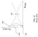
- FIGS. 1A–1Cillustrate the naming conventions, as well as the conventional focusing and scanning directions, in a typical transducer array used in medical imaging applications.
- the transducer 100is typically made up of multiple transducer elements 110 .
- Each of the transducer elements 110includes a plurality of individual transducer cells.
- the transducer elements 110are oriented such that their lengths are along the elevation axis, and their widths are along the azimuth axis.
- the transducer elements 110are adjacent to one another along the azimuth axis. As shown in FIG.
- a transducer array 100is conventionally focused to a focal spot 150 in the range direction and scanned in the azimuth direction electronically by applying an appropriate time delay to each of the transducer elements 110 .
- focus in the elevation directionhas conventionally been achieved with a mechanical lens 120 .
- This mechanical focusis sub-optimal because adequate elevation focus is only obtained over a relatively small portion of the usable range.
- time-delay focusing in the azimuth planeis possible over the entire field of view (for example 0.5–6 cm for a linear small parts probe)
- elevation focusis only obtained over a relatively small spatial region of peak focus 130 .
- a measure of the elevation focus achievable, as well as the depth of field over which good focus can be achieved,is often described by the term slice thickness.
- a convex lens 120focuses somewhere in the middle of the usable range, and the focus diverges, or becomes large, at ranges beyond the lens' peak focus 130 .
- This divergent lens focusingcreates volume averaging artifacts that obscure small cysts and other clinically relevant, yet small feature size, information.
- practical physical lensesare often lossy, which further decreases their effective use, because they are made from materials whose speed of sound is slower than the speed of sound in a body.
- U.S. Pat. No. 5,651,365 to Hanafy et al.teaches that slice thickness can be improved by using two sets of interleaved azimuthal transducer elements, each set having a different elevation aperture. One set is used for optimized focus at a certain range, and the second set is used for an optimized scan at a different range.
- this approachnegatively impacts at least one of efficiency, lateral resolution, or frame rate.
- U.S. Pat. No. 5,415,175 to Hanafy et al.teaches that by varying the thickness and curvature of a piezoelectric element along the elevation direction, that frequency dependent elevation focusing can be achieved. While this invention is known to those skilled in the art as resulting in ultrasound probes with improved slice thickness performance over conventional probes, the elevation aperture is problematic for low-frequency, relatively narrow-band signals such as those emanating from deep within the tissue. Furthermore, fabrication of these curved surfaces is challenging and consequently expensive.
- U.S. Pat. No. 6,381,197 to Savord et al.teaches that bias rows in the elevation direction of a microfabricated ultrasonic transducer (MUT) can be connected to bias sources, and that by using these bias sources to selectively energize elevation rows, the elevation aperture of a MUT can be controlled.
- the Savord patentfurther teaches that elevation apodization can be achieved by varying the gain in the elevation direction with the bias rows; inherent in the Savord apodization teaching is the complexity of multiple bias sources each at different voltage amplitudes, which is not desirable in practical applications.
- control of aperture and apodization by varying the magnitude of the bias on a MUTis effective only in receive operation.
- the MUTcannot be effectively turned off by bias amplitude alone and is operated outside of its linear range, that is, with the transmit pulse itself essentially biasing the transducer.
- the polarity of biascan modulate the phase, in elevation for example, of both the transmitted and received ultrasonic waveform.
- This bias-polarity-based phase modulationcan be used to effectively control the aperture of a MUT device by providing precise cancellation of both transmitted and received acoustic energy.
- This bias-polarity-based phase modulationcan also be used to create focus in the far field without using a mechanical lens, or to enhance focusing when combined with other lensing means. It can also be used to greatly simplify the design and implementation of probes with excellent slice thickness performance.
- the present inventionprovides a means to control the phase profile of a capacitive microfabricated ultrasonic transducer (cMUT) element or array of elements by varying the spatial distribution of the sign of the bias voltage on the cMUT.
- cMUTcapacitive microfabricated ultrasonic transducer
- the present inventionprovides a cMUT that can be focused in the elevation direction by varying the sign of the applied bias in the elevation direction.
- elevation focusingis achieved without the aid of a mechanical lens.
- the cMUT of the present inventionprovides enhanced multi-row focusing performance without the expense and complexity of the high-voltage switches required in multi-row probes and without the signal degradation that occurs when the RF signal passes through these lossy, high voltage switches.
- the present inventionprovides a simple and effective means for controlling the aperture of a microfabricated ultrasonic transducer in both transmit and receive operation.
- the present inventionalso provides a means for steering the cMUT transmission beam in the elevation direction.
- the present inventionachieves these and other goals by providing a method for controlling the elevation slice thickness in both the near field and the far field of a cMUT's usable range.
- the near field improvementis obtained by reducing both the effective radiating and receiving aperture.
- phase focusingis applied to reduce the slice thickness.
- aperture control and phase focusingthe elevation focal length can be altered to match the azimuth focus in each focal zone of the image.
- Reduction of the effective apertureis implemented by alternating the polarity of the bias on the elevation electrodes with sufficiently fine spatial resolution so as to cancel the fields from the affected elements.
- Per-focal-zone enhancement to far-field operationworks using a Fresnel zone plate.
- FIGS. 1A–1Cillustrate the naming conventions, as well as the conventional focusing and scanning directions, in a typical multi-element array transducer used in medical imaging applications;
- FIG. 2illustrates a top view of a transducer of one embodiment of the present invention
- FIG. 3illustrates a cross-section view of a transducer of one embodiment of the present invention
- FIG. 4illustrates the electrical schematic for the conventional transducer system
- FIG. 5illustrates the electrical schematic for the transducer system of an embodiment of the present invention
- FIGS. 6A–6Cillustrate the experimental design and experimental results verifying the aperture control aspect of the present invention
- FIGS. 7A–7Billustrate simulation results comparing conventional transducers with the present invention.
- FIG. 8illustrates bias voltage patterns corresponding to an embodiment of the present invention.
- the present inventionprovides a capacitive microfabricated ultrasonic transducer (cMUT) with control of elevation phase through bias polarity variation.
- cMUTcapacitive microfabricated ultrasonic transducer
- Such control of elevation phaseresults in simple ultrasonic probes with excellent slice thickness attributes.
- tight spatial variation of phaseresults in an effective way to achieve both transmit and receive aperture and apodization control.
- transducerscan achieve their elevation focus without the need of a lossy mechanical lens.
- An exemplary embodiment of the present inventionincludes a cMUT array, which is made up of transducer elements having transducer cells.
- the cMUT arrayis coupled to control circuitry that provides the tight spatial variation of phase using bias polarity.
- FIGS. 2 and 3illustrate a cMUT array formed according to an embodiment of the present invention. It will become apparent to one skilled in the art that any number of transducer cells can make up a transducer element, and any number of transducer elements can make up a cMUT array. The present invention is intended to incorporate this variability, and not be limited to the exemplary embodiments provided.
- FIG. 2illustrates a top view of an embodiment of a cMUT array 200 according to the present invention.
- the cMUT arraycontains two transducer elements 210 , with each of the transducer elements containing three transducer cells 201 , 202 and 203 .
- the cMUT array 200can, for example, be similar to that disclosed in U.S. Pat. No. 6,271,620 issued Aug. 7, 2001 to Ladabaum and entitled “Acoustic Transducer and Method of Making the Same.”
- Transducer element 210 Bcontains three transducer cells 201 B, 202 B and 203 B.
- Each of the transducer cells 201 B, 202 B and 203 Bhas a top electrode 241 B, 242 B and 243 B, respectively, and a bottom electrode (shown in FIG. 3 ), and a void region 231 B, 232 B and 233 B, respectively.
- Transducer cells 201 B, 202 B and 203 Bare interconnected along their top electrodes 241 B, 242 B and 243 B in the elevation direction by intra-element interconnects 251 B and 252 B.
- Corresponding transducer cells 201 A– 201 B, 202 A– 202 B and 203 A– 203 B of adjacent transducer elements 210 A– 210 Bare interconnected in the azimuth direction by inter-element interconnects 221 B, 222 B and 223 B to form elevation rows.
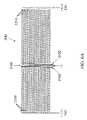
- the cross section 3 — 3 of FIG. 2is shown in FIG. 3 .
- FIG. 3illustrates a cross-section of transducer element 210 B of an embodiment of the present invention.
- transducer cells 201 B, 202 B and 203 Bare formed using the methods, for example, disclosed in co-owned U.S. patent application Ser. No. 09/898,035 filed Jul. 3, 2001 to Ladabaum and entitled “Method for Making Acoustic Transducer.”
- transducer cell 201 Bcan be constructed in the following manner.
- a layer of thermal oxide 320is grown over a substrate 310 .
- a first conductive layeris then deposited and etched to form the lower electrode 331 B. Thereafter, a lower insulation layer 340 is deposited.
- a sacrificial layeris deposited and etched, resulting in sacrificial portions that will ultimately become the void region 231 B.
- a middle insulation layer 350is deposited over the sacrificial portions.
- a second conductive layeris then deposited and etched to form the upper electrode 241 B.
- a top insulation layer 360is then deposited over the top electrode 241 B. At this point, the sacrificial portions are etched away through via holes, with the via holes being subsequently filled with insulation material 370 .
- the present inventionis not meant to limit the specific exemplary geometries of and methods of making the above-described transducer elements and cells. Additionally, the size and shape of the transducer cells are not meant to be limited to a single octagonal design; rather, each transducer cell could be a different size and a different shape from each of the other transducer cells.
- FIG. 4shows the traditional cMUT array 100 external circuit connections. As shown, typically one azimuth element connection 400 is connected to the top electrode of one series of transducer cells making up a transducer element 110 A of the traditional cMUT array 100 . All of the bottom electrodes of the cMUT array 100 are commonly connected 410 and, therefore, commonly biased.
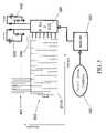
- FIG. 5shows the cMUT array 200 external circuit connections of an embodiment of the present invention.
- the top electrode of each transducer element 210 Ais connected externally to an azimuth element connection 400 .
- the bottom electrodes of corresponding transducer cells of adjacent transducer elementsare connected together to form elevation rows.
- Each elevation rowis externally connected 510 to a separate output channel of an N by 2 multiplexer 520 .
- the multiplexer 520 inputsare a positive 530 and negative 540 bias voltage.
- the multiplexer 520 control signalcomes from an EPROM 550 lookup table using a focal zone number 560 pointer.
- the sign of the bias to the elevation rowsis changed in order to invert the transmit signal for some of the elevation electrodes.
- Thishas the effect of creating a Fresnel zone plate. This focusing can be accomplished on transmission as well as reception. However, for simplicity, the following description will be in terms of the transmission, but reception operates in a similar manner.
- the multiplexerroutes either the positive or negative bias voltage to the N elevation row connections, based on a lookup table in the EPROM 550 .
- Each bias lineis an RF ground.
- the EPROM 550 addressis, for example, a number provided by the system, based on excitation voltage timing, which tells the probe which focal zone is in use, and optionally information about the center frequency and bandwidth of the excitation pulse. Data in the EPROM 550 converts this to the bias sign arrangement for a given focal zone, and the focal length of the zone plate is determined by these bias signs.
- the zone plateoperates similarly to a classical Fresnel lens, but is adapted to cMUT elevation focusing. For example, if the center of the elevation electrode is located at y i , then the phase ⁇ i required for focusing in a classical Fresnel lens is:
- ⁇ i2 ⁇ ⁇ ⁇ ⁇ ⁇ f c ⁇ r 2 + y i 2 - r , where f is the frequency, r is the desired focusing range, and c is the speed of sound in the medium of interest.
- the multiplexer-EPROM combination of the present inventioncan be replaced with any commonly known switching and selection circuitry combination.
- such componentsas: discrete relays, discrete transistors, solid state transistors and other solid state switches can be used.
- a manual pattern selection circuitcan be used instead of the EPROM storing multiple, real-time selectable, polarity patterns.
- the positive and negative bias voltages of the present inventioncan be hard-wired directly to the elevation rows or directly to the switching components.
- the polarity pattern for a particular applicationis pre-selected and the appropriate bias voltage directly connected to the appropriate elevation row, or elevation row switch, according to the pre-selected polarity pattern.
- the MUT device of the present inventioncan have a combination of hard-wired and switched bias voltages.
- the positive and negative bias voltagescan either be discretely generated off of the MUT device of the present invention, be generated locally with the MUT device of the present invention, or be a combination of discretely and locally generated.
- the bias voltagescan, for example, be included in the application probe handle or be generated elsewhere in the application system.
- the bias voltagescan, for example, be tied to the MUT device using wires, cables, harnesses, connectors, and the like.
- the bias voltage generation circuitrycan be included beside the MUT device, on the same or an adjacent die, or beneath the MUT device, within the MUT device substrate.
- each MUT elevation rowcan, for example, have its own particular bias voltage, that bias voltage being a particular combination of amplitude and polarity.
- the quantity of bias voltagescould outnumber the quantity of elevation rows, with some bias voltages being used for certain applications, while others are used for different applications.
- FIGS. 6A–6Cillustrate the feasibility of such an approach.
- FIG. 6Aillustrates a specific design of an experiment where 3 azimuth elements 210 A–C of a cMUT array 200 are connected to a transmit channel.
- the entire arrayconsists of 192 azimuth elements with 10 MHz center frequency, but only 3 azimuth elements are used in the presented experiment.
- the array 200contains two sets of elevation electrodes 220 A and 220 B. These electrodes are approximately 100 microns wide, and connect the cMUT cells of adjacent elements 210 A, 210 B, and 210 C in an alternating (i.e., interdigitated) manner to bias voltage V-biasL 540 or V-biasR 530 .
- Elements 210 A–Care each, for example, approximately 200 microns wide.
- FIG. 6Billustrates the relative strength of a received signal by a hydrophone when the array elements 210 A–C of FIG. 6A are biased uniformly in elevation, and when their elevation bias is alternated every 100 microns.
- the transmit pulse in this experimentwas small relative to the magnitude of V-bias.
- alternating the bias of cMUT elevation rowscan effectively turn off that section of the device, which is evidenced by the approximately 25 dB relative difference at 10 MHz.
- FIG. 6Cillustrates the feasibility of another aspect of the embodiment of FIG. 6A , which is that, when transmit voltages are large compared to the magnitude of V-bias, the transducer will operate non-linearly. At these relatively large transmit voltages, it may be necessary to apply different magnitudes of positive and negative bias voltages. As can be seen in FIG. 6C , 25 dB of isolation is possible, when alternating positive and negative bias voltages with magnitudes of 65V and 120V, respectively. Equal magnitude positive and negative bias voltages are less effective at canceling the radiated sound because the pressure created by a relatively large transmit voltage in the direction of bias is different from the pressure created by a relatively large transmit voltage in the opposite direction of the bias.
- FIGS. 7A–7Billustrate the improvements of the present invention over the traditional 1D probe and an exemplary, state-of-the-art, multi-row piezoelectric transducer array.
- the present inventionprovides an improved far-field beam width at both the ⁇ 3 dB and ⁇ 20 dB levels. This improvement stems from the use of the Fresnel lensing attributes of the present invention.
- the present inventionalso improves near-field improvements which are the result of the aperture control attributes verified in FIGS. 6A–6C .
- the simulations of FIGS. 7A–7Bare based on a design of 52 elevation rows, each approximately 100 microns in width, operated with different bias patterns at different focal zones.
- FIG. 8illustrates bias voltage patterns for the elevation control lines that can be used to enhance the 15 mm and 50 mm focus (in the range direction) of the probe simulated in FIGS. 7A–7B .
- FIGS. 7A–7Bit should be understood that there exists a virtually infinite combination of polarity patterns and bias voltages, and that these combination are meant to be included within the scope of the MUT device of the present invention.
- the traditional polymer lensbecomes unnecessary. Such a probe benefits from the fact that losses in the lens are avoided.
- elevation focusingis accomplished using both bias polarity aperture control and some form of mechanical lensing.
- This mechanical lensingcan be either conventional polymeric lensing or transducer curvature, as disclosed in co-owned and concurrently filed U.S. patent application Ser. No. 10/367,112 entitled “Microfabricated Transducers with Curvature and Method of Making the Same.” Fresnel lensing for focus optimization beyond the mechanical lens' focal zone can further be applied.
- the bias patterncan be changed between transmit and receive beams so that multi-focal-zone operation, as is known in the art of multi-row probes, is possible.
- the cMUT beamcan be steered in the elevation direction.
- the focusing of the cMUT beamcan be non-normal to the center of the cMUT elements in the elevation direction.
- the non-normalcyis such that the center point of the peak elevation focus in the elevation direction is off-center to the center of the transducer elements in the elevation direction.
Landscapes
- Engineering & Computer Science (AREA)
- Physics & Mathematics (AREA)
- Remote Sensing (AREA)
- Acoustics & Sound (AREA)
- Radar, Positioning & Navigation (AREA)
- Computer Networks & Wireless Communication (AREA)
- Multimedia (AREA)
- General Physics & Mathematics (AREA)
- Mechanical Engineering (AREA)
- Transducers For Ultrasonic Waves (AREA)
- Ultra Sonic Daignosis Equipment (AREA)
- Investigating Or Analyzing Materials By The Use Of Ultrasonic Waves (AREA)
- Measurement Of Velocity Or Position Using Acoustic Or Ultrasonic Waves (AREA)
Abstract
Description
where f is the frequency, r is the desired focusing range, and c is the speed of sound in the medium of interest. However, the present invention does not provide for continuous phase-shifting, as in a classical Fresnel lens. Rather, the present invention provides for discrete 180 degree phase shifts; it is essentially a cMUT zone plate. Therefore, the ideal continuous phase variation must be converted to discrete sign information to give the cMUT bias voltages: si=sign(mod(φi,2π)−π). Fortunately, the necessary elevation focusing with a multi-row probe is rather crude, so this simple arrangement reduces the unwanted out-of-plane energy to the −20 dB level that is sufficient to demonstrate all of the improvements in the image made possible with a practical multi-row transducer (i.e., 5–6 rows).
Claims (47)
Priority Applications (9)
| Application Number | Priority Date | Filing Date | Title |
|---|---|---|---|
| US10/367,106US7087023B2 (en) | 2003-02-14 | 2003-02-14 | Microfabricated ultrasonic transducers with bias polarity beam profile control and method of operating the same |
| EP04706549AEP1593115B1 (en) | 2003-02-14 | 2004-01-29 | Microfabricated ultrasonic transducers with bias polarity beam profile control |
| JP2006503208AJP4422718B2 (en) | 2003-02-14 | 2004-01-29 | Micromachined ultrasonic transducer with bias polar beam profile control |
| DE602004006232TDE602004006232T2 (en) | 2003-02-14 | 2004-01-29 | MICRO-MADE ULTRASONIC TRANSDUCERS WITH BIAS POLARITY BEAM PROFILING CONTROL |
| PCT/US2004/002740WO2004075165A1 (en) | 2003-02-14 | 2004-01-29 | Microfabricated ultrasonic transducers with bias polarity beam profile control |
| CN2004800072945ACN1833273B (en) | 2003-02-14 | 2004-01-29 | Microfabricated ultrasonic transducers with bias polarity beam profile control |
| US10/819,094US7780597B2 (en) | 2003-02-14 | 2004-04-05 | Method and apparatus for improving the performance of capacitive acoustic transducers using bias polarity control and multiple firings |
| US10/958,626US7635332B2 (en) | 2003-02-14 | 2004-10-04 | System and method of operating microfabricated ultrasonic transducers for harmonic imaging |
| US10/959,665US7618373B2 (en) | 2003-02-14 | 2004-10-04 | Microfabricated ultrasonic transducer array for 3-D imaging and method of operating the same |
Applications Claiming Priority (1)
| Application Number | Priority Date | Filing Date | Title |
|---|---|---|---|
| US10/367,106US7087023B2 (en) | 2003-02-14 | 2003-02-14 | Microfabricated ultrasonic transducers with bias polarity beam profile control and method of operating the same |
Related Child Applications (3)
| Application Number | Title | Priority Date | Filing Date |
|---|---|---|---|
| US10/819,094Continuation-In-PartUS7780597B2 (en) | 2003-02-14 | 2004-04-05 | Method and apparatus for improving the performance of capacitive acoustic transducers using bias polarity control and multiple firings |
| US10/891,094Continuation-In-PartUS7042116B2 (en) | 1995-06-26 | 2004-07-15 | Series connected light string with filament shunting |
| US10/959,665Continuation-In-PartUS7618373B2 (en) | 2003-02-14 | 2004-10-04 | Microfabricated ultrasonic transducer array for 3-D imaging and method of operating the same |
Publications (2)
| Publication Number | Publication Date |
|---|---|
| US20040160144A1 US20040160144A1 (en) | 2004-08-19 |
| US7087023B2true US7087023B2 (en) | 2006-08-08 |
Family
ID=32849901
Family Applications (1)
| Application Number | Title | Priority Date | Filing Date |
|---|---|---|---|
| US10/367,106Expired - Fee RelatedUS7087023B2 (en) | 2003-02-14 | 2003-02-14 | Microfabricated ultrasonic transducers with bias polarity beam profile control and method of operating the same |
Country Status (6)
| Country | Link |
|---|---|
| US (1) | US7087023B2 (en) |
| EP (1) | EP1593115B1 (en) |
| JP (1) | JP4422718B2 (en) |
| CN (1) | CN1833273B (en) |
| DE (1) | DE602004006232T2 (en) |
| WO (1) | WO2004075165A1 (en) |
Cited By (58)
| Publication number | Priority date | Publication date | Assignee | Title |
|---|---|---|---|---|
| US20040190377A1 (en)* | 2003-03-06 | 2004-09-30 | Lewandowski Robert Stephen | Method and means for isolating elements of a sensor array |
| US20050043627A1 (en)* | 2003-07-17 | 2005-02-24 | Angelsen Bjorn A.J. | Curved ultrasound transducer arrays manufactured with planar technology |
| US20050119575A1 (en)* | 2003-02-14 | 2005-06-02 | Igal Ladabaum | Microfabricated ultrasonic transducer array for 3-D imaging and method of operating the same |
| US20050124882A1 (en)* | 2003-02-14 | 2005-06-09 | Igal Ladabaum | System and method of operating microfabricated ultrasonic transducers for harmonic imaging |
| US20050203409A1 (en)* | 2004-03-12 | 2005-09-15 | Siemens Medical Solutions Usa, Inc. | Electrical interconnections and methods for membrane ultrasound transducers |
| US20050215909A1 (en)* | 2004-03-19 | 2005-09-29 | Siemens Medical Solutions Usa, Inc. | Electric field control for capacitive micromachined ultrasound transducers |
| US20060173342A1 (en)* | 2003-02-14 | 2006-08-03 | Satchi Panda | Method and apparatus for improving the performance of capacitive acoustic transducers using bias polarity control and multiple firings |
| US20070167786A1 (en)* | 2005-12-20 | 2007-07-19 | General Electric Company | Fresnel zone imaging system and method |
| US20070238999A1 (en)* | 2006-02-06 | 2007-10-11 | Specht Donald F | Method and apparatus to visualize the coronary arteries using ultrasound |
| US20080064959A1 (en)* | 2004-10-15 | 2008-03-13 | Hitachi Medical Corporation | Ultrasonic Diagnostic Apparatus |
| US20080103393A1 (en)* | 2006-10-25 | 2008-05-01 | Specht Donald F | Method and apparatus to produce ultrasonic images using multiple apertures |
| US20080283945A1 (en)* | 2007-05-16 | 2008-11-20 | Hitachi, Ltd | Semiconductor device |
| US20090080292A1 (en)* | 2007-09-20 | 2009-03-26 | Wagner Paul A | Microfabricated acoustic transducer with a multilayer electrode |
| US20090126183A1 (en)* | 2005-06-17 | 2009-05-21 | Industrial Technology Research Institute | Method of fabricating a polymer-based capacitive ultrasonic transducer |
| US20090234220A1 (en)* | 2008-03-12 | 2009-09-17 | Simens Aktiengesellschaft | Catheter and associated medical examination and treatment device |
| US20090234445A1 (en)* | 2008-03-12 | 2009-09-17 | Siemens Aktiengesellschaft | Catheter device and associated Medical examination and treatment apparatus as well as associated method |
| US20090234444A1 (en)* | 2008-03-12 | 2009-09-17 | Michael Maschke | Method and apparatus for conducting an interventional procedure involving heart valves using a robot-based x-ray device |
| US20100123366A1 (en)* | 2008-11-19 | 2010-05-20 | Canon Kabushiki Kaisha | Electromechanical transducer and method for manufacturing the same |
| US20100198070A1 (en)* | 2007-07-11 | 2010-08-05 | Katsunori Asafusa | Ultrasonic probe and ultrasonic diagnostic apparatus |
| US20100240944A1 (en)* | 2009-03-23 | 2010-09-23 | Michael Maschke | Blood pump, medical apparatus having a blood pump and method for assisting the positioning of a blood pump |
| US20100241147A1 (en)* | 2009-03-23 | 2010-09-23 | Michael Maschke | Catheter and medical apparatus as well as method for assisting an intervention to remove plaque |
| US7809420B2 (en) | 2003-06-25 | 2010-10-05 | Nellcor Puritan Bennett Llc | Hat-based oximeter sensor |
| US20100268503A1 (en)* | 2009-04-14 | 2010-10-21 | Specht Donald F | Multiple Aperture Ultrasound Array Alignment Fixture |
| US7822453B2 (en) | 2002-10-01 | 2010-10-26 | Nellcor Puritan Bennett Llc | Forehead sensor placement |
| US20110196395A1 (en)* | 2010-02-08 | 2011-08-11 | Michael Maschke | Method for displaying an image of the inside of a vessel lying in front of an expander device and display device corresponding hereto |
| US20110230765A1 (en)* | 2010-03-17 | 2011-09-22 | Siemens Medical Solutions Usa, Inc. | Motion Synchronized Destruction for Three-Dimensional Reperfusion Mapping in Medical Diagnostic Ultrasound Imaging |
| WO2012087678A2 (en) | 2010-12-23 | 2012-06-28 | Analog Devices, Inc. | Acoustic transducer chip |
| US8257274B2 (en) | 2008-09-25 | 2012-09-04 | Nellcor Puritan Bennett Llc | Medical sensor and technique for using the same |
| US8364220B2 (en) | 2008-09-25 | 2013-01-29 | Covidien Lp | Medical sensor and technique for using the same |
| US8412297B2 (en) | 2003-10-01 | 2013-04-02 | Covidien Lp | Forehead sensor placement |
| US8515515B2 (en) | 2009-03-25 | 2013-08-20 | Covidien Lp | Medical sensor with compressible light barrier and technique for using the same |
| US8602993B2 (en) | 2008-08-08 | 2013-12-10 | Maui Imaging, Inc. | Imaging with multiple aperture medical ultrasound and synchronization of add-on systems |
| US8764664B2 (en) | 2005-11-28 | 2014-07-01 | Vizyontech Imaging, Inc. | Methods and apparatus for conformable medical data acquisition pad and configurable imaging system |
| US8781548B2 (en) | 2009-03-31 | 2014-07-15 | Covidien Lp | Medical sensor with flexible components and technique for using the same |
| US9146313B2 (en) | 2006-09-14 | 2015-09-29 | Maui Imaging, Inc. | Point source transmission and speed-of-sound correction using multi-aperature ultrasound imaging |
| US9220478B2 (en) | 2010-04-14 | 2015-12-29 | Maui Imaging, Inc. | Concave ultrasound transducers and 3D arrays |
| US9265484B2 (en) | 2011-12-29 | 2016-02-23 | Maui Imaging, Inc. | M-mode ultrasound imaging of arbitrary paths |
| US9282945B2 (en) | 2009-04-14 | 2016-03-15 | Maui Imaging, Inc. | Calibration of ultrasound probes |
| US9339256B2 (en) | 2007-10-01 | 2016-05-17 | Maui Imaging, Inc. | Determining material stiffness using multiple aperture ultrasound |
| US20160144402A1 (en)* | 2014-11-20 | 2016-05-26 | Canon Kabushiki Kaisha | Capacitive transducer and sample information acquisition apparatus |
| US9510806B2 (en) | 2013-03-13 | 2016-12-06 | Maui Imaging, Inc. | Alignment of ultrasound transducer arrays and multiple aperture probe assembly |
| US9572549B2 (en) | 2012-08-10 | 2017-02-21 | Maui Imaging, Inc. | Calibration of multiple aperture ultrasound probes |
| US9668714B2 (en) | 2010-04-14 | 2017-06-06 | Maui Imaging, Inc. | Systems and methods for improving ultrasound image quality by applying weighting factors |
| US9788813B2 (en) | 2010-10-13 | 2017-10-17 | Maui Imaging, Inc. | Multiple aperture probe internal apparatus and cable assemblies |
| US9883848B2 (en) | 2013-09-13 | 2018-02-06 | Maui Imaging, Inc. | Ultrasound imaging using apparent point-source transmit transducer |
| US9986969B2 (en) | 2012-09-06 | 2018-06-05 | Maui Imaging, Inc. | Ultrasound imaging system memory architecture |
| US10042044B2 (en)* | 2013-09-30 | 2018-08-07 | Seiko Epson Corporation | Ultrasonic device, probe, electronic device, and ultrasonic imaging apparatus |
| US10226234B2 (en) | 2011-12-01 | 2019-03-12 | Maui Imaging, Inc. | Motion detection using ping-based and multiple aperture doppler ultrasound |
| US10401493B2 (en) | 2014-08-18 | 2019-09-03 | Maui Imaging, Inc. | Network-based ultrasound imaging system |
| US10856846B2 (en) | 2016-01-27 | 2020-12-08 | Maui Imaging, Inc. | Ultrasound imaging with sparse array probes |
| US10996332B2 (en) | 2015-09-08 | 2021-05-04 | Dalhousie University | Systems and methods of combined phased-array and Fresnel zone plate beamforming employing delay-corrected Fresnel sub-apertures |
| US11061124B2 (en) | 2016-10-21 | 2021-07-13 | The Governors Of The University Of Alberta | System and method for ultrasound imaging |
| US11150344B2 (en) | 2018-01-26 | 2021-10-19 | Roger Zemp | 3D imaging using a bias-sensitive crossed-electrode array |
| US12167209B2 (en) | 2012-09-06 | 2024-12-10 | Maui Imaging, Inc. | Ultrasound imaging system memory architecture |
| US12190627B2 (en) | 2015-03-30 | 2025-01-07 | Maui Imaging, Inc. | Ultrasound imaging systems and methods for detecting object motion |
| US12343208B2 (en) | 2021-09-09 | 2025-07-01 | Roger Zemp | Ultrasound imaging using a bias-switchable row-column array transducer |
| US12350710B2 (en) | 2018-11-16 | 2025-07-08 | Vermon S.A. | Capacitive micromachined ultrasonic transducer and method of manufacturing the same |
| US12396706B2 (en) | 2023-10-04 | 2025-08-26 | Clinisonix Inc. | Synthetic phase alternating row-column transducer array |
Families Citing this family (30)
| Publication number | Priority date | Publication date | Assignee | Title |
|---|---|---|---|---|
| US7443765B2 (en)* | 2003-03-06 | 2008-10-28 | General Electric Company | Reconfigurable linear sensor arrays for reduced channel count |
| WO2006121851A2 (en)* | 2005-05-05 | 2006-11-16 | Volcano Corporation | Capacitive microfabricated ultrasound transducer-based intravascular ultrasound probes |
| CN101160098B (en)* | 2005-05-09 | 2011-01-05 | 株式会社日立医药 | Ultrasonograph |
| US7229251B2 (en)* | 2005-05-31 | 2007-06-12 | Sikorsky Aircraft Corporation | Rotor hub fairing system for a counter-rotating, coaxial rotor system |
| US20070079658A1 (en)* | 2005-09-23 | 2007-04-12 | Siemens Medical Solutions Usa, Inc. | Rotating aperture for ultrasound imaging with a capacitive membrane or electrostrictive ultrasound transducer |
| JP4776349B2 (en)* | 2005-11-14 | 2011-09-21 | 株式会社日立メディコ | Ultrasonic imaging device |
| US20090118619A1 (en)* | 2006-02-23 | 2009-05-07 | Mitsuhiro Oshiki | Ultrasonic diagnostic apparatus and ultrasonic diagnostic method |
| JP4699259B2 (en)* | 2006-03-31 | 2011-06-08 | 株式会社日立製作所 | Ultrasonic transducer |
| US7956510B2 (en)* | 2006-04-04 | 2011-06-07 | Kolo Technologies, Inc. | Modulation in micromachined ultrasonic transducers |
| JP4852356B2 (en)* | 2006-06-27 | 2012-01-11 | 株式会社日立メディコ | Ultrasonic diagnostic equipment |
| US8641628B2 (en)* | 2007-09-26 | 2014-02-04 | Siemens Medical Solutions Usa, Inc. | Aperture synthesis using cMUTs |
| US8133182B2 (en) | 2008-09-09 | 2012-03-13 | Siemens Medical Solutions Usa, Inc. | Multi-dimensional transducer array and beamforming for ultrasound imaging |
| JP5397670B2 (en)* | 2008-09-16 | 2014-01-22 | 株式会社ニデック | Non-contact ultrasonic tonometer |
| JP5473579B2 (en) | 2009-12-11 | 2014-04-16 | キヤノン株式会社 | Control device for capacitive electromechanical transducer and control method for capacitive electromechanical transducer |
| KR20120080882A (en)* | 2011-01-10 | 2012-07-18 | 삼성전자주식회사 | Acoustic transducer and method of driving the same |
| JP6024156B2 (en)* | 2012-03-30 | 2016-11-09 | セイコーエプソン株式会社 | Ultrasonic measuring device, electronic device, diagnostic device and ultrasonic device |
| JP2014023670A (en)* | 2012-07-26 | 2014-02-06 | Ge Medical Systems Global Technology Co Llc | Ultrasonic diagnostic apparatus and control program for the same |
| JP6011235B2 (en)* | 2012-10-17 | 2016-10-19 | セイコーエプソン株式会社 | Ultrasonic measuring device, probe head, ultrasonic probe, electronic device and ultrasonic diagnostic device |
| DE102013217362A1 (en)* | 2013-08-30 | 2015-03-05 | Robert Bosch Gmbh | sensor arrangement |
| US9987661B2 (en) | 2015-12-02 | 2018-06-05 | Butterfly Network, Inc. | Biasing of capacitive micromachined ultrasonic transducers (CMUTs) and related apparatus and methods |
| CN105411625B (en)* | 2015-12-28 | 2019-06-07 | 中国科学院苏州生物医学工程技术研究所 | Diagnosis and treatment integrative ultrasonic system based on capacitance type micromachined ultrasonic energy converter planar battle array |
| JP6705180B2 (en)* | 2016-01-21 | 2020-06-03 | コニカミノルタ株式会社 | Ultrasonic diagnostic equipment |
| WO2017149421A1 (en)* | 2016-03-03 | 2017-09-08 | Koninklijke Philips N.V. | Ultrasonic cmut transducer array with improved depth of field |
| KR102529634B1 (en)* | 2016-12-15 | 2023-05-04 | 달하우지 유니버서티 | Systems and methods for ultrasonic beamforming using coherent synthetic fresnel focusing |
| EP4289521A3 (en)* | 2016-12-22 | 2024-03-27 | Koninklijke Philips N.V. | Systems and methods of operation of capacitive radio frequency micro-electromechanical switches |
| TW201904677A (en) | 2017-06-23 | 2019-02-01 | 美商蝴蝶網路公司 | Differential ultrasonic transducer element for ultrasonic devices |
| US10613058B2 (en)* | 2017-06-27 | 2020-04-07 | Kolo Medical, Ltd. | CMUT signal separation with multi-level bias control |
| EP3597313A1 (en)* | 2018-07-18 | 2020-01-22 | Koninklijke Philips N.V. | Ultrasound imaging system using an array of transducer elements and an imaging method |
| EP3827906B1 (en) | 2019-11-29 | 2025-09-17 | Imec VZW | A phased array ultrasound device for creating a pressure focus point |
| CN112683389B (en)* | 2021-01-13 | 2022-11-01 | 山东省科学院海洋仪器仪表研究所 | Longitudinal vibration vector hydrophone |
Citations (19)
| Publication number | Priority date | Publication date | Assignee | Title |
|---|---|---|---|---|
| US4670683A (en) | 1985-08-20 | 1987-06-02 | North American Philips Corporation | Electronically adjustable mechanical lens for ultrasonic linear array and phased array imaging |
| US4736630A (en) | 1985-08-05 | 1988-04-12 | Hitachi, Ltd. | Apparatus and method for sending out and receiving ultrasonic wave signals |
| US4888746A (en) | 1987-09-24 | 1989-12-19 | Richard Wolf Gmbh | Focussing ultrasound transducer |
| US5301168A (en) | 1993-01-19 | 1994-04-05 | Hewlett-Packard Company | Ultrasonic transducer system |
| US5415175A (en) | 1993-09-07 | 1995-05-16 | Acuson Corporation | Broadband phased array transducer design with frequency controlled two dimension capability and methods for manufacture thereof |
| US5490512A (en) | 1994-06-16 | 1996-02-13 | Siemens Medical Systems, Inc. | Elevation direction focusing in ultrasound transducer arrays |
| US5619476A (en) | 1994-10-21 | 1997-04-08 | The Board Of Trustees Of The Leland Stanford Jr. Univ. | Electrostatic ultrasonic transducer |
| US5627580A (en)* | 1993-07-26 | 1997-05-06 | Texas Instruments Incorporated | System and method for enhanced printing |
| US5651365A (en) | 1995-06-07 | 1997-07-29 | Acuson Corporation | Phased array transducer design and method for manufacture thereof |
| US5671746A (en) | 1996-07-29 | 1997-09-30 | Acuson Corporation | Elevation steerable ultrasound transducer array |
| US5768007A (en)* | 1995-09-11 | 1998-06-16 | Texas Instruments Incorporated | Phase matched reset for digital micro-mirror device |
| US5894452A (en) | 1994-10-21 | 1999-04-13 | The Board Of Trustees Of The Leland Stanford Junior University | Microfabricated ultrasonic immersion transducer |
| US5982709A (en) | 1998-03-31 | 1999-11-09 | The Board Of Trustees Of The Leland Stanford Junior University | Acoustic transducers and method of microfabrication |
| EP0978822A2 (en) | 1998-08-03 | 2000-02-09 | Vingmed Sound A/S | A multi-dimensional transducer array apparatus |
| US6172797B1 (en)* | 1995-06-19 | 2001-01-09 | Reflectivity, Inc. | Double substrate reflective spatial light modulator with self-limiting micro-mechanical elements |
| US6246158B1 (en)* | 1999-06-24 | 2001-06-12 | Sensant Corporation | Microfabricated transducers formed over other circuit components on an integrated circuit chip and methods for making the same |
| US6271620B1 (en)* | 1999-05-20 | 2001-08-07 | Sen Corporation | Acoustic transducer and method of making the same |
| US6328697B1 (en)* | 2000-06-15 | 2001-12-11 | Atl Ultrasound, Inc. | Capacitive micromachined ultrasonic transducers with improved capacitive response |
| US6381197B1 (en) | 1999-05-11 | 2002-04-30 | Bernard J Savord | Aperture control and apodization in a micro-machined ultrasonic transducer |
- 2003
- 2003-02-14USUS10/367,106patent/US7087023B2/ennot_activeExpired - Fee Related
- 2004
- 2004-01-29EPEP04706549Apatent/EP1593115B1/ennot_activeExpired - Lifetime
- 2004-01-29JPJP2006503208Apatent/JP4422718B2/ennot_activeExpired - Fee Related
- 2004-01-29CNCN2004800072945Apatent/CN1833273B/ennot_activeExpired - Fee Related
- 2004-01-29DEDE602004006232Tpatent/DE602004006232T2/ennot_activeExpired - Lifetime
- 2004-01-29WOPCT/US2004/002740patent/WO2004075165A1/enactiveIP Right Grant
Patent Citations (21)
| Publication number | Priority date | Publication date | Assignee | Title |
|---|---|---|---|---|
| US4736630A (en) | 1985-08-05 | 1988-04-12 | Hitachi, Ltd. | Apparatus and method for sending out and receiving ultrasonic wave signals |
| US4670683A (en) | 1985-08-20 | 1987-06-02 | North American Philips Corporation | Electronically adjustable mechanical lens for ultrasonic linear array and phased array imaging |
| US4888746A (en) | 1987-09-24 | 1989-12-19 | Richard Wolf Gmbh | Focussing ultrasound transducer |
| US5301168A (en) | 1993-01-19 | 1994-04-05 | Hewlett-Packard Company | Ultrasonic transducer system |
| US5627580A (en)* | 1993-07-26 | 1997-05-06 | Texas Instruments Incorporated | System and method for enhanced printing |
| US5415175A (en) | 1993-09-07 | 1995-05-16 | Acuson Corporation | Broadband phased array transducer design with frequency controlled two dimension capability and methods for manufacture thereof |
| US5490512A (en) | 1994-06-16 | 1996-02-13 | Siemens Medical Systems, Inc. | Elevation direction focusing in ultrasound transducer arrays |
| US5894452A (en) | 1994-10-21 | 1999-04-13 | The Board Of Trustees Of The Leland Stanford Junior University | Microfabricated ultrasonic immersion transducer |
| US5619476A (en) | 1994-10-21 | 1997-04-08 | The Board Of Trustees Of The Leland Stanford Jr. Univ. | Electrostatic ultrasonic transducer |
| US5651365A (en) | 1995-06-07 | 1997-07-29 | Acuson Corporation | Phased array transducer design and method for manufacture thereof |
| US6172797B1 (en)* | 1995-06-19 | 2001-01-09 | Reflectivity, Inc. | Double substrate reflective spatial light modulator with self-limiting micro-mechanical elements |
| US5768007A (en)* | 1995-09-11 | 1998-06-16 | Texas Instruments Incorporated | Phase matched reset for digital micro-mirror device |
| US5671746A (en) | 1996-07-29 | 1997-09-30 | Acuson Corporation | Elevation steerable ultrasound transducer array |
| US5982709A (en) | 1998-03-31 | 1999-11-09 | The Board Of Trustees Of The Leland Stanford Junior University | Acoustic transducers and method of microfabrication |
| EP0978822A2 (en) | 1998-08-03 | 2000-02-09 | Vingmed Sound A/S | A multi-dimensional transducer array apparatus |
| US6381197B1 (en) | 1999-05-11 | 2002-04-30 | Bernard J Savord | Aperture control and apodization in a micro-machined ultrasonic transducer |
| US6271620B1 (en)* | 1999-05-20 | 2001-08-07 | Sen Corporation | Acoustic transducer and method of making the same |
| US6571445B2 (en)* | 1999-05-20 | 2003-06-03 | Igal Ladabaum | Method for making acoustic transducer |
| US6246158B1 (en)* | 1999-06-24 | 2001-06-12 | Sensant Corporation | Microfabricated transducers formed over other circuit components on an integrated circuit chip and methods for making the same |
| US6562650B2 (en)* | 1999-06-24 | 2003-05-13 | Sensant Corporation | Microfabricated transducers formed over other circuit components on an integrated circuit chip and methods for making the same |
| US6328697B1 (en)* | 2000-06-15 | 2001-12-11 | Atl Ultrasound, Inc. | Capacitive micromachined ultrasonic transducers with improved capacitive response |
Non-Patent Citations (1)
| Title |
|---|
| ISR PCT/US2004/002740 Mailed Jul. 7, 2004. |
Cited By (109)
| Publication number | Priority date | Publication date | Assignee | Title |
|---|---|---|---|---|
| US7822453B2 (en) | 2002-10-01 | 2010-10-26 | Nellcor Puritan Bennett Llc | Forehead sensor placement |
| US7618373B2 (en)* | 2003-02-14 | 2009-11-17 | Siemens Medical Solutions Usa, Inc. | Microfabricated ultrasonic transducer array for 3-D imaging and method of operating the same |
| US20050119575A1 (en)* | 2003-02-14 | 2005-06-02 | Igal Ladabaum | Microfabricated ultrasonic transducer array for 3-D imaging and method of operating the same |
| US20050124882A1 (en)* | 2003-02-14 | 2005-06-09 | Igal Ladabaum | System and method of operating microfabricated ultrasonic transducers for harmonic imaging |
| US7780597B2 (en) | 2003-02-14 | 2010-08-24 | Siemens Medical Solutions Usa, Inc. | Method and apparatus for improving the performance of capacitive acoustic transducers using bias polarity control and multiple firings |
| US20060173342A1 (en)* | 2003-02-14 | 2006-08-03 | Satchi Panda | Method and apparatus for improving the performance of capacitive acoustic transducers using bias polarity control and multiple firings |
| US7635332B2 (en) | 2003-02-14 | 2009-12-22 | Siemens Medical Solutions Usa, Inc. | System and method of operating microfabricated ultrasonic transducers for harmonic imaging |
| US20040190377A1 (en)* | 2003-03-06 | 2004-09-30 | Lewandowski Robert Stephen | Method and means for isolating elements of a sensor array |
| US7979102B2 (en) | 2003-06-25 | 2011-07-12 | Nellcor Puritan Bennett Llc | Hat-based oximeter sensor |
| US7877126B2 (en) | 2003-06-25 | 2011-01-25 | Nellcor Puritan Bennett Llc | Hat-based oximeter sensor |
| US7813779B2 (en) | 2003-06-25 | 2010-10-12 | Nellcor Puritan Bennett Llc | Hat-based oximeter sensor |
| US7809420B2 (en) | 2003-06-25 | 2010-10-05 | Nellcor Puritan Bennett Llc | Hat-based oximeter sensor |
| US7877127B2 (en) | 2003-06-25 | 2011-01-25 | Nellcor Puritan Bennett Llc | Hat-based oximeter sensor |
| US20050043627A1 (en)* | 2003-07-17 | 2005-02-24 | Angelsen Bjorn A.J. | Curved ultrasound transducer arrays manufactured with planar technology |
| US8412297B2 (en) | 2003-10-01 | 2013-04-02 | Covidien Lp | Forehead sensor placement |
| US7427825B2 (en)* | 2004-03-12 | 2008-09-23 | Siemens Medical Solutions Usa, Inc. | Electrical interconnections and methods for membrane ultrasound transducers |
| US20050203409A1 (en)* | 2004-03-12 | 2005-09-15 | Siemens Medical Solutions Usa, Inc. | Electrical interconnections and methods for membrane ultrasound transducers |
| US20050215909A1 (en)* | 2004-03-19 | 2005-09-29 | Siemens Medical Solutions Usa, Inc. | Electric field control for capacitive micromachined ultrasound transducers |
| US20080064959A1 (en)* | 2004-10-15 | 2008-03-13 | Hitachi Medical Corporation | Ultrasonic Diagnostic Apparatus |
| US8465430B2 (en)* | 2004-10-15 | 2013-06-18 | Hitachi Medical Corporation | Ultrasonic diagnostic apparatus |
| US20090126183A1 (en)* | 2005-06-17 | 2009-05-21 | Industrial Technology Research Institute | Method of fabricating a polymer-based capacitive ultrasonic transducer |
| US8764664B2 (en) | 2005-11-28 | 2014-07-01 | Vizyontech Imaging, Inc. | Methods and apparatus for conformable medical data acquisition pad and configurable imaging system |
| US20070167786A1 (en)* | 2005-12-20 | 2007-07-19 | General Electric Company | Fresnel zone imaging system and method |
| US8038620B2 (en)* | 2005-12-20 | 2011-10-18 | General Electric Company | Fresnel zone imaging system and method |
| US9582876B2 (en) | 2006-02-06 | 2017-02-28 | Maui Imaging, Inc. | Method and apparatus to visualize the coronary arteries using ultrasound |
| US9192355B2 (en) | 2006-02-06 | 2015-11-24 | Maui Imaging, Inc. | Multiple aperture ultrasound array alignment fixture |
| US20070238999A1 (en)* | 2006-02-06 | 2007-10-11 | Specht Donald F | Method and apparatus to visualize the coronary arteries using ultrasound |
| US8105239B2 (en) | 2006-02-06 | 2012-01-31 | Maui Imaging, Inc. | Method and apparatus to visualize the coronary arteries using ultrasound |
| US9146313B2 (en) | 2006-09-14 | 2015-09-29 | Maui Imaging, Inc. | Point source transmission and speed-of-sound correction using multi-aperature ultrasound imaging |
| US9526475B2 (en) | 2006-09-14 | 2016-12-27 | Maui Imaging, Inc. | Point source transmission and speed-of-sound correction using multi-aperture ultrasound imaging |
| US9986975B2 (en) | 2006-09-14 | 2018-06-05 | Maui Imaging, Inc. | Point source transmission and speed-of-sound correction using multi-aperture ultrasound imaging |
| US10130333B2 (en) | 2006-10-25 | 2018-11-20 | Maui Imaging, Inc. | Method and apparatus to produce ultrasonic images using multiple apertures |
| US9420994B2 (en) | 2006-10-25 | 2016-08-23 | Maui Imaging, Inc. | Method and apparatus to produce ultrasonic images using multiple apertures |
| US8007439B2 (en) | 2006-10-25 | 2011-08-30 | Maui Imaging, Inc. | Method and apparatus to produce ultrasonic images using multiple apertures |
| US20080103393A1 (en)* | 2006-10-25 | 2008-05-01 | Specht Donald F | Method and apparatus to produce ultrasonic images using multiple apertures |
| US8684936B2 (en) | 2006-10-25 | 2014-04-01 | Maui Imaging, Inc. | Method and apparatus to produce ultrasonic images using multiple apertures |
| US8277383B2 (en) | 2006-10-25 | 2012-10-02 | Maui Imaging, Inc. | Method and apparatus to produce ultrasonic images using multiple apertures |
| US9072495B2 (en) | 2006-10-25 | 2015-07-07 | Maui Imaging, Inc. | Method and apparatus to produce ultrasonic images using multiple apertures |
| US20080283945A1 (en)* | 2007-05-16 | 2008-11-20 | Hitachi, Ltd | Semiconductor device |
| US7923795B2 (en)* | 2007-05-16 | 2011-04-12 | Hitachi, Ltd. | Ultrasonic transducer device |
| US20100198070A1 (en)* | 2007-07-11 | 2010-08-05 | Katsunori Asafusa | Ultrasonic probe and ultrasonic diagnostic apparatus |
| US9089873B2 (en)* | 2007-07-11 | 2015-07-28 | Hitachi Medical Corporation | Ultrasonic probe and ultrasonic diagnostic apparatus |
| US20090080292A1 (en)* | 2007-09-20 | 2009-03-26 | Wagner Paul A | Microfabricated acoustic transducer with a multilayer electrode |
| US7839722B2 (en) | 2007-09-20 | 2010-11-23 | Siemens Medical Solutions Usa, Inc. | Microfabricated acoustic transducer with a multilayer electrode |
| US10675000B2 (en) | 2007-10-01 | 2020-06-09 | Maui Imaging, Inc. | Determining material stiffness using multiple aperture ultrasound |
| US9339256B2 (en) | 2007-10-01 | 2016-05-17 | Maui Imaging, Inc. | Determining material stiffness using multiple aperture ultrasound |
| US8792964B2 (en) | 2008-03-12 | 2014-07-29 | Siemens Aktiengesellschaft | Method and apparatus for conducting an interventional procedure involving heart valves using a robot-based X-ray device |
| US20090234220A1 (en)* | 2008-03-12 | 2009-09-17 | Simens Aktiengesellschaft | Catheter and associated medical examination and treatment device |
| US20090234444A1 (en)* | 2008-03-12 | 2009-09-17 | Michael Maschke | Method and apparatus for conducting an interventional procedure involving heart valves using a robot-based x-ray device |
| US20090234445A1 (en)* | 2008-03-12 | 2009-09-17 | Siemens Aktiengesellschaft | Catheter device and associated Medical examination and treatment apparatus as well as associated method |
| US8602993B2 (en) | 2008-08-08 | 2013-12-10 | Maui Imaging, Inc. | Imaging with multiple aperture medical ultrasound and synchronization of add-on systems |
| US8257274B2 (en) | 2008-09-25 | 2012-09-04 | Nellcor Puritan Bennett Llc | Medical sensor and technique for using the same |
| US8364220B2 (en) | 2008-09-25 | 2013-01-29 | Covidien Lp | Medical sensor and technique for using the same |
| US8760031B2 (en)* | 2008-11-19 | 2014-06-24 | Canon Kabushiki Kaisha | Electromechanical transducer and method for manufacturing the same which suppresses lowering of sensitivity while a protective layer is formed |
| US20100123366A1 (en)* | 2008-11-19 | 2010-05-20 | Canon Kabushiki Kaisha | Electromechanical transducer and method for manufacturing the same |
| US8241199B2 (en) | 2009-03-23 | 2012-08-14 | Siemens Aktiengesellschaft | Blood pump, medical apparatus having a blood pump and method for assisting the positioning of a blood pump |
| US20100241147A1 (en)* | 2009-03-23 | 2010-09-23 | Michael Maschke | Catheter and medical apparatus as well as method for assisting an intervention to remove plaque |
| US8257375B2 (en) | 2009-03-23 | 2012-09-04 | Siemens Aktiengesellschaft | Catheter and medical apparatus as well as method for assisting an intervention to remove plaque |
| US20100240944A1 (en)* | 2009-03-23 | 2010-09-23 | Michael Maschke | Blood pump, medical apparatus having a blood pump and method for assisting the positioning of a blood pump |
| US8515515B2 (en) | 2009-03-25 | 2013-08-20 | Covidien Lp | Medical sensor with compressible light barrier and technique for using the same |
| US8781548B2 (en) | 2009-03-31 | 2014-07-15 | Covidien Lp | Medical sensor with flexible components and technique for using the same |
| US10206662B2 (en) | 2009-04-14 | 2019-02-19 | Maui Imaging, Inc. | Calibration of ultrasound probes |
| US8473239B2 (en) | 2009-04-14 | 2013-06-25 | Maui Imaging, Inc. | Multiple aperture ultrasound array alignment fixture |
| US11051791B2 (en)* | 2009-04-14 | 2021-07-06 | Maui Imaging, Inc. | Calibration of ultrasound probes |
| US9282945B2 (en) | 2009-04-14 | 2016-03-15 | Maui Imaging, Inc. | Calibration of ultrasound probes |
| US20100268503A1 (en)* | 2009-04-14 | 2010-10-21 | Specht Donald F | Multiple Aperture Ultrasound Array Alignment Fixture |
| US20110196395A1 (en)* | 2010-02-08 | 2011-08-11 | Michael Maschke | Method for displaying an image of the inside of a vessel lying in front of an expander device and display device corresponding hereto |
| US11998395B2 (en) | 2010-02-18 | 2024-06-04 | Maui Imaging, Inc. | Point source transmission and speed-of-sound correction using multi-aperture ultrasound imaging |
| US20110230765A1 (en)* | 2010-03-17 | 2011-09-22 | Siemens Medical Solutions Usa, Inc. | Motion Synchronized Destruction for Three-Dimensional Reperfusion Mapping in Medical Diagnostic Ultrasound Imaging |
| US9066674B2 (en) | 2010-03-17 | 2015-06-30 | Siemens Medical Solutions Usa, Inc. | Motion synchronized destruction for three-dimensional reperfusion mapping in medical diagnostic ultrasound imaging |
| US9668714B2 (en) | 2010-04-14 | 2017-06-06 | Maui Imaging, Inc. | Systems and methods for improving ultrasound image quality by applying weighting factors |
| US11172911B2 (en) | 2010-04-14 | 2021-11-16 | Maui Imaging, Inc. | Systems and methods for improving ultrasound image quality by applying weighting factors |
| US10835208B2 (en) | 2010-04-14 | 2020-11-17 | Maui Imaging, Inc. | Concave ultrasound transducers and 3D arrays |
| US9220478B2 (en) | 2010-04-14 | 2015-12-29 | Maui Imaging, Inc. | Concave ultrasound transducers and 3D arrays |
| US9247926B2 (en) | 2010-04-14 | 2016-02-02 | Maui Imaging, Inc. | Concave ultrasound transducers and 3D arrays |
| US12350101B2 (en) | 2010-10-13 | 2025-07-08 | Maui Imaging, Inc. | Concave ultrasound transducers and 3D arrays |
| US9788813B2 (en) | 2010-10-13 | 2017-10-17 | Maui Imaging, Inc. | Multiple aperture probe internal apparatus and cable assemblies |
| WO2012087678A2 (en) | 2010-12-23 | 2012-06-28 | Analog Devices, Inc. | Acoustic transducer chip |
| US8498178B2 (en) | 2010-12-23 | 2013-07-30 | Analog Devices, Inc. | Acoustic transducer chip |
| US10226234B2 (en) | 2011-12-01 | 2019-03-12 | Maui Imaging, Inc. | Motion detection using ping-based and multiple aperture doppler ultrasound |
| US10617384B2 (en) | 2011-12-29 | 2020-04-14 | Maui Imaging, Inc. | M-mode ultrasound imaging of arbitrary paths |
| US9265484B2 (en) | 2011-12-29 | 2016-02-23 | Maui Imaging, Inc. | M-mode ultrasound imaging of arbitrary paths |
| US12343210B2 (en) | 2012-02-21 | 2025-07-01 | Maui Imaging, Inc. | Determining material stiffness using multiple aperture ultrasound |
| US12186133B2 (en) | 2012-03-26 | 2025-01-07 | Maui Imaging, Inc. | Systems and methods for improving ultrasound image quality by applying weighting factors |
| US10064605B2 (en) | 2012-08-10 | 2018-09-04 | Maui Imaging, Inc. | Calibration of multiple aperture ultrasound probes |
| US9572549B2 (en) | 2012-08-10 | 2017-02-21 | Maui Imaging, Inc. | Calibration of multiple aperture ultrasound probes |
| US12171621B2 (en) | 2012-08-10 | 2024-12-24 | Maui Imaging, Inc. | Calibration of multiple aperture ultrasound probes |
| US11253233B2 (en) | 2012-08-10 | 2022-02-22 | Maui Imaging, Inc. | Calibration of multiple aperture ultrasound probes |
| US12167209B2 (en) | 2012-09-06 | 2024-12-10 | Maui Imaging, Inc. | Ultrasound imaging system memory architecture |
| US9986969B2 (en) | 2012-09-06 | 2018-06-05 | Maui Imaging, Inc. | Ultrasound imaging system memory architecture |
| US9510806B2 (en) | 2013-03-13 | 2016-12-06 | Maui Imaging, Inc. | Alignment of ultrasound transducer arrays and multiple aperture probe assembly |
| US10267913B2 (en) | 2013-03-13 | 2019-04-23 | Maui Imaging, Inc. | Alignment of ultrasound transducer arrays and multiple aperture probe assembly |
| US12426855B2 (en) | 2013-09-13 | 2025-09-30 | Maui Imaging, Inc. | Ultrasound imaging using apparent point-source transmit transducer |
| US9883848B2 (en) | 2013-09-13 | 2018-02-06 | Maui Imaging, Inc. | Ultrasound imaging using apparent point-source transmit transducer |
| US10653392B2 (en) | 2013-09-13 | 2020-05-19 | Maui Imaging, Inc. | Ultrasound imaging using apparent point-source transmit transducer |
| US10042044B2 (en)* | 2013-09-30 | 2018-08-07 | Seiko Epson Corporation | Ultrasonic device, probe, electronic device, and ultrasonic imaging apparatus |
| US10401493B2 (en) | 2014-08-18 | 2019-09-03 | Maui Imaging, Inc. | Network-based ultrasound imaging system |
| US12204023B2 (en) | 2014-08-18 | 2025-01-21 | Maui Imaging, Inc. | Network-based ultrasound imaging system |
| US20160144402A1 (en)* | 2014-11-20 | 2016-05-26 | Canon Kabushiki Kaisha | Capacitive transducer and sample information acquisition apparatus |
| US10350636B2 (en)* | 2014-11-20 | 2019-07-16 | Canon Kabushiki Kaisha | Capacitive transducer and sample information acquisition apparatus |
| US12190627B2 (en) | 2015-03-30 | 2025-01-07 | Maui Imaging, Inc. | Ultrasound imaging systems and methods for detecting object motion |
| US10996332B2 (en) | 2015-09-08 | 2021-05-04 | Dalhousie University | Systems and methods of combined phased-array and Fresnel zone plate beamforming employing delay-corrected Fresnel sub-apertures |
| US12048587B2 (en) | 2016-01-27 | 2024-07-30 | Maui Imaging, Inc. | Ultrasound imaging with sparse array probes |
| US10856846B2 (en) | 2016-01-27 | 2020-12-08 | Maui Imaging, Inc. | Ultrasound imaging with sparse array probes |
| US11061124B2 (en) | 2016-10-21 | 2021-07-13 | The Governors Of The University Of Alberta | System and method for ultrasound imaging |
| US11150344B2 (en) | 2018-01-26 | 2021-10-19 | Roger Zemp | 3D imaging using a bias-sensitive crossed-electrode array |
| US12350710B2 (en) | 2018-11-16 | 2025-07-08 | Vermon S.A. | Capacitive micromachined ultrasonic transducer and method of manufacturing the same |
| US12343208B2 (en) | 2021-09-09 | 2025-07-01 | Roger Zemp | Ultrasound imaging using a bias-switchable row-column array transducer |
| US12396706B2 (en) | 2023-10-04 | 2025-08-26 | Clinisonix Inc. | Synthetic phase alternating row-column transducer array |
Also Published As
| Publication number | Publication date |
|---|---|
| JP4422718B2 (en) | 2010-02-24 |
| EP1593115A1 (en) | 2005-11-09 |
| DE602004006232T2 (en) | 2008-02-07 |
| CN1833273A (en) | 2006-09-13 |
| EP1593115B1 (en) | 2007-05-02 |
| US20040160144A1 (en) | 2004-08-19 |
| CN1833273B (en) | 2010-12-22 |
| WO2004075165B1 (en) | 2006-04-27 |
| WO2004075165A1 (en) | 2004-09-02 |
| DE602004006232D1 (en) | 2007-06-14 |
| JP2006519556A (en) | 2006-08-24 |
Similar Documents
| Publication | Publication Date | Title |
|---|---|---|
| US7087023B2 (en) | Microfabricated ultrasonic transducers with bias polarity beam profile control and method of operating the same | |
| US7618373B2 (en) | Microfabricated ultrasonic transducer array for 3-D imaging and method of operating the same | |
| KR101037819B1 (en) | Mosaic Arrays, Ultrasonic Transducers Arrays and Ultrasonic Transducers | |
| EP1768101B1 (en) | Rotating aperture for ultrasound imaging with a capacitive membrane or electrostrictive ultrasound transducer | |
| US7728490B2 (en) | Capacitive micromachined ultrasonic transducer | |
| US8133182B2 (en) | Multi-dimensional transducer array and beamforming for ultrasound imaging | |
| US7280435B2 (en) | Switching circuitry for reconfigurable arrays of sensor elements | |
| US5083568A (en) | Ultrasound diagnosing device | |
| US7780597B2 (en) | Method and apparatus for improving the performance of capacitive acoustic transducers using bias polarity control and multiple firings | |
| US20070016020A1 (en) | Ultrasonic probe, ultrasonographic device, and ultrasonographic method | |
| JP2018526177A (en) | System and method for phased array and Fresnel zone plate combination beam forming using delay corrected Fresnel sub-aperture | |
| US5931785A (en) | Ultrasonic transducer having elements arranged in sections of differing effective pitch | |
| US8033997B2 (en) | Interdigitated geometry transducer for optimizing the irradiated acoustic beam | |
| EP1686900B1 (en) | Microfabricated ultrasonic transducer array for 3-d imaging and method of operating the same | |
| JPS6027479B2 (en) | ultrasonic transducer |
Legal Events
| Date | Code | Title | Description |
|---|---|---|---|
| AS | Assignment | Owner name:SENSANT CORPORATION, CALIFORNIA Free format text:ASSIGNMENT OF ASSIGNORS INTEREST;ASSIGNORS:DAFT, CHRISTOPHER;WAGNER, PAUL A.;LADABAUM, IGAL;REEL/FRAME:014193/0126 Effective date:20030509 | |
| FEPP | Fee payment procedure | Free format text:PAT HOLDER NO LONGER CLAIMS SMALL ENTITY STATUS, ENTITY STATUS SET TO UNDISCOUNTED (ORIGINAL EVENT CODE: STOL); ENTITY STATUS OF PATENT OWNER: LARGE ENTITY | |
| AS | Assignment | Owner name:SIEMENS MEDICAL SOLUTIONS USA, INC., PENNSYLVANIA Free format text:ASSIGNMENT OF ASSIGNORS INTEREST;ASSIGNOR:SENSANT CORPORATION;REEL/FRAME:022259/0952 Effective date:20060831 | |
| AS | Assignment | Owner name:SIEMENS MEDICAL SOLUTIONS USA, INC., PENNSYLVANIA Free format text:MERGER;ASSIGNOR:SENSANT CORPORATION;REEL/FRAME:022309/0555 Effective date:20060831 | |
| FEPP | Fee payment procedure | Free format text:PAYOR NUMBER ASSIGNED (ORIGINAL EVENT CODE: ASPN); ENTITY STATUS OF PATENT OWNER: LARGE ENTITY | |
| FPAY | Fee payment | Year of fee payment:4 | |
| FPAY | Fee payment | Year of fee payment:8 | |
| FEPP | Fee payment procedure | Free format text:MAINTENANCE FEE REMINDER MAILED (ORIGINAL EVENT CODE: REM.) | |
| LAPS | Lapse for failure to pay maintenance fees | Free format text:PATENT EXPIRED FOR FAILURE TO PAY MAINTENANCE FEES (ORIGINAL EVENT CODE: EXP.); ENTITY STATUS OF PATENT OWNER: LARGE ENTITY | |
| STCH | Information on status: patent discontinuation | Free format text:PATENT EXPIRED DUE TO NONPAYMENT OF MAINTENANCE FEES UNDER 37 CFR 1.362 | |
| FP | Lapsed due to failure to pay maintenance fee | Effective date:20180808 |