US7086886B2 - Reinforced locking connector - Google Patents
Reinforced locking connectorDownload PDFInfo
- Publication number
- US7086886B2 US7086886B2US10/763,279US76327904AUS7086886B2US 7086886 B2US7086886 B2US 7086886B2US 76327904 AUS76327904 AUS 76327904AUS 7086886 B2US7086886 B2US 7086886B2
- Authority
- US
- United States
- Prior art keywords
- collar
- tab
- connector
- spring
- connector system
- Prior art date
- Legal status (The legal status is an assumption and is not a legal conclusion. Google has not performed a legal analysis and makes no representation as to the accuracy of the status listed.)
- Expired - Lifetime
Links
- 230000013011matingEffects0.000claimsabstractdescription11
- 238000010168coupling processMethods0.000claimsdescription6
- 238000005859coupling reactionMethods0.000claimsdescription6
- 230000008878couplingEffects0.000claimsdescription2
- 239000002184metalSubstances0.000claimsdescription2
- 230000006378damageEffects0.000description6
- 239000000463materialSubstances0.000description4
- 208000027418Wounds and injuryDiseases0.000description2
- 230000000295complement effectEffects0.000description2
- 208000014674injuryDiseases0.000description2
- 238000003780insertionMethods0.000description2
- 230000037431insertionEffects0.000description2
- 230000004048modificationEffects0.000description2
- 238000012986modificationMethods0.000description2
- 230000003014reinforcing effectEffects0.000description2
- 239000004020conductorSubstances0.000description1
- 238000010276constructionMethods0.000description1
- 238000007688edgingMethods0.000description1
- 239000003550markerSubstances0.000description1
- 230000003287optical effectEffects0.000description1
- 230000002028prematureEffects0.000description1
- 230000000007visual effectEffects0.000description1
Images

Classifications
- H—ELECTRICITY
- H01—ELECTRIC ELEMENTS
- H01R—ELECTRICALLY-CONDUCTIVE CONNECTIONS; STRUCTURAL ASSOCIATIONS OF A PLURALITY OF MUTUALLY-INSULATED ELECTRICAL CONNECTING ELEMENTS; COUPLING DEVICES; CURRENT COLLECTORS
- H01R13/00—Details of coupling devices of the kinds covered by groups H01R12/70 or H01R24/00 - H01R33/00
- H01R13/62—Means for facilitating engagement or disengagement of coupling parts or for holding them in engagement
- H01R13/623—Casing or ring with helicoidal groove
- H—ELECTRICITY
- H01—ELECTRIC ELEMENTS
- H01R—ELECTRICALLY-CONDUCTIVE CONNECTIONS; STRUCTURAL ASSOCIATIONS OF A PLURALITY OF MUTUALLY-INSULATED ELECTRICAL CONNECTING ELEMENTS; COUPLING DEVICES; CURRENT COLLECTORS
- H01R13/00—Details of coupling devices of the kinds covered by groups H01R12/70 or H01R24/00 - H01R33/00
- H01R13/62—Means for facilitating engagement or disengagement of coupling parts or for holding them in engagement
- H01R13/629—Additional means for facilitating engagement or disengagement of coupling parts, e.g. aligning or guiding means, levers, gas pressure electrical locking indicators, manufacturing tolerances
- H01R13/633—Additional means for facilitating engagement or disengagement of coupling parts, e.g. aligning or guiding means, levers, gas pressure electrical locking indicators, manufacturing tolerances for disengagement only
- H01R13/635—Additional means for facilitating engagement or disengagement of coupling parts, e.g. aligning or guiding means, levers, gas pressure electrical locking indicators, manufacturing tolerances for disengagement only by mechanical pressure, e.g. spring force
- H—ELECTRICITY
- H01—ELECTRIC ELEMENTS
- H01R—ELECTRICALLY-CONDUCTIVE CONNECTIONS; STRUCTURAL ASSOCIATIONS OF A PLURALITY OF MUTUALLY-INSULATED ELECTRICAL CONNECTING ELEMENTS; COUPLING DEVICES; CURRENT COLLECTORS
- H01R13/00—Details of coupling devices of the kinds covered by groups H01R12/70 or H01R24/00 - H01R33/00
- H01R13/58—Means for relieving strain on wire connection, e.g. cord grip, for avoiding loosening of connections between wires and terminals within a coupling device terminating a cable
- H—ELECTRICITY
- H01—ELECTRIC ELEMENTS
- H01R—ELECTRICALLY-CONDUCTIVE CONNECTIONS; STRUCTURAL ASSOCIATIONS OF A PLURALITY OF MUTUALLY-INSULATED ELECTRICAL CONNECTING ELEMENTS; COUPLING DEVICES; CURRENT COLLECTORS
- H01R13/00—Details of coupling devices of the kinds covered by groups H01R12/70 or H01R24/00 - H01R33/00
- H01R13/64—Means for preventing incorrect coupling
- Y—GENERAL TAGGING OF NEW TECHNOLOGICAL DEVELOPMENTS; GENERAL TAGGING OF CROSS-SECTIONAL TECHNOLOGIES SPANNING OVER SEVERAL SECTIONS OF THE IPC; TECHNICAL SUBJECTS COVERED BY FORMER USPC CROSS-REFERENCE ART COLLECTIONS [XRACs] AND DIGESTS
- Y10—TECHNICAL SUBJECTS COVERED BY FORMER USPC
- Y10S—TECHNICAL SUBJECTS COVERED BY FORMER USPC CROSS-REFERENCE ART COLLECTIONS [XRACs] AND DIGESTS
- Y10S439/00—Electrical connectors
- Y10S439/923—Separation or disconnection aid
Definitions
- the present inventionrelates to an automatically locking connector system for joining a first connector body with a second connector body.
- a typical connectormay comprise a female connector assembly and a male connector assembly that are designed to be engaged and disengaged with one another.
- Prior patentsdescribe a coupling mechanism, having one coupler half that is inserted into the other half and a sleeve on one half, which rotates against a torsional spring force as a result of the camming action of complementary triangularly-shaped tabs on the sleeve and the inserted coupler half. The restoring force of the spring causes the sleeve to rotate into a locking position after the complementary tabs have passed each other.
- Most locking connectorsare designed to lock in the mated position and must be manually disengaged. In certain applications, it is desirable that the connectors automatically disconnect when a force exceeding a predetermined level is applied to the connector assembly or a cable extending from the connector assembly.
- a mated pair of connectorsdisengage (or break away) before the cable is damaged, the connector pair is damaged, personnel trip over the cord, electrodes connected to the connector are stripped off a patient (in medical applications) and/or attached equipment, such as an electronic device, falls and becomes damaged, falls from a shelf and crashes to the floor or falls in such a way to cause personal injury.
- the present inventionprovides a reinforced locking connector.
- the present inventioncombines a self-latching arrangement with a manual de-coupling arrangement in a connector system.
- the locking connectorcomprises first and second tubular connector bodies having telescopingly engaged body portions and axially mating contacts, an annular collar rotatively held on the first body encircling the telescoping body portions and a spring inside the collar. The ends of the spring are confined between the first body and the collar so as to yieldingly resist rotation of the collar relative to the first body. Axially aligned tabs are provided on the collar and the second body for latching the first body and the second body together through a predetermined range of forces.
- the tabsinclude opposed flaring cam surfaces, which cause the collar to rotate relative to the second body as the first and second body are telescoped to a mated contact position.
- the cam surfacesguide the collar tab around the body tab, and the coiled spring yields as the collar is rotated by the cam tabs during contact mating to allow the collar tab to slide past the body tab.
- the springthen rotates the collar tab to a latching position axially behind the body tab, thereby locking the connector bodies in mated contact position.
- the collar tab and the cam tabare configured to reinforce the connection between the first body and the second body to prevent accidental disconnection of the first and second bodies.
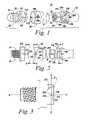
- FIG. 1is an exploded isometric view of a connector system according to an illustrative embodiment of the invention with first and second connector bodies and a collar;
- FIG. 2is an exploded side view, of the first body, collar and second body of the connector system according to an illustrative embodiment of the invention
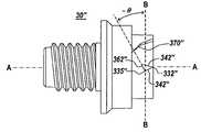
- FIG. 3is an enlarged view of the second body, illustrating in detail the configuration of the camming tab.
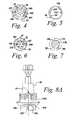
- FIG. 4is an end elevation view of the first body viewed from a plane X—X between the collar and second body.
- FIG. 5is an end elevation view of the collar viewed from a plane X—X between the collar and second body.
- FIG. 6is an end elevation view of the second body viewed from a plane X—X between the collar and second body;
- FIG. 7illustrates a section on line 7 — 7 of FIG. 2 of the connector system.
- FIGS. 8 a and 8 billustrate the second connector body according to an alternate embodiment of the invention.
- FIG. 9illustrates an alternate embodiment of the second body, wherein the camming tab is angled in a opposite direction to the camming tab of FIG. 3 to increase the breakaway force.
- the present inventionprovides a self-latching connector system including one or more components configured to control the breakaway force of the connector system.
- the inventionwill be described below relative to illustrative embodiments. Those skilled in the art will appreciate that the present invention may be implemented in a number of different applications and embodiments and is not specifically limited in its application to the particular embodiments depicted herein.
- FIG. 1illustrates a locking connector 10 according to an illustrative embodiment of the invention.
- the connector 10is used in an electrical application, though one skilled in the art will recognize that the connector can be implemented in any suitable system.
- the connector 10comprises a first connector body or plug 20 and a second connector body or receptacle 30 configured to receive and/or engage the first connector body 20 .
- the first connector body 20is a male connector having a cylindrical shaped housing with male contacts 22 enclosed in recesses 23 of an insulative boss 24 .
- the illustrative second connector body 30is a female connector having a cylindrical shaped housing defining a cavity 34 for receiving the boss 26 .
- the second bodyfurther includes female contacts 32 disposed in the cavity 34 for mating with the male contacts 22 of the first connector 20 .
- the plug boss 24telescopes into the cavity 34 of the second connector body or receptacle 30 , such that the male contacts 22 axially mate with the female contacts 32 when the first body 20 engages the second body 30 along the longitudinal axis A—A.
- the second bodymay further include a flange 29 and threads 31 for mounting the second body in a panel with a nut or other suitable mating device.
- annular collar 40is rotatably mounted on the first connector body 10 to latch the connector bodies 20 , 30 together. When the two bodies are mated, the annular collar 40 encircles the boss 24 of the first body and the socket 34 of the second body to hold the connector bodies together.
- the collar 40includes one or more internal radial stops 42 and the first connector body includes a first flange 110 having one or more passageways 120 extending longitudinally and configured to receive the stops 42 on the collar 40 .
- An annular groove 130is also formed on the first connector body 20 for receiving the internal radial stops 42 of the collar.
- the collar 40is mounted to the first body 20 by sliding the collar 40 along the longitudinal axis A—A over the boss 24 , such that the internal radial stops 42 on the collar 40 are admitted through the passageways 120 on the first body and into the annular groove 130 .
- the annular groove 130axially confines the stops and holds the collar 40 rotatively around the first body 10 .
- the stopslimit the amount of rotation of the collar to a range of about forty degrees.
- suitable means of rotatably locking the annular collar 40 to the first connector body 20may be used in accordance with the teachings of the invention.
- the collarfurther includes at least one camming tab 210 configured to engage one or more camming tabs 220 on the second body to lock the connector bodies together.
- the camming tabs 210 , 220comprise opposing, pie-shaped protrusions, though other configurations may be used according to the present invention.
- the camming tabs 210 , 220comprise opposing points 331 , 332 , respectively, and two camming surfaces 341 , 342 , respectively, flaring away from each point to intersection with a back surface 361 , 362 , respectively.
- one or more of the back surfaces 361 , 362is angled relative to a radial axis B—B that extends along the direction of rotation of the collar and perpendicular to the longitudinal axis A—A, as shown in detail in FIG. 3 to facilitate automatic release of the connector bodies when a predetermined force is applied to the connector system.
- the angled back surface 362 of the receptacle tabcontrasts the camming tabs described in U.S. Pat. Nos. 5,067,909, 5,167,522 and 5,662,488, which extend in the direction of rotation of the collar, perpendicular to the longitudinal axis A—A.
- the back surface 362is inclined from the radial axis B—B to form a ramp that extends at a forward angle, i.e., in a direction that is axially and radially forward relative to a back point 335 of the camming tab 220 .
- radiallyrefers to the direction of rotation of the collar, axis B—B, and “axially” refers to the direction of the axis A—A, i.e. along the longitudinal axis of the connector system.
- “Radially forward”refers to the direction of rotation of the collar indicated by the marker 300 on the collar, i.e., toward the ramp 370 from the tab 220 .
- the back surface of the receptacle camming tabextends at an angle ⁇ , relative to the line B—B, as shown in FIG. 3 , and relative to the back surface of the camming tabs described in U.S. Pat. No. 5,067,909. In the embodiment shown in FIG. 3 , the angle ⁇ extends between about 5 degrees and about 45 degrees in the axially forward direction. The operation of the camming tabs will be described in detail below.
- a coiled spring 47may be provided for biasing the collar 40 into a normal position when the collar is mounted on the first connector body 20 .
- the coiled spring 47illustrated as a round wire of spring metal, though any suitable mechanism for biasing the collar may be used, is also confined in the annular groove 130 of the first body 20 .
- the spring 47may be anchored at a first end inside the collar at a first stop 142 (shown in FIG. 5 ) and at a second end in a small recess 138 in the groove 130 . As shown in FIG. 6 , the spring 47 is biased yieldingly to constantly urge the collar stops 42 to a normal position abutting the opposed stops 190 in the groove 130 .
- the camming tabs 210 provided on the collar 40are located relative to the male contacts 22 of the first body such that the collar camming tabs 210 and male contacts 22 are in matching alignment with corresponding camming tabs 220 on the second body 20 and the female contacts 32 on the second body 20 , respectively.
- the insulative boss 24 of the first connector body 10further includes longitudinal keyways 260 and 270 , which receive keys 230 and 240 formed on an inner surface of the receptacle cavity on the corresponding female connector to assure correct angular alignment during mating engagement.
- the keysmay comprise a relatively narrow key 230 and a relatively wide key 240 and the keyways may comprise a relatively narrow keyway 260 for receiving the narrow key 230 and a relatively wide keyway 270 for receiving the wide key 240 .
- the keys and keywaysare arranged such that when the first connector body 20 and the second connector body 30 are engaged (i.e. the keys are inserted in the corresponding keyways), the collar camming tabs 210 have substantially the same angular relationship to the male contacts as the receptacle camming tabs have to the female contacts when the collar is in the rest position.
- Index marksmay also be provided as a visual aid to the correct angular alignment in alignment of the bodies 20 , 30 .
- the illustrative connector systemincludes a first index mark 290 on the collar, a second index mark 280 on the first body and a third index mark 310 on the second body, which align when the connector bodies are properly engaged.
- the mark 290 on the collarmay further include an arrowhead 300 indicating the direction in which the collar 40 can be rotated from the normal position during the two operations of locking engagement and disengagement of the two bodies.
- the markers 290 , 310 on the collar 40 and the female connector 30are manually aligned and the two bodies are pushed together along the longitudinal axis A—A to achieve a snap-lock.
- the second body 30receives the first body 10 , as the boss 24 telescopes in the cavity 34 and the keys 230 , 240 slide into the keyways 260 , 270 , respectively.
- the camming tabs 210 , 220slide past each other.
- the collar camming tab 210is offset a small angle from a central plane through the collar and receptacle to facilitate engagement.
- the mutual edging action of the camming surfaces 341 , 342forces the collar 40 to rotate against the spring, i.e., in the radially backward direction, allowing the collar tab 210 to slide around the receptacle tab 220 and then spring back with its back surface 361 behind the back surface 362 of the receptacle tab 220 .
- the tabslock the first body 20 to the second body 30 through a predetermined range of forces.
- the spring 47reverses rotation of the collar 40 until the faces of the collar stops strike the opposed faces of the plug stops.
- An audible “snap”signals that the first body 20 , the plug, and the second body 30 , the receptacle, are locked together. Locking may be visually confirmed by alignment of the index marks after the automatic return of the collar to its normal position by the spring.
- the camming tabs 210 , 220are configured to provide automatic release when a predetermined force is applied to one or both of the bodies.
- the connectorsmay be released manually, by rotating the collar 40 in the radially forward direction, or by applying a predetermined breakaway force to the connectors along the longitudinal axis A—A.
- the collar 40is manually rotated in the radially forward direction, as indicated by the arrowhead 300 .
- the rotation of the collar 40 in the radially forward directionturns the collar camming tabs 210 towards a circumferential ramp 370 slanting across the paths of the tabs.
- the camming face of each rampis angled away from the adjacent tab, so that it cams the collar tab 210 , collar 40 and first body 20 apart and out of engagement with the second body 30 . In this manner, disengagement can be effected without pulling and straining the cord extending from the plug, because the rotation of the collar is in a plane at right angles to the axis of the plug and cord.
- the camming tabsare also configured to automatically disengage upon application of a predetermined breakaway force to either of the connector bodies.
- the back surface 362 of the receptacle camming tabis angled relative to the direction of rotation of the collar 40 to provide automatic release upon application of a force along the longitudinal axis A—A that exceeds a predetermined value.
- the predetermined breakaway forceis inversely proportional to the angle of the back surface of the receptacle camming tab relative to the line B—B.
- the back surface 362 of the receptacle camming tab 220is angled about 10 degrees, as shown in FIG.
- the predetermined breakaway forceis between about one pound and about twenty pounds and preferably about ten pounds for the illustrated angle ⁇ .
- the sloping back surfaceallows the collar camming tab 210 to slide past the receptacle camming tab 220 , releasing the connection without damaging the connector components and/or before damage to equipment or persons occurs.
- the camming tabs described in the prior arthave back surfaces which are substantially perpendicular to the longitudinal direction along axis A—A, which prevent the tabs from sliding past each other when a pulling force is applied along the longitudinal axis.
- a receptacle body 30 ′ of the locking connector pairincludes engagement recesses 300 formed in the exterior of a cavity 34 ′, as shown in FIGS. 8 a and 8 b , in place of the camming tab and circumferential ramp.
- the engagement recesses 300are configured to engage with the collar camming tabs 210 to temporarily lock the collar to the second body.
- Each engagement recess 300includes a ramped wall 370 ′ corresponding to the circumferential ramp 370 of the receptacle 30 of FIGS. 1–9 , a longitudinal wall 380 and a protrusion 220 ′ forming a camming tab extending from the longitudinal wall 380 .
- the protrusionincludes a back wall 210 a extending axially and radially forward from the longitudinal wall 380 at a predetermined angle relative to the line B—B and a camming wall 210 b forming a camming surface for allowing the collar tab to slide past the protrusion 220 ′ when slid along the longitudinal axis.
- the longitudinal wall 380 and the protrusionform a recess slot located axially behind the protrusion 220 ′ for retaining the collar camming tab when the receptacle body 30 ′ is engaged with the first plug body 20 .
- the back wall 210 ais angled by a selected amount to provide automatic release of the collar camming tab when a predetermined force is applied to the connector bodies.
- the connectormay be configured to increase the breakaway force between the first and second connector bodies, thereby reinforcing the connection between the first and second connector bodies.
- one or more of the back surfaces 361 ′′, 362 ′′, preferably the back surface 362 ′′ on the camming tab 220 ′′ of the second connector 30 ′′is angled relative to a radial axis B—B that extends along the direction of rotation of the collar and to the longitudinal axis A—A, as shown in detail in FIG. 9 , to increase the breakaway force the first and second connector.
- the angled back surface 362 ′′ of the receptacle tabextends in an inverse direction relative to the back surface 362 of the receptacle tab 220 of FIG. 3 .
- the back surface 362 ′′ of the reinforcing tab 220 ′′is inclined from the radial axis B—B to form a ramp that extends at a negative angle ⁇ , i.e., in a direction that is axially backward and radially forward from a back point 335 ′′ of the camming tab 220 ′′.
- the back surface 362 ′′ of the receptacle camming tabextends at an angle ⁇ to reinforce the connection between the bodies by urging an engaged collar camming tab 210 in the radially backward direction, away from the ramp 370 .
- the configuration of the back surface 362 ′′thus inhibits sliding of the collar tab 210 toward the ramp, thereby preventing release of the collar tab 210 from the camming tab 220 ′′ of the second connector 30 ′′.
- the angle ⁇is between about 5 degrees and about 45 degrees relative to the line B—B, as shown in FIG. 3 , and relative to the back surface of the camming tabs described in U.S. Pat. No. 5,067,909.
- the connectormay have any suitable configuration for modifying the breakaway force between the first body and the second body.
- the reinforced locking connector second connector body 30 ′′may alternatively include an engagement recess, corresponding to the engagement recess 300 shown in FIGS. 8A and 8B , including a protrusion, corresponding to the protrusion 220 ′, having a back wall extending at a negative angle from a longitudinal wall. The reverse orientation of the back wall serves to prevent premature release of the connector bodies.
- the back wall of a camming tab of a locking connectormay extend at a forward angle relative to the radial axis B—B to decrease the breakaway force and allow for quick release of the connector bodies.
- the back wallmay extend at a negative angle relative to the radial axis B—B to increase the breakaway force and prevent release of the connector bodies.
- the correlation between the angle of the back wall and the breakaway forcedepends on the type of material and properties of the material used to form the connector bodies. For example, for materials having a higher coefficient of friction, a relatively larger angle may correspond to a selected breakaway force, while materials having a lower coefficient of friction require a relatively smaller angle to obtain the selected breakaway force.
- the angle of the back wall of the receptacle camming tabis between about 5 and about 45 degrees relative to the radial axis B—B, in either direction, and the predetermined breakaway force is between about one and about forty pounds, depending on the configuration of the back surface of the camming tab, though one skilled in the art will recognize any suitable angle and breakaway force may be used in accordance with the present invention.
- One of ordinary skill in the artwill be able to determine a suitable angle to provide a desired breakaway force in a connector system of the invention.
- the collarmay alternatively be mounted on the female connector and camming tabs may be provided on the male connector.
- the rotating collar and camming tabs of the connectorprovide automatic locking engagement of the plug and socket without deformation of the plastic, insulative connector bodies or collar. Engagement is indicated positively by an audible snap and by alignment of index marks.
- the springallows a rotary disengaging manipulation, which is convenient and which places no longitudinal strain on a cord or cable connected to the plug body.
- the connectorsprovide a secure connection up until a predetermined breakaway force and further allow automatic de-coupling of the connector system to prevent injury, damage to the connector bodies, damage to the cords attached to the connector bodies and/or damage to components attached to the connector bodies.
- the connector paircan be reused even after the bodies have been separated by the application of the predetermined force.
- the breakaway forcecan be modified by changing the angle of the back wall of the receptacle camming tab.
- a receptacle body having a modified camming tab to allow for the automatic de-couplingcan be used with current plug bodies, such as the male connector of the PULSE-LOK from Alden Products, described in U.S. Pat. No. 5,067,909 without requiring modification of the plug body. In this manner, a connector system can be easily converted to provide automatic de-coupling at a predetermined without requiring replacement of all of the components of the system.
Landscapes
- Details Of Connecting Devices For Male And Female Coupling (AREA)
Abstract
Description
Claims (18)
Priority Applications (1)
| Application Number | Priority Date | Filing Date | Title |
|---|---|---|---|
| US10/763,279US7086886B2 (en) | 2002-07-23 | 2004-01-23 | Reinforced locking connector |
Applications Claiming Priority (2)
| Application Number | Priority Date | Filing Date | Title |
|---|---|---|---|
| US10/202,514US6776638B2 (en) | 2002-07-23 | 2002-07-23 | Breakaway locking connector |
| US10/763,279US7086886B2 (en) | 2002-07-23 | 2004-01-23 | Reinforced locking connector |
Related Parent Applications (1)
| Application Number | Title | Priority Date | Filing Date |
|---|---|---|---|
| US10/202,514Continuation-In-PartUS6776638B2 (en) | 2002-07-23 | 2002-07-23 | Breakaway locking connector |
Publications (2)
| Publication Number | Publication Date |
|---|---|
| US20050059284A1 US20050059284A1 (en) | 2005-03-17 |
| US7086886B2true US7086886B2 (en) | 2006-08-08 |
Family
ID=46301802
Family Applications (1)
| Application Number | Title | Priority Date | Filing Date |
|---|---|---|---|
| US10/763,279Expired - LifetimeUS7086886B2 (en) | 2002-07-23 | 2004-01-23 | Reinforced locking connector |
Country Status (1)
| Country | Link |
|---|---|
| US (1) | US7086886B2 (en) |
Cited By (9)
| Publication number | Priority date | Publication date | Assignee | Title |
|---|---|---|---|---|
| US20100112854A1 (en)* | 2008-10-13 | 2010-05-06 | Radiall | Easily-gripped coaxial connector element |
| US8250763B2 (en) | 2005-04-27 | 2012-08-28 | The Gillette Company | Battery-operated razor |
| US20150177467A1 (en)* | 2013-12-20 | 2015-06-25 | Senko Advanced Components, Inc. | Lockable connectors and connection assemblies |
| US20150202016A1 (en)* | 2012-08-31 | 2015-07-23 | Sanofi-Aventis Deutschland Gmbh | Impact-Resistant Fastening Assembly for a Medical Device |
| CN104868284A (en)* | 2015-06-05 | 2015-08-26 | 李广连 | Butting-type electric connector for electric torch |
| US9136643B2 (en) | 2014-02-04 | 2015-09-15 | Dg Interconnects | Connector device |
| US9502824B2 (en) | 2014-05-23 | 2016-11-22 | Itt Manufacturing Enterprises, Llc | Electrical connector |
| US11081838B2 (en)* | 2017-08-08 | 2021-08-03 | Phoenix Contact Gmbh & Co. Kg | Electrical connector part having a locking element |
| DE102021107137A1 (en) | 2021-03-23 | 2022-09-29 | Kunshan Outdoor Solutions Electronics Co., Ltd. | Electrical terminal connector and electrical connector assembly therefor |
Families Citing this family (5)
| Publication number | Priority date | Publication date | Assignee | Title |
|---|---|---|---|---|
| US8708211B2 (en) | 2009-02-12 | 2014-04-29 | Covidien Lp | Powered surgical instrument with secondary circuit board |
| CN103618168B (en)* | 2013-11-22 | 2016-01-06 | 苏州华旃航天电器有限公司 | A kind of Bidirectional unlocking cylindrical connector plug and socket thereof |
| US9595788B1 (en)* | 2016-04-25 | 2017-03-14 | Te Connectivity Corporation | Electrical connector having a flexible latch actuated by a ramp on a release collar |
| DE102017104123B3 (en)* | 2017-02-28 | 2018-04-26 | Harting Electric Gmbh & Co. Kg | Protective separation device for a rectangular connector |
| US12085210B2 (en)* | 2020-01-17 | 2024-09-10 | Sierra Nevada Company, Llc | Aircraft tail lock |
Citations (35)
| Publication number | Priority date | Publication date | Assignee | Title |
|---|---|---|---|---|
| US3719918A (en) | 1971-11-04 | 1973-03-06 | Schlumberger Technology Corp | Electrical connector |
| US3901574A (en)* | 1971-12-30 | 1975-08-26 | Amp Inc | Electrical connector |
| US3953099A (en)* | 1973-12-10 | 1976-04-27 | Bunker Ramo Corporation | One-piece environmental removable contact connector |
| US4070080A (en) | 1976-12-27 | 1978-01-24 | Viking Industries, Inc. | Circular connectors |
| US4142769A (en) | 1977-12-09 | 1979-03-06 | Alden Research Foundation | Electrical connector |
| US4146288A (en) | 1977-11-11 | 1979-03-27 | International Standard Electric Corporation | Bayonet connector coupling arrangement |
| US4148542A (en) | 1977-10-31 | 1979-04-10 | Alden Research Foundation | Panel mounted locking device for components |
| US4154498A (en) | 1977-10-31 | 1979-05-15 | Alden Research Foundation | Removable electrical connector |
| US4235832A (en) | 1978-07-31 | 1980-11-25 | Alden Research Foundation | Molding method |
| US4239315A (en)* | 1978-12-18 | 1980-12-16 | International Telephone And Telegraph Corporation | Electrical connector |
| US4243291A (en) | 1978-11-03 | 1981-01-06 | Alden Research Foundation | Polarized electrical outlet |
| US4310213A (en)* | 1978-04-05 | 1982-01-12 | Amp Incorporated | Electrical connector kit |
| US4339407A (en) | 1980-10-02 | 1982-07-13 | Alden Research Foundation | Electronic circuit encapsulation |
| US4359255A (en) | 1980-11-14 | 1982-11-16 | The Bendix Corporation | Coupling ring having detent means |
| US4481380A (en) | 1982-08-26 | 1984-11-06 | Alden Research Foundation | High voltage insulator for electrical components having telescoping insulative sleeves |
| US4497530A (en)* | 1983-07-25 | 1985-02-05 | Amp Incorporated | Electrical connector having a coupling indicator |
| US4536048A (en)* | 1983-05-11 | 1985-08-20 | Allied Corporation | Anti-decoupling mechanism for an electrical connector assembly |
| US4552427A (en)* | 1982-12-13 | 1985-11-12 | International Telephone & Telegraph Corp. | Self-locking connector |
| US4568139A (en) | 1984-12-10 | 1986-02-04 | Alden Research Foundation | Laterally engaged electrical connector |
| US4568795A (en) | 1983-08-19 | 1986-02-04 | Alden Research Foundation | Insulation filled carrier of conductive components |
| US4582388A (en) | 1983-04-18 | 1986-04-15 | Alden Research Foundation | High voltage snap on coupling |
| US4588245A (en) | 1984-08-23 | 1986-05-13 | Flight Connector Corporation | Self-locking coupling nut |
| US4684189A (en) | 1985-08-22 | 1987-08-04 | Alden Research Foundation | High voltage plug and receptacle |
| US4720764A (en) | 1987-03-02 | 1988-01-19 | Alden Research Foundation | Operator static grounding cord |
| US4773871A (en) | 1987-06-29 | 1988-09-27 | Alden Research Foundation | High voltage bulkhead coupling |
| US4820185A (en) | 1988-01-20 | 1989-04-11 | Hughes Aircraft Company | Anti-backlash automatic locking connector coupling mechanism |
| US5067909A (en) | 1991-02-25 | 1991-11-26 | Alden Products Company | Locking multiple conductor electrical connector |
| US5167522A (en) | 1991-02-25 | 1992-12-01 | Alden Products Company | Locking multiple conductor electrical connector |
| US5211587A (en) | 1992-08-20 | 1993-05-18 | Alden Proucts Company | High voltage connector with corona shield |
| US5662488A (en) | 1996-10-31 | 1997-09-02 | Alden; Peter H. | Quick connect coupling system for rapidly joining connectors and/or other elongated bodies |
| US5707252A (en) | 1995-10-10 | 1998-01-13 | Alden Products Company | Snap-together x-ray cable coupling nut assembly |
| US5816835A (en) | 1996-10-21 | 1998-10-06 | Alden Products Company | Multi-sleeve high-voltage cable plug with vented seal |
| US6010348A (en) | 1997-05-20 | 2000-01-04 | Alden Products Company | Field-assembled two-piece snap-fit self-sealed electrical connector |
| US6162082A (en)* | 1999-01-28 | 2000-12-19 | Badger Meter, Inc. | Submersible electrical connector and method for quick connection and disconnection including tamper indication |
| US6226068B1 (en) | 1999-08-27 | 2001-05-01 | Amphenol Corporation | Self-locking bayonet coupling mechanism |
- 2004
- 2004-01-23USUS10/763,279patent/US7086886B2/ennot_activeExpired - Lifetime
Patent Citations (35)
| Publication number | Priority date | Publication date | Assignee | Title |
|---|---|---|---|---|
| US3719918A (en) | 1971-11-04 | 1973-03-06 | Schlumberger Technology Corp | Electrical connector |
| US3901574A (en)* | 1971-12-30 | 1975-08-26 | Amp Inc | Electrical connector |
| US3953099A (en)* | 1973-12-10 | 1976-04-27 | Bunker Ramo Corporation | One-piece environmental removable contact connector |
| US4070080A (en) | 1976-12-27 | 1978-01-24 | Viking Industries, Inc. | Circular connectors |
| US4148542A (en) | 1977-10-31 | 1979-04-10 | Alden Research Foundation | Panel mounted locking device for components |
| US4154498A (en) | 1977-10-31 | 1979-05-15 | Alden Research Foundation | Removable electrical connector |
| US4146288A (en) | 1977-11-11 | 1979-03-27 | International Standard Electric Corporation | Bayonet connector coupling arrangement |
| US4142769A (en) | 1977-12-09 | 1979-03-06 | Alden Research Foundation | Electrical connector |
| US4310213A (en)* | 1978-04-05 | 1982-01-12 | Amp Incorporated | Electrical connector kit |
| US4235832A (en) | 1978-07-31 | 1980-11-25 | Alden Research Foundation | Molding method |
| US4243291A (en) | 1978-11-03 | 1981-01-06 | Alden Research Foundation | Polarized electrical outlet |
| US4239315A (en)* | 1978-12-18 | 1980-12-16 | International Telephone And Telegraph Corporation | Electrical connector |
| US4339407A (en) | 1980-10-02 | 1982-07-13 | Alden Research Foundation | Electronic circuit encapsulation |
| US4359255A (en) | 1980-11-14 | 1982-11-16 | The Bendix Corporation | Coupling ring having detent means |
| US4481380A (en) | 1982-08-26 | 1984-11-06 | Alden Research Foundation | High voltage insulator for electrical components having telescoping insulative sleeves |
| US4552427A (en)* | 1982-12-13 | 1985-11-12 | International Telephone & Telegraph Corp. | Self-locking connector |
| US4582388A (en) | 1983-04-18 | 1986-04-15 | Alden Research Foundation | High voltage snap on coupling |
| US4536048A (en)* | 1983-05-11 | 1985-08-20 | Allied Corporation | Anti-decoupling mechanism for an electrical connector assembly |
| US4497530A (en)* | 1983-07-25 | 1985-02-05 | Amp Incorporated | Electrical connector having a coupling indicator |
| US4568795A (en) | 1983-08-19 | 1986-02-04 | Alden Research Foundation | Insulation filled carrier of conductive components |
| US4588245A (en) | 1984-08-23 | 1986-05-13 | Flight Connector Corporation | Self-locking coupling nut |
| US4568139A (en) | 1984-12-10 | 1986-02-04 | Alden Research Foundation | Laterally engaged electrical connector |
| US4684189A (en) | 1985-08-22 | 1987-08-04 | Alden Research Foundation | High voltage plug and receptacle |
| US4720764A (en) | 1987-03-02 | 1988-01-19 | Alden Research Foundation | Operator static grounding cord |
| US4773871A (en) | 1987-06-29 | 1988-09-27 | Alden Research Foundation | High voltage bulkhead coupling |
| US4820185A (en) | 1988-01-20 | 1989-04-11 | Hughes Aircraft Company | Anti-backlash automatic locking connector coupling mechanism |
| US5067909A (en) | 1991-02-25 | 1991-11-26 | Alden Products Company | Locking multiple conductor electrical connector |
| US5167522A (en) | 1991-02-25 | 1992-12-01 | Alden Products Company | Locking multiple conductor electrical connector |
| US5211587A (en) | 1992-08-20 | 1993-05-18 | Alden Proucts Company | High voltage connector with corona shield |
| US5707252A (en) | 1995-10-10 | 1998-01-13 | Alden Products Company | Snap-together x-ray cable coupling nut assembly |
| US5816835A (en) | 1996-10-21 | 1998-10-06 | Alden Products Company | Multi-sleeve high-voltage cable plug with vented seal |
| US5662488A (en) | 1996-10-31 | 1997-09-02 | Alden; Peter H. | Quick connect coupling system for rapidly joining connectors and/or other elongated bodies |
| US6010348A (en) | 1997-05-20 | 2000-01-04 | Alden Products Company | Field-assembled two-piece snap-fit self-sealed electrical connector |
| US6162082A (en)* | 1999-01-28 | 2000-12-19 | Badger Meter, Inc. | Submersible electrical connector and method for quick connection and disconnection including tamper indication |
| US6226068B1 (en) | 1999-08-27 | 2001-05-01 | Amphenol Corporation | Self-locking bayonet coupling mechanism |
Cited By (13)
| Publication number | Priority date | Publication date | Assignee | Title |
|---|---|---|---|---|
| US8250763B2 (en) | 2005-04-27 | 2012-08-28 | The Gillette Company | Battery-operated razor |
| US20100112854A1 (en)* | 2008-10-13 | 2010-05-06 | Radiall | Easily-gripped coaxial connector element |
| US20150202016A1 (en)* | 2012-08-31 | 2015-07-23 | Sanofi-Aventis Deutschland Gmbh | Impact-Resistant Fastening Assembly for a Medical Device |
| US9477049B2 (en)* | 2013-12-20 | 2016-10-25 | Senko Advanced Components, Inc. | Lockable connectors and connection assemblies |
| US20150177467A1 (en)* | 2013-12-20 | 2015-06-25 | Senko Advanced Components, Inc. | Lockable connectors and connection assemblies |
| US20170031108A1 (en)* | 2013-12-20 | 2017-02-02 | Senko Advanced Components, Inc. | Lockable Connectors and Connection Assemblies |
| US9810858B2 (en)* | 2013-12-20 | 2017-11-07 | Senko Advanced Components, Inc. | Lockable connectors and connection assemblies |
| US9136643B2 (en) | 2014-02-04 | 2015-09-15 | Dg Interconnects | Connector device |
| US9502824B2 (en) | 2014-05-23 | 2016-11-22 | Itt Manufacturing Enterprises, Llc | Electrical connector |
| CN104868284A (en)* | 2015-06-05 | 2015-08-26 | 李广连 | Butting-type electric connector for electric torch |
| US11081838B2 (en)* | 2017-08-08 | 2021-08-03 | Phoenix Contact Gmbh & Co. Kg | Electrical connector part having a locking element |
| DE102021107137A1 (en) | 2021-03-23 | 2022-09-29 | Kunshan Outdoor Solutions Electronics Co., Ltd. | Electrical terminal connector and electrical connector assembly therefor |
| DE102021107137B4 (en) | 2021-03-23 | 2022-10-06 | Kunshan Outdoor Solutions Electronics Co., Ltd. | Electrical terminal connector and electrical connector assembly therefor |
Also Published As
| Publication number | Publication date |
|---|---|
| US20050059284A1 (en) | 2005-03-17 |
Similar Documents
| Publication | Publication Date | Title |
|---|---|---|
| US6776638B2 (en) | Breakaway locking connector | |
| US5067909A (en) | Locking multiple conductor electrical connector | |
| US5167522A (en) | Locking multiple conductor electrical connector | |
| US7086886B2 (en) | Reinforced locking connector | |
| EP2950401B1 (en) | Electrical connector | |
| EP3084232B1 (en) | Lockable connector | |
| US9136643B2 (en) | Connector device | |
| US8591249B2 (en) | Flexible breakaway connector | |
| US6234826B1 (en) | Connector position assurance device | |
| US6267612B1 (en) | Adaptive coupling mechanism | |
| EP1666783B1 (en) | Pipe joint and socket for pipe joint | |
| US20140227900A1 (en) | Connector having coupling mechanism | |
| EP2889524A2 (en) | Latching mechanism for clamshell type couplers | |
| US10355406B2 (en) | Electrical connector | |
| JPS6134038B2 (en) | ||
| GB1595968A (en) | Electrical connector with arcuate detent means | |
| WO2019104010A1 (en) | Coaxial connector | |
| US11355880B2 (en) | Coaxial connector with axially-floating inner contact | |
| US4531801A (en) | Plug and receptacle connector locking means | |
| US9203180B2 (en) | Connector having coupling mechanism | |
| US20070281552A1 (en) | An electrical connector with an anti-splay ferrule | |
| EP1368865B1 (en) | Connector | |
| US8079868B2 (en) | Electrical connector with releasable locking clip | |
| US6666726B2 (en) | Electrical connector assembly | |
| EP1085615B1 (en) | Connector system |
Legal Events
| Date | Code | Title | Description |
|---|---|---|---|
| AS | Assignment | Owner name:ALDEN PRODUCTS COMPANY, MASSACHUSETTS Free format text:ASSIGNMENT OF ASSIGNORS INTEREST;ASSIGNOR:THURSTON, BRYAN A.;REEL/FRAME:015408/0435 Effective date:20041122 | |
| STCF | Information on status: patent grant | Free format text:PATENTED CASE | |
| FPAY | Fee payment | Year of fee payment:4 | |
| FEPP | Fee payment procedure | Free format text:PAT HOLDER NO LONGER CLAIMS SMALL ENTITY STATUS, ENTITY STATUS SET TO UNDISCOUNTED (ORIGINAL EVENT CODE: STOL); ENTITY STATUS OF PATENT OWNER: LARGE ENTITY | |
| FEPP | Fee payment procedure | Free format text:PAYER NUMBER DE-ASSIGNED (ORIGINAL EVENT CODE: RMPN); ENTITY STATUS OF PATENT OWNER: LARGE ENTITY Free format text:PAYOR NUMBER ASSIGNED (ORIGINAL EVENT CODE: ASPN); ENTITY STATUS OF PATENT OWNER: LARGE ENTITY | |
| FPAY | Fee payment | Year of fee payment:8 | |
| MAFP | Maintenance fee payment | Free format text:PAYMENT OF MAINTENANCE FEE, 12TH YEAR, LARGE ENTITY (ORIGINAL EVENT CODE: M1553) Year of fee payment:12 | |
| AS | Assignment | Owner name:AMPHENOL ALDEN PRODUCTS COMPANY, MASSACHUSETTS Free format text:MERGER;ASSIGNOR:ALDEN PRODUCTS CO.;REEL/FRAME:045062/0311 Effective date:20060328 |