US7086839B2 - Micro-fabricated electrokinetic pump with on-frit electrode - Google Patents
Micro-fabricated electrokinetic pump with on-frit electrodeDownload PDFInfo
- Publication number
- US7086839B2 US7086839B2US10/669,495US66949503AUS7086839B2US 7086839 B2US7086839 B2US 7086839B2US 66949503 AUS66949503 AUS 66949503AUS 7086839 B2US7086839 B2US 7086839B2
- Authority
- US
- United States
- Prior art keywords
- layer
- porous structure
- electrically conductive
- electroosmotic
- porous material
- Prior art date
- Legal status (The legal status is an assumption and is not a legal conclusion. Google has not performed a legal analysis and makes no representation as to the accuracy of the status listed.)
- Expired - Lifetime, expires
Links
Images


Classifications
- F—MECHANICAL ENGINEERING; LIGHTING; HEATING; WEAPONS; BLASTING
- F04—POSITIVE - DISPLACEMENT MACHINES FOR LIQUIDS; PUMPS FOR LIQUIDS OR ELASTIC FLUIDS
- F04B—POSITIVE-DISPLACEMENT MACHINES FOR LIQUIDS; PUMPS
- F04B19/00—Machines or pumps having pertinent characteristics not provided for in, or of interest apart from, groups F04B1/00 - F04B17/00
- F04B19/006—Micropumps
- F—MECHANICAL ENGINEERING; LIGHTING; HEATING; WEAPONS; BLASTING
- F04—POSITIVE - DISPLACEMENT MACHINES FOR LIQUIDS; PUMPS FOR LIQUIDS OR ELASTIC FLUIDS
- F04B—POSITIVE-DISPLACEMENT MACHINES FOR LIQUIDS; PUMPS
- F04B17/00—Pumps characterised by combination with, or adaptation to, specific driving engines or motors
- F—MECHANICAL ENGINEERING; LIGHTING; HEATING; WEAPONS; BLASTING
- F28—HEAT EXCHANGE IN GENERAL
- F28D—HEAT-EXCHANGE APPARATUS, NOT PROVIDED FOR IN ANOTHER SUBCLASS, IN WHICH THE HEAT-EXCHANGE MEDIA DO NOT COME INTO DIRECT CONTACT
- F28D15/00—Heat-exchange apparatus with the intermediate heat-transfer medium in closed tubes passing into or through the conduit walls ; Heat-exchange apparatus employing intermediate heat-transfer medium or bodies
- F—MECHANICAL ENGINEERING; LIGHTING; HEATING; WEAPONS; BLASTING
- F28—HEAT EXCHANGE IN GENERAL
- F28F—DETAILS OF HEAT-EXCHANGE AND HEAT-TRANSFER APPARATUS, OF GENERAL APPLICATION
- F28F2250/00—Arrangements for modifying the flow of the heat exchange media, e.g. flow guiding means; Particular flow patterns
- F28F2250/08—Fluid driving means, e.g. pumps, fans
Definitions
- the present inventionrelates to an apparatus for cooling and a method thereof.
- the present inventionis directed to a frit based pump or electroosmotic pump with on-frit electrode and method of manufacturing thereof.
- the position as well as the distance of the electrodes in relation to the porous structureis very important. Inconsistency in the distances between electrodes on each side of the porous structure pump result in variations in the electric field across the porous structure. These variations in the electric field affect the flow rate of the fluid through the pump and cause the pump to operate inefficiently.
- the electrodes 12 , 14are spaced apart periodically along the top and bottom surface 18 , 20 of the pump.
- Voltage provided to the electrodes 12 , 14 from a power source (not shown)creates an electric field across the pump 10 , whereby the electrical field generated by the electrodes 12 , 14 forces the fluid to travel through the channels from the bottom side to the top side.
- variations in the electric fieldcauses the porous structure to pump more fluid in areas where there is a stronger electric field and pump less fluid through areas where the electric field is weaker.
- Periodically spaced electrodes 12 , 14 along the surfaces 18 , 20 of the pump 10can create a non-uniform electric field across the porous structure 10 .
- cathodes 12 A– 12 Fare placed apart from one another on the top surface 18 of the pump 10
- anodes 14 B– 14 Fare placed apart from one another on the bottom surface of the pump 10 .
- the anode 14 Bis directly below the cathode 12 B, but not directly below the cathode 12 A.
- an electric fieldis generated between the electrodes 12 A and 14 B as well as the electrodes 12 B and 14 B.
- the electric field in between a pair of electrodesbecomes greater as the distance between the pair of electrodes becomes smaller.
- the electrical fieldis dependent on the distance between electrodes 12 , 14 .
- the distance between electrodes 12 A and 14 Bis greater than the distance between electrodes 12 B and 14 B. Therefore, the electrical field between the electrodes 12 A and 14 B is weaker than the electrical field between the electrodes 12 B and 14 B. Since, the variation in the electrical field across the porous structure 10 causes inconsistencies in the amount of fluid pumped through different areas of the pump 10 more fluid will be pumped through the areas of the pump 10 where the electrical field is greater than the areas in the pump 10 where the electrical field is weaker.
- electrodes 12 E and 14 Care located directly across the pump 10 from one another and have a high electrical field therebetween.
- the electrode 12 Dis located proximal to, but not directly above, the anode 14 C, whereby current passes between anode 14 C and cathode 12 D and the voltage generates an electrical field therebetween.
- the absence or lack of electrical field between the electrodes 12 D and 14 Eleaves the areas between electrodes 12 D and 14 E of the pump 10 with less current passing therethrough. As a result, less fluid is pumped through the portion between electrodes 12 D and 12 E in the pump 10 .
- an electroosmotic pumpcomprises at least one porous structure which pumps fluid therethrough.
- the porous structurepreferably has a first roughened side and a second roughened side.
- the porous structurehas a first continuous layer of electrically conductive material with an appropriate first thickness disposed on the first side as well as a second continuous layer of electrically conductive material with a second thickness disposed on the second side.
- the first and second thicknessesis within the range between and including 200 Angstroms and 10,000 Angstroms. At least a portion of the first layer and the second layer allows fluid to flow therethrough.
- the pumpalso includes means for providing electrical voltage to the first layer and the second layer, thereby producing an electrical field therebetween.
- the providing meansis coupled to the first layer and the second layer.
- the pumpalso includes an external means for generating power that is sufficient to pump fluid through the porous structure at a desired rate.
- the means for generatingis coupled to the means for providing.
- an electroosmotic porous structureis adapted to pump fluid therethrough.
- the porous structurepreferably includes a first rough side and a second rough side and a plurality of fluid channels therethrough.
- the first sidehas a first continuous layer of electrically conductive material that is deposited thereon.
- the second sidehas a second continuous layer of electrically conductive material that is deposited thereon.
- the first layer and the second layerare coupled to an external power source, wherein the power source supplies a voltage differential between the first layer and the second layer to drive fluid through the porous structure at a desired flow rate.
- a method of manufacturing electroosmotic pumpcomprises the steps of forming at least one porous structure which preferably has a first rough side and a second rough side and a plurality of fluid channels therethrough.
- the methodincludes the step of depositing a first continuous layer of electrically conductive material of appropriate thickness to the first side which is adapted to pass fluid through at least a portion of the first layer.
- the methodalso includes the step of depositing a second continuous layer of electrically conductive material of appropriate thickness to the second side adapted to pass fluid through at least a portion of the second layer.
- the methodfurther comprises the steps of coupling a power source to the first continuous layer and the second continuous layer and applying an appropriate amount of voltage to generate a substantially uniform electric field across the porous structure.
- the electrically conductive materialis disposed as a thin film electrode.
- the electrically conductive materialis disposed as a screen mesh which has an appropriate electrically conductivity. Each individual fiber in the screen mesh is separated by a distance that is smaller or larger than a cross-sectional width of the porous structure.
- the electrically conductive materialincludes a plurality of conductive beads which have a first diameter and are in contact with one another to pass electrical current therebetween. In an alternative embodiment, at least one of the plurality of beads has a second diameter that is larger than the first diameter beads.
- a predetermined portion of the continuous layer of electrically conductive materialhas a third thickness, whereby the predetermined portion of the continuous layer is disposed on the surface of the porous structure in one or more patterns.
- at least a portion of an non-porous outer region of the porous structureis made of borosilicate glass, Quartz, Silicon Dioxide, or porous substrates with other doping materials.
- the electrically conductive materialis preferably made of Platinum, but is alternatively made of other materials.
- the first layer and the second layerare made of the same electrically conductive material. In another embodiment, the first layer and the second layer are made of different electrically conductive materials.
- the electrically conductive materialis applied by variety of methods, including but not limited to: evaporation; vapor deposition; screen printing; spraying; sputtering; dispensing; dipping; spinning; using a conductive ink; patterning; and shadow masking.
- FIG. 1Aillustrates a perspective view of the pumping element in accordance with the present invention.
- FIG. 1Billustrates a perspective view of the pumping element in accordance with the present invention.
- FIG. 2illustrates a cross sectional view of the pump in accordance with the present invention.
- FIG. 3illustrates the preferred embodiment frit having non-parallel pore apertures in accordance with the present invention.
- FIG. 4illustrates a closed system loop including the pump of the present invention.
- FIG. 5Aillustrates a schematic of an embodiment of the pump including the applied electrode layer in accordance with the present invention.
- FIG. 5Billustrates a schematic of an alternative embodiment of the pump including the applied electrode layer in accordance with the present invention.
- FIG. 5Cillustrates a perspective view of the alternative embodiment of the pump including the applied electrode layer in accordance with the present invention.
- FIG. 5Dillustrates a schematic view of an alternative embodiment of the pump including the applied electrode layer in accordance with the present invention.
- FIG. 5Eillustrates a perspective view of the alternative embodiment of the pump including the applied electrode layer shown in FIG. 5D .
- FIG. 5Fillustrates a perspective view of an alternative embodiment of the pump including the applied electrode layer in accordance with the present invention.
- FIG. 6illustrates a schematic of a prior art pump having spaced apart electrodes.
- FIG. 7illustrates a flow chart detailing a method of manufacturing the pump of the present invention.
- ⁇is the porosity of the pore apertures
- ⁇is the zeta potential
- ⁇is the permittivity of the liquid
- Vis the voltage across the pore apertures
- Ais the total Area of the pump
- ⁇is the tortuosity
- ⁇is the viscosity
- Lis the thickness of the pumping element.
- the terms in the parenthesis shown in equations (1) and (2)are corrections for the case in which the pore diameters approach the size of the charged layer, called the Debye Layer, ⁇ D , which is only a few nanometers. For pore apertures having a diameter in the 0.1 micrometer to 0.1 mm range, these expressions simplify to be approximately:
- the tortuosity ( ⁇ )describes the length of a channel relative to the thickness of the pumping element and can be large for pumps with convoluted, non-parallel channel paths.
- the length (L)is the thickness of the pumping element.
- the tortuosity ⁇ and thickness L of the pumping elementare inversely proportional to the flow equation (4) without appearing at all in the pressure equation (4).
- the square of the diameter a of the pore aperturesis inversely proportional to the pressure equation (4) without appearing at all in the flow equation (3).
- FIG. 1Aillustrates one embodiment of the pump 100 in accordance with the present invention. It should be noted the individual features of the pump 100 shown in the figures herein are exaggerated and are for illustrative purposes.
- the pump 100includes a pumping element or body 102 and a support element 104 .
- the pumping element 102includes a thin layer of silicon with a dense array of cylindrical holes, designated as pore apertures 110 . Alternatively, the pumping element 102 is made of any other appropriate material.
- the pumping elementhas a thickness range of 10 microns to 10 millimeters and the pore apertures 110 have a diameter of 0.1–2.0 microns.
- the pumping element 102includes electrode 118 on its surface, whereby the electrodes on either sides of the pumping element 102 drive the fluid through the pumping element 102 .
- the voltage applied to the pumping element 102causes the negatively electrically charged ions in the liquid to be attracted to the positive voltage applied to the top surface of the pumping element 102 . Therefore, the voltage potential between the top and bottom surface of the pumping element drives the liquid through the pore apertures 110 to the top surface, whereby the liquid leaves the pump 100 at substantially the same temperature as the liquid entering the pump.
- the pumping element 102is alternatively supported by the support element 104 having a less dense array of much larger holes or support apertures 108 .
- the optional support element 104provides mechanical support to the pumping element 102 .
- the optional support element 104 made of Siliconhas a thickness of 400 microns.
- the support apertures 108are at least 100 microns in diameter. It is apparent to one skilled in the art that other thicknesses and diameters are contemplated.
- the illustration of the support structures 108 in FIG. 1Ais only one type of configuration and it should be noted that other geometric structures is alternatively used to balance mechanical strength with ease of fabrication.
- FIG. 1Billustrates an example of a square lattice structure 100 ′.
- FIG. 2illustrates a cross sectional view of the pump 100 of the present invention.
- the pumping element 102includes a dense array of pore apertures 110 and the support element 104 attached to the pumping element 102 , whereby the support element 104 includes an array of support structures 106 .
- the pore apertures 110pass through the pumping element 102 between its bottom surface 114 to its top surface 112 .
- the pore apertures 110channel liquid from the bottom surface 114 to the top surface 112 of the pumping element 102 and are substantially parallel to each other, as shown in FIG. 2 .
- the liquid used in the pump 100 of the present inventionis water with an ionic buffer to control the pH and conductivity of the liquid.
- liquidsincluding, but not limited to, acetone, acetonitrile, methanol, alcohol, ethanol, water having other additives, as well as mixtures thereof. It is contemplated that any other suitable liquid is contemplated in accordance with the present invention.
- the support structures 106are attached to the pumping element 102 at predetermined locations of the bottom surface 114 of the pumping element 102 . These predetermined locations are dependent on the required strength of the pump 100 in relation to the pressure differential and flow rate of the liquid passing through the pumping element 102 .
- a support aperture 108In between each support structure 106 is a support aperture 108 , whereby the liquid passes from the support apertures 108 into the pore apertures 110 in the bottom surface 114 of the pumping element 102 .
- the liquidthen flows from the bottom pore apertures 110 through the channels of each pore apertures and exits through the pore apertures 110 opening in the top surface 112 of the pumping element 102 .
- the flowis described as liquid moving from the bottom surface 114 to the top surface 112 of the pumping element 102 , it will be apparent that reversing the voltage will reverse the flow of the liquid in the other direction.
- the liquidpasses through the pumping element 102 under the process of electo-osmosis, whereby an electrical field is applied to the pumping element 102 in the form of a voltage differential.
- electrode layers 116 , 118are disposed on the top surface 112 and bottom surface 114 of the pumping element 102 , respectively.
- the voltage differential supplied by the electrodes 118 , 116 between the top surface 112 and the bottom surface 114 of the pumping element 102drives the liquid from the area within support apertures 108 up through the pore apertures 110 and out through top surface 112 of the pumping element 102 .
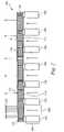
- FIG. 3illustrates a preferred embodiment of the pumping element of the present invention.
- the pumping element 300 shown in FIG. 3includes a body having a top surface 308 and a bottom surface 306 .
- the body 302includes pore apertures 316 in the top surface 308 and pore apertures 314 in the bottom surface 306 .
- the body 302includes several non-parallel conduits 304 that channel fluid from the pore apertures 314 in the bottom surface 306 to the pore apertures 316 in the top surface 308 .
- the pore apertures 314 and the pore apertures 316are not evenly spaced to be aligned across the height dimension of the pump body 302 .
- the pore apertures 314 and 316are aligned across the height dimension of the pump body 302 .
- At least one of the conduits 304has a uniform diameter between the pore apertures 314 , 316 . In another embodiment, at least one of the conduits 304 has a varying diameter between the pore apertures 314 , 316 . In another embodiment, two or more conduits 305 in the pump body 302 are cross connected, as shown in FIG. 3 .
- the pump structure 300 in FIG. 3is advantageous, because it is manufacturable at a very low cost using a glass sintering process which is well known in the art. Once the basic porous glass body 302 has been produced, it is possible to deposit or form the electrodes 312 , 310 directly on the top and bottom surfaces 308 , 306 of the pumping structure 300 using any appropriate method as discussed below.
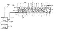
- FIG. 5Aillustrates a schematic view of the pump 500 having the electrode layer applied thereto in accordance with the present invention.
- the pump 500includes the pump body 502 with a dense array of pore apertures 501 in the bottom surface 506 and pore apertures 503 in the top surface 508 .
- the pump body 502includes conduits 504 which channel fluid from the bottom side 506 and the top side 508 of the body 502 .
- the pump 500 in FIG. 5Ais shown to have straight and parallel pore apertures 504 for exemplary purposes.
- the pump 500preferably has a pump body which includes non-parallel and non straight pore apertures and conduits, as shown in FIG. 3 .
- a layer of the electrode 510is disposed upon the bottom side 506 of the body 502 .
- a layer of the electrode 512is applied to the top side of the body 502 .
- the pump 500is coupled to an external power source 514 and an external control circuit 516 by a pair of wires 518 A and 518 B.
- the power sourceis any AC or DC power unit which supplies the appropriate current and voltage to the pump 500 .
- the control circuit 516is coupled to the power source 514 and variably controls the amount of current and voltage applied to the pump 500 to operate the pump at a desired flowrate.
- the electrode layer 510 on the top surface 508is a cathode electrode and the electrode layer 512 on the bottom surface 506 is an anode electrode.
- the electrode layers 510 , 512are made of a material which is highly conductive and has porous characteristics to allow fluid to travel therethrough. The porosity of the electrode layers 510 , 512 are dependent on the type of material used.
- the electrode layers 510 , 512also have a sufficient thickness which generate the desired electrical field across the pump 500 . In addition, the thickness and composition of material in the electrode layers 510 , 512 allow the electrode layers 510 , 512 to be applied to the pump body surfaces 506 , 508 which have a particular roughness.
- the pump body surfaces 506 , 508are smooth, whereby the electrode layers 510 , 512 are applied to the smooth surfaces 506 , 508 .
- the electrode layers 510 , 512preferably provide a uniform surface along both sides of the pump body 502 to generate a uniform electric field across the pump 500 .
- the electrode layers 510 , 512are disposed on the surfaces 506 , 508 of the pump body 502 as a thin film, as shown in FIG. 5A .
- the electrode layers 510 , 512are disposed on the surfaces 506 , 508 as a stratum of multiple layers of film, as shown in FIG. 5B .
- the electrode layers 510 , 512include a several small spheres aligned along the surface and in contact with one another, as shown in FIG. 5D . It should be noted that other configurations of the electrode layers are contemplated by one skilled in the art, wherein the electrode layer generates a substantially uniform electrical field and allows fluid to pass therethrough.
- the thin film of electrodehas an even, consistent thickness along the entire surfaces of the pump body 502 .
- the thin filmis continuous along the entire surface of the pump body 502 , whereby there are no breaks, cracks, or discontinuity in the films 510 , 512 .
- the thin films of electrodes 510 , 512are evenly spaced apart from each other across the pump body 502 .
- the thin films of electrodes 510 , 512have the same thickness so that the electrode layers 510 , 512 , when charged, generate a uniform electric field across the pump body 502 .
- the thin film electrodes 510 , 512have a thickness such that the electrode is continuous over the pump body 502 surface and also allows fluid to travel through the pump body 502 .
- the thickness of the electrodeis within the range of and including 200 and 100,000 Angstroms and preferably has a thickness of 1000 Angstroms.
- it is preferred that the electrodes 510 , 512has a thickness to provide a modest resistance path, such as less than 100 ohms, from one edge of the pumping element to the other edge.
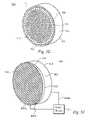
- FIG. 5Cillustrates a perspective view of the pump 600 shown in FIG. 5B .
- the pump 500has a disk shape.
- the pump 500alternatively has any other shape and is not limited to the shape shown in FIG. 5C .
- the pump 600 in FIG. 5Bis shown to have straight and parallel pore apertures 604 for exemplary purposes.
- the pump 600includes non-parallel and non straight pore apertures, as shown in FIG. 3 .
- the pump 600includes a thin film electrode 612 disposed on the top surface 608 as well as another thin film electrode 610 disposed on the bottom surface 606 .
- the pump 600includes a second electrode layer 618 , 620 disposed on top of the thin film electrode 610 , 612 .
- the combined thin film electrode 612 and additional electrode layerthereby forms a multi-layer electrode 618 , 620 .
- the additional electrode layer applied to the thin film electrode 610 , 612is made of the same material, thereby forming a homogeneous multi-layer electrode 618 , 620 .
- the additional electrode layer applied to the thin film electrode 610 , 612is made of a different material, thereby forming a composite multi-layer electrode 618 , 620 .
- the multi-layer electrodes 618 , 620are disposed at predetermined locations along the top and bottom surfaces 610 , 612 of the pump 600 . As shown in FIG. 5B , the multi-layer electrodes 618 B, 620 B disposed on the bottom surface 606 of the pump 600 are disposed to be in the same location opposite of the multi-layer electrodes 618 A, 620 A. Alternatively, the multi-layer electrodes 618 B, 620 B on the bottom surface 606 are disposed not to be in the same location opposite from the multi-layer electrodes 618 A, 620 A.
- the multi-layer electrodesare disposed as two concentric rings or circles 618 A, 618 B, 620 A, 620 B on the top surface 608 and the bottom surface 606 ( FIG. 5B ). It is apparent to one skilled in the art that the multi-layer electrodes 618 , 620 are alternatively disposed as any number of concentric circles. Alternatively, any number of concentric circles are contemplated on the top and bottom surfaces 608 , 606 of the pump 600 . It is apparent to one skilled in the art that it is not necessary that the multi-layered electrodes 618 , 620 be disposed as concentric circles, and alternatively have any other appropriate design or configuration.
- the electrode layers disposed on top of the thin film electrodes 610 , 612are shown in FIGS. 5B and 5C as having a semi-circular cross section.
- the additional electrode layers disposed on the thin film 610 , 612alternatively have any other cross-sectional shape, including but not limited to square, rectangular, triangular and spherical.
- the additional electrode layeris disposed on the surface of the pump as a circular ring with respect to the center.
- the additional electrode layeris disposed along the surface of the pump 700 in any other configuration, including, but not limited to, cross-hatches, straight line patterns and parallel line patterns.
- the pump 600alternatively has the multi layer electrodes 618 , 620 which cover a substantial area of the pump surface 606 , 608 , whereby the thin film electrodes 610 , 612 form notches or indents into the multi layer electrode surfaces 618 , 620 .
- a smaller electrical fieldis present proximal to the locations of the notches, whereas a larger electrical field is present elsewhere across the pump body 600 .
- the multilayer electrodes 618are capable of distributing larger total currents without generating large voltage drops. In some cases, these currents are as large as 500 mA, whereby the total resistance of the electrode is less than 10 ohms.
- the multilayer electrodes 618provide a number of very low-resistance current paths from one edge of the pumping element to other locations on the surface of the pumping element.
- the thicker electrodes in this designwill block a portion of the pores within the pump body, thereby preventing fluid to flow through the pump at those pore locations. It should be noted that all of the pores are not blocked, however. In one embodiment, the thicker electrode regions occupy no more than 20% of the total area of the pumping element. Therefore, at least 80% of the pores in the pumping element are not blocked and are available to pump the fluid therethrough.
- FIG. 5Dillustrates another alternative embodiment of the pump of the present invention.
- the electrode layer 710 , 712include several spherical beads in contact with the top and bottom surface 708 , 706 of the pump 700 as well as in contact with one another.
- the power source 714 and control circuit 706are coupled to the beaded electrode layer 711 to supply current and voltage thereto.
- the pump 700 in FIG. 5Dis shown to have straight and parallel pore apertures 701 , 703 and conduits 704 for exemplary purposes. However, as stated above, the pump 700 alternatively includes non-parallel and non straight pore apertures, as shown in FIG. 3 . As shown in FIG.
- a pair of connecting wires 718 A, 718 Bare coupled to the beaded electrode layers, whereby the connecting wires 718 A, 718 B deliver current to electrode layers 711 .
- the wires 718 A, 718 Bare coupled to an external power source 714 as well as a control circuit 716 .
- the beads 711are made of an electrically conductive material and are in contact with one another along the entire surface of the pump body 702 .
- the beaded electrode layer 711is disposed partially on the surface of the pump body 702 .
- the beads 711allow electrical current to pass along the top and bottom surface 712 , 710 of the pump body 702 to form a voltage potential across the pump 700 .
- the beads 711are spherical and have a diameter range in between and including 1 micron and 500 microns. In one embodiment, the diameter of the beads 711 is 100 microns such that the beads do not block the pores in the pumping element while providing uniform distribution of the electric field and current which is larger than 1 millimeter in area.
- the beads 711 in the electrode layers 710 , 712are in contact with the corresponding top and bottom surfaces 708 , 706 of the pump body 702 . Due to the spherical shape of the beads 711 , small gaps or openings are formed in between the beads 711 when placed in contact with one another. Fluid is thereby able to flow through the pump body 702 by flowing through the gaps in between the beads 711 in the bottom and top electrode layers 710 , 712 . It is preferred that the beads 711 are securely attached to the top and bottom surfaces 706 , 708 of the pump body 702 and do not detach from the pump body 702 due to the force from the fluid being pumped therethrough.
- the beads 711are alternatively placed in any other appropriate location with respect to the pump body 702 .
- the beads 711are not attached to surfaces 706 , 708 , but are alternatively packed tightly within an enclosure (not shown), such as a glass pump housing, which houses the pump body 702 .
- the beaded electrode layer 711is configured to have a predetermined number of larger diameter beads 713 among the smaller diameter beads in the beaded electrode layer 711 .
- the larger beads 713are within the range and including 100 microns and 500 microns, whereas the smaller beads (not shown) are within the range and including 1 micron and 25 microns. With respect to the surface of the pump body, the larger diameter beads 713 will present a thicker electrode layer than the smaller diameter beads.
- the larger diameter beads 713are placed in predetermined locations of the pump body 702 such that the fluid is able to sufficiently flow through the pump body 702 . As shown in FIG.
- the larger beads 713are disposed in a circular ring among the smaller beads 711 .
- the larger beads 713are disposed along the surface of the pump 700 in any other configuration.
- the spherical beads 711are alternatively disposed on the thin film electrodes 510 , 512 in FIG. 5A .
- the cathode electrode 512 and anode electrodes 510are charged by supplying voltage from the power source 514 to the electrodes 510 , 512 .
- the power sourceis coupled to the pump 500 by a pair of wires 518 A, 518 B, whereby the wires 518 A, 518 B are physically in contact with the electrode layers 510 , 512 .
- FIG. 5Bthe outer perimeter of the pump in FIG.
- 5Bis made of solid fused-glass 622 , whereby the wires 624 A, 624 B are physically coupled to the conducting surface on the fused glass portion 622 and provide electrical current to the electrodes 610 , 612 through the conducting surface on fused glass portion 622 .
- the fused glass portion 622 of the pump 600provides one or more rigid non-porous surfaces to attach the pump 600 to a pump housing (not shown) or other enclosure.
- the fused glass portion 622is attached to one or more desired surfaces by soldering, thereby avoiding the use of solder wicking through the frit and shorting out the pump 600 . It is apparent to one skilled in the art that other methods of attaching the fused glass portion 622 to the desired surfaces are contemplated.
- the fused glassis preferably made of borosilicate glass.
- other glasses or ceramicsare used in the outer perimeter of the pump including, but not limited to Quartz, pure Silicon Dioxide and insulating ceramics.
- the pump 600includes the fused glass portion 622 along the entire outer perimeter.
- the pump 600includes the fused glass portion 622 along one side of the pump body 602 .
- the fused glass portion 622is not limited to the embodiment in FIG. 5B , and are also be applied to the other pump embodiments.
- the pump 800includes a dense screen or wire mesh 804 coupled thereto.
- the screen electrode 804is made or treated to be electrically conductive and is coupled to the top and/or bottom surface 812 of the pump body 802 .
- the screen electrode 804is mechanically coupled to the surface 812 of the pump body 802 .
- the screen electrode 804is coupled to the surface of the pump body 802 by an adhesive material 814 .
- the screen electrode 804is disposed on the thin film electrode ( FIG. 5A ). As shown in FIG.
- the screen electrode 804includes several apertures within the lattice configuration of fibers, whereby the fluid flows through the apertures.
- the individual fibers in the screen electrode 804are separated by a distance smaller than the distance in between the top 812 and bottom surfaces 810 of the pump body 802 .
- the individual fibers in the screen electrode 804are separated by a distance larger than or equal to the distance in between the top 812 and bottom surfaces 810 of the pump body 802 .
- the pumping structureis formed initially by any appropriate method, as in step 200 in FIG. 7 .
- the pump of the present inventionis manufacturable several different ways.
- non-parallel, complex shaped pore apertures 511 shown in FIG. 3 in the frit pumpare fabricated by sintering or pressing powders into the pump element material.
- sintered borosilicate glass disksare fabricated for industrial water filtration applications, and are suitable for this application.
- Other sintered powdersincluding but not limited to Silicon Nitride, Silicon Dioxide, Silicon Carbide, ceramic materials such as Alumina, Titania, Zirconia are alternatively used.
- the poresare irregular and nonuniform, but the fabrication process is extremely inexpensive.
- the pumpis made by a series of lithographic/etching steps, such as those used in conventional integrated circuit manufacturing, to make parallel pore apertures ( FIGS. 5A–5D ) or non-parallel pore apertures 511 ( FIG. 3 ). Details of these manufacturing steps are discussed in co-pending U.S. patent application Ser. No. 10/366,121, filed Feb. 12, 2003 and entitled, “MICRO-FABRICATED ELECTROKINETIC PUMP,” which is hereby incorporated by reference.
- the electrodesare formed onto the pump.
- the electrodes 510 , 512are fabricated from materials that do not electrically decompose during the operation of the pump.
- the electrode layersare preferably made from Platinum.
- the electrodesare made from other materials including, but not limited to, Palladium, Tungsten, Nickel, Copper, Gold, Silver, Stainless Steel, Niobium, Graphite, any appropriate adhesive materials and metals or a combination thereof.
- the cathode electrodes 512are made from the same material as the anode electrodes 510 , although it is not necessary. For instance, in some pumped fluid chemistries, the cathode electrodes and anode electrodes are made of different materials to properly support operation of the pump.
- the electrode layer 312is formed on the top surface 308 of the pumping element body 302 as in step 202 .
- the electrode layer 314is formed on the bottom surface 306 of the pumping element body 302 as in step 204 .
- Some application methods of the electrode layer onto the pumpinclude but are not limited to: sputtering, evaporating, screen printing, spraying, dispensing, dipping, spinning, conductive ink printing, chemical vapor deposition (CVD), plasma vapor deposition (PVD) or other patterning processes.
- the multi-layer electrodes described in relation to FIGS. 5B and 5Care applied to the pump by disposing additional electrode layers at desired locations on the surface or surfaces of the pumping structure as in step 206 in FIG. 7 .
- Additional electrode layersare applied to the pump 600 by depositing metal or silver epoxy onto the thin film electrode 610 , 612 .
- Other conventional methodsinclude, but are not limited to, using conductive ink, screen printing, patterning, shadow masking, and dipping.
- the beaded electrode layers 710 , 712are applied to the pump 700 using a variety of conventional methods, including, but not limited to, screen printing, sputtering, evaporating, dispensing, dipping, spinning, spraying or dense packing in the package.
- conventional methodsincluding, but not limited to, screen printing, sputtering, evaporating, dispensing, dipping, spinning, spraying or dense packing in the package.
- the above mentioned methodsare well known in the art and are not discussed in detail herein.
- the electrodes coupled to the pumping element of the present inventionare not limited to the methods described above and encompass other appropriate methods known in the art.
- the electrical connectors 318 A, 318 Bare coupled to the electrodes 310 , 312 respectively, as in step 208 .
- the electrical connectorsare 318 A, 318 B are placed in physical contact with the electrode layers 310 , 312 .
- the electrical connectors 318 A, 318 Bare coupled to the conducting surface on the fused glass portion 622 of the pump body ( FIG. 5B ).
- the power source 314is coupled to the electrode layers 310 , 312 , as in step 210 , whereby the control circuit 320 controls the amount of current and voltage supplied to the electrode layers 310 , 312 .
- FIG. 4illustrates a cooling system for cooling a fluid passing through a heat emitting device, such as a microprocessor.
- the systemis a closed loop whereby liquid travels to an element to be cooled, such as a microprocessor 602 , whereby heat transfer occurs between the processor and the liquid.
- the liquidAfter the leaving the microprocessor 602 , the liquid is at an elevated temperature of more than 55° C. and enters the heat exchanger 604 , wherein the liquid is cooled to less than 45° C.
- the liquidthen enters the pump 600 of the present invention at a lower temperature.
- the cooled liquidenters the support apertures 108 and is pumped through the pore apertures 110 by the osmotic process described above.
Landscapes
- Engineering & Computer Science (AREA)
- Mechanical Engineering (AREA)
- General Engineering & Computer Science (AREA)
- Structures Of Non-Positive Displacement Pumps (AREA)
Abstract
Description
As shown in equations (1) and (2), Q is the flow rate of the liquid flowing through the pump and ΔP is the pressure drop across the pump and the variable a is the diameter of the pore aperture. In addition, the variable ψ is the porosity of the pore apertures, ζ is the zeta potential, ε is the permittivity of the liquid, V is the voltage across the pore apertures, A is the total Area of the pump, τ is the tortuosity, μ is the viscosity and L is the thickness of the pumping element. The terms in the parenthesis shown in equations (1) and (2) are corrections for the case in which the pore diameters approach the size of the charged layer, called the Debye Layer, λD, which is only a few nanometers. For pore apertures having a diameter in the 0.1 micrometer to 0.1 mm range, these expressions simplify to be approximately:
Claims (49)
Priority Applications (1)
| Application Number | Priority Date | Filing Date | Title |
|---|---|---|---|
| US10/669,495US7086839B2 (en) | 2002-09-23 | 2003-09-23 | Micro-fabricated electrokinetic pump with on-frit electrode |
Applications Claiming Priority (4)
| Application Number | Priority Date | Filing Date | Title |
|---|---|---|---|
| US41319402P | 2002-09-23 | 2002-09-23 | |
| US44238303P | 2003-01-24 | 2003-01-24 | |
| US10/366,121US6881039B2 (en) | 2002-09-23 | 2003-02-12 | Micro-fabricated electrokinetic pump |
| US10/669,495US7086839B2 (en) | 2002-09-23 | 2003-09-23 | Micro-fabricated electrokinetic pump with on-frit electrode |
Related Parent Applications (1)
| Application Number | Title | Priority Date | Filing Date |
|---|---|---|---|
| US10/366,121Continuation-In-PartUS6881039B2 (en) | 2002-09-23 | 2003-02-12 | Micro-fabricated electrokinetic pump |
Publications (2)
| Publication Number | Publication Date |
|---|---|
| US20040101421A1 US20040101421A1 (en) | 2004-05-27 |
| US7086839B2true US7086839B2 (en) | 2006-08-08 |
Family
ID=32110788
Family Applications (1)
| Application Number | Title | Priority Date | Filing Date |
|---|---|---|---|
| US10/669,495Expired - LifetimeUS7086839B2 (en) | 2002-09-23 | 2003-09-23 | Micro-fabricated electrokinetic pump with on-frit electrode |
Country Status (3)
| Country | Link |
|---|---|
| US (1) | US7086839B2 (en) |
| AU (1) | AU2003270882A1 (en) |
| WO (1) | WO2004036040A1 (en) |
Cited By (34)
| Publication number | Priority date | Publication date | Assignee | Title |
|---|---|---|---|---|
| US20060147741A1 (en)* | 2004-12-30 | 2006-07-06 | Instrument Technology Research Center | Composite plate device for thermal transpiration micropump |
| US20060207883A1 (en)* | 2004-10-19 | 2006-09-21 | Koval Carl A | Electrochemical high pressure pump |
| US20060275138A1 (en)* | 2005-06-03 | 2006-12-07 | The Hong Kong University Of Science And Technology | Membrane nanopumps based on porous alumina thin films, membranes therefor and a method of fabricating such membranes |
| US20070068815A1 (en)* | 2005-09-26 | 2007-03-29 | Industrial Technology Research Institute | Micro electro-kinetic pump having a nano porous membrane |
| US20070205359A1 (en)* | 2006-03-01 | 2007-09-06 | Ulrich Bonne | Electronic gas pump |
| US20080260542A1 (en)* | 2004-06-07 | 2008-10-23 | Nano Fusion Technologies, Inc | Electroosmotic Pump System and Electroosmotic Pump |
| US20090046429A1 (en)* | 2007-08-07 | 2009-02-19 | Werner Douglas E | Deformable duct guides that accommodate electronic connection lines |
| US20090126813A1 (en)* | 2005-03-30 | 2009-05-21 | Nano Fusion Technologies, Inc. | Liquid-Transport Device and System |
| US20090136362A1 (en)* | 2005-03-30 | 2009-05-28 | Nano Fusion Technologies Inc. | Electroosmosis Pump and Liquid Feeding Device |
| US7599184B2 (en) | 2006-02-16 | 2009-10-06 | Cooligy Inc. | Liquid cooling loops for server applications |
| US7715194B2 (en) | 2006-04-11 | 2010-05-11 | Cooligy Inc. | Methodology of cooling multiple heat sources in a personal computer through the use of multiple fluid-based heat exchanging loops coupled via modular bus-type heat exchangers |
| US20100150738A1 (en)* | 2006-02-24 | 2010-06-17 | Jan Gimsa | Electrohydrodynamic Micropump and Its Use |
| US7806168B2 (en) | 2002-11-01 | 2010-10-05 | Cooligy Inc | Optimal spreader system, device and method for fluid cooled micro-scaled heat exchange |
| US7836597B2 (en) | 2002-11-01 | 2010-11-23 | Cooligy Inc. | Method of fabricating high surface to volume ratio structures and their integration in microheat exchangers for liquid cooling system |
| US7913719B2 (en) | 2006-01-30 | 2011-03-29 | Cooligy Inc. | Tape-wrapped multilayer tubing and methods for making the same |
| US20110097215A1 (en)* | 2009-10-23 | 2011-04-28 | The Government Of The United States Of America, As Represented By The Secretary Of The Navy | Flexible Solid-State Pump Constructed of Surface-Modified Glass Fiber Filters and Metal Mesh Electrodes |
| US20110149252A1 (en)* | 2009-12-21 | 2011-06-23 | Matthew Keith Schwiebert | Electrohydrodynamic Air Mover Performance |
| US8157001B2 (en) | 2006-03-30 | 2012-04-17 | Cooligy Inc. | Integrated liquid to air conduction module |
| US8250877B2 (en) | 2008-03-10 | 2012-08-28 | Cooligy Inc. | Device and methodology for the removal of heat from an equipment rack by means of heat exchangers mounted to a door |
| US8254422B2 (en) | 2008-08-05 | 2012-08-28 | Cooligy Inc. | Microheat exchanger for laser diode cooling |
| US8602092B2 (en) | 2003-07-23 | 2013-12-10 | Cooligy, Inc. | Pump and fan control concepts in a cooling system |
| WO2014031596A1 (en)* | 2012-08-20 | 2014-02-27 | Cornell University | System and methods for actuation using electro-osmosis |
| US20140070663A1 (en)* | 2012-09-11 | 2014-03-13 | Rutgers, The State University Of New Jersey | Electrokinetic nanothrusters and applications thereof |
| US9314567B2 (en) | 2010-03-09 | 2016-04-19 | Board Of Regents Of The University Of Texas System | Electro-osmotic pumps, systems, methods, and compositions |
| US20160252082A1 (en)* | 2013-10-22 | 2016-09-01 | Sekisui Chemical Co., Ltd. | Electroosmotic pump |
| US20160298617A1 (en)* | 2013-12-04 | 2016-10-13 | Apr Technologies Ab | Microfluidic device |
| US9931462B2 (en) | 2012-09-21 | 2018-04-03 | Board Of Regents Of The University Of Texas System | Electro-osmotic pumps with electrodes comprising a lanthanide oxide or an actinide oxide |
| US10107573B1 (en)* | 2014-01-10 | 2018-10-23 | Science Research Laboratory, Inc. | Methods for protecting cooling ports from electro-corrosion in stacked coolers and articles made using the methods |
| US20230301019A1 (en)* | 2022-03-18 | 2023-09-21 | Baidu Usa Llc | System on a chip based cooling system |
| US20230422441A1 (en)* | 2022-06-25 | 2023-12-28 | EvansWerks, Inc. | Cooling system and methods |
| US12133365B2 (en) | 2022-06-25 | 2024-10-29 | EvansWerks, Inc. | Cooling system and methods |
| US12141508B2 (en) | 2020-03-16 | 2024-11-12 | Washington University | Systems and methods for forming micropillar array |
| US12200908B2 (en) | 2022-06-25 | 2025-01-14 | EvansWerks, Inc. | Cooling system and methods |
| US12363864B2 (en) | 2022-06-25 | 2025-07-15 | EvansWerks, Inc. | Cooling system and methods |
Families Citing this family (23)
| Publication number | Priority date | Publication date | Assignee | Title |
|---|---|---|---|---|
| US20030098661A1 (en)* | 2001-11-29 | 2003-05-29 | Ken Stewart-Smith | Control system for vehicle seats |
| WO2004015378A1 (en)* | 2002-07-05 | 2004-02-19 | Gaspardo Seminatrici S.P.A. | A volumetric metering device for the metered delivery of granular and powdery materials, particularly for machines for distributing the said materials |
| US7364647B2 (en)* | 2002-07-17 | 2008-04-29 | Eksigent Technologies Llc | Laminated flow device |
| US7235164B2 (en) | 2002-10-18 | 2007-06-26 | Eksigent Technologies, Llc | Electrokinetic pump having capacitive electrodes |
| US7517440B2 (en)* | 2002-07-17 | 2009-04-14 | Eksigent Technologies Llc | Electrokinetic delivery systems, devices and methods |
| US6881039B2 (en) | 2002-09-23 | 2005-04-19 | Cooligy, Inc. | Micro-fabricated electrokinetic pump |
| US7293423B2 (en) | 2004-06-04 | 2007-11-13 | Cooligy Inc. | Method and apparatus for controlling freezing nucleation and propagation |
| US7201012B2 (en) | 2003-01-31 | 2007-04-10 | Cooligy, Inc. | Remedies to prevent cracking in a liquid system |
| US6861274B2 (en)* | 2003-03-28 | 2005-03-01 | Intel Corporation | Method of making a SDI electroosmotic pump using nanoporous dielectric frit |
| US7559356B2 (en) | 2004-04-19 | 2009-07-14 | Eksident Technologies, Inc. | Electrokinetic pump driven heat transfer system |
| US7779648B2 (en)* | 2004-11-01 | 2010-08-24 | Tecumseh Products Company | Heat exchanger with enhanced air distribution |
| GB2431667B (en)* | 2005-10-28 | 2011-01-05 | Univ Hull | Devices with a passageway for electroosmotic flow and method of making same |
| DK1957794T3 (en)* | 2005-11-23 | 2014-08-11 | Eksigent Technologies Llc | Electrokinetic pump designs and drug delivery systems |
| US7867592B2 (en) | 2007-01-30 | 2011-01-11 | Eksigent Technologies, Inc. | Methods, compositions and devices, including electroosmotic pumps, comprising coated porous surfaces |
| WO2009076134A1 (en)* | 2007-12-11 | 2009-06-18 | Eksigent Technologies, Llc | Electrokinetic pump with fixed stroke volume |
| WO2010124263A2 (en)* | 2009-04-24 | 2010-10-28 | Old Dominion University Research Foundation | Electroosmotic pump |
| JP2014519570A (en) | 2011-05-05 | 2014-08-14 | エクシジェント テクノロジーズ, エルエルシー | Gel coupling for electrokinetic delivery system |
| JP6439326B2 (en) | 2014-08-29 | 2018-12-19 | 株式会社Ihi | Reactor |
| KR102547256B1 (en)* | 2018-02-13 | 2023-06-23 | (주)포인트엔지니어링 | Electroosmotic pump |
| KR102366003B1 (en)* | 2017-12-08 | 2022-02-22 | (주)포인트엔지니어링 | Membrane for electroosmotic pump and electroosmotic pump having the same |
| KR102342726B1 (en)* | 2017-11-13 | 2021-12-24 | (주)포인트엔지니어링 | Membrane for electroosmotic pump and electroosmotic pump having the same |
| KR20210116750A (en)* | 2020-03-13 | 2021-09-28 | 이오플로우(주) | Membrane-electrode assembly for electroosmotic pump, electroosmotic pump and system for pumping of fluid comprising thereof |
| KR20210116751A (en)* | 2020-03-13 | 2021-09-28 | 이오플로우(주) | Electroosmotic pump, method for preparing thereof, and system for pumping of fluid comprising thereof |
Citations (223)
| Publication number | Priority date | Publication date | Assignee | Title |
|---|---|---|---|---|
| US596062A (en) | 1897-12-28 | Device for preventing bursting of freezing pipes | ||
| US2039593A (en) | 1935-06-20 | 1936-05-05 | Theodore N Hubbuch | Heat transfer coil |
| US2273505A (en) | 1942-02-17 | Container | ||
| US3267859A (en) | 1964-02-18 | 1966-08-23 | Sakari T Jutila | Liquid dielectric pump |
| US3361195A (en) | 1966-09-23 | 1968-01-02 | Westinghouse Electric Corp | Heat sink member for a semiconductor device |
| US3554669A (en) | 1968-12-04 | 1971-01-12 | Gen Electric | Electric-fluid energy converter |
| US3654988A (en) | 1970-02-24 | 1972-04-11 | American Standard Inc | Freeze protection for outdoor cooler |
| US3771219A (en) | 1970-02-05 | 1973-11-13 | Sharp Kk | Method for manufacturing semiconductor device |
| US3817321A (en) | 1971-01-19 | 1974-06-18 | Bosch Gmbh Robert | Cooling apparatus semiconductor elements, comprising partitioned bubble pump, separator and condenser means |
| US3823572A (en) | 1973-08-15 | 1974-07-16 | American Air Filter Co | Freeze protection device in heat pump system |
| US3923426A (en) | 1974-08-15 | 1975-12-02 | Alza Corp | Electroosmotic pump and fluid dispenser including same |
| US3929154A (en) | 1974-07-29 | 1975-12-30 | Frank E Goodwin | Freeze protection apparatus |
| US3948316A (en) | 1973-02-06 | 1976-04-06 | Gaz De France | Process of and device for using the energy given off by a heat source |
| US4109707A (en) | 1975-07-02 | 1978-08-29 | Honeywell Information Systems, Inc. | Fluid cooling systems for electronic systems |
| US4138996A (en) | 1977-07-28 | 1979-02-13 | Rheem Manufacturing Company | Solar heater freeze protection system |
| US4194559A (en) | 1978-11-01 | 1980-03-25 | Thermacore, Inc. | Freeze accommodating heat pipe |
| US4211208A (en) | 1976-12-24 | 1980-07-08 | Deutsche Forschungs- Und Versuchsanstalt Fur Luft- Und Raumfahrt E.V. | Container for a heat storage medium |
| US4248295A (en) | 1980-01-17 | 1981-02-03 | Thermacore, Inc. | Freezable heat pipe |
| US4312012A (en) | 1977-11-25 | 1982-01-19 | International Business Machines Corp. | Nucleate boiling surface for increasing the heat transfer from a silicon device to a liquid coolant |
| US4450472A (en) | 1981-03-02 | 1984-05-22 | The Board Of Trustees Of The Leland Stanford Junior University | Method and means for improved heat removal in compact semiconductor integrated circuits and similar devices utilizing coolant chambers and microscopic channels |
| US4485429A (en) | 1982-06-09 | 1984-11-27 | Sperry Corporation | Apparatus for cooling integrated circuit chips |
| US4516632A (en) | 1982-08-31 | 1985-05-14 | The United States Of America As Represented By The United States Deparment Of Energy | Microchannel crossflow fluid heat exchanger and method for its fabrication |
| US4540115A (en) | 1983-08-26 | 1985-09-10 | Rca Corporation | Flux-free photodetector bonding |
| US4561040A (en) | 1984-07-12 | 1985-12-24 | Ibm Corporation | Cooling system for VLSI circuit chips |
| US4567505A (en) | 1983-10-27 | 1986-01-28 | The Board Of Trustees Of The Leland Stanford Junior University | Heat sink and method of attaching heat sink to a semiconductor integrated circuit and the like |
| US4573067A (en) | 1981-03-02 | 1986-02-25 | The Board Of Trustees Of The Leland Stanford Junior University | Method and means for improved heat removal in compact semiconductor integrated circuits |
| US4574876A (en) | 1981-05-11 | 1986-03-11 | Extracorporeal Medical Specialties, Inc. | Container with tapered walls for heating or cooling fluids |
| US4644385A (en) | 1983-10-28 | 1987-02-17 | Hitachi, Ltd. | Cooling module for integrated circuit chips |
| US4664181A (en) | 1984-03-05 | 1987-05-12 | Thermo Electron Corporation | Protection of heat pipes from freeze damage |
| US4758926A (en) | 1986-03-31 | 1988-07-19 | Microelectronics And Computer Technology Corporation | Fluid-cooled integrated circuit package |
| US4866570A (en) | 1988-08-05 | 1989-09-12 | Ncr Corporation | Apparatus and method for cooling an electronic device |
| US4868712A (en) | 1987-02-04 | 1989-09-19 | Woodman John K | Three dimensional integrated circuit package |
| US4893174A (en) | 1985-07-08 | 1990-01-09 | Hitachi, Ltd. | High density integration of semiconductor circuit |
| US4894709A (en) | 1988-03-09 | 1990-01-16 | Massachusetts Institute Of Technology | Forced-convection, liquid-cooled, microchannel heat sinks |
| US4896719A (en) | 1988-05-11 | 1990-01-30 | Mcdonnell Douglas Corporation | Isothermal panel and plenum |
| US4908112A (en) | 1988-06-16 | 1990-03-13 | E. I. Du Pont De Nemours & Co. | Silicon semiconductor wafer for analyzing micronic biological samples |
| US4938280A (en) | 1988-11-07 | 1990-07-03 | Clark William E | Liquid-cooled, flat plate heat exchanger |
| US5009760A (en) | 1989-07-28 | 1991-04-23 | Board Of Trustees Of The Leland Stanford Junior University | System for measuring electrokinetic properties and for characterizing electrokinetic separations by monitoring current in electrophoresis |
| US5016138A (en) | 1987-10-27 | 1991-05-14 | Woodman John K | Three dimensional integrated circuit package |
| US5043797A (en) | 1990-04-03 | 1991-08-27 | General Electric Company | Cooling header connection for a thyristor stack |
| US5057908A (en) | 1990-07-10 | 1991-10-15 | Iowa State University Research Foundation, Inc. | High power semiconductor device with integral heat sink |
| US5058627A (en) | 1989-04-10 | 1991-10-22 | Brannen Wiley W | Freeze protection system for water pipes |
| US5070040A (en) | 1990-03-09 | 1991-12-03 | University Of Colorado Foundation, Inc. | Method and apparatus for semiconductor circuit chip cooling |
| US5083194A (en) | 1990-01-16 | 1992-01-21 | Cray Research, Inc. | Air jet impingement on miniature pin-fin heat sinks for cooling electronic components |
| US5088005A (en) | 1990-05-08 | 1992-02-11 | Sundstrand Corporation | Cold plate for cooling electronics |
| US5096388A (en) | 1990-03-22 | 1992-03-17 | The Charles Stark Draper Laboratory, Inc. | Microfabricated pump |
| US5099311A (en) | 1991-01-17 | 1992-03-24 | The United States Of America As Represented By The United States Department Of Energy | Microchannel heat sink assembly |
| US5099910A (en) | 1991-01-15 | 1992-03-31 | Massachusetts Institute Of Technology | Microchannel heat sink with alternating flow directions |
| US5125451A (en) | 1991-04-02 | 1992-06-30 | Microunity Systems Engineering, Inc. | Heat exchanger for solid-state electronic devices |
| US5131233A (en) | 1991-03-08 | 1992-07-21 | Cray Computer Corporation | Gas-liquid forced turbulence cooling |
| US5161089A (en) | 1990-06-04 | 1992-11-03 | International Business Machines Corporation | Enhanced multichip module cooling with thermally optimized pistons and closely coupled convective cooling channels, and methods of manufacturing the same |
| US5179500A (en) | 1990-02-27 | 1993-01-12 | Grumman Aerospace Corporation | Vapor chamber cooled electronic circuit card |
| US5203401A (en) | 1990-06-29 | 1993-04-20 | Digital Equipment Corporation | Wet micro-channel wafer chuck and cooling method |
| US5218515A (en) | 1992-03-13 | 1993-06-08 | The United States Of America As Represented By The United States Department Of Energy | Microchannel cooling of face down bonded chips |
| US5219278A (en) | 1989-11-10 | 1993-06-15 | Westonbridge International, Ltd. | Micropump with improved priming |
| US5228502A (en) | 1991-09-04 | 1993-07-20 | International Business Machines Corporation | Cooling by use of multiple parallel convective surfaces |
| US5232047A (en) | 1991-04-02 | 1993-08-03 | Microunity Systems Engineering, Inc. | Heat exchanger for solid-state electronic devices |
| US5239200A (en) | 1991-08-21 | 1993-08-24 | International Business Machines Corporation | Apparatus for cooling integrated circuit chips |
| US5239443A (en) | 1992-04-23 | 1993-08-24 | International Business Machines Corporation | Blind hole cold plate cooling system |
| US5263251A (en) | 1991-04-02 | 1993-11-23 | Microunity Systems Engineering | Method of fabricating a heat exchanger for solid-state electronic devices |
| US5265670A (en) | 1990-04-27 | 1993-11-30 | International Business Machines Corporation | Convection transfer system |
| US5308429A (en) | 1992-09-29 | 1994-05-03 | Digital Equipment Corporation | System for bonding a heatsink to a semiconductor chip package |
| US5309319A (en) | 1991-02-04 | 1994-05-03 | International Business Machines Corporation | Integral cooling system for electric components |
| US5316077A (en) | 1992-12-09 | 1994-05-31 | Eaton Corporation | Heat sink for electrical circuit components |
| US5317805A (en) | 1992-04-28 | 1994-06-07 | Minnesota Mining And Manufacturing Company | Method of making microchanneled heat exchangers utilizing sacrificial cores |
| US5325265A (en) | 1988-11-10 | 1994-06-28 | Mcnc | High performance integrated circuit chip package |
| US5336062A (en) | 1990-02-27 | 1994-08-09 | Fraunhofer-Gesellschaft Zur Forderung Der Angewandten Forschung E.V. | Microminiaturized pump |
| US5371529A (en) | 1991-10-17 | 1994-12-06 | Sony Corporation | Ink-jet print head and ink-jet printer |
| US5380956A (en) | 1993-07-06 | 1995-01-10 | Sun Microsystems, Inc. | Multi-chip cooling module and method |
| US5383340A (en) | 1994-03-24 | 1995-01-24 | Aavid Laboratories, Inc. | Two-phase cooling system for laptop computers |
| US5386143A (en) | 1991-10-25 | 1995-01-31 | Digital Equipment Corporation | High performance substrate, electronic package and integrated circuit cooling process |
| US5421943A (en) | 1991-11-22 | 1995-06-06 | International Business Machines Corporation | Pulsed current resistive heating for bonding temperature critical components |
| US5427174A (en) | 1993-04-30 | 1995-06-27 | Heat Transfer Devices, Inc. | Method and apparatus for a self contained heat exchanger |
| US5436793A (en) | 1993-03-31 | 1995-07-25 | Ncr Corporation | Apparatus for containing and cooling an integrated circuit device having a thermally insulative positioning member |
| US5441613A (en) | 1993-12-03 | 1995-08-15 | Dionex Corporation | Methods and apparatus for real-time monitoring, measurement and control of electroosmotic flow |
| US5459099A (en) | 1990-09-28 | 1995-10-17 | The United States Of America As Represented By The Secretary Of The Navy | Method of fabricating sub-half-micron trenches and holes |
| US5490117A (en) | 1993-03-23 | 1996-02-06 | Seiko Epson Corporation | IC card with dual level power supply interface and method for operating the IC card |
| US5508234A (en) | 1994-10-31 | 1996-04-16 | International Business Machines Corporation | Microcavity structures, fabrication processes, and applications thereof |
| US5514906A (en) | 1993-11-10 | 1996-05-07 | Fujitsu Limited | Apparatus for cooling semiconductor chips in multichip modules |
| US5534471A (en) | 1994-01-12 | 1996-07-09 | Air Products And Chemicals, Inc. | Ion transport membranes with catalyzed mixed conducting porous layer |
| US5544696A (en) | 1994-07-01 | 1996-08-13 | The United States Of America As Represented By The Secretary Of The Air Force | Enhanced nucleate boiling heat transfer for electronic cooling and thermal energy transfer |
| US5548605A (en) | 1995-05-15 | 1996-08-20 | The Regents Of The University Of California | Monolithic microchannel heatsink |
| US5579828A (en) | 1996-01-16 | 1996-12-03 | Hudson Products Corporation | Flexible insert for heat pipe freeze protection |
| US5585069A (en) | 1994-11-10 | 1996-12-17 | David Sarnoff Research Center, Inc. | Partitioned microelectronic and fluidic device array for clinical diagnostics and chemical synthesis |
| US5632876A (en) | 1995-06-06 | 1997-05-27 | David Sarnoff Research Center, Inc. | Apparatus and methods for controlling fluid flow in microchannels |
| US5641400A (en) | 1994-10-19 | 1997-06-24 | Hewlett-Packard Company | Use of temperature control devices in miniaturized planar column devices and miniaturized total analysis systems |
| US5658831A (en) | 1993-03-31 | 1997-08-19 | Unisys Corporation | Method of fabricating an integrated circuit package having a liquid metal-aluminum/copper joint |
| US5675473A (en) | 1996-02-23 | 1997-10-07 | Motorola, Inc. | Apparatus and method for shielding an electronic module from electromagnetic radiation |
| US5692558A (en) | 1996-07-22 | 1997-12-02 | Northrop Grumman Corporation | Microchannel cooling using aviation fuels for airborne electronics |
| US5696405A (en) | 1995-10-13 | 1997-12-09 | Lucent Technologies Inc. | Microelectronic package with device cooling |
| US5703536A (en) | 1996-04-08 | 1997-12-30 | Harris Corporation | Liquid cooling system for high power solid state AM transmitter |
| US5704416A (en) | 1993-09-10 | 1998-01-06 | Aavid Laboratories, Inc. | Two phase component cooler |
| US5727618A (en) | 1993-08-23 | 1998-03-17 | Sdl Inc | Modular microchannel heat exchanger |
| US5740013A (en) | 1996-07-03 | 1998-04-14 | Hewlett-Packard Company | Electronic device enclosure having electromagnetic energy containment and heat removal characteristics |
| JPH1099592A (en) | 1996-09-27 | 1998-04-21 | Matsushita Electric Ind Co Ltd | Pump equipment for washing machines, etc. |
| US5759014A (en) | 1994-01-14 | 1998-06-02 | Westonbridge International Limited | Micropump |
| US5763951A (en) | 1996-07-22 | 1998-06-09 | Northrop Grumman Corporation | Non-mechanical magnetic pump for liquid cooling |
| US5768104A (en) | 1996-02-22 | 1998-06-16 | Cray Research, Inc. | Cooling approach for high power integrated circuits mounted on printed circuit boards |
| US5774779A (en) | 1996-11-06 | 1998-06-30 | Materials And Electrochemical Research (Mer) Corporation | Multi-channel structures and processes for making such structures |
| US5801442A (en) | 1996-07-22 | 1998-09-01 | Northrop Grumman Corporation | Microchannel cooling of high power semiconductor devices |
| US5800690A (en) | 1996-07-03 | 1998-09-01 | Caliper Technologies Corporation | Variable control of electroosmotic and/or electrophoretic forces within a fluid-containing structure via electrical forces |
| US5835345A (en) | 1996-10-02 | 1998-11-10 | Sdl, Inc. | Cooler for removing heat from a heated region |
| US5836750A (en) | 1997-10-09 | 1998-11-17 | Honeywell Inc. | Electrostatically actuated mesopump having a plurality of elementary cells |
| US5839290A (en) | 1997-01-24 | 1998-11-24 | United States Of America As Represented By The Secretary Of The Navy | Organic/inorganic composite wicks for caillary pumped loops |
| US5858188A (en) | 1990-02-28 | 1999-01-12 | Aclara Biosciences, Inc. | Acrylic microchannels and their use in electrophoretic applications |
| US5869004A (en) | 1997-06-09 | 1999-02-09 | Caliper Technologies Corp. | Methods and apparatus for in situ concentration and/or dilution of materials in microfluidic systems |
| US5870823A (en) | 1996-11-27 | 1999-02-16 | International Business Machines Corporation | Method of forming a multilayer electronic packaging substrate with integral cooling channels |
| US5874795A (en) | 1995-12-28 | 1999-02-23 | Japan Servo Co., Ltd | Multi-phase permanent-magnet type electric rotating machine |
| US5876655A (en) | 1995-02-21 | 1999-03-02 | E. I. Du Pont De Nemours And Company | Method for eliminating flow wrinkles in compression molded panels |
| US5880017A (en) | 1994-08-08 | 1999-03-09 | Hewlett-Packard Co. | Method of bumping substrates by contained paste deposition |
| US5880524A (en) | 1997-05-05 | 1999-03-09 | Intel Corporation | Heat pipe lid for electronic packages |
| US5901037A (en) | 1997-06-18 | 1999-05-04 | Northrop Grumman Corporation | Closed loop liquid cooling for semiconductor RF amplifier modules |
| US5921087A (en) | 1997-04-22 | 1999-07-13 | Intel Corporation | Method and apparatus for cooling integrated circuits using a thermoelectric module |
| US5936192A (en) | 1996-12-20 | 1999-08-10 | Aisin Seiki Kabushiki Kaisha | Multi-stage electronic cooling device |
| US5940270A (en) | 1998-07-08 | 1999-08-17 | Puckett; John Christopher | Two-phase constant-pressure closed-loop water cooling system for a heat producing device |
| US5942093A (en) | 1997-06-18 | 1999-08-24 | Sandia Corporation | Electro-osmotically driven liquid delivery method and apparatus |
| US5964092A (en) | 1996-12-13 | 1999-10-12 | Nippon Sigmax, Co., Ltd. | Electronic cooling apparatus |
| US5965813A (en) | 1998-07-23 | 1999-10-12 | Industry Technology Research Institute | Integrated flow sensor |
| US5978220A (en) | 1996-10-23 | 1999-11-02 | Asea Brown Boveri Ag | Liquid cooling device for a high-power semiconductor module |
| US5989402A (en) | 1997-08-29 | 1999-11-23 | Caliper Technologies Corp. | Controller/detector interfaces for microfluidic systems |
| US5993750A (en) | 1997-04-11 | 1999-11-30 | Eastman Kodak Company | Integrated ceramic micro-chemical plant |
| US5997713A (en) | 1997-05-08 | 1999-12-07 | Nanosciences Corporation | Silicon etching process for making microchannel plates |
| US6007309A (en) | 1995-12-13 | 1999-12-28 | Hartley; Frank T. | Micromachined peristaltic pumps |
| US6010316A (en) | 1996-01-16 | 2000-01-04 | The Board Of Trustees Of The Leland Stanford Junior University | Acoustic micropump |
| US6013164A (en) | 1997-06-25 | 2000-01-11 | Sandia Corporation | Electokinetic high pressure hydraulic system |
| US6012902A (en) | 1997-09-25 | 2000-01-11 | Caliper Technologies Corp. | Micropump |
| US6019882A (en) | 1997-06-25 | 2000-02-01 | Sandia Corporation | Electrokinetic high pressure hydraulic system |
| US6054034A (en) | 1990-02-28 | 2000-04-25 | Aclara Biosciences, Inc. | Acrylic microchannels and their use in electrophoretic applications |
| US6068752A (en) | 1997-04-25 | 2000-05-30 | Caliper Technologies Corp. | Microfluidic devices incorporating improved channel geometries |
| US6090251A (en) | 1997-06-06 | 2000-07-18 | Caliper Technologies, Inc. | Microfabricated structures for facilitating fluid introduction into microfluidic devices |
| US6096656A (en) | 1999-06-24 | 2000-08-01 | Sandia Corporation | Formation of microchannels from low-temperature plasma-deposited silicon oxynitride |
| US6100541A (en) | 1998-02-24 | 2000-08-08 | Caliper Technologies Corporation | Microfluidic devices and systems incorporating integrated optical elements |
| US6101715A (en) | 1995-04-20 | 2000-08-15 | Daimlerchrysler Ag | Microcooling device and method of making it |
| US6103199A (en)* | 1998-09-15 | 2000-08-15 | Aclara Biosciences, Inc. | Capillary electroflow apparatus and method |
| US6106685A (en)* | 1997-05-13 | 2000-08-22 | Sarnoff Corporation | Electrode combinations for pumping fluids |
| US6119729A (en) | 1998-09-14 | 2000-09-19 | Arise Technologies Corporation | Freeze protection apparatus for fluid transport passages |
| US6126723A (en) | 1994-07-29 | 2000-10-03 | Battelle Memorial Institute | Microcomponent assembly for efficient contacting of fluid |
| JP2000277540A (en) | 1999-03-24 | 2000-10-06 | Fuji Photo Film Co Ltd | Part bonding device |
| US6129145A (en) | 1997-08-28 | 2000-10-10 | Sumitomo Electric Industries, Ltd. | Heat dissipator including coolant passage and method of fabricating the same |
| US6129260A (en) | 1998-08-19 | 2000-10-10 | Fravillig Technologies Company | Solderable structures |
| US6131650A (en) | 1999-07-20 | 2000-10-17 | Thermal Corp. | Fluid cooled single phase heat sink |
| US6140860A (en) | 1997-12-31 | 2000-10-31 | Intel Corporation | Thermal sensing circuit |
| US6146103A (en) | 1998-10-09 | 2000-11-14 | The Regents Of The University Of California | Micromachined magnetohydrodynamic actuators and sensors |
| US6154363A (en) | 1999-12-29 | 2000-11-28 | Chang; Neng Chao | Electronic device cooling arrangement |
| US6159353A (en) | 1997-04-30 | 2000-12-12 | Orion Research, Inc. | Capillary electrophoretic separation system |
| US6167948B1 (en) | 1996-11-18 | 2001-01-02 | Novel Concepts, Inc. | Thin, planar heat spreader |
| US6174675B1 (en) | 1997-11-25 | 2001-01-16 | Caliper Technologies Corp. | Electrical current for controlling fluid parameters in microchannels |
| US6176962B1 (en) | 1990-02-28 | 2001-01-23 | Aclara Biosciences, Inc. | Methods for fabricating enclosed microchannel structures |
| US6186660B1 (en) | 1997-10-09 | 2001-02-13 | Caliper Technologies Corp. | Microfluidic systems incorporating varied channel dimensions |
| US6206022B1 (en) | 1998-10-30 | 2001-03-27 | Industrial Technology Research Institute | Integrated flow controller module |
| US6210986B1 (en) | 1999-09-23 | 2001-04-03 | Sandia Corporation | Microfluidic channel fabrication method |
| US6216343B1 (en) | 1999-09-02 | 2001-04-17 | The United States Of America As Represented By The Secretary Of The Air Force | Method of making micro channel heat pipe having corrugated fin elements |
| US6221226B1 (en) | 1997-07-15 | 2001-04-24 | Caliper Technologies Corp. | Methods and systems for monitoring and controlling fluid flow rates in microfluidic systems |
| US6227809B1 (en) | 1995-03-09 | 2001-05-08 | University Of Washington | Method for making micropumps |
| US6234240B1 (en) | 1999-07-01 | 2001-05-22 | Kioan Cheon | Fanless cooling system for computer |
| US6238538B1 (en) | 1996-04-16 | 2001-05-29 | Caliper Technologies, Corp. | Controlled fluid transport in microfabricated polymeric substrates |
| US6253835B1 (en) | 2000-02-11 | 2001-07-03 | International Business Machines Corporation | Isothermal heat sink with converging, diverging channels |
| US6277257B1 (en) | 1997-06-25 | 2001-08-21 | Sandia Corporation | Electrokinetic high pressure hydraulic system |
| US20010016985A1 (en) | 1998-06-18 | 2001-08-30 | Minnesota Mining And Manufacturing Company | Microchanneled active fluid heat exchanger method |
| US6287440B1 (en) | 1999-06-18 | 2001-09-11 | Sandia Corporation | Method for eliminating gas blocking in electrokinetic pumping systems |
| US20010024820A1 (en) | 2000-02-11 | 2001-09-27 | Ubaldo Mastromatteo | Integrated device microfluid thermoregulation, and manufacturing process thereof |
| US6301109B1 (en) | 2000-02-11 | 2001-10-09 | International Business Machines Corporation | Isothermal heat sink with cross-flow openings between channels |
| US6313992B1 (en) | 1998-12-22 | 2001-11-06 | James J. Hildebrandt | Method and apparatus for increasing the power density of integrated circuit boards and their components |
| US6317326B1 (en) | 2000-09-14 | 2001-11-13 | Sun Microsystems, Inc. | Integrated circuit device package and heat dissipation device |
| US20010044155A1 (en) | 2000-04-13 | 2001-11-22 | Paul Phillip H. | Sample injector for high pressure liquid chromatography |
| JP2001326311A (en) | 2000-05-15 | 2001-11-22 | Hitachi Ltd | Electronic equipment cooling device |
| US6324058B1 (en) | 2000-10-25 | 2001-11-27 | Chieh-Jen Hsiao | Heat-dissipating apparatus for an integrated circuit device |
| US6321791B1 (en) | 1998-01-20 | 2001-11-27 | Caliper Technologies Corp. | Multi-layer microfluidic devices |
| US6322753B1 (en) | 1997-01-24 | 2001-11-27 | Johan Roeraade | Integrated microfluidic element |
| US20010045270A1 (en) | 2000-03-14 | 2001-11-29 | Bhatti Mohinder Singh | High-performance heat sink for electronics cooling |
| US20010046703A1 (en) | 1995-09-15 | 2001-11-29 | The Regents Of The University Of Michigan | Microscale devices and reactions in microscale devices |
| US20010055714A1 (en) | 2000-05-22 | 2001-12-27 | Alstom | Electronic power device |
| US6337794B1 (en) | 2000-02-11 | 2002-01-08 | International Business Machines Corporation | Isothermal heat sink with tiered cooling channels |
| US6351384B1 (en) | 1999-08-11 | 2002-02-26 | Hitachi, Ltd. | Device and method for cooling multi-chip modules |
| US6366467B1 (en) | 2000-03-31 | 2002-04-02 | Intel Corporation | Dual-socket interposer and method of fabrication therefor |
| US6388317B1 (en) | 2000-09-25 | 2002-05-14 | Lockheed Martin Corporation | Solid-state chip cooling by use of microchannel coolant flow |
| US6396706B1 (en) | 1999-07-30 | 2002-05-28 | Credence Systems Corporation | Self-heating circuit board |
| US6397932B1 (en) | 2000-12-11 | 2002-06-04 | Douglas P. Calaman | Liquid-cooled heat sink with thermal jacket |
| US6400012B1 (en) | 1997-09-17 | 2002-06-04 | Advanced Energy Voorhees, Inc. | Heat sink for use in cooling an integrated circuit |
| US6406605B1 (en) | 1999-06-01 | 2002-06-18 | Ysi Incorporated | Electroosmotic flow controlled microfluidic devices |
| US20020075645A1 (en) | 2000-12-20 | 2002-06-20 | Makoto Kitano | Liquid cooling system and personal computer using thereof |
| US6416642B1 (en) | 1999-01-21 | 2002-07-09 | Caliper Technologies Corp. | Method and apparatus for continuous liquid flow in microscale channels using pressure injection, wicking, and electrokinetic injection |
| US6415860B1 (en) | 2000-02-09 | 2002-07-09 | Board Of Supervisors Of Louisiana State University And Agricultural And Mechanical College | Crossflow micro heat exchanger |
| US6417060B2 (en) | 2000-02-25 | 2002-07-09 | Borealis Technical Limited | Method for making a diode device |
| US6424531B1 (en) | 2001-03-13 | 2002-07-23 | Delphi Technologies, Inc. | High performance heat sink for electronics cooling |
| US20020096312A1 (en) | 2000-12-04 | 2002-07-25 | Amos Korin | Membrane desiccation heat pump |
| US6437981B1 (en) | 2000-11-30 | 2002-08-20 | Harris Corporation | Thermally enhanced microcircuit package and method of forming same |
| US6438984B1 (en) | 2001-08-29 | 2002-08-27 | Sun Microsystems, Inc. | Refrigerant-cooled system and method for cooling electronic components |
| US6444461B1 (en) | 1997-04-04 | 2002-09-03 | Caliper Technologies Corp. | Microfluidic devices and methods for separation |
| US6443222B1 (en) | 1999-11-08 | 2002-09-03 | Samsung Electronics Co., Ltd. | Cooling device using capillary pumped loop |
| US20020121105A1 (en) | 2000-12-21 | 2002-09-05 | Mccarthy Joseph H. | Method and system for cooling heat-generating component in a closed-loop system |
| US20020134543A1 (en) | 2001-03-20 | 2002-09-26 | Motorola, Inc | Connecting device with local heating element and method for using same |
| US6457515B1 (en) | 1999-08-06 | 2002-10-01 | The Ohio State University | Two-layered micro channel heat sink, devices and systems incorporating same |
| US6459581B1 (en) | 2000-12-19 | 2002-10-01 | Harris Corporation | Electronic device using evaporative micro-cooling and associated methods |
| US6477045B1 (en) | 2001-12-28 | 2002-11-05 | Tien-Lai Wang | Heat dissipater for a central processing unit |
| US6492200B1 (en) | 1998-06-12 | 2002-12-10 | Hyundai Electronics Industries Co., Inc. | Semiconductor chip package and fabrication method thereof |
| US6495015B1 (en) | 1999-06-18 | 2002-12-17 | Sandia National Corporation | Electrokinetically pumped high pressure sprays |
| US20030022505A1 (en) | 2001-07-24 | 2003-01-30 | Luc Ouellet | Micro-fluidic devices |
| US6537437B1 (en) | 2000-11-13 | 2003-03-25 | Sandia Corporation | Surface-micromachined microfluidic devices |
| US20030062149A1 (en) | 2001-09-28 | 2003-04-03 | Goodson Kenneth E. | Electroosmotic microchannel cooling system |
| US6543521B1 (en) | 1999-10-04 | 2003-04-08 | Matsushita Electric Industrial Co., Ltd. | Cooling element and cooling apparatus using the same |
| US6553253B1 (en) | 1999-03-12 | 2003-04-22 | Biophoretic Therapeutic Systems, Llc | Method and system for electrokinetic delivery of a substance |
| US6578626B1 (en) | 2000-11-21 | 2003-06-17 | Thermal Corp. | Liquid cooled heat exchanger with enhanced flow |
| US6581388B2 (en) | 2001-11-27 | 2003-06-24 | Sun Microsystems, Inc. | Active temperature gradient reducer |
| US6587343B2 (en) | 2001-08-29 | 2003-07-01 | Sun Microsystems, Inc. | Water-cooled system and method for cooling electronic components |
| US20030121274A1 (en) | 2000-09-14 | 2003-07-03 | Wightman David A. | Vapor compression systems, expansion devices, flow-regulating members, and vehicles, and methods for using vapor compression systems |
| US6588498B1 (en) | 2002-07-18 | 2003-07-08 | Delphi Technologies, Inc. | Thermosiphon for electronics cooling with high performance boiling and condensing surfaces |
| US6591625B1 (en) | 2002-04-17 | 2003-07-15 | Agilent Technologies, Inc. | Cooling of substrate-supported heat-generating components |
| US6600220B2 (en) | 2001-05-14 | 2003-07-29 | Hewlett-Packard Company | Power distribution in multi-chip modules |
| US6606251B1 (en) | 2002-02-07 | 2003-08-12 | Cooligy Inc. | Power conditioning module |
| US6632719B1 (en) | 1999-08-30 | 2003-10-14 | Micron Technology, Inc. | Capacitor structures with recessed hemispherical grain silicon |
| US6632655B1 (en) | 1999-02-23 | 2003-10-14 | Caliper Technologies Corp. | Manipulation of microparticles in microfluidic systems |
| US20040040695A1 (en) | 2001-09-20 | 2004-03-04 | Intel Corporation | Modular capillary pumped loop cooling system |
| US20040052049A1 (en) | 2002-09-13 | 2004-03-18 | Wu Bo Jiu | Integrated fluid cooling system for electronic components |
| US6719535B2 (en)* | 2002-01-31 | 2004-04-13 | Eksigent Technologies, Llc | Variable potential electrokinetic device |
| US6729383B1 (en) | 1999-12-16 | 2004-05-04 | The United States Of America As Represented By The Secretary Of The Navy | Fluid-cooled heat sink with turbulence-enhancing support pins |
| US20040089008A1 (en) | 2002-11-12 | 2004-05-13 | Tilton Charles L. | Spray cooling system |
| US6743664B2 (en) | 2000-03-29 | 2004-06-01 | Intel Corporation | Flip-chip on flex for high performance packaging applications |
| US20040120827A1 (en) | 2002-12-18 | 2004-06-24 | Kim Sarah E. | Electro-osmotic pumps and micro-channels |
| US20040125561A1 (en) | 2002-12-27 | 2004-07-01 | Gwin Paul J | Sealed and pressurized liquid cooling system for microprocessor |
| US6770183B1 (en) | 2001-07-26 | 2004-08-03 | Sandia National Laboratories | Electrokinetic pump |
| US20040160741A1 (en) | 2003-02-13 | 2004-08-19 | Dell Products L.P. | Liquid cooling module |
| US20040188069A1 (en) | 2002-08-26 | 2004-09-30 | Kentaro Tomioka | Electronic apparatus having a circulating path of liquid coolant |
Family Cites Families (2)
| Publication number | Priority date | Publication date | Assignee | Title |
|---|---|---|---|---|
| JP2887947B2 (en)* | 1991-06-26 | 1999-05-10 | 日産自動車株式会社 | Air bag grid mounting structure |
| US5575929A (en)* | 1995-06-05 | 1996-11-19 | The Regents Of The University Of California | Method for making circular tubular channels with two silicon wafers |
- 2003
- 2003-09-23WOPCT/US2003/030177patent/WO2004036040A1/ennot_activeApplication Discontinuation
- 2003-09-23AUAU2003270882Apatent/AU2003270882A1/ennot_activeAbandoned
- 2003-09-23USUS10/669,495patent/US7086839B2/ennot_activeExpired - Lifetime
Patent Citations (231)
| Publication number | Priority date | Publication date | Assignee | Title |
|---|---|---|---|---|
| US2273505A (en) | 1942-02-17 | Container | ||
| US596062A (en) | 1897-12-28 | Device for preventing bursting of freezing pipes | ||
| US2039593A (en) | 1935-06-20 | 1936-05-05 | Theodore N Hubbuch | Heat transfer coil |
| US3267859A (en) | 1964-02-18 | 1966-08-23 | Sakari T Jutila | Liquid dielectric pump |
| US3361195A (en) | 1966-09-23 | 1968-01-02 | Westinghouse Electric Corp | Heat sink member for a semiconductor device |
| US3554669A (en) | 1968-12-04 | 1971-01-12 | Gen Electric | Electric-fluid energy converter |
| US3771219A (en) | 1970-02-05 | 1973-11-13 | Sharp Kk | Method for manufacturing semiconductor device |
| US3654988A (en) | 1970-02-24 | 1972-04-11 | American Standard Inc | Freeze protection for outdoor cooler |
| US3817321A (en) | 1971-01-19 | 1974-06-18 | Bosch Gmbh Robert | Cooling apparatus semiconductor elements, comprising partitioned bubble pump, separator and condenser means |
| US3948316A (en) | 1973-02-06 | 1976-04-06 | Gaz De France | Process of and device for using the energy given off by a heat source |
| US3823572A (en) | 1973-08-15 | 1974-07-16 | American Air Filter Co | Freeze protection device in heat pump system |
| US3929154A (en) | 1974-07-29 | 1975-12-30 | Frank E Goodwin | Freeze protection apparatus |
| US3923426A (en) | 1974-08-15 | 1975-12-02 | Alza Corp | Electroosmotic pump and fluid dispenser including same |
| US4109707A (en) | 1975-07-02 | 1978-08-29 | Honeywell Information Systems, Inc. | Fluid cooling systems for electronic systems |
| US4211208A (en) | 1976-12-24 | 1980-07-08 | Deutsche Forschungs- Und Versuchsanstalt Fur Luft- Und Raumfahrt E.V. | Container for a heat storage medium |
| US4138996A (en) | 1977-07-28 | 1979-02-13 | Rheem Manufacturing Company | Solar heater freeze protection system |
| US4312012A (en) | 1977-11-25 | 1982-01-19 | International Business Machines Corp. | Nucleate boiling surface for increasing the heat transfer from a silicon device to a liquid coolant |
| US4194559A (en) | 1978-11-01 | 1980-03-25 | Thermacore, Inc. | Freeze accommodating heat pipe |
| US4248295A (en) | 1980-01-17 | 1981-02-03 | Thermacore, Inc. | Freezable heat pipe |
| US4450472A (en) | 1981-03-02 | 1984-05-22 | The Board Of Trustees Of The Leland Stanford Junior University | Method and means for improved heat removal in compact semiconductor integrated circuits and similar devices utilizing coolant chambers and microscopic channels |
| US4573067A (en) | 1981-03-02 | 1986-02-25 | The Board Of Trustees Of The Leland Stanford Junior University | Method and means for improved heat removal in compact semiconductor integrated circuits |
| US4574876A (en) | 1981-05-11 | 1986-03-11 | Extracorporeal Medical Specialties, Inc. | Container with tapered walls for heating or cooling fluids |
| US4485429A (en) | 1982-06-09 | 1984-11-27 | Sperry Corporation | Apparatus for cooling integrated circuit chips |
| US4516632A (en) | 1982-08-31 | 1985-05-14 | The United States Of America As Represented By The United States Deparment Of Energy | Microchannel crossflow fluid heat exchanger and method for its fabrication |
| US4540115A (en) | 1983-08-26 | 1985-09-10 | Rca Corporation | Flux-free photodetector bonding |
| US4567505A (en) | 1983-10-27 | 1986-01-28 | The Board Of Trustees Of The Leland Stanford Junior University | Heat sink and method of attaching heat sink to a semiconductor integrated circuit and the like |
| US4644385A (en) | 1983-10-28 | 1987-02-17 | Hitachi, Ltd. | Cooling module for integrated circuit chips |
| US4664181A (en) | 1984-03-05 | 1987-05-12 | Thermo Electron Corporation | Protection of heat pipes from freeze damage |
| US4561040A (en) | 1984-07-12 | 1985-12-24 | Ibm Corporation | Cooling system for VLSI circuit chips |
| US4893174A (en) | 1985-07-08 | 1990-01-09 | Hitachi, Ltd. | High density integration of semiconductor circuit |
| US4758926A (en) | 1986-03-31 | 1988-07-19 | Microelectronics And Computer Technology Corporation | Fluid-cooled integrated circuit package |
| US4868712A (en) | 1987-02-04 | 1989-09-19 | Woodman John K | Three dimensional integrated circuit package |
| US5016138A (en) | 1987-10-27 | 1991-05-14 | Woodman John K | Three dimensional integrated circuit package |
| US4894709A (en) | 1988-03-09 | 1990-01-16 | Massachusetts Institute Of Technology | Forced-convection, liquid-cooled, microchannel heat sinks |
| US4896719A (en) | 1988-05-11 | 1990-01-30 | Mcdonnell Douglas Corporation | Isothermal panel and plenum |
| US4908112A (en) | 1988-06-16 | 1990-03-13 | E. I. Du Pont De Nemours & Co. | Silicon semiconductor wafer for analyzing micronic biological samples |
| US4866570A (en) | 1988-08-05 | 1989-09-12 | Ncr Corporation | Apparatus and method for cooling an electronic device |
| US4938280A (en) | 1988-11-07 | 1990-07-03 | Clark William E | Liquid-cooled, flat plate heat exchanger |
| US5325265A (en) | 1988-11-10 | 1994-06-28 | Mcnc | High performance integrated circuit chip package |
| US5058627A (en) | 1989-04-10 | 1991-10-22 | Brannen Wiley W | Freeze protection system for water pipes |
| US5009760A (en) | 1989-07-28 | 1991-04-23 | Board Of Trustees Of The Leland Stanford Junior University | System for measuring electrokinetic properties and for characterizing electrokinetic separations by monitoring current in electrophoresis |
| US5219278A (en) | 1989-11-10 | 1993-06-15 | Westonbridge International, Ltd. | Micropump with improved priming |
| US5083194A (en) | 1990-01-16 | 1992-01-21 | Cray Research, Inc. | Air jet impingement on miniature pin-fin heat sinks for cooling electronic components |
| US5336062A (en) | 1990-02-27 | 1994-08-09 | Fraunhofer-Gesellschaft Zur Forderung Der Angewandten Forschung E.V. | Microminiaturized pump |
| US5179500A (en) | 1990-02-27 | 1993-01-12 | Grumman Aerospace Corporation | Vapor chamber cooled electronic circuit card |
| US6176962B1 (en) | 1990-02-28 | 2001-01-23 | Aclara Biosciences, Inc. | Methods for fabricating enclosed microchannel structures |
| US6054034A (en) | 1990-02-28 | 2000-04-25 | Aclara Biosciences, Inc. | Acrylic microchannels and their use in electrophoretic applications |
| US5858188A (en) | 1990-02-28 | 1999-01-12 | Aclara Biosciences, Inc. | Acrylic microchannels and their use in electrophoretic applications |
| US5070040A (en) | 1990-03-09 | 1991-12-03 | University Of Colorado Foundation, Inc. | Method and apparatus for semiconductor circuit chip cooling |
| US5096388A (en) | 1990-03-22 | 1992-03-17 | The Charles Stark Draper Laboratory, Inc. | Microfabricated pump |
| US5043797A (en) | 1990-04-03 | 1991-08-27 | General Electric Company | Cooling header connection for a thyristor stack |
| US5265670A (en) | 1990-04-27 | 1993-11-30 | International Business Machines Corporation | Convection transfer system |
| US5088005A (en) | 1990-05-08 | 1992-02-11 | Sundstrand Corporation | Cold plate for cooling electronics |
| US5161089A (en) | 1990-06-04 | 1992-11-03 | International Business Machines Corporation | Enhanced multichip module cooling with thermally optimized pistons and closely coupled convective cooling channels, and methods of manufacturing the same |
| US5203401A (en) | 1990-06-29 | 1993-04-20 | Digital Equipment Corporation | Wet micro-channel wafer chuck and cooling method |
| US5057908A (en) | 1990-07-10 | 1991-10-15 | Iowa State University Research Foundation, Inc. | High power semiconductor device with integral heat sink |
| US5459099A (en) | 1990-09-28 | 1995-10-17 | The United States Of America As Represented By The Secretary Of The Navy | Method of fabricating sub-half-micron trenches and holes |
| US5099910A (en) | 1991-01-15 | 1992-03-31 | Massachusetts Institute Of Technology | Microchannel heat sink with alternating flow directions |
| US5099311A (en) | 1991-01-17 | 1992-03-24 | The United States Of America As Represented By The United States Department Of Energy | Microchannel heat sink assembly |
| US5309319A (en) | 1991-02-04 | 1994-05-03 | International Business Machines Corporation | Integral cooling system for electric components |
| US5131233A (en) | 1991-03-08 | 1992-07-21 | Cray Computer Corporation | Gas-liquid forced turbulence cooling |
| US5274920A (en) | 1991-04-02 | 1994-01-04 | Microunity Systems Engineering | Method of fabricating a heat exchanger for solid-state electronic devices |
| US5263251A (en) | 1991-04-02 | 1993-11-23 | Microunity Systems Engineering | Method of fabricating a heat exchanger for solid-state electronic devices |
| US5232047A (en) | 1991-04-02 | 1993-08-03 | Microunity Systems Engineering, Inc. | Heat exchanger for solid-state electronic devices |
| US5125451A (en) | 1991-04-02 | 1992-06-30 | Microunity Systems Engineering, Inc. | Heat exchanger for solid-state electronic devices |
| US5239200A (en) | 1991-08-21 | 1993-08-24 | International Business Machines Corporation | Apparatus for cooling integrated circuit chips |
| US5228502A (en) | 1991-09-04 | 1993-07-20 | International Business Machines Corporation | Cooling by use of multiple parallel convective surfaces |
| US5371529A (en) | 1991-10-17 | 1994-12-06 | Sony Corporation | Ink-jet print head and ink-jet printer |
| US5386143A (en) | 1991-10-25 | 1995-01-31 | Digital Equipment Corporation | High performance substrate, electronic package and integrated circuit cooling process |
| US5421943A (en) | 1991-11-22 | 1995-06-06 | International Business Machines Corporation | Pulsed current resistive heating for bonding temperature critical components |
| US5218515A (en) | 1992-03-13 | 1993-06-08 | The United States Of America As Represented By The United States Department Of Energy | Microchannel cooling of face down bonded chips |
| US5239443A (en) | 1992-04-23 | 1993-08-24 | International Business Machines Corporation | Blind hole cold plate cooling system |
| US5317805A (en) | 1992-04-28 | 1994-06-07 | Minnesota Mining And Manufacturing Company | Method of making microchanneled heat exchangers utilizing sacrificial cores |
| US5308429A (en) | 1992-09-29 | 1994-05-03 | Digital Equipment Corporation | System for bonding a heatsink to a semiconductor chip package |
| US5316077A (en) | 1992-12-09 | 1994-05-31 | Eaton Corporation | Heat sink for electrical circuit components |
| US5490117A (en) | 1993-03-23 | 1996-02-06 | Seiko Epson Corporation | IC card with dual level power supply interface and method for operating the IC card |
| US5436793A (en) | 1993-03-31 | 1995-07-25 | Ncr Corporation | Apparatus for containing and cooling an integrated circuit device having a thermally insulative positioning member |
| US5658831A (en) | 1993-03-31 | 1997-08-19 | Unisys Corporation | Method of fabricating an integrated circuit package having a liquid metal-aluminum/copper joint |
| US5427174A (en) | 1993-04-30 | 1995-06-27 | Heat Transfer Devices, Inc. | Method and apparatus for a self contained heat exchanger |
| US5380956A (en) | 1993-07-06 | 1995-01-10 | Sun Microsystems, Inc. | Multi-chip cooling module and method |
| US5727618A (en) | 1993-08-23 | 1998-03-17 | Sdl Inc | Modular microchannel heat exchanger |
| US5704416A (en) | 1993-09-10 | 1998-01-06 | Aavid Laboratories, Inc. | Two phase component cooler |
| US5514906A (en) | 1993-11-10 | 1996-05-07 | Fujitsu Limited | Apparatus for cooling semiconductor chips in multichip modules |
| US5441613A (en) | 1993-12-03 | 1995-08-15 | Dionex Corporation | Methods and apparatus for real-time monitoring, measurement and control of electroosmotic flow |
| US5534471A (en) | 1994-01-12 | 1996-07-09 | Air Products And Chemicals, Inc. | Ion transport membranes with catalyzed mixed conducting porous layer |
| US5759014A (en) | 1994-01-14 | 1998-06-02 | Westonbridge International Limited | Micropump |
| US5383340A (en) | 1994-03-24 | 1995-01-24 | Aavid Laboratories, Inc. | Two-phase cooling system for laptop computers |
| US5544696A (en) | 1994-07-01 | 1996-08-13 | The United States Of America As Represented By The Secretary Of The Air Force | Enhanced nucleate boiling heat transfer for electronic cooling and thermal energy transfer |
| US6126723A (en) | 1994-07-29 | 2000-10-03 | Battelle Memorial Institute | Microcomponent assembly for efficient contacting of fluid |
| US5880017A (en) | 1994-08-08 | 1999-03-09 | Hewlett-Packard Co. | Method of bumping substrates by contained paste deposition |
| US5641400A (en) | 1994-10-19 | 1997-06-24 | Hewlett-Packard Company | Use of temperature control devices in miniaturized planar column devices and miniaturized total analysis systems |
| US5514832A (en) | 1994-10-31 | 1996-05-07 | International Business Machines Corporation | Microcavity structures, fabrication processes, and applications thereof |
| US5508234A (en) | 1994-10-31 | 1996-04-16 | International Business Machines Corporation | Microcavity structures, fabrication processes, and applications thereof |
| US5585069A (en) | 1994-11-10 | 1996-12-17 | David Sarnoff Research Center, Inc. | Partitioned microelectronic and fluidic device array for clinical diagnostics and chemical synthesis |
| US5863708A (en) | 1994-11-10 | 1999-01-26 | Sarnoff Corporation | Partitioned microelectronic device array |
| US5876655A (en) | 1995-02-21 | 1999-03-02 | E. I. Du Pont De Nemours And Company | Method for eliminating flow wrinkles in compression molded panels |
| US6227809B1 (en) | 1995-03-09 | 2001-05-08 | University Of Washington | Method for making micropumps |
| US6101715A (en) | 1995-04-20 | 2000-08-15 | Daimlerchrysler Ag | Microcooling device and method of making it |
| US5548605A (en) | 1995-05-15 | 1996-08-20 | The Regents Of The University Of California | Monolithic microchannel heatsink |
| US5632876A (en) | 1995-06-06 | 1997-05-27 | David Sarnoff Research Center, Inc. | Apparatus and methods for controlling fluid flow in microchannels |
| US20010046703A1 (en) | 1995-09-15 | 2001-11-29 | The Regents Of The University Of Michigan | Microscale devices and reactions in microscale devices |
| US5696405A (en) | 1995-10-13 | 1997-12-09 | Lucent Technologies Inc. | Microelectronic package with device cooling |
| US6007309A (en) | 1995-12-13 | 1999-12-28 | Hartley; Frank T. | Micromachined peristaltic pumps |
| US5874795A (en) | 1995-12-28 | 1999-02-23 | Japan Servo Co., Ltd | Multi-phase permanent-magnet type electric rotating machine |
| US6010316A (en) | 1996-01-16 | 2000-01-04 | The Board Of Trustees Of The Leland Stanford Junior University | Acoustic micropump |
| US5579828A (en) | 1996-01-16 | 1996-12-03 | Hudson Products Corporation | Flexible insert for heat pipe freeze protection |
| US5768104A (en) | 1996-02-22 | 1998-06-16 | Cray Research, Inc. | Cooling approach for high power integrated circuits mounted on printed circuit boards |
| US5675473A (en) | 1996-02-23 | 1997-10-07 | Motorola, Inc. | Apparatus and method for shielding an electronic module from electromagnetic radiation |
| US5703536A (en) | 1996-04-08 | 1997-12-30 | Harris Corporation | Liquid cooling system for high power solid state AM transmitter |
| US6238538B1 (en) | 1996-04-16 | 2001-05-29 | Caliper Technologies, Corp. | Controlled fluid transport in microfabricated polymeric substrates |
| US5965001A (en) | 1996-07-03 | 1999-10-12 | Caliper Technologies Corporation | Variable control of electroosmotic and/or electrophoretic forces within a fluid-containing structure via electrical forces |
| US5800690A (en) | 1996-07-03 | 1998-09-01 | Caliper Technologies Corporation | Variable control of electroosmotic and/or electrophoretic forces within a fluid-containing structure via electrical forces |
| US5740013A (en) | 1996-07-03 | 1998-04-14 | Hewlett-Packard Company | Electronic device enclosure having electromagnetic energy containment and heat removal characteristics |
| US5692558A (en) | 1996-07-22 | 1997-12-02 | Northrop Grumman Corporation | Microchannel cooling using aviation fuels for airborne electronics |
| US5998240A (en) | 1996-07-22 | 1999-12-07 | Northrop Grumman Corporation | Method of extracting heat from a semiconductor body and forming microchannels therein |
| US5763951A (en) | 1996-07-22 | 1998-06-09 | Northrop Grumman Corporation | Non-mechanical magnetic pump for liquid cooling |
| US5801442A (en) | 1996-07-22 | 1998-09-01 | Northrop Grumman Corporation | Microchannel cooling of high power semiconductor devices |
| JPH1099592A (en) | 1996-09-27 | 1998-04-21 | Matsushita Electric Ind Co Ltd | Pump equipment for washing machines, etc. |
| US5835345A (en) | 1996-10-02 | 1998-11-10 | Sdl, Inc. | Cooler for removing heat from a heated region |
| US5978220A (en) | 1996-10-23 | 1999-11-02 | Asea Brown Boveri Ag | Liquid cooling device for a high-power semiconductor module |
| US5774779A (en) | 1996-11-06 | 1998-06-30 | Materials And Electrochemical Research (Mer) Corporation | Multi-channel structures and processes for making such structures |
| US6167948B1 (en) | 1996-11-18 | 2001-01-02 | Novel Concepts, Inc. | Thin, planar heat spreader |
| US5870823A (en) | 1996-11-27 | 1999-02-16 | International Business Machines Corporation | Method of forming a multilayer electronic packaging substrate with integral cooling channels |
| US5964092A (en) | 1996-12-13 | 1999-10-12 | Nippon Sigmax, Co., Ltd. | Electronic cooling apparatus |
| US5936192A (en) | 1996-12-20 | 1999-08-10 | Aisin Seiki Kabushiki Kaisha | Multi-stage electronic cooling device |
| US6322753B1 (en) | 1997-01-24 | 2001-11-27 | Johan Roeraade | Integrated microfluidic element |
| US5839290A (en) | 1997-01-24 | 1998-11-24 | United States Of America As Represented By The Secretary Of The Navy | Organic/inorganic composite wicks for caillary pumped loops |
| US6444461B1 (en) | 1997-04-04 | 2002-09-03 | Caliper Technologies Corp. | Microfluidic devices and methods for separation |
| US5993750A (en) | 1997-04-11 | 1999-11-30 | Eastman Kodak Company | Integrated ceramic micro-chemical plant |
| US5921087A (en) | 1997-04-22 | 1999-07-13 | Intel Corporation | Method and apparatus for cooling integrated circuits using a thermoelectric module |
| US6068752A (en) | 1997-04-25 | 2000-05-30 | Caliper Technologies Corp. | Microfluidic devices incorporating improved channel geometries |
| US6159353A (en) | 1997-04-30 | 2000-12-12 | Orion Research, Inc. | Capillary electrophoretic separation system |
| US5880524A (en) | 1997-05-05 | 1999-03-09 | Intel Corporation | Heat pipe lid for electronic packages |
| US5997713A (en) | 1997-05-08 | 1999-12-07 | Nanosciences Corporation | Silicon etching process for making microchannel plates |
| US6106685A (en)* | 1997-05-13 | 2000-08-22 | Sarnoff Corporation | Electrode combinations for pumping fluids |
| US6090251A (en) | 1997-06-06 | 2000-07-18 | Caliper Technologies, Inc. | Microfabricated structures for facilitating fluid introduction into microfluidic devices |
| US5869004A (en) | 1997-06-09 | 1999-02-09 | Caliper Technologies Corp. | Methods and apparatus for in situ concentration and/or dilution of materials in microfluidic systems |
| US5942093A (en) | 1997-06-18 | 1999-08-24 | Sandia Corporation | Electro-osmotically driven liquid delivery method and apparatus |
| US5901037A (en) | 1997-06-18 | 1999-05-04 | Northrop Grumman Corporation | Closed loop liquid cooling for semiconductor RF amplifier modules |
| US6277257B1 (en) | 1997-06-25 | 2001-08-21 | Sandia Corporation | Electrokinetic high pressure hydraulic system |
| US6019882A (en) | 1997-06-25 | 2000-02-01 | Sandia Corporation | Electrokinetic high pressure hydraulic system |
| US6013164A (en) | 1997-06-25 | 2000-01-11 | Sandia Corporation | Electokinetic high pressure hydraulic system |
| US6572749B1 (en) | 1997-06-25 | 2003-06-03 | Sandia Corporation | Electrokinetic high pressure hydraulic system |
| US6221226B1 (en) | 1997-07-15 | 2001-04-24 | Caliper Technologies Corp. | Methods and systems for monitoring and controlling fluid flow rates in microfluidic systems |
| US6129145A (en) | 1997-08-28 | 2000-10-10 | Sumitomo Electric Industries, Ltd. | Heat dissipator including coolant passage and method of fabricating the same |
| US5989402A (en) | 1997-08-29 | 1999-11-23 | Caliper Technologies Corp. | Controller/detector interfaces for microfluidic systems |
| US6400012B1 (en) | 1997-09-17 | 2002-06-04 | Advanced Energy Voorhees, Inc. | Heat sink for use in cooling an integrated circuit |
| US6012902A (en) | 1997-09-25 | 2000-01-11 | Caliper Technologies Corp. | Micropump |
| US6171067B1 (en) | 1997-09-25 | 2001-01-09 | Caliper Technologies Corp. | Micropump |
| US5836750A (en) | 1997-10-09 | 1998-11-17 | Honeywell Inc. | Electrostatically actuated mesopump having a plurality of elementary cells |
| US6186660B1 (en) | 1997-10-09 | 2001-02-13 | Caliper Technologies Corp. | Microfluidic systems incorporating varied channel dimensions |
| US6174675B1 (en) | 1997-11-25 | 2001-01-16 | Caliper Technologies Corp. | Electrical current for controlling fluid parameters in microchannels |
| US6140860A (en) | 1997-12-31 | 2000-10-31 | Intel Corporation | Thermal sensing circuit |
| US6321791B1 (en) | 1998-01-20 | 2001-11-27 | Caliper Technologies Corp. | Multi-layer microfluidic devices |
| US6100541A (en) | 1998-02-24 | 2000-08-08 | Caliper Technologies Corporation | Microfluidic devices and systems incorporating integrated optical elements |
| US6492200B1 (en) | 1998-06-12 | 2002-12-10 | Hyundai Electronics Industries Co., Inc. | Semiconductor chip package and fabrication method thereof |
| US20020011330A1 (en) | 1998-06-18 | 2002-01-31 | Thomas I. Insley | Microchanneled active fluid heat exchanger |
| US20010016985A1 (en) | 1998-06-18 | 2001-08-30 | Minnesota Mining And Manufacturing Company | Microchanneled active fluid heat exchanger method |
| US5940270A (en) | 1998-07-08 | 1999-08-17 | Puckett; John Christopher | Two-phase constant-pressure closed-loop water cooling system for a heat producing device |
| US5965813A (en) | 1998-07-23 | 1999-10-12 | Industry Technology Research Institute | Integrated flow sensor |
| US6129260A (en) | 1998-08-19 | 2000-10-10 | Fravillig Technologies Company | Solderable structures |
| US6119729A (en) | 1998-09-14 | 2000-09-19 | Arise Technologies Corporation | Freeze protection apparatus for fluid transport passages |
| US6103199A (en)* | 1998-09-15 | 2000-08-15 | Aclara Biosciences, Inc. | Capillary electroflow apparatus and method |
| US6146103A (en) | 1998-10-09 | 2000-11-14 | The Regents Of The University Of California | Micromachined magnetohydrodynamic actuators and sensors |
| US6206022B1 (en) | 1998-10-30 | 2001-03-27 | Industrial Technology Research Institute | Integrated flow controller module |
| US6313992B1 (en) | 1998-12-22 | 2001-11-06 | James J. Hildebrandt | Method and apparatus for increasing the power density of integrated circuit boards and their components |
| US6416642B1 (en) | 1999-01-21 | 2002-07-09 | Caliper Technologies Corp. | Method and apparatus for continuous liquid flow in microscale channels using pressure injection, wicking, and electrokinetic injection |
| US6632655B1 (en) | 1999-02-23 | 2003-10-14 | Caliper Technologies Corp. | Manipulation of microparticles in microfluidic systems |
| US6553253B1 (en) | 1999-03-12 | 2003-04-22 | Biophoretic Therapeutic Systems, Llc | Method and system for electrokinetic delivery of a substance |
| JP2000277540A (en) | 1999-03-24 | 2000-10-06 | Fuji Photo Film Co Ltd | Part bonding device |
| US6406605B1 (en) | 1999-06-01 | 2002-06-18 | Ysi Incorporated | Electroosmotic flow controlled microfluidic devices |
| US6287440B1 (en) | 1999-06-18 | 2001-09-11 | Sandia Corporation | Method for eliminating gas blocking in electrokinetic pumping systems |
| US6495015B1 (en) | 1999-06-18 | 2002-12-17 | Sandia National Corporation | Electrokinetically pumped high pressure sprays |
| US6096656A (en) | 1999-06-24 | 2000-08-01 | Sandia Corporation | Formation of microchannels from low-temperature plasma-deposited silicon oxynitride |
| US6234240B1 (en) | 1999-07-01 | 2001-05-22 | Kioan Cheon | Fanless cooling system for computer |
| US6131650A (en) | 1999-07-20 | 2000-10-17 | Thermal Corp. | Fluid cooled single phase heat sink |
| US6396706B1 (en) | 1999-07-30 | 2002-05-28 | Credence Systems Corporation | Self-heating circuit board |
| US6457515B1 (en) | 1999-08-06 | 2002-10-01 | The Ohio State University | Two-layered micro channel heat sink, devices and systems incorporating same |
| US6351384B1 (en) | 1999-08-11 | 2002-02-26 | Hitachi, Ltd. | Device and method for cooling multi-chip modules |
| US6632719B1 (en) | 1999-08-30 | 2003-10-14 | Micron Technology, Inc. | Capacitor structures with recessed hemispherical grain silicon |
| US6216343B1 (en) | 1999-09-02 | 2001-04-17 | The United States Of America As Represented By The Secretary Of The Air Force | Method of making micro channel heat pipe having corrugated fin elements |
| US6210986B1 (en) | 1999-09-23 | 2001-04-03 | Sandia Corporation | Microfluidic channel fabrication method |
| US6543521B1 (en) | 1999-10-04 | 2003-04-08 | Matsushita Electric Industrial Co., Ltd. | Cooling element and cooling apparatus using the same |
| US6443222B1 (en) | 1999-11-08 | 2002-09-03 | Samsung Electronics Co., Ltd. | Cooling device using capillary pumped loop |
| US6729383B1 (en) | 1999-12-16 | 2004-05-04 | The United States Of America As Represented By The Secretary Of The Navy | Fluid-cooled heat sink with turbulence-enhancing support pins |
| US6154363A (en) | 1999-12-29 | 2000-11-28 | Chang; Neng Chao | Electronic device cooling arrangement |
| US6415860B1 (en) | 2000-02-09 | 2002-07-09 | Board Of Supervisors Of Louisiana State University And Agricultural And Mechanical College | Crossflow micro heat exchanger |
| US20010024820A1 (en) | 2000-02-11 | 2001-09-27 | Ubaldo Mastromatteo | Integrated device microfluid thermoregulation, and manufacturing process thereof |
| US6337794B1 (en) | 2000-02-11 | 2002-01-08 | International Business Machines Corporation | Isothermal heat sink with tiered cooling channels |
| US6301109B1 (en) | 2000-02-11 | 2001-10-09 | International Business Machines Corporation | Isothermal heat sink with cross-flow openings between channels |
| US6253835B1 (en) | 2000-02-11 | 2001-07-03 | International Business Machines Corporation | Isothermal heat sink with converging, diverging channels |
| US6417060B2 (en) | 2000-02-25 | 2002-07-09 | Borealis Technical Limited | Method for making a diode device |
| US20010045270A1 (en) | 2000-03-14 | 2001-11-29 | Bhatti Mohinder Singh | High-performance heat sink for electronics cooling |
| US6743664B2 (en) | 2000-03-29 | 2004-06-01 | Intel Corporation | Flip-chip on flex for high performance packaging applications |
| US6366467B1 (en) | 2000-03-31 | 2002-04-02 | Intel Corporation | Dual-socket interposer and method of fabrication therefor |
| US20010044155A1 (en) | 2000-04-13 | 2001-11-22 | Paul Phillip H. | Sample injector for high pressure liquid chromatography |
| JP2001326311A (en) | 2000-05-15 | 2001-11-22 | Hitachi Ltd | Electronic equipment cooling device |
| US20010055714A1 (en) | 2000-05-22 | 2001-12-27 | Alstom | Electronic power device |
| US6317326B1 (en) | 2000-09-14 | 2001-11-13 | Sun Microsystems, Inc. | Integrated circuit device package and heat dissipation device |
| US20030121274A1 (en) | 2000-09-14 | 2003-07-03 | Wightman David A. | Vapor compression systems, expansion devices, flow-regulating members, and vehicles, and methods for using vapor compression systems |
| US6388317B1 (en) | 2000-09-25 | 2002-05-14 | Lockheed Martin Corporation | Solid-state chip cooling by use of microchannel coolant flow |
| US6324058B1 (en) | 2000-10-25 | 2001-11-27 | Chieh-Jen Hsiao | Heat-dissipating apparatus for an integrated circuit device |
| US6537437B1 (en) | 2000-11-13 | 2003-03-25 | Sandia Corporation | Surface-micromachined microfluidic devices |
| US6578626B1 (en) | 2000-11-21 | 2003-06-17 | Thermal Corp. | Liquid cooled heat exchanger with enhanced flow |
| US6437981B1 (en) | 2000-11-30 | 2002-08-20 | Harris Corporation | Thermally enhanced microcircuit package and method of forming same |
| US20020096312A1 (en) | 2000-12-04 | 2002-07-25 | Amos Korin | Membrane desiccation heat pump |
| US6397932B1 (en) | 2000-12-11 | 2002-06-04 | Douglas P. Calaman | Liquid-cooled heat sink with thermal jacket |
| US6459581B1 (en) | 2000-12-19 | 2002-10-01 | Harris Corporation | Electronic device using evaporative micro-cooling and associated methods |
| US20020075645A1 (en) | 2000-12-20 | 2002-06-20 | Makoto Kitano | Liquid cooling system and personal computer using thereof |
| US20020121105A1 (en) | 2000-12-21 | 2002-09-05 | Mccarthy Joseph H. | Method and system for cooling heat-generating component in a closed-loop system |
| US6424531B1 (en) | 2001-03-13 | 2002-07-23 | Delphi Technologies, Inc. | High performance heat sink for electronics cooling |
| US20020134543A1 (en) | 2001-03-20 | 2002-09-26 | Motorola, Inc | Connecting device with local heating element and method for using same |
| US6600220B2 (en) | 2001-05-14 | 2003-07-29 | Hewlett-Packard Company | Power distribution in multi-chip modules |
| US20030022505A1 (en) | 2001-07-24 | 2003-01-30 | Luc Ouellet | Micro-fluidic devices |
| US6770183B1 (en) | 2001-07-26 | 2004-08-03 | Sandia National Laboratories | Electrokinetic pump |
| US6438984B1 (en) | 2001-08-29 | 2002-08-27 | Sun Microsystems, Inc. | Refrigerant-cooled system and method for cooling electronic components |
| US6587343B2 (en) | 2001-08-29 | 2003-07-01 | Sun Microsystems, Inc. | Water-cooled system and method for cooling electronic components |
| US20040040695A1 (en) | 2001-09-20 | 2004-03-04 | Intel Corporation | Modular capillary pumped loop cooling system |
| US20030062149A1 (en) | 2001-09-28 | 2003-04-03 | Goodson Kenneth E. | Electroosmotic microchannel cooling system |
| US6581388B2 (en) | 2001-11-27 | 2003-06-24 | Sun Microsystems, Inc. | Active temperature gradient reducer |
| US6477045B1 (en) | 2001-12-28 | 2002-11-05 | Tien-Lai Wang | Heat dissipater for a central processing unit |
| US6719535B2 (en)* | 2002-01-31 | 2004-04-13 | Eksigent Technologies, Llc | Variable potential electrokinetic device |
| US6606251B1 (en) | 2002-02-07 | 2003-08-12 | Cooligy Inc. | Power conditioning module |
| US6591625B1 (en) | 2002-04-17 | 2003-07-15 | Agilent Technologies, Inc. | Cooling of substrate-supported heat-generating components |
| US6588498B1 (en) | 2002-07-18 | 2003-07-08 | Delphi Technologies, Inc. | Thermosiphon for electronics cooling with high performance boiling and condensing surfaces |
| US20040188069A1 (en) | 2002-08-26 | 2004-09-30 | Kentaro Tomioka | Electronic apparatus having a circulating path of liquid coolant |
| US20040052049A1 (en) | 2002-09-13 | 2004-03-18 | Wu Bo Jiu | Integrated fluid cooling system for electronic components |
| US20040089008A1 (en) | 2002-11-12 | 2004-05-13 | Tilton Charles L. | Spray cooling system |
| US20040120827A1 (en) | 2002-12-18 | 2004-06-24 | Kim Sarah E. | Electro-osmotic pumps and micro-channels |
| US20040125561A1 (en) | 2002-12-27 | 2004-07-01 | Gwin Paul J | Sealed and pressurized liquid cooling system for microprocessor |
| US20040160741A1 (en) | 2003-02-13 | 2004-08-19 | Dell Products L.P. | Liquid cooling module |
Non-Patent Citations (177)
| Title |
|---|
| "Autonomous displacement of a solution in a microchannel by another solution", Research Disclosure, Jun. 2001, pp. 1046-1047. |
| "Chip Cooling Device", IBM Technical Disclosure Bulletin, vol. 30, No. 9, Feb. 1988, pp. 435-436. |
| "Circuit Module Cooling with Coaxial Bellow Providing Inlet, Outlet and Redundant Connections to Water-Cooled Element", IBM Technical Bulletin, vol. 30, No. 5, Oct. 1987, pp. 345-347. |
| "Circuit Module Cooling with Multiple Pistons Contacting a Heat Spreader/Electrical Buffer Plate in Contact with Chip", IBM Technical Disclosure Bulletin, vol. 31, No. 12, May 1989, p. 5-7. |
| "Circuit Package with Circulating Boiling Liquid and Local Heat Exchanger to Limit Vapor in Coolant Outlet", IBM Technical Disclosure Bulletin, vol. 31, No. 12 May 1989, p. 34. |
| "Cold Plate for Thermal Conduction Module with Inlet for Cooling Water Near Highest Power Chips", IBM Technical Disclosure Bulletin, vol. 30, No. 5, Oct. 1987, p. 413. |
| "Cold Plate for Thermal conduction Module with Only Peripheral Mounting bolts, Large Surface Area Fin Inserts and Reduced Water Flow and Thermal Resistances", IBM Technical Disclosure Bulletin, vol. 31, No. 12, May 1989, p. 59. |
| "Cooling System for Chip Carrier on Card", IBM Technical Disclosure Bulletin, vol. 31, No. 4, Sep. 1988, pp. 39-40. |
| "Enhanced Cooling of Thermal Conduction Module", IBM Technical Disclosure Bulletin, vol. 30, No. 5, Oct. 1987, p. 426. |
| "Forced Boiling Cooling System with Jet Enhancement for Crititical Heat Flux Extension", IBM Technical Disclosure Bulletin, vol. 39, No. 10, Oct. 1996, p. 143. |
| "Heat Exchanger Modules for Data Process with Valves Operated by Pressure form Cooling Water Pump", IBM Technical Disclosure Bulletin, vol. 30, No. 5, Oct. 1987, p. 419. |
| "Heat Sink Fabrication Method", IBM Technical Disclosre Bulletin, vol. 27, No. 10A, Mar. 1985, p. 5656-5657. |
| "Integrally Grooved Semiconductor Chip and Heat Sink", Oct. 1971, IBM Technical Disclosure Bulletin, vol. 14, No. 5, p. 1425. |
| "Means of Removing More Heat From a TCM (Or Other Liquid-Cooled Logic Package) By Reducing the Coolant Temperature", IBM Technical Disclosure Bulletin, vol. 32 No. 5A, Oct. 1989, pp. 153-154. |
| "Miniature Heat Exchanger for Corrosive Media", IBM Technical Disclosure Bulletin, vol. 38, No. 01, Jan. 1995, pp. 55-56. |
| "Multi-Chip Package with Cooling by a Spreader Plate in Contact with a Chip having Cylindrical Holes Mating with an Inverse Frame Providing Water Flow Within its Pins", IBM Technical Disclosure Bulletin, vol. 31, No. 5, Oct. 1988, pp. 141-142. |
| "Pin Fin Array Heat Pipe Apparatus", IBM Technical Disclosure Bulletin, vol. 37, No. 09, Sep. 1994, p. 171. |
| "Piping System with Valves Controlled by Processor for Heating Circuit Modules in a Selected Temperature Profile for Sealing Integrity Test Under Temperature Stress", IBM Technical Disclosure Bulletin, vol. 30, No. 5, Oct. 1987, p. 336. |
| "Self-Contained Active Heat Dissipation Device", IBM Technical Disclosure Bulletin vol. 39, No. 04, Apr. 1996, pp. 115-116. |
| "TCM-LIKE Circuit Module with Local Heat Sink Resting on Chip and Chip Separated From Coolant by Bellows with Pins and Deflector Plate Attached to Local Heat Sink and Extending Above Bellows into Region of Coolant Flow", IBM Technical Disclosure Bulletin, vol. 31, No. 11, pp. 305-306. |
| "Thermal Conduction Module with Liquid Dielectric and Pistons with Surface Treatment for Enhanced Nucleate Boiling", IBM Technical Disclosure Bulletin, vol. 27, No. 12, May 1985, p. 6904. |
| "Thermal Control Hardware for Accelerated Run-In Testing of Multi-Chip Modules", IBM Technical Disclosure Bulletin, vol. 32, No. 5A, Oct. 1989, p. 129-130. |
| "Thin Heat Pipe for Cooling Components on Printed Circuit Boards", IBM Technical Disclosure Bulletin, vol. 34, No. 7B, Dec. 1991, pp. 321-322. |
| "Water-Cooled Circuit Module with Grooves Forming Water Passages Near Heat-Producing Devices", IBM Technical Disclosure Bulletin, vol. 31, No. 12, May 1989, pp. 49-50. |
| A. H. Johnson, "Device Cooling", IBM Technical Disclosure Bulletin, vol. 20, No. 10, Mar. 1978, pp. 3919-3920. |
| A. J. Arnold et al., "Heat Sink Design for Cooling Modules in a Forced Air Environment", IBM Technical Disclosure Bulletin, vol. 22, No. 6, Nov. 1979, pp. 2297-2298. |
| A. J. Arnold, "Electronic Packaging Structure", IBM Technical Disclosure Bulletin, vol. 20, No. 11B, Apr. 1978, pp. 4820-4822. |
| A. J. Arnold, "Structure for the Removal of Heat from an Integrated Circuit Module", IBM Technical Disclosure Bulletin, vol. 22, No. 6, Nov. 1979, pp. 2294-2296. |
| A. L. Pacuzzo et al., "Integrated Circuit Module Package Cooling Structure", IBM Technical Disclosure Bulletin, vol. 20, No. 10, Mar. 1978, pp. 3898-3899. |
| A. Manz et al., Integrated Electoosmotic Pumps and Flow Manifolds for Total Chemical Analysis System, 1991, Inter. Conf. on Solid-State Sensors and Actuators, pp. 939-941. |
| A. Rostami et al., "Liquid Flow and Heat Transfer in Microchannels: a Review", 2000, Heat and Technology, vol. 18, No. 2, pp. 59-68. |
| Andreas Manz et al., Electroosmotic pumping and electrophoretic separations for miniaturized chemical analysis systems, Sep. 16, 1994, J.Micromech. Microeng. 4 (1994), pp. 257-265, printed in the U.K. |
| Angela Rasmussen et al., "Fabrication Techniques to Realize CMOS-Compatible Microfluidic Microchannels", Journal of Microelectromechanical, Vo. 10, No. 2, Jun. 2001, pp. 286-297. |
| Arel Weisberg et al., Analysis of microchannels for integrated cooling, 1992, Int. J. Heat Mass Transfer, vol. 35, No. 10, pp. 2465-2473. |
| B. J. Ronkese, "Centerless Ceramic Package with Directly Connected Heat Sink", IBM Technical Disclosure Bulletin, vol. 20, No. 9, Feb. 1978, p. 3577-3578. |
| B. X. Wang et al., Experimental investigation on liquid forced-convection heat transfer through microchannels, 1994, Int. J. Heat Mass Transfer, vol. 37, Suppl. 1, pp. 73-82. |
| Bassam Badran et al.; Experimental Results for Low-Temperature Silicon Micromachined Micro Heat Pipe Arrays Using Water and Methanol as Working Fluids, May 31, 1997, Experimental Heat Transfer, 10: pp. 253-272. |
| Bengt Sunden et al., An Overview of Fabrication Methods and Fluid Flow and Heat Transfer Characteristics of Micro Channels, pp. 3-23. |
| C. J. Keller et al., "Jet Cooling Cup for Cooling Semiconductor Devices", IBM Technical Disclosure Bulletin, vol. 20, No. 9, Feb. 1978, pp. 3575-3576. |
| C. Perret et al., Microchannel integrated heat sinks in silicon technology, Oct. 12-15, 1998, The 1998 IEEE Industry Applications Conference, pp. 1051-1055. |
| C.R. Friedrich et al., Micro heat exchangers fabricated by diamond machining, Jan. 1994, Precision Engineering, vol. 16, No. 1, pp. 56-59. |
| Chad Harris et al., Design and Fabrication of a Cross Flow Micro Heat Exchanger, Dec. 2000, Journal of Microelectromechanical Systems, vol. 9, No. 4, pp. 502-508. |
| Charlotte Gillot et al., Integrated Micro Heat Sink For Power Multichip Module, Sep. 3, 1999, IEEE Transactions on Industry Applications, vol. 36, No. 1. Jan./Feb. 2000, pp. 217-221. |
| Charlotte Gillot et al., Integrated Single and Two-Phase Micro Heat Sinks Under IGBT Chips, IEEE Transactions on Components and Packaging Technology, vol. 22 No. 3, Sep. 1999, pp. 384-389. |
| Chris Bourne, Cool Chips plc Receives Nanotech Manufacturing Patent, Jul. 31, 2002, pp. 1-2. |
| Chun Yang et al., Modeling forced liquid convection in rectangular microchannels with electrokinetic effect, 1998, International Journal of Heat and Mass Transfer 41 (1998), pp. 4229-4249. |
| D. B. Tuckerman et al., High-Performance Heat Sinking for VLSI, 1981, IEEE Electron Device Letters, vol. EDL-2, No. 5, pp. 126-129. |
| D. Balderes et al., "Liquid Cooling of a Multichip Module Package", IBM Technical Disclosure Bulletin, vol. 20, No. 11A, Apr. 1978, pp. 4336-4337. |
| D. Jed Harrison et al., Electroosmotic Pumping Within A Chemical Sensor System Integrated on Silicon, Session C9 Chemical Sensors and Systems for Liquids, Jun. 26, 1991, pp. 792-795. |
| D. Mundinger et al., High average power 2-D laser diode arrays or silicon microchannel coolers, CLEO '89/Friday Morning/404. |
| D. Yu et al., An Experimental and Theoretical Investigation of Fluid Flow and Heat Transfer in Microtube, 1995, ASME / JSME Thermal Engineering Conference, vol. 1, pp. 523-530. |
| David Bazeley Tuckerman, Heat-Transfer Microstructures for Integrated Circuits, Feb. 1984, pp. ii-xix, pp. 1-141. |
| David Copeland et al., Manifold Microchannel Heat Sinks: Theory and Experiment, 1995, EEP-vol. 10-2, Advances in Electronic Packaging ASME 1995, pp. 829-835. |
| David S. Shen et al., Micro Heat Spreader Enhance Heat Transfer in MCMs, 1995, IEEE Multi-Chip Module Conference, pp. 189-194. |
| E. B. Cummings et al., Irrotationality of uniform electroosmosis, Sep. 1999, Part of the SPIE Conference on Microfluidic Devices and Systems II, SPIE vol. 3877, pp. 180-189. |
| E. G. Loeffel et al., "Liquid Cooled Module with Compliant Membrane", IBM Technical Disclosure Bulletin, vol. 20, No. 2, Jul. 1977, pp. 673-674. |
| E. P. Damm, Jr., "Convection Cooling Apparatus", IBM Technical Disclosure Bulletin, vol. 20, No. 7, Dec. 1977, pp. 2755-2756. |
| E. W. Kreutz et al., "Simulation of micro-channel heat sinks for optoelectronic microsystems", Microelectronics Journal 31(2000) pp. 787-790. |
| Electroerosion Micropump, May 1990, IBM Technical Disclosure Bulletin, vol. 32, No. 12, pp. 342-343. |
| Frank Wagner et al., Electroosmotic Flow Control in Micro Channels Produced by Scanning Excimer Laser Ablation , 2000, Proceedings of SPIE vol. 4088, Jun. 14-16, 2000, pp. 337-340. |
| G. Mohiuddin Mala et al., "Heat transfer and fluid flow in microchannels", 1997, Int. J. Mass transfer, vol. 40, No. 13, pp. 3079-3088, printed in Great Britain. |
| Gad Hetsroni et al., "Nonuniform Temperature Distribution in Electronic Devices Cooled by Flow in Parallel Microchannels", IEEE Transactions on Components and Packaging Technologies, Mar. 2001, vol. 24, No. 1, pp. 16-23. |
| George M. Harpole et al., Micro-Channel Heat Exchanger Optimization, 1991, Seventh IEEE SEMI-THERM Symposium, pp. 59-63. |
| Gh. Mohiuddin Mala et al., Flow characteristics of water through a microchannel between two parallel plates with electrokinetic effects, 1997, Int. J. Heat and Fluid Flow, vol. 18, No. 5, pp. 489-496. |
| Gokturk Tune et al., Heat transfer in rectangular microchannels, 2002, Int. J. Heat Mass Transfer, 45 (2002), pp. 765-773. |
| H. A. Goodman, Data Processor Cooling With Connection To Maintain Flow Through Standby Pump, Dec. 1983, IBM Technical Disclosure Bulletin, vol. 26, No. 7A, p. 3325. |
| H. D. Edmonds et al., "Heat Exchange Element for Semiconductor Device Cooling", IBM Technical Disclosure Bulletin, vol. 23, No. 3, Aug. 1980, p. 1057. |
| H. Krumm "Chip Cooling", IBM Technical Disclosure Bulletin, vol. 20, No. 7, Dec. 1977, p. 2728. |
| Haim H. Bau, Optimization of conduits' shape in micro heat exchangers, Dec. 10, 1997, International Journal of Heat and Mass Transfer 41 (1998), pp. 2717-2723. |
| Issam Mudawar et al., "Enhancement of Critical Heat Flux from High Power Microelectronic Heat Sources in a Flow Channel", Journal of Electronic Packaging, Sep. 1990, vol. 112, pp. 241-248. |
| J. A. Dorler et al., "Temperature Triggerable Fluid Coupling System for cooling Semiconductor Dies", IBM Technical Disclosure Bulletin, vol. 20, No. 11A, Apr. 1978, pp. 4386-4388. |
| J. C. Rife et al., Acousto- and electroosmotic microfluidic controllers, 1998, Microfluidic Devices and Systems, vol. 3515, pp. 125-135. |
| J. C. Y. Koh et al., "Heat Transfer of Microstructure for Integrated Circuits", 1986, Int. Comm. Heat Mass Transfer, vol. 13, pp. 89-98. |
| J. G. Sunderland, Electrokinetic dewatering and thickening. I. Introduction and historical review of electrokinetic applications, Sep. 1987, Journal of Applied Electrochemistry vol. 17, No. 5, pp. 889-898. |
| J. H. Wang et al., "Thermal-Hydraulic Characteristic of Micro Heat Exchangers", 1991, DSC-vol. 32, Micromechanical Sensors, Actuators, and Systems, pp. 331-339. |
| J. Landrock et al., "Cooling System for Semiconductor Chips", IBM Technical Disclosure Bulletin, vol. 23, No. 4, Sep. 1980, p. 1483. |
| J. M. Cuta et al., "Fabrication and Testing of Micro-Channel Heat Exchangers", SPIE Microlithography and Metrology in Micromaching, vol. 2640, 1995, pp. 152-160. |
| J. M. Cuta et al., Forced Convection Heat Transfer in Parallel Channel Array Microchannel Heat Exchanger, 1996, PID-vol. 2 / HTD-vol. 338, Advances in Energy efficiency, Heat/Mass Transfer Enhancement, ASME 1996, pp. 17-23. |
| J. M. Eldridge et al., "Heat-Pipe Vapor Cooling Etched Silicon Structure", IBM Technical Disclosure Bulletin, vol. 25, No. 8, Jan. 1983, pp. 4118-4119. |
| J. Pfahler et al., Liquid Transport in Micron and Submicron Channels, Mar. 1990, Sensors and Actuators, A21-A23 (1990), pp. 431-434. |
| J. R. Skobern, "Thermoelectrically Cooled Module", IBM Technical Disclose Bulletin, vol. 27, No. 1A, Jun. 1984, p. 30. |
| J. Riseman, "Structure for Cooling by Nucleate Boiling", IBM Technical Disclosure Bulletin, vol. 18, No. 11, Apr. 1976, p. 3700. |
| Jae-Mo Koo et al., "Modeling of Two-Phase Microchannel Heat Sinks for VLSI Chips", Mech. Eng. Depart. of Stanford University, pp. 422-426. |
| Jaisree Moorthy et al., Active control of electroosmotic flow in microchannels using light, Jan. 26, 2001, Sensors and Actuators B 75, pp. 223-229. |
| James P. Slupe et al., "An idea for maintaining a stable thermal environment for electronic devices", Research Disclosure, Aug. 2001, p. 1312. |
| Jeffery D. Barner et al., "Thermal Ink Jet Print Head Carriage with Integral Liquid Cooling Capabilities", Xerox Disclosure Journal-vol. 21, No. 1, Jan./Feb. 1996, pp. 33-34. |
| Jerry K. Keska Ph. D. et al., "An Experimental Study on an Enhanced Microchannel Heat Sink for Microelectronics Applications", EEP-vol. 26-2, Advances in Electronic Packaging, 1999, vol. 2, pp. 1235-1259. |
| John Gooding, Microchannel heat exchangers—a review, SPIE vol. 1997 High Heat Flux Engineering II (1993), pp. 66-82. |
| John M. Waldvogel, "A Heat Transfer Enhancement Method for Forced Convection Bonded-Fin Heatsinks", Motorola, Dec. 1997, Technical Developments, pp. 158-159. |
| John M. Waldvogel, "Aluminum Silicon Carbide Phase Change Heat Spreader", Motorola, Jun. 1999, Technical Developments, pp. 226-230. |
| Joseph C. Tramontana, "Semiconductor Laser Body Heat Sink", Xerox Disclosure Journal, vol. 10, No. 6, Nov./Dec. 1985, pp. 379-381. |
| K. C. Gallagher et al., "Cooling System for Data Processor with Flow Restricter in Secondary Loop to Limit Bypass-Cooling Water Flow", IBM Technical Disclosure Bulletin, vol. 26, No. 5, Oct. 1983, p. 2658. |
| K. Fushinobu et al., Heat Generation and Transport in Sub-Micron Semiconductor Devices, 1993, HTD-vol. 253, Heat Transfer on the Microscale, ASME 1993, pp. 21-28. |
| K. S. Sachar, "Liquid Jet Cooling of Integrated Circuit Chips", vol. 20, No. 9, Feb. 1978, pp. 3727-3728. |
| Kambiz Vafai et al., Analysis of two-layered micro-channel heat sink concept in electronic cooling, 1999, Int. J. Heat Mass Transfer, 42 (1999), pp. 2287-2297. |
| Kendra V. Sharp et al., "Liquid Flows in Microchannels", 2002, vol. 6, pp. 6-1 to 6-38. |
| Kenneth Pettigrew et al., Performance of a MEMS based Micro Capillary Pumped Loop for Chip-Level Temperature Control, 2001, The 14th IEEE International Conference on Micro Electro Mechanical Systems, pp. 427-430. |
| Koichiro Kawano et al., Micro Channel Heat Exchanger for Cooling Electrical Equipment, HTD-vol. 361-3/PID-vol. 3, Proceeding of the ASME Heat Transfer Division—vol. 3, ASME 1998, pp. 173-188. |
| Kurt Seller et al., Electroosmotic Pumping and Valveless Control of Fluid Flow within a Manifold of Capillaries on a Glass Chip, 1994, Analytical Chemistry, vol. 66, No. 20, Oct. 15, 1994, pp. 3485-3491. |
| L.J. Missaggia et al., Microchannel Heat Sinks for Two-Dimensional High-Power-Density Diode Laser Arrays, 1989, IEEE Journal of Quantum Electronics, vol. 25, No. 9, Sep. 1989, pp. 1989-1992. |
| Lian Zhang et al., "Measurements and Modeling of Two-Phase Flow in Microchannels with Nearly Constant Heat Flux Boundary Conditions", Journal of Microelectromechanical Systems, vol. 11, No. 1, Feb. 2002, pp. 12-19. |
| Linan Jiang et al., "A Micro-Channel Heat Sink with Integrated Temperature Sensors for Phase Transition Study", 1999, 12<SUP>th </SUP>IEEE International Conference on Micro Electro Mechanical Systems, pp. 159-164. |
| Linan Jiang et al., "Fabrication and characterization of a microsystem for a micro-scale heat transfer study", J. Micromech. Microeng. 9 (1999) pp. 422-428, printed in the U.K. |
| Linan Jiang et al., "Forced Convection Boiling in a Microchannel Heat Sink", Journal of Microelectromechanical Systems, vol. 10, No. 1, Mar. 2001, pp. 80-87. |
| Linan Jiang et al., "A Micro-Channel Heat Sink with Integrated Temperature Sensors for Phase Transition Study", 1999, 12th IEEE International Conference on Micro Electro Mechanical Systems, pp. 159-164. |
| Linan Jiang et al., Closed-Loop Electroosmotic Microchannel Cooling System for VLSI Circuits, Mechanical Engineering Dept. Stanford University, pp. 1-27. |
| Lung-Jieh Yang et al., "A Micro Fluidic System of Micro Channels with On-Site Sensors by Silicon Bulk Micromaching", Sep. 1999, Microfluidic Devices and Systems II, vol. 3877, pp. 267-272. |
| M Esashi, Silicon micromachining for integrated microsystems, 1996, Vacuum/vol. 47/Nos. 6-8/pp. 469-474. |
| M. B. Bowers et al., "High flux boiling in low flow rate, low pressure drop mini-channel and micro-channel heat sinks", 1994, Int. J. Heat Mass Transfer, vol. 37, No. 2, pp. 321-332. |
| M. B. Bowers et al.,, Two-Phase Electronic Cooling Using Mini-Channel and Micro-Channel Heat Sinks: Part 2-Flow Rate and Pressure Drop Constraints, Dec. 1994, Journal of Electronic Packaging 116, pp. 298-305. |
| M. Esashi, Silicon micromachining and micromachines, Sep. 1, 1993, Wear, vol. 168, No. 1-2, (1993), pp. 181-187. |
| M. J. Brady et al., "Etched Silicon Integrated Circuit Heat Sink", IBM Technical Disclosure Bulletin, vol. 27, No. 1B, Jun. 1984, p. 627. |
| M.J. Marongiu et al., Enhancement of Multichip Modules (MCMs) Cooling by Incorporating MicroHeatPipes and Other High Thermal Conductivity Materials into Microchannel Heat Sinks, 1998, Electronic Components and Technology Conference, pp. 45-50. |
| Mali Mahalingam, Thermal Management in Semiconductor Device Packaging, 1985, Proceedings of the IEEE, vol. 73, No. 9, Sep. 1985, pp. 1396-1404. |
| Meint J. de Boer et al., Micromachining of Buried Micro Channels in Silicon, Mar. 2000, Journal of Microelectromechanical systems, vol. 9, No. 1, pp. 94-103. |
| Michael B. Kleiner et al., "High Performance Forced Air Cooling Scheme Employing Microchannel Heat Exchangers", 1995, IEEE Transactions on Components, Packaging, and Manufacturing Technology-Part A, vol. 18, No. 4, pp. 795-804. |
| Muhammad M. Rahman et al., "Experimental Measurements of Fluid Flow and Heat Transfer in Microchannel Cooling Passages in a Chip Substrate", 1993, EEP-vol. 4-2, Advances in Electronic Packages, pp. 685-692. |
| Muhammad Mustafizur Rahman, "Measurements of Heat Transfer in Microchannel Heat Sinks", Int. Comm. Heat Mass Transfer, vol. 27, No. 4, May 2000, pp. 495-506. |
| N. P. Bailey et al., "Cooling Device for Controlled Rectifier", IBM Technical Disclosure Bulletin, vol. 21, No. 11, Apr. 1979, pp. 4609-4610. |
| Nelson Kuan, "Experimental Evaluation of Micro Heat Exchangers Fabricated in Silicon", 1996, HTD-vol. 331, National Heat Transfer Conference, vol. 9, pp. 131-136. |
| O. T. Guenat et al., Partial electroosmotic pumping in complex capillary systems Part: 2 Fabrication and application of a micro total analysis system suited for continuous volumetric nanotitrations, Oct. 16, 2000, Sensors and Actuators B 72 (2001) pp. 273-282. |
| P. Hwang et al., "Conduction Cooling Module", IBM Technical Disclosure Bulletin, vol. 20, No. 11A, Apr. 1978, pp. 4334-4335. |
| Pei-Xue Jiang et al., Thermal-hydraulic performance of small scale micro-channel and prous-media heat-exchangers, 2001, International Journal of Heat and Mass Transfer 44 (2001), pp. 1039-1051. |
| Philip H. Paul et al., Electrokinetic Generation of High Pressures Using Porous Microstructures, 1998, Micro-Total Analysis Systems, pp. 49-52. |
| Purnendu K Dasgupta et al., Electroosmosis: A Reliable Fluid Propulsion System for Flow Injection Analysis, 1994, Anal. Chem., vol. 66, No. 11, pp. 1792-1798. |
| R. C. Chu et al., "Process for Nucleate Boiling Enhancement", IBM Technical Disclosure Bulletin, vol. 18, No. 7, Dec. 1975, p. 2227. |
| R. C. Chu et al., "Silicon Heat Sink for Semiconductor Chip", IBM Technical Disclosure Bulletin, vol. 24, No. 11A, Apr. 1982, pp. 5743. |
| R. D. Durand et al., "Flexible Thermal Conductor for Electronic Module", IBM Technical Disclosure Bulletin, vol. 20, No. 11A, Apr. 1978, p. 4343. |
| R. P. Chrisfield et al., "Distributed Power/Thermal Control", IBM Technical Disclosure Bulletin, vol. 22, No. 3, Aug. 1979, pp. 1131-1132. |
| R. W. Noth, "Heat Transfer from Silicon Chips and Wafers", IBM Technical Disclosure Bulletin, vol. 17, No. 12, May 1975, p. 3544. |
| Ray Beach et al., Modular Microchannel Cooled Heatsinks for High Average Power Laser Diode Arrays, Apr. 1992, IEEE Journal of Quantum Electronics, vol. 28, No. 4, pp. 966-976. |
| Roger S. Stanley et al., Two-Phase Flow in Microchannels, 1997, DSE-vol. 62/HTD-vol. 354, MEMS, pp. 143-152. |
| Roy W. Knight et al., Optimal Thermal Design of Air cooled Forced Convection finned Heat Sinks—Experimental Verification, Oct. 1992, IEEE Transactions on Components, Hybrids, and Manufacturing Technology, vol. 15, No. 5 pp. 754-760. |
| S. F. Choquette, M. Faghri et al., Optimum Design of Microchannel Heat Sinks, 1996, DSC-vol. 59, Microelectromechanical Systems (MEMS), ASME 1996, pp. 115-126. |
| S. Sasaki et al., Optimal Structure for Microgrooved Cooling Fin for High-Power LSI Devices, Electronic Letters, Dec. 4, 1986, vol. 22, No. 25. |
| S.B. Choi et al., Fluid Flow and Heat Transfer in Microtubes, 1991, DSC-vol. 32, Micromechanical sensors, Actuators, and Systems, ASME 1991, pp. 123-134. |
| Sanjay K. Roy et al., A Very High Heat Flux Microchannel Heat Exchanger for Cooling of Semiconductor Laser Diode Arrays, 1996, IEEE Transactions on components, packaging, and manufacturing technology-part B, vol. 19, No. 2, pp. 444-451. |
| Sarah Arulanandam et al., "Liquid transport in rectangular microchannels by electroosmotic pumping", Colloid and Surfaces A: Physicochemical and Engineering Aspects 161 (2000), pp. 89-102. |
| Sarah Arunlanandam et al., Liquid transport in rectangular microchannels by electroosmotic pumping, 2000, Colloids and Surfaces A: Physicochemical and Engineering Aspects vol. 161 (2000), pp. 89-102. |
| Shuchi Shoji et al., "Microflow devices and systems", J. Microcech. Microeng. 4 (1994), pp. 157-171, printed in the U.K. |
| Shulin Zeng et al., Fabrication and Characterization of Electrokinetic Micro Pumps, 2000 Inter Society Conference on Thermal Phenomena, pp. 31-35. |
| Shung-Wen Kang et al., "The Performance Test and Analysis of Silicon-Based Microchannel Heat Sink", Jul. 1999, Terahertz and Gigahertz Photonics, vol. 3795, pp. 259-270. |
| Snezana Konecni et al., "Convection Cooling of Microelectronic Chips", 1992, InterSociety Conference on Thermal Phenomena, pp. 138-144. |
| Stephanus Buttgenbach et al., Microflow devices for miniaturized chemical analysis systems, Nov. 4-5, 1998, SPIE-Chemical Microsensors and Applications, vol. 3539, pp. 51-61. |
| Stephen C. Jacobson et al., "Fused Quartz Substrates for Microchip Electrophoresis", Analytical Chemistry, Vo. 67, No. 13, Jul.1, 1995, pp. 2059-2063. |
| Stephen C. Jacobson et al., Fused Quartz Substrates for Microchip Electrophoresis, Jul. 1, 1995, Analytical Chemistry, vol. 67, No. 13, pp. 2059-2063. |
| Susan L. R. Barker et al., Fabrication, Derivatization and Applications of Plastic Microfluidic Devices, Proceedings of SPIE, vol. 4205. Nov. 5-8, 2000, pp. 112-118. |
| T.M. Adams et al., An experimental investigation of single-phase forced convection in microchannels, 1997, Int. J. Heat Mass Transfer, vol. 41, Nos. 6-7, pp. 851-857, Printed in Great Britain. |
| T.M. Adams et al., Applicability of traditional turbulent single-phase forced convection correlations to non-circular micrhchannels, 1999, Int. J. Heat and Transfer 42 (1999) pp. 4411-4415. |
| T.S. Ravigruruajan et al., Single-Phase Flow Thermal Performance Characteristics of a Parallel Micro-Channel Heat Exchanger, 1996, HTD-vol. 329, National Heat Transfer Conference, vol. 7, ASME 1996, pp. 157-166. |
| T.S. Raviguruajan et al., Effects of Heat Flux on Two-Phase Flow characteristics of Refrigerant Flows in a Micro-Channel Heat Exchanger, HTD-vol. 329, National Heat Transfer Conference, vol. 7, ASME 1996, pp. 167-178. |
| T.S. Raviguruajan, Impact of Channel Geometry on Two-Phase Flow Heat Transfer Characteristics of Refrigerants in Microchannel Heat Exchangers, May 1998, Journal of Heat Transfer, vol. 120, pp. 485-491. |
| T.S. Ravigururajan et al., Liquid Flow Characteristics in a Diamond-Pattern Micro-Heat-Exchanger, DSC-vol. 59 Microelectromechanical Systems (IMEMS), ASME 1996, pp. 159-166. |
| Timothy E. McKnight et al., Electroosmotically Induced Hydraulic Pumping with Integrated Electrodes on Microfluidic Devices, 2001, Anal. Chem., vol. 73, pp. 4045-4049. |
| U. P. Hwang et al., "Cold Plate for Thermal Conduction Module with Improved Flow Pattern and Flexible Base", IBM Technical Disclosure Bulletin, vol. 25, No. 9, Feb. 1983, p. 4517. |
| V. K. Dwivedi et al., Fabrication of very smooth walls and bottoms of silicon microchannels for heat dissipation of semiconductor devices, Jan. 25, 2000, Microelectronics Journal 31 (2000), pp. 405-410. |
| V. W. Antonetti et al., "Integrated Module Heat Exchanger", IBM Technical Disclosure Bulletin, vol. 20, No. 11A, Apr. 1978, p. 4498. |
| V. Y. Doo et al., "High Performance Package for Memory", IBM Technical Disclosure Bulletin, vol. 21, No. 2, Jul. 1978, pp. 585-586. |
| V. Y. Doo et al., "Method of Effective Cooling of a High Power Silicon Chip", IBM Technical Disclosure Bulletin, vol. 20, No. 4, Sep. 1977, p. 1436-1437. |
| V. Y. Doo et al., Semiconductor Chip Cooling Package, IBM Technical Disclosure Bulletin, vol. 20, No. 4, Sep. 1977, pp. 1440-1441. |
| Vijay K. Samalam, Convective Heat Transfer in Microchannels, Sep. 1989, Journal of Electronic Materials, vol. 18, No. 5, pp. 611-617. |
| W. E. Ahearn et al., "Silicon Heat Sink Method to Control Integrated Circuit Chip Operating Temperatures", IBM Technical Disclosure Bulletin, vol. 21, No. 8, Jan. 1979, pp. 3378-3380. |
| W. J. Kleinfelder et al., "Liquid-Filled Bellows Heat Sink", IBM Technical Disclosure Bulletin, vol. 21, No. 10, Mar. 1979, pp. 4125-4126. |
| W.E. Morf et al., Partial electroosmotic pumping in complex capillary systems Part 1: Principles and general theoretical approach, Oct. 16, 2000, Sensors and Actuators B 72 (2001), pp. 266-272. |
| X. F. Peng et al., "Forced convection and flow boiling heat transfer for liquid flowing through Microchannels", 1993, Int. J. Heat Mass Transfer, vol. 36, No. 14, pp. 3421-3427. |
| X. F. Peng et al., "Heat Transfer Characteristics of Water Flowing through Microchannels", Experimental Heat Transfer An International Journal, vol. 7, No. 4, Oct.-Dec. 1994, pp. 265-283. |
| X. Yin et al., Uniform Channel Micro Heat Exchangers, 1997, Journal of Electronic Packaging Jun. 1997, vol. 119, No. 2, pp. 89-94. |
| X.F. Peng et al., "Enhancing the Critical Heat Flux Using Microchanneled Surfaces", Enhanced Heat Transfer, 1998, vol. 5, pp. 165-176. |
| X.F. Peng et al., Convective heat transfer and flow friction for water flow in microchannel structures, 1996, Int. J. Heat Mass Transfer, vol. 39, No. 12, pp. 2599-2608, printed in Great Britain. |
| X.F. Peng et al., Cooling Characteristics with Microchanneled Structures, 1994, Enhanced Heat Transfer, vol. 1, No. 4, pp. 315-326, printed in the United States of America. |
| X.F. Peng et al., Experimental investigation of heat transfer in flat plates with rectangular microchannels, 1994, Int. J. Heat Mass Transfer, vol. 38, No. 1, pp. 127-137, printed in Great Britain. |
| X.N. Jiang et al., Laminar Flow Through Microchannels Used for Microscale Cooling Systems, 1997, IEEE/CPMT Electronic Packaging Technology Conference, pp. 119-122, Singapore. |
| Xiaoqing Yin et al., Micro Heat Exchangers Consisting of Pin Arrays,1997, Journal of Electronic Packaging Mar. 1997, vol. 119, pp. 51-57. |
| Y. Zhuang et al., Experimental study on local heat transfer with liquid impingement flow in two-dimensional micro-channels, 1997, Int. J. Heat Mass Transfer, vol. 40, No. 17, pp. 4055-4059. |
| Yoichi Murakami et al., Parametric Optimization of Multichananneled Heat Sinks for VLSI Chip Cooling, Mar. 2002, IEEE Transaction on Components and Packaging Technologies, vol. 24, No. 1, pp. 2-9. |
| Yongendra Joshi, "Heat out of small packages", Dec. 2001, Mechanical Engineer, pp. 56-58. |
| Youngcheol Joo et al., "Fabrication of Monolithic Microchannels for IC Chip Cooling", 1995, IEEE Micro Electro Mechanical Systems, pp. 362-367. |
Cited By (42)
| Publication number | Priority date | Publication date | Assignee | Title |
|---|---|---|---|---|
| US7836597B2 (en) | 2002-11-01 | 2010-11-23 | Cooligy Inc. | Method of fabricating high surface to volume ratio structures and their integration in microheat exchangers for liquid cooling system |
| US7806168B2 (en) | 2002-11-01 | 2010-10-05 | Cooligy Inc | Optimal spreader system, device and method for fluid cooled micro-scaled heat exchange |
| US8602092B2 (en) | 2003-07-23 | 2013-12-10 | Cooligy, Inc. | Pump and fan control concepts in a cooling system |
| US20080260542A1 (en)* | 2004-06-07 | 2008-10-23 | Nano Fusion Technologies, Inc | Electroosmotic Pump System and Electroosmotic Pump |
| US20060207883A1 (en)* | 2004-10-19 | 2006-09-21 | Koval Carl A | Electrochemical high pressure pump |
| US7718047B2 (en) | 2004-10-19 | 2010-05-18 | The Regents Of The University Of Colorado | Electrochemical high pressure pump |
| US20060147741A1 (en)* | 2004-12-30 | 2006-07-06 | Instrument Technology Research Center | Composite plate device for thermal transpiration micropump |
| US20090136362A1 (en)* | 2005-03-30 | 2009-05-28 | Nano Fusion Technologies Inc. | Electroosmosis Pump and Liquid Feeding Device |
| US20090126813A1 (en)* | 2005-03-30 | 2009-05-21 | Nano Fusion Technologies, Inc. | Liquid-Transport Device and System |
| US7540717B2 (en)* | 2005-06-03 | 2009-06-02 | The Hong Kong University Of Science And Technology | Membrane nanopumps based on porous alumina thin films, membranes therefor and a method of fabricating such membranes |
| US20060275138A1 (en)* | 2005-06-03 | 2006-12-07 | The Hong Kong University Of Science And Technology | Membrane nanopumps based on porous alumina thin films, membranes therefor and a method of fabricating such membranes |
| US20070068815A1 (en)* | 2005-09-26 | 2007-03-29 | Industrial Technology Research Institute | Micro electro-kinetic pump having a nano porous membrane |
| US7913719B2 (en) | 2006-01-30 | 2011-03-29 | Cooligy Inc. | Tape-wrapped multilayer tubing and methods for making the same |
| US7599184B2 (en) | 2006-02-16 | 2009-10-06 | Cooligy Inc. | Liquid cooling loops for server applications |
| US20100150738A1 (en)* | 2006-02-24 | 2010-06-17 | Jan Gimsa | Electrohydrodynamic Micropump and Its Use |
| US20070205359A1 (en)* | 2006-03-01 | 2007-09-06 | Ulrich Bonne | Electronic gas pump |
| US8157001B2 (en) | 2006-03-30 | 2012-04-17 | Cooligy Inc. | Integrated liquid to air conduction module |
| US7715194B2 (en) | 2006-04-11 | 2010-05-11 | Cooligy Inc. | Methodology of cooling multiple heat sources in a personal computer through the use of multiple fluid-based heat exchanging loops coupled via modular bus-type heat exchangers |
| US7746634B2 (en) | 2007-08-07 | 2010-06-29 | Cooligy Inc. | Internal access mechanism for a server rack |
| US20090046429A1 (en)* | 2007-08-07 | 2009-02-19 | Werner Douglas E | Deformable duct guides that accommodate electronic connection lines |
| US8250877B2 (en) | 2008-03-10 | 2012-08-28 | Cooligy Inc. | Device and methodology for the removal of heat from an equipment rack by means of heat exchangers mounted to a door |
| US8299604B2 (en) | 2008-08-05 | 2012-10-30 | Cooligy Inc. | Bonded metal and ceramic plates for thermal management of optical and electronic devices |
| US8254422B2 (en) | 2008-08-05 | 2012-08-28 | Cooligy Inc. | Microheat exchanger for laser diode cooling |
| US20110097215A1 (en)* | 2009-10-23 | 2011-04-28 | The Government Of The United States Of America, As Represented By The Secretary Of The Navy | Flexible Solid-State Pump Constructed of Surface-Modified Glass Fiber Filters and Metal Mesh Electrodes |
| US20110149252A1 (en)* | 2009-12-21 | 2011-06-23 | Matthew Keith Schwiebert | Electrohydrodynamic Air Mover Performance |
| US9314567B2 (en) | 2010-03-09 | 2016-04-19 | Board Of Regents Of The University Of Texas System | Electro-osmotic pumps, systems, methods, and compositions |
| US9487387B2 (en) | 2012-08-20 | 2016-11-08 | Cornell University | System and methods for actuation using electro-osmosis |
| WO2014031596A1 (en)* | 2012-08-20 | 2014-02-27 | Cornell University | System and methods for actuation using electro-osmosis |
| US20140070663A1 (en)* | 2012-09-11 | 2014-03-13 | Rutgers, The State University Of New Jersey | Electrokinetic nanothrusters and applications thereof |
| US9252688B2 (en)* | 2012-09-11 | 2016-02-02 | Rutgers, The State University Of New Jersey | Electrokinetic nanothrusters and applications thereof |
| US9931462B2 (en) | 2012-09-21 | 2018-04-03 | Board Of Regents Of The University Of Texas System | Electro-osmotic pumps with electrodes comprising a lanthanide oxide or an actinide oxide |
| US20160252082A1 (en)* | 2013-10-22 | 2016-09-01 | Sekisui Chemical Co., Ltd. | Electroosmotic pump |
| US20160298617A1 (en)* | 2013-12-04 | 2016-10-13 | Apr Technologies Ab | Microfluidic device |
| US10107573B1 (en)* | 2014-01-10 | 2018-10-23 | Science Research Laboratory, Inc. | Methods for protecting cooling ports from electro-corrosion in stacked coolers and articles made using the methods |
| US10775116B1 (en) | 2014-01-10 | 2020-09-15 | Science Research Laboratories, Inc. | Methods for protecting cooling ports from electro-corrosion in stacked coolers and articles made using the methods |
| US12141508B2 (en) | 2020-03-16 | 2024-11-12 | Washington University | Systems and methods for forming micropillar array |
| US20230301019A1 (en)* | 2022-03-18 | 2023-09-21 | Baidu Usa Llc | System on a chip based cooling system |
| US20230422441A1 (en)* | 2022-06-25 | 2023-12-28 | EvansWerks, Inc. | Cooling system and methods |
| US12101909B2 (en)* | 2022-06-25 | 2024-09-24 | EvansWerks, Inc. | Cooling system and methods |
| US12133365B2 (en) | 2022-06-25 | 2024-10-29 | EvansWerks, Inc. | Cooling system and methods |
| US12200908B2 (en) | 2022-06-25 | 2025-01-14 | EvansWerks, Inc. | Cooling system and methods |
| US12363864B2 (en) | 2022-06-25 | 2025-07-15 | EvansWerks, Inc. | Cooling system and methods |
Also Published As
| Publication number | Publication date |
|---|---|
| US20040101421A1 (en) | 2004-05-27 |
| WO2004036040A1 (en) | 2004-04-29 |
| AU2003270882A1 (en) | 2004-05-04 |
Similar Documents
| Publication | Publication Date | Title |
|---|---|---|
| US7086839B2 (en) | Micro-fabricated electrokinetic pump with on-frit electrode | |
| US7449122B2 (en) | Micro-fabricated electrokinetic pump | |
| RU2745644C1 (en) | Basic evaporator with coating film-containing silicon substrate for electronic cigarette coating film and method for its production | |
| JP5466019B2 (en) | Supply device for thin film deposition | |
| CN109385618A (en) | Head assembly is sprayed and method for controlling the temperature uniformity for spraying head assembly utilized for distribute gas in reaction chamber | |
| KR102705597B1 (en) | Temperature control roller, transporting arrangement and vacuum arrangement | |
| TW200930834A (en) | System for thin film deposition utilizing compensating forces | |
| TWI292001B (en) | Electroplating head and method for operating the same | |
| CN110730760B (en) | Apparatus and methods providing multiple nanowires | |
| US20040104010A1 (en) | Interwoven manifolds for pressure drop reduction in microchannel heat exchangers | |
| US20050211417A1 (en) | Interwoven manifolds for pressure drop reduction in microchannel heat exchangers | |
| JP2006516831A (en) | Method and apparatus for manufacturing low cost electrokinetic pumps | |
| US20050211427A1 (en) | Method and apparatus for flexible fluid delivery for cooling desired hot spots in a heat producing device | |
| EP1576320A4 (en) | ELECTROOSMOTIC MICRO CHANNEL COOLING SYSTEM | |
| KR20230017735A (en) | Electrostatic chuck, substrate fixing device and manufacturing method of electrostatic chuck | |
| TWI739642B (en) | Electrostatic chuck | |
| CN117729955A (en) | Atomizer core and manufacturing method thereof | |
| US12374534B2 (en) | Member for semiconductor manufacturing apparatus | |
| WO2013148617A2 (en) | Electrode for high performance metal halogen flow battery | |
| JP2009016791A (en) | Chip resistor and method for fabricating the same | |
| US8088267B2 (en) | Method and apparatus for electrokinetic transport | |
| WO2006055145A2 (en) | Current collimation for thin seed and direct plating | |
| JP2020102614A (en) | Electrostatic chuck | |
| CN113153683B (en) | Multistage electroosmosis micropump | |
| CN118073001A (en) | Collimation device for reducing disturbing particles and manufacturing method thereof |
Legal Events
| Date | Code | Title | Description |
|---|---|---|---|
| AS | Assignment | Owner name:COOLIGY INC., CALIFORNIA Free format text:ASSIGNMENT OF ASSIGNORS INTEREST;ASSIGNORS:KENNY, THOMAS W.;SHOOK, JAMES GIL;ZENG, SHULIN;AND OTHERS;REEL/FRAME:014900/0047;SIGNING DATES FROM 20030922 TO 20040105 | |
| STCF | Information on status: patent grant | Free format text:PATENTED CASE | |
| CC | Certificate of correction | ||
| FPAY | Fee payment | Year of fee payment:4 | |
| FPAY | Fee payment | Year of fee payment:8 | |
| AS | Assignment | Owner name:LIEBERT CORPORATION, OHIO Free format text:ASSIGNMENT OF ASSIGNORS INTEREST;ASSIGNOR:COOLIGY, INC.;REEL/FRAME:040593/0364 Effective date:20161207 | |
| AS | Assignment | Owner name:JPMORGAN CHASE BANK, N.A., AS COLLATERAL AGENT, NEW YORK Free format text:SECURITY AGREEMENT;ASSIGNORS:ASCO POWER TECHNOLOGIES, L.P.;AVOCENT CORPORATION;AVOCENT FREMONT, LLC;AND OTHERS;REEL/FRAME:041944/0892 Effective date:20170228 Owner name:JPMORGAN CHASE BANK, N.A., AS COLLATERAL AGENT, NE Free format text:SECURITY AGREEMENT;ASSIGNORS:ASCO POWER TECHNOLOGIES, L.P.;AVOCENT CORPORATION;AVOCENT FREMONT, LLC;AND OTHERS;REEL/FRAME:041944/0892 Effective date:20170228 | |
| AS | Assignment | Owner name:JPMORGAN CHASE BANK, N.A., AS COLLATERAL AGENT, NEW YORK Free format text:ABL SECURITY AGREEMENT;ASSIGNORS:ASCO POWER TECHNOLOGIES, L.P.;AVOCENT CORPORATION;AVOCENT FREMONT, LLC;AND OTHERS;REEL/FRAME:041941/0363 Effective date:20170228 Owner name:JPMORGAN CHASE BANK, N.A., AS COLLATERAL AGENT, NE Free format text:ABL SECURITY AGREEMENT;ASSIGNORS:ASCO POWER TECHNOLOGIES, L.P.;AVOCENT CORPORATION;AVOCENT FREMONT, LLC;AND OTHERS;REEL/FRAME:041941/0363 Effective date:20170228 | |
| MAFP | Maintenance fee payment | Free format text:PAYMENT OF MAINTENANCE FEE, 12TH YEAR, LARGE ENTITY (ORIGINAL EVENT CODE: M1553) Year of fee payment:12 | |
| AS | Assignment | Owner name:VERTIV CORPORATION, OHIO Free format text:CHANGE OF NAME;ASSIGNOR:LIEBERT CORPORATION;REEL/FRAME:047749/0820 Effective date:20180830 | |
| AS | Assignment | Owner name:THE BANK OF NEW YORK MELLON TRUST COMPANY, N.A., T Free format text:SECOND LIEN SECURITY AGREEMENT;ASSIGNORS:VERTIV IT SYSTEMS, INC.;VERTIV CORPORATION;VERTIV NORTH AMERICA, INC.;AND OTHERS;REEL/FRAME:049415/0262 Effective date:20190513 Owner name:THE BANK OF NEW YORK MELLON TRUST COMPANY, N.A., TEXAS Free format text:SECOND LIEN SECURITY AGREEMENT;ASSIGNORS:VERTIV IT SYSTEMS, INC.;VERTIV CORPORATION;VERTIV NORTH AMERICA, INC.;AND OTHERS;REEL/FRAME:049415/0262 Effective date:20190513 | |
| AS | Assignment | Owner name:VERTIV IT SYSTEMS, INC. (F/K/A AVOCENT CORPORATION), OHIO Free format text:RELEASE BY SECURED PARTY;ASSIGNOR:JPMORGAN CHASE BANK, N.A.;REEL/FRAME:052065/0757 Effective date:20200302 Owner name:VERTIV IT SYSTEMS, INC. (F/K/A AVOCENT REDMOND CORP.), OHIO Free format text:RELEASE BY SECURED PARTY;ASSIGNOR:JPMORGAN CHASE BANK, N.A.;REEL/FRAME:052065/0757 Effective date:20200302 Owner name:VERTIV CORPORATION (F/K/A EMERSON NETWORK POWER, ENERGY SYSTEMS, NORTH AMERICA, INC.), OHIO Free format text:RELEASE BY SECURED PARTY;ASSIGNOR:JPMORGAN CHASE BANK, N.A.;REEL/FRAME:052065/0757 Effective date:20200302 Owner name:VERTIV IT SYSTEMS, INC. (F/K/A AVOCENT FREMONT, LLC), OHIO Free format text:RELEASE BY SECURED PARTY;ASSIGNOR:JPMORGAN CHASE BANK, N.A.;REEL/FRAME:052065/0757 Effective date:20200302 Owner name:VERTIV IT SYSTEMS, INC. (F/K/A AVOCENT HUNTSVILLE, LLC), OHIO Free format text:RELEASE BY SECURED PARTY;ASSIGNOR:JPMORGAN CHASE BANK, N.A.;REEL/FRAME:052065/0757 Effective date:20200302 Owner name:VERTIV CORPORATION (F/K/A LIEBERT CORPORATION), OHIO Free format text:RELEASE BY SECURED PARTY;ASSIGNOR:JPMORGAN CHASE BANK, N.A.;REEL/FRAME:052065/0757 Effective date:20200302 Owner name:VERTIV IT SYSTEMS, INC., OHIO Free format text:RELEASE BY SECURED PARTY;ASSIGNOR:THE BANK OF NEW YORK MELLON TRUST COMPANY N.A.;REEL/FRAME:052071/0913 Effective date:20200302 Owner name:VERTIV CORPORATION, OHIO Free format text:RELEASE BY SECURED PARTY;ASSIGNOR:THE BANK OF NEW YORK MELLON TRUST COMPANY N.A.;REEL/FRAME:052071/0913 Effective date:20200302 Owner name:ELECTRICAL RELIABILITY SERVICES, INC., OHIO Free format text:RELEASE BY SECURED PARTY;ASSIGNOR:THE BANK OF NEW YORK MELLON TRUST COMPANY N.A.;REEL/FRAME:052071/0913 Effective date:20200302 | |
| AS | Assignment | Owner name:CITIBANK, N.A., NEW YORK Free format text:SECURITY AGREEMENT;ASSIGNORS:ELECTRICAL RELIABILITY SERVICES, INC.;ENERGY LABS, INC.;VERTIV CORPORATION;AND OTHERS;REEL/FRAME:052076/0874 Effective date:20200302 | |
| AS | Assignment | Owner name:UMB BANK, N.A., AS COLLATERAL AGENT, TEXAS Free format text:SECURITY INTEREST;ASSIGNORS:VERTIV CORPORATION;VERTIV IT SYSTEMS, INC.;ELECTRICAL RELIABILITY SERVICES, INC.;AND OTHERS;REEL/FRAME:057923/0782 Effective date:20211022 |