US7085941B2 - Clock control apparatus and method, for a memory controller, that processes a block access into single continuous macro access while minimizing power consumption - Google Patents
Clock control apparatus and method, for a memory controller, that processes a block access into single continuous macro access while minimizing power consumptionDownload PDFInfo
- Publication number
- US7085941B2 US7085941B2US10/414,013US41401303AUS7085941B2US 7085941 B2US7085941 B2US 7085941B2US 41401303 AUS41401303 AUS 41401303AUS 7085941 B2US7085941 B2US 7085941B2
- Authority
- US
- United States
- Prior art keywords
- sdram
- clock
- access
- memory controller
- macro access
- Prior art date
- Legal status (The legal status is an assumption and is not a legal conclusion. Google has not performed a legal analysis and makes no representation as to the accuracy of the status listed.)
- Expired - Fee Related, expires
Links
Images


Classifications
- G—PHYSICS
- G06—COMPUTING OR CALCULATING; COUNTING
- G06F—ELECTRIC DIGITAL DATA PROCESSING
- G06F1/00—Details not covered by groups G06F3/00 - G06F13/00 and G06F21/00
- G06F1/26—Power supply means, e.g. regulation thereof
- G06F1/32—Means for saving power
- G06F1/3203—Power management, i.e. event-based initiation of a power-saving mode
- G06F1/3234—Power saving characterised by the action undertaken
- G06F1/325—Power saving in peripheral device
- G06F1/3275—Power saving in memory, e.g. RAM, cache
- G—PHYSICS
- G06—COMPUTING OR CALCULATING; COUNTING
- G06F—ELECTRIC DIGITAL DATA PROCESSING
- G06F1/00—Details not covered by groups G06F3/00 - G06F13/00 and G06F21/00
- G06F1/26—Power supply means, e.g. regulation thereof
- G06F1/32—Means for saving power
- G06F1/3203—Power management, i.e. event-based initiation of a power-saving mode
- Y—GENERAL TAGGING OF NEW TECHNOLOGICAL DEVELOPMENTS; GENERAL TAGGING OF CROSS-SECTIONAL TECHNOLOGIES SPANNING OVER SEVERAL SECTIONS OF THE IPC; TECHNICAL SUBJECTS COVERED BY FORMER USPC CROSS-REFERENCE ART COLLECTIONS [XRACs] AND DIGESTS
- Y02—TECHNOLOGIES OR APPLICATIONS FOR MITIGATION OR ADAPTATION AGAINST CLIMATE CHANGE
- Y02D—CLIMATE CHANGE MITIGATION TECHNOLOGIES IN INFORMATION AND COMMUNICATION TECHNOLOGIES [ICT], I.E. INFORMATION AND COMMUNICATION TECHNOLOGIES AIMING AT THE REDUCTION OF THEIR OWN ENERGY USE
- Y02D10/00—Energy efficient computing, e.g. low power processors, power management or thermal management
- Y—GENERAL TAGGING OF NEW TECHNOLOGICAL DEVELOPMENTS; GENERAL TAGGING OF CROSS-SECTIONAL TECHNOLOGIES SPANNING OVER SEVERAL SECTIONS OF THE IPC; TECHNICAL SUBJECTS COVERED BY FORMER USPC CROSS-REFERENCE ART COLLECTIONS [XRACs] AND DIGESTS
- Y02—TECHNOLOGIES OR APPLICATIONS FOR MITIGATION OR ADAPTATION AGAINST CLIMATE CHANGE
- Y02D—CLIMATE CHANGE MITIGATION TECHNOLOGIES IN INFORMATION AND COMMUNICATION TECHNOLOGIES [ICT], I.E. INFORMATION AND COMMUNICATION TECHNOLOGIES AIMING AT THE REDUCTION OF THEIR OWN ENERGY USE
- Y02D30/00—Reducing energy consumption in communication networks
- Y02D30/50—Reducing energy consumption in communication networks in wire-line communication networks, e.g. low power modes or reduced link rate
Definitions
- the present inventionrelates to a clock control apparatus and method for a memory controller for reduction of power consumption. More specifically, the present invention relates to a clock control apparatus and method that controls the clock signal to an internal circuit of a memory controller and the clock enable signal CKE to SDRAM when accessing image data of SDRAM per block or per line.
- the clock control apparatus and method of the present inventionare applicable to a memory controller of SDRAM for real-time processing applications, such as MPEG CODEC LSI or digital-broadcasting receivers, in order to effectively carry out reduction of power consumption of the memory controller when there is a definite access factor.
- SDRAMhas various characteristics, such as the input/output circuit composition synchronized with the external clock, the command-format access capability, the continuous access capability by burst transmission, and the plural-bank composition.
- the clock enable signal CKEis set at “H” level.
- the bank active commandBANK ACTIVE
- the row address of a memory location being accessedis given to the SDRAM.
- the read/write commandREAD/WRITE
- the column address of the memory locationis given to the SDRAM.
- the receiving of such commands by the SDRAMis performed in synchronism with the clock signal input to SDRAM.
- the SDRAMis set in the active state in response to the received bank active command (BANK ACTIVE).
- the active state of the SDRAMis maintained until the precharge command (PRECHARGE) is subsequently input to the SDRAM.
- a conventional memory controller including the function of controlling the clock enable signal (CKE)is given.
- the conventional memory controlleris provided to perform the access control of a general-purpose SDRAM.
- the clock control function of the conventional memory controlleris used to reduce the power consumption of SDRAM.
- the state of the clock enable signal CKEis changed from the inactive state to the active state.
- the state of the clock enable signal CKEis returned from the active state to the inactive state. Thereby, the power consumption of the general-purpose SDRAM is reduced.
- FIG. 1A and FIG. 1Bare diagrams for explaining a clock control method of a conventional memory controller, which performs access control of a general-purpose SDRAM for reduction of power consumption.
- the conventional memory controller as shown in FIG. 1A and FIG. 1Bwill be called the general-purpose SDRAM controller.
- FIG. 1Ashows the function of a state control circuit of the general-purpose SDRAM controller to manage the active and inactive states of the general-purpose SDRAM.
- FIG. 1Bis a time chart for explaining a change of the states of the general-purpose SDRAM when a back active command, a read/write command and a precharge command are input to the general-purpose SDRAM controller.
- the access request(REQUEST) occurs to the general-purpose SDRAM
- the first read/write accessis given to the general-purpose SDRAM with the clock enable signal (CKE) that is still in the inactive state.
- the state of the CKE in the general-purpose SDRAMis changed to the active state.
- the general-purpose SDRAMchanges to the active state, when the access request (REQUEST) occurs.
- the clock enable signal CKEwill rise and will be in the active state.
- the state control circuit of the general-purpose SDRAM controllersets the clock enable signal CKE as the active state from the inactive state, when SDRAM shifts to the active state from the inactive state.
- the state control circuit of the general-purpose SDRAM controllersets the clock enable signal CKE as the inactive state from the active state, when SDRAM shifts to the inactive state from the active state.
- SDRAMfor real-time-processing applications, which, on the other hand, processes the image data of the MPEG specification, the frequency of small block access is high.
- the control in the case of accessing the image data on SDRAM per the block unit or linewill be the requisite.
- FIG. 2A and FIG. 2Bare diagrams for explaining an example of a macro access to a plurality of banks of SDRAM.
- macro accessto process a series of commands in the block unit or the line unit to two or more banks of SDRAM.
- FIG. 2Ashows the access unit in case a macro access to data with the block size 4 ⁇ 4 is performed.
- FIG. 2Bshows the command sequence, which creates interleaved access to each bank in the macro access of FIG. 2A .
- An object of the present inventionis to provide an improved clock control apparatus and method for a memory controller in which the above-described problems are eliminated.
- Another object of the present inventionis to provide a clock control apparatus for a memory controller, which carries out a power-saving clock control of the real-timing processing SDRAM and the internal circuits of the memory controller for reduction of power consumption.
- Another object of the present inventionis to provide a clock control method for a memory controller, which carries out a power-saving clock control of the real-timing processing SDRAM and the internal circuits of the memory controller for reduction of power consumption.
- a clock control method for a memory controllerwhich comprises an interface unit to perform arbitration of a macro access, an address calculation circuit and a command sequence circuit.
- the interface unitprocesses a block access to a plurality of banks of an SDRAM as the macro access, the block access externally supplied to the memory controller.
- a power-saving control unitcontrols both a clock signal of the internal circuit of the memory controller and a clock enable signal of the SDRAM in response to a control signal supplied from the interface unit.
- a clock control method for a memory controllerwhich comprises the steps of: processing a block access to a plurality of banks of an SDRAM as a single continuous macro access in order to perform arbitration of the macro access, the block access externally supplied to the memory controller; and controlling both a clock signal of an internal circuit of the memory controller and a clock enable signal of the SDRAM in response to a control signal supplied during the arbitration of the macro access.
- the clock control apparatus and method of the present inventionit is possible to efficiently carry out the power-saving clock control of the real-time processing SDRAM when a macro access including a sequence of several commands is given to the SDRAM by the request of the real-time processing. According to the present invention, not only the power-saving clock control of the SDRAM but also the power-saving clock control of the internal circuits of the memory controller can be realized.
- FIG. 1A and FIG. 1Bare diagrams for explaining a conventional clock control method of a memory controller, which performs access control of a general-purpose SDRAM for reduction of power consumption.
- FIG. 2A and FIG. 2Bare diagrams for explaining an example of a macro access to a plurality of banks of SDRAM for real-time processing applications.
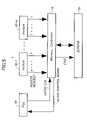
- FIG. 3is a block diagram of a memory controller to which one preferred embodiment of the clock control apparatus of the present invention is applied.
- FIG. 4is a time chart for explaining one preferred embodiment of the clock control method of the present invention.
- FIG. 5is a block diagram showing the composition of a system including the memory controller of FIG. 3 .
- FIG. 3shows the composition of a memory controller 10 to which one preferred embodiment of the clock control apparatus of the present invention is applied.
- FIG. 5shows the composition of a system including the memory controller 10 shown in FIG. 3 and an SDRAM 20 for real-time-processing applications.
- the memory controller 10 of this embodimentcomprises a system interface (SI) circuit 12 , an access-control unit 14 , and a power saving control unit 30 .
- SIsystem interface
- the access-control unit 14includes an address computation circuit 16 and a command sequence control circuit 18 .
- this system 1comprises the SDRAM 20 , the memory controller 10 , a phase-locked loop (PLL) circuit 40 , and a plurality of modules 42 - 1 , . . . , 42 -m.
- PLLphase-locked loop
- the SDRAM 20is formed as a video memory for MPEG applications etc.
- the clock control apparatus and method of the present inventionare applied to the memory controller 10 .
- the PLL circuit 40supplies the clock signal (CLK) to the SI circuit 12 ( FIG. 3 ) of the memory controller 10 .
- the PLL circuit 40receives the clock control signal (which will be described later) from the memory controller 10 .
- the PLL circuit 40controls the state (the active or inactive state) of the gate clock signal (GATED CLK) supplied to the access-control unit 14 ( FIG. 3 ) of the memory controller 10 .
- the plurality of modules 42 - 1 , . . . , 42 -m in the system 1generate the macro access to the SDRAM 20 by sending each access request (a, b, . . . , n) to the memory controller 10 .
- the macro accesswhich carries out the access request per block or per line to the plurality of banks of the SDRAM 20 is supplied to the memory controller 10 .
- the interface between the system 1 and the memory controller 10is controlled by the SI circuit 12 as shown in FIG. 3 .
- the SI circuit 12receives the macro-access requests (a, b, . . . , n) from the modules of the system 1 , and extracts the task (access block), which is going to arbitrate the access request of various kinds and is going to access it.
- the SI circuit 12supplies the command of each extracted task, which includes the head address and block size of each access block, to the address computation circuit 16 .
- the SI circuit 12supplies the command of the extracted task to the command sequence control circuit 18 .
- the address computation circuit 16 of the access-control unit 14generates the address signal, which indicates the address of the access memory location of the SDRAM 20 based on the head address and block size of the access block, and sends it out to the SDRAM 20 .
- the command sequence control circuit 18 of the access-control unit 14issues the macro command for the command sequence of each bank efficiently to the SDRAM 20 by the request of real time processing.
- the clock signal (GATED CLK) of the address computation circuit 16 and the command sequence control circuit 18 and the clock enable signal (CKE) of the SDRAM 20are controlled by the arbitration of the macro access by the SI circuit 12 , and clock control by the power-saving control circuit 30 .
- the clock signal (CLK)is always supplied to the SI circuit 12 from the PLL circuit 40 , and the SI circuit 12 operates synchronizing with this clock signal (CLK).
- the clock (GATED CLK) of the address computation circuit 16 and the command sequence control circuit 18will be suspended, and the address computation circuit 16 and the command sequence control circuit 18 will go into the inactive state.
- the SDRAM 20is set in the inactive state by control of the clock enable signal CKE sent from the power-saving control circuit 30 .
- the SDRAM 20shifts to the active state from the inactive state because the clock enable signal CKE supplied to the SDRAM 20 from the power-saving control circuit 30 shifts to the active state from the inactive state.
- the memory controller 10goes into the active state at this time.
- the address computation circuit 16 and the command sequence control circuit 18detect the end of the macro access, they will notify it to the SI circuit 12 .
- the memory controller 10shifts to the power-saving state from the active state because the SI circuit 12 controls the stop of the clock signal (GATED CLK) of the internal circuits of the memory controller, and the clock enable signal CKE of the SDRAM 20 according to this notice.
- the SI circuit 12controls the stop of the clock signal (GATED CLK) of the internal circuits of the memory controller, and the clock enable signal CKE of the SDRAM 20 according to this notice.
- FIG. 4is a time chart for explaining one preferred embodiment of the clock control method of the present invention.
- FIG. 4shows operation of the memory controller 10 when the block access request-a and the REFRESH request n input into the SI circuit 12 as a macro access from the exterior (from the plurality of modules of the system 1 ).
- the clock enable signal CKE of the initial state of the SDRAM 20 before the block access request-a occursis set in the inactive state, and the SDRAM 20 is set in the inactive state.
- the clock signal (GATED CLK) of the address computation circuit 16 in the access-control unit 14 of the memory controller 10 and the command sequence control circuit 18is in the inactive state of the clock stop.
- the inactive state of the clock stopwill be called the power-saving state, for the sake of convenience.
- both the SDRAM 20 and the internal circuits of the memory controllerare in the power-saving state (refer to FIG. 4( g )).
- the SDRAM 20is set in the active state (see FIG. 4( g )).
- the SI circuit 12sets the control signal B 1 supplied to the power-saving control circuit 30 , in the ON state.
- the power-saving control circuit 30is active in the clock enable signal CKE supplied to the SDRAM 20 —it is set as (H) (see FIG. 4( e )).
- the power-saving control circuit 30sets simultaneously the clock control signal B- 2 supplied to the PLL circuit 40 , in the ON state.
- the clock signal (GATED CLK) supplied to the access-control unit 14 from the PLL circuit 40shifts to the active state (see FIG. 4( f )).
- the SI circuit 12 and the power-saving control circuit 30carry out the control so that the internal circuits of the memory controller 10 and the SDRAM 20 to shift to the active state.
- the SI circuit 12supplies the block head address and block size of the access request-a to the address computation circuit 16 , and supplies the command of the access request-a to the command sequential circuit 18 , and the normal access operation to the SDRAM 20 is performed.
- the address computation circuit 16 and the command sequence control circuit 18detect the end of access, and set the arbitration timing signal A supplied to the SI circuit 12 in the ON state (H).
- the arbitration timing signal Ait detects whether there is a next access request of the macro access in the SI circuit 12 .
- the SI circuit 12 and the power-saving control circuit 30will start the next access operation.
- the SI circuit 12 and the power-saving control circuit 30perform control that continues the operating state as well as the control action.
- the SI circuit 12 and the power-saving control circuit 30perform control in which the internal circuit and the SDRAM 20 of the memory controller 20 are made to shift to the power-saving state from the active state.
- the SI circuit 12sets the control signal B 1 supplied to the power-saving control circuit 30 , in the OFF state.
- the power-saving control circuit 30sets the clock enable signal CKE supplied to the SDRAM 20 , in the inactive state (L) (see FIG. 4( e )).
- the power-saving control circuit 30sets simultaneously the clock control signal B- 2 supplied to the PLL circuit 40 , in the OFF state.
- the clock signal (GATED CLK) supplied to the access-control unit 14 from the PLL circuit 40is set in the inactive state ( FIG. 4( f )).
- the SI circuit 12 and the power-saving control circuit 30perform the control so that the internal circuits of the memory controller 10 and the SDRAM 20 shift to the power-saving state from the active state at this time.
- the power-saving control of the memory controller 10 to the macro accesshas been described.
- the power-saving control of the memory controller 10may be performed also to the single access similar to the case of the macro access.
- the clock control apparatus and method of the present inventionit is possible to efficiently carry out the power-saving clock control of the real-time processing SDRAM when a macro access including a sequence of several commands is given to the SDRAM by the request of the real-time processing. According to the present invention, not only the power-saving clock control of the SDRAM but also the power-saving clock control of the internal circuits of the memory controller can be realized.
Landscapes
- Engineering & Computer Science (AREA)
- Theoretical Computer Science (AREA)
- Physics & Mathematics (AREA)
- General Engineering & Computer Science (AREA)
- General Physics & Mathematics (AREA)
- Dram (AREA)
- Memory System (AREA)
Abstract
Description
Claims (8)
Applications Claiming Priority (2)
| Application Number | Priority Date | Filing Date | Title |
|---|---|---|---|
| JP2002-114295 | 2002-04-17 | ||
| JP2002114295AJP2003308246A (en) | 2002-04-17 | 2002-04-17 | Clock control device and method for memory controller |
Publications (2)
| Publication Number | Publication Date |
|---|---|
| US20030200474A1 US20030200474A1 (en) | 2003-10-23 |
| US7085941B2true US7085941B2 (en) | 2006-08-01 |
Family
ID=29207653
Family Applications (1)
| Application Number | Title | Priority Date | Filing Date |
|---|---|---|---|
| US10/414,013Expired - Fee RelatedUS7085941B2 (en) | 2002-04-17 | 2003-04-16 | Clock control apparatus and method, for a memory controller, that processes a block access into single continuous macro access while minimizing power consumption |
Country Status (2)
| Country | Link |
|---|---|
| US (1) | US7085941B2 (en) |
| JP (1) | JP2003308246A (en) |
Cited By (49)
| Publication number | Priority date | Publication date | Assignee | Title |
|---|---|---|---|---|
| US20080037353A1 (en)* | 2006-07-31 | 2008-02-14 | Metaram, Inc. | Interface circuit system and method for performing power saving operations during a command-related latency |
| US7379316B2 (en) | 2005-09-02 | 2008-05-27 | Metaram, Inc. | Methods and apparatus of stacking DRAMs |
| US7386656B2 (en) | 2006-07-31 | 2008-06-10 | Metaram, Inc. | Interface circuit system and method for performing power management operations in conjunction with only a portion of a memory circuit |
| US7392338B2 (en) | 2006-07-31 | 2008-06-24 | Metaram, Inc. | Interface circuit system and method for autonomously performing power management operations in conjunction with a plurality of memory circuits |
| US7472220B2 (en) | 2006-07-31 | 2008-12-30 | Metaram, Inc. | Interface circuit system and method for performing power management operations utilizing power management signals |
| US7515453B2 (en) | 2005-06-24 | 2009-04-07 | Metaram, Inc. | Integrated memory core and memory interface circuit |
| US20090125738A1 (en)* | 2007-11-14 | 2009-05-14 | Daisuke Murakami | Data processing apparatus |
| US7580312B2 (en) | 2006-07-31 | 2009-08-25 | Metaram, Inc. | Power saving system and method for use with a plurality of memory circuits |
| US7609567B2 (en) | 2005-06-24 | 2009-10-27 | Metaram, Inc. | System and method for simulating an aspect of a memory circuit |
| US7724589B2 (en) | 2006-07-31 | 2010-05-25 | Google Inc. | System and method for delaying a signal communicated from a system to at least one of a plurality of memory circuits |
| US8019589B2 (en) | 2006-07-31 | 2011-09-13 | Google Inc. | Memory apparatus operable to perform a power-saving operation |
| US20110264934A1 (en)* | 2010-04-26 | 2011-10-27 | Alexander Branover | Method and apparatus for memory power management |
| US8055833B2 (en) | 2006-10-05 | 2011-11-08 | Google Inc. | System and method for increasing capacity, performance, and flexibility of flash storage |
| US8060774B2 (en) | 2005-06-24 | 2011-11-15 | Google Inc. | Memory systems and memory modules |
| US8077535B2 (en) | 2006-07-31 | 2011-12-13 | Google Inc. | Memory refresh apparatus and method |
| US8081474B1 (en) | 2007-12-18 | 2011-12-20 | Google Inc. | Embossed heat spreader |
| US8080874B1 (en) | 2007-09-14 | 2011-12-20 | Google Inc. | Providing additional space between an integrated circuit and a circuit board for positioning a component therebetween |
| US8090897B2 (en) | 2006-07-31 | 2012-01-03 | Google Inc. | System and method for simulating an aspect of a memory circuit |
| US8089795B2 (en) | 2006-02-09 | 2012-01-03 | Google Inc. | Memory module with memory stack and interface with enhanced capabilities |
| US8111566B1 (en) | 2007-11-16 | 2012-02-07 | Google, Inc. | Optimal channel design for memory devices for providing a high-speed memory interface |
| US8130560B1 (en) | 2006-11-13 | 2012-03-06 | Google Inc. | Multi-rank partial width memory modules |
| US8169233B2 (en) | 2009-06-09 | 2012-05-01 | Google Inc. | Programming of DIMM termination resistance values |
| US8209479B2 (en) | 2007-07-18 | 2012-06-26 | Google Inc. | Memory circuit system and method |
| US8244971B2 (en) | 2006-07-31 | 2012-08-14 | Google Inc. | Memory circuit system and method |
| US8280714B2 (en) | 2006-07-31 | 2012-10-02 | Google Inc. | Memory circuit simulation system and method with refresh capabilities |
| US8327104B2 (en) | 2006-07-31 | 2012-12-04 | Google Inc. | Adjusting the timing of signals associated with a memory system |
| US8335894B1 (en) | 2008-07-25 | 2012-12-18 | Google Inc. | Configurable memory system with interface circuit |
| TWI382659B (en)* | 2006-09-29 | 2013-01-11 | Novatek Microelectronics Corp | Clock signal controlling devices and related methods |
| US8386722B1 (en) | 2008-06-23 | 2013-02-26 | Google Inc. | Stacked DIMM memory interface |
| US8397013B1 (en) | 2006-10-05 | 2013-03-12 | Google Inc. | Hybrid memory module |
| US8438328B2 (en) | 2008-02-21 | 2013-05-07 | Google Inc. | Emulation of abstracted DIMMs using abstracted DRAMs |
| US8566516B2 (en) | 2006-07-31 | 2013-10-22 | Google Inc. | Refresh management of memory modules |
| US8796830B1 (en) | 2006-09-01 | 2014-08-05 | Google Inc. | Stackable low-profile lead frame package |
| US8862909B2 (en) | 2011-12-02 | 2014-10-14 | Advanced Micro Devices, Inc. | System and method for determining a power estimate for an I/O controller based on monitored activity levels and adjusting power limit of processing units by comparing the power estimate with an assigned power limit for the I/O controller |
| US8924758B2 (en) | 2011-12-13 | 2014-12-30 | Advanced Micro Devices, Inc. | Method for SOC performance and power optimization |
| US8972673B2 (en) | 2006-07-31 | 2015-03-03 | Google Inc. | Power management of memory circuits by virtual memory simulation |
| US9171585B2 (en) | 2005-06-24 | 2015-10-27 | Google Inc. | Configurable memory circuit system and method |
| US9507739B2 (en) | 2005-06-24 | 2016-11-29 | Google Inc. | Configurable memory circuit system and method |
| US9542352B2 (en) | 2006-02-09 | 2017-01-10 | Google Inc. | System and method for reducing command scheduling constraints of memory circuits |
| US9632929B2 (en) | 2006-02-09 | 2017-04-25 | Google Inc. | Translating an address associated with a command communicated between a system and memory circuits |
| US10013371B2 (en) | 2005-06-24 | 2018-07-03 | Google Llc | Configurable memory circuit system and method |
| US10671148B2 (en) | 2017-12-21 | 2020-06-02 | Advanced Micro Devices, Inc. | Multi-node system low power management |
| US10955901B2 (en) | 2017-09-29 | 2021-03-23 | Advanced Micro Devices, Inc. | Saving power in the command processor using queue based watermarks |
| US11054887B2 (en) | 2017-12-28 | 2021-07-06 | Advanced Micro Devices, Inc. | System-wide low power management |
| US11100698B2 (en) | 2019-06-28 | 2021-08-24 | Ati Technologies Ulc | Real-time GPU rendering with performance guaranteed power management |
| US11435813B2 (en) | 2018-08-29 | 2022-09-06 | Advanced Micro Devices, Inc. | Neural network power management in a multi-GPU system |
| US11915359B2 (en) | 2019-12-05 | 2024-02-27 | Advanced Micro Devices, Inc. | Kernel software driven color remapping of rendered primary surfaces |
| US12153485B2 (en) | 2021-07-09 | 2024-11-26 | Ati Technologies Ulc | In-band communication interface power management fencing |
| US12416962B2 (en) | 2020-09-24 | 2025-09-16 | Advanced Micro Devices, Inc. | Mechanism for performing distributed power management of a multi-GPU system by powering down links based on previously detected idle conditions |
Families Citing this family (7)
| Publication number | Priority date | Publication date | Assignee | Title |
|---|---|---|---|---|
| JP4526841B2 (en)* | 2004-03-09 | 2010-08-18 | ルネサスエレクトロニクス株式会社 | Memory control device and data processing system having the same |
| US20120005507A1 (en)* | 2010-07-01 | 2012-01-05 | Himax Technologies Limited | Display Devices and Control Methods |
| US20120102242A1 (en)* | 2010-10-26 | 2012-04-26 | Kaminario Technologies Ltd. | Controlling data destaging within a multi-tiered storage system |
| TWI581092B (en) | 2016-03-30 | 2017-05-01 | 威盛電子股份有限公司 | Memory apparatus and energy-saving controlling method thereof |
| TWI606459B (en)* | 2016-03-30 | 2017-11-21 | 威盛電子股份有限公司 | Memory apparatus and energy-saving controlling method thereof |
| CN107564563B (en)* | 2016-06-30 | 2020-06-09 | 华邦电子股份有限公司 | Memory device and method of operating the same |
| US10754414B2 (en)* | 2017-09-12 | 2020-08-25 | Ambiq Micro, Inc. | Very low power microcontroller system |
Citations (5)
| Publication number | Priority date | Publication date | Assignee | Title |
|---|---|---|---|---|
| US5600605A (en)* | 1995-06-07 | 1997-02-04 | Micron Technology, Inc. | Auto-activate on synchronous dynamic random access memory |
| JPH09180438A (en) | 1995-12-27 | 1997-07-11 | Toshiba Corp | Memory controller |
| US6008823A (en)* | 1995-08-01 | 1999-12-28 | Rhoden; Desi | Method and apparatus for enhancing access to a shared memory |
| US6340973B1 (en)* | 1998-02-04 | 2002-01-22 | Matsushita Electric Industrial Co., Ltd. | Memory control unit and memory control method and medium containing program for realizing the same |
| US6438660B1 (en)* | 1997-12-09 | 2002-08-20 | Intel Corporation | Method and apparatus for collapsing writebacks to a memory for resource efficiency |
- 2002
- 2002-04-17JPJP2002114295Apatent/JP2003308246A/enactivePending
- 2003
- 2003-04-16USUS10/414,013patent/US7085941B2/ennot_activeExpired - Fee Related
Patent Citations (5)
| Publication number | Priority date | Publication date | Assignee | Title |
|---|---|---|---|---|
| US5600605A (en)* | 1995-06-07 | 1997-02-04 | Micron Technology, Inc. | Auto-activate on synchronous dynamic random access memory |
| US6008823A (en)* | 1995-08-01 | 1999-12-28 | Rhoden; Desi | Method and apparatus for enhancing access to a shared memory |
| JPH09180438A (en) | 1995-12-27 | 1997-07-11 | Toshiba Corp | Memory controller |
| US6438660B1 (en)* | 1997-12-09 | 2002-08-20 | Intel Corporation | Method and apparatus for collapsing writebacks to a memory for resource efficiency |
| US6340973B1 (en)* | 1998-02-04 | 2002-01-22 | Matsushita Electric Industrial Co., Ltd. | Memory control unit and memory control method and medium containing program for realizing the same |
Cited By (91)
| Publication number | Priority date | Publication date | Assignee | Title |
|---|---|---|---|---|
| US9507739B2 (en) | 2005-06-24 | 2016-11-29 | Google Inc. | Configurable memory circuit system and method |
| US7609567B2 (en) | 2005-06-24 | 2009-10-27 | Metaram, Inc. | System and method for simulating an aspect of a memory circuit |
| US8060774B2 (en) | 2005-06-24 | 2011-11-15 | Google Inc. | Memory systems and memory modules |
| US9171585B2 (en) | 2005-06-24 | 2015-10-27 | Google Inc. | Configurable memory circuit system and method |
| US8359187B2 (en) | 2005-06-24 | 2013-01-22 | Google Inc. | Simulating a different number of memory circuit devices |
| US7515453B2 (en) | 2005-06-24 | 2009-04-07 | Metaram, Inc. | Integrated memory core and memory interface circuit |
| US10013371B2 (en) | 2005-06-24 | 2018-07-03 | Google Llc | Configurable memory circuit system and method |
| US8615679B2 (en) | 2005-06-24 | 2013-12-24 | Google Inc. | Memory modules with reliability and serviceability functions |
| US8386833B2 (en) | 2005-06-24 | 2013-02-26 | Google Inc. | Memory systems and memory modules |
| US7379316B2 (en) | 2005-09-02 | 2008-05-27 | Metaram, Inc. | Methods and apparatus of stacking DRAMs |
| US8582339B2 (en) | 2005-09-02 | 2013-11-12 | Google Inc. | System including memory stacks |
| US7599205B2 (en) | 2005-09-02 | 2009-10-06 | Metaram, Inc. | Methods and apparatus of stacking DRAMs |
| US8619452B2 (en) | 2005-09-02 | 2013-12-31 | Google Inc. | Methods and apparatus of stacking DRAMs |
| US8811065B2 (en) | 2005-09-02 | 2014-08-19 | Google Inc. | Performing error detection on DRAMs |
| US8566556B2 (en) | 2006-02-09 | 2013-10-22 | Google Inc. | Memory module with memory stack and interface with enhanced capabilities |
| US9632929B2 (en) | 2006-02-09 | 2017-04-25 | Google Inc. | Translating an address associated with a command communicated between a system and memory circuits |
| US9542352B2 (en) | 2006-02-09 | 2017-01-10 | Google Inc. | System and method for reducing command scheduling constraints of memory circuits |
| US9727458B2 (en) | 2006-02-09 | 2017-08-08 | Google Inc. | Translating an address associated with a command communicated between a system and memory circuits |
| US9542353B2 (en) | 2006-02-09 | 2017-01-10 | Google Inc. | System and method for reducing command scheduling constraints of memory circuits |
| US8797779B2 (en) | 2006-02-09 | 2014-08-05 | Google Inc. | Memory module with memory stack and interface with enhanced capabilites |
| US8089795B2 (en) | 2006-02-09 | 2012-01-03 | Google Inc. | Memory module with memory stack and interface with enhanced capabilities |
| US8154935B2 (en) | 2006-07-31 | 2012-04-10 | Google Inc. | Delaying a signal communicated from a system to at least one of a plurality of memory circuits |
| US8601204B2 (en) | 2006-07-31 | 2013-12-03 | Google Inc. | Simulating a refresh operation latency |
| US8090897B2 (en) | 2006-07-31 | 2012-01-03 | Google Inc. | System and method for simulating an aspect of a memory circuit |
| US8077535B2 (en) | 2006-07-31 | 2011-12-13 | Google Inc. | Memory refresh apparatus and method |
| US8112266B2 (en) | 2006-07-31 | 2012-02-07 | Google Inc. | Apparatus for simulating an aspect of a memory circuit |
| US8745321B2 (en) | 2006-07-31 | 2014-06-03 | Google Inc. | Simulating a memory standard |
| US8041881B2 (en) | 2006-07-31 | 2011-10-18 | Google Inc. | Memory device with emulated characteristics |
| US7386656B2 (en) | 2006-07-31 | 2008-06-10 | Metaram, Inc. | Interface circuit system and method for performing power management operations in conjunction with only a portion of a memory circuit |
| US7392338B2 (en) | 2006-07-31 | 2008-06-24 | Metaram, Inc. | Interface circuit system and method for autonomously performing power management operations in conjunction with a plurality of memory circuits |
| US8019589B2 (en) | 2006-07-31 | 2011-09-13 | Google Inc. | Memory apparatus operable to perform a power-saving operation |
| US8671244B2 (en) | 2006-07-31 | 2014-03-11 | Google Inc. | Simulating a memory standard |
| US8244971B2 (en) | 2006-07-31 | 2012-08-14 | Google Inc. | Memory circuit system and method |
| US8280714B2 (en) | 2006-07-31 | 2012-10-02 | Google Inc. | Memory circuit simulation system and method with refresh capabilities |
| US8327104B2 (en) | 2006-07-31 | 2012-12-04 | Google Inc. | Adjusting the timing of signals associated with a memory system |
| US7761724B2 (en) | 2006-07-31 | 2010-07-20 | Google Inc. | Interface circuit system and method for performing power management operations in conjunction with only a portion of a memory circuit |
| US8340953B2 (en) | 2006-07-31 | 2012-12-25 | Google, Inc. | Memory circuit simulation with power saving capabilities |
| US8868829B2 (en) | 2006-07-31 | 2014-10-21 | Google Inc. | Memory circuit system and method |
| US7730338B2 (en) | 2006-07-31 | 2010-06-01 | Google Inc. | Interface circuit system and method for autonomously performing power management operations in conjunction with a plurality of memory circuits |
| US8631220B2 (en) | 2006-07-31 | 2014-01-14 | Google Inc. | Adjusting the timing of signals associated with a memory system |
| US9047976B2 (en) | 2006-07-31 | 2015-06-02 | Google Inc. | Combined signal delay and power saving for use with a plurality of memory circuits |
| US7724589B2 (en) | 2006-07-31 | 2010-05-25 | Google Inc. | System and method for delaying a signal communicated from a system to at least one of a plurality of memory circuits |
| US8972673B2 (en) | 2006-07-31 | 2015-03-03 | Google Inc. | Power management of memory circuits by virtual memory simulation |
| US7472220B2 (en) | 2006-07-31 | 2008-12-30 | Metaram, Inc. | Interface circuit system and method for performing power management operations utilizing power management signals |
| US7581127B2 (en) | 2006-07-31 | 2009-08-25 | Metaram, Inc. | Interface circuit system and method for performing power saving operations during a command-related latency |
| US8566516B2 (en) | 2006-07-31 | 2013-10-22 | Google Inc. | Refresh management of memory modules |
| US7590796B2 (en) | 2006-07-31 | 2009-09-15 | Metaram, Inc. | System and method for power management in memory systems |
| US7580312B2 (en) | 2006-07-31 | 2009-08-25 | Metaram, Inc. | Power saving system and method for use with a plurality of memory circuits |
| US8595419B2 (en) | 2006-07-31 | 2013-11-26 | Google Inc. | Memory apparatus operable to perform a power-saving operation |
| US20080037353A1 (en)* | 2006-07-31 | 2008-02-14 | Metaram, Inc. | Interface circuit system and method for performing power saving operations during a command-related latency |
| US8796830B1 (en) | 2006-09-01 | 2014-08-05 | Google Inc. | Stackable low-profile lead frame package |
| TWI382659B (en)* | 2006-09-29 | 2013-01-11 | Novatek Microelectronics Corp | Clock signal controlling devices and related methods |
| US8977806B1 (en) | 2006-10-05 | 2015-03-10 | Google Inc. | Hybrid memory module |
| US8397013B1 (en) | 2006-10-05 | 2013-03-12 | Google Inc. | Hybrid memory module |
| US8370566B2 (en) | 2006-10-05 | 2013-02-05 | Google Inc. | System and method for increasing capacity, performance, and flexibility of flash storage |
| US8055833B2 (en) | 2006-10-05 | 2011-11-08 | Google Inc. | System and method for increasing capacity, performance, and flexibility of flash storage |
| US8751732B2 (en) | 2006-10-05 | 2014-06-10 | Google Inc. | System and method for increasing capacity, performance, and flexibility of flash storage |
| US8446781B1 (en) | 2006-11-13 | 2013-05-21 | Google Inc. | Multi-rank partial width memory modules |
| US8760936B1 (en) | 2006-11-13 | 2014-06-24 | Google Inc. | Multi-rank partial width memory modules |
| US8130560B1 (en) | 2006-11-13 | 2012-03-06 | Google Inc. | Multi-rank partial width memory modules |
| US8209479B2 (en) | 2007-07-18 | 2012-06-26 | Google Inc. | Memory circuit system and method |
| US8080874B1 (en) | 2007-09-14 | 2011-12-20 | Google Inc. | Providing additional space between an integrated circuit and a circuit board for positioning a component therebetween |
| US8127161B2 (en)* | 2007-11-14 | 2012-02-28 | Panasonic Corporation | Data processing apparatus |
| US20090125738A1 (en)* | 2007-11-14 | 2009-05-14 | Daisuke Murakami | Data processing apparatus |
| US8675429B1 (en) | 2007-11-16 | 2014-03-18 | Google Inc. | Optimal channel design for memory devices for providing a high-speed memory interface |
| US8111566B1 (en) | 2007-11-16 | 2012-02-07 | Google, Inc. | Optimal channel design for memory devices for providing a high-speed memory interface |
| US8730670B1 (en) | 2007-12-18 | 2014-05-20 | Google Inc. | Embossed heat spreader |
| US8705240B1 (en) | 2007-12-18 | 2014-04-22 | Google Inc. | Embossed heat spreader |
| US8081474B1 (en) | 2007-12-18 | 2011-12-20 | Google Inc. | Embossed heat spreader |
| US8631193B2 (en) | 2008-02-21 | 2014-01-14 | Google Inc. | Emulation of abstracted DIMMS using abstracted DRAMS |
| US8438328B2 (en) | 2008-02-21 | 2013-05-07 | Google Inc. | Emulation of abstracted DIMMs using abstracted DRAMs |
| US8762675B2 (en) | 2008-06-23 | 2014-06-24 | Google Inc. | Memory system for synchronous data transmission |
| US8386722B1 (en) | 2008-06-23 | 2013-02-26 | Google Inc. | Stacked DIMM memory interface |
| US8819356B2 (en) | 2008-07-25 | 2014-08-26 | Google Inc. | Configurable multirank memory system with interface circuit |
| US8335894B1 (en) | 2008-07-25 | 2012-12-18 | Google Inc. | Configurable memory system with interface circuit |
| US8169233B2 (en) | 2009-06-09 | 2012-05-01 | Google Inc. | Programming of DIMM termination resistance values |
| US8656198B2 (en)* | 2010-04-26 | 2014-02-18 | Advanced Micro Devices | Method and apparatus for memory power management |
| US20110264934A1 (en)* | 2010-04-26 | 2011-10-27 | Alexander Branover | Method and apparatus for memory power management |
| US8862909B2 (en) | 2011-12-02 | 2014-10-14 | Advanced Micro Devices, Inc. | System and method for determining a power estimate for an I/O controller based on monitored activity levels and adjusting power limit of processing units by comparing the power estimate with an assigned power limit for the I/O controller |
| US8924758B2 (en) | 2011-12-13 | 2014-12-30 | Advanced Micro Devices, Inc. | Method for SOC performance and power optimization |
| US10955901B2 (en) | 2017-09-29 | 2021-03-23 | Advanced Micro Devices, Inc. | Saving power in the command processor using queue based watermarks |
| US10671148B2 (en) | 2017-12-21 | 2020-06-02 | Advanced Micro Devices, Inc. | Multi-node system low power management |
| US11054887B2 (en) | 2017-12-28 | 2021-07-06 | Advanced Micro Devices, Inc. | System-wide low power management |
| US12411538B2 (en) | 2017-12-28 | 2025-09-09 | Advanced Micro Devices, Inc. | System-wide low power management |
| US11435813B2 (en) | 2018-08-29 | 2022-09-06 | Advanced Micro Devices, Inc. | Neural network power management in a multi-GPU system |
| US12306694B2 (en) | 2018-08-29 | 2025-05-20 | Advanced Micro Devices, Inc. | Neural network power management in a multi-GPU system |
| US11100698B2 (en) | 2019-06-28 | 2021-08-24 | Ati Technologies Ulc | Real-time GPU rendering with performance guaranteed power management |
| US11954792B2 (en) | 2019-06-28 | 2024-04-09 | Ati Technologies Ulc | Real-time GPU rendering with performance guaranteed power management |
| US11915359B2 (en) | 2019-12-05 | 2024-02-27 | Advanced Micro Devices, Inc. | Kernel software driven color remapping of rendered primary surfaces |
| US12416962B2 (en) | 2020-09-24 | 2025-09-16 | Advanced Micro Devices, Inc. | Mechanism for performing distributed power management of a multi-GPU system by powering down links based on previously detected idle conditions |
| US12153485B2 (en) | 2021-07-09 | 2024-11-26 | Ati Technologies Ulc | In-band communication interface power management fencing |
Also Published As
| Publication number | Publication date |
|---|---|
| US20030200474A1 (en) | 2003-10-23 |
| JP2003308246A (en) | 2003-10-31 |
Similar Documents
| Publication | Publication Date | Title |
|---|---|---|
| US7085941B2 (en) | Clock control apparatus and method, for a memory controller, that processes a block access into single continuous macro access while minimizing power consumption | |
| US6457095B1 (en) | Method and apparatus for synchronizing dynamic random access memory exiting from a low power state | |
| US6657634B1 (en) | Dynamic graphics and/or video memory power reducing circuit and method | |
| US6263448B1 (en) | Power control system for synchronous memory device | |
| JP3969547B2 (en) | Semiconductor memory device and memory system using the same | |
| US6795906B2 (en) | Memory controller, interface device and method using a mode selection signal to support different types of memories | |
| EP1581856B1 (en) | Memory controller considering processor power states | |
| US7430143B2 (en) | Delay locked operation in semiconductor memory device | |
| US5901101A (en) | Semiconductor memory device | |
| US7752373B2 (en) | System and method for controlling memory operations | |
| US5881016A (en) | Method and apparatus for optimizing power consumption and memory bandwidth in a video controller using SGRAM and SDRAM power reduction modes | |
| US6848058B1 (en) | Power reduction circuit and method with multi clock branch control | |
| JPH07210129A (en) | Self-timing real-time data transfer in video ram | |
| CN103632708B (en) | The self refresh control apparatus of synchronous DRAM and method | |
| US6990599B2 (en) | Method and apparatus of clock control associated with read latency for a card device | |
| US6545941B2 (en) | Clock synchronous circuit | |
| JP2011146043A (en) | Semiconductor device, semiconductor system having the device, and method of operating the system | |
| JPH0844559A (en) | Data processor and its operating method | |
| JP2000163962A (en) | Clock synchronization system | |
| US5893158A (en) | Multibank dram system controlled by multiple dram controllers with an active bank detector | |
| US7437592B2 (en) | Information processing device using variable operation frequency | |
| KR20050086525A (en) | Information storage device, information storage method, and information storage program | |
| CN1937075B (en) | Data transfer operation completion detection circuit and semiconductor memory device provided therewith | |
| US7463538B2 (en) | Semiconductor memory device having a precharge control circuit for reducing current during continuous write operation | |
| US6055609A (en) | Apparatus and method for improving bus usage in a system having a shared memory |
Legal Events
| Date | Code | Title | Description |
|---|---|---|---|
| AS | Assignment | Owner name:FUJITSU LIMITED, JAPAN Free format text:ASSIGNMENT OF ASSIGNORS INTEREST;ASSIGNOR:LI, JIANG;REEL/FRAME:013970/0930 Effective date:20030408 | |
| AS | Assignment | Owner name:FUJITSU LIMITED, JAPAN Free format text:CORRECTED ASSIGNMENT TO CORRECT THE ASSIGNEE'S ADDRESS. PREVIOUSLY RECORDED ON REEL 013970 FRAME 0930.;ASSIGNOR:LI, JIANG;REEL/FRAME:014530/0726 Effective date:20030408 | |
| FEPP | Fee payment procedure | Free format text:PAYOR NUMBER ASSIGNED (ORIGINAL EVENT CODE: ASPN); ENTITY STATUS OF PATENT OWNER: LARGE ENTITY | |
| FPAY | Fee payment | Year of fee payment:4 | |
| FPAY | Fee payment | Year of fee payment:8 | |
| FEPP | Fee payment procedure | Free format text:MAINTENANCE FEE REMINDER MAILED (ORIGINAL EVENT CODE: REM.) | |
| LAPS | Lapse for failure to pay maintenance fees | Free format text:PATENT EXPIRED FOR FAILURE TO PAY MAINTENANCE FEES (ORIGINAL EVENT CODE: EXP.); ENTITY STATUS OF PATENT OWNER: LARGE ENTITY | |
| STCH | Information on status: patent discontinuation | Free format text:PATENT EXPIRED DUE TO NONPAYMENT OF MAINTENANCE FEES UNDER 37 CFR 1.362 | |
| FP | Lapsed due to failure to pay maintenance fee | Effective date:20180801 |