US7085814B1 - Data driven remote device control model with general programming interface-to-network messaging adapter - Google Patents
Data driven remote device control model with general programming interface-to-network messaging adapterDownload PDFInfo
- Publication number
- US7085814B1 US7085814B1US09/706,446US70644600AUS7085814B1US 7085814 B1US7085814 B1US 7085814B1US 70644600 AUS70644600 AUS 70644600AUS 7085814 B1US7085814 B1US 7085814B1
- Authority
- US
- United States
- Prior art keywords
- service
- upnp
- action
- control
- devices
- Prior art date
- Legal status (The legal status is an assumption and is not a legal conclusion. Google has not performed a legal analysis and makes no representation as to the accuracy of the status listed.)
- Expired - Lifetime, expires
Links
Images


Classifications
- H—ELECTRICITY
- H04—ELECTRIC COMMUNICATION TECHNIQUE
- H04L—TRANSMISSION OF DIGITAL INFORMATION, e.g. TELEGRAPHIC COMMUNICATION
- H04L12/00—Data switching networks
- H04L12/28—Data switching networks characterised by path configuration, e.g. LAN [Local Area Networks] or WAN [Wide Area Networks]
- H04L12/2803—Home automation networks
- H04L12/2807—Exchanging configuration information on appliance services in a home automation network
- H04L12/281—Exchanging configuration information on appliance services in a home automation network indicating a format for calling an appliance service function in a home automation network
- H—ELECTRICITY
- H04—ELECTRIC COMMUNICATION TECHNIQUE
- H04L—TRANSMISSION OF DIGITAL INFORMATION, e.g. TELEGRAPHIC COMMUNICATION
- H04L12/00—Data switching networks
- H04L12/28—Data switching networks characterised by path configuration, e.g. LAN [Local Area Networks] or WAN [Wide Area Networks]
- H04L12/46—Interconnection of networks
- H04L12/4633—Interconnection of networks using encapsulation techniques, e.g. tunneling
- H—ELECTRICITY
- H04—ELECTRIC COMMUNICATION TECHNIQUE
- H04L—TRANSMISSION OF DIGITAL INFORMATION, e.g. TELEGRAPHIC COMMUNICATION
- H04L47/00—Traffic control in data switching networks
- H04L47/10—Flow control; Congestion control
- H04L47/24—Traffic characterised by specific attributes, e.g. priority or QoS
- H04L47/2408—Traffic characterised by specific attributes, e.g. priority or QoS for supporting different services, e.g. a differentiated services [DiffServ] type of service
- H—ELECTRICITY
- H04—ELECTRIC COMMUNICATION TECHNIQUE
- H04L—TRANSMISSION OF DIGITAL INFORMATION, e.g. TELEGRAPHIC COMMUNICATION
- H04L61/00—Network arrangements, protocols or services for addressing or naming
- H04L61/30—Managing network names, e.g. use of aliases or nicknames
- H—ELECTRICITY
- H04—ELECTRIC COMMUNICATION TECHNIQUE
- H04L—TRANSMISSION OF DIGITAL INFORMATION, e.g. TELEGRAPHIC COMMUNICATION
- H04L61/00—Network arrangements, protocols or services for addressing or naming
- H04L61/50—Address allocation
- H04L61/5007—Internet protocol [IP] addresses
- H04L61/5014—Internet protocol [IP] addresses using dynamic host configuration protocol [DHCP] or bootstrap protocol [BOOTP]
- H—ELECTRICITY
- H04—ELECTRIC COMMUNICATION TECHNIQUE
- H04L—TRANSMISSION OF DIGITAL INFORMATION, e.g. TELEGRAPHIC COMMUNICATION
- H04L61/00—Network arrangements, protocols or services for addressing or naming
- H04L61/50—Address allocation
- H04L61/5092—Address allocation by self-assignment, e.g. picking addresses at random and testing if they are already in use
- H—ELECTRICITY
- H04—ELECTRIC COMMUNICATION TECHNIQUE
- H04L—TRANSMISSION OF DIGITAL INFORMATION, e.g. TELEGRAPHIC COMMUNICATION
- H04L67/00—Network arrangements or protocols for supporting network services or applications
- H04L67/01—Protocols
- H04L67/02—Protocols based on web technology, e.g. hypertext transfer protocol [HTTP]
- H—ELECTRICITY
- H04—ELECTRIC COMMUNICATION TECHNIQUE
- H04L—TRANSMISSION OF DIGITAL INFORMATION, e.g. TELEGRAPHIC COMMUNICATION
- H04L67/00—Network arrangements or protocols for supporting network services or applications
- H04L67/01—Protocols
- H04L67/12—Protocols specially adapted for proprietary or special-purpose networking environments, e.g. medical networks, sensor networks, networks in vehicles or remote metering networks
- H04L67/125—Protocols specially adapted for proprietary or special-purpose networking environments, e.g. medical networks, sensor networks, networks in vehicles or remote metering networks involving control of end-device applications over a network
- H—ELECTRICITY
- H04—ELECTRIC COMMUNICATION TECHNIQUE
- H04L—TRANSMISSION OF DIGITAL INFORMATION, e.g. TELEGRAPHIC COMMUNICATION
- H04L67/00—Network arrangements or protocols for supporting network services or applications
- H04L67/14—Session management
- H—ELECTRICITY
- H04—ELECTRIC COMMUNICATION TECHNIQUE
- H04L—TRANSMISSION OF DIGITAL INFORMATION, e.g. TELEGRAPHIC COMMUNICATION
- H04L67/00—Network arrangements or protocols for supporting network services or applications
- H04L67/50—Network services
- H04L67/51—Discovery or management thereof, e.g. service location protocol [SLP] or web services
- H—ELECTRICITY
- H04—ELECTRIC COMMUNICATION TECHNIQUE
- H04L—TRANSMISSION OF DIGITAL INFORMATION, e.g. TELEGRAPHIC COMMUNICATION
- H04L9/00—Cryptographic mechanisms or cryptographic arrangements for secret or secure communications; Network security protocols
- H04L9/40—Network security protocols
- H—ELECTRICITY
- H04—ELECTRIC COMMUNICATION TECHNIQUE
- H04L—TRANSMISSION OF DIGITAL INFORMATION, e.g. TELEGRAPHIC COMMUNICATION
- H04L12/00—Data switching networks
- H04L12/28—Data switching networks characterised by path configuration, e.g. LAN [Local Area Networks] or WAN [Wide Area Networks]
- H04L12/2803—Home automation networks
- H04L12/2816—Controlling appliance services of a home automation network by calling their functionalities
- H04L12/282—Controlling appliance services of a home automation network by calling their functionalities based on user interaction within the home
- H—ELECTRICITY
- H04—ELECTRIC COMMUNICATION TECHNIQUE
- H04L—TRANSMISSION OF DIGITAL INFORMATION, e.g. TELEGRAPHIC COMMUNICATION
- H04L12/00—Data switching networks
- H04L12/28—Data switching networks characterised by path configuration, e.g. LAN [Local Area Networks] or WAN [Wide Area Networks]
- H04L12/2803—Home automation networks
- H04L2012/2847—Home automation networks characterised by the type of home appliance used
- H04L2012/2849—Audio/video appliances
- H—ELECTRICITY
- H04—ELECTRIC COMMUNICATION TECHNIQUE
- H04L—TRANSMISSION OF DIGITAL INFORMATION, e.g. TELEGRAPHIC COMMUNICATION
- H04L2101/00—Indexing scheme associated with group H04L61/00
- H04L2101/30—Types of network names
- H04L2101/365—Application layer names, e.g. buddy names, unstructured names chosen by a user or home appliance name
- H—ELECTRICITY
- H04—ELECTRIC COMMUNICATION TECHNIQUE
- H04L—TRANSMISSION OF DIGITAL INFORMATION, e.g. TELEGRAPHIC COMMUNICATION
- H04L67/00—Network arrangements or protocols for supporting network services or applications
- H—ELECTRICITY
- H04—ELECTRIC COMMUNICATION TECHNIQUE
- H04L—TRANSMISSION OF DIGITAL INFORMATION, e.g. TELEGRAPHIC COMMUNICATION
- H04L67/00—Network arrangements or protocols for supporting network services or applications
- H04L67/01—Protocols
- H04L67/02—Protocols based on web technology, e.g. hypertext transfer protocol [HTTP]
- H04L67/025—Protocols based on web technology, e.g. hypertext transfer protocol [HTTP] for remote control or remote monitoring of applications
- H—ELECTRICITY
- H04—ELECTRIC COMMUNICATION TECHNIQUE
- H04L—TRANSMISSION OF DIGITAL INFORMATION, e.g. TELEGRAPHIC COMMUNICATION
- H04L69/00—Network arrangements, protocols or services independent of the application payload and not provided for in the other groups of this subclass
- H04L69/30—Definitions, standards or architectural aspects of layered protocol stacks
- H04L69/32—Architecture of open systems interconnection [OSI] 7-layer type protocol stacks, e.g. the interfaces between the data link level and the physical level
- H04L69/322—Intralayer communication protocols among peer entities or protocol data unit [PDU] definitions
- H04L69/329—Intralayer communication protocols among peer entities or protocol data unit [PDU] definitions in the application layer [OSI layer 7]
Definitions
- This inventionrelates generally to dynamic configuration of interconnectivity among distributed devices and services, and more particularly relates to providing a capability to access device- or service-specific operational information and perform remote automation and control of embedded computing devices using a data-driven remote programming model, such as in a pervasive computing environment
- the cost of computing and networking technologieshave fallen to the point where computing and networking capabilities can be built into the design of many electronic devices in the home, the office and public places.
- the combination of inexpensive and reliable shared networking media with a new class of small computing deviceshas created an opportunity for new functionality based mainly on the connectivity among these devices.
- This connectivitycan be used to remotely control devices, to move digital data in the form of audio, video and still images between devices, to share information among devices and with the unconstrained World Wide Web of the Internet (hereafter “Web”) and to exchange structured and secure digital data to support things like electronic commerce.
- WebWorld Wide Web of the Internet
- the connectivityalso enables many new applications for computing devices, such as proximity-based usage scenarios where devices interact based at least in part on geographical or other notions of proximity.
- a prevalent feature of these connectivity scenariosis to provide remote access and control of connected devices and services from another device with user interface capabilities (e.g., a universal remote controller, handheld computer or digital assistant, cell phones, and the like).
- user interface capabilitiese.g., a universal remote controller, handheld computer or digital assistant, cell phones, and the like.
- Prior connectivity modelsare not adequate to bridge between object interfaces and the data messages exchanged with the controlled device over a network.
- Some prior connectivity modelsrequire a controlling device to download the program code (such as a device driver, Jini code, etc.) for interacting with the controlled device or service from a networked source. Such a code download requirement is unsuitable to the Web and other ubiquitous computing scenarios.
- Other connectivity modelsrequire use of a custom-written object for specific classes of services. This approach leads to deployment hassles (e.g., user setup and configuration) and also is unsuitable to ubiquitous computing.
- a general programmatic interface-to-network messaging adapter(called a “rehydrator”) is a module that exposes a suitable object integration interface or application programming interface to applications on a controller device and sends network data messages to invoke services or query status of a controlled device.
- the adaptermaps application calls to the interface into network data messages according to service protocols of the controlled device.
- the described adapterpreferably is generic to all devices and services compatible with the connectivity model, and adapts itself to specific of the devices based on a Service Description.
- this adapteroperates as a universal module through which network data message-driven services on other networked computing devices can remote programmatic application programming interfaces, including object integration interfaces according to an object model such as Microsoft's COM, CORBA, JAVA, and the like.
- this general adapterprovides the interface suitable to any specific service of a controlled device based on a data description of the interface, and converts the application calls to network data messages based on a data description of network data messages to interact with the specific service.
- Service DescriptionOnce the Service Description is obtained, applications on the controller device can programmatically interact with the adapter, and the adapter then handles appropriate message exchanges with the service of the controlled device.
- no code downloadis required, only the interface/messaging description is needed.
- the descriptioncan be obtained from the controlled device, a network server computer, or by pre-loading or caching on the controller device.
- the technologyallows controller device applications to be written using object-oriented programming, while avoiding code download.
- FIGS. 1 and 2are block diagrams of a device architecture per Universal Plug and Play using Control Points, controlled devices and bridges for connectivity between devices.
- FIG. 3is a block diagram of a device model per Universal Plug and Play.
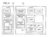
- FIG. 4is a block diagram illustrating example devices conforming to the device model of FIG. 3 .
- FIG. 5is a block diagram illustrating device state synchronization using a state table and eventing.
- FIG. 6is a block diagram illustrating device addressing.
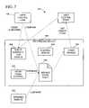
- FIG. 7is a block diagram of a programmatic interface-to-network messaging adapter or Rehydrator in the device control model of FIG. 3 .
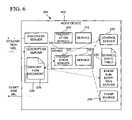
- FIG. 8is a general data flow diagram of the Rehydrator of FIG. 7 in the device control model of FIG. 3 .
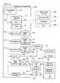
- FIG. 9is a block diagram of an implementation design of the Rehydrator of FIG. 7 .
- FIGS. 10 and 11are block diagrams illustrating an internal software architecture of the Control Point and controlled device in the device control model of FIG. 3 .
- FIG. 12is a block diagram illustrating an internal software architecture of a combined bridge and Control Point in the device control model of FIG. 3 .
- FIG. 13is a data flow diagram illustrating a typical browsing protocol sequence in the device control model of FIG. 3 .
- FIG. 14is a listing showing a layout of a description document in the device control model of FIG. 3 .
- FIG. 15is a listing of an exemplary icon list of a Description Document in the device control model of FIG. 3 .
- FIG. 16is a listing of an exemplary Service Description in a Description Document in the device control model of FIG. 3 .
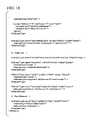
- FIGS. 17 and 18are a listing of an XML schema for a Service Description Language used in the device control model of FIG. 3 .
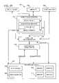
- FIG. 19is a block diagram of an eventing model used in the device control model of FIG. 3 .
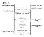
- FIG. 20is a data flow diagram illustrating subscription, notification and unsubscription in the eventing model of FIG. 19 .
- FIG. 21is a block diagram of a computer system that may be used in the device control model of FIG. 3 .
- FIG. 22is a block diagram of a device having embedded computing and networking capability per universal-plug-and-play (UPNP) standards that may be used in combination with the computer system of FIG. 21 in the device control model of FIG. 3 .
- UPNPuniversal-plug-and-play
- FIG. 23is a block diagram of a software architecture per UPNP standards in the embedded computing device of FIG. 22
- FIG. 24is a data flow diagram of a process for automatic network introduction of the embedded computing device of FIG. 22 into an ad hoc computer network environment per the UPNP protocol.
- FIG. 25is a data flow diagram of a process for automatic network introduction of the embedded computing device of FIG. 22 into a configured computer network environment per the UPNP protocol.
- FIG. 26is a block diagram of a software architecture of a client device per UPNP standards having embedded computing and networking capability that may be used in the device control model of FIG. 3 .
- FIG. 27is a block diagram of an exemplary home or office pervasive computing environment having a variety of computers as per FIG. 21 and embedded computing devices as per FIG. 22 interconnected per UPNP standards that may be used in the device control model of FIG. 3 .
- FIGS. 28 through 40are program listings of interfaces used in the Rehydrator implementation design of FIG. 9 .
- a general programmatic interface-to-network messaging adapteralso known as a “rehydrator” in a device control model.
- the rehydratoris used in a device architecture 100 ( FIG. 1 ) of a pervasive peer-to-peer networking connectivity protocol proposed by Microsoft Corporation, called Universal Plug and Play (“UPnP”), which is discussed in more detail in the Appendix section below entitled, “Universal Plug and Play Device Architecture.”
- UPPUniversal Plug and Play
- the general programmatic interface-to-network messaging adapter of the inventionalso is more generally applicable in other distributed networking environments to provide an object-oriented or like application programming interface to applications for interacting remotely using network data messages.
- UPnPprovides a device-driven auto-configuration capability that preserves the experience that customers have on the web.
- Todayit is possible to navigate around the web without loading programs beyond the browser itself.
- UPnPenables the browser to be extended to control devices, and because UPnP devices are controlled with explicit protocols, the browser must somehow learn how to talk to UPnP devices. This learning process is driven entirely from the device itself and is accomplishing entirely by uploading an XML document that describes the capabilities of the device.
- the architectural component that enables device-driven auto-configurationis called the Rehydrator.
- the job of the Rehydratoris to convert between APIs and protocols.
- UPnPenables programmatic control in addition to browser control of devices. This is achieved simply by enabling applications to call the same Rehydrator APIs that the browser does. Applications can also directly generate and consume the raw UPnP control protocols, provided they are not interested in the device-driven auto-configuration enabled by the Rehydrator.
- UPnPassumes that there will be more than one device with UI that wants to control other devices in any given network, and it provides a simple mechanism that enables these Control Points to remain in sync. This mechanism can easily support device front panels and wireless remotes that do not run UPnP protocols.
- the UPnP control modelis third-party control; any device can transfer bulk data (e.g. files) or A/V data streams from any device on the network, to any device on the network, under the control of any device on the network.
- UPnPis an application-level distributed network architecture where the logical nodes on the network are Control Points 104 – 105 , Controlled Devices 106 – 107 and Bridges 120 . These classifications refer to functionality rather than physical entities. The functionality of UPnP Control Points 104 – 105 , Controlled Devices 106 – 107 and Bridges 120 can be packaged into physical entities (e.g., multiple function devices 102 – 103 ) in any combination.
- a Control Pointis a set of modules that enable communication with a UPnP Controlled Device.
- a moduleis a component of a device, software program, or system that implements some “functionality”, which can be embodied as software, hardware, firmware, electronic circuitry, or etc.
- Control Pointsinitiate discovery and communication with Controlled Devices, and receive Events from Controlled Devices.
- Control Pointsare typically implemented on devices that have a user interface. This user interface is used to interact with Controlled Devices over the network.
- the modulesminimally include a Discovery Client, a Description Client and a Rehydrator. Control Points may also include Visual Navigation, an Event Subscription Client, Event Sink, a web browser and an application execution environment.
- Control Pointscan add value to the network by aggregating the control of multiple Controlled Devices (the universal remote) or they can implement a function as simple as initiating the transfer of data to or from a Controlled Device.
- Examples of devices that could be Control Pointsare the personal computer (PC), digital television (DTV), set-top box (STB), handheld computer and smart mobile phone, and the like. None prevents a single device from implementing the functionality of a Control Point and one or more Controlled Devices at the same time.
- a Controlled Deviceis a set of modules that enable communication with a Control Point. Controlled Devices respond to discovery requests, accept incoming communications from Control Points and may send Events to Control Points. Devices that support Controlled Device functionality may also support local user interfaces such as front panel displays or wireless remotes.
- the modulesminimally include a Discovery Server, a Description Server and a Control Server. Controlled Devices may also include a Presentation (web) Server, Event Subscription Server and Event Source. Examples of devices that could be Controlled Devices are the VCR, DVD player or recorder, heating/ventilation/air-conditioning equipment (HVAC), lighting controller, audio/video/imaging playback device, handheld computer, smart mobile phone and the PC, and the like. None prevents a single device from implementing the functionality of a Control Point and one or more Controlled Devices at the same time.
- HVACheating/ventilation/air-conditioning equipment
- a Bridgeis a set of modules that enables Bridged and Legacy Devices to interact with native UPnP devices.
- the bridgeitself exposes a collection of UPnP Controlled Devices to Control Points.
- the Bridgemaps between native UPnP Device Control Protocols and the underlying protocols exposed by the Bridged and Legacy Devices.
- such a devicecould expose UPnP Controlled Devices to Legacy Devices in the manner required by the Legacy Devices.
- Bridges 120( FIG. 2 ) expose devices that do not expose native UPnP protocols as native UPnP Controlled Devices.
- the Bridgeitself looks to other UPnP Control Points like a set of Controlled Devices.
- the Bridged Deviceis a device that cannot participate in UPnP at the native protocol level, either because the device does not have sufficient resources or because the underlying media is unsuitable to run TCP and HTTP.
- Examples of devices that could be Bridged Devicesare power line-controlled A/V equipment, light switches, thermostats, wristwatches and inexpensive toys.
- Bridged Devicesare UPnP complaint and are exposed to other UPnP devices through a UPnP Bridge.
- the Legacy Deviceis any non-UPnP compliant device that must be exposed to other UPnP devices through a UPnP Bridge.
- Control Point 104 – 105The primary distinction between a Control Point 104 – 105 and a Controlled Device 106 – 107 is that the Control Point is always the communication initiator of control operations (for discovery, the Controlled Device may be the initiator). After the initial communication, Control Points can receive events from Controlled Devices.
- Controlled Devices 106 – 107are responsible for storing the state of Services. Control Points are required to synchronize to the state on Controlled Devices.
- Control Pointstypically have user interface that is used to access one or more Controlled Devices on the network. Controlled Devices only have local user interfaces.
- Control Points 104 – 105The following table lists the modules in the Control Points 104 – 105 and Controlled Devices 106 – 107 , along with their functions.
- Control Point Controlled Device Function Module Function ModuleInitiate discovery of Discovery Client Respond to Discovery Controlled Devices.
- discovery Serverrequests. Retrieve Device Description Client Provide Device Description Descriptions. Descriptions. Server Display a folder of Visual Navigation icons per discovered Device and allow transfer of control to a selected device. View user interface Web Browser Provide user Presentation exposed by a inteface for (Web) Controlled Device. remote Control Server Points.
- Execute Application applicationsExecution Environment Invoke Actions on a Rehydrator Accept incom- Control Ser- Controlled Device ing Actions in ver plus na- by sending Service SCPs and tive control Control Protocols in execute them. logic response to local API calls. Inform a Controlled Event Subscription Accept requests Event Sub- Device of a desire to Client for Events and scription receive Events. remember Server them. Receive an Event. Event Sink Send an Event.
- Event Sourcea folder of Visual Navigation icons per discovered Device and allow transfer of control to a selected device. View user interface Web Browser Provide user Presentation exposed by a inteface for (Web) Controlled Device. remote Control
- the UPnP Device Model 200 shown in FIG. 3is the model of a UPnP Controlled Device or Bridge that is emulating native Controlled Devices.
- the Device Modelincludes the addressing scheme, eventing scheme, Device Description schema, Devices and Services schema and hierarchy, and the functional description of modules.
- the UPnP Device Modelextends beyond simple API or a command and control protocol descriptions to enable multiple Control Points to have a consistent view of Controlled Devices. This requires that the state of running services be formally modeled and that all state changes be visible to Control Points.
- Central to the distributed UPnP architectureis the rule that Controlled Devices are the ultimate authority for the state of Services running on them.
- the fundamental controllable entity in UPnPis a Service 210 – 217 .
- An example of a Serviceis “Clock”.
- Servicesare defined with a mandatory common base set of functionality. Vendors can extend the base set with proprietary extensions provided the base functionality is implemented.
- Service Descriptionsare versioned and later versions are constrained to be supersets of previous versions.
- UPnPenables searches for all Devices that contain a specified Service of a minimum version. This search would find all clocks, regardless of their packaging. A search for Device Type “Clock” would be used to find only stand-alone clocks.
- Every running instance of a Serviceincludes:
- the formal definition of a Serviceincludes:
- a UPnP Device 202 – 205(e.g., multiple function devices 102 – 103 of FIG. 1 and bridged devices 122 – 123 of FIG. 2 ) is a logical container of one or more Services 210 – 217 .
- a Devicerepresents a physical entity such as a VCR.
- Typical Services in the VCR Device examplemight be “TRANSPORT”, “TUNER”, “TIMER” and “CLOCK”. While Devices are often physical entities, a PC emulating the traditional functions of a VCR could also be modeled in the same way as the stand-alone VCR. Devices can contain other Devices.
- An examplewould be a TV/VCR 250 ( FIG.
- a Device(e.g., devices 202 – 203 ) may also be a logical container of other Devices.
- the top-most Device in a hierarchy of nested Devices 203 – 205is called the Root Device 202 .
- a Device with no nested Devicesis always a Root Device.
- the UPnP Device Modelwas designed to be general and flexible. It should be possible to model an entire Nuclear Power Plant as a single Service or as a deeply nested hierarchy of Devices and Services.
- a Service 210 – 217is cohesive set of functions that enables flexible packaging into a variety of Devices. Services can be versioned independently of Devices.
- All Devices, including Root Devicesbelong to one or more Device Types.
- Device Typesare intended to enable instances of Devices to be simply and automatically grouped for presentation.
- An example of a Device Typeis “VCR” 254 ( FIG. 4 ).
- Device Typesare formally defined in terms of a minimal set of versioned Services that a Device of Device Type must support. Device Types are not formally versioned. Device Type is a relatively high level grouping. A Device of Device Type only ensures that minimal set of Services of a minimal version is present. There can be other Services, higher versioned Services and Services with vendor extensions present on such a Device.
- UPnPenables SSDP level searches for a unique instance of a Device (by UDN), all Devices of type Device Type and all Devices that contain at least one Service Type of minimum version.
- the result of an SSDP searchis always a URL that points to the Device Description contained in the Root Device.
- the Device Descriptionhas a tree of nested Devices that can be traversed to find the matching Device.
- Every Deviceincludes:
- the Root Device 202includes a Discovery Server 208 , which is a module that runs in a Controlled Device or Bridge that responds to SSDP queries. This Server is unique in that it must support UDP/HTTP rather than just TCP/HTTP.
- Every Root Device 202also includes the Device Description 226 and Description Server 228 for all Devices under and including itself.
- the Device Descriptionis a structured unit of data that is used by a Control Point or UPnP Bridge to learn the capabilities of a Controlled Device. Device Descriptions are retrieved from the Description Server on a UPnP Controlled Device. There is one Device Description for every Root Device that describes the Root Device and all non-Root Devices. Device Descriptions adhere to XML grammar. To support localization, multiple Device Descriptions can exist.
- a Control Pointrequests the preferred localized Device Description by using the standard HTTP “accept-language” header.
- the Description Serveris a module that runs in a Controlled Device or Bridge that responds to HTTP GETs and returns Device Descriptions. This service consists of a TCP/HTTP server than can retrieve and return a Device Description from persistent storage (like a filesystem).
- the formal definition of a Deviceincludes:
- the formal definition of a Device Typeincludes:
- a Service State Table(SST) logically consists of rows of:
- entries of the Service State Table in UPnPconsist of these five items, the state table alternatively can contain fewer or additional items. Generally, each entry will minimally consist of a Variable name or identifier, and its current value.
- An SSTcan be used to represent to current operational mode of device, act as an information source or sink and/or simply be a repository for Actions.
- the SST of a VCR Servicecould represent the current transport mode, tuner channel selection, input and output switch selections, audio and video decoding format and current timer program.
- the VCR 254could be represented as a Transport Service 260 , Tuner Service, I/O Switch Service, A/V Decoding Configuration Service and Programmable Timer Service 261 .
- the SST of a clock 251would likely represent the current time. Additionally an alarm clock could include Service Variables to configure the clock.
- the SST of an image rendering devicecould implement a video frame-buffer that can accept raw pixel information or formatted JPG files.
- the SST of an audio or video playback devicecould implement a transfer buffer or queue of material to be played.
- the SST of PDAcould implement a collection of formatted data that has changed and needed to be synchronized with another device, in addition to a transfer buffer for accepting incoming formatted data.
- UPnP rulesrequire that every change to an evented variable in an SST generate a corresponding event to announce the change to the all interested Control Points.
- An eventis an unsolicited message generated by a Controlled Device and delivered to one or more Control Points. Events are used to maintain a consistent view of the state of Service across all interested Control Points. UPnP leverages the GENA event architecture (see “Generic Event Notification”) to transport event messages. All events are delivered using TCP/IP for reliability.
- URLsare a format for expressing web addresses. URLs minimally contain an identification of the protocol family that the URL is valid for, a Hostname, and a path. UPnP uses URLs as addresses whenever the module accepting the incoming connection is an HTTP server. URLs minimally contain an identification of the application protocol family (“http”) that the URL is valid for, a Hostname and a path. In the context of UPnP, the path part of a URL can represent either a filesystem path or simply an identifier of the local system module and context that can process incoming messages.
- httpapplication protocol family
- a Hostnameis the Domain Name System (DNS) or NetBIOS Name Service (NBNS) that, when resolved to an IP address, represents a network interface that can be used to establish TCP/IP level connectivity to Control Points, Controlled Devices or Bridges.
- Hostnamescan be used to provide persistent network level addressing on a network where IP addresses are dynamically assigned and of unknown lifespan or to integrate with an existing managed network.
- UPnPprovides an algorithm for seeding a device's hostname from its UDN at manufacturing time.
- the HTTP Serveris a module that accepts incoming TCP/HTTP connections and either returns a web page or forwards the payload data to another module.
- Client and Serverdescribe only the direction of initiation of TCP/HTTP connections.
- Control PointsThere is no relationship between the low level concepts of Client and Server and the high level concepts of Control Point and Controlled Devices. Logically, Control Points always discover and initiate communication with Controlled Devices, but this communication requires Client and Server functionality on both sides. In most cases, the job of the HTTP server is simply to accept the incoming connection, look at the local destination part of the address (the path) and forward the payload to another module.
- UPnPenables, but does not require, that all HTTP Servers be based on a common software implementation or runtime instance.
- Controlled Devices and Bridgescan include a TCP port specification as part of a URL to override the default value of 80.
- the successful result of a UPnP SSDP level searchis always one or more Description URLs. These URLs can be used to navigate to the Device Description of a Controlled Device or Bridge. This URL always points to a Description Server on the Controlled Device. An HTTP GET can be issued on this URL to retrieve the Device Description. This URL is valid as an address for the lifetime of the Hostname embedded in the URL. A Control Point uploads the Device Description and extracts the URLs of the Servers running on the Controlled Device or Bridge.
- the lifetime of a Description URLis determined by Controlled Device or Bridge that advertises it. If a Controlled Device or Bridge allows an SSDP advertisement of a Description URL to expire, the URL is invalidated.
- Control Pointsuse the Event Subscription URL returned by the Controlled Device or Bridge to connect to the Event Subscription Server.
- This serverdoes the housekeeping of remembering all Control Points that are interested in receiving Events on a Service.
- the Event Subscription Serverneeds an address to send the events back to. This address is called the Event Sink URL, and is supplied to the Controlled Device or Bridge in the GENA SUBSCRIBE message.
- the lifetime of an event subscription, and the Event Sink URLis determined by the timeout on the SUBSCRIBE message.
- This URLis returned by the Description Server as part of the discovery process.
- This URLis returned in the Device Description.
- UPnPenables SSDP searches for a unique Root or non-Root Device by UDN, devices of a specified Device Type and devices containing a Service of a specified Service Type. UPnP also supports a search for all Root devices.
- a unique RootA single Description URL pointing to the Description Device (by UDN) Server and Document path on the Root Device.
- a unique non- A single Description URL pointing to the Description Root Devicecontains the non-Root Device.
- Type of DeviceA set of Description URLs pointing to the Description Servers/Document paths of all Root Devices that match the Device Type, or contain a non-Root Device that matches the Device Type.
- Type of ServiceA set of Description URLs pointing to the Description Servers/Document paths of all Root Devices that contain a matching Service, or contain a non-Root Device that contains a matching Service.
- SSDPspecifies Service Type (ST), Notification type (NT), and Unique Service Name (USN) header fields for queries and for announcements.
- STService Type
- NTNotification type
- USNUnique Service Name
- UPnP search identifiersare used during the discovery process.
- the result of a successful discoveryis one or more Description URLs.
- the format for search identifiersis:
- SSDPspecifies that SSDP announcements must be made for all SSDP searchable values.
- the SSDP announcements with “all” as the notification header valuemust carry the Root Device UDN as the USN header value.
- SSDP announcements for Device Typesmust carry the UDN of the Root Device concatenated with the Device Type URI as the USN header value.
- SSDP announcements for a Service Typewill carry the UDN of the Root Device concatenated with the Service Type URI value as the USN header value.
- SSDP announcements of UDNswill repeat the UDN value as the USN header.
- UPnP Bridges 120announce Bridged Devices 122 – 123 and associated Services using SSDP.
- the identifiers associated with the Bridged Devicesare unique for the device, and they do not duplicate identifiers for Controlled Devices and Services directly available on the Bridge itself. This means that a Bridge that is also a Controlled Device must announce Bridged Devices and local Controlled Devices independently, with appropriate unique identifiers, Device Descriptions and associated URLs.
- the UPnP Device Description 226( FIG. 3 ) provides the information necessary to identify, describe, connect and control a UPnP Controlled Device 106 – 107 or Bridge 120 from a Control Point 104 – 105 .
- the Device Descriptionis an XML document.
- UPnPdefines the use of HTTP and XML for the Device Description and wire protocols.
- UPnPadheres to the schema declaration rules of XML-Data and Y. Goland, “Flexible XML Processing Profile.”
- the top level XML elementsare separated into three categories: per Device, per Service and shared.
- Control Points 104are not required to have any prior knowledge of the SCPs 402 required to control the Services on the various devices. Therefore, a Controlled Device or Bridge must be able to describe to a Control Point the protocols required to control its Services, such that the Control Point will be able to implement these protocols dynamically. This requires a standard way of declaring Service Control Protocols in a concise and unambiguous fashion. UPnP introduces a technique for declaring Service Control Protocols using a series of XML documents.
- Service Description 406As part of the Service Description 406 , a Service State Table 230 and Action set 408 are defined. These things can be combined in a deterministic way defined by UPnP to produce a Service Control Protocol Definition (Service Description) 406 , which includes a Service Control Declaration 404 and a Service Control Protocol 402 .
- Service Description 406is a representation of the schema of a Service. It is possible to reconstruct the SST, Action set and SCP from the Service Description.
- a Rehydrator 410is a module in the Control Point that exposes a suitable API to applications and either invokes Actions on a Service or queries the state of that Service, or receives and responds to events.
- the primary job of the Rehydratoris to map between API calls and the Service Control Protocol sequence that invokes the Action.
- the Service Descriptionis directly embedded into the Device Description 226 of a Controlled Device.
- the Rehydrator 410can extract the Service Description from it.
- the Rehydratorhas enough information to issue Service specific SCPs 402 .
- the Rehydrator 410operates as a universal adapter to provide a programmatic interface to any service-specific protocol of a remote computing device.
- the Rehydrator 410simply obtains a data description or declaration of the methods, properties and events of the remote service, as well as a definition of the protocol of network data messages through which the Rehydrator invokes the methods, queries or sets the properties, and receives event notifications.
- this data descriptiontakes the form of the Device Description 226 .
- the Device Description 226also includes a declaration of the methods, properties and events for the Service.
- This informationis sufficient for the Rehydrator to exchange the appropriate network data packets to interact with the Controlled Device Service, including to invoke Actions, query and set properties, and receive and respond to events, without download of any executable code to the Control Point 104 device and with a zero installation or configuration experience.
- the Rehydrator 410exposes a programmatic interface (IUPnPService interface 414 defined in the listing shown in FIG. 38 ) for programmatic access by the Browser User Interface ( FIG. 10 ) or other application on the Control Point to Controlled Device Actions.
- IUPnPService interfaceis supported on a Service Object 460 provided by the Rehydrator.
- the IUPnPService interfaceis a COM object integration interface conforming to the Microsoft Common Object Model (COM), which exposes a set of method members that can be invoked through local or remote procedure calls from the Browser or other Control Point application.
- COMMicrosoft Common Object Model
- the IUPnPService interfacecan be implemented as an object integration interface conforming to another object-oriented programming model, such as CORBA, Java classes, and scripting engine name extensions; or as other type programmatic interface.
- object-oriented programming modelsuch as CORBA, Java classes, and scripting engine name extensions
- the methods exposed to the Browser and Control Point applications on the IUPnPService interface 414permit the Browser or other Control Point application to programmatically invoke the Actions of Controlled Device Services.
- the Rehydratorconverts the programmatic invocation from the Browser or other Control Point application to the appropriate XML network messages to invoke the Actions of the Controlled Device Service.
- the Rehydratorproduces service-specific programmatic interfaces corresponding to Controlled Device Services for use by applications at the Control Point.
- Such programmatic interfaceis an application programming interface that can be in the form of an object integration interface of an object-oriented programming model, such as Microsoft COM, CORBA, Java classes, and scripting engine name extensions.
- object-oriented programming modelsuch as Microsoft COM, CORBA, Java classes, and scripting engine name extensions.
- the Rehydrator 410exposes a COM object integration interface (“IClock” interface), with methods getTime( ) and setTime( ), for the Controlled Device having a “Clock” Service with GetTime and SetTime Actions.
- the Rehydrator 410converts calls of an application program 416 to the IClock interface 414 into the network data messages specified in the Device Description to invoke the corresponding Actions of the Clock Service.
- the Rehydrator 410likewise creates suitable further programmatic interfaces for other Services (e.g., Services 210 – 217 of FIG. 3 ) based on the Device Description of their respective Controlled Devices.
- the Rehydratoroperates as a universal proxy object with data-driven conversion of programmatic interfaces to network data messages. Further, the Rehydrator exposes a programmatic interface at the Control Point through which Controlled Device Actions can be invoked, based solely on an XML data description. This operation allows the Rehydrator to produce just-in-time transient interfaces to remote device Services without the complexity of code downloads and installation or configuration. Upon a later release of the interface by the application, the Rehydrator destroys the interface without need to de-install or clean up persistent configuration data in a registry or configuration file of the operating system or object execution run-time.
- a preferred implementation 440 of the Rehydrator 410is as an internal Microsoft Windows component that routes service control requests from the UPnP API to devices.
- Applications wishing to control a service on a UPnP deviceobtain a Service object through the UPnP API and use the methods of this object to query the state variables of the service and invoke its actions.
- Those methodsuse the private Rehydrator API to turn the service control requests into network messages that travel to the UPnP device. In this sense, the Rehydrator performs a mapping between API calls and network protocols.
- the preferred implementation of the Rehydratoris able to translate a service control call to the UPnP API into the appropriate network messages defined by the Service Control Protocol.
- Asynchronous Event NotificationThe preferred implementation of the Rehydrator is able to notify UPnP API clients of any asynchronous events generated by the devices they are controlling. Event notification is done by means of the event interfaces defined below.
- the preferred implementation of the Rehydratoris used in two ways. First, the Device Finder 450 uses it to create Service objects 460 . Then, these Service objects use it to carry out service control operations (querying state variables and invoking actions).
- the Device Finder 450creates a Device object, it invokes the Rehydrator 410 to create Service objects 460 for each of the service instances on that device.
- Each service instancesupports a particular Service Control Protocol and the Rehydrator needs a description of this protocol in order to create a properly hydrated Service object.
- the Service Control Protocolis declared in the Service Description. This document is passed to the Rehydrator as an IXMLDOMDocument interface pointer in the Rehydrator CreateServiceObject( ) API call.
- HRESULT HrRehydratorCreateServiceObject( IN LPCWSTR pcwszSTI, IN LPCWSTR pcwszControlURL, IN LPCWSTR pcwszEventSubURL, IN LPCWSTR pcwszId, IN IXMLDOMDocument * pSCPD, OUT IUPnPService ** pNewServiceObject)
- This APIreturns a pointer to an IUPnPService interface on a newly created Service object.
- the Rehydratorsets up its internal data structures so that it can properly handle requests to control the service. Specifically, it creates a list of the properties and actions exported by the service and stores these as private data within the service object.
- the control and event subscription URLs as well as the service identifier and service type identifierare also stored in the service object.
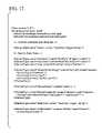
- HRESULT HrRehydratorQueryStateVariableIN OUT SERVICE_STATE_TABLE_ROW * psstr, IN LPCWSTR pcwszSTI, IN LPCWSTR pcwszControlURL, OUT LONG * plTransportStatus
- the first parameteris a SERVICE_STATE_TABLE_ROW structure that encapsulates the state variable being queried.
- the second parameteris the service type identifier and the third is the control URL of the service.
- the fourth parameterreturns the HTTP status of the operation.
- This functionwill generate an HTTP request to the control server on the device.
- the body of this requestwill be an XML fragment containing a SOAP-encoded request for the variable's value.
- the followingis an example of such a request:
- the control serverwill respond to this message with another XML fragment: the SOAP-encoded method response.
- the rehydratorwill extract the return value from this XML fragment, place it in the SERVICE_STATE_TABLE_ROW structure whose address was passed as the first parameter to the HrRehydratorQueryStateVariable( ) function and then return.
- IUPnPService::InvokeAction( )on a Service object, passing it the name of an action to invoke, and an array of arguments to the action.
- IUPnPService::InvokeAction( )calls RehydratorInvokeServiceAction( ), declared as shown below.
- HRESULT HrRehydratorInvokeServiceAction( IN SERVICE_ACTION * pAction, IN SAFEARRAY * psaInArgs, IN LPCWSTR pcwszSTI, IN LPCWSTR pcwszControlURL, IN OUT SAFEARRAY ** ppsaOutArgs, OUT VARIANT * pvReturnVal, OUT LONG * plTransportStatus)
- the first parameteris a structure describing the action to be invoked
- the secondis an array of input arguments
- the thirdis the service type identifier
- the fourthis the control URL of the service.
- the out parameters and return valueare returned in the fifth and sixth parameters, respectively.
- the HTTP status of the operationis returned in the seventh parameter.
- RehydratorInvokeServiceAction( )will send an HTTP request to the control server identified by the second parameter.
- the body of this messagewill be an XML fragment containing a SOAP-encoded method call.
- An example HTTP request to invoke an actionis shown below.
- the encoding of the body of this messageis again specified in the Service Control Protocol.
- the Rehydratorwill wait for the HTTP response to this request, which would look something like the example below.
- the RehydratorAfter receiving a response such as this, the Rehydrator will extract the return value, place it in the out parameter it was passed, and then return.
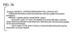
- FIGS. 31 through 43are program listings defining various interfaces used in the preferred implementation of the Rehydrator, including an IUPnPDevice Interface, an IUPnPPropertyBag Interface, an IUPnPService Interface, an IUPnPDevices Interface, and an IUPnPServices Interface.
- Control Points 104include Visual Navigation, Browser, Discovery Client, Event Subscription Client, Event Sink and Rehydrator modules.
- the Visual Navigation moduleprovides the Control Point functionality that displays the icons of discovered Devices and enables the transfer of control to a browser or application to interact with the Controlled Device.
- Visual Navigationcould be implemented as a folder of icons.
- the Discovery Clientis a module that runs in a Control Point that initiates SSDP queries.
- the Browseris the Presentation Client.
- the Rehydratoris the Control Client.
- a Control Point modulethat translates between native operating system APIs and SCPs and events.
- the Rehydratoruploads Service Descriptions from Controlled Devices and Bridges and generates appropriate SCPs in response to application API requests to invoke Actions.
- the Event Subscription Clientis a module that runs in a Control Point that sends GENA SUBSCRIBE messages to the Event Subscription Server.
- the Event Sink moduleruns in a Control Point and accepts incoming GENA event NOTIFYs.
- This serviceconsists of a TCP/HTTP server that passes the event information to interested applications running on the Control Point.
- the Event Sinkis identified by an Event Sink URL.
- This URLsupplied by a Control Point, is used as an address to send event NOTIFYs to.
- This URLis valid as an address for the lifetime of the Hostname embedded in the URL. There is no explicit relationship between Event Sink URLs and Subscription Identifiers.
- Control Points 104can retrieve a Device Description 226 by issuing an HTTP GET on a Description URL. This URL is returned in the location header of either an SSDP announcement or an SSDP query response.
- the HTTP GETmust include an accept-language header that is used to request the preferred language of the response. If the requested language is not supported, a Device Description in the default language supported by the Controlled Device or Bridge may be returned.
- An HTTP GETis used to retrieve sub elements of a Device Description that are expressed as URLs.
- URLs embedded in Device Descriptions 226take one of 3 forms: a fully qualified URL or a relative URL.
- the devicename part of the URLis a Hostname or IP address and the pathname is a filesystem path or equivalent.
- a fully qualified URLis used “as is” to establish an HTTP connection to a device.
- a relative URLdoes not contain the “:” character and is of the form:
- Relative URLSare a compact representation of the location of a resource relative to an absolute base URL. All relative URLs in a Device Description are appended to the value of the Device Description element ⁇ URLbase> to form fully qualified URLs.
- Some elements of a Device Descriptionare binary. XML does not directly support the embedding of binary data. In order to include binary data directly in a Device Description, one must convert the data to text using the Base 64 encoding scheme. This tends to increase the size of the data by 25% on the average. Much of this overhead can be eliminated if the binary data is passed by reference instead of by value.
- a URL to the datais provided in a Device Description. The binary data can be retrieved by doing a HTTP GET with that URL.
- the iconwould be retrieved with an HTTP GET of the following format:
- the HTTP responsewould look like:
- the basic layout of the Device Description 226is shown in FIG. 14 .
- the elements of the Device Descriptionare specified in the Appendix.
- FIG. 15shows an exemplary icon list in a Device Description 226 .
- the Service Description 406is a representation of the schema of a Service. It is possible to reconstruct the SST 230 , Action set 408 and SCP 402 from the Service Description.
- Service Descriptionis specified in an XML documents.
- the Service Device Description 404written in a language called Service Description Language, declares the list of state Variables and Actions associated with the Service Type to be controlled by the protocol.
- UPnP Template Language 404A Service Description, written in UPnP Template Language 404 is used to specify the list of state Variables that a SCP can query and the set of Actions that it can invoke.
- UPnP Template Languageis an XML schema, a set of rules for writing XML documents.
- FIG. 16shows an exemplary Service Description.
- This XML documentconsists of a root ⁇ Service Description> element containing two sub-elements, ⁇ serviceStateTable> and ⁇ actionList>.
- ⁇ serviceStateTable> elementWithin the ⁇ serviceStateTable> element is a ⁇ stateVariable> element for each state variable associated with the service.
- the Service in this exampleis a TV tuner with has only one state variable, currentChannel.
- the elements within the ⁇ stateVariable> elementspecify the name, data type and allowed values for the state variable. Had the Service more state variables, they would be represented by additional ⁇ stateVariable> elements within the ⁇ serviceStateTable> element.
- the ⁇ actionList> elementcontains an ⁇ action> element for every action associated with the Service.
- the elements within an ⁇ action> elementspecify the name of the action and any arguments the action may take.
- the servicesupports two actions that do not take arguments, ChannelUp and ChannelDown, and another, SetChannel, that takes a new channel number as an argument.
- the ⁇ argument> element and the elements nested within itdefine the argument.
- the ⁇ relatedStateVariable> element within ⁇ argument>specifies the name of one of the state variables to which the argument is related. In the UPnP Device Model, all arguments to actions must correspond directly to some state variable.
- FIGS. 17 and 18show an XML schema for the Service Description Language.
- the UPnP architecture 200( FIG. 3 ) requires that clients of the UPnP API be enabled to receive notifications reliably from UPnP services 210 – 217 as their states change. Since state changes are relatively common, the eventing subsystem is efficiency and performance is a major consideration in this design.
- FIG. 19 and the following discussiondescribe the Basic UPnP Eventing Architecture 600 , which encompasses both the controlled device 106 and Control Point 104 sides of the eventing service. It also includes the support APIs for both a low-level service interaction and a higher level COM-based wrapper of those APIs. The latter enables automation controllers like Visual Basic 602 to receive event notifications.
- Property change eventsare defined as any change in the value of a row of the Service State Table (SST) 230 ( FIG. 3 ) for a service 210 – 217 . This change will be reflected as a property change notification. For example, if a “VCR” device has a “VCR Transport” service, one row in that service's SST may be TapeState and the value could be TapePresent. If the tape is ejected, the new value would be TapeAbsent. This state change would be reflected as a notification sent to all subscribers.
- SSTService State Table
- a UPnP event notificationis an XML message sent over HTTP/TCP to each and every subscriber to a particular UPnP service.
- the content of the XMLis defined below.
- the important contents of this messageare the unique identifier for the subscription, the property name and new value.
- the listener to Notificationsis the SSDP service itself.
- SSDPalready listens on another multicast address for “alive” and “byebye” messages sent by UPnP devices. The same listener will listen on a TCP port for notifications sent. All subscriptions sent from that Control Point contain the same callback URL and so all notifications will be directed to that URL.
- the SSDP serviceWhen a notification arrives the SSDP service will examine the NT header of the message and determine if it is an event notification. If so, the message is parsed further to determine if it should be forwarded on to subscribers (which must exist).
- GENAdefines the format of the HTTP message, what headers can be used, and what they can be used for.
- GENAis the protocol of communication that, in a preferred embodiment, UPnP devices use to send event notifications. Therefore, UPnP devices that wish to notify Control Points of state changes are recommended to use GENA. Notification subscribers will never be required to interact with a UPnP device directly and so they are not required to use GENA.
- the eventing APIwill encapsulate this complexity. Other appropriate event transport protocols may be used, such as publish/subscribe systems.
- C Application 604Applications written in C will be able to utilize the SSDP C API 610 to receive callbacks when notifications are processed by the SSDP service. This is analogous to SSDP clients registering for notifications that services have become available.
- a Control Pointregisters for a notification, it passes as a parameter the URL of the service for which it is interested in receiving notifications. This URL is obtained from the Device Description for that service. (When a service is registered on a UPnP device, it uses this same URL to listen for subscription requests).
- the SID headeris checked against the list of subscribers it maintains. If a subscriber is found, the callback function for that subscriber is invoked, with one of the parameters being the contents of the notification message.
- the notification client that implements the callback functioncan process this message in any appropriate way.
- the UPnP API 410is a consumer of the basic C interface provided by the SSDP C API 610 component.
- the registration of notificationsis handled by the Service Object 612 inside the UPnP Object Model.
- Service objectswill register for notifications when they are created. This ensures that the SST is maintained by the UPnP API and is kept up to date. They will implement the callback function required by the registration function. If this callback function is invoked, it will pass on that notification to Control Points.
- the Control Pointscan be written in C, C++, VB, or script code, so the mechanism for passing on notifications can be different.
- a feature of the illustrated eventing systemis that it supports script languages such as VBScript 602 .
- VBScriptthis is made possible by providing a property on the Service object that, when set, contains the IDispatch pointer for a VBScript function or subroutine that will be the event handler.
- the Service object's notification callbackis invoked, it checks to see if this IDispatch pointer was set, and if so, it calls IDispatch::Invoke on DISPID 0 of that interface to call the VBScript subroutine.
- Control PointAny piece of software that searches for devices and controls them.
- Controlled DeviceA hardware or software device that announces its availability thru SSDP and allows control by Control Points.
- Notifying Resource(or simply “Resource”)—For the purposes of this document, this will always be a service contained within a UPnP Controlled Device 106 .
- Event Sourcea service that provides events.
- UPnP servicesare event sources. All notifying resources are event sources and vice versa.
- Eventmessages generated when a change in a resource's state occurs.
- Propertya single entry in the service's state table whose DefaultValue can change. Properties and events always have a one to one correspondence.
- the UPnP API 410exposes several interfaces with which a consumer can find and enumerate devices, control services, and get properties on devices and services.
- EventHandlera new property to the IUPnPService interface called EventHandler.
- RegisterNotification( ) APIis called when the Service object is created so that it can maintain a local copy of the SST for that service.
- the Service objectknows the URL of the service and therefore it can provide this as a parameter to RegisterNotification( ).
- RegisterNotification( )is also provided a callback function which is a static member of the Service object class. This function will be invoked for each and every notification sent by that particular UPnP service.
- the Service object 612includes a static member function called EventNotifyCallback( ) which is invoked for each notification sent by the UPnP service.
- the callbackis passed the entire HTTP message contents in a structure which is a parameter to the function.
- the prototypelooks like this:
- the ssdpType parametershould always be SSDP_EVENT.
- the pssdpMsg parametercontains the relevant information about the event.
- the key piece of informationis the body of the XML message.
- the bodycontains information about what property changed, what its new value is and what type it is, among other information.
- the pContext parameterwill always be the this pointer of the Service object. This allows the code to call a method to fire the event to the Control Point.
- the callbackwill parse the XML body using the XML DOM services. Property changes are iterated and the local SST is updated to reflect these changes. After this processing is done, an event notification may be fired for each property that was changed to the owner of the subscription if one exists. Depending on what environment the owner is written in (C++ or script, etc . . . ), a different mechanism for firing the event may be employed.
- a special case for this processis the very first notification received after a subscription is established. This notification contains the entire set of properties and their values and is used to locally sync up the SST. Events will not be fired to clients of the UPnP API in this case.
- EventNotifyCallback( ) functionWhen the EventNotifyCallback( ) function is called, the local copy of the SST for the service is updated. After this, an event needs to be fired if a subscriber exists. A subscriber exists if the put EventHandler( ) method was called, either from VBScript, C++ code, or another source. To abstract away this complexity, a new interface called IUPnPServiceCallback is needed.
- This interfacehas a method called StateVariableChanged( ) which takes several parameters.
- IUPnPService::AddCallback( ) functionWhen the IUPnPService::AddCallback( ) function is called, its argument is an IUnknown. This pointer is QueryInterface'd( ) for IDispatch first, and if it succeeds, then IDispatch::Invoke( ) is called with DISPID 0 to invoke the default method. This allows VBScript 602 to be called. If that fails, however, it is Queried for IUPnPServiceCallback, and if that succeeds, the StateVariableChanged( ) method is called with the same parameters as for Invoke( ). The handles C++ Control Points effectively.
- a Control PointTo subscribe to a UPnP service from C++, a Control Point instantiates a UPnP service object, and calls the IUPnPService::AddCallback( ) function. This function takes one parameter, an IUnkown interface pointer to an object that implements IUPnPServiceCallback.
- the scriptfinds the device given its UDN. When it finds the device, it queries that device for the “upnp:id”pwrdim” service. Once it finds that service, it adds an event callback to that service called “eventHandler”. This name is arbitrary.
- GENA servers 630are generally going to be UPnP Control Points.
- a GENA serveris anything that receives and processes NOTIFY messages to handle notifications from resources and sends SUBSCRIBE and UNSUBSCRIBE messages to receive notifications from resources.
- These APIsleverage the already existing SSDP APIs. The following are the changes to the APIs:
- the RegisterNotification( )allows a UPnP Control Point to request notification when an event occurs for a given UPnP service.
- the prototypeis as follows:
- Nt[in]An enumeration that determines the type of notification requested.
- the valuesare: SSDP_ALIVE—a service has become available, and SSDP_PROPCHANGE—a property has changed on the service.
- SzResourceType[in]A null-terminated string specifying the resource type desired. For SSDP_ALIVE, this is the service type, for SSDP_PROPCHANGE this is unused.
- SzEventUrl[in]A null-terminated string specifying the URL that a subscription request should be sent to.
- FnCallback[in]A pointer to a function that will be called each time a notification is received. The function pointer is defined in the SSDP spec.
- PContext[in]This parameter is included as a parameter when invoking the client-supplied callback function.
- Return ValueIf the function succeeds, the return value is a handle used in a subsequent call to the DeregisterNotification( ) function. If the function fails, the return value is INVALID_HANDLE_VALUE error code. To get extended error information, call GetLastError.
- a UPnP Control PointWhen a UPnP Control Point wishes to subscribe to notifications for a particular UPnP service, it calls the RegisterNotification( ) API. It passes to this API a notification type that identifies the type of notification being requested, a URL to which a subscription should be sent, and a callback function and context for use when the notification is received.
- RegisterNotification( )will compose a SUBSCRIBE message, using the data passed in, and send that to the URL specified by the caller.
- the Callback header of the SUBSCRIBE messagewill be composed on the fly, as an arbitrary URL for notifications to be sent to for this subscription. This callback URL will likely be a constant since the server API will always know how to handle requests sent to this URL. It will then send the SUBSCRIBE message and await a response.
- the Subscription-ID headercontains a SID which is associated with the callback function specified by the caller.
- the Control Pointshould expect an initial NOTIFY message that contains the complete set of properties maintained by the Controlled Device. This becomes the local cached SST on the Control Point side. From this point on, all modifications to the table are made via NOTIFY messages. This initial NOTIFY message will have sequence number 0 that indicates it is an initial property set and not an update. The Control Point can use this information in any way it sees fit. This ensures the Control Point's state table is always in sync with the one on the Controlled Device.
- each subscription requestincludes an arbitrary timeout value which indicates to the Controlled Device that the Control Point will be re-subscribing every n seconds indicated in the timeout header of the subscription request. If the timeout expires on the Controlled Device, the subscription is removed. The Control Point is required to re-subscribe before the timeout period has elapsed. If it fails to do so, the subscription will be terminated by the Controlled Device.
- a re-subscribe messageshould be sent.
- the re-subscribe messageis similar to the subscribe message, but it does not contain an NT or Callback header. If the Control Point is unable to re-subscribe within the timeout period, the subscription will be terminated by the Controlled Device. If the Control Point sends a re-subscribe after the Controlled Device has terminated the subscription, the Controlled Device will return “412 Precondition Failed”.
- each event notification messagewill contain a 32-bit sequence number that starts at 0 and increments for each message sent to a subscriber. If a subscriber receives a notification with a sequence number that is not exactly one more than the previous notification, it will know that it has lost events and will ignore all future notifications until it receives one with sequence number 0 again. Events with sequence number 0 indicate that the event is an “initial state” event.
- the Control Pointwill send an UNSUBSCRIBE message, followed by a SUBSCRIBE message. This is not the same as a re-subscription because re-subscriptions do not cause the Controlled Device to start the sequence over at 0. In this case, the active unsubscribe/subscribe will cause the Controlled Device to restart the sequence at 0 and send the entire state table with the first notification message.
- This example of a GENA SUBSCRIBE request and responsedemonstrates a subscription to event notifications for “service1.”
- the hostis “vcr.local.” All notifications for this service will be sent to the callback URL http://danielwe/upnp:923.
- the “Subscription-ID” headerprovides the subscriber with an identifier to use when it wants to unsubscribe to this resource.
- the “Timeout” headerindicates that the subscriber will send a re-subscription request before 10 minutes have elapsed. If the device does not receive this request within that period of time, it will remove the subscription.
- Controlled Device 106This tells the Controlled Device 106 which subscription is being renewed and restarts the timeout. When the Controlled Device receives this message, it will persist the subscriptions to disk (or other persistent data storage medium), updating the absolute timeout based on the current time and a new timeout sent by the Control Point (if it was different).
- a UPnP property change eventwill be of the following form:
- a property named “foo”has a value of “goodbye” and a property named “bar” has a value of 27.
- the XMLcontains a list of multiple properties that have changed.
- Controlled Devicebegins with the Controlled Device sending its initial state to the subscriber the first time an event is submitted by the service.
- Control Pointswill subscribe to the service first, then receive notifications for events as they occur. The first event will happen to be the initial state of the service.
- the Control Point state tablewill always be in sync with this method.
- Controlled DeviceWhen the Controlled Device sends a notification to a subscriber and receives an error. In this case, it marks the subscriber as “NeedsSync” and the next time an event is submitted, all events are sent to the subscriber.
- the problem with thisis that the API needs to keep track of which subscribers need syncing and which ones don't.
- the client of this API(the UPnP service) would need to send separate messages to each subscriber and know which ones needed all events and which ones just wanted the ones that changed.
- This methodstates that the Control Point should subscribe to event notifications, then call a function that obtained the state from the service. This means that any events that were received in the meantime would need to be matched against the incoming set of events and replaced if they were older.
- This methodleads to synchronization issues where the Control Point may receive events that are newer but when it queries for the state, it gets an older view of the table. This requires using sequence numbers to determine which information is newer. If the view of the table received by the query is too old, it has to be discarded. Alternatively, the properties that were not received by event notification would not be overwritten, but all other properties would be. Using sequence numbers make this more complicated.
- This preferred methodtakes a simpler approach. Any time the Control Point subscribes to a service, the service will immediately afterwards, send the entire contents of the state table with the first notification. This precludes the Control Point from making a query for the state table. Subsequent events update the local state table on the Control Point. If the connection is lost, the Control Point will lose its subscription. If the Control Point realizes it has not received an event after a certain amount of time has elapsed, it will re-subscribe. At that point, the Controlled Device will re-send the entire state table again, and the Control Point is ensured to be up to date.
- FIG. 21 and the following discussionare intended to provide a brief, general description of a suitable computer which may be used in the above described UPnP device control model.
- This conventional computer 820(such as personal computers, laptops, palmtops or handheld-PCs, set-tops, servers, mainframes, and other variety computers) includes a processing unit 821 , a system memory 822 , and a system bus 823 that couples various system components including the system memory to the processing unit 821 .
- the processing unitmay be any of various commercially available processors, including Intel x86, Pentium and compatible microprocessors from Intel and others, including Cyrix, AMD and Nexgen; Alpha from Digital; MIPS from MIPS Technology, NEC, IDT, Siemens, and others; and the PowerPC from IBM and Motorola. Dual microprocessors and other multi-processor architectures also can be used as the processing unit 821 .
- the system busmay be any of several types of bus structure including a memory bus or memory controller, a peripheral bus, and a local bus using any of a variety of conventional bus architectures such as PCI, VESA, AGP, Microchannel, ISA and EISA, to name a few.
- the system memoryincludes read only memory (ROM) 824 and random access memory (RAM) 825 .
- ROMread only memory
- RAMrandom access memory
- BIOSbasic input/output system
- BIOSbasic routines that help to transfer information between elements within the computer 820 , such as during start-up, is stored in ROM 824 .
- the computer 820further includes a hard disk drive 827 , a magnetic disk drive 828 , e.g., to read from or write to a removable disk 829 , and an optical disk drive 830 , e.g., for reading a CD-ROM disk 831 or to read from or write to other optical media.
- the hard disk drive 827 , magnetic disk drive 828 , and optical disk drive 830are connected to the system bus 823 by a hard disk drive interface 832 , a magnetic disk drive interface 833 , and an optical drive interface 834 , respectively.
- the drives and their associated computer-readable mediaprovide nonvolatile storage of data, data structures, computer-executable instructions, etc. for the computer 820 .
- a number of program modulesmay be stored in the drives and RAM 825 , including an operating system 835 , one or more application programs 836 , other program modules 837 , and program data 838 .
- a usermay enter commands and information into the computer 820 through a keyboard 840 and pointing device, such as a mouse 842 .
- Other input devicesmay include a microphone, joystick, game pad, satellite dish, scanner, or the like.
- These and other input devicesare often connected to the processing unit 821 through a serial port interface 846 that is coupled to the system bus, but may be connected by other interfaces, such as a parallel port, game port or a universal serial bus (USB).
- a monitor 847 or other type of display deviceis also connected to the system bus 823 via an interface, such as a video adapter 848 .
- computerstypically include other peripheral output devices (not shown), such as speakers and printers.
- the computer 820operates in a networked environment using logical connections to one or more remote computers, such as a remote computer 849 .
- the remote computer 849may be a server, a router, a peer device or other common network node, and typically includes many or all of the elements described relative to the computer 820 , although only a memory storage device 850 has been illustrated in FIG. 21 .
- the logical connections depicted in FIG. 21include a local area network (LAN) 851 and a wide area network (WAN) 852 .
- LANlocal area network
- WANwide area network
- Such networking environmentsare commonplace in offices, enterprise-wide computer networks, intranets and the Internet.
- the computer 820When used in a LAN networking environment, the computer 820 is connected to the local network 851 through a network interface or adapter 853 . When used in a WAN networking environment, the computer 820 typically includes a modem 854 or other means for establishing communications (e.g., via the LAN 851 and a gateway or proxy server 855 ) over the wide area network 852 , such as the Internet.
- the modem 854which may be internal or external, is connected to the system bus 823 via the serial port interface 846 .
- program modules depicted relative to the computer 820may be stored in the remote memory storage device. It will be appreciated that the network connections shown are exemplary and other means of establishing a communications link between the computers may be used.
- the present inventionis described below with reference to acts and symbolic representations of operations that are performed by the computer 820 , unless indicated otherwise. Such acts and operations are sometimes referred to as being computer-executed. It will be appreciated that the acts and symbolically represented operations include the manipulation by the processing unit 821 of electrical signals representing data bits which causes a resulting transformation or reduction of the electrical signal representation, and the maintenance of data bits at memory locations in the memory system (including the system memory 822 , hard drive 827 , floppy disks 829 , and CD-ROM 831 ) to thereby reconfigure or otherwise alter the computer system's operation, as well as other processing of signals.
- the memory locations where data bits are maintainedare physical locations that have particular electrical, magnetic, or optical properties corresponding to the data bits.
- FIGS. 22 and 23are intended to provide a brief, general description of a suitable embedded computing device 900 which may be used in the illustrated implementation of the invention.
- the embedded computing device 900can be any variety of device incorporating electronics to control operational functions (operational circuitry 906 ), and in which computing and networking capabilities are embedded.
- devices in which computing and networking functions can be embeddedinclude communications devices (e.g., telephones, cell phones, audio and video conferencing systems, 2-way radios, etc.), office equipment (printers, fax machines, copiers, dictation, etc.), audio-video equipment (audio and video recorders and players, including televisions, radio receivers, compact disk (CD), digital video disk (DVD), camcorders, etc.), entertainment devices (set-top boxes, game consoles, etc.), environment control equipment (thermostats, heating/ventilation/air-conditioning equipment, light switches, etc.), security systems, home appliances (coffee makers, dishwashers, clothes washer/dryer), automobiles, public facilities equipment (signs, traffic signals, etc.), manufacturing equipment, and many others.
- communications devicese.g., telephones, cell phones, audio and video conferencing systems, 2-way radios, etc.
- office equipmentprinters, fax machines, copiers, dictation, etc.
- audio-video equipmentaudio and video recorders and players, including televisions, radio
- the device 900includes a processing unit 902 , and a memory 904 to provide embedded computing capability.
- the processing unit 902has hardware interfaces to the operational circuitry 906 that operates devices functions.
- the processing unit 902can be a microprocessor or micro-controller, such as are available from Intel, Motorola, IBM, and others.
- the memory 904preferably incorporates RAM and ROM to hold software and data for basic operating code as well as for user applications.
- the device 900also includes a network adapter 908 for connecting with a network media 910 that is interconnected with the computer network in which the authoritative names registry (described below) is implemented in accordance with the invention.
- the network adapter 908can be a network interface card (or chip set integrated on a single board with the processing unit 902 ) appropriate to the particular network media 910 .
- the network mediacan be any of various wired or wireless network media, including Ethernet, IEEE 1394 (a.k.a. firewire), radio frequency (including satellite, cell, pager, commercial signal sideband, etc.), power line carrier (PLC), phone line, and television cable, among others.
- the embedded computing device 100has a software architecture 120 that conforms to the above described UPnP device control model.
- UPnPprovides a mechanism for the embedded computing device to operate in the Internet, as well as networks that have no administrator and no connection to the Internet, and hence no access to configuration services like the Dynamic Host Configuration Protocol (DHCP).
- DHCPis a mechanism for providing devices with configuration information needed to access the Internet. The mechanism functions through the use of a multicast request for configuration information that is generally responded to with an IP address and DNS server location. Additional information can only be returned in the response.
- UPnPuses the AutoIP protocol.
- AutoIPis an enhancement to DHCP that allows devices to claim IP addresses in the absence of a DHCP server or similar IP configuration authority. IP addresses are claimed from a reserved range that is not allowed to be transmitted on the open Internet; thus they are only good for the local network.
- the embedded computing device 100claims an address by randomly generating an address in the reserved range and then making an ARP request to see if anyone else has already claimed that address.
- AutoIP systemswill continually check for the presence of a DHCP server so that if one should ever come online, all the AutoIP devices will attempt to switch their IP addresses to one provided by the DHCP server. This allows a network to operate in isolation, be connected to the Internet with DHCP support and then to be returned to isolation. This type of scenario will be common in homes that use dial-up access.
- the UPnP protocolalso uses Multicast DNS for addressing the embedded computing device 900 .
- the Internet Domain Name System(DNS) is a mapping system that translates human readable domain names, like microsoft.com, into their equivalent IP address. Most corporate intranets implement an internal version of the same technology to provide the same services. In small networks, such as at home or in small business, DNS servers may not exist. Multicast DNS allows DNS requests to be multicast. This allows a machine to see requests for its own name and respond to them. Like AutoIP, Multicast DNS is only used when a DNS server is not available. (For more information, see B. Woodcock, Zocolo, and B. Manning, “Multicast Discovery of DNS Services,” IETF Internet Draft, “draft-manning-multicast-dns-01.txt.”)
- UPnPimplements a peer discovery mechanism that uses the Simple Service Discovery Protocol (SSDP) for discovery of devices on IP networks.
- SSDPis based on profiles.
- a single identifierspecifies a profile that defines a control protocol between the client and service (e.g., operational functions provided by the embedded computing device). By identifying itself with the profile, the service advertises compliance with the associated control protocol.
- UDPUser Datagram Protocol
- UPnPalso provides a Directories mechanism to allow discovery to scale—to the entire Internet if needed.
- a directoryWhen present, a directory will read all incoming service requests and respond to them itself. This requires that all services (e.g., the embedded computing device 900 ) register with the directory so that the directory is able to properly answer on their behalf.
- the directoryis also responsible for communicating with other directories in order to determine whether the service is available within the local network, the WAN and potentially the Internet.
- a proxyis a service that accepts requests and takes responsibility for finding the proper response.
- a proxyWhen a client comes online, it will perform discovery for the proxy. If the proxy is present, then the client will send all future discovery requests to the proxy. If the proxy isn't present, then the client will send all discovery requests to the reserved discovery multicast channel. Regardless of the presence of a proxy, the client's request format and procedures will always be the same. The only difference will be the address to which the client sends its requests. For services, the difference between a proxied and unproxied network is their need to answer discovery requests. On a proxied network, services need do nothing once they have registered with the proxy. On an unproxied network, they answer discovery requests directly.
- SSDPuses the UDP- and Transmission Control Protocol (TCP)-based Hyptertext Transport Protocol (HTTP) to provide for service discovery.
- SSDPuses a Uniform Resource Identifier (URI) to represent the service and the OPTIONS method to provide for discovery.
- SSDPalso will provide support for proxies. These proxies, which are really just fronts for directories, redirect discovery requests to themselves. It is the proxy's job to collect announce requests in order to determine what services are available as well as to communicate with other proxies in order to provide for scalable service discovery.
- the discovery processreturns only the basic information needed to connect to the embedded computing device. Once a service has discovered its peers, the service often needs to find out more information in order to work best with them.
- the description processreturns a schema providing descriptive data about the service.
- a schemais a structured data definition that defines a set of structured values that provide descriptive information about a service.
- UPNPuses the Extensible Markup Language (XML) for schema, because XML's self-describing structured data format provides the level of expressiveness and extensibility needed by a universal schema and data format.
- XMLExtensible Markup Language
- UPNPsupports automatic network introduction, meaning that devices and their related services have the ability to be self-describing and allow automatic configuration.
- the deviceWhen a device is plugged into the computer network, the device automatically configures itself and acquires a TCP/IP address. The device then announces its presence to other devices already on the network using a simple discovery protocol based on the Internet HTTP protocol and is immediately ready to share its services with any device that requests them.
- UPNPUPNP
- device developersare not required to develop specific device drivers to operate under UPNP.
- the task of preparing a device for operation in this network environmentthus is fairly simple.
- dynamic detectionallows an operating system to immediately begin using added devices or stop using removed devices without rebooting.
- UPNP Devicessupport automatic discovery, identification, and configuration to achieve interoperability in the home environment, but must also operate correctly in a managed corporate network. Devices can be networked instead of being attached directly to a PC, and devices are all autonomous citizens on the network, able to talk with each other and exchange information. UPNP provides a unified way of performing directory services with automatic configuration. Capability for simple discovery mechanism used in the home environment provides the ability for any device to become a node on the global Internet. Additionally, directory services can be leveraged if they are available in the corporate environment.
- UPNPprovides a common set of interfaces for accessing devices and services, enabling the operational unification of diverse media types.
- Communications protocols for Universal Plug and Playare based on industry standards, especially key Internet standards such as TCP/IP, HTML, XML, HTTP, DNS, LDAP, and others. Individual implementations for particular networks and buses are built on established protocols.
- the software architecture 920 of the embedded computing device 900includes the following software code modules that implement UPNP: device functions 922 , simple discovery 924 , Hypertext Transport Protocol (HTTP) 925 , Transmission Control Protocol/Internet Protocol (TCP/IP) stack 926 , Autonet 928 , Dynamic Host Configuration Protocol (DHCP) 930 , and physical media 910 (also shown in FIG. 22 ).
- the device functions 922is a software code module to implement the device's functionality.
- the device functions codecan include code to implement start, stop, pause, record and other functions that the VCR can perform.
- the simple discovery 924is a software code module (about 4 Kbytes) that implements a simple discovery procedure (described below) for automatic network introduction under the UPNP protocol.
- the simple discovery procedureadditionally provides an Extensible Markup Language (XML) format device description, which is downloaded to clients that access the device to allow activation of device functionality from the client.
- XMLis a textual, tag-based markup language. It was originally designed to be the “webby” simplification of SGML (Standard Generalized Markup Language), and is therefore intended to be used to create “vocabularies” of tags that can be used to apply semantic markup to documents, such as who the author was, what constitutes a paragraph (semantically, not from a display point of view), when the author last had breakfast, and so on.
- XMLis used to provide the description of services and capabilities of the embedded computing device.
- the embedded computing devicemakes its features visible to clients by providing its XML device description, which the client can use to activate device functions 922 .
- the clientcan use to activate device functions 922 .
- the client's browsercan direct the camera to zoom in/out or adjust contrast using the mechanism of XML.
- the XML device descriptioncan provide links (via a uniform resource locator or URL address) to an accompanying XSL format style sheet.
- the XSL style sheetsare used to present the data in different ways, i.e., the style sheets are applied to present different views of the same data. For example, if the device contains a file system, one style sheet can show the file selections; another shows the file sizes in some sort of diagram; yet another style sheet could make thumbnails of these image files.
- the HTTP 925is a software code modules (about 20 Kbytes) that implements the standard HTTP protocol, which is an open standard mechanism for client/server message-based communication. HTTP provides for proxying, content negotiation and security. (For more information, see R. Fielding, J. Gettys, J. Mogul, H. Frystyk, T. Berners-Lee, Hypertext Transfer Protocol—HTTP/ 1.1, IETF RFC 2068 (January 1997).)
- the TCP/IP stack 926implements the standard TCP/IP networking protocols for communication on the computer network.
- the Internet Protocol (IP)is the foundation protocol of the Internet. It defines how a single message is sent from a source through zero or more routers to its final destination.
- TCPTransmission Control Protocol
- UDPUser Datagram Protocol
- IGMPInternet Group Management Protocol
- the Autonet 928is a software code module also used for automatic network introduction via AutoIP in the UPNP protocol.
- Autonetuses a predefined set of IP addresses and, when a device is connected to the network, it pings an address in this address space. If it gets no replies, the device assumes that the address is available and assigns it to itself. To make this functionality even more useful it is combined with Multicast DNS, in which the device itself holds its own name. Thus it is not even necessary to determine what IP address the device assigned to itself, because its name can always be used instead.
- An IP Multicastis a mechanism for sending a single message to multiple recipients. IP multicasting is especially useful for discovery operations where one does not know exactly who has the information one seeks.
- Multicast DNSis a proposal to the IETF on rules for making normal DNS requests using multicast UDP. (For more information, see B. Woodcock, B. Manning, “Multicast Discovery of DNS Services”, IETF Internet Draft, “draft-manning-multicast-dns-01.txt.”)
- the DHCP 930is a software code module that implements the Dynamic Host Configuration Protocol (DHCP), which is a mechanism for providing devices with configuration information needed to access the Internet.
- DHCPDynamic Host Configuration Protocol
- the mechanismfunctions through the use of a multicast request for configuration information that is generally responded to with an IP address and DNS server location. Additional information can only be returned in the response.
- FIGS. 24 and 25show processes 934 , 940 per the UPNP protocol for automatic network introduction of the embedded computing device 900 ( FIG. 22 ) into an ad hoc (where the device does not have a configured IP address) and a configured computer network environment, respectively.
- the automatic network introduction processestablishes an appropriate configuration (e.g., with an IP address) of the embedded computing device upon connection to a server computer on a computer network, so as to enable access to the device from a client.
- the processes 934 , 940involve five phases: announce, discovery, response to discovery, autonet, and device description.
- the embedded computing device 900sends out a small multicast packet so that other devices can find it on the network.
- the multicast message packetessentially says, “I am here, I am, (say), a camera, and you can reach me at this IP address or URL.”
- the embedded computing device 900listens for a discovery packet coming from a simple discovery client, i.e., the device announces itself, then listens for discovery.
- the discovery packetalso is sent out by multicast.
- the embedded computing device 900listens to the multicast address and then parses the information from a Simple Discovery request to decide if the request is for its kind of device. If so, the device 100 then sends back a response packet containing the following information: the IP address or URL where it can be reached; identification of its own device type; and the discovery packet ID so the requesting client knows which request is being answered.
- the Autonet module 928 of the embedded computing device 900uses a predefined set of IP addresses and, when the device is connected to the network, it pings an address in this address space. If no reply is received, the device 900 assumes that the address is available and assigns it to itself. Alternatively, the device 900 may combine Autonet with Multicast DNS, and itself hold its own name. In which case, it is not necessary to determine what IP address the device assigned to itself, because its name can always be used instead.
- Both the Announce and Discovery packetsalso contain a link or a URL to an XML file that is used by the embedded computing device at the device description phase to describe itself (i.e., its functionality).
- This XML datacontains all the facts about the device.
- XMLcan also have URLs that point to appropriate style sheets (XSL files) that are used for optimal presentation.
- the XSL style sheetsare used to present the data in different ways, i.e., the style sheets are applied to present different views of the same data. For example, if the device contains a file system, one style sheet can show the file selections; another shows the file sizes in some sort of diagram; yet another style sheet could make thumbnails of these image files.
- a client that accesses and uses the embedded computing device 900 over the computer networkhas an exemplary client software architecture 950 , which includes software code modules for applications 952 , simple discovery 954 , XML 955 , LDAP 956 , TCP/IP stack 958 and a network interface card (NIC) 960 that provides a physical connection to the computer network.
- the applications 952is a software code module that provides a user interface features for locating desired devices (e.g., embedded computing device 900 ) and services on the computer network, and also user interface features to interact with the located device or service.
- the applications 952can include an Internet browser, such as the Microsoft Internet Explorer, that can present the XML device description in accordance with an associated XSL style sheet for interaction with the embedded computing device and activation of its operational functionality.
- the simple discovery 954is a module that implements the above-described simple discovery per the UPNP protocol.
- the XML 955is a module that processes the XML device description and XSL style sheets for presentation in the application's user interface.
- the LDAP 956implements the standard LDAP directory protocol for name look-up.
- the TCP/IP stack 958implements the TCP/IP protocol for communications over the computer network.
- FIG. 27illustrates a pervasive computing environment 1000 , such as may be installed in a home, office or public place, which includes a large number of embedded computing devices, such as the illustrated device 900 ( FIG. 22 ).
- the pervasive computing environment 1000includes personal computers 1002 , 1004 (e.g., of the type shown in FIG. 21 ) connected via a local area network (LAN) 1006 .
- the PC 1002is connected via a universal serial bus 1016 to a telephone modem 1010 , XDSL interface 1011 or a cable modem 1012 , which in turn provide a connection with the computer network, e.g., the Internet.
- Various embedded computing devicesalso connect to the computer network via various network connections to the PCs 1002 , 1004 .
- Theseinclude an audio device 1014 (e.g., speakers, radio tuner, microphone), and printer 1015 which connect to the PC 1004 through a USB 1017 .
- a digital camera 1020 , a handheld PC(H/PC) 1021 and another personal computing device 1022connect via an infrared port (IRDA) 1024 , which also attaches to the PC 1004 through the USB 1017 .
- IRDAinfrared port
- lighting switches 1030 and like home appliancesare connected via an A/C power line-based networking 1032 to the PC 1002 .
- a chain of IEEE 1394 cables 1048connect a digital TV 1040 , DVD player 1041 , digital video camcorder (DV/DVC) 1042 , an audio device 1043 (e.g., CD player/recorder, radio receiver, amplifier, and like audio system component), and a game console 1044 .
- Devices, such as a portable telephone 1050 and remote control 1051have a radio frequency network connection with the PC 1004 .
- the embedded computing devicesare “visible” and accessible from a client device 950 ( FIG. 27 ) also connected to the computer network.
- Universal Plug and Playis an architecture for pervasive peer-to-peer network connectivity of intelligent appliances, wireless devices, and PCs of all form factors. It is designed to bring easy-to-use, flexible, standards-based connectivity to ad-hoc or unmanaged networks whether in the home, in a small business, public spaces, or attached to the Internet. Universal Plug and Play is a distributed, open networking architecture that leverages TCP/IP and the Web technologies to enable seamless proximity networking in addition to control and data transfer among networked devices in the home, office, and public spaces. UPnP is more than just a simple extension of the plug and play peripheral model. It is designed to support zero-configuration, “invisible” networking and automatic discovery for a breadth of device categories from a wide range of vendors.
- UPnPleverages Internet components, including IP, TCP, UDP, HTTP, and XML. Like the Internet, contracts are based on wire protocols that are declarative, expressed in XML, and communicated via HTTP. IP internetworking is a strong choice for UPnP because of its proven ability to span different physical media, to enable real world multiple-vendor interoperation, and to achieve synergy with the Internet and many home and office intranets.
- UPnPhas been explicitly designed to accommodate these environments. Further, via bridging, UPnP accommodates media running non-IP protocols when cost, technology, or legacy prevents the media or devices attached to it from running IP. What is “universal” about UPnP? No device drivers; common protocols are used instead. UPnP networking is media independent. UPnP devices can be implemented using any programming language, and on any operating system. UPnP does not specify or constrain the design of an API for applications running on control points; OS vendors may create APIs that suit their customer's needs. UPnP enables vendor control over device UI and interaction using the browser as well as conventional application programmatic control.
- the UPnP Forumis an industry initiative designed to enable easy and robust connectivity among stand-alone devices and PCs from many different vendors.
- the UPnP Forumseeks to develop standards for describing device protocols and XML-based device schemas for the purpose of enabling device-to-device interoperability in a scalable networked environment.
- the UPnP Forumoversees a logo program for compliant devices.
- the UPnP Forumhas set up working committees in specific areas of domain expertise. These working committees are charged with creating proposed device standards, building sample implementations, and building appropriate test suites. This document indicates specific technical decisions that are the purview of UPnP Forum working committees.
- UPnP vendorscan build compliant devices with confidence of interoperability and benefits of shared intellectual property and the logo program. Separate from the logo program, vendors may also build devices that adhere to the UPnP Device Architecture defined herein without a formal standards procedure. If vendors build non-standard devices, they determine technical decisions that would otherwise be determined by a UPnP Forum working committee.
- the Universal Plug and Play (UPnP) Device Architecture contained hereindefines the protocols for communication between controllers, or control points, and devices. For discovery, description, control, eventing, and presentation, UPnP uses the following protocol stack. At the highest layer, messages logically contain only UPnP vendor-specific information about their devices. Moving down the stack, vendor content is supplemented by information defined by UPnP Forum working committees.
- UPnP-specific protocolsMessages from the layers above are hosted in UPnP-specific protocols, defined in this document.
- the above messagesare formatted using the Simple Service Discovery Protocol (SSDP), General Event Notification Architecture (GENA), and Simple Object Access Protocol (SOAP).
- SSDPSimple Service Discovery Protocol
- GAAGeneral Event Notification Architecture
- SOAPSimple Object Access Protocol
- the above messagesare delivered via HTTP, either a multicast or unicast variety running over UDP, or the standard HTTP running over TCP.
- IPSimple Object Access Protocol
- the remaining sections of this documentdescribe the content and format for each of these protocol layers in detail. For reference, colors in [square brackets] above indicate which protocol defines specific message components throughout this document.
- the foundation for UPnP networkingis IP addressing.
- Each devicehas a Dynamic Host Configuration Protocol (DHCP) client and search for a DHCP server when the device is first connected to the network. If a DHCP server is available, i.e., the network is managed, the device uses the IP addressed assigned to it. If no DHCP server is available, i.e., the network is unmanaged, the device uses Auto IP to get an address. In brief, Auto IP defines how a device intelligently chooses an IP address from a set of reserved addresses and is able to move easily between managed and unmanaged networks. If during the DHCP transaction, the device obtains a domain name, e.g., through a DNS server or via DNS forwarding, the device uses that name in subsequent network operations; otherwise, the device uses its IP address.
- DHCPDynamic Host Configuration Protocol
- the first step in UPnP networkingis discovery.
- the UPnP discovery protocolallows that device to advertise its services to control points on the network.
- the UPnP discovery protocolallows that control point to search for devices of interest on the network.
- the fundamental exchange in both casesis a discovery message containing a few, essential specifics about the device or one of its services, e.g., its type, identifier, and a pointer to more detailed information.
- the UPnP discovery protocolis based on the Simple Service Discovery Protocol (SSDP).
- SSDPSimple Service Discovery Protocol
- the control pointAfter a control point has discovered a device, the control point still knows very little about the device. For the control point to learn more about the device and its capabilities, or to interact with the device, the control point retrieves the device's description from the URL provided by the device in the discovery message. Devices may contain other, logical devices, as well as functional units, or services.
- the UPnP description for a deviceis expressed in XML and includes vendor-specific, manufacturer information like the model name and number, serial number, manufacturer name, URLs to vendor-specific Web sites, etc. The description also includes a list of any embedded devices or services, as well as URLs for control, eventing, and presentation.
- the descriptionincludes a list of the commands, or actions, the service responds to, and parameters, or arguments, for each action; the description for a service also includes a list of variables; these variables model the state of the service at run time, and are described in terms of their data type, range, and event characteristics.
- the section on Description belowexplains how devices are described and how those descriptions are retrieved by control points.
- the third step in UPnP networkingis control. After a control point has retrieved a description of the device, the control point can send actions to a device's service. To do this, a control point sends a suitable control message to the URL for control URL for the service (provided in the device description). Control messages are also expressed in XML using the Simple Object Access Protocol (SOAP).
- SOAPSimple Object Access Protocol
- a UPnP description for a serviceincludes a list of actions the service responds to and a list of variables that model the state of the service at run time.
- the servicepublishes updates when these variables change, and a control point may subscribe to receive this information.
- the servicepublishes updates by sending event messages. Event messages contain the names of one of more state variables and the current value of those variables.
- a special initial event messageis sent when a control point first subscribes; this event message contains the names and values for all evented variables and allows the subscriber to initialize its model of the state of the service.
- eventingis designed to keep all control points equally informed about the effects of any action. Therefore, all subscribers are sent all event messages, subscribers receive event messages for all evented variables that have changed, and event messages are sent no matter why the state variable changed (either in response to a requested action or because the state the service is modeling changed).
- the section on Eventing belowexplains subscription and the format of event messages.
- the fifth step in UPnP networkingis presentation.
- the control pointcan retrieve a page from this URL, load the page into a browser, and depending on the capabilities of the page, allow a user to control the device and/or view device status. The degree to which each of these can be accomplished depends on the specific capabilities of the presentation page and device. The section on Presentation below explains the protocol for retrieving a presentation page. 0. Addressing Addressing is Step 0 of UPnP networking. Through addressing, devices get a network address.
- Step 1where control points find interesting device(s), description (Step 2) where where control points learn about device capabilities, control (Step 3) where a control point sends commands to device(s), eventing (Step 4) where control points listen to state changes in device(s), and presentation (Step 5) where control points display a user interface for device(s).
- the foundation for UPnP networkingis IP addressing.
- Each devicehas a Dynamic Host Configuration Protocol (DHCP) client and search for a DHCP server when the device is first connected to the network. If a DHCP server is available, i.e., the network is managed, the device uses the IP addressed assigned to it.
- DHCPDynamic Host Configuration Protocol
- Auto-IPautomatic IP addressing
- a device that supports AUTO-IP and is configured for dynamic address assignmentbegins by requesting an IP address via DHCP by sending out a DHCPDISCOVER message. The amount of time this DHCP Client listens for DHCPOFFERS is implementation dependent. If a DHCPOFFER is received during this time, the device continues the process of dynamic address assignment. If no valid DHCPOFFERS are received, the device may then auto-configure an IP address.
- ARPAddress Resolution Protocol
- An ARP probeis an ARP request with the device hardware address used as the sender's hardware address and the sender's IP address set to 0s. The device will then listen for responses to the ARP probe, or other ARP probes for the same IP address. If either of these ARP packets is seen, the device considers the address in use and try a new address.
- a deviceOnce a device has a valid IP address for the network, it can be located and referenced on that network through that address. There may be situations where the end user needs to locate and identify a device. In these situations, a friendly name for the device is much easier for a human to use than an IP address. Moreover, names are much more static than IP addresses. Clients referring a device by name don't require any modification when IP address of a device changes. Mapping of the device's DNS name to its IP address could be entered into DNS database manually or dynamically according to RFC 2136. While computers and devices supporting dynamic DNS updates can register their DNS records directly in DNS, it is also possible to configure a DHCP server to register DNS records on behalf of these DHCP clients.
- a computer that needs to contact a device identified by a DNS nameneeds to discover its IP address.
- the computersubmits a DNS query according to RFC1034 and 1035 to the pre-configured DNS server(s) and receives a response from a DNS server containing the IP address of the target device.
- a computercan be statically pre-configured with the list of DNS servers. Alternatively a computer could be configured with the list of DNS server through DHCP, or after the address assignment through a DHCPINFORM message.
- Discovery Discoveryis Step 1 in UPnP networking. Discovery comes after addressing (Step 0) where devices get a network address. Through discovery, control points find interesting device(s).
- Discoveryenables description (Step 2) where control points learn about device capabilities, control (Step 3) where a control point sends commands to device(s), eventing (Step 4) where control points listen to state changes in device(s), and presentation (Step 5) where control points display a user interface for device(s).
- Discoveryis the first step in UPnP networking. When a device is added to the network, the UPnP discovery protocol allows that device to advertise its services to control points on the network. Similarly, when a control point is added to the network, the UPnP discovery protocol allows that control point to search for devices of interest on the network.
- the fundamental exchange in both casesis a discovery message containing a few, essential specifics about the device or one of its services, e.g., its type, identifier, and a pointer to more detailed information.
- a new deviceWhen a new device is added to the network, it multicasts a number of discovery messages advertising its embedded devices and services. Any interested control point can listen to the standard multicast address for notifications that new capabilities are available. Similarly, when a new control point is added to the network, it multicasts a discovery message searching for interesting devices, services, or both. All devices listen to the standard multicast address for these messages and responds if any of their embedded devices or services match the search criteria in the discovery message.
- a control pointmay learn of a device of interest because that device sent discovery messages advertising itself or because the device responded to a discovery message searching for devices. In either case, if a control point is interested in a device and wants to learn more about it, the control point uses the information in the discovery message to send a description query message.
- the section on Descriptionexplains description messages in detail.
- a deviceWhen a device is removed from the network, it multicasts a number of discovery messages revoking it's earlier announcements, effectively declaring that it's embedded devices and services will not be available.
- the time-to-live (TTL) of each IP packet for each multicast messagedefaults to 4 and is configurable.
- the UPnP Device Architecture(defined herein) is versioned with both a major and a minor version, usually written as major.minor, where both major and minor are integers. Advances in minor versions is a compatible superset of earlier minor versions of the same major version. Advances in major version are not required to be supersets of earlier versions and are not guaranteed to be backward compatible. Version information is communicated in discovery and description messages. In the former, each discovery message includes the version of UPnP networking that the device supports. As a backup, the latter also includes the same information. This section explains the format of version information in discovery messages and specific requirements on discovery messages to maintain compatibility with advances in minor versions.
- the UPnP discovery protocolallows that device to advertise its services to control points. It does this by multicasting discovery messages to a standard address and port. Control points listen to this port to detect when new capabilities are available on the network.
- a devicemulticasts a number of discovery messages corresponding to each of its embedded devices and services. Each message contains information specific to the embedded device (or service) as well as information about its enclosing device. Messages include duration until the advertisements expire; if the device remains available, the advertisements are re-sent with (with new duration). If the device becomes unavailable, the device explicitly cancels its advertisements, but if the device is unable to do this, the advertisements will expire on their own.
- devicesTo send (and receive) advertisements, devices (and control points) use the following subset of the overall UPnP protocol stack. (The overall UPnP protocol stack is listed at the beginning of this document.)
- discovery messagescontain vendor-specific information, e.g., URL for the device description and device identifier.
- vendor contentis supplemented by information from a UPnP Forum working committee, e.g., device type.
- UPnP-specific protocolsdefined in this document.
- the above messagesare delivered via a multicast variant of HTTP that has been extended using General Event Notification Architecture (GENA) methods and headers and Simple Service Discovery Protocol (SSDP) headers.
- GAAGeneral Event Notification Architecture
- SSDPSimple Service Discovery Protocol
- the HTTP messagesare delivered via UDP over IP.
- colors in [square brackets] aboveindicate which protocol defines specific headers and values in discovery messages listed below.
- AdvertisementDevice Available—NOTIFY with ssdp:alive
- ssdpalive
- a deviceWhen a device is added to the network, it multicasts discovery messages to advertise its root device, to advertise any embedded devices, and to advertise its services.
- Each discovery messagecontains four major components:
- NT USN Three discovery messages for the root device1 device UUID device UUID 2 device type device UUID and :: and device type 3 upnp:rootdevice device UUID and :: and upnp:rootdevice Two discovery messages for each embedded device. 1 device UUID device UUID 2 device type device UUID and :: and device type Once for each service. 1 service type device UUID and :: and service type If a root device has d embedded devices and s embedded services but only k distinct service types, this works out to 3+2d+k requests. This advertises the full extend of the device's capabilities to interested control points. These messages are sent out as a series with roughly comparable expiration times; order is unimportant, but refreshing or canceling individual messages is prohibited.
- Choosing an appropriate duration for advertisementsis a balance between minimizing network traffic and maximizing freshness of device status. Relatively short durations close to the minimum of 1800 seconds will ensure that control points have current device status at the expense of additional network traffic; longer durations, say on the order of a day, compromise freshness of device status but can significantly reduce network traffic.
- device vendorschoose a value that corresponds to expected device usage: short durations for devices that are expected to be part of the network for short periods of time, and significantly longer durations for devices expected to be long-term members of the network. Due to the unreliable nature of UDP, devices send each of the above discovery messages more than once.
- the devicere-sends its advertisements periodically (cf. CACHE-CONTROL below).
- UDP packetsare also bounded in length (perhaps as small as 512 Bytes in some implementations) and that there is no guarantee that the above 3+2d+k messages will arrive in a particular order.
- a deviceWhen a device is added to the network, it sends a multicast request with method NOTIFY and ssdp:alive in the NTS header in the following format. Values in italics are placeholders for actual values.
- Requestapplies generally and not to a specific resource.
- discovery messagesinclude an expiration value in a CACHE-CONTROL header (as explained above); if not re-advertised, the discovery message eventually expires on its own and is removed from any control point cache.
- Requestapplies generally and not to a specific resource.
- Multicast channel and port reserved for SSDPIs 239.255.255.250:1900.
- search messagescontain vendor-specific information, e.g., the control point, device, and service identifiers. Moving down the stack, vendor content is supplemented by information from a UPnP Forum working committee, e.g., device or service types. Messages from the layers above are hosted in UPnP-specific protocols, defined in this document. In turn, search requests are delivered via a multicast variant of HTTP that has been extended using Simple Service Discovery Protocol (SSDP) methods headers.
- SSDPSimple Service Discovery Protocol
- Search responsesare delivered via a unicast variant of HTTP that has also been extended with SSDP. (GENA is not involved when control points search for devices.) Both kinds of HTTP messages are delivered via UDP over IP. For reference, colors in [square brackets] above indicate which protocol defines specific headers and values in discovery messages listed below. 1.2.2 Discovery: Search: Request with M-SEARCH When a control point is added to the network, it sends a multicast request with method M-SEARCH in the following format. Values in italics are placeholders for actual values.
- Requestapplies generally and not to a specific resource.
- Multicast channel and port reserved for SSDPIs 239.255.255.250:1900.
- Search Target.Is one of the following. (cf. NT header in advertisement.) Single URI.
- a devicesends a response in the following format. (Compare to multicast request with method NOTIFY and ssdp:alive in the NTS header above.) Values in italics are placeholders for actual values.
- Step 2 in UPnP networkingDescription comes after discovery (Step 1) where control points find interesting device(s). And description enables control (Step 3) where a control points send commands to device(s), eventing (Step 4) where control points listen to state changes in device(s), and presentation (Step 5) where control points display a user interface for device(s). After a control point has discovered a device, the control point still knows very little about the device—only the information that was in the discovery message, i.e., the device's (or service's) UPnP type, the device's universally-unique identifier, and a URL to the device's UPnP description.
- the control pointretrieves the device's description from the URL provided by the device in the discovery message.
- the UPnP description for a deviceincludes vendor-specific, manufacturer information like the model name and number, serial number, manufacturer name, URLs to vendor-specific Web sites, etc. (details below).
- the descriptionalso includes a list of any embedded devices or services, as well as URLs for control, eventing, and presentation. This section explains embedded devices; the section on Control explains how services are described, and the sections on Control, Eventing, and Presentation explain how URLs for control, eventing, and presentation are used, respectively. Note that a single physical device may include multiple logical devices.
- Multiple logical devicescan be modeled as a single root device with embedded devices (and services) or as multiple root devices (perhaps with no embedded devices). In either case, there is one UPnP description for each root device, with embedded device descriptions as needed.
- the UPnP description for a deviceis written by a UPnP vendor. The description is in XML syntax and is usually based on a standard UPnP Device Template.
- a UPnP Device Templateis produced by a UPnP Forum working committee; they derive the template from the UPnP Template Language, which was derived from standard constructions in XML. This section explains the format for a UPnP device description, UPnP Device Templates, and the part of the UPnP Template Language that covers devices.
- UPnP Template Language(The section on Control explains the part of the UPnP Template Language that covers services.) Retrieving the UPnP description for a device is simple: the control point issues an HTTP GET request on the URL in the discovery message, and the device returns the description document. The protocol stack, method, headers, and body for the response and request are explained in detail below. UPnP vendors can differentiate their devices by extending services, including additional UPnP services, or embedding additional UPnP devices. When a control point retrieves a particular device's description, these added features are exposed to the control point for control, eventing, and presentation.
- Model nameSpecified by UPnP vendor. String. Is ⁇ 32 characters.
- Model numberSpecified by UPnP vendor. String. Is ⁇ 32 characters.
- Serial numberSpecified by UPnP vendor. String. Is ⁇ 64 characters.
- HOSThost for device description:port for device description
- Unicode string(Same as string data type defined by XML.)
- control pointmay retrieve a service description using a description URL in the description (vs. discovery) message.
- description URLin the description (vs. discovery) message.
- control pointsuse the following subset of the overall UPnP protocol stack. (The overall UPnP protocol stack is listed at the beginning of this document.)
- control and query messagescontain vendor-specific information, e.g., URL for control and argument values.
- vendor contentis supplemented by information from a UPnP Forum working committee, e.g., service types, action names, argument names.
- UPnP-specific protocolsdefined in this document.
- the above messagesare formatted using a Simple Object Access Protocol (SOAP) header and body elements, and the messages are delivered via HTTP over TCP over IP.
- SOAPSimple Object Access Protocol
- colors in [square brackets] aboveindicate which protocol defines specific header elements in the subscription messages listed below.
- SOAPdefines additional HTTP headers, and to ensure that these are not confused with other HTTP extensions, SOAP follows the HTTP Extension Framework and specifies a SOAP-unique URI in the MAN header and prefixes the HTTP method with M-. In this case, the method is M-POST. Using M-POST requires the HTTP server to find and understand the SOAP-unique URI and SOAP-specific headers. To provide firewalls and proxies greater administrative flexibility, SOAP specifies that requests first be attempted without the MAN header or M-prefix. If the request is rejected with a response of “405 Method Not Allowed”, then a second request is sent using the MAN header and M-prefix.
- a control message sent using the POST methodwithout the MAN header
- an explanation of the headers and bodyThis is immediately followed by a listing of a control message sent using the M-POST method and MAN header.
- a control messagemay include an key to indicate whether the control point has received the most recent message.
- the body of a control messageincludes two SOAP headers, one for the event subscription UUID, and one for the key itself. Both are illustrated in the listings below. The section on Eventing explains the contents of the two headers in detail.
- a control pointsends a request with method POST in the following format. Values in italics are placeholders for actual values.
- Headers for a response when a service does not accept an action requestare the same as headers for a response when a service does. See above.
- Invalid action namei.e., no action by that name at this service.
- control pointsmay also poll the service for the value of a state variable by sending a query message.
- a query messagemay query only one state variable; multiple query messages is sent to query multiple state variables.
- headers and body elementsappearing in the listing above. All header values and element names are case sensitive; values are not case sensitive except where noted. Except where noted, the order of elements is insignificant. Headers ACCEPT-LANGUAGE
- headers for a response when a service cannot provide a valueare the same as headers for a response when a service does. See above.
- Invalid variable namei.e., no state variable by that name at this service.
- Eventing Eventingis Step 4 in UPnP networking. Eventing comes after discovery (Step 1) where control points find interesting device(s), and after description (Step 2) where control points learn about device capabilities. Eventing is intimately linked with control (Step 3) where control points send actions to devices. Through even tin g, control points listen to state changes in device(s). Control and eventing are complementary to presentation (Step 5) where control points display a user interface provided by device(s). After a control point has (1) discovered a device and (2) retrieved a description of the device, the control point has the bare essentials for eventing.
- a UPnP description for a serviceincludes a list of actions the service responds to and a list of variables that model the state of the service at run time. If one or more of these state variables are evented, then the service publishes updates when these variables change, and a control point may subscribe to receive this information.
- a control pointsends a subscription message. If the subscription is accepted, the service responds with a duration for the subscription. To keep the subscription active, a control point renews its subscription before the subscription expires.
- Event messagescontain the names of one of more state variables and the current value of those variables, expressed in XML.
- a special initial event messageis sent when a control point first subscribes; this event message contains the names and values for all evented variables and allows the subscriber to initialize its model of the state of the service.
- eventingis designed to keep all control points equally informed about the effects of any action.
- Some state variablesmay change value too rapidly for eventing to be useful.
- One alternativeis to filter, or moderate, the number of event messages sent due to changes in a variable's value.
- Some state variablesmay contain values too large for eventing to be useful; for this, or other reasons, a service may designate one or more state variables as non evented and never send event messages to a subscriber. To determine the current value for such non-evented variables, control points poll the service explicitly.
- control messagesmay include a key. With each new event message a service generates, the service increments the key, and includes that key in the event message. When a control point sends a control message, it may choose to include a key. If a control message includes a key, the service checks to see if the key is current, i.e., if no events have been sent since this key was issued. If the key is current (or if there was no key in the control message), then the service acknowledges the action request.
- control points and servicesuse the following subset of the overall UPnP protocol stack. (The overall UPnP protocol stack is listed at the beginning of this document.) At the highest layer, subscription and event messages contain vendor-specific information like URLs for subscription and duration of subscriptions or specific variable values. Moving down the stack, vendor content is supplemented by information from a UPnP Forum working committee, like service identifiers or variable names. Messages from the layers above are hosted in UPnP-specific protocols, defined in this document.
- Request line SUBSCRIBE Method defined by GENApublisher path Path component of eventing URL (eventSubURL sub element in service element in device description). Single, relative URL. HTTP/1.1 HTTP version. Headers HOST Domain name or IP address and optional port components of eventing URL (eventSubURL sub element in service element in device description). If the port is missing or empty, port 80 is assumed.
- CALLBACK Locationto send event messages to. Defined by UPnP vendor. If there is more than 1 URL, when the service sends events, it will try these URLs in order until one succeeds. One or more URLs separated by angle brackets. NT Notification Type. Is upnp:event. SID (No SID header is used to subscribe.) TIMEOUT
- Request line SUBSCRIBE Method defined by GENApublisher path Path component of eventing URL (eventSubURL sub element in service element in device description). Single, relative URL. HTTP/1.1 HTTP version. Headers HOST Domain name or IP address and optional port components of eventing URL (eventSubURL sub element in service element in device description). If the port is missing or empty, port 80 is assumed.
- CALLBACKNo CALLBACK header is used to renew an event subscription.
- NTNo NT header is used to renew an event subscription.
- a servicesends a response in the following format.
- Values in italicsare placeholders for actual values.
- the servicesends a response with one of the following errors.
- control pointresponds with one of the following errors.
Landscapes
- Engineering & Computer Science (AREA)
- Computer Networks & Wireless Communication (AREA)
- Signal Processing (AREA)
- Automation & Control Theory (AREA)
- Computing Systems (AREA)
- Health & Medical Sciences (AREA)
- Computer Security & Cryptography (AREA)
- General Health & Medical Sciences (AREA)
- Medical Informatics (AREA)
- Computer And Data Communications (AREA)
- Telephonic Communication Services (AREA)
- Selective Calling Equipment (AREA)
- Communication Control (AREA)
- Telephone Function (AREA)
- Information Transfer Between Computers (AREA)
Abstract
Description
| Control Point | Controlled Device |
| Function | Module | Function | Module |
| Initiate discovery of | Discovery Client | Respond to | Discovery |
| Controlled Devices. | discovery | Server | |
| requests. | |||
| Retrieve Device | Description Client | Provide Device | Description |
| Descriptions. | Descriptions. | Server | |
| Display a folder of | Visual Navigation | ||
| icons per discovered | |||
| Device and allow | |||
| transfer of control to | |||
| a selected device. | |||
| View user interface | Web Browser | Provide user | Presentation |
| exposed by a | inteface for | (Web) | |
| Controlled Device. | remote Control | Server | |
| Points. | |||
| Execute | Application | ||
| applications. | Execution | ||
| Environment | |||
| Invoke Actions on a | Rehydrator | Accept incom- | Control Ser- |
| Controlled Device | ing Actions in | ver plus na- | |
| by sending Service | SCPs and | tive control | |
| Control Protocols in | execute them. | logic | |
| response to local | |||
| API calls. | |||
| Inform a Controlled | Event Subscription | Accept requests | Event Sub- |
| Device of a desire to | Client | for Events and | scription |
| receive Events. | remember | Server | |
| them. | |||
| Receive an Event. | Event Sink | Send an Event. | Event Source |
- A Service State Table (SST)230, which represents the current state of the Service. The Service State Table is a logical table consisting of rows of [Variable, Type, Legal Values, Default Value, Current Value] that represents the current electrical, mechanical and/or logical state of a Service. SST instances are stored on the Controlled Device itself and are the ultimate authority of the state of the Service. All local user interface, such as front panels or wireless remotes are required to update the SST on UPnP compliant devices.
- The
SST 230 can be used to represent the operational mode of device or to act as an information source or sink for structured data or simple files. The SST of a VCR254 (FIG. 4 ) could represent the current transport mode, tuner channel selection, input and output switch selections, audio and video decoding format and current timer program. The SST of clock251 (FIG. 4 ) would likely represent the current time. The SST of an image rendering device could implement a video frame-buffer that can accept raw pixel information or formatted JPG files. The SST of an audio or video playback device could implement a transfer buffer or queue of material to be played. The SST of PDA could implement a collection of formatted data that has changed and needed to be synchronized with another device, in addition to a transfer buffer for accepting incoming formatted data. - The logical structure of a SST published in the Service Description, but the actual storage format of an instance of a SST is entirely up the device. The only interaction with a SST is through a formal application level network protocol.
- A
Control Server 232, which accepts incoming Actions. The Actions are declared in the Service's Service Description. This module runs in a Controlled Device or Bridge and responds to Actions invoked on a Service by a Control Point. Actions are encoded using the Service Control Protocol (SCP) specified in the Service Description. This service consists of a TCP/HTTP server than passes control to the native control logic of a Service, updates the SST and generates an event if the SST changes. The Control Server passes the Action to the Service's native Action processing logic and waits for Action completion. When the Action is completed successfully, the SST is updated, an event is generated, if necessary, and a successful response is returned to the Control Point. In case of an illegal Action or unsuccessful Action, no changes are made to the SST and a failure response is returned. The Action and response sequence is payload to a TCP/HTTP request/response. - An Event Subscription Server and
Event Source 234. The Event Subscription Server is a module that runs in a Controlled Device or Bridge that responds to GENA SUBSCRIBE requests from Control Points. A SUBSCRIBE informs the Controlled Device or Bridge of the Control Point's desire to receive future events. This service consists of a TCP/HTTP server that adds the Control Point's Event Sink URL to the list of destinations to be NOTIFY'd whenever the Service State Table (SST) associated with the Service changes. The Event Subscription Server accepts incoming GENA SUBSCRIBE messages from Control Points and adds them to a list of Control Points interested in SST change events from the Service. - The Event Source is a module that runs in a Controlled Device or Bridge that sends GENA NOTIFYs to the Event Sink Servers of SUBSCRIBES Control Points. The Event Source initiates a TCP/HTTP connection to each interested Control Point and sends a GENA NOTIFY each time the Service's SST changes. The NOTIFY payload includes the changed contents of the SST.
- A Control URL that identifies the Control Server. This URL can be used by a Control Point to navigate to the Control Server of a Controlled Device or Bridge. This URL is returned in the Device Description and is valid as an address for the lifetime of the Hostname embedded in the URL. All Services have an associated Control URL.
- An Event URL that identifies the Event Subscription Server. The Event URL can be used by a Control Point to navigate to the Event Subscription Server of a Controlled Device or Bridge. This URL is returned in the Device Description and is valid as an address for the lifetime of the Hostname embedded in the URL. Only services that have evented state variables have an associated Event Subscription URL.
- The definition of the SST. SST layouts are logically specified in terms of rows of [Variable, Type, Legal Values, Default Value]. The actual instance of a SST would also include a Current Value field in every row.
- The definition of the Service Action set that can be invoked against the Service's SST. Actions are logically specified in terms of Action (Variable=New Value, Variable=New Value, . . . ). If an Action results in more than a single Variable change, the updates are atomic and the Action will fail if it is illegal to make the specified change to any one Variable.
- The definition of a structured unit of data called a Service Description. Service Description is used to advertise the layout (schema) of the SST and Action set of the Service to a Control Point or Bridge. The Service Description enables the Control Point to invoke Actions (through the Rehydrator) on the Controlled Device without any prior or persistent knowledge of the capabilities of the device. The Service Description is uploaded from the Controlling Device as part of the Device Description. An automated tool that accepts the SST definition and Action set definition as inputs can generate the Service Description for a Service.
- The Service Description is a formal representation of the schema of a Service. The Service Description declares the rows of a Service's SST and the associated Action set. Service Descriptions are uploaded from Controlling Devices in their Device Descriptions and enable Control Points or Bridges to invoke Actions on the Service without any prior or persistent knowledge of the capabilities (or schema) of the Service. There is exactly one Service Description per Service Definition. Service Descriptions adhere to XML grammar.
- The definition of a network protocol used to invoke Actions against the SST associated with a Service and to return results. An automated tool that accepts the SST definition and Action set definition as inputs can generate a Service Control Protocol (SCP) for a Service. The SCP can also be generated from the Service Description. The Rehydrator's job is to convert Service Descriptions into messages that conform to the SCP. The reason for a formal SCP specification is to enable the implementation of the Control Server itself and to enable simple peer-to-peer device interoperation using only published protocols.
- The Service Control Protocol (SCP) is the protocol used to invoke Actions of a Service and to return results. There is exactly one SCP per Service Definition. SCPs adhere to the grammar of SCP XML schema. SCPs can be generated by an automated tool that accepts a SST Definition and an Action Set Definition as input.
- An identifier, called the Service Type Identifier, that identifies a unique Service Definition. The Service Type is a classification of Services by their function. Service Definitions are versioned in controlled manner. Every later version of a Service must be proper superset of the previous version. This identifier adheres to the format of a Uniform Resource Identifier (URI). See, T. Berners-Lee, R. Fielding, L. Masinter,Uniform Resource Identifiers(URI):Generic Syntax, IETF RFC 2396 (August 1998).
- One or more Device Types.
- One or more Services.
- Optionally, one or more Devices.
- Optionally, a Presentation (web)
Server 220–223 that can be used to expose Device user interface. The Presentation Server is a module that runs in a Controlled Device that responds to HTTP GETs or Presentation URLs and returns user interface using web technologies (JavaScript, Jscript®, ECMAScript, VBScript, ActiveX®, Java Applet, etc.). Every Presentation Server has an associated Presentation URL that can be used by a Control Point to navigate to the Presentation Server of a Controlled Device. This URL is returned in the Device Description and is valid as an address for the lifetime of the Hostname embedded in the URL. All Devices, including non-Root Devices, can have an associated Presentation URL. - A globally unique identifier called the Unique Device Name (UDN). The UDN is the fundamental identifier of an instance of a Device. The UDN is globally unique and permanent, even across power cycles and physical location changes. The UDN is the only UPnP device identifier guaranteed never to change. UPnP enables searches for devices by UDN. Every Device, including Root Devices, has exactly one UDN.
- A Device Friendly Name. The Device Friendly Name is a human readable string that is initialized by vendors at the time of manufacture of a Device. Every Device, including Root Devices, has a Device Friendly Name. A typical Device Friendly Name will contain manufacturer and model information, and is used to enable a more precise identification of a UPnP Device from the set of discovered Devices. Once identified, the Unique Device Name (UDN) can be used to unambiguously identify the same Device in the future. UPnP enables Device Friendly Names to be changed by Control Points. The Device Friendly Name should not be used as device identifier.
- The fixed elements of the Device Description that describe the Device.
- The required hierarchy of Devices and Service Definitions.
- A Device Type Identifier. The Device Type Identifier is a unique identifier that identifies a Device Definition. This identifier adheres to the format of a Uniform Resource Identifier (URI). See, T. Berners-Lee, R. Fielding, L. Masinter,Uniform Resource Identifiers(URI):Generic Syntax, IETF RFC 2396 (August 1998).
- The required hierarchy of Devices and Service Definitions of minimum versions.
| UPnP Addresses |
| URL | Function |
| Description | Points to the Description Server and Document path on a |
| URL | Root Device. This URL is returned by the Description |
| Server as part of the discovery process. | |
| Presentation | Points to a Presentation (web) Server on a Controlled |
| URL | Device. Every device, root or nested, may have a |
| Presentation URL. This URL can be entered into the | |
| address bar of a web browser to navigate to the root web | |
| page of a Device. This URL is returned in the Device | |
| Description. | |
| Control URL | Points to the Control Server implementing a Service on a |
| Controlled Device. There is one Control URL per instance | |
| of a Service. This URL is returned in the Device | |
| Description. | |
| Event Sub- | Points to an Event Subscription Server on a Controlled |
| scription | Device. This URL is returned in the Device Description. |
| URL | |
| Event Sink | Points to an Event Sink (an HTTP Server) on a Control |
| URL | Point. This URL is specified by the Control Point in the |
| GENA SUBSCRIBE message. | |
| UPnP SSDP Level Searches and Results |
| Search for | Returns |
| A unique Root | A single Description URL pointing to the Description |
| Device (by UDN) | Server and Document path on the Root Device. |
| A unique non- | A single Description URL pointing to the Description |
| Root Device (by | Server and Document path on the Root Device that |
| UDN) | contains the non-Root Device. |
| Type of Device | A set of Description URLs pointing to the Description |
| Servers/Document paths of all Root Devices that | |
| match the Device Type, or contain a non-Root Device | |
| that matches the Device Type. | |
| Type of Service | A set of Description URLs pointing to the Description |
| Servers/Document paths of all Root Devices that | |
| contain a matching Service, or contain a non-Root | |
| Device that contains a matching Service. | |
| upnp:searchtype: [ allformat | UDNformat | srvformat | ||
| | devformat ] | ||
| search type = [ UDN | SrvType | DevType | all ] | ||
| allformat = all | ||
| UDNformat = UDN:namespace:uniqueid | ||
| namespace = [ GUID | IEEEMAC | 1394] | ||
| srvformat = SrvType:servicetype:version | ||
| devformat = DevType:devicetype | ||
| UPnP SSDP Announcements |
| UPnP Notification | ||
| Announcement | Type | SSDP USN |
| “all” | Root Device UDN | |
| Unique Root Device | Root Device UDN | Root Device UDN |
| Unique non-Root | Non-Root Device | Non-Root Device UDN |
| Device | UDN | |
| Device Type | Device Type | Root Device UDN + Device |
| Identifier | Type Identifier | |
| Service Type | Service Type | Root Device UDN + Service |
| Identifier | Type Identifier | |
| HRESULT |
| HrRehydratorCreateServiceObject ( |
| IN | LPCWSTR | pcwszSTI, |
| IN | LPCWSTR | pcwszControlURL, |
| IN | LPCWSTR | pcwszEventSubURL, |
| IN | LPCWSTR | pcwszId, |
| IN | IXMLDOMDocument | * pSCPD, |
| OUT | IUPnPService | ** pNewServiceObject) |
| HRESULT |
| HrRehydratorQueryStateVariable( |
| IN | OUT SERVICE_STATE_TABLE_ROW * psstr, |
| IN | LPCWSTR | pcwszSTI, |
| IN | LPCWSTR | pcwszControlURL, |
| OUT | LONG | * plTransportStatus) |
| POST path of control URL HTTP/1.1 |
| HOST: host of control URL:port of control URL |
| CONTENT-LENGTH: bytes in body |
| CONTENT-TYPE: text/xml; charset=“utf-8” |
| SOAPACTION: “urn:schemas-upnp-org:control-1-0#QueryStateVariable” |
| <s:Envelope |
| xmlns:s=“http://schemas.xmlsoap.org/soap/envelope/” |
| s:encodingStyle=“http://schemas.xmlsoap.org/soap/encoding/”> |
| <s:Body> |
| <u:QueryStateVariable xmlns:u=“urn:schemas-upnp-org:control-1-0”> |
| <u:varName>variableName</u:varName> |
| </u:QueryStateVariable> |
| </s:Body> |
| </s:Envelope> |
| HTTP/1.1 200 OK |
| CONTENT-LENGTH: bytes in body |
| CONTENT-TYPE: text/xml; charset=“utf-8” |
| DATE: when response was generated |
| EXT: |
| SERVER: OS/version UPnP/1.0 product/version |
| <s:Envelope |
| xmlns:s=“http://schemas.xmlsoap.org/soap/envelope/” |
| s:encodingStyle=“http://schemas.xmlsoap.org/soap/encoding/”> |
| <s:Body> |
| <u:QueryStateVariableResponse xmlns:u=“urn:schemas-upnp-org:control- |
| 1-0”> |
| <return>variable value</return> |
| </u:QueryStateVariableResponse> |
| </s:Body> |
| </s:Envelope> |
| HRESULT |
| HrRehydratorInvokeServiceAction( |
| IN | SERVICE_ACTION | * pAction, |
| IN | SAFEARRAY | * psaInArgs, |
| IN | LPCWSTR | pcwszSTI, |
| IN | LPCWSTR | pcwszControlURL, |
| IN | OUT SAFEARRAY | ** ppsaOutArgs, |
| OUT | VARIANT | * pvReturnVal, |
| OUT | LONG | * plTransportStatus) |
| POST path of control URL HTTP/1.1 |
| HOST: host of control URL:port of control URL |
| CONTENT-LENGTH: bytes in body |
| CONTENT-TYPE: text/xml; charset=“utf-8” |
| SOAPACTION: “urn:schemas-upnp-org:service:serviceType:v#action- |
| Name” |
| <s:Envelope |
| xmlns:s=“http://schemas.xmlsoap.org/soap/envelope/” |
| s:encodingStyle=“http://schemas.xmlsoap.org/soap/encoding/”> |
| <s:Body> |
| <u:actionName xmlns:u=“urn:schemas-upnp-org:service:serviceType:v”> |
| <argumentName>in arg value</argumentName> |
| other in args and their values go here, if any |
| </u:actionName> |
| </s:Body> |
| </s:Envelope> |
| HTTP/1.1 200 OK | ||
| CONTENT-LENGTH: bytes in body | ||
| CONTENT-TYPE: text/xml; charset=“utf-8” | ||
| DATE: when response was generated | ||
| EXT: | ||
| SERVER: OS/version UPnP/1.0 product/version | ||
| <s:Envelope | ||
| xmlns:s=“http://schemas.xmlsoap.org/soap/envelope/” | ||
| s:encodingStyle=“http://schemas.xmlsoap.org/soap/encoding/”> | ||
| <s:Body> | ||
| <u:actionNameResponse xmlns:u=“urn:schemas-upnp- | ||
| org:service:serviceType:v”> | ||
| <argumentName>out arg value</argumentName> | ||
| other out args and their values go here, if any | ||
| </u:actionNameResponse> | ||
| </s:Body> | ||
| <s:Envelope> | ||
| <iconList> | ||
| <icon> | ||
| <size>16</size> | ||
| <imageType>PNG</imageType> | ||
| <color>1</color> | ||
| <depth>8</depth> | ||
| <image> | ||
| “http://device.local/iconpath/icon.png”/> | ||
| </icon> | ||
| </iconList> | ||
| static VOID | ||
| CUPnPService::EventNotifyCallback(SSDP_CALLBACK_TYPE | ||
| ssdpType, | ||
| SSDP_MESSAGE *pssdpMsg, | ||
| LPVOID pcontext); | ||
| Dim devicefinder | ||
| Set devicefinder = | ||
| CreateObject(“UPnP.UPnPDeviceFinder.1”) | ||
| Dim device | ||
| Set device = devicefinder.FindByUDN(“uuid:929f28c3- | ||
| 3ada-4c97-8238-f62e08124889”) | ||
| Dim args(0) | ||
| Dim File(1) | ||
| Dim Vol(1) | ||
| set svc = device.services(“upnp:id:pwrdim”) | ||
| svc.AddCallback GetRef(“eventHandler”) | ||
| Sub eventHandler(callbackType, svcObj, varName, | ||
| value) | ||
| If (callbackType = “VARIABLE_UPDATE”) Then | ||
| select case svcObj.Id | ||
| case “upnp:id:pwrdim” | ||
| select case varName | ||
| Case “Power” Power.innerText = value | ||
| Case “Level” Level.innerText = value | ||
| end select | ||
| end select | ||
| End If | ||
| End Sub | ||
| HANDLE WINAPI RegisterNotification | ||
| (NOTIFY_TYPE nt, CHAR * szType, | ||
| CHAR *szEventUrl, | ||
| SERVICE_CALLBACK_FUNC fnCallback, | ||
| VOID *pContext) | ||
| ServiceCallbackFunc | ||
| typedef enum_SSDP_CALLBACK_TYPE { | ||
| SSDP_FOUND = 0, | ||
| SSDP_ALIVE = 1, | ||
| SSDP_BYEBYE = 2, | ||
| SSDP_DONE = 3, | ||
| SSDP_EVENT = 4, | ||
| SSDP_DEAD = 5, | ||
| } SSDP_CALLBACK_TYPE, *PSSDP_CALLBACK_TYPE; | ||
| <e:propertyset xmlns:e=“urn:schemas-upnp-org:event- | ||
| 1-0”> | ||
| <e:property> | ||
| <foo>goodbye</foo> | ||
| </e:property> | ||
| <e:property> | ||
| <bar>27</bar> | ||
| </e:property> | ||
| </e:propertyset> | ||
UPnP is more than just a simple extension of the plug and play peripheral model. It is designed to support zero-configuration, “invisible” networking and automatic discovery for a breadth of device categories from a wide range of vendors. This means a device can dynamically join a network, obtain an IP address, convey its capabilities, and learn about the presence and capabilities of other devices. DHCP and DNS servers are optional and are used only if available on the network. Finally, a device can leave a network smoothly and automatically without leaving any unwanted state behind.
UPnP leverages Internet components, including IP, TCP, UDP, HTTP, and XML. Like the Internet, contracts are based on wire protocols that are declarative, expressed in XML, and communicated via HTTP. IP internetworking is a strong choice for UPnP because of its proven ability to span different physical media, to enable real world multiple-vendor interoperation, and to achieve synergy with the Internet and many home and office intranets. UPnP has been explicitly designed to accommodate these environments. Further, via bridging, UPnP accommodates media running non-IP protocols when cost, technology, or legacy prevents the media or devices attached to it from running IP.
What is “universal” about UPnP? No device drivers; common protocols are used instead. UPnP networking is media independent. UPnP devices can be implemented using any programming language, and on any operating system. UPnP does not specify or constrain the design of an API for applications running on control points; OS vendors may create APIs that suit their customer's needs. UPnP enables vendor control over device UI and interaction using the browser as well as conventional application programmatic control.
UPnP Forum
The UPnP Forum is an industry initiative designed to enable easy and robust connectivity among stand-alone devices and PCs from many different vendors. The UPnP Forum seeks to develop standards for describing device protocols and XML-based device schemas for the purpose of enabling device-to-device interoperability in a scalable networked environment. The UPnP Forum oversees a logo program for compliant devices.
The UPnP Forum has set up working committees in specific areas of domain expertise. These working committees are charged with creating proposed device standards, building sample implementations, and building appropriate test suites. This document indicates specific technical decisions that are the purview of UPnP Forum working committees. UPnP vendors can build compliant devices with confidence of interoperability and benefits of shared intellectual property and the logo program. Separate from the logo program, vendors may also build devices that adhere to the UPnP Device Architecture defined herein without a formal standards procedure. If vendors build non-standard devices, they determine technical decisions that would otherwise be determined by a UPnP Forum working committee.
In this Document
The Universal Plug and Play (UPnP) Device Architecture contained herein defines the protocols for communication between controllers, or control points, and devices. For discovery, description, control, eventing, and presentation, UPnP uses the following protocol stack.
At the highest layer, messages logically contain only UPnP vendor-specific information about their devices. Moving down the stack, vendor content is supplemented by information defined by UPnP Forum working committees. Messages from the layers above are hosted in UPnP-specific protocols, defined in this document. In turn, the above messages are formatted using the Simple Service Discovery Protocol (SSDP), General Event Notification Architecture (GENA), and Simple Object Access Protocol (SOAP). The above messages are delivered via HTTP, either a multicast or unicast variety running over UDP, or the standard HTTP running over TCP. Ultimately, all messages above are delivered over IP. The remaining sections of this document describe the content and format for each of these protocol layers in detail. For reference, colors in [square brackets] above indicate which protocol defines specific message components throughout this document.
The foundation for UPnP networking is IP addressing. Each device has a Dynamic Host Configuration Protocol (DHCP) client and search for a DHCP server when the device is first connected to the network. If a DHCP server is available, i.e., the network is managed, the device uses the IP addressed assigned to it. If no DHCP server is available, i.e., the network is unmanaged, the device uses Auto IP to get an address. In brief, Auto IP defines how a device intelligently chooses an IP address from a set of reserved addresses and is able to move easily between managed and unmanaged networks. If during the DHCP transaction, the device obtains a domain name, e.g., through a DNS server or via DNS forwarding, the device uses that name in subsequent network operations; otherwise, the device uses its IP address.
Given an IP address, the first step in UPnP networking is discovery. When a device is added to the network, the UPnP discovery protocol allows that device to advertise its services to control points on the network. Similarly, when a control point is added to the network, the UPnP discovery protocol allows that control point to search for devices of interest on the network. The fundamental exchange in both cases is a discovery message containing a few, essential specifics about the device or one of its services, e.g., its type, identifier, and a pointer to more detailed information. The UPnP discovery protocol is based on the Simple Service Discovery Protocol (SSDP). The section on Discovery below explains how devices advertise, how control points search, and details of the format of discovery messages. The second step in UPnP networking is description. After a control point has discovered a device, the control point still knows very little about the device. For the control point to learn more about the device and its capabilities, or to interact with the device, the control point retrieves the device's description from the URL provided by the device in the discovery message. Devices may contain other, logical devices, as well as functional units, or services. The UPnP description for a device is expressed in XML and includes vendor-specific, manufacturer information like the model name and number, serial number, manufacturer name, URLs to vendor-specific Web sites, etc. The description also includes a list of any embedded devices or services, as well as URLs for control, eventing, and presentation. For each service, the description includes a list of the commands, or actions, the service responds to, and parameters, or arguments, for each action; the description for a service also includes a list of variables; these variables model the state of the service at run time, and are described in terms of their data type, range, and event characteristics. The section on Description below explains how devices are described and how those descriptions are retrieved by control points.
The third step in UPnP networking is control. After a control point has retrieved a description of the device, the control point can send actions to a device's service. To do this, a control point sends a suitable control message to the URL for control URL for the service (provided in the device description). Control messages are also expressed in XML using the Simple Object Access Protocol (SOAP). Like function calls, in response to the control message, the service returns any action-specific values. The effects of the action, if any, are modeled by changes in the variables that describe the run-time state of the service. The section on Control below explains the description of actions, state variables, and the format of control messages.
The fourth step in UPnP networking is eventing. A UPnP description for a service includes a list of actions the service responds to and a list of variables that model the state of the service at run time. The service publishes updates when these variables change, and a control point may subscribe to receive this information. The service publishes updates by sending event messages. Event messages contain the names of one of more state variables and the current value of those variables. These messages are also expressed in XML and formatted using the General Event Notification Architecture (GENA). A special initial event message is sent when a control point first subscribes; this event message contains the names and values for all evented variables and allows the subscriber to initialize its model of the state of the service. To support scenarios with multiple control points, eventing is designed to keep all control points equally informed about the effects of any action. Therefore, all subscribers are sent all event messages, subscribers receive event messages for all evented variables that have changed, and event messages are sent no matter why the state variable changed (either in response to a requested action or because the state the service is modeling changed). The section on Eventing below explains subscription and the format of event messages.
The fifth step in UPnP networking is presentation. If a device has a URL for presentation, then the control point can retrieve a page from this URL, load the page into a browser, and depending on the capabilities of the page, allow a user to control the device and/or view device status. The degree to which each of these can be accomplished depends on the specific capabilities of the presentation page and device. The section on Presentation below explains the protocol for retrieving a presentation page.
0. Addressing
Addressing is
The foundation for UPnP networking is IP addressing. Each device has a Dynamic Host Configuration Protocol (DHCP) client and search for a DHCP server when the device is first connected to the network. If a DHCP server is available, i.e., the network is managed, the device uses the IP addressed assigned to it. If no DHCP server is available, i.e., the network is unmanaged; the device uses automatic IP addressing (Auto-IP) to obtain an address. Auto-IP defines how a device: (a) determines if DHCP is unavailable, and (b) intelligently chooses an IP address from a set of link-local IP addresses. This method of address assignment enables a device to easily move between managed and unmanaged networks. The operations described in this section are further clarified in the reference documents listed below. Where conflicts between this document and the reference documents exist, the reference document always takes precedence.
0.1 Addressing: Determining Whether to Use Auto-IP
A device that supports AUTO-IP and is configured for dynamic address assignment begins by requesting an IP address via DHCP by sending out a DHCPDISCOVER message. The amount of time this DHCP Client listens for DHCPOFFERS is implementation dependent. If a DHCPOFFER is received during this time, the device continues the process of dynamic address assignment. If no valid DHCPOFFERS are received, the device may then auto-configure an IP address.
0.2 Addressing: Choosing an Address
To auto-configure an IP address using Auto-IP, the device uses an implementation dependent algorithm for choosing an address in the 169.254/16 range. The first and last 256 addresses in this range are reserved and is not used.
The selected address then is tested to determine if the address is already in use. If the address is in use by another device, another address is chosen and tested, up to an implementation dependent number of retries. The address selection is randomized to avoid collision when multiple devices are attempting to allocate addresses.
0.3 Addressing: Testing the Address
To test the chosen address, the device uses an Address Resolution Protocol (ARP) probe. An ARP probe is an ARP request with the device hardware address used as the sender's hardware address and the sender's IP address set to 0s. The device will then listen for responses to the ARP probe, or other ARP probes for the same IP address. If either of these ARP packets is seen, the device considers the address in use and try a new address.
0.4 Addressing: Periodic Checking for Dynamic Address Availability
A device that has auto-configured an IP address periodically checks for the existence of a DHCP server. This is accomplished by sending DHCPDISCOVER messages. How often this check is made is implementation dependent, but checking every 5 minutes would maintain a balance between network bandwidth required and connectivity maintenance. If a DHCP offer is received, the device proceeds with dynamic address allocation. Once a DHCP assigned address is in place, the device may release the auto-configured address, but may also choose to maintain this address for a period of time to maintain connectivity.
To switch over from one IP address to a new one, the device cancels any outstanding advertisements and reissue new ones. The section on Discovery explains advertisements and their cancellations.
0.5 Addressing: Device Naming and DNS Interaction.
Once a device has a valid IP address for the network, it can be located and referenced on that network through that address. There may be situations where the end user needs to locate and identify a device. In these situations, a friendly name for the device is much easier for a human to use than an IP address.
Moreover, names are much more static than IP addresses. Clients referring a device by name don't require any modification when IP address of a device changes. Mapping of the device's DNS name to its IP address could be entered into DNS database manually or dynamically according to RFC 2136. While computers and devices supporting dynamic DNS updates can register their DNS records directly in DNS, it is also possible to configure a DHCP server to register DNS records on behalf of these DHCP clients.
0.6 Addressing: Name to IP Address Resolution
A computer that needs to contact a device identified by a DNS name needs to discover its IP address. The computer submits a DNS query according to RFC1034 and 1035 to the pre-configured DNS server(s) and receives a response from a DNS server containing the IP address of the target device. A computer can be statically pre-configured with the list of DNS servers. Alternatively a computer could be configured with the list of DNS server through DHCP, or after the address assignment through a DHCPINFORM message.
1. Discovery
Discovery is
Discovery is the first step in UPnP networking. When a device is added to the network, the UPnP discovery protocol allows that device to advertise its services to control points on the network. Similarly, when a control point is added to the network, the UPnP discovery protocol allows that control point to search for devices of interest on the network. The fundamental exchange in both cases is a discovery message containing a few, essential specifics about the device or one of its services, e.g., its type, identifier, and a pointer to more detailed information.
When a new device is added to the network, it multicasts a number of discovery messages advertising its embedded devices and services. Any interested control point can listen to the standard multicast address for notifications that new capabilities are available. Similarly, when a new control point is added to the network, it multicasts a discovery message searching for interesting devices, services, or both. All devices listen to the standard multicast address for these messages and responds if any of their embedded devices or services match the search criteria in the discovery message.
To reiterate, a control point may learn of a device of interest because that device sent discovery messages advertising itself or because the device responded to a discovery message searching for devices. In either case, if a control point is interested in a device and wants to learn more about it, the control point uses the information in the discovery message to send a description query message. The section on Description explains description messages in detail.
When a device is removed from the network, it multicasts a number of discovery messages revoking it's earlier announcements, effectively declaring that it's embedded devices and services will not be available.
To limit network congestion, the time-to-live (TTL) of each IP packet for each multicast message defaults to 4 and is configurable.
Discovery plays an important role in the interoperability of devices and control points using different versions of UPnP networking. The UPnP Device Architecture (defined herein) is versioned with both a major and a minor version, usually written as major.minor, where both major and minor are integers. Advances in minor versions is a compatible superset of earlier minor versions of the same major version. Advances in major version are not required to be supersets of earlier versions and are not guaranteed to be backward compatible. Version information is communicated in discovery and description messages. In the former, each discovery message includes the version of UPnP networking that the device supports. As a backup, the latter also includes the same information. This section explains the format of version information in discovery messages and specific requirements on discovery messages to maintain compatibility with advances in minor versions.
The standard multicast address, as well as the mechanisms for advertising, searching, and revoking, are defined by the Simple Service Discovery Protocol (SSDP). The remainder of this section explains SSDP in detail, enumerating how devices advertise and revoke their advertisements as well as how control points search and devices respond.
1.1 Discovery: Advertisement
1.1.2 Discovery: Advertisement: Device Available—NOTIFY with ssdp:alive
When a device is added to the network, it multicasts discovery messages to advertise its root device, to advertise any embedded devices, and to advertise its services. Each discovery message contains four major components:
- 1. a potential search target (e.g., device type) sent in an NT header,
- 2. a composite identifier for the advertisement sent in a USN header,
- 3. a URL for more information about the device (or enclosing device in the case of a service) sent in a LOCATION header, and
- 4. a duration for which the advertisement is valid sent in a CACHE-CONTROL header.
To advertise its capabilities, a device multicasts a number of discovery messages. Specifically, a root device multicasts:
| NT | USN | ||
| Three discovery messages for the root device. |
| 1 | device UUID | device UUID |
| 2 | device type | device UUID and :: and device type |
| 3 | upnp:rootdevice | device UUID and :: and upnp:rootdevice |
| Two discovery messages for each embedded device. |
| 1 | device UUID | device UUID |
| 2 | device type | device UUID and :: and device type |
| Once for each service. |
| 1 | service type | device UUID and :: and service type |
If a root device has d embedded devices and s embedded services but only k distinct service types, this works out to 3+2d+k requests. This advertises the full extend of the device's capabilities to interested control points. These messages are sent out as a series with roughly comparable expiration times; order is unimportant, but refreshing or canceling individual messages is prohibited.
Choosing an appropriate duration for advertisements is a balance between minimizing network traffic and maximizing freshness of device status. Relatively short durations close to the minimum of 1800 seconds will ensure that control points have current device status at the expense of additional network traffic; longer durations, say on the order of a day, compromise freshness of device status but can significantly reduce network traffic. Generally, device vendors choose a value that corresponds to expected device usage: short durations for devices that are expected to be part of the network for short periods of time, and significantly longer durations for devices expected to be long-term members of the network.
Due to the unreliable nature of UDP, devices send each of the above discovery messages more than once. As a fallback, to guard against the possibility that a control point might not receive an advertisement for a device or service, the device re-sends its advertisements periodically (cf. CACHE-CONTROL below). Note that UDP packets are also bounded in length (perhaps as small as 512 Bytes in some implementations) and that there is no guarantee that the above 3+2d+k messages will arrive in a particular order.
When a device is added to the network, it sends a multicast request with method NOTIFY and ssdp:alive in the NTS header in the following format. Values in italics are placeholders for actual values.
| NOTIFY * HTTP/1.1 |
| HOST: 239.255.255.250:1900 |
| CACHE-CONTROL: max-age = seconds until advertisement expires |
| LOCATION: URL for UPnP description for root device |
| NT: search target |
| NTS: ssdp:alive |
| SERVER: OS/version, UPnP/1.0, product/version |
| USN: advertisement UUID |
(No body for request with method NOTIFY, but note that the message has a blank line following the last HTTP header.) The TTL for the IP packet defaults to 4 and is configurable.
Listed below are details for the request line and headers appearing in the listing above. All header values are case sensitive except where noted.
Request line
NOTIFY
- Multicast channel and port reserved for SSDP by Internet Assigned Numbers Authority (IANA). Is 239.255.255.250:1900.
CACHE-CONTROL - max-age directive specifies number of seconds the advertisement is valid. After this duration, control points assume the device (or service) is no longer available. Specified by UPnP vendor. Integer.
LOCATION - Contains a URL to the UPnP description of the root device. In some unmanaged networks, host of this URL may contain an IP address (versus a domain name). Specified by UPnP vendor. Single URL.
NT
- Multicast channel and port reserved for SSDP by Internet Assigned Numbers Authority (IANA). Is 239.255.255.250:1900.
- Defined by UPnP Forum working committee. Sent once for each device, root or embedded.
urn:schemas-upnp-org:service:service-type - Defined by UPnP Forum working committee. Sent once for each service.
NTS
- Defined by UPnP Forum working committee. Sent once for each device, root or embedded.
- Concatenation of OS name, OS version, UPnP/1.0, product name, and product version. Specified by UPnP vendor. String.
USN - header defined by SSDP. Unique Service Name. Is one of the following. (cf. table above.) The prefix (before the double colon) matches the value of the UDN element in the device description. (The section on Description explains the UDN element.) Single URI.
uuid:device-UUID::upnp:rootdevice
- Concatenation of OS name, OS version, UPnP/1.0, product name, and product version. Specified by UPnP vendor. String.
(Note: when a control point is about to be removed from the network, no discovery-related action is required.)
When a device is about to be removed from the network, it explicitly revokes its discovery messages by sending one multicast request for each ssdp:alive message it sent. Each multicast request has method NOTIFY and ssdp:byebye in the NTS header in the following format. Values in italics are placeholders for actual values.
| <SPAN class=gena>NOTIFY</SPAN> * HTTP/1.1 |
| HOST: <SPAN class=ssdp>239.255.255.250</SPAN>:<SPAN |
| class=ssdp>1900</SPAN> |
| <SPAN class=gena>NT</SPAN>: <SPAN class=vendor>search target |
| </SPAN> |
| <SPAN class=gena>NTS</SPAN>: <SPAN class=ssdp>ssdp:byebye |
| </SPAN> |
| <SPAN class=ssdp>USN</SPAN>: <SPAN class=vendor>advertisement |
| UUID</SPAN> |
(No body for request with method NOTIFY, but note that the message has a blank line following the last HTTP header.) The TTL for the IP packet defaults to 4 and is configurable.
Listed below are details for the request line and headers appearing in the listing above. All header values are case sensitive except where noted.
Request Line
NOTIFY
1.2 Discovery: Search
When a control point is added to the network, the UPnP discovery protocol allows that control point to search for devices of interest on the network. It does this by multicasting a search message with a pattern, or target, equal to a type or identifier for a device or service. Responses from devices contain discovery messages essentially identical to those advertised by newly connected devices; the former are unicast while the latter are multicast.
1.2.1 Discovery: Search Protocols and Standards
To search for devices (and be discovered by control points), control points (and devices) use the following subset of the overall UPnP protocol stack. (The overall UPnP protocol stack is listed at the beginning of this document.)
At the highest layer, search messages contain vendor-specific information, e.g., the control point, device, and service identifiers. Moving down the stack, vendor content is supplemented by information from a UPnP Forum working committee, e.g., device or service types. Messages from the layers above are hosted in UPnP-specific protocols, defined in this document. In turn, search requests are delivered via a multicast variant of HTTP that has been extended using Simple Service Discovery Protocol (SSDP) methods headers. Search responses are delivered via a unicast variant of HTTP that has also been extended with SSDP. (GENA is not involved when control points search for devices.) Both kinds of HTTP messages are delivered via UDP over IP. For reference, colors in [square brackets] above indicate which protocol defines specific headers and values in discovery messages listed below.
1.2.2 Discovery: Search: Request with M-SEARCH
When a control point is added to the network, it sends a multicast request with method M-SEARCH in the following format. Values in italics are placeholders for actual values.
- Maximum wait. Device responses are delayed a random duration between 0 and this many seconds to balance load for the control point when it processes responses. Specified by UPnP vendor. Integer.
S - Source identifier. Universally-unique identifier for the control point. Specified by UPnP vendor. Single URI.
ST
- Maximum wait. Device responses are delayed a random duration between 0 and this many seconds to balance load for the control point when it processes responses. Specified by UPnP vendor. Integer.
- max-age directive specifies number of seconds the advertisement is valid. After this duration, control points assume the device (or service) is no longer available. Specified by UPnP vendor. Integer.
DATE
- max-age directive specifies number of seconds the advertisement is valid. After this duration, control points assume the device (or service) is no longer available. Specified by UPnP vendor. Integer.
- Contains a URL to the UPnP description of the root device. Specified by UPnP vendor. Single URL.
S - Source identifier. Is the universally-unique identifier sent in the request. Specified by UPnP vendor. Single URI.
SERVER - Concatenation of OS name, OS version, UPnP/1.0, product name, and product version. Specified by UPnP vendor. String.
ST
- Contains a URL to the UPnP description of the root device. Specified by UPnP vendor. Single URL.
- Respond 3+2d+s times for a root device with d embedded devices and s embedded services.
upnp:rootdevice
- Respond 3+2d+s times for a root device with d embedded devices and s embedded services.
After a control point has discovered a device, the control point still knows very little about the device—only the information that was in the discovery message, i.e., the device's (or service's) UPnP type, the device's universally-unique identifier, and a URL to the device's UPnP description. For the control point to learn more about the device and its capabilities, or to interact with the device, the control point retrieves the device's description from the URL provided by the device in the discovery message.
The UPnP description for a device includes vendor-specific, manufacturer information like the model name and number, serial number, manufacturer name, URLs to vendor-specific Web sites, etc. (details below). The description also includes a list of any embedded devices or services, as well as URLs for control, eventing, and presentation. This section explains embedded devices; the section on Control explains how services are described, and the sections on Control, Eventing, and Presentation explain how URLs for control, eventing, and presentation are used, respectively.
Note that a single physical device may include multiple logical devices. Multiple logical devices can be modeled as a single root device with embedded devices (and services) or as multiple root devices (perhaps with no embedded devices). In either case, there is one UPnP description for each root device, with embedded device descriptions as needed.
The UPnP description for a device is written by a UPnP vendor. The description is in XML syntax and is usually based on a standard UPnP Device Template. A UPnP Device Template is produced by a UPnP Forum working committee; they derive the template from the UPnP Template Language, which was derived from standard constructions in XML. This section explains the format for a UPnP device description, UPnP Device Templates, and the part of the UPnP Template Language that covers devices. (The section on Control explains the part of the UPnP Template Language that covers services.)
Retrieving the UPnP description for a device is simple: the control point issues an HTTP GET request on the URL in the discovery message, and the device returns the description document. The protocol stack, method, headers, and body for the response and request are explained in detail below.
UPnP vendors can differentiate their devices by extending services, including additional UPnP services, or embedding additional UPnP devices. When a control point retrieves a particular device's description, these added features are exposed to the control point for control, eventing, and presentation. (Other means for UPnP vendor differentiation are explained in the control section.)
The remainder of this section first explains how devices are described, explaining details of vendor-specific information, embedded devices, and URLs for control, eventing, and presentation. Then it explains UPnP Device Templates and the UPnP Template Language as it pertains to describing devices. Finally, it explains in detail how a control point retrieves a description from a device.
2.1 Description: Device Description
The UPnP description for a device contains several pieces of vendor-specific information, definitions of embedded devices and services, and URLs for control, eventing, and presentation of the device.
To illustrate these, below is a listing with placeholders (in italics) for actual elements and values. Some of these placeholders would be specified by a UPnP Forum working committee (colored red) or by a UPnP vendor (purple). (Elements defined by the UPnP Device Architecture are colored green for later reference.) Immediately following the listing is a detailed explanation of the elements, attributes, and values.
- <?xml version=“1.0”?>
- <root xmlns=“urn:schemas-upnp-org:device:1:0”>
- <specVersion>
- <major>1</major>
- <minor>0</minor>
- </specVersion>
- <URLBase>base URL for all relative URLs</URLBase>
- <device>
- <deviceType>urn:schemas-upnp-org:device:device-type</deviceType>
- <friendlyName>short user-friendly title</friendlyName>
- <modelDescription>long user-friendly title</modelDescription>
- <modelName>model name</modelName>
- <modelNumber>model number</modelNumber>
- <modelURL>URL to model site</modelURL>
- <manufacturer>manufacturer name</manufacturer>
- <manufacturerURL>URL to manufacturer site</manufacturerURL>
- <serialNumber>manufacturer's serial number</serialNumber>
- <UDN>uuid:schemas-upnp-org:device:device-type:UUID</UDN>
- <UPC>Universal Product Code</UPC>
- <iconList>
- <icon>
- <mimetype>image/format</mimetype>
- <width>horizontal pixels</width>
- <height>vertical pixels</height>
- <depth>color depth</depth>
- <url>URL to icon</url>
- </icon>
- XML to declare other icons, if any, go here
- </iconList>
- <servicelist>
- <service>
- <serviceType>
- urn:schemas-upnp-org:service:service-type:service-version
- </serviceType>
- <serviceId>service ID</serviceId>
- <SCPDURL>URL to service description</SCPDURL>
- <controlURL>URL for control</controlURL>
- <eventSubURL>URL for eventing</eventSubURL>
- </service>
- Declarations for other services defined by a UPnP Forum working committee (if any)
- go here
- Declarations for other services added by UPnP vendor (if any) go here
- </serviceList>
- <deviceList>
- Description of embedded devices defined by a UPnP Forum working committee (if any)
- go here
- Description of embedded devices added by UPnP vendor (if any) go here
- </deviceList>
- <presentationURL>URL for presentation</presentationURL>
- </device>
- </root>
Listed below are details for each of the elements, attributes, and values appearing in the listing above. All elements and attributes are case sensitive; HTTP specifies case sensitivity for URLs; other values are not case sensitive except where noted. The order of elements is insignificant.
xml
- Has urn:schemas-upnp-org:device:1:0 as the value for the xmlns attribute; this references the UPnP Template Language (described below). Case sensitive. Contains all other elements describing the root device, i.e., contains the following sub elements:
specVersion
- Has urn:schemas-upnp-org:device:1:0 as the value for the xmlns attribute; this references the UPnP Template Language (described below). Case sensitive. Contains all other elements describing the root device, i.e., contains the following sub elements:
- Defines the base URL. Used to construct fully-qualified URLs. All relative URLs that appear elsewhere in the description are appended to this base URL. If URLBase is empty or not given, the base URL is the value of the LOCATION header in the discovery message. Specified by UPnP vendor. Single URL.
device
- Defines the base URL. Used to construct fully-qualified URLs. All relative URLs that appear elsewhere in the description are appended to this base URL. If URLBase is empty or not given, the base URL is the value of the LOCATION header in the discovery message. Specified by UPnP vendor. Single URL.
- For standard devices defined by a UPnP Forum working committee, begins with urn:schemas-upnp-org:device: followed by a device type suffix (as shown in the listing above).
- For non-standard devices specified by UPnP vendors, begins with urn:, followed by a domain name owned by the vendor, followed by :device:, followed by a device type suffix, i.e., urn:domain-name:device:device-type.
- Short description for end user. Is localized (cf. ACCEPT-LANGUAGE header). String. Is <64 characters.
manufacturer
- Short description for end user. Is localized (cf. ACCEPT-LANGUAGE header). String. Is <64 characters.
- Web site for Manufacturer. May be relative to base URL. Specified by UPnP vendor. Single URL.
modelDescription - Long description for end user. Is localized (cf. ACCEPT-LANGUAGE header). Specified by UPnP vendor. String. Is <128 characters.
modelName
- Web site for Manufacturer. May be relative to base URL. Specified by UPnP vendor. Single URL.
- Web site for model. May be relative to base URL. Specified by UPnP vendor. Single URL.
presentationURL - URL to presentation hosted by device (cf. section on Presentation). May be relative to base URL. Specified by UPnP vendor. Single URL.
serialNumber
- Web site for model. May be relative to base URL. Specified by UPnP vendor. Single URL.
- Universal Device Name. Universally-unique identifier for the device, whether root or embedded.
- For standard devices defined by a UPnP Forum working committee, begins with uuid:schemas-upnp-org:device: followed by the device type, colon; UPnP vendor specifies UUID suffix (as shown in the listing above).
- For non-standard devices specified by UPnP vendors, begins with uuid:, followed by a domain name owned by the vendor, followed by :device:, followed by the device type, colon, followed by a UUID suffix, i.e., uuid:domain-name:device:device-type:UUID.
- Universal Device Name. Universally-unique identifier for the device, whether root or embedded.
- Universal Product Code. 12-digit, all-numeric code that identifies the consumer package. Managed by the Uniform Code Council. Single UPC.
iconList
- Universal Product Code. 12-digit, all-numeric code that identifies the consumer package. Managed by the Uniform Code Council. Single UPC.
- Icon to depict device in a control point UI. Recommend one icon in each of the following sizes (width×height×depth): 16×16×1, 16×16×8, 32×32×1, 32×32×8, 48×48×1, 48×48×8. Contains the following sub elements:
mimetype
- Icon to depict device in a control point UI. Recommend one icon in each of the following sizes (width×height×depth): 16×16×1, 16×16×8, 32×32×1, 32×32×8, 48×48×1, 48×48×8. Contains the following sub elements:
- Pointer to icon image. (XML does not support embedding of binary data. See note below.) Retrieved via HTTP. May be relative to base URL. Specified by UPnP vendor. Single URL.
serviceList
- Pointer to icon image. (XML does not support embedding of binary data. See note below.) Retrieved via HTTP. May be relative to base URL. Specified by UPnP vendor. Single URL.
- Repeated once for each service defined by a UPnP Forum working committee. If UPnP vendor differentiates device by adding additional, standard UPnP services, repeated once for additional service. Contains the following sub elements:
controlURL - URL for control (cf. section on Control). May be relative to base URL. Specified by UPnP vendor. Single URL.
eventSubURL - URL for eventing (cf. section on Eventing). May be relative to base URL. Specified by UPnP vendor. Single URL.
SCPDURL - URL for service description (nee Service Control Protocol Definition URL). (cf. section on Control.) May be relative to base URL. Specified by UPnP vendor. Single URL.
serviceId - Service identifier. Is unique within this device description. <format TBD>. Defined by a UPnP Forum working committee. Single URI.
serviceType
UPnP service type. - For standard service types defined by a UPnP Forum working committee, begins with urn:schemas-upnp-org:service: followed by a service type suffix (as shown in the listing above).
- For non-standard service types specified by UPnP vendors, begins with urn:, followed by a domain name owned by the vendor, followed by :service:, followed by a service type suffix, i.e., urn:domain-name:service:service-type:service-version.
Single URI.
deviceList
- Repeated once for each service defined by a UPnP Forum working committee. If UPnP vendor differentiates device by adding additional, standard UPnP services, repeated once for additional service. Contains the following sub elements:
- Repeat once for each embedded device defined by a UPnP Forum working committee. If UPnP vendor differentiates device by embedding additional UPnP devices, repeat once for each embedded device. Contains sub elements as defined above for root sub element device.
For future extensibility, when processing XML like the listing above, devices and control points ignore any unknown elements and any sub elements or content as specified by the Flexible XML Processing Profile (FXPP).
XML does not support directly embedding binary data, e.g., icons in UPnP descriptions. Binary data may be converted into text (and thereby embedded into XML) using an XML data type of either bin.base64 (a MIME-style base 64 encoding for binary data) or bin.hex (hexadecimal digits represent octets). Alternatively, the data can be passed indirectly, as it were, by embedding a URL in the XML and transferring the data in response to a separate HTTP request; the icon(s) in UPnP descriptions are transferred in this latter manner.
2.2 Description: UPnP Device Template
The listing above also illustrates the relationship between a UPnP device description and a UPnP Device Template. As explained above, the UPnP description for a device is written by a UPnP vendor, in XML, following a UPnP Device Template. A UPnP Device Template is produced by a UPnP Forum working committee as a means to standardize devices.
By appropriate specification of placeholders, the listing above can be either a UPnP Device Template or a UPnP device description. Recall that some placeholders would be defined by a UPnP Forum working committee (colored red), i.e., the UPnP device type identifier, UPnP services, and UPnP embedded devices (if any). If these were defined, the listing would be a UPnP Device Template, codifying the standard for this type of device. UPnP Device Templates are one of the key deliverables from UPnP Forum working committees.
Taking this another step further, the remaining placeholders in the listing above would be specified by a UPnP vendor (colored purple), i.e., vendor-specific information. If these placeholders were specified (as well as the others), the listing would be a UPnP device description, suitable to be delivered to a control point to enable control, eventing, and presentation.
Put another way, the UPnP Device Template defines the overall type of device, and each UPnP device description instantiates that template with vendor-specific information. The first is created by a UPnP Forum working committee; the latter, by a UPnP vendor.
2.3 Description: UPnP Template Language for Devices
The paragraphs above explain UPnP device descriptions and illustrate how one would be instantiated from a UPnP Device Template. As explained, UPnP Device Templates are produced by UPnP Forum working committees, and these templates are derived from the UPnP Template Language. This template language defines well-formed templates for devices and services. Below is a listing and explanation of this language as it pertains to devices. The section on Control explains the UPnP Template Language as it pertains to services.
The UPnP Template Language is written in XML syntax and is derived from XML Schema (Part 1: Structures, Part 2: Datatypes). XML Schema provides a set of XML constructions that express language concepts like required vs. optional elements, element nesting, and data types for values (as well as other properties not of interest here). The UPnP Template Language uses these XML Schema constructions to define elements like specVersion, URLBase, deviceType, et al listed in detail above. Because the UPnP Template Language is constructed using another, precise language, it is unambiguous. And because the UPnP Template Language, UPnP Device Templates, and UPnP device descriptions are all machine-readable, automated tools can automatically check to ensure the latter two have all required elements, are correctly nested, and have values of the correct data types. Below is the UPnP Template Language for devices as defined by the UPnP Device Architecture herein. The elements it defines are used in UPnP Device Templates; they are colored green here, and they are colored green in the listing above. Below is where these elements are defined; above is where they are used.
Immediately following this is a brief explanation of the XML Schema elements, attributes, and values used. The reference to XML Schema at the end of the section has further details.
UPnP Template Language for Devices - <?xml version=“1.0” ?>
- <Schema name=“urn:schemas-upnp-org:device:1:0”
- xmlns=“urn:schemas-microsoft-com:xml-data”
- xmlns:dt=“urn:schemas-microsoft-com:datatypes”>
- <ElementType name=“root” content=“eltOnly”>
- <element type=“specVersion”/>
- <element type=“URLBase” minOccurs=“0”/>
- <element type=“device”/>
- </ElementType>
- <ElementType name=“specVersion”>
- <element type=“major”/>
- <element type=“minor”/>
- </ElementType>
- <ElementType name=“major” dt:type=“int”/>
- <ElementType name=“minor” dt:type=“int”/>
- <ElementType name=“URLBase” dt:type=“uri”/>
- <ElementType name=“device” content=“eltOnly”>
- <element type=“UDN”/>
- <element type=“friendlyName”/>
- <element type=“deviceType”/>
- <element type=“presentationURL” minOccurs=“0”/>
- <element type=“manufacturer”/>
- <element type=“manufacturerURL” minOccurs=“0” P>
- <element type=“modelName”/>
- <element type=“modelNumber” minOccurs=“0”/>
- <element type=“modelDescription” minOccurs=“0”/>
- <element type=“modelURL” minOccurs=“0”/>
- <element type=“UPC” minOccurs=“0”/>
- <element type=“serialNumber” minOccurs=“0”/>
- <element type=“iconList”/>
- <element type=“serviceList”/>
- <element type=“deviceList” minOccurs=“0”/>
- </ElementType>
- <ElementType name=“UDN” dt:type=“uri”/>
- <ElementType name=“friendlyName” dt:type=“string”/>
- <ElementType name=“deviceType” dt:type=“uri”/>
- <ElementType name=“presentationURL” dt:type=“uri”/>
- <ElementType name=“manufacturer” dt:type=“string”/>
- <ElementType name=“manufacturerURL” dt:type=“uri”/>
- <ElementType name=“modelName” dt:type=“string”/>
- <ElementType name=“modelNumber” dt:type=“string”/>
- <ElementType name=“modelDescription” dt:type=“string”/>
- <ElementType name=“modelURL” dt:type=“uri”/>
- <ElementType name=“UPC” dt:type=“string”>
- <ElementType name=“serialNumber” dt:type=“string”/>
- <ElementType name=“iconList” content=“eltOnly”>
- <element type=“icon” maxOccurs=“*”/>
- </ElementType>
- <ElementType name=“icon” content=“eltOnly”>
- <element type=“mimetype”/>
- <element type=“width”/>
- <element type=“height”/>
- <element type=“depth”/>
- <element type=“url”/>
- </ElementType>
- <ElementType name=“mimetype” dt:type=“string”/>
- <ElementType name=“width” dt:type=“int”/>
- <ElementType name=“height” dt:type=“int”/>
- <ElementType name=“depth” dt:type=“int”/>
- <ElementType name=“url” dt:type=“uri”/>
- <ElementType name=“deviceList” content=“eltOnly”>
- <element type=“device” maxOccurs=“*”/>
- </ElementType>
- <ElementType name=“serviceList” content=“eltOnly”>
- <element type=“service” maxOccurs=“*”/>
- </ElementType>
- <ElementType name=“service” content=“eltOnly”>
- <element type=“serviceType”/>
- <element type=“serviceId”/>
- <element type=“controlURL”/>
- <element type=“eventSubURL”/>
- <element type=“SCPDURL”/>
- </ElementType>
- <ElementType name=“serviceType” dt:type=“uri”/>
- <ElementType name=“serviceId” dt:type=“uri”/>
- <ElementType name=“controlURL” dt:type=“uri”/>
- <ElementType name=“eventSubURL” dt:type=“uri”/>
- <ElementType name=“SCPDURL” dt:type=“uri”/>
- </Schema>
ElementType - Defines an element in the new, derived language. name attribute defines element name. dt:type attribute defines the data type for the value of element in the new, derived language.
element - References an element for the purposes of declaring nesting. minOccurs attribute defines minimum number of times the element occurs; default is minOccurs=1; optional elements have minOccurs=0. maxOccurs attribute defines maximum number of times the element occurs; default is maxOccurs=1; elements that can appear one or more times have maxOccurs=*.
2.4 Description: Retrieving a Description
As explained above, after a control point has discovered a device, it still knows very little about the device. To learn more about the device and its capabilities, the control point retrieves the UPnP description for the device using the URL provided by the device in the discovery message. This is a simple HTTP-based process and uses the following subset of the overall UPnP protocol stack. (The overall UPnP protocol stack is listed at the beginning of this document.)
At the highest layer, description messages contain vendor-specific information, e.g., device type, service type, and services. Moving down the stack, vendor content is supplemented by information from a UPnP Forum working committee, e.g., model name, model number, and specific URLs. Messages from the layers above are hosted in UPnP-specific protocols, defined in this document. In turn, the above messages are delivered via HTTP over TCP over IP. For reference, colors in [square brackets] above indicate which protocol defines specific header and body elements in the description messages listed below.
Using this protocol stack, retrieving the UPnP description for a device is simple: the control point issues an HTTP GET request to the URL in the discovery message, and the device returns its description in the body of an HTTP response. The headers and body for the response and request are explained in detail below.
First, a control point sends a request with method GET in the following format. Values in italics are placeholders for actual values.
- Repeat once for each embedded device defined by a UPnP Forum working committee. If UPnP vendor differentiates device by embedding additional UPnP devices, repeat once for each embedded device. Contains sub elements as defined above for root sub element device.
- Path component of device description URL (LOCATION header in discovery message). Single, relative URL.
HTTP/1.1
- Path component of device description URL (LOCATION header in discovery message). Single, relative URL.
- Domain name or IP address and optional port components of device description URL (LOCATION header in discovery message). If the port is empty or not given, port 80 is assumed.
ACCEPT-LANGUAGE - Preferred language(s) for device description. If no description is available in this language, device may return a description in a default language. RFC 1766 language tag(s).
After a control point sends a request, the device takes the second step: a device sends a response in the following format. Values in italics are placeholders for actual values.
- Domain name or IP address and optional port components of device description URL (LOCATION header in discovery message). If the port is empty or not given, port 80 is assumed.
- Concatenation of OS name, slash, OS version, UPnP/1.0, product name, slash, and product version. String.
3. Control
Control is Step 3 in UPnP networking. Control comes after discovery (Step 1) where control points find interesting device(s), and after description (Step 2) where control points learn about device capabilities. Control is intimately linked with eventing (Step 4) where control points listen to state changes in device(s). Through control, control points send actions to devices and poll for values. Control and eventing are complementary to presentation (Step 5) where control points display a user interface provided by device(s).
After a control point has (1) discovered a device and (2) retrieved a description of the device, the control point has the bare essentials for device control. To learn more about the service, a control point retrieves a detailed UPnP description for each service.
A UPnP description for a service includes a list of the commands, or actions, the service responds to, and parameters, or arguments, for each action. A service description also includes a list of variables. These variables model the state of the service at run time, and are described in terms of their data type, range, and event characteristics. This section explains the description of actions, arguments, state variables, and properties of those variables. The section on Eventing explains event characteristics.
Like the UPnP description for a device, the UPnP description for a service is written by a UPnP vendor. The description is in XML syntax and is based on a standard UPnP Service Template. A UPnP Service Template is produced by a UPnP Forum working committee; they derive the template from the UPnP Template Language, augmenting it with human language where necessary. As explained above, the UPnP Template Language is derived from standard constructions in XML. This section explains the format for a UPnP service description, UPnP Service Templates, typical augmentations in human language, and the part of the UPnP Template Language that covers services. (The section on Description explains the part of the UPnP Template Language that covers devices.)
To control a device, a control point requests a device's service to perform an action. To do this, a control point sends a suitable control message to the control URL for the service (provided in the device description). In response, the service provides a simple acknowledgement; unlike function calls, no service-specific value is returned. The effects of the action, if any, are modeled by changes in the variables that describe the run-time state of the service. When these state variables change, events are published to all interested control points. This section explains the protocol stack for, and format of, control messages. The section on Eventing explains event publication.
To prevent a race condition between events headed for control points and requested actions headed for a service, control messages may include a key. With each new event message a service generates, the service increments the key, and includes that key in the event message. When a control point sends a control message, it may choose to include a key. If a control message includes a key, the service checks to see if the key is current, i.e., if no events have been sent since this key was issued. If the key is current (or if there was no key in the control message), then the service acknowledges the action request. If the key is not current, the service fails the action request. This section briefly explains the event key. The section on Eventing explains in detail event messages and event publication.
To determine the current value of a state variable, a control point may poll the service. Similar to requesting an action, a control point sends a suitable query message to the control URL for the service. In response, the service provides the value of the variable. This section also explains the format of these query messages. The section on eventing explains automatic notification of variable values.
The remainder of this section first explains how services are described, explaining details of actions, arguments, state variables, and properties of those variables. Second, it explains UPnP Service Templates, typical ways to augment service descriptions with human language, and the UPnP Template Language as it pertains to services. Third, it explains how a control point retrieves a service description. Finally, this section explains in detail how control and query messages are formatted and sent to devices.
3.1 Control: Service Description
The UPnP description for a service defines actions and their arguments, and state variables and their data type, range, and event characteristics.
Each action may have zero or more arguments. Each argument corresponds to a state variable. This direct-manipulation programming model reinforces simplicity.
To illustrate these points, below is a listing with placeholders (in italics) for actual elements and values. For a standard UPnP service, some of these placeholders would be defined by a UPnP Forum working committee (colored red) or specified by a UPnP vendor (purple). For a vendor-unique service, all of these placeholders would be specified by a UPnP vendor. (Elements defined by the UPnP Device Architecture are colored green for later reference.) Immediately following the listing is a detailed explanation of the elements, attributes, and values. - <?xml version=“ 1.0”?>
- <scpd xmlns=“urn:schemas-upnp-org:service:1:0”>
- <actionList>
- <action>
- <name>action name</name>
- <argumentList>
- <argument>
- <name>formal parameter name</name>
- <relatedStateVariable>state variable name</relatedStateVariable>
- </argument>
- Declarations for other arguments defined by UPnP Forum working committee (if any)
- go here
- </argumentList>
- </action>
- Declarations for other actions defined by UPnP Forum working committee (if any) go here
- Declarations for other actions added by UPnP vendor (if any) go here
- </actionList>
- <serviceStateTable>
- <stateVariable>
- <name>variable name</name>
- <dataType>variable data type</dataType>
- <defaultValue>default value</defaultValue>
- <allowedValueRange>
- <minimum>minimum value</minimum>
- <maximum>maximum value</maximum>
- <step>increment value</step>
- </allowedValueRange>
- </stateVariable>
- Declarations for other state variables defined by UPnP Forum working committee (if any) go here
- Declarations for other state variables added by UPnP vendor (if any) go here
- </serviceStateTable>
- </scpd>
Listed below are details for each of the elements, attributes, and values appearing in the listing above. All elements and attributes are case sensitive; values are not case sensitive except where noted. Except where noted, the order of elements is insignificant.
xml
- Concatenation of OS name, slash, OS version, UPnP/1.0, product name, slash, and product version. String.
- Has urn:schemas-upnp-org:service:1:0 as the value for the xmlns attribute; this references the UPnP Template Language (explained below). Case sensitive. Contains all other elements describing the service, i.e., contains the following sub elements:
actionList
- Has urn:schemas-upnp-org:service:1:0 as the value for the xmlns attribute; this references the UPnP Template Language (explained below). Case sensitive. Contains all other elements describing the service, i.e., contains the following sub elements:
- Name of formal parameter. Is name of a state variable that models an effect the action causes. String. Is <32 characters.
relatedStateVariable
- Name of formal parameter. Is name of a state variable that models an effect the action causes. String. Is <32 characters.
- If UPnP vendor differentiates service by adding additional state variables, required for each additional variable. sendEvents attribute defines whether event messages will be generated when the value of this state variable changes; non-evented state variables have sendEvents=no; default is sendEvents=yes. Contains the following sub elements:
name - Name of state variable. Defined by a UPnP Forum working committee for standard state variables; specified by UPnP vendor for extensions. String. Is <32 characters.
dataType - Defined by a UPnP Forum working committee for standard state variables; specified by UPnP vendor for extensions. Is one of the following values:
i4 - Fixed point, integer number. May have a leading sign. May have leading zeros. (No currency symbol.) (No grouping of digits to the left of the decimal, e.g., no commas.) Is between −2147483648 and 2147483647, i.e., 4 byte, long integer. (Same as i4 data type defined by XML Schema, Part 2: Datatypes.)
r8 - Floating point number. Mantissa (left of the decimal) and/or exponent may have a leading sign. Mantissa and/or exponent may have leading zeros. Decimal character in mantissa is a period, i.e., whole digits in mantissa separated from fractional digits by period. Mantissa separated from exponent by E. (No currency symbol.) (No grouping of digits in the mantissa, e.g., no commas.) Is between −1.79769313486232E308 and −4.94065645841247E-324 for negative values, and between 4.94065645841247E-324 and 1.79769313486232E308 for positive values, i.e., IEEE 64-bit (8-byte) double. (Same as r8 data type defined by XML Schema, Part 2: Datatypes).
string
- If UPnP vendor differentiates service by adding additional state variables, required for each additional variable. sendEvents attribute defines whether event messages will be generated when the value of this state variable changes; non-evented state variables have sendEvents=no; default is sendEvents=yes. Contains the following sub elements:
- Date and Time in ISO 8601 format (Same as dateTime data type defined by XML Schema, Part 2: Datatypes.)
boolean - 0, false, or no for false; 1, true, or yes for true. (Same as boolean data type defined by XML Schema, Part 2: Datatypes.)
bin.hex or bin.bin64 - Hexadecimal representation of binary data. (Same as bin.base64 and bin.hex data types defined by XML Schema, Part 2: Datatypes.)
defaultValue - Expected, initial value. Defined by a UPnP Forum working committee or delegated to UPnP vendor. Matches data type. Satisfies allowedValueList or allowedValueRange constraints.
allowedValueList - Enumerates legal string values. Prohibited for data types other than string. At most one of allowedValueRange and allowedValueList may be specified. Sub elements are ordered (e.g., see NEXT_STRING_BOUNDED). Contains the following sub elements:
allowedValue - A legal value for a string variable. Defined by a UPnP Forum working committee for standard state variables; specified by UPnP vendor for extensions. String. Is <32 characters.
allowedValueRange - Defines bounds for legal numeric values; defines resolution for numeric values. Prohibited for data types other than i4 and r8. At most one of allowedValueRange and allowedValueList may be specified. At least one of the following sub elements is included. Contains the following sub elements:
minimum - Inclusive lower bound. Defined by a UPnP Forum working committee or delegated to UPnP vendor. Single i4 or r8.
maximum - Inclusive upper bound. Defined by a UPnP Forum working committee or delegated to UPnP vendor. Single i4 or r8.
step - Size of an increment operation, i.e., value of s in the operation v=v+s. Defined by a UPnP Forum working committee or delegated to UPnP vendor. Single i4 or r8.
For future extensibility, when processing XML like the listing above, devices and control points ignores any unknown elements and any sub elements or content as specified by the Flexible XML Processing Profile (FXPP).
Note that it is logically possible for a service to have no actions but have state variables and eventing; such a service would be an autonomous information source. Conversely, it is also logically possible for a service to have no state variables (and no eventing) but have actions; such a service might be stateless and cause short-term environmental effects.
Services standardized by UPnP Forum working committees are versioned. Every later version of a service is a superset of the previous version, i.e., it includes all actions and state variables exactly as they are defined by earlier versions of the service. The UPnP service type remains the same across all versions of a service whereas the service version is larger for later versions.
3.2 Control: UPnP Service Template
The listing above also illustrates the relationship between a UPnP service description and a UPnP Service Template. As explained above, the UPnP description for a service is written by a UPnP vendor, in XML, following a UPnP Service Template. A UPnP Service Template is produced by a UPnP Forum working committee as a means to standardize devices. By appropriate specification of placeholders, the listing above can be either a UPnP Service Template or a UPnP service description. Recall that some placeholders would be defined by a UPnP Forum working committee (colored red), i.e., actions and their parameters, and states and their data type, range, and event characteristics. If these were specified, the listing above would be a UPnP Service Template, codifying the standard for this type of service. Along with UPnP Device Templates (cf. section on Description), UPnP Service Templates are one of the key deliverables from UPnP Forum working committees.
Taking this another step further, the remaining placeholders in the listing above would be specified by a UPnP vendor (colored purple), i.e., additional, vendor-specified actions and state variables. If these placeholders were specified (as well as the others), the listing would be a UPnP service description, suitable for effective control of the service within a device. Put another way, the UPnP Service Template defines the overall type of service, and each UPnP service description instantiates that template with vendor-specific additions. The first is created by a UPnP Forum working committee; the latter, by a UPnP vendor.
3.3 Control: UPnP Template Language for Services
The paragraphs above explain UPnP service descriptions and illustrate how one would be instantiated from a UPnP Service Template. Like UPnP Device Templates, UPnP Service Templates are produced by UPnP Forum working committees, and these templates are derived from the UPnP Template Language. This template language defines well-formed templates for devices and services. The section on Description explains the UPnP Template Language as it pertains to devices. As explained in the section on Description, the UPnP Template Language is written in XML syntax and is derived from XML Schema (Part 1: Structures, Part 2: Datatypes). Below is a listing of this language as it pertains to services. The elements it defines are used in UPnP Service Templates; they are colored green here, and they are colored green in the listing above. Below is where these elements are defined; above is where they are used.
Immediately following this is a brief explanation of the XML Schema elements, attributes, and values used. The reference to XML Schema at the end of the section has further details.
UPnP Template Language for Services - <?xml version=“1.0”?>
- <Schema name=“urn:schemas-upnp-org:service: 1:0”xmlns=“urn:schemas-microsoft-com:xml-data”xmlns:dt=“urn:schemas-microsoft-com:datatypes”>
- <ElementType name=“name” content=“textOnly” dt:type=“string”/>
- <ElementType name=“defaultValue” content=“textOnly” dt:type=“string”/>
- <ElementType name=“minimum” content=“textOnly” dt:type=“number”/>
- <ElementType name=“maximum” content=“textOnly” dt:type=“number”/>
- <ElementType name=“step” content=“textOnly” dt:type=“number”/>
- <ElementType name=“allowedValueRange” content=“eltOnly” model=“closed”>
- <element type=“ minimum”/>
- <element type=“maximum”/>
- <element type=“step” minOccurs=“0”/>
- </ElementType>
- <ElementType name=“allowedValue” content=“textOnly”/>
- <ElementType name=“allowedValueList” content=“eltOnly” model=“closed”>
- <element type=“allowedValue” minOccurs=“1” maxOccurs=“*”/>
- </ElementType>
- <ElementType name=“dataType” content=“textOnly” dt:type=“string”/>
- <ElementType name=“stateVariable” content=“eltOnly” model=“closed”>
- <element type=“name”/>
- <element type=“dataType”/>
- <element type=“defaultValue” minOccurs=“0” maxOccurs=“1”/>
- <group minOccurs=“0” maxOccurs=“1” order=“one”>
- <element type=“allowedValueList”/>
- <element type=“allowedValueRange”/>
- </group>
- <AttributeType name=“sendEvents”/>
- <attribute default=“yes” type=“sendEvents” required=“no”/>
- </ElementType>
- <ElementType name=“serviceStateTable” content=“eltOnly” model=“closed”>
- <element type=“stateVariable” minOccurs=“1” maxOccurs=“*”/>
- </ElementType>
- <ElementType name=“relatedStateVariable” content=“textOnly” dt:type=“string”/>
- <ElementType name=“argument” content=“eltOnly” model=“closed”>
- <element type=“name”/>
- <element type=“relatedStateVariable”/>
- </ElementType>
- <ElementType name=“argumentList” content=“eltOnly” model=“closed”>
- <element type=“argument” minOccurs=“1” maxOccurs=“*”/>
- </ElementType>
- <ElementType name=“action” content=“eltOnly” model=“closed”>
- <element type=“name”/>
- <element type=“argumentList” minOccurs=“0” maxOccurs=“*”/>
- </ElementType>
- <ElementType name=“actionList” content=“eltOnly” model=“closed”>
- <element type=“action” minOccurs=“0” maxOccurs=“*”/>
- </ElementType>
- <ElementType name=“scpd” content=“eltOnly” model=“closed”>
- <element type=“serviceStateTable”/>
- <element type=“actionList”/>
- </ElementType>
- </Schema>
attribute - References an attribute in the new, derived language for the purposes of declaring in which elements it may appear. Like any XML element, the AttributeType element may have attributes of its own. Using the required attribute within this element indicates whether the attribute is present; optional attributes have required=no.
AttributeType - Defines an attribute in the new, derived language. Like any XML element, the AttributeType element may have attributes of its own. Using the name attribute within this element defines the name of the attribute as it will be used in the derived language.
element - References an element for the purposes of declaring nesting. minOccurs attribute defines minimum number of times the element occurs; default is minOccurs=1; optional elements have minOccurs=0. maxOccurs attribute defines maximum number of times the element occurs; default is maxOccurs=1; elements that can appear one or more times have maxOccurs=*.
ElementType - Defines an element in the new, derived language. name attribute defines element name. dt:type attribute defines the data type for the value of element in the new, derived language. model attribute indicates whether elements in the new, derived language can contain elements not explicitly specified here; when only previously specific elements may be used, model=closed. content attribute indicates what content may contain; elements that contain only other elements have content=eltOnly; elements that contain only strings have content=textOnly.
group - Organizes content into a group to specify a sequence. minOccurs attribute defines minimum number of times the group occurs. maxOccurs attribute defines maximum number of times the group occurs. order attribute constrains the sequence of elements; when at most one element is allowed, order=one.
3.4 Control: Augmenting the UPnP Template Language
As is the case with describing devices, some properties of services are difficult to capture in the XML Schema formalism. For services in particular, it is useful to describe the effect actions have on state variables. This procedural information is awkward to describe in a declarative language like XML, so below is a recommended vocabulary for UPnP Forum working committees to use when defining service actions or for UPnP vendors to use when they wish to document the effects of extra actions.
ASSIGN (v, a) - Variable v becomes the value of argument a, i.e., v=a. v and a is the same data type. <why both this and SET?>
DECREMENT (v)
- Date and Time in ISO 8601 format (Same as dateTime data type defined by XML Schema, Part 2: Datatypes.)
- Equivalent to INCREMENT_BOUNDED (v) with allowedValueRange step treated as −step.
DECREMENT_WRAP (v) - Equivalent to INCREMENT_WRAP (v) with allowedValueRange step treated as −step.
INCREMENT (v) - Variable v becomes the value of v plus allowedValueRange step, i.e., v=v+step. Equivalent to DECREMENT (v) with allowedValueRange step treated as −step. v is either i4 or r8 and has an allowedValueRange definition.
INCREMENT_BOUNDED (v) - Variable v becomes the value of v plus allowedValueRange step, i.e., v=v+step.
- If step is greater than 0 and if v plus step would be greater than allowedValueRange maximum, then v becomes maximum.
- If step is less than 0 and if v plus step would be less than allowedValueRange minimum, then v becomes minimum.
- Equivalent to DECREMENT_BOUNDED (v) with allowedValueRange step treated as—step. v is either i4 or r8 and has an allowedValueRange definition.
INCREMENT_WRAP (v, c) - Variable v becomes the value of v plus allowedValueRange step, i.e., v=v+step.
- If step is greater than 0, and if v plus step would be greater than allowedValueRange maximum, then v becomes minimum plus step minus 1, i.e., v=minimum+step−1; if step is 1, this simplifies to v=minimum.
- If step is less than 0 and if v plus step would be less than allowedValueRange minimum, then v becomes maximum plus step plus 1, i.e., v=maximum+step+1; if step is −1, this simplifies to v=maximum.
- Equivalent to DECREMENT_WRAP (v) with allowedValueRange step treated as −step. v is either i4 or r8 and has an allowedValueRange definition.
NEXT_STRING_BOUNDED (v) - Variable v becomes the next allowedValue after the current value of v. If v was already the last allowedValue, then v does not change. v is a string data type and has an allowedValueList definition.
NEXT_STRING_WRAP (v) - Variable v becomes the next allowedValue after the current value of v. If v was already the last allowedValue, then v becomes the first allowedValue. v is a string data type and has an allowedValueList definition.
PREV_STRING_BOUNDED (v) - Variable v becomes the previous allowedValue before the current value of v. If v was already the first allowedValue, then v does not change. v is a string data type and has an allowedValueList definition.
PREV_STRING_WRAP (v) - Variable v becomes the previous allowedValue before the current value of v. If v was already the first allowedValue, then v becomes the last allowedValue. v is a string data type and has an allowedValueList definition.
SET (v, c)
- Equivalent to INCREMENT_BOUNDED (v) with allowedValueRange step treated as −step.
3.6 Control: Sending an Action
To send actions and receive confirmation, control points (and devices) use the following subset of the overall UPnP protocol stack. (The overall UPnP protocol stack is listed at the beginning of this document.)
At the highest layer, control and query messages contain vendor-specific information, e.g., URL for control and argument values. Moving down the stack, vendor content is supplemented by information from a UPnP Forum working committee, e.g., service types, action names, argument names. Messages from the layers above are hosted in UPnP-specific protocols, defined in this document. In turn, the above messages are formatted using a Simple Object Access Protocol (SOAP) header and body elements, and the messages are delivered via HTTP over TCP over IP. For reference, colors in [square brackets] above indicate which protocol defines specific header elements in the subscription messages listed below.
3.6.1 Control: Messages: Request
The Simple Object Access Protocol (SOAP) defines the use of XML and HTTP for remote procedure calls. UPnP uses SOAP to deliver control messages to devices and return acknowledgement or failure codes back to control points.
SOAP defines additional HTTP headers, and to ensure that these are not confused with other HTTP extensions, SOAP follows the HTTP Extension Framework and specifies a SOAP-unique URI in the MAN header and prefixes the HTTP method with M-. In this case, the method is M-POST. Using M-POST requires the HTTP server to find and understand the SOAP-unique URI and SOAP-specific headers.
To provide firewalls and proxies greater administrative flexibility, SOAP specifies that requests first be attempted without the MAN header or M-prefix. If the request is rejected with a response of “405 Method Not Allowed”, then a second request is sent using the MAN header and M-prefix. If that request is rejected with a response of “501 Not Implemented” or “510 Not Extended”, the request fails. (Other HTTP responses is processed according to the HTTP specification.)
Below is a listing of a control message sent using the POST method (without the MAN header) followed by an explanation of the headers and body. This is immediately followed by a listing of a control message sent using the M-POST method and MAN header.
As explained above, a control message may include an key to indicate whether the control point has received the most recent message. To include a key, the body of a control message includes two SOAP headers, one for the event subscription UUID, and one for the key itself. Both are illustrated in the listings below. The section on Eventing explains the contents of the two headers in detail.
To send a requested action to a device, a control point sends a request with method POST in the following format. Values in italics are placeholders for actual values.
- POST path of control URL HTTP/1.1
- HOST: host of control URL:port of control URL
- CONTENT-LENGTH: bytes in body
- CONTENT-TYPE: text/xml
- SOAPMETHODNAME: urn:schemas-upnp-org:service:serviceType:serviceVersion#actionName
- <SOAP:Envelope xmlns:SOAP=“urn:schemas-xmlsoap-org:soap.v1”>
- <SOAP:Header>
- <s:SID xmlns:s=“urn:schemas-upnp-org:control:1:0”>subscriber UUID</s:SID>
- <s:SequenceNumber>last event number</s:SequenceNumber>
- </SOAP:Header>
- <SOAP:Body>
- <m:actionName xmlns:m=“urn:schemas-upnp-org:service:serviceType:serviceVersion”>
- <argumentName>argument value</argumentName>
- </m:actionName>
- </SOAP:Body>
- </SOAP:Envelope>
Listed below are details for the request line, headers, and body elements appearing in the listing above. All header values and element names are case sensitive; values are not case sensitive except where noted. Except where noted, the order of elements is insignificant.
Request Line
POST
- Path component of URL for control for this service (controlURL sub element of service element of device description). Single, relative URL.
HTTP/1.1
- Path component of URL for control for this service (controlURL sub element of service element of device description). Single, relative URL.
- Domain name or IP address and optional port components of URL for control for this service (controlURL sub element of service element of device description). If the port is empty or not given, port 80 is assumed.
ACCEPT-LANGUAGE
- Domain name or IP address and optional port components of URL for control for this service (controlURL sub element of service element of device description). If the port is empty or not given, port 80 is assumed.
- Starts with urn:schemas-upnp-org:service:, followed by UPnP standard service type, colon, service version, hash mark, and name of action to be invoked. If used in a request with method M-POST, header name is qualified with name space defined in MAN header. Single URI.
Body
SOAP:Envelope - xmlns namespace attribute is “urn:schemas-xmlsoap-org:soap.v1”. All SOAP-defined elements is qualified with this namespace. Contains the following sub elements:
SOAP:Header
- Starts with urn:schemas-upnp-org:service:, followed by UPnP standard service type, colon, service version, hash mark, and name of action to be invoked. If used in a request with method M-POST, header name is qualified with name space defined in MAN header. Single URI.
- Subscription Identifier. Unique identifier for this event subscription. (cf. section on Eventing.) xmlns namespace attribute is urn:schemas-upnp-org:control:1:0. Single URI.
SequenceNumber
- Subscription Identifier. Unique identifier for this event subscription. (cf. section on Eventing.) xmlns namespace attribute is urn:schemas-upnp-org:control:1:0. Single URI.
- Name of element is name of action control point is requesting service to perform. xmlns namespace attribute starts with urn:schemas-upnp-org:service:, followed by UPnP standard service type, colon, and service version. Contains the following, ordered sub element(s):
argumentName - Repeat once for each argument. Value to be passed to action. (Element name not qualified by a namespace; element nesting context is sufficient.) Single data type as defined by UPnP Service Template.
If a request with POST is rejected with a response of “405 Method Not Allowed”, then a control point sends a second request with method M-POST and MAN in the following format. Values in italics are placeholders for actual values. - M-POST path of control URL HTTP/1.1
- HOST: host of control URL:port of control URL
- CONTENT-LENGTH: bytes in body
- CONTENT-TYPE: text/xml
- MAN: “urn:schemas-xmlsoap-org:soap.v1”; ns=01
- 01-SOAPMETHODNAME: urn:schemas-upnp-org:service:serviceType:serviceVersion#actionName
(Message body for request with method M-POST is the same as body for request with method POST. See above.)
Request Line
M-POST
- Name of element is name of action control point is requesting service to perform. xmlns namespace attribute starts with urn:schemas-upnp-org:service:, followed by UPnP standard service type, colon, and service version. Contains the following, ordered sub element(s):
- Path component of URL for control for this service (controlURL sub element of service element of device description). Single, relative URL.
HTTP/1.1
- Path component of URL for control for this service (controlURL sub element of service element of device description). Single, relative URL.
- Domain name or IP address and optional port components of URL for control for this service (controlURL sub element of service element of device description). If the port is empty or not given, port 80 is assumed.
ACCEPT-LANGUAGE
- Domain name or IP address and optional port components of URL for control for this service (controlURL sub element of service element of device description). If the port is empty or not given, port 80 is assumed.
- Is “urn:schemas-xmlsoap-org:soap.v1”.ns directive defines namespace (e.g., 01) for other SOAP headers (e.g., SOAPMETHODNAME).
SOAPMETHODNAME - Starts with urn:schemas-upnp-org:service:, followed by UPnP standard service type, colon, service version, hash mark, and name of action to be invoked. If used in a request with method M-POST, header name is qualified with name space defined in MAN header. Single URI.
3.6.2 Control: Messages: Response
If a service accepts an action request from a control point, the service sends a response in the following format. Values in italics are placeholders for actual values. - HTTP/1.1 200 OK
- CONTENT-LENGTH: bytes in body
- CONTENT-TYPE: text/xml
- DATE: when response was generated
- EXT:
- SERVER: OS/version, UPnP/1.0, product/version
- <SOAP:Envelope xmlns:SOAP=“urn:schemas-xmlsoap-org:soap.v1”>
- <SOAP:Body>
- <m:actionNameResponse xmlns:m=“urn:schemas-upnp-org:service:sType:sVers”>
- <return>return code</return>
- <m:actionNameResponse>
- </SOAP:Body>
- </SOAP:Envelope>
Listed below are details for each of the headers and body elements appearing in the listing above. All header values and element names are case sensitive; values are not case sensitive except where noted. Except where noted, the order of elements is insignificant.
Headers
ACCEPT-LANGUAGE
- Is “urn:schemas-xmlsoap-org:soap.v1”.ns directive defines namespace (e.g., 01) for other SOAP headers (e.g., SOAPMETHODNAME).
- Concatenation of OS name, forward slash, OS version, comma, UPnP/1.0, comma, product name, forward slash, and product version. String.
Body
SOAP:Envelope - xmlns namespace attribute is “urn:schemas-xmlsoap-org:soap.v1”. All SOAP-defined elements is qualified with this namespace. Contains the following sub elements:
SOAP:Header
- Concatenation of OS name, forward slash, OS version, comma, UPnP/1.0, comma, product name, forward slash, and product version. String.
- Name of element is action name prepended to Response. xmlns namespace attribute starts with urn:schemas-upnp-org:service:, followed by UPnP standard service type, colon, and service version. Contains the following sub element:
return - (Element name not qualified by a namespace; element nesting context is sufficient.) Has one of the following values:
0 - Service accepts action request and will attempt to perform it. Legal only from services without eventing.
1 - Event key is valid. Service accepts action request and will attempt to perform it. Legal only from services with eventing.
If the service does not accept an action request from a control point, the service sends a response in the following format. Values in italics are placeholders for actual values.
- Name of element is action name prepended to Response. xmlns namespace attribute starts with urn:schemas-upnp-org:service:, followed by UPnP standard service type, colon, and service version. Contains the following sub element:
- xmlns namespace attribute is “urn:schemas-xmlsoap-org:soap.v1”. All SOAP-defined elements is qualified with this namespace. Contains the following sub elements:
SOAP:Header
- xmlns namespace attribute is “urn:schemas-xmlsoap-org:soap.v1”. All SOAP-defined elements is qualified with this namespace. Contains the following sub elements:
- Code identifying why service did not accept the action request. Has one of the following values:
301
- Code identifying why service did not accept the action request. Has one of the following values:
- Invalid arguments. Could be any of the following: not enough arguments, too many arguments, no argument by that name, one or more arguments are of the wrong data type.
303
- Invalid arguments. Could be any of the following: not enough arguments, too many arguments, no argument by that name, one or more arguments are of the wrong data type.
- Action request failed. May be returned if current state of service prevents performing action. (No guarantee that service will return a fault in such situations.)
faultstring - Short description for end user. Defined by a UPnP Forum working committee or delegated to UPnP vendor. String. Recommend<256 characters.
runcode - Whether or not the request reached the service. Could be relevant if another system is operating as a proxy, bridge, or gateway for device and it's services. Is one of the following values:
0
- Action request failed. May be returned if current state of service prevents performing action. (No guarantee that service will return a fault in such situations.)
3.7.1 Control: Messages: Query
To query for the value of a state variable, a control point sends a request in the following format. Values in italics are placeholders for actual values.
Request Line
POST
- Path component of URL for control for this service (controlURL sub element of service element of device description). Single, relative URL.
HTTP/1.1
- Path component of URL for control for this service (controlURL sub element of service element of device description). Single, relative URL.
- Domain name or IP address and optional port components of URL for control for this service (controlURL sub element of service element of device description). If the port is empty or not given, port 80 is assumed.
ACCEPT-LANGUAGE
- Domain name or IP address and optional port components of URL for control for this service (controlURL sub element of service element of device description). If the port is empty or not given, port 80 is assumed.
- Is urn:schemas-upnp-org:control:1:0#QueryStateVariable. If used in a request with method M-POST, header name is qualified with name space defined in MAN header. Single URI.
Body
- Is urn:schemas-upnp-org:control:1:0#QueryStateVariable. If used in a request with method M-POST, header name is qualified with name space defined in MAN header. Single URI.
- xmlns namespace attribute is “urn:schemas-xmlsoap-org:soap.v1”. All SOAP-defined elements is qualified with this namespace. Contains the following sub elements:
SOAP:Header
- xmlns namespace attribute is “urn:schemas-xmlsoap-org:soap.v1”. All SOAP-defined elements is qualified with this namespace. Contains the following sub elements:
- Action name. xmlns namespace attribute is urn:schemas-upnp-org:control:1:0. Contains the following, ordered sub element(s):
varName - Variable name. Is qualified by QueryStateVariable namespace. Values is name of state variable to be queried. String.
If a request with POST is rejected with a response of “405 Method Not Allowed”, then a control point sends a second request with method M-POST and MAN as explained above.
3.7.2 Control: Messages: Response
To answer a query for the value of a state variable, the service sends a response in the following format. Values in italics are placeholders for actual vaules.
- Action name. xmlns namespace attribute is urn:schemas-upnp-org:control:1:0. Contains the following, ordered sub element(s):
Headers
ACCEPT-LANGUAGE
- Concatenation of OS name, forward slash, OS version, comma, UPnP/1.0, comma, product name, forward slash, and product version. String.
Body
SOAP:Envelope - xmlns namespace attribute is “urn:schemas-xmlsoap-org:soap.v1”. All SOAP-defined elements is qualified with this namespace. Contains the following sub elements:
SOAP:Header
- Concatenation of OS name, forward slash, OS version, comma, UPnP/1.0, comma, product name, forward slash, and product version. String.
- xmlns namespace attribute is urn:schemas-upnp-org:control:1:0. Contains the following sub element:
return - (Element name not qualified by a namespace; element nesting context is sufficient.) Value is current value of the state variable specified in varName element in request.
If the service cannot provide a value for the request, then the service sends a response in the following format. Values in italics are placeholders for actual values.
- xmlns namespace attribute is urn:schemas-upnp-org:control:1:0. Contains the following sub element:
- xmlns namespace attribute is “urn:schemas-xmlsoap-org:soap.v1”. All SOAP-defined elements is qualified with this namespace. Contains the following sub elements:
SOAP:Header
- xmlns namespace attribute is “urn:schemas-xmlsoap-org:soap.v1”. All SOAP-defined elements is qualified with this namespace. Contains the following sub elements:
- Code identifying why service did not accept the action request. Has one of the following values:
304
- Code identifying why service did not accept the action request. Has one of the following values:
- Short description for end user. Defined by a UPnP Forum working committee or delegated to UPnP vendor. String. Recommend<256 characters.
runcode - Whether or not the request reached the service. Could be relevant if another system is operating as a proxy, bridge, or gateway for device and it's services. Is one of the following values:
- Short description for end user. Defined by a UPnP Forum working committee or delegated to UPnP vendor. String. Recommend<256 characters.
| 0 | |
| Maybe | |
| 1 | |
| No | |
| 2 | |
| Yes | |
4. Eventing
Eventing is Step 4 in UPnP networking. Eventing comes after discovery (Step 1) where control points find interesting device(s), and after description (Step 2) where control points learn about device capabilities. Eventing is intimately linked with control (Step 3) where control points send actions to devices. Through even tin g, control points listen to state changes in device(s). Control and eventing are complementary to presentation (Step 5) where control points display a user interface provided by device(s).
After a control point has (1) discovered a device and (2) retrieved a description of the device, the control point has the bare essentials for eventing. As is the case with control, to learn more about the device's services, the control point retrieves a detailed UPnP description for each service of interest.
As the section on Control explains, a UPnP description for a service includes a list of actions the service responds to and a list of variables that model the state of the service at run time. If one or more of these state variables are evented, then the service publishes updates when these variables change, and a control point may subscribe to receive this information. To subscribe to eventing, a control point sends a subscription message. If the subscription is accepted, the service responds with a duration for the subscription. To keep the subscription active, a control point renews its subscription before the subscription expires. When a control point no longer needs eventing from a particular service, the control point cancels its subscription. This section explains subscription, renewal, and cancellation messages in detail below.
The service publishes changes to state variables by sending event messages. Event messages contain the names of one of more state variables and the current value of those variables, expressed in XML. A special initial event message is sent when a control point first subscribes; this event message contains the names and values for all evented variables and allows the subscriber to initialize its model of the state of the service. To support scenarios with multiple control points, eventing is designed to keep all control points equally informed about the effects of any action. Therefore, all subscribers are sent all event messages, subscribers receive event messages for all evented variables (not just some), and event messages are sent no matter why the state variable changed (either in response to a requested action or because the state the service is modeling changed). This section explains the format of event messages in detail below.
Some state variables may change value too rapidly for eventing to be useful. One alternative is to filter, or moderate, the number of event messages sent due to changes in a variable's value. Some state variables may contain values too large for eventing to be useful; for this, or other reasons, a service may designate one or more state variables as non evented and never send event messages to a subscriber. To determine the current value for such non-evented variables, control points poll the service explicitly. This section explains how variable eventing is described within a service description. The section on Control explains how to poll a service for a variable value.
To prevent a race condition between events headed for control points and requested actions headed for a service, control messages may include a key. With each new event message a service generates, the service increments the key, and includes that key in the event message. When a control point sends a control message, it may choose to include a key. If a control message includes a key, the service checks to see if the key is current, i.e., if no events have been sent since this key was issued. If the key is current (or if there was no key in the control message), then the service acknowledges the action request. If the key is not current, the service fails the action request. This section explains details of event keys and the synchronization between control and event messages.
To send and receive subscription and event messages, control points and services use the following subset of the overall UPnP protocol stack. (The overall UPnP protocol stack is listed at the beginning of this document.)
At the highest layer, subscription and event messages contain vendor-specific information like URLs for subscription and duration of subscriptions or specific variable values. Moving down the stack, vendor content is supplemented by information from a UPnP Forum working committee, like service identifiers or variable names. Messages from the layers above are hosted in UPnP-specific protocols, defined in this document. In turn, the above messages are formatted using General Event Notification Architecture (GENA) headers, and the messages are delivered via HTTP over TCP over IP. For reference, colors in [square brackets] above indicate which protocol defines specific header elements in the subscription messages listed below.
The remainder of this section first explains subscription, including details of subscription messages, renewal messages, and cancellation messages. Second, it explains in detail how event messages are formatted and sent to control points, the initial event message, and how event keys synchronize control and eventing. Finally, it explains the UPnP Template Language as it pertains to eventing.
4.1 Eventing: Subscription
A service has eventing if and only if one or more of the state variables are evented. If a service has eventing, it publishes event messages to interested control points, or subscribers. The service maintains a list of subscribers, keeping for each subscriber the following information.
unique subscription identifier
- Is unique over the lifetime of the subscription, however long or short that may be. Generated by service in response to subscription message. Recommend universally-unique identifiers to ensure uniqueness. Single URI.
delivery URL for event messages
- Is unique over the lifetime of the subscription, however long or short that may be. Generated by service in response to subscription message. Recommend universally-unique identifiers to ensure uniqueness. Single URI.
- Key is 0 for initial event message. Key is sequentially numbered for each subsequent event message; control points can verify that no event messages have been lost if the control point has received sequentially numbered event keys. Single integer.
subscription duration - Amount of time, or duration until subscription expires. Single integer or keyword infinite.
The service may wish to persist subscriptions across power failures. While control points can recover from complete network failure, if the problem is brief and localized to the device, reusing stored subscriptions may speed recovery.
The list of subscribers is updated via subscription, renewal, and cancellation messages explained below and event messages explained later in this section.
To subscribe to eventing for a service, a control point sends a subscription message containing a URL for the publisher, a service identifier for the publisher, and a delivery URL for event messages. The subscription message may also include a requested duration for the subscription. The URL and service identifier for the publisher come from a description message. As the section on Description explains, a description message contains a device description. A device description contains (among other things), for each service, an eventing URL (in the eventSubURL element) and a service identifier (in the serviceId element); these correspond to the URL and service identifier for the publisher, respectively. The subscription message is a request to receive all event messages. No mechanism is provided to subscribe to event messages on a variable-by-variable basis. A subscriber is sent all event messages from the service. This is one factor to be considered when designing a service.
If the subscription is accepted, the service responds with unique identifier for this subscription and a duration for this subscription. A duration is chosen that matches assumptions about how frequently devices are removed from the network; if devices are removed every few minutes, then the duration is similarly short, allowing a service to rapidly deprecate any expired subscribers; if devices are semi-permanent, then the duration is very long, minimizing the processing and traffic associated with renewing subscriptions. As soon as possible after the subscription is accepted, the service also sends the first, or initial event message to the subscriber. This message includes the names and current values for all evented variables. (The data type and range for each variable is described in a service description. The section on Control explains this in more detail.)
To keep the subscription active, a control point renews its subscription before the subscription expires by sending a renewal message. The renewal message is send to the same URL as the subscription message, but the renewal message does not include a delivery URL for event messages; instead the renewal message includes the subscription identifier. The response for a renewal message is the same as one for a subscription message.
If a subscription expires, the subscription identifier becomes invalid, and the service stops sending event messages to the control point and can clean up its list of subscribers. If the control point tries to send any message other than a subscription message, the service will reject the message because the subscription identifier is invalid. To send control messages to the service, the control point sends a subscription message and get a new subscription identifier.
When a control point no longer needs eventing from a particular service, the control point cancels its subscription. Canceling a subscription generally reduces service, control point, and network load. If a control point is removed abruptly from the network, it might be impossible to send a cancellation message. As a fallback, the subscription will eventually expire on its own unless renewed.
Below is an explanation of the specific format of requests, responses, and errors for subscription, renewal, and cancellation messages.
4.1.1 Eventing: Subscribing: SUBSCRIBE with NT and CALLBACK
For each service in a device, a description message contains an eventing URL (eventSubURL sub element of service element in the device description) and the UPnP service identifier (serviceId sub element in service element in device description). To subscribe to eventing for a particular service, a subscription message is sent to that service's eventing URL. The message contains that service's identifier as well as a delivery URL for event messages. A subscription message may also include a requested subscription duration. To subscribe to eventing for a service, a control point sends a request with method SUBSCRIBE and NT and CALLBACK headers in the following format. Values in italics are placeholders for actual values.
- Key is 0 for initial event message. Key is sequentially numbered for each subsequent event message; control points can verify that no event messages have been lost if the control point has received sequentially numbered event keys. Single integer.
| Request line |
| SUBSCRIBE |
| Method defined by GENA. |
| publisher path |
| Path component of eventing URL (eventSubURL sub element in service |
| element in device description). Single, relative URL. |
| HTTP/1.1 |
| HTTP version. |
| Headers |
| HOST |
| Domain name or IP address and optional port components of eventing |
| URL (eventSubURL sub element in service element in device |
| description). If the port is missing or empty, port 80 is assumed. |
| CALLBACK |
| Location to send event messages to. Defined by UPnP vendor. If there |
| is more than 1 URL, when the service sends events, it will try these |
| URLs in order until one succeeds. One or more URLs |
| separated by angle brackets. |
| NT |
| Notification Type. Is upnp:event. |
| SID |
| (No SID header is used to subscribe.) |
| TIMEOUT |
- Requested duration until subscription expires, either number of seconds or infinite.
- Recommendation by a UPnP Forum working committee. Defined by UPnP vendor.
- Keyword Second—followed by an integer (no space) or keyword infinite.
To accept the subscription, the service assigns a unique identifier for the subscription, assigns a duration for the subscription, and sends an initial event message (explained in detail later in this section). To accept a subscription request, a service sends a response in the following format. Values in italics are placeholders for actual values.
| Headers |
| DATE |
| When response was generatd. RFC 1123 date. |
| SERVER |
| Concatenation of OS name, forward slash, OS version, comma, UPnP/ |
| 1.0, comma, product name, forward slash, and product version. String. |
| SID |
| Subscription identifier. Is universally-unique. Begins with uuid:. |
| Defined by UPnP vendor. Single URI. |
| TIMEOUT |
- Actual duration until subscription expires, either number of seconds or infinite. Recommendation by a UPnP Forum working committee. Defined by UPnP vendor. Is >1800 seconds (30 minutes). Keyword Second—followed by an integer (no space) or keyword infinite.
If a service cannot accept another event subscriber, or if there is an error with the subscription request, the service sends a response with one of the following errors.
Errors
Incompatible Headers - 400 Bad Request. If SID header and one of NT or CALLBACK headers are present, the service responds with
HTTP error 400 Bad Request.
Missing or invalid CALLBACK - 412 Precondition Failed. If CALLBACK header is missing or does not contain a valid HTTP URL, the service responds with HTTP error 412 Precondition Failed.
Unable to accept subscription - 5xx. If a service is not able to accept a subscription, it responds with a HTTP 500-series error code.
Other errors may be returned by layers in the protocol stack below UPnP. Consult documentation on those protocols for details.
4.1.2 Eventing: Renewing a Subscription: SUBSCRIBE with SID
To renew a subscription to eventing for a particular service, a renewal messages is sent to that service's eventing URL. However, unlike an initial subscription message, a renewal message does not contain either the service's identifier nor a delivery URL for event messages. Instead, the message contains the subscription identifier assigned by the service, providing an unambiguous reference to the subscription to be renewed. Like a subscription message, a renewal message may also include a requested subscription duration.
The renewal message uses the same method as the subscription message, but the two messages use a disjoint set of headers; renewal uses SID and subscription uses NT and CALLBACK. A message that includes SID and either of NT or CALLBACK headers is an error.
To renew a subscription to eventing for a service, a control point sends a request with method SUBSCRIBE and SID header in the following format. Values in italics are placeholders for actual values.
- Actual duration until subscription expires, either number of seconds or infinite. Recommendation by a UPnP Forum working committee. Defined by UPnP vendor. Is >1800 seconds (30 minutes). Keyword Second—followed by an integer (no space) or keyword infinite.
| Request line |
| SUBSCRIBE |
| Method defined by GENA. |
| publisher path |
| Path component of eventing URL (eventSubURL sub element in service |
| element in device description). Single, relative URL. |
| HTTP/1.1 |
| HTTP version. |
| Headers |
| HOST |
| Domain name or IP address and optional port components of eventing |
| URL (eventSubURL sub element in service element in device |
| description). If the port is missing or empty, port 80 is assumed. |
| CALLBACK |
| (No CALLBACK header is used to renew an event subscription.) |
| NT |
| (No NT header is used to renew an event subscription.) |
| SID |
- Subscription identifier. Is the subscription identifier assigned by service in response to subscription request. Is universally-unique. Begins with uuid:. Defined by UPnP vendor. Single URI.
TIMEOUT - Requested duration until subscription expires, either number of seconds or infinite.
- Recommendation by a UPnP Forum working committee. Defined by UPnP vendor.
- Keyword Second—followed by an integer (no space) or keyword infinite.
To accept a renewal, the service reassigns a duration for the subscription. (No initial event message. See below.) To accept a renewal, a service sends a response in the same format as a response to a request for a new subscription.
If a service cannot accept the renewal, or if there is an error with the renewal request, the service sends a response with one of the following errors.
Errors
Incompatible headers - 400 Bad Request. If SID header and one of NT or CALLBACK headers are present, the service responds with
HTTP error 400 Bad Request.
Invalid SID - 404 Not Found. If a SID does not correspond to a known, un-expired subscription, the service responds with
HTTP error 404 Not Found.
Missing SID - 412 Precondition Failed. If the SID header is missing or empty, the service responds with HTTP error 412 Precondition Failed.
Unable to accept renewal - 5xx. If the service is not able to accept a renewal, it responds with a HTTP 500-series error code.
Other errors may be returned by layers in the protocol stack below UPnP. Consult documentation on those protocols for details.
4.1.3 Eventing: Canceling a Subscription: UNSUBSCRIBE
When eventing is no longer needed from a particular service, a cancellation message is sent to that service's eventing URL. The message contains the subscription identifier. Canceling a subscription generally reduces service, control point, and network load. If a control point is removed abruptly from the network, it might be impossible to send a cancellation message. As a fallback, the subscription will eventually expire on its own unless renewed.
To cancel a subscription to eventing for a service, a control point sends a request with method UNSUBSCRIBE in the following format. Values in italics are placeholders for actual values.
- Subscription identifier. Is the subscription identifier assigned by service in response to subscription request. Is universally-unique. Begins with uuid:. Defined by UPnP vendor. Single URI.
- Path component of eventing URL (eventSubURL sub element in service element in device description). Single, relative URL.
HTTP/1.1
- Path component of eventing URL (eventSubURL sub element in service element in device description). Single, relative URL.
- Domain name or IP address and optional port components of eventing URL (eventSubURL sub element in service element in device description). If the port is missing or empty, port 80 is assumed.
CALLBACK
- Domain name or IP address and optional port components of eventing URL (eventSubURL sub element in service element in device description). If the port is missing or empty, port 80 is assumed.
- Subscription identifier. Is the subscription identifier assigned by service in response to subscription request. Is universally-unique. Begins with uuid:. Defined by UPnP vendor. Single URI.
TIMEOUT
- Subscription identifier. Is the subscription identifier assigned by service in response to subscription request. Is universally-unique. Begins with uuid:. Defined by UPnP vendor. Single URI.
- 400 Bad Request. If SID header and one of NT or CALLBACK headers are present, the service responds with
HTTP error 400 Bad Request.
Invalid SID - 404 Not Found. If a SID does not correspond to a known, un-expired subscription, the service responds with
HTTP error 404 Not Found.
Missing SID - 412 Precondition Failed. If the SID header is missing or empty, the service responds with HTTP error 412 Precondition Failed.
Other errors may be returned by layers in the protocol stack below UPnP. Consult documentation on those protocols for details.
4.2 Eventing: Event Messages
A service publishes changes to its state variables by sending event messages. These messages contain the names of one or more state variables and the current value of those variables. Event messages is sent as soon as possible to get accurate information about the service to control points and allow control points to display a responsive user interface. If the value of more than one variable is changing at the same time, the service bundles these changes into a single event message to reduce processing and network traffic.
As explained above, an initial event message is sent when a control point first subscribes; this event message contains the names and values for all evented variables and allows the subscriber to initialize its model of the state of the service. This message is sent as soon as possible after the service accepts a subscription.
Event messages are tagged with an event key to detect a race condition between event messages headed for control points and control messages headed for a device. A separate event key is maintained by the service for each subscription to facilitate error detection (as explained below). The event key for a subscription is initialized to 0 when the service sends the initial event message. For each subsequent event message, the service increments the event key for a subscription, and includes that updated key in the event message. Any implementation of event keys handles overflow and wrap the event key back to 1 (not 0). Control point also handles this special case when the next event key is not an increment of the previous key.
If there is no response from a control point to the event message, the service continues to send event messages to the control point until the subscription expires.
To repair an event subscription, e.g., if a control point has missed one or more event messages, a control point unsubscribes and re-subscribes. By doing so, the control point will get a new subscription identifier, a new initial event message, and a new event key. With these, the control point can resume sending successful control messages to the service.
4.2.1 Eventing: Event Messages: NOTIFY
To send an event message, a service sends a request with method NOTIFY in the following format. Values in italics below are placeholders for actual values.
- 400 Bad Request. If SID header and one of NT or CALLBACK headers are present, the service responds with
Request Line
NOTIFY
- Path component of delivery URL (CALLBACK header in subscription message). Destination for event message. Single, relative URL.
HTTP/1.1
- Path component of delivery URL (CALLBACK header in subscription message). Destination for event message. Single, relative URL.
- Domain name or IP address and optional port components of delivery URL (CALLBACK header in subscription message). If the port is missing or empty, port 80 is assumed.
CONTENT-LENGTH
- Domain name or IP address and optional port components of delivery URL (CALLBACK header in subscription message). If the port is missing or empty, port 80 is assumed.
- Subscription identifier. Is universally unique. Begins with uuid:. Defined by UPnP vendor. Single URI.
SEQ - Event key. Is 0 for initial event message. Is incremented by 1 for each event message sent to a particular subscriber. Is 8 bytes. Single integer.
Body
propertyset - xmlns namespace attribute is urn:schemas-upnp-org:event:1:0. All sub elements is qualified with this namespace. Contains the following sub element.
property - Repeat once for each variable name and value in the event message. Is qualified by propertyset namespace. Contains the following sub element.
variableName - Element is name of a state variable that changed (name sub element of stateVariable element in service description). Is qualified by propertyset namespace. Values is the new value for this state variable. Single data type as specified by UPnP Service Template.
For future extensibility, when processing XML like the listing above, devices and control points ignore any unknown elements and any sub elements or content as specified by the Flexible XML Processing Profile (FXPP).
To acknowledge receipt of this event message, a control point responds in the following format.
- Subscription identifier. Is universally unique. Begins with uuid:. Defined by UPnP vendor. Single URI.
- 412 Precondition Failed. If the SID header is missing or empty, the control point responds with HTTP error 412 Precondition Failed.
Invalid SID - 412 Precondition Failed. If a SID does not correspond to a known subscription, the control point responds with HTTP error 412 Precondition Failed. (Service terminates this SID when it receives this error response.)
Missing NT or NTS Header - 400 Bad Request. If the NT or NTS header is missing, the control point responds with
HTTP error 400 Bad Request.
Invalid NT or NTS header - (200 K. No error. If NT or NTS header is invalid, the control point ignores it and respond with HTTP 200 K.)
Other errors may be returned by layers in the protocol stack below UPnP. Consult documentation on those protocols for details.
4.3 Eventing: UPnP Template Language for Eventing
The UPnP Template Language defines well-formed templates for devices and services. To a lesser extent, it also provides a template for the body of event messages. The section on Description explains the UPnP Template Language as it pertains to devices, and the section on Control explains the UPnP Template Language as it pertains to services. As explained in those sections, the UPnP Template Language is written in XML syntax and is derived from XML Schema (Part 1: Structures, Part 2: Datatypes). Below is a listing of this language as it pertains to eventing. The elements it defines are used in event messages; they are colored green here, and they are colored green in the listing above. Below is where these elements are defined (though it is a minimal definition); above is where they are used.
Immediately following this is a brief explanation of the XML Schema elements, attributes, and values used. The reference to XML Schema at the end of this section has further details.
- 412 Precondition Failed. If the SID header is missing or empty, the control point responds with HTTP error 412 Precondition Failed.
| UPnP Template Language for eventing |
| <?xml version“1.0” ?> |
| <Schema name=“urn:schemas-upnp-org:event:1:0” |
| xmlns=“urn:schemas-microsoft-com:xml-data” |
| xmlns:dt=“urn:schemas-microsoft-com:datatypes”> |
| <ElementType name=“propertyset” content=“eltOnly”> |
| <element type=“property” maxOccurs=“*” /> |
| </ElementType> |
| <ElementType name=“property” content=“eltOnly” model=“open” /> |
| </Schema> |
element
- References an element for the purposes of declaring nesting. maxOccurs attribute defines maximum number of times the element occurs; default is maxOccurs=1; elements that can appear one or more times have maxOccurs=*.
ElementType - Defines an element in the new, derived language. name attribute defines element name. model attribute indicates whether elements in the new, derived language can contain elements not explicitly specified here; when only unspecified sub elements may be included, model=open. content attribute indicates what content may contain; elements that contain only other elements have content=eltOnly.
As explained in the section on Control, the UPnP Template Language for services also specifies a sendEvents attribute for a state variable. The default value for this attribute is yes. To denote that a state variable is evented, the value of this attribute is yes (or the attribute is omitted) in a service description; to denote that a state variable is non-evented, the value is no. Note that if all of a service's state variables are non-evented, the service has nothing to publish, and control points cannot subscribe and will not receive event messages from the service.
4.4 Eventing: Augmenting the UPnP Template Language
It is useful to augment the description of devices and services with annotations that are not captured in the UPnP Template Language. To a lesser extent, there is value in these annotations to capture event filtering, or moderation.
As explained above, some state variables may change value too rapidly for eventing to be useful. Below is a recommended vocabulary for UPnP Forum working committees or UPnP vendors to document moderation in the number of event messages sent due to changes in a variables value.
maximumRate=n - Optional. State variable v will not be part of an event message more often than n seconds. If v is the only variable changing, then an event message will not be generated more often than every n seconds. If v ceases to change after an event message has been sent but before n seconds have transpired, an event message is sent with the new value of v. Recommended for variables that model continuously changing properties. Single integer.
minimumDelta=n - Optional. State variable v will not be part of an event message unless its value has changed by more than n*allowedValueRange step since the last time an event message was sent that included v, e.g., unless v has been incremented n times. (cf. INCREMENT, INCREMENT_BOUNDED, and INCREMENT_WRAP explained in the section on Control.) Only defined variables with number and real data type. Recommended for variables that model counters. Single integer.
5. Presentation
Presentation is Step 5 in UPnP networking. Presentation comes after discovery (Step 1) where control points find interesting device(s), and after description (Step 2) where control points learn about device capabilities. Presentation exposes an HTML-based user interface for controlling and/or viewing device status. Presentation is complementary to control (Step 3) where control points send actions to devices, and eventing (Step 4) where control points listen to state changes in device(s).
After a control point has (1) discovered a device and (2) retrieved a description of the device, the control point is ready to begin presentation. If a device has a URL for presentation, then the control point can retrieve a page from this URL, load the page into a browser, and depending on the capabilities of the page, allow a user to control the device and/or view device status. The degree to which each of these can be accomplished depends on the specific capabilities of the presentation page and device.
The URL for presentation is contained within the presentation URL element in the device description. The device description is delivered via a description message. The section on Description explains the device description and description messages in detail.
Retrieving a presentation page is a simple HTTP-based process and uses the following subset of the overall UPnP protocol stack. (The overall UPnP protocol stack is listed at the beginning of this document.)
At the highest layer, the presentation page is specified by a UPnP vendor. Moving down the stack, the UPnP Device Architecture specifies that this page be written in HTML. The page is delivered via HTTP over TCP over IP. For reference, colors in [square brackets] are included for consistency with other sections in this document.
To retrieve a presentation page, the control point issues an HTTP GET request to the presentation URL, and the device returns a presentation page.
Unlike the UPnP Device and Service Templates, and standard device and service types, the capabilities of the presentation page are completely specified by the UPnP vendor. The presentation page is not under the auspices of a UPnP Forum working committee. The page is an HTML page; it is version HTML 3.0 or later. However, other design aspects are left to the vendor to specify. This includes, but is not limited to, all capabilities of the control point's browser, scripting language or browser plug-ins used, and means of interacting with the device. To implement a presentation page, a UPnP vendor may wish to use UPnP mechanisms for control and/or eventing, leveraging the device's existing capabilities but is not constrained to do so.
- References an element for the purposes of declaring nesting. maxOccurs attribute defines maximum number of times the element occurs; default is maxOccurs=1; elements that can appear one or more times have maxOccurs=*.
- Command exposed by a service. Takes one or more arguments but does not return values. For more information, see section on Control.
argument
- Command exposed by a service. Takes one or more arguments but does not return values. For more information, see section on Control.
- Retrieves device and service descriptions, sends actions to services, polls for service state variables, and receives events from services.
device - Logical device. A container. May embed other logical devices. Embeds one or more services. For more information, see section on Description.
device definition - Formal definition of a logical device, expressed in the UPnP Template Language. Written in XML syntax. Specified by a UPnP vendor by filling in the placeholders in a UPnP Device Template, including, e.g., manufacturer name, model name, model number, serial number, and URLs for control, eventing, and presentation. For more information, see section on Description.
device type - Standard device types are denoted by urn:schemas-upnp-org:device: followed by a unique name assigned by a UPnP Forum working committee. One-to-one relationship with UPnP Device Templates. UPnP vendors may specify additional device types; these are denoted by urn:domain-name:device: followed by a unique name assigned by the vendor, where domain-name is a domain name registered to the vendor. For more information, see section on Description.
event - Notification of one or more changes in state variables exposed by a service. For more information, see section on Eventing.
root device - A logical device that is not embedded in any other logical device. For more information, see section on Description.
service - Logical functional unit. Exposes actions and models the state of a physical device with state variables. For more information, see section on Control.
service definition - Formal definition of a logical service, expressed in the UPnP Template language. Written in XML syntax. Specified by a UPnP vendor by filling in any placeholders in a UPnP Service Template. (Was SCPD.) For more information, see section on Control.
service type - Standard service types are denoted by urn:schemas-upnp-org:service: followed by a unique name assigned by a UPnP forum working committee, colon, and a version number. One-to-one relationship with UPnP Service Templates. UPnP vendors may specify additional services; these are denoted by urn:domain-name:service: followed by a unique name assigned by the vendor, colon, and a version number, where domain-name is a domain name registered to the vendor. For more information, see section on Description.
SOAP - Simple Object Access Protocol. A remote-procedure call mechanism based on XML that sends commands and receives values over HTTP. For more information, see section on Control.
SSDP - Simple Service Discovery Protocol. A multicast discovery and search mechanism that uses a multicast variant of HTTP over UDP. For more information, see section on Discovery.
state variable - Single facet of a model of a physical service. Exposed by a service. Has a name, data type, optional default value, optional constraints values, and may trigger events when its value changes. For more information, see section on Control.
- Retrieves device and service descriptions, sends actions to services, polls for service state variables, and receives events from services.
- Template listing device type, embedded devices (if any), and services. Written in XML syntax and derived from the UPnP Template Language. Defined by a UPnP Forum working committee. One-to-one relationship with standard device types. For more information, see section on Description.
UPnP Service Template - Template listing action names, parameters for those actions, state variables, and properties of those state variables. Written in XML syntax and derived from the UPnP Template Language. Defined by a UPnP Forum working committee. One-to-one relationship with standard service types. For more information, see section on Control.
UPnP Template Language - Defines the elements and attributes used in UPnP Device and Service Templates. Written in XML syntax and derived from XML Schema (Part 1: Structures, Part 2: Datatypes). Defined by the UPnP Device Architecture herein. For more information, see sections on Description and Control.
(End of Appendix)
- Template listing device type, embedded devices (if any), and services. Written in XML syntax and derived from the UPnP Template Language. Defined by a UPnP Forum working committee. One-to-one relationship with standard device types. For more information, see section on Description.
Claims (21)
Priority Applications (1)
| Application Number | Priority Date | Filing Date | Title |
|---|---|---|---|
| US09/706,446US7085814B1 (en) | 1999-06-11 | 2000-11-02 | Data driven remote device control model with general programming interface-to-network messaging adapter |
Applications Claiming Priority (4)
| Application Number | Priority Date | Filing Date | Title |
|---|---|---|---|
| US13913799P | 1999-06-11 | 1999-06-11 | |
| US16023599P | 1999-10-18 | 1999-10-18 | |
| US43285499A | 1999-11-02 | 1999-11-02 | |
| US09/706,446US7085814B1 (en) | 1999-06-11 | 2000-11-02 | Data driven remote device control model with general programming interface-to-network messaging adapter |
Related Parent Applications (1)
| Application Number | Title | Priority Date | Filing Date |
|---|---|---|---|
| US43285499AContinuation-In-Part | 1999-06-11 | 1999-11-02 |
Publications (1)
| Publication Number | Publication Date |
|---|---|
| US7085814B1true US7085814B1 (en) | 2006-08-01 |
Family
ID=27385293
Family Applications (2)
| Application Number | Title | Priority Date | Filing Date |
|---|---|---|---|
| US09/706,446Expired - LifetimeUS7085814B1 (en) | 1999-06-11 | 2000-11-02 | Data driven remote device control model with general programming interface-to-network messaging adapter |
| US11/166,680AbandonedUS20050267935A1 (en) | 1999-06-11 | 2005-06-23 | Data driven remote device control model with general programming interface-to-network messaging adaptor |
Family Applications After (1)
| Application Number | Title | Priority Date | Filing Date |
|---|---|---|---|
| US11/166,680AbandonedUS20050267935A1 (en) | 1999-06-11 | 2005-06-23 | Data driven remote device control model with general programming interface-to-network messaging adaptor |
Country Status (6)
| Country | Link |
|---|---|
| US (2) | US7085814B1 (en) |
| EP (1) | EP1188291B1 (en) |
| AT (1) | ATE294480T1 (en) |
| AU (1) | AU5728500A (en) |
| DE (1) | DE60019750T2 (en) |
| WO (1) | WO2000078001A2 (en) |
Cited By (386)
| Publication number | Priority date | Publication date | Assignee | Title |
|---|---|---|---|---|
| US20020046239A1 (en)* | 2000-08-31 | 2002-04-18 | Schneider Automation | Communication system of an automation equipment based on the soap protocol |
| US20020120672A1 (en)* | 2001-02-27 | 2002-08-29 | Butt Alan B. | Network management |
| US20020156837A1 (en)* | 2001-04-20 | 2002-10-24 | Batke Brian A. | Web access for non-TCP/IP control devices of an industrial control system |
| US20030061333A1 (en)* | 2001-05-04 | 2003-03-27 | Stephen Dean | System and method for universal networked device management |
| US20030188016A1 (en)* | 2001-12-19 | 2003-10-02 | International Business Machines Corporation | Method and system for restrictive caching of user-specific fragments limited to a fragment cache closest to a user |
| US20040015589A1 (en)* | 2002-04-17 | 2004-01-22 | Masaaki Isozu | Terminal device, data transmission-reception system and data transmission-reception initiation method |
| US20040024885A1 (en)* | 2002-03-12 | 2004-02-05 | Lexmark International, Inc. | Automatic negotiation of an internet protocol address for a network connected device |
| US20040068550A1 (en)* | 2002-09-24 | 2004-04-08 | Hewlett-Packard Development Company, L.P. | Method and device for delivering data |
| US20040083196A1 (en)* | 2002-10-29 | 2004-04-29 | Jason Reasor | Hardware property management system and method |
| US20040122902A1 (en)* | 2002-12-19 | 2004-06-24 | Anderson Todd A. | Method, apparatus and system for processing message bundles on a network |
| US20040133595A1 (en)* | 2003-01-08 | 2004-07-08 | Black Karl S. | Generation of persistent document object models |
| US20040133896A1 (en)* | 2002-12-20 | 2004-07-08 | Sony Corporation And Sony Electronics, Inc. | Network device application interface |
| US20040177124A1 (en)* | 2000-07-28 | 2004-09-09 | Hansen James R. | Reporting the state of an apparatus to a remote computer |
| US20040225502A1 (en)* | 2003-05-05 | 2004-11-11 | Bear Eric Gould | Record button on a computer system |
| US20040249923A1 (en)* | 2003-04-15 | 2004-12-09 | Ko Young-Goo | Efficient home network management system and method |
| US20040267891A1 (en)* | 2003-06-02 | 2004-12-30 | Hoeye Robin F. | Image display device and method of announcing a presence of an image display device over a network |
| US20050005013A1 (en)* | 2003-07-02 | 2005-01-06 | Intel Corporation | Plug and play networking architecture with enhanced scalability and reliability |
| US20050055427A1 (en)* | 2003-08-05 | 2005-03-10 | Theo Frutiger | System and method for automatically replacing nodes in a network |
| US20050066037A1 (en)* | 2002-04-10 | 2005-03-24 | Yu Song | Browser session mobility system for multi-platform applications |
| US20050091362A1 (en)* | 2003-10-09 | 2005-04-28 | Oki Electric Industry Co., Ltd. | System for providing information between different protocol environments cooperative with each other and a method therefor |
| US20050108346A1 (en)* | 2001-06-25 | 2005-05-19 | Malik Dale W. | System and method for sorting electronic communications |
| US20050108766A1 (en)* | 2003-11-14 | 2005-05-19 | Hlasny Daryl J. | Systems and methods for representing a tuner device in a media server content directory service |
| US20050135428A1 (en)* | 2003-12-19 | 2005-06-23 | Nokia Corporation | Communication network |
| US20050135341A1 (en)* | 2003-12-18 | 2005-06-23 | Samsung Electronics Co., Ltd. | Apparatus and method for coordinately managing media content |
| US20050177711A1 (en)* | 2004-02-06 | 2005-08-11 | Microsoft Corporation | Extensible configuration handlers |
| US20050182787A1 (en)* | 2004-02-12 | 2005-08-18 | Mobileframe, Llc | Intelligent rendering on a mobile computing device |
| US20050192952A1 (en)* | 2002-04-15 | 2005-09-01 | Microsoft Corporation | Flexible subscription-based event notification |
| US20050235048A1 (en)* | 2004-04-20 | 2005-10-20 | Jose Costa-Requena | Exchanging multimedia data via a communications device |
| US20050234873A1 (en)* | 2003-10-24 | 2005-10-20 | Microsoft Corporation, Redmond, Wa | Service discovery and publication |
| US20050283477A1 (en)* | 2004-06-17 | 2005-12-22 | Donovan Steven R | System and method for optimizing inter-domain event services |
| US20050286427A1 (en)* | 2002-10-28 | 2005-12-29 | Thomson Licensing S.A. | Method for managing logical connections in a network of distributed stations, as well as a network station |
| US20060047839A1 (en)* | 2004-08-24 | 2006-03-02 | Tate Patrick D | Reproxying an unproxied connection |
| US20060064573A1 (en)* | 2001-05-17 | 2006-03-23 | Accenture Global Services Gmbh | Pipeline architecture for use with net-centric application program architectures |
| US20060066573A1 (en)* | 2004-09-24 | 2006-03-30 | Fujitsu Limited | Device control system |
| US20060075042A1 (en)* | 2004-09-30 | 2006-04-06 | Nortel Networks Limited | Extensible resource messaging between user applications and network elements in a communication network |
| US20060093119A1 (en)* | 2004-11-03 | 2006-05-04 | Wilson Richard A Jr | Leveraging real-time communications client |
| US20060095498A1 (en)* | 2004-11-04 | 2006-05-04 | Canon Kabushiki Kaisha | Information processing apparatus, method for controlling the same, and storage medium |
| US20060098613A1 (en)* | 2004-11-05 | 2006-05-11 | Video54 Technologies, Inc. | Systems and methods for improved data throughput in communications networks |
| US20060101026A1 (en)* | 2002-12-24 | 2006-05-11 | Hajime Fukushima | Communication model, signal, method, and device for confirming reachability in network where host reachability is accomplished by relating static identifier to dynamic address |
| US20060123124A1 (en)* | 2000-12-01 | 2006-06-08 | Microsoft Corporation | Peer networking host framework and hosting API |
| US20060120316A1 (en)* | 2002-07-26 | 2006-06-08 | Endress & Hauser Gmbh & Co. Kg | Method for updating device descriptions for field devices in process automation technology |
| US20060129855A1 (en)* | 2004-11-23 | 2006-06-15 | Microsoft Corporation | Waking a main computer system to pre-fetch data for an auxiliary computing device |
| US20060136902A1 (en)* | 2004-09-23 | 2006-06-22 | Andrew Monroe | Mobile process automation method |
| US20060150236A1 (en)* | 2004-11-12 | 2006-07-06 | Seiko Epson Corporation | Control of network plug-and-play compliant device |
| US20060159007A1 (en)* | 2005-01-19 | 2006-07-20 | Theo Frutiger | System and method for automatically replacing nodes in a network |
| US20060167898A1 (en)* | 2004-12-27 | 2006-07-27 | Kabushiki Kaisha Toshiba | Network apparatus and device information acquisition method |
| US20060164324A1 (en)* | 2004-11-23 | 2006-07-27 | Microsoft Corporation | Sending notifications to auxiliary displays |
| US20060173988A1 (en)* | 2005-02-02 | 2006-08-03 | Tetsuya Yamashita | Network, network terminal device, IP address management method using the same, and program therefor |
| US20060174010A1 (en)* | 2005-01-31 | 2006-08-03 | Sharp Laboratories Of America, Inc. | Systems and methods for implementing an instant messaging remote control service |
| US20060176271A1 (en)* | 2005-02-07 | 2006-08-10 | Microsoft Corporation | Interface for consistent program interaction with auxiliary computing devices |
| US20060190612A1 (en)* | 2005-02-18 | 2006-08-24 | Anurag Kahol | Delayed network protocol proxy for packet inspection in a network |
| US20060200538A1 (en)* | 2001-01-29 | 2006-09-07 | Universal Electronics Inc. | System and method for upgrading the remote control functionality of a device |
| US20060206442A1 (en)* | 2005-03-08 | 2006-09-14 | Rockwell Automation Technologies, Inc. | Systems and methods for managing control systems through java extensions |
| US20060212531A1 (en)* | 2003-04-08 | 2006-09-21 | Norifumi Kikkawa | Content providing server, information processing device and method, and computer program |
| US20060242664A1 (en)* | 2003-04-08 | 2006-10-26 | Norifumi Kikkawa | Content providing server, information processing device and method, and computer program |
| US20060284787A1 (en)* | 2003-05-05 | 2006-12-21 | Microsoft Corporation | Method and system for auxiliary display of information for a computing device |
| US20070033286A1 (en)* | 2003-09-15 | 2007-02-08 | Ku-Bong Min | Method for setting media streaming parameter of upnp-based network |
| US7181487B1 (en)* | 2000-07-07 | 2007-02-20 | Schneider Automation Inc. | Method and system for transmitting and activating an application requesting human intervention in an automation network |
| US7181490B1 (en)* | 2001-02-14 | 2007-02-20 | Cisco Technology, Inc. | Method and apparatus for mapping network events to names of network devices |
| US20070056031A1 (en)* | 2005-08-19 | 2007-03-08 | Opnet Technologies, Inc. | Automatic access to network devices using various authentication schemes |
| US20070071257A1 (en)* | 2003-09-30 | 2007-03-29 | Microsoft Corporation | Method and system for unified audio control on a personal computer |
| US20070078980A1 (en)* | 2003-11-19 | 2007-04-05 | Yokogawa Electric Corporation | Control system |
| US20070086463A1 (en)* | 2005-10-14 | 2007-04-19 | Samsung Electronics Co., Ltd. | Method and apparatus for managing information for universal plug and play device |
| US20070112932A1 (en)* | 2003-09-23 | 2007-05-17 | Ku-Bong Min | Upnp-based media contents reproducing system and method thereof |
| US20070120955A1 (en)* | 2005-11-18 | 2007-05-31 | Canon Kabushiki Kaisha | Communication apparatus and communication method capable of wired and wireless communication |
| US20070124448A1 (en)* | 2005-11-30 | 2007-05-31 | Benq Corporation | Device and service management methods and systems |
| US20070130345A1 (en)* | 2005-12-01 | 2007-06-07 | International Business Machines Corporation | Method for extending the use of SIP (Session Initiated Protocol) for providing debug services |
| US20070168746A1 (en)* | 2005-12-14 | 2007-07-19 | Stefano Righi | System and method for debugging a target computer using SMBus |
| US20070168507A1 (en)* | 2005-11-15 | 2007-07-19 | Microsoft Corporation | Resource arbitration via persistent reservation |
| US20070168486A1 (en)* | 2005-06-09 | 2007-07-19 | Whirlpool Corporation | Software architecture system and method for operating an appliance exposing key press functionality to a network |
| US20070180484A1 (en)* | 2005-11-23 | 2007-08-02 | Pak Siripunkaw | Method of initializing, provisioning, and managing a cable modem and a customer premise equipment device |
| US20070186011A1 (en)* | 2006-02-03 | 2007-08-09 | Rockwell Automation Technologies, Inc. | Industrial protocol and gateway |
| US20070186010A1 (en)* | 2006-02-03 | 2007-08-09 | Rockwell Automation Technologies, Inc. | Extending industrial control system communications capabilities |
| US20070192512A1 (en)* | 2006-02-14 | 2007-08-16 | Samsung Electronics Co., Ltd. | Method of synchronizing a plurality of content directory device (CDS) devices, CDS device, and system |
| US20070192801A1 (en)* | 2006-02-15 | 2007-08-16 | Samsung Electronics Co., Ltd. | Method and apparatus for controlling scheduled recording service using external tuner |
| US20070239821A1 (en)* | 2004-04-20 | 2007-10-11 | Ingo Huettner | Method for Controlling a Device in a Network of Distributed Stations, and Network Station |
| US20070237090A1 (en)* | 2006-04-10 | 2007-10-11 | Samsung Electronics Co., Ltd | Method for transforming contents in the DLNA system |
| US7343409B1 (en)* | 2003-10-14 | 2008-03-11 | Sun Microsystems, Inc. | Method, system and article of manufacture for discovering devices in a network monitoring system |
| US20080082562A1 (en)* | 2004-11-04 | 2008-04-03 | Rooney Sean G | System and method for tracking notifications in a publish subscribe system |
| US20080080543A1 (en)* | 2006-09-28 | 2008-04-03 | Rockwell Automation Technologies, Inc. | Network switch with controller i/o capability |
| US7358912B1 (en) | 2005-06-24 | 2008-04-15 | Ruckus Wireless, Inc. | Coverage antenna apparatus with selectable horizontal and vertical polarization elements |
| US20080098084A1 (en)* | 2006-10-24 | 2008-04-24 | Cisco Technology, Inc. | Communicating additional information in a DNS update response by requesting deletion of a specific record |
| US20080104253A1 (en)* | 2006-10-31 | 2008-05-01 | Samsung Electronics Co., Ltd. | Obje network device service apparatus and method in UPnP network system |
| US20080147880A1 (en)* | 2006-12-14 | 2008-06-19 | Morris Robert P | Methods And Systems For Routing A Message Over A Network |
| US20080147827A1 (en)* | 2006-12-14 | 2008-06-19 | Morris Robert P | Method And System For Synchronizing Operating Modes Of Networked Appliances |
| US20080177842A1 (en)* | 2007-01-22 | 2008-07-24 | Control4 Corporation | Systems and methods for providing a message service for a site |
| US20080178198A1 (en)* | 2007-01-22 | 2008-07-24 | Media Ripple, Llc | Distributed digital media management |
| US20080301244A1 (en)* | 2007-05-30 | 2008-12-04 | Bela Ban | Concurrent stack |
| US20080301216A1 (en)* | 2007-05-30 | 2008-12-04 | Samsung Electronics Co., Ltd. | Method and apparatus for providing remote device with service of universal plug and play network |
| US20080298355A1 (en)* | 2007-05-30 | 2008-12-04 | Bela Ban | Out of band messages |
| US20080301709A1 (en)* | 2007-05-30 | 2008-12-04 | Bela Ban | Queuing for thread pools using number of bytes |
| US20080298363A1 (en)* | 2007-05-29 | 2008-12-04 | Bela Ban | Message handling multiplexer |
| US20080301706A1 (en)* | 2007-05-30 | 2008-12-04 | Bela Ban | Flow control protocol |
| US20080316941A1 (en)* | 2007-06-22 | 2008-12-25 | Samsung Electronics Co., Ltd. | Method and apparatus for providing dynamically changed upnp description |
| US20080320491A1 (en)* | 2007-06-22 | 2008-12-25 | Samsung Electronics Co., Ltd. | Method of receiving/transmitting event message, controlled device, and controlled point |
| US7496648B2 (en)* | 2003-10-23 | 2009-02-24 | Microsoft Corporation | Managed peer name resolution protocol (PNRP) interfaces for peer to peer networking |
| US7498996B2 (en) | 2004-08-18 | 2009-03-03 | Ruckus Wireless, Inc. | Antennas with polarization diversity |
| US7498999B2 (en) | 2004-11-22 | 2009-03-03 | Ruckus Wireless, Inc. | Circuit board having a peripheral antenna apparatus with selectable antenna elements and selectable phase shifting |
| US20090083407A1 (en)* | 2007-09-20 | 2009-03-26 | Microsoft Corporation | Crisscross cancellation protocol |
| US7511680B2 (en) | 2004-08-18 | 2009-03-31 | Ruckus Wireless, Inc. | Minimized antenna apparatus with selectable elements |
| US20090088902A1 (en)* | 2007-10-01 | 2009-04-02 | Honeywell International Inc. | Unitary control module with adjustable input/output mapping |
| US7525486B2 (en) | 2004-11-22 | 2009-04-28 | Ruckus Wireless, Inc. | Increased wireless coverage patterns |
| US20090116479A1 (en)* | 2007-11-05 | 2009-05-07 | Samsung Electronics Co., Ltd. | UPnP-BASED NETWORK SYSTEM AND CONTROL METHOD THEREOF |
| US20090132712A1 (en)* | 2007-11-19 | 2009-05-21 | General Instrument Corporation | Method and system for session mobility between end user communication devices |
| US7548946B1 (en)* | 2000-05-09 | 2009-06-16 | Sun Microsystems, Inc. | Pre-generated message endpoints |
| US20090182853A1 (en)* | 2008-01-15 | 2009-07-16 | Samsung Electronics Co., Ltd. | UPnP APPARATUS AND METHOD FOR PROVIDING UPnP NETWORK WITH MULTIPLE REMOTE ACCESS SERVICE |
| US20090228122A1 (en)* | 2002-06-04 | 2009-09-10 | Rockwell Automation Technologies, Inc. | System and methodology providing adaptive interface in an industrial controller environment |
| US20090235122A1 (en)* | 2003-06-16 | 2009-09-17 | Gene Rovang | Method and System for Remote Software Testing |
| US20090239469A1 (en)* | 2008-03-24 | 2009-09-24 | Anand Rangarajan | Techniques for discovering services provided in a wireless network |
| US20090241135A1 (en)* | 2008-03-20 | 2009-09-24 | Chi Hang Wong | Method for creating a native application for mobile communications device in real-time |
| US7606890B1 (en)* | 2002-06-04 | 2009-10-20 | Rockwell Automation Technologies, Inc. | System and methodology providing namespace and protocol management in an industrial controller environment |
| US20090276186A1 (en)* | 2008-05-02 | 2009-11-05 | Inguran, Llc | Flow cytometer remote monitoring system |
| US7617169B1 (en)* | 1999-11-08 | 2009-11-10 | Aloft Media, Llc | System, method and computer program product for a collaborative decision platform |
| US20090320098A1 (en)* | 2008-06-19 | 2009-12-24 | Microsoft Corporation | Hosted network device user interface |
| US20090320113A1 (en)* | 2008-06-19 | 2009-12-24 | Microsoft Corporation | Home networking web-based service portal |
| US7639106B2 (en) | 2006-04-28 | 2009-12-29 | Ruckus Wireless, Inc. | PIN diode network for multiband RF coupling |
| US7646343B2 (en) | 2005-06-24 | 2010-01-12 | Ruckus Wireless, Inc. | Multiple-input multiple-output wireless antennas |
| US7652632B2 (en) | 2004-08-18 | 2010-01-26 | Ruckus Wireless, Inc. | Multiband omnidirectional planar antenna apparatus with selectable elements |
| US7669232B2 (en) | 2006-04-24 | 2010-02-23 | Ruckus Wireless, Inc. | Dynamic authentication in secured wireless networks |
| US20100070366A1 (en)* | 2003-03-28 | 2010-03-18 | Makoto Koike | System and method for providing naming service in a distributed processing system |
| US7696946B2 (en) | 2004-08-18 | 2010-04-13 | Ruckus Wireless, Inc. | Reducing stray capacitance in antenna element switching |
| US20100106814A1 (en)* | 2008-10-27 | 2010-04-29 | Lennox Industries Inc. | Device abstraction system and method for a distributed architecture heating, ventilation and air conditioning system |
| US20100138550A1 (en)* | 2008-12-01 | 2010-06-03 | Kwangil Lee | Ship-borne device managing method |
| US20100199122A1 (en)* | 2009-02-02 | 2010-08-05 | Arun Sood | Cache Validating SCIT DNS Server |
| US20100199016A1 (en)* | 2005-12-06 | 2010-08-05 | Thomas Paulos | Device for wirless transmission of digital information |
| US7783799B1 (en) | 2006-08-31 | 2010-08-24 | American Megatrends, Inc. | Remotely controllable switch and testing methods using same |
| US7793019B1 (en) | 2004-08-25 | 2010-09-07 | American Megatrends, Inc. | Redirecting input and output for multiple computers |
| US20100251269A1 (en)* | 2009-03-26 | 2010-09-30 | Digi International Inc. | Application-specific serial port redirector |
| US20100269107A1 (en)* | 2007-11-26 | 2010-10-21 | Dong-Shin Jung | Method and system for notifying error information in a network |
| US7827258B1 (en)* | 2004-03-01 | 2010-11-02 | American Megatrends, Inc. | Method, system, and apparatus for communicating with a computer management device |
| US20100293555A1 (en)* | 2009-05-14 | 2010-11-18 | Nokia Corporation | Method and apparatus of message routing |
| US20100325260A1 (en)* | 2009-06-18 | 2010-12-23 | Nokia Corporation | Method and apparatus for message routing optimization |
| US20100322236A1 (en)* | 2009-06-18 | 2010-12-23 | Nokia Corporation | Method and apparatus for message routing between clusters using proxy channels |
| US20100322264A1 (en)* | 2009-06-18 | 2010-12-23 | Nokia Corporation | Method and apparatus for message routing to services |
| US7877113B2 (en) | 2004-08-18 | 2011-01-25 | Ruckus Wireless, Inc. | Transmission parameter control for an antenna apparatus with selectable elements |
| US20110022731A1 (en)* | 2003-01-23 | 2011-01-27 | Huetter Ingo | Method for providing an input parameter for a network station for a network of a first type in a network of a second type, as well as a connection unit for connection of the networks of the first and second types |
| US7880683B2 (en) | 2004-08-18 | 2011-02-01 | Ruckus Wireless, Inc. | Antennas with polarization diversity |
| US20110054798A1 (en)* | 2008-05-02 | 2011-03-03 | Inguran, Llc | Flow cytometer remote monitoring system |
| US7933628B2 (en) | 2004-08-18 | 2011-04-26 | Ruckus Wireless, Inc. | Transmission and reception parameter control |
| US7937370B2 (en) | 2000-09-22 | 2011-05-03 | Axeda Corporation | Retrieving data from a server |
| US7966418B2 (en) | 2003-02-21 | 2011-06-21 | Axeda Corporation | Establishing a virtual tunnel between two computer programs |
| US7965252B2 (en) | 2004-08-18 | 2011-06-21 | Ruckus Wireless, Inc. | Dual polarization antenna array with increased wireless coverage |
| US20110153773A1 (en)* | 2009-12-23 | 2011-06-23 | Apple Inc. | Efficient service advertisement and discovery in a peer-to-peer networking environment with cooperative advertisement |
| US8009644B2 (en) | 2005-12-01 | 2011-08-30 | Ruckus Wireless, Inc. | On-demand services by wireless base station virtualization |
| US8031129B2 (en) | 2004-08-18 | 2011-10-04 | Ruckus Wireless, Inc. | Dual band dual polarization antenna array |
| US20110252328A1 (en)* | 2010-04-12 | 2011-10-13 | Jeyhan Karaoguz | System and method in a network controller for remotely monitoring and/or controlling devices |
| US8046743B1 (en) | 2003-06-27 | 2011-10-25 | American Megatrends, Inc. | Method and system for remote software debugging |
| US8055758B2 (en)* | 2000-07-28 | 2011-11-08 | Axeda Corporation | Reporting the state of an apparatus to a remote computer |
| US8060886B2 (en) | 2002-04-17 | 2011-11-15 | Axeda Corporation | XML scripting of SOAP commands |
| WO2011141195A1 (en)* | 2010-05-10 | 2011-11-17 | Nokia Siemens Networks Oy | Automated device integration |
| US8065397B2 (en) | 2006-12-26 | 2011-11-22 | Axeda Acquisition Corporation | Managing configurations of distributed devices |
| US20120011247A1 (en)* | 2010-07-07 | 2012-01-12 | Qualcomm Incorporated | Hybrid modes for peer discovery |
| US8108543B2 (en) | 2000-09-22 | 2012-01-31 | Axeda Corporation | Retrieving data from a server |
| US8135796B1 (en)* | 2000-05-09 | 2012-03-13 | Oracle America, Inc. | Mechanism and apparatus for accessing and addressing services in a distributed computing environment |
| US8217843B2 (en) | 2009-03-13 | 2012-07-10 | Ruckus Wireless, Inc. | Adjustment of radiation patterns utilizing a position sensor |
| US20120311387A1 (en)* | 2011-06-03 | 2012-12-06 | Sony Computer Entertainment America Llc | Method and apparatus for load testing online server systems |
| US20120310961A1 (en)* | 2011-06-01 | 2012-12-06 | Callison Justin | Systems and methods for providing information incorporating reinforcement-based learning and feedback |
| US20120324046A1 (en)* | 2011-06-17 | 2012-12-20 | Samsung Electronics Co., Ltd. | APPARATUS AND METHOD FOR EXCHANGING DATA BETWEEN UPnP BASED DEVICES |
| US20130013752A1 (en)* | 2010-03-22 | 2013-01-10 | Koninklijke Kpn N.V. | System and Method for Handling a Configuration Request |
| US8355343B2 (en) | 2008-01-11 | 2013-01-15 | Ruckus Wireless, Inc. | Determining associations in a mesh network |
| US8370479B2 (en) | 2006-10-03 | 2013-02-05 | Axeda Acquisition Corporation | System and method for dynamically grouping devices based on present device conditions |
| US8402150B1 (en) | 2006-07-31 | 2013-03-19 | Automated Irrigation Controls, LLC | Manipulation of LonWorks® protocol for RF communications |
| US8406119B2 (en) | 2001-12-20 | 2013-03-26 | Axeda Acquisition Corporation | Adaptive device-initiated polling |
| US8433446B2 (en) | 2008-10-27 | 2013-04-30 | Lennox Industries, Inc. | Alarm and diagnostics system and method for a distributed-architecture heating, ventilation and air conditioning network |
| US8437878B2 (en) | 2008-10-27 | 2013-05-07 | Lennox Industries Inc. | Alarm and diagnostics system and method for a distributed architecture heating, ventilation and air conditioning network |
| US8437877B2 (en) | 2008-10-27 | 2013-05-07 | Lennox Industries Inc. | System recovery in a heating, ventilation and air conditioning network |
| US8442693B2 (en) | 2008-10-27 | 2013-05-14 | Lennox Industries, Inc. | System and method of use for a user interface dashboard of a heating, ventilation and air conditioning network |
| US8452456B2 (en) | 2008-10-27 | 2013-05-28 | Lennox Industries Inc. | System and method of use for a user interface dashboard of a heating, ventilation and air conditioning network |
| US8452906B2 (en) | 2008-10-27 | 2013-05-28 | Lennox Industries, Inc. | Communication protocol system and method for a distributed-architecture heating, ventilation and air conditioning network |
| US8463442B2 (en) | 2008-10-27 | 2013-06-11 | Lennox Industries, Inc. | Alarm and diagnostics system and method for a distributed architecture heating, ventilation and air conditioning network |
| US8463443B2 (en) | 2008-10-27 | 2013-06-11 | Lennox Industries, Inc. | Memory recovery scheme and data structure in a heating, ventilation and air conditioning network |
| US8478861B2 (en) | 2007-07-06 | 2013-07-02 | Axeda Acquisition Corp. | Managing distributed devices with limited connectivity |
| US20130203413A1 (en)* | 2012-02-08 | 2013-08-08 | Marvell World Trade Ltd. | Method and apparatus for discovering wireless devices |
| US20130205018A1 (en)* | 2012-02-06 | 2013-08-08 | Samsung Electronics Co., Ltd. | Extending service discovery into cloud computing |
| US8527096B2 (en) | 2008-10-24 | 2013-09-03 | Lennox Industries Inc. | Programmable controller and a user interface for same |
| US8543243B2 (en) | 2008-10-27 | 2013-09-24 | Lennox Industries, Inc. | System and method of use for a user interface dashboard of a heating, ventilation and air conditioning network |
| US20130250810A1 (en)* | 2011-08-30 | 2013-09-26 | Qualcomm Incorporated | Topology discovery in a hybrid network |
| US8548630B2 (en) | 2008-10-27 | 2013-10-01 | Lennox Industries, Inc. | Alarm and diagnostics system and method for a distributed-architecture heating, ventilation and air conditioning network |
| US8547899B2 (en) | 2007-07-28 | 2013-10-01 | Ruckus Wireless, Inc. | Wireless network throughput enhancement through channel aware scheduling |
| US8560125B2 (en) | 2008-10-27 | 2013-10-15 | Lennox Industries | Communication protocol system and method for a distributed-architecture heating, ventilation and air conditioning network |
| US8564400B2 (en) | 2008-10-27 | 2013-10-22 | Lennox Industries, Inc. | Communication protocol system and method for a distributed-architecture heating, ventilation and air conditioning network |
| US20130311679A1 (en)* | 2002-12-11 | 2013-11-21 | Broadcom Corporation | Server architecture supporting a personal media exchange network |
| US8601545B2 (en) | 2007-11-01 | 2013-12-03 | Comcast Cable Holdings, Llc | Method and system for directing user between captive and open domains |
| US8600558B2 (en) | 2008-10-27 | 2013-12-03 | Lennox Industries Inc. | System recovery in a heating, ventilation and air conditioning network |
| US8600559B2 (en) | 2008-10-27 | 2013-12-03 | Lennox Industries Inc. | Method of controlling equipment in a heating, ventilation and air conditioning network |
| US20130332520A1 (en)* | 2011-02-21 | 2013-12-12 | Seiko Epson Corporation | Network System, Device Server, And Network System Control Method |
| US8615326B2 (en) | 2008-10-27 | 2013-12-24 | Lennox Industries Inc. | System and method of use for a user interface dashboard of a heating, ventilation and air conditioning network |
| US8621377B2 (en) | 2011-03-24 | 2013-12-31 | Honeywell International Inc. | Configurable HVAC controller terminal labeling |
| US8619662B2 (en) | 2004-11-05 | 2013-12-31 | Ruckus Wireless, Inc. | Unicast to multicast conversion |
| US8635554B2 (en) | 2003-05-20 | 2014-01-21 | Microsoft Corporation | Enhanced telephony computer user interface allowing user interaction and control of a telephone using a personal computer |
| US8638708B2 (en) | 2004-11-05 | 2014-01-28 | Ruckus Wireless, Inc. | MAC based mapping in IP based communications |
| US8655490B2 (en) | 2008-10-27 | 2014-02-18 | Lennox Industries, Inc. | System and method of use for a user interface dashboard of a heating, ventilation and air conditioning network |
| US8655491B2 (en) | 2008-10-27 | 2014-02-18 | Lennox Industries Inc. | Alarm and diagnostics system and method for a distributed architecture heating, ventilation and air conditioning network |
| US8661165B2 (en) | 2008-10-27 | 2014-02-25 | Lennox Industries, Inc. | Device abstraction system and method for a distributed architecture heating, ventilation and air conditioning system |
| US8670725B2 (en) | 2006-08-18 | 2014-03-11 | Ruckus Wireless, Inc. | Closed-loop automatic channel selection |
| US8686905B2 (en) | 2007-01-08 | 2014-04-01 | Ruckus Wireless, Inc. | Pattern shaping of RF emission patterns |
| US8694164B2 (en) | 2008-10-27 | 2014-04-08 | Lennox Industries, Inc. | Interactive user guidance interface for a heating, ventilation and air conditioning system |
| US8698675B2 (en) | 2009-05-12 | 2014-04-15 | Ruckus Wireless, Inc. | Mountable antenna elements for dual band antenna |
| US8713697B2 (en) | 2008-07-09 | 2014-04-29 | Lennox Manufacturing, Inc. | Apparatus and method for storing event information for an HVAC system |
| US8725298B2 (en) | 2008-10-27 | 2014-05-13 | Lennox Industries, Inc. | Alarm and diagnostics system and method for a distributed architecture heating, ventilation and conditioning network |
| US20140143383A1 (en)* | 2011-07-14 | 2014-05-22 | Telefonaktiebolaget L M Ericsson (Publ) | Handling device generated data |
| US8738462B2 (en) | 1999-10-22 | 2014-05-27 | Ewinwin, Inc. | Systems and methods for searchable time-based offers |
| US8744629B2 (en) | 2008-10-27 | 2014-06-03 | Lennox Industries Inc. | System and method of use for a user interface dashboard of a heating, ventilation and air conditioning network |
| US8756668B2 (en) | 2012-02-09 | 2014-06-17 | Ruckus Wireless, Inc. | Dynamic PSK for hotspots |
| US8762666B2 (en) | 2008-10-27 | 2014-06-24 | Lennox Industries, Inc. | Backup and restoration of operation control data in a heating, ventilation and air conditioning network |
| US8761945B2 (en) | 2008-10-27 | 2014-06-24 | Lennox Industries Inc. | Device commissioning in a heating, ventilation and air conditioning network |
| US8775269B2 (en) | 2002-08-28 | 2014-07-08 | Ewinwin, Inc. | Method and system for a hand-held device initiated search, purchase and delivery |
| US8774210B2 (en) | 2008-10-27 | 2014-07-08 | Lennox Industries, Inc. | Communication protocol system and method for a distributed-architecture heating, ventilation and air conditioning network |
| US8788100B2 (en) | 2008-10-27 | 2014-07-22 | Lennox Industries Inc. | System and method for zoning a distributed-architecture heating, ventilation and air conditioning network |
| US8792414B2 (en) | 2005-07-26 | 2014-07-29 | Ruckus Wireless, Inc. | Coverage enhancement using dynamic antennas |
| US8798796B2 (en) | 2008-10-27 | 2014-08-05 | Lennox Industries Inc. | General control techniques in a heating, ventilation and air conditioning network |
| US8802981B2 (en) | 2008-10-27 | 2014-08-12 | Lennox Industries Inc. | Flush wall mount thermostat and in-set mounting plate for a heating, ventilation and air conditioning system |
| US8824357B2 (en) | 2004-11-05 | 2014-09-02 | Ruckus Wireless, Inc. | Throughput enhancement by acknowledgment suppression |
| US20140277597A1 (en)* | 2011-10-24 | 2014-09-18 | Schneider Electric Industries Sas | System and method for managing industrial processes |
| US8856015B2 (en) | 2002-06-18 | 2014-10-07 | Ewinwin, Inc. | Presenting offers to users of wireless devices |
| US8855825B2 (en) | 2008-10-27 | 2014-10-07 | Lennox Industries Inc. | Device abstraction system and method for a distributed-architecture heating, ventilation and air conditioning system |
| US8874815B2 (en) | 2008-10-27 | 2014-10-28 | Lennox Industries, Inc. | Communication protocol system and method for a distributed architecture heating, ventilation and air conditioning network |
| US8892797B2 (en) | 2008-10-27 | 2014-11-18 | Lennox Industries Inc. | Communication protocol system and method for a distributed-architecture heating, ventilation and air conditioning network |
| US20140344625A1 (en)* | 2013-05-17 | 2014-11-20 | Oracle International Corporation | Debugging framework for distributed etl process with multi-language support |
| US20140359061A1 (en)* | 2013-06-04 | 2014-12-04 | Telefonaktiebolaget L M Ericsson (Publ) | Method and Apparatus for Automating Access Rights Creation and Control in Machine-to-Machine Systems |
| US8972287B1 (en)* | 1991-06-03 | 2015-03-03 | Ewinwin, Inc. | Multiple criteria buying and selling model |
| US8977794B2 (en) | 2008-10-27 | 2015-03-10 | Lennox Industries, Inc. | Communication protocol system and method for a distributed-architecture heating, ventilation and air conditioning network |
| US8994539B2 (en) | 2008-10-27 | 2015-03-31 | Lennox Industries, Inc. | Alarm and diagnostics system and method for a distributed-architecture heating, ventilation and air conditioning network |
| US9019165B2 (en) | 2004-08-18 | 2015-04-28 | Ruckus Wireless, Inc. | Antenna with selectable elements for use in wireless communications |
| US20150135141A1 (en)* | 2012-07-20 | 2015-05-14 | Tencent Technology (Shenzhen) Company Limited | Method and apparatus for creating a control interface of a peripheral device |
| US9071583B2 (en) | 2006-04-24 | 2015-06-30 | Ruckus Wireless, Inc. | Provisioned configuration for automatic wireless connection |
| US20150188962A1 (en)* | 2013-12-30 | 2015-07-02 | Sonic Ip, Inc. | Systems and Methods for Playing Adaptive Bitrate Streaming Content by Multicast |
| US9092610B2 (en) | 2012-04-04 | 2015-07-28 | Ruckus Wireless, Inc. | Key assignment for a brand |
| US20150245194A1 (en)* | 2014-02-23 | 2015-08-27 | Samsung Electronics Co., Ltd. | Method of searching for device between electronic devices |
| US9152737B1 (en)* | 2014-11-26 | 2015-10-06 | Sense Labs, Inc. | Providing notifications to a user |
| US9172623B1 (en) | 2014-11-26 | 2015-10-27 | Sense Labs, Inc. | Communication of historical and real-time information about devices in a building |
| US20160028587A1 (en)* | 2014-07-25 | 2016-01-28 | Cohesity, Inc. | Node discovery and cluster formation for a secondary storage appliance |
| US9268345B2 (en) | 2008-10-27 | 2016-02-23 | Lennox Industries Inc. | System and method of use for a user interface dashboard of a heating, ventilation and air conditioning network |
| US20160065491A1 (en)* | 2014-08-29 | 2016-03-03 | Microsoft Technology Licensing, Llc | Client device and host device subscriptions |
| US9306890B2 (en) | 2001-06-25 | 2016-04-05 | At&T Intellectual Property I, L.P. | System and method for regulating electronic messages |
| US20160105729A1 (en)* | 2012-08-24 | 2016-04-14 | Google Technology Holdings LLC | Processing Emergency Alert System Messages |
| US9325517B2 (en) | 2008-10-27 | 2016-04-26 | Lennox Industries Inc. | Device abstraction system and method for a distributed-architecture heating, ventilation and air conditioning system |
| US20160165057A1 (en)* | 2005-06-29 | 2016-06-09 | Qualcomm Incorporated | Caller-callee association of a plurality of networked devices |
| US9407012B2 (en) | 2010-09-21 | 2016-08-02 | Ruckus Wireless, Inc. | Antenna with dual polarization and mountable antenna elements |
| US9413852B2 (en) | 2012-02-09 | 2016-08-09 | Rockwell Automation Technologies, Inc. | Time-stamping of industrial cloud data for synchronization |
| US9426185B1 (en)* | 2013-06-03 | 2016-08-23 | Ayla Networks, Inc. | Proximity based communication with embedded system |
| US9438648B2 (en) | 2013-05-09 | 2016-09-06 | Rockwell Automation Technologies, Inc. | Industrial data analytics in a cloud platform |
| US9443195B2 (en) | 2014-11-26 | 2016-09-13 | Sense Labs, Inc. | Assisted labeling of devices with disaggregation |
| US20160274759A1 (en) | 2008-08-25 | 2016-09-22 | Paul J. Dawes | Security system with networked touchscreen and gateway |
| US9477936B2 (en) | 2012-02-09 | 2016-10-25 | Rockwell Automation Technologies, Inc. | Cloud-based operator interface for industrial automation |
| US9495326B2 (en) | 2011-09-12 | 2016-11-15 | Qualcomm Incorporated | Providing communication path information in a hybrid communication network |
| US20160352558A1 (en)* | 2015-05-29 | 2016-12-01 | Canon Kabushiki Kaisha | Information processing apparatus, information processing method, and computer-readable medium |
| US9570799B2 (en) | 2012-09-07 | 2017-02-14 | Ruckus Wireless, Inc. | Multiband monopole antenna apparatus with ground plane aperture |
| US9634403B2 (en) | 2012-02-14 | 2017-04-25 | Ruckus Wireless, Inc. | Radio frequency emission pattern shaping |
| US9632490B2 (en) | 2008-10-27 | 2017-04-25 | Lennox Industries Inc. | System and method for zoning a distributed architecture heating, ventilation and air conditioning network |
| US9651925B2 (en) | 2008-10-27 | 2017-05-16 | Lennox Industries Inc. | System and method for zoning a distributed-architecture heating, ventilation and air conditioning network |
| US9678486B2 (en) | 2008-10-27 | 2017-06-13 | Lennox Industries Inc. | Device abstraction system and method for a distributed-architecture heating, ventilation and air conditioning system |
| US9699529B1 (en) | 2017-02-22 | 2017-07-04 | Sense Labs, Inc. | Identifying device state changes using power data and network data |
| US9703902B2 (en) | 2013-05-09 | 2017-07-11 | Rockwell Automation Technologies, Inc. | Using cloud-based data for industrial simulation |
| US9709978B2 (en) | 2013-05-09 | 2017-07-18 | Rockwell Automation Technologies, Inc. | Using cloud-based data for virtualization of an industrial automation environment with information overlays |
| US9739813B2 (en) | 2014-11-26 | 2017-08-22 | Sense Labs, Inc. | Determining information about devices in a building using different sets of features |
| US9769655B2 (en) | 2006-04-24 | 2017-09-19 | Ruckus Wireless, Inc. | Sharing security keys with headless devices |
| US9786197B2 (en) | 2013-05-09 | 2017-10-10 | Rockwell Automation Technologies, Inc. | Using cloud-based data to facilitate enhancing performance in connection with an industrial automation system |
| US9792188B2 (en) | 2011-05-01 | 2017-10-17 | Ruckus Wireless, Inc. | Remote cable access point reset |
| US9800958B1 (en) | 2017-02-22 | 2017-10-24 | Sense Labs, Inc. | Training power models using network data |
| US9967730B2 (en) | 2011-10-11 | 2018-05-08 | Microsoft Technology Licensing, Llc | Device linking |
| US9979626B2 (en) | 2009-11-16 | 2018-05-22 | Ruckus Wireless, Inc. | Establishing a mesh network with wired and wireless links |
| US9989958B2 (en) | 2013-05-09 | 2018-06-05 | Rockwell Automation Technologies, Inc. | Using cloud-based data for virtualization of an industrial automation environment |
| US9999087B2 (en) | 2009-11-16 | 2018-06-12 | Ruckus Wireless, Inc. | Determining role assignment in a hybrid mesh network |
| US20180191720A1 (en)* | 2007-06-12 | 2018-07-05 | Icontrol Networks, Inc. | Communication protocols in integrated systems |
| US10026049B2 (en) | 2013-05-09 | 2018-07-17 | Rockwell Automation Technologies, Inc. | Risk assessment for industrial systems using big data |
| CN108304176A (en)* | 2017-12-14 | 2018-07-20 | 广东数果科技有限公司 | Point methods are buried in a kind of visualization of cross-platform mobile terminal |
| US10051078B2 (en) | 2007-06-12 | 2018-08-14 | Icontrol Networks, Inc. | WiFi-to-serial encapsulation in systems |
| US10062245B2 (en) | 2005-03-16 | 2018-08-28 | Icontrol Networks, Inc. | Cross-client sensor user interface in an integrated security network |
| US10062273B2 (en) | 2010-09-28 | 2018-08-28 | Icontrol Networks, Inc. | Integrated security system with parallel processing architecture |
| US10079839B1 (en) | 2007-06-12 | 2018-09-18 | Icontrol Networks, Inc. | Activation of gateway device |
| US10078958B2 (en) | 2010-12-17 | 2018-09-18 | Icontrol Networks, Inc. | Method and system for logging security event data |
| US10091014B2 (en) | 2005-03-16 | 2018-10-02 | Icontrol Networks, Inc. | Integrated security network with security alarm signaling system |
| US10127801B2 (en) | 2005-03-16 | 2018-11-13 | Icontrol Networks, Inc. | Integrated security system with parallel processing architecture |
| US10142166B2 (en) | 2004-03-16 | 2018-11-27 | Icontrol Networks, Inc. | Takeover of security network |
| US10142392B2 (en) | 2007-01-24 | 2018-11-27 | Icontrol Networks, Inc. | Methods and systems for improved system performance |
| US10142394B2 (en) | 2007-06-12 | 2018-11-27 | Icontrol Networks, Inc. | Generating risk profile using data of home monitoring and security system |
| US10140840B2 (en) | 2007-04-23 | 2018-11-27 | Icontrol Networks, Inc. | Method and system for providing alternate network access |
| US10156831B2 (en) | 2004-03-16 | 2018-12-18 | Icontrol Networks, Inc. | Automation system with mobile interface |
| US10175276B2 (en) | 2014-11-26 | 2019-01-08 | Sense Labs, Inc. | Identifying and categorizing power consumption with disaggregation |
| US10182099B2 (en)* | 2015-04-09 | 2019-01-15 | Omron Corp. | Web enabled interface for an embedded server |
| US10186750B2 (en) | 2012-02-14 | 2019-01-22 | Arris Enterprises Llc | Radio frequency antenna array with spacing element |
| US10200504B2 (en) | 2007-06-12 | 2019-02-05 | Icontrol Networks, Inc. | Communication protocols over internet protocol (IP) networks |
| US10230161B2 (en) | 2013-03-15 | 2019-03-12 | Arris Enterprises Llc | Low-band reflector for dual band directional antenna |
| US10237237B2 (en) | 2007-06-12 | 2019-03-19 | Icontrol Networks, Inc. | Communication protocols in integrated systems |
| US10237806B2 (en) | 2009-04-30 | 2019-03-19 | Icontrol Networks, Inc. | Activation of a home automation controller |
| USRE47400E1 (en)* | 2008-01-07 | 2019-05-21 | D&M Holdings Inc. | Systems and methods for providing dual-control functionality in a networked digital media device |
| US10313303B2 (en) | 2007-06-12 | 2019-06-04 | Icontrol Networks, Inc. | Forming a security network including integrated security system components and network devices |
| US10339791B2 (en) | 2007-06-12 | 2019-07-02 | Icontrol Networks, Inc. | Security network integrated with premise security system |
| US10348575B2 (en) | 2013-06-27 | 2019-07-09 | Icontrol Networks, Inc. | Control system user interface |
| US10365810B2 (en) | 2007-06-12 | 2019-07-30 | Icontrol Networks, Inc. | Control system user interface |
| US10382452B1 (en) | 2007-06-12 | 2019-08-13 | Icontrol Networks, Inc. | Communication protocols in integrated systems |
| US10380871B2 (en) | 2005-03-16 | 2019-08-13 | Icontrol Networks, Inc. | Control system user interface |
| US10389736B2 (en) | 2007-06-12 | 2019-08-20 | Icontrol Networks, Inc. | Communication protocols in integrated systems |
| US10404658B1 (en)* | 2014-06-03 | 2019-09-03 | Xevo Inc. | Naming services extensions to URLs to handle inconstant resources, non-addressable resources, and large numbers of resources |
| US10419497B2 (en)* | 2015-03-31 | 2019-09-17 | Bose Corporation | Establishing communication between digital media servers and audio playback devices in audio systems |
| US10423309B2 (en) | 2007-06-12 | 2019-09-24 | Icontrol Networks, Inc. | Device integration framework |
| US10425371B2 (en) | 2013-03-15 | 2019-09-24 | Trane International Inc. | Method for fragmented messaging between network devices |
| US10498830B2 (en) | 2007-06-12 | 2019-12-03 | Icontrol Networks, Inc. | Wi-Fi-to-serial encapsulation in systems |
| US10496061B2 (en) | 2015-03-16 | 2019-12-03 | Rockwell Automation Technologies, Inc. | Modeling of an industrial automation environment in the cloud |
| US10523689B2 (en) | 2007-06-12 | 2019-12-31 | Icontrol Networks, Inc. | Communication protocols over internet protocol (IP) networks |
| US10522026B2 (en) | 2008-08-11 | 2019-12-31 | Icontrol Networks, Inc. | Automation system user interface with three-dimensional display |
| US10530839B2 (en) | 2008-08-11 | 2020-01-07 | Icontrol Networks, Inc. | Integrated cloud system with lightweight gateway for premises automation |
| US10559193B2 (en) | 2002-02-01 | 2020-02-11 | Comcast Cable Communications, Llc | Premises management systems |
| US10586177B1 (en) | 2018-10-02 | 2020-03-10 | Sense Labs, Inc. | Training a mathematical model for a device using a smart plug |
| US10616075B2 (en) | 2007-06-12 | 2020-04-07 | Icontrol Networks, Inc. | Communication protocols in integrated systems |
| US10666523B2 (en) | 2007-06-12 | 2020-05-26 | Icontrol Networks, Inc. | Communication protocols in integrated systems |
| US20200185068A1 (en)* | 2017-09-27 | 2020-06-11 | Fresenius Vial Sas | System and method for communicating health data in a healthcare environment |
| US10691295B2 (en) | 2004-03-16 | 2020-06-23 | Icontrol Networks, Inc. | User interface in a premises network |
| US10721087B2 (en) | 2005-03-16 | 2020-07-21 | Icontrol Networks, Inc. | Method for networked touchscreen with integrated interfaces |
| US10747216B2 (en) | 2007-02-28 | 2020-08-18 | Icontrol Networks, Inc. | Method and system for communicating with and controlling an alarm system from a remote server |
| US10750252B2 (en) | 2017-02-22 | 2020-08-18 | Sense Labs, Inc. | Identifying device state changes using power data and network data |
| US10785319B2 (en) | 2006-06-12 | 2020-09-22 | Icontrol Networks, Inc. | IP device discovery systems and methods |
| US10810692B1 (en)* | 2009-06-16 | 2020-10-20 | Neil Thomas | Computerized process to, for example, automate the home sale, mortgage loan financing and settlement process, and the home mortgage loan refinancing and settlement processes |
| US10828092B2 (en) | 2007-05-21 | 2020-11-10 | Atricure, Inc. | Cardiac ablation systems and methods |
| US10841381B2 (en) | 2005-03-16 | 2020-11-17 | Icontrol Networks, Inc. | Security system with networked touchscreen |
| US10979389B2 (en) | 2004-03-16 | 2021-04-13 | Icontrol Networks, Inc. | Premises management configuration and control |
| US10999254B2 (en) | 2005-03-16 | 2021-05-04 | Icontrol Networks, Inc. | System for data routing in networks |
| US11029903B2 (en) | 2000-11-01 | 2021-06-08 | Flexiworld Technologies, Inc. | Output systems, such as television controllers, televisions, display devices, or audio output devices, operable for playing digital content wirelessly received either from a digital content service over the internet or wirelessly received from a client device that is in the same network as the output system |
| US11042131B2 (en) | 2015-03-16 | 2021-06-22 | Rockwell Automation Technologies, Inc. | Backup of an industrial automation plant in the cloud |
| US11089122B2 (en) | 2007-06-12 | 2021-08-10 | Icontrol Networks, Inc. | Controlling data routing among networks |
| US11096056B2 (en) | 2000-11-01 | 2021-08-17 | Flexiworld Technologies, Inc. | Output devices, such as televisions, output controllers, or audio output devices, that are setup to wirelessly receive digital content from a digital content service over the internet or from a wireless information apparatus that is in the same network as the output devices |
| US11113950B2 (en) | 2005-03-16 | 2021-09-07 | Icontrol Networks, Inc. | Gateway integrated with premises security system |
| US11122136B2 (en)* | 2018-10-22 | 2021-09-14 | Red Hat, Inc. | Quantum payload service for facilitating communications between a quantum computing system and classical computing systems |
| US11128563B2 (en)* | 2018-06-22 | 2021-09-21 | Sorenson Ip Holdings, Llc | Incoming communication routing |
| US11146637B2 (en) | 2014-03-03 | 2021-10-12 | Icontrol Networks, Inc. | Media content management |
| US11153266B2 (en) | 2004-03-16 | 2021-10-19 | Icontrol Networks, Inc. | Gateway registry methods and systems |
| US11182060B2 (en) | 2004-03-16 | 2021-11-23 | Icontrol Networks, Inc. | Networked touchscreen with integrated interfaces |
| US11201755B2 (en) | 2004-03-16 | 2021-12-14 | Icontrol Networks, Inc. | Premises system management using status signal |
| US11204729B2 (en) | 2000-11-01 | 2021-12-21 | Flexiworld Technologies, Inc. | Internet based digital content services for pervasively providing protected digital content to smart devices based on having subscribed to the digital content service |
| US11212192B2 (en) | 2007-06-12 | 2021-12-28 | Icontrol Networks, Inc. | Communication protocols in integrated systems |
| US11218878B2 (en) | 2007-06-12 | 2022-01-04 | Icontrol Networks, Inc. | Communication protocols in integrated systems |
| US11237714B2 (en) | 2007-06-12 | 2022-02-01 | Control Networks, Inc. | Control system user interface |
| US11240059B2 (en) | 2010-12-20 | 2022-02-01 | Icontrol Networks, Inc. | Defining and implementing sensor triggered response rules |
| US11244545B2 (en) | 2004-03-16 | 2022-02-08 | Icontrol Networks, Inc. | Cross-client sensor user interface in an integrated security network |
| US11243505B2 (en) | 2015-03-16 | 2022-02-08 | Rockwell Automation Technologies, Inc. | Cloud-based analytics for industrial automation |
| US11258625B2 (en) | 2008-08-11 | 2022-02-22 | Icontrol Networks, Inc. | Mobile premises automation platform |
| USD944731S1 (en) | 2019-07-11 | 2022-03-01 | Sense Labs, Inc. | Electrical current sensor |
| US11277465B2 (en) | 2004-03-16 | 2022-03-15 | Icontrol Networks, Inc. | Generating risk profile using data of home monitoring and security system |
| US11309974B2 (en) | 2019-05-09 | 2022-04-19 | Red Hat, Inc. | Quantum channel routing utilizing a quantum channel measurement service |
| US11310199B2 (en) | 2004-03-16 | 2022-04-19 | Icontrol Networks, Inc. | Premises management configuration and control |
| US11316753B2 (en) | 2007-06-12 | 2022-04-26 | Icontrol Networks, Inc. | Communication protocols in integrated systems |
| US11316958B2 (en) | 2008-08-11 | 2022-04-26 | Icontrol Networks, Inc. | Virtual device systems and methods |
| US11343380B2 (en) | 2004-03-16 | 2022-05-24 | Icontrol Networks, Inc. | Premises system automation |
| US11368327B2 (en) | 2008-08-11 | 2022-06-21 | Icontrol Networks, Inc. | Integrated cloud system for premises automation |
| US11379897B1 (en) | 2003-10-21 | 2022-07-05 | Neil Thomas | Computerized process to, for example, automate the home sale, mortgage loan financing and settlement process, and the home mortgage loan refinancing and settlement processes |
| US11398147B2 (en) | 2010-09-28 | 2022-07-26 | Icontrol Networks, Inc. | Method, system and apparatus for automated reporting of account and sensor zone information to a central station |
| US11405463B2 (en) | 2014-03-03 | 2022-08-02 | Icontrol Networks, Inc. | Media content management |
| US11424980B2 (en) | 2005-03-16 | 2022-08-23 | Icontrol Networks, Inc. | Forming a security network including integrated security system components |
| US11422894B2 (en) | 2018-12-03 | 2022-08-23 | Salesforce.Com, Inc. | Automated operations management for computer systems |
| US11451409B2 (en) | 2005-03-16 | 2022-09-20 | Icontrol Networks, Inc. | Security network integrating security system and network devices |
| US11467856B2 (en) | 2002-12-12 | 2022-10-11 | Flexiworld Technologies, Inc. | Portable USB device for internet access service |
| US20220345540A1 (en)* | 2021-04-26 | 2022-10-27 | Kyocera Document Solutions Inc. | Electronic apparatus executing service in response to command from front end apparatus and front end apparatus managing electronic apparatus |
| US11489812B2 (en) | 2004-03-16 | 2022-11-01 | Icontrol Networks, Inc. | Forming a security network including integrated security system components and network devices |
| US11496568B2 (en) | 2005-03-16 | 2022-11-08 | Icontrol Networks, Inc. | Security system with networked touchscreen |
| US11493224B2 (en) | 2012-07-26 | 2022-11-08 | Ademco Inc. | Method of associating an HVAC controller with an external web service |
| US11513477B2 (en) | 2015-03-16 | 2022-11-29 | Rockwell Automation Technologies, Inc. | Cloud-based industrial controller |
| US11536747B2 (en) | 2019-07-11 | 2022-12-27 | Sense Labs, Inc. | Current transformer with self-adjusting cores |
| US11582065B2 (en) | 2007-06-12 | 2023-02-14 | Icontrol Networks, Inc. | Systems and methods for device communication |
| US11601810B2 (en) | 2007-06-12 | 2023-03-07 | Icontrol Networks, Inc. | Communication protocols in integrated systems |
| US11615697B2 (en) | 2005-03-16 | 2023-03-28 | Icontrol Networks, Inc. | Premise management systems and methods |
| US11638510B2 (en) | 2017-06-02 | 2023-05-02 | Irobot Corporation | Scheduling and control system for autonomous robots |
| US11646907B2 (en) | 2007-06-12 | 2023-05-09 | Icontrol Networks, Inc. | Communication protocols in integrated systems |
| US11662918B2 (en) | 2002-12-12 | 2023-05-30 | Flexiworld Technologies, Inc. | Wireless communication between an integrated circuit memory device and a wireless controller device |
| US11677577B2 (en) | 2004-03-16 | 2023-06-13 | Icontrol Networks, Inc. | Premises system management using status signal |
| US20230209617A1 (en)* | 2014-04-16 | 2023-06-29 | Belkin International, Inc. | Discovery of connected devices to determine control capabilities and meta-information |
| US11700142B2 (en) | 2005-03-16 | 2023-07-11 | Icontrol Networks, Inc. | Security network integrating security system and network devices |
| US11706045B2 (en) | 2005-03-16 | 2023-07-18 | Icontrol Networks, Inc. | Modular electronic display platform |
| US11706279B2 (en) | 2007-01-24 | 2023-07-18 | Icontrol Networks, Inc. | Methods and systems for data communication |
| US11729255B2 (en) | 2008-08-11 | 2023-08-15 | Icontrol Networks, Inc. | Integrated cloud system with lightweight gateway for premises automation |
| US11750414B2 (en) | 2010-12-16 | 2023-09-05 | Icontrol Networks, Inc. | Bidirectional security sensor communication for a premises security system |
| US11758026B2 (en) | 2008-08-11 | 2023-09-12 | Icontrol Networks, Inc. | Virtual device systems and methods |
| US11792036B2 (en) | 2008-08-11 | 2023-10-17 | Icontrol Networks, Inc. | Mobile premises automation platform |
| US11792330B2 (en) | 2005-03-16 | 2023-10-17 | Icontrol Networks, Inc. | Communication and automation in a premises management system |
| US11811845B2 (en) | 2004-03-16 | 2023-11-07 | Icontrol Networks, Inc. | Communication protocols over internet protocol (IP) networks |
| US11816323B2 (en) | 2008-06-25 | 2023-11-14 | Icontrol Networks, Inc. | Automation system user interface |
| US11829776B2 (en) | 2002-12-12 | 2023-11-28 | Flexiworld Technologies, Inc. | Integrated circuit device that includes a protected memory component for transmitting protected data over a communication interface |
| US11831462B2 (en) | 2007-08-24 | 2023-11-28 | Icontrol Networks, Inc. | Controlling data routing in premises management systems |
| US11916928B2 (en) | 2008-01-24 | 2024-02-27 | Icontrol Networks, Inc. | Communication protocols over internet protocol (IP) networks |
| US11916870B2 (en) | 2004-03-16 | 2024-02-27 | Icontrol Networks, Inc. | Gateway registry methods and systems |
| US12003387B2 (en) | 2012-06-27 | 2024-06-04 | Comcast Cable Communications, Llc | Control system user interface |
| US12063220B2 (en) | 2004-03-16 | 2024-08-13 | Icontrol Networks, Inc. | Communication protocols in integrated systems |
| US12063221B2 (en) | 2006-06-12 | 2024-08-13 | Icontrol Networks, Inc. | Activation of gateway device |
| US12184443B2 (en) | 2007-06-12 | 2024-12-31 | Icontrol Networks, Inc. | Controlling data routing among networks |
| US12283172B2 (en) | 2007-06-12 | 2025-04-22 | Icontrol Networks, Inc. | Communication protocols in integrated systems |
| US12444007B1 (en) | 2022-07-18 | 2025-10-14 | Neil John Thomas | Computerized process to for example automate the home sale mortgage loan financing and settlement process and the home mortgage loan refinancing and settlement processes |
Families Citing this family (103)
| Publication number | Priority date | Publication date | Assignee | Title |
|---|---|---|---|---|
| US6892230B1 (en) | 1999-06-11 | 2005-05-10 | Microsoft Corporation | Dynamic self-configuration for ad hoc peer networking using mark-up language formated description messages |
| US6895558B1 (en)* | 2000-02-11 | 2005-05-17 | Microsoft Corporation | Multi-access mode electronic personal assistant |
| US7020718B2 (en) | 2000-05-15 | 2006-03-28 | Hewlett-Packard Development Company, L.P. | System and method of aggregating discontiguous address ranges into addresses and masks using a plurality of repeating address blocks |
| US7263719B2 (en) | 2000-05-15 | 2007-08-28 | Hewlett-Packard Development Company, L.P. | System and method for implementing network security policies on a common network infrastructure |
| US7024686B2 (en) | 2000-05-15 | 2006-04-04 | Hewlett-Packard Development Company, L.P. | Secure network and method of establishing communication amongst network devices that have restricted network connectivity |
| US8069205B1 (en)* | 2000-06-16 | 2011-11-29 | 8X8, Inc. | Communications controller and method therefor |
| JP2002077755A (en)* | 2000-08-29 | 2002-03-15 | Sharp Corp | Agent interface device |
| US8122105B2 (en) | 2000-12-28 | 2012-02-21 | Abb Ab | Method, system architecture and computer software for communication between devices |
| DE10107701A1 (en) | 2001-02-19 | 2002-09-05 | Siemens Ag | Procedure for an automatic callback in a packet-oriented network |
| US7734285B2 (en)* | 2001-04-03 | 2010-06-08 | Qualcomm Incorporated | Method and apparatus for network initiated uninstallation of application program over wireless network |
| FR2826761B1 (en)* | 2001-06-27 | 2003-10-17 | Canon Kk | METHOD FOR ANALYZING A DOCUMENT REPRESENTED IN A MARKET LANGUAGE |
| US7356803B2 (en)* | 2001-07-02 | 2008-04-08 | Bea Systems, Inc. | Annotation based development platform for asynchronous web services |
| US7370093B2 (en)* | 2002-03-07 | 2008-05-06 | Brother Kogyo Kabushiki Kaisha | Electronic apparatus and system capable of assigning appropriate address |
| US8116889B2 (en) | 2002-06-27 | 2012-02-14 | Openpeak Inc. | Method, system, and computer program product for managing controlled residential or non-residential environments |
| KR20040005503A (en)* | 2002-07-10 | 2004-01-16 | 엘지전자 주식회사 | Universal function distributed processing system for home network |
| US7433915B2 (en)* | 2002-08-01 | 2008-10-07 | Xerox Corporation | System and method for controlling communication |
| FR2846821B1 (en)* | 2002-11-04 | 2005-03-11 | Cit Alcatel | DEVICE AND METHOD FOR CONTROLLING NETWORK EQUIPMENT MANAGEMENT DATA, FOR A COMMUNICATIONS NETWORK MANAGEMENT SYSTEM |
| US7177790B2 (en)* | 2002-11-13 | 2007-02-13 | Hewlett-Packard Development Company, L.P. | Method and apparatus for providing virtual devices |
| US7987489B2 (en) | 2003-01-07 | 2011-07-26 | Openpeak Inc. | Legacy device bridge for residential or non-residential networks |
| KR100493890B1 (en)* | 2003-01-28 | 2005-06-10 | 삼성전자주식회사 | A user interface conversion system and method thereof enabling support of various devices |
| WO2004093384A1 (en)* | 2003-04-04 | 2004-10-28 | Computer Associates Think, Inc. | Method and system for discovery of remote agents |
| US7127305B1 (en)* | 2003-07-21 | 2006-10-24 | Eyecon Technologies, Inc. | Method and apparatus for unified control of multiple devices |
| US7327221B1 (en)* | 2003-09-30 | 2008-02-05 | Rockwell Automation Technologies, Inc. | Power supply communication system and method |
| JP4533247B2 (en)* | 2004-06-08 | 2010-09-01 | キヤノン株式会社 | Service providing system, service providing method, and service providing apparatus |
| US20060067341A1 (en)* | 2004-09-09 | 2006-03-30 | Barber Ronald W | Method, system and computer program using standard interfaces for independent device controllers |
| JP4314178B2 (en)* | 2004-09-27 | 2009-08-12 | 株式会社リコー | Image forming apparatus, service function division rule method, and service function division rule program |
| GB2432761B (en) | 2004-09-30 | 2009-03-11 | Nimcat Networks Inc | System and methods for announcing and locating services in a distributed peer-to-peer network |
| US7647394B2 (en)* | 2005-02-15 | 2010-01-12 | Microsoft Corporation | Scaling UPnP v1.0 device eventing using peer groups |
| US7640329B2 (en)* | 2005-02-15 | 2009-12-29 | Microsoft Corporation | Scaling and extending UPnP v1.0 device discovery using peer groups |
| US20060209810A1 (en)* | 2005-03-08 | 2006-09-21 | Openpeak Inc. | Network-extensible and controllable telephone |
| JP2008537662A (en) | 2005-03-30 | 2008-09-18 | コーニンクレッカ フィリップス エレクトロニクス エヌ ヴィ | Service control system and method in home environment |
| WO2006120590A1 (en)* | 2005-05-09 | 2006-11-16 | Koninklijke Philips Electronics N.V. | A tunnel device to be used in networks for etablishing a connection therebetween |
| US8705550B2 (en)* | 2005-08-08 | 2014-04-22 | Qualcomm Incorporated | Device interface architecture and protocol |
| US7590762B2 (en) | 2005-12-07 | 2009-09-15 | Microsoft Corporation | API for network discovery |
| US7949646B1 (en) | 2005-12-23 | 2011-05-24 | At&T Intellectual Property Ii, L.P. | Method and apparatus for building sales tools by mining data from websites |
| EP1999616A4 (en)* | 2006-03-01 | 2010-08-18 | Telcordia Licensing Company Ll | Integrated service creation and execution platforms for the converged networks |
| US7613840B2 (en)* | 2006-08-17 | 2009-11-03 | General Electric Company | Methods and apparatus for dynamic data acquisition configuration parameters |
| US20170185594A1 (en)* | 2006-09-27 | 2017-06-29 | Rockwell Automation Technologies, Inc. | Universal, hierarchical layout of assets in a facility |
| US8616976B2 (en)* | 2006-11-07 | 2013-12-31 | Core Wireless Licensing S.A.R.L. | Gaming via peer-to-peer networks |
| US7734717B2 (en)* | 2006-12-05 | 2010-06-08 | Nokia Corporation | Software distribution via peer-to-peer networks |
| US7984497B2 (en)* | 2007-04-04 | 2011-07-19 | Microsoft Corporation | System and method for binding a subscription-based computing system to an internet service provider |
| US20090161579A1 (en)* | 2007-12-20 | 2009-06-25 | Mika Saaranen | Method, system, and apparatus for implementing network capable input devices |
| US8266514B2 (en)* | 2008-06-26 | 2012-09-11 | Microsoft Corporation | Map service |
| US8107671B2 (en) | 2008-06-26 | 2012-01-31 | Microsoft Corporation | Script detection service |
| US9471406B2 (en)* | 2008-07-09 | 2016-10-18 | International Business Machines Corporation | Remote product invocation framework |
| KR101614945B1 (en)* | 2008-08-20 | 2016-04-25 | 삼성전자주식회사 | Method and apparatus for protecting of pravacy in home network |
| US8645559B2 (en)* | 2008-09-22 | 2014-02-04 | Microsoft Corporation | Redirection of multiple remote devices |
| KR101718889B1 (en)* | 2008-12-26 | 2017-03-22 | 삼성전자주식회사 | Method and apparatus for providing a device with remote application in home network |
| US8074118B2 (en) | 2009-01-28 | 2011-12-06 | Dspace Digital Signal Processing And Control Engineering Gmbh | Method for influencing a control unit and manipulation unit |
| US8166344B2 (en) | 2009-01-28 | 2012-04-24 | Dspace Digital Signal Processing And Control Engineering Gmbh | Method for controlling an operating mechanism and a manipulation unit |
| US8171341B2 (en) | 2009-01-28 | 2012-05-01 | Dspace Digital Signal Processing And Control Engineering Gmbh | Method for controlling an operating mechanism and a manipulation unit |
| US9578113B2 (en) | 2009-04-15 | 2017-02-21 | Wyse Technology L.L.C. | Method and apparatus for transferring remote session data |
| US9448815B2 (en) | 2009-04-15 | 2016-09-20 | Wyse Technology L.L.C. | Server-side computing from a remote client device |
| US9553953B2 (en) | 2009-04-15 | 2017-01-24 | Dell Products L.P. | Method and apparatus for extending capabilities of a virtualization domain to support features available in a normal desktop application |
| US9413831B2 (en) | 2009-04-15 | 2016-08-09 | Wyse Technology L.L.C. | Method and apparatus for authentication of a remote session |
| US9189124B2 (en) | 2009-04-15 | 2015-11-17 | Wyse Technology L.L.C. | Custom pointer features for touch-screen on remote client devices |
| US8676926B2 (en) | 2009-04-15 | 2014-03-18 | Wyse Technology L.L.C. | System and method for handling remote drawing commands |
| EP2270658A1 (en)* | 2009-06-22 | 2011-01-05 | Clayster Asia Ltd. | Method and computer system for introducing client devices into a client-server network |
| US20110185134A1 (en)* | 2010-01-22 | 2011-07-28 | Microsoft Corporation | Temporary state service protocol |
| US9015136B2 (en) | 2010-01-22 | 2015-04-21 | Microsoft Technology Licensing, Llc | Storing temporary state data in separate containers |
| US8024469B1 (en)* | 2010-03-05 | 2011-09-20 | Brass Monkey Inc. | System and method for connecting network sockets between applications |
| US8880685B2 (en)* | 2010-03-26 | 2014-11-04 | Be Intellectual Property, Inc. | Gain to gain network for aircraft galley system |
| WO2011135457A2 (en)* | 2010-04-30 | 2011-11-03 | Positron Telecommunication Systems | Systems and methods for providing a client-side application programming interface and telephony and private branch exchange services via an ethernet adapter |
| US8473967B2 (en) | 2010-04-30 | 2013-06-25 | Positron Telecommunication Systems | Systems and methods for providing a client-side application programming interface to access a networked telecommunication resource |
| KR101698354B1 (en)* | 2010-07-16 | 2017-01-23 | 삼성전자주식회사 | Apparatus and method for controlling a plurality of remote user interface servers in a home network |
| KR20120066147A (en)* | 2010-12-14 | 2012-06-22 | 삼성전자주식회사 | Method and apparatus for displaying dlna device |
| US9767098B2 (en)* | 2012-08-08 | 2017-09-19 | Amazon Technologies, Inc. | Archival data storage system |
| US9563681B1 (en) | 2012-08-08 | 2017-02-07 | Amazon Technologies, Inc. | Archival data flow management |
| US9213709B2 (en) | 2012-08-08 | 2015-12-15 | Amazon Technologies, Inc. | Archival data identification |
| US9251097B1 (en) | 2011-03-22 | 2016-02-02 | Amazon Technologies, Inc. | Redundant key management |
| US9183001B2 (en)* | 2011-09-12 | 2015-11-10 | Microsoft Technology Licensing, Llc | Simulation of static members and parameterized constructors on an interface-based API |
| US8813173B2 (en)* | 2011-12-22 | 2014-08-19 | Next Level Security Systems, Inc. | Mobile communication device surveillance system |
| US8959067B1 (en) | 2012-08-08 | 2015-02-17 | Amazon Technologies, Inc. | Data storage inventory indexing |
| US9092441B1 (en) | 2012-08-08 | 2015-07-28 | Amazon Technologies, Inc. | Archival data organization and management |
| US9250811B1 (en) | 2012-08-08 | 2016-02-02 | Amazon Technologies, Inc. | Data write caching for sequentially written media |
| US9830111B1 (en) | 2012-08-08 | 2017-11-28 | Amazon Technologies, Inc. | Data storage space management |
| US9652487B1 (en) | 2012-08-08 | 2017-05-16 | Amazon Technologies, Inc. | Programmable checksum calculations on data storage devices |
| US10120579B1 (en) | 2012-08-08 | 2018-11-06 | Amazon Technologies, Inc. | Data storage management for sequentially written media |
| US8805793B2 (en) | 2012-08-08 | 2014-08-12 | Amazon Technologies, Inc. | Data storage integrity validation |
| US9354683B2 (en) | 2012-08-08 | 2016-05-31 | Amazon Technologies, Inc. | Data storage power management |
| US9779035B1 (en) | 2012-08-08 | 2017-10-03 | Amazon Technologies, Inc. | Log-based data storage on sequentially written media |
| US9904788B2 (en) | 2012-08-08 | 2018-02-27 | Amazon Technologies, Inc. | Redundant key management |
| US9225675B2 (en) | 2012-08-08 | 2015-12-29 | Amazon Technologies, Inc. | Data storage application programming interface |
| DE102012214794A1 (en)* | 2012-08-21 | 2014-02-27 | BSH Bosch und Siemens Hausgeräte GmbH | COMMUNICATION MODULE FOR A HOME DEVICE |
| US9635197B2 (en)* | 2012-11-30 | 2017-04-25 | Samsung Electronics Co., Ltd. | Method of executing application installed in outside server and image forming apparatus to perform the same |
| US10558581B1 (en) | 2013-02-19 | 2020-02-11 | Amazon Technologies, Inc. | Systems and techniques for data recovery in a keymapless data storage system |
| US9674819B2 (en)* | 2013-03-15 | 2017-06-06 | Qualcomm Incorporated | Systems and methods for sharing context information in a neighbor aware network |
| US9215227B2 (en)* | 2013-08-23 | 2015-12-15 | Unisys Corporation | Systems and methods for network communications |
| US9716623B2 (en)* | 2014-05-22 | 2017-07-25 | Verizon Patent And Licensing Inc. | Automatic and secure activation of a universal plug and play device management device |
| EP3278499A4 (en)* | 2015-05-15 | 2019-01-09 | Hewlett-Packard Development Company, L.P. | INTEGRATION OF INFORMATION TO AN AUDIO STREAM FOR CONNECTIVITY |
| US11386060B1 (en) | 2015-09-23 | 2022-07-12 | Amazon Technologies, Inc. | Techniques for verifiably processing data in distributed computing systems |
| US10609185B2 (en)* | 2015-11-04 | 2020-03-31 | Rockwell Automation Technologies, Inc. | Method for topology tree to learn about, present, and configure device information by automatically uploading device description files from device |
| EP3438833A4 (en)* | 2016-03-28 | 2019-11-13 | Socionext Inc. | COMMUNICATION DEVICE, COMMUNICATION METHOD, AND COMMUNICATION PROGRAM |
| US12086450B1 (en) | 2018-09-26 | 2024-09-10 | Amazon Technologies, Inc. | Synchronous get copy for asynchronous storage |
| US11172057B2 (en)* | 2019-10-04 | 2021-11-09 | Soti Inc. | Systems and methods for managing devices using dynamically configurable device and protocols definitions |
| US11165875B2 (en)* | 2019-11-12 | 2021-11-02 | International Business Machines Corporation | Method and system for a discovery engine |
| CN111314203B (en)* | 2019-11-20 | 2022-11-29 | 北京字节跳动网络技术有限公司 | Communication method, device, medium and electronic equipment |
| CN114731302B (en)* | 2020-01-23 | 2023-06-06 | 华为技术有限公司 | Information transmission method and related equipment |
| CN111324654A (en)* | 2020-02-18 | 2020-06-23 | 深圳壹账通智能科技有限公司 | Interface calling method, system, computer device and computer readable storage medium |
| CN114374673B (en)* | 2021-12-15 | 2023-07-25 | 东方通信股份有限公司 | Method for selecting optimal media gateway by signaling gateway in PDT (PDT) cross-system interconnection) |
| US12132804B2 (en)* | 2022-02-02 | 2024-10-29 | Servicenow, Inc. | Runtime module conversion |
| CN115242768A (en)* | 2022-06-30 | 2022-10-25 | 南京南瑞继保电气有限公司 | Data forwarding method and device for subway comprehensive monitoring system and storage medium |
| CN119316471B (en)* | 2024-12-16 | 2025-04-08 | 深圳市华芯控股有限公司 | A service discovery method and system based on machine learning in BMS communication |
Citations (39)
| Publication number | Priority date | Publication date | Assignee | Title |
|---|---|---|---|---|
| US5394556A (en) | 1992-12-21 | 1995-02-28 | Apple Computer, Inc. | Method and apparatus for unique address assignment, node self-identification and topology mapping for a directed acyclic graph |
| US5491800A (en) | 1993-12-20 | 1996-02-13 | Taligent, Inc. | Object-oriented remote procedure call networking system |
| US5546574A (en)* | 1994-06-30 | 1996-08-13 | At&T Corporation | Peer-to-peer data concurrence processes and apparatus |
| US5559967A (en) | 1993-03-18 | 1996-09-24 | Apple Computer, Inc. | Method and apparatus for a dynamic, multi-speed bus architecture in which an exchange of speed messages occurs independent of the data signal transfers |
| US5627964A (en) | 1994-12-13 | 1997-05-06 | Microsoft Corporation | Reduce or fail-safe bootstrapping of a system having a graphical user interface |
| US5748980A (en) | 1994-05-27 | 1998-05-05 | Microsoft Corporation | System for configuring a computer system |
| US5764930A (en) | 1996-04-01 | 1998-06-09 | Apple Computer, Inc. | Method and apparatus for providing reset transparency on a reconfigurable bus |
| US5787246A (en) | 1994-05-27 | 1998-07-28 | Microsoft Corporation | System for configuring devices for a computer system |
| US5787259A (en) | 1996-03-29 | 1998-07-28 | Microsoft Corporation | Digital interconnects of a PC with consumer electronics devices |
| US5809331A (en) | 1996-04-01 | 1998-09-15 | Apple Computer, Inc. | System for retrieving configuration information from node configuration memory identified by key field used as search criterion during retrieval |
| US5819092A (en)* | 1994-11-08 | 1998-10-06 | Vermeer Technologies, Inc. | Online service development tool with fee setting capabilities |
| US5881230A (en) | 1996-06-24 | 1999-03-09 | Microsoft Corporation | Method and system for remote automation of object oriented applications |
| US5903728A (en) | 1997-05-05 | 1999-05-11 | Microsoft Corporation | Plug-in control including an independent plug-in process |
| US5903894A (en) | 1997-03-03 | 1999-05-11 | Microsoft Corporation | System and method for using a hierarchical data structure to control and identify devices and represent connections between the devices |
| WO1999035856A2 (en) | 1998-01-06 | 1999-07-15 | Sony Electronics, Inc. | An audio video network |
| US5938752A (en) | 1997-05-20 | 1999-08-17 | Microsoft Corporation | System and method for encapsulating legacy data transport protocols for IEEE 1394 serial bus |
| US5956487A (en)* | 1996-10-25 | 1999-09-21 | Hewlett-Packard Company | Embedding web access mechanism in an appliance for user interface functions including a web server and web browser |
| US5960439A (en)* | 1995-12-22 | 1999-09-28 | Intel Corporation | Defining a schema for a database representing a model of a computer network |
| US5987135A (en)* | 1997-07-25 | 1999-11-16 | Prc Inc. | System and method for controlling and monitoring remote distributed processing system |
| US6101499A (en) | 1998-04-08 | 2000-08-08 | Microsoft Corporation | Method and computer program product for automatically generating an internet protocol (IP) address |
| US6115545A (en)* | 1997-07-09 | 2000-09-05 | Hewlett-Packard Company | Automatic internet protocol (IP) address allocation and assignment |
| US6122362A (en)* | 1996-12-24 | 2000-09-19 | Evolving Systems, Inc. | Systems and method for providing network element management functionality for managing and provisioning network elements associated with number portability |
| US6130892A (en)* | 1997-03-12 | 2000-10-10 | Nomadix, Inc. | Nomadic translator or router |
| US6185613B1 (en)* | 1996-03-15 | 2001-02-06 | Netvision, Inc. | System and method for global event notification and delivery in a distributed computing environment |
| US6230307B1 (en)* | 1998-01-26 | 2001-05-08 | Xilinx, Inc. | System and method for programming the hardware of field programmable gate arrays (FPGAs) and related reconfiguration resources as if they were software by creating hardware objects |
| US6233611B1 (en)* | 1998-05-08 | 2001-05-15 | Sony Corporation | Media manager for controlling autonomous media devices within a network environment and managing the flow and format of data between the devices |
| US6282568B1 (en)* | 1998-12-04 | 2001-08-28 | Sun Microsystems, Inc. | Platform independent distributed management system for manipulating managed objects in a network |
| US6334178B1 (en)* | 1998-08-31 | 2001-12-25 | International Business Machines Corporation | Multiprocessing system with automated propagation of changes to centrally maintained configuration settings |
| US6370141B1 (en)* | 1998-04-29 | 2002-04-09 | Cisco Technology, Inc. | Method and apparatus for configuring an internet appliance |
| US6389464B1 (en)* | 1997-06-27 | 2002-05-14 | Cornet Technology, Inc. | Device management system for managing standards-compliant and non-compliant network elements using standard management protocols and a universal site server which is configurable from remote locations via internet browser technology |
| US6401132B1 (en)* | 1999-08-03 | 2002-06-04 | International Business Machines Corporation | Subchaining transcoders in a transcoding framework |
| US6405366B1 (en)* | 1999-05-28 | 2002-06-11 | Electronic Data Systems Corporation | Multi-layered software application interface architecture |
| US6405310B1 (en)* | 1999-07-09 | 2002-06-11 | Hewlett-Packard Company | System and method for peripheral system management using operation object interfaces for device control |
| US6430570B1 (en)* | 1999-03-01 | 2002-08-06 | Hewlett-Packard Company | Java application manager for embedded device |
| US6457066B1 (en)* | 1997-11-10 | 2002-09-24 | Microsoft Corporation | Simple object access protocol |
| US6480860B1 (en)* | 1999-02-11 | 2002-11-12 | International Business Machines Corporation | Tagged markup language interface with document type definition to access data in object oriented database |
| US6529936B1 (en)* | 1998-12-23 | 2003-03-04 | Hewlett-Packard Company | Object-oriented web server architecture suitable for various types of devices |
| US6546419B1 (en)* | 1998-05-07 | 2003-04-08 | Richard Humpleman | Method and apparatus for user and device command and control in a network |
| US6658464B2 (en)* | 1994-05-31 | 2003-12-02 | Richard R. Reisman | User station software that controls transport, storage, and presentation of content from a remote source |
Family Cites Families (7)
| Publication number | Priority date | Publication date | Assignee | Title |
|---|---|---|---|---|
| US5623492A (en)* | 1995-03-24 | 1997-04-22 | U S West Technologies, Inc. | Methods and systems for managing bandwidth resources in a fast packet switching network |
| US5825750A (en)* | 1996-03-29 | 1998-10-20 | Motorola | Method and apparatus for maintaining security in a packetized data communications network |
| US6216152B1 (en)* | 1997-10-27 | 2001-04-10 | Sun Microsystems, Inc. | Method and apparatus for providing plug in media decoders |
| US6253208B1 (en)* | 1998-03-31 | 2001-06-26 | British Telecommunications Public Limited Company | Information access |
| US6173316B1 (en)* | 1998-04-08 | 2001-01-09 | Geoworks Corporation | Wireless communication device with markup language based man-machine interface |
| US6438744B2 (en)* | 1998-07-15 | 2002-08-20 | Microsoft Corporation | Dynamic mapping of component interfaces |
| US6463447B2 (en)* | 1998-12-16 | 2002-10-08 | Rstar Corporation | Optimizing bandwidth consumption for document distribution over a multicast enabled wide area network |
- 2000
- 2000-06-07ATAT00942697Tpatent/ATE294480T1/ennot_activeIP Right Cessation
- 2000-06-07DEDE60019750Tpatent/DE60019750T2/ennot_activeExpired - Lifetime
- 2000-06-07WOPCT/US2000/015690patent/WO2000078001A2/enactiveIP Right Grant
- 2000-06-07AUAU57285/00Apatent/AU5728500A/ennot_activeAbandoned
- 2000-06-07EPEP00942697Apatent/EP1188291B1/ennot_activeExpired - Lifetime
- 2000-11-02USUS09/706,446patent/US7085814B1/ennot_activeExpired - Lifetime
- 2005
- 2005-06-23USUS11/166,680patent/US20050267935A1/ennot_activeAbandoned
Patent Citations (43)
| Publication number | Priority date | Publication date | Assignee | Title |
|---|---|---|---|---|
| US5394556A (en) | 1992-12-21 | 1995-02-28 | Apple Computer, Inc. | Method and apparatus for unique address assignment, node self-identification and topology mapping for a directed acyclic graph |
| US5559967A (en) | 1993-03-18 | 1996-09-24 | Apple Computer, Inc. | Method and apparatus for a dynamic, multi-speed bus architecture in which an exchange of speed messages occurs independent of the data signal transfers |
| US5491800A (en) | 1993-12-20 | 1996-02-13 | Taligent, Inc. | Object-oriented remote procedure call networking system |
| US5787246A (en) | 1994-05-27 | 1998-07-28 | Microsoft Corporation | System for configuring devices for a computer system |
| US5793979A (en) | 1994-05-27 | 1998-08-11 | Microsoft Corporation | System for allocating the resources of a computer system |
| US5748980A (en) | 1994-05-27 | 1998-05-05 | Microsoft Corporation | System for configuring a computer system |
| US6658464B2 (en)* | 1994-05-31 | 2003-12-02 | Richard R. Reisman | User station software that controls transport, storage, and presentation of content from a remote source |
| US5546574A (en)* | 1994-06-30 | 1996-08-13 | At&T Corporation | Peer-to-peer data concurrence processes and apparatus |
| US5819092A (en)* | 1994-11-08 | 1998-10-06 | Vermeer Technologies, Inc. | Online service development tool with fee setting capabilities |
| US5627964A (en) | 1994-12-13 | 1997-05-06 | Microsoft Corporation | Reduce or fail-safe bootstrapping of a system having a graphical user interface |
| US5960439A (en)* | 1995-12-22 | 1999-09-28 | Intel Corporation | Defining a schema for a database representing a model of a computer network |
| US6185613B1 (en)* | 1996-03-15 | 2001-02-06 | Netvision, Inc. | System and method for global event notification and delivery in a distributed computing environment |
| US5787259A (en) | 1996-03-29 | 1998-07-28 | Microsoft Corporation | Digital interconnects of a PC with consumer electronics devices |
| US5809331A (en) | 1996-04-01 | 1998-09-15 | Apple Computer, Inc. | System for retrieving configuration information from node configuration memory identified by key field used as search criterion during retrieval |
| US5764930A (en) | 1996-04-01 | 1998-06-09 | Apple Computer, Inc. | Method and apparatus for providing reset transparency on a reconfigurable bus |
| US5881230A (en) | 1996-06-24 | 1999-03-09 | Microsoft Corporation | Method and system for remote automation of object oriented applications |
| US5956487A (en)* | 1996-10-25 | 1999-09-21 | Hewlett-Packard Company | Embedding web access mechanism in an appliance for user interface functions including a web server and web browser |
| US6122362A (en)* | 1996-12-24 | 2000-09-19 | Evolving Systems, Inc. | Systems and method for providing network element management functionality for managing and provisioning network elements associated with number portability |
| US5903894A (en) | 1997-03-03 | 1999-05-11 | Microsoft Corporation | System and method for using a hierarchical data structure to control and identify devices and represent connections between the devices |
| US6130892A (en)* | 1997-03-12 | 2000-10-10 | Nomadix, Inc. | Nomadic translator or router |
| US5903728A (en) | 1997-05-05 | 1999-05-11 | Microsoft Corporation | Plug-in control including an independent plug-in process |
| US5938752C1 (en) | 1997-05-20 | 2002-02-05 | Microsoft Corp | System and method for encapsulating legacy data transport protocols for ieee 1394 serial bus |
| US5938752A (en) | 1997-05-20 | 1999-08-17 | Microsoft Corporation | System and method for encapsulating legacy data transport protocols for IEEE 1394 serial bus |
| US6389464B1 (en)* | 1997-06-27 | 2002-05-14 | Cornet Technology, Inc. | Device management system for managing standards-compliant and non-compliant network elements using standard management protocols and a universal site server which is configurable from remote locations via internet browser technology |
| US6115545A (en)* | 1997-07-09 | 2000-09-05 | Hewlett-Packard Company | Automatic internet protocol (IP) address allocation and assignment |
| US5987135A (en)* | 1997-07-25 | 1999-11-16 | Prc Inc. | System and method for controlling and monitoring remote distributed processing system |
| US6457066B1 (en)* | 1997-11-10 | 2002-09-24 | Microsoft Corporation | Simple object access protocol |
| WO1999035856A2 (en) | 1998-01-06 | 1999-07-15 | Sony Electronics, Inc. | An audio video network |
| US6085236A (en)* | 1998-01-06 | 2000-07-04 | Sony Corporation Of Japan | Home audio video network with device control modules for incorporating legacy devices |
| US6230307B1 (en)* | 1998-01-26 | 2001-05-08 | Xilinx, Inc. | System and method for programming the hardware of field programmable gate arrays (FPGAs) and related reconfiguration resources as if they were software by creating hardware objects |
| US6101499A (en) | 1998-04-08 | 2000-08-08 | Microsoft Corporation | Method and computer program product for automatically generating an internet protocol (IP) address |
| US6370141B1 (en)* | 1998-04-29 | 2002-04-09 | Cisco Technology, Inc. | Method and apparatus for configuring an internet appliance |
| US6546419B1 (en)* | 1998-05-07 | 2003-04-08 | Richard Humpleman | Method and apparatus for user and device command and control in a network |
| US6496860B2 (en)* | 1998-05-08 | 2002-12-17 | Sony Corporation | Media manager for controlling autonomous media devices within a network environment and managing the flow and format of data between the devices |
| US6233611B1 (en)* | 1998-05-08 | 2001-05-15 | Sony Corporation | Media manager for controlling autonomous media devices within a network environment and managing the flow and format of data between the devices |
| US6334178B1 (en)* | 1998-08-31 | 2001-12-25 | International Business Machines Corporation | Multiprocessing system with automated propagation of changes to centrally maintained configuration settings |
| US6282568B1 (en)* | 1998-12-04 | 2001-08-28 | Sun Microsystems, Inc. | Platform independent distributed management system for manipulating managed objects in a network |
| US6529936B1 (en)* | 1998-12-23 | 2003-03-04 | Hewlett-Packard Company | Object-oriented web server architecture suitable for various types of devices |
| US6480860B1 (en)* | 1999-02-11 | 2002-11-12 | International Business Machines Corporation | Tagged markup language interface with document type definition to access data in object oriented database |
| US6430570B1 (en)* | 1999-03-01 | 2002-08-06 | Hewlett-Packard Company | Java application manager for embedded device |
| US6405366B1 (en)* | 1999-05-28 | 2002-06-11 | Electronic Data Systems Corporation | Multi-layered software application interface architecture |
| US6405310B1 (en)* | 1999-07-09 | 2002-06-11 | Hewlett-Packard Company | System and method for peripheral system management using operation object interfaces for device control |
| US6401132B1 (en)* | 1999-08-03 | 2002-06-04 | International Business Machines Corporation | Subchaining transcoders in a transcoding framework |
Non-Patent Citations (29)
| Title |
|---|
| "EIB Technology," EIB (2000). |
| "Home Plug & Play(TM): CAL-based Interoperability for Home Systems," HomePNP(TM)Specification, Version 1.0, pp. 1-111, (Apr. 9, 1998). |
| "How it works," Thalia, pp. 1-3 (prior to filing date). |
| "Lonworks Core Technology," Echelon Corporation, pp. 1-2 (2000). |
| "Networked Appliance," AR Greenhouse, Telcordia Technologies, pp. 1-2 (Dec. 15, 2000). |
| "Salutation Architecture Specification (Part-1), Version 2.0c," The Salutation Consortium (Jul. 1, 1999). |
| "Salutation Consortium Frequently Asked Questions," The Salutation Consortium, pp. 1-6 (prior to filing date). |
| "Specification of the Home Audio/Video Interoperability (HAVi) Architecture," The HAVi Specification, Version 1.0 (Jan. 18, 2000). |
| "Sun Microsystems and Thalia Products Inc. to Collaborate to Co-Develop Network Software and Protocols for the Home, Results to Make Networked Appliances for the Home a Reality," Sunbeam Corporation, pp. 1-2 (2000). |
| "Sunbeam Joins Microsoft in the Universal Plug and Play Forum to Establish A 'Universal' Smart Appliance Technology Standard," Sunbeam Corporation, pp. 1-2 (2000). |
| "Time For Smart Talk Is Over, Sunbeam Trumps Small Appliance Industry with Smart Appliance Debut," Sunbeam Corporation, pp. 1-4 (2000). |
| "Underlying Protocol of Echelon's LONWORKS(R) Networks Adopted as New ANSI Standard, Free Reference Implementation Available to Developers," Echelon Corporation, pp. 1-2 (2000). |
| Anderson, "FireWire System Architecture: Second Edition, IEEE 1394a", chapters 1-4 (1999). |
| Arnold et al., "The Jini(TM) Specification," Addison-Wesley Longman, Inc., Reading, Massachusetts (1999, Sun Microsystems, Inc.). |
| Bennett et al., "Integrating Presence with Multi-media Communications," White Paper, Dynamicsoft., pp. 1-18 (2000). |
| Edwards, "Core Jini(TM), Second Edition," Prentice Hall PTR, Upper Saddle River, New Jersey (2001). |
| Freeman et al., "JavaSpaces(TM) Principles, Patterns, and Practice," Addison-Wesley Longman, Inc., Reading, Massachusetts (1999, Sun Microsystems, Inc.). |
| Handley et al., "SIP: Session Initiation Protocol," The Internet Society, pp. 1-130 (Aug. 6, 2000). |
| HOMEPnP Specification Version 1.0, Copyright 1999.* |
| Marples, "Naming and Accessing Network Appliances using extensions to the Session Initial Protocol," SIP for Toaster, Telcordia Technologies (2000). |
| Moyer et al., "Framework Draft for Networked Appliances using the Session Initiation Protocol," Internet Engineering Task Force, pp. 1-31 (Nov. 2000). |
| Moyer et al., "SIP for Light Bulbs, Using SIP to Support Communication with Networked Appliances," Telcordia Technologies (Aug. 2, 2000). |
| Rosenberg et al., "An Application Server Architecture for Communications Services," White Paper, Dynamicsoft., pp. 1-13 (2000). |
| Rosenberg et al., "SIP Extensions for Instant Messaging," Internet Engineering Task Force, pp. 1-30 (Jun. 15, 2000). |
| Rosenberg et al., "SIP Extensions for Presence," Internet Engineering Task Force, pp. 1-77 (Jun. 15, 2000). |
| Technical White Paper, "Jini Architectural Overview," Sun Microsystems, Inc. (1999). |
| Tsang et al., "Requirements for Networked Appliances: Wide-Area Access, Control, and Interworking," Internet Engineering Task Force, pp. 1-9 (Sep. 2000). |
| Tsang et al., "SIP Extensions for Communicating with Networked Appliances," Internet Engineering Task Force, pp. 1-9 (Nov. 2000). |
| White Paper, "HAVi, the A/V digital network revolution," HAVi Organization pp. 1-7 (1999). |
Cited By (802)
| Publication number | Priority date | Publication date | Assignee | Title |
|---|---|---|---|---|
| US8972287B1 (en)* | 1991-06-03 | 2015-03-03 | Ewinwin, Inc. | Multiple criteria buying and selling model |
| US8738462B2 (en) | 1999-10-22 | 2014-05-27 | Ewinwin, Inc. | Systems and methods for searchable time-based offers |
| US8005777B1 (en) | 1999-11-08 | 2011-08-23 | Aloft Media, Llc | System, method and computer program product for a collaborative decision platform |
| US8160988B1 (en) | 1999-11-08 | 2012-04-17 | Aloft Media, Llc | System, method and computer program product for a collaborative decision platform |
| US7617169B1 (en)* | 1999-11-08 | 2009-11-10 | Aloft Media, Llc | System, method and computer program product for a collaborative decision platform |
| US7548946B1 (en)* | 2000-05-09 | 2009-06-16 | Sun Microsystems, Inc. | Pre-generated message endpoints |
| US8135796B1 (en)* | 2000-05-09 | 2012-03-13 | Oracle America, Inc. | Mechanism and apparatus for accessing and addressing services in a distributed computing environment |
| US7181487B1 (en)* | 2000-07-07 | 2007-02-20 | Schneider Automation Inc. | Method and system for transmitting and activating an application requesting human intervention in an automation network |
| US8055758B2 (en)* | 2000-07-28 | 2011-11-08 | Axeda Corporation | Reporting the state of an apparatus to a remote computer |
| US20120143970A1 (en)* | 2000-07-28 | 2012-06-07 | Axeda Corporation, A Massachusetts Corporation | Reporting the state of an apparatus to a remote computer |
| US8898294B2 (en)* | 2000-07-28 | 2014-11-25 | Axeda Corporation | Reporting the state of an apparatus to a remote computer |
| US20150074271A1 (en)* | 2000-07-28 | 2015-03-12 | Axeda Corporation | Reporting the state of an apparatus to a remote computer |
| US20040177124A1 (en)* | 2000-07-28 | 2004-09-09 | Hansen James R. | Reporting the state of an apparatus to a remote computer |
| US7159007B2 (en)* | 2000-08-31 | 2007-01-02 | Schneider Automation | Communication system for automation equipment based on the WSDL language |
| US20020046239A1 (en)* | 2000-08-31 | 2002-04-18 | Schneider Automation | Communication system of an automation equipment based on the soap protocol |
| US7366752B2 (en)* | 2000-08-31 | 2008-04-29 | Schneider Automation | Communication system of an automation equipment based on the soap protocol |
| US20020174178A1 (en)* | 2000-08-31 | 2002-11-21 | Schneider Automation | Communication system for automation equipment based on the WSDL language |
| US7937370B2 (en) | 2000-09-22 | 2011-05-03 | Axeda Corporation | Retrieving data from a server |
| US8762497B2 (en) | 2000-09-22 | 2014-06-24 | Axeda Corporation | Retrieving data from a server |
| US8108543B2 (en) | 2000-09-22 | 2012-01-31 | Axeda Corporation | Retrieving data from a server |
| US10069937B2 (en) | 2000-09-22 | 2018-09-04 | Ptc Inc. | Retrieving data from a server |
| US11416197B2 (en) | 2000-11-01 | 2022-08-16 | Flexiworld Technologies, Inc. | Wireless controllers connectable to televisions, wireless televisions, wireless output controllers, or wireless output devices for receiving digital content from one or more servers over the internet |
| US11096056B2 (en) | 2000-11-01 | 2021-08-17 | Flexiworld Technologies, Inc. | Output devices, such as televisions, output controllers, or audio output devices, that are setup to wirelessly receive digital content from a digital content service over the internet or from a wireless information apparatus that is in the same network as the output devices |
| US11204729B2 (en) | 2000-11-01 | 2021-12-21 | Flexiworld Technologies, Inc. | Internet based digital content services for pervasively providing protected digital content to smart devices based on having subscribed to the digital content service |
| US11029903B2 (en) | 2000-11-01 | 2021-06-08 | Flexiworld Technologies, Inc. | Output systems, such as television controllers, televisions, display devices, or audio output devices, operable for playing digital content wirelessly received either from a digital content service over the internet or wirelessly received from a client device that is in the same network as the output system |
| US11169756B2 (en) | 2000-11-20 | 2021-11-09 | Flexijet Technologies, Inc. | Method for capturing, storing, accessing, and outputting digital content |
| US20060168159A1 (en)* | 2000-12-01 | 2006-07-27 | Microsoft Corporation | Peer networking host framework and hosting API |
| US7702795B2 (en) | 2000-12-01 | 2010-04-20 | Microsoft Corporation | Peer networking host framework and hosting API |
| US20060123124A1 (en)* | 2000-12-01 | 2006-06-08 | Microsoft Corporation | Peer networking host framework and hosting API |
| US7774477B2 (en) | 2000-12-01 | 2010-08-10 | Microsoft Corporation | Peer networking host framework and hosting API |
| US20060184661A1 (en)* | 2000-12-01 | 2006-08-17 | Microsoft Corporation | Peer networking host framework and hosting API |
| US20110093697A1 (en)* | 2001-01-29 | 2011-04-21 | Universal Electronics Inc. | System and method for upgrading the remote control functionality of a device |
| US9317021B2 (en) | 2001-01-29 | 2016-04-19 | Universal Electronics Inc. | System and method for upgrading the remote control functionality of a device |
| US9348326B2 (en) | 2001-01-29 | 2016-05-24 | Universal Electronics Inc. | System and method for upgrading the remote control functionality of a device |
| US9317020B2 (en) | 2001-01-29 | 2016-04-19 | Universal Electronics Inc. | System and method for upgrading the remote control functionality of a device |
| US8447841B2 (en) | 2001-01-29 | 2013-05-21 | Universal Electronics Inc. | System and method for upgrading the remote control functionality of a device |
| US20060200538A1 (en)* | 2001-01-29 | 2006-09-07 | Universal Electronics Inc. | System and method for upgrading the remote control functionality of a device |
| US20110093562A1 (en)* | 2001-01-29 | 2011-04-21 | Universal Electronics Inc. | System and method for upgrading the remote control functionality of a device |
| US8909739B2 (en)* | 2001-01-29 | 2014-12-09 | Universal Electronics Inc. | System and method for upgrading the remote control functionality of a device |
| US7181490B1 (en)* | 2001-02-14 | 2007-02-20 | Cisco Technology, Inc. | Method and apparatus for mapping network events to names of network devices |
| US7433942B2 (en)* | 2001-02-27 | 2008-10-07 | Intel Corporation | Network management |
| US20020120672A1 (en)* | 2001-02-27 | 2002-08-29 | Butt Alan B. | Network management |
| US7747764B2 (en)* | 2001-04-20 | 2010-06-29 | Rockwell Automation Technologies, Inc. | Web access for non-TCP/IP control devices of an industrial control system |
| US20020156837A1 (en)* | 2001-04-20 | 2002-10-24 | Batke Brian A. | Web access for non-TCP/IP control devices of an industrial control system |
| US20030061333A1 (en)* | 2001-05-04 | 2003-03-27 | Stephen Dean | System and method for universal networked device management |
| US7739657B2 (en)* | 2001-05-17 | 2010-06-15 | Accenture Global Services Gmbh | Pipeline architecture for use with net-centric application program architectures |
| US20060064574A1 (en)* | 2001-05-17 | 2006-03-23 | Accenture Global Services Gmbh | Application framework for use with net-centric application program architectures |
| US20060064573A1 (en)* | 2001-05-17 | 2006-03-23 | Accenture Global Services Gmbh | Pipeline architecture for use with net-centric application program architectures |
| US20050108346A1 (en)* | 2001-06-25 | 2005-05-19 | Malik Dale W. | System and method for sorting electronic communications |
| US9306890B2 (en) | 2001-06-25 | 2016-04-05 | At&T Intellectual Property I, L.P. | System and method for regulating electronic messages |
| US7930352B2 (en)* | 2001-06-25 | 2011-04-19 | At&T Intellectual Property Ii, L.P. | System and method for sorting electronic communications |
| US9813368B2 (en) | 2001-06-25 | 2017-11-07 | At&T Intellectual Property I, L.P. | System and method for regulating electronic messages |
| US20030188016A1 (en)* | 2001-12-19 | 2003-10-02 | International Business Machines Corporation | Method and system for restrictive caching of user-specific fragments limited to a fragment cache closest to a user |
| US7587515B2 (en)* | 2001-12-19 | 2009-09-08 | International Business Machines Corporation | Method and system for restrictive caching of user-specific fragments limited to a fragment cache closest to a user |
| US9674067B2 (en) | 2001-12-20 | 2017-06-06 | PTC, Inc. | Adaptive device-initiated polling |
| US9170902B2 (en) | 2001-12-20 | 2015-10-27 | Ptc Inc. | Adaptive device-initiated polling |
| US8406119B2 (en) | 2001-12-20 | 2013-03-26 | Axeda Acquisition Corporation | Adaptive device-initiated polling |
| US10559193B2 (en) | 2002-02-01 | 2020-02-11 | Comcast Cable Communications, Llc | Premises management systems |
| US20040024885A1 (en)* | 2002-03-12 | 2004-02-05 | Lexmark International, Inc. | Automatic negotiation of an internet protocol address for a network connected device |
| US7562136B2 (en)* | 2002-03-12 | 2009-07-14 | Lexmark International, Inc. | Automatic negotiation of an internet protocol address for a network connected device |
| US20050066037A1 (en)* | 2002-04-10 | 2005-03-24 | Yu Song | Browser session mobility system for multi-platform applications |
| US20050192952A1 (en)* | 2002-04-15 | 2005-09-01 | Microsoft Corporation | Flexible subscription-based event notification |
| US7526484B2 (en)* | 2002-04-15 | 2009-04-28 | Microsoft Corporation | Flexible subscription-based event notification |
| US7284059B2 (en)* | 2002-04-17 | 2007-10-16 | Sony Corporation | Terminal device, data transmission-reception system and data transmission-reception initiation method |
| US8060886B2 (en) | 2002-04-17 | 2011-11-15 | Axeda Corporation | XML scripting of SOAP commands |
| US20040015589A1 (en)* | 2002-04-17 | 2004-01-22 | Masaaki Isozu | Terminal device, data transmission-reception system and data transmission-reception initiation method |
| US9591065B2 (en) | 2002-04-17 | 2017-03-07 | Ptc Inc. | Scripting of SOAP commands |
| US8752074B2 (en) | 2002-04-17 | 2014-06-10 | Axeda Corporation | Scripting of soap commands |
| US10708346B2 (en) | 2002-04-17 | 2020-07-07 | Ptc Inc. | Scripting of soap commands |
| US20090228122A1 (en)* | 2002-06-04 | 2009-09-10 | Rockwell Automation Technologies, Inc. | System and methodology providing adaptive interface in an industrial controller environment |
| US7606890B1 (en)* | 2002-06-04 | 2009-10-20 | Rockwell Automation Technologies, Inc. | System and methodology providing namespace and protocol management in an industrial controller environment |
| US10018993B2 (en) | 2002-06-04 | 2018-07-10 | Rockwell Automation Technologies, Inc. | Transformation of industrial data into useful cloud information |
| US8132127B2 (en) | 2002-06-04 | 2012-03-06 | Rockwell Automation Technologies, Inc. | System and methodology providing adaptive interface in an industrial controller environment |
| US8856015B2 (en) | 2002-06-18 | 2014-10-07 | Ewinwin, Inc. | Presenting offers to users of wireless devices |
| US9106532B2 (en) | 2002-07-26 | 2015-08-11 | Endress + Hauser Gmbh + Co. Kg | Method for updating device descriptions for field devices in process automation technology |
| US8250174B2 (en)* | 2002-07-26 | 2012-08-21 | Endress + Hauser Gmbh + Co. Kg | Method for updating device descriptions for field devices in process automation technology |
| US20060120316A1 (en)* | 2002-07-26 | 2006-06-08 | Endress & Hauser Gmbh & Co. Kg | Method for updating device descriptions for field devices in process automation technology |
| US8775269B2 (en) | 2002-08-28 | 2014-07-08 | Ewinwin, Inc. | Method and system for a hand-held device initiated search, purchase and delivery |
| US20040068550A1 (en)* | 2002-09-24 | 2004-04-08 | Hewlett-Packard Development Company, L.P. | Method and device for delivering data |
| US20050286427A1 (en)* | 2002-10-28 | 2005-12-29 | Thomson Licensing S.A. | Method for managing logical connections in a network of distributed stations, as well as a network station |
| US9787562B2 (en) | 2002-10-28 | 2017-10-10 | Thomson Licensing | Method for managing logical connections in a network of distributed stations, as well as a network station |
| US20040083196A1 (en)* | 2002-10-29 | 2004-04-29 | Jason Reasor | Hardware property management system and method |
| US20130311679A1 (en)* | 2002-12-11 | 2013-11-21 | Broadcom Corporation | Server architecture supporting a personal media exchange network |
| US11467856B2 (en) | 2002-12-12 | 2022-10-11 | Flexiworld Technologies, Inc. | Portable USB device for internet access service |
| US11662918B2 (en) | 2002-12-12 | 2023-05-30 | Flexiworld Technologies, Inc. | Wireless communication between an integrated circuit memory device and a wireless controller device |
| US11829776B2 (en) | 2002-12-12 | 2023-11-28 | Flexiworld Technologies, Inc. | Integrated circuit device that includes a protected memory component for transmitting protected data over a communication interface |
| US7461128B2 (en)* | 2002-12-19 | 2008-12-02 | Intel Corporation | Method, apparatus and system for processing message bundles on a network |
| US20040122902A1 (en)* | 2002-12-19 | 2004-06-24 | Anderson Todd A. | Method, apparatus and system for processing message bundles on a network |
| US7346669B2 (en)* | 2002-12-19 | 2008-03-18 | Intel Corporation | Method, apparatus and system for processing message bundles on a network |
| US20060265465A1 (en)* | 2002-12-19 | 2006-11-23 | Anderson Todd A | Method, apparatus and system for processing message bundles on a network |
| US20040133896A1 (en)* | 2002-12-20 | 2004-07-08 | Sony Corporation And Sony Electronics, Inc. | Network device application interface |
| US7831697B2 (en)* | 2002-12-24 | 2010-11-09 | Hajime Fukushima | Mapping notification system for relating static identifier to dynamic address |
| US20060101026A1 (en)* | 2002-12-24 | 2006-05-11 | Hajime Fukushima | Communication model, signal, method, and device for confirming reachability in network where host reachability is accomplished by relating static identifier to dynamic address |
| US20040133595A1 (en)* | 2003-01-08 | 2004-07-08 | Black Karl S. | Generation of persistent document object models |
| US7984191B2 (en)* | 2003-01-23 | 2011-07-19 | Thomson Licensing | Updating parameters in a bridged multistandard home network |
| US20110022731A1 (en)* | 2003-01-23 | 2011-01-27 | Huetter Ingo | Method for providing an input parameter for a network station for a network of a first type in a network of a second type, as well as a connection unit for connection of the networks of the first and second types |
| US7966418B2 (en) | 2003-02-21 | 2011-06-21 | Axeda Corporation | Establishing a virtual tunnel between two computer programs |
| US8291039B2 (en) | 2003-02-21 | 2012-10-16 | Axeda Corporation | Establishing a virtual tunnel between two computer programs |
| US9002980B2 (en) | 2003-02-21 | 2015-04-07 | Axeda Corporation | Establishing a virtual tunnel between two computer programs |
| US10069939B2 (en) | 2003-02-21 | 2018-09-04 | Ptc Inc. | Establishing a virtual tunnel between two computers |
| US20100070366A1 (en)* | 2003-03-28 | 2010-03-18 | Makoto Koike | System and method for providing naming service in a distributed processing system |
| US20060212531A1 (en)* | 2003-04-08 | 2006-09-21 | Norifumi Kikkawa | Content providing server, information processing device and method, and computer program |
| US20060242664A1 (en)* | 2003-04-08 | 2006-10-26 | Norifumi Kikkawa | Content providing server, information processing device and method, and computer program |
| US7523214B2 (en)* | 2003-04-08 | 2009-04-21 | Sony Corporation | Content providing server, information processing device and method, and computer program |
| US8135844B2 (en)* | 2003-04-08 | 2012-03-13 | Sony Corporation | Content providing server, information processing device and method, and computer program |
| US20040249923A1 (en)* | 2003-04-15 | 2004-12-09 | Ko Young-Goo | Efficient home network management system and method |
| US7827232B2 (en) | 2003-05-05 | 2010-11-02 | Microsoft Corporation | Record button on a computer system |
| US20060284787A1 (en)* | 2003-05-05 | 2006-12-21 | Microsoft Corporation | Method and system for auxiliary display of information for a computing device |
| US7913182B2 (en) | 2003-05-05 | 2011-03-22 | Microsoft Corporation | Method and system for auxiliary display of information for a computing device |
| US20040225502A1 (en)* | 2003-05-05 | 2004-11-11 | Bear Eric Gould | Record button on a computer system |
| US9392043B2 (en) | 2003-05-20 | 2016-07-12 | Microsoft Technology Licensing, Llc | Enhanced telephony computer user interface allowing user interaction and control of a telephone using a personal computer |
| US8694915B2 (en) | 2003-05-20 | 2014-04-08 | Microsoft Corporation | Enhanced telephony computer user interface allowing user interaction and control of a telephone using a personal computer |
| US8635554B2 (en) | 2003-05-20 | 2014-01-21 | Microsoft Corporation | Enhanced telephony computer user interface allowing user interaction and control of a telephone using a personal computer |
| US20100138509A1 (en)* | 2003-06-02 | 2010-06-03 | Seiko Epson Corporation | Image display device and method of communicating with an image display device over a network |
| US8429227B2 (en)* | 2003-06-02 | 2013-04-23 | Seiko Epson Corporation | Image display device and method of announcing a presence of an image display device over a network |
| US20040267891A1 (en)* | 2003-06-02 | 2004-12-30 | Hoeye Robin F. | Image display device and method of announcing a presence of an image display device over a network |
| US8001224B2 (en) | 2003-06-02 | 2011-08-16 | Seiko Epson Corporation | Image display device and method of communicating with an image display device over a network |
| US7945899B2 (en) | 2003-06-16 | 2011-05-17 | American Megatrends, Inc. | Method and system for remote software testing |
| US20090235122A1 (en)* | 2003-06-16 | 2009-09-17 | Gene Rovang | Method and System for Remote Software Testing |
| US8539435B1 (en) | 2003-06-16 | 2013-09-17 | American Megatrends, Inc. | Method and system for remote software testing |
| US8898638B1 (en) | 2003-06-27 | 2014-11-25 | American Megatrends, Inc. | Method and system for remote software debugging |
| US8046743B1 (en) | 2003-06-27 | 2011-10-25 | American Megatrends, Inc. | Method and system for remote software debugging |
| US20050005013A1 (en)* | 2003-07-02 | 2005-01-06 | Intel Corporation | Plug and play networking architecture with enhanced scalability and reliability |
| US7512689B2 (en)* | 2003-07-02 | 2009-03-31 | Intel Corporation | Plug and play networking architecture with enhanced scalability and reliability |
| US20050055427A1 (en)* | 2003-08-05 | 2005-03-10 | Theo Frutiger | System and method for automatically replacing nodes in a network |
| US7774441B2 (en)* | 2003-08-05 | 2010-08-10 | Siemens Industry Inc. | System and method for configuring nodes in a network |
| US20070033286A1 (en)* | 2003-09-15 | 2007-02-08 | Ku-Bong Min | Method for setting media streaming parameter of upnp-based network |
| US20110055418A1 (en)* | 2003-09-23 | 2011-03-03 | Ku-Bong Min | UPnP-based media contents reproducing system and method thereof |
| US20110055417A1 (en)* | 2003-09-23 | 2011-03-03 | Ku-Bong Min | UPNP-based media contents reproducing system and method thereof |
| US20100235532A1 (en)* | 2003-09-23 | 2010-09-16 | Ku-Bong Min | Upnp-based media contents reproducing system and method thereof |
| US20100235531A1 (en)* | 2003-09-23 | 2010-09-16 | Ku-Bong Min | Upnp-based media contents reproducing system and method thereof |
| US20080005272A1 (en)* | 2003-09-23 | 2008-01-03 | Ku-Bong Kim | Upnp-based media contents reproducing system and method thereof |
| US20100235533A1 (en)* | 2003-09-23 | 2010-09-16 | Ku-Bong Min | Upnp-based media contents reproducing system and method thereof |
| US20070112932A1 (en)* | 2003-09-23 | 2007-05-17 | Ku-Bong Min | Upnp-based media contents reproducing system and method thereof |
| US20100235534A1 (en)* | 2003-09-23 | 2010-09-16 | Ku-Bong Min | Upnp-based media contents reproducing system and method thereof |
| US20070071257A1 (en)* | 2003-09-30 | 2007-03-29 | Microsoft Corporation | Method and system for unified audio control on a personal computer |
| US20100010653A1 (en)* | 2003-09-30 | 2010-01-14 | Microsoft Corporation | Method and system for unified audio control on a personal computer |
| US8644481B2 (en) | 2003-09-30 | 2014-02-04 | Microsoft Corporation | Method and system for unified audio control on a personal computer |
| US8443179B2 (en) | 2003-09-30 | 2013-05-14 | Microsoft Corporation | Method and system for unified audio control on a personal computer |
| US8127125B2 (en) | 2003-09-30 | 2012-02-28 | Microsoft Corporation | Method and system for unified audio control on a personal computer |
| US8166287B2 (en) | 2003-09-30 | 2012-04-24 | Microsoft Corporation | Method and system for unified audio control on a personal computer |
| US8245027B2 (en) | 2003-09-30 | 2012-08-14 | Microsoft Corporation | Method and system for unified audio control on a personal computer |
| US7979519B2 (en)* | 2003-10-09 | 2011-07-12 | Oki Electric Industry Co., Ltd. | System for providing information between different protocol environments cooperative with each other and a method therefor |
| US20050091362A1 (en)* | 2003-10-09 | 2005-04-28 | Oki Electric Industry Co., Ltd. | System for providing information between different protocol environments cooperative with each other and a method therefor |
| US7343409B1 (en)* | 2003-10-14 | 2008-03-11 | Sun Microsystems, Inc. | Method, system and article of manufacture for discovering devices in a network monitoring system |
| US11379897B1 (en) | 2003-10-21 | 2022-07-05 | Neil Thomas | Computerized process to, for example, automate the home sale, mortgage loan financing and settlement process, and the home mortgage loan refinancing and settlement processes |
| US7496648B2 (en)* | 2003-10-23 | 2009-02-24 | Microsoft Corporation | Managed peer name resolution protocol (PNRP) interfaces for peer to peer networking |
| US7716357B2 (en)* | 2003-10-24 | 2010-05-11 | Microsoft Corporation | Service discovery and publication |
| US20100217782A1 (en)* | 2003-10-24 | 2010-08-26 | Microsoft Corporation | Service Discovery and Publication |
| US20050234873A1 (en)* | 2003-10-24 | 2005-10-20 | Microsoft Corporation, Redmond, Wa | Service discovery and publication |
| US8489759B2 (en)* | 2003-10-24 | 2013-07-16 | Microsoft Corporation | Service discovery and publication |
| US8205235B2 (en)* | 2003-11-14 | 2012-06-19 | Sharp Laboratories Of America, Inc. | Systems and methods for representing a tuner device in a media server content directory service |
| US20050108766A1 (en)* | 2003-11-14 | 2005-05-19 | Hlasny Daryl J. | Systems and methods for representing a tuner device in a media server content directory service |
| US20070078980A1 (en)* | 2003-11-19 | 2007-04-05 | Yokogawa Electric Corporation | Control system |
| US20050135341A1 (en)* | 2003-12-18 | 2005-06-23 | Samsung Electronics Co., Ltd. | Apparatus and method for coordinately managing media content |
| US8495187B2 (en)* | 2003-12-18 | 2013-07-23 | Samsung Electronics Co., Ltd. | Apparatus and method for coordinately managing media content |
| US20050135428A1 (en)* | 2003-12-19 | 2005-06-23 | Nokia Corporation | Communication network |
| US20050177711A1 (en)* | 2004-02-06 | 2005-08-11 | Microsoft Corporation | Extensible configuration handlers |
| US7428735B2 (en)* | 2004-02-06 | 2008-09-23 | Microsoft Corporation | Extensible configuration handlers |
| US20050182787A1 (en)* | 2004-02-12 | 2005-08-18 | Mobileframe, Llc | Intelligent rendering on a mobile computing device |
| US8751926B2 (en)* | 2004-02-12 | 2014-06-10 | Mobileframe, Llc | Intelligent rendering on a mobile computing device |
| US7827258B1 (en)* | 2004-03-01 | 2010-11-02 | American Megatrends, Inc. | Method, system, and apparatus for communicating with a computer management device |
| US11588787B2 (en) | 2004-03-16 | 2023-02-21 | Icontrol Networks, Inc. | Premises management configuration and control |
| US11601397B2 (en) | 2004-03-16 | 2023-03-07 | Icontrol Networks, Inc. | Premises management configuration and control |
| US11410531B2 (en) | 2004-03-16 | 2022-08-09 | Icontrol Networks, Inc. | Automation system user interface with three-dimensional display |
| US11677577B2 (en) | 2004-03-16 | 2023-06-13 | Icontrol Networks, Inc. | Premises system management using status signal |
| US11449012B2 (en) | 2004-03-16 | 2022-09-20 | Icontrol Networks, Inc. | Premises management networking |
| US10979389B2 (en) | 2004-03-16 | 2021-04-13 | Icontrol Networks, Inc. | Premises management configuration and control |
| US11378922B2 (en) | 2004-03-16 | 2022-07-05 | Icontrol Networks, Inc. | Automation system with mobile interface |
| US12253833B2 (en) | 2004-03-16 | 2025-03-18 | Icontrol Networks, Inc. | Automation system with mobile interface |
| US12063220B2 (en) | 2004-03-16 | 2024-08-13 | Icontrol Networks, Inc. | Communication protocols in integrated systems |
| US10890881B2 (en) | 2004-03-16 | 2021-01-12 | Icontrol Networks, Inc. | Premises management networking |
| US11037433B2 (en) | 2004-03-16 | 2021-06-15 | Icontrol Networks, Inc. | Management of a security system at a premises |
| US11368429B2 (en) | 2004-03-16 | 2022-06-21 | Icontrol Networks, Inc. | Premises management configuration and control |
| US11043112B2 (en) | 2004-03-16 | 2021-06-22 | Icontrol Networks, Inc. | Integrated security system with parallel processing architecture |
| US11991306B2 (en) | 2004-03-16 | 2024-05-21 | Icontrol Networks, Inc. | Premises system automation |
| US11489812B2 (en) | 2004-03-16 | 2022-11-01 | Icontrol Networks, Inc. | Forming a security network including integrated security system components and network devices |
| US11537186B2 (en) | 2004-03-16 | 2022-12-27 | Icontrol Networks, Inc. | Integrated security system with parallel processing architecture |
| US11916870B2 (en) | 2004-03-16 | 2024-02-27 | Icontrol Networks, Inc. | Gateway registry methods and systems |
| US10691295B2 (en) | 2004-03-16 | 2020-06-23 | Icontrol Networks, Inc. | User interface in a premises network |
| US11343380B2 (en) | 2004-03-16 | 2022-05-24 | Icontrol Networks, Inc. | Premises system automation |
| US11310199B2 (en) | 2004-03-16 | 2022-04-19 | Icontrol Networks, Inc. | Premises management configuration and control |
| US10796557B2 (en) | 2004-03-16 | 2020-10-06 | Icontrol Networks, Inc. | Automation system user interface with three-dimensional display |
| US10692356B2 (en) | 2004-03-16 | 2020-06-23 | Icontrol Networks, Inc. | Control system user interface |
| US11893874B2 (en) | 2004-03-16 | 2024-02-06 | Icontrol Networks, Inc. | Networked touchscreen with integrated interfaces |
| US11277465B2 (en) | 2004-03-16 | 2022-03-15 | Icontrol Networks, Inc. | Generating risk profile using data of home monitoring and security system |
| US11244545B2 (en) | 2004-03-16 | 2022-02-08 | Icontrol Networks, Inc. | Cross-client sensor user interface in an integrated security network |
| US10992784B2 (en) | 2004-03-16 | 2021-04-27 | Control Networks, Inc. | Communication protocols over internet protocol (IP) networks |
| US11159484B2 (en) | 2004-03-16 | 2021-10-26 | Icontrol Networks, Inc. | Forming a security network including integrated security system components and network devices |
| US11811845B2 (en) | 2004-03-16 | 2023-11-07 | Icontrol Networks, Inc. | Communication protocols over internet protocol (IP) networks |
| US11201755B2 (en) | 2004-03-16 | 2021-12-14 | Icontrol Networks, Inc. | Premises system management using status signal |
| US11082395B2 (en) | 2004-03-16 | 2021-08-03 | Icontrol Networks, Inc. | Premises management configuration and control |
| US11184322B2 (en) | 2004-03-16 | 2021-11-23 | Icontrol Networks, Inc. | Communication protocols in integrated systems |
| US11182060B2 (en) | 2004-03-16 | 2021-11-23 | Icontrol Networks, Inc. | Networked touchscreen with integrated interfaces |
| US11810445B2 (en) | 2004-03-16 | 2023-11-07 | Icontrol Networks, Inc. | Cross-client sensor user interface in an integrated security network |
| US10754304B2 (en) | 2004-03-16 | 2020-08-25 | Icontrol Networks, Inc. | Automation system with mobile interface |
| US10447491B2 (en) | 2004-03-16 | 2019-10-15 | Icontrol Networks, Inc. | Premises system management using status signal |
| US10735249B2 (en) | 2004-03-16 | 2020-08-04 | Icontrol Networks, Inc. | Management of a security system at a premises |
| US10142166B2 (en) | 2004-03-16 | 2018-11-27 | Icontrol Networks, Inc. | Takeover of security network |
| US11782394B2 (en) | 2004-03-16 | 2023-10-10 | Icontrol Networks, Inc. | Automation system with mobile interface |
| US11626006B2 (en) | 2004-03-16 | 2023-04-11 | Icontrol Networks, Inc. | Management of a security system at a premises |
| US11625008B2 (en) | 2004-03-16 | 2023-04-11 | Icontrol Networks, Inc. | Premises management networking |
| US11175793B2 (en) | 2004-03-16 | 2021-11-16 | Icontrol Networks, Inc. | User interface in a premises network |
| US11153266B2 (en) | 2004-03-16 | 2021-10-19 | Icontrol Networks, Inc. | Gateway registry methods and systems |
| US11757834B2 (en) | 2004-03-16 | 2023-09-12 | Icontrol Networks, Inc. | Communication protocols in integrated systems |
| US11656667B2 (en) | 2004-03-16 | 2023-05-23 | Icontrol Networks, Inc. | Integrated security system with parallel processing architecture |
| US10156831B2 (en) | 2004-03-16 | 2018-12-18 | Icontrol Networks, Inc. | Automation system with mobile interface |
| US8316140B2 (en)* | 2004-04-20 | 2012-11-20 | Thomson Licensing | Method for controlling a device in a network of distributed stations, and network station |
| US20050235048A1 (en)* | 2004-04-20 | 2005-10-20 | Jose Costa-Requena | Exchanging multimedia data via a communications device |
| US20070239821A1 (en)* | 2004-04-20 | 2007-10-11 | Ingo Huettner | Method for Controlling a Device in a Network of Distributed Stations, and Network Station |
| US20050283477A1 (en)* | 2004-06-17 | 2005-12-22 | Donovan Steven R | System and method for optimizing inter-domain event services |
| US7607138B2 (en)* | 2004-06-17 | 2009-10-20 | Cisco Technology, Inc. | System and method for optimizing inter-domain event services |
| US8314749B2 (en) | 2004-08-18 | 2012-11-20 | Ruckus Wireless, Inc. | Dual band dual polarization antenna array |
| US7877113B2 (en) | 2004-08-18 | 2011-01-25 | Ruckus Wireless, Inc. | Transmission parameter control for an antenna apparatus with selectable elements |
| US7652632B2 (en) | 2004-08-18 | 2010-01-26 | Ruckus Wireless, Inc. | Multiband omnidirectional planar antenna apparatus with selectable elements |
| US7933628B2 (en) | 2004-08-18 | 2011-04-26 | Ruckus Wireless, Inc. | Transmission and reception parameter control |
| US7965252B2 (en) | 2004-08-18 | 2011-06-21 | Ruckus Wireless, Inc. | Dual polarization antenna array with increased wireless coverage |
| US9837711B2 (en) | 2004-08-18 | 2017-12-05 | Ruckus Wireless, Inc. | Antenna with selectable elements for use in wireless communications |
| US7899497B2 (en) | 2004-08-18 | 2011-03-01 | Ruckus Wireless, Inc. | System and method for transmission parameter control for an antenna apparatus with selectable elements |
| US8583183B2 (en) | 2004-08-18 | 2013-11-12 | Ruckus Wireless, Inc. | Transmission and reception parameter control |
| US9019165B2 (en) | 2004-08-18 | 2015-04-28 | Ruckus Wireless, Inc. | Antenna with selectable elements for use in wireless communications |
| US7880683B2 (en) | 2004-08-18 | 2011-02-01 | Ruckus Wireless, Inc. | Antennas with polarization diversity |
| US7696946B2 (en) | 2004-08-18 | 2010-04-13 | Ruckus Wireless, Inc. | Reducing stray capacitance in antenna element switching |
| US8594734B2 (en) | 2004-08-18 | 2013-11-26 | Ruckus Wireless, Inc. | Transmission and reception parameter control |
| US9077071B2 (en) | 2004-08-18 | 2015-07-07 | Ruckus Wireless, Inc. | Antenna with polarization diversity |
| US8860629B2 (en) | 2004-08-18 | 2014-10-14 | Ruckus Wireless, Inc. | Dual band dual polarization antenna array |
| US10181655B2 (en) | 2004-08-18 | 2019-01-15 | Arris Enterprises Llc | Antenna with polarization diversity |
| US8031129B2 (en) | 2004-08-18 | 2011-10-04 | Ruckus Wireless, Inc. | Dual band dual polarization antenna array |
| US9153876B2 (en) | 2004-08-18 | 2015-10-06 | Ruckus Wireless, Inc. | Transmission and reception parameter control |
| US7511680B2 (en) | 2004-08-18 | 2009-03-31 | Ruckus Wireless, Inc. | Minimized antenna apparatus with selectable elements |
| US7498996B2 (en) | 2004-08-18 | 2009-03-03 | Ruckus Wireless, Inc. | Antennas with polarization diversity |
| US10187307B2 (en) | 2004-08-18 | 2019-01-22 | Arris Enterprises Llc | Transmission and reception parameter control |
| US9484638B2 (en) | 2004-08-18 | 2016-11-01 | Ruckus Wireless, Inc. | Transmission and reception parameter control |
| US8224966B2 (en)* | 2004-08-24 | 2012-07-17 | Cisco Technology, Inc. | Reproxying an unproxied connection |
| US20060047839A1 (en)* | 2004-08-24 | 2006-03-02 | Tate Patrick D | Reproxying an unproxied connection |
| US8001302B2 (en) | 2004-08-25 | 2011-08-16 | American Megatrends, Inc. | Redirecting input and output for multiple computers |
| US7861020B1 (en) | 2004-08-25 | 2010-12-28 | American Megatrends, Inc. | Redirecting input and output for multiple computers |
| US7793019B1 (en) | 2004-08-25 | 2010-09-07 | American Megatrends, Inc. | Redirecting input and output for multiple computers |
| US7840728B1 (en) | 2004-08-25 | 2010-11-23 | American Megatrends, Inc. | Redirecting input and output for multiple computers |
| US7373361B2 (en)* | 2004-09-23 | 2008-05-13 | Airclic, Inc. | Mobile process automation method |
| US20060136902A1 (en)* | 2004-09-23 | 2006-06-22 | Andrew Monroe | Mobile process automation method |
| US20090273561A1 (en)* | 2004-09-24 | 2009-11-05 | Fujitsu Limited | Device control system |
| US20060066573A1 (en)* | 2004-09-24 | 2006-03-30 | Fujitsu Limited | Device control system |
| US20060075042A1 (en)* | 2004-09-30 | 2006-04-06 | Nortel Networks Limited | Extensible resource messaging between user applications and network elements in a communication network |
| US20060093119A1 (en)* | 2004-11-03 | 2006-05-04 | Wilson Richard A Jr | Leveraging real-time communications client |
| US20060095498A1 (en)* | 2004-11-04 | 2006-05-04 | Canon Kabushiki Kaisha | Information processing apparatus, method for controlling the same, and storage medium |
| US20080082562A1 (en)* | 2004-11-04 | 2008-04-03 | Rooney Sean G | System and method for tracking notifications in a publish subscribe system |
| US8165992B2 (en)* | 2004-11-04 | 2012-04-24 | International Business Machines Corporation | System and method for tracking notifications in a publish subscribe system |
| US7962475B2 (en)* | 2004-11-04 | 2011-06-14 | Canon Kabushiki Kaisha | Information processing apparatus for searching for a desired image processing apparatus connected to a network, method for controlling the same, and computer-readable storage medium |
| US9240868B2 (en) | 2004-11-05 | 2016-01-19 | Ruckus Wireless, Inc. | Increasing reliable data throughput in a wireless network |
| US8619662B2 (en) | 2004-11-05 | 2013-12-31 | Ruckus Wireless, Inc. | Unicast to multicast conversion |
| US8824357B2 (en) | 2004-11-05 | 2014-09-02 | Ruckus Wireless, Inc. | Throughput enhancement by acknowledgment suppression |
| US9794758B2 (en) | 2004-11-05 | 2017-10-17 | Ruckus Wireless, Inc. | Increasing reliable data throughput in a wireless network |
| US9071942B2 (en) | 2004-11-05 | 2015-06-30 | Ruckus Wireless, Inc. | MAC based mapping in IP based communications |
| US9066152B2 (en) | 2004-11-05 | 2015-06-23 | Ruckus Wireless, Inc. | Distributed access point for IP based communications |
| US9019886B2 (en) | 2004-11-05 | 2015-04-28 | Ruckus Wireless, Inc. | Unicast to multicast conversion |
| US8638708B2 (en) | 2004-11-05 | 2014-01-28 | Ruckus Wireless, Inc. | MAC based mapping in IP based communications |
| US8089949B2 (en) | 2004-11-05 | 2012-01-03 | Ruckus Wireless, Inc. | Distributed access point for IP based communications |
| US7505447B2 (en) | 2004-11-05 | 2009-03-17 | Ruckus Wireless, Inc. | Systems and methods for improved data throughput in communications networks |
| US9661475B2 (en) | 2004-11-05 | 2017-05-23 | Ruckus Wireless, Inc. | Distributed access point for IP based communications |
| US8634402B2 (en) | 2004-11-05 | 2014-01-21 | Ruckus Wireless, Inc. | Distributed access point for IP based communications |
| US20060098613A1 (en)* | 2004-11-05 | 2006-05-11 | Video54 Technologies, Inc. | Systems and methods for improved data throughput in communications networks |
| US7787436B2 (en) | 2004-11-05 | 2010-08-31 | Ruckus Wireless, Inc. | Communications throughput with multiple physical data rate transmission determinations |
| US8125975B2 (en) | 2004-11-05 | 2012-02-28 | Ruckus Wireless, Inc. | Communications throughput with unicast packet transmission alternative |
| US20060150236A1 (en)* | 2004-11-12 | 2006-07-06 | Seiko Epson Corporation | Control of network plug-and-play compliant device |
| US7525486B2 (en) | 2004-11-22 | 2009-04-28 | Ruckus Wireless, Inc. | Increased wireless coverage patterns |
| US9379456B2 (en) | 2004-11-22 | 2016-06-28 | Ruckus Wireless, Inc. | Antenna array |
| US7498999B2 (en) | 2004-11-22 | 2009-03-03 | Ruckus Wireless, Inc. | Circuit board having a peripheral antenna apparatus with selectable antenna elements and selectable phase shifting |
| US7581034B2 (en)* | 2004-11-23 | 2009-08-25 | Microsoft Corporation | Sending notifications to auxiliary displays |
| US20060164324A1 (en)* | 2004-11-23 | 2006-07-27 | Microsoft Corporation | Sending notifications to auxiliary displays |
| US20060129855A1 (en)* | 2004-11-23 | 2006-06-15 | Microsoft Corporation | Waking a main computer system to pre-fetch data for an auxiliary computing device |
| US7711868B2 (en) | 2004-11-23 | 2010-05-04 | Microsoft Corporation | Waking a main computer system to pre-fetch data for an auxiliary computing device |
| US9093758B2 (en) | 2004-12-09 | 2015-07-28 | Ruckus Wireless, Inc. | Coverage antenna apparatus with selectable horizontal and vertical polarization elements |
| US9344161B2 (en) | 2004-12-09 | 2016-05-17 | Ruckus Wireless, Inc. | Coverage enhancement using dynamic antennas and virtual access points |
| US20060167898A1 (en)* | 2004-12-27 | 2006-07-27 | Kabushiki Kaisha Toshiba | Network apparatus and device information acquisition method |
| US20060159007A1 (en)* | 2005-01-19 | 2006-07-20 | Theo Frutiger | System and method for automatically replacing nodes in a network |
| US8055743B2 (en)* | 2005-01-19 | 2011-11-08 | Siemens Industry, Inc. | System and method for configuring a network after replacing a node |
| US9270029B2 (en) | 2005-01-21 | 2016-02-23 | Ruckus Wireless, Inc. | Pattern shaping of RF emission patterns |
| US10056693B2 (en) | 2005-01-21 | 2018-08-21 | Ruckus Wireless, Inc. | Pattern shaping of RF emission patterns |
| US7953844B2 (en)* | 2005-01-31 | 2011-05-31 | Sharp Laboratories Of America, Inc. | Systems and methods for implementing an instant messaging remote control service |
| US20060174010A1 (en)* | 2005-01-31 | 2006-08-03 | Sharp Laboratories Of America, Inc. | Systems and methods for implementing an instant messaging remote control service |
| US20060173988A1 (en)* | 2005-02-02 | 2006-08-03 | Tetsuya Yamashita | Network, network terminal device, IP address management method using the same, and program therefor |
| US7685284B2 (en)* | 2005-02-02 | 2010-03-23 | Nec Corporation | Network, network terminal device, IP address management method using the same, and program therefor |
| US7784065B2 (en) | 2005-02-07 | 2010-08-24 | Microsoft Corporation | Interface for consistent program interaction with auxiliary computing devices |
| US20060176271A1 (en)* | 2005-02-07 | 2006-08-10 | Microsoft Corporation | Interface for consistent program interaction with auxiliary computing devices |
| US20060190612A1 (en)* | 2005-02-18 | 2006-08-24 | Anurag Kahol | Delayed network protocol proxy for packet inspection in a network |
| US9118717B2 (en) | 2005-02-18 | 2015-08-25 | Cisco Technology, Inc. | Delayed network protocol proxy for packet inspection in a network |
| US20060206442A1 (en)* | 2005-03-08 | 2006-09-14 | Rockwell Automation Technologies, Inc. | Systems and methods for managing control systems through java extensions |
| US11451409B2 (en) | 2005-03-16 | 2022-09-20 | Icontrol Networks, Inc. | Security network integrating security system and network devices |
| US11424980B2 (en) | 2005-03-16 | 2022-08-23 | Icontrol Networks, Inc. | Forming a security network including integrated security system components |
| US11595364B2 (en) | 2005-03-16 | 2023-02-28 | Icontrol Networks, Inc. | System for data routing in networks |
| US10062245B2 (en) | 2005-03-16 | 2018-08-28 | Icontrol Networks, Inc. | Cross-client sensor user interface in an integrated security network |
| US11113950B2 (en) | 2005-03-16 | 2021-09-07 | Icontrol Networks, Inc. | Gateway integrated with premises security system |
| US10721087B2 (en) | 2005-03-16 | 2020-07-21 | Icontrol Networks, Inc. | Method for networked touchscreen with integrated interfaces |
| US11367340B2 (en) | 2005-03-16 | 2022-06-21 | Icontrol Networks, Inc. | Premise management systems and methods |
| US11700142B2 (en) | 2005-03-16 | 2023-07-11 | Icontrol Networks, Inc. | Security network integrating security system and network devices |
| US10380871B2 (en) | 2005-03-16 | 2019-08-13 | Icontrol Networks, Inc. | Control system user interface |
| US10999254B2 (en) | 2005-03-16 | 2021-05-04 | Icontrol Networks, Inc. | System for data routing in networks |
| US10091014B2 (en) | 2005-03-16 | 2018-10-02 | Icontrol Networks, Inc. | Integrated security network with security alarm signaling system |
| US11824675B2 (en) | 2005-03-16 | 2023-11-21 | Icontrol Networks, Inc. | Networked touchscreen with integrated interfaces |
| US10930136B2 (en) | 2005-03-16 | 2021-02-23 | Icontrol Networks, Inc. | Premise management systems and methods |
| US11496568B2 (en) | 2005-03-16 | 2022-11-08 | Icontrol Networks, Inc. | Security system with networked touchscreen |
| US11706045B2 (en) | 2005-03-16 | 2023-07-18 | Icontrol Networks, Inc. | Modular electronic display platform |
| US10841381B2 (en) | 2005-03-16 | 2020-11-17 | Icontrol Networks, Inc. | Security system with networked touchscreen |
| US10127801B2 (en) | 2005-03-16 | 2018-11-13 | Icontrol Networks, Inc. | Integrated security system with parallel processing architecture |
| US11792330B2 (en) | 2005-03-16 | 2023-10-17 | Icontrol Networks, Inc. | Communication and automation in a premises management system |
| US12277853B2 (en) | 2005-03-16 | 2025-04-15 | Icontrol Networks, Inc. | Gateway integrated with premises security system |
| US11615697B2 (en) | 2005-03-16 | 2023-03-28 | Icontrol Networks, Inc. | Premise management systems and methods |
| US9401822B2 (en)* | 2005-06-09 | 2016-07-26 | Whirlpool Corporation | Software architecture system and method for operating an appliance exposing key press functionality to a network |
| US20070168486A1 (en)* | 2005-06-09 | 2007-07-19 | Whirlpool Corporation | Software architecture system and method for operating an appliance exposing key press functionality to a network |
| US8704720B2 (en) | 2005-06-24 | 2014-04-22 | Ruckus Wireless, Inc. | Coverage antenna apparatus with selectable horizontal and vertical polarization elements |
| US7675474B2 (en) | 2005-06-24 | 2010-03-09 | Ruckus Wireless, Inc. | Horizontal multiple-input multiple-output wireless antennas |
| US8836606B2 (en) | 2005-06-24 | 2014-09-16 | Ruckus Wireless, Inc. | Coverage antenna apparatus with selectable horizontal and vertical polarization elements |
| US7646343B2 (en) | 2005-06-24 | 2010-01-12 | Ruckus Wireless, Inc. | Multiple-input multiple-output wireless antennas |
| US7358912B1 (en) | 2005-06-24 | 2008-04-15 | Ruckus Wireless, Inc. | Coverage antenna apparatus with selectable horizontal and vertical polarization elements |
| US9577346B2 (en) | 2005-06-24 | 2017-02-21 | Ruckus Wireless, Inc. | Vertical multiple-input multiple-output wireless antennas |
| US8068068B2 (en) | 2005-06-24 | 2011-11-29 | Ruckus Wireless, Inc. | Coverage antenna apparatus with selectable horizontal and vertical polarization elements |
| US20160165057A1 (en)* | 2005-06-29 | 2016-06-09 | Qualcomm Incorporated | Caller-callee association of a plurality of networked devices |
| US9544439B2 (en)* | 2005-06-29 | 2017-01-10 | Qualcomm Incorporated | Caller-callee association of a plurality of networked devices |
| US8792414B2 (en) | 2005-07-26 | 2014-07-29 | Ruckus Wireless, Inc. | Coverage enhancement using dynamic antennas |
| US20070056031A1 (en)* | 2005-08-19 | 2007-03-08 | Opnet Technologies, Inc. | Automatic access to network devices using various authentication schemes |
| US8230491B2 (en)* | 2005-08-19 | 2012-07-24 | Opnet Technologies, Inc. | Automatic access to network devices using various authentication schemes |
| US7697530B2 (en)* | 2005-10-14 | 2010-04-13 | Samsung Electronics Co., Ltd. | Method and apparatus for managing information for universal plug and play device |
| US20070086463A1 (en)* | 2005-10-14 | 2007-04-19 | Samsung Electronics Co., Ltd. | Method and apparatus for managing information for universal plug and play device |
| US20070168507A1 (en)* | 2005-11-15 | 2007-07-19 | Microsoft Corporation | Resource arbitration via persistent reservation |
| US8068813B2 (en)* | 2005-11-18 | 2011-11-29 | Canon Kabushiki Kaisha | Communication apparatus and communication method capable of wired and wireless communication |
| US20070120955A1 (en)* | 2005-11-18 | 2007-05-31 | Canon Kabushiki Kaisha | Communication apparatus and communication method capable of wired and wireless communication |
| US12047230B2 (en) | 2005-11-23 | 2024-07-23 | Comcast Cable Communications, Llc | Initializing, provisioning, and managing devices |
| US7839870B2 (en)* | 2005-11-23 | 2010-11-23 | Comcast Cable Holdings, Llc | Device-to-device communication among customer premise equipment devices |
| US10171293B2 (en) | 2005-11-23 | 2019-01-01 | Comcast Cable Communications, Llc | Initializing, provisioning, and managing devices |
| US20110026536A1 (en)* | 2005-11-23 | 2011-02-03 | Comcast Cable Holdings, Llc | Device-to-device communication among customer premise equipment devices |
| US11196622B2 (en) | 2005-11-23 | 2021-12-07 | Comcast Cable Communications, Llc | Initializing, provisioning, and managing devices |
| US20090125958A1 (en)* | 2005-11-23 | 2009-05-14 | Pak Siripunkaw | Method of upgrading a platform in a subscriber gateway device |
| US20070177614A1 (en)* | 2005-11-23 | 2007-08-02 | Pak Siripunkaw | Device-to-device communication among customer premise equipment devices |
| US8726306B2 (en) | 2005-11-23 | 2014-05-13 | Comcast Cable Holdings, Llc | Device-specific pre-provisoining access-limiting for a modem and a consumer premise equipment device |
| US8149847B2 (en) | 2005-11-23 | 2012-04-03 | Comcast Cable Holdings, Llc | Initializing, provisioning, and managing devices |
| US20070180484A1 (en)* | 2005-11-23 | 2007-08-02 | Pak Siripunkaw | Method of initializing, provisioning, and managing a cable modem and a customer premise equipment device |
| US20070124448A1 (en)* | 2005-11-30 | 2007-05-31 | Benq Corporation | Device and service management methods and systems |
| US20070130345A1 (en)* | 2005-12-01 | 2007-06-07 | International Business Machines Corporation | Method for extending the use of SIP (Session Initiated Protocol) for providing debug services |
| US9313798B2 (en) | 2005-12-01 | 2016-04-12 | Ruckus Wireless, Inc. | On-demand services by wireless base station virtualization |
| US8009644B2 (en) | 2005-12-01 | 2011-08-30 | Ruckus Wireless, Inc. | On-demand services by wireless base station virtualization |
| US8605697B2 (en) | 2005-12-01 | 2013-12-10 | Ruckus Wireless, Inc. | On-demand services by wireless base station virtualization |
| US7752315B2 (en)* | 2005-12-01 | 2010-07-06 | International Business Machines Corporation | Method for extending the use of SIP (session initiated protocol) for providing debug services |
| US8923265B2 (en) | 2005-12-01 | 2014-12-30 | Ruckus Wireless, Inc. | On-demand services by wireless base station virtualization |
| US20100199016A1 (en)* | 2005-12-06 | 2010-08-05 | Thomas Paulos | Device for wirless transmission of digital information |
| US7904622B2 (en)* | 2005-12-06 | 2011-03-08 | Thomas Paulos | Device for wireless transmission of digital information |
| US20070168746A1 (en)* | 2005-12-14 | 2007-07-19 | Stefano Righi | System and method for debugging a target computer using SMBus |
| US8566644B1 (en) | 2005-12-14 | 2013-10-22 | American Megatrends, Inc. | System and method for debugging a target computer using SMBus |
| US8010843B2 (en) | 2005-12-14 | 2011-08-30 | American Megatrends, Inc. | System and method for debugging a target computer using SMBus |
| US20070186011A1 (en)* | 2006-02-03 | 2007-08-09 | Rockwell Automation Technologies, Inc. | Industrial protocol and gateway |
| US20070186010A1 (en)* | 2006-02-03 | 2007-08-09 | Rockwell Automation Technologies, Inc. | Extending industrial control system communications capabilities |
| US8738806B2 (en)* | 2006-02-14 | 2014-05-27 | Samsung Electronics Co., Ltd. | Method of synchronizing a plurality of content directory device (CDS) devices, CDS device, and system |
| US20070192512A1 (en)* | 2006-02-14 | 2007-08-16 | Samsung Electronics Co., Ltd. | Method of synchronizing a plurality of content directory device (CDS) devices, CDS device, and system |
| US10122785B2 (en) | 2006-02-14 | 2018-11-06 | Samsung Electronics Co., Ltd. | Method of synchronizing a plurality of content directory device (CDS) devices, CDS device, and system |
| US20070192801A1 (en)* | 2006-02-15 | 2007-08-16 | Samsung Electronics Co., Ltd. | Method and apparatus for controlling scheduled recording service using external tuner |
| US7698467B2 (en)* | 2006-04-10 | 2010-04-13 | Samsung Electronics Co., Ltd. | Method for transforming contents in the DLNA system |
| US20070237090A1 (en)* | 2006-04-10 | 2007-10-11 | Samsung Electronics Co., Ltd | Method for transforming contents in the DLNA system |
| US9131378B2 (en) | 2006-04-24 | 2015-09-08 | Ruckus Wireless, Inc. | Dynamic authentication in secured wireless networks |
| US9071583B2 (en) | 2006-04-24 | 2015-06-30 | Ruckus Wireless, Inc. | Provisioned configuration for automatic wireless connection |
| US7788703B2 (en) | 2006-04-24 | 2010-08-31 | Ruckus Wireless, Inc. | Dynamic authentication in secured wireless networks |
| US7669232B2 (en) | 2006-04-24 | 2010-02-23 | Ruckus Wireless, Inc. | Dynamic authentication in secured wireless networks |
| US8607315B2 (en) | 2006-04-24 | 2013-12-10 | Ruckus Wireless, Inc. | Dynamic authentication in secured wireless networks |
| US8272036B2 (en) | 2006-04-24 | 2012-09-18 | Ruckus Wireless, Inc. | Dynamic authentication in secured wireless networks |
| US9769655B2 (en) | 2006-04-24 | 2017-09-19 | Ruckus Wireless, Inc. | Sharing security keys with headless devices |
| US7639106B2 (en) | 2006-04-28 | 2009-12-29 | Ruckus Wireless, Inc. | PIN diode network for multiband RF coupling |
| US10616244B2 (en) | 2006-06-12 | 2020-04-07 | Icontrol Networks, Inc. | Activation of gateway device |
| US10785319B2 (en) | 2006-06-12 | 2020-09-22 | Icontrol Networks, Inc. | IP device discovery systems and methods |
| US12063221B2 (en) | 2006-06-12 | 2024-08-13 | Icontrol Networks, Inc. | Activation of gateway device |
| US11418518B2 (en) | 2006-06-12 | 2022-08-16 | Icontrol Networks, Inc. | Activation of gateway device |
| US8402150B1 (en) | 2006-07-31 | 2013-03-19 | Automated Irrigation Controls, LLC | Manipulation of LonWorks® protocol for RF communications |
| US9780813B2 (en) | 2006-08-18 | 2017-10-03 | Ruckus Wireless, Inc. | Closed-loop automatic channel selection |
| US8670725B2 (en) | 2006-08-18 | 2014-03-11 | Ruckus Wireless, Inc. | Closed-loop automatic channel selection |
| US7979610B2 (en) | 2006-08-31 | 2011-07-12 | American Megatrends, Inc. | Remotely controllable switch and testing methods using same |
| US7783799B1 (en) | 2006-08-31 | 2010-08-24 | American Megatrends, Inc. | Remotely controllable switch and testing methods using same |
| US20080080543A1 (en)* | 2006-09-28 | 2008-04-03 | Rockwell Automation Technologies, Inc. | Network switch with controller i/o capability |
| US8769095B2 (en) | 2006-10-03 | 2014-07-01 | Axeda Acquisition Corp. | System and method for dynamically grouping devices based on present device conditions |
| US8370479B2 (en) | 2006-10-03 | 2013-02-05 | Axeda Acquisition Corporation | System and method for dynamically grouping devices based on present device conditions |
| US10212055B2 (en) | 2006-10-03 | 2019-02-19 | Ptc Inc. | System and method for dynamically grouping devices based on present device conditions |
| US9491071B2 (en) | 2006-10-03 | 2016-11-08 | Ptc Inc. | System and method for dynamically grouping devices based on present device conditions |
| US20080098084A1 (en)* | 2006-10-24 | 2008-04-24 | Cisco Technology, Inc. | Communicating additional information in a DNS update response by requesting deletion of a specific record |
| US7680956B2 (en)* | 2006-10-24 | 2010-03-16 | Cisco Technology, Inc. | Communicating additional information in a DNS update response by requesting deletion of a specific record |
| US7933973B2 (en)* | 2006-10-31 | 2011-04-26 | Samsung Electronics Co., Ltd. | Obje network device service apparatus and method in UPnP network system |
| US20080104253A1 (en)* | 2006-10-31 | 2008-05-01 | Samsung Electronics Co., Ltd. | Obje network device service apparatus and method in UPnP network system |
| US20080147827A1 (en)* | 2006-12-14 | 2008-06-19 | Morris Robert P | Method And System For Synchronizing Operating Modes Of Networked Appliances |
| US20080147880A1 (en)* | 2006-12-14 | 2008-06-19 | Morris Robert P | Methods And Systems For Routing A Message Over A Network |
| US9491049B2 (en) | 2006-12-26 | 2016-11-08 | Ptc Inc. | Managing configurations of distributed devices |
| US9712385B2 (en) | 2006-12-26 | 2017-07-18 | PTC, Inc. | Managing configurations of distributed devices |
| US8788632B2 (en) | 2006-12-26 | 2014-07-22 | Axeda Acquisition Corp. | Managing configurations of distributed devices |
| US8065397B2 (en) | 2006-12-26 | 2011-11-22 | Axeda Acquisition Corporation | Managing configurations of distributed devices |
| US8686905B2 (en) | 2007-01-08 | 2014-04-01 | Ruckus Wireless, Inc. | Pattern shaping of RF emission patterns |
| US20080178198A1 (en)* | 2007-01-22 | 2008-07-24 | Media Ripple, Llc | Distributed digital media management |
| US8170183B2 (en)* | 2007-01-22 | 2012-05-01 | Control4 Corporation | Systems and methods for providing a message service for a site |
| US20080177842A1 (en)* | 2007-01-22 | 2008-07-24 | Control4 Corporation | Systems and methods for providing a message service for a site |
| US10225314B2 (en) | 2007-01-24 | 2019-03-05 | Icontrol Networks, Inc. | Methods and systems for improved system performance |
| US10142392B2 (en) | 2007-01-24 | 2018-11-27 | Icontrol Networks, Inc. | Methods and systems for improved system performance |
| US12120171B2 (en) | 2007-01-24 | 2024-10-15 | Icontrol Networks, Inc. | Methods and systems for data communication |
| US11706279B2 (en) | 2007-01-24 | 2023-07-18 | Icontrol Networks, Inc. | Methods and systems for data communication |
| US11412027B2 (en) | 2007-01-24 | 2022-08-09 | Icontrol Networks, Inc. | Methods and systems for data communication |
| US11418572B2 (en) | 2007-01-24 | 2022-08-16 | Icontrol Networks, Inc. | Methods and systems for improved system performance |
| US10747216B2 (en) | 2007-02-28 | 2020-08-18 | Icontrol Networks, Inc. | Method and system for communicating with and controlling an alarm system from a remote server |
| US10657794B1 (en) | 2007-02-28 | 2020-05-19 | Icontrol Networks, Inc. | Security, monitoring and automation controller access and use of legacy security control panel information |
| US11194320B2 (en) | 2007-02-28 | 2021-12-07 | Icontrol Networks, Inc. | Method and system for managing communication connectivity |
| US11809174B2 (en) | 2007-02-28 | 2023-11-07 | Icontrol Networks, Inc. | Method and system for managing communication connectivity |
| US10140840B2 (en) | 2007-04-23 | 2018-11-27 | Icontrol Networks, Inc. | Method and system for providing alternate network access |
| US10672254B2 (en) | 2007-04-23 | 2020-06-02 | Icontrol Networks, Inc. | Method and system for providing alternate network access |
| US11663902B2 (en) | 2007-04-23 | 2023-05-30 | Icontrol Networks, Inc. | Method and system for providing alternate network access |
| US11132888B2 (en) | 2007-04-23 | 2021-09-28 | Icontrol Networks, Inc. | Method and system for providing alternate network access |
| US10828092B2 (en) | 2007-05-21 | 2020-11-10 | Atricure, Inc. | Cardiac ablation systems and methods |
| US20080298363A1 (en)* | 2007-05-29 | 2008-12-04 | Bela Ban | Message handling multiplexer |
| US8611378B2 (en) | 2007-05-29 | 2013-12-17 | Red Hat, Inc. | Message handling multiplexer |
| US9548949B2 (en) | 2007-05-29 | 2017-01-17 | Red Hat, Inc. | Message handling multiplexer |
| US7921227B2 (en) | 2007-05-30 | 2011-04-05 | Red Hat, Inc. | Concurrent stack |
| US20080298355A1 (en)* | 2007-05-30 | 2008-12-04 | Bela Ban | Out of band messages |
| US8505028B2 (en) | 2007-05-30 | 2013-08-06 | Red Hat, Inc. | Flow control protocol |
| US20080301709A1 (en)* | 2007-05-30 | 2008-12-04 | Bela Ban | Queuing for thread pools using number of bytes |
| US8250193B2 (en)* | 2007-05-30 | 2012-08-21 | Samsung Electronics Co., Ltd. | Method and apparatus for providing remote device with service of universal plug and play network |
| US20080301216A1 (en)* | 2007-05-30 | 2008-12-04 | Samsung Electronics Co., Ltd. | Method and apparatus for providing remote device with service of universal plug and play network |
| US20080301244A1 (en)* | 2007-05-30 | 2008-12-04 | Bela Ban | Concurrent stack |
| US20080301706A1 (en)* | 2007-05-30 | 2008-12-04 | Bela Ban | Flow control protocol |
| US7992153B2 (en) | 2007-05-30 | 2011-08-02 | Red Hat, Inc. | Queuing for thread pools using number of bytes |
| KR101113237B1 (en) | 2007-05-30 | 2012-02-20 | 삼성전자주식회사 | Method and apparatus for providing remote device with service of Universal Plug and Play network |
| US7733863B2 (en)* | 2007-05-30 | 2010-06-08 | Red Hat, Inc. | Out of band messages |
| US10142394B2 (en) | 2007-06-12 | 2018-11-27 | Icontrol Networks, Inc. | Generating risk profile using data of home monitoring and security system |
| US10382452B1 (en) | 2007-06-12 | 2019-08-13 | Icontrol Networks, Inc. | Communication protocols in integrated systems |
| US12250547B2 (en) | 2007-06-12 | 2025-03-11 | Icontrol Networks, Inc. | Communication protocols in integrated systems |
| US11625161B2 (en) | 2007-06-12 | 2023-04-11 | Icontrol Networks, Inc. | Control system user interface |
| US10237237B2 (en) | 2007-06-12 | 2019-03-19 | Icontrol Networks, Inc. | Communication protocols in integrated systems |
| US10365810B2 (en) | 2007-06-12 | 2019-07-30 | Icontrol Networks, Inc. | Control system user interface |
| US12284057B2 (en) | 2007-06-12 | 2025-04-22 | Icontrol Networks, Inc. | Systems and methods for device communication |
| US12283172B2 (en) | 2007-06-12 | 2025-04-22 | Icontrol Networks, Inc. | Communication protocols in integrated systems |
| US11316753B2 (en) | 2007-06-12 | 2022-04-26 | Icontrol Networks, Inc. | Communication protocols in integrated systems |
| US12184443B2 (en) | 2007-06-12 | 2024-12-31 | Icontrol Networks, Inc. | Controlling data routing among networks |
| US10079839B1 (en) | 2007-06-12 | 2018-09-18 | Icontrol Networks, Inc. | Activation of gateway device |
| US10666523B2 (en) | 2007-06-12 | 2020-05-26 | Icontrol Networks, Inc. | Communication protocols in integrated systems |
| US10339791B2 (en) | 2007-06-12 | 2019-07-02 | Icontrol Networks, Inc. | Security network integrated with premise security system |
| US10389736B2 (en) | 2007-06-12 | 2019-08-20 | Icontrol Networks, Inc. | Communication protocols in integrated systems |
| US11089122B2 (en) | 2007-06-12 | 2021-08-10 | Icontrol Networks, Inc. | Controlling data routing among networks |
| US10616075B2 (en) | 2007-06-12 | 2020-04-07 | Icontrol Networks, Inc. | Communication protocols in integrated systems |
| US11423756B2 (en)* | 2007-06-12 | 2022-08-23 | Icontrol Networks, Inc. | Communication protocols in integrated systems |
| US11632308B2 (en) | 2007-06-12 | 2023-04-18 | Icontrol Networks, Inc. | Communication protocols in integrated systems |
| US10444964B2 (en) | 2007-06-12 | 2019-10-15 | Icontrol Networks, Inc. | Control system user interface |
| US10423309B2 (en) | 2007-06-12 | 2019-09-24 | Icontrol Networks, Inc. | Device integration framework |
| US11212192B2 (en) | 2007-06-12 | 2021-12-28 | Icontrol Networks, Inc. | Communication protocols in integrated systems |
| US10498830B2 (en) | 2007-06-12 | 2019-12-03 | Icontrol Networks, Inc. | Wi-Fi-to-serial encapsulation in systems |
| US20180191720A1 (en)* | 2007-06-12 | 2018-07-05 | Icontrol Networks, Inc. | Communication protocols in integrated systems |
| US11611568B2 (en) | 2007-06-12 | 2023-03-21 | Icontrol Networks, Inc. | Communication protocols over internet protocol (IP) networks |
| US10200504B2 (en) | 2007-06-12 | 2019-02-05 | Icontrol Networks, Inc. | Communication protocols over internet protocol (IP) networks |
| US11646907B2 (en) | 2007-06-12 | 2023-05-09 | Icontrol Networks, Inc. | Communication protocols in integrated systems |
| US11894986B2 (en) | 2007-06-12 | 2024-02-06 | Icontrol Networks, Inc. | Communication protocols in integrated systems |
| US11218878B2 (en) | 2007-06-12 | 2022-01-04 | Icontrol Networks, Inc. | Communication protocols in integrated systems |
| US11237714B2 (en) | 2007-06-12 | 2022-02-01 | Control Networks, Inc. | Control system user interface |
| US10051078B2 (en) | 2007-06-12 | 2018-08-14 | Icontrol Networks, Inc. | WiFi-to-serial encapsulation in systems |
| US11601810B2 (en) | 2007-06-12 | 2023-03-07 | Icontrol Networks, Inc. | Communication protocols in integrated systems |
| US11722896B2 (en) | 2007-06-12 | 2023-08-08 | Icontrol Networks, Inc. | Communication protocols in integrated systems |
| US10313303B2 (en) | 2007-06-12 | 2019-06-04 | Icontrol Networks, Inc. | Forming a security network including integrated security system components and network devices |
| US11582065B2 (en) | 2007-06-12 | 2023-02-14 | Icontrol Networks, Inc. | Systems and methods for device communication |
| US10523689B2 (en) | 2007-06-12 | 2019-12-31 | Icontrol Networks, Inc. | Communication protocols over internet protocol (IP) networks |
| US20080320491A1 (en)* | 2007-06-22 | 2008-12-25 | Samsung Electronics Co., Ltd. | Method of receiving/transmitting event message, controlled device, and controlled point |
| WO2009002016A1 (en)* | 2007-06-22 | 2008-12-31 | Samsung Electronics Co., Ltd. | Method of receiving/transmitting event message, controlled device, and control point |
| US9054889B2 (en)* | 2007-06-22 | 2015-06-09 | Samsung Electronics Co., Ltd. | Method and apparatus for providing dynamically changed UPnP description |
| US20080316941A1 (en)* | 2007-06-22 | 2008-12-25 | Samsung Electronics Co., Ltd. | Method and apparatus for providing dynamically changed upnp description |
| KR101493692B1 (en)* | 2007-06-22 | 2015-02-16 | 삼성전자주식회사 | Method of Transmitting/Receiving Event Message, Controlled Device, and Control Point |
| US8478861B2 (en) | 2007-07-06 | 2013-07-02 | Axeda Acquisition Corp. | Managing distributed devices with limited connectivity |
| US9271327B2 (en) | 2007-07-28 | 2016-02-23 | Ruckus Wireless, Inc. | Wireless network throughput enhancement through channel aware scheduling |
| US8547899B2 (en) | 2007-07-28 | 2013-10-01 | Ruckus Wireless, Inc. | Wireless network throughput enhancement through channel aware scheduling |
| US9674862B2 (en) | 2007-07-28 | 2017-06-06 | Ruckus Wireless, Inc. | Wireless network throughput enhancement through channel aware scheduling |
| US11815969B2 (en) | 2007-08-10 | 2023-11-14 | Icontrol Networks, Inc. | Integrated security system with parallel processing architecture |
| US12301379B2 (en) | 2007-08-24 | 2025-05-13 | Icontrol Networks, Inc. | Controlling data routing in premises management systems |
| US11831462B2 (en) | 2007-08-24 | 2023-11-28 | Icontrol Networks, Inc. | Controlling data routing in premises management systems |
| US20100287300A1 (en)* | 2007-09-20 | 2010-11-11 | Microsoft Corporation | Crisscross cancellation protocol |
| US9686320B2 (en) | 2007-09-20 | 2017-06-20 | Microsoft Technology Licensing, Llc | Crisscross cancellation protocol |
| US20090083407A1 (en)* | 2007-09-20 | 2009-03-26 | Microsoft Corporation | Crisscross cancellation protocol |
| US9015349B2 (en)* | 2007-09-20 | 2015-04-21 | Microsoft Technology Licensing, Llc | Crisscross cancellation protocol |
| US8346973B2 (en) | 2007-09-20 | 2013-01-01 | Microsoft Corporation | Crisscross cancellation protocol |
| US9219673B2 (en) | 2007-09-20 | 2015-12-22 | Microsoft Technology Licensing, Llc | Crisscross cancellation protocol |
| US8327030B2 (en) | 2007-09-20 | 2012-12-04 | Microsoft Corporation | Crisscross cancellation protocol |
| CN101803339B (en)* | 2007-09-20 | 2013-05-08 | 微软公司 | Cross-Round-Out Elimination Protocol |
| US7774490B2 (en)* | 2007-09-20 | 2010-08-10 | Microsoft Corporation | Crisscross cancellation protocol |
| US20100287299A1 (en)* | 2007-09-20 | 2010-11-11 | Microsoft Corporation | Crisscross cancellation protocol |
| US7844764B2 (en)* | 2007-10-01 | 2010-11-30 | Honeywell International Inc. | Unitary control module with adjustable input/output mapping |
| US20090088902A1 (en)* | 2007-10-01 | 2009-04-02 | Honeywell International Inc. | Unitary control module with adjustable input/output mapping |
| US8601545B2 (en) | 2007-11-01 | 2013-12-03 | Comcast Cable Holdings, Llc | Method and system for directing user between captive and open domains |
| US9654412B2 (en) | 2007-11-01 | 2017-05-16 | Comcast Cable Communications, Llc | Method and system for directing user between captive and open domains |
| US10200299B2 (en) | 2007-11-01 | 2019-02-05 | Comcast Cable Communications, Llc | Method and system for directing user between captive and open domains |
| US11502969B2 (en) | 2007-11-01 | 2022-11-15 | Comcast Cable Communications, Llc | Method and system for directing user between captive and open domains |
| US8135014B2 (en)* | 2007-11-05 | 2012-03-13 | Samsung Electronics Co., Ltd. | UPnP-based network system and control method thereof |
| US20090116479A1 (en)* | 2007-11-05 | 2009-05-07 | Samsung Electronics Co., Ltd. | UPnP-BASED NETWORK SYSTEM AND CONTROL METHOD THEREOF |
| WO2009067360A1 (en)* | 2007-11-19 | 2009-05-28 | General Instrument Corporation | Method and system for session mobility between end user communication devices |
| US20090132712A1 (en)* | 2007-11-19 | 2009-05-21 | General Instrument Corporation | Method and system for session mobility between end user communication devices |
| US20100269107A1 (en)* | 2007-11-26 | 2010-10-21 | Dong-Shin Jung | Method and system for notifying error information in a network |
| US8683273B2 (en)* | 2007-11-26 | 2014-03-25 | Samsung Electronics Co., Ltd. | Method and system for notifying error information in a network |
| USRE47400E1 (en)* | 2008-01-07 | 2019-05-21 | D&M Holdings Inc. | Systems and methods for providing dual-control functionality in a networked digital media device |
| US8355343B2 (en) | 2008-01-11 | 2013-01-15 | Ruckus Wireless, Inc. | Determining associations in a mesh network |
| US8780760B2 (en) | 2008-01-11 | 2014-07-15 | Ruckus Wireless, Inc. | Determining associations in a mesh network |
| US20090182853A1 (en)* | 2008-01-15 | 2009-07-16 | Samsung Electronics Co., Ltd. | UPnP APPARATUS AND METHOD FOR PROVIDING UPnP NETWORK WITH MULTIPLE REMOTE ACCESS SERVICE |
| US8402122B2 (en)* | 2008-01-15 | 2013-03-19 | Samsung Electronics Co., Ltd. | UPnP apparatus and method for providing UPnP network with multiple remote access service |
| US11916928B2 (en) | 2008-01-24 | 2024-02-27 | Icontrol Networks, Inc. | Communication protocols over internet protocol (IP) networks |
| US20090241135A1 (en)* | 2008-03-20 | 2009-09-24 | Chi Hang Wong | Method for creating a native application for mobile communications device in real-time |
| US8365203B2 (en)* | 2008-03-20 | 2013-01-29 | Willflow Limited | Method for creating a native application for mobile communications device in real-time |
| US20100254286A1 (en)* | 2008-03-24 | 2010-10-07 | Anand Rangarajan | Techniques for discovering services provided in a wireless network |
| US20090239469A1 (en)* | 2008-03-24 | 2009-09-24 | Anand Rangarajan | Techniques for discovering services provided in a wireless network |
| US8170481B2 (en)* | 2008-03-24 | 2012-05-01 | Intel Corporation | Techniques for discovering services provided in a wireless network |
| US8670942B2 (en) | 2008-05-02 | 2014-03-11 | Inguran, Llc | Flow cytometer remote monitoring system |
| US20110054798A1 (en)* | 2008-05-02 | 2011-03-03 | Inguran, Llc | Flow cytometer remote monitoring system |
| US10425466B2 (en) | 2008-05-02 | 2019-09-24 | Inguran, Llc | Flow cytometer remote monitoring system |
| US20090276186A1 (en)* | 2008-05-02 | 2009-11-05 | Inguran, Llc | Flow cytometer remote monitoring system |
| US8060353B2 (en) | 2008-05-02 | 2011-11-15 | Iguran LLC | Flow cytometer remote monitoring system |
| US8949936B2 (en) | 2008-06-19 | 2015-02-03 | Microsoft Technology Licensing, Llc | Hosted network device user interface |
| US9106436B2 (en) | 2008-06-19 | 2015-08-11 | Microsoft Technology Licensing, Llc | Home networking web-based service portal |
| US20090320098A1 (en)* | 2008-06-19 | 2009-12-24 | Microsoft Corporation | Hosted network device user interface |
| US8261322B2 (en) | 2008-06-19 | 2012-09-04 | Microsoft Corporation | Home networking web-based service portal |
| US20090320113A1 (en)* | 2008-06-19 | 2009-12-24 | Microsoft Corporation | Home networking web-based service portal |
| US11816323B2 (en) | 2008-06-25 | 2023-11-14 | Icontrol Networks, Inc. | Automation system user interface |
| US8713697B2 (en) | 2008-07-09 | 2014-04-29 | Lennox Manufacturing, Inc. | Apparatus and method for storing event information for an HVAC system |
| US11641391B2 (en) | 2008-08-11 | 2023-05-02 | Icontrol Networks Inc. | Integrated cloud system with lightweight gateway for premises automation |
| US11758026B2 (en) | 2008-08-11 | 2023-09-12 | Icontrol Networks, Inc. | Virtual device systems and methods |
| US11258625B2 (en) | 2008-08-11 | 2022-02-22 | Icontrol Networks, Inc. | Mobile premises automation platform |
| US10522026B2 (en) | 2008-08-11 | 2019-12-31 | Icontrol Networks, Inc. | Automation system user interface with three-dimensional display |
| US12267385B2 (en) | 2008-08-11 | 2025-04-01 | Icontrol Networks, Inc. | Integrated cloud system with lightweight gateway for premises automation |
| US11711234B2 (en) | 2008-08-11 | 2023-07-25 | Icontrol Networks, Inc. | Integrated cloud system for premises automation |
| US11190578B2 (en) | 2008-08-11 | 2021-11-30 | Icontrol Networks, Inc. | Integrated cloud system with lightweight gateway for premises automation |
| US11316958B2 (en) | 2008-08-11 | 2022-04-26 | Icontrol Networks, Inc. | Virtual device systems and methods |
| US11729255B2 (en) | 2008-08-11 | 2023-08-15 | Icontrol Networks, Inc. | Integrated cloud system with lightweight gateway for premises automation |
| US12244663B2 (en) | 2008-08-11 | 2025-03-04 | Icontrol Networks, Inc. | Integrated cloud system with lightweight gateway for premises automation |
| US11962672B2 (en) | 2008-08-11 | 2024-04-16 | Icontrol Networks, Inc. | Virtual device systems and methods |
| US11616659B2 (en) | 2008-08-11 | 2023-03-28 | Icontrol Networks, Inc. | Integrated cloud system for premises automation |
| US11368327B2 (en) | 2008-08-11 | 2022-06-21 | Icontrol Networks, Inc. | Integrated cloud system for premises automation |
| US10530839B2 (en) | 2008-08-11 | 2020-01-07 | Icontrol Networks, Inc. | Integrated cloud system with lightweight gateway for premises automation |
| US12341865B2 (en) | 2008-08-11 | 2025-06-24 | Icontrol Networks, Inc. | Virtual device systems and methods |
| US11792036B2 (en) | 2008-08-11 | 2023-10-17 | Icontrol Networks, Inc. | Mobile premises automation platform |
| US20160274759A1 (en) | 2008-08-25 | 2016-09-22 | Paul J. Dawes | Security system with networked touchscreen and gateway |
| US10375253B2 (en) | 2008-08-25 | 2019-08-06 | Icontrol Networks, Inc. | Security system with networked touchscreen and gateway |
| US8527096B2 (en) | 2008-10-24 | 2013-09-03 | Lennox Industries Inc. | Programmable controller and a user interface for same |
| US8452456B2 (en) | 2008-10-27 | 2013-05-28 | Lennox Industries Inc. | System and method of use for a user interface dashboard of a heating, ventilation and air conditioning network |
| US8977794B2 (en) | 2008-10-27 | 2015-03-10 | Lennox Industries, Inc. | Communication protocol system and method for a distributed-architecture heating, ventilation and air conditioning network |
| US8798796B2 (en) | 2008-10-27 | 2014-08-05 | Lennox Industries Inc. | General control techniques in a heating, ventilation and air conditioning network |
| US8762666B2 (en) | 2008-10-27 | 2014-06-24 | Lennox Industries, Inc. | Backup and restoration of operation control data in a heating, ventilation and air conditioning network |
| US8661165B2 (en) | 2008-10-27 | 2014-02-25 | Lennox Industries, Inc. | Device abstraction system and method for a distributed architecture heating, ventilation and air conditioning system |
| US8802981B2 (en) | 2008-10-27 | 2014-08-12 | Lennox Industries Inc. | Flush wall mount thermostat and in-set mounting plate for a heating, ventilation and air conditioning system |
| US8761945B2 (en) | 2008-10-27 | 2014-06-24 | Lennox Industries Inc. | Device commissioning in a heating, ventilation and air conditioning network |
| US8655491B2 (en) | 2008-10-27 | 2014-02-18 | Lennox Industries Inc. | Alarm and diagnostics system and method for a distributed architecture heating, ventilation and air conditioning network |
| US8655490B2 (en) | 2008-10-27 | 2014-02-18 | Lennox Industries, Inc. | System and method of use for a user interface dashboard of a heating, ventilation and air conditioning network |
| US8892797B2 (en) | 2008-10-27 | 2014-11-18 | Lennox Industries Inc. | Communication protocol system and method for a distributed-architecture heating, ventilation and air conditioning network |
| US8433446B2 (en) | 2008-10-27 | 2013-04-30 | Lennox Industries, Inc. | Alarm and diagnostics system and method for a distributed-architecture heating, ventilation and air conditioning network |
| US8560125B2 (en) | 2008-10-27 | 2013-10-15 | Lennox Industries | Communication protocol system and method for a distributed-architecture heating, ventilation and air conditioning network |
| US8437878B2 (en) | 2008-10-27 | 2013-05-07 | Lennox Industries Inc. | Alarm and diagnostics system and method for a distributed architecture heating, ventilation and air conditioning network |
| US9268345B2 (en) | 2008-10-27 | 2016-02-23 | Lennox Industries Inc. | System and method of use for a user interface dashboard of a heating, ventilation and air conditioning network |
| US8437877B2 (en) | 2008-10-27 | 2013-05-07 | Lennox Industries Inc. | System recovery in a heating, ventilation and air conditioning network |
| US8725298B2 (en) | 2008-10-27 | 2014-05-13 | Lennox Industries, Inc. | Alarm and diagnostics system and method for a distributed architecture heating, ventilation and conditioning network |
| US8788100B2 (en) | 2008-10-27 | 2014-07-22 | Lennox Industries Inc. | System and method for zoning a distributed-architecture heating, ventilation and air conditioning network |
| US8774210B2 (en) | 2008-10-27 | 2014-07-08 | Lennox Industries, Inc. | Communication protocol system and method for a distributed-architecture heating, ventilation and air conditioning network |
| US8994539B2 (en) | 2008-10-27 | 2015-03-31 | Lennox Industries, Inc. | Alarm and diagnostics system and method for a distributed-architecture heating, ventilation and air conditioning network |
| US8442693B2 (en) | 2008-10-27 | 2013-05-14 | Lennox Industries, Inc. | System and method of use for a user interface dashboard of a heating, ventilation and air conditioning network |
| US8452906B2 (en) | 2008-10-27 | 2013-05-28 | Lennox Industries, Inc. | Communication protocol system and method for a distributed-architecture heating, ventilation and air conditioning network |
| US8615326B2 (en) | 2008-10-27 | 2013-12-24 | Lennox Industries Inc. | System and method of use for a user interface dashboard of a heating, ventilation and air conditioning network |
| US8694164B2 (en) | 2008-10-27 | 2014-04-08 | Lennox Industries, Inc. | Interactive user guidance interface for a heating, ventilation and air conditioning system |
| US9432208B2 (en)* | 2008-10-27 | 2016-08-30 | Lennox Industries Inc. | Device abstraction system and method for a distributed architecture heating, ventilation and air conditioning system |
| US9325517B2 (en) | 2008-10-27 | 2016-04-26 | Lennox Industries Inc. | Device abstraction system and method for a distributed-architecture heating, ventilation and air conditioning system |
| US8744629B2 (en) | 2008-10-27 | 2014-06-03 | Lennox Industries Inc. | System and method of use for a user interface dashboard of a heating, ventilation and air conditioning network |
| US8463442B2 (en) | 2008-10-27 | 2013-06-11 | Lennox Industries, Inc. | Alarm and diagnostics system and method for a distributed architecture heating, ventilation and air conditioning network |
| US8463443B2 (en) | 2008-10-27 | 2013-06-11 | Lennox Industries, Inc. | Memory recovery scheme and data structure in a heating, ventilation and air conditioning network |
| US8855825B2 (en) | 2008-10-27 | 2014-10-07 | Lennox Industries Inc. | Device abstraction system and method for a distributed-architecture heating, ventilation and air conditioning system |
| US8874815B2 (en) | 2008-10-27 | 2014-10-28 | Lennox Industries, Inc. | Communication protocol system and method for a distributed architecture heating, ventilation and air conditioning network |
| US20100106814A1 (en)* | 2008-10-27 | 2010-04-29 | Lennox Industries Inc. | Device abstraction system and method for a distributed architecture heating, ventilation and air conditioning system |
| US8600559B2 (en) | 2008-10-27 | 2013-12-03 | Lennox Industries Inc. | Method of controlling equipment in a heating, ventilation and air conditioning network |
| US9678486B2 (en) | 2008-10-27 | 2017-06-13 | Lennox Industries Inc. | Device abstraction system and method for a distributed-architecture heating, ventilation and air conditioning system |
| US9651925B2 (en) | 2008-10-27 | 2017-05-16 | Lennox Industries Inc. | System and method for zoning a distributed-architecture heating, ventilation and air conditioning network |
| US9632490B2 (en) | 2008-10-27 | 2017-04-25 | Lennox Industries Inc. | System and method for zoning a distributed architecture heating, ventilation and air conditioning network |
| US8543243B2 (en) | 2008-10-27 | 2013-09-24 | Lennox Industries, Inc. | System and method of use for a user interface dashboard of a heating, ventilation and air conditioning network |
| US8600558B2 (en) | 2008-10-27 | 2013-12-03 | Lennox Industries Inc. | System recovery in a heating, ventilation and air conditioning network |
| US8564400B2 (en) | 2008-10-27 | 2013-10-22 | Lennox Industries, Inc. | Communication protocol system and method for a distributed-architecture heating, ventilation and air conditioning network |
| US8548630B2 (en) | 2008-10-27 | 2013-10-01 | Lennox Industries, Inc. | Alarm and diagnostics system and method for a distributed-architecture heating, ventilation and air conditioning network |
| US20100138550A1 (en)* | 2008-12-01 | 2010-06-03 | Kwangil Lee | Ship-borne device managing method |
| US20100199122A1 (en)* | 2009-02-02 | 2010-08-05 | Arun Sood | Cache Validating SCIT DNS Server |
| US8356106B2 (en)* | 2009-02-02 | 2013-01-15 | George Mason Intellectual Properties, Inc. | Cache validating SCIT DNS server |
| US8723741B2 (en) | 2009-03-13 | 2014-05-13 | Ruckus Wireless, Inc. | Adjustment of radiation patterns utilizing a position sensor |
| US8217843B2 (en) | 2009-03-13 | 2012-07-10 | Ruckus Wireless, Inc. | Adjustment of radiation patterns utilizing a position sensor |
| US20100251269A1 (en)* | 2009-03-26 | 2010-09-30 | Digi International Inc. | Application-specific serial port redirector |
| US8424024B2 (en)* | 2009-03-26 | 2013-04-16 | Digi International Inc. | Application-specific serial port redirector |
| US11997584B2 (en) | 2009-04-30 | 2024-05-28 | Icontrol Networks, Inc. | Activation of a home automation controller |
| US10332363B2 (en) | 2009-04-30 | 2019-06-25 | Icontrol Networks, Inc. | Controller and interface for home security, monitoring and automation having customizable audio alerts for SMA events |
| US12245131B2 (en) | 2009-04-30 | 2025-03-04 | Icontrol Networks, Inc. | Security, monitoring and automation controller access and use of legacy security control panel information |
| US10237806B2 (en) | 2009-04-30 | 2019-03-19 | Icontrol Networks, Inc. | Activation of a home automation controller |
| US11356926B2 (en) | 2009-04-30 | 2022-06-07 | Icontrol Networks, Inc. | Hardware configurable security, monitoring and automation controller having modular communication protocol interfaces |
| US11284331B2 (en) | 2009-04-30 | 2022-03-22 | Icontrol Networks, Inc. | Server-based notification of alarm event subsequent to communication failure with armed security system |
| US12127095B2 (en) | 2009-04-30 | 2024-10-22 | Icontrol Networks, Inc. | Custom content for premises management |
| US11856502B2 (en) | 2009-04-30 | 2023-12-26 | Icontrol Networks, Inc. | Method, system and apparatus for automated inventory reporting of security, monitoring and automation hardware and software at customer premises |
| US11129084B2 (en) | 2009-04-30 | 2021-09-21 | Icontrol Networks, Inc. | Notification of event subsequent to communication failure with security system |
| US11601865B2 (en) | 2009-04-30 | 2023-03-07 | Icontrol Networks, Inc. | Server-based notification of alarm event subsequent to communication failure with armed security system |
| US11778534B2 (en) | 2009-04-30 | 2023-10-03 | Icontrol Networks, Inc. | Hardware configurable security, monitoring and automation controller having modular communication protocol interfaces |
| US11665617B2 (en) | 2009-04-30 | 2023-05-30 | Icontrol Networks, Inc. | Server-based notification of alarm event subsequent to communication failure with armed security system |
| US10275999B2 (en) | 2009-04-30 | 2019-04-30 | Icontrol Networks, Inc. | Server-based notification of alarm event subsequent to communication failure with armed security system |
| US11223998B2 (en) | 2009-04-30 | 2022-01-11 | Icontrol Networks, Inc. | Security, monitoring and automation controller access and use of legacy security control panel information |
| US10813034B2 (en) | 2009-04-30 | 2020-10-20 | Icontrol Networks, Inc. | Method, system and apparatus for management of applications for an SMA controller |
| US10674428B2 (en) | 2009-04-30 | 2020-06-02 | Icontrol Networks, Inc. | Hardware configurable security, monitoring and automation controller having modular communication protocol interfaces |
| US11553399B2 (en) | 2009-04-30 | 2023-01-10 | Icontrol Networks, Inc. | Custom content for premises management |
| US9419344B2 (en) | 2009-05-12 | 2016-08-16 | Ruckus Wireless, Inc. | Mountable antenna elements for dual band antenna |
| US10224621B2 (en) | 2009-05-12 | 2019-03-05 | Arris Enterprises Llc | Mountable antenna elements for dual band antenna |
| US8698675B2 (en) | 2009-05-12 | 2014-04-15 | Ruckus Wireless, Inc. | Mountable antenna elements for dual band antenna |
| US20100293555A1 (en)* | 2009-05-14 | 2010-11-18 | Nokia Corporation | Method and apparatus of message routing |
| US10810692B1 (en)* | 2009-06-16 | 2020-10-20 | Neil Thomas | Computerized process to, for example, automate the home sale, mortgage loan financing and settlement process, and the home mortgage loan refinancing and settlement processes |
| US11393059B1 (en) | 2009-06-16 | 2022-07-19 | Neil Thomas | Computerized process to, for example, automate the home sale, mortgage loan financing and settlement process, and the home mortgage loan refinancing and settlement processes |
| US8667122B2 (en) | 2009-06-18 | 2014-03-04 | Nokia Corporation | Method and apparatus for message routing optimization |
| US20100322264A1 (en)* | 2009-06-18 | 2010-12-23 | Nokia Corporation | Method and apparatus for message routing to services |
| US20100322236A1 (en)* | 2009-06-18 | 2010-12-23 | Nokia Corporation | Method and apparatus for message routing between clusters using proxy channels |
| US20100325260A1 (en)* | 2009-06-18 | 2010-12-23 | Nokia Corporation | Method and apparatus for message routing optimization |
| US9979626B2 (en) | 2009-11-16 | 2018-05-22 | Ruckus Wireless, Inc. | Establishing a mesh network with wired and wireless links |
| US9999087B2 (en) | 2009-11-16 | 2018-06-12 | Ruckus Wireless, Inc. | Determining role assignment in a hybrid mesh network |
| US20110153773A1 (en)* | 2009-12-23 | 2011-06-23 | Apple Inc. | Efficient service advertisement and discovery in a peer-to-peer networking environment with cooperative advertisement |
| US10230596B2 (en) | 2009-12-23 | 2019-03-12 | Apple Inc. | Efficient service advertisement and discovery in a peer-to-peer networking environment with cooperative advertisement |
| US9306813B2 (en)* | 2009-12-23 | 2016-04-05 | Apple Inc. | Efficient service advertisement and discovery in a peer-to-peer networking environment with cooperative advertisement |
| US9391853B2 (en) | 2009-12-23 | 2016-07-12 | Apple Inc. | Efficient service advertisement and discovery in a peer-to-peer networking environment with dynamic advertisement and discovery periods based on operating conditions |
| US20130013752A1 (en)* | 2010-03-22 | 2013-01-10 | Koninklijke Kpn N.V. | System and Method for Handling a Configuration Request |
| US9331909B2 (en)* | 2010-03-22 | 2016-05-03 | Koninklijke Kpn N.V. | System and method for handling a configuration request |
| US8812656B2 (en) | 2010-04-12 | 2014-08-19 | Broadcom Corporation | System and method for automatically managing a network of user-selectable devices |
| US20110252328A1 (en)* | 2010-04-12 | 2011-10-13 | Jeyhan Karaoguz | System and method in a network controller for remotely monitoring and/or controlling devices |
| WO2011141195A1 (en)* | 2010-05-10 | 2011-11-17 | Nokia Siemens Networks Oy | Automated device integration |
| US11102288B2 (en)* | 2010-07-07 | 2021-08-24 | Qualcomm Incorporated | Hybrid modes for peer discovery |
| US20120011247A1 (en)* | 2010-07-07 | 2012-01-12 | Qualcomm Incorporated | Hybrid modes for peer discovery |
| US10250678B2 (en)* | 2010-07-07 | 2019-04-02 | Qualcomm Incorporated | Hybrid modes for peer discovery |
| US9407012B2 (en) | 2010-09-21 | 2016-08-02 | Ruckus Wireless, Inc. | Antenna with dual polarization and mountable antenna elements |
| US10223903B2 (en) | 2010-09-28 | 2019-03-05 | Icontrol Networks, Inc. | Integrated security system with parallel processing architecture |
| US10127802B2 (en) | 2010-09-28 | 2018-11-13 | Icontrol Networks, Inc. | Integrated security system with parallel processing architecture |
| US10062273B2 (en) | 2010-09-28 | 2018-08-28 | Icontrol Networks, Inc. | Integrated security system with parallel processing architecture |
| US11900790B2 (en) | 2010-09-28 | 2024-02-13 | Icontrol Networks, Inc. | Method, system and apparatus for automated reporting of account and sensor zone information to a central station |
| US11398147B2 (en) | 2010-09-28 | 2022-07-26 | Icontrol Networks, Inc. | Method, system and apparatus for automated reporting of account and sensor zone information to a central station |
| US12088425B2 (en) | 2010-12-16 | 2024-09-10 | Icontrol Networks, Inc. | Bidirectional security sensor communication for a premises security system |
| US11750414B2 (en) | 2010-12-16 | 2023-09-05 | Icontrol Networks, Inc. | Bidirectional security sensor communication for a premises security system |
| US12100287B2 (en) | 2010-12-17 | 2024-09-24 | Icontrol Networks, Inc. | Method and system for processing security event data |
| US10741057B2 (en) | 2010-12-17 | 2020-08-11 | Icontrol Networks, Inc. | Method and system for processing security event data |
| US10078958B2 (en) | 2010-12-17 | 2018-09-18 | Icontrol Networks, Inc. | Method and system for logging security event data |
| US11341840B2 (en) | 2010-12-17 | 2022-05-24 | Icontrol Networks, Inc. | Method and system for processing security event data |
| US11240059B2 (en) | 2010-12-20 | 2022-02-01 | Icontrol Networks, Inc. | Defining and implementing sensor triggered response rules |
| US12021649B2 (en) | 2010-12-20 | 2024-06-25 | Icontrol Networks, Inc. | Defining and implementing sensor triggered response rules |
| US20130332520A1 (en)* | 2011-02-21 | 2013-12-12 | Seiko Epson Corporation | Network System, Device Server, And Network System Control Method |
| US9398074B2 (en)* | 2011-02-21 | 2016-07-19 | Seiko Epson Corporation | Network system, device server, and network system control method |
| US9977639B2 (en) | 2011-02-21 | 2018-05-22 | Seiko Epson Corporation | Network system, device server, and network system control method |
| US10063731B2 (en) | 2011-02-21 | 2018-08-28 | Seiko Epson Corporation | Network system, device server, and network system control method |
| US8621377B2 (en) | 2011-03-24 | 2013-12-31 | Honeywell International Inc. | Configurable HVAC controller terminal labeling |
| US9792188B2 (en) | 2011-05-01 | 2017-10-17 | Ruckus Wireless, Inc. | Remote cable access point reset |
| US9064017B2 (en)* | 2011-06-01 | 2015-06-23 | D2L Corporation | Systems and methods for providing information incorporating reinforcement-based learning and feedback |
| US11195428B2 (en)* | 2011-06-01 | 2021-12-07 | D2L Corporation | Systems and methods for providing information incorporating reinforcement-based learning and feedback |
| US20120310961A1 (en)* | 2011-06-01 | 2012-12-06 | Callison Justin | Systems and methods for providing information incorporating reinforcement-based learning and feedback |
| US20150310754A1 (en)* | 2011-06-01 | 2015-10-29 | D2L Corporation | Systems and methods for providing information incorporating reinforcement-based learning and feedback |
| US10249206B2 (en)* | 2011-06-01 | 2019-04-02 | D2L Corporation | Systems and methods for providing information incorporating reinforcement-based learning and feedback |
| US12142161B2 (en)* | 2011-06-01 | 2024-11-12 | D2L Corporation | Systems and methods for providing information incorporating reinforcement-based learning and feedback |
| US20220180763A1 (en)* | 2011-06-01 | 2022-06-09 | D2L Corporation | Systems and methods for providing information incorporating reinforcement-based learning and feedback |
| US20120311387A1 (en)* | 2011-06-03 | 2012-12-06 | Sony Computer Entertainment America Llc | Method and apparatus for load testing online server systems |
| US8762113B2 (en)* | 2011-06-03 | 2014-06-24 | Sony Computer Entertainment America Llc | Method and apparatus for load testing online server systems |
| US20120324046A1 (en)* | 2011-06-17 | 2012-12-20 | Samsung Electronics Co., Ltd. | APPARATUS AND METHOD FOR EXCHANGING DATA BETWEEN UPnP BASED DEVICES |
| US9135209B2 (en)* | 2011-06-17 | 2015-09-15 | Samsung Electronics Co., Ltd | Apparatus and method for exchanging data between UPnP based devices |
| US10045175B2 (en)* | 2011-07-14 | 2018-08-07 | Telefonaktiebolaget Lm Ericsson (Publ) | Handling device generated data |
| US20140143383A1 (en)* | 2011-07-14 | 2014-05-22 | Telefonaktiebolaget L M Ericsson (Publ) | Handling device generated data |
| US9407507B2 (en)* | 2011-08-30 | 2016-08-02 | Qualcomm Incorporated | Topology discovery in a hybrid network |
| US20130250810A1 (en)* | 2011-08-30 | 2013-09-26 | Qualcomm Incorporated | Topology discovery in a hybrid network |
| US9495326B2 (en) | 2011-09-12 | 2016-11-15 | Qualcomm Incorporated | Providing communication path information in a hybrid communication network |
| US9967730B2 (en) | 2011-10-11 | 2018-05-08 | Microsoft Technology Licensing, Llc | Device linking |
| US20140277597A1 (en)* | 2011-10-24 | 2014-09-18 | Schneider Electric Industries Sas | System and method for managing industrial processes |
| US20130205018A1 (en)* | 2012-02-06 | 2013-08-08 | Samsung Electronics Co., Ltd. | Extending service discovery into cloud computing |
| US9119020B2 (en)* | 2012-02-08 | 2015-08-25 | Marvell World Trade Ltd. | Method and apparatus for discovering wireless devices |
| US20130203413A1 (en)* | 2012-02-08 | 2013-08-08 | Marvell World Trade Ltd. | Method and apparatus for discovering wireless devices |
| US9596605B2 (en) | 2012-02-09 | 2017-03-14 | Ruckus Wireless, Inc. | Dynamic PSK for hotspots |
| US10749962B2 (en) | 2012-02-09 | 2020-08-18 | Rockwell Automation Technologies, Inc. | Cloud gateway for industrial automation information and control systems |
| US9477936B2 (en) | 2012-02-09 | 2016-10-25 | Rockwell Automation Technologies, Inc. | Cloud-based operator interface for industrial automation |
| US9413852B2 (en) | 2012-02-09 | 2016-08-09 | Rockwell Automation Technologies, Inc. | Time-stamping of industrial cloud data for synchronization |
| US10965760B2 (en) | 2012-02-09 | 2021-03-30 | Rockwell Automation Technologies, Inc. | Cloud-based operator interface for industrial automation |
| US10139811B2 (en) | 2012-02-09 | 2018-11-27 | Rockwell Automation Technologies, Inc. | Smart device for industrial automation |
| US9565275B2 (en) | 2012-02-09 | 2017-02-07 | Rockwell Automation Technologies, Inc. | Transformation of industrial data into useful cloud information |
| US9568909B2 (en) | 2012-02-09 | 2017-02-14 | Rockwell Automation Technologies, Inc. | Industrial automation service templates for provisioning of cloud services |
| US9568908B2 (en) | 2012-02-09 | 2017-02-14 | Rockwell Automation Technologies, Inc. | Industrial automation app-store |
| US10116532B2 (en) | 2012-02-09 | 2018-10-30 | Rockwell Automation Technologies, Inc. | Cloud-based operator interface for industrial automation |
| US8756668B2 (en) | 2012-02-09 | 2014-06-17 | Ruckus Wireless, Inc. | Dynamic PSK for hotspots |
| US9965562B2 (en) | 2012-02-09 | 2018-05-08 | Rockwell Automation Technologies, Inc. | Industrial automation app-store |
| US9226146B2 (en) | 2012-02-09 | 2015-12-29 | Ruckus Wireless, Inc. | Dynamic PSK for hotspots |
| US11470157B2 (en) | 2012-02-09 | 2022-10-11 | Rockwell Automation Technologies, Inc. | Cloud gateway for industrial automation information and control systems |
| US10186750B2 (en) | 2012-02-14 | 2019-01-22 | Arris Enterprises Llc | Radio frequency antenna array with spacing element |
| US10734737B2 (en) | 2012-02-14 | 2020-08-04 | Arris Enterprises Llc | Radio frequency emission pattern shaping |
| US9634403B2 (en) | 2012-02-14 | 2017-04-25 | Ruckus Wireless, Inc. | Radio frequency emission pattern shaping |
| US10182350B2 (en) | 2012-04-04 | 2019-01-15 | Arris Enterprises Llc | Key assignment for a brand |
| US9092610B2 (en) | 2012-04-04 | 2015-07-28 | Ruckus Wireless, Inc. | Key assignment for a brand |
| US12003387B2 (en) | 2012-06-27 | 2024-06-04 | Comcast Cable Communications, Llc | Control system user interface |
| US20150135141A1 (en)* | 2012-07-20 | 2015-05-14 | Tencent Technology (Shenzhen) Company Limited | Method and apparatus for creating a control interface of a peripheral device |
| US11493224B2 (en) | 2012-07-26 | 2022-11-08 | Ademco Inc. | Method of associating an HVAC controller with an external web service |
| US20160105729A1 (en)* | 2012-08-24 | 2016-04-14 | Google Technology Holdings LLC | Processing Emergency Alert System Messages |
| US9736550B2 (en)* | 2012-08-24 | 2017-08-15 | Google Technology Holdings LLC | Processing emergency alert system messages |
| US9570799B2 (en) | 2012-09-07 | 2017-02-14 | Ruckus Wireless, Inc. | Multiband monopole antenna apparatus with ground plane aperture |
| US10230161B2 (en) | 2013-03-15 | 2019-03-12 | Arris Enterprises Llc | Low-band reflector for dual band directional antenna |
| US10425371B2 (en) | 2013-03-15 | 2019-09-24 | Trane International Inc. | Method for fragmented messaging between network devices |
| US11676508B2 (en) | 2013-05-09 | 2023-06-13 | Rockwell Automation Technologies, Inc. | Using cloud-based data for industrial automation system training |
| US9989958B2 (en) | 2013-05-09 | 2018-06-05 | Rockwell Automation Technologies, Inc. | Using cloud-based data for virtualization of an industrial automation environment |
| US10984677B2 (en) | 2013-05-09 | 2021-04-20 | Rockwell Automation Technologies, Inc. | Using cloud-based data for industrial automation system training |
| US10816960B2 (en) | 2013-05-09 | 2020-10-27 | Rockwell Automation Technologies, Inc. | Using cloud-based data for virtualization of an industrial machine environment |
| US12417326B2 (en) | 2013-05-09 | 2025-09-16 | Rockwell Automation Technologies, Inc. | Using cloud-based data for industrial simulation |
| US10564633B2 (en) | 2013-05-09 | 2020-02-18 | Rockwell Automation Technologies, Inc. | Using cloud-based data for virtualization of an industrial automation environment with information overlays |
| US10026049B2 (en) | 2013-05-09 | 2018-07-17 | Rockwell Automation Technologies, Inc. | Risk assessment for industrial systems using big data |
| US10257310B2 (en) | 2013-05-09 | 2019-04-09 | Rockwell Automation Technologies, Inc. | Industrial data analytics in a cloud platform |
| US9954972B2 (en) | 2013-05-09 | 2018-04-24 | Rockwell Automation Technologies, Inc. | Industrial data analytics in a cloud platform |
| US10204191B2 (en) | 2013-05-09 | 2019-02-12 | Rockwell Automation Technologies, Inc. | Using cloud-based data for industrial simulation |
| US9703902B2 (en) | 2013-05-09 | 2017-07-11 | Rockwell Automation Technologies, Inc. | Using cloud-based data for industrial simulation |
| US9709978B2 (en) | 2013-05-09 | 2017-07-18 | Rockwell Automation Technologies, Inc. | Using cloud-based data for virtualization of an industrial automation environment with information overlays |
| US10726428B2 (en) | 2013-05-09 | 2020-07-28 | Rockwell Automation Technologies, Inc. | Industrial data analytics in a cloud platform |
| US11295047B2 (en) | 2013-05-09 | 2022-04-05 | Rockwell Automation Technologies, Inc. | Using cloud-based data for industrial simulation |
| US9438648B2 (en) | 2013-05-09 | 2016-09-06 | Rockwell Automation Technologies, Inc. | Industrial data analytics in a cloud platform |
| US9786197B2 (en) | 2013-05-09 | 2017-10-10 | Rockwell Automation Technologies, Inc. | Using cloud-based data to facilitate enhancing performance in connection with an industrial automation system |
| US9659012B2 (en)* | 2013-05-17 | 2017-05-23 | Oracle International Corporation | Debugging framework for distributed ETL process with multi-language support |
| US20140344625A1 (en)* | 2013-05-17 | 2014-11-20 | Oracle International Corporation | Debugging framework for distributed etl process with multi-language support |
| US9426185B1 (en)* | 2013-06-03 | 2016-08-23 | Ayla Networks, Inc. | Proximity based communication with embedded system |
| US10129226B2 (en)* | 2013-06-03 | 2018-11-13 | Ayla Networks, Inc. | Proximity based communication with embedded system |
| US10805279B2 (en)* | 2013-06-03 | 2020-10-13 | Ayla Networks, Inc. | Communication module for embedded system |
| US20140359061A1 (en)* | 2013-06-04 | 2014-12-04 | Telefonaktiebolaget L M Ericsson (Publ) | Method and Apparatus for Automating Access Rights Creation and Control in Machine-to-Machine Systems |
| US11296950B2 (en) | 2013-06-27 | 2022-04-05 | Icontrol Networks, Inc. | Control system user interface |
| US10348575B2 (en) | 2013-06-27 | 2019-07-09 | Icontrol Networks, Inc. | Control system user interface |
| US9386067B2 (en)* | 2013-12-30 | 2016-07-05 | Sonic Ip, Inc. | Systems and methods for playing adaptive bitrate streaming content by multicast |
| US20150188962A1 (en)* | 2013-12-30 | 2015-07-02 | Sonic Ip, Inc. | Systems and Methods for Playing Adaptive Bitrate Streaming Content by Multicast |
| US20160301726A1 (en)* | 2013-12-30 | 2016-10-13 | Sonic Ip, Inc. | Systems and Methods for Playing Adaptive Bitrate Streaming Content by Multicast |
| US11178200B2 (en) | 2013-12-30 | 2021-11-16 | Divx, Llc | Systems and methods for playing adaptive bitrate streaming content by multicast |
| US10277648B2 (en) | 2013-12-30 | 2019-04-30 | Divx, Llc | Systems and methods for playing adaptive bitrate streaming content by multicast |
| US9774646B2 (en)* | 2013-12-30 | 2017-09-26 | Sonic Ip, Inc. | Systems and methods for playing adaptive bitrate streaming content by multicast |
| US9516489B2 (en)* | 2014-02-23 | 2016-12-06 | Samsung Electronics Co., Ltd. | Method of searching for device between electronic devices |
| US20150245194A1 (en)* | 2014-02-23 | 2015-08-27 | Samsung Electronics Co., Ltd. | Method of searching for device between electronic devices |
| US11405463B2 (en) | 2014-03-03 | 2022-08-02 | Icontrol Networks, Inc. | Media content management |
| US11146637B2 (en) | 2014-03-03 | 2021-10-12 | Icontrol Networks, Inc. | Media content management |
| US11943301B2 (en) | 2014-03-03 | 2024-03-26 | Icontrol Networks, Inc. | Media content management |
| US11985716B2 (en)* | 2014-04-16 | 2024-05-14 | Belkin International, Inc. | Discovery of connected devices to determine control capabilities and meta-information |
| US20230209617A1 (en)* | 2014-04-16 | 2023-06-29 | Belkin International, Inc. | Discovery of connected devices to determine control capabilities and meta-information |
| US10404658B1 (en)* | 2014-06-03 | 2019-09-03 | Xevo Inc. | Naming services extensions to URLs to handle inconstant resources, non-addressable resources, and large numbers of resources |
| US9596143B2 (en)* | 2014-07-25 | 2017-03-14 | Cohesity, Inc. | Node discovery and cluster formation for a secondary storage appliance |
| US20160028587A1 (en)* | 2014-07-25 | 2016-01-28 | Cohesity, Inc. | Node discovery and cluster formation for a secondary storage appliance |
| US9894009B2 (en)* | 2014-08-29 | 2018-02-13 | Microsoft Technology Licensing, Llc | Client device and host device subscriptions |
| US20160065491A1 (en)* | 2014-08-29 | 2016-03-03 | Microsoft Technology Licensing, Llc | Client device and host device subscriptions |
| US10338112B2 (en) | 2014-11-26 | 2019-07-02 | Sense Labs, Inc. | Communication of historical and real-time information about devices in a building |
| US9172623B1 (en) | 2014-11-26 | 2015-10-27 | Sense Labs, Inc. | Communication of historical and real-time information about devices in a building |
| US10809286B2 (en) | 2014-11-26 | 2020-10-20 | Sense Labs, Inc. | Power monitor with multiple modes of operation |
| US10175276B2 (en) | 2014-11-26 | 2019-01-08 | Sense Labs, Inc. | Identifying and categorizing power consumption with disaggregation |
| US9152737B1 (en)* | 2014-11-26 | 2015-10-06 | Sense Labs, Inc. | Providing notifications to a user |
| US9443195B2 (en) | 2014-11-26 | 2016-09-13 | Sense Labs, Inc. | Assisted labeling of devices with disaggregation |
| US9691030B2 (en) | 2014-11-26 | 2017-06-27 | Sense Labs, Inc. | Assisted labeling of devices with disaggregation |
| US9739813B2 (en) | 2014-11-26 | 2017-08-22 | Sense Labs, Inc. | Determining information about devices in a building using different sets of features |
| US11409251B2 (en) | 2015-03-16 | 2022-08-09 | Rockwell Automation Technologies, Inc. | Modeling of an industrial automation environment in the cloud |
| US11513477B2 (en) | 2015-03-16 | 2022-11-29 | Rockwell Automation Technologies, Inc. | Cloud-based industrial controller |
| US11042131B2 (en) | 2015-03-16 | 2021-06-22 | Rockwell Automation Technologies, Inc. | Backup of an industrial automation plant in the cloud |
| US10496061B2 (en) | 2015-03-16 | 2019-12-03 | Rockwell Automation Technologies, Inc. | Modeling of an industrial automation environment in the cloud |
| US11880179B2 (en) | 2015-03-16 | 2024-01-23 | Rockwell Automation Technologies, Inc. | Cloud-based analytics for industrial automation |
| US11927929B2 (en) | 2015-03-16 | 2024-03-12 | Rockwell Automation Technologies, Inc. | Modeling of an industrial automation environment in the cloud |
| US11243505B2 (en) | 2015-03-16 | 2022-02-08 | Rockwell Automation Technologies, Inc. | Cloud-based analytics for industrial automation |
| US10419497B2 (en)* | 2015-03-31 | 2019-09-17 | Bose Corporation | Establishing communication between digital media servers and audio playback devices in audio systems |
| US11252216B2 (en)* | 2015-04-09 | 2022-02-15 | Omron Corporation | Web enabled interface for an embedded server |
| US20190166183A1 (en)* | 2015-04-09 | 2019-05-30 | Omron Microscan Systems, Inc. | Web enabled interface for an embedded server |
| US11785071B2 (en) | 2015-04-09 | 2023-10-10 | Omron Corporation | Web enabled interface for an embedded server |
| US10182099B2 (en)* | 2015-04-09 | 2019-01-15 | Omron Corp. | Web enabled interface for an embedded server |
| US10439863B2 (en)* | 2015-05-29 | 2019-10-08 | Canon Kabushiki Kaisha | Information processing apparatus, information processing method, and computer-readable medium |
| US20190386870A1 (en)* | 2015-05-29 | 2019-12-19 | Canon Kabushiki Kaisha | Information processing apparatus, information processing method, and computer-readable medium |
| US11240094B2 (en)* | 2015-05-29 | 2022-02-01 | Canon Kabushiki Kaisha | Information processing apparatus, information processing method, and computer-readable medium |
| US20160352558A1 (en)* | 2015-05-29 | 2016-12-01 | Canon Kabushiki Kaisha | Information processing apparatus, information processing method, and computer-readable medium |
| US11825253B2 (en) | 2017-02-22 | 2023-11-21 | Sense Labs, Inc. | Electrical meter for identifying devices using power data and network data |
| US9942630B1 (en) | 2017-02-22 | 2018-04-10 | Sense Labs, Inc. | Identifying devices using power data and network data |
| US11503386B2 (en) | 2017-02-22 | 2022-11-15 | Sense Labs, Inc. | Identifying device state changes using power data and network data |
| US11146868B2 (en) | 2017-02-22 | 2021-10-12 | Sense Labs, Inc. | Identifying device state changes using power data and network data |
| US10735829B2 (en) | 2017-02-22 | 2020-08-04 | Sense Labs, Inc. | Identifying device state changes using power data and network data |
| US9800958B1 (en) | 2017-02-22 | 2017-10-24 | Sense Labs, Inc. | Training power models using network data |
| US10750252B2 (en) | 2017-02-22 | 2020-08-18 | Sense Labs, Inc. | Identifying device state changes using power data and network data |
| US11825246B2 (en) | 2017-02-22 | 2023-11-21 | Sense Labs, Inc. | Electrical panel for identifying devices using power data and network data |
| US9699529B1 (en) | 2017-02-22 | 2017-07-04 | Sense Labs, Inc. | Identifying device state changes using power data and network data |
| US11825252B2 (en) | 2017-02-22 | 2023-11-21 | Sense Labs, Inc. | Identifying devices using power data and network data |
| US11638510B2 (en) | 2017-06-02 | 2023-05-02 | Irobot Corporation | Scheduling and control system for autonomous robots |
| US12089801B2 (en) | 2017-06-02 | 2024-09-17 | Irobot Corporation | Scheduling and control system for autonomous robots |
| US12176078B2 (en)* | 2017-09-27 | 2024-12-24 | Fresenius Vial Sas | System and method for communicating health data in a healthcare environment |
| US20200185068A1 (en)* | 2017-09-27 | 2020-06-11 | Fresenius Vial Sas | System and method for communicating health data in a healthcare environment |
| CN108304176A (en)* | 2017-12-14 | 2018-07-20 | 广东数果科技有限公司 | Point methods are buried in a kind of visualization of cross-platform mobile terminal |
| US11128563B2 (en)* | 2018-06-22 | 2021-09-21 | Sorenson Ip Holdings, Llc | Incoming communication routing |
| US11700197B2 (en) | 2018-06-22 | 2023-07-11 | Sorenson Ip Holdings, Llc | Incoming communication routing |
| US11637901B2 (en) | 2018-10-02 | 2023-04-25 | Sense Labs, Inc. | Electrical panel for identifying devices connected to a smart plug |
| US11582310B2 (en) | 2018-10-02 | 2023-02-14 | Sense Labs, Inc. | Electrical meter for training a mathematical model for a device using a smart plug |
| US11556858B2 (en) | 2018-10-02 | 2023-01-17 | Sense Labs, Inc. | Electrical panel for determining device state changes using smart plugs |
| US11556857B2 (en) | 2018-10-02 | 2023-01-17 | Sense Labs, Inc. | Electrical panel for determining a power main of a smart plug |
| US11582309B2 (en) | 2018-10-02 | 2023-02-14 | Sense Labs, Inc. | Electrical panel for training a mathematical model for a device using a smart plug |
| US11588896B2 (en) | 2018-10-02 | 2023-02-21 | Sense Labs, Inc. | Electrical meter for identifying devices connected to a smart plug |
| US11182699B2 (en) | 2018-10-02 | 2021-11-23 | Sense Labs, Inc. | Determining device state changes using smart plugs |
| US11838368B2 (en) | 2018-10-02 | 2023-12-05 | Sense Labs, Inc. | Identifying devices connected to a smart circuit breaker |
| US12160477B2 (en) | 2018-10-02 | 2024-12-03 | Sense Labs, Inc. | Identifying devices connected to a smart circuit breaker |
| US11616845B2 (en) | 2018-10-02 | 2023-03-28 | Sense Labs, Inc. | Electrical meter for determining a power main of a smart plug |
| US10740691B2 (en) | 2018-10-02 | 2020-08-11 | Sense Labs, Inc. | Identifying devices connected to a smart plug |
| US10586177B1 (en) | 2018-10-02 | 2020-03-10 | Sense Labs, Inc. | Training a mathematical model for a device using a smart plug |
| US10878343B2 (en) | 2018-10-02 | 2020-12-29 | Sense Labs, Inc. | Determining a power main of a smart plug |
| US11627188B2 (en) | 2018-10-02 | 2023-04-11 | Sense Labs, Inc. | Electrical meter for determining device state changes using smart plugs |
| US11122136B2 (en)* | 2018-10-22 | 2021-09-14 | Red Hat, Inc. | Quantum payload service for facilitating communications between a quantum computing system and classical computing systems |
| US11481251B2 (en) | 2018-12-03 | 2022-10-25 | Salesforce.Com, Inc. | Reasoning engine for automated operations management |
| US12001284B2 (en)* | 2018-12-03 | 2024-06-04 | Salesforce, Inc. | Application programming interface for automated operations management |
| US11748199B2 (en) | 2018-12-03 | 2023-09-05 | Salesforce, Inc. | Security engine for automated operations management |
| US11507462B2 (en) | 2018-12-03 | 2022-11-22 | Salesforce.Com, Inc. | Workflows for automated operations management |
| US12056009B2 (en) | 2018-12-03 | 2024-08-06 | Salesforce, Inc. | Automated operations management for computer systems |
| US12086032B2 (en) | 2018-12-03 | 2024-09-10 | Salesforce, Inc. | Workflows for automated operations management |
| US11422894B2 (en) | 2018-12-03 | 2022-08-23 | Salesforce.Com, Inc. | Automated operations management for computer systems |
| US11709735B2 (en) | 2018-12-03 | 2023-07-25 | Salesforce, Inc. | Workflows for automated operations management |
| US11309974B2 (en) | 2019-05-09 | 2022-04-19 | Red Hat, Inc. | Quantum channel routing utilizing a quantum channel measurement service |
| US12055566B2 (en) | 2019-07-11 | 2024-08-06 | Schneider Electric USA, Inc. | Locking current transformer |
| US11536747B2 (en) | 2019-07-11 | 2022-12-27 | Sense Labs, Inc. | Current transformer with self-adjusting cores |
| USD944731S1 (en) | 2019-07-11 | 2022-03-01 | Sense Labs, Inc. | Electrical current sensor |
| US12385951B2 (en) | 2019-07-11 | 2025-08-12 | Schneider Electric USA, Inc. | Current transformer with calibration information |
| US11768228B2 (en) | 2019-07-11 | 2023-09-26 | Sense Labs, Inc. | Current transformer with calibration information |
| US20220345540A1 (en)* | 2021-04-26 | 2022-10-27 | Kyocera Document Solutions Inc. | Electronic apparatus executing service in response to command from front end apparatus and front end apparatus managing electronic apparatus |
| US12444007B1 (en) | 2022-07-18 | 2025-10-14 | Neil John Thomas | Computerized process to for example automate the home sale mortgage loan financing and settlement process and the home mortgage loan refinancing and settlement processes |
Also Published As
| Publication number | Publication date |
|---|---|
| DE60019750D1 (en) | 2005-06-02 |
| ATE294480T1 (en) | 2005-05-15 |
| WO2000078001B1 (en) | 2001-10-18 |
| WO2000078001A2 (en) | 2000-12-21 |
| US20050267935A1 (en) | 2005-12-01 |
| EP1188291B1 (en) | 2005-04-27 |
| WO2000078001A3 (en) | 2001-08-16 |
| EP1188291A2 (en) | 2002-03-20 |
| DE60019750T2 (en) | 2005-09-29 |
| AU5728500A (en) | 2001-01-02 |
Similar Documents
| Publication | Publication Date | Title |
|---|---|---|
| US7085814B1 (en) | Data driven remote device control model with general programming interface-to-network messaging adapter | |
| US7602756B2 (en) | Dynamic self-configuration for ad hoc peer networking | |
| US6910068B2 (en) | XML-based template language for devices and services | |
| US7089307B2 (en) | Synchronization of controlled device state using state table and eventing in data-driven remote device control model | |
| US7702795B2 (en) | Peer networking host framework and hosting API | |
| Miller et al. | Home networking with universal plug and play | |
| JP4041118B2 (en) | Gateway device, network system, communication program, and communication method | |
| EP1058422A1 (en) | Methods for bridging a HAVi sub-network and a UPnP sub-network and device for implementing said methods | |
| US20040120344A1 (en) | Device discovery application interface | |
| WO2006115862A1 (en) | UPnP MOBILITY EXTENSION USING SESSION INITIATION PROTOCOL | |
| WO2002001833A1 (en) | Remoting general purpose operating system services via a peer networking device control protocol | |
| US20040133896A1 (en) | Network device application interface | |
| US20040133678A1 (en) | Data processing system, information processing apparatus and method, and computer program | |
| Razak | Major service discovery technology: A hands-on analysis | |
| Islam | Universal Plug and Play | |
| Zeadally et al. | PLUG AND PLAY ARCHITECTURES IN PROXIMITY NETWORKS |
Legal Events
| Date | Code | Title | Description |
|---|---|---|---|
| AS | Assignment | Owner name:MICROSOFT CORPORATION, WASHINGTON Free format text:ASSIGNMENT OF ASSIGNORS INTEREST;ASSIGNORS:GANDHI, AMAR S.;LAYMAN, ANDREW J.;WEISMAN, DANIEL R.;AND OTHERS;REEL/FRAME:011623/0371;SIGNING DATES FROM 20010131 TO 20010314 | |
| STCF | Information on status: patent grant | Free format text:PATENTED CASE | |
| FEPP | Fee payment procedure | Free format text:PAYOR NUMBER ASSIGNED (ORIGINAL EVENT CODE: ASPN); ENTITY STATUS OF PATENT OWNER: LARGE ENTITY | |
| FPAY | Fee payment | Year of fee payment:4 | |
| FPAY | Fee payment | Year of fee payment:8 | |
| AS | Assignment | Owner name:ROVI TECHNOLOGIES CORPORATION, CALIFORNIA Free format text:ASSIGNMENT OF ASSIGNORS INTEREST;ASSIGNOR:MICROSOFT CORPORATION;REEL/FRAME:034539/0676 Effective date:20141027 | |
| MAFP | Maintenance fee payment | Free format text:PAYMENT OF MAINTENANCE FEE, 12TH YEAR, LARGE ENTITY (ORIGINAL EVENT CODE: M1553) Year of fee payment:12 | |
| AS | Assignment | Owner name:HPS INVESTMENT PARTNERS, LLC, AS COLLATERAL AGENT, Free format text:SECURITY INTEREST;ASSIGNORS:ROVI SOLUTIONS CORPORATION;ROVI TECHNOLOGIES CORPORATION;ROVI GUIDES, INC.;AND OTHERS;REEL/FRAME:051143/0468 Effective date:20191122 Owner name:HPS INVESTMENT PARTNERS, LLC, AS COLLATERAL AGENT, NEW YORK Free format text:SECURITY INTEREST;ASSIGNORS:ROVI SOLUTIONS CORPORATION;ROVI TECHNOLOGIES CORPORATION;ROVI GUIDES, INC.;AND OTHERS;REEL/FRAME:051143/0468 Effective date:20191122 | |
| AS | Assignment | Owner name:MORGAN STANLEY SENIOR FUNDING, INC., AS COLLATERAL Free format text:PATENT SECURITY AGREEMENT;ASSIGNORS:ROVI SOLUTIONS CORPORATION;ROVI TECHNOLOGIES CORPORATION;ROVI GUIDES, INC.;AND OTHERS;REEL/FRAME:051110/0006 Effective date:20191122 Owner name:MORGAN STANLEY SENIOR FUNDING, INC., AS COLLATERAL AGENT, MARYLAND Free format text:PATENT SECURITY AGREEMENT;ASSIGNORS:ROVI SOLUTIONS CORPORATION;ROVI TECHNOLOGIES CORPORATION;ROVI GUIDES, INC.;AND OTHERS;REEL/FRAME:051110/0006 Effective date:20191122 | |
| AS | Assignment | Owner name:BANK OF AMERICA, N.A., NORTH CAROLINA Free format text:SECURITY INTEREST;ASSIGNORS:ROVI SOLUTIONS CORPORATION;ROVI TECHNOLOGIES CORPORATION;ROVI GUIDES, INC.;AND OTHERS;REEL/FRAME:053468/0001 Effective date:20200601 | |
| AS | Assignment | Owner name:TIVO SOLUTIONS, INC., CALIFORNIA Free format text:RELEASE BY SECURED PARTY;ASSIGNOR:HPS INVESTMENT PARTNERS, LLC;REEL/FRAME:053458/0749 Effective date:20200601 Owner name:ROVI TECHNOLOGIES CORPORATION, CALIFORNIA Free format text:RELEASE BY SECURED PARTY;ASSIGNOR:HPS INVESTMENT PARTNERS, LLC;REEL/FRAME:053458/0749 Effective date:20200601 Owner name:ROVI SOLUTIONS CORPORATION, CALIFORNIA Free format text:RELEASE BY SECURED PARTY;ASSIGNOR:HPS INVESTMENT PARTNERS, LLC;REEL/FRAME:053458/0749 Effective date:20200601 Owner name:ROVI GUIDES, INC., CALIFORNIA Free format text:RELEASE BY SECURED PARTY;ASSIGNOR:HPS INVESTMENT PARTNERS, LLC;REEL/FRAME:053458/0749 Effective date:20200601 Owner name:VEVEO, INC., CALIFORNIA Free format text:RELEASE BY SECURED PARTY;ASSIGNOR:HPS INVESTMENT PARTNERS, LLC;REEL/FRAME:053458/0749 Effective date:20200601 Owner name:TIVO SOLUTIONS, INC., CALIFORNIA Free format text:RELEASE BY SECURED PARTY;ASSIGNOR:MORGAN STANLEY SENIOR FUNDING, INC.;REEL/FRAME:053481/0790 Effective date:20200601 Owner name:ROVI TECHNOLOGIES CORPORATION, CALIFORNIA Free format text:RELEASE BY SECURED PARTY;ASSIGNOR:MORGAN STANLEY SENIOR FUNDING, INC.;REEL/FRAME:053481/0790 Effective date:20200601 Owner name:ROVI SOLUTIONS CORPORATION, CALIFORNIA Free format text:RELEASE BY SECURED PARTY;ASSIGNOR:MORGAN STANLEY SENIOR FUNDING, INC.;REEL/FRAME:053481/0790 Effective date:20200601 Owner name:ROVI GUIDES, INC., CALIFORNIA Free format text:RELEASE BY SECURED PARTY;ASSIGNOR:MORGAN STANLEY SENIOR FUNDING, INC.;REEL/FRAME:053481/0790 Effective date:20200601 Owner name:VEVEO, INC., CALIFORNIA Free format text:RELEASE BY SECURED PARTY;ASSIGNOR:MORGAN STANLEY SENIOR FUNDING, INC.;REEL/FRAME:053481/0790 Effective date:20200601 | |
| AS | Assignment | Owner name:ROVI PRODUCT CORPORATION (AS SUCCESSOR-IN-INTEREST TO ROVI TECHNOLOGIES CORPORATION), CALIFORNIA Free format text:PARTIAL RELEASE OF SECURITY INTEREST IN PATENTS;ASSIGNOR:BANK OF AMERICA, N.A., AS COLLATERAL AGENT;REEL/FRAME:061786/0897 Effective date:20221025 |