US7085457B2 - Underground electrical cable with temperature sensing means - Google Patents
Underground electrical cable with temperature sensing meansDownload PDFInfo
- Publication number
- US7085457B2 US7085457B2US10/657,388US65738803AUS7085457B2US 7085457 B2US7085457 B2US 7085457B2US 65738803 AUS65738803 AUS 65738803AUS 7085457 B2US7085457 B2US 7085457B2
- Authority
- US
- United States
- Prior art keywords
- cable
- holding member
- layer
- insulation
- strength
- Prior art date
- Legal status (The legal status is an assumption and is not a legal conclusion. Google has not performed a legal analysis and makes no representation as to the accuracy of the status listed.)
- Expired - Fee Related, expires
Links
Images


Classifications
- H—ELECTRICITY
- H01—ELECTRIC ELEMENTS
- H01B—CABLES; CONDUCTORS; INSULATORS; SELECTION OF MATERIALS FOR THEIR CONDUCTIVE, INSULATING OR DIELECTRIC PROPERTIES
- H01B7/00—Insulated conductors or cables characterised by their form
- H01B7/32—Insulated conductors or cables characterised by their form with arrangements for indicating defects, e.g. breaks or leaks
- H01B7/324—Insulated conductors or cables characterised by their form with arrangements for indicating defects, e.g. breaks or leaks comprising temperature sensing means
- G—PHYSICS
- G01—MEASURING; TESTING
- G01K—MEASURING TEMPERATURE; MEASURING QUANTITY OF HEAT; THERMALLY-SENSITIVE ELEMENTS NOT OTHERWISE PROVIDED FOR
- G01K11/00—Measuring temperature based upon physical or chemical changes not covered by groups G01K3/00, G01K5/00, G01K7/00 or G01K9/00
- G01K11/32—Measuring temperature based upon physical or chemical changes not covered by groups G01K3/00, G01K5/00, G01K7/00 or G01K9/00 using changes in transmittance, scattering or luminescence in optical fibres
- H—ELECTRICITY
- H01—ELECTRIC ELEMENTS
- H01B—CABLES; CONDUCTORS; INSULATORS; SELECTION OF MATERIALS FOR THEIR CONDUCTIVE, INSULATING OR DIELECTRIC PROPERTIES
- H01B9/00—Power cables
- H01B9/005—Power cables including optical transmission elements
- G—PHYSICS
- G02—OPTICS
- G02B—OPTICAL ELEMENTS, SYSTEMS OR APPARATUS
- G02B6/00—Light guides; Structural details of arrangements comprising light guides and other optical elements, e.g. couplings
- G02B6/44—Mechanical structures for providing tensile strength and external protection for fibres, e.g. optical transmission cables
- G02B6/4401—Optical cables
- G02B6/4415—Cables for special applications
- G02B6/4416—Heterogeneous cables
- H—ELECTRICITY
- H01—ELECTRIC ELEMENTS
- H01B—CABLES; CONDUCTORS; INSULATORS; SELECTION OF MATERIALS FOR THEIR CONDUCTIVE, INSULATING OR DIELECTRIC PROPERTIES
- H01B13/00—Apparatus or processes specially adapted for manufacturing conductors or cables
- H01B13/02—Stranding-up
- H01B13/0214—Stranding-up by a twisting pay-off device
Definitions
- the present inventionrelates to an electrical cable with a temperature sensing means, and more specifically, to an electric cable that utilizes an optic fiber temperature sensing means placed longitudinally in the cable and having at least one strength member to provide additional protection for the optic fiber. It is desirable to accurately measure the temperature of a cable because the amount of electrical current that can be carried by a cable is limited by temperature. With accurate information regarding cable temperature, utility companies can make better use of their infrastructure.
- Conventional methods for measuring cable/conductor temperaturesinclude Valley Group CAT-1 Tension Monitor, the EPRI Video Sagometer, and the USI donut.
- the CAT-1 methodmeasures cable tension and weather conditions and the calculates the expected cable temperature using a thermal model.
- the EPRI Video Sagometermeasures the cable sag and then calculates the expected cable temperature using a thermal elongation model.
- the USI donutuses two thermocouples placed on the outside surface of the transmission cable to measure its temperature at a single point. None of these methods measure the internal temperature of the cable/conductor or give real time temperature data for the length of the cable. Furthermore, they fail to satisfactorily measure cable temperature axially and radially throughout the entire length of the cable as can be obtained by the present invention.
- U.S. Pat. No. 5,696,863details fiber optic methods and devices for sensing physical parameters, like temperature or force.
- U.S. Pat. No. 5,991,479details distributed fiber optic sensors to measure temperature at different points along the fiber.
- U.S. Pat. No. 4,852,965details a composite optical fiber-copper conductor, which includes one or more reinforced optical fiber units and one or more metallic conductor pairs enclosed in a sheath system.
- U.S. Pat. No. 4,952,020details a ribbon cable having optical fibers and electrical conductors spaced side to side within a flexible jacket.
- U.S. Pat. No. 5,651,081details a composite fiber optic and electrical cable having a core which loosely contains at least one optical fiber, one or more electrical conductors having an outer polymer insulating layer, one or more strength members, and a surrounding protective jacket.
- U.S. Pat. Nos. 5,917,977 and 6,049,647detail a composite cable having a conductor and at least one fiber optic conductor in the core.
- U.S. Pat. No. 6,072,928relates to a tow cable for measuring temperature in a water column having a fiber optic core, an electrically conducting polymer jacket, and a temperature sensor embedded in the polymer jacket.
- U.S. Pat. No. 6,236,789details a composite cable for access networks having one or more buffer tubes, each buffer tube encircling at least two optical fibers for supplying optical signals to at least two of the units, each unit having electrical current and voltage requirements.
- the cablehas a layer of S-Z stranded electrically insulated conductors around the buffer tube or tubes. The number of pairs of conductors is less than the number of active optical fibers which excludes conductor spares.
- the buffer tubesare S-Z stranded.
- the cablealso includes a strength member and an outer plastic jacket encircling the buffer tubes, the conductors and the strength member.
- the present inventioncomprises an electrical conductor/cable having a holding member or a protective tube for optic fibers.
- the holding membercan contain one or more optic fibers.
- At least one strength memberis adjacent to and/or attached to the holding member to provide additional protection for the optic fiber.
- the holding membercan be located in the interstices of the stranded cable or replace a strand of the cable.
- the holding membercan be located in an interstice formed by the reinforcing strands and/or the conductive strands because the holding member has a diameter smaller than the size of an interstice. More than one holding member can be stranded into one or more interstices of the cable.
- the membercan be placed in the cable in a longitudinal fashion or a helical wrap around the inner insulated cable. Alternatively, the holding member can replace a reinforcing strand and/or a conductive strand in the cable.
- the holding membercan be made so that it includes an optic fiber or it can be placed into the cable without an optic fiber. If an optic fiber is present, it can be used for temperature monitoring and/or communications. An optic fiber inside the a holding member could be used for similar or different functions when compared to another optical fiber that may be protected by the same or different holding member.
- an optic fibercan be used to accurately determine real-time thermal operating limits.
- the optic fibercould be used to determine thermal properties of an overhead transmission line axially throughout the entire length of the line using distributed temperature sensing.
- the holding membercan be placed in a variety of electrical cables and should be resistant to crushing because the optic fiber within may be damaged and rendered useless if the member is crushed. Furthermore, it is also advantageous to distribute the pressure placed on the inner insulated conductor from such a member. Distribution of pressure results in less indentation of the outer layer of the insulation of the core conductor by the member, which would be to the advantage of maintaining the integrity of the insulation.
- the fiber holding membermay have an oval outer periphery.
- the membercan be made completely of stainless steel or a combination of stainless steel and dielectric type plastic.
- the membercan be made in several configurations to have void areas in which to locate optic fibers, gel, and the like.
- the holding membermay be placed longitudinally in the jacket material.
- the holding memberis placed in this position during the process of placing the jacket onto a cable with either a core/neutral wire assembly or core/welded armor assembly.
- the holding memberis longitudinally placed on the core assembly then the plastic jacket is extruded on this assembly effectively embedding the member into the jacket.
- the holding membermay alternatively be added to the neutral layer or substituted for a neutral strand.
- the holding memberwould have the same spiraling position along the cable as the neutrals. By placing the holding member onto the cable longitudinally the holding member containing the fiber is not twisted.
- At least one strength memberis adjacent to and/or attached to the holding member to provide additional protection for the optic fiber.
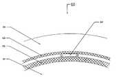
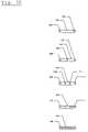
- FIG. 20depicts a cross section of a welded corrugate armor shield type high voltage cable having a holding member located in between a layer of tape and corrugated welded armor.
- FIG. 21depicts a partial cross section of the aforementioned embodiment.
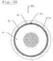
- FIG. 22depicts an embodiment of the cable having two holding members.
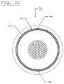
- FIG. 23depicts an embodiment of the cable having three holding members.
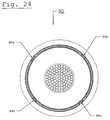
- FIG. 24depicts an embodiment of the cable having four holding members.
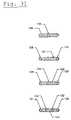
- FIG. 30depicts a variety of configurations associated with the holding members.
- FIG. 31depicts further configuration varieties for the holding member.
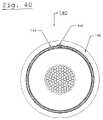
- FIG. 40is a cross section of a cable where the holding member is placed in the jacket material.
- FIG. 50is a cross section of a cable where stranded neutrals and the holding member are embedded in the jacket material.
- FIG. 60is a cross section of a cable where the holding member is placed in between the core and the layer of tape.
- FIG. 70is a cross section of a cable where the holding member replaces a stranded neutral.
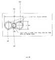
- FIG. 80is a cross-section of one embodiment of the present invention where the holding member is attached to two strength members.
- FIGS. 20 and 21shows a cross section of a welded corrugate armor shield type high voltage conductor cable ( 60 ).
- FIG. 20shows a whole cross section of the conductor cable ( 60 ), while FIG. 21 shows a partial cross-section of the conductor cable ( 60 ).
- the core ( 61 ) of the conductor cable ( 60 )is covered by a layer of insulation/bedding tape ( 62 ).
- the layer of insulation/bedding tape ( 62 )is completely or partially surrounded by a layer of corrugated welded armor ( 63 ).
- the corrugated welded armoris covered by a jacket ( 65 ).
- One holding member ( 64 )is located in between the layer of insulation/bedding tape and the corrugated welded armor ( 63 ).
- the holding member ( 64 )may have oval, circular, or like cross section shape.
- the holding membercan be placed in the conductor cable ( 60 ) in a longitudinal fashion or a helically wrapped around the core ( 61 ).
- the holding member ( 64 )can be held in place by a binder string, tape, or other connective means.
- an elongated oval shape of the holding member ( 64 )imparts crush resistance and distributes pressure. If the holding member ( 64 ) is crushed, then the optic fiber ( 66 ) within may be damaged and rendered useless. Furthermore, an oval shape distributes pressure so that there is less indentation of the insulation/bedding tape ( 62 ), which maintains the integrity of the layer of insulation/bedding tape ( 62 ).
- the holding member ( 64 )can be made from a variety of materials such as metals, composites, plastics, and/or a combination thereof.
- the holding member ( 64 )can be made of stainless steel or a combination of stainless steel and dielectric plastic.
- FIG. 22illustrates an embodiment of the welded corrugate armor shield type high voltage conductor cable ( 70 ) having two holding members ( 74 a and 74 b ) located approximately opposite of each other.
- the second holding member ( 74 b )can be located in between the layer of tape ( 72 ) and the armor ( 73 ) or can be located elsewhere in the cable ( 70 ).
- FIG. 23details another embodiment of the welded corrugate armor shield type high voltage conductor cable ( 80 ) having three holding members ( 84 a , 84 b , and 84 c ) that are approximately equidistant from each other forming a triangular shape in cross section.
- the three holding members ( 84 a , 84 b , and 84 c )can have similar or different arrangements in the cable ( 80 ).
- FIG. 24depicts an alternative embodiment of the welded corrugate armor shield type high voltage conductor cable ( 90 ) having four holding members ( 94 a , 94 b , 94 c , and 94 d ).
- This depicted embodimentalso shows an equidistant relationship between the holding members ( 94 a , 94 b , 94 c , and 94 d ), which results in a diamond shape in cross section.
- the holding members ( 94 a , 94 b , 94 c , and 94 d )can be arranged between similar or different components of the cable ( 90 ).
- FIG. 30illustrates first, second, third, fourth, and fifth cross sections of various holding members ( 100 , 101 , 102 , 103 , and 104 ), which can have variable sizes, opening sizes, and wall thickness.
- the first cross section of the holding member ( 100 )has a width that is more than two times its height.
- the first cross section of the holding memberis shaped so as to have two circular openings ( 105 , and 106 ) on opposite ends of the holding member ( 100 ).
- the first cross section of the holding member ( 100 )has a width that is more than twice the height of the holding member ( 100 ).
- the circular openings ( 105 , and 106 )are located approximately an equal distance from the sides of the holding member ( 100 ) and so that an imaginary line could be formed that passes through the diameters of the circular openings ( 105 , and 106 ).
- Such a constructionallows the holding member ( 100 ) to separate at least two fiber optic cables or at least two bundles of fiber optic cables (not shown).
- the second cross section of the holding member ( 101 )has a shape forming three circular openings ( 107 , 108 , and 109 ). Two of the circular openings ( 107 , and 108 ) are located near opposite ends of the holding member ( 101 ), while the third circular opening ( 109 ) is located near the center of the holding member ( 101 ). The distance between the third circular opening ( 109 ) and the circular openings ( 107 , and 108 ) located near the ends of the holding member ( 101 ) are approximately equal in distance. Such a construction allows the holding member ( 101 ) to separate three fiber optic cables or three bundles of fiber optic cables (not shown).
- the third cross section of the holding member ( 102 )has a shape forming four circular openings ( 110 , 111 , 112 , and 113 ). To of the circular openings ( 110 , and 111 ) are located towards the ends of the holding member ( 102 ), while the other two circular openings ( 111 , and 112 ) are located in between circular openings ( 110 , and 111 ) located towards the ends of the holding member ( 102 ). Such a construction allows the holding member ( 102 ) to separate four fiber optic cables or four bundles of fiber optic cables (not shown).
- the fourth cross section of the holding member ( 103 )has a shape forming two oval openings ( 114 , and 115 ) on opposite ends of the holding member ( 103 ).
- the oval openings ( 114 , and 115 )are located approximately an equal distance from the sides of the holding member ( 103 ) and so that an imaginary line could be drawn that passes through an equal amount of each oval opening ( 114 , and 115 ).
- Such a constructionallows the holding member ( 103 ) to separate at least two fiber optic cables or at least two bundles of fiber optic cables (not shown).
- the fifth cross section of the holding member ( 104 )has a shape forming one oval opening ( 116 ) that is proportionate to the overall cross section of the holding member ( 104 ).
- the oval opening ( 116 )allows the holding member ( 104 ) to hold at least one fiber optic cables or at least one bundle of fiber optic cables.
- first, second, third, fourth, and fifth cross section ( 100 , 101 , 102 , 103 , and 104 ) shown in FIG. 30advantageously are formed from stainless steel in the depicted embodiments.
- materialssuch as other metals, plastics, composites, and the like.
- FIG. 31depicts additional cross sections of holding members ( 120 , 121 , 122 , and 123 ).
- the first illustrated cross section of the holding member ( 120 )is oval shaped and formed from a dielectric plastic, composite, or stainless steel.
- the holding member ( 120 )supports a tube ( 124 ) formed from a material, such as stainless steel, composite, or plastic.
- the tube ( 124 )can be made from the same or different material from the holding member ( 120 ).
- the tube ( 124 ) in the depicted embodimentis located at an equal distance from the ends of the holding member ( 120 ). However, the tube ( 124 ) could be located anywhere within the holding member ( 120 ).
- the single tube ( 124 )allows at least one fiber optic cables or at least one bundle of fiber optic cables (not shown) to be placed in the holding member ( 120 ).
- the second cross section of the holding member ( 121 )is oval shaped and formed from a dielectric plastic, composite, or stainless steel.
- the holding member ( 121 )supports two tubes ( 125 and 126 ) located on opposite ends of the holding member ( 121 ).
- the tubes ( 125 , and 126 )can be made from the same or different material from the holding member ( 121 ).
- the tubes ( 125 , and 126 )are located approximately an equal distance from the sides of the holding member ( 121 ) and so that an imaginary line could be formed that passes through the diameters of the tubes ( 125 , and 126 ).
- Such a constructionallows the holding member ( 121 ) to separate at least two fiber optic cables or at least two bundles of fiber optic cables (not shown).
- the third cross section of the holding member ( 122 )is oval shaped and formed from a dielectric plastic, composite, or stainless steel.
- the holding member ( 122 )supports three tubes ( 127 , 128 , and 129 ).
- Two tubes ( 127 , and 128 )are located on opposite ends of the holding member ( 122 ).
- the third tube ( 129 )is located in between the two tubes ( 127 , and 128 ) located on opposite ends of the holding member ( 122 ).
- the tubes ( 127 , 128 , and 129 )can be made from the same or different material from the holding member ( 122 ).
- the tubes ( 127 , 128 , and 129 )can be made from different materials in respect to each other.
- the tubes ( 127 , and 128 )are located approximately an equal distance from the sides of the holding member ( 122 ) and an imaginary line could be drawn that passes through the diameters of the tubes ( 127 , 128 , and 129 ). Such a construction allows the holding member ( 122 ) to separate three fiber optic cables or three bundles of fiber optic cables (not shown).
- the fourth cross section of the holding member ( 123 )is oval shaped and formed from dielectric plastic, composite, or stainless steel.
- the holding member ( 123 )supports four tubes ( 130 , 131 , 132 , and 133 ).
- Two tubes ( 130 , and 131 )are located on opposite ends of the holding member ( 123 ).
- Two inner tubes ( 132 , and 133 )are located in between the two tubes ( 130 , and 131 ) located on opposite ends of the holding member ( 123 ).
- the tubes ( 130 , 131 , 132 , and 133 )can be made from the same or different materials than the holding member ( 123 ).
- the tubes ( 130 , 131 , 132 , and 133 )can be made from different materials in respect to each other.
- the tubes ( 130 , 131 , 132 , and 133 )are equally spaced and an imaginary line could be drawn that passes through the diameters of the tubes ( 130 , 131 , 132 , and 133 ).
- Such a constructionallows the holding member ( 123 ) to separate four fiber optic cables or three bundles of fiber optic cables.
- FIG. 40depicts an embodiment of a welded corrugate armor shield type high voltage conductor cable ( 140 ) wherein the holding member ( 144 ) is arranged longitudinally in the jacket material ( 145 ) on the exterior of the corrugated welded armor ( 143 ). This arrangement avoids twisting of the optical fibers (not shown) contained in the holding member ( 144 ). This arrangement is possible with either a core/neutral wire assembly or a core/welded assembly.
- the holding member ( 144 )is arranged longitudinally on the cable ( 140 ) and then the jacket material ( 145 ) is extruded on the assembly to effectively embed the holding member ( 144 ) into the jacket material ( 145 ).
- FIG. 50depicts an embodiment where a conductor cable ( 150 ) has a core ( 151 ) surrounded by a insulation/bedding tape ( 152 ). Concentric stranded neutrals ( 156 ) are placed on top of the insulation/bedding tape ( 152 ) and surrounded by jacket material ( 155 ). A holding member ( 154 ) is embedded in the jacket material ( 155 ).
- FIG. 60illustrates another embodiment wherein the holding member ( 164 ) is placed in between the core ( 161 ) of the conductor cable ( 160 ) and the layer of insulation/bedding tape ( 162 ). Concentric stranded neutrals ( 166 ) are placed over the layer of insulation/bedding tape ( 162 ). A jacket ( 165 ) is formed on the concentric stranded neutrals ( 166 ).
- FIG. 70illustrates an embodiment of the electrical conductor cable ( 170 ), wherein the core ( 171 ) is surrounded by a layer of insulating/bedding tape ( 172 ). Concentric stranded neutrals ( 176 ) are then placed on the exterior side of the tape ( 172 ). A holding member ( 174 ) replaces one of the concentric stranded neutrals ( 176 ). The concentric stranded neutrals ( 176 ) are then surrounded by water swellable tape ( 177 ) that is longitudinally or cigarette wrapped around the neutrals ( 176 ). A jacket ( 175 ) is formed on the exterior side of the water swellable tape ( 177 ).
- FIG. 80depicts a cross-section of one embodiment of the present invention wherein the holding member ( 602 ) contains a fiber optic ( 601 ) and is attached to two strength members ( 603 ) by jacket material ( 604 ).
- jacket material ( 604 )is polyethylene that has been extruded onto the strength member and the holding member.
- the holding memberhas at least one strength member; advantageously there are two strength members adjacent to and/or attached to the holding member and on opposite sides of the holding member.
- the present inventionis an electrical cable comprising conducting strands; a holding member containing an optic fiber located in the electrical cable; and at least one strength member adjacent the holding member providing additional protection to the optic fiber. More advantageously the present cable has two strength members adjacent the holding member. Preferably the strength member is attached to the holding member.
- the strength memberis an electrically conductive material. Preferably the electrically conductive material is copper.
- the strength member of the present inventionis attached to the holding member by polyethylene.
- the strength member and the holding memberare attached by a polyethylene jacket.
- the polyethylene jacketis semiconducting and is extruded onto the strength member and the holding member.
- the strength membersare on opposite sides of the holding member.
- the diameter of the strength memberis greater than the diameter of the holding member.
- the holding memberis a steel tube, preferably a stainless steel tube.
- a further embodiment of the present inventionis an electrical cable comprising a conducting core; a layer of insulating/bedding tape surrounding the core; a corrugated welded armor surrounding the layer of insulation/bedding tape; a first holding member arranged longitudinally along the cable between the layer of insulation/bedding tape and the corrugated welded armor; and at least one strength member adjacent the first holding member.
- the holding memberis oval shaped and forms at least one opening.
- the openingis circular or oval shaped.
- the present cablemay further comprise a second holding member arranged longitudinally along the cable.
- the second holding memberis on the opposite side of the cable from the first holding member.
- the second holding membermay be located between the layer of insulation bedding tape and the corrugated welded armor.
- the present cablemay further comprise a third holding member arranged longitudinally along the cable and may further comprise a fourth holding member arranged longitudinally along the cable.
- the cablefurther comprises an outer jacket material, wherein the holding member and strength member are arranged longitudinally along the cable in the jacket material.
- the present cablemay further comprise stranded neutrals.
- the electrical cable of the present inventionmay also comprise a conductive core; a means for holding an optic fiber; and a means for strengthening the holding means.
- the cablefurther comprises a layer of insulating bedding/tape surrounding the core; and stranded neutrals placed over the layer of insulating bedding/tape, wherein one of the stranded neutrals is replaced by the means for holding an optic fiber.
Landscapes
- Physics & Mathematics (AREA)
- General Physics & Mathematics (AREA)
- Insulated Conductors (AREA)
- Communication Cables (AREA)
Abstract
Description
Claims (14)
Priority Applications (1)
| Application Number | Priority Date | Filing Date | Title |
|---|---|---|---|
| US10/657,388US7085457B2 (en) | 2002-09-09 | 2003-09-08 | Underground electrical cable with temperature sensing means |
Applications Claiming Priority (2)
| Application Number | Priority Date | Filing Date | Title |
|---|---|---|---|
| US40913902P | 2002-09-09 | 2002-09-09 | |
| US10/657,388US7085457B2 (en) | 2002-09-09 | 2003-09-08 | Underground electrical cable with temperature sensing means |
Publications (2)
| Publication Number | Publication Date |
|---|---|
| US20040109651A1 US20040109651A1 (en) | 2004-06-10 |
| US7085457B2true US7085457B2 (en) | 2006-08-01 |
Family
ID=32474355
Family Applications (1)
| Application Number | Title | Priority Date | Filing Date |
|---|---|---|---|
| US10/657,388Expired - Fee RelatedUS7085457B2 (en) | 2002-09-09 | 2003-09-08 | Underground electrical cable with temperature sensing means |
Country Status (1)
| Country | Link |
|---|---|
| US (1) | US7085457B2 (en) |
Cited By (10)
| Publication number | Priority date | Publication date | Assignee | Title |
|---|---|---|---|---|
| US20070044992A1 (en)* | 2005-08-25 | 2007-03-01 | Bremnes Jarle J | Subsea power cable |
| US20070189678A1 (en)* | 2006-02-01 | 2007-08-16 | Shadi Khoshaba | Electronic cable signature |
| US20070237469A1 (en)* | 2006-02-17 | 2007-10-11 | Olsen Espen | Electric submarine power cable and system for direct electric heating |
| US20110067919A1 (en)* | 2009-09-24 | 2011-03-24 | Hitachi Cable, Ltd. | Device-cable assembly integrally molded with resin |
| US20110175360A1 (en)* | 2008-08-26 | 2011-07-21 | Seabased Ab | Wave-power unit |
| US20110280281A1 (en)* | 2008-12-19 | 2011-11-17 | Qhi Group Limited | Temperature Sensor |
| US8796552B2 (en) | 2009-09-14 | 2014-08-05 | Roger W. Faulkner | Underground modular high-voltage direct current electric power transmission system |
| CN105575499A (en)* | 2016-01-27 | 2016-05-11 | 安徽天龙电器线缆集团有限公司 | Polyolefin-sheathed pressure-proof cable |
| US9574949B2 (en) | 2012-02-17 | 2017-02-21 | Roctest Ltd | Automated system and method for testing the efficacy and reliability of distributed temperature sensing systems |
| US10067310B2 (en) | 2016-11-03 | 2018-09-04 | Corning Optical Communications LLC | Fiber optic drop cable assembly |
Families Citing this family (23)
| Publication number | Priority date | Publication date | Assignee | Title |
|---|---|---|---|---|
| US8331747B1 (en)* | 2008-11-07 | 2012-12-11 | Southwire Company | Non-conductive fiber optic member |
| BR112012010215A2 (en)* | 2009-10-30 | 2016-04-26 | Aker Subsea As | high voltage integrated umbilical cable |
| DE102011012681A1 (en)* | 2011-03-01 | 2012-09-06 | Hella Kgaa Hueck & Co. | High-temperature sensor for arrangement in a metal tube, in particular within an exhaust line of an internal combustion engine |
| NO333169B1 (en)* | 2011-04-19 | 2013-03-25 | Nexans | Direct electric heating cable with protection system for undersea pipeline |
| CN102507042B (en)* | 2011-11-18 | 2013-07-10 | 华中师范大学 | Method for embedding optical fiber sensor in intelligent grid power cable |
| BR112014020461B1 (en)* | 2012-02-20 | 2021-11-23 | Aker Solutions As | COOLING DEVICE FOR ELECTRIC CABLES, CONNECTION CABLES AND CABLES |
| CN102831979A (en)* | 2012-03-05 | 2012-12-19 | 韦强启 | Stranding process for carbon fiber composite core overhead conductor |
| CN103234658A (en)* | 2013-04-26 | 2013-08-07 | 国家电网公司 | High-voltage conducting wire temperature optical sensing monitoring system adopting ADSS (all-dielectric self-supporting optical fiber cable) transmission passage |
| CN104236749A (en)* | 2013-06-05 | 2014-12-24 | 天津泺佳科技有限公司 | Method for measuring temperature of cable by using optical fiber |
| TWI486560B (en)* | 2013-11-25 | 2015-06-01 | Finetek Co Ltd | Cable level temperature sensor |
| US9638586B2 (en)* | 2014-03-04 | 2017-05-02 | Underground Systems, Inc. | Dynamic wide-area earth thermal properties and earth ambient temperature determination system |
| CN103871641A (en)* | 2014-03-12 | 2014-06-18 | 无锡市曙光电缆有限公司 | Ultraviolet-proof rat-proof and ant-proof cable for subway rail traffic |
| CN104269215A (en)* | 2014-09-30 | 2015-01-07 | 四川泛华航空仪表电器有限公司 | Ignition cable shield |
| CN106469585A (en)* | 2015-08-14 | 2017-03-01 | 无锡市华美电缆有限公司 | A kind of intelligent track transport cable |
| CN106486198A (en)* | 2015-09-01 | 2017-03-08 | 无锡市群星线缆有限公司 | A kind of novel intelligent track traffic cable |
| CN105551622A (en)* | 2016-01-25 | 2016-05-04 | 安徽神州缆业集团有限公司 | Zinc-plated aluminum strip armor and voltage-resistant control electric wire |
| CN105632610A (en)* | 2016-01-27 | 2016-06-01 | 安徽天龙电器线缆集团有限公司 | Armored polyolefin sheath voltage-resistant special cable |
| CN105575500A (en)* | 2016-01-27 | 2016-05-11 | 安徽天龙电器线缆集团有限公司 | Armoring and shielding polyethylene-sheathed cable |
| JP6651886B2 (en)* | 2016-02-09 | 2020-02-19 | 日立金属株式会社 | Cable with abnormality detection function |
| CN106595900A (en)* | 2016-11-16 | 2017-04-26 | 国网山东省电力公司东营供电公司 | Extra-high-voltage cable fault monitoring system |
| US10991479B2 (en)* | 2019-01-22 | 2021-04-27 | Electric Power Research Institute, Inc. | Electric power cable |
| CN111477399A (en)* | 2020-05-18 | 2020-07-31 | 江苏东强股份有限公司 | Optical fiber temperature sensing intelligent power supply cable |
| CN111964805A (en)* | 2020-08-17 | 2020-11-20 | 重庆工程职业技术学院 | Temperature measuring device for high-temperature superconducting cable |
Citations (11)
| Publication number | Priority date | Publication date | Assignee | Title |
|---|---|---|---|---|
| US4852965A (en) | 1987-02-27 | 1989-08-01 | American Telephone And Telegraph Company At&T Bell Laboratories | Composite service and distribution communications media |
| US4952020A (en) | 1989-08-09 | 1990-08-28 | Amp Incorporated | Ribbon cable with optical fibers and electrical conductors |
| US5029974A (en) | 1990-01-22 | 1991-07-09 | Alcatel Na Cable Systems, Inc. | Unitube optical fiber cable |
| US5651081A (en) | 1994-06-10 | 1997-07-22 | Commscope, Inc. | Composite fiber optic and electrical cable and associated fabrication method |
| US5696863A (en) | 1982-08-06 | 1997-12-09 | Kleinerman; Marcos Y. | Distributed fiber optic temperature sensors and systems |
| US5917977A (en) | 1997-09-16 | 1999-06-29 | Siecor Corporation | Composite cable |
| US5991479A (en) | 1984-05-14 | 1999-11-23 | Kleinerman; Marcos Y. | Distributed fiber optic sensors and systems |
| US6049647A (en)* | 1997-09-16 | 2000-04-11 | Siecor Operations, Llc | Composite fiber optic cable |
| US6072928A (en) | 1998-07-06 | 2000-06-06 | The United States Of America As Represented By The Secretary Of Navy | Tow cable with conducting polymer jacket for measuring the temperature of a water column |
| US6236789B1 (en) | 1999-12-22 | 2001-05-22 | Pirelli Cables And Systems Llc | Composite cable for access networks |
| US20050078922A1 (en)* | 2002-07-18 | 2005-04-14 | Sanders Eugene Turner | Electrical cable with temperature sensing means and method of manufacture |
- 2003
- 2003-09-08USUS10/657,388patent/US7085457B2/ennot_activeExpired - Fee Related
Patent Citations (11)
| Publication number | Priority date | Publication date | Assignee | Title |
|---|---|---|---|---|
| US5696863A (en) | 1982-08-06 | 1997-12-09 | Kleinerman; Marcos Y. | Distributed fiber optic temperature sensors and systems |
| US5991479A (en) | 1984-05-14 | 1999-11-23 | Kleinerman; Marcos Y. | Distributed fiber optic sensors and systems |
| US4852965A (en) | 1987-02-27 | 1989-08-01 | American Telephone And Telegraph Company At&T Bell Laboratories | Composite service and distribution communications media |
| US4952020A (en) | 1989-08-09 | 1990-08-28 | Amp Incorporated | Ribbon cable with optical fibers and electrical conductors |
| US5029974A (en) | 1990-01-22 | 1991-07-09 | Alcatel Na Cable Systems, Inc. | Unitube optical fiber cable |
| US5651081A (en) | 1994-06-10 | 1997-07-22 | Commscope, Inc. | Composite fiber optic and electrical cable and associated fabrication method |
| US5917977A (en) | 1997-09-16 | 1999-06-29 | Siecor Corporation | Composite cable |
| US6049647A (en)* | 1997-09-16 | 2000-04-11 | Siecor Operations, Llc | Composite fiber optic cable |
| US6072928A (en) | 1998-07-06 | 2000-06-06 | The United States Of America As Represented By The Secretary Of Navy | Tow cable with conducting polymer jacket for measuring the temperature of a water column |
| US6236789B1 (en) | 1999-12-22 | 2001-05-22 | Pirelli Cables And Systems Llc | Composite cable for access networks |
| US20050078922A1 (en)* | 2002-07-18 | 2005-04-14 | Sanders Eugene Turner | Electrical cable with temperature sensing means and method of manufacture |
Cited By (18)
| Publication number | Priority date | Publication date | Assignee | Title |
|---|---|---|---|---|
| US20070044992A1 (en)* | 2005-08-25 | 2007-03-01 | Bremnes Jarle J | Subsea power cable |
| US7285726B2 (en)* | 2005-08-25 | 2007-10-23 | Nexans | Subsea power cable |
| US20070189678A1 (en)* | 2006-02-01 | 2007-08-16 | Shadi Khoshaba | Electronic cable signature |
| US7539379B2 (en)* | 2006-02-01 | 2009-05-26 | At&T Intellectual Property I, L.P. | Electronic cable signature |
| US20070237469A1 (en)* | 2006-02-17 | 2007-10-11 | Olsen Espen | Electric submarine power cable and system for direct electric heating |
| US7629535B2 (en)* | 2006-02-17 | 2009-12-08 | Nexans | Electric submarine power cable and system for direct electric heating |
| US20110175360A1 (en)* | 2008-08-26 | 2011-07-21 | Seabased Ab | Wave-power unit |
| US8664789B2 (en)* | 2008-08-26 | 2014-03-04 | Seabased Ab | Wave-power unit |
| US20110280281A1 (en)* | 2008-12-19 | 2011-11-17 | Qhi Group Limited | Temperature Sensor |
| US8796552B2 (en) | 2009-09-14 | 2014-08-05 | Roger W. Faulkner | Underground modular high-voltage direct current electric power transmission system |
| US9590409B2 (en) | 2009-09-14 | 2017-03-07 | Alevo International, S.A. | Underground modular high-voltage direct current electric power transmission system |
| CN102034571A (en)* | 2009-09-24 | 2011-04-27 | 日立电线株式会社 | Device-cable assembly integrally molded with resin |
| US20110067919A1 (en)* | 2009-09-24 | 2011-03-24 | Hitachi Cable, Ltd. | Device-cable assembly integrally molded with resin |
| US8242370B2 (en)* | 2009-09-24 | 2012-08-14 | Hitachi Cable, Ltd. | Device-cable assembly integrally molded with resin |
| CN102034571B (en)* | 2009-09-24 | 2014-09-03 | 日立金属株式会社 | Device-cable assembly integrally molded with resin |
| US9574949B2 (en) | 2012-02-17 | 2017-02-21 | Roctest Ltd | Automated system and method for testing the efficacy and reliability of distributed temperature sensing systems |
| CN105575499A (en)* | 2016-01-27 | 2016-05-11 | 安徽天龙电器线缆集团有限公司 | Polyolefin-sheathed pressure-proof cable |
| US10067310B2 (en) | 2016-11-03 | 2018-09-04 | Corning Optical Communications LLC | Fiber optic drop cable assembly |
Also Published As
| Publication number | Publication date |
|---|---|
| US20040109651A1 (en) | 2004-06-10 |
Similar Documents
| Publication | Publication Date | Title |
|---|---|---|
| US7085457B2 (en) | Underground electrical cable with temperature sensing means | |
| US6785450B2 (en) | Self-supporting fiber optic cable | |
| US7068893B2 (en) | Optical fiber composite electrical power cable | |
| US5495546A (en) | Fiber optic groundwire with coated fiber enclosures | |
| US4944570A (en) | Fiber optic cable having an extended elongation window | |
| US5822484A (en) | Lightweight optical groundwire | |
| WO1997030369A1 (en) | Fiber optic ground wire cable | |
| CN101311762A (en) | Modular Optical Cable Unit | |
| CN105788738A (en) | Energy efficient wire with reduced thermal knee points and the method of manufacture thereof | |
| CN101458978B (en) | High voltage electric cable for composite optical fiber | |
| US20050078922A1 (en) | Electrical cable with temperature sensing means and method of manufacture | |
| US5825957A (en) | Structure of optical fiber composite overhead ground wire applying loose tube and its fabricating method | |
| US20040124001A1 (en) | Overhead electrical cable with temperature sensing means | |
| US11942235B2 (en) | Hybrid cable for distributed power connectivity | |
| US20130183013A1 (en) | Fiber optic overhead ground wire cable and process for the manufacturing thereof | |
| RU175197U1 (en) | ELECTRO-OPTICAL CABLE | |
| US20040105635A1 (en) | Fiber optic transmission conductor and distributed temperature sensing of fiber optic transmission conductor | |
| WO1998006109A1 (en) | Electrical and optical cable | |
| US9140868B2 (en) | Submarine optical communications cables and processes for the manufacturing thereof | |
| CN107004467A (en) | Overhead communication/the electric power cable of self-supporting | |
| EP3304155B1 (en) | Aerial optical and electric cable assembly | |
| EP1293992A2 (en) | Optical-electrical hybrid cable | |
| KR100238185B1 (en) | Optical fiber composite ground wire | |
| CN120809345A (en) | Intelligent cable based on dynamic monitoring information feedback and preparation method thereof | |
| JPH03102714A (en) | Optical fiber composite underwater long body |
Legal Events
| Date | Code | Title | Description |
|---|---|---|---|
| AS | Assignment | Owner name:SOUTHWIRE COMPANY, GEORGIA Free format text:ASSIGNMENT OF ASSIGNORS INTEREST;ASSIGNORS:SANDERS, EUGENE T.;LANCASTER, MARK;WILKI, THOMAS;AND OTHERS;REEL/FRAME:014755/0852;SIGNING DATES FROM 20031017 TO 20031112 | |
| FPAY | Fee payment | Year of fee payment:4 | |
| FPAY | Fee payment | Year of fee payment:8 | |
| SULP | Surcharge for late payment | Year of fee payment:7 | |
| AS | Assignment | Owner name:BANK OF AMERICA, N.A., AS COLLATERAL AGENT, NORTH CAROLINA Free format text:SECURITY AGREEMENT;ASSIGNORS:SOUTHWIRE COMPANY, LLC;COLEMAN CABLE, INC.;TECHNOLOGY RESEARCH CORPORATION;REEL/FRAME:032251/0277 Effective date:20140211 Owner name:BANK OF AMERICA, N.A., AS COLLATERAL AGENT, NORTH Free format text:SECURITY AGREEMENT;ASSIGNORS:SOUTHWIRE COMPANY, LLC;COLEMAN CABLE, INC.;TECHNOLOGY RESEARCH CORPORATION;REEL/FRAME:032251/0277 Effective date:20140211 | |
| AS | Assignment | Owner name:WELLS FARGO BANK, NATIONAL ASSOCIATION, AS COLLATERAL AGENT, GEORGIA Free format text:GRANT OF SECURITY INTEREST IN PATENT RIGHTS;ASSIGNORS:SOUTHWIRE COMPANY, LLC;COLEMAN CABLE, INC.;TECHNOLOGY RESEARCH CORPORATION;REEL/FRAME:032308/0469 Effective date:20140211 Owner name:WELLS FARGO BANK, NATIONAL ASSOCIATION, AS COLLATE Free format text:GRANT OF SECURITY INTEREST IN PATENT RIGHTS;ASSIGNORS:SOUTHWIRE COMPANY, LLC;COLEMAN CABLE, INC.;TECHNOLOGY RESEARCH CORPORATION;REEL/FRAME:032308/0469 Effective date:20140211 | |
| AS | Assignment | Owner name:SOUTHWIRE COMPANY, LLC, DELAWARE Free format text:CHANGE OF NAME;ASSIGNOR:SOUTHWIRE COMPANY;REEL/FRAME:032641/0360 Effective date:20140205 | |
| FEPP | Fee payment procedure | Free format text:MAINTENANCE FEE REMINDER MAILED (ORIGINAL EVENT CODE: REM.) | |
| LAPS | Lapse for failure to pay maintenance fees | Free format text:PATENT EXPIRED FOR FAILURE TO PAY MAINTENANCE FEES (ORIGINAL EVENT CODE: EXP.); ENTITY STATUS OF PATENT OWNER: LARGE ENTITY | |
| STCH | Information on status: patent discontinuation | Free format text:PATENT EXPIRED DUE TO NONPAYMENT OF MAINTENANCE FEES UNDER 37 CFR 1.362 | |
| FP | Lapsed due to failure to pay maintenance fee | Effective date:20180801 | |
| AS | Assignment | Owner name:WIIP, INC., CANADA Free format text:TERMINATION AND RELEASE OF INTELLECTUAL PROPERTY SECURITY AGREEMENTS;ASSIGNOR:BANK OF AMERICA, N.A., AS AGENT;REEL/FRAME:069235/0104 Effective date:20241022 Owner name:OBI PARTNERS, LLC, GEORGIA Free format text:TERMINATION AND RELEASE OF INTELLECTUAL PROPERTY SECURITY AGREEMENTS;ASSIGNOR:BANK OF AMERICA, N.A., AS AGENT;REEL/FRAME:069235/0104 Effective date:20241022 Owner name:TOPAZ LIGHTING COMPANY LLC, GEORGIA Free format text:TERMINATION AND RELEASE OF INTELLECTUAL PROPERTY SECURITY AGREEMENTS;ASSIGNOR:BANK OF AMERICA, N.A., AS AGENT;REEL/FRAME:069235/0104 Effective date:20241022 Owner name:UNITED COPPER INDUSTRIES, LLC, DELAWARE Free format text:TERMINATION AND RELEASE OF INTELLECTUAL PROPERTY SECURITY AGREEMENTS;ASSIGNOR:BANK OF AMERICA, N.A., AS AGENT;REEL/FRAME:069235/0104 Effective date:20241022 Owner name:TAPPAN WIRE & CABLE, LLC, NEW YORK Free format text:TERMINATION AND RELEASE OF INTELLECTUAL PROPERTY SECURITY AGREEMENTS;ASSIGNOR:BANK OF AMERICA, N.A., AS AGENT;REEL/FRAME:069235/0104 Effective date:20241022 Owner name:WATTEREDGE, LLC, OHIO Free format text:TERMINATION AND RELEASE OF INTELLECTUAL PROPERTY SECURITY AGREEMENTS;ASSIGNOR:BANK OF AMERICA, N.A., AS AGENT;REEL/FRAME:069235/0104 Effective date:20241022 Owner name:NOVINIUM, LLC, GEORGIA Free format text:TERMINATION AND RELEASE OF INTELLECTUAL PROPERTY SECURITY AGREEMENTS;ASSIGNOR:BANK OF AMERICA, N.A., AS AGENT;REEL/FRAME:069235/0104 Effective date:20241022 Owner name:MADISON ELECTRIC PRODUCTS, LLC, OHIO Free format text:TERMINATION AND RELEASE OF INTELLECTUAL PROPERTY SECURITY AGREEMENTS;ASSIGNOR:BANK OF AMERICA, N.A., AS AGENT;REEL/FRAME:069235/0104 Effective date:20241022 Owner name:SUMNER MANUFACTURING COMPANY, LLC, DELAWARE Free format text:TERMINATION AND RELEASE OF INTELLECTUAL PROPERTY SECURITY AGREEMENTS;ASSIGNOR:BANK OF AMERICA, N.A., AS AGENT;REEL/FRAME:069235/0104 Effective date:20241022 Owner name:TECHNOLOGY RESEARCH, LLC (F/K/A TECHNOLOGY RESEARCH CORPORATION), FLORIDA Free format text:TERMINATION AND RELEASE OF INTELLECTUAL PROPERTY SECURITY AGREEMENTS;ASSIGNOR:BANK OF AMERICA, N.A., AS AGENT;REEL/FRAME:069235/0104 Effective date:20241022 Owner name:COLEMAN CABLE, LLC (F/K/A COLEMAN CABLE, INC.), ILLINOIS Free format text:TERMINATION AND RELEASE OF INTELLECTUAL PROPERTY SECURITY AGREEMENTS;ASSIGNOR:BANK OF AMERICA, N.A., AS AGENT;REEL/FRAME:069235/0104 Effective date:20241022 Owner name:SOUTHWIRE COMPANY, LLC, GEORGIA Free format text:TERMINATION AND RELEASE OF INTELLECTUAL PROPERTY SECURITY AGREEMENTS;ASSIGNOR:BANK OF AMERICA, N.A., AS AGENT;REEL/FRAME:069235/0104 Effective date:20241022 | |
| AS | Assignment | Owner name:SOUTHWIRE COMPANY, LLC, GEORGIA Free format text:RELEASE BY SECURED PARTY;ASSIGNOR:WELLS FARGO BANK, NATIONAL ASSOCIATION;REEL/FRAME:072299/0141 Effective date:20250730 Owner name:COLEMAN CABLE, LLC, GEORGIA Free format text:RELEASE BY SECURED PARTY;ASSIGNOR:WELLS FARGO BANK, NATIONAL ASSOCIATION;REEL/FRAME:072299/0141 Effective date:20250730 Owner name:TECHNOLOGY RESEARCH, LLC, GEORGIA Free format text:RELEASE BY SECURED PARTY;ASSIGNOR:WELLS FARGO BANK, NATIONAL ASSOCIATION;REEL/FRAME:072299/0141 Effective date:20250730 Owner name:SUMNER MANUFACTURING COMPANY, LLC, GEORGIA Free format text:RELEASE BY SECURED PARTY;ASSIGNOR:WELLS FARGO BANK, NATIONAL ASSOCIATION;REEL/FRAME:072299/0141 Effective date:20250730 Owner name:MADISON ELECTRIC PRODUCTS, LLC, GEORGIA Free format text:RELEASE BY SECURED PARTY;ASSIGNOR:WELLS FARGO BANK, NATIONAL ASSOCIATION;REEL/FRAME:072299/0141 Effective date:20250730 Owner name:NOVINIUM, LLC, GEORGIA Free format text:RELEASE BY SECURED PARTY;ASSIGNOR:WELLS FARGO BANK, NATIONAL ASSOCIATION;REEL/FRAME:072299/0141 Effective date:20250730 Owner name:NOVINIUM HOLDINGS, INC., GEORGIA Free format text:RELEASE BY SECURED PARTY;ASSIGNOR:WELLS FARGO BANK, NATIONAL ASSOCIATION;REEL/FRAME:072299/0141 Effective date:20250730 Owner name:WATTEREDGE, LLC, GEORGIA Free format text:RELEASE BY SECURED PARTY;ASSIGNOR:WELLS FARGO BANK, NATIONAL ASSOCIATION;REEL/FRAME:072299/0141 Effective date:20250730 Owner name:TAPPAN WIRE & CABLE, LLC, GEORGIA Free format text:RELEASE BY SECURED PARTY;ASSIGNOR:WELLS FARGO BANK, NATIONAL ASSOCIATION;REEL/FRAME:072299/0141 Effective date:20250730 Owner name:UNITED COPPER INDUSTRIES, LLC, GEORGIA Free format text:RELEASE BY SECURED PARTY;ASSIGNOR:WELLS FARGO BANK, NATIONAL ASSOCIATION;REEL/FRAME:072299/0141 Effective date:20250730 Owner name:TOPAZ LIGHTING COMPANY LLC, GEORGIA Free format text:RELEASE BY SECURED PARTY;ASSIGNOR:WELLS FARGO BANK, NATIONAL ASSOCIATION;REEL/FRAME:072299/0141 Effective date:20250730 Owner name:OBI PARTNERS, LLC, GEORGIA Free format text:RELEASE BY SECURED PARTY;ASSIGNOR:WELLS FARGO BANK, NATIONAL ASSOCIATION;REEL/FRAME:072299/0141 Effective date:20250730 Owner name:WIIP, INC., GEORGIA Free format text:RELEASE BY SECURED PARTY;ASSIGNOR:WELLS FARGO BANK, NATIONAL ASSOCIATION;REEL/FRAME:072299/0141 Effective date:20250730 |