US7084886B2 - Using detail-in-context lenses for accurate digital image cropping and measurement - Google Patents
Using detail-in-context lenses for accurate digital image cropping and measurementDownload PDFInfo
- Publication number
- US7084886B2 US7084886B2US10/614,754US61475403AUS7084886B2US 7084886 B2US7084886 B2US 7084886B2US 61475403 AUS61475403 AUS 61475403AUS 7084886 B2US7084886 B2US 7084886B2
- Authority
- US
- United States
- Prior art keywords
- lens
- icon
- adjusting
- original image
- points
- Prior art date
- Legal status (The legal status is an assumption and is not a legal conclusion. Google has not performed a legal analysis and makes no representation as to the accuracy of the status listed.)
- Expired - Lifetime, expires
Links
Images


Classifications
- G—PHYSICS
- G06—COMPUTING OR CALCULATING; COUNTING
- G06F—ELECTRIC DIGITAL DATA PROCESSING
- G06F3/00—Input arrangements for transferring data to be processed into a form capable of being handled by the computer; Output arrangements for transferring data from processing unit to output unit, e.g. interface arrangements
- G06F3/01—Input arrangements or combined input and output arrangements for interaction between user and computer
- G06F3/048—Interaction techniques based on graphical user interfaces [GUI]
- G06F3/0484—Interaction techniques based on graphical user interfaces [GUI] for the control of specific functions or operations, e.g. selecting or manipulating an object, an image or a displayed text element, setting a parameter value or selecting a range
- G06F3/04845—Interaction techniques based on graphical user interfaces [GUI] for the control of specific functions or operations, e.g. selecting or manipulating an object, an image or a displayed text element, setting a parameter value or selecting a range for image manipulation, e.g. dragging, rotation, expansion or change of colour
- G—PHYSICS
- G09—EDUCATION; CRYPTOGRAPHY; DISPLAY; ADVERTISING; SEALS
- G09G—ARRANGEMENTS OR CIRCUITS FOR CONTROL OF INDICATING DEVICES USING STATIC MEANS TO PRESENT VARIABLE INFORMATION
- G09G5/00—Control arrangements or circuits for visual indicators common to cathode-ray tube indicators and other visual indicators
- G09G5/08—Cursor circuits
- G—PHYSICS
- G09—EDUCATION; CRYPTOGRAPHY; DISPLAY; ADVERTISING; SEALS
- G09G—ARRANGEMENTS OR CIRCUITS FOR CONTROL OF INDICATING DEVICES USING STATIC MEANS TO PRESENT VARIABLE INFORMATION
- G09G2340/00—Aspects of display data processing
- G09G2340/04—Changes in size, position or resolution of an image
- G09G2340/045—Zooming at least part of an image, i.e. enlarging it or shrinking it
Definitions
- This inventionrelates to the field of computer graphics processing, and more specifically, to a method and system for accurate digital image cropping and measurement using detail-in-context lenses and a detail-in-context graphical user interface (“GUI”).
- GUIgraphical user interface
- a cropping operationIn computer graphics systems, users often wish to exclude portions of an image presented to them on a display screen. This operation is called “cropping”. To perform a cropping operation or crop, a user typically selects two points to define a rectangle (e.g. top left and bottom right corners) enclosing a selected portion of the original image. The portion of the original image outside of the rectangle is then excluded or cropped and an image of the selected portion alone, that is, a cropped image, is presented to the user.
- a rectanglee.g. top left and bottom right corners
- One problem with present cropping methodsis that a user may have difficulty selecting a desirable cropped image. Thus, a user may have to repeat the cropping operation several times in order to achieve the desired result.
- Kassondescribes a cropping method in which the cropped or excluded area of the image is blanked-out during the process of adjusting the rectangle defining the selected area. According to Kasson, the excluded portion of the image distracts the user and makes it more difficult to visualize the cropped image.
- a usermoves a mouse to position a cursor on the original image and depresses the mouse pushbutton to designate a first corner (x 1 , y 1 ) of the initially desired rectangular cropped image. The mouse is then manually moved and the sequentially updated position of the cursor instantaneously defines a second corner (x 2 , y 2 ) diagonally opposite the first corner.
- any two of x 1 , y 1 , x 2 and y 2can be updated by positioning the cursor over one of the four corners of the rectangular boundary of the current cropped image, depressing the mouse pushbutton, and holding it down while the cursor is moved.
- Cariffe, et al.describe a cropping method in which after the cropped image has been formed and is displayed in a new window, the window containing the original image is also maintained and may be viewed concurrently with the cropped image. Moreover, the window containing the original image is preferably automatically minimized, that is, reduced in size to what is called an “iconified” version of the original, but may subsequently be restored to full size. If subsequent comparison by the user of both the original and cropped images side-by-side show an unwanted result, the cropping operation may then be repeated on the image in the original image window, which preferably does not get modified in any way by single or multiple sequential cropping operations.
- a method for cropping a computer generated original image on a displaycomprising the steps of: adjusting a user-selected movable boundary on the original image to define a cropped image within the boundary, the boundary defined by two or more points on the original image; and, distorting the original image in regions surrounding the points, whereby the boundary is accurately positioned for cropping.
- the step of distortingfurther includes the steps of: creating a lens surface for one or more of the regions; and, transforming the original image by applying a distortion function defining the lens surface to the original image.
- the step of creatingfurther includes the step of displaying a GUI over one or more of the regions for adjusting the lens surface.
- the lens surfaceincludes a focal region and a base region and the GUI includes: a slide bar icon for adjusting a magnification for the lens surface; a slide bar icon for adjusting a degree of scooping for the lens surface; a bounding rectangle icon with at least one handle icon for adjusting a size and a shape for the focal region; a bounding rectangle icon with at least one handle icon for adjusting a size and a shape for the base region; a move icon for adjusting a location for the lens surface on the boundary; a pickup icon for adjusting a location for the base region within the original image; and, a fold icon for adjusting a location for the focal region relative to the base region.
- the adjustingis performed by moving a cursor on the display with a pointing device, the cursor is an icon, the pointing device is a mouse, and the movable boundary is a polygon.
- the original imagehas one or more layers
- the regionshave a predetermined selection of these layers
- the cropped imagehas a predetermined selection of these layers.
- a usercan view a large area (i.e. outside the lenses) while focusing in on smaller areas (i.e. inside the focal regions of the lenses) surrounding the selected points. This makes it possible for a user to perform accurate cropping without losing visibility or context of the portion of the original image surrounding the cropped area.
- a method for measuring within a computer generated original image on a displaycomprising the steps of: adjusting a user-selected movable line segment on the original image to define points on the original image for measuring between; and, distorting the original image in regions surrounding the points, whereby the points are accurately positioned for measuring.
- the step of distortingfurther includes the steps of: creating a lens surface for one or more of the regions; and, transforming the original image by applying a distortion function defining the lens surface to the original image.
- the step of creatingfurther includes the step of displaying a GUI over one or more of the regions for adjusting the lens surface.
- the lens surfaceincludes a focal region and a base region and the GUI includes: a slide bar icon for adjusting a magnification for the lens surface; a slide bar icon for adjusting a degree of scooping for the lens surface; a bounding rectangle icon with at least one handle icon for adjusting a size and a shape for the focal region; a bounding rectangle icon with at least one handle icon for adjusting a size and a shape for the base region; a move icon for adjusting a location for the lens surface on the boundary; a pickup icon for adjusting a location for the base region within the original image; and, a fold icon for adjusting a location for the focal region relative to the base region.
- the adjustingis performed by moving a cursor on the display with a pointing device, the cursor is an icon, the pointing device is a mouse, and the line segment is a straight line.
- a usercan view a large area (i.e. outside the lenses) while focusing in on smaller areas (i.e. inside the focal regions of the lenses) surrounding the selected points.
- Thismakes it possible for a user to perform accurate measuring without losing visibility or context of the portion of the original image surrounding the points.
- the selected pointsare contained within the focal region of each lens, which may be displayed at a higher resolution that the surrounding presentation, the measured value may be determined more accurately.
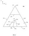
- FIG. 1is a graphical representation of the geometry for constructing a three-dimensional (3D) perspective viewing frustum, relative to an x, y, z coordinate system, in accordance with known elastic presentation space graphics technology;
- FIG. 2is a graphical representation of the geometry of a presentation in accordance with known elastic presentation space graphics technology
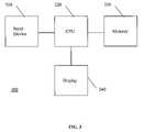
- FIG. 3is a block diagram illustrating a data processing system adapted for implementing an embodiment of the invention
- FIG. 4a partial screen capture illustrating a GUI having lens control elements for user interaction with detail-in-context data presentations in accordance with an embodiment of the invention
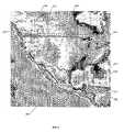
- FIG. 5is a screen capture illustrating a presentation having two detail-in-context lenses and associated GUIs for defining the corners of a bounding rectangle GUI for cropping an original digital image or representation in accordance with an embodiment of the invention
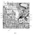
- FIG. 6is a screen capture illustrating a presentation having detail-in-context lenses, associated GUIs, and a bounding rectangle GUI or icon for cropping an original digital image or representation to produce a cropped image in accordance with an embodiment of the invention
- FIG. 7is a screen capture illustrating a presentation having detail-in-context lenses and associated GUIs for selecting points between which to measure in an original digital image or representation in accordance with an embodiment of the invention
- FIG. 8is a screen capture illustrating a presentation having two detail-in-context lenses, associated GUIs, and a measuring tool GUI for displaying the measurement between selected points in an original digital image or representation in accordance with an embodiment of the invention
- FIG. 9is a screen capture illustrating a presentation having a single detail-in-context lens and associated GUI for defining the corners of a bounding rectangle GUI for cropping an original digital image or representation in accordance with an embodiment of the invention
- FIG. 10is a screen capture illustrating a presentation having a single detail-in-context lens, an associated GUI, and a bounding rectangle GUI or icon for cropping an original digital image or representation to produce a cropped image in accordance with an embodiment of the invention
- FIG. 11Ais a screen capture illustrating a presentation having a single detail-in-context lens and an associated GUI for selecting points between which to measure in an original digital image or representation in accordance with an embodiment of the invention
- FIG. 11Bis a screen capture illustrating a presentation having a single detail-in-context lens, an associated GUI, and a measuring tool GUI for displaying the measurement between two selected points in an original digital image or representation in accordance with an embodiment of the invention
- FIG. 11Cis a screen capture illustrating a presentation having a single detail-in-context lens, an associated GUI, and a measuring tool GUI for displaying the measurement between multiple selected points in an original digital image or representation in accordance with an embodiment of the invention
- FIG. 12is a flow chart illustrating a method for cropping a computer generated original image on a display in accordance with an embodiment of the invention.
- FIG. 13is a flow chart illustrating a method for measuring within a computer generated original image on a display in accordance with an embodiment of the invention.
- data processing systemis used herein to refer to any machine for processing data, including the computer systems and network arrangements described herein.
- the “screen real estate problem” mentioned abovegenerally arises whenever large amounts of information are to be displayed on a display screen of limited size.
- well-known tools to address this probleminclude panning and zooming. While these tools are suitable for a large number of visual display applications, they become less effective where sections of the visual information are spatially related, such as in maps, three-dimensional representations, and newspapers, for example. In this type of information display, panning and zooming are not as effective as much of the context of the panned or zoomed display may be hidden.
- Detail-in-contextis the magnification of a particular region-of-interest (the “focal region” or “detail”) in a data presentation while preserving visibility of the surrounding information (the “context”).
- This techniquehas applicability to the display of large surface area media (e.g. digital maps) on computer screens of variable size including graphics workstations, laptop computers, personal digital assistants (“PDAs”), and cell phones.
- PDAspersonal digital assistants
- a representationis a formal system, or mapping, for specifying raw information or data that is stored in a computer or data processing system.
- a digital map of a cityis a representation of raw data including street names and the relative geographic location of streets and utilities. Such a representation may be displayed visually on a computer screen or printed on paper.
- a presentationis a spatial organization of a given representation that is appropriate for the task at hand.
- a presentation of a representationorganizes such things as the point of view and the relative emphasis of different parts or regions of the representation. For example, a digital map of a city may be presented with a region magnified to reveal street names.
- a detail-in-context presentationmay be considered as a distorted view (or distortion) of a portion of the original representation where the distortion is the result of the application of a “lens” like distortion function to the original representation.
- EPSElastic Presentation Space
- PDTPliable Display Technology
- detail-in-context data presentationsare characterized by magnification of areas of an image where detail is desired, in combination with compression of a restricted range of areas of the remaining information (i.e. the context), the result typically giving the appearance of a lens having been applied to the display surface.
- points in a representationare displaced in three dimensions and a perspective projection is used to display the points on a two-dimensional presentation display.
- the resulting presentationappears to be three-dimensional.
- the lens transformationappears to have stretched the continuous surface in a third dimension.
- EPS graphics technologya two-dimensional visual representation is placed onto a surface; this surface is placed in three-dimensional space; the surface, containing the representation, is viewed through perspective projection; and the surface is manipulated to effect the reorganization of image details.
- the presentation transformationis separated into two steps: surface manipulation or distortion and perspective projection.
- FIG. 1is a graphical representation 100 of the geometry for constructing a three-dimensional (“3D”) perspective viewing frustum 220 , relative to an x, y, z coordinate system, in accordance with known elastic presentation space (EPS) graphics technology.
- EPSelastic presentation space
- 2Dtwo-dimensional
- EPSmagnification of regions of interest and the accompanying compression of the contextual region to accommodate this change in scale are produced by the movement of regions of the surface towards the viewpoint (“VP”) 240 located at the apex of the pyramidal shape 220 containing the frustum.
- the process of projecting these transformed layouts via a perspective projectionresults in a new 2D layout which includes the zoomed and compressed regions.
- the use of the third dimension and perspective distortion to provide magnification in EPSprovides a meaningful metaphor for the process of distorting the information presentation surface.
- the 3D manipulation of the information presentation surface in such a systemis an intermediate step in the process of creating a new 2D layout of the information.
- FIG. 2is a graphical representation 200 of the geometry of a presentation in accordance with known EPS graphics technology.
- EPS graphics technologyemploys viewer-aligned perspective projections to produce detail-in-context presentations in a reference view plane 201 which may be viewed on a display.
- Undistorted 2D data pointsare located in a basal plane 210 of a 3D perspective viewing volume or frustum 220 which is defined by extreme rays 221 and 222 and the basal plane 210 .
- the VP 240is generally located above the centre point of the basal plane 210 and reference view plane (“RVP”) 201 . Points in the basal plane 210 are displaced upward onto a distorted surface 230 which is defined by a general 3D distortion function (i.e.
- the direction of the viewer-aligned perspective projection corresponding to the distorted surface 230is indicated by the line FPo-FP 231 drawn from a point FPo 232 in the basal plane 210 through the point FP 233 which corresponds to the focus or focal region or focal point of the distorted surface 230 .
- EPSis applicable to multidimensional data and is well suited to implementation on a computer for dynamic detail-in-context display on an electronic display surface such as a monitor.
- EPSis typically characterized by magnification of areas of an image where detail is desired 233 , in combination with compression of a restricted range of areas of the remaining information (i.e. the context) 234 , the end result typically giving the appearance of a lens 230 having been applied to the display surface.
- the areas of the lens 230 where compression occursmay be referred to as the “shoulder” 234 of the lens 230 .
- the area of the representation transformed by the lensmay be referred to as the “lensed area”.
- the lensed areathus includes the focal region and the shoulder.
- the source image or representation to be viewedis located in the basal plane 210 .
- Magnification 233 and compression 234are achieved through elevating elements of the source image relative to the basal plane 210 , and then projecting the resultant distorted surface onto the reference view plane 201 .
- EPSperforms detail-in-context presentation of n-dimensional data through the use of a procedure wherein the data is mapped into a region in an (n+1) dimensional space, manipulated through perspective projections in the (n+1) dimensional space, and then finally transformed back into n-dimensional space for presentation.
- EPShas numerous advantages over conventional zoom, pan, and scroll technologies, including the capability of preserving the visibility of information outside 234 the local region of interest 233 .
- EPScan be implemented through the projection of an image onto a reference plane 201 in the following manner.
- the source image or representationis located on a basal plane 210 , and those regions of interest 233 of the image for which magnification is desired are elevated so as to move them closer to a reference plane situated between the reference viewpoint 240 and the reference view plane 201 .
- Magnification of the focal region 233 closest to the RVP 201varies inversely with distance from the RVP 201 . As shown in FIGS.
- compression of regions 234 outside the focal region 233is a function of both distance from the RVP 201 , and the gradient of the function describing the vertical distance from the RVP 201 with respect to horizontal distance from the focal region 233 .
- the resultant combination of magnification 233 and compression 234 of the image as seen from the reference viewpoint 240results in a lens-like effect similar to that of a magnifying glass applied to the image.
- the various functions used to vary the magnification and compression of the source image via vertical displacement from the basal plane 210are described as lenses, lens types, or lens functions. Lens functions that describe basic lens types with point and circular focal regions, as well as certain more complex lenses and advanced capabilities such as folding, have previously been described by Carpendale.
- FIG. 3is a block diagram of a data processing system 300 adapted to implement an embodiment of the invention.
- the data processing systemis suitable for implementing EPS technology, for displaying detail-in-context presentations of representations, and for cropping representations in conjunction with a detail-in-context graphical user interface (“GUI”) 400 , as described below.
- the data processing system 300includes an input device 310 , a central processing unit or CPU 320 , memory 330 , and a display 340 .
- the input device 310may include a keyboard, mouse, trackball, or similar device.
- the CPU 320may include dedicated coprocessors and memory devices.
- the memory 330may include RAM, ROM, databases, or disk devices.
- the display 340may include a computer screen, terminal device, or a hardcopy producing output device such as a printer or plotter.
- the data processing system 300has stored therein data representing sequences of instructions which when executed cause the method described herein to be performed.
- the data processing system 300may contain additional software and hardware a description of which is not necessary for understanding the invention.
- GUI with Lens Control ElementsAs mentioned, detail-in-context presentations of data using techniques such as pliable surfaces, as described by Carpendale, are useful in presenting large amounts of information on limited-size display surfaces. Detail-in-context views allow magnification of a particular region-of-interest (the “focal region”) 233 in a data presentation while preserving visibility of the surrounding information 210 .
- a GUI 400is described having lens control elements that can be implemented in software and applied to the cropping and measurement of representations and to the control of detail-in-context data presentations. The software can be loaded into and run by the data processing system 300 of FIG. 3 .
- FIG. 4is a partial screen capture illustrating a GUI 400 having lens control elements for user interaction with detail-in-context data presentations in accordance with an embodiment of the invention.
- Detail-in-context data presentationsare characterized by magnification of areas of an image where detail is desired, in combination with compression of a restricted range of areas of the remaining information (i.e. the context), the end result typically giving the appearance of a lens having been applied to the display screen surface.
- This lens 410includes a “focal region” 420 having high magnification, a surrounding “shoulder region” 430 where information is typically visibly compressed, and a “base” 412 surrounding the shoulder region 430 and defining the extent of the lens 410 .
- FIG. 4is a partial screen capture illustrating a GUI 400 having lens control elements for user interaction with detail-in-context data presentations in accordance with an embodiment of the invention.
- Detail-in-context data presentationsare characterized by magnification of areas of an image where detail is desired, in combination with compression of
- the lens 410is shown with a circular shaped base 412 (or outline) and with a focal region 420 lying near the center of the lens 410 .
- the lens 410 and focal region 420may have any desired shape.
- the lenses 510 , 511have a pyramid shape with flat tops 520 , 521 and trapezoidal shoulders 530 , 531 .
- the base of the lens 412may be coextensive with the focal region 420 .
- the GUI 400has lens control elements that, in combination, provide for the interactive control of the lens 410 , 510 , 511 .
- the effective control of the characteristics of the lens 410 by a useri.e. dynamic interaction with a detail-in-context lens
- one or more of these lens control elementsmay be made visible to the user on the display surface 340 by appearing as overlay icons on the lens 410 .
- Interaction with each elementis performed via the motion of an input or pointing device 310 (e.g. mouse), with the motion resulting in an appropriate change in the corresponding lens characteristic.
- selection of which lens control element is actively controlled by the motion of the pointing device 310 at any given timeis determined by the proximity of the icon representing the pointing device 310 (e.g. cursor) on the display surface 340 to the appropriate component of the lens 410 .
- the icon representing the pointing device 310e.g. cursor
- “dragging” of the pointing device at the periphery of the bounding rectangle of the lens base 412causes a corresponding change in the size of the lens 410 (i.e. “resizing”).
- the GUI 400provides the user with a visual representation of which lens control element is being adjusted through the display of one or more corresponding icons.
- a mouse 310controls the position of a cursor icon 401 that is displayed on the display screen 340 .
- the cursor 401is moved by moving the mouse 310 over a flat surface, such as the top of a desk, in the desired direction of movement of the cursor 401 .
- a flat surfacesuch as the top of a desk
- the two-dimensional movement of the mouse 310 on the flat surfacetranslates into a corresponding two-dimensional movement of the cursor 401 on the display screen 340 .
- a mouse 310typically has one or more finger actuated control buttons (i.e. mouse buttons). While the mouse buttons can be used for different functions such as selecting a menu option pointed at by the cursor 401 , the disclosed invention may use a single mouse button to “select” a lens 410 and to trace the movement of the cursor 401 along a desired path. Specifically, to select a lens 410 , the cursor 401 is first located within the extent of the lens 410 . In other words, the cursor 401 is “pointed” at the lens 410 . Next, the mouse button is depressed and released. That is, the mouse button is “clicked”. Selection is thus a point and click operation.
- the mouse buttonis depressed and released. That is, the mouse button is “clicked”. Selection is thus a point and click operation.
- the cursor 401is located at the desired starting location, the mouse button is depressed to signal the computer 320 to activate a lens control element, and the mouse 310 is moved while maintaining the button depressed. After the desired path has been traced, the mouse button is released.
- This procedureis often referred to as “clicking” and “dragging” (i.e. a click and drag operation). It will be understood that a predetermined key on a keyboard 310 could also be used to activate a mouse click or drag.
- clickingwill refer to the depression of a mouse button indicating a selection by the user and the term “dragging” will refer to the subsequent motion of the mouse 310 and cursor 401 without the release of the mouse button.
- the GUI 400may include the following lens control elements: move, pickup, resize base, resize focus, fold, magnify, and scoop. Each of these lens control elements has at least one lens control icon or alternate cursor icon associated with it.
- the following lens control iconsmay be displayed over the lens 410 : pickup icon 450 , base outline icon 412 , base bounding rectangle icon 411 , focal region bounding rectangle icon 421 , handle icons 481 , 482 , 491 , magnify slide bar icon 440 , and scoop slide bar icon 540 (see FIG. 5 ).
- these iconsare displayed simultaneously after selection of the lens 410 .
- an alternate cursor icon 460 , 470 , 480 , 490may be displayed over the lens 410 to replace the cursor 401 or may be displayed in combination with the cursor 401 .
- bounding rectangle icons 411 , 421are displayed surrounding the base 412 and focal region 420 of the selected lens 410 to indicate that the lens 410 has been selected.
- bounding rectangles 411 , 421one might view them as glass windows enclosing the lens base 412 and focal region 420 , respectively.
- the bounding rectangles 411 , 421include handle icons 481 , 482 , 491 allowing for direct manipulation of the enclosed base 412 and focal region 420 as will be explained below.
- the bounding rectangles 411 , 421not only inform the user that the lens 410 has been selected, but also provide the user with indications as to what manipulation operations might be possible for the selected lens 410 though use of the displayed handles 481 , 482 , 491 .
- a bounding region having a shape other than generally rectangularSuch a bounding region could be of any of a great number of shapes including oblong, oval, ovoid, conical, cubic, cylindrical, polyhedral, spherical, etc.
- the cursor 401provides a visual cue indicating the nature of an available lens control element. As such, the cursor 401 will generally change in form by simply pointing to a different lens control icon 450 , 412 , 411 , 421 , 481 , 482 , 491 , 440 , 540 . For example, when resizing the base 412 of a lens 410 using a corner handle 491 , the cursor 401 will change form to a resize icon 490 once it is pointed at (i.e. positioned over) the corner handle 491 . The cursor 401 will remain in the form of the resize icon 490 until the cursor 401 has been moved away from the corner handle 491 .
- MoveLateral movement of a lens 410 is provided by the move lens control element of the GUI 400 .
- This functionalityis accomplished by the user first selecting the lens 410 , 510 , 511 through a point and click operation. Then, the user points to a point within the lens 410 that is other than a point lying on a lens control icon 450 , 412 , 411 , 421 , 481 , 482 , 491 , 440 , 540 .
- a move icon 460is displayed over the lens 410 to replace the cursor 401 or may be displayed in combination with the cursor 401 .
- the move icon 460not only informs the user that the lens 410 may be moved, but also provides the user with indications as to what movement operations are possible for the selected lens 410 .
- the move icon 460may include arrowheads indicating up, down, left, and right motion.
- the lens 410is moved by a click and drag operation in which the user clicks and drags the lens 410 to the desired position on the screen 340 and then releases the mouse button 310 .
- the lens 410is locked in its new position until a further pickup and move operation is performed.
- a lens 410is also provided by the pickup lens control element of the GUI. This functionality is accomplished by the user first selecting the lens 410 through a point and click operation. As mentioned above, when the lens 410 is selected a pickup icon 450 is displayed over the lens 410 near the centre of the lens 410 . Typically, the pickup icon 450 will be a crosshairs. In addition, a base outline 412 is displayed over the lens 410 representing the base 412 of the lens 410 . The crosshairs 450 and lens outline 412 not only inform the user that the lens has been selected, but also provides the user with an indication as to the pickup operation that is possible for the selected lens 410 . Next, the user points at the crosshairs 450 with the cursor 401 .
- the lens outline 412is moved by a click and drag operation in which the user clicks and drags the crosshairs 450 to the desired position on the screen 340 and then releases the mouse button 310 .
- the full lens 410is then moved to the new position and is locked there until a further pickup operation is performed.
- Resizing of the base 412 (or outline) of a lens 410is provided by the resize base lens control element of the GUI. After the lens 410 is selected, a bounding rectangle icon 411 is displayed surrounding the base 412 .
- the bounding rectangle 411includes handles 491 . These handles 491 can be used to stretch the base 412 taller or shorter, wider or narrower, or proportionally larger or smaller.
- the corner handles 491will keep the proportions the same while changing the size.
- the middle handles(not shown) will make the base 412 taller or shorter, wider or narrower. Resizing the base 412 by the corner handles 491 will keep the base 412 in proportion. Resizing the base 412 by the middle handles (not shown) will change the proportions of the base 412 .
- the middle handleschange the aspect ratio of the base 412 (i.e. the ratio between the height and the width of the bounding rectangle 411 of the base 412 ).
- a resize icon 490may be displayed over the handle 491 to replace the cursor 401 or may be displayed in combination with the cursor 401 .
- the resize icon 490not only informs the user that the handle 491 may be selected, but also provides the user with indications as to the resizing operations that are possible with the selected handle.
- the resize icon 490 for a corner handle 491may include arrows indicating proportional resizing.
- the resize icon (not shown) for a middle handlemay include arrows indicating width resizing or height resizing.
- the bounding rectangle 421includes handles 481 , 482 . These handles 481 , 482 can be used to stretch the focal region 420 taller or shorter, wider or narrower, or proportionally larger or smaller.
- the corner handles 481will keep the proportions the same while changing the size.
- the middle handles 482will make the focal region 420 taller or shorter, wider or narrower. Resizing the focal region 420 by the corner handles 481 will keep the focal region 420 in proportion.
- the middle handles 482will change the proportions of the focal region 420 . That is, the middle handles 482 change the aspect ratio of the focal region 420 (i.e. the ratio between the height and the width of the bounding rectangle 421 of the focal region 420 ).
- a resize icon 480may be displayed over the handle 481 , 482 to replace the cursor 401 or may be displayed in combination with the cursor 401 .
- the resize icon 480not only informs the user that a handle 481 , 482 may be selected, but also provides the user with indications as to the resizing operations that are possible with the selected handle.
- the resize icon 480 for a corner handle 481may include arrows indicating proportional resizing.
- the resize icon 480 for a middle handle 482may include arrows indicating width resizing or height resizing.
- Folding of the focal region 420 of a lens 410is provided by the fold control element of the GUI.
- control of the degree and direction of foldingi.e. skewing of the viewer aligned vector 231 as described by Carpendale
- the direction of foldingis determined by the direction in which the point 471 is dragged.
- the degree of foldingis determined by the magnitude of the translation of the cursor 401 during the drag.
- the direction and degree of foldingcorresponds to the relative displacement of the focus 420 with respect to the lens base 410 . In other words, and referring to FIG.
- the direction and degree of foldingcorresponds to the displacement of the point FP 233 relative to the point FPo 232 , where the vector joining the points FPo 232 and FP 233 defines the viewer aligned vector 231 .
- a bounding rectangle icon 421is displayed surrounding the focal region 420 .
- the bounding rectangle 421includes handles 481 , 482 .
- a fold icon 470may be displayed over the point 471 to replace the cursor 401 or may be displayed in combination with the cursor 401 .
- the fold icon 470not only informs the user that a point 471 on the bounding rectangle 421 may be selected, but also provides the user with indications as to what fold operations are possible.
- the fold icon 470may include arrowheads indicating up, down, left, and right motion.
- Magnify. Magnification of the lens 410is provided by the magnify lens control element of the GUI. After the lens 410 is selected, the magnify control is presented to the user as a slide bar icon 440 near or adjacent to the lens 410 and typically to one side of the lens 410 . Sliding the bar 441 of the slide bar 440 results in a proportional change in the magnification of the lens 410 .
- the slide bar 440not only informs the user that magnification of the lens 410 may be selected, but also provides the user with an indication as to what level of magnification is possible.
- the slide bar 440includes a bar 441 that may be slid up and down, or left and right, to adjust and indicate the level of magnification.
- the userwould click on the bar 441 of the slide bar 440 and drag in the direction of desired magnification level. Once the desired level of magnification is reached, the user would release the mouse button 310 .
- the lens 410is then locked with the selected magnification until a further magnification operation is performed.
- the focal region 420is an area of the lens 410 having constant magnification (i.e. if the focal region is a plane). Again referring to FIGS. 1 and 2 , magnification of the focal region 420 , 233 varies inversely with the distance from the focal region 420 , 233 to the reference view plane (RVP) 201 .
- RVPreference view plane
- Magnification of areas lying in the shoulder region 430 of the lens 410also varies inversely with their distance from the RVP 201 .
- magnification of areas lying in the shoulder region 430will range from unity at the base 412 to the level of magnification of the focal region 420 .
- the concavity or “scoop” of the shoulder region 430 of the lens 410is provided by the scoop lens control element of the GUI. After the lens 410 is selected, the scoop control is presented to the user as a slide bar icon 540 (see FIG. 5 ) near or adjacent to the lens 410 , 510 , 511 and typically below the lens 410 . Sliding the bar 541 of the slide bar 540 results in a proportional change in the concavity or scoop of the shoulder region 430 of the lens 410 .
- the slide bar 540not only informs the user that the shape of the shoulder region 430 of the lens 410 may be selected, but also provides the user with an indication as to what degree of shaping is possible.
- the slide bar 540includes a bar 541 that may be slid left and right, or up and down, to adjust and indicate the degree of scooping.
- the userwould click on the bar 541 of the slide bar 540 and drag in the direction of desired scooping degree. Once the desired degree of scooping is reached, the user would release the mouse button 310 . The lens 410 is then locked with the selected scoop until a further scooping operation is performed.
- a usermay choose to hide one or more lens control icons 450 , 412 , 411 , 421 , 481 , 482 , 491 , 440 , 540 shown in FIGS. 4 and 5 from view so as not to impede the user's view of the image within the lens 410 .
- Thismay be helpful, for example, during a move operation.
- a usermay select this option through means such as a menu or lens property dialog box.
- detail-in-context data viewing techniquesare applied to the cropping and measurement of digital image presentations.
- Detail-in-context data viewing techniquesallow a user to view multiple levels of detail or resolution on one display 340 .
- the appearance of the data display or presentationis that of one or more virtual lens showing detail 233 within the context of a larger area view 210 .
- Using multiple lenses in detail-in-context data presentationsmay be used to compare two regions of interest at the same time. Folding enhances this comparison by allowing the user to pull the regions of interest closer together.
- multiple detail-in-context lensesmay be used to accurately crop digital images.
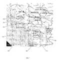
- FIG. 5is a screen capture illustrating a presentation 500 having two detail-in-context lenses 510 , 511 and associated GUIs 501 , 502 for defining the corners of a bounding rectangle GUI for cropping an original digital image or representation in accordance with an embodiment of the invention.
- the original image to be croppedis a map of North America.
- a userdefines a first lens 510 over Washington State using a first GUI 501 and a second lens 511 over Florida using a second GUI 502 .
- the lenses 510 , 511may be introduced to the original image to form the illustrated presentation through the use of a pull-down menu selection, tool bar icon, etc.
- the lenses 510 , 511are positioned at what will be the top left and bottom right corners of a bounding rectangle that will be used to define the cropped image.
- lens control elements for each GUI 501 , 502such as move, pickup, resize base, resize focus, fold, and magnify as described above, the user adjusts each lens 510 , 511 to accurately select a point or corner for the creation of a bounding rectangle for cropping.
- Each selected pointmay be indicated on in the presentation with a crosshairs icon 450 , for example.
- the usermay magnify the focal region 520 , 521 of each lens 510 , 511 to pixel quality resolution making it easy to view, for example, the point where the boarders of Washington State and Canada meet in the first lens 510 and the point where land ends at the coast of Florida in the second lens 511 .
- FIG. 6is a screen capture illustrating a presentation 600 having detail-in-context lenses 510 , 511 , associated GUIs 501 , 502 , and a bounding rectangle GUI or icon 610 for cropping an original digital image or representation to produce a cropped image 640 in accordance with an embodiment of the invention.
- the usermay use an existing tool to crop the presentation 600 to produce a cropped image 640 .
- the userhas defined an area with a bounding rectangle GUI 610 .
- the bounding rectangle GUI 610defining an area for the cropped image 640 , may also be displaced or distorted by the lenses 510 , 511 , however, in FIG. 6 , this is not shown.
- the resultant cropped image 640may be presented with or without lens distortions 510 , 511 .
- the data processing system 300employs EPS techniques with an input device 310 and GUIs 501 , 502 , 610 for selecting points 620 , 630 to define a cropped image 640 for display to a user on a display screen 340 .
- Data representing an original image or representationis received by the CPU 320 of the data processing system 300 .
- the CPU 320processes the data in accordance with instructions received from the user via an input device 310 and GUIs 501 , 502 to produce a detail-in-context presentation 500 .
- the presentation 500is presented to the user on a display screen 340 .
- the CPU 320may apply a transformation to the shoulder regions 530 , 531 surrounding the regions-of-interest 520 , 521 to affect blending or folding in accordance with EPS technology.
- the transformationmay map the regions-of-interest 520 , 521 and/or shoulder regions 530 , 531 to a predefined lens surface, defined by a transformation or distortion function and having a variety of shapes, using EPS techniques.
- the lens 510 , 511may be simply coextensive with the regions-of-interest 520 , 521 . Blending and folding of lenses in detail-in-context presentations are described in U.S. patent application Publication No. 2002/0044154 which is incorporated herein by reference.
- the lens control elements of the GUIs 501 , 502are adjusted by the user via an input device 310 to control the characteristics of the lenses 510 , 511 in the detail-in-context presentation 500 .
- an input device 310such as a mouse
- a useradjusts parameters of the lens 510 , 511 using icons and scroll bars of GUIs 501 , 502 that are displayed over the lens on the display screen 340 .
- the usermay also adjust parameters of the image of the full scene 500 .
- Signals representing input device 310 movements and selectionsare transmitted to the CPU 320 of the data processing system 300 where they are translated into instructions for lens control.
- the bounding rectangle GUI 610indicates the selected area for the cropped image 640 .
- the usercan change the location of the corners 620 , 630 (or regions-of-interest 520 , 521 ) in the presentation 600 .
- the bounding rectangle GUI 610may be presented automatically upon placement of the lenses 510 , 511 or its presentation may be selected using a pull-down menu selection, tool bar, crop icon, etc.
- the usercan decide whether or not the currently cropped image 640 accurately captures the desired area of the presentation 600 . If the user is satisfied with the cropped image 640 , the user may select the cropped image 640 by double clicking within the bounding rectangle GUI 610 or with a pull-down menu selection, crop icon, crop button, etc. The current cropped image 640 is thus selected for further processing, such as inclusion into a document being concurrently displayed in another window or replacement of the original presentation with the cropped image 640 . Clicking on one of the corners 620 , 630 will select the corresponding lens 510 , 511 and GUI 501 , 502 for adjustment. If the user is dissatisfied with the current cropped image 640 , then the double clicking operation is avoided and instead a corner 620 , 630 of the bounding rectangle GUI 610 can be moved to show a different cropped image 640 .
- a usercan view a large area 600 (i.e. outside the lenses 510 , 511 ) while focusing in on smaller areas 520 , 521 (i.e. inside the focal regions 520 , 521 of the lenses 510 , 511 ) surrounding the selected points 620 , 630 .
- Thismakes it possible for a user to perform accurate cropping without losing visibility or context of the portion of the original image surrounding the cropped area 640 .
- two lenses 510 , 511are added to the presentation 500 before the bounding rectangle GUI 610 is activated.
- the lenses 510 , 511 and bounding rectangle GUI 610can be combined. That is, the user may first add a lens 510 to a presentation 500 or the user may move a pre-existing lens into place at, say, the top left corner point 620 in FIG. 6 . At this stage, before the second point 630 is selected, the bounding rectangle GUI 610 is activated. Now, to select the second point 630 , the bottom right corner 650 of the bounding rectangle GUI 610 is moved (e.g. with a click and drag operation) by the user. As the bottom right corner 650 of the bounding rectangle GUI 610 is dragged, the second lens 511 is presented over and moves with the corner 650 . This facilitates the accurate selection of the second point 630 for defining the cropped image 640 .
- the userfirst moves the mouse 310 to position a cursor 401 and depresses a mouse pushbutton to designate the first point or corner 620 of the desired cropped image 640 .
- a first lens 510is presented at this point.
- the location 620 of this first lens 510 or its characteristicsmay be adjusted as described above.
- the bounding rectangle GUI 610is now activated by selecting from a pull-down menu for example.
- the first lens 510is clicked and dragged to present the bounding rectangle GUI 610 .
- the cursor's new position on the display 340defines the second point or corner 630 diagonally opposite the first corner 620 .
- the second lens 511is presented over the second corner 630 during the click and draft operation.
- a sequentially varying bounding rectangle GUI 610 for the potential cropped image 640is displayed. If the user is satisfied with the cropped image 640 , the user releases the mouse pushbutton to complete the click and drag operation.
- the useris then presented with a bounding rectangle GUI 610 with lens 510 , 511 at opposite corners 620 , 630 . The user may then choose to complete the crop as described above (e.g. by double clicking within the bounding rectangle GUI 610 ).
- the bounding rectangle GUI 610may have a shape other than rectangular.
- a polygonal shaped bounding GUImay be defined with three or more lens.
- the outline of the bounding GUImay pass through each lens.
- a lensis placed at each selected point or corner.
- a lensmay be presented over the end of the crop line (i.e. over the cursor's position). In other words, the end of the crop line is attached to a lens that moves with the crop line end as it is repositioned by a user.
- a lensmay be left at each point or corner of the bounding polygon GUI with this alternative as well.
- a lensmay be moved along the path of the bounding rectangle or polygon to allow a user to inspect the entire perimeter of the bounding rectangle or polygon. This is advantageous as the user may accurately select all points along the perimeter of the bounding rectangle or polygon rather that just corners or line segment end points. In so doing, a more accurate cropped image 640 may be produced.
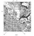
- FIG. 7is a screen capture illustrating a presentation 700 having detail-in-context lenses 710 , 711 and associated GUIs 701 , 702 for selecting points between which to measure in an original digital image or representation in accordance with an embodiment of the invention.
- a userTo make a measurement between two points in an original digital image, a user first adds detail-in-context lenses 710 , 711 to the original image to create a detail-in-context presentation 700 .
- the lens 710 , 711enable the user to view high resolution data in the focus of each lens.
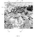
- FIG. 8is a screen capture illustrating a presentation 800 having two detail-in-context lenses 710 , 711 , associated GUIs 701 , 702 , and a measuring tool GUI 810 , 820 for displaying the measurement between selected points 750 , 760 in an original digital image or representation in accordance with an embodiment of the invention.
- the usermay select a measuring tool to determine the distance between the points 750 , 760 .
- the measuring toolmay be selected using a pull-down menu selection, tool bar, etc.
- the measuring toolmay present a measuring tool GUI which may include a measured value icon 820 for displaying the measured value or distance between the selected points 750 , 760 and a line segment icon 810 for displaying the measurement path between the selected points 750 , 760 to a user.
- a measured value icon 820for displaying the measured value or distance between the selected points 750 , 760
- a line segment icon 810for displaying the measurement path between the selected points 750 , 760 to a user.
- the selected points 750 , 760are contained within the focal region of each lens 710 , 711 which may be displayed at a higher resolution that the surrounding presentation 800 , the measured value may be determined more accurately.
- the distance between Terrace and Victoriahas a measure value 820 of 734, 771 meters.
- two lenses 710 , 711are added to the presentation 700 , 800 before the measuring tool GUI 810 , 820 is activated.
- the lenses 710 , 711 and measuring tool GUI 810 , 820can be combined. That is, the user may first add a lens 710 to a presentation 800 or the user may move a pre-existing lens into place at, say, the Terrace point 750 in FIG. 8 . At this stage, before the Victoria point 760 is selected, the measuring tool GUI 810 , 820 is activated. Now, to select the second point 763 , the end point 830 of the line segment icon 810 (i.e. the point over the cursor's position) is moved (e.g.
- the second lens 711is presented over and moves with the end point 830 .
- Thisfacilitates the accurate selection of the second point 760 for defining the distance to be measured (i.e. the line segment between points 750 , 760 ).
- a new lensmay be added to the presentation.
- Cropping with a Single Detail-In-Context LensAbove methods for cropping and measuring an original image are described in which multiple lenses are used. In the following, embodiments for cropping and measuring using a single lens are described.
- the lensmay be a carrier for the cropping or measurement tool, or the lens may be the tool itself. In both the single lens and multiple lenses embodiments, accuracy of cropping and measurement is improved.
- FIG. 9is a screen capture illustrating a presentation 900 having a single detail-in-context lens 910 and associated GUI 901 for defining the corners of a bounding rectangle GUI for cropping an original digital image or representation in accordance with an embodiment of the invention.
- a scale icon 940may be included in the presentation 900 .
- the userfirst selects the cropping tool (which is associated with a lens 910 ) using a pull-down menu selection, tool bar, etc., and then selects a starting or first point 920 using a point and click operation. This places a lens 910 and an associated GUI 901 over the first point 920 .
- FIG. 10is a screen capture illustrating a presentation 1000 having a single detail-in-context lens 910 , an associated GUI 901 , and a bounding rectangle GUI or icon 1010 for cropping an original digital image or representation to produce a cropped image 1040 in accordance with an embodiment of the invention.
- the bounding rectangle GUI 1010may be dynamically presented as the lens 910 is dragged diagonally from the first point 920 to the second point 930 .
- the bounding rectangle GUI 1010defines the area of the cropped image 1040 .
- the bounding rectangle GUI 1010may be drawn by first activating the tool (e.g. tool bar, etc.), followed by a point and click operation to locate the first point or corner 920 , while maintaining a depressed mouse selection button, a drag operation during which the lens 910 is presented over the end of the crop line 950 (i.e. over the cursor's position, that is, the end of the crop line 950 is attached to the lens 910 which moves with the crop line end 950 as it is repositioned by a user), and a mouse selection button release to select the second point or corner 930 .
- the bounding rectangle GUI 1010is dynamically presented as the end of the crop line 950 is moved by the user.
- the bounding rectangle GUI 1010may have a shape other than rectangular.
- a polygonal shaped bounding GUImay be defined with three or more lens.
- the outline of the bounding GUImay pass through each lens.
- the polygonal shaped bounding GUImay be drawn, say, through an activation step, followed by a point and click to locate the first point, a series of click and drag operations to chose each subsequent point of the polygon, and ending with a double click operation that leaves a lens placed over the last selected point or corner.
- a lensmay be presented over the end of the crop line (i.e. over the cursor's position). In other words, the end of the crop line is attached to a lens that moves with the crop line end as it is repositioned by a user.
- an alternate cursor iconmay be displayed over the presentation 900 , 1000 to replace the cursor 401 or may be displayed in combination with the cursor 401 .
- the alternate cursor iconmay be a lens 910 , a cropping cursor icon (not shown), or a combination lens 910 and cropping cursor icon.
- FIG. 11Ais a screen capture illustrating a presentation 1100 having a single detail-in-context lens 1110 and an associated GUI 1101 for selecting points between which to measure in an original digital image or representation in accordance with an embodiment of the invention.
- FIG. 11Bis a screen capture illustrating a presentation 1100 having a single detail-in-context lens 1110 , an associated GUI 1101 , and a measuring tool GUI 1140 , 1141 , for displaying the measurement between selected points 1120 , 1130 in an original digital image or representation in accordance with an embodiment of the invention.
- FIG. 11Ais a screen capture illustrating a presentation 1100 having a single detail-in-context lens 1110 and an associated GUI 1101 for selecting points between which to measure in an original digital image or representation in accordance with an embodiment of the invention.
- FIG. 11Bis a screen capture illustrating a presentation 1100 having a single detail-in-context lens 1110 , an associated GUI 1101 , and a measuring tool GUI 1140
- 11Cis a screen capture illustrating a presentation 1100 having a single detail-in-context lens 1110 , an associated GUI 1101 , and a measuring tool GUI 1140 , 1142 , 1142 , 1143 for displaying the measurement between selected points 1120 , 1130 , 1160 in an original digital image or representation in accordance with an embodiment of the invention.
- the userTo make a measurement in the original image 1100 , the user first selects the measuring tool (which is associated with a lens 1110 ) using a pull-down menu selection, tool bar, etc., and then selects a starting or first point 1120 using a point and click operation. This places a lens 1110 and an associated GUI 1101 over the first point 1120 as shown in FIG. 11A .
- a measuring tool icon 1180may also be displayed over the first point 1120 as mentioned above.
- the lens 1110enables the user to view high resolution data in its focus.
- the userdrags the lens 1110 to select a second point 1130 for the measurement as shown in FIG. 11B .
- the measuring toolmay present a measuring tool GUI which may include a measured value icon 1141 for displaying the measured value or distance between the selected points 1120 , 1130 and a line segment icon 1140 for displaying the measurement path between the selected points 1120 , 1130 as shown in FIG. 11B .
- the measuring tool GUI 1140 , 1141may be dynamically presented as the lens 1110 is dragged from the first point 1120 to the second point 1130 .
- a usermay make linked measurements in one or more operations.
- Linked line segment icons 1140 , 1142may be drawn, say, through an activation step, followed by a point and click to locate the first point 1120 , a series of click and drag operations to chose each subsequent point 1130 , 1160 of the linked line segment, and ending with a double click operation that leaves a lens 1110 placed over the last selected point 1160 .
- a lens 1110may be presented over the end of the line segment 1150 (i.e. over the cursor's position). In other words, the end of the line segment 1150 is attached to a lens 1110 that moves with the end of the line segment 1150 as it is repositioned by a user.
- a scale icon 1170may be included in the presentation 1100 .
- an alternate cursor iconmay be displayed over the presentation 1100 to replace the cursor 401 or may be displayed in combination with the cursor 401 .
- the alternate cursor iconmay be a lens 1110 , a measuring cursor icon 1180 , or a combination lens 1110 and measuring cursor icon 1180 .
- the line segment icon 1140may be presented as an exclusive OR (XOR) with the underlying portion of the original or background image 1100 .
- FIG. 12is a flow chart 1200 illustrating a method for cropping a computer generated original image on a display 340 in accordance with an embodiment of the invention. At step 1201 , the method starts.
- a user-selected movable boundary 610 , 1010 on the original imageis adjusted to define a cropped image 640 , 1040 within the boundary, the boundary being defined by two or more points 620 , 630 , 920 , 930 on the original image.
- a lens surface 510 , 511 , 910is created for one or more of the regions surrounding the points 620 , 630 , 920 , 930 .
- a GUI 501 , 502 , 901is displayed over one or more of the regions for adjusting the lens surface 510 , 511 , 910 .
- the original imageis transformed by applying a distortion function defining the lens surface to the original image.
- the original imageis distorted 500 , 600 , 900 , 1000 in regions surrounding the points, whereby the boundary 610 , 1010 is accurately positioned for cropping.
- step 1207the method ends.
- FIG. 13is a flow chart 1300 illustrating a method for measuring within a computer generated original image on a display 340 in accordance with an embodiment of the invention. At step 1301 , the method starts.
- a user-selected movable line segment 810 , 1140 , 1142 on the original imageis adjusted to define points 750 , 760 , 1120 , 1130 , 1160 on the original image for measuring between.
- a lens surface 710 , 711 , 1110is created for one or more of the regions surrounding the points 750 , 760 , 1120 , 1130 , 1160 .
- a GUI 701 , 702 , 1101is displayed over one or more of the regions for adjusting the lens surface 710 , 711 , 1110 .
- the original imageis transformed by applying a distortion function defining the lens surface to the original image.
- the original imageis distorted 700 , 800 , 1100 in regions surrounding the points, whereby the points 750 , 760 , 1120 , 1130 , 1160 are accurately positioned for measuring.
- step 1307the method ends.
- Data Carrier ProductThe sequences of instructions which when executed cause the method described herein to be performed by the exemplary data processing system of FIG. 3 can be contained in a data carrier product according to one embodiment of the invention. This data carrier product can be loaded into and run by the exemplary data processing system of FIG. 3 .
- Computer Software ProductThe sequences of instructions which when executed cause the method described herein to be performed by the exemplary data processing system of FIG. 3 can be contained in a computer software product according to one embodiment of the invention. This computer software product can be loaded into and run by the exemplary data processing system of FIG. 3 .
- Integrated Circuit ProductThe sequences of instructions which when executed cause the method described herein to be performed by the exemplary data processing system of FIG. 3 can be contained in an integrated circuit product including a coprocessor or memory according to one embodiment of the invention. This integrated circuit product can be installed in the exemplary data processing system of FIG. 3 .
Landscapes
- Engineering & Computer Science (AREA)
- Theoretical Computer Science (AREA)
- General Engineering & Computer Science (AREA)
- Physics & Mathematics (AREA)
- General Physics & Mathematics (AREA)
- Human Computer Interaction (AREA)
- Computer Hardware Design (AREA)
- User Interface Of Digital Computer (AREA)
- Image Processing (AREA)
Abstract
Description
Claims (21)
Priority Applications (5)
| Application Number | Priority Date | Filing Date | Title |
|---|---|---|---|
| US11/443,124US7489321B2 (en) | 2002-07-16 | 2006-05-31 | Using detail-in-context lenses for accurate digital image cropping and measurement |
| US12/368,263US7978210B2 (en) | 2002-07-16 | 2009-02-09 | Detail-in-context lenses for digital image cropping and measurement |
| US12/368,268US9760235B2 (en) | 2001-06-12 | 2009-02-09 | Lens-defined adjustment of displays |
| US12/368,267US8120624B2 (en) | 2002-07-16 | 2009-02-09 | Detail-in-context lenses for digital image cropping, measurement and online maps |
| US13/358,147US9804728B2 (en) | 2002-07-16 | 2012-01-25 | Detail-in-context lenses for digital image cropping, measurement and online maps |
Applications Claiming Priority (4)
| Application Number | Priority Date | Filing Date | Title |
|---|---|---|---|
| CA2,393,708 | 2002-07-16 | ||
| CA 2393708CA2393708A1 (en) | 2002-07-16 | 2002-07-16 | Applications of multiple lenses in detail-in-context data presentations |
| CA 2394119CA2394119A1 (en) | 2002-07-18 | 2002-07-18 | Cropping and measuring with a single lens |
| CA2,394,119 | 2002-07-18 |
Related Parent Applications (2)
| Application Number | Title | Priority Date | Filing Date |
|---|---|---|---|
| US11/473,152Continuation-In-PartUS20070064018A1 (en) | 2002-07-16 | 2006-06-23 | Detail-in-context lenses for online maps |
| US11/691,686Continuation-In-PartUS9323413B2 (en) | 2001-06-12 | 2007-03-27 | Graphical user interface with zoom for detail-in-context presentations |
Related Child Applications (1)
| Application Number | Title | Priority Date | Filing Date |
|---|---|---|---|
| US11/443,124ContinuationUS7489321B2 (en) | 2001-06-12 | 2006-05-31 | Using detail-in-context lenses for accurate digital image cropping and measurement |
Publications (2)
| Publication Number | Publication Date |
|---|---|
| US20040056869A1 US20040056869A1 (en) | 2004-03-25 |
| US7084886B2true US7084886B2 (en) | 2006-08-01 |
Family
ID=31994850
Family Applications (3)
| Application Number | Title | Priority Date | Filing Date |
|---|---|---|---|
| US10/614,754Expired - LifetimeUS7084886B2 (en) | 2001-06-12 | 2003-07-08 | Using detail-in-context lenses for accurate digital image cropping and measurement |
| US11/443,124Expired - LifetimeUS7489321B2 (en) | 2001-06-12 | 2006-05-31 | Using detail-in-context lenses for accurate digital image cropping and measurement |
| US12/368,263Expired - Fee RelatedUS7978210B2 (en) | 2002-07-16 | 2009-02-09 | Detail-in-context lenses for digital image cropping and measurement |
Family Applications After (2)
| Application Number | Title | Priority Date | Filing Date |
|---|---|---|---|
| US11/443,124Expired - LifetimeUS7489321B2 (en) | 2001-06-12 | 2006-05-31 | Using detail-in-context lenses for accurate digital image cropping and measurement |
| US12/368,263Expired - Fee RelatedUS7978210B2 (en) | 2002-07-16 | 2009-02-09 | Detail-in-context lenses for digital image cropping and measurement |
Country Status (1)
| Country | Link |
|---|---|
| US (3) | US7084886B2 (en) |
Cited By (28)
| Publication number | Priority date | Publication date | Assignee | Title |
|---|---|---|---|---|
| US20040025112A1 (en)* | 2002-08-01 | 2004-02-05 | Chasen Jeffrey Martin | Method and apparatus for resizing video content displayed within a graphical user interface |
| US20050036708A1 (en)* | 2003-08-11 | 2005-02-17 | David Boll | Systems and methods for cropping captured images |
| US20050162447A1 (en)* | 2004-01-28 | 2005-07-28 | Tigges Mark H.A. | Dynamic width adjustment for detail-in-context lenses |
| US20070064018A1 (en)* | 2005-06-24 | 2007-03-22 | Idelix Software Inc. | Detail-in-context lenses for online maps |
| US20090147023A1 (en)* | 2002-07-16 | 2009-06-11 | Noregin Assets N.V., L.L.C. | Detail-in-context lenses for digital image cropping and measurement |
| US7580036B2 (en) | 2005-04-13 | 2009-08-25 | Catherine Montagnese | Detail-in-context terrain displacement algorithm with optimizations |
| US7667699B2 (en) | 2002-02-05 | 2010-02-23 | Robert Komar | Fast rendering of pyramid lens distorted raster images |
| US7714859B2 (en) | 2004-09-03 | 2010-05-11 | Shoemaker Garth B D | Occlusion reduction and magnification for multidimensional data presentations |
| US7737976B2 (en) | 2001-11-07 | 2010-06-15 | Maria Lantin | Method and system for displaying stereoscopic detail-in-context presentations |
| US7761713B2 (en) | 2002-11-15 | 2010-07-20 | Baar David J P | Method and system for controlling access in detail-in-context presentations |
| US7773101B2 (en) | 2004-04-14 | 2010-08-10 | Shoemaker Garth B D | Fisheye lens graphical user interfaces |
| US20100283800A1 (en)* | 2009-05-08 | 2010-11-11 | International Business Machines Corporation | Magnifying content on a graphical display |
| US20100325538A1 (en)* | 2007-05-01 | 2010-12-23 | Michael Joseph Dattilo | Method and Apparatus to Digitally Whiteout Mistakes on a Printed Form |
| US7966570B2 (en) | 2001-05-03 | 2011-06-21 | Noregin Assets N.V., L.L.C. | Graphical user interface for detail-in-context presentations |
| US7983473B2 (en) | 2006-04-11 | 2011-07-19 | Noregin Assets, N.V., L.L.C. | Transparency adjustment of a presentation |
| US7995078B2 (en) | 2004-09-29 | 2011-08-09 | Noregin Assets, N.V., L.L.C. | Compound lenses for multi-source data presentation |
| US8031206B2 (en) | 2005-10-12 | 2011-10-04 | Noregin Assets N.V., L.L.C. | Method and system for generating pyramid fisheye lens detail-in-context presentations |
| US8106927B2 (en) | 2004-05-28 | 2012-01-31 | Noregin Assets N.V., L.L.C. | Graphical user interfaces and occlusion prevention for fisheye lenses with line segment foci |
| US8120624B2 (en) | 2002-07-16 | 2012-02-21 | Noregin Assets N.V. L.L.C. | Detail-in-context lenses for digital image cropping, measurement and online maps |
| US8139089B2 (en) | 2003-11-17 | 2012-03-20 | Noregin Assets, N.V., L.L.C. | Navigating digital images using detail-in-context lenses |
| US8225225B2 (en) | 2002-07-17 | 2012-07-17 | Noregin Assets, N.V., L.L.C. | Graphical user interface having an attached toolbar for drag and drop editing in detail-in-context lens presentations |
| USRE43742E1 (en) | 2000-12-19 | 2012-10-16 | Noregin Assets N.V., L.L.C. | Method and system for enhanced detail-in-context viewing |
| US8311915B2 (en) | 2002-09-30 | 2012-11-13 | Noregin Assets, N.V., LLC | Detail-in-context lenses for interacting with objects in digital image presentations |
| US8416266B2 (en) | 2001-05-03 | 2013-04-09 | Noregin Assetts N.V., L.L.C. | Interacting with detail-in-context presentations |
| US9026938B2 (en) | 2007-07-26 | 2015-05-05 | Noregin Assets N.V., L.L.C. | Dynamic detail-in-context user interface for application access and content access on electronic displays |
| US9317945B2 (en) | 2004-06-23 | 2016-04-19 | Callahan Cellular L.L.C. | Detail-in-context lenses for navigation |
| US9323413B2 (en) | 2001-06-12 | 2016-04-26 | Callahan Cellular L.L.C. | Graphical user interface with zoom for detail-in-context presentations |
| US9760235B2 (en) | 2001-06-12 | 2017-09-12 | Callahan Cellular L.L.C. | Lens-defined adjustment of displays |
Families Citing this family (22)
| Publication number | Priority date | Publication date | Assignee | Title |
|---|---|---|---|---|
| US20060082901A1 (en)* | 2004-10-14 | 2006-04-20 | Idelix Software Inc. | Interacting with detail-in-context presentations |
| JP3488874B2 (en)* | 2001-10-31 | 2004-01-19 | シャープ株式会社 | Editing apparatus, editing method, editing program, and computer-readable recording medium recording editing program |
| US20070097109A1 (en)* | 2005-10-18 | 2007-05-03 | Idelix Software Inc. | Method and system for generating detail-in-context presentations in client/server systems |
| CA2407383A1 (en)* | 2002-10-10 | 2004-04-10 | Idelix Software Inc. | Editing multiple layers of a presentation using detail-in-context lenses |
| US7705858B2 (en)* | 2004-10-06 | 2010-04-27 | Apple Inc. | Techniques for displaying digital images on a display |
| US7804508B2 (en)* | 2004-10-06 | 2010-09-28 | Apple Inc. | Viewing digital images on a display using a virtual loupe |
| US8456488B2 (en)* | 2004-10-06 | 2013-06-04 | Apple Inc. | Displaying digital images using groups, stacks, and version sets |
| US20060222263A1 (en)* | 2005-04-04 | 2006-10-05 | Carlson Eric A | Linear measurement machine-readable medium, method and system |
| US8250486B2 (en)* | 2006-01-19 | 2012-08-21 | International Business Machines Corporation | Computer controlled user interactive display interface for accessing graphic tools with a minimum of display pointer movement |
| US7889212B2 (en)* | 2006-09-07 | 2011-02-15 | Apple Inc. | Magnifying visual information using a center-based loupe |
| US20090037840A1 (en)* | 2007-08-03 | 2009-02-05 | Siemens Medical Solutions Usa, Inc. | Location Determination For Z-Direction Increments While Viewing Medical Images |
| US8775953B2 (en) | 2007-12-05 | 2014-07-08 | Apple Inc. | Collage display of image projects |
| KR101315415B1 (en)* | 2007-12-06 | 2013-10-07 | 삼성전자주식회사 | Image processing apparatus and control method thereof |
| US20100153168A1 (en)* | 2008-12-15 | 2010-06-17 | Jeffrey York | System and method for carrying out an inspection or maintenance operation with compliance tracking using a handheld device |
| USD679709S1 (en)* | 2011-04-06 | 2013-04-09 | Inmusic Brands, Inc. | Book scanning device camera assembly and page compressor |
| US20120278754A1 (en)* | 2011-04-29 | 2012-11-01 | Google Inc. | Elastic Over-Scroll |
| US20150135125A1 (en)* | 2013-11-12 | 2015-05-14 | Apple Inc. | Bubble loupes |
| EP3085082B1 (en)* | 2013-12-17 | 2020-04-29 | Marsupial Holdings Inc. | Integrated microoptic imager, processor, and display |
| KR20150105140A (en)* | 2014-03-07 | 2015-09-16 | 삼성전자주식회사 | Mobile device capable of enlarging content displayed thereon and method therefor |
| US9888167B2 (en)* | 2014-05-30 | 2018-02-06 | General Electric Company | Selectable enhancement window for incremental measurement adjustment |
| JP6711081B2 (en)* | 2016-03-31 | 2020-06-17 | ブラザー工業株式会社 | Image processing program and information processing apparatus |
| US20200045375A1 (en)* | 2018-07-31 | 2020-02-06 | Salesforce.Com, Inc. | Video playback in a web-application using a resizable and repositionable window |
Citations (16)
| Publication number | Priority date | Publication date | Assignee | Title |
|---|---|---|---|---|
| US5227771A (en) | 1991-07-10 | 1993-07-13 | International Business Machines Corporation | Method and system for incrementally changing window size on a display |
| US5473740A (en) | 1993-12-29 | 1995-12-05 | International Business Machines Corporation | Method and apparatus for interactively indicating image boundaries in digital image cropping |
| US5798752A (en)* | 1993-07-21 | 1998-08-25 | Xerox Corporation | User interface having simultaneously movable tools and cursor |
| US6133914A (en)* | 1998-01-07 | 2000-10-17 | Rogers; David W. | Interactive graphical user interface |
| US6201548B1 (en) | 1998-02-24 | 2001-03-13 | Hewlett-Packard Company | Graphical user interface for image editing |
| US6201546B1 (en)* | 1998-05-29 | 2001-03-13 | Point Cloud, Inc. | Systems and methods for generating three dimensional, textured models |
| US6215491B1 (en) | 1992-12-14 | 2001-04-10 | Monkeymedia, Inc. | Computer user interface with non-salience deemphasis |
| US6304271B1 (en) | 1999-02-05 | 2001-10-16 | Sony Corporation | Apparatus and method for cropping an image in a zooming graphical user interface |
| US20010048447A1 (en)* | 2000-06-05 | 2001-12-06 | Fuji Photo Film Co., Ltd. | Image croppin and synthesizing method, and imaging apparatus |
| US20020044154A1 (en) | 2000-10-18 | 2002-04-18 | Baar David J. P. | Elastic presentation space |
| US6396962B1 (en) | 1999-01-29 | 2002-05-28 | Sony Corporation | System and method for providing zooming video |
| US6411274B2 (en) | 1997-06-02 | 2002-06-25 | Sony Corporation | Digital map display zooming method, digital map display zooming device, and storage medium for storing digital map display zooming program |
| US6417867B1 (en) | 1999-05-27 | 2002-07-09 | Sharp Laboratories Of America, Inc. | Image downscaling using peripheral vision area localization |
| US6487497B2 (en) | 1998-03-25 | 2002-11-26 | Navigation Technologies Corporation | Method and system for route calculation in a navigation application |
| US6504535B1 (en)* | 1998-06-30 | 2003-01-07 | Lucent Technologies Inc. | Display techniques for three-dimensional virtual reality |
| US6552737B1 (en) | 1999-02-18 | 2003-04-22 | Fujitsu Limited | Control of window size in response to user operation |
Family Cites Families (251)
| Publication number | Priority date | Publication date | Assignee | Title |
|---|---|---|---|---|
| US3201546A (en)* | 1961-07-24 | 1965-08-17 | Hart Mfg Canada Ltd | Power controlling device for electrical heating elements |
| US3704938A (en)* | 1970-10-01 | 1972-12-05 | Hyman Fanselow | Punch card viewer |
| US3762799A (en)* | 1971-08-27 | 1973-10-02 | J Shapiro | Magnifying indicator for a burette |
| US3739739A (en)* | 1972-08-24 | 1973-06-19 | R Brase | Instrument for isolating rows of printed matter for reading |
| EP0112414B1 (en) | 1982-12-22 | 1987-09-09 | International Business Machines Corporation | Image transformations on an interactive raster scan or matrix display |
| US4581647A (en) | 1983-09-19 | 1986-04-08 | Vye Richard A | Computerized automatic focusing control system for multiple television cameras |
| US4630110A (en) | 1984-02-15 | 1986-12-16 | Supervision Control Systems, Inc. | Surveillance system |
| US4791581A (en) | 1985-07-27 | 1988-12-13 | Sony Corporation | Method and apparatus of forming curved surfaces |
| GB8611554D0 (en) | 1986-05-12 | 1986-06-18 | Crosfield Electronics Ltd | Image display |
| US4888713B1 (en) | 1986-09-05 | 1993-10-12 | Cdi Technologies, Inc. | Surface detail mapping system |
| US4790028A (en) | 1986-09-12 | 1988-12-06 | Westinghouse Electric Corp. | Method and apparatus for generating variably scaled displays |
| US4985849A (en) | 1987-06-12 | 1991-01-15 | Canon Kabushiki Kaisha | Image processing system for forming a slantwise-mapped or rotated modified image of an original image |
| GB8722540D0 (en)* | 1987-09-24 | 1987-10-28 | Unilever Plc | Composition for softening fabrics |
| US4757616A (en)* | 1987-10-26 | 1988-07-19 | Educational Insights | Ruler with magnifying cursor |
| US5185599A (en) | 1987-10-26 | 1993-02-09 | Tektronix, Inc. | Local display bus architecture and communications method for Raster display |
| US5048077A (en) | 1988-07-25 | 1991-09-10 | Reflection Technology, Inc. | Telephone handset with full-page visual display |
| US4992866A (en) | 1989-06-29 | 1991-02-12 | Morgan Jack B | Camera selection and positioning system and method |
| US5175808A (en) | 1989-09-12 | 1992-12-29 | Pixar | Method and apparatus for non-affine image warping |
| US5206721A (en) | 1990-03-08 | 1993-04-27 | Fujitsu Limited | Television conference system |
| US5031918A (en)* | 1990-04-24 | 1991-07-16 | Fred Silber Compamy | Magnifying marker for a game board |
| DE4023318A1 (en) | 1990-07-21 | 1992-02-20 | Fraunhofer Ges Forschung | METHOD FOR PERFORMING A VARIABLE DIALOG WITH TECHNICAL DEVICES |
| US5269687A (en)* | 1990-08-01 | 1993-12-14 | Atari Games Corporation | System and method for recursive driver training |
| US5250934A (en) | 1990-12-31 | 1993-10-05 | Xerox Corporation | Method and apparatus for thinning printed images |
| US5258837A (en) | 1991-01-07 | 1993-11-02 | Zandar Research Limited | Multiple security video display |
| US5200818A (en) | 1991-03-22 | 1993-04-06 | Inbal Neta | Video imaging system with interactive windowing capability |
| US5416900A (en) | 1991-04-25 | 1995-05-16 | Lotus Development Corporation | Presentation manager |
| US5341466A (en) | 1991-05-09 | 1994-08-23 | New York University | Fractal computer user centerface with zooming capability |
| US5185667A (en) | 1991-05-13 | 1993-02-09 | Telerobotics International, Inc. | Omniview motionless camera orientation system |
| US5375199A (en) | 1991-06-04 | 1994-12-20 | Digital Equipment Corporation | System monitoring method and device including a graphical user interface to view and manipulate system information |
| ITMI911761A1 (en)* | 1991-06-26 | 1992-12-27 | Ctp Spa | FUNCTIONAL RING |
| CA2077173C (en) | 1991-11-22 | 2003-04-22 | Michael Chen | Method and apparatus for direct manipulation of 3-d objects on computer displays |
| US5321807A (en) | 1991-11-27 | 1994-06-14 | Mumford Christopher J | Accelerated graphics display method |
| US5610653A (en) | 1992-02-07 | 1997-03-11 | Abecassis; Max | Method and system for automatically tracking a zoomed video image |
| JPH05334427A (en) | 1992-06-03 | 1993-12-17 | Hitachi Ltd | Image scaling method |
| US5594859A (en) | 1992-06-03 | 1997-01-14 | Digital Equipment Corporation | Graphical user interface for video teleconferencing |
| US5329310A (en) | 1992-06-30 | 1994-07-12 | The Walt Disney Company | Method and apparatus for controlling distortion of a projected image |
| US5309279A (en)* | 1992-08-21 | 1994-05-03 | Halstead Madeline C | Script view a curved convex magnifying device |
| US5751289A (en) | 1992-10-01 | 1998-05-12 | University Corporation For Atmospheric Research | Virtual reality imaging system with image replay |
| US5432895A (en) | 1992-10-01 | 1995-07-11 | University Corporation For Atmospheric Research | Virtual reality imaging system |
| JP3256293B2 (en) | 1992-10-19 | 2002-02-12 | 富士写真光機株式会社 | Head control device for TV camera |
| US5369527A (en) | 1992-12-03 | 1994-11-29 | Mccracken; Robert | Melanoma detection device |
| EP0605945B1 (en)* | 1992-12-15 | 1997-12-29 | Sun Microsystems, Inc. | Method and apparatus for presenting information in a display system using transparent windows |
| DE69418908T2 (en) | 1993-01-26 | 2000-01-20 | Sun Microsystems Inc | Method and device for viewing information in a computer database |
| US5652851A (en) | 1993-07-21 | 1997-07-29 | Xerox Corporation | User interface technique for producing a second image in the spatial context of a first image using a model-based operation |
| US5818455A (en) | 1993-07-21 | 1998-10-06 | Xerox Corporation | Method and apparatus for operating on the model data structure of an image to produce human perceptible output using a viewing operation region having explicit multiple regions |
| US5596690A (en) | 1993-07-21 | 1997-01-21 | Xerox Corporation | Method and apparatus for operating on an object-based model data structure to produce a second image in the spatial context of a first image |
| US5581670A (en) | 1993-07-21 | 1996-12-03 | Xerox Corporation | User interface having movable sheet with click-through tools |
| JP2916076B2 (en) | 1993-08-26 | 1999-07-05 | シャープ株式会社 | Image display device |
| CN1135823A (en) | 1993-10-20 | 1996-11-13 | 电视会议系统公司 | Adaptive videoconferencing system |
| US5583977A (en) | 1993-10-21 | 1996-12-10 | Taligent, Inc. | Object-oriented curve manipulation system |
| US5670984A (en)* | 1993-10-26 | 1997-09-23 | Xerox Corporation | Image lens |
| JP3697276B2 (en) | 1993-10-27 | 2005-09-21 | ゼロックス コーポレイション | Image display method, image display apparatus, and image scaling method |
| TW371334B (en) | 1994-03-18 | 1999-10-01 | Hitachi Ltd | Method for retrieving database with image information |
| US5451998A (en) | 1994-04-04 | 1995-09-19 | Hamrick; Daniel C. | Home shopping video catalog |
| US5564004A (en) | 1994-04-13 | 1996-10-08 | International Business Machines Corporation | Method and system for facilitating the selection of icons |
| US5689628A (en) | 1994-04-14 | 1997-11-18 | Xerox Corporation | Coupling a display object to a viewpoint in a navigable workspace |
| WO1995029465A1 (en) | 1994-04-21 | 1995-11-02 | Sandia Corporation | Multi-dimensional user oriented synthetic environment |
| USRE44685E1 (en) | 1994-04-28 | 2013-12-31 | Opentv, Inc. | Apparatus for transmitting and receiving executable applications as for a multimedia system, and method and system to order an item using a distributed computing system |
| US5796426A (en) | 1994-05-27 | 1998-08-18 | Warp, Ltd. | Wide-angle image dewarping method and apparatus |
| US5521634A (en) | 1994-06-17 | 1996-05-28 | Harris Corporation | Automatic detection and prioritized image transmission system and method |
| WO1996003839A1 (en) | 1994-07-26 | 1996-02-08 | Maxpro Systems Pty. Ltd. | A video security system |
| JP2679637B2 (en)* | 1994-08-30 | 1997-11-19 | 日本電気株式会社 | Image display device |
| US5613032A (en) | 1994-09-02 | 1997-03-18 | Bell Communications Research, Inc. | System and method for recording, playing back and searching multimedia events wherein video, audio and text can be searched and retrieved |
| EP0713331B1 (en) | 1994-11-17 | 2001-03-14 | Canon Kabushiki Kaisha | Camera control device and method |
| US5644758A (en) | 1994-12-13 | 1997-07-01 | Microsoft Corporation | Bitmap block transfer image conversion |
| US6204845B1 (en) | 1994-12-16 | 2001-03-20 | International Business Machines Corporation | Ergonomic viewable object processor |
| JP3265893B2 (en) | 1995-02-13 | 2002-03-18 | 株式会社日立製作所 | Image display device |
| JPH08223561A (en) | 1995-02-17 | 1996-08-30 | Nippon Denki Syst Kensetsu Kk | Method and device for controlling camera by the use of monitor area diagram |
| US5657246A (en) | 1995-03-07 | 1997-08-12 | Vtel Corporation | Method and apparatus for a video conference user interface |
| US5729673A (en) | 1995-04-07 | 1998-03-17 | Avid Technology, Inc. | Direct manipulation of two-dimensional moving picture streams in three-dimensional space |
| JP3890621B2 (en) | 1995-04-21 | 2007-03-07 | ソニー株式会社 | Image display apparatus and method |
| US5721853A (en) | 1995-04-28 | 1998-02-24 | Ast Research, Inc. | Spot graphic display element with open locking and periodic animation |
| US5973694A (en) | 1995-06-02 | 1999-10-26 | Chatham Telecommunications, Inc., | Method of communication using sized icons, text, and audio |
| US5926209A (en) | 1995-07-14 | 1999-07-20 | Sensormatic Electronics Corporation | Video camera apparatus with compression system responsive to video camera adjustment |
| US6037939A (en) | 1995-09-27 | 2000-03-14 | Sharp Kabushiki Kaisha | Method for enabling interactive manipulation of data retained in computer system, and a computer system for implementing the method |
| US6081277A (en) | 1995-09-28 | 2000-06-27 | Sony Corporation | Apparatus and method for controlling image display |
| JP3176541B2 (en) | 1995-10-16 | 2001-06-18 | シャープ株式会社 | Information retrieval device and information retrieval method |
| US5786814A (en) | 1995-11-03 | 1998-07-28 | Xerox Corporation | Computer controlled display system activities using correlated graphical and timeline interfaces for controlling replay of temporal data representing collaborative activities |
| JPH09123848A (en) | 1995-11-06 | 1997-05-13 | Toyota Motor Corp | Information display device for vehicles |
| US5959605A (en) | 1995-11-22 | 1999-09-28 | Picker International, Inc. | Video magnifier |
| US6463930B2 (en)* | 1995-12-08 | 2002-10-15 | James W. Biondi | System for automatically weaning a patient from a ventilator, and method thereof |
| US6266082B1 (en) | 1995-12-19 | 2001-07-24 | Canon Kabushiki Kaisha | Communication apparatus image processing apparatus communication method and image processing method |
| US5848231A (en) | 1996-02-12 | 1998-12-08 | Teitelbaum; Neil | System configuration contingent upon secure input |
| US6067372A (en) | 1996-02-22 | 2000-05-23 | University Of Pittsburgh | Method and system to enhance robust identification of abnormal regions in radiographs |
| JPH09289606A (en) | 1996-04-23 | 1997-11-04 | Canon Inc | Image display device and camera control device |
| JP3798469B2 (en) | 1996-04-26 | 2006-07-19 | パイオニア株式会社 | Navigation device |
| US5742272A (en) | 1996-04-29 | 1998-04-21 | Ati Technologies Inc. | Accelerated full screen video playback |
| US5754348A (en)* | 1996-05-14 | 1998-05-19 | Planetweb, Inc. | Method for context-preserving magnification of digital image regions |
| US5731805A (en) | 1996-06-25 | 1998-03-24 | Sun Microsystems, Inc. | Method and apparatus for eyetrack-driven text enlargement |
| US6198484B1 (en) | 1996-06-27 | 2001-03-06 | Kabushiki Kaisha Toshiba | Stereoscopic display system |
| TW348239B (en) | 1996-06-28 | 1998-12-21 | Cirrus Logic Inc | Embedding a transparency enable bit as part of a resizing bit block transfer operation |
| US6108005A (en) | 1996-08-30 | 2000-08-22 | Space Corporation | Method for producing a synthesized stereoscopic image |
| US6139434A (en) | 1996-09-24 | 2000-10-31 | Nintendo Co., Ltd. | Three-dimensional image processing apparatus with enhanced automatic and user point of view control |
| JPH10105362A (en) | 1996-09-30 | 1998-04-24 | Toshiba Corp | Portable information device and enlarged display control method |
| US5950216A (en) | 1996-11-12 | 1999-09-07 | International Business Machines Corporation | Method and system for marking and subsequently retrieving a collection of objects within a multipage compound document utilizing selectable page numbered dialog boxes |
| US6256115B1 (en) | 1997-02-21 | 2001-07-03 | Worldquest Network, Inc. | Facsimile network |
| US5915379A (en)* | 1997-03-14 | 1999-06-29 | Nellcor Puritan Bennett Incorporated | Graphic user interface for a patient ventilator |
| US5991877A (en) | 1997-04-03 | 1999-11-23 | Lockheed Martin Corporation | Object-oriented trusted application framework |
| US6026376A (en) | 1997-04-15 | 2000-02-15 | Kenney; John A. | Interactive electronic shopping system and method |
| US6057844A (en) | 1997-04-28 | 2000-05-02 | Adobe Systems Incorporated | Drag operation gesture controller |
| US6073036A (en) | 1997-04-28 | 2000-06-06 | Nokia Mobile Phones Limited | Mobile station with touch input having automatic symbol magnification function |
| US5949430A (en) | 1997-05-20 | 1999-09-07 | Microsoft Corporation | Peripheral lenses for simulating peripheral vision on a display device |
| US6204850B1 (en) | 1997-05-30 | 2001-03-20 | Daniel R. Green | Scaleable camera model for the navigation and display of information structures using nested, bounded 3D coordinate spaces |
| JP3667032B2 (en) | 1997-06-10 | 2005-07-06 | キヤノン株式会社 | Camera control system, control method thereof, and storage medium storing program for executing control |
| US6072501A (en)* | 1997-06-27 | 2000-06-06 | Xerox Corporation | Method and apparatus for composing layered synthetic graphics filters |
| US6384849B1 (en) | 1997-07-14 | 2002-05-07 | Microsoft Corporation | Method for displaying controls in a system using a graphical user interface |
| US6747610B1 (en) | 1997-07-22 | 2004-06-08 | Sanyo Electric Co., Ltd. | Stereoscopic image display apparatus capable of selectively displaying desired stereoscopic image |
| US6091771A (en) | 1997-08-01 | 2000-07-18 | Wells Fargo Alarm Services, Inc. | Workstation for video security system |
| US6256043B1 (en) | 1997-09-26 | 2001-07-03 | Lucent Technologies Inc. | Three dimensional virtual reality enhancement techniques |
| US7071971B2 (en) | 1997-08-25 | 2006-07-04 | Elbex Video Ltd. | Apparatus for identifying the scene location viewed via remotely operated television camera |
| US6075531A (en) | 1997-12-15 | 2000-06-13 | International Business Machines Corporation | Computer system and method of manipulating multiple graphical user interface components on a computer display with a proximity pointer |
| US6271854B1 (en) | 1997-12-15 | 2001-08-07 | Intel Corporation | Method and apparatus for facilitating navigation in three-dimensional graphic scenes |
| US6128024A (en) | 1997-12-18 | 2000-10-03 | Hewlett-Packard Company | Polar controller for defining and generating spiral-like shapes |
| GB9800397D0 (en) | 1998-01-09 | 1998-03-04 | Philips Electronics Nv | Virtual environment viewpoint control |
| US7760187B2 (en)* | 2004-07-30 | 2010-07-20 | Apple Inc. | Visual expander |
| US8479122B2 (en) | 2004-07-30 | 2013-07-02 | Apple Inc. | Gestures for touch sensitive input devices |
| US6346962B1 (en) | 1998-02-27 | 2002-02-12 | International Business Machines Corporation | Control of video conferencing system with pointing device |
| US6084598A (en) | 1998-04-23 | 2000-07-04 | Chekerylla; James | Apparatus for modifying graphic images |
| US6278443B1 (en) | 1998-04-30 | 2001-08-21 | International Business Machines Corporation | Touch screen with random finger placement and rolling on screen to control the movement of information on-screen |
| US6154840A (en) | 1998-05-01 | 2000-11-28 | Northern Telecom Limited | System and method for transferring encrypted sections of documents across a computer network |
| US6052110A (en) | 1998-05-11 | 2000-04-18 | Sony Corporation | Dynamic control of zoom operation in computer graphics |
| US6320599B1 (en) | 1998-05-11 | 2001-11-20 | Sony Corporation | Zooming scale indicator in computer graphics |
| JP3586565B2 (en)* | 1998-05-14 | 2004-11-10 | シャープ株式会社 | Bar graph display method and its program storage medium |
| US6064401A (en) | 1998-05-28 | 2000-05-16 | Ncr Corporation | User interface controls for adjusting the display of multi-dimensional graphical plots |
| US6720971B1 (en) | 1998-05-29 | 2004-04-13 | Canon Kabushiki Kaisha | Image processing method and apparatus, and storage medium |
| US6392661B1 (en) | 1998-06-17 | 2002-05-21 | Trident Systems, Inc. | Method and apparatus for improving situational awareness using multiple map displays employing peripheral range bands |
| US6133915A (en) | 1998-06-17 | 2000-10-17 | Microsoft Corporation | System and method for customizing controls on a toolbar |
| JP3420504B2 (en) | 1998-06-30 | 2003-06-23 | キヤノン株式会社 | Information processing method |
| US6064354A (en) | 1998-07-01 | 2000-05-16 | Deluca; Michael Joseph | Stereoscopic user interface method and apparatus |
| US20010040585A1 (en) | 1998-08-18 | 2001-11-15 | Stephen A Hartford | Resizing multi-dimensionally rendered graphical images |
| US6160553A (en) | 1998-09-14 | 2000-12-12 | Microsoft Corporation | Methods, apparatus and data structures for providing a user interface, which exploits spatial memory in three-dimensions, to objects and in which object occlusion is avoided |
| JP3508915B2 (en) | 1998-09-18 | 2004-03-22 | シャープ株式会社 | Data display control method, data display control device, and computer-readable recording medium recording data display control program |
| US8788020B2 (en)* | 1998-10-23 | 2014-07-22 | Varian Medical Systems, Inc. | Method and system for radiation application |
| US6612930B2 (en) | 1998-11-19 | 2003-09-02 | Nintendo Co., Ltd. | Video game apparatus and method with enhanced virtual camera control |
| US6631205B1 (en) | 1999-01-13 | 2003-10-07 | Canon Kabushiki Kaisha | Stereoscopic imaging in a portable document format |
| US6256737B1 (en) | 1999-03-09 | 2001-07-03 | Bionetrix Systems Corporation | System, method and computer program product for allowing access to enterprise resources using biometric devices |
| US6438576B1 (en) | 1999-03-29 | 2002-08-20 | International Business Machines Corporation | Method and apparatus of a collaborative proxy system for distributed deployment of object rendering |
| US6400848B1 (en) | 1999-03-30 | 2002-06-04 | Eastman Kodak Company | Method for modifying the perspective of a digital image |
| JP2000287047A (en) | 1999-03-30 | 2000-10-13 | Nec Corp | Image reader |
| US6842175B1 (en) | 1999-04-22 | 2005-01-11 | Fraunhofer Usa, Inc. | Tools for interacting with virtual environments |
| US6346938B1 (en) | 1999-04-27 | 2002-02-12 | Harris Corporation | Computer-resident mechanism for manipulating, navigating through and mensurating displayed image of three-dimensional geometric model |
| US6407747B1 (en) | 1999-05-07 | 2002-06-18 | Picsurf, Inc. | Computer screen image magnification system and method |
| US6359615B1 (en) | 1999-05-11 | 2002-03-19 | Ericsson Inc. | Movable magnification icons for electronic device display screens |
| US6522341B1 (en) | 1999-06-02 | 2003-02-18 | Matsushita Electric Industrial Co., Ltd. | Multi-layer image mixing apparatus |
| JP3619063B2 (en) | 1999-07-08 | 2005-02-09 | キヤノン株式会社 | Stereoscopic image processing apparatus, method thereof, stereoscopic parameter setting apparatus, method thereof and computer program storage medium |
| JP2001092989A (en) | 1999-07-21 | 2001-04-06 | Sega Corp | Image processing method and apparatus |
| JP3509652B2 (en) | 1999-08-23 | 2004-03-22 | 日本電気株式会社 | Projector device |
| US6584237B1 (en) | 1999-08-23 | 2003-06-24 | Pentax Corporation | Method and apparatus for expanding image data |
| US7246109B1 (en) | 1999-10-07 | 2007-07-17 | Koninklijke Philips Electronics N.V. | Method and apparatus for browsing using position information |
| US7197718B1 (en)* | 1999-10-18 | 2007-03-27 | Sharp Laboratories Of America, Inc. | Interactive virtual area browser for selecting and rescaling graphical representations of displayed data |
| US6803931B1 (en)* | 1999-11-04 | 2004-10-12 | Kendyl A. Roman | Graphical user interface including zoom control box representing image and magnification of displayed image |
| US6515678B1 (en) | 1999-11-18 | 2003-02-04 | Gateway, Inc. | Video magnifier for a display of data |
| US6731315B1 (en)* | 1999-11-30 | 2004-05-04 | International Business Machines Corporation | Method for selecting display parameters of a magnifiable cursor |
| US6577311B1 (en) | 1999-12-16 | 2003-06-10 | Picture Iq Corporation | Techniques for automatically providing a high-resolution rendering of a low resolution digital image in a distributed network |
| JP2001188639A (en) | 1999-12-28 | 2001-07-10 | Internatl Business Mach Corp <Ibm> | Method and device for displaying magnified and reduced areas |
| US20020033837A1 (en)* | 2000-01-10 | 2002-03-21 | Munro James A. | Multiple-image viewer |
| US6249281B1 (en) | 2000-02-28 | 2001-06-19 | Presenter.Com | On-demand presentation graphical user interface |
| US20020062245A1 (en) | 2000-03-09 | 2002-05-23 | David Niu | System and method for generating real-time promotions on an electronic commerce world wide website to increase the likelihood of purchase |
| US7148898B1 (en) | 2000-03-29 | 2006-12-12 | Sourceprose Corporation | System and method for synchronizing raster and vector map images |
| US20020101396A1 (en) | 2000-04-14 | 2002-08-01 | Huston James R. | Balanced binary color drive method for graphical displays and system implementing same |
| US7450114B2 (en)* | 2000-04-14 | 2008-11-11 | Picsel (Research) Limited | User interface systems and methods for manipulating and viewing digital documents |
| US7055095B1 (en)* | 2000-04-14 | 2006-05-30 | Picsel Research Limited | Systems and methods for digital document processing |
| US7576730B2 (en)* | 2000-04-14 | 2009-08-18 | Picsel (Research) Limited | User interface systems and methods for viewing and manipulating digital documents |
| US6938218B1 (en) | 2000-04-28 | 2005-08-30 | James Nolen | Method and apparatus for three dimensional internet and computer file interface |
| US6608631B1 (en) | 2000-05-02 | 2003-08-19 | Pixar Amination Studios | Method, apparatus, and computer program product for geometric warps and deformations |
| CA2310945C (en) | 2000-06-05 | 2009-02-03 | Corel Corporation | System and method for magnifying and editing images |
| US6307612B1 (en) | 2000-06-08 | 2001-10-23 | Three-Five Systems, Inc. | Liquid crystal display element having a precisely controlled cell gap and method of making same |
| KR20020000940A (en) | 2000-06-22 | 2002-01-09 | 구자홍 | Apparatus and method for correcting keystone |
| AU2001273111A1 (en) | 2000-06-30 | 2002-01-14 | Anthony Romito | Method and apparatus for a GIS based search engine utilizing real time advertising |
| US6747611B1 (en) | 2000-07-27 | 2004-06-08 | International Business Machines Corporation | Compact optical system and packaging for head mounted display |
| CA2317336A1 (en) | 2000-09-06 | 2002-03-06 | David Cowperthwaite | Occlusion resolution operators for three-dimensional detail-in-context |
| US6911975B2 (en) | 2000-09-11 | 2005-06-28 | Canon Kabushiki Kaisha | Stereo image display apparatus and method, and storage medium |
| US6704034B1 (en)* | 2000-09-28 | 2004-03-09 | International Business Machines Corporation | Method and apparatus for providing accessibility through a context sensitive magnifying glass |
| US7233942B2 (en) | 2000-10-10 | 2007-06-19 | Truelocal Inc. | Method and apparatus for providing geographically authenticated electronic documents |
| US7134092B2 (en) | 2000-11-13 | 2006-11-07 | James Nolen | Graphical user interface method and apparatus |
| US6590568B1 (en) | 2000-11-20 | 2003-07-08 | Nokia Corporation | Touch screen drag and drop input technique |
| US7443396B2 (en)* | 2000-11-29 | 2008-10-28 | National Instruments Corporation | Instrument having a virtual magnifying glass for displaying magnified portions of a signal waveform |
| CA2341965A1 (en) | 2000-12-19 | 2002-06-19 | Advanced Numerical Methods Ltd. | A method and system for inversion of detail-in-context presentations |
| CA2328795A1 (en) | 2000-12-19 | 2002-06-19 | Advanced Numerical Methods Ltd. | Applications and performance enhancements for detail-in-context viewing technology |
| US7139982B2 (en)* | 2000-12-21 | 2006-11-21 | Xerox Corporation | Navigation methods, systems, and computer program products for virtual three-dimensional books |
| US6924822B2 (en) | 2000-12-21 | 2005-08-02 | Xerox Corporation | Magnification methods, systems, and computer program products for virtual three-dimensional books |
| US7941669B2 (en) | 2001-01-03 | 2011-05-10 | American Express Travel Related Services Company, Inc. | Method and apparatus for enabling a user to select an authentication method |
| US6731285B2 (en)* | 2001-01-11 | 2004-05-04 | International Business Machines Corporation | System and method for providing high performance image magnification in a web browser |
| US20020093567A1 (en) | 2001-01-12 | 2002-07-18 | International Business Machines Corporation | Method and system for generating a digital photographic proof |
| US6956590B1 (en) | 2001-02-28 | 2005-10-18 | Navteq North America, Llc | Method of providing visual continuity when panning and zooming with a map display |
| DE60111272T2 (en)* | 2001-03-14 | 2006-05-18 | Mitsubishi Denki K.K. | VEHICLE TRAVEL SIDE EQUIPMENT AND METHOD FOR RIDING A VEHICLE |
| US7437670B2 (en) | 2001-03-29 | 2008-10-14 | International Business Machines Corporation | Magnifying the text of a link while still retaining browser function in the magnified display |
| US7102636B2 (en) | 2001-03-31 | 2006-09-05 | Intel Corporation | Spatial patches for graphics rendering |
| US20060082901A1 (en) | 2004-10-14 | 2006-04-20 | Idelix Software Inc. | Interacting with detail-in-context presentations |
| US8416266B2 (en)* | 2001-05-03 | 2013-04-09 | Noregin Assetts N.V., L.L.C. | Interacting with detail-in-context presentations |
| CA2345803A1 (en) | 2001-05-03 | 2002-11-03 | Idelix Software Inc. | User interface elements for pliable display technology implementations |
| CA2350342A1 (en) | 2001-05-03 | 2002-11-03 | Idelix Software Inc. | Extension of detail-in-context data presentation with interface to full zoom function |
| US7084886B2 (en)* | 2002-07-16 | 2006-08-01 | Idelix Software Inc. | Using detail-in-context lenses for accurate digital image cropping and measurement |
| WO2002101534A1 (en) | 2001-06-12 | 2002-12-19 | Idelix Software Inc. | Graphical user interface with zoom for detail-in-context presentations |
| CA2393708A1 (en) | 2002-07-16 | 2004-01-16 | Idelix Software Inc. | Applications of multiple lenses in detail-in-context data presentations |
| US9760235B2 (en) | 2001-06-12 | 2017-09-12 | Callahan Cellular L.L.C. | Lens-defined adjustment of displays |
| CA2394119A1 (en) | 2002-07-18 | 2004-01-18 | Idelix Software Inc. | Cropping and measuring with a single lens |
| US20030006995A1 (en) | 2001-06-15 | 2003-01-09 | Smith Randall B. | Orthogonal magnifier within a computer system display |
| US6741730B2 (en) | 2001-08-10 | 2004-05-25 | Visiongate, Inc. | Method and apparatus for three-dimensional imaging in the fourier domain |
| US6891618B2 (en) | 2001-09-07 | 2005-05-10 | Wallac Oy | Optical instrument and process for measurement of samples |
| US6985865B1 (en) | 2001-09-26 | 2006-01-10 | Sprint Spectrum L.P. | Method and system for enhanced response to voice commands in a voice command platform |
| US8117565B2 (en)* | 2001-10-18 | 2012-02-14 | Viaclix, Inc. | Digital image magnification for internet appliance |
| US6882755B2 (en) | 2001-10-19 | 2005-04-19 | Hewlett-Packard Development Company, L.P. | Image transmission for low bandwidth with region of interest |
| CA2361341A1 (en) | 2001-11-07 | 2003-05-07 | Idelix Software Inc. | Use of detail-in-context presentation on stereoscopically paired images |
| US6885874B2 (en) | 2001-11-27 | 2005-04-26 | Motorola, Inc. | Group location and route sharing system for communication units in a trunked communication system |
| US6874126B1 (en)* | 2001-11-30 | 2005-03-29 | View Space Technologies | Method and apparatus for controlling content display by the cursor motion |
| US20030105795A1 (en) | 2001-11-30 | 2003-06-05 | Anderson Jeff M. | Image editing via batch commands |
| US6833843B2 (en)* | 2001-12-03 | 2004-12-21 | Tempest Microsystems | Panoramic imaging and display system with canonical magnifier |
| US6690387B2 (en) | 2001-12-28 | 2004-02-10 | Koninklijke Philips Electronics N.V. | Touch-screen image scrolling system and method |
| US7038680B2 (en) | 2002-01-09 | 2006-05-02 | Xerox Corporation | System for graphical display and interactive exploratory analysis of data and data relationships |
| US20030137525A1 (en) | 2002-01-24 | 2003-07-24 | Smith Randall B. | Method and apparatus for facilitating motion-coupled magnification |
| US20030174146A1 (en)* | 2002-02-04 | 2003-09-18 | Michael Kenoyer | Apparatus and method for providing electronic image manipulation in video conferencing applications |
| CA2370751A1 (en) | 2002-02-05 | 2003-08-05 | Garth B.D. Shoemaker | Fast and accurate rendering of pliable display technology distortions using pre-calculated texel coverages |
| CA2370752A1 (en)* | 2002-02-05 | 2003-08-05 | Idelix Software Inc. | Fast rendering of pyramid lens distorted raster images |
| JP3870109B2 (en) | 2002-03-08 | 2007-01-17 | インターナショナル・ビジネス・マシーンズ・コーポレーション | Image display apparatus, image display method, and image display program |
| US7249327B2 (en) | 2002-03-22 | 2007-07-24 | Fuji Xerox Co., Ltd. | System and method for arranging, manipulating and displaying objects in a graphical user interface |
| US7614077B2 (en) | 2002-04-10 | 2009-11-03 | International Business Machines Corporation | Persistent access control of protected content |
| US20030210281A1 (en)* | 2002-05-07 | 2003-11-13 | Troy Ellis | Magnifying a thumbnail image of a document |
| CA2386560A1 (en) | 2002-05-15 | 2003-11-15 | Idelix Software Inc. | Controlling optical hardware and dynamic data viewing systems with detail-in-context viewing tools |
| CA2386702A1 (en) | 2002-05-17 | 2003-11-17 | Idelix Software Inc. | Computing the inverse of a pdt distortion |
| CA2429321A1 (en)* | 2002-05-22 | 2003-11-22 | Tesma International Inc. | Linear proportional valve |
| US8120624B2 (en)* | 2002-07-16 | 2012-02-21 | Noregin Assets N.V. L.L.C. | Detail-in-context lenses for digital image cropping, measurement and online maps |
| US20070064018A1 (en) | 2005-06-24 | 2007-03-22 | Idelix Software Inc. | Detail-in-context lenses for online maps |
| CA2393887A1 (en) | 2002-07-17 | 2004-01-17 | Idelix Software Inc. | Enhancements to user interface for detail-in-context data presentation |
| US7194697B2 (en)* | 2002-09-24 | 2007-03-20 | Microsoft Corporation | Magnification engine |
| CA2406131A1 (en) | 2002-09-30 | 2004-03-30 | Idelix Software Inc. | A graphical user interface using detail-in-context folding |
| US20070097109A1 (en)* | 2005-10-18 | 2007-05-03 | Idelix Software Inc. | Method and system for generating detail-in-context presentations in client/server systems |
| CA2407383A1 (en) | 2002-10-10 | 2004-04-10 | Idelix Software Inc. | Editing multiple layers of a presentation using detail-in-context lenses |
| CA2449888A1 (en) | 2003-11-17 | 2005-05-17 | Idelix Software Inc. | Navigating large images using detail-in-context fisheye rendering techniques |
| CA2411898A1 (en) | 2002-11-15 | 2004-05-15 | Idelix Software Inc. | A method and system for controlling access to detail-in-context presentations |
| US7321824B1 (en) | 2002-12-30 | 2008-01-22 | Aol Llc | Presenting a travel route using more than one presentation style |
| US6993538B2 (en) | 2003-01-28 | 2006-01-31 | Microsoft Corporation | System and process for identifying objects and/or points nearby a given object or point |
| US7231609B2 (en) | 2003-02-03 | 2007-06-12 | Microsoft Corporation | System and method for accessing remote screen content |
| US7133054B2 (en) | 2004-03-17 | 2006-11-07 | Seadragon Software, Inc. | Methods and apparatus for navigating an image |
| CA2426512A1 (en) | 2003-04-22 | 2004-10-22 | Garth Shoemaker | Positioning and manipulating detail-in-context lenses in 2d and 3d data through the application of eye tracking or position tracking |
| US6906643B2 (en) | 2003-04-30 | 2005-06-14 | Hewlett-Packard Development Company, L.P. | Systems and methods of viewing, modifying, and interacting with “path-enhanced” multimedia |
| US7308158B2 (en)* | 2003-06-20 | 2007-12-11 | Eastman Kodak Company | Imaging method and system |
| JP4035497B2 (en)* | 2003-09-26 | 2008-01-23 | キヤノン株式会社 | Image display system, image display apparatus, image display method, and program |
| US7312806B2 (en) | 2004-01-28 | 2007-12-25 | Idelix Software Inc. | Dynamic width adjustment for detail-in-context lenses |
| US7173636B2 (en) | 2004-03-18 | 2007-02-06 | Idelix Software Inc. | Method and system for generating detail-in-context lens presentations for elevation data |
| US7865301B2 (en) | 2004-03-23 | 2011-01-04 | Google Inc. | Secondary map in digital mapping system |
| WO2005104039A2 (en) | 2004-03-23 | 2005-11-03 | Google, Inc. | A digital mapping system |
| US7486302B2 (en) | 2004-04-14 | 2009-02-03 | Noregin Assets N.V., L.L.C. | Fisheye lens graphical user interfaces |
| US20050278378A1 (en) | 2004-05-19 | 2005-12-15 | Metacarta, Inc. | Systems and methods of geographical text indexing |
| US9317945B2 (en) | 2004-06-23 | 2016-04-19 | Callahan Cellular L.L.C. | Detail-in-context lenses for navigation |
| US7714859B2 (en)* | 2004-09-03 | 2010-05-11 | Shoemaker Garth B D | Occlusion reduction and magnification for multidimensional data presentations |
| US20060059432A1 (en)* | 2004-09-15 | 2006-03-16 | Matthew Bells | User interface having viewing area with non-transparent and semi-transparent regions |
| US7995078B2 (en) | 2004-09-29 | 2011-08-09 | Noregin Assets, N.V., L.L.C. | Compound lenses for multi-source data presentation |
| US7580036B2 (en)* | 2005-04-13 | 2009-08-25 | Catherine Montagnese | Detail-in-context terrain displacement algorithm with optimizations |
| US7900158B2 (en)* | 2005-08-04 | 2011-03-01 | Microsoft Corporation | Virtual magnifying glass with intuitive use enhancements |
| US9026938B2 (en)* | 2007-07-26 | 2015-05-05 | Noregin Assets N.V., L.L.C. | Dynamic detail-in-context user interface for application access and content access on electronic displays |
- 2003
- 2003-07-08USUS10/614,754patent/US7084886B2/ennot_activeExpired - Lifetime
- 2006
- 2006-05-31USUS11/443,124patent/US7489321B2/ennot_activeExpired - Lifetime
- 2009
- 2009-02-09USUS12/368,263patent/US7978210B2/ennot_activeExpired - Fee Related
Patent Citations (16)
| Publication number | Priority date | Publication date | Assignee | Title |
|---|---|---|---|---|
| US5227771A (en) | 1991-07-10 | 1993-07-13 | International Business Machines Corporation | Method and system for incrementally changing window size on a display |
| US6215491B1 (en) | 1992-12-14 | 2001-04-10 | Monkeymedia, Inc. | Computer user interface with non-salience deemphasis |
| US5798752A (en)* | 1993-07-21 | 1998-08-25 | Xerox Corporation | User interface having simultaneously movable tools and cursor |
| US5473740A (en) | 1993-12-29 | 1995-12-05 | International Business Machines Corporation | Method and apparatus for interactively indicating image boundaries in digital image cropping |
| US6411274B2 (en) | 1997-06-02 | 2002-06-25 | Sony Corporation | Digital map display zooming method, digital map display zooming device, and storage medium for storing digital map display zooming program |
| US6133914A (en)* | 1998-01-07 | 2000-10-17 | Rogers; David W. | Interactive graphical user interface |
| US6201548B1 (en) | 1998-02-24 | 2001-03-13 | Hewlett-Packard Company | Graphical user interface for image editing |
| US6487497B2 (en) | 1998-03-25 | 2002-11-26 | Navigation Technologies Corporation | Method and system for route calculation in a navigation application |
| US6201546B1 (en)* | 1998-05-29 | 2001-03-13 | Point Cloud, Inc. | Systems and methods for generating three dimensional, textured models |
| US6504535B1 (en)* | 1998-06-30 | 2003-01-07 | Lucent Technologies Inc. | Display techniques for three-dimensional virtual reality |
| US6396962B1 (en) | 1999-01-29 | 2002-05-28 | Sony Corporation | System and method for providing zooming video |
| US6304271B1 (en) | 1999-02-05 | 2001-10-16 | Sony Corporation | Apparatus and method for cropping an image in a zooming graphical user interface |
| US6552737B1 (en) | 1999-02-18 | 2003-04-22 | Fujitsu Limited | Control of window size in response to user operation |
| US6417867B1 (en) | 1999-05-27 | 2002-07-09 | Sharp Laboratories Of America, Inc. | Image downscaling using peripheral vision area localization |
| US20010048447A1 (en)* | 2000-06-05 | 2001-12-06 | Fuji Photo Film Co., Ltd. | Image croppin and synthesizing method, and imaging apparatus |
| US20020044154A1 (en) | 2000-10-18 | 2002-04-18 | Baar David J. P. | Elastic presentation space |
Non-Patent Citations (1)
| Title |
|---|
| Carpendale, Marianne, S. T., A Framework For Elastic Presentation Space, British Columbia, Simon Fraser Univ., 1999. |
Cited By (48)
| Publication number | Priority date | Publication date | Assignee | Title |
|---|---|---|---|---|
| USRE43742E1 (en) | 2000-12-19 | 2012-10-16 | Noregin Assets N.V., L.L.C. | Method and system for enhanced detail-in-context viewing |
| US7966570B2 (en) | 2001-05-03 | 2011-06-21 | Noregin Assets N.V., L.L.C. | Graphical user interface for detail-in-context presentations |
| US8416266B2 (en) | 2001-05-03 | 2013-04-09 | Noregin Assetts N.V., L.L.C. | Interacting with detail-in-context presentations |
| US9323413B2 (en) | 2001-06-12 | 2016-04-26 | Callahan Cellular L.L.C. | Graphical user interface with zoom for detail-in-context presentations |
| US9760235B2 (en) | 2001-06-12 | 2017-09-12 | Callahan Cellular L.L.C. | Lens-defined adjustment of displays |
| US8947428B2 (en) | 2001-11-07 | 2015-02-03 | Noreign Assets N.V., L.L.C. | Method and system for displaying stereoscopic detail-in-context presentations |
| US8400450B2 (en) | 2001-11-07 | 2013-03-19 | Noregin Assets, N.V., L.L.C. | Method and system for displaying stereoscopic detail-in-context presentations |
| US7737976B2 (en) | 2001-11-07 | 2010-06-15 | Maria Lantin | Method and system for displaying stereoscopic detail-in-context presentations |
| US7667699B2 (en) | 2002-02-05 | 2010-02-23 | Robert Komar | Fast rendering of pyramid lens distorted raster images |
| US8120624B2 (en) | 2002-07-16 | 2012-02-21 | Noregin Assets N.V. L.L.C. | Detail-in-context lenses for digital image cropping, measurement and online maps |
| US20090147023A1 (en)* | 2002-07-16 | 2009-06-11 | Noregin Assets N.V., L.L.C. | Detail-in-context lenses for digital image cropping and measurement |
| US9804728B2 (en) | 2002-07-16 | 2017-10-31 | Callahan Cellular L.L.C. | Detail-in-context lenses for digital image cropping, measurement and online maps |
| US7978210B2 (en)* | 2002-07-16 | 2011-07-12 | Noregin Assets N.V., L.L.C. | Detail-in-context lenses for digital image cropping and measurement |
| US9400586B2 (en) | 2002-07-17 | 2016-07-26 | Callahan Cellular L.L.C. | Graphical user interface having an attached toolbar for drag and drop editing in detail-in-context lens presentations |
| US8225225B2 (en) | 2002-07-17 | 2012-07-17 | Noregin Assets, N.V., L.L.C. | Graphical user interface having an attached toolbar for drag and drop editing in detail-in-context lens presentations |
| US7549127B2 (en)* | 2002-08-01 | 2009-06-16 | Realnetworks, Inc. | Method and apparatus for resizing video content displayed within a graphical user interface |
| US20040025112A1 (en)* | 2002-08-01 | 2004-02-05 | Chasen Jeffrey Martin | Method and apparatus for resizing video content displayed within a graphical user interface |
| US8577762B2 (en) | 2002-09-30 | 2013-11-05 | Noregin Assets N.V., L.L.C. | Detail-in-context lenses for interacting with objects in digital image presentations |
| US8311915B2 (en) | 2002-09-30 | 2012-11-13 | Noregin Assets, N.V., LLC | Detail-in-context lenses for interacting with objects in digital image presentations |
| US7761713B2 (en) | 2002-11-15 | 2010-07-20 | Baar David J P | Method and system for controlling access in detail-in-context presentations |
| US20050036708A1 (en)* | 2003-08-11 | 2005-02-17 | David Boll | Systems and methods for cropping captured images |
| US8139089B2 (en) | 2003-11-17 | 2012-03-20 | Noregin Assets, N.V., L.L.C. | Navigating digital images using detail-in-context lenses |
| US9129367B2 (en) | 2003-11-17 | 2015-09-08 | Noregin Assets N.V., L.L.C. | Navigating digital images using detail-in-context lenses |
| US7312806B2 (en)* | 2004-01-28 | 2007-12-25 | Idelix Software Inc. | Dynamic width adjustment for detail-in-context lenses |
| US20050162447A1 (en)* | 2004-01-28 | 2005-07-28 | Tigges Mark H.A. | Dynamic width adjustment for detail-in-context lenses |
| US7773101B2 (en) | 2004-04-14 | 2010-08-10 | Shoemaker Garth B D | Fisheye lens graphical user interfaces |
| US8106927B2 (en) | 2004-05-28 | 2012-01-31 | Noregin Assets N.V., L.L.C. | Graphical user interfaces and occlusion prevention for fisheye lenses with line segment foci |
| US8711183B2 (en) | 2004-05-28 | 2014-04-29 | Noregin Assets N.V., L.L.C. | Graphical user interfaces and occlusion prevention for fisheye lenses with line segment foci |
| US8350872B2 (en) | 2004-05-28 | 2013-01-08 | Noregin Assets N.V., L.L.C. | Graphical user interfaces and occlusion prevention for fisheye lenses with line segment foci |
| US9317945B2 (en) | 2004-06-23 | 2016-04-19 | Callahan Cellular L.L.C. | Detail-in-context lenses for navigation |
| US7714859B2 (en) | 2004-09-03 | 2010-05-11 | Shoemaker Garth B D | Occlusion reduction and magnification for multidimensional data presentations |
| US9299186B2 (en) | 2004-09-03 | 2016-03-29 | Callahan Cellular L.L.C. | Occlusion reduction and magnification for multidimensional data presentations |
| US8907948B2 (en) | 2004-09-03 | 2014-12-09 | Noregin Assets N.V., L.L.C. | Occlusion reduction and magnification for multidimensional data presentations |
| US7995078B2 (en) | 2004-09-29 | 2011-08-09 | Noregin Assets, N.V., L.L.C. | Compound lenses for multi-source data presentation |
| USRE44348E1 (en) | 2005-04-13 | 2013-07-09 | Noregin Assets N.V., L.L.C. | Detail-in-context terrain displacement algorithm with optimizations |
| US7580036B2 (en) | 2005-04-13 | 2009-08-25 | Catherine Montagnese | Detail-in-context terrain displacement algorithm with optimizations |
| US20070064018A1 (en)* | 2005-06-24 | 2007-03-22 | Idelix Software Inc. | Detail-in-context lenses for online maps |
| US8687017B2 (en) | 2005-10-12 | 2014-04-01 | Noregin Assets N.V., L.L.C. | Method and system for generating pyramid fisheye lens detail-in-context presentations |
| US8031206B2 (en) | 2005-10-12 | 2011-10-04 | Noregin Assets N.V., L.L.C. | Method and system for generating pyramid fisheye lens detail-in-context presentations |
| US8675955B2 (en) | 2006-04-11 | 2014-03-18 | Noregin Assets N.V., L.L.C. | Method and system for transparency adjustment and occlusion resolution for urban landscape visualization |
| US8478026B2 (en) | 2006-04-11 | 2013-07-02 | Noregin Assets N.V., L.L.C. | Method and system for transparency adjustment and occlusion resolution for urban landscape visualization |
| US8194972B2 (en) | 2006-04-11 | 2012-06-05 | Noregin Assets, N.V., L.L.C. | Method and system for transparency adjustment and occlusion resolution for urban landscape visualization |
| US7983473B2 (en) | 2006-04-11 | 2011-07-19 | Noregin Assets, N.V., L.L.C. | Transparency adjustment of a presentation |
| US8064093B2 (en)* | 2007-05-01 | 2011-11-22 | Lexmark International, Inc. | Method and apparatus to digitally whiteout mistakes on a printed form |
| US20100325538A1 (en)* | 2007-05-01 | 2010-12-23 | Michael Joseph Dattilo | Method and Apparatus to Digitally Whiteout Mistakes on a Printed Form |
| US9026938B2 (en) | 2007-07-26 | 2015-05-05 | Noregin Assets N.V., L.L.C. | Dynamic detail-in-context user interface for application access and content access on electronic displays |
| US8319801B2 (en)* | 2009-05-08 | 2012-11-27 | International Business Machines Corporation | Magnifying content on a graphical display |
| US20100283800A1 (en)* | 2009-05-08 | 2010-11-11 | International Business Machines Corporation | Magnifying content on a graphical display |
Also Published As
| Publication number | Publication date |
|---|---|
| US7489321B2 (en) | 2009-02-10 |
| US20090147023A1 (en) | 2009-06-11 |
| US20040056869A1 (en) | 2004-03-25 |
| US7978210B2 (en) | 2011-07-12 |
| US20060284888A1 (en) | 2006-12-21 |
Similar Documents
| Publication | Publication Date | Title |
|---|---|---|
| US7084886B2 (en) | Using detail-in-context lenses for accurate digital image cropping and measurement | |
| US9129367B2 (en) | Navigating digital images using detail-in-context lenses | |
| US7486302B2 (en) | Fisheye lens graphical user interfaces | |
| US7213214B2 (en) | Graphical user interface with zoom for detail-in-context presentations | |
| US7472354B2 (en) | Graphical user interface having an attached toolbar for drag and drop editing in detail-in-context lens presentations | |
| US8687017B2 (en) | Method and system for generating pyramid fisheye lens detail-in-context presentations | |
| US7995078B2 (en) | Compound lenses for multi-source data presentation | |
| US7197719B2 (en) | Graphical user interface for detail-in-context presentations | |
| US9760235B2 (en) | Lens-defined adjustment of displays | |
| US8350872B2 (en) | Graphical user interfaces and occlusion prevention for fisheye lenses with line segment foci | |
| US8194972B2 (en) | Method and system for transparency adjustment and occlusion resolution for urban landscape visualization | |
| US20040125138A1 (en) | Detail-in-context lenses for multi-layer images |
Legal Events
| Date | Code | Title | Description |
|---|---|---|---|
| AS | Assignment | Owner name:IDELIX SOFTWARE INC., CANADA Free format text:ASSIGNMENT OF ASSIGNORS INTEREST;ASSIGNORS:JETHA, ZEENAT;CARLISLE, ANDREW;SKIERS, ANDREW;REEL/FRAME:014622/0935 Effective date:20021015 | |
| AS | Assignment | Owner name:IDELIX SOFTWARE INC., CANADA Free format text:ASSIGNMENT OF ASSIGNORS INTEREST;ASSIGNORS:JETHA, ZEENAT;CARLISLE, ANDREW;SKIERS, ANDREW;AND OTHERS;REEL/FRAME:015256/0897 Effective date:20021015 | |
| STCF | Information on status: patent grant | Free format text:PATENTED CASE | |
| CC | Certificate of correction | ||
| CC | Certificate of correction | ||
| FEPP | Fee payment procedure | Free format text:PAT HOLDER NO LONGER CLAIMS SMALL ENTITY STATUS, ENTITY STATUS SET TO UNDISCOUNTED (ORIGINAL EVENT CODE: STOL); ENTITY STATUS OF PATENT OWNER: LARGE ENTITY | |
| FEPP | Fee payment procedure | Free format text:PAYOR NUMBER ASSIGNED (ORIGINAL EVENT CODE: ASPN); ENTITY STATUS OF PATENT OWNER: LARGE ENTITY | |
| AS | Assignment | Owner name:NOREGIN ASSETS N.V., L.L.C., DELAWARE Free format text:ASSIGNMENT OF ASSIGNORS INTEREST;ASSIGNOR:IDELIX SOFTWARE INC.;REEL/FRAME:022127/0727 Effective date:20081107 Owner name:NOREGIN ASSETS N.V., L.L.C.,DELAWARE Free format text:ASSIGNMENT OF ASSIGNORS INTEREST;ASSIGNOR:IDELIX SOFTWARE INC.;REEL/FRAME:022127/0727 Effective date:20081107 | |
| AS | Assignment | Owner name:IDELIX SOFTWARE INC., CANADA Free format text:ASSIGNMENT OF ASSIGNORS INTEREST;ASSIGNORS:JETHA, ZEENAT;CARLISLE, ANDREW;SKIERS, ANDREW;AND OTHERS;REEL/FRAME:022203/0603;SIGNING DATES FROM 20081017 TO 20081024 | |
| FPAY | Fee payment | Year of fee payment:4 | |
| FEPP | Fee payment procedure | Free format text:PAYER NUMBER DE-ASSIGNED (ORIGINAL EVENT CODE: RMPN); ENTITY STATUS OF PATENT OWNER: LARGE ENTITY Free format text:PAYOR NUMBER ASSIGNED (ORIGINAL EVENT CODE: ASPN); ENTITY STATUS OF PATENT OWNER: LARGE ENTITY | |
| FPAY | Fee payment | Year of fee payment:8 | |
| AS | Assignment | Owner name:CALLAHAN CELLULAR L.L.C., DELAWARE Free format text:MERGER;ASSIGNOR:NOREGIN ASSETS N.V., L.L.C.;REEL/FRAME:037220/0255 Effective date:20150827 | |
| MAFP | Maintenance fee payment | Free format text:PAYMENT OF MAINTENANCE FEE, 12TH YEAR, LARGE ENTITY (ORIGINAL EVENT CODE: M1553) Year of fee payment:12 | |
| AS | Assignment | Owner name:INTELLECTUAL VENTURES ASSETS 186 LLC, DELAWARE Free format text:ASSIGNMENT OF ASSIGNORS INTEREST;ASSIGNOR:CALLAHAN CELLULAR L.L.C.;REEL/FRAME:062708/0463 Effective date:20221222 | |
| AS | Assignment | Owner name:INTELLECTUAL VENTURES ASSETS 186 LLC, DELAWARE Free format text:SECURITY INTEREST;ASSIGNOR:MIND FUSION, LLC;REEL/FRAME:063155/0300 Effective date:20230214 | |
| AS | Assignment | Owner name:MIND FUSION, LLC, WASHINGTON Free format text:ASSIGNMENT OF ASSIGNORS INTEREST;ASSIGNOR:INTELLECTUAL VENTURES ASSETS 186 LLC;REEL/FRAME:064271/0001 Effective date:20230214 | |
| AS | Assignment | Owner name:ACCESSIFY, LLC, TEXAS Free format text:ASSIGNMENT OF ASSIGNORS INTEREST;ASSIGNOR:MIND FUSION, LLC;REEL/FRAME:064357/0642 Effective date:20230623 |