US7083614B2 - Thermal treatment methods and apparatus with focused energy application - Google Patents
Thermal treatment methods and apparatus with focused energy applicationDownload PDFInfo
- Publication number
- US7083614B2 US7083614B2US10/227,092US22709202AUS7083614B2US 7083614 B2US7083614 B2US 7083614B2US 22709202 AUS22709202 AUS 22709202AUS 7083614 B2US7083614 B2US 7083614B2
- Authority
- US
- United States
- Prior art keywords
- balloon
- wall
- energy
- catheter
- active region
- Prior art date
- Legal status (The legal status is an assumption and is not a legal conclusion. Google has not performed a legal analysis and makes no representation as to the accuracy of the status listed.)
- Expired - Lifetime, expires
Links
Images


Classifications
- A—HUMAN NECESSITIES
- A61—MEDICAL OR VETERINARY SCIENCE; HYGIENE
- A61B—DIAGNOSIS; SURGERY; IDENTIFICATION
- A61B17/00—Surgical instruments, devices or methods
- A61B17/22—Implements for squeezing-off ulcers or the like on inner organs of the body; Implements for scraping-out cavities of body organs, e.g. bones; for invasive removal or destruction of calculus using mechanical vibrations; for removing obstructions in blood vessels, not otherwise provided for
- A61B17/22004—Implements for squeezing-off ulcers or the like on inner organs of the body; Implements for scraping-out cavities of body organs, e.g. bones; for invasive removal or destruction of calculus using mechanical vibrations; for removing obstructions in blood vessels, not otherwise provided for using mechanical vibrations, e.g. ultrasonic shock waves
- A61B17/22012—Implements for squeezing-off ulcers or the like on inner organs of the body; Implements for scraping-out cavities of body organs, e.g. bones; for invasive removal or destruction of calculus using mechanical vibrations; for removing obstructions in blood vessels, not otherwise provided for using mechanical vibrations, e.g. ultrasonic shock waves in direct contact with, or very close to, the obstruction or concrement
- A61B17/2202—Implements for squeezing-off ulcers or the like on inner organs of the body; Implements for scraping-out cavities of body organs, e.g. bones; for invasive removal or destruction of calculus using mechanical vibrations; for removing obstructions in blood vessels, not otherwise provided for using mechanical vibrations, e.g. ultrasonic shock waves in direct contact with, or very close to, the obstruction or concrement the ultrasound transducer being inside patient's body at the distal end of the catheter
- A—HUMAN NECESSITIES
- A61—MEDICAL OR VETERINARY SCIENCE; HYGIENE
- A61B—DIAGNOSIS; SURGERY; IDENTIFICATION
- A61B18/00—Surgical instruments, devices or methods for transferring non-mechanical forms of energy to or from the body
- A61B18/04—Surgical instruments, devices or methods for transferring non-mechanical forms of energy to or from the body by heating
- A61B18/12—Surgical instruments, devices or methods for transferring non-mechanical forms of energy to or from the body by heating by passing a current through the tissue to be heated, e.g. high-frequency current
- A61B18/14—Probes or electrodes therefor
- A61B18/1492—Probes or electrodes therefor having a flexible, catheter-like structure, e.g. for heart ablation
- A—HUMAN NECESSITIES
- A61—MEDICAL OR VETERINARY SCIENCE; HYGIENE
- A61B—DIAGNOSIS; SURGERY; IDENTIFICATION
- A61B17/00—Surgical instruments, devices or methods
- A61B17/22—Implements for squeezing-off ulcers or the like on inner organs of the body; Implements for scraping-out cavities of body organs, e.g. bones; for invasive removal or destruction of calculus using mechanical vibrations; for removing obstructions in blood vessels, not otherwise provided for
- A61B17/225—Implements for squeezing-off ulcers or the like on inner organs of the body; Implements for scraping-out cavities of body organs, e.g. bones; for invasive removal or destruction of calculus using mechanical vibrations; for removing obstructions in blood vessels, not otherwise provided for for extracorporeal shock wave lithotripsy [ESWL], e.g. by using ultrasonic waves
- A61B17/2251—Implements for squeezing-off ulcers or the like on inner organs of the body; Implements for scraping-out cavities of body organs, e.g. bones; for invasive removal or destruction of calculus using mechanical vibrations; for removing obstructions in blood vessels, not otherwise provided for for extracorporeal shock wave lithotripsy [ESWL], e.g. by using ultrasonic waves characterised by coupling elements between the apparatus, e.g. shock wave apparatus or locating means, and the patient, e.g. details of bags, pressure control of bag on patient
- A—HUMAN NECESSITIES
- A61—MEDICAL OR VETERINARY SCIENCE; HYGIENE
- A61B—DIAGNOSIS; SURGERY; IDENTIFICATION
- A61B18/00—Surgical instruments, devices or methods for transferring non-mechanical forms of energy to or from the body
- A61B18/18—Surgical instruments, devices or methods for transferring non-mechanical forms of energy to or from the body by applying electromagnetic radiation, e.g. microwaves
- A61B18/20—Surgical instruments, devices or methods for transferring non-mechanical forms of energy to or from the body by applying electromagnetic radiation, e.g. microwaves using laser
- A61B18/22—Surgical instruments, devices or methods for transferring non-mechanical forms of energy to or from the body by applying electromagnetic radiation, e.g. microwaves using laser the beam being directed along or through a flexible conduit, e.g. an optical fibre; Couplings or hand-pieces therefor
- A61B18/24—Surgical instruments, devices or methods for transferring non-mechanical forms of energy to or from the body by applying electromagnetic radiation, e.g. microwaves using laser the beam being directed along or through a flexible conduit, e.g. an optical fibre; Couplings or hand-pieces therefor with a catheter
- A—HUMAN NECESSITIES
- A61—MEDICAL OR VETERINARY SCIENCE; HYGIENE
- A61B—DIAGNOSIS; SURGERY; IDENTIFICATION
- A61B17/00—Surgical instruments, devices or methods
- A61B17/00234—Surgical instruments, devices or methods for minimally invasive surgery
- A61B2017/00238—Type of minimally invasive operation
- A61B2017/00274—Prostate operation, e.g. prostatectomy, turp, bhp treatment
- A—HUMAN NECESSITIES
- A61—MEDICAL OR VETERINARY SCIENCE; HYGIENE
- A61B—DIAGNOSIS; SURGERY; IDENTIFICATION
- A61B17/00—Surgical instruments, devices or methods
- A61B17/22—Implements for squeezing-off ulcers or the like on inner organs of the body; Implements for scraping-out cavities of body organs, e.g. bones; for invasive removal or destruction of calculus using mechanical vibrations; for removing obstructions in blood vessels, not otherwise provided for
- A61B17/22004—Implements for squeezing-off ulcers or the like on inner organs of the body; Implements for scraping-out cavities of body organs, e.g. bones; for invasive removal or destruction of calculus using mechanical vibrations; for removing obstructions in blood vessels, not otherwise provided for using mechanical vibrations, e.g. ultrasonic shock waves
- A61B17/22012—Implements for squeezing-off ulcers or the like on inner organs of the body; Implements for scraping-out cavities of body organs, e.g. bones; for invasive removal or destruction of calculus using mechanical vibrations; for removing obstructions in blood vessels, not otherwise provided for using mechanical vibrations, e.g. ultrasonic shock waves in direct contact with, or very close to, the obstruction or concrement
- A61B2017/22024—Implements for squeezing-off ulcers or the like on inner organs of the body; Implements for scraping-out cavities of body organs, e.g. bones; for invasive removal or destruction of calculus using mechanical vibrations; for removing obstructions in blood vessels, not otherwise provided for using mechanical vibrations, e.g. ultrasonic shock waves in direct contact with, or very close to, the obstruction or concrement with a part reflecting mechanical vibrations, e.g. for focusing
- A—HUMAN NECESSITIES
- A61—MEDICAL OR VETERINARY SCIENCE; HYGIENE
- A61B—DIAGNOSIS; SURGERY; IDENTIFICATION
- A61B17/00—Surgical instruments, devices or methods
- A61B17/22—Implements for squeezing-off ulcers or the like on inner organs of the body; Implements for scraping-out cavities of body organs, e.g. bones; for invasive removal or destruction of calculus using mechanical vibrations; for removing obstructions in blood vessels, not otherwise provided for
- A61B17/22004—Implements for squeezing-off ulcers or the like on inner organs of the body; Implements for scraping-out cavities of body organs, e.g. bones; for invasive removal or destruction of calculus using mechanical vibrations; for removing obstructions in blood vessels, not otherwise provided for using mechanical vibrations, e.g. ultrasonic shock waves
- A61B2017/22027—Features of transducers
- A—HUMAN NECESSITIES
- A61—MEDICAL OR VETERINARY SCIENCE; HYGIENE
- A61B—DIAGNOSIS; SURGERY; IDENTIFICATION
- A61B17/00—Surgical instruments, devices or methods
- A61B17/22—Implements for squeezing-off ulcers or the like on inner organs of the body; Implements for scraping-out cavities of body organs, e.g. bones; for invasive removal or destruction of calculus using mechanical vibrations; for removing obstructions in blood vessels, not otherwise provided for
- A61B2017/22051—Implements for squeezing-off ulcers or the like on inner organs of the body; Implements for scraping-out cavities of body organs, e.g. bones; for invasive removal or destruction of calculus using mechanical vibrations; for removing obstructions in blood vessels, not otherwise provided for with an inflatable part, e.g. balloon, for positioning, blocking, or immobilisation
- A61B2017/22065—Functions of balloons
- A61B2017/22068—Centering
- A—HUMAN NECESSITIES
- A61—MEDICAL OR VETERINARY SCIENCE; HYGIENE
- A61B—DIAGNOSIS; SURGERY; IDENTIFICATION
- A61B18/00—Surgical instruments, devices or methods for transferring non-mechanical forms of energy to or from the body
- A61B2018/00053—Mechanical features of the instrument of device
- A61B2018/00214—Expandable means emitting energy, e.g. by elements carried thereon
- A—HUMAN NECESSITIES
- A61—MEDICAL OR VETERINARY SCIENCE; HYGIENE
- A61B—DIAGNOSIS; SURGERY; IDENTIFICATION
- A61B18/00—Surgical instruments, devices or methods for transferring non-mechanical forms of energy to or from the body
- A61B2018/00315—Surgical instruments, devices or methods for transferring non-mechanical forms of energy to or from the body for treatment of particular body parts
- A61B2018/00547—Prostate
- A—HUMAN NECESSITIES
- A61—MEDICAL OR VETERINARY SCIENCE; HYGIENE
- A61M—DEVICES FOR INTRODUCING MEDIA INTO, OR ONTO, THE BODY; DEVICES FOR TRANSDUCING BODY MEDIA OR FOR TAKING MEDIA FROM THE BODY; DEVICES FOR PRODUCING OR ENDING SLEEP OR STUPOR
- A61M25/00—Catheters; Hollow probes
- A61M25/10—Balloon catheters
- A61M2025/1043—Balloon catheters with special features or adapted for special applications
- A61M2025/1059—Balloon catheters with special features or adapted for special applications having different inflatable sections mainly depending on the response to the inflation pressure, e.g. due to different material properties
- A—HUMAN NECESSITIES
- A61—MEDICAL OR VETERINARY SCIENCE; HYGIENE
- A61N—ELECTROTHERAPY; MAGNETOTHERAPY; RADIATION THERAPY; ULTRASOUND THERAPY
- A61N7/00—Ultrasound therapy
- A61N7/02—Localised ultrasound hyperthermia
- A61N7/022—Localised ultrasound hyperthermia intracavitary
Definitions
- the present inventionrelates to medical procedures such as cardiac ablation and to devices and components useful in these and other uses.
- Contraction or “beating” of the heartis controlled by electrical impulses generated at nodes within the heart and transmitted along conductive pathways extending within the wall of the heart.
- Certain diseases of the heartknown as cardiac arrhythmias involve abnormal generation or conduction of the electrical impulses.
- One such arrhythmiais atrial fibrillation or “AF.”
- Certain cardiac arrhythmiascan be treated by deliberately damaging the tissue of the cardiac wall along a path crossing a route of abnormal conduction. This causes formation of a scar extending along the path where disruption occurred. The scar blocks conduction of the electrical impulses. Such a scar can be created by conventional surgery, but this entails all of the risks and expense associated with cardiac surgery.
- Another approachdescribed in Swartz et al., U.S. Pat. No.
- 5,575,766is to introduce a catheter bearing a localized energy emitter such as an electrode for application of radio frequency (“RF”) energy at its distal tip into a heart chamber, such as the right or left atrium of the heart in the case of atrial fibrillation.
- RFradio frequency
- the physicianthen moves the catheter so that the tip, and the localized emitter traces the desired path.
- the desired pathtypically is a closed loop encircling the openings or ostia of the pulmonary veins.
- RF energy applied through the electrodeheats the tissue to a degree sufficient to cause death of the normal tissue and its replacement by scar tissue. Heating to this degree is referred to herein as “ablation.” Typically, heating to about 60–80° C. is sufficient.
- AFcan be treated by ablating tissue in a ring around each pulmonary vein at the juncture between the pulmonary vein and the heart.
- ablationcan be performed by threading a catheter having a thermal ablation element at its distal tip into the heart so that the tip is lodged within the appropriate pulmonary vein.
- the cathetermay bear a balloon which is inflated within the vein and which holds the catheter in place.
- the ablating elementis then actuated so as to apply heat in a region surrounding the ablating element.
- the ablating elementincludes a radio frequency (“RF”) emitting element which is carried on the surface of the balloon.
- RFradio frequency
- Ablation of the pulmonary vein using RF energycan create a rough, disrupted surface on the interior of the vein. This or other factors can lead to stenosis of the pulmonary vein or thrombosis, i.e., formation of blood clots.
- the preferred ultrasonic transducer illustrated in the '096 publicationis a rigid ceramic piezoelectric element disposed on a catheter surrounded by a balloon. When the balloon is inflated, the piezoelectric element remains remote from the wall of the pulmonary vein. The piezoelectric element can be actuated to apply sonic energy through a fluid contained in the balloon, thereby heating the ring of vein wall tissue surrounding the balloon.
- the '096 publicationshows an ultrasonic emitter in the form of a hollow concave disk.
- Ultrasonic heatingsuch as high intensity focused ultrasound (HIFU) is utilized for certain therapeutic applications.
- HIFU heatingtypically is conducted using an ultrasonic emitter having an array of transducers.
- the transducersare actuated with a drive signal so as to emit ultrasonic waves.
- the relative phasing of the wavesis controlled by the physical configuration of the array and the phasing of the drive signal. These factors are selected so that the ultrasonic waves tend to reinforce one another constructively at a focal location. Tissue at the focal location is heated to a greater extent than tissue at other locations.
- HIFUmay be applied by transducer arrays such as arrays of polymeric piezoelectric transducers. These arrays can be mounted on a probe such as a catheter which can be introduced into the body as, for example, within the vascular system or into a cavernous internal organ.
- transducer arrayswhich can be deformed so as to vary the placement of the focal location.
- the present inventionaddresses these needs.
- Apparatuspreferably includes a probe having a proximal end and a distal end adapted for insertion into the body of the patient.
- the probemay include one or more catheters.
- An ultrasonic emitteris provided adjacent the distal end of the probe.
- the apparatusalso includes an expansible structure mounted on said probe adjacent the distal end thereof.
- the expansible structurehas a collapsed condition and an expanded condition.
- the expansible structureincludes a reflector balloon having an interior space.
- the ultrasonic emitteris disposed outside of the interior space of the reflector balloon.
- the reflector balloonhas an active region juxtaposed with the emitter when the expansible structure is in the expanded condition, so that ultrasonic energy emitted by the emitter will impinge on the active region from outside of the reflector balloon.
- the reflector balloonis inflated with a gas and a liquid is present outside of the reflector balloon, the gas within the reflector balloon and the liquid will form a reflective interface at the active region. Ultrasonic energy emitted by the emitter will be reflected from the active region towards tissue of the subject adjacent the expansible structure.
- the expansible structurefurther includes a structural balloon having an interior space encompassing the ultrasonic emitter.
- the structural balloon and the reflector balloonpreferably are contiguous in the active region.
- the two balloonsshare a common wall at the active region.
- the structural balloonmay be inflated with a liquid, so that the reflective interface is formed at the common wall by the liquid in the structural balloon and the gas in the reflector balloon.
- the probemay have separate conduits communicating with the interior spaces of the two balloons.
- the structural balloondesirably has a transmissive wall adapted to overlie a wall of an internal organ of the subject when said expansible structure is in said expanded condition.
- the active regionis configured so that ultrasonic energy will be reflected from the active region, through the interior space of the structural balloon to the transmissive wall.
- the ultrasonic energywill pass through the transmissive wall to the wall of the internal organ.
- the liquid in the structural balloondesirably is an aqueous liquid or other liquid having acoustic impedance close to that of the body tissue to minimize reflection at the interface with the tissue.
- the ultrasonic emitteris substantially in the form of a surface of revolution about a central axis extending in forward and rearward directions
- the active regionis also substantially in the form of a surface of revolution about the central axis when the expansible structure is in its expanded condition.
- the active regioncan direct energy into an annular treatment region in the form of an annular or loop-like path extending along the wall of the organ around the central axis.
- the active regionis adapted to focus the ultrasonic energy reflected at the active region into a loop-like focal region which extends along the path but which has area smaller than the active region.
- the ultrasonic energyis concentrated to provide a high energy density, so that the applied ultrasonic energy provides rapid heating along the entire path.
- the active regionmay be a surface of revolution of a parabola about the central axis. As further explained below, such a surface will focus energy from a simple cylindrical ultrasonic emitter into an annular focal region.
- Preferred apparatuscan be used, for example, to ablate tissue of the wall of the atrium encircling the ostium of a pulmonary vein.
- Tissue along an annular path of about 25–30 mm diametercan be ablated so as to form a full transmural lesion, extending entirely through the atrial wall to provide a full conduction block, in a few minutes or less, using about 15 Watts of ultrasonic power. Even shorter ablation times can be achieved using higher power.
- the ability to treat tissue along an annular path of large diameteris particularly advantageous inasmuch as it allows formation of the lesion in the cardiac wall, rather than in the pulmonary vein itself. This minimizes stenosis of the pulmonary vein, which is a significant drawback of pulmonary vein ablation.
- the expansible structure and transducercan be extremely compact when in the collapsed condition.
- the expansible structure and transducerare about 4 mm or less in diameter when in the collapsed condition, and can be placed into the heart by threading the probe through the vascular system.
- the apparatusdesirably is arranged to place the focal region within the wall of the organ, at a desired depth from the surface of the wall.
- Ultrasonic ablation using a focal region within the wallminimizes formation of rough scar tissue at the wall surface, and thus minimizes thrombogenesis when the apparatus is used to treat the heart. Placement of the focal region within the wall also promotes rapid heating.
- the structural balloonhas properties similar to those of a balloon regarded as a “noncompliant” balloon in the arts of balloon angioplasty and related arts.
- a balloonis quite rigid when inflated, and is not deformed appreciably by physiologic pressures such as the pressure of blood.
- physiologic pressuressuch as the pressure of blood.
- balloonsare inflated to significant pressure, typically several atmospheres or more.
- the structural balloonmaintains the active region in a precise shape to assure sharp focusing, and helps to position the expansible structure with respect to the heart or other organ to be treated so as to provide precise placement of the focal region.
- a related aspect of the inventionprovides apparatus for applying energy within a subject.
- the apparatusaccording to this aspect of the invention provides an expansible structure for insertion into the body of the subject.
- the expansible structureincludes a reflector having an active region.
- the expansible structurehas a collapsed condition and an expanded condition.
- the apparatusalso includes an energy emitter operative to apply energy while the expansible structure is in the expanded condition and disposed within the body of the subject so that the applied energy is directed onto the active region of the reflector and reflected by the active region of the reflector towards the tissue of the subject adjacent the reflector.
- the expansible structureis operative to focus the energy as well as redirect it.
- the focusing actionpreferably is provided by the active region of the reflector, although, as explained below, other expansible elements such as an inflatable lens can be used to provide focusing.
- the energy emittermost preferably is an ultrasonic emitter, although other forms of energy may be applied.
- a related aspect of the inventionprovides methods of applying energy to a living subject including the steps of positioning an expansible structure including a reflector, such as the structures discussed above with reference to the apparatus, within or adjacent to the body of the subject and bringing the expansible structure to an expanded condition.
- the methodfurther includes the step of directing energy onto an active region of the reflector so that energy is reflected from the active region and directed onto a desired region of the subject.
- the expansible structurefocuses the energy in addition to redirecting it.
- the expansible structuremay be disposed within the body of the subject in or adjacent to an organ and the energy may be directed onto a desired region of the wall of the organ as, for example, onto the interior wall of a heart chamber.
- the energymay be sonic energy such as ultrasonic waves.
- the expansible structureis positioned within a chamber of the heart and the energy is directed onto a treatment region extending along an elongated path on the interior wall of the heart as, for example, along a path at least partially surrounding and desirably entirely surrounding the ostium of a blood vessel communicating with the heart chamber, such as the ostium of a pulmonary vein.
- energyis directed onto the entire path simultaneously. Because the entire path can be ablated or otherwise treated simultaneously, there is no need to reposition the probe carrying the expansible structure during the procedure.
- the preferred apparatus and methods according to the foregoing aspects of the inventionare simple and inherently reliable.
- the most preferred apparatuscan employ simple ultrasonic transducers with a single piezoelectric element, and balloon structures which can be fabricated with known techniques.
- a further aspect of the present inventionprovides an acoustic reflector for directing ultrasonic energy comprising a first or structural balloon and a second or reflector balloon, the balloons being inflatable and deflatable.
- the balloonsare contiguous with one another at an active region at least when the balloons are in an inflated condition.
- the structuredesirably includes a first port communicating with the interior of the first balloon and a second port communicating with the interior of the second balloon, so that the first and second balloons can be filled with different fluids having different acoustic impedances so as to form a reflective interface at the active region.
- a structure in accordance with this aspect of the inventioncan be used as a component of the apparatus described above, or in other applications.
- Another aspect of the inventionprovides techniques of monitoring and controlling cardiac ablation procedures as discussed above. Still other aspects of the invention provide features which facilitate orderly collapse of the balloon structures after use, so as to facilitate withdrawal of the apparatus after the procedure.
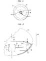
- FIG. 1is a diagrammatic view of apparatus in accordance with one embodiment of the invention in conjunction with a portion of a heart and pulmonary vein.
- FIG. 2is a diagrammatic sectional view taken along line 2 — 2 in FIG. 1 .
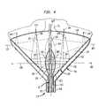
- FIG. 3is a fragmentary diagrammatic view depicting certain geometrical relationships in the apparatus of FIG. 1 .
- FIG. 4is a view similar to FIG. 1 , but depicting apparatus according to a further embodiment of the invention.
- FIGS. 5 , 6 , 7 and 8are fragmentary diagrammatic views depicting apparatus according to further embodiments of the invention.
- FIG. 9is a view similar to FIG. 1 , but depicting apparatus according to yet another embodiment of the invention.
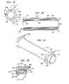
- FIG. 10is a fragmentary, diagrammatic perspective view depicting apparatus according to a further embodiment of the invention.
- FIGS. 11 and 12are fragmentary, diagrammatic sectional views depicting apparatus according to further embodiments of the invention.
- FIG. 13Ais a fragmentary perspective view depicting apparatus according to yet another embodiment of the invention.
- FIG. 13Bis a fragmentary, diagrammatic sectional view depicting apparatus according to another embodiment of the invention.
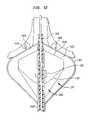
- FIGS. 14 and 15are fragmentary, diagrammatic sectional views depicting apparatus according to further embodiments of the invention.
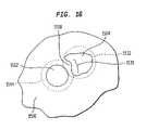
- FIG. 16is a diagrammatic plan view depicting a portion of the interior wall of a cardiac atrium.
- FIGS. 17 and 18are fragmentary perspective views depicting apparatus according to yet another embodiment of the invention during different phases of operation.
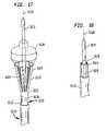
- FIG. 19is an end view of a transducer used in an embodiment of the invention.
- FIG. 20is a sectional view of the transducer of FIG. 19 .
- FIG. 21is a perspective view of a part of the transducer of FIGS. 19 and 20 .
- FIG. 22is a fragmentary view on an enlarged scale of the area indicated in FIG. 20 .
- FIG. 23is a fragmentary sectional view of apparatus according to an embodiment of the invention incorporating the transducer of FIGS. 20–22 .
- FIGS. 24 and 25are perspective view of apparatus according to a further embodiment of the invention.
- Apparatusincludes a probe structure 10 having a proximal end 12 and a distal end 14 . A portion of the probe structure between the proximal and distal ends is omitted in FIG. 1 for clarity of illustration.
- the probe structureincludes a tubular first catheter 16 , a tubular second catheter 18 surrounding the first catheter and a tubular guide catheter 19 extending within the first catheter.
- the first catheter 16carries a cylindrical ultrasonic transducer 20 adjacent its distal end.
- the cylindrical ultrasonic transducermay be a ceramic piezoelectric element such as lead titanate or a polymeric piezoelectric transducer such as PVDF-TRF (polyvinyledene fluoride-trifluoroethylene) copolymer transducer.
- a ceramic piezoelectric transducertypically is formed as a single hollow cylinder of ceramic piezoelectric material with thin metallic electrodes (not shown) disposed on its interior and exterior surfaces.
- a cylindrical polymeric piezoelectric transducermay include one or more layers of polymeric piezoelectric material with electrodes between each pair of adjacent layers and further electrodes on the interior and exterior surfaces.
- a polymeric piezoelectric transducertypically is provided with a rigid backing on its interior surface as, for example, a metallic or ceramic tube (not shown).
- the electrodes of transducer 20are connected to electrical conductors (not shown) extending within or along first catheter 16 to a connector 22 at the proximal end of the first catheter.
- the first catheter and the cylindrical transducer 20define a central axis 24 adjacent the distal end of the probe structure.
- the first catheterhas a distal tip 26 projecting distally beyond the transducer 20 .
- a first balloon 28also referred to herein as a “structural balloon,” is mounted to the first catheter at the distal end thereof.
- the first balloonincludes an active wall 32 formed from film which is flexible but which can form a substantially noncompliant balloon structure when inflated. Materials similar to those used to form noncompliant balloons in the angioplasty art, such as films of PET, PETG, nylon, polyurethane, polyethylene and other polymers can be used.
- such balloonsare inflated to a relatively high preselected inflation pressure, referred to herein as the “design inflation pressure”, such as a few atmospheres to 10 or 12 atmospheres. Inflation pressures of this order render the balloon relatively rigid. Stated another way, the balloon will assume a predictable, preselected shape when inflated to the design inflation pressure, with minimal deviation from this shape despite variations in external pressure applied by the surrounding blood and soft tissue.
- the balloon walldesirably has the minimum thickness required to withstand the design inflation pressure without rupturing, as, for example, about 0.001 inches (1 mil) or less, preferably about 0.5 mils or less. In the inflated condition of the balloon depicted in FIG.
- wall 32is in the form of a surface of revolution about a central axis 24 .
- the largest diameter of the balloondesirably is about 24–28 mm.
- the forward wall 30may be formed from the same materials as wall 32 or from a different material. Preferably, however, the entire balloon is formed as an integral unit from a single material, as by blow-molding a tube or parison of PET or other polymer.
- the forward wall 30is generally annular and has a central opening 34 surrounding central axis 24 .
- the forward wall 30may be generally conical or dome-shaped and may project forwardly from its juncture with active wall 32 .
- the forward wall 30may be conical, with an included angle of about 120 degrees.
- the forward wall 30joins the wall of first catheter 16 at the distal tip 26 thereof, whereas the active wall 32 joins the wall of the catheter 16 proximally of the transducer 20 .
- the transducer 20is disposed inside of first balloon 28 .
- the shape of active wall region 32 depicted in FIG. 1may be that of a surface of revolution about central axis 24 formed by rotation of a generatrix or curve 38 ( FIG. 3 ) which is a portion of a parabola 40 having its principal axis 42 transverse to and desirably perpendicular to central axis 24 .
- the principal axis 42 of the parabolais a line through the focus 44 of the parabola perpendicular to a line 46 referred to as the directrix of the parabola.
- the parabolais curved such that the distance of any point on the curve to focus 44 is equal to the distance from such point to directrix 46 .
- the forward wall 30lies just to the rear or proximal side of focus 44 .
- the focus 44 of the parabolic generatrixis slightly forward or distal of the forward wall 30 when the balloon is in the inflated condition.
- only one section of generatrix 38 and active region 32is shown in FIG. 3 , it should be appreciated that the focus is disposed in substantially the same location at all positions around central axis 24 .
- the focus 44 of the surface of revolutionis a circle surrounding central axis 24 just forwardly of the forward wall 30 .
- a port 31connects the interior space 29 within the first or structural balloon 28 with the lumen or interior bore 33 of the tubular first catheter 16 .
- the first catheterhas a fitting 48 at its proximal end communicating with this lumen so that a fluid may be introduced into the interior space 29 to inflate the first balloon 28 or withdrawn from the first balloon to deflate it.
- the first balloonis collapsed radially inwardly and closely overlies the exterior of first catheter 16 and transducer 20 .
- a second balloon 50is carried on the distal end of second catheter 18 .
- Balloon 50has a partial wall partially enclosing the interior space 52 within the second balloon.
- the partial wallis disposed slightly to the rear or proximally of the active wall region 32 of the first balloon, so that the partial wall of balloon 50 overlies the active wall region 32 of the first or structural balloon.
- the wall of balloon 50joins the wall of balloon 28 at a juncture 54 near the forward edge of the active wall region 32 .
- the interior space 52 within the second balloon 50is partially bounded by the wall of balloon 50 and partially bounded by the active wall region 32 of balloon 28 .
- the active wall region 32is a common wall forming portions of both the first and second balloons and separating the interior space 29 of the first balloon from the interior space 52 of the second balloon.
- the interior space 52 of the second ballooncommunicates with the lumen 56 within second catheter 18 at a port 57 defined by the distal end of the second catheter and surrounding the first catheter 16 .
- the second catheterhas a fitting 58 at its proximal end, so that a fluid can be introduced into the interior space 52 of the second balloon through port 58 , lumen 56 and port 57 to inflate the second balloon and the fluid can be withdrawn to deflate the second balloon.
- the partial wall of balloon 50may be formed from a material such as a urethane, as, for example, by thermoforming, and may be bonded to the wall of balloon 28 by an adhesive at the forward edge of the partial wall.
- the guide catheter 19extends within the interior lumen 33 of first catheter 16 and extends through the distal tip 26 of the first catheter so that a distal tip 60 of the guide catheter projects through the central opening 34 of the forward wall 30 of the first balloon.
- Guide catheter 19is also hollow and has two lumens (not shown).
- An expansible anchor balloon 62surrounds the outside of distal tip 60 and communications with one lumen of the guide catheter through a port 64 .
- the guide catheteris provided with a fitting 66 communicating with this lumen at its proximal end so that the guide catheter and anchor balloon 62 can be connected to a source of fluid for inflation and deflation.
- the other lumen of the guide catheteris arranged to pass a guide wire 68 .
- guide wire 68is threaded through the circulatory system of a living subject such as a human or other mammalian subject suffering from atrial fibrillation and into the interior space 70 within the left atrium of the subject's heart.
- the guide wireis further threaded into a pulmonary vein 72 .
- the proximal end of the guide wire, outside of the patient's body,is disposed in a lumen of guide catheter 19 .
- Anchor balloon 62is inflated with any suitable fluid such as saline solution to expand the anchor balloon and anchor it in a place within the pulmonary vein. This anchors the first and second balloons within the heart chamber 70 .
- the forward wall 30 of the first balloonbears on the interior surface of the heart wall at the ostium or opening 74 at which pulmonary vein 72 communicates with heart chamber 70 .
- the first balloon 28is inflated with water, saline solution or other aqueous fluid having acoustic impedance close to the acoustic impedance of body tissues.
- the second balloon 50is inflated by filling its interior space 52 with a relatively small amount of gas such as carbon dioxide.
- the pressure within the interior space 29 of the first balloonis adjusted to the design inflation pressure of the first balloon. This pressure is substantially above the prevailing pressures within the heart and assures that the first balloon, and particularly active surface 32 , is in its preselected configuration.
- the pressure within the second balloonis selected to be less than the pressure within the first balloon but still above the prevailing pressures within the heart. Any appropriate sources of liquid and gas can be used to inflate the first balloon.
- a controlled-pressure sourceincorporating any convenient type of pressure regulator may be employed.
- the pressure within the interior space 52 of the second balloonis not critical; any gas pressure sufficient to push the wall of balloon 50 away from the active wall region 32 of the first balloon, but not so great as to rupture the second balloon may be employed.
- the aqueous liquid within the interior space 29 of the first balloon and the gas within the interior space 52 of the second balloonform a reflective interface at the active wall region 32 , i.e., at the common wall separating the interiors of the first and second balloons.
- Ris the reflectivity of the interface
- Z 29is the acoustic impedance of the fluid within the interior space 29 of the first balloon 28 ;
- Z 52is the acoustic impedance of the fluid in the interior space 52 of second balloon 50 .
- Acoustic impedanceis sometimes described as the acoustic velocity or speed of sound in a medium multiplied by the density of the medium. More accurately, acoustic impedance is defined as the acoustic pressure divided by the volume velocity. Volume velocity is the velocity that the particles in the medium are moving. Typical aqueous fluids have acoustic impedance of about 1.5 MRayls, whereas typical gases have acoustic impedance of less than about 10 ⁇ 4 MRayls, so that the reflectivity at the active region or interface 32 typically is at least about 0.9 and more typically nearly 1.0.
- Transducer 20is connected to a source 78 of electrical excitation signals through connector 22 and the transducer is actuated to produce ultrasonic waves.
- the ultrasonic wavespropagate substantially radially outwardly as indicated by arrows 80 in FIGS. 1 and 3 .
- the cylindrical transducerproduces substantially cylindrical wave fronts which propagate generally radially outwardly. These waves are reflected by the interface at active region 32 . Because the interface has a parabolic shape, the waves striking any region of the interface will be reflected substantially to the focus 44 defined by the surface of revolution, i.e., into a substantially annular or ring-like focal region at focus 44 . As best seen in FIG.
- this ring-like focussurrounds the central axis 24 and surrounds the ostium 74 of the pulmonary vein.
- This focal regionis slightly forward of the forward wall 30 and hence within the heart tissue, near the surface of the heart wall.
- the focal regionmay be disposed at a depth equal to about one-half of the thickness of the heart wall as, for example, about 2–4 mm from the surface of the wall. Because the fluid within the interior of balloon 29 has an acoustic impedance close to that of the heart tissue itself, there is a minimal reflection at the interface between the forward wall 30 of the first balloon and the heart wall; substantially all of the ultrasonic energy reflected from the active region 32 passes into the heart wall and to the focal region 44 .
- the total distance traveled by the acoustic waver, radially outwardly from the cylindrical surface of transducer 20 to the active region 32 and from the active region to the focus 44is the same for any waves emanating from any axial position along the length of transducer 20 . Therefore, the ultrasonic energy from various portions of the cylindrical transducer will constructively reinforce ultrasonic energy from other portions of the transducer. That is, the wave front from various portions of the transducer will arrive at the focal region substantially in phase with one another. Therefore, the heart wall tissue within focal region 44 will be heated rapidly. The rapid heating effectively ablates or kills the tissue within the focal region so that a wall of non-conductive scar tissue forms in the focal region and in neighboring tissue.
- tissueshould be ablated through the entire thickness of the wall, so as to form a transmural lesion.
- a transducercapable of emitting about 15 Watts of acoustic energy
- an ablated region extending entirely through the heart wallcan be formed within a few minutes of actuation.
- Higher power levelsas, for example, above 30 Watts of acoustic energy and desirably about 45 Watts are preferred because such power levels will provide shorter lesion formation time. Because the sonic energy is directed simultaneously into the entire loop-like path surrounding the pulmonary vein, the entire procedure can be performed without repositioning the probe.
- Ultrasonic heating and ablationoffer numerous advantages over conventional RF heating.
- ablation around the ostiumto place the ablated region in the atrial wall, rather than inside the pulmonary vein, avoids damage to the delicate structure of the pulmonary vein and thus entirely avoids or minimizes stenosis of the pulmonary vein.
- the focal regiondesirably has a diameter of about 25–30 mm.
- the various balloonsare deflated and the entire apparatus is withdrawn.
- Apparatusincludes a probe structure incorporating a first catheter 116 and a second catheter 118 , together with a first balloon 128 and second balloon 150 similar to the corresponding elements discussed above with reference to FIGS. 1–3 .
- the active region 132 in its inflated conditiondoes not have a parabolic configuration. Instead, the active surface is substantially conical and concentric with the central axis 124 of the sonic transducer 120 and probe structure 110 .
- the common wall 132 between the interior space 129 of the first balloon and the interior space 152 of the second balloonslopes forwardly at a substantially constant angle to the central axis.
- Sonic transducer 120is carried on an additional catheter 101 slidably mounted within the first catheter 16 .
- the additional catheterhas a central bore 102 and an auxiliary bore 103 .
- a guide catheter 160is received within the central bore 102 of the additional catheter.
- the guide catheteris sealed to the forward wall 130 of the first balloon.
- An additional balloon 104surrounds the cylindrical sonic transducer 120 .
- the additional balloon 104is formed from a flexible material such as those discussed above with reference to the active region of the first balloon. Thus, balloon 104 has a predictable, preselected shape when inflated.
- Balloon 104in a fully inflated condition, has a shape of surface of revolution about central axis 124 .
- balloon 104is also referred to herein as the “lens balloon.”
- Lens balloon 104communicates with the auxiliary bore 103 of additional catheter 101 .
- the additional catheter 101 , transducer 120 and lens balloon 104are slidable in the axial or proximal and distal directions relative to the first catheter 116 , guide catheter 160 and first balloon 128 .
- the apparatusis placed in substantially the same way as discussed above.
- the first and second cathetersare inflated by placing a liquid into the interior space 129 of the first balloon through the lumen of first catheter 116 and by introducing a gas through the lumen of second catheter 118 into the interior space 152 of the second balloon in substantially the same way as discussed above.
- Lens balloon 104is inflated through additional lumen 103 of catheter 101 with a fluid having an acoustic velocity less than that of the aqueous liquid within interior space 129 of the first balloon but having an acoustic impedance close to that of the liquid in space 129 .
- fluorocarbon liquids sold under the registered trademark FLUORINERThave acoustic velocity less than that of water but have acoustic impedance close to that of water.
- the acoustic emitter 120 and lens balloon 104are actuated as discussed above.
- the acoustic emitteremits acoustic waves which propagate substantially radially within lens balloon 104 as indicated by arrows 180 in FIG. 4 .
- these wavesencounter the interface between the fluid in lens balloon 104 and the fluid in the interior space 129 of the first balloon, they are refracted into a convergent pattern indicated by arrows 181 .
- the convergent acoustic wavesare focused towards an annular focus 106 on medial plan 105 , concentric with the central axis 124 . Because the acoustic impedances on the inside and outside of lens balloon 104 are well matched, there is only minimal reflection of ultrasonic waves at this interface.
- the apparatusapplies thermal treatment to a portion of the tissue in the heart wall in the focal region 144 so as to ablate the tissue in and around the focal zone.
- the tissueis ablated along the substantially closed ring-like path encircling the ostium of pulmonary vein 72 , and the thermal treatment is performed at substantially all points along the path simultaneously.
- the sonic emitter 120 and lens balloon 104may be moved axially within the interior of first balloon 120 to the position indicated in broken lines at 104 ′ and the sonic emitter may be actuated again.
- the outwardly propagating ultrasonic wavesare focused towards medial plane 105 ′. Accordingly, the ultrasonic waves intersect the active region 132 of the reflector at a relatively large radius from central axis 124 , so that the reflected ultrasonic waves are focused at a different focal region 144 ′.
- Focal region 144 ′is a ring-like region encircling the central axis 124 at a larger radius than the original focal region 144 .
- the tissue surrounding region 144 ′may be subjected to the thermal treatment.
- the tissue in a loop-like path encircling the ostium of the pulmonary veinis treated.
- the emitting element and lens balloonmay be moved to positions between the position indicated in solid lines and the position indicated in broken lines so as to bring the ultrasonic waves into focus in a ring-like focal region having a radius larger than that of focal region 144 but smaller than that of focal region 144 ′. Any number of such intermediate positions can be used so as to apply thermal treatment over any number of different focal regions.
- the lens balloon and sonic emitterare moved over a range of positions while the sonic emitter operates continuously, so as to spread the applied sonic energy over a range of focal regions.
- a cylindrical emitting element and a lens balloonis replaced by an emitting element 220 substantially in the form of a surface of revolution but having sloping emitting surfaces 221 and 222 tilted towards a common medial plane 205 transverse to the central axis 224 of the emitting element so that these emitting surfaces will emit ultrasonic waves converging towards the medial plane 205 .
- a non-cylindrical emitting elementmay be formed as a unitary mass of a ceramic or other rigid piezoelectric material.
- such an emitting elementmay be formed from one or more strips of a flexible piezoelectric material. Such strips may be wound into a spiral so that in a contracted condition the strip lies close to the central axis 224 . When expanded the spiral strip or strips form a body of revolution having emitting surfaces lying generally along a surface of revolution about the central axis 224 .
- Such a spiral-shaped transducermay include plural strips of piezoelectric material having emitting surfaces tilted in a different directions disposed on opposite sides of a medial plane 205 .
- such a transducermay be expanded or contracted by a further balloon 201 disposed inside of the spiral-wound piezoelectric material.
- the focusing functionis performed entirely by the active region 32 of the reflector structure, so that the reflector structure both focuses and redirects the sonic energy.
- the focusing functionis performed entirely by the lens balloon or the ultrasonic emitter and the reflector structure serves principally to redirect the sonic energy without further focusing it.
- some focusingis provided by a shaped transducer or lens and the reflector structure further focuses the ultrasonic energy.
- an emitting assembly 320FIG.
- the central axis 324such as a cylindrical emitter and lens as discussed above with reference to FIG. 4 or a shaped emitter as discussed with reference to FIG. 5 , provides ultrasonic waves converging towards a medial plane 305 transverse to the central axis.
- the active region 324 of the reflector structureis shaped so that the reflected ultrasonic waves will be directed substantially along cylindrical paths which do not further converge.
- the reflector structureacts to collimate the reflected ultrasonic waves in a beam 383 having a shape of a hollow cylinder with a relatively small radial thickness.
- the ultrasonic waves directed into the wall 370 of the heartare not focused by the reflector structure.
- the ultrasonic waves from the entire transducerare concentrated into a correspondingly small cross-sectional area of the axial beam 383 , so that substantial ultrasonic power is concentrated within a narrow ring-like path over the pulmonary vein 372 .
- the ultrasonic poweris spread more evenly through the thickness of the heart wall in the axial direction.
- Apparatus according to yet another embodimentincludes a reflector structure which incorporates only a single balloon 428 .
- the balloonis inflated with a gas or other medium having acoustic impedance substantially different from the acoustic impedance of blood or other aqueous fluid found within the interior of the heart chamber 470 .
- the emitting assembly 470is disposed outside of the first balloon so that acoustic waves traveling from the emitting assembly pass through the blood or other aqueous fluid contained within chamber 470 to the active region 432 of the reflector structure. Due to the impedance mismatch between the blood or other aqueous fluid and the gas inside balloon 428 , there will be highly reflective interface at the active region 432 .
- the ultrasonic energyis reflected forwardly from the active region.
- the reflected beammay be convergent towards a focal region or may be collimated in a beam having the shape of a hollow cylinder.
- Apparatusincludes three balloons defining three interior spaces 529 , 550 and 555 so that there is a first interface 532 between the first and second balloons and a second interface 533 between the second and third balloons, behind the first interface.
- first balloonis inflated with a liquid such as an aqueous liquid
- second balloonis inflated with a gas or other medium having acoustic impedance different from that of the liquid
- the ultrasonic waves from emitting assembly 520will be reflected at the first interface 532 .
- the fluid in the interior space 555 of the third balloondoes not play any appreciable role in operation of the reflector structure.
- the interior spaces 529 and 550are filled with liquids having substantially similar acoustic impedances, whereas the interior space 555 of the third balloon is filled with a gas or other fluid having substantially different acoustic impedance from the fluids in the first and second interior spaces.
- the interior space 555 of the third balloonis filled with a gas or other fluid having substantially different acoustic impedance from the fluids in the first and second interior spaces.
- there will be little or no reflection at the first interface 532whereas there will be substantial reflection at the second interface 533 .
- either interface 532 or interface 533may serve as the active region of the reflective structure. This approach can provide reflective structures of different configurations and in different relationship to the emitting assembly 520 .
- the focus or direction of the acoustic energymay be varied during operation by changing the fluids used to inflate the second balloon, so as to direct the acoustic energy into different regions of the organ to be treated as for example, into a deeper or shallower focus in the wall of the heart.
- a structuresuch as discussed above with reference to FIG. 1 , which provides a focus at a substantially fixed location relative to the reflector structure can be moved so as to bring the active region of the reflector structure towards or away from the wall of the heart and thereby vary the depth of focus within the heart wall.
- the reflector structuremay be slidable with respect to the anchor 62 and guide catheter 60 .
- the configuration of the reflector structuremay be arranged so that movement of the emitter structure relative to the reflector structure, such as the movement discussed above with reference to FIG. 4 , varies the depth of focus instead of the radial location of the focal region, or varies both the radial location and depth of the focal region.
- Apparatusincludes a reflector structure incorporating single balloon 628 having an active region 632 formed from an optically-reflective material such as a metalized polymer film.
- the forward wall 630 of balloon 628is formed from a material which is transparent or translucent to optical radiation in a predetermined band of wavelengths as, for example, red or infrared light.
- An optical wave guide in the form of a fiber optic 602extends through the probe structure to the proximal end of the probe structure (not shown).
- a source reflector 603is mounted within the first balloon on a support 604 mounted to the forward wall 630 so that when the first balloon is in the inflated condition as shown in FIG. 9 , the reflector is aligned with the distal end 606 of the fiber optic.
- the interior space within the first balloonis filled with a fluid such as a gas transparent to the optical radiation to be applied.
- the proximal end of fiber optic 602is connected to a laser or other source of light such as a red or infrared emitting laser.
- Light transmitted through the fiber opticimpinges on source reflector 603 and is redirected from the source reflector onto the active region 632 of the inflatable reflector structure.
- the reflected lightis focused or directed into a loop-like path encircling the central axis 624 and is directed into the wall of the heart in a loop-like region 644 surrounding the central axis 624 and surrounding the ostium of the pulmonary vein.
- energyis applied to the entire loop-like region simultaneously.
- the active region of the reflector structuremay be arranged to focus the optical energy or to redirect it in a substantially collimated beam having the cross section of a hollow cylinder.
- some focusingcan be performed by the source reflector 603 or by a lens (not shown) surrounding the source reflector.
- the acoustical emitters discussed above with reference to FIGS. 1–8can be replaced by acoustic wave guides in the probe structure for conducting ultrasonic energy from a sonic source at the proximal end of the probe structure to the reflector structure.
- Such an arrangementcan include a source reflector similar to the optical source reflector 603 of FIG. 9 for directing the ultrasonic energy radially outwardly.
- the guide catheter and anchor illustrated in FIG. 1may be omitted as shown, for example, in FIGS. 5 , 6 and 8 .
- a guide cathetermay be employed without an anchor.
- placement of the reflector structure in the appropriate location on the heart wallis verified by imaging and/or location-finding techniques before energy is applied to perform the thermal treatment.
- some portions or all of the probe structuremay be formed from a material which is visible in an imaging technique such as, for example, a radiopaque material for use in fluoroscopic, CAT or conventional X-ray imaging.
- the reflector structureitself is visible in an imaging modality.
- a balloon filled with air or other gaswill be readily visible in a magnetic resonance imaging procedure or in an ultrasonic imaging procedure, whereas a balloon filled with a liquid X-ray contrast agent is visible using fluoroscopy.
- the probe structuremay carry a small antenna 607 for receiving magnetic resonance signals from tissues surrounding the balloon.
- a local antenna 609may be formed on the surface of a balloon included in the reflector structure.
- Such local antennasare connected by leads (not shown) extending to the proximal end of the probe structure which in turn are connected to the RF signal receiver of a magnetic resonance measurement or imaging device.
- Use of such a local antennaprovides magnetic resonance signals from the tissue adjacent the balloon with a relatively high signal to noise ratio and thus facilitates the magnetic resonance measurement or imaging process.
- the apparatusacts to direct the applied energy into an annular region.
- the reflector structuremay direct the energy into a region of a different shape.
- an elongated reflector structure extending lengthwise along a dual-lumen catheter 901has a first chamber 928 filled with a liquid and a second chamber 950 filled with a gas, so as to form a reflective active region 932 at a wall between these chambers.
- An elongated emitting element 920is arranged to direct ultrasonic energy onto the active region, so that the energy will be focused onto an elongated focal region 944 extending parallel to the catheter.
- the emitting element and reflector structuremay be arranged similarly to those discussed above with reference to FIGS. 1–9 , but may have shapes other than surfaces of revolution so as direct the energy into a non-circular region.
- the focal regionneed not form a closed annulus or loop, but instead may form a partial loop or other elongated path, a spot, or any arbitrary shape.
- a shieldmay be mounted alongside the emitting element in a structure as shown in any of FIGS. 1–9 , so that the shield extends generally parallel to the central axis of the emitting element and blocks emission of energy in certain radial directions.
- Such a shieldmay be mounted in a fixed position relative to the remainder of the device, or else may be rotatable around the axis by a cable extending through the probe structure, so that the position of the shield may be varied.
- the reflectivity of the active region in the reflector structuremay be selectively controllable in each of several zones distributed around the axis.
- the second balloon 50 of FIG. 1may have its interior space 52 subdivided into several zones spaced circumferentially around the central axis, each such zone being connected to a separate lumen so that each zone can be independently inflated with either a liquid or a gas.
- the active region 32 or interface with the first balloonwill be non-reflective in those zones where the second balloon contains a liquid, but will be reflective in those zones where the second balloon contains a gas.
- the emittermay have a plurality of signal electrodes spaced around its circumference, and leads may be provided for independently applying excitation signals to the electrodes so as to actuate the emitter over any selected part of its circumference.
- the forward-facing transmissive wall 30 of the first or structural balloon 28abuts the tissue of the heart wall when the apparatus is in the operative condition.
- This abutmentholds the expansible structure at a known location relative to the tissue to be ablated and helps to assure that the focal location will lie at the desired depth relative to the surface of the heart wall.
- the first or structural balloon 1028has a transmissive wall 1030 in the form of an annulus surrounding central axis 1024 .
- An abutment projection 1002extends forwardly from the transmissive wall on the inside of the annulus, adjacent central axis 1024 .
- a generally cylindrical locating projection 1006extends forwardly from the abutment wall 1004 .
- Locating projection 1006has a conical lead-in wall 1008 at its forward end.
- the abutment projection 1002 and locating projection 1006are formed as portions of the first or structural balloon 1028 . This balloon is mounted on a carrier catheter 1010 adjacent the distal end of the carrier catheter.
- an ultrasonic transducer 1020is mounted inside the first or structural balloon 1028 .
- a second or reflector balloon 1050is also carried on catheter 1010 .
- structural balloon 1028is inflated with a liquid such as an aqueous liquid having acoustic impedance close to that of water and bodily tissue.
- Reflector balloon 1050is inflated with a gas having acoustic impedance substantially lower than that of the liquid in the structural balloon, so as to form an acoustic reflective interface at the common wall 1032 separating the interior spaces of these balloons.
- balloons 1028 and 1050cooperatively form an expansible reflector structure.
- Carrier catheter 1010is advanced into the heart and the distal tip of the carrier catheter is threaded into a pulmonary vein 1072 .
- the locating projection 1006seats in the lumen of the pulmonary vein and centers the assembly with respect to the ostium of the pulmonary vein.
- the abutment wall 1004engages the tissue immediately surrounding the opening of the pulmonary vein.
- the abutmentlocates the expansible reflector structure and, hence, the reflecting interface 1032 at a predetermined location in the forward-to-rearward or distal-to-proximal direction along axis 1024 , leaving a space 1012 between transmissive surface 1030 and the tissue surface at the focus 1044 .
- the spaceis filled with the blood present in the heart.
- the acoustic energy from transducer 1020is reflected at interface 1032 and focused by the reflective interface onto the loop-like focal region 1044 in substantially the manner discussed above with reference to FIG. 1 .
- space 1012is filled with blood having acoustic impedance and acoustic velocity close to the aqueous fluid within balloon 1028 , the space does not materially affect the ultrasonic transmission.
- the presence of a layer of liquid at the surface of the tissuehelps to assure reasonably uniform heat transfer from the tissue surface.
- abutment projection 1002 and guide projection 1006need not be formed integrally with the structural balloon. These elements can be formed as separate balloons carried on carrier catheter 1010 or otherwise physically linked to the expansible structure defining the reflective surface. Also, the abutment structure need not provide a continuous abutment wall encircling the central axis 1024 .
- the abutment structurecan be formed by a set of arms or other mechanical elements, which project outwardly from the carrier catheter in the operative condition. Alternatively or additionally, abutment elements can be provided around the outside of the transmissive wall, i.e., further from the central axis than the transmissive wall.
- the embodiment depicted in FIG. 12includes an expansible reflector structure 1127 with a structural balloon having a transmissive surface 1130 , and with a reflector balloon 1150 , similar to those discussed above, defining a reflective interface 1132 , as well as a sonic transducer 1120 . These elements are similar to the corresponding elements of the embodiments discussed above.
- the expansible reflector structureis surrounded by an expansible basket 1102 formed from a set of wires.
- the expansible basketmay be actuated by an actuator catheter 1104 slidably mounted in the carrier catheter 1110 . By retracting the actuator catheter 1104 rearwardly relative to the carrier catheter 1110 , the expansible basket may be brought to the expanded condition illustrated.
- the basket structureholds the expansible reflector structure 1127 at a predetermined distance from the surface of the cardiac wall and, thus, serves as a standoff, so as to provide a space 1112 between the transmissive wall and the tissue.
- the basket structureincludes relatively few wires extending across the path or ablation region, and these wires are of the smallest practical diameter, so that they do not materially interfere with the ablation procedure.
- the basket structurealso may carry sensing electrodes 1106 and 1108 .
- each of the wiresmay be covered with a substantially continuous electrical insulating coating, except at those locations, which are to serve as electrodes.
- the wiresare connected by conductors (not shown) to conventional electrophysiologic potential monitoring equipment. Although only two electrodes are depicted in FIG. 18 , the set of electrodes used for physiologic potential monitoring may include more than two electrodes.
- Electrophysiologic potential monitoringcan be used to monitor and to control the ablation procedure.
- the electrophysiologic potentialpropagates along the wall of the heart.
- electrodes disposed at different locations on the cardiac wallwill be exposed to differing potentials at any given time.
- the pattern of change in these differencesrepresents the propagating electrophysiologic potential. If the ablation forms a complete conduction block extending along a closed, loop-like path, the region inside of such loop-like path will be isolated from the potential propagating in the rest of the heart.
- Electrodes 1106 and 1108are disposed at locations closer to the central axis 1124 than the ring-like focal region 1144 , so that these electrodes will engage the cardiac tissue at locations inside of the ring-like ablation region formed by the focused energy.
- the electrical signal appearing across these two electrodeswill have a component having a fixed phase relationship to the electrophysiologic signal in the rest of the heart.
- the potential propagating in the heart outside of the ablation regioncan be detected by further electrodes (not shown), or by conventional electrocardiographic (“ECG”) techniques.
- ECGelectrocardiographic
- the signal appearing across electrodes 1106 and 1108will change and will no longer have a component linked to the signal in the rest of the heart. This change can be detected during application of the sonic energy, and application of the sonic energy can be terminated once a complete conduction block has been achieved, as shown by the change in the electrical signals.
- the ultrasonic or other energy used for ablationcan be applied for a first predetermined period, and then terminated. Following this first period, the electrophysiologic potential can be monitored. If the block is complete, the process is terminated. If not, the process is repeated.
- Apparatus according to a further embodiment of the inventionincludes an expansible balloon structure 1227 having a pair of ring-like monitoring electrodes 1206 and 1208 disposed on the forward or transmissive wall 1230 .
- These electrodesdesirably are formed by thin metallic coatings, as, for example, sputtered, electroless-plated or electroplated gold.
- the forward or transmissive wall 1230 of the balloon structureis arranged to contact the cardiac wall, at least in the region encompassed by electrodes 1206 and 1208 .
- a guide projection 1210 similar to the guide projection 1106 discussed above with reference to FIG. 11projects forwardly from wall 1230 and enters into the ostium of the pulmonary vein during use.
- the distal end 1212 of the expansible balloon structurein this case the distal end of guide projection 1210 , is mechanically connected to a guide catheter 1214 slidably mounted in carrier catheter 1216 .
- the proximal end 1213 of the expansible balloon structureis mechanically connected to the carrier catheter 1216 . Both of these catheters extend rearwardly to the proximal end of the probe (not shown).
- Electrodes 1206 and 1208are connected by conductors 1207 and 1209 extending along the balloon structure to conductors (not shown) extending within guide catheter 1214 . These conductors convey the electrical signals to electrophysiologic monitoring instruments (not shown) at the proximal end of the probe, outside of the patient's body.
- the guide catheter and carrier catheteralso can be manipulated during use to facilitate collapse of the balloon structure after operation and withdrawal of the balloon structure.
- the balloon structureis supplied by the manufacturer in a fully-collapsed condition, so that the structure has a small diameter.
- the carrier catheter 1216 and some portion or all of the balloon structure 1227may be housed within the interior bore of an introducer catheter 1218 .
- the introducer catheterhas an opening 1220 at the distal end of the internal bore.
- the introducer catheteralso extends to the proximal end of the probe.
- the balloon structureis expanded and inflated to the operative condition illustrated in FIG. 13A .
- the distal end 1212 and, hence, guide catheter 1214are drawn rearwardly or proximally relative to the proximal end 1213 and carrier catheter 1216 .
- the balloon structureis collapsed by withdrawing fluid from the interior of the structure.
- the physiciancan manipulate the guide catheter and carrier catheter, so as to move the guide catheter and distal end forwardly or distally relative to the proximal end 1213 and carrier catheter, as by advancing the guide catheter 1214 relative to the introducer catheter 1218 , while leaving the carrier catheter in fixed position relative to the introducer catheter; by retracting the carrier catheter while leaving the guide catheter in fixed position, or by moving both the guide catheter and the carrier catheter.
- the physicianalso may twist the guide catheter relative to the carrier catheter so as to twist the balloon structure during collapse.
- the ballooncan be twisted without deliberate axial elongation.
- the balloon structurecan be withdrawn back into the interior bore of introducer catheter 1218 by pulling the carrier catheter 1216 rearwardly. Minimizing wrinkling and providing an orderly collapse facilitates re-entry of the balloon structure into the distal end of the introducer catheter.
- a resilient elementsuch as a small coil spring 1250 may be provided within the balloon structure.
- the resilient elementis arranged so that it tends to force the distal end 1212 of the balloon distally or forwardly relative to the proximal or rearward end 1213 of the balloon.
- the resilient disposed within the balloon structureis compressed between the distal end of the balloon and the proximal end when the balloon structure is inflated.
- the proximal end of the coil springrests against the distal end of the transducer 1220 , which in turn is mechanically linked to the proximal end 1213 of the balloon structure and to the carrier catheter 1216 .
- resilient element or spring 1250When the fluid pressure within the balloon structure is released and the structure deflates, resilient element or spring 1250 will force the distal end of the balloon away from the proximal end.
- Other forms of resilient elementmay be employed, as, for example, a compressible, elastomeric tube surrounding the guide catheter.
- the use of a resilient elementmakes it unnecessary to transmit motions through the carrier catheter and guide catheter during the deflation process. This facilitates the use of a relatively soft, limber carrier catheter, with a similarly limber guide catheter, or with no guide catheter at all. This, in turn, can facilitate positioning of the apparatus within the heart.
- the carrier cathetermay have a highly flexible region forming a flexible joint disposed immediately proximal to the balloon.
- the springmay be arranged so that the coils of spring 1250 ′ engage one another so as to form a column which has appreciable stiffness in bending transverse to the axis of the spring when the spring is in the axially-collapsed or compressed state depicted in FIG. 13B .
- the coils of a conventional coil springmay be formed from square wire.
- the coilsmay be arranged to nest fully or partially within one another when the spring is collapsed axially.
- Such a springis commonly referred to as a “volute” spring.
- the proximal end of the springis mechanically coupled to the carrier catheter 1216 .
- the proximal end 1251 ′ of the springis mounted to the distal end of an elongated energy emitter such as an ultrasonic transducer as discussed above, and the proximal end of the emitter is mechanically connected to the carrier catheter 1216 ′.
- the springis substantially coaxial with the emitter, and the axes of these components coincide with the central axis 1224 ′ of the carrier catheter distal end.
- the distal end 1253 ′ of the springis connected to the distal end 1212 ′ of the balloon, whereas the proximal end 1213 ′ of the balloon is connected to the carrier catheter.
- the springthus resists movement of the distal end of the balloon relative to the proximal end transverse to the central axis, and maintains the orientation of the balloon relative to the carrier catheter and, particularly, relative to the emitter. This helps to maintain the shape of a reflecting surface defined by the balloon during use, and also helps to maintain alignment between the balloon and the emitter.
- the springis used without the guide catheter 1214 shown in FIG. 13A .
- Apparatus according to a further embodiment of the inventionincludes an expansible structure 1327 , including a first or structural balloon 1328 and a second or reflector balloon 1350 , similar to those discussed above.
- the structural balloonhas a forwardly-facing transmissive wall 1130 .
- a guide structure 1331projects from the forward or transmissive wall 1330 .
- the guide structuredoes not limit forward motion of the inflated balloon structure.
- the transmissive wall 1330is made porous.
- the transmissive wallhas an array of ports 1314 distributed over the transmissive wall.
- the portsare provided in the portion of the transmissive wall that immediately overlies the annular focal location 1344 , or in neighboring areas of the transmissive wall.
- ports 1314are shown in FIG. 20 as discrete holes for clarity of illustration, the ports may be microscopic.
- suitable portscan be formed in the wall of a polyethylene terepthalate (“PET”) balloon by laser ablation of the balloon wall.
- PETpolyethylene terepthalate
- a biocompatable inflation liquidas, for example, an isotonic saline solution, is introduced into the structural balloon 1328 through a lumen in the probe structure, as, for example, the lumen of the carrier catheter 1310 .
- the fluidflows through the interior space of the structural balloon and out through ports 1314 , so as to form a liquid layer between the transmissive wall and the cardiac tissue at focal region 1344 .
- the transmissive walldoes not contact the cardiac tissue at the focal region. Nonetheless, the reflective interface is maintained at a precise location relative to the surface of the cardiac tissue.
- Ports 1314desirably have substantial resistance to flow, so that a substantial internal pressure is maintained within the interior space of structural balloon 1328 at a moderate flow rate of liquid through the balloon.
- the flowing liquiddesirably is introduced into the balloon adjacent ultrasonic emitter or transducer 1320 , so that some or all of the flowing liquid will pass over or through the transducer and maintain the temperature of the transducer within desired limits.
- one or more ports 1360can be provided on guide catheter 1331 or on a guide member of the structural balloon which projects distally of wall 1330 . These ports desirably also communicate with the interior space of the structural balloon, or with a lumen (not shown) in a catheter, so that liquid can be supplied to the ports either through structural balloon 1328 or through a separate lumen of the structural balloon.
- the port 1360desirably is located within the annulus defined by the focal region, so that fluid flowing outwardly from the port over the transmissive wall will pass across the focal region and maintain a fluid layer between the transmissive wall and the tissue at the focal region.
- a transmissive liquid layeralso can be used with energy other than ultrasonic energy, provided that the fluid used to maintain the layer is transmissive to the energy applied.
- the fluid layershould be transparent.
- the expansible structureincorporates a structural balloon 1428 having an interior space 1429 , which, in operation, is filled with a liquid and also includes a reflector balloon 1450 having an interior space 1451 filled with a gas during operation as described above, so as to provide a reflective interface or active region at wall 1452 .
- the expansible structurealso includes a reflective redirecting element 1402 in the form of a further balloon having an interior space 1403 , which is filled with a gas during operation. This forms an additional reflective interface 1404 at the wall separating the interior space 1403 of balloon 1402 from the interior space 1429 of the structural balloon.
- the redirecting element 1402is mounted on the probe structure 1410 , so that in use, with all of the balloons inflated, the redirecting element 1402 is juxtaposed with the active region 1452 . Energy reflected from the active region will be directed onto the additional reflective interface 1404 defined by the redirecting element 1402 . The energy is then reflected from this interface onto the focal region.
- the redirecting elementallows the use of a reflector balloon and active region having a more compact configuration.
- the redirecting elementmay be a balloon having a metallic or other light-reflecting surface.
- the reflective interface defined at the redirecting elementmay be shaped so that it further focuses or collimates the energy reflected from it.
- energyis reflected from the redirecting element back onto an additional portion of the reflective interface defined by the same elements which define the active surface, as, for example, onto a further portion of the reflective interface defined between balloons 1450 and 1429 in FIG. 15 .
- the energypasses through three separate reflections in passing from the emitter to the tissue.
- This approachcan be combined with additional focusing or collimating elements, such as refractive elements.
- the topography of the cardiac wallmay make it difficult to ablate a fully-closed loop around the ostium using forwardly-directed energy focused along a loop-like path, as discussed above with reference to FIG. 1 .
- the ostium 1502 of the pulmonary veinis disposed adjacent the atrial appendage 1504 .
- the atrial appendage 1504forms a pocket or recess communicating with the interior of the atrium.
- the tissue of the cardiac wallis recessed within appendage 1504 .
- the tissue in recess 1504lies further from the viewer, as seen in FIG. 16 , than the tissue in the main region 1506 of the atrial wall.
- an additional conduction blockmay be formed along a further path 1512 extending around the atrial appendage and intersecting path 1544 .
- the region of path 1544 where ablation occurs(the region other than region 1510 ) forms a first conduction block extending partially around the ostium of the pulmonary vein 1502 ; whereas, the region along path 1512 forms a second conduction block extending around the opening of the atrial appendage 1504 .
- These conduction blocksintersect one another and form a substantially closed conduction block encompassing both the opening of the atrial appendage and the ostium of the pulmonary vein.
- a second conduction blockmay be formed by ablation using the apparatus discussed above, or by other, conventional techniques.
- a conduction block formed using the apparatus and methods discussed hereincan cooperate with natural conduction blocks, such as the openings of valves in the heart, or with other medically created conduction blocks, so as to provide a composite, closed loop-like conduction block.
- natural conduction blockssuch as the openings of valves in the heart
- other medically created conduction blocksso as to provide a composite, closed loop-like conduction block.
- a partial loop-like conduction blockmay be formed around the ostium of each pulmonary vein using the apparatus and methods discussed above, so that the two partial conduction blocks intersect one another.
- Apparatus according to a further embodiment of the inventionincludes an elongated probe incorporating an introducer catheter 1610 having an interior bore with an opening 1612 at its distal end and a skirt member 1614 slidably mounted within the interior bore of the introducer catheter.
- the skirt memberincludes a tubular body 1616 having an internal bore.
- This bodymay be in the form of a further elongated catheter extending all the way to the proximal end of the probe, so that it can be manipulated directly from outside of the patient's body during use.
- the body 1616may be linked to a guide wire or other member extending within introducer catheter 1610 and capable of transmitting forward and rearward forces.
- Skirt member 1614defines a central axis 1618 , referred to herein as the “skirt axis.”
- the skirt memberincludes a plurality of limbs 1620 disposed around the skirt axis.
- Each limbhas a proximal end 1622 pivotably connected to the body 1616 of the skirt member, and has a distal end 1624 remote from the body.
- the limbsare movable between the collapsed condition seen in FIG. 18 , in which the distal ends of limbs 1620 lie relatively close to the skirt axis 1618 , and an expanded condition seen in FIG. 17 .
- the apparatusfurther includes a carrier catheter 1626 and a balloon 1628 mounted on the carrier catheter.
- the carrier catheteror another catheter included in the probe, has an inflation conduit communicating (not shown) with the interior of the balloon, so that the balloon can be inflated and deflated.
- the particular balloon 1628 illustrated in FIGS. 17 and 18forms part of an expansible structure, as discussed above, for directing energy onto the wall of an internal organ.
- Carrier catheter 1626is slidable in the forward and rearward (distal and proximal) directions relative to skirt member 1614 and introducer catheter 1610 .
- the balloon 1628When the apparatus is initially supplied, the balloon 1628 is surrounded by the limbs of the skirt member and is disposed inside the introducer catheter 1610 .
- carrier catheter 1626After the apparatus has been threaded into the heart or other organ to be treated, carrier catheter 1626 is advanced relative to the skirt member and relative to the introducer catheter, and the balloon is inflated. In this condition, the distal ends of the limbs surround the carrier catheter 1626 .
- the apparatusis brought to the condition illustrated in FIG. 17 .
- the limbs of the skirt membersurround at least the proximal end of the balloon.
- the balloon and carrier catheterare retracted further relative to the skirt member, so that the limbs substantially surround the balloon.
- the balloonis deflated and the carrier catheter and skirt member are retracted relative to the introducer catheter, so that the limbs and balloon enter into the introducer catheter.
- the limbshelp to guide the balloon into the bore of the introducer catheter.
- the introducer catheteris omitted and the skirt member is used as an introducer catheter.
- the distal ends of the limbsare secured in the retracted position by frangible or water-soluble elements (not shown) connecting the distal ends to one another or by an elastic member, such as an elastic band surrounding the limbs or the like.
- an elastic membersuch as an elastic band surrounding the limbs or the like.
- the limbs of the skirt membermay remain partially expanded.
- the limbswill serve to guide the deflated balloon through the vascular system or other tissues of the subject during withdrawal.
- the skirt member and the carrier cathetermay be retracted together to withdraw the apparatus from the patient.
- FIGS. 19–22A preferred ultrasonic transducer or emitter usable in the present invention is depicted in FIGS. 19–22 .
- This transduceris further described in the copending, commonly assigned U.S. patent application Ser. No. 09/904,620, filed Jul. 13, 2001, the disclosure of which is hereby incorporated by reference herein.
- the emitterincludes an active piezoelectric element 1702 in the form of a thin cylindrical tube having an exterior or front surface 1704 and an interior or rear surface 1706 .
- An electrode 1708forms the front surface 1704 of the piezoelectric element, and a similar electrode 1707 forms the rear surface.
- the thickness of the electrodeis greatly exaggerated in FIGS. 20 and 22 for clarity of illustration.
- the electrodepreferably is formed by a thin metallic coating, such as a plated or sputtered coating of metal on the order of a few thousand Angstroms thick overlying the actual piezoelectric material.
- An internal structure 1710includes an inner support tube 1712 and an outer support tube 1714 .
- Support tubes 1712 and 1714desirably are formed from a metallic, electrically conductive material.
- inner support tube 1712has an outwardly projecting shoulder 1720 at one end.
- a similar shoulder 1722is provided at the opposite end.
- Outer support tube 1714has a cylindrical internal bore. Shoulders or rings 1720 and 1722 fit closely within the cylindrical bore of the outer support tube.
- Gap 1726is filled with a gas, such as normal room air, at the time the tubes are sealed to one another. This gas remains permanently within gap 1726 .
- Outer support tube 1714has a pair of outwardly projecting shoulders 1730 and 1732 at the ends of the outer support tube.
- Each shoulderhas arcuate surfaces 1734 connected by flats 1736 , so that each shoulder is generally in the form of a square with rounded corners.
- the arcuate surfaces 1734are concentric with the main portion of the support tube 1714 .
- the flats 1736are tangent to the cylindrical surface of the main portion of the support tube. As best seen in FIG.
- the tubular piezoelectric electric element 1702is supported on the arcuate surfaces 1734 of shoulders 1732 and 1730 , so that the inner surface 1706 of the piezoelectric element is concentric with the outer surface of support tube 1714 , but is spaced apart from the support tube so as to define a space in the form of a tubular passageway 1740 between the outer support tube and the inner or rear surface 1706 of the piezoelectric element.
- Passageway 1740is open to the exterior of the transducer through small gaps 1742 defined between the inner surface 1706 of the piezoelectric element and the flats 1736 of the shoulders on the outer support tube.
- the space or passageway 1740is filled with a liquid.
- the front surface of the emitter(the front surface 1704 of the active piezoelectric element) is acoustically coupled to the medium which is to receive ultrasonic energy from the emitter.
- the emitter of FIGS. 19–22may be used as the ultrasonic emitter 1758 in the apparatus depicted in FIG. 23A .
- This apparatusincludes a probe structure incorporating a carrier catheter 1760 , a structural balloon 1756 having a proximal end connected to the carrier catheter, and a guide catheter 1750 extending through the lumen of the carrier catheter into or through structural balloon 1756 .
- Guide catheter 1750has an internal lumen 1752 and one or more ports 1754 communicating with the interior space of the structural balloon 1756 adjacent the distal end of this balloon and distal to the transducer 1758 .
- the lumen of the carrier catheteris connected to a source 1761 of a liquid such as an aqueous liquid as, for example, water or saline solution, whereas the lumen of guide catheter 1750 is connected to a drain.
- the liquid sourcemay include conventional fluid-handling elements as, for example, a reservoir containing a liquid and a pump or gravitational feed arrangement to convey the liquid through the system.
- the liquidis admitted from carrier catheter 1760 adjacent the proximal end of the balloon through an annular opening close to the proximal end of the transducer, so that the liquid flows generally in the distal direction.
- the source and drainare arranged to maintain the liquid in the balloon under the desired pressure.
- a significant portion of the flowing liquidwill pass through the passageway or space 1740 within the transducer.
- the source and drain connectionsmay be reversed to provide the opposite flow, with liquid admitted through ports 1754 and passing out through the proximal end of the balloon into carrier catheter 1760 .
- the drainmay be connected to feed the source, so that the liquid continually recirculates.
- a baffle structuremay be provided to direct more of the flowing liquid through passageway 1740 .
- the emittermay be sealingly connected to the carrier catheter 1760 or to the guide catheter 1752 , so that liquid can only enter the structural balloon through the passageway 1740 of the emitter, or so that liquid can only leave the structural balloon through passageway 1740 .
- the carrier catheteror another catheter included in the probe structure, has a liquid-feed lumen and has a liquid-withdrawing lumen. Both of these lumens communicate with the interior of the structural balloon at the proximal end of the balloon.
- the liquid-feed lumenis connected to fluid source 1761 whereas the liquid-withdrawing lumen is connected to the drain.
- the liquidenters and leaves the balloon at the proximal end, near to the opening of passageway 1740 at the proximal end of the emitter.
- the fluidmoves at an appreciable velocity, so that some portion of the flowing fluid passes through passageway 1740 .
- the front surface of the emitteris in contact with the liquid in the balloon 1756 so that the emitter can radiate ultrasonic energy into the liquid into the balloon; the liquid in the balloon serves as the medium coupled to the front surface of the emitter.
- the air or other gas in gap 1726forms a highly-reflective interface 1713 with the metallic material of the outer support tube 1714 .
- the emitteris excited by an electrical potential applied between electrodes 1707 and 1708 .
- This potentialis applied at a predetermined ultrasonic drive frequency as, for example, about 1–15 MHz.
- the potentialmay be applied through electrical conductors (not shown) extending between the proximal end of the probe structure and the emitter, using a conventional ultrasonic-frequency driver (not shown).
- the conductorsmay be provided as one or more miniature coaxial cables, each including an inner conductor and an outer conductor or jacket.
- the jackets of the coaxial cablesmay be soldered or otherwise bonded to the outer support tube, and hence electrically connected to the inner-surface electrode of the piezoelectric element, whereas the inner conductors may be connected to the outer-surface electrode 1708 .
- the reflective interface at surface 1713 ( FIG. 22 ) and the outer surface 1704 of the emitter, and the stack of materials between these surfaces,constitute a resonant unit.
- the piezoelectric materialAs the piezoelectric material is excited, it repeatedly grows and shrinks in the forward-to-rearward direction of the stack, i.e., in the direction between surfaces 1704 and 1706 (up and down in FIG. 22 ).
- the ultrasonic vibrationspropagate through the stack, and are reflected forwardly at the interfaces within the stack and by the interface at surface 1713 , at the inner or rear surface of the stack.
- the dimensions of the various layers in the interior of the stack, between surfaces 1713 and 1704 (including the liquid layer within space 1740 )are selected so that the unit is resonant at the drive frequency, and so that the acoustic vibrations are emitted from the resonant unit principally through the front surface 1704 into the medium coupled to the front surface. That is, more energy passes through the interface 1704 at the outer or front surface of the stack than through interface 1713 .
- the reflective interface 1713is effectively exposed to the ultrasonic vibrations in the stack and, thus, plays a substantial role in directing emissions to the front of the stack.
- the liquid within passageway 1740effectively cools the piezoelectric element and other elements of the stack.
- the transducer element 1702is cooled at both its front surface and its rear surface.
- a conventional air-backed transducertypically has a layer of air directly behind the rear surface of the piezoelectric element and, accordingly, has little or no heat transfer from the rear surface of the piezoelectric element.
- an emitter in accordance with this designcan convert electrical power to acoustic power radiated into the surrounding medium through the front surface with an efficiency equal to the efficiency of an air-backed emitter.
- the emitter according to this designprovides this efficiency in conjunction with better heat transfer and, hence, can operate at substantially higher power levels than the equivalent air-backed transducer of the same size.
- the materials and dimensions of the various layers in the resonant unitdesirably are optimized to assure maximum efficiency at the desired operating frequency.
- Conventional modeling techniquesmay be employed for such optimization.
- One such techniqueis the well-known KLM Model described in Krimholtz et al., “New Equivalent Circuits for Elementary Piezoelectric Transducers,” Electronics Letters, Vol. 6, No. 13, pp. 398–399, Jun. 25, 1970, the disclosure of which is hereby incorporated by reference herein.
- the various layerscan be modeled as one-dimensional elements, with the only dimension corresponding to the dimension in the forward-to-rearward direction of the stack, i.e., the radial dimension in the embodiment of FIGS. 19–22 . More precise optimization can be provided by finite element analysis and/or physical modeling and testing.
- the liquid in space or passageway 1740forms an integral part of the resonant unit.
- the inner support tubeprovides a passage through the emitter for catheters, guidewires or other elements of the apparatus.
- the inner support tube, and any elements disposed within it,are effectively isolated from the ultrasonic vibrations in the resonant unit by reflective interface 1713 , and therefore do not affect performance of the emitter.
- tubular piezoelectric elementmade from a ceramic lead zirconate-titanate composition, known in the art by the designation “PZT-8.”
- the tubular transducerhas an internal diameter of 83 mils (0.083 inches; 2.1 mm) and a wall thickness of 10.5 mils (0.27 mm), so that the outer diameter of the piezoelectric element is 103 mils (2.6 mm).
- the outer diameter of outer support tube 1714is 72 mils (1.8 mm); and the annular passageway 1740 has a radial thickness of 5.5 mils (0.14 mm).
- the outer support tubeis formed from half-hard brass and has a wall thickness of 5 mils (0.13 mm).
- the dimension between shoulders 1720 and 1722is 325 mils (8.25 mm), and the effective length of the transducer is 8 mm.
- This transducerprovides peak efficiency at a driving frequency of 9 MHz. When operated at 9 MHz, the transducer provides over fifty percent (50%) efficiency at electrical power levels between 20 and 100 watts. When cooled by water flowing at a rate of a few ml per minute, the transducer has been operated for periods of several minutes or more at power levels up to 100 watts to provide approximately 51 watts of radiated acoustic power.
- an expansible anchor 62is provided distal to the expansible reflector structure on a guide catheter extending through the reflector structure.
- the anchormay be used to exert a distally-directed force on the expansible reflector structure, so as to urge the expansible reflector structure forwardly.
- an expansible anchor balloon 1960includes a readily-distensible distal portion 1902 and a less readily-distensible proximal portion 1904 . These portions join one another at boundary 1906 encircling the anchor balloon.
- the less readily-distensible rear portionmay be formed from a relatively thick elastomer or an elastomer of relatively high durometer, whereas the more readily-distensible portion may be formed from a thin, low durometer elastomer.
- the balloonWhen the balloon is positioned in a tubular anatomical structure such as a pulmonary vein or other vascular structure and inflated, the balloon inflates unevenly.
- the less-distensible rear portiontends to form a flat disk, whereas the more-distensible distal portion expands into a generally conical shape.
- the axial or proximal-to-distal extent of the less-distensible proximal portion 1904decreases as this portion is transformed to the disk-like shape.
- the region of the anchor balloon adjacent boundary 1906engages the anatomical structure.
- the proximal portiontends to pull reflector structure 1927 in the distal direction. This pulling action avoids the need for the physician to urge the reflector structure distally during the procedure and allows the use of a highly flexible probe structure, such as a highly flexible carrier catheter.
- a similar pulling actioncan be provided by a separate operable element such as bellows or a thermally-actuated contractile element such as a shape-memory alloy element, mechanically connected between an expansible anchor engagable in the tubular structure or pulmonary vein, and the reflector structure.
- a separate operable elementsuch as bellows or a thermally-actuated contractile element such as a shape-memory alloy element, mechanically connected between an expansible anchor engagable in the tubular structure or pulmonary vein, and the reflector structure.
- the apparatus discussed abovecan be placed within the internal organ by conventional surgical techniques.
- the apparatuscan be introduced into the heart by performing open-heart surgery.
- Other conventional instruments for treatment of the heartare introduced in this manner, using conventional techniques for guiding and placing elongated probes. Such conventional techniques can be employed for placing the device according to the present invention.
- a sheath or introducer catheter carrying the devicemay itself be an actively-steerable device or a “torqueable” device capable of transmitting twisting motions.
- the carrier catheter carrying the reflective structuremay itself be an actively-steerable or torqueable device.
- a guide wire or guide catheter extending through the carrier cathetermay be steerable or torqueable.
- the carrier cathetermay be directed within the left atrium by means of a pre-shaped introducer catheter inserted through a sheath.
- the sheathmaintains the introducer catheter in a straight condition as the introducer catheter is advanced through the sheath.
- the distal end of the introducer catheterassumes its pre-curved shape.
- the carrier catheter and expansible structureare advanced through the introducer catheter and directed by the introducer catheter to the appropriate location within the atrium.
- An introducer catheter, or the carrier catheter itselfmay be provided with a deflection wire extending along a portion of the catheter. The distal end of the deflection wire is fixed to a point on the catheter, so that the catheter can be deflected by pulling the wire.
- the apparatus and methodscan be used to treat other cardiac arrhythmias, as by ablating a path around a focus of the arrhythmia.
- the apparatus and methodscan be used for purposes other than ablation of tissues of the heart and circulatory vessels.
- any cavernous internal organcan be treated in a manner similar to the heart to ablate the wall of such an organ.
- gastroesophageal reflux disease or “GERD”abnormal tissues within the esophagus or stomach may be treated by positioning apparatus as discussed above within the stomach and/or within the esophagus and ablating the abnormal tissue.
- the techniques discussed abovecan be used to treat tissues tubular anatomical structures as, for example, structures of the digestive system, respiratory system or urinary system.
- apparatus similar to that discussed above with reference to FIG. 15which directs the applied ultrasonic energy in a generally conical pattern, can be employed to treat benign prostatic hyperplasia (“BPH”).
- BPHbenign prostatic hyperplasia
- the apparatusmay be inserted into the urethra and ultrasonic energy may be directed into a ring-like focal region outside of the urethra, within the surrounding prostatic tissue so as to ablate the prostate and relieve the swelling.
- the radial distance from the central axis of the apparatus to the focal regionmay be selected so as to place the focal region either within the prostate itself or within the capsule surrounding the prostate.
- hyperthermiacan be applied to potentiate the action of a drug or other agent in a particular region of the body.
- the gas/liquid interface used as a reflective interfacecan be replaced by an interface of any two fluids having markedly different acoustic impedance.
- the configuration of the reflective active region, or the configuration of an inflatable lenscan be varied by varying the inflation pressures within the various balloons. To provide greater variation in configuration with variations in pressure, more readily distensible materials such as elastomeric materials may be used to form the reflective or refractive regions of the balloons.
- the focal length of an inflatable lenscan be adjusted while maintaining the shape of the lens constant by varying the composition of the fluid in the lens or the fluid in a surrounding balloon. For example, in the embodiment of FIG. 4 , such variation can be employed to adjust the axial position of the focal region and hence the depth of the focal region in the cardiac wall.
- the liquid used to inflate the structural ballooncan also serve as a temperature control medium.
- the liquid sourceis arranged to provide the liquid at a desired temperature. This assures that the temperature at the interface between the structural balloon and the tissue will remain substantially at a desired temperature.
- the boundary condition at the wall of the anatomical structureis well controlled.
- the controlled temperaturemay be below normal body temperature to keep the interface cool and minimize or prevent ablation of epithelial cells lining the heart.
- a higher boundary temperaturewill promote ablation at and near the surface of the heart wall abutting the forward wall in the focal region.
- the fluid in the structural balloonmay be maintained just below the temperature which will cause tissue damage independently of the ultrasonic energy as, for example, up to about 41° C.
- an elongated ultrasonic transducersuch as the transducer 20 of FIG. 1 is provided as a series of independently operable rings spaced along the axis of the catheter. Each ring serves both as an emitter and as a detector.
- the reflector structuremay have an active region with a conical shape, so as to redirect radially-directed energy from the rings in the axial or forward direction.
- Such a structureprovides the same effect as a disk-like transducer having multiple independently-operable concentric elements, to form a forwardly-directed imaging beam.
- the structure in accordance with this embodiment of the inventioncan be inserted more readily into the body of a living subject or into another confined space.
- the transducer, or each ring of a transducer with axially-spaced ringscan be subdivided into plural elements spaced circumferentially around the axis of the transducer.
- the structures and methods disclosed herein which facilitate positioning, collapse and withdrawal of the expansible balloons used in the reflective structurealso can be used to in connection with balloons for other purposes as, for example, in angioplasty.
- the apparatus and methods discussed abovecan be used for purposes other than treatment of living subjects.
- the balloon reflector structures discussed abovecan be used in application of ultrasonic energy for many purposes.
Landscapes
- Health & Medical Sciences (AREA)
- Surgery (AREA)
- Engineering & Computer Science (AREA)
- Life Sciences & Earth Sciences (AREA)
- Medical Informatics (AREA)
- General Health & Medical Sciences (AREA)
- Veterinary Medicine (AREA)
- Public Health (AREA)
- Biomedical Technology (AREA)
- Heart & Thoracic Surgery (AREA)
- Nuclear Medicine, Radiotherapy & Molecular Imaging (AREA)
- Molecular Biology (AREA)
- Animal Behavior & Ethology (AREA)
- Mechanical Engineering (AREA)
- Orthopedic Medicine & Surgery (AREA)
- Vascular Medicine (AREA)
- Cardiology (AREA)
- Physics & Mathematics (AREA)
- Plasma & Fusion (AREA)
- Otolaryngology (AREA)
- Surgical Instruments (AREA)
- Media Introduction/Drainage Providing Device (AREA)
- Thermotherapy And Cooling Therapy Devices (AREA)
Abstract
Description
R=(Z29−Z52)/(Z29+Z52)
Claims (18)
Priority Applications (2)
| Application Number | Priority Date | Filing Date | Title |
|---|---|---|---|
| US10/227,092US7083614B2 (en) | 2000-07-13 | 2002-08-23 | Thermal treatment methods and apparatus with focused energy application |
| US11/228,575US7326201B2 (en) | 2000-07-13 | 2005-09-16 | Thermal treatment methods and apparatus with focused energy application |
Applications Claiming Priority (3)
| Application Number | Priority Date | Filing Date | Title |
|---|---|---|---|
| US21864100P | 2000-07-13 | 2000-07-13 | |
| US09/905,227US6635054B2 (en) | 2000-07-13 | 2001-07-13 | Thermal treatment methods and apparatus with focused energy application |
| US10/227,092US7083614B2 (en) | 2000-07-13 | 2002-08-23 | Thermal treatment methods and apparatus with focused energy application |
Related Parent Applications (1)
| Application Number | Title | Priority Date | Filing Date |
|---|---|---|---|
| US09/905,227DivisionUS6635054B2 (en) | 2000-07-13 | 2001-07-13 | Thermal treatment methods and apparatus with focused energy application |
Related Child Applications (1)
| Application Number | Title | Priority Date | Filing Date |
|---|---|---|---|
| US11/228,575ContinuationUS7326201B2 (en) | 2000-07-13 | 2005-09-16 | Thermal treatment methods and apparatus with focused energy application |
Publications (2)
| Publication Number | Publication Date |
|---|---|
| US20030050632A1 US20030050632A1 (en) | 2003-03-13 |
| US7083614B2true US7083614B2 (en) | 2006-08-01 |
Family
ID=22815896
Family Applications (3)
| Application Number | Title | Priority Date | Filing Date |
|---|---|---|---|
| US09/905,227Expired - LifetimeUS6635054B2 (en) | 2000-07-13 | 2001-07-13 | Thermal treatment methods and apparatus with focused energy application |
| US10/227,092Expired - LifetimeUS7083614B2 (en) | 2000-07-13 | 2002-08-23 | Thermal treatment methods and apparatus with focused energy application |
| US11/228,575Expired - LifetimeUS7326201B2 (en) | 2000-07-13 | 2005-09-16 | Thermal treatment methods and apparatus with focused energy application |
Family Applications Before (1)
| Application Number | Title | Priority Date | Filing Date |
|---|---|---|---|
| US09/905,227Expired - LifetimeUS6635054B2 (en) | 2000-07-13 | 2001-07-13 | Thermal treatment methods and apparatus with focused energy application |
Family Applications After (1)
| Application Number | Title | Priority Date | Filing Date |
|---|---|---|---|
| US11/228,575Expired - LifetimeUS7326201B2 (en) | 2000-07-13 | 2005-09-16 | Thermal treatment methods and apparatus with focused energy application |
Country Status (7)
| Country | Link |
|---|---|
| US (3) | US6635054B2 (en) |
| EP (3) | EP2275174B1 (en) |
| JP (1) | JP4099388B2 (en) |
| CN (1) | CN1241658C (en) |
| AU (2) | AU7347101A (en) |
| CA (1) | CA2415134C (en) |
| WO (1) | WO2002005868A2 (en) |
Cited By (158)
| Publication number | Priority date | Publication date | Assignee | Title |
|---|---|---|---|---|
| US20060142801A1 (en)* | 2002-04-08 | 2006-06-29 | Ardian, Inc. | Methods and apparatus for intravascularly-induced neuromodulation |
| US20070083192A1 (en)* | 2005-10-07 | 2007-04-12 | Eric Welch | Apparatus and method for ablation of targeted tissue |
| US20070129720A1 (en)* | 2002-04-08 | 2007-06-07 | Ardian, Inc. | Methods and apparatus for performing a non-continuous circumferential treatment of a body lumen |
| US20070136926A1 (en)* | 2005-12-15 | 2007-06-21 | Kimberly-Clark Worldwide, Inc. | Elastomeric glove containing a foam donning layer |
| US20080312642A1 (en)* | 2004-12-22 | 2008-12-18 | Cryocath Technologies Inc. | Tissue ablation system including guidewire with sensing element |
| US7617005B2 (en) | 2002-04-08 | 2009-11-10 | Ardian, Inc. | Methods and apparatus for thermally-induced renal neuromodulation |
| US7620451B2 (en) | 2005-12-29 | 2009-11-17 | Ardian, Inc. | Methods and apparatus for pulsed electric field neuromodulation via an intra-to-extravascular approach |
| US7647115B2 (en) | 2002-04-08 | 2010-01-12 | Ardian, Inc. | Renal nerve stimulation method and apparatus for treatment of patients |
| US7653438B2 (en) | 2002-04-08 | 2010-01-26 | Ardian, Inc. | Methods and apparatus for renal neuromodulation |
| US20100077515A1 (en)* | 2004-03-16 | 2010-03-25 | Northwestern University | Microchannel forming method and nanotipped dispensing device having a microchannel |
| US7853333B2 (en) | 2002-04-08 | 2010-12-14 | Ardian, Inc. | Methods and apparatus for multi-vessel renal neuromodulation |
| US20110082449A1 (en)* | 2009-10-02 | 2011-04-07 | Cardiofocus, Inc. | Cardiac ablation system with pulsed aiming light |
| US7937143B2 (en) | 2004-11-02 | 2011-05-03 | Ardian, Inc. | Methods and apparatus for inducing controlled renal neuromodulation |
| US8131371B2 (en) | 2002-04-08 | 2012-03-06 | Ardian, Inc. | Methods and apparatus for monopolar renal neuromodulation |
| US8145316B2 (en) | 2002-04-08 | 2012-03-27 | Ardian, Inc. | Methods and apparatus for renal neuromodulation |
| US8145317B2 (en) | 2002-04-08 | 2012-03-27 | Ardian, Inc. | Methods for renal neuromodulation |
| US8150519B2 (en) | 2002-04-08 | 2012-04-03 | Ardian, Inc. | Methods and apparatus for bilateral renal neuromodulation |
| US8150520B2 (en) | 2002-04-08 | 2012-04-03 | Ardian, Inc. | Methods for catheter-based renal denervation |
| US8197476B2 (en) | 2008-10-21 | 2012-06-12 | Hermes Innovations Llc | Tissue ablation systems |
| US8197477B2 (en) | 2008-10-21 | 2012-06-12 | Hermes Innovations Llc | Tissue ablation methods |
| US8207651B2 (en) | 2009-09-16 | 2012-06-26 | Tyco Healthcare Group Lp | Low energy or minimum disturbance method for measuring frequency response functions of ultrasonic surgical devices in determining optimum operating point |
| US8372068B2 (en) | 2008-10-21 | 2013-02-12 | Hermes Innovations, LLC | Tissue ablation systems |
| US8489192B1 (en) | 2008-02-15 | 2013-07-16 | Holaira, Inc. | System and method for bronchial dilation |
| US8500732B2 (en) | 2008-10-21 | 2013-08-06 | Hermes Innovations Llc | Endometrial ablation devices and systems |
| US8518063B2 (en) | 2001-04-24 | 2013-08-27 | Russell A. Houser | Arteriotomy closure devices and techniques |
| US8529562B2 (en) | 2009-11-13 | 2013-09-10 | Minerva Surgical, Inc | Systems and methods for endometrial ablation |
| US8540708B2 (en) | 2008-10-21 | 2013-09-24 | Hermes Innovations Llc | Endometrial ablation method |
| US20130317385A1 (en)* | 2006-03-31 | 2013-11-28 | Ablacor Medical Corporation | System and method for advancing, orienting, and immobilizing on internal body tissue a catheter or other therapeutic device |
| US8620423B2 (en) | 2002-04-08 | 2013-12-31 | Medtronic Ardian Luxembourg S.A.R.L. | Methods for thermal modulation of nerves contributing to renal function |
| US8626300B2 (en) | 2002-04-08 | 2014-01-07 | Medtronic Ardian Luxembourg S.A.R.L. | Methods and apparatus for thermally-induced renal neuromodulation |
| US20140039288A1 (en)* | 2008-07-22 | 2014-02-06 | Hue-Teh Shih | Systems and Methods for Noncontact Ablation |
| US8715278B2 (en) | 2009-11-11 | 2014-05-06 | Minerva Surgical, Inc. | System for endometrial ablation utilizing radio frequency |
| US8740895B2 (en) | 2009-10-27 | 2014-06-03 | Holaira, Inc. | Delivery devices with coolable energy emitting assemblies |
| US8771252B2 (en) | 2002-04-08 | 2014-07-08 | Medtronic Ardian Luxembourg S.A.R.L. | Methods and devices for renal nerve blocking |
| US8774913B2 (en) | 2002-04-08 | 2014-07-08 | Medtronic Ardian Luxembourg S.A.R.L. | Methods and apparatus for intravasculary-induced neuromodulation |
| US8774922B2 (en) | 2002-04-08 | 2014-07-08 | Medtronic Ardian Luxembourg S.A.R.L. | Catheter apparatuses having expandable balloons for renal neuromodulation and associated systems and methods |
| US8808280B2 (en) | 2008-05-09 | 2014-08-19 | Holaira, Inc. | Systems, assemblies, and methods for treating a bronchial tree |
| US8821486B2 (en) | 2009-11-13 | 2014-09-02 | Hermes Innovations, LLC | Tissue ablation systems and methods |
| US20140257280A1 (en)* | 2013-03-11 | 2014-09-11 | Boston Scientific Scimed, Inc. | Medical devices for modulating nerves |
| US8880185B2 (en) | 2010-06-11 | 2014-11-04 | Boston Scientific Scimed, Inc. | Renal denervation and stimulation employing wireless vascular energy transfer arrangement |
| US8911439B2 (en) | 2009-11-11 | 2014-12-16 | Holaira, Inc. | Non-invasive and minimally invasive denervation methods and systems for performing the same |
| US8939970B2 (en) | 2004-09-10 | 2015-01-27 | Vessix Vascular, Inc. | Tuned RF energy and electrical tissue characterization for selective treatment of target tissues |
| US8951251B2 (en) | 2011-11-08 | 2015-02-10 | Boston Scientific Scimed, Inc. | Ostial renal nerve ablation |
| US8956348B2 (en) | 2010-07-21 | 2015-02-17 | Minerva Surgical, Inc. | Methods and systems for endometrial ablation |
| US8961541B2 (en) | 2007-12-03 | 2015-02-24 | Cardio Vascular Technologies Inc. | Vascular closure devices, systems, and methods of use |
| US8974451B2 (en) | 2010-10-25 | 2015-03-10 | Boston Scientific Scimed, Inc. | Renal nerve ablation using conductive fluid jet and RF energy |
| US8974445B2 (en) | 2009-01-09 | 2015-03-10 | Recor Medical, Inc. | Methods and apparatus for treatment of cardiac valve insufficiency |
| US8992567B1 (en) | 2001-04-24 | 2015-03-31 | Cardiovascular Technologies Inc. | Compressible, deformable, or deflectable tissue closure devices and method of manufacture |
| US9023034B2 (en) | 2010-11-22 | 2015-05-05 | Boston Scientific Scimed, Inc. | Renal ablation electrode with force-activatable conduction apparatus |
| US9028472B2 (en) | 2011-12-23 | 2015-05-12 | Vessix Vascular, Inc. | Methods and apparatuses for remodeling tissue of or adjacent to a body passage |
| US9028485B2 (en) | 2010-11-15 | 2015-05-12 | Boston Scientific Scimed, Inc. | Self-expanding cooling electrode for renal nerve ablation |
| WO2015079322A2 (en) | 2013-11-26 | 2015-06-04 | Newuro, B.V. | Bladder tissue modification for overactive bladder disorders |
| US9050106B2 (en) | 2011-12-29 | 2015-06-09 | Boston Scientific Scimed, Inc. | Off-wall electrode device and methods for nerve modulation |
| US9060761B2 (en) | 2010-11-18 | 2015-06-23 | Boston Scientific Scime, Inc. | Catheter-focused magnetic field induced renal nerve ablation |
| US9079000B2 (en) | 2011-10-18 | 2015-07-14 | Boston Scientific Scimed, Inc. | Integrated crossing balloon catheter |
| US9084609B2 (en) | 2010-07-30 | 2015-07-21 | Boston Scientific Scime, Inc. | Spiral balloon catheter for renal nerve ablation |
| US9089350B2 (en) | 2010-11-16 | 2015-07-28 | Boston Scientific Scimed, Inc. | Renal denervation catheter with RF electrode and integral contrast dye injection arrangement |
| US9119632B2 (en) | 2011-11-21 | 2015-09-01 | Boston Scientific Scimed, Inc. | Deflectable renal nerve ablation catheter |
| US9119600B2 (en) | 2011-11-15 | 2015-09-01 | Boston Scientific Scimed, Inc. | Device and methods for renal nerve modulation monitoring |
| US9125667B2 (en) | 2004-09-10 | 2015-09-08 | Vessix Vascular, Inc. | System for inducing desirable temperature effects on body tissue |
| US9125666B2 (en) | 2003-09-12 | 2015-09-08 | Vessix Vascular, Inc. | Selectable eccentric remodeling and/or ablation of atherosclerotic material |
| US9149328B2 (en) | 2009-11-11 | 2015-10-06 | Holaira, Inc. | Systems, apparatuses, and methods for treating tissue and controlling stenosis |
| US9155589B2 (en) | 2010-07-30 | 2015-10-13 | Boston Scientific Scimed, Inc. | Sequential activation RF electrode set for renal nerve ablation |
| US9162046B2 (en) | 2011-10-18 | 2015-10-20 | Boston Scientific Scimed, Inc. | Deflectable medical devices |
| US9173696B2 (en) | 2012-09-17 | 2015-11-03 | Boston Scientific Scimed, Inc. | Self-positioning electrode system and method for renal nerve modulation |
| US9186210B2 (en) | 2011-10-10 | 2015-11-17 | Boston Scientific Scimed, Inc. | Medical devices including ablation electrodes |
| US9186209B2 (en) | 2011-07-22 | 2015-11-17 | Boston Scientific Scimed, Inc. | Nerve modulation system having helical guide |
| US9192715B2 (en) | 2002-04-08 | 2015-11-24 | Medtronic Ardian Luxembourg S.A.R.L. | Methods for renal nerve blocking |
| US9192435B2 (en) | 2010-11-22 | 2015-11-24 | Boston Scientific Scimed, Inc. | Renal denervation catheter with cooled RF electrode |
| US9192790B2 (en) | 2010-04-14 | 2015-11-24 | Boston Scientific Scimed, Inc. | Focused ultrasonic renal denervation |
| US9220558B2 (en) | 2010-10-27 | 2015-12-29 | Boston Scientific Scimed, Inc. | RF renal denervation catheter with multiple independent electrodes |
| US9220561B2 (en) | 2011-01-19 | 2015-12-29 | Boston Scientific Scimed, Inc. | Guide-compatible large-electrode catheter for renal nerve ablation with reduced arterial injury |
| US9265969B2 (en) | 2011-12-21 | 2016-02-23 | Cardiac Pacemakers, Inc. | Methods for modulating cell function |
| US9277955B2 (en) | 2010-04-09 | 2016-03-08 | Vessix Vascular, Inc. | Power generating and control apparatus for the treatment of tissue |
| US9289257B2 (en) | 2009-11-13 | 2016-03-22 | Minerva Surgical, Inc. | Methods and systems for endometrial ablation utilizing radio frequency |
| US9297845B2 (en) | 2013-03-15 | 2016-03-29 | Boston Scientific Scimed, Inc. | Medical devices and methods for treatment of hypertension that utilize impedance compensation |
| US9308043B2 (en) | 2002-04-08 | 2016-04-12 | Medtronic Ardian Luxembourg S.A.R.L. | Methods for monopolar renal neuromodulation |
| US9308044B2 (en) | 2002-04-08 | 2016-04-12 | Medtronic Ardian Luxembourg S.A.R.L. | Methods for therapeutic renal neuromodulation |
| US9327122B2 (en) | 2002-04-08 | 2016-05-03 | Medtronic Ardian Luxembourg S.A.R.L. | Methods for catheter-based renal neuromodulation |
| US9326751B2 (en) | 2010-11-17 | 2016-05-03 | Boston Scientific Scimed, Inc. | Catheter guidance of external energy for renal denervation |
| US9327100B2 (en) | 2008-11-14 | 2016-05-03 | Vessix Vascular, Inc. | Selective drug delivery in a lumen |
| US9339618B2 (en) | 2003-05-13 | 2016-05-17 | Holaira, Inc. | Method and apparatus for controlling narrowing of at least one airway |
| US9345460B2 (en) | 2001-04-24 | 2016-05-24 | Cardiovascular Technologies, Inc. | Tissue closure devices, device and systems for delivery, kits and methods therefor |
| US9358365B2 (en) | 2010-07-30 | 2016-06-07 | Boston Scientific Scimed, Inc. | Precision electrode movement control for renal nerve ablation |
| US9364284B2 (en) | 2011-10-12 | 2016-06-14 | Boston Scientific Scimed, Inc. | Method of making an off-wall spacer cage |
| US9398933B2 (en) | 2012-12-27 | 2016-07-26 | Holaira, Inc. | Methods for improving drug efficacy including a combination of drug administration and nerve modulation |
| US9408661B2 (en) | 2010-07-30 | 2016-08-09 | Patrick A. Haverkost | RF electrodes on multiple flexible wires for renal nerve ablation |
| US9420955B2 (en) | 2011-10-11 | 2016-08-23 | Boston Scientific Scimed, Inc. | Intravascular temperature monitoring system and method |
| US9433760B2 (en) | 2011-12-28 | 2016-09-06 | Boston Scientific Scimed, Inc. | Device and methods for nerve modulation using a novel ablation catheter with polymeric ablative elements |
| US9439726B2 (en) | 2002-04-08 | 2016-09-13 | Medtronic Ardian Luxembourg S.A.R.L. | Methods for therapeutic renal neuromodulation |
| US9463062B2 (en) | 2010-07-30 | 2016-10-11 | Boston Scientific Scimed, Inc. | Cooled conductive balloon RF catheter for renal nerve ablation |
| US9486355B2 (en) | 2005-05-03 | 2016-11-08 | Vessix Vascular, Inc. | Selective accumulation of energy with or without knowledge of tissue topography |
| US9510897B2 (en) | 2010-11-05 | 2016-12-06 | Hermes Innovations Llc | RF-electrode surface and method of fabrication |
| US9579030B2 (en) | 2011-07-20 | 2017-02-28 | Boston Scientific Scimed, Inc. | Percutaneous devices and methods to visualize, target and ablate nerves |
| US9649125B2 (en) | 2013-10-15 | 2017-05-16 | Hermes Innovations Llc | Laparoscopic device |
| US9649156B2 (en) | 2010-12-15 | 2017-05-16 | Boston Scientific Scimed, Inc. | Bipolar off-wall electrode device for renal nerve ablation |
| US9662163B2 (en) | 2008-10-21 | 2017-05-30 | Hermes Innovations Llc | Endometrial ablation devices and systems |
| US9668811B2 (en) | 2010-11-16 | 2017-06-06 | Boston Scientific Scimed, Inc. | Minimally invasive access for renal nerve ablation |
| US9687166B2 (en) | 2013-10-14 | 2017-06-27 | Boston Scientific Scimed, Inc. | High resolution cardiac mapping electrode array catheter |
| US9700372B2 (en) | 2002-07-01 | 2017-07-11 | Recor Medical, Inc. | Intraluminal methods of ablating nerve tissue |
| US9707036B2 (en) | 2013-06-25 | 2017-07-18 | Boston Scientific Scimed, Inc. | Devices and methods for nerve modulation using localized indifferent electrodes |
| US9713730B2 (en) | 2004-09-10 | 2017-07-25 | Boston Scientific Scimed, Inc. | Apparatus and method for treatment of in-stent restenosis |
| US9770606B2 (en) | 2013-10-15 | 2017-09-26 | Boston Scientific Scimed, Inc. | Ultrasound ablation catheter with cooling infusion and centering basket |
| US9808300B2 (en) | 2006-05-02 | 2017-11-07 | Boston Scientific Scimed, Inc. | Control of arterial smooth muscle tone |
| US9808311B2 (en) | 2013-03-13 | 2017-11-07 | Boston Scientific Scimed, Inc. | Deflectable medical devices |
| US9827039B2 (en) | 2013-03-15 | 2017-11-28 | Boston Scientific Scimed, Inc. | Methods and apparatuses for remodeling tissue of or adjacent to a body passage |
| US9833283B2 (en) | 2013-07-01 | 2017-12-05 | Boston Scientific Scimed, Inc. | Medical devices for renal nerve ablation |
| US9895194B2 (en) | 2013-09-04 | 2018-02-20 | Boston Scientific Scimed, Inc. | Radio frequency (RF) balloon catheter having flushing and cooling capability |
| US9901394B2 (en) | 2013-04-04 | 2018-02-27 | Hermes Innovations Llc | Medical ablation system and method of making |
| US9907609B2 (en) | 2014-02-04 | 2018-03-06 | Boston Scientific Scimed, Inc. | Alternative placement of thermal sensors on bipolar electrode |
| US9925001B2 (en) | 2013-07-19 | 2018-03-27 | Boston Scientific Scimed, Inc. | Spiral bipolar electrode renal denervation balloon |
| US9943365B2 (en) | 2013-06-21 | 2018-04-17 | Boston Scientific Scimed, Inc. | Renal denervation balloon catheter with ride along electrode support |
| US9956033B2 (en) | 2013-03-11 | 2018-05-01 | Boston Scientific Scimed, Inc. | Medical devices for modulating nerves |
| US9962223B2 (en) | 2013-10-15 | 2018-05-08 | Boston Scientific Scimed, Inc. | Medical device balloon |
| US9974607B2 (en) | 2006-10-18 | 2018-05-22 | Vessix Vascular, Inc. | Inducing desirable temperature effects on body tissue |
| US9980766B1 (en) | 2014-03-28 | 2018-05-29 | Medtronic Ardian Luxembourg S.A.R.L. | Methods and systems for renal neuromodulation |
| US10022182B2 (en) | 2013-06-21 | 2018-07-17 | Boston Scientific Scimed, Inc. | Medical devices for renal nerve ablation having rotatable shafts |
| US10058382B2 (en) | 2008-12-30 | 2018-08-28 | Biosense Webster, Inc. | Catheter with protective barrier member |
| EP3366249A1 (en) | 2017-02-28 | 2018-08-29 | Biosense Webster (Israel) Ltd. | Lens in balloon catheter |
| US10080864B2 (en) | 2012-10-19 | 2018-09-25 | Medtronic Ardian Luxembourg S.A.R.L. | Packaging for catheter treatment devices and associated devices, systems, and methods |
| US10085799B2 (en) | 2011-10-11 | 2018-10-02 | Boston Scientific Scimed, Inc. | Off-wall electrode device and methods for nerve modulation |
| US10179020B2 (en) | 2010-10-25 | 2019-01-15 | Medtronic Ardian Luxembourg S.A.R.L. | Devices, systems and methods for evaluation and feedback of neuromodulation treatment |
| US10194979B1 (en) | 2014-03-28 | 2019-02-05 | Medtronic Ardian Luxembourg S.A.R.L. | Methods for catheter-based renal neuromodulation |
| US10194980B1 (en) | 2014-03-28 | 2019-02-05 | Medtronic Ardian Luxembourg S.A.R.L. | Methods for catheter-based renal neuromodulation |
| US10265122B2 (en) | 2013-03-15 | 2019-04-23 | Boston Scientific Scimed, Inc. | Nerve ablation devices and related methods of use |
| US10271898B2 (en) | 2013-10-25 | 2019-04-30 | Boston Scientific Scimed, Inc. | Embedded thermocouple in denervation flex circuit |
| US10321946B2 (en) | 2012-08-24 | 2019-06-18 | Boston Scientific Scimed, Inc. | Renal nerve modulation devices with weeping RF ablation balloons |
| US10335280B2 (en) | 2000-01-19 | 2019-07-02 | Medtronic, Inc. | Method for ablating target tissue of a patient |
| US10342609B2 (en) | 2013-07-22 | 2019-07-09 | Boston Scientific Scimed, Inc. | Medical devices for renal nerve ablation |
| US10398464B2 (en) | 2012-09-21 | 2019-09-03 | Boston Scientific Scimed, Inc. | System for nerve modulation and innocuous thermal gradient nerve block |
| US10413357B2 (en) | 2013-07-11 | 2019-09-17 | Boston Scientific Scimed, Inc. | Medical device with stretchable electrode assemblies |
| US10492856B2 (en) | 2015-01-26 | 2019-12-03 | Hermes Innovations Llc | Surgical fluid management system and method of use |
| US10499937B2 (en) | 2006-05-19 | 2019-12-10 | Recor Medical, Inc. | Ablation device with optimized input power profile and method of using the same |
| US10537385B2 (en) | 2008-12-31 | 2020-01-21 | Medtronic Ardian Luxembourg S.A.R.L. | Intravascular, thermally-induced renal neuromodulation for treatment of polycystic ovary syndrome or infertility |
| US10549127B2 (en) | 2012-09-21 | 2020-02-04 | Boston Scientific Scimed, Inc. | Self-cooling ultrasound ablation catheter |
| US10589130B2 (en) | 2006-05-25 | 2020-03-17 | Medtronic, Inc. | Methods of using high intensity focused ultrasound to form an ablated tissue area containing a plurality of lesions |
| US10610294B2 (en) | 2012-04-22 | 2020-04-07 | Newuro, B.V. | Devices and methods for transurethral bladder partitioning |
| US10660703B2 (en) | 2012-05-08 | 2020-05-26 | Boston Scientific Scimed, Inc. | Renal nerve modulation devices |
| US10660698B2 (en) | 2013-07-11 | 2020-05-26 | Boston Scientific Scimed, Inc. | Devices and methods for nerve modulation |
| US10675087B2 (en) | 2015-04-29 | 2020-06-09 | Cirrus Technologies Ltd | Medical ablation device and method of use |
| US10695124B2 (en) | 2013-07-22 | 2020-06-30 | Boston Scientific Scimed, Inc. | Renal nerve ablation catheter having twist balloon |
| US10722300B2 (en) | 2013-08-22 | 2020-07-28 | Boston Scientific Scimed, Inc. | Flexible circuit having improved adhesion to a renal nerve modulation balloon |
| US10835305B2 (en) | 2012-10-10 | 2020-11-17 | Boston Scientific Scimed, Inc. | Renal nerve modulation devices and methods |
| US10874455B2 (en) | 2012-03-08 | 2020-12-29 | Medtronic Ardian Luxembourg S.A.R.L. | Ovarian neuromodulation and associated systems and methods |
| US10945786B2 (en) | 2013-10-18 | 2021-03-16 | Boston Scientific Scimed, Inc. | Balloon catheters with flexible conducting wires and related methods of use and manufacture |
| US10952790B2 (en) | 2013-09-13 | 2021-03-23 | Boston Scientific Scimed, Inc. | Ablation balloon with vapor deposited cover layer |
| US11000679B2 (en) | 2014-02-04 | 2021-05-11 | Boston Scientific Scimed, Inc. | Balloon protection and rewrapping devices and related methods of use |
| US11202671B2 (en) | 2014-01-06 | 2021-12-21 | Boston Scientific Scimed, Inc. | Tear resistant flex circuit assembly |
| US11246654B2 (en) | 2013-10-14 | 2022-02-15 | Boston Scientific Scimed, Inc. | Flexible renal nerve ablation devices and related methods of use and manufacture |
| US11253311B2 (en) | 2016-04-22 | 2022-02-22 | RELIGN Corporation | Arthroscopic devices and methods |
| US11331140B2 (en) | 2016-05-19 | 2022-05-17 | Aqua Heart, Inc. | Heated vapor ablation systems and methods for treating cardiac conditions |
| US11338140B2 (en) | 2012-03-08 | 2022-05-24 | Medtronic Ardian Luxembourg S.A.R.L. | Monitoring of neuromodulation using biomarkers |
| US11554214B2 (en) | 2019-06-26 | 2023-01-17 | Meditrina, Inc. | Fluid management system |
| US11576718B2 (en) | 2016-01-20 | 2023-02-14 | RELIGN Corporation | Arthroscopic devices and methods |
| US11589920B2 (en) | 2008-10-06 | 2023-02-28 | Santa Anna Tech Llc | Catheter with a double balloon structure to generate and apply an ablative zone to tissue |
| US11766291B2 (en) | 2016-07-01 | 2023-09-26 | RELIGN Corporation | Arthroscopic devices and methods |
| US11896282B2 (en) | 2009-11-13 | 2024-02-13 | Hermes Innovations Llc | Tissue ablation systems and method |
| US12364537B2 (en) | 2016-05-02 | 2025-07-22 | Santa Anna Tech Llc | Catheter with a double balloon structure to generate and apply a heated ablative zone to tissue |
Families Citing this family (402)
| Publication number | Priority date | Publication date | Assignee | Title |
|---|---|---|---|---|
| US6161543A (en) | 1993-02-22 | 2000-12-19 | Epicor, Inc. | Methods of epicardial ablation for creating a lesion around the pulmonary veins |
| US8025661B2 (en)* | 1994-09-09 | 2011-09-27 | Cardiofocus, Inc. | Coaxial catheter instruments for ablation with radiant energy |
| US6423055B1 (en)* | 1999-07-14 | 2002-07-23 | Cardiofocus, Inc. | Phototherapeutic wave guide apparatus |
| US6572609B1 (en) | 1999-07-14 | 2003-06-03 | Cardiofocus, Inc. | Phototherapeutic waveguide apparatus |
| US6302875B1 (en) | 1996-10-11 | 2001-10-16 | Transvascular, Inc. | Catheters and related devices for forming passageways between blood vessels or other anatomical structures |
| US6719755B2 (en) | 1996-10-22 | 2004-04-13 | Epicor Medical, Inc. | Methods and devices for ablation |
| US7052493B2 (en) | 1996-10-22 | 2006-05-30 | Epicor Medical, Inc. | Methods and devices for ablation |
| US6840936B2 (en) | 1996-10-22 | 2005-01-11 | Epicor Medical, Inc. | Methods and devices for ablation |
| US6805128B1 (en) | 1996-10-22 | 2004-10-19 | Epicor Medical, Inc. | Apparatus and method for ablating tissue |
| US6311692B1 (en) | 1996-10-22 | 2001-11-06 | Epicor, Inc. | Apparatus and method for diagnosis and therapy of electrophysiological disease |
| US6597820B1 (en)* | 1997-09-22 | 2003-07-22 | The Regents Of The University Of California | Low-cost fiber optic pressure sensor |
| US8709007B2 (en) | 1997-10-15 | 2014-04-29 | St. Jude Medical, Atrial Fibrillation Division, Inc. | Devices and methods for ablating cardiac tissue |
| US8308719B2 (en)* | 1998-09-21 | 2012-11-13 | St. Jude Medical, Atrial Fibrillation Division, Inc. | Apparatus and method for ablating tissue |
| CN1338909A (en)* | 1999-02-02 | 2002-03-06 | 外科器械股份有限公司 | Intrabody HIFU applicator |
| US6306132B1 (en)* | 1999-06-17 | 2001-10-23 | Vivant Medical | Modular biopsy and microwave ablation needle delivery apparatus adapted to in situ assembly and method of use |
| US20050222558A1 (en)* | 1999-07-14 | 2005-10-06 | Cardiofocus, Inc. | Methods of cardiac ablation employing a deflectable sheath catheter |
| US9033961B2 (en)* | 1999-07-14 | 2015-05-19 | Cardiofocus, Inc. | Cardiac ablation catheters for forming overlapping lesions |
| US7935108B2 (en) | 1999-07-14 | 2011-05-03 | Cardiofocus, Inc. | Deflectable sheath catheters |
| US8540704B2 (en)* | 1999-07-14 | 2013-09-24 | Cardiofocus, Inc. | Guided cardiac ablation catheters |
| US8900219B2 (en)* | 1999-07-14 | 2014-12-02 | Cardiofocus, Inc. | System and method for visualizing tissue during ablation procedures |
| EP1207788A4 (en) | 1999-07-19 | 2009-12-09 | St Jude Medical Atrial Fibrill | Apparatus and method for ablating tissue |
| US7706882B2 (en)* | 2000-01-19 | 2010-04-27 | Medtronic, Inc. | Methods of using high intensity focused ultrasound to form an ablated tissue area |
| US6595934B1 (en) | 2000-01-19 | 2003-07-22 | Medtronic Xomed, Inc. | Methods of skin rejuvenation using high intensity focused ultrasound to form an ablated tissue area containing a plurality of lesions |
| EP2430997A3 (en)* | 2000-07-13 | 2014-05-07 | ReCor Medical, Inc. | Ultrasonic emitter with reflective interface |
| CN1241658C (en)* | 2000-07-13 | 2006-02-15 | 普罗里森姆股份有限公司 | A device for applying energy within the body of a living subject |
| US20090143808A1 (en)* | 2001-04-24 | 2009-06-04 | Houser Russell A | Guided Tissue Cutting Device, Method of Use and Kits Therefor |
| US6517531B2 (en)* | 2001-04-27 | 2003-02-11 | Scimed Life Systems, Inc. | Medical suction device |
| US20030069502A1 (en) | 2001-05-29 | 2003-04-10 | Makin Inder Raj. S. | Ultrasound feedback in medically-treated patients |
| US7211044B2 (en) | 2001-05-29 | 2007-05-01 | Ethicon Endo-Surgery, Inc. | Method for mapping temperature rise using pulse-echo ultrasound |
| US7846096B2 (en)* | 2001-05-29 | 2010-12-07 | Ethicon Endo-Surgery, Inc. | Method for monitoring of medical treatment using pulse-echo ultrasound |
| US6797727B2 (en) | 2001-07-16 | 2004-09-28 | Transition Therapeutics Inc. | Use of rhein or diacerhein compounds for the treatment or prevention of vascular diseases |
| US20070038056A1 (en)* | 2001-10-11 | 2007-02-15 | Carlo Pappone | System and methods for locating and ablating arrhythomogenic tissues |
| US8974446B2 (en)* | 2001-10-11 | 2015-03-10 | St. Jude Medical, Inc. | Ultrasound ablation apparatus with discrete staggered ablation zones |
| AU2003207615A1 (en)* | 2002-01-18 | 2003-12-02 | Std Manufacturing, Inc. | Ablation technology for catheter based delivery systems |
| US20110207758A1 (en) | 2003-04-08 | 2011-08-25 | Medtronic Vascular, Inc. | Methods for Therapeutic Renal Denervation |
| US6752767B2 (en)* | 2002-04-16 | 2004-06-22 | Vivant Medical, Inc. | Localization element with energized tip |
| US7197363B2 (en) | 2002-04-16 | 2007-03-27 | Vivant Medical, Inc. | Microwave antenna having a curved configuration |
| US7393501B2 (en)* | 2002-05-29 | 2008-07-01 | Nano Vibronix Inc | Method, apparatus and system for treating biofilms associated with catheters |
| US7829029B2 (en) | 2002-05-29 | 2010-11-09 | NanoVibronix, Inv. | Acoustic add-on device for biofilm prevention in urinary catheter |
| EP1513440A2 (en)* | 2002-05-30 | 2005-03-16 | The Board of Trustees of The Leland Stanford Junior University | Apparatus and method for coronary sinus access |
| US8956280B2 (en) | 2002-05-30 | 2015-02-17 | Intuitive Surgical Operations, Inc. | Apparatus and methods for placing leads using direct visualization |
| WO2004004572A1 (en)* | 2002-07-08 | 2004-01-15 | Prorhythm, Inc. | Cardiac ablation using microbubbles |
| US20040059265A1 (en)* | 2002-09-12 | 2004-03-25 | The Regents Of The University Of California | Dynamic acoustic focusing utilizing time reversal |
| US6808524B2 (en) | 2002-09-16 | 2004-10-26 | Prorhythm, Inc. | Balloon alignment and collapsing system |
| US6780183B2 (en)* | 2002-09-16 | 2004-08-24 | Biosense Webster, Inc. | Ablation catheter having shape-changing balloon |
| US7189229B2 (en) | 2002-09-16 | 2007-03-13 | Prorhythm, Inc. | Balloon alignment and collapsing system |
| US6997924B2 (en)* | 2002-09-17 | 2006-02-14 | Biosense Inc. | Laser pulmonary vein isolation |
| JP4217215B2 (en)* | 2002-10-02 | 2009-01-28 | オリンパス株式会社 | Surgery system |
| US7156816B2 (en) | 2002-11-26 | 2007-01-02 | Biosense, Inc. | Ultrasound pulmonary vein isolation |
| US11007373B1 (en) | 2002-12-20 | 2021-05-18 | James Andrew Ohneck | Photobiostimulation device and method of using same |
| US8021359B2 (en) | 2003-02-13 | 2011-09-20 | Coaptus Medical Corporation | Transseptal closure of a patent foramen ovale and other cardiac defects |
| US7257450B2 (en) | 2003-02-13 | 2007-08-14 | Coaptus Medical Corporation | Systems and methods for securing cardiovascular tissue |
| US7201749B2 (en)* | 2003-02-19 | 2007-04-10 | Biosense, Inc. | Externally-applied high intensity focused ultrasound (HIFU) for pulmonary vein isolation |
| US7837676B2 (en) | 2003-02-20 | 2010-11-23 | Recor Medical, Inc. | Cardiac ablation devices |
| US7311701B2 (en)* | 2003-06-10 | 2007-12-25 | Cierra, Inc. | Methods and apparatus for non-invasively treating atrial fibrillation using high intensity focused ultrasound |
| US7311703B2 (en) | 2003-07-18 | 2007-12-25 | Vivant Medical, Inc. | Devices and methods for cooling microwave antennas |
| US7294125B2 (en)* | 2003-08-22 | 2007-11-13 | Scimed Life Systems, Inc. | Methods of delivering energy to body portions to produce a therapeutic response |
| US20050080469A1 (en)* | 2003-09-04 | 2005-04-14 | Larson Eugene A. | Treatment of cardiac arrhythmia utilizing ultrasound |
| US7252665B2 (en)* | 2003-10-31 | 2007-08-07 | Medtronic, Inc | Ablation of stomach lining to reduce stomach acid secretion |
| CA2552165C (en)* | 2003-12-31 | 2013-10-22 | Biosense Webster, Inc. | Circumferential ablation device assembly with dual expandable members |
| WO2005065563A1 (en)* | 2003-12-31 | 2005-07-21 | Biosense Webster, Inc | Circumferential ablation device assembly with an expandable member |
| WO2005079412A2 (en)* | 2004-02-17 | 2005-09-01 | Dvx, Llc | Combined therapy and imaging ultrasound apparatus |
| US7494467B2 (en) | 2004-04-16 | 2009-02-24 | Ethicon Endo-Surgery, Inc. | Medical system having multiple ultrasound transducers or an ultrasound transducer and an RF electrode |
| KR101193709B1 (en)* | 2004-04-19 | 2012-10-23 | 프로리듬, 인크. | Ablation devices with sensor structures |
| US7496397B2 (en)* | 2004-05-06 | 2009-02-24 | Boston Scientific Scimed, Inc. | Intravascular antenna |
| US20050251031A1 (en)* | 2004-05-06 | 2005-11-10 | Scimed Life Systems, Inc. | Apparatus and construction for intravascular device |
| US20050256405A1 (en)* | 2004-05-17 | 2005-11-17 | Makin Inder Raj S | Ultrasound-based procedure for uterine medical treatment |
| US7883468B2 (en)* | 2004-05-18 | 2011-02-08 | Ethicon Endo-Surgery, Inc. | Medical system having an ultrasound source and an acoustic coupling medium |
| US7951095B2 (en)* | 2004-05-20 | 2011-05-31 | Ethicon Endo-Surgery, Inc. | Ultrasound medical system |
| US7473250B2 (en) | 2004-05-21 | 2009-01-06 | Ethicon Endo-Surgery, Inc. | Ultrasound medical system and method |
| US7695436B2 (en) | 2004-05-21 | 2010-04-13 | Ethicon Endo-Surgery, Inc. | Transmit apodization of an ultrasound transducer array |
| US20050267453A1 (en)* | 2004-05-27 | 2005-12-01 | Wong Serena H | High intensity focused ultrasound for imaging and treatment of arrhythmias |
| US7806839B2 (en) | 2004-06-14 | 2010-10-05 | Ethicon Endo-Surgery, Inc. | System and method for ultrasound therapy using grating lobes |
| US7473252B2 (en) | 2004-10-07 | 2009-01-06 | Coaptus Medical Corporation | Systems and methods for shrinking and/or securing cardiovascular tissue |
| JP4792467B2 (en)* | 2004-10-14 | 2011-10-12 | コーニンクレッカ フィリップス エレクトロニクス エヌ ヴィ | Ablation apparatus and method with ultrasound imaging |
| US8066702B2 (en) | 2005-01-11 | 2011-11-29 | Rittman Iii William J | Combination electrical stimulating and infusion medical device and method |
| US7945331B2 (en)* | 2005-01-11 | 2011-05-17 | Bradley D. Vilims | Combination electrical stimulating and infusion medical device and method |
| US20060155343A1 (en)* | 2005-01-11 | 2006-07-13 | Vilims Bradley D | Combination electrical stimulating and infusion medical device and method |
| US20080009927A1 (en)* | 2005-01-11 | 2008-01-10 | Vilims Bradley D | Combination Electrical Stimulating and Infusion Medical Device and Method |
| US20060155269A1 (en)* | 2005-01-12 | 2006-07-13 | Prorhythm, Inc. | Epicardial ablation using focused ultrasound |
| US7674256B2 (en)* | 2005-03-17 | 2010-03-09 | Boston Scientific Scimed, Inc. | Treating internal body tissue |
| US20060224090A1 (en)* | 2005-03-29 | 2006-10-05 | Isaac Ostrovsky | Apparatus and method for stiffening tissue |
| US20060241523A1 (en)* | 2005-04-12 | 2006-10-26 | Prorhythm, Inc. | Ultrasound generating method, apparatus and probe |
| US8932208B2 (en) | 2005-05-26 | 2015-01-13 | Maquet Cardiovascular Llc | Apparatus and methods for performing minimally-invasive surgical procedures |
| US20060270976A1 (en) | 2005-05-31 | 2006-11-30 | Prorhythm, Inc. | Steerable catheter |
| US20070021803A1 (en) | 2005-07-22 | 2007-01-25 | The Foundry Inc. | Systems and methods for neuromodulation for treatment of pain and other disorders associated with nerve conduction |
| US20070093804A1 (en)* | 2005-10-17 | 2007-04-26 | Coaptus Medical Corporation | Control systems for patient devices, including devices for securing cardiovascular tissue, and associated methods |
| US20070135879A1 (en)* | 2005-12-08 | 2007-06-14 | Mcintyre Jon T | Cylindrical device for delivering energy to tissue |
| US20070142884A1 (en)* | 2005-12-16 | 2007-06-21 | Acoustx Corporation | Methods and apparatuses for treating an esophageal disorder such as gastroesophageal reflux disease |
| US20070142699A1 (en)* | 2005-12-16 | 2007-06-21 | Acoustx Corporation | Methods and implantable apparatuses for treating an esophageal disorder such as gastroesophageal reflux disease |
| US7600410B2 (en) | 2005-12-21 | 2009-10-13 | St. Jude Medical, Atrial Fibrillation Division, Inc. | Optical techniques and system for 3-D characterization of ultrasound beams |
| US8277379B2 (en) | 2006-01-13 | 2012-10-02 | Mirabilis Medica Inc. | Methods and apparatus for the treatment of menometrorrhagia, endometrial pathology, and cervical neoplasia using high intensity focused ultrasound energy |
| US20070168000A1 (en)* | 2006-01-13 | 2007-07-19 | Happawana Gemunu S | Apparatus and method for cooling lasers using insulator fluid |
| WO2007084508A2 (en)* | 2006-01-13 | 2007-07-26 | Mirabilis Medica, Inc. | Apparatus for delivering high intensity focused ultrasound energy to a treatment site internal to a patient's body |
| US9107798B2 (en)* | 2006-03-09 | 2015-08-18 | Slender Medical Ltd. | Method and system for lipolysis and body contouring |
| EP2540246B8 (en)* | 2006-05-12 | 2020-10-07 | Vytronus, Inc. | Device for ablating body tissue |
| US9211393B2 (en)* | 2006-06-05 | 2015-12-15 | Medtronic Cryocath Lp | Distal cooling distribution system for a medical device |
| US7871395B2 (en)* | 2006-06-05 | 2011-01-18 | Medtronic Cryocath Lp | Conduit management system |
| CN103222894B (en) | 2006-06-28 | 2015-07-01 | 美敦力Af卢森堡公司 | Methods and systems for thermally-induced renal neuromodulation |
| FR2903316B1 (en)* | 2006-07-05 | 2009-06-26 | Edap S A | THERAPY PROBE AND THERAPY APPARATUS INCLUDING SUCH A PROBE |
| US8068921B2 (en)* | 2006-09-29 | 2011-11-29 | Vivant Medical, Inc. | Microwave antenna assembly and method of using the same |
| US8382689B2 (en)* | 2007-02-08 | 2013-02-26 | St. Jude Medical, Atrial Fibrillation Division, Inc. | Device and method for high intensity focused ultrasound ablation with acoustic lens |
| US20080195003A1 (en)* | 2007-02-08 | 2008-08-14 | Sliwa John W | High intensity focused ultrasound transducer with acoustic lens |
| US8102734B2 (en)* | 2007-02-08 | 2012-01-24 | St. Jude Medical, Atrial Fibrillation Division, Inc. | High intensity focused ultrasound transducer with acoustic lens |
| US20080161743A1 (en)* | 2006-12-28 | 2008-07-03 | Crowe John E | Ablation device having a piezoelectric pump |
| US7877854B2 (en)* | 2007-02-08 | 2011-02-01 | St. Jude Medical, Atrial Fibrillation Division, Inc. | Method of manufacturing an ultrasound transducer |
| US8821376B2 (en)* | 2007-03-12 | 2014-09-02 | David Tolkowsky | Devices and methods for performing medical procedures in tree-like luminal structures |
| US9050064B2 (en)* | 2007-04-27 | 2015-06-09 | Cvdevices, Llc | Systems for engaging a bodily tissue and methods of using the same |
| US8540674B2 (en) | 2007-04-27 | 2013-09-24 | Cvdevices, Llc | Devices, systems, and methods for transeptal atrial puncture using an engagement catheter platform |
| CN101686830B (en)* | 2007-07-11 | 2012-05-30 | 皇家飞利浦电子股份有限公司 | Ultrasound assembly with adjustable fluid lens |
| US8052604B2 (en) | 2007-07-31 | 2011-11-08 | Mirabilis Medica Inc. | Methods and apparatus for engagement and coupling of an intracavitory imaging and high intensity focused ultrasound probe |
| US7860578B2 (en)* | 2007-08-08 | 2010-12-28 | Boston Scientific Scimed, Inc. | Miniature circular mapping catheter |
| US8353900B2 (en)* | 2007-08-08 | 2013-01-15 | Boston Scientific Scimed, Inc. | Miniature circular mapping catheter |
| EP2022397A1 (en) | 2007-08-08 | 2009-02-11 | ProRhythm, Inc. | Miniature circular mapping catheter |
| US8529451B2 (en)* | 2007-10-01 | 2013-09-10 | General Patent, Llc | Shock wave coupling adapter and method of use |
| WO2009045265A1 (en) | 2007-10-05 | 2009-04-09 | Maquet Cardiovascular, Llc | Devices and methods for minimally-invasive surgical procedures |
| US20090240146A1 (en)* | 2007-10-26 | 2009-09-24 | Liposonix, Inc. | Mechanical arm |
| US8439907B2 (en)* | 2007-11-07 | 2013-05-14 | Mirabilis Medica Inc. | Hemostatic tissue tunnel generator for inserting treatment apparatus into tissue of a patient |
| US8187270B2 (en) | 2007-11-07 | 2012-05-29 | Mirabilis Medica Inc. | Hemostatic spark erosion tissue tunnel generator with integral treatment providing variable volumetric necrotization of tissue |
| US8292880B2 (en)* | 2007-11-27 | 2012-10-23 | Vivant Medical, Inc. | Targeted cooling of deployable microwave antenna |
| US8262703B2 (en)* | 2008-01-31 | 2012-09-11 | Vivant Medical, Inc. | Medical device including member that deploys in a spiral-like configuration and method |
| US9949794B2 (en) | 2008-03-27 | 2018-04-24 | Covidien Lp | Microwave ablation devices including expandable antennas and methods of use |
| JP5181791B2 (en)* | 2008-04-03 | 2013-04-10 | ソニー株式会社 | Voltage controlled variable frequency oscillation circuit and signal processing circuit |
| US8128617B2 (en)* | 2008-05-27 | 2012-03-06 | Boston Scientific Scimed, Inc. | Electrical mapping and cryo ablating with a balloon catheter |
| US9155588B2 (en) | 2008-06-13 | 2015-10-13 | Vytronus, Inc. | System and method for positioning an elongate member with respect to an anatomical structure |
| AU2009257370B2 (en)* | 2008-06-14 | 2015-01-22 | Auris Health, Inc. | System and method for delivering energy to tissue |
| US20100049099A1 (en) | 2008-07-18 | 2010-02-25 | Vytronus, Inc. | Method and system for positioning an energy source |
| US10363057B2 (en)* | 2008-07-18 | 2019-07-30 | Vytronus, Inc. | System and method for delivering energy to tissue |
| US8216161B2 (en)* | 2008-08-06 | 2012-07-10 | Mirabilis Medica Inc. | Optimization and feedback control of HIFU power deposition through the frequency analysis of backscattered HIFU signals |
| US9248318B2 (en) | 2008-08-06 | 2016-02-02 | Mirabilis Medica Inc. | Optimization and feedback control of HIFU power deposition through the analysis of detected signal characteristics |
| WO2010019481A1 (en) | 2008-08-11 | 2010-02-18 | Conceptx Medical, Inc. | Systems and methods for treating dyspnea, including via electrical afferent signal blocking |
| CA2737272A1 (en)* | 2008-09-22 | 2010-03-25 | Boston Scientific Scimed, Inc. | Biasing a catheter balloon |
| US9050449B2 (en)* | 2008-10-03 | 2015-06-09 | Mirabilis Medica, Inc. | System for treating a volume of tissue with high intensity focused ultrasound |
| EP2331207B1 (en)* | 2008-10-03 | 2013-12-11 | Mirabilis Medica Inc. | Apparatus for treating tissues with hifu |
| US20100106063A1 (en)* | 2008-10-29 | 2010-04-29 | Cabochon Aesthetics, Inc. | Ultrasound Enhancing Target for Treating Subcutaneous Tissue |
| US9192789B2 (en) | 2008-10-30 | 2015-11-24 | Vytronus, Inc. | System and method for anatomical mapping of tissue and planning ablation paths therein |
| US9033885B2 (en) | 2008-10-30 | 2015-05-19 | Vytronus, Inc. | System and method for energy delivery to tissue while monitoring position, lesion depth, and wall motion |
| US8414508B2 (en) | 2008-10-30 | 2013-04-09 | Vytronus, Inc. | System and method for delivery of energy to tissue while compensating for collateral tissue |
| US11298568B2 (en) | 2008-10-30 | 2022-04-12 | Auris Health, Inc. | System and method for energy delivery to tissue while monitoring position, lesion depth, and wall motion |
| US9220924B2 (en) | 2008-10-30 | 2015-12-29 | Vytronus, Inc. | System and method for energy delivery to tissue while monitoring position, lesion depth, and wall motion |
| US8295902B2 (en) | 2008-11-11 | 2012-10-23 | Shifamed Holdings, Llc | Low profile electrode assembly |
| US9795442B2 (en) | 2008-11-11 | 2017-10-24 | Shifamed Holdings, Llc | Ablation catheters |
| JP2012508593A (en)* | 2008-11-12 | 2012-04-12 | コーニンクレッカ フィリップス エレクトロニクス エヌ ヴィ | Acoustic switch and catheter with acoustic switch |
| US9468364B2 (en) | 2008-11-14 | 2016-10-18 | Intuitive Surgical Operations, Inc. | Intravascular catheter with hood and image processing systems |
| US8475379B2 (en) | 2008-11-17 | 2013-07-02 | Vytronus, Inc. | Systems and methods for ablating body tissue |
| AU2009313687B2 (en) | 2008-11-17 | 2015-11-26 | Vytronus, Inc. | Systems and methods for ablating body tissue |
| US9352174B2 (en)* | 2008-12-30 | 2016-05-31 | St. Jude Medical, Atrial Fibrillation Division, Inc. | Ablation system with blood leakage minimization and tissue protective capabilities |
| RU2011132157A (en)* | 2008-12-31 | 2013-02-10 | Конинклейке Филипс Электроникс Н.В. | DETECTION OF LOCAL FLOW BY MAGNETIC SUSCEPTIBILITY FOR CONTROL OF ABLATION USING CYLINDER DEVICES UNDER MAGNETIC RESONANT CONTROL |
| US8808345B2 (en) | 2008-12-31 | 2014-08-19 | Medtronic Ardian Luxembourg S.A.R.L. | Handle assemblies for intravascular treatment devices and associated systems and methods |
| WO2010093603A1 (en) | 2009-02-11 | 2010-08-19 | Boston Scientific Scimed, Inc. | Insulated ablation catheter devices and methods of use |
| US9108037B2 (en)* | 2009-03-09 | 2015-08-18 | St. Jude Medical, Atrial Fibrillation Division, Inc. | Apparatus and method for tissue ablation with near-field cooling |
| US8287472B2 (en) | 2009-04-30 | 2012-10-16 | Boston Scientific Scimed, Inc. | Ultrasound heater-agitator for thermal tissue treatment |
| US8292881B2 (en) | 2009-05-27 | 2012-10-23 | Vivant Medical, Inc. | Narrow gauge high strength choked wet tip microwave ablation antenna |
| AU2010266027B2 (en) | 2009-06-24 | 2015-05-07 | Shifamed Holdings, Llc | Steerable medical delivery devices and methods of use |
| US8920369B2 (en) | 2009-06-24 | 2014-12-30 | Shifamed Holdings, Llc | Steerable delivery sheaths |
| US10639096B2 (en) | 2009-06-27 | 2020-05-05 | Nathan Cohen | Oncological ameliorization by irradiation and/or ensonification of tumor vascularization |
| EP3106116B1 (en) | 2009-06-30 | 2018-08-01 | Boston Scientific Scimed, Inc. | Map and ablate open irrigated hybrid catheter |
| US20110054459A1 (en)* | 2009-08-27 | 2011-03-03 | Vivant Medical, Inc. | Ecogenic Cooled Microwave Ablation Antenna |
| US8906007B2 (en) | 2009-09-28 | 2014-12-09 | Covidien Lp | Electrosurgical devices, directional reflector assemblies coupleable thereto, and electrosurgical systems including same |
| US8343145B2 (en)* | 2009-09-28 | 2013-01-01 | Vivant Medical, Inc. | Microwave surface ablation using conical probe |
| WO2011041638A2 (en)* | 2009-10-02 | 2011-04-07 | Cardiofocus, Inc. | Cardiac ablation system with automatic safety shut-off feature |
| US20110082450A1 (en)* | 2009-10-02 | 2011-04-07 | Cardiofocus, Inc. | Cardiac ablation system with inflatable member having multiple inflation settings |
| US8702688B2 (en)* | 2009-10-06 | 2014-04-22 | Cardiofocus, Inc. | Cardiac ablation image analysis system and process |
| US11998266B2 (en) | 2009-10-12 | 2024-06-04 | Otsuka Medical Devices Co., Ltd | Intravascular energy delivery |
| US20110257563A1 (en) | 2009-10-26 | 2011-10-20 | Vytronus, Inc. | Methods and systems for ablating tissue |
| KR101673574B1 (en)* | 2009-10-30 | 2016-11-07 | 레코 메디컬, 인코포레이티드 | Method and apparatus for treatment of hypertension through percutaneous ultrasound renal denervation |
| US20110112400A1 (en)* | 2009-11-06 | 2011-05-12 | Ardian, Inc. | High intensity focused ultrasound catheter apparatuses, systems, and methods for renal neuromodulation |
| JP6013186B2 (en) | 2009-11-13 | 2016-10-25 | セント ジュード メディカル インコーポレイテッド | Staggered arrangement of shochu elements |
| US8313486B2 (en)* | 2010-01-29 | 2012-11-20 | Vivant Medical, Inc. | System and method for performing an electrosurgical procedure using an ablation device with an integrated imaging device |
| US8926629B2 (en) | 2010-02-24 | 2015-01-06 | Minerva Surgical, Inc. | Systems and methods for endometrial ablation |
| US9421059B2 (en)* | 2010-04-27 | 2016-08-23 | Minerva Surgical, Inc. | Device for endometrial ablation having an expandable seal for a cervical canal |
| US20110208175A1 (en)* | 2010-02-24 | 2011-08-25 | Medtronic Vascular, Inc. | Methods for Treating Sleep Apnea Via Renal Denervation |
| US20110208178A1 (en)* | 2010-02-24 | 2011-08-25 | Minerva Surgical, Inc. | Systems and methods for cervical seal |
| US20110208054A1 (en)* | 2010-02-25 | 2011-08-25 | Medtronic, Inc. | Ablation device and method for creating an elongate lesion using selectively actuated transducer controlled by lesion completion sensor |
| US20110213353A1 (en)* | 2010-02-26 | 2011-09-01 | Lee Anthony C | Tissue Ablation System With Internal And External Radiation Sources |
| US8556891B2 (en) | 2010-03-03 | 2013-10-15 | Medtronic Ablation Frontiers Llc | Variable-output radiofrequency ablation power supply |
| AU2011232335A1 (en) | 2010-03-24 | 2012-10-11 | Shifamed Holdings, Llc | Intravascular tissue disruption |
| US8870863B2 (en) | 2010-04-26 | 2014-10-28 | Medtronic Ardian Luxembourg S.A.R.L. | Catheter apparatuses, systems, and methods for renal neuromodulation |
| US9918787B2 (en) | 2010-05-05 | 2018-03-20 | St. Jude Medical, Atrial Fibrillation Division, Inc. | Monitoring, managing and/or protecting system and method for non-targeted tissue |
| US9924997B2 (en)* | 2010-05-05 | 2018-03-27 | Ablacor Medical Corporation | Anchored ablation catheter |
| AU2011252976A1 (en) | 2010-05-12 | 2012-11-08 | Shifamed Holdings, Llc | Low profile electrode assembly |
| US9655677B2 (en) | 2010-05-12 | 2017-05-23 | Shifamed Holdings, Llc | Ablation catheters including a balloon and electrodes |
| US8617150B2 (en)* | 2010-05-14 | 2013-12-31 | Liat Tsoref | Reflectance-facilitated ultrasound treatment |
| US8956346B2 (en) | 2010-05-14 | 2015-02-17 | Rainbow Medical, Ltd. | Reflectance-facilitated ultrasound treatment and monitoring |
| US9242122B2 (en)* | 2010-05-14 | 2016-01-26 | Liat Tsoref | Reflectance-facilitated ultrasound treatment and monitoring |
| US8192429B2 (en) | 2010-06-29 | 2012-06-05 | Theravant, Inc. | Abnormality eradication through resonance |
| US20120089047A1 (en) | 2010-08-05 | 2012-04-12 | Medtronic Vascular, Inc. | Cryoablation apparatuses, systems, and methods for renal neuromodulation |
| US8585601B2 (en) | 2010-10-18 | 2013-11-19 | CardioSonic Ltd. | Ultrasound transducer |
| US9028417B2 (en) | 2010-10-18 | 2015-05-12 | CardioSonic Ltd. | Ultrasound emission element |
| EP2629682A1 (en)* | 2010-10-18 | 2013-08-28 | Cardiosonic Ltd. | Separation device for ultrasound element |
| WO2012052925A1 (en) | 2010-10-18 | 2012-04-26 | CardioSonic Ltd. | An ultrasound transceiver and control of a thermal damage process |
| US9566456B2 (en) | 2010-10-18 | 2017-02-14 | CardioSonic Ltd. | Ultrasound transceiver and cooling thereof |
| CN202478392U (en)* | 2010-10-20 | 2012-10-10 | 美敦力阿迪安卢森堡有限责任公司 | Associated system of catheter device |
| US9084610B2 (en) | 2010-10-21 | 2015-07-21 | Medtronic Ardian Luxembourg S.A.R.L. | Catheter apparatuses, systems, and methods for renal neuromodulation |
| WO2012061150A1 (en) | 2010-10-25 | 2012-05-10 | Medtronic Ardian Luxembourg S.a.r.I. | Microwave catheter apparatuses, systems, and methods for renal neuromodulation |
| KR101912960B1 (en) | 2010-10-25 | 2018-10-29 | 메드트로닉 아르디언 룩셈부르크 에스에이알엘 | Catheter Appratuses having Multi-Electrode Arrays for Renal Neuromodulation and Associated Systems and Methods |
| US9060754B2 (en) | 2010-10-26 | 2015-06-23 | Medtronic Ardian Luxembourg S.A.R.L. | Neuromodulation cryotherapeutic devices and associated systems and methods |
| US20120158104A1 (en) | 2010-10-26 | 2012-06-21 | Medtronic Ardian Luxembourg S.A.R.L. | Neuromodulation cryotherapeutic devices and associated systems and methods |
| JP2012090779A (en)* | 2010-10-27 | 2012-05-17 | Olympus Corp | Ultrasound irradiation apparatus |
| WO2012068268A2 (en) | 2010-11-17 | 2012-05-24 | Medtronic Ardian Luxembourg S.A.R.L. | Therapeutic renal neuromodulation for treating dyspnea and associated systems and methods |
| US9089340B2 (en) | 2010-12-30 | 2015-07-28 | Boston Scientific Scimed, Inc. | Ultrasound guided tissue ablation |
| US9492190B2 (en) | 2011-02-09 | 2016-11-15 | Covidien Lp | Tissue dissectors |
| CN103764225B (en)* | 2011-03-04 | 2017-06-09 | 彩虹医疗公司 | By applying the instrument that energy is treated and monitored to tissue |
| JP5759615B2 (en) | 2011-04-08 | 2015-08-05 | コヴィディエン リミテッド パートナーシップ | Iontophoretic catheter system and method for renal sympathetic denervation and iontophoretic drug delivery |
| WO2012148969A2 (en) | 2011-04-25 | 2012-11-01 | Brian Kelly | Apparatus and methods related to constrained deployment of cryogenic balloons for limited cryogenic ablation of vessel walls |
| US8909316B2 (en) | 2011-05-18 | 2014-12-09 | St. Jude Medical, Cardiology Division, Inc. | Apparatus and method of assessing transvascular denervation |
| US8992413B2 (en) | 2011-05-31 | 2015-03-31 | Covidien Lp | Modified wet tip antenna design |
| WO2012166239A1 (en) | 2011-06-01 | 2012-12-06 | Boston Scientific Scimed, Inc. | Ablation probe with ultrasonic imaging capabilities |
| US9125668B2 (en) | 2011-09-14 | 2015-09-08 | Boston Scientific Scimed Inc. | Ablation device with multiple ablation modes |
| WO2013040201A2 (en) | 2011-09-14 | 2013-03-21 | Boston Scientific Scimed, Inc. | Ablation device with multiple ablation modes |
| US9603659B2 (en) | 2011-09-14 | 2017-03-28 | Boston Scientific Scimed Inc. | Ablation device with ionically conductive balloon |
| US9427579B2 (en) | 2011-09-29 | 2016-08-30 | Pacesetter, Inc. | System and method for performing renal denervation verification |
| CN106823131B (en) | 2011-09-30 | 2019-12-20 | 柯惠有限合伙公司 | Energy transfer device and method of use |
| EP2775899B1 (en) | 2011-11-07 | 2017-08-23 | Medtronic Ardian Luxembourg S.à.r.l. | Endovascular nerve monitoring devices and associated systems |
| US9192766B2 (en) | 2011-12-02 | 2015-11-24 | Medtronic Ardian Luxembourg S.A.R.L. | Renal neuromodulation methods and devices for treatment of polycystic kidney disease |
| JP2015506209A (en) | 2011-12-28 | 2015-03-02 | ボストン サイエンティフィック サイムド,インコーポレイテッドBoston Scientific Scimed,Inc. | Ablation probe and ablation and ultrasound imaging system |
| US9119648B2 (en) | 2012-01-06 | 2015-09-01 | Covidien Lp | System and method for treating tissue using an expandable antenna |
| US9113931B2 (en) | 2012-01-06 | 2015-08-25 | Covidien Lp | System and method for treating tissue using an expandable antenna |
| JP2015506234A (en) | 2012-01-10 | 2015-03-02 | ボストン サイエンティフィック サイムド,インコーポレイテッドBoston Scientific Scimed,Inc. | Electrophysiology system |
| JP2015511137A (en) | 2012-01-30 | 2015-04-16 | ビトロンユーエス, インコーポレイテッド | Tissue necrosis method and apparatus |
| EP2809253B8 (en) | 2012-01-31 | 2016-09-21 | Boston Scientific Scimed, Inc. | Ablation probe with fluid-based acoustic coupling for ultrasonic tissue imaging |
| US9707414B2 (en) | 2012-02-14 | 2017-07-18 | Rainbow Medical Ltd. | Reflectance-facilitated ultrasound treatment and monitoring |
| US10139843B2 (en) | 2012-02-22 | 2018-11-27 | Honeywell International Inc. | Wireless thermostatic controlled electric heating system |
| WO2013134469A1 (en) | 2012-03-07 | 2013-09-12 | Medtronic Ardian Luxembourg Sarl | Selective modulation of renal nerves |
| AU2013230893B2 (en) | 2012-03-08 | 2015-12-03 | Medtronic Af Luxembourg S.A.R.L. | Neuromodulation and associated systems and methods for the management of pain |
| WO2013134541A2 (en) | 2012-03-08 | 2013-09-12 | Medtronic Ardian Luxembourg Sarl | Gastrointestinal neuromodulation and associated systems and methods |
| AU2013230906A1 (en) | 2012-03-08 | 2014-09-18 | Medtronic Af Luxembourg S.A.R.L. | Neuromodulation and associated systems and methods for the treatment of sexual dysfunction |
| WO2013134472A1 (en) | 2012-03-08 | 2013-09-12 | Medtronic Ardian Luxembourg S.A.R.L. | Renal neuromodulation methods and systems for treatment of hyperaldosteronism |
| US8934988B2 (en) | 2012-03-16 | 2015-01-13 | St. Jude Medical Ab | Ablation stent with meander structure |
| US20130269705A1 (en) | 2012-04-16 | 2013-10-17 | Thomas C. Kochem | Variable stiffness flexure |
| US8961550B2 (en) | 2012-04-17 | 2015-02-24 | Indian Wells Medical, Inc. | Steerable endoluminal punch |
| US10357304B2 (en) | 2012-04-18 | 2019-07-23 | CardioSonic Ltd. | Tissue treatment |
| US9113929B2 (en) | 2012-04-19 | 2015-08-25 | St. Jude Medical, Cardiology Division, Inc. | Non-electric field renal denervation electrode |
| WO2013157207A1 (en)* | 2012-04-20 | 2013-10-24 | テルモ株式会社 | Vascular insertion type treatment device |
| WO2013163322A1 (en) | 2012-04-24 | 2013-10-31 | Cibiem, Inc. | Endovascular catheters and methods for carotid body ablation |
| US10258791B2 (en) | 2012-04-27 | 2019-04-16 | Medtronic Ardian Luxembourg S.A.R.L. | Catheter assemblies for neuromodulation proximate a bifurcation of a renal artery and associated systems and methods |
| US9241752B2 (en) | 2012-04-27 | 2016-01-26 | Medtronic Ardian Luxembourg S.A.R.L. | Shafts with pressure relief in cryotherapeutic catheters and associated devices, systems, and methods |
| WO2013162721A1 (en) | 2012-04-27 | 2013-10-31 | Medtronic Ardian Luxembourg Sarl | Methods and devices for localized inhibition of inflammation by ablation |
| US9848950B2 (en) | 2012-04-27 | 2017-12-26 | Medtronic Ardian Luxembourg S.A.R.L. | Methods and devices for localized disease treatment by ablation |
| CN104411263A (en) | 2012-04-27 | 2015-03-11 | 美敦力阿迪安卢森堡有限公司 | Cryotherapeutic devices for renal neuromodulation and associated systems and methods |
| CN107374723B (en) | 2012-05-11 | 2020-08-28 | 美敦力Af卢森堡有限责任公司 | Catheter apparatus |
| US11357447B2 (en) | 2012-05-31 | 2022-06-14 | Sonivie Ltd. | Method and/or apparatus for measuring renal denervation effectiveness |
| EP2854681A4 (en) | 2012-06-01 | 2016-02-17 | Cibiem Inc | Percutaneous methods and devices for carotid body ablation |
| WO2013181660A1 (en) | 2012-06-01 | 2013-12-05 | Cibiem, Inc. | Methods and devices for cryogenic carotid body ablation |
| US8951296B2 (en) | 2012-06-29 | 2015-02-10 | Medtronic Ardian Luxembourg S.A.R.L. | Devices and methods for photodynamically modulating neural function in a human |
| WO2014005155A1 (en) | 2012-06-30 | 2014-01-03 | Cibiem, Inc. | Carotid body ablation via directed energy |
| US9554815B2 (en) | 2012-08-08 | 2017-01-31 | Shockwave Medical, Inc. | Shockwave valvuloplasty with multiple balloons |
| US8612022B1 (en) | 2012-09-13 | 2013-12-17 | Invatec S.P.A. | Neuromodulation catheters and associated systems and methods |
| US9370329B2 (en) | 2012-09-18 | 2016-06-21 | Boston Scientific Scimed, Inc. | Map and ablate closed-loop cooled ablation catheter |
| US9211156B2 (en) | 2012-09-18 | 2015-12-15 | Boston Scientific Scimed, Inc. | Map and ablate closed-loop cooled ablation catheter with flat tip |
| JP6129509B2 (en) | 2012-10-04 | 2017-05-17 | 東芝メディカルシステムズ株式会社 | Ultrasonic medical apparatus and ultrasonic diagnostic imaging apparatus |
| ES2733273T3 (en) | 2012-10-22 | 2019-11-28 | Medtronic Ardian Luxembourg | Catheters with improved flexibility |
| US9044575B2 (en) | 2012-10-22 | 2015-06-02 | Medtronic Adrian Luxembourg S.a.r.l. | Catheters with enhanced flexibility and associated devices, systems, and methods |
| US9770593B2 (en) | 2012-11-05 | 2017-09-26 | Pythagoras Medical Ltd. | Patient selection using a transluminally-applied electric current |
| CN104902836B (en) | 2012-11-05 | 2017-08-08 | 毕达哥拉斯医疗有限公司 | controlled tissue ablation |
| EP2730314B1 (en)* | 2012-11-08 | 2016-02-03 | Storz Medical Ag | Endoscopic device for generating acoustic waves with variable focus |
| US9095321B2 (en) | 2012-11-21 | 2015-08-04 | Medtronic Ardian Luxembourg S.A.R.L. | Cryotherapeutic devices having integral multi-helical balloons and methods of making the same |
| US9017317B2 (en) | 2012-12-06 | 2015-04-28 | Medtronic Ardian Luxembourg S.A.R.L. | Refrigerant supply system for cryotherapy including refrigerant recompression and associated devices, systems, and methods |
| US9333111B2 (en) | 2013-02-04 | 2016-05-10 | Hologic, Inc. | Fundus bumper mechanical reference for easier mechanism deployment |
| US9179997B2 (en) | 2013-03-06 | 2015-11-10 | St. Jude Medical, Cardiology Division, Inc. | Thermochromic polyvinyl alcohol based hydrogel artery |
| US9775966B2 (en) | 2013-03-12 | 2017-10-03 | St. Jude Medical, Cardiology Division, Inc. | Catheter system |
| US10716914B2 (en) | 2013-03-12 | 2020-07-21 | St. Jude Medical, Cardiology Division, Inc. | Catheter system |
| US10328238B2 (en) | 2013-03-12 | 2019-06-25 | St. Jude Medical, Cardiology Division, Inc. | Catheter system |
| US9895192B2 (en) | 2013-03-13 | 2018-02-20 | Hologic, Inc. | Intrauterine treatment device with articulating array |
| WO2014158727A1 (en) | 2013-03-13 | 2014-10-02 | Boston Scientific Scimed, Inc. | Steerable ablation device with linear ionically conductive balloon |
| US9510902B2 (en) | 2013-03-13 | 2016-12-06 | St. Jude Medical, Cardiology Division, Inc. | Ablation catheters and systems including rotational monitoring means |
| US9131982B2 (en) | 2013-03-14 | 2015-09-15 | St. Jude Medical, Cardiology Division, Inc. | Mediguide-enabled renal denervation system for ensuring wall contact and mapping lesion locations |
| EP2971232A1 (en) | 2013-03-14 | 2016-01-20 | ReCor Medical, Inc. | Methods of plating or coating ultrasound transducers |
| WO2014159276A1 (en) | 2013-03-14 | 2014-10-02 | Recor Medical, Inc. | Ultrasound-based neuromodulation system |
| US8876813B2 (en) | 2013-03-14 | 2014-11-04 | St. Jude Medical, Inc. | Methods, systems, and apparatus for neural signal detection |
| US9974477B2 (en) | 2013-03-15 | 2018-05-22 | St. Jude Medical, Cardiology Division, Inc. | Quantification of renal denervation via alterations in renal blood flow pre/post ablation |
| EP2968919B1 (en) | 2013-03-15 | 2021-08-25 | Medtronic Ardian Luxembourg S.à.r.l. | Controlled neuromodulation systems |
| US9186212B2 (en) | 2013-03-15 | 2015-11-17 | St. Jude Medical, Cardiology Division, Inc. | Feedback systems and methods utilizing two or more sites along denervation catheter |
| US9179974B2 (en) | 2013-03-15 | 2015-11-10 | Medtronic Ardian Luxembourg S.A.R.L. | Helical push wire electrode |
| EP3345564A1 (en) | 2013-03-15 | 2018-07-11 | St. Jude Medical, Cardiology Division, Inc. | Multi-electrode ablation system with a controller for determining a thermal gain of each electrode |
| US20140276714A1 (en)* | 2013-03-15 | 2014-09-18 | Boston Scientific Scimed, Inc. | Active infusion sheath for ultrasound ablation catheter |
| US9066726B2 (en) | 2013-03-15 | 2015-06-30 | Medtronic Ardian Luxembourg S.A.R.L. | Multi-electrode apposition judgment using pressure elements |
| US9179973B2 (en) | 2013-03-15 | 2015-11-10 | St. Jude Medical, Cardiology Division, Inc. | Feedback systems and methods for renal denervation utilizing balloon catheter |
| US9561070B2 (en) | 2013-03-15 | 2017-02-07 | St. Jude Medical, Cardiology Division, Inc. | Ablation system, methods, and controllers |
| US10098694B2 (en) | 2013-04-08 | 2018-10-16 | Apama Medical, Inc. | Tissue ablation and monitoring thereof |
| KR20150140760A (en) | 2013-04-08 | 2015-12-16 | 아파마 메디칼, 인크. | Cardiac ablation catheters and methods of use thereof |
| US10349824B2 (en) | 2013-04-08 | 2019-07-16 | Apama Medical, Inc. | Tissue mapping and visualization systems |
| US9806705B2 (en) | 2013-04-23 | 2017-10-31 | Honeywell International Inc. | Active triac triggering circuit |
| US9264035B2 (en) | 2013-04-23 | 2016-02-16 | Honeywell International Inc. | MOSFET gate driving circuit for transition softening |
| US9584119B2 (en) | 2013-04-23 | 2017-02-28 | Honeywell International Inc. | Triac or bypass circuit and MOSFET power steal combination |
| WO2014176205A1 (en) | 2013-04-25 | 2014-10-30 | St. Jude Medical, Cardiology Division, Inc. | Electrode assembly for catheter system |
| EP2996754B1 (en) | 2013-05-18 | 2023-04-26 | Medtronic Ardian Luxembourg S.à.r.l. | Neuromodulation catheters with shafts for enhanced flexibility and control and associated devices and systems |
| WO2014188430A2 (en) | 2013-05-23 | 2014-11-27 | CardioSonic Ltd. | Devices and methods for renal denervation and assessment thereof |
| US9983244B2 (en) | 2013-06-28 | 2018-05-29 | Honeywell International Inc. | Power transformation system with characterization |
| US10811892B2 (en) | 2013-06-28 | 2020-10-20 | Ademco Inc. | Source management for a power transformation system |
| US11054448B2 (en) | 2013-06-28 | 2021-07-06 | Ademco Inc. | Power transformation self characterization mode |
| US9872728B2 (en) | 2013-06-28 | 2018-01-23 | St. Jude Medical, Cardiology Division, Inc. | Apparatuses and methods for affixing electrodes to an intravascular balloon |
| US20150011991A1 (en) | 2013-07-03 | 2015-01-08 | St. Jude Medical, Cardiology Division, Inc. | Electrode Assembly For Catheter System |
| US9326816B2 (en) | 2013-08-30 | 2016-05-03 | Medtronic Ardian Luxembourg S.A.R.L. | Neuromodulation systems having nerve monitoring assemblies and associated devices, systems, and methods |
| US9339332B2 (en) | 2013-08-30 | 2016-05-17 | Medtronic Ardian Luxembourg S.A.R.L. | Neuromodulation catheters with nerve monitoring features for transmitting digital neural signals and associated systems and methods |
| US20150073515A1 (en) | 2013-09-09 | 2015-03-12 | Medtronic Ardian Luxembourg S.a.r.I. | Neuromodulation Catheter Devices and Systems Having Energy Delivering Thermocouple Assemblies and Associated Methods |
| US9138578B2 (en) | 2013-09-10 | 2015-09-22 | Medtronic Ardian Luxembourg S.A.R.L. | Endovascular catheters with tuned control members and associated systems and methods |
| USD774043S1 (en) | 2013-10-23 | 2016-12-13 | St. Jude Medical, Cardiology Division, Inc. | Display screen with graphical user interface for ablation generator |
| USD747491S1 (en) | 2013-10-23 | 2016-01-12 | St. Jude Medical, Cardiology Division, Inc. | Ablation generator |
| US10856936B2 (en) | 2013-10-23 | 2020-12-08 | St. Jude Medical, Cardiology Division, Inc. | Electrode assembly for catheter system including thermoplastic-based struts |
| USD914883S1 (en) | 2013-10-23 | 2021-03-30 | St. Jude Medical, Cardiology Division, Inc. | Ablation generator |
| US10433902B2 (en) | 2013-10-23 | 2019-10-08 | Medtronic Ardian Luxembourg S.A.R.L. | Current control methods and systems |
| US9913961B2 (en) | 2013-10-24 | 2018-03-13 | St. Jude Medical, Cardiology Division, Inc. | Flexible catheter shaft and method of manufacture |
| WO2015061034A1 (en) | 2013-10-24 | 2015-04-30 | St. Jude Medical, Cardiology Division, Inc. | Flexible catheter shaft and method of manufacture |
| US10034705B2 (en) | 2013-10-24 | 2018-07-31 | St. Jude Medical, Cardiology Division, Inc. | High strength electrode assembly for catheter system including novel electrode |
| US10420604B2 (en) | 2013-10-28 | 2019-09-24 | St. Jude Medical, Cardiology Division, Inc. | Electrode assembly for catheter system including interlinked struts |
| US9861433B2 (en) | 2013-11-05 | 2018-01-09 | St. Jude Medical, Cardiology Division, Inc. | Helical-shaped ablation catheter and methods of use |
| US9857091B2 (en) | 2013-11-22 | 2018-01-02 | Honeywell International Inc. | Thermostat circuitry to control power usage |
| US9673811B2 (en) | 2013-11-22 | 2017-06-06 | Honeywell International Inc. | Low power consumption AC load switches |
| US20160324564A1 (en)* | 2013-12-27 | 2016-11-10 | Empire Technology Development Llc | Devices and techniques for ablative treatment |
| EP4253024B1 (en) | 2014-01-27 | 2025-02-26 | Medtronic Ireland Manufacturing Unlimited Company | Neuromodulation catheters having jacketed neuromodulation elements and related devices |
| US10492842B2 (en) | 2014-03-07 | 2019-12-03 | Medtronic Ardian Luxembourg S.A.R.L. | Monitoring and controlling internally administered cryotherapy |
| US10463424B2 (en) | 2014-03-11 | 2019-11-05 | Medtronic Ardian Luxembourg S.A.R.L. | Catheters with independent radial-expansion members and associated devices, systems, and methods |
| EP3116408B1 (en) | 2014-03-12 | 2018-12-19 | Cibiem, Inc. | Ultrasound ablation catheter |
| US9579149B2 (en) | 2014-03-13 | 2017-02-28 | Medtronic Ardian Luxembourg S.A.R.L. | Low profile catheter assemblies and associated systems and methods |
| US9999463B2 (en) | 2014-04-14 | 2018-06-19 | NeuroMedic, Inc. | Monitoring nerve activity |
| US20170027460A1 (en) | 2015-07-29 | 2017-02-02 | NeuroMedic, Inc. | Intraluminal microneurography probe |
| US12350050B2 (en) | 2014-04-14 | 2025-07-08 | Recor Medical, Inc. | Intraluminal microneurography probes and related systems and methods |
| CN106232043B (en) | 2014-04-24 | 2019-07-23 | 美敦力阿迪安卢森堡有限公司 | Nerve modulation conduit and relevant system and method with braiding axle |
| US10398501B2 (en) | 2014-04-24 | 2019-09-03 | St. Jude Medical, Cardiology Division, Inc. | Ablation systems including pulse rate detector and feedback mechanism and methods of use |
| US10610292B2 (en) | 2014-04-25 | 2020-04-07 | Medtronic Ardian Luxembourg S.A.R.L. | Devices, systems, and methods for monitoring and/or controlling deployment of a neuromodulation element within a body lumen and related technology |
| EP3137007A4 (en) | 2014-04-28 | 2017-09-27 | Cardiofocus, Inc. | System and method for visualizing tissue with an icg dye composition during ablation procedures |
| US10709490B2 (en) | 2014-05-07 | 2020-07-14 | Medtronic Ardian Luxembourg S.A.R.L. | Catheter assemblies comprising a direct heating element for renal neuromodulation and associated systems and methods |
| US10478249B2 (en) | 2014-05-07 | 2019-11-19 | Pythagoras Medical Ltd. | Controlled tissue ablation techniques |
| EP3495018B1 (en)* | 2014-05-07 | 2023-09-06 | Farapulse, Inc. | Apparatus for selective tissue ablation |
| EP3821818A3 (en)* | 2014-05-14 | 2021-07-21 | President and Fellows of Harvard College | Catheter device for transmitting and reflecting light |
| US9419602B2 (en) | 2014-06-19 | 2016-08-16 | Honeywell International Inc. | Passive drive control circuit for AC current |
| US9628074B2 (en) | 2014-06-19 | 2017-04-18 | Honeywell International Inc. | Bypass switch for in-line power steal |
| US9683749B2 (en) | 2014-07-11 | 2017-06-20 | Honeywell International Inc. | Multiple heatsink cooling system for a line voltage thermostat |
| US11154712B2 (en) | 2014-08-28 | 2021-10-26 | Medtronic Ardian Luxembourg S.A.R.L. | Methods for assessing efficacy of renal neuromodulation and associated systems and devices |
| WO2016054379A1 (en) | 2014-10-01 | 2016-04-07 | Medtronic Ardian Luxembourg S.A.R.L. | Systems and methods for evaluating neuromodulation therapy via hemodynamic responses |
| JP2017529169A (en) | 2014-10-13 | 2017-10-05 | ボストン サイエンティフィック サイムド,インコーポレイテッドBoston Scientific Scimed,Inc. | Tissue diagnosis and treatment using mini-electrodes |
| WO2016065337A1 (en) | 2014-10-24 | 2016-04-28 | Boston Scientific Scimed Inc. | Medical devices with a flexible electrode assembly coupled to an ablation tip |
| US10925579B2 (en) | 2014-11-05 | 2021-02-23 | Otsuka Medical Devices Co., Ltd. | Systems and methods for real-time tracking of a target tissue using imaging before and during therapy delivery |
| US20160135828A1 (en)* | 2014-11-14 | 2016-05-19 | Shockwave Medical, Inc. | Shock wave valvuloplasty device and methods |
| WO2016075536A2 (en) | 2014-11-14 | 2016-05-19 | Medtronic Ardian Luxembourg S.A.R.L. | Catheter apparatuses for modulation of nerves in communication with the pulmonary system and associated systems and methods |
| US10154888B2 (en) | 2014-12-03 | 2018-12-18 | Cardiofocus, Inc. | System and method for visual confirmation of pulmonary vein isolation during abalation procedures |
| US10667736B2 (en) | 2014-12-17 | 2020-06-02 | Medtronic Ardian Luxembourg S.A.R.L. | Systems and methods for assessing sympathetic nervous system tone for neuromodulation therapy |
| US9743854B2 (en) | 2014-12-18 | 2017-08-29 | Boston Scientific Scimed, Inc. | Real-time morphology analysis for lesion assessment |
| US9907610B2 (en)* | 2015-05-07 | 2018-03-06 | Biosense Webster (Israel) Ltd. | Spring-loaded balloon |
| US10383685B2 (en) | 2015-05-07 | 2019-08-20 | Pythagoras Medical Ltd. | Techniques for use with nerve tissue |
| US10549128B2 (en) | 2015-11-04 | 2020-02-04 | Vytronus, Inc. | Systems and methods for imaging and ablating tissue |
| EP4302713A3 (en) | 2015-11-16 | 2024-03-13 | Boston Scientific Scimed, Inc. | Energy delivery devices |
| US10531907B2 (en) | 2015-11-20 | 2020-01-14 | Covidien Lp | Devices, systems, and methods for treating ulcerative colitis and other inflammatory bowel diseases |
| US11344365B2 (en) | 2016-01-05 | 2022-05-31 | Cardiofocus, Inc. | Ablation system with automated sweeping ablation energy element |
| US10736692B2 (en) | 2016-04-28 | 2020-08-11 | Medtronic Ardian Luxembourg S.A.R.L. | Neuromodulation and associated systems and methods for the treatment of cancer |
| WO2017199240A2 (en) | 2016-05-18 | 2017-11-23 | Pythagoras Medical Ltd. | Helical catheter |
| WO2017223264A1 (en) | 2016-06-23 | 2017-12-28 | St. Jude Medical, Cardiology Division, Inc. | Catheter system and electrode assembly for intraprocedural evaluation of renal denervation |
| WO2018013329A1 (en)* | 2016-07-15 | 2018-01-18 | University Of Florida Research Foundation, Inc. | Epicardial cryoablation |
| AU2017339980B2 (en) | 2016-10-06 | 2022-08-18 | Shockwave Medical, Inc. | Aortic leaflet repair using shock wave applicators |
| US10231784B2 (en) | 2016-10-28 | 2019-03-19 | Medtronic Ardian Luxembourg S.A.R.L. | Methods and systems for optimizing perivascular neuromodulation therapy using computational fluid dynamics |
| US10646713B2 (en) | 2017-02-22 | 2020-05-12 | Medtronic Ardian Luxembourg S.A.R.L. | Systems, devices, and associated methods for treating patients via renal neuromodulation to reduce a risk of developing cognitive impairment |
| WO2018173053A1 (en) | 2017-03-20 | 2018-09-27 | Sonievie Ltd. | Pulmonary hypertension treatment method and/or system |
| USD851245S1 (en) | 2017-04-14 | 2019-06-11 | Cardiofocus, Inc. | Compliant balloon |
| JOP20190254A1 (en) | 2017-04-27 | 2019-10-27 | Pharma Mar Sa | Antitumoral compounds |
| US10945788B2 (en) | 2017-07-05 | 2021-03-16 | Medtronic Ardian Luxembourg S.A.R.L. | Methods for treating depression in patients via renal neuromodulation |
| AU2018204841B2 (en) | 2017-07-05 | 2023-08-10 | Medtronic Ardian Luxembourg S.A.R.L. | Methods for treating post-traumatic stress disorder in patients via renal neuromodulation |
| US11116564B2 (en) | 2017-07-05 | 2021-09-14 | Medtronic Ardian Luxembourg S.A.R.L. | Methods for treating anxiety disorders in patients via renal neuromodulation |
| US10959784B2 (en)* | 2017-10-24 | 2021-03-30 | Biosense Webster (Israel) Ltd. | Determining balloon catheter contact with anatomy using ultrasound |
| JP7142086B2 (en)* | 2017-10-25 | 2022-09-26 | ボストン サイエンティフィック サイムド,インコーポレイテッド | Direct visualization catheters and systems |
| US10765440B2 (en)* | 2017-11-14 | 2020-09-08 | Sonic Vascular, Inc. | Focused intraluminal lithectomy catheter device and methods |
| EP3709919A1 (en) | 2017-11-17 | 2020-09-23 | Medtronic Ardian Luxembourg S.à.r.l. | Systems, devices, and associated methods for neuromodulation with enhanced nerve targeting |
| EP3740147B1 (en) | 2018-01-15 | 2024-03-27 | Cardiofocus, Inc. | Ablation system with automated ablation energy element |
| US10959669B2 (en) | 2018-01-24 | 2021-03-30 | Medtronic Ardian Luxembourg S.A.R.L. | Systems and methods for assessing the efficacy of neuromodulation therapy |
| US11478298B2 (en) | 2018-01-24 | 2022-10-25 | Medtronic Ardian Luxembourg S.A.R.L. | Controlled irrigation for neuromodulation systems and associated methods |
| US12082917B2 (en) | 2018-01-24 | 2024-09-10 | Medtronic Ireland Manufacturing Unlimited Company | Systems, devices, and methods for assessing efficacy of renal neuromodulation therapy |
| US11116561B2 (en) | 2018-01-24 | 2021-09-14 | Medtronic Ardian Luxembourg S.A.R.L. | Devices, agents, and associated methods for selective modulation of renal nerves |
| US11253189B2 (en) | 2018-01-24 | 2022-02-22 | Medtronic Ardian Luxembourg S.A.R.L. | Systems, devices, and methods for evaluating neuromodulation therapy via detection of magnetic fields |
| CN108853760A (en)* | 2018-06-11 | 2018-11-23 | 苏州佳世达电通有限公司 | Ultrasound scanner head |
| US11819229B2 (en)* | 2019-06-19 | 2023-11-21 | Boston Scientific Scimed, Inc. | Balloon surface photoacoustic pressure wave generation to disrupt vascular lesions |
| US11633120B2 (en) | 2018-09-04 | 2023-04-25 | Medtronic Ardian Luxembourg S.A.R.L. | Systems and methods for assessing efficacy of renal neuromodulation therapy |
| US12402946B2 (en) | 2019-06-19 | 2025-09-02 | Boston Scientific Scimed, Inc. | Breakdown of laser pulse energy for breakup of vascular calcium |
| US11717139B2 (en) | 2019-06-19 | 2023-08-08 | Bolt Medical, Inc. | Plasma creation via nonaqueous optical breakdown of laser pulse energy for breakup of vascular calcium |
| US11660427B2 (en) | 2019-06-24 | 2023-05-30 | Boston Scientific Scimed, Inc. | Superheating system for inertial impulse generation to disrupt vascular lesions |
| US12280223B2 (en) | 2019-06-26 | 2025-04-22 | Boston Scientific Scimed, Inc. | Focusing element for plasma system to disrupt vascular lesions |
| WO2021007077A1 (en)* | 2019-07-05 | 2021-01-14 | Cianna Medical, Inc. | Systems and methods for localizing markers within a body |
| US12048820B2 (en) | 2019-08-14 | 2024-07-30 | Vasoinnovations Inc. | Apparatus and method for advancing catheters or other medical devices through a lumen |
| US10773059B1 (en)* | 2019-08-14 | 2020-09-15 | Vasoinnovations, Inc. | Apparatus and method for advancing catheters or other medical devices through a lumen |
| US10792469B1 (en) | 2019-08-14 | 2020-10-06 | Vasoinnovations Inc. | Devices, systems, and methods for delivering catheters or other medical devices to locations within a patients body |
| US10828470B1 (en) | 2019-08-14 | 2020-11-10 | Vasoinnovations Inc. | Apparatus and method for advancing catheters or other medical devices through a lumen |
| US11583339B2 (en) | 2019-10-31 | 2023-02-21 | Bolt Medical, Inc. | Asymmetrical balloon for intravascular lithotripsy device and method |
| US12102384B2 (en) | 2019-11-13 | 2024-10-01 | Bolt Medical, Inc. | Dynamic intravascular lithotripsy device with movable energy guide |
| CN112827055B (en)* | 2019-11-25 | 2022-02-18 | 丁海雁 | Medicine-feeding balloon assembly and medical instrument comprising same |
| US12274497B2 (en) | 2019-12-18 | 2025-04-15 | Bolt Medical, Inc. | Multiplexer for laser-driven intravascular lithotripsy device |
| US11672599B2 (en) | 2020-03-09 | 2023-06-13 | Bolt Medical, Inc. | Acoustic performance monitoring system and method within intravascular lithotripsy device |
| US20210290286A1 (en) | 2020-03-18 | 2021-09-23 | Bolt Medical, Inc. | Optical analyzer assembly and method for intravascular lithotripsy device |
| US11707323B2 (en) | 2020-04-03 | 2023-07-25 | Bolt Medical, Inc. | Electrical analyzer assembly for intravascular lithotripsy device |
| US12295654B2 (en) | 2020-06-03 | 2025-05-13 | Boston Scientific Scimed, Inc. | System and method for maintaining balloon integrity within intravascular lithotripsy device with plasma generator |
| US12207870B2 (en) | 2020-06-15 | 2025-01-28 | Boston Scientific Scimed, Inc. | Spectroscopic tissue identification for balloon intravascular lithotripsy guidance |
| US20230233880A1 (en)* | 2020-06-25 | 2023-07-27 | Healium Medical Ltd. | Acoustic mirror |
| US12016610B2 (en) | 2020-12-11 | 2024-06-25 | Bolt Medical, Inc. | Catheter system for valvuloplasty procedure |
| EP4277548B1 (en) | 2021-01-12 | 2025-06-04 | Bolt Medical, Inc. | Balloon assembly for valvuloplasty catheter system |
| US11672585B2 (en) | 2021-01-12 | 2023-06-13 | Bolt Medical, Inc. | Balloon assembly for valvuloplasty catheter system |
| US12419662B2 (en) | 2021-02-19 | 2025-09-23 | Otsuka Medical Devices Co., Ltd. | Selectively insulated ultrasound transducers |
| CN113058169B (en)* | 2021-03-19 | 2021-10-15 | 武汉真爱妇产医院有限公司 | Female private compact youth state ultrasonic knife treatment system |
| WO2022216488A1 (en)* | 2021-04-06 | 2022-10-13 | Bolt Medical, Inc. | Intravascular lithotripsy balloon |
| US11648057B2 (en) | 2021-05-10 | 2023-05-16 | Bolt Medical, Inc. | Optical analyzer assembly with safety shutdown system for intravascular lithotripsy device |
| US11806075B2 (en) | 2021-06-07 | 2023-11-07 | Bolt Medical, Inc. | Active alignment system and method for laser optical coupling |
| US20230026504A1 (en) | 2021-07-19 | 2023-01-26 | Otsuka Medical Devices Co., Ltd. | Methods and systems for determining body lumen size |
| US11839391B2 (en) | 2021-12-14 | 2023-12-12 | Bolt Medical, Inc. | Optical emitter housing assembly for intravascular lithotripsy device |
| CN114557762A (en)* | 2022-02-25 | 2022-05-31 | 上海微创旋律医疗科技有限公司 | Medical device, medical system, and control method therefor |
| WO2025088217A1 (en)* | 2023-10-27 | 2025-05-01 | Nowwell Flow Technology AS | Improved catheter |
Citations (144)
| Publication number | Priority date | Publication date | Assignee | Title |
|---|---|---|---|---|
| US4084582A (en) | 1976-03-11 | 1978-04-18 | New York Institute Of Technology | Ultrasonic imaging system |
| US4185501A (en) | 1978-02-13 | 1980-01-29 | Second Foundation | Ultrasonic sector scanner |
| US4194510A (en) | 1978-06-15 | 1980-03-25 | Second Foundation, Inc. | Ultrasonic focusing system |
| US4338942A (en) | 1980-10-20 | 1982-07-13 | Fogarty Thomas J | Dilatation catherter apparatus |
| US4387720A (en) | 1980-12-29 | 1983-06-14 | Hewlett-Packard Company | Transducer acoustic lens |
| US4391281A (en) | 1977-01-06 | 1983-07-05 | Sri International | Ultrasonic transducer system and method |
| US4402307A (en) | 1980-10-31 | 1983-09-06 | Datascope Corp. | Balloon catheter with rotatable energy storing support member |
| US4433692A (en) | 1981-05-20 | 1984-02-28 | Olympus Optical Co., Ltd. | Ultrasonic diagnosis device |
| US4672961A (en) | 1986-05-19 | 1987-06-16 | Davies David H | Retrolasing catheter and method |
| US4680499A (en) | 1985-04-10 | 1987-07-14 | Hitachi, Ltd. | Piezoelectric ultrasonic transducer with acoustic matching plate |
| US4685334A (en) | 1986-01-27 | 1987-08-11 | The Babcock & Wilcox Company | Method for ultrasonic detection of hydrogen damage in boiler tubes |
| US4691714A (en) | 1984-10-15 | 1987-09-08 | Adamtek Corporation | Rheological testing apparatus and method |
| US4722347A (en) | 1985-01-15 | 1988-02-02 | Applied Biometrics, Inc. | Apparatus for measuring cardiac output |
| US4800316A (en) | 1985-04-01 | 1989-01-24 | Shanghai Lamp Factory | Backing material for the ultrasonic transducer |
| US4813934A (en) | 1987-08-07 | 1989-03-21 | Target Therapeutics | Valved catheter device and method |
| US4841977A (en) | 1987-05-26 | 1989-06-27 | Inter Therapy, Inc. | Ultra-thin acoustic transducer and balloon catheter using same in imaging array subassembly |
| US4869263A (en) | 1988-02-04 | 1989-09-26 | Cardiometrics, Inc. | Device and method for measuring volumetric blood flow in a vessel |
| WO1990000420A1 (en) | 1988-07-13 | 1990-01-25 | Adrian Charles Rowland | Light delivery system |
| US4945912A (en) | 1988-11-25 | 1990-08-07 | Sensor Electronics, Inc. | Catheter with radiofrequency heating applicator |
| US4972826A (en) | 1987-07-23 | 1990-11-27 | Siemens Aktiengesellschaft | Shock wave generator for an extracorporeal lithotripsy apparatus |
| US5105116A (en) | 1989-05-31 | 1992-04-14 | Seikosha Co., Ltd. | Piezoelectric transducer and sound-generating device |
| US5104393A (en) | 1989-08-30 | 1992-04-14 | Angelase, Inc. | Catheter |
| US5117831A (en) | 1990-03-28 | 1992-06-02 | Cardiovascular Imaging Systems, Inc. | Vascular catheter having tandem imaging and dilatation components |
| US5135001A (en) | 1990-12-05 | 1992-08-04 | C. R. Bard, Inc. | Ultrasound sheath for medical diagnostic instruments |
| US5140987A (en) | 1989-03-17 | 1992-08-25 | Wayne State University | Method for transvenous ablation of cardiac electrically conductive tissue by laser photocoagulation |
| US5160336A (en) | 1987-11-18 | 1992-11-03 | Ferton Holding | Device for acting by ultrasonic vibrations on an object |
| US5167233A (en) | 1991-01-07 | 1992-12-01 | Endosonics Corporation | Dilating and imaging apparatus |
| US5209299A (en) | 1992-02-04 | 1993-05-11 | Ayres Robert N | Multiple chamber chemical injection system |
| US5217454A (en) | 1991-08-01 | 1993-06-08 | Angiolaz, Incorporated | Laser delivery catheter |
| US5226421A (en) | 1992-03-06 | 1993-07-13 | Cardiometrics, Inc. | Doppler elongate flexible member having an inflatable balloon mounted thereon |
| US5226430A (en) | 1984-10-24 | 1993-07-13 | The Beth Israel Hospital | Method for angioplasty |
| US5240005A (en) | 1990-11-22 | 1993-08-31 | Dornier Medizintechnik Gmbh | Acoustic focussing device |
| US5242441A (en) | 1992-02-24 | 1993-09-07 | Boaz Avitall | Deflectable catheter with rotatable tip electrode |
| US5242438A (en) | 1991-04-22 | 1993-09-07 | Trimedyne, Inc. | Method and apparatus for treating a body site with laterally directed laser radiation |
| US5281218A (en) | 1992-06-05 | 1994-01-25 | Cardiac Pathways Corporation | Catheter having needle electrode for radiofrequency ablation |
| US5281213A (en) | 1992-04-16 | 1994-01-25 | Implemed, Inc. | Catheter for ice mapping and ablation |
| US5293868A (en) | 1992-06-30 | 1994-03-15 | American Cardiac Ablation Co., Inc. | Cardiac ablation catheter having resistive mapping electrodes |
| US5295484A (en) | 1992-05-19 | 1994-03-22 | Arizona Board Of Regents For And On Behalf Of The University Of Arizona | Apparatus and method for intra-cardiac ablation of arrhythmias |
| US5305731A (en) | 1991-10-31 | 1994-04-26 | Siemens Aktiengesellschaft | Apparatus for generating acoustic wave having a liquid lens with an adjustable focal length |
| US5305755A (en) | 1991-03-12 | 1994-04-26 | Fujitsu Limited | Ultrasonic probe, having transducer array capable of turning around its aperture axis and having a convex lens comprising a viscous resin |
| US5364388A (en) | 1988-04-01 | 1994-11-15 | Koziol Jeffrey E | Beam delivery system for corneal surgery |
| US5385148A (en) | 1993-07-30 | 1995-01-31 | The Regents Of The University Of California | Cardiac imaging and ablation catheter |
| US5415654A (en) | 1993-10-05 | 1995-05-16 | S.L.T. Japan Co., Ltd. | Laser balloon catheter apparatus |
| US5419335A (en) | 1992-09-04 | 1995-05-30 | Siemens Aktiengesellschaft | Acoustic lens |
| US5421338A (en) | 1988-03-21 | 1995-06-06 | Boston Scientific Corporation | Acoustic imaging catheter and the like |
| US5423319A (en) | 1994-06-15 | 1995-06-13 | Hewlett-Packard Company | Integrated impedance matching layer to acoustic boundary problems for clinical ultrasonic transducers |
| US5423807A (en) | 1992-04-16 | 1995-06-13 | Implemed, Inc. | Cryogenic mapping and ablation catheter |
| US5454782A (en) | 1994-08-11 | 1995-10-03 | Perkins; Rodney C. | Translumenal circumferential energy delivery device |
| US5468239A (en) | 1992-04-13 | 1995-11-21 | Sorenson Laboratories, Inc. | Apparatus and methods for using a circumferential light-emitting surgical laser probe |
| US5471988A (en) | 1993-12-24 | 1995-12-05 | Olympus Optical Co., Ltd. | Ultrasonic diagnosis and therapy system in which focusing point of therapeutic ultrasonic wave is locked at predetermined position within observation ultrasonic scanning range |
| US5477736A (en) | 1994-03-14 | 1995-12-26 | General Electric Company | Ultrasonic transducer with lens having electrorheological fluid therein for dynamically focusing and steering ultrasound energy |
| US5488955A (en) | 1992-07-22 | 1996-02-06 | Hewlett Packard Company | Magnetostriction transducer and an intraoperative probe for acoustic imaging |
| US5492532A (en) | 1989-03-17 | 1996-02-20 | B. Braun Medical, Inc. | Balloon catheter |
| US5513639A (en) | 1994-04-12 | 1996-05-07 | Fujitsu Limited | Balloon type ultrasonic diagnostic probe |
| US5575766A (en) | 1993-11-03 | 1996-11-19 | Daig Corporation | Process for the nonsurgical mapping and treatment of atrial arrhythmia using catheters guided by shaped guiding introducers |
| US5575787A (en) | 1993-09-20 | 1996-11-19 | Abela Laser Systems, Inc. | Cardiac ablation catheters and method |
| US5582609A (en) | 1993-10-14 | 1996-12-10 | Ep Technologies, Inc. | Systems and methods for forming large lesions in body tissue using curvilinear electrode elements |
| US5596989A (en) | 1993-12-28 | 1997-01-28 | Olympus Optical Co., Ltd. | Ultrasonic probe |
| US5606974A (en) | 1995-05-02 | 1997-03-04 | Heart Rhythm Technologies, Inc. | Catheter having ultrasonic device |
| US5620479A (en) | 1992-11-13 | 1997-04-15 | The Regents Of The University Of California | Method and apparatus for thermal therapy of tumors |
| US5630837A (en) | 1993-07-01 | 1997-05-20 | Boston Scientific Corporation | Acoustic ablation |
| US5655539A (en) | 1996-02-26 | 1997-08-12 | Abbott Laboratories | Method for conducting an ultrasound procedure using an ultrasound transmissive pad |
| US5677692A (en) | 1995-01-13 | 1997-10-14 | Nec Corporation | High-speed and low-voltage driven analog-to-digital converter |
| US5676692A (en) | 1996-03-28 | 1997-10-14 | Indianapolis Center For Advanced Research, Inc. | Focussed ultrasound tissue treatment method |
| US5693043A (en) | 1985-03-22 | 1997-12-02 | Massachusetts Institute Of Technology | Catheter for laser angiosurgery |
| US5704361A (en) | 1991-11-08 | 1998-01-06 | Mayo Foundation For Medical Education And Research | Volumetric image ultrasound transducer underfluid catheter system |
| US5720287A (en) | 1993-07-26 | 1998-02-24 | Technomed Medical Systems | Therapy and imaging probe and therapeutic treatment apparatus utilizing it |
| US5762066A (en) | 1992-02-21 | 1998-06-09 | Ths International, Inc. | Multifaceted ultrasound transducer probe system and methods for its use |
| WO1998041178A1 (en) | 1997-03-17 | 1998-09-24 | Summit Technology, Inc. | Methods and systems for correction of hyperopia and/or astigmatism using ablative radiation |
| US5817018A (en) | 1994-12-22 | 1998-10-06 | Aloka Co., Ltd. | Method for measuring speed of sound in tissue and tissue assessment apparatus |
| WO1998049957A1 (en) | 1997-05-09 | 1998-11-12 | The Regents Of The University Of California | Cardiac tissue ablation device and method of use |
| US5840076A (en) | 1996-04-12 | 1998-11-24 | Ep Technologies, Inc. | Tissue heating and ablation systems and methods using electrode structures with distally oriented porous regions |
| US5840031A (en) | 1993-07-01 | 1998-11-24 | Boston Scientific Corporation | Catheters for imaging, sensing electrical potentials and ablating tissue |
| WO1998052465A1 (en) | 1997-05-23 | 1998-11-26 | Transurgical, Inc. | Mri-guided therapeutic unit and methods |
| US5848969A (en) | 1996-10-28 | 1998-12-15 | Ep Technologies, Inc. | Systems and methods for visualizing interior tissue regions using expandable imaging structures |
| US5860974A (en) | 1993-07-01 | 1999-01-19 | Boston Scientific Corporation | Heart ablation catheter with expandable electrode and method of coupling energy to an electrode on a catheter shaft |
| WO1999002096A1 (en) | 1997-07-08 | 1999-01-21 | The Regents Of The University Of California | Circumferential ablation device assembly and method |
| US5916213A (en) | 1997-02-04 | 1999-06-29 | Medtronic, Inc. | Systems and methods for tissue mapping and ablation |
| US5916170A (en) | 1996-09-24 | 1999-06-29 | The Board Of Trustees Of The Leland Stanford Junior University | Method and apparatus for curvature detection in vessels from phase shifts of a plurality of input electrical signals |
| US5921982A (en) | 1993-07-30 | 1999-07-13 | Lesh; Michael D. | Systems and methods for ablating body tissue |
| WO1999035987A1 (en) | 1998-01-14 | 1999-07-22 | Conway-Stuart Medical, Inc. | Gerd treatment apparatus and method |
| US5931811A (en) | 1996-10-28 | 1999-08-03 | C.R. Bard, Inc. | Steerable catheter with fixed curve |
| US5938660A (en) | 1997-06-27 | 1999-08-17 | Daig Corporation | Process and device for the treatment of atrial arrhythmia |
| US5964751A (en) | 1996-08-26 | 1999-10-12 | Illumenex Corporation | Light delivery system with blood flushing capability |
| WO1999044519A3 (en) | 1998-03-02 | 1999-10-28 | Atrionix Inc | Tissue ablation system and method for forming long linear lesion |
| WO1999052423A9 (en) | 1998-04-16 | 1999-12-02 | Bard Inc C R | Pulmonary vein ablation catheter |
| US6002955A (en) | 1996-11-08 | 1999-12-14 | Medtronic, Inc. | Stabilized electrophysiology catheter and method for use |
| US6004269A (en) | 1993-07-01 | 1999-12-21 | Boston Scientific Corporation | Catheters for imaging, sensing electrical potentials, and ablating tissue |
| US6013053A (en) | 1996-05-17 | 2000-01-11 | Qlt Photo Therapeutics Inc. | Balloon catheter for photodynamic therapy |
| US6012457A (en) | 1997-07-08 | 2000-01-11 | The Regents Of The University Of California | Device and method for forming a circumferential conduction block in a pulmonary vein |
| US6022319A (en) | 1991-05-23 | 2000-02-08 | Scimed Life Systems, Inc. | Intravascular device such as introducer sheath or balloon catheter or the like and methods for use thereof |
| US6024740A (en) | 1997-07-08 | 2000-02-15 | The Regents Of The University Of California | Circumferential ablation device assembly |
| US6055859A (en) | 1996-10-01 | 2000-05-02 | Agency Of Industrial Science And Technology | Non-contact micromanipulation method and apparatus |
| US6071279A (en) | 1996-12-19 | 2000-06-06 | Ep Technologies, Inc. | Branched structures for supporting multiple electrode elements |
| WO1999056812A3 (en) | 1998-05-06 | 2000-07-20 | Atrionix Inc | Irrigated ablation device assembly |
| WO2000042934A1 (en) | 1999-01-20 | 2000-07-27 | Daig Corporation | Device for the treatment of atrial arrhythmia |
| US6094988A (en) | 1995-02-16 | 2000-08-01 | Precision Acoustics Limited | Electrical coupling for piezoelectric ultrasound detector |
| US6106474A (en) | 1997-11-19 | 2000-08-22 | Scimed Life Systems, Inc. | Aerogel backed ultrasound transducer |
| WO2000051511A1 (en) | 1999-03-02 | 2000-09-08 | Atrionix, Inc. | Positioning system for a pulmonary ostium ablator |
| US6117101A (en) | 1997-07-08 | 2000-09-12 | The Regents Of The University Of California | Circumferential ablation device assembly |
| US6123456A (en) | 1998-07-01 | 2000-09-26 | General Electric Company | Catalytic hydrogenation to remove gas from x-ray tube cooling oil |
| WO2000027292A9 (en) | 1998-11-06 | 2000-09-28 | Mv Medical Devices Inc | Method and device for left atrial appendage occlusion |
| EP1042990A1 (en) | 1999-04-05 | 2000-10-11 | Medtronic, Inc. | Ablation catheter and method for isolating a pulmonary vein |
| US6146379A (en) | 1993-10-15 | 2000-11-14 | Ep Technologies, Inc. | Systems and methods for creating curvilinear lesions in body tissue |
| WO2000067656A1 (en) | 1999-05-11 | 2000-11-16 | Atrionix, Inc. | Tissue ablation device assembly and method for electrically isolating a pulmonary vein ostium from an atrial wall |
| WO2000067830A1 (en) | 1999-05-11 | 2000-11-16 | Atrionix, Inc. | Catheter positioning system |
| WO2000067648A1 (en) | 1999-05-11 | 2000-11-16 | Atrionix, Inc. | Apparatus and method incorporating an ultrasound transducer onto a delivery member |
| US6152920A (en) | 1997-10-10 | 2000-11-28 | Ep Technologies, Inc. | Surgical method and apparatus for positioning a diagnostic or therapeutic element within the body |
| US6163716A (en) | 1992-09-25 | 2000-12-19 | Ep Technologies, Inc. | Cardiac mapping and ablation systems |
| US6161543A (en) | 1993-02-22 | 2000-12-19 | Epicor, Inc. | Methods of epicardial ablation for creating a lesion around the pulmonary veins |
| US6164283A (en) | 1997-07-08 | 2000-12-26 | The Regents Of The University Of California | Device and method for forming a circumferential conduction block in a pulmonary vein |
| US6190382B1 (en) | 1998-12-14 | 2001-02-20 | Medwaves, Inc. | Radio-frequency based catheter system for ablation of body tissues |
| US6193713B1 (en) | 1997-12-23 | 2001-02-27 | Sulzer Osypka Gmbh | Method for the operation of a high frequency ablation apparatus and apparatus for the high frequency tissue ablation |
| US6197023B1 (en) | 1997-04-01 | 2001-03-06 | Axel Muntermann | Apparatus and process for catheter ablation |
| US6196059B1 (en) | 1997-08-11 | 2001-03-06 | Fraunhofer Gesellschaft Zur Forderung Der Angewandten Forschung E.V. | Piezoelectric resonator, process for the fabrication thereof including its use as a sensor element for the determination of the concentration of a substance contained in a liquid and/or for the determination of the physical properties of the liquid |
| US6200269B1 (en) | 1998-05-28 | 2001-03-13 | Diasonics, Ultrasound, Inc. | Forward-scanning ultrasound catheter probe |
| US6200315B1 (en) | 1997-12-18 | 2001-03-13 | Medtronic, Inc. | Left atrium ablation catheter |
| US6203525B1 (en) | 1996-12-19 | 2001-03-20 | Ep Technologies, Inc. | Catheterdistal assembly with pull wires |
| US6203531B1 (en) | 1993-11-03 | 2001-03-20 | Daig Corporation | Guiding introducers for use in the treatment of accessory pathways around the mitral valve using a retrograde approach |
| US6206831B1 (en) | 1999-01-06 | 2001-03-27 | Scimed Life Systems, Inc. | Ultrasound-guided ablation catheter and methods of use |
| US6212426B1 (en) | 1995-07-28 | 2001-04-03 | Scimed Life Systems, Inc. | Systems and methods for conducting electrophysiological testing using high-voltage energy pulses to stun tissue |
| US6231561B1 (en) | 1999-09-20 | 2001-05-15 | Appriva Medical, Inc. | Method and apparatus for closing a body lumen |
| US6237605B1 (en) | 1996-10-22 | 2001-05-29 | Epicor, Inc. | Methods of epicardial ablation |
| US6241754B1 (en) | 1993-10-15 | 2001-06-05 | Ep Technologies, Inc. | Composite structures and methods for ablating tissue to form complex lesion patterns in the treatment of cardiac conditions and the like |
| US6245064B1 (en) | 1997-07-08 | 2001-06-12 | Atrionix, Inc. | Circumferential ablation device assembly |
| WO2000067832A3 (en) | 1999-05-11 | 2001-07-05 | Atrionix Inc | Balloon anchor wire |
| US20010007070A1 (en)* | 1999-04-05 | 2001-07-05 | Medtronic, Inc. | Ablation catheter assembly and method for isolating a pulmonary vein |
| US6280402B1 (en) | 1995-03-31 | 2001-08-28 | Kabushiki Kaisha Toshiba | Ultrasound therapeutic apparatus |
| US6282949B1 (en) | 1997-03-10 | 2001-09-04 | Amersham Pharmacia Biotech Ab | Apparatus for detection of inhomogeneities in a liquid flow |
| US6283127B1 (en) | 1992-12-03 | 2001-09-04 | Wesley D. Sterman | Devices and methods for intracardiac procedures |
| US6311692B1 (en) | 1996-10-22 | 2001-11-06 | Epicor, Inc. | Apparatus and method for diagnosis and therapy of electrophysiological disease |
| US6315778B1 (en) | 1999-09-10 | 2001-11-13 | C. R. Bard, Inc. | Apparatus for creating a continuous annular lesion |
| US6330473B1 (en) | 1996-12-19 | 2001-12-11 | Ep Technologies, Inc. | Structures for supporting porous electrode elements |
| US6332880B1 (en) | 1996-12-19 | 2001-12-25 | Ep Technologies, Inc. | Loop structures for supporting multiple electrode elements |
| WO2000056237A9 (en) | 1999-03-19 | 2002-04-18 | Atrionix Inc | Atrial annulus ablation device |
| US20020065512A1 (en) | 2000-07-13 | 2002-05-30 | Todd Fjield | Thermal treatment methods and apparatus with focused energy application |
| US6398792B1 (en) | 1999-06-21 | 2002-06-04 | O'connor Lawrence | Angioplasty catheter with transducer using balloon for focusing of ultrasonic energy and method for use |
| US6461314B1 (en) | 1999-02-02 | 2002-10-08 | Transurgical, Inc. | Intrabody hifu applicator |
| US6492762B1 (en) | 1999-03-22 | 2002-12-10 | Transurgical, Inc. | Ultrasonic transducer, transducer array, and fabrication method |
| US6513385B1 (en) | 2001-05-08 | 2003-02-04 | Halliburton Energy Services, Inc. | Acoustic sensor for pipeline deposition characterization and monitoring |
| US6517536B2 (en)* | 2000-04-27 | 2003-02-11 | Atricure, Inc. | Transmural ablation device and method |
| US20030050637A1 (en) | 1997-07-08 | 2003-03-13 | Maguire Mark A. | Tissue ablation device assembly and method for electrically isolating a pulmonary vein ostium from an atrial wall |
| US6543274B1 (en) | 1998-11-04 | 2003-04-08 | Robert Bosch Gmbh | Sensor array and method for determining the density and viscosity of a liquid |
| WO2000051683A9 (en) | 1999-03-02 | 2005-07-14 | Atrionix Inc | Atrial ablator having balloon and sensor |
Family Cites Families (24)
| Publication number | Priority date | Publication date | Assignee | Title |
|---|---|---|---|---|
| US981062A (en) | 1909-02-04 | 1911-01-10 | Herman Casler | Boring-head. |
| US992337A (en) | 1910-03-25 | 1911-05-16 | Pierce Butler | Combined toy table and playhouse. |
| US3022319A (en)* | 1956-06-04 | 1962-02-20 | Monsanto Chemicals | 2-(1-alkynylcycloalkyloxy) tetrahydropyrans |
| US3168659A (en)* | 1960-01-11 | 1965-02-02 | Gen Motors Corp | Variable focus transducer |
| US4276874A (en)* | 1978-11-15 | 1981-07-07 | Datascope Corp. | Elongatable balloon catheter |
| US4422447A (en)* | 1981-04-13 | 1983-12-27 | Peter Schiff | Percutaneous balloon |
| US4643186A (en)* | 1985-10-30 | 1987-02-17 | Rca Corporation | Percutaneous transluminal microwave catheter angioplasty |
| JPS63186229A (en)* | 1987-01-28 | 1988-08-01 | Fuji Photo Film Co Ltd | Photosensitive material |
| US4914510A (en) | 1988-12-23 | 1990-04-03 | North American Philips Corporation | Method for improving the white field uniformity of a projection color TV using CRTs having interference filters, projection color TV and CRTs resulting from the method |
| US5348010A (en)* | 1989-02-24 | 1994-09-20 | Medrea, Inc., Pennsylvania Corp., Pa. | Intracavity probe and interface device for MRI imaging and spectroscopy |
| US5562608A (en)* | 1989-08-28 | 1996-10-08 | Biopulmonics, Inc. | Apparatus for pulmonary delivery of drugs with simultaneous liquid lavage and ventilation |
| US5423755A (en)* | 1992-08-26 | 1995-06-13 | Advanced Cardiovascular Systems, Inc. | Catheter for prostatic urethral dilatation |
| DE69432510T2 (en)* | 1993-12-24 | 2003-12-24 | Olympus Optical Co., Ltd. | Device for ultrasound diagnosis and treatment, wherein the focal point of the therapeutic ultrasound wave is locked in a predetermined position within the ultrasound observation area |
| JPH09117510A (en) | 1995-10-26 | 1997-05-06 | Buaayu:Kk | Infusion catheter |
| US5891135A (en)* | 1996-01-19 | 1999-04-06 | Ep Technologies, Inc. | Stem elements for securing tubing and electrical wires to expandable-collapsible electrode structures |
| IT1282689B1 (en)* | 1996-02-26 | 1998-03-31 | Circuit Line Spa | DEVICE FOR CONVERSION OF THE GRID OF TEST POINTS OF A MACHINE FOR THE ELECTRICAL TEST OF UNASSEMBLED PRINTED CIRCUITS |
| JPH10127678A (en) | 1996-10-31 | 1998-05-19 | Olympus Optical Co Ltd | Ultrasonic diagnostic treatment system |
| US6005859A (en)* | 1996-12-19 | 1999-12-21 | Northern Telecom Limited | Proxy VAT-PSTN origination |
| JP3117934B2 (en)* | 1997-05-06 | 2000-12-18 | 住友ゴム工業株式会社 | Golf club shaft |
| JP3634136B2 (en) | 1997-11-26 | 2005-03-30 | 三菱電機株式会社 | Ultrasonic focusing device and ultrasonic liquid jetting device |
| JP3137953B2 (en) | 1999-03-30 | 2001-02-26 | 科学技術振興事業団 | Electrospray mass spectrometry method and apparatus |
| BR0001171A (en)* | 2000-03-23 | 2001-06-12 | Press Hold Ind E Com Ltda | Improvements made to tools used in crimping machines |
| US6641579B1 (en) | 2000-09-29 | 2003-11-04 | Spectrasonics Imaging, Inc. | Apparatus and method for ablating cardiac tissue |
| US9630729B2 (en) | 2012-01-20 | 2017-04-25 | Illinois Tool Works Inc. | Timing screw cutoff system |
- 2001
- 2001-07-13CNCN01815508.1Apatent/CN1241658C/ennot_activeExpired - Fee Related
- 2001-07-13WOPCT/US2001/022237patent/WO2002005868A2/enactiveApplication Filing
- 2001-07-13CACA2415134Apatent/CA2415134C/ennot_activeExpired - Lifetime
- 2001-07-13EPEP10010582.4Apatent/EP2275174B1/ennot_activeExpired - Lifetime
- 2001-07-13AUAU7347101Apatent/AU7347101A/enactivePending
- 2001-07-13EPEP10010583.2Apatent/EP2275175B1/ennot_activeExpired - Lifetime
- 2001-07-13JPJP2002511799Apatent/JP4099388B2/ennot_activeExpired - Lifetime
- 2001-07-13EPEP01952750Apatent/EP1299035B1/ennot_activeExpired - Lifetime
- 2001-07-13USUS09/905,227patent/US6635054B2/ennot_activeExpired - Lifetime
- 2001-07-13AUAU2001273471Apatent/AU2001273471B8/ennot_activeCeased
- 2002
- 2002-08-23USUS10/227,092patent/US7083614B2/ennot_activeExpired - Lifetime
- 2005
- 2005-09-16USUS11/228,575patent/US7326201B2/ennot_activeExpired - Lifetime
Patent Citations (160)
| Publication number | Priority date | Publication date | Assignee | Title |
|---|---|---|---|---|
| US4084582A (en) | 1976-03-11 | 1978-04-18 | New York Institute Of Technology | Ultrasonic imaging system |
| US4391281A (en) | 1977-01-06 | 1983-07-05 | Sri International | Ultrasonic transducer system and method |
| US4185501A (en) | 1978-02-13 | 1980-01-29 | Second Foundation | Ultrasonic sector scanner |
| US4194510A (en) | 1978-06-15 | 1980-03-25 | Second Foundation, Inc. | Ultrasonic focusing system |
| US4338942A (en) | 1980-10-20 | 1982-07-13 | Fogarty Thomas J | Dilatation catherter apparatus |
| US4402307A (en) | 1980-10-31 | 1983-09-06 | Datascope Corp. | Balloon catheter with rotatable energy storing support member |
| US4387720A (en) | 1980-12-29 | 1983-06-14 | Hewlett-Packard Company | Transducer acoustic lens |
| US4433692A (en) | 1981-05-20 | 1984-02-28 | Olympus Optical Co., Ltd. | Ultrasonic diagnosis device |
| US4691714A (en) | 1984-10-15 | 1987-09-08 | Adamtek Corporation | Rheological testing apparatus and method |
| US5226430A (en) | 1984-10-24 | 1993-07-13 | The Beth Israel Hospital | Method for angioplasty |
| US4722347A (en) | 1985-01-15 | 1988-02-02 | Applied Biometrics, Inc. | Apparatus for measuring cardiac output |
| US5693043A (en) | 1985-03-22 | 1997-12-02 | Massachusetts Institute Of Technology | Catheter for laser angiosurgery |
| US4800316A (en) | 1985-04-01 | 1989-01-24 | Shanghai Lamp Factory | Backing material for the ultrasonic transducer |
| US4680499A (en) | 1985-04-10 | 1987-07-14 | Hitachi, Ltd. | Piezoelectric ultrasonic transducer with acoustic matching plate |
| US4685334A (en) | 1986-01-27 | 1987-08-11 | The Babcock & Wilcox Company | Method for ultrasonic detection of hydrogen damage in boiler tubes |
| US4672961A (en) | 1986-05-19 | 1987-06-16 | Davies David H | Retrolasing catheter and method |
| US4841977A (en) | 1987-05-26 | 1989-06-27 | Inter Therapy, Inc. | Ultra-thin acoustic transducer and balloon catheter using same in imaging array subassembly |
| US4972826A (en) | 1987-07-23 | 1990-11-27 | Siemens Aktiengesellschaft | Shock wave generator for an extracorporeal lithotripsy apparatus |
| US4813934B1 (en) | 1987-08-07 | 1992-05-12 | Target Therapeutics Inc | |
| US4813934A (en) | 1987-08-07 | 1989-03-21 | Target Therapeutics | Valved catheter device and method |
| US5160336A (en) | 1987-11-18 | 1992-11-03 | Ferton Holding | Device for acting by ultrasonic vibrations on an object |
| US4869263A (en) | 1988-02-04 | 1989-09-26 | Cardiometrics, Inc. | Device and method for measuring volumetric blood flow in a vessel |
| US5421338A (en) | 1988-03-21 | 1995-06-06 | Boston Scientific Corporation | Acoustic imaging catheter and the like |
| US5364388A (en) | 1988-04-01 | 1994-11-15 | Koziol Jeffrey E | Beam delivery system for corneal surgery |
| WO1990000420A1 (en) | 1988-07-13 | 1990-01-25 | Adrian Charles Rowland | Light delivery system |
| US4945912A (en) | 1988-11-25 | 1990-08-07 | Sensor Electronics, Inc. | Catheter with radiofrequency heating applicator |
| US5246438A (en) | 1988-11-25 | 1993-09-21 | Sensor Electronics, Inc. | Method of radiofrequency ablation |
| US5140987A (en) | 1989-03-17 | 1992-08-25 | Wayne State University | Method for transvenous ablation of cardiac electrically conductive tissue by laser photocoagulation |
| US5492532A (en) | 1989-03-17 | 1996-02-20 | B. Braun Medical, Inc. | Balloon catheter |
| US5105116A (en) | 1989-05-31 | 1992-04-14 | Seikosha Co., Ltd. | Piezoelectric transducer and sound-generating device |
| US5104393A (en) | 1989-08-30 | 1992-04-14 | Angelase, Inc. | Catheter |
| US5117831A (en) | 1990-03-28 | 1992-06-02 | Cardiovascular Imaging Systems, Inc. | Vascular catheter having tandem imaging and dilatation components |
| US5240005A (en) | 1990-11-22 | 1993-08-31 | Dornier Medizintechnik Gmbh | Acoustic focussing device |
| US5135001A (en) | 1990-12-05 | 1992-08-04 | C. R. Bard, Inc. | Ultrasound sheath for medical diagnostic instruments |
| US5167233A (en) | 1991-01-07 | 1992-12-01 | Endosonics Corporation | Dilating and imaging apparatus |
| US5305755A (en) | 1991-03-12 | 1994-04-26 | Fujitsu Limited | Ultrasonic probe, having transducer array capable of turning around its aperture axis and having a convex lens comprising a viscous resin |
| US5242438A (en) | 1991-04-22 | 1993-09-07 | Trimedyne, Inc. | Method and apparatus for treating a body site with laterally directed laser radiation |
| US6022319A (en) | 1991-05-23 | 2000-02-08 | Scimed Life Systems, Inc. | Intravascular device such as introducer sheath or balloon catheter or the like and methods for use thereof |
| US5217454A (en) | 1991-08-01 | 1993-06-08 | Angiolaz, Incorporated | Laser delivery catheter |
| US5305731A (en) | 1991-10-31 | 1994-04-26 | Siemens Aktiengesellschaft | Apparatus for generating acoustic wave having a liquid lens with an adjustable focal length |
| US5704361A (en) | 1991-11-08 | 1998-01-06 | Mayo Foundation For Medical Education And Research | Volumetric image ultrasound transducer underfluid catheter system |
| US5209299A (en) | 1992-02-04 | 1993-05-11 | Ayres Robert N | Multiple chamber chemical injection system |
| US5762066A (en) | 1992-02-21 | 1998-06-09 | Ths International, Inc. | Multifaceted ultrasound transducer probe system and methods for its use |
| US5242441A (en) | 1992-02-24 | 1993-09-07 | Boaz Avitall | Deflectable catheter with rotatable tip electrode |
| US5226421A (en) | 1992-03-06 | 1993-07-13 | Cardiometrics, Inc. | Doppler elongate flexible member having an inflatable balloon mounted thereon |
| US5468239A (en) | 1992-04-13 | 1995-11-21 | Sorenson Laboratories, Inc. | Apparatus and methods for using a circumferential light-emitting surgical laser probe |
| US5281213A (en) | 1992-04-16 | 1994-01-25 | Implemed, Inc. | Catheter for ice mapping and ablation |
| US5423807A (en) | 1992-04-16 | 1995-06-13 | Implemed, Inc. | Cryogenic mapping and ablation catheter |
| US5295484A (en) | 1992-05-19 | 1994-03-22 | Arizona Board Of Regents For And On Behalf Of The University Of Arizona | Apparatus and method for intra-cardiac ablation of arrhythmias |
| US5281218A (en) | 1992-06-05 | 1994-01-25 | Cardiac Pathways Corporation | Catheter having needle electrode for radiofrequency ablation |
| US5293868A (en) | 1992-06-30 | 1994-03-15 | American Cardiac Ablation Co., Inc. | Cardiac ablation catheter having resistive mapping electrodes |
| US5488955A (en) | 1992-07-22 | 1996-02-06 | Hewlett Packard Company | Magnetostriction transducer and an intraoperative probe for acoustic imaging |
| US5419335A (en) | 1992-09-04 | 1995-05-30 | Siemens Aktiengesellschaft | Acoustic lens |
| US6163716A (en) | 1992-09-25 | 2000-12-19 | Ep Technologies, Inc. | Cardiac mapping and ablation systems |
| US5620479A (en) | 1992-11-13 | 1997-04-15 | The Regents Of The University Of California | Method and apparatus for thermal therapy of tumors |
| US6283127B1 (en) | 1992-12-03 | 2001-09-04 | Wesley D. Sterman | Devices and methods for intracardiac procedures |
| US6161543A (en) | 1993-02-22 | 2000-12-19 | Epicor, Inc. | Methods of epicardial ablation for creating a lesion around the pulmonary veins |
| US5860974A (en) | 1993-07-01 | 1999-01-19 | Boston Scientific Corporation | Heart ablation catheter with expandable electrode and method of coupling energy to an electrode on a catheter shaft |
| US6004269A (en) | 1993-07-01 | 1999-12-21 | Boston Scientific Corporation | Catheters for imaging, sensing electrical potentials, and ablating tissue |
| US5630837A (en) | 1993-07-01 | 1997-05-20 | Boston Scientific Corporation | Acoustic ablation |
| US5840031A (en) | 1993-07-01 | 1998-11-24 | Boston Scientific Corporation | Catheters for imaging, sensing electrical potentials and ablating tissue |
| US5720287A (en) | 1993-07-26 | 1998-02-24 | Technomed Medical Systems | Therapy and imaging probe and therapeutic treatment apparatus utilizing it |
| US5385148A (en) | 1993-07-30 | 1995-01-31 | The Regents Of The University Of California | Cardiac imaging and ablation catheter |
| US5921982A (en) | 1993-07-30 | 1999-07-13 | Lesh; Michael D. | Systems and methods for ablating body tissue |
| US5575787A (en) | 1993-09-20 | 1996-11-19 | Abela Laser Systems, Inc. | Cardiac ablation catheters and method |
| US5415654A (en) | 1993-10-05 | 1995-05-16 | S.L.T. Japan Co., Ltd. | Laser balloon catheter apparatus |
| US5582609A (en) | 1993-10-14 | 1996-12-10 | Ep Technologies, Inc. | Systems and methods for forming large lesions in body tissue using curvilinear electrode elements |
| US6146379A (en) | 1993-10-15 | 2000-11-14 | Ep Technologies, Inc. | Systems and methods for creating curvilinear lesions in body tissue |
| US6241754B1 (en) | 1993-10-15 | 2001-06-05 | Ep Technologies, Inc. | Composite structures and methods for ablating tissue to form complex lesion patterns in the treatment of cardiac conditions and the like |
| US6203531B1 (en) | 1993-11-03 | 2001-03-20 | Daig Corporation | Guiding introducers for use in the treatment of accessory pathways around the mitral valve using a retrograde approach |
| US5575766A (en) | 1993-11-03 | 1996-11-19 | Daig Corporation | Process for the nonsurgical mapping and treatment of atrial arrhythmia using catheters guided by shaped guiding introducers |
| US5471988A (en) | 1993-12-24 | 1995-12-05 | Olympus Optical Co., Ltd. | Ultrasonic diagnosis and therapy system in which focusing point of therapeutic ultrasonic wave is locked at predetermined position within observation ultrasonic scanning range |
| US5596989A (en) | 1993-12-28 | 1997-01-28 | Olympus Optical Co., Ltd. | Ultrasonic probe |
| US5477736A (en) | 1994-03-14 | 1995-12-26 | General Electric Company | Ultrasonic transducer with lens having electrorheological fluid therein for dynamically focusing and steering ultrasound energy |
| US5513639A (en) | 1994-04-12 | 1996-05-07 | Fujitsu Limited | Balloon type ultrasonic diagnostic probe |
| US5423319A (en) | 1994-06-15 | 1995-06-13 | Hewlett-Packard Company | Integrated impedance matching layer to acoustic boundary problems for clinical ultrasonic transducers |
| US5454782A (en) | 1994-08-11 | 1995-10-03 | Perkins; Rodney C. | Translumenal circumferential energy delivery device |
| US5817018A (en) | 1994-12-22 | 1998-10-06 | Aloka Co., Ltd. | Method for measuring speed of sound in tissue and tissue assessment apparatus |
| US5677692A (en) | 1995-01-13 | 1997-10-14 | Nec Corporation | High-speed and low-voltage driven analog-to-digital converter |
| US6094988A (en) | 1995-02-16 | 2000-08-01 | Precision Acoustics Limited | Electrical coupling for piezoelectric ultrasound detector |
| US6280402B1 (en) | 1995-03-31 | 2001-08-28 | Kabushiki Kaisha Toshiba | Ultrasound therapeutic apparatus |
| US5606974A (en) | 1995-05-02 | 1997-03-04 | Heart Rhythm Technologies, Inc. | Catheter having ultrasonic device |
| US6212426B1 (en) | 1995-07-28 | 2001-04-03 | Scimed Life Systems, Inc. | Systems and methods for conducting electrophysiological testing using high-voltage energy pulses to stun tissue |
| US5655539A (en) | 1996-02-26 | 1997-08-12 | Abbott Laboratories | Method for conducting an ultrasound procedure using an ultrasound transmissive pad |
| US5676692A (en) | 1996-03-28 | 1997-10-14 | Indianapolis Center For Advanced Research, Inc. | Focussed ultrasound tissue treatment method |
| US5840076A (en) | 1996-04-12 | 1998-11-24 | Ep Technologies, Inc. | Tissue heating and ablation systems and methods using electrode structures with distally oriented porous regions |
| US6013053A (en) | 1996-05-17 | 2000-01-11 | Qlt Photo Therapeutics Inc. | Balloon catheter for photodynamic therapy |
| US5964751A (en) | 1996-08-26 | 1999-10-12 | Illumenex Corporation | Light delivery system with blood flushing capability |
| US5916170A (en) | 1996-09-24 | 1999-06-29 | The Board Of Trustees Of The Leland Stanford Junior University | Method and apparatus for curvature detection in vessels from phase shifts of a plurality of input electrical signals |
| US6055859A (en) | 1996-10-01 | 2000-05-02 | Agency Of Industrial Science And Technology | Non-contact micromanipulation method and apparatus |
| US6237605B1 (en) | 1996-10-22 | 2001-05-29 | Epicor, Inc. | Methods of epicardial ablation |
| US6314963B1 (en) | 1996-10-22 | 2001-11-13 | Epicor, Inc. | Method of ablating tissue from an epicardial location |
| US6314962B1 (en) | 1996-10-22 | 2001-11-13 | Epicor, Inc. | Method of ablating tissue around the pulmonary veins |
| US6311692B1 (en) | 1996-10-22 | 2001-11-06 | Epicor, Inc. | Apparatus and method for diagnosis and therapy of electrophysiological disease |
| US5848969A (en) | 1996-10-28 | 1998-12-15 | Ep Technologies, Inc. | Systems and methods for visualizing interior tissue regions using expandable imaging structures |
| US5931811A (en) | 1996-10-28 | 1999-08-03 | C.R. Bard, Inc. | Steerable catheter with fixed curve |
| US6002955A (en) | 1996-11-08 | 1999-12-14 | Medtronic, Inc. | Stabilized electrophysiology catheter and method for use |
| US6071279A (en) | 1996-12-19 | 2000-06-06 | Ep Technologies, Inc. | Branched structures for supporting multiple electrode elements |
| US6330473B1 (en) | 1996-12-19 | 2001-12-11 | Ep Technologies, Inc. | Structures for supporting porous electrode elements |
| US6203525B1 (en) | 1996-12-19 | 2001-03-20 | Ep Technologies, Inc. | Catheterdistal assembly with pull wires |
| US6332880B1 (en) | 1996-12-19 | 2001-12-25 | Ep Technologies, Inc. | Loop structures for supporting multiple electrode elements |
| US5916213A (en) | 1997-02-04 | 1999-06-29 | Medtronic, Inc. | Systems and methods for tissue mapping and ablation |
| US6068629A (en) | 1997-02-04 | 2000-05-30 | Medtronic, Inc. | System and methods for tissue mapping and ablation |
| US6282949B1 (en) | 1997-03-10 | 2001-09-04 | Amersham Pharmacia Biotech Ab | Apparatus for detection of inhomogeneities in a liquid flow |
| WO1998041178A1 (en) | 1997-03-17 | 1998-09-24 | Summit Technology, Inc. | Methods and systems for correction of hyperopia and/or astigmatism using ablative radiation |
| US6197023B1 (en) | 1997-04-01 | 2001-03-06 | Axel Muntermann | Apparatus and process for catheter ablation |
| US6254599B1 (en) | 1997-05-09 | 2001-07-03 | Atrionix, Inc. | Circumferential ablation device assembly |
| WO1998049957A1 (en) | 1997-05-09 | 1998-11-12 | The Regents Of The University Of California | Cardiac tissue ablation device and method of use |
| US5971983A (en) | 1997-05-09 | 1999-10-26 | The Regents Of The University Of California | Tissue ablation device and method of use |
| WO1998052465A1 (en) | 1997-05-23 | 1998-11-26 | Transurgical, Inc. | Mri-guided therapeutic unit and methods |
| US6251109B1 (en) | 1997-06-27 | 2001-06-26 | Daig Corporation | Process and device for the treatment of atrial arrhythmia |
| US6235025B1 (en) | 1997-06-27 | 2001-05-22 | Daig Corporation | Process and device for the treatment of atrial arrhythmia |
| US5938660A (en) | 1997-06-27 | 1999-08-17 | Daig Corporation | Process and device for the treatment of atrial arrhythmia |
| US6305378B1 (en) | 1997-07-08 | 2001-10-23 | The Regents Of The University Of California | Device and method for forming a circumferential conduction block in a pulmonary vein |
| US6652515B1 (en)* | 1997-07-08 | 2003-11-25 | Atrionix, Inc. | Tissue ablation device assembly and method for electrically isolating a pulmonary vein ostium from an atrial wall |
| US6012457A (en) | 1997-07-08 | 2000-01-11 | The Regents Of The University Of California | Device and method for forming a circumferential conduction block in a pulmonary vein |
| US6164283A (en) | 1997-07-08 | 2000-12-26 | The Regents Of The University Of California | Device and method for forming a circumferential conduction block in a pulmonary vein |
| US6117101A (en) | 1997-07-08 | 2000-09-12 | The Regents Of The University Of California | Circumferential ablation device assembly |
| US6383151B1 (en)* | 1997-07-08 | 2002-05-07 | Chris J. Diederich | Circumferential ablation device assembly |
| US6024740A (en) | 1997-07-08 | 2000-02-15 | The Regents Of The University Of California | Circumferential ablation device assembly |
| US6500174B1 (en) | 1997-07-08 | 2002-12-31 | Atrionix, Inc. | Circumferential ablation device assembly and methods of use and manufacture providing an ablative circumferential band along an expandable member |
| WO1999002096A1 (en) | 1997-07-08 | 1999-01-21 | The Regents Of The University Of California | Circumferential ablation device assembly and method |
| US6245064B1 (en) | 1997-07-08 | 2001-06-12 | Atrionix, Inc. | Circumferential ablation device assembly |
| US20030050637A1 (en) | 1997-07-08 | 2003-03-13 | Maguire Mark A. | Tissue ablation device assembly and method for electrically isolating a pulmonary vein ostium from an atrial wall |
| US6196059B1 (en) | 1997-08-11 | 2001-03-06 | Fraunhofer Gesellschaft Zur Forderung Der Angewandten Forschung E.V. | Piezoelectric resonator, process for the fabrication thereof including its use as a sensor element for the determination of the concentration of a substance contained in a liquid and/or for the determination of the physical properties of the liquid |
| US6152920A (en) | 1997-10-10 | 2000-11-28 | Ep Technologies, Inc. | Surgical method and apparatus for positioning a diagnostic or therapeutic element within the body |
| US6106474A (en) | 1997-11-19 | 2000-08-22 | Scimed Life Systems, Inc. | Aerogel backed ultrasound transducer |
| US6200315B1 (en) | 1997-12-18 | 2001-03-13 | Medtronic, Inc. | Left atrium ablation catheter |
| US6193713B1 (en) | 1997-12-23 | 2001-02-27 | Sulzer Osypka Gmbh | Method for the operation of a high frequency ablation apparatus and apparatus for the high frequency tissue ablation |
| WO1999035987A1 (en) | 1998-01-14 | 1999-07-22 | Conway-Stuart Medical, Inc. | Gerd treatment apparatus and method |
| WO1999044519A3 (en) | 1998-03-02 | 1999-10-28 | Atrionix Inc | Tissue ablation system and method for forming long linear lesion |
| WO1999052423A9 (en) | 1998-04-16 | 1999-12-02 | Bard Inc C R | Pulmonary vein ablation catheter |
| US6064902A (en) | 1998-04-16 | 2000-05-16 | C.R. Bard, Inc. | Pulmonary vein ablation catheter |
| WO1999056812A3 (en) | 1998-05-06 | 2000-07-20 | Atrionix Inc | Irrigated ablation device assembly |
| US6200269B1 (en) | 1998-05-28 | 2001-03-13 | Diasonics, Ultrasound, Inc. | Forward-scanning ultrasound catheter probe |
| US6123456A (en) | 1998-07-01 | 2000-09-26 | General Electric Company | Catalytic hydrogenation to remove gas from x-ray tube cooling oil |
| US6543274B1 (en) | 1998-11-04 | 2003-04-08 | Robert Bosch Gmbh | Sensor array and method for determining the density and viscosity of a liquid |
| WO2000027292A9 (en) | 1998-11-06 | 2000-09-28 | Mv Medical Devices Inc | Method and device for left atrial appendage occlusion |
| US6152144A (en) | 1998-11-06 | 2000-11-28 | Appriva Medical, Inc. | Method and device for left atrial appendage occlusion |
| US6190382B1 (en) | 1998-12-14 | 2001-02-20 | Medwaves, Inc. | Radio-frequency based catheter system for ablation of body tissues |
| US6206831B1 (en) | 1999-01-06 | 2001-03-27 | Scimed Life Systems, Inc. | Ultrasound-guided ablation catheter and methods of use |
| WO2000042934A1 (en) | 1999-01-20 | 2000-07-27 | Daig Corporation | Device for the treatment of atrial arrhythmia |
| US6461314B1 (en) | 1999-02-02 | 2002-10-08 | Transurgical, Inc. | Intrabody hifu applicator |
| WO2000051511A1 (en) | 1999-03-02 | 2000-09-08 | Atrionix, Inc. | Positioning system for a pulmonary ostium ablator |
| WO2000051683A9 (en) | 1999-03-02 | 2005-07-14 | Atrionix Inc | Atrial ablator having balloon and sensor |
| WO2000056237A9 (en) | 1999-03-19 | 2002-04-18 | Atrionix Inc | Atrial annulus ablation device |
| US6492762B1 (en) | 1999-03-22 | 2002-12-10 | Transurgical, Inc. | Ultrasonic transducer, transducer array, and fabrication method |
| EP1042990A1 (en) | 1999-04-05 | 2000-10-11 | Medtronic, Inc. | Ablation catheter and method for isolating a pulmonary vein |
| US20010007070A1 (en)* | 1999-04-05 | 2001-07-05 | Medtronic, Inc. | Ablation catheter assembly and method for isolating a pulmonary vein |
| WO2000067832A3 (en) | 1999-05-11 | 2001-07-05 | Atrionix Inc | Balloon anchor wire |
| WO2000067656A1 (en) | 1999-05-11 | 2000-11-16 | Atrionix, Inc. | Tissue ablation device assembly and method for electrically isolating a pulmonary vein ostium from an atrial wall |
| WO2000067830A1 (en) | 1999-05-11 | 2000-11-16 | Atrionix, Inc. | Catheter positioning system |
| WO2000067648A1 (en) | 1999-05-11 | 2000-11-16 | Atrionix, Inc. | Apparatus and method incorporating an ultrasound transducer onto a delivery member |
| US6398792B1 (en) | 1999-06-21 | 2002-06-04 | O'connor Lawrence | Angioplasty catheter with transducer using balloon for focusing of ultrasonic energy and method for use |
| US6315778B1 (en) | 1999-09-10 | 2001-11-13 | C. R. Bard, Inc. | Apparatus for creating a continuous annular lesion |
| US6231561B1 (en) | 1999-09-20 | 2001-05-15 | Appriva Medical, Inc. | Method and apparatus for closing a body lumen |
| US6290674B1 (en) | 1999-09-20 | 2001-09-18 | Appriva Medical, Inc. | Method and apparatus for closing intracardiac septal defects |
| US6517536B2 (en)* | 2000-04-27 | 2003-02-11 | Atricure, Inc. | Transmural ablation device and method |
| US20020065512A1 (en) | 2000-07-13 | 2002-05-30 | Todd Fjield | Thermal treatment methods and apparatus with focused energy application |
| US6513385B1 (en) | 2001-05-08 | 2003-02-04 | Halliburton Energy Services, Inc. | Acoustic sensor for pipeline deposition characterization and monitoring |
Non-Patent Citations (47)
Cited By (315)
| Publication number | Priority date | Publication date | Assignee | Title |
|---|---|---|---|---|
| US10335280B2 (en) | 2000-01-19 | 2019-07-02 | Medtronic, Inc. | Method for ablating target tissue of a patient |
| US8518063B2 (en) | 2001-04-24 | 2013-08-27 | Russell A. Houser | Arteriotomy closure devices and techniques |
| US9345460B2 (en) | 2001-04-24 | 2016-05-24 | Cardiovascular Technologies, Inc. | Tissue closure devices, device and systems for delivery, kits and methods therefor |
| US8992567B1 (en) | 2001-04-24 | 2015-03-31 | Cardiovascular Technologies Inc. | Compressible, deformable, or deflectable tissue closure devices and method of manufacture |
| US9456869B2 (en) | 2002-04-08 | 2016-10-04 | Medtronic Ardian Luxembourg S.A.R.L. | Methods for bilateral renal neuromodulation |
| US9468497B2 (en) | 2002-04-08 | 2016-10-18 | Medtronic Ardian Luxembourg S.A.R.L. | Methods for monopolar renal neuromodulation |
| US7617005B2 (en) | 2002-04-08 | 2009-11-10 | Ardian, Inc. | Methods and apparatus for thermally-induced renal neuromodulation |
| US9968611B2 (en) | 2002-04-08 | 2018-05-15 | Medtronic Ardian Luxembourg S.A.R.L. | Methods and devices for renal nerve blocking |
| US7647115B2 (en) | 2002-04-08 | 2010-01-12 | Ardian, Inc. | Renal nerve stimulation method and apparatus for treatment of patients |
| US7653438B2 (en) | 2002-04-08 | 2010-01-26 | Ardian, Inc. | Methods and apparatus for renal neuromodulation |
| US10034708B2 (en) | 2002-04-08 | 2018-07-31 | Medtronic Ardian Luxembourg S.A.R.L. | Methods and apparatus for thermally-induced renal neuromodulation |
| US7717948B2 (en) | 2002-04-08 | 2010-05-18 | Ardian, Inc. | Methods and apparatus for thermally-induced renal neuromodulation |
| US7756583B2 (en) | 2002-04-08 | 2010-07-13 | Ardian, Inc. | Methods and apparatus for intravascularly-induced neuromodulation |
| US7853333B2 (en) | 2002-04-08 | 2010-12-14 | Ardian, Inc. | Methods and apparatus for multi-vessel renal neuromodulation |
| US9907611B2 (en) | 2002-04-08 | 2018-03-06 | Medtronic Ardian Luxembourg S.A.R.L. | Renal neuromodulation for treatment of patients |
| US10039596B2 (en) | 2002-04-08 | 2018-08-07 | Medtronic Ardian Luxembourg S.A.R.L. | Apparatus for renal neuromodulation via an intra-to-extravascular approach |
| US8131371B2 (en) | 2002-04-08 | 2012-03-06 | Ardian, Inc. | Methods and apparatus for monopolar renal neuromodulation |
| US8131372B2 (en) | 2002-04-08 | 2012-03-06 | Ardian, Inc. | Renal nerve stimulation method for treatment of patients |
| US8145316B2 (en) | 2002-04-08 | 2012-03-27 | Ardian, Inc. | Methods and apparatus for renal neuromodulation |
| US8145317B2 (en) | 2002-04-08 | 2012-03-27 | Ardian, Inc. | Methods for renal neuromodulation |
| US8150519B2 (en) | 2002-04-08 | 2012-04-03 | Ardian, Inc. | Methods and apparatus for bilateral renal neuromodulation |
| US8150520B2 (en) | 2002-04-08 | 2012-04-03 | Ardian, Inc. | Methods for catheter-based renal denervation |
| US8150518B2 (en) | 2002-04-08 | 2012-04-03 | Ardian, Inc. | Renal nerve stimulation method and apparatus for treatment of patients |
| US8175711B2 (en) | 2002-04-08 | 2012-05-08 | Ardian, Inc. | Methods for treating a condition or disease associated with cardio-renal function |
| US10105180B2 (en) | 2002-04-08 | 2018-10-23 | Medtronic Ardian Luxembourg S.A.R.L. | Methods and apparatus for intravascularly-induced neuromodulation |
| US9895195B2 (en) | 2002-04-08 | 2018-02-20 | Medtronic Ardian Luxembourg S.A.R.L. | Methods for therapeutic renal neuromodulation |
| US10111707B2 (en) | 2002-04-08 | 2018-10-30 | Medtronic Ardian Luxembourg S.A.R.L. | Renal neuromodulation for treatment of human patients |
| US8347891B2 (en)* | 2002-04-08 | 2013-01-08 | Medtronic Ardian Luxembourg S.A.R.L. | Methods and apparatus for performing a non-continuous circumferential treatment of a body lumen |
| US10124195B2 (en) | 2002-04-08 | 2018-11-13 | Medtronic Ardian Luxembourg S.A.R.L. | Methods for thermally-induced renal neuromodulation |
| US9827040B2 (en) | 2002-04-08 | 2017-11-28 | Medtronic Adrian Luxembourg S.a.r.l. | Methods and apparatus for intravascularly-induced neuromodulation |
| US9827041B2 (en) | 2002-04-08 | 2017-11-28 | Medtronic Ardian Luxembourg S.A.R.L. | Balloon catheter apparatuses for renal denervation |
| US10130792B2 (en) | 2002-04-08 | 2018-11-20 | Medtronic Ardian Luxembourg S.A.R.L. | Methods for therapeutic renal neuromodulation using neuromodulatory agents or drugs |
| US8444640B2 (en) | 2002-04-08 | 2013-05-21 | Medtronic Ardian Luxembourg S.A.R.L. | Methods and apparatus for performing a non-continuous circumferential treatment of a body lumen |
| US8454594B2 (en) | 2002-04-08 | 2013-06-04 | Medtronic Ardian Luxembourg S.A.R.L. | Apparatus for performing a non-continuous circumferential treatment of a body lumen |
| US9814873B2 (en) | 2002-04-08 | 2017-11-14 | Medtronic Ardian Luxembourg S.A.R.L. | Methods and apparatus for bilateral renal neuromodulation |
| US10179027B2 (en) | 2002-04-08 | 2019-01-15 | Medtronic Ardian Luxembourg S.A.R.L. | Catheter apparatuses having expandable baskets for renal neuromodulation and associated systems and methods |
| US9757193B2 (en) | 2002-04-08 | 2017-09-12 | Medtronic Ardian Luxembourg S.A.R.L. | Balloon catheter apparatus for renal neuromodulation |
| US9757192B2 (en) | 2002-04-08 | 2017-09-12 | Medtronic Ardian Luxembourg S.A.R.L. | Renal neuromodulation for treatment of patients |
| US9731132B2 (en) | 2002-04-08 | 2017-08-15 | Medtronic Ardian Luxembourg S.A.R.L. | Methods for renal neuromodulation |
| US8548600B2 (en) | 2002-04-08 | 2013-10-01 | Medtronic Ardian Luxembourg S.A.R.L. | Apparatuses for renal neuromodulation and associated systems and methods |
| US8551069B2 (en) | 2002-04-08 | 2013-10-08 | Medtronic Adrian Luxembourg S.a.r.l. | Methods and apparatus for treating contrast nephropathy |
| US10179028B2 (en) | 2002-04-08 | 2019-01-15 | Medtronic Ardian Luxembourg S.A.R.L. | Methods for treating patients via renal neuromodulation |
| US9707035B2 (en) | 2002-04-08 | 2017-07-18 | Medtronic Ardian Luxembourg S.A.R.L. | Methods for catheter-based renal neuromodulation |
| US8620423B2 (en) | 2002-04-08 | 2013-12-31 | Medtronic Ardian Luxembourg S.A.R.L. | Methods for thermal modulation of nerves contributing to renal function |
| US8626300B2 (en) | 2002-04-08 | 2014-01-07 | Medtronic Ardian Luxembourg S.A.R.L. | Methods and apparatus for thermally-induced renal neuromodulation |
| US10179235B2 (en) | 2002-04-08 | 2019-01-15 | Medtronic Ardian Luxembourg S.A.R.L. | Methods and apparatus for bilateral renal neuromodulation |
| US8684998B2 (en) | 2002-04-08 | 2014-04-01 | Medtronic Ardian Luxembourg S.A.R.L. | Methods for inhibiting renal nerve activity |
| US9675413B2 (en) | 2002-04-08 | 2017-06-13 | Medtronic Ardian Luxembourg S.A.R.L. | Methods and apparatus for renal neuromodulation |
| US10245429B2 (en) | 2002-04-08 | 2019-04-02 | Medtronic Ardian Luxembourg S.A.R.L. | Methods and apparatus for renal neuromodulation |
| US9636174B2 (en) | 2002-04-08 | 2017-05-02 | Medtronic Ardian Luxembourg S.A.R.L. | Methods for therapeutic renal neuromodulation |
| US8721637B2 (en) | 2002-04-08 | 2014-05-13 | Medtronic Ardian Luxembourg S.A.R.L. | Methods and apparatus for performing renal neuromodulation via catheter apparatuses having inflatable balloons |
| US8728138B2 (en) | 2002-04-08 | 2014-05-20 | Medtronic Ardian Luxembourg S.A.R.L. | Methods for thermally-induced renal neuromodulation |
| US8728137B2 (en) | 2002-04-08 | 2014-05-20 | Medtronic Ardian Luxembourg S.A.R.L. | Methods for thermally-induced renal neuromodulation |
| US10272246B2 (en) | 2002-04-08 | 2019-04-30 | Medtronic Adrian Luxembourg S.a.r.l | Methods for extravascular renal neuromodulation |
| US8740896B2 (en) | 2002-04-08 | 2014-06-03 | Medtronic Ardian Luxembourg S.A.R.L. | Methods and apparatus for performing renal neuromodulation via catheter apparatuses having inflatable balloons |
| US10293190B2 (en) | 2002-04-08 | 2019-05-21 | Medtronic Ardian Luxembourg S.A.R.L. | Thermally-induced renal neuromodulation and associated systems and methods |
| US8768470B2 (en) | 2002-04-08 | 2014-07-01 | Medtronic Ardian Luxembourg S.A.R.L. | Methods for monitoring renal neuromodulation |
| US8771252B2 (en) | 2002-04-08 | 2014-07-08 | Medtronic Ardian Luxembourg S.A.R.L. | Methods and devices for renal nerve blocking |
| US8774913B2 (en) | 2002-04-08 | 2014-07-08 | Medtronic Ardian Luxembourg S.A.R.L. | Methods and apparatus for intravasculary-induced neuromodulation |
| US8774922B2 (en) | 2002-04-08 | 2014-07-08 | Medtronic Ardian Luxembourg S.A.R.L. | Catheter apparatuses having expandable balloons for renal neuromodulation and associated systems and methods |
| US9486270B2 (en) | 2002-04-08 | 2016-11-08 | Medtronic Ardian Luxembourg S.A.R.L. | Methods and apparatus for bilateral renal neuromodulation |
| US8784463B2 (en) | 2002-04-08 | 2014-07-22 | Medtronic Ardian Luxembourg S.A.R.L. | Methods for thermally-induced renal neuromodulation |
| US9474563B2 (en) | 2002-04-08 | 2016-10-25 | Medtronic Ardian Luxembourg S.A.R.L. | Methods for renal neuromodulation |
| US9463066B2 (en) | 2002-04-08 | 2016-10-11 | Medtronic Ardian Luxembourg S.A.R.L. | Methods for renal neuromodulation |
| US8818514B2 (en) | 2002-04-08 | 2014-08-26 | Medtronic Ardian Luxembourg S.A.R.L. | Methods for intravascularly-induced neuromodulation |
| US9956410B2 (en) | 2002-04-08 | 2018-05-01 | Medtronic Ardian Luxembourg S.A.R.L. | Methods and apparatus for renal neuromodulation |
| US9445867B1 (en) | 2002-04-08 | 2016-09-20 | Medtronic Ardian Luxembourg S.A.R.L. | Methods for renal neuromodulation via catheters having expandable treatment members |
| US9439726B2 (en) | 2002-04-08 | 2016-09-13 | Medtronic Ardian Luxembourg S.A.R.L. | Methods for therapeutic renal neuromodulation |
| US8845629B2 (en) | 2002-04-08 | 2014-09-30 | Medtronic Ardian Luxembourg S.A.R.L. | Ultrasound apparatuses for thermally-induced renal neuromodulation |
| US8852163B2 (en) | 2002-04-08 | 2014-10-07 | Medtronic Ardian Luxembourg S.A.R.L. | Renal neuromodulation via drugs and neuromodulatory agents and associated systems and methods |
| US10376311B2 (en) | 2002-04-08 | 2019-08-13 | Medtronic Ardian Luxembourg S.A.R.L. | Methods and apparatus for intravascularly-induced neuromodulation |
| US8880186B2 (en) | 2002-04-08 | 2014-11-04 | Medtronic Ardian Luxembourg S.A.R.L. | Renal neuromodulation for treatment of patients with chronic heart failure |
| US10376516B2 (en) | 2002-04-08 | 2019-08-13 | Medtronic Ardian Luxembourg S.A.R.L. | Methods and devices for renal nerve blocking |
| US8934978B2 (en) | 2002-04-08 | 2015-01-13 | Medtronic Ardian Luxembourg S.A.R.L. | Methods and apparatus for renal neuromodulation |
| US10376312B2 (en) | 2002-04-08 | 2019-08-13 | Medtronic Ardian Luxembourg S.A.R.L. | Methods and apparatus for monopolar renal neuromodulation |
| US10420606B2 (en) | 2002-04-08 | 2019-09-24 | Medtronic Ardian Luxembourg S.A.R.L. | Methods and apparatus for performing a non-continuous circumferential treatment of a body lumen |
| US8948865B2 (en) | 2002-04-08 | 2015-02-03 | Medtronic Ardian Luxembourg S.A.R.L. | Methods for treating heart arrhythmia |
| US9364280B2 (en) | 2002-04-08 | 2016-06-14 | Medtronic Ardian Luxembourg S.A.R.L. | Methods and apparatus for pulsed electric field neuromodulation via an intra-to-extravascular approach |
| US20060142801A1 (en)* | 2002-04-08 | 2006-06-29 | Ardian, Inc. | Methods and apparatus for intravascularly-induced neuromodulation |
| US8958871B2 (en) | 2002-04-08 | 2015-02-17 | Medtronic Ardian Luxembourg S.A.R.L. | Methods and apparatus for pulsed electric field neuromodulation via an intra-to-extravascular approach |
| US10441356B2 (en) | 2002-04-08 | 2019-10-15 | Medtronic Ardian Luxembourg S.A.R.L. | Methods for renal neuromodulation via neuromodulatory agents |
| US20070129720A1 (en)* | 2002-04-08 | 2007-06-07 | Ardian, Inc. | Methods and apparatus for performing a non-continuous circumferential treatment of a body lumen |
| US9326817B2 (en) | 2002-04-08 | 2016-05-03 | Medtronic Ardian Luxembourg S.A.R.L. | Methods for treating heart arrhythmia |
| US9327122B2 (en) | 2002-04-08 | 2016-05-03 | Medtronic Ardian Luxembourg S.A.R.L. | Methods for catheter-based renal neuromodulation |
| US9320561B2 (en) | 2002-04-08 | 2016-04-26 | Medtronic Ardian Luxembourg S.A.R.L. | Methods for bilateral renal neuromodulation |
| US8983595B2 (en) | 2002-04-08 | 2015-03-17 | Medtronic Ardian Luxembourg S.A.R.L. | Renal neuromodulation for treatment of patients with chronic heart failure |
| US8986294B2 (en) | 2002-04-08 | 2015-03-24 | Medtronic Ardian Luxembourg S.a.rl. | Apparatuses for thermally-induced renal neuromodulation |
| US9314630B2 (en) | 2002-04-08 | 2016-04-19 | Medtronic Ardian Luxembourg S.A.R.L. | Renal neuromodulation for treatment of patients |
| US9308044B2 (en) | 2002-04-08 | 2016-04-12 | Medtronic Ardian Luxembourg S.A.R.L. | Methods for therapeutic renal neuromodulation |
| US9308043B2 (en) | 2002-04-08 | 2016-04-12 | Medtronic Ardian Luxembourg S.A.R.L. | Methods for monopolar renal neuromodulation |
| US9289255B2 (en) | 2002-04-08 | 2016-03-22 | Medtronic Ardian Luxembourg S.A.R.L. | Methods and apparatus for renal neuromodulation |
| US9023037B2 (en) | 2002-04-08 | 2015-05-05 | Medtronic Ardian Luxembourg S.A.R.L. | Balloon catheter apparatus for renal neuromodulation |
| US9265558B2 (en) | 2002-04-08 | 2016-02-23 | Medtronic Ardian Luxembourg S.A.R.L. | Methods for bilateral renal neuromodulation |
| US9192715B2 (en) | 2002-04-08 | 2015-11-24 | Medtronic Ardian Luxembourg S.A.R.L. | Methods for renal nerve blocking |
| US10850091B2 (en) | 2002-04-08 | 2020-12-01 | Medtronic Ardian Luxembourg S.A.R.L. | Methods and apparatus for bilateral renal neuromodulation |
| US9186198B2 (en) | 2002-04-08 | 2015-11-17 | Medtronic Ardian Luxembourg S.A.R.L. | Ultrasound apparatuses for thermally-induced renal neuromodulation and associated systems and methods |
| US9186213B2 (en) | 2002-04-08 | 2015-11-17 | Medtronic Ardian Luxembourg S.A.R.L. | Methods for renal neuromodulation |
| US11033328B2 (en) | 2002-04-08 | 2021-06-15 | Medtronic Ardian Luxembourg S.A.R.L. | Methods and apparatus for renal neuromodulation |
| US9138281B2 (en) | 2002-04-08 | 2015-09-22 | Medtronic Ardian Luxembourg S.A.R.L. | Methods for bilateral renal neuromodulation via catheter apparatuses having expandable baskets |
| US9131978B2 (en) | 2002-04-08 | 2015-09-15 | Medtronic Ardian Luxembourg S.A.R.L. | Methods for bilateral renal neuromodulation |
| US9072527B2 (en) | 2002-04-08 | 2015-07-07 | Medtronic Ardian Luxembourg S.A.R.L. | Apparatuses and methods for renal neuromodulation |
| US9125661B2 (en) | 2002-04-08 | 2015-09-08 | Medtronic Ardian Luxembourg S.A.R.L. | Methods and apparatus for renal neuromodulation |
| US9743983B2 (en) | 2002-04-08 | 2017-08-29 | Medtronic Ardian Luxembourg S.A.R.L. | Renal neuromodulation for treatment of patients |
| US9700372B2 (en) | 2002-07-01 | 2017-07-11 | Recor Medical, Inc. | Intraluminal methods of ablating nerve tissue |
| US9707034B2 (en) | 2002-07-01 | 2017-07-18 | Recor Medical, Inc. | Intraluminal method and apparatus for ablating nerve tissue |
| US9339618B2 (en) | 2003-05-13 | 2016-05-17 | Holaira, Inc. | Method and apparatus for controlling narrowing of at least one airway |
| US10953170B2 (en) | 2003-05-13 | 2021-03-23 | Nuvaira, Inc. | Apparatus for treating asthma using neurotoxin |
| US10188457B2 (en) | 2003-09-12 | 2019-01-29 | Vessix Vascular, Inc. | Selectable eccentric remodeling and/or ablation |
| US9125666B2 (en) | 2003-09-12 | 2015-09-08 | Vessix Vascular, Inc. | Selectable eccentric remodeling and/or ablation of atherosclerotic material |
| US9510901B2 (en) | 2003-09-12 | 2016-12-06 | Vessix Vascular, Inc. | Selectable eccentric remodeling and/or ablation |
| US20100077515A1 (en)* | 2004-03-16 | 2010-03-25 | Northwestern University | Microchannel forming method and nanotipped dispensing device having a microchannel |
| US9125667B2 (en) | 2004-09-10 | 2015-09-08 | Vessix Vascular, Inc. | System for inducing desirable temperature effects on body tissue |
| US9713730B2 (en) | 2004-09-10 | 2017-07-25 | Boston Scientific Scimed, Inc. | Apparatus and method for treatment of in-stent restenosis |
| US8939970B2 (en) | 2004-09-10 | 2015-01-27 | Vessix Vascular, Inc. | Tuned RF energy and electrical tissue characterization for selective treatment of target tissues |
| US9402992B2 (en) | 2004-10-05 | 2016-08-02 | Medtronic Ardian Luxembourg S.A.R.L. | Methods and apparatus for multi-vessel renal neuromodulation |
| US8433423B2 (en) | 2004-10-05 | 2013-04-30 | Ardian, Inc. | Methods for multi-vessel renal neuromodulation |
| US8805545B2 (en) | 2004-10-05 | 2014-08-12 | Medtronic Ardian Luxembourg S.A.R.L. | Methods and apparatus for multi-vessel renal neuromodulation |
| US9950161B2 (en) | 2004-10-05 | 2018-04-24 | Medtronic Ardian Luxembourg S.A.R.L. | Methods and apparatus for multi-vessel renal neuromodulation |
| US10537734B2 (en) | 2004-10-05 | 2020-01-21 | Medtronic Ardian Luxembourg S.A.R.L. | Methods and apparatus for multi-vessel renal neuromodulation |
| US9108040B2 (en) | 2004-10-05 | 2015-08-18 | Medtronic Ardian Luxembourg S.A.R.L. | Methods and apparatus for multi-vessel renal neuromodulation |
| US7937143B2 (en) | 2004-11-02 | 2011-05-03 | Ardian, Inc. | Methods and apparatus for inducing controlled renal neuromodulation |
| US20080312643A1 (en)* | 2004-12-22 | 2008-12-18 | Cryocath Technologies Inc. | Tissue ablation system including guidewire with sensing element |
| US20080312642A1 (en)* | 2004-12-22 | 2008-12-18 | Cryocath Technologies Inc. | Tissue ablation system including guidewire with sensing element |
| US9486355B2 (en) | 2005-05-03 | 2016-11-08 | Vessix Vascular, Inc. | Selective accumulation of energy with or without knowledge of tissue topography |
| US20070083192A1 (en)* | 2005-10-07 | 2007-04-12 | Eric Welch | Apparatus and method for ablation of targeted tissue |
| US20070136926A1 (en)* | 2005-12-15 | 2007-06-21 | Kimberly-Clark Worldwide, Inc. | Elastomeric glove containing a foam donning layer |
| US7620451B2 (en) | 2005-12-29 | 2009-11-17 | Ardian, Inc. | Methods and apparatus for pulsed electric field neuromodulation via an intra-to-extravascular approach |
| US20170135763A1 (en)* | 2006-03-31 | 2017-05-18 | Ablacor Medical Corporation | System and method for advancing, orienting, and immobilizing on internal body tissue a catheter or other therapeutic device |
| US20130317385A1 (en)* | 2006-03-31 | 2013-11-28 | Ablacor Medical Corporation | System and method for advancing, orienting, and immobilizing on internal body tissue a catheter or other therapeutic device |
| US9554851B2 (en)* | 2006-03-31 | 2017-01-31 | Ablacor Medical Corporation | System and method for advancing, orienting, and immobilizing on internal body tissue a catheter or other therapeutic device |
| US20220346872A1 (en)* | 2006-03-31 | 2022-11-03 | Electrophysiology Frontiers S.P.A. | System and method for advancing, orienting, and immobilizing on internal body tissue a catheter or other therapeutic device |
| US11426236B2 (en)* | 2006-03-31 | 2022-08-30 | Electrophysiology Frontiers S.P.A. | System and method for advancing, orienting, and immobilizing on internal body tissue a catheter or other therapeutic device |
| US10376313B2 (en)* | 2006-03-31 | 2019-08-13 | Ablacor Medical Corporation | System and method for advancing, orienting, and immobilizing on internal body tissue a catheter or other therapeutic device |
| US9808300B2 (en) | 2006-05-02 | 2017-11-07 | Boston Scientific Scimed, Inc. | Control of arterial smooth muscle tone |
| US10499937B2 (en) | 2006-05-19 | 2019-12-10 | Recor Medical, Inc. | Ablation device with optimized input power profile and method of using the same |
| US12076033B2 (en) | 2006-05-19 | 2024-09-03 | Recor Medical, Inc. | Ablation device with optimized input power profile and method of using the same |
| US12349928B2 (en) | 2006-05-19 | 2025-07-08 | Recor Medical, Inc. | Ablation device and method of using the same |
| US10589130B2 (en) | 2006-05-25 | 2020-03-17 | Medtronic, Inc. | Methods of using high intensity focused ultrasound to form an ablated tissue area containing a plurality of lesions |
| US9974607B2 (en) | 2006-10-18 | 2018-05-22 | Vessix Vascular, Inc. | Inducing desirable temperature effects on body tissue |
| US12161392B2 (en) | 2006-10-18 | 2024-12-10 | Boston Scientific Scimed, Inc. | System for inducing desirable temperature effects on body tissue |
| US10213252B2 (en) | 2006-10-18 | 2019-02-26 | Vessix, Inc. | Inducing desirable temperature effects on body tissue |
| US10413356B2 (en) | 2006-10-18 | 2019-09-17 | Boston Scientific Scimed, Inc. | System for inducing desirable temperature effects on body tissue |
| US8961541B2 (en) | 2007-12-03 | 2015-02-24 | Cardio Vascular Technologies Inc. | Vascular closure devices, systems, and methods of use |
| US8731672B2 (en) | 2008-02-15 | 2014-05-20 | Holaira, Inc. | System and method for bronchial dilation |
| US8489192B1 (en) | 2008-02-15 | 2013-07-16 | Holaira, Inc. | System and method for bronchial dilation |
| US11058879B2 (en) | 2008-02-15 | 2021-07-13 | Nuvaira, Inc. | System and method for bronchial dilation |
| US12357827B2 (en) | 2008-02-15 | 2025-07-15 | Nuvaira, Inc. | System and method for bronchial dilation |
| US9125643B2 (en) | 2008-02-15 | 2015-09-08 | Holaira, Inc. | System and method for bronchial dilation |
| US11937868B2 (en) | 2008-05-09 | 2024-03-26 | Nuvaira, Inc. | Systems, assemblies, and methods for treating a bronchial tree |
| US9668809B2 (en) | 2008-05-09 | 2017-06-06 | Holaira, Inc. | Systems, assemblies, and methods for treating a bronchial tree |
| US8808280B2 (en) | 2008-05-09 | 2014-08-19 | Holaira, Inc. | Systems, assemblies, and methods for treating a bronchial tree |
| US10149714B2 (en) | 2008-05-09 | 2018-12-11 | Nuvaira, Inc. | Systems, assemblies, and methods for treating a bronchial tree |
| US8961508B2 (en) | 2008-05-09 | 2015-02-24 | Holaira, Inc. | Systems, assemblies, and methods for treating a bronchial tree |
| US8961507B2 (en) | 2008-05-09 | 2015-02-24 | Holaira, Inc. | Systems, assemblies, and methods for treating a bronchial tree |
| US8821489B2 (en) | 2008-05-09 | 2014-09-02 | Holaira, Inc. | Systems, assemblies, and methods for treating a bronchial tree |
| US20140039288A1 (en)* | 2008-07-22 | 2014-02-06 | Hue-Teh Shih | Systems and Methods for Noncontact Ablation |
| US10244955B2 (en)* | 2008-07-22 | 2019-04-02 | Hue-Teh Shih | Systems and methods for noncontact ablation |
| US11589920B2 (en) | 2008-10-06 | 2023-02-28 | Santa Anna Tech Llc | Catheter with a double balloon structure to generate and apply an ablative zone to tissue |
| US8500732B2 (en) | 2008-10-21 | 2013-08-06 | Hermes Innovations Llc | Endometrial ablation devices and systems |
| US12070263B2 (en) | 2008-10-21 | 2024-08-27 | Hermes Innovations Llc | Endometrial ablation method |
| US11911086B2 (en) | 2008-10-21 | 2024-02-27 | Hermes Innovations Llc | Endometrial ablation devices and systems |
| US9662163B2 (en) | 2008-10-21 | 2017-05-30 | Hermes Innovations Llc | Endometrial ablation devices and systems |
| US8197476B2 (en) | 2008-10-21 | 2012-06-12 | Hermes Innovations Llc | Tissue ablation systems |
| US8197477B2 (en) | 2008-10-21 | 2012-06-12 | Hermes Innovations Llc | Tissue ablation methods |
| US8372068B2 (en) | 2008-10-21 | 2013-02-12 | Hermes Innovations, LLC | Tissue ablation systems |
| US8382753B2 (en) | 2008-10-21 | 2013-02-26 | Hermes Innovations, LLC | Tissue ablation methods |
| US8540708B2 (en) | 2008-10-21 | 2013-09-24 | Hermes Innovations Llc | Endometrial ablation method |
| US10617461B2 (en) | 2008-10-21 | 2020-04-14 | Hermes Innovations Llc | Endometrial ablation devices and system |
| US8998901B2 (en) | 2008-10-21 | 2015-04-07 | Hermes Innovations Llc | Endometrial ablation method |
| US10912606B2 (en) | 2008-10-21 | 2021-02-09 | Hermes Innovations Llc | Endometrial ablation method |
| US8690873B2 (en) | 2008-10-21 | 2014-04-08 | Hermes Innovations Llc | Endometrial ablation devices and systems |
| US9327100B2 (en) | 2008-11-14 | 2016-05-03 | Vessix Vascular, Inc. | Selective drug delivery in a lumen |
| US10058382B2 (en) | 2008-12-30 | 2018-08-28 | Biosense Webster, Inc. | Catheter with protective barrier member |
| US10561460B2 (en) | 2008-12-31 | 2020-02-18 | Medtronic Ardian Luxembourg S.A.R.L. | Neuromodulation systems and methods for treatment of sexual dysfunction |
| US10537385B2 (en) | 2008-12-31 | 2020-01-21 | Medtronic Ardian Luxembourg S.A.R.L. | Intravascular, thermally-induced renal neuromodulation for treatment of polycystic ovary syndrome or infertility |
| US8974445B2 (en) | 2009-01-09 | 2015-03-10 | Recor Medical, Inc. | Methods and apparatus for treatment of cardiac valve insufficiency |
| US8569925B2 (en) | 2009-09-16 | 2013-10-29 | Covidien Lp | Low energy or minimum disturbance method for measuring frequency response functions of ultrasonic surgical devices in determining optimum operating point |
| US8207651B2 (en) | 2009-09-16 | 2012-06-26 | Tyco Healthcare Group Lp | Low energy or minimum disturbance method for measuring frequency response functions of ultrasonic surgical devices in determining optimum operating point |
| US8390169B2 (en) | 2009-09-16 | 2013-03-05 | Covidien Lp | Low energy or minimum disturbance method for measuring frequency response functions of ultrasonic surgical devices in determining optimum operating point |
| US20110082449A1 (en)* | 2009-10-02 | 2011-04-07 | Cardiofocus, Inc. | Cardiac ablation system with pulsed aiming light |
| US8696653B2 (en)* | 2009-10-02 | 2014-04-15 | Cardiofocus, Inc. | Cardiac ablation system with pulsed aiming light |
| US9649153B2 (en) | 2009-10-27 | 2017-05-16 | Holaira, Inc. | Delivery devices with coolable energy emitting assemblies |
| US9675412B2 (en) | 2009-10-27 | 2017-06-13 | Holaira, Inc. | Delivery devices with coolable energy emitting assemblies |
| US9931162B2 (en) | 2009-10-27 | 2018-04-03 | Nuvaira, Inc. | Delivery devices with coolable energy emitting assemblies |
| US9017324B2 (en) | 2009-10-27 | 2015-04-28 | Holaira, Inc. | Delivery devices with coolable energy emitting assemblies |
| US8777943B2 (en) | 2009-10-27 | 2014-07-15 | Holaira, Inc. | Delivery devices with coolable energy emitting assemblies |
| US8740895B2 (en) | 2009-10-27 | 2014-06-03 | Holaira, Inc. | Delivery devices with coolable energy emitting assemblies |
| US8932289B2 (en) | 2009-10-27 | 2015-01-13 | Holaira, Inc. | Delivery devices with coolable energy emitting assemblies |
| US9005195B2 (en) | 2009-10-27 | 2015-04-14 | Holaira, Inc. | Delivery devices with coolable energy emitting assemblies |
| US8715278B2 (en) | 2009-11-11 | 2014-05-06 | Minerva Surgical, Inc. | System for endometrial ablation utilizing radio frequency |
| US8911439B2 (en) | 2009-11-11 | 2014-12-16 | Holaira, Inc. | Non-invasive and minimally invasive denervation methods and systems for performing the same |
| US12290309B2 (en) | 2009-11-11 | 2025-05-06 | Nuvaira, Inc. | Systems, apparatuses, and methods for treating tissue and controlling stenosis |
| US11712283B2 (en) | 2009-11-11 | 2023-08-01 | Nuvaira, Inc. | Non-invasive and minimally invasive denervation methods and systems for performing the same |
| US12343060B2 (en) | 2009-11-11 | 2025-07-01 | Nuvaira, Inc. | Non-invasive and minimally invasive denervation methods and systems for performing the same |
| US9649154B2 (en) | 2009-11-11 | 2017-05-16 | Holaira, Inc. | Non-invasive and minimally invasive denervation methods and systems for performing the same |
| US9149328B2 (en) | 2009-11-11 | 2015-10-06 | Holaira, Inc. | Systems, apparatuses, and methods for treating tissue and controlling stenosis |
| US10610283B2 (en) | 2009-11-11 | 2020-04-07 | Nuvaira, Inc. | Non-invasive and minimally invasive denervation methods and systems for performing the same |
| US11389233B2 (en) | 2009-11-11 | 2022-07-19 | Nuvaira, Inc. | Systems, apparatuses, and methods for treating tissue and controlling stenosis |
| US10105176B2 (en) | 2009-11-13 | 2018-10-23 | Minerva Surgical, Inc. | Methods and systems for endometrial ablation utilizing radio frequency |
| US8529562B2 (en) | 2009-11-13 | 2013-09-10 | Minerva Surgical, Inc | Systems and methods for endometrial ablation |
| US11413088B2 (en) | 2009-11-13 | 2022-08-16 | Minerva Surgical, Inc. | Methods and systems for endometrial ablation utilizing radio frequency |
| US9289257B2 (en) | 2009-11-13 | 2016-03-22 | Minerva Surgical, Inc. | Methods and systems for endometrial ablation utilizing radio frequency |
| US12369972B2 (en) | 2009-11-13 | 2025-07-29 | Minerva Surgical, Inc. | Methods and systems for endometrial ablation utilizing radio frequency |
| US11896282B2 (en) | 2009-11-13 | 2024-02-13 | Hermes Innovations Llc | Tissue ablation systems and method |
| US10213246B2 (en) | 2009-11-13 | 2019-02-26 | Hermes Innovations Llc | Tissue ablation systems and method |
| US11857248B2 (en) | 2009-11-13 | 2024-01-02 | Minerva Surgical, Inc. | Methods and systems for endometrial ablation utilizing radio frequency |
| US9636171B2 (en) | 2009-11-13 | 2017-05-02 | Minerva Surgical, Inc. | Methods and systems for endometrial ablation utilizing radio frequency |
| US8821486B2 (en) | 2009-11-13 | 2014-09-02 | Hermes Innovations, LLC | Tissue ablation systems and methods |
| US9277955B2 (en) | 2010-04-09 | 2016-03-08 | Vessix Vascular, Inc. | Power generating and control apparatus for the treatment of tissue |
| US9192790B2 (en) | 2010-04-14 | 2015-11-24 | Boston Scientific Scimed, Inc. | Focused ultrasonic renal denervation |
| US8880185B2 (en) | 2010-06-11 | 2014-11-04 | Boston Scientific Scimed, Inc. | Renal denervation and stimulation employing wireless vascular energy transfer arrangement |
| US8956348B2 (en) | 2010-07-21 | 2015-02-17 | Minerva Surgical, Inc. | Methods and systems for endometrial ablation |
| US9408661B2 (en) | 2010-07-30 | 2016-08-09 | Patrick A. Haverkost | RF electrodes on multiple flexible wires for renal nerve ablation |
| US9155589B2 (en) | 2010-07-30 | 2015-10-13 | Boston Scientific Scimed, Inc. | Sequential activation RF electrode set for renal nerve ablation |
| US9358365B2 (en) | 2010-07-30 | 2016-06-07 | Boston Scientific Scimed, Inc. | Precision electrode movement control for renal nerve ablation |
| US9463062B2 (en) | 2010-07-30 | 2016-10-11 | Boston Scientific Scimed, Inc. | Cooled conductive balloon RF catheter for renal nerve ablation |
| US9084609B2 (en) | 2010-07-30 | 2015-07-21 | Boston Scientific Scime, Inc. | Spiral balloon catheter for renal nerve ablation |
| US10179020B2 (en) | 2010-10-25 | 2019-01-15 | Medtronic Ardian Luxembourg S.A.R.L. | Devices, systems and methods for evaluation and feedback of neuromodulation treatment |
| US8974451B2 (en) | 2010-10-25 | 2015-03-10 | Boston Scientific Scimed, Inc. | Renal nerve ablation using conductive fluid jet and RF energy |
| US9220558B2 (en) | 2010-10-27 | 2015-12-29 | Boston Scientific Scimed, Inc. | RF renal denervation catheter with multiple independent electrodes |
| US9510897B2 (en) | 2010-11-05 | 2016-12-06 | Hermes Innovations Llc | RF-electrode surface and method of fabrication |
| US9028485B2 (en) | 2010-11-15 | 2015-05-12 | Boston Scientific Scimed, Inc. | Self-expanding cooling electrode for renal nerve ablation |
| US9848946B2 (en) | 2010-11-15 | 2017-12-26 | Boston Scientific Scimed, Inc. | Self-expanding cooling electrode for renal nerve ablation |
| US9089350B2 (en) | 2010-11-16 | 2015-07-28 | Boston Scientific Scimed, Inc. | Renal denervation catheter with RF electrode and integral contrast dye injection arrangement |
| US9668811B2 (en) | 2010-11-16 | 2017-06-06 | Boston Scientific Scimed, Inc. | Minimally invasive access for renal nerve ablation |
| US9326751B2 (en) | 2010-11-17 | 2016-05-03 | Boston Scientific Scimed, Inc. | Catheter guidance of external energy for renal denervation |
| US9060761B2 (en) | 2010-11-18 | 2015-06-23 | Boston Scientific Scime, Inc. | Catheter-focused magnetic field induced renal nerve ablation |
| US9192435B2 (en) | 2010-11-22 | 2015-11-24 | Boston Scientific Scimed, Inc. | Renal denervation catheter with cooled RF electrode |
| US9023034B2 (en) | 2010-11-22 | 2015-05-05 | Boston Scientific Scimed, Inc. | Renal ablation electrode with force-activatable conduction apparatus |
| US9649156B2 (en) | 2010-12-15 | 2017-05-16 | Boston Scientific Scimed, Inc. | Bipolar off-wall electrode device for renal nerve ablation |
| US9220561B2 (en) | 2011-01-19 | 2015-12-29 | Boston Scientific Scimed, Inc. | Guide-compatible large-electrode catheter for renal nerve ablation with reduced arterial injury |
| US9579030B2 (en) | 2011-07-20 | 2017-02-28 | Boston Scientific Scimed, Inc. | Percutaneous devices and methods to visualize, target and ablate nerves |
| US9186209B2 (en) | 2011-07-22 | 2015-11-17 | Boston Scientific Scimed, Inc. | Nerve modulation system having helical guide |
| US9186210B2 (en) | 2011-10-10 | 2015-11-17 | Boston Scientific Scimed, Inc. | Medical devices including ablation electrodes |
| US9420955B2 (en) | 2011-10-11 | 2016-08-23 | Boston Scientific Scimed, Inc. | Intravascular temperature monitoring system and method |
| US10085799B2 (en) | 2011-10-11 | 2018-10-02 | Boston Scientific Scimed, Inc. | Off-wall electrode device and methods for nerve modulation |
| US9364284B2 (en) | 2011-10-12 | 2016-06-14 | Boston Scientific Scimed, Inc. | Method of making an off-wall spacer cage |
| US9079000B2 (en) | 2011-10-18 | 2015-07-14 | Boston Scientific Scimed, Inc. | Integrated crossing balloon catheter |
| US9162046B2 (en) | 2011-10-18 | 2015-10-20 | Boston Scientific Scimed, Inc. | Deflectable medical devices |
| US8951251B2 (en) | 2011-11-08 | 2015-02-10 | Boston Scientific Scimed, Inc. | Ostial renal nerve ablation |
| US9119600B2 (en) | 2011-11-15 | 2015-09-01 | Boston Scientific Scimed, Inc. | Device and methods for renal nerve modulation monitoring |
| US9119632B2 (en) | 2011-11-21 | 2015-09-01 | Boston Scientific Scimed, Inc. | Deflectable renal nerve ablation catheter |
| US9265969B2 (en) | 2011-12-21 | 2016-02-23 | Cardiac Pacemakers, Inc. | Methods for modulating cell function |
| US9037259B2 (en) | 2011-12-23 | 2015-05-19 | Vessix Vascular, Inc. | Methods and apparatuses for remodeling tissue of or adjacent to a body passage |
| US9072902B2 (en) | 2011-12-23 | 2015-07-07 | Vessix Vascular, Inc. | Methods and apparatuses for remodeling tissue of or adjacent to a body passage |
| US9186211B2 (en) | 2011-12-23 | 2015-11-17 | Boston Scientific Scimed, Inc. | Methods and apparatuses for remodeling tissue of or adjacent to a body passage |
| US9592386B2 (en) | 2011-12-23 | 2017-03-14 | Vessix Vascular, Inc. | Methods and apparatuses for remodeling tissue of or adjacent to a body passage |
| US9174050B2 (en) | 2011-12-23 | 2015-11-03 | Vessix Vascular, Inc. | Methods and apparatuses for remodeling tissue of or adjacent to a body passage |
| US9402684B2 (en) | 2011-12-23 | 2016-08-02 | Boston Scientific Scimed, Inc. | Methods and apparatuses for remodeling tissue of or adjacent to a body passage |
| US9028472B2 (en) | 2011-12-23 | 2015-05-12 | Vessix Vascular, Inc. | Methods and apparatuses for remodeling tissue of or adjacent to a body passage |
| US9433760B2 (en) | 2011-12-28 | 2016-09-06 | Boston Scientific Scimed, Inc. | Device and methods for nerve modulation using a novel ablation catheter with polymeric ablative elements |
| US9050106B2 (en) | 2011-12-29 | 2015-06-09 | Boston Scientific Scimed, Inc. | Off-wall electrode device and methods for nerve modulation |
| US10874455B2 (en) | 2012-03-08 | 2020-12-29 | Medtronic Ardian Luxembourg S.A.R.L. | Ovarian neuromodulation and associated systems and methods |
| US11338140B2 (en) | 2012-03-08 | 2022-05-24 | Medtronic Ardian Luxembourg S.A.R.L. | Monitoring of neuromodulation using biomarkers |
| US9883906B2 (en) | 2012-04-22 | 2018-02-06 | Newuro, B.V. | Bladder tissue modification for overactive bladder disorders |
| US10610294B2 (en) | 2012-04-22 | 2020-04-07 | Newuro, B.V. | Devices and methods for transurethral bladder partitioning |
| US9179963B2 (en) | 2012-04-22 | 2015-11-10 | Newuro, B.V. | Bladder tissue modification for overactive bladder disorders |
| US10660703B2 (en) | 2012-05-08 | 2020-05-26 | Boston Scientific Scimed, Inc. | Renal nerve modulation devices |
| US10321946B2 (en) | 2012-08-24 | 2019-06-18 | Boston Scientific Scimed, Inc. | Renal nerve modulation devices with weeping RF ablation balloons |
| US9173696B2 (en) | 2012-09-17 | 2015-11-03 | Boston Scientific Scimed, Inc. | Self-positioning electrode system and method for renal nerve modulation |
| US10549127B2 (en) | 2012-09-21 | 2020-02-04 | Boston Scientific Scimed, Inc. | Self-cooling ultrasound ablation catheter |
| US10398464B2 (en) | 2012-09-21 | 2019-09-03 | Boston Scientific Scimed, Inc. | System for nerve modulation and innocuous thermal gradient nerve block |
| US10835305B2 (en) | 2012-10-10 | 2020-11-17 | Boston Scientific Scimed, Inc. | Renal nerve modulation devices and methods |
| US10080864B2 (en) | 2012-10-19 | 2018-09-25 | Medtronic Ardian Luxembourg S.A.R.L. | Packaging for catheter treatment devices and associated devices, systems, and methods |
| US9398933B2 (en) | 2012-12-27 | 2016-07-26 | Holaira, Inc. | Methods for improving drug efficacy including a combination of drug administration and nerve modulation |
| US20140257280A1 (en)* | 2013-03-11 | 2014-09-11 | Boston Scientific Scimed, Inc. | Medical devices for modulating nerves |
| US9956033B2 (en) | 2013-03-11 | 2018-05-01 | Boston Scientific Scimed, Inc. | Medical devices for modulating nerves |
| US9693821B2 (en)* | 2013-03-11 | 2017-07-04 | Boston Scientific Scimed, Inc. | Medical devices for modulating nerves |
| US9808311B2 (en) | 2013-03-13 | 2017-11-07 | Boston Scientific Scimed, Inc. | Deflectable medical devices |
| US9297845B2 (en) | 2013-03-15 | 2016-03-29 | Boston Scientific Scimed, Inc. | Medical devices and methods for treatment of hypertension that utilize impedance compensation |
| US10265122B2 (en) | 2013-03-15 | 2019-04-23 | Boston Scientific Scimed, Inc. | Nerve ablation devices and related methods of use |
| US9827039B2 (en) | 2013-03-15 | 2017-11-28 | Boston Scientific Scimed, Inc. | Methods and apparatuses for remodeling tissue of or adjacent to a body passage |
| US9901394B2 (en) | 2013-04-04 | 2018-02-27 | Hermes Innovations Llc | Medical ablation system and method of making |
| US9943365B2 (en) | 2013-06-21 | 2018-04-17 | Boston Scientific Scimed, Inc. | Renal denervation balloon catheter with ride along electrode support |
| US10022182B2 (en) | 2013-06-21 | 2018-07-17 | Boston Scientific Scimed, Inc. | Medical devices for renal nerve ablation having rotatable shafts |
| US9707036B2 (en) | 2013-06-25 | 2017-07-18 | Boston Scientific Scimed, Inc. | Devices and methods for nerve modulation using localized indifferent electrodes |
| US9833283B2 (en) | 2013-07-01 | 2017-12-05 | Boston Scientific Scimed, Inc. | Medical devices for renal nerve ablation |
| US10413357B2 (en) | 2013-07-11 | 2019-09-17 | Boston Scientific Scimed, Inc. | Medical device with stretchable electrode assemblies |
| US10660698B2 (en) | 2013-07-11 | 2020-05-26 | Boston Scientific Scimed, Inc. | Devices and methods for nerve modulation |
| US9925001B2 (en) | 2013-07-19 | 2018-03-27 | Boston Scientific Scimed, Inc. | Spiral bipolar electrode renal denervation balloon |
| US10342609B2 (en) | 2013-07-22 | 2019-07-09 | Boston Scientific Scimed, Inc. | Medical devices for renal nerve ablation |
| US10695124B2 (en) | 2013-07-22 | 2020-06-30 | Boston Scientific Scimed, Inc. | Renal nerve ablation catheter having twist balloon |
| US12167889B2 (en) | 2013-08-22 | 2024-12-17 | Boston Scientific Scimed, Inc. | Flexible circuit having improved adhesion to a renal nerve modulation balloon |
| US10722300B2 (en) | 2013-08-22 | 2020-07-28 | Boston Scientific Scimed, Inc. | Flexible circuit having improved adhesion to a renal nerve modulation balloon |
| US9895194B2 (en) | 2013-09-04 | 2018-02-20 | Boston Scientific Scimed, Inc. | Radio frequency (RF) balloon catheter having flushing and cooling capability |
| US10952790B2 (en) | 2013-09-13 | 2021-03-23 | Boston Scientific Scimed, Inc. | Ablation balloon with vapor deposited cover layer |
| US9687166B2 (en) | 2013-10-14 | 2017-06-27 | Boston Scientific Scimed, Inc. | High resolution cardiac mapping electrode array catheter |
| US11246654B2 (en) | 2013-10-14 | 2022-02-15 | Boston Scientific Scimed, Inc. | Flexible renal nerve ablation devices and related methods of use and manufacture |
| US9962223B2 (en) | 2013-10-15 | 2018-05-08 | Boston Scientific Scimed, Inc. | Medical device balloon |
| US11259787B2 (en) | 2013-10-15 | 2022-03-01 | Hermes Innovations Llc | Laparoscopic device |
| US10517578B2 (en) | 2013-10-15 | 2019-12-31 | Hermes Innovations Llc | Laparoscopic device |
| US9649125B2 (en) | 2013-10-15 | 2017-05-16 | Hermes Innovations Llc | Laparoscopic device |
| US9770606B2 (en) | 2013-10-15 | 2017-09-26 | Boston Scientific Scimed, Inc. | Ultrasound ablation catheter with cooling infusion and centering basket |
| US10945786B2 (en) | 2013-10-18 | 2021-03-16 | Boston Scientific Scimed, Inc. | Balloon catheters with flexible conducting wires and related methods of use and manufacture |
| US10271898B2 (en) | 2013-10-25 | 2019-04-30 | Boston Scientific Scimed, Inc. | Embedded thermocouple in denervation flex circuit |
| WO2015079322A2 (en) | 2013-11-26 | 2015-06-04 | Newuro, B.V. | Bladder tissue modification for overactive bladder disorders |
| US11202671B2 (en) | 2014-01-06 | 2021-12-21 | Boston Scientific Scimed, Inc. | Tear resistant flex circuit assembly |
| US11000679B2 (en) | 2014-02-04 | 2021-05-11 | Boston Scientific Scimed, Inc. | Balloon protection and rewrapping devices and related methods of use |
| US9907609B2 (en) | 2014-02-04 | 2018-03-06 | Boston Scientific Scimed, Inc. | Alternative placement of thermal sensors on bipolar electrode |
| US9980766B1 (en) | 2014-03-28 | 2018-05-29 | Medtronic Ardian Luxembourg S.A.R.L. | Methods and systems for renal neuromodulation |
| US10194980B1 (en) | 2014-03-28 | 2019-02-05 | Medtronic Ardian Luxembourg S.A.R.L. | Methods for catheter-based renal neuromodulation |
| US10194979B1 (en) | 2014-03-28 | 2019-02-05 | Medtronic Ardian Luxembourg S.A.R.L. | Methods for catheter-based renal neuromodulation |
| US10492856B2 (en) | 2015-01-26 | 2019-12-03 | Hermes Innovations Llc | Surgical fluid management system and method of use |
| US10675087B2 (en) | 2015-04-29 | 2020-06-09 | Cirrus Technologies Ltd | Medical ablation device and method of use |
| US12364534B2 (en) | 2016-01-20 | 2025-07-22 | RELIGN Corporation | Arthroscopic devices and methods |
| US11576718B2 (en) | 2016-01-20 | 2023-02-14 | RELIGN Corporation | Arthroscopic devices and methods |
| US11793563B2 (en) | 2016-04-22 | 2023-10-24 | RELIGN Corporation | Arthroscopic devices and methods |
| US11253311B2 (en) | 2016-04-22 | 2022-02-22 | RELIGN Corporation | Arthroscopic devices and methods |
| US12364537B2 (en) | 2016-05-02 | 2025-07-22 | Santa Anna Tech Llc | Catheter with a double balloon structure to generate and apply a heated ablative zone to tissue |
| US12137969B2 (en) | 2016-05-19 | 2024-11-12 | Aqua Heart, Inc. | Heated vapor ablation systems and methods for treating cardiac conditions |
| US11331140B2 (en) | 2016-05-19 | 2022-05-17 | Aqua Heart, Inc. | Heated vapor ablation systems and methods for treating cardiac conditions |
| US11766291B2 (en) | 2016-07-01 | 2023-09-26 | RELIGN Corporation | Arthroscopic devices and methods |
| EP3366249A1 (en) | 2017-02-28 | 2018-08-29 | Biosense Webster (Israel) Ltd. | Lens in balloon catheter |
| EP3603556A1 (en) | 2017-02-28 | 2020-02-05 | Biosense Webster (Israel) Ltd. | Lens in balloon catheter |
| US11554214B2 (en) | 2019-06-26 | 2023-01-17 | Meditrina, Inc. | Fluid management system |
Also Published As
| Publication number | Publication date |
|---|---|
| EP2275175A3 (en) | 2011-10-26 |
| CA2415134C (en) | 2015-09-22 |
| WO2002005868A3 (en) | 2003-01-09 |
| US20060009753A1 (en) | 2006-01-12 |
| EP1299035A2 (en) | 2003-04-09 |
| EP2275175B1 (en) | 2016-08-24 |
| US7326201B2 (en) | 2008-02-05 |
| CN1241658C (en) | 2006-02-15 |
| EP2275175A2 (en) | 2011-01-19 |
| US20030050632A1 (en) | 2003-03-13 |
| EP2275174A2 (en) | 2011-01-19 |
| EP1299035A4 (en) | 2006-01-25 |
| EP2275174A3 (en) | 2011-10-26 |
| AU7347101A (en) | 2002-01-30 |
| EP2275174B1 (en) | 2016-04-20 |
| JP4099388B2 (en) | 2008-06-11 |
| US20020065512A1 (en) | 2002-05-30 |
| AU2001273471B2 (en) | 2006-07-20 |
| CN1455655A (en) | 2003-11-12 |
| EP1299035B1 (en) | 2013-02-13 |
| CA2415134A1 (en) | 2002-01-24 |
| US6635054B2 (en) | 2003-10-21 |
| JP2004503335A (en) | 2004-02-05 |
| AU2001273471B8 (en) | 2006-08-31 |
| WO2002005868A2 (en) | 2002-01-24 |
Similar Documents
| Publication | Publication Date | Title |
|---|---|---|
| US7083614B2 (en) | Thermal treatment methods and apparatus with focused energy application | |
| AU2001273471A1 (en) | Thermal treatment methods and apparatus with focused energy application | |
| US7540846B2 (en) | Energy application with inflatable annular lens | |
| EP1596746B1 (en) | Ultrasonic ablation devices | |
| US6605084B2 (en) | Apparatus and methods for intrabody thermal treatment | |
| JP4873816B2 (en) | Flexible tip catheter with guide wire tracking mechanism | |
| AU2001273468A1 (en) | Energy application with inflatable annular lens |
Legal Events
| Date | Code | Title | Description |
|---|---|---|---|
| AS | Assignment | Owner name:PRORHYTHM, INC., NEW YORK Free format text:CHANGE OF NAME;ASSIGNOR:TRANSURGICAL, INC.;REEL/FRAME:014852/0814 Effective date:20040514 | |
| STCF | Information on status: patent grant | Free format text:PATENTED CASE | |
| CC | Certificate of correction | ||
| AS | Assignment | Owner name:BOSTON SCIENTIFIC SCIMED, INC., MINNESOTA Free format text:PROMISSORY NOTE;ASSIGNOR:PRORHYTHM, INC.;REEL/FRAME:021617/0144 Effective date:20080915 | |
| AS | Assignment | Owner name:RECOR MEDICAL, INC., NEW YORK Free format text:ASSIGNMENT OF ASSIGNORS INTEREST;ASSIGNOR:PRORHYTHM, INC.;REEL/FRAME:023731/0616 Effective date:20091013 | |
| FPAY | Fee payment | Year of fee payment:4 | |
| FEPP | Fee payment procedure | Free format text:PAYOR NUMBER ASSIGNED (ORIGINAL EVENT CODE: ASPN); ENTITY STATUS OF PATENT OWNER: SMALL ENTITY | |
| FPAY | Fee payment | Year of fee payment:8 | |
| AS | Assignment | Owner name:SILICON VALLEY BANK, CALIFORNIA Free format text:SECURITY AGREEMENT;ASSIGNOR:RECOR MEDICAL, INC.;REEL/FRAME:033597/0710 Effective date:20140819 | |
| AS | Assignment | Owner name:RECOR MEDICAL, INC., FORMERLY KNOWN AS PRORHYTHM, Free format text:TERMINATION AND RELEASE OF PROMISSORY NOTE;ASSIGNOR:BOSTON SCIENTIFIC SCIMED, INC.;REEL/FRAME:033587/0144 Effective date:20140819 | |
| AS | Assignment | Owner name:RECOR MEDICAL INC., CALIFORNIA Free format text:RELEASE;ASSIGNOR:SILICON VALLEY BANK;REEL/FRAME:035801/0244 Effective date:20140819 | |
| AS | Assignment | Owner name:OTSUKA HOLDINGS CO., LTD., JAPAN Free format text:SECURITY INTEREST;ASSIGNOR:RECOR MEDICAL, INC.;REEL/FRAME:038579/0950 Effective date:20160512 | |
| AS | Assignment | Owner name:OTSUKA MEDICAL DEVICES CO., LTD., JAPAN Free format text:ASSIGNMENT AND ASSUMPTION AGREEMENT OF SECURITY INTEREST RECORDED AT REEL/FRAME NO. 038579/0950;ASSIGNOR:OTSUKA HOLDINGS CO., LTD.;REEL/FRAME:045012/0414 Effective date:20180101 | |
| MAFP | Maintenance fee payment | Free format text:PAYMENT OF MAINTENANCE FEE, 12TH YR, SMALL ENTITY (ORIGINAL EVENT CODE: M2553) Year of fee payment:12 | |
| AS | Assignment | Owner name:RECOR MEDICAL, INC., CALIFORNIA Free format text:RELEASE OF SECURITY AGREEMENT COVERING INTERESTS IN PATENTS;ASSIGNOR:OTSUKA MEDICAL DEVICES CO., LTD.;REEL/FRAME:047827/0431 Effective date:20181206 |