US7083610B1 - Device for irradiating tissue - Google Patents
Device for irradiating tissueDownload PDFInfo
- Publication number
- US7083610B1 US7083610B1US09/589,675US58967500AUS7083610B1US 7083610 B1US7083610 B1US 7083610B1US 58967500 AUS58967500 AUS 58967500AUS 7083610 B1US7083610 B1US 7083610B1
- Authority
- US
- United States
- Prior art keywords
- radiation
- diffuse
- tissue
- emitted radiation
- fluorescent element
- Prior art date
- Legal status (The legal status is an assumption and is not a legal conclusion. Google has not performed a legal analysis and makes no representation as to the accuracy of the status listed.)
- Expired - Lifetime
Links
Images


Classifications
- A—HUMAN NECESSITIES
- A61—MEDICAL OR VETERINARY SCIENCE; HYGIENE
- A61B—DIAGNOSIS; SURGERY; IDENTIFICATION
- A61B18/00—Surgical instruments, devices or methods for transferring non-mechanical forms of energy to or from the body
- A61B18/18—Surgical instruments, devices or methods for transferring non-mechanical forms of energy to or from the body by applying electromagnetic radiation, e.g. microwaves
- A61B18/20—Surgical instruments, devices or methods for transferring non-mechanical forms of energy to or from the body by applying electromagnetic radiation, e.g. microwaves using laser
- A61B18/203—Surgical instruments, devices or methods for transferring non-mechanical forms of energy to or from the body by applying electromagnetic radiation, e.g. microwaves using laser applying laser energy to the outside of the body
- A—HUMAN NECESSITIES
- A61—MEDICAL OR VETERINARY SCIENCE; HYGIENE
- A61B—DIAGNOSIS; SURGERY; IDENTIFICATION
- A61B18/00—Surgical instruments, devices or methods for transferring non-mechanical forms of energy to or from the body
- A61B2018/00005—Cooling or heating of the probe or tissue immediately surrounding the probe
- A—HUMAN NECESSITIES
- A61—MEDICAL OR VETERINARY SCIENCE; HYGIENE
- A61B—DIAGNOSIS; SURGERY; IDENTIFICATION
- A61B18/00—Surgical instruments, devices or methods for transferring non-mechanical forms of energy to or from the body
- A61B2018/00315—Surgical instruments, devices or methods for transferring non-mechanical forms of energy to or from the body for treatment of particular body parts
- A61B2018/00452—Skin
- A61B2018/00458—Deeper parts of the skin, e.g. treatment of vascular disorders or port wine stains
- A—HUMAN NECESSITIES
- A61—MEDICAL OR VETERINARY SCIENCE; HYGIENE
- A61B—DIAGNOSIS; SURGERY; IDENTIFICATION
- A61B18/00—Surgical instruments, devices or methods for transferring non-mechanical forms of energy to or from the body
- A61B2018/00315—Surgical instruments, devices or methods for transferring non-mechanical forms of energy to or from the body for treatment of particular body parts
- A61B2018/00452—Skin
- A61B2018/00476—Hair follicles
- A—HUMAN NECESSITIES
- A61—MEDICAL OR VETERINARY SCIENCE; HYGIENE
- A61B—DIAGNOSIS; SURGERY; IDENTIFICATION
- A61B18/00—Surgical instruments, devices or methods for transferring non-mechanical forms of energy to or from the body
- A61B18/18—Surgical instruments, devices or methods for transferring non-mechanical forms of energy to or from the body by applying electromagnetic radiation, e.g. microwaves
- A61B2018/1807—Surgical instruments, devices or methods for transferring non-mechanical forms of energy to or from the body by applying electromagnetic radiation, e.g. microwaves using light other than laser radiation
- A—HUMAN NECESSITIES
- A61—MEDICAL OR VETERINARY SCIENCE; HYGIENE
- A61B—DIAGNOSIS; SURGERY; IDENTIFICATION
- A61B18/00—Surgical instruments, devices or methods for transferring non-mechanical forms of energy to or from the body
- A61B18/18—Surgical instruments, devices or methods for transferring non-mechanical forms of energy to or from the body by applying electromagnetic radiation, e.g. microwaves
- A61B18/20—Surgical instruments, devices or methods for transferring non-mechanical forms of energy to or from the body by applying electromagnetic radiation, e.g. microwaves using laser
- A61B2018/2065—Multiwave; Wavelength mixing, e.g. using four or more wavelengths
- A—HUMAN NECESSITIES
- A61—MEDICAL OR VETERINARY SCIENCE; HYGIENE
- A61N—ELECTROTHERAPY; MAGNETOTHERAPY; RADIATION THERAPY; ULTRASOUND THERAPY
- A61N5/00—Radiation therapy
- A61N5/06—Radiation therapy using light
- A61N5/0613—Apparatus adapted for a specific treatment
- A61N5/062—Photodynamic therapy, i.e. excitation of an agent
Definitions
- the present inventionrelates generally to optical devices, and more particularly to devices for irradiating tissue for use in medical procedures.
- a variety of medical proceduresutilize a laser or other radiation source to irradiate a tissue target.
- Such proceduresinclude dermatological therapies such as treatment of vascular lesions and removal of tattoos and unwanted hair, as well as non-dermatological procedures such as photodynamic therapy (PDT) for treatment of tumors.
- PDTphotodynamic therapy
- procedures involving irradiation of a tissue targetit is usually desirable to match the spectral characteristics of the light produced by the radiation source with the absorption characteristics of the target. This matching promotes efficient absorption of the radiation by the target (which is necessary to effect the localized heating or ablation of the target) and may minimize thermal damage to adjacent tissue.
- a dye laseras the radiation source.
- An example of one such dye laseris described in U.S. Pat. No. 5,066,293 to Furomoto (“Light Amplifier and Method of Photothermolysis”).
- the output wavelength of the dye laseris controlled by means of the choice of dye and/or adjustment of a tuning element such as an intracavity rotatable birefringent filter.
- dye lasersare typically capable of delivering radiation having output energies and pulse durations suitable for a range of medical applications.
- Disadvantages associated with dye lasersinclude their high expense and complexity. Misalignment of or damage to optical components, malfunctioning of the dye recirculation system, and/or problems with control circuitry may cause the tunable dye laser to become partially or fully inoperative, leading to downtime and substantial repair or replacement costs. Further, owing to their relative complexity, it may be necessary to provide extensive training and practice to clinicians before they are able to competently operate dye laser-based systems.
- a device for irradiating tissuehaving a fluorescent element positioned to receive incident pump radiation.
- the fluorescent elementmay comprise, without limitation, a laser dye compound dispersed in a solid medium such as polyvinyl toluene, an encapsulated liquid dye solution, or a laser crystal such as ruby. Responsive to receipt of the incident pump radiation, the fluorescent element fluoresces and emits radiation having spectral characteristics substantially different from the spectral characteristics of the pump radiation.
- the deviceis therefore provided with a redirector for redirecting toward the tissue target the portion of emitted radiation initially directed away from the target.
- the redirectorcomprises a diffuse reflector having an elongated frustro-conical shape. Emitted radiation entering the redirector undergoes multiple reflections in a random-walk fashion and eventually exits the redirector travelling in the direction of the target.
- the devicemay be additionally provided with a transparent window having a first face positioned proximal the fluorescent element and a second face held in contact with the target. The window may be cooled to minimize thermal damage to tissue adjacent the target.
- Devices of the foregoing descriptionmay be utilized to irradiate tissue for a number of medical procedures, including without limitation selective photothermolysis of vascular lesions, tattoo removal, treatment of wrinkles and stretch marks, and PDT.
- a clinician performing a proceduremay simply select a device having a florescent element which emits radiation having spectral characteristics appropriate to the procedure and the absorption characteristics of the target tissue and connect the device to a source of pump radiation. Because the device utilizes fluorescence rather than lasing to generate the emitted radiation, the device can be manufactured inexpensively, is significantly less prone to malfunction, and is relatively easy to use when compared to prior art systems utilizing dye lasers.
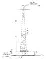
- FIG. 1is a system for irradiating tissue employing the fluorescent device of the present invention
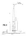
- FIG. 2is a cross-sectional view of a first embodiment of the fluorescent device
- FIG. 3depicts a fragmentary view of an exemplary reflective surface utilized in the fluorescent device
- FIG. 4is a cross-sectional view of a second embodiment of the fluorescent device
- FIG. 5depicts absorption and emission spectra of a representative fluorescent dye utilized in the fluorescent device
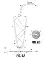
- FIG. 6( a )is a cross-sectional view of a third embodiment of the fluorescent device.
- FIG. 6( b )is a top plan view of an entrance face of the third embodiment.
- System 100generally comprises a pump radiation source 106 configured to generate pump radiation and supply the pump radiation to device 104 .
- pump radiation source 106Various light-emitting devices may be employed for pump radiation source 106 including, without limitation, a frequency-doubled neodymium-doped solid-state laser, an arc lamp or a flashlamp.
- pump radiation source 106generates and supplies pulsed radiation having a wavelength of 532 nanometers and a pulse duration of between 0 . 1 and 500 milliseconds.
- pump radiation source 106may generate CW or quasi-CW radiation.
- Pump radiation source 106is optically coupled to device 104 by optical fiber 108 , which delivers the pump radiation to a fluorescent element (not shown in FIG. 1 ) held within a housing 110 of device 104 .
- Optical fiber 108is flexible and thereby allows device 104 to be freely positioned relative to pump radiation source 106 .
- an articulated arm extending between pump radiation source 106 and device 104may be utilized for optical coupling in place of optical fiber 108 .
- pump radiation source 106may be integrated within housing 110 of device 104 , obviating the need for optical fiber 108 or equivalent means of delivering the pump radiation.
- System 100may optionally include a coolant recirculation system 112 for removing heat from a window 116 of device 104 .
- Window 116is fabricated from an optically transparent material and has a distal face 118 which is held in thermal contact with tissue target 102 during operation of system 100 .
- cooling of window 116beneficially reduces damage to non-targeted tissue and resultant scarring.
- Coolant recirculation system 112will conventionally comprise heat exchanger-based or evaporative chiller for removing heat from a liquid coolant (which may consist of water or a water/glycol mix) and a pump for delivering the chilled coolant to thermally conductive tubing contacting surfaces of window 116 .
- Other well-known techniques for cooling tissue target 102may be substituted for or used in conjunction with coolant recirculation system 112 .
- FIG. 2shows a cross-sectional view of device 104 .
- Device 104includes housing 110 in which is disposed a fluorescent element 202 .
- a redirector 204which operates to redirect radiation emitted by fluorescent element 202 toward tissue target 102 , includes a conically or frustro-conically shaped diffuse reflector 206 surrounding a cavity 208 .
- One end of housing 110is adapted to admit a corresponding end of optical fiber 108 , which delivers the pump radiation from pump radiation source 106 . Radiation leaving optical fiber 108 is thereafter directed through cavity 208 onto fluorescent element 202 .
- Fluorescent element 202may be fabricated from any one of a number of materials having fluorescent properties.
- the fluorescent element materialmay be selected to provide desired spectral characteristics of the emitted fluorescent light.
- fluorescent element 202is fabricated from a solid material consisting of a fluorescent dye compound (also known as a fluorochrome), such as Rhodamine 6G dispersed in a polymeric matrix, such as polyvinyl toluene (PVT) or polymethyl methacrylate (PMMA, commonly known as Plexiglas).
- a fluorescent dye compoundalso known as a fluorochrome
- Rhodamine 6Gdispersed in a polymeric matrix, such as polyvinyl toluene (PVT) or polymethyl methacrylate (PMMA, commonly known as Plexiglas).
- PVTpolyvinyl toluene
- PMMApolymethyl methacrylate
- fluorescent element 202Other materials which may be used to fabricate fluorescent element 202 include, without limitation, a laser dye dispersed in the interstitial voids of porous glass (also known as “thirsty glass”) or unconsolidated Vicor, phosphors, and laser crystals such as ruby.
- fluorescent element 202may comprise a static or recirculating encapsulated laser dye solution.
- fluorescent element 202may be constructed in a disk-like shape sized to be received within one end of housing 110 of device 104 , although other geometries and configurations may be utilized without departing from the scope of the invention.
- Fluorescent element 202is positioned to receive incident thereon the pump radiation delivered via optical fiber 108 At least a portion of the pump radiation is absorbed by fluorochromes (dye solution molecules) within fluorescent element 202 . Absorption of the pump radiation results in excitation of the fluorochromes (i.e., boosting of an electron from a ground to an excited state).
- Excitation of fluorochromescauses fluorescent element 202 to emit radiation, the emitted radiation having substantially different spectral characteristics from those of the absorbed (pump radiation). Emission and absorption spectra of a representative fluorochrome are depicted in FIG. 5 and discussed below.
- fluorescent element 202will emit radiation in all directions, and that in the absence of structures for redirecting radiation emitted by fluorescent element 202 in a non-preferred direction (i.e., away from tissue target 102 ), a substantial portion of the emitted radiation would be wasted.
- Device 104is therefore provided with redirector 204 for redirecting toward tissue target 102 radiation emitted by fluorescent element 202 in a non-preferred direction such that substantially all of the radiation emitted by fluorescent element 202 reaches tissue target 102 .
- redirector 204comprises an elongated frustro-conically shaped diffuse reflector 206 surrounding cavity 208 .
- the walls of reflector 206are relatively widely spaced proximal to fluorescent element 202 and become progressively narrower in the direction extending away from fluorescent element 202 .
- Radiation emitted by fluorescent element 202 in a non-preferred direction, as represented by ray 210enters redirector 206 and undergoes multiple reflections from the walls of reflector 206 in a random-walk fashion.
- Ray 210is eventually oriented such that it travels through cavity 208 in a direction substantially parallel to the central longitudinal axis of redirector 206 and subsequently passes through fluorescent element 202 and window 116 onto tissue target 102 .
- redirector 206may serve the additional function of collecting and redirecting toward tissue target 102 fluorescent radiation which is reflected by tissue target 102 .
- redirector 206may be constructed in other shapes (e.g., hemispherical), and hence the invention should not be construed as being limited to a conically- or frustro-conically shaped redirector.
- Window 116may be formed from glass, sapphire, or other suitable material which is substantially transparent in the wavelengths of the radiation emitted by fluorescent element 202 . Window 116 terminates in a distal face 118 which is maintained in contact with tissue target 102 during operation of system 100 . It has been found that undesirable collateral thermal damage caused to non-targeted tissue during procedures such as selective photothermolysis may be eliminated or substantially reduced by cooling the irradiated tissue (for a discussion of this benefit, reference may be made to U.S. Pat. No. 5,057,104 to Chess, entitled “Method and Apparatus for Treating Cutaneous Vascular Lesions”).
- window 116may be provided with thermally conductive tubing 216 , arranged about the periphery of window 116 , and through which is circulated chilled coolant supplied by coolant recirculation system 112 .
- Tubing 216may be held in good thermal contact with window 116 by means of an appropriate adhesive. Because glass or other optically transparent materials used to form window 116 typically have high thermal conductivities, cooling of window 116 effective cools tissue target 102 via conduction. Cooling of tissue target 102 may be optimized by applying a thermally conductive gel to tissue target 102 prior to bringing window 116 in contact therewith. Other techniques for cooling tissue target 102 are well known in the art and may be substituted for or used in conjunction with the technique described above.
- FIG. 3is a fragmentary view of a portion of a wall of reflector 206 .
- Reflector 206may be adapted with surface irregularities or protrusions 302 which effectively scatter light rays incident thereon, thus producing the random-walk behavior discussed above and depicted in FIG. 2 .
- Various shapes and sizes of surface irregularitiesmay be used to cause scattering.
- Reflector 206may comprise a reflective coating deposited on a supporting substrate, or alternatively be directly machined from a block of metal or other reflective material.
- FIG. 4depicts a second embodiment of a device 400 for irradiating tissue 102 .
- the device housinghas been omitted in FIG. 4 for the purpose of clarity.
- Device 400is provided with a fluorescent element 402 and window 404 of similar description to fluorescent element 202 and window 116 of the FIG. 2 embodiment.
- Redirector 406consists essentially of a mirror 408 having a coating 410 which selectively reflects wavelengths corresponding to the radiation emitted by fluorescent element 402 while being substantially transparent to wavelengths corresponding to the pump radiation.
- Coating 410may conventionally comprise a plurality of dielectric layers, the number, thicknesses, and composition of dielectric layers being chosen to produce the desired selective reflectance behavior.
- window 404may be provided with cooling means as discussed above in connection with FIG. 2 .
- FIG. 5depicts absorption and emission spectra of a representative fluorochrome (rhodamine 6G) which may be used in fluorescent element 202 or 402 . It can be seen that the absorption spectrum exhibits a peak at approximately 530 nanometers, while the emission or fluorescence spectrum peaks at approximately 560 nanometers. The difference between the peaks of the absorption and emission spectra, called the Stokes shift, varies among different fluorochromes. A clinician may therefore match the emission spectra to the absorption characteristics of target tissue 102 by selecting a device having a fluorescent element which produces the desired Stokes shift.
- rhodamine 6Grepresentative fluorochrome
- FIG. 6( a )is a cross-sectional view of a device 600 for irradiating tissue 102 according to a third embodiment of the invention.
- Device 600is provided with a fluorescent element 602 and window 604 of similar description to fluorescent element 202 and window 116 of the FIG. 2 embodiment.
- Redirector 606comprises a waveguide 608 having a reflective entrance face 610 and reflective walls 612 extending from entrance face 610 to fluorescent element 602 .
- the core of waveguide 608may be fabricated from glass, sapphire or other suitable high refraction index material. Referring to FIG.
- entrance face 610includes a central aperture 614 through which pump radiation from radiation source 106 is admitted into waveguide 608 .
- Central aperture 614is configured to be substantially transparent in the wavelength(s) of the pump radiation.
- Device 600may include a divergent lens or similar element 616 positioned between the end of optical fiber 108 and aperture 614 to distribute the radiation emitted by fiber 108 over fluorescent element 602 .
- Entrance face 610has an outer annular region 618 which is coated with a dielectric or metallic reflective coating to redirect toward tissue 102 radiation emitted by fluorescent element 602 , as shown in FIG. 6( a ).
- the area of aperture 614is preferably a small fraction of the area of outer region 618 .
- Walls 612may also be provided with a dielectric or metallic reflective coating to redirect emitted radiation. However, in a preferred embodiment, walls 612 comprise a boundary between the core of waveguide 608 and a cladding 620 (depicted in phantom).
- Cladding 620is constructed from a material, such as Teflon, having an index of refraction substantially lower than the index of refraction of the waveguide 608 core, which causes the emitted light to undergo total internal reflection at the boundary or walls 612 . Radiation emitted by fluorescent element 602 in a non-preferred direction is thereby redirected toward tissue 102 .
- waveguide 608is depicted as having a downwardly tapering duct shape, it is not to be construed as limited thereto and may instead be constructed, for example, in a conical or cylindrical shape. Further, although waveguide 608 is shown as being circular in cross-section, polygonal and other cross-sectional shapes may be substituted.
- fluorescent devices of the foregoing descriptionmay be utilized for numerous therapeutic applications.
- therapies for which the devices may be advantageously employedinclude (without limitation) photothermolysis of vascular and pigmented lesions, tattoo removal, hair removal, and photodynamic therapy (PDT) for treatment of tumors.
- PDTphotodynamic therapy
Landscapes
- Health & Medical Sciences (AREA)
- Physics & Mathematics (AREA)
- Surgery (AREA)
- Life Sciences & Earth Sciences (AREA)
- Optics & Photonics (AREA)
- Engineering & Computer Science (AREA)
- Otolaryngology (AREA)
- Nuclear Medicine, Radiotherapy & Molecular Imaging (AREA)
- Electromagnetism (AREA)
- Biomedical Technology (AREA)
- Heart & Thoracic Surgery (AREA)
- Medical Informatics (AREA)
- Molecular Biology (AREA)
- Animal Behavior & Ethology (AREA)
- General Health & Medical Sciences (AREA)
- Public Health (AREA)
- Veterinary Medicine (AREA)
- Laser Surgery Devices (AREA)
Abstract
Description
Claims (33)
Priority Applications (1)
| Application Number | Priority Date | Filing Date | Title |
|---|---|---|---|
| US09/589,675US7083610B1 (en) | 2000-06-07 | 2000-06-07 | Device for irradiating tissue |
Applications Claiming Priority (1)
| Application Number | Priority Date | Filing Date | Title |
|---|---|---|---|
| US09/589,675US7083610B1 (en) | 2000-06-07 | 2000-06-07 | Device for irradiating tissue |
Publications (1)
| Publication Number | Publication Date |
|---|---|
| US7083610B1true US7083610B1 (en) | 2006-08-01 |
Family
ID=36710479
Family Applications (1)
| Application Number | Title | Priority Date | Filing Date |
|---|---|---|---|
| US09/589,675Expired - LifetimeUS7083610B1 (en) | 2000-06-07 | 2000-06-07 | Device for irradiating tissue |
Country Status (1)
| Country | Link |
|---|---|
| US (1) | US7083610B1 (en) |
Cited By (40)
| Publication number | Priority date | Publication date | Assignee | Title |
|---|---|---|---|---|
| US20050063197A1 (en)* | 2003-08-07 | 2005-03-24 | Nightingale John L. | System and method utilizing guided fluorescence for high intensity applications |
| US20050080404A1 (en)* | 2002-08-26 | 2005-04-14 | Jones Jeffrey W. | Tapered fused waveguide for teeth whitening |
| US20050147137A1 (en)* | 2001-12-10 | 2005-07-07 | Inolase 2002 Ltd. | Eye safe dermatological phototherapy |
| US20050182461A1 (en)* | 2003-12-09 | 2005-08-18 | Medx Health Corp. | Shape-adaptable and spectral-selective distributed light sources using passive host medium |
| US20060009749A1 (en)* | 2004-02-19 | 2006-01-12 | Weckwerth Mark V | Efficient diffuse light source assembly and method |
| US20060015091A1 (en)* | 2002-11-28 | 2006-01-19 | Koninklijke Philips Electronics N.V. | Device for treating human skin by means of radiation |
| US20060030909A1 (en)* | 2002-12-16 | 2006-02-09 | Msq(M2) Ltd. | Device and method for treating skin |
| US20070189352A1 (en)* | 2006-02-14 | 2007-08-16 | Nichia Corporation | Light emitting device |
| US20070262274A1 (en)* | 2004-09-30 | 2007-11-15 | Elekta Ab | Radiotherapeutic Apparatus |
| US20070281322A1 (en)* | 2006-05-22 | 2007-12-06 | Lumencor, Inc. | Bioanalytical instrumentation using a light source subsystem |
| US20080262484A1 (en)* | 2007-04-23 | 2008-10-23 | Nlight Photonics Corporation | Motion-controlled laser surface treatment apparatus |
| US20090008573A1 (en)* | 2007-07-03 | 2009-01-08 | Conner Arlie R | Light emitting diode illumination system |
| WO2009018529A1 (en)* | 2007-08-02 | 2009-02-05 | Candela Corporation | Device and method for treatment of organic tissue |
| US20090182397A1 (en)* | 2008-01-16 | 2009-07-16 | Candela Corporation | Fluorescent handpiece |
| CN101803950A (en)* | 2010-03-18 | 2010-08-18 | 镇江步云电子有限公司 | Illuminable radiator of microwave remedial instrument |
| US20100324544A1 (en)* | 2006-10-23 | 2010-12-23 | Koninklijke Philips Electronics N.V. | Optical treatment system and an adjustment member therefor |
| US7898665B2 (en) | 2007-08-06 | 2011-03-01 | Lumencor, Inc. | Light emitting diode illumination system |
| US8149526B2 (en) | 2008-09-18 | 2012-04-03 | Photothera, Inc. | Single use lens assembly |
| EP2436332A1 (en)* | 2010-09-30 | 2012-04-04 | Braun GmbH | Light-based skin treatment device |
| US8242462B2 (en) | 2009-01-23 | 2012-08-14 | Lumencor, Inc. | Lighting design of high quality biomedical devices |
| US8389957B2 (en) | 2011-01-14 | 2013-03-05 | Lumencor, Inc. | System and method for metered dosage illumination in a bioanalysis or other system |
| US8465532B2 (en) | 2008-01-16 | 2013-06-18 | Morgan Lars Ake Gustavsson | Fluorescent handpiece |
| US8466436B2 (en) | 2011-01-14 | 2013-06-18 | Lumencor, Inc. | System and method for metered dosage illumination in a bioanalysis or other system |
| US8551104B2 (en) | 2003-02-25 | 2013-10-08 | Tria Beauty, Inc. | Self-contained, diode-laser-based dermatologic treatment apparatus |
| US20140155876A1 (en)* | 2003-02-25 | 2014-06-05 | Tria Beauty, Inc. | Self-contained, eye-safe hair-regrowth-inhibition apparatus and method |
| US8777935B2 (en) | 2004-02-25 | 2014-07-15 | Tria Beauty, Inc. | Optical sensor and method for identifying the presence of skin |
| US20140276354A1 (en)* | 2013-03-14 | 2014-09-18 | Klox Technologies Inc. | Biophotonic materials and uses thereof |
| US8967846B2 (en) | 2012-01-20 | 2015-03-03 | Lumencor, Inc. | Solid state continuous white light source |
| US9155905B2 (en) | 2008-01-16 | 2015-10-13 | Morgan Lars Ake Gustavsson | Fluorescent handpiece |
| US9217561B2 (en) | 2012-06-15 | 2015-12-22 | Lumencor, Inc. | Solid state light source for photocuring |
| US20160282572A1 (en)* | 2015-03-24 | 2016-09-29 | Samtec, Inc. | Optical block with textured surface |
| US9687671B2 (en) | 2008-04-25 | 2017-06-27 | Channel Investments, Llc | Optical sensor and method for identifying the presence of skin and the pigmentation of skin |
| WO2017189109A1 (en)* | 2016-04-26 | 2017-11-02 | Candela Corporation | Applicator for cooling skin during irradiation |
| US10188872B2 (en) | 2006-01-30 | 2019-01-29 | Pthera LLC | Light-emitting device and method for providing phototherapy to the brain |
| US10376455B2 (en) | 2012-04-20 | 2019-08-13 | Klox Technologies Inc. | Biophotonic compositions and methods for providing biophotonic treatment |
| US10695577B2 (en) | 2001-12-21 | 2020-06-30 | Photothera, Inc. | Device and method for providing phototherapy to the heart |
| US10758743B2 (en) | 2001-11-01 | 2020-09-01 | Pthera LLC | Method for providing phototherapy to the brain |
| US10772683B2 (en) | 2014-05-18 | 2020-09-15 | Eximo Medical Ltd. | System for tissue ablation using pulsed laser |
| US10881736B2 (en) | 2013-07-03 | 2021-01-05 | Klox Technologies Inc. | Biophotonic compositions comprising a chromophore and a gelling agent for treating wounds |
| US11116841B2 (en) | 2012-04-20 | 2021-09-14 | Klox Technologies Inc. | Biophotonic compositions, kits and methods |
Citations (27)
| Publication number | Priority date | Publication date | Assignee | Title |
|---|---|---|---|---|
| US4273109A (en)* | 1976-07-06 | 1981-06-16 | Cavitron Corporation | Fiber optic light delivery apparatus and medical instrument utilizing same |
| US4336809A (en)* | 1980-03-17 | 1982-06-29 | Burleigh Instruments, Inc. | Human and animal tissue photoradiation system and method |
| US4695697A (en)* | 1985-12-13 | 1987-09-22 | Gv Medical, Inc. | Fiber tip monitoring and protection assembly |
| US4764739A (en)* | 1981-10-13 | 1988-08-16 | The United States Of America As Represented By The Secretary Of The Navy | Light-induced unidirectional light switch |
| US4853528A (en)* | 1985-12-19 | 1989-08-01 | Hughes Aircraft Company | Self-aligning phase conjugate laser |
| US4852567A (en)* | 1988-01-21 | 1989-08-01 | C. R. Bard, Inc. | Laser tipped catheter |
| US4994059A (en)* | 1986-05-09 | 1991-02-19 | Gv Medical, Inc. | Laser catheter feedback system |
| US5405368A (en)* | 1992-10-20 | 1995-04-11 | Esc Inc. | Method and apparatus for therapeutic electromagnetic treatment |
| US5415655A (en)* | 1992-04-24 | 1995-05-16 | Surgical Laser Technologies, Inc. | Medical device including light energy emitting contact tip with means for raising temperature of the tip |
| US5425754A (en)* | 1993-03-08 | 1995-06-20 | Maxs Ag | Infrared radiation lamp apparatus having a cuvette positioned in its optical path and a method for using the same |
| US5720772A (en)* | 1992-10-20 | 1998-02-24 | Esc Medical Systems Ltd. | Method and apparatus for therapeutic electromagnetic treatment |
| US5735844A (en)* | 1995-02-01 | 1998-04-07 | The General Hospital Corporation | Hair removal using optical pulses |
| US5824023A (en) | 1995-10-12 | 1998-10-20 | The General Hospital Corporation | Radiation-delivery device |
| US5830208A (en)* | 1997-01-31 | 1998-11-03 | Laserlite, Llc | Peltier cooled apparatus and methods for dermatological treatment |
| US5885274A (en)* | 1997-06-24 | 1999-03-23 | New Star Lasers, Inc. | Filament lamp for dermatological treatment |
| US5928222A (en)* | 1982-08-06 | 1999-07-27 | Kleinerman; Marcos Y. | Fiber optic sensing techniques in laser medicine |
| US5961543A (en)* | 1995-11-08 | 1999-10-05 | Herbert Waldmann Gmbh & Co. | Method and apparatus for photodynamic irradiation |
| US5964749A (en)* | 1995-09-15 | 1999-10-12 | Esc Medical Systems Ltd. | Method and apparatus for skin rejuvenation and wrinkle smoothing |
| USRE36634E (en)* | 1991-12-12 | 2000-03-28 | Ghaffari; Shahriar | Optical system for treatment of vascular lesions |
| US6156030A (en)* | 1997-06-04 | 2000-12-05 | Y-Beam Technologies, Inc. | Method and apparatus for high precision variable rate material removal and modification |
| US6171302B1 (en)* | 1997-03-19 | 2001-01-09 | Gerard Talpalriu | Apparatus and method including a handpiece for synchronizing the pulsing of a light source |
| US6214034B1 (en)* | 1996-09-04 | 2001-04-10 | Radiancy, Inc. | Method of selective photothermolysis |
| US6235017B1 (en)* | 1997-03-11 | 2001-05-22 | Vitcon Projektconsult Gmbh | Device for ablation of material by means of laser radiation |
| US6254594B1 (en)* | 1999-07-30 | 2001-07-03 | Quadrivium, Llc | Disposable light source for photothermal treatment of human tissue |
| US6270492B1 (en)* | 1994-09-09 | 2001-08-07 | Cardiofocus, Inc. | Phototherapeutic apparatus with diffusive tip assembly |
| US6280438B1 (en)* | 1992-10-20 | 2001-08-28 | Esc Medical Systems Ltd. | Method and apparatus for electromagnetic treatment of the skin, including hair depilation |
| US6835202B2 (en)* | 1998-07-09 | 2004-12-28 | Curelight Ltd. | Apparatus and method for high energy photodynamic therapy of acne vulgaris and seborrhea |
- 2000
- 2000-06-07USUS09/589,675patent/US7083610B1/ennot_activeExpired - Lifetime
Patent Citations (28)
| Publication number | Priority date | Publication date | Assignee | Title |
|---|---|---|---|---|
| US4273109A (en)* | 1976-07-06 | 1981-06-16 | Cavitron Corporation | Fiber optic light delivery apparatus and medical instrument utilizing same |
| US4336809A (en)* | 1980-03-17 | 1982-06-29 | Burleigh Instruments, Inc. | Human and animal tissue photoradiation system and method |
| US4764739A (en)* | 1981-10-13 | 1988-08-16 | The United States Of America As Represented By The Secretary Of The Navy | Light-induced unidirectional light switch |
| US5928222A (en)* | 1982-08-06 | 1999-07-27 | Kleinerman; Marcos Y. | Fiber optic sensing techniques in laser medicine |
| US4695697A (en)* | 1985-12-13 | 1987-09-22 | Gv Medical, Inc. | Fiber tip monitoring and protection assembly |
| US4853528A (en)* | 1985-12-19 | 1989-08-01 | Hughes Aircraft Company | Self-aligning phase conjugate laser |
| US4994059A (en)* | 1986-05-09 | 1991-02-19 | Gv Medical, Inc. | Laser catheter feedback system |
| US4852567A (en)* | 1988-01-21 | 1989-08-01 | C. R. Bard, Inc. | Laser tipped catheter |
| USRE36634E (en)* | 1991-12-12 | 2000-03-28 | Ghaffari; Shahriar | Optical system for treatment of vascular lesions |
| US5415655A (en)* | 1992-04-24 | 1995-05-16 | Surgical Laser Technologies, Inc. | Medical device including light energy emitting contact tip with means for raising temperature of the tip |
| US5720772A (en)* | 1992-10-20 | 1998-02-24 | Esc Medical Systems Ltd. | Method and apparatus for therapeutic electromagnetic treatment |
| US6514243B1 (en)* | 1992-10-20 | 2003-02-04 | Lumenis Ltd. | Method and apparatus for electromagnetic treatment of the skin, including hair depilation |
| US6280438B1 (en)* | 1992-10-20 | 2001-08-28 | Esc Medical Systems Ltd. | Method and apparatus for electromagnetic treatment of the skin, including hair depilation |
| US5405368A (en)* | 1992-10-20 | 1995-04-11 | Esc Inc. | Method and apparatus for therapeutic electromagnetic treatment |
| US5425754A (en)* | 1993-03-08 | 1995-06-20 | Maxs Ag | Infrared radiation lamp apparatus having a cuvette positioned in its optical path and a method for using the same |
| US6270492B1 (en)* | 1994-09-09 | 2001-08-07 | Cardiofocus, Inc. | Phototherapeutic apparatus with diffusive tip assembly |
| US5735844A (en)* | 1995-02-01 | 1998-04-07 | The General Hospital Corporation | Hair removal using optical pulses |
| US5964749A (en)* | 1995-09-15 | 1999-10-12 | Esc Medical Systems Ltd. | Method and apparatus for skin rejuvenation and wrinkle smoothing |
| US5824023A (en) | 1995-10-12 | 1998-10-20 | The General Hospital Corporation | Radiation-delivery device |
| US5961543A (en)* | 1995-11-08 | 1999-10-05 | Herbert Waldmann Gmbh & Co. | Method and apparatus for photodynamic irradiation |
| US6214034B1 (en)* | 1996-09-04 | 2001-04-10 | Radiancy, Inc. | Method of selective photothermolysis |
| US5830208A (en)* | 1997-01-31 | 1998-11-03 | Laserlite, Llc | Peltier cooled apparatus and methods for dermatological treatment |
| US6235017B1 (en)* | 1997-03-11 | 2001-05-22 | Vitcon Projektconsult Gmbh | Device for ablation of material by means of laser radiation |
| US6171302B1 (en)* | 1997-03-19 | 2001-01-09 | Gerard Talpalriu | Apparatus and method including a handpiece for synchronizing the pulsing of a light source |
| US6156030A (en)* | 1997-06-04 | 2000-12-05 | Y-Beam Technologies, Inc. | Method and apparatus for high precision variable rate material removal and modification |
| US5885274A (en)* | 1997-06-24 | 1999-03-23 | New Star Lasers, Inc. | Filament lamp for dermatological treatment |
| US6835202B2 (en)* | 1998-07-09 | 2004-12-28 | Curelight Ltd. | Apparatus and method for high energy photodynamic therapy of acne vulgaris and seborrhea |
| US6254594B1 (en)* | 1999-07-30 | 2001-07-03 | Quadrivium, Llc | Disposable light source for photothermal treatment of human tissue |
Non-Patent Citations (1)
| Title |
|---|
| "Aura. Greater Versatility, Reliability and Value" Product information available at: www.laserscope.com/professionals/aesthetics/aura.pdf. |
Cited By (106)
| Publication number | Priority date | Publication date | Assignee | Title |
|---|---|---|---|---|
| US20120015319A1 (en)* | 2001-08-24 | 2012-01-19 | Biolase Technology, Inc. | Tapered fused waveguide for teeth whitening |
| US8439904B2 (en)* | 2001-08-24 | 2013-05-14 | Biolase, Inc. | Tapered fused waveguide for teeth whitening |
| US10758743B2 (en) | 2001-11-01 | 2020-09-01 | Pthera LLC | Method for providing phototherapy to the brain |
| US20100246619A9 (en)* | 2001-12-10 | 2010-09-30 | Inolase 2002 Ltd. | Eye safe dermatological phototherapy |
| US7935139B2 (en) | 2001-12-10 | 2011-05-03 | Candela Corporation | Eye safe dermatological phototherapy |
| US20050147137A1 (en)* | 2001-12-10 | 2005-07-07 | Inolase 2002 Ltd. | Eye safe dermatological phototherapy |
| US10695577B2 (en) | 2001-12-21 | 2020-06-30 | Photothera, Inc. | Device and method for providing phototherapy to the heart |
| US20050080404A1 (en)* | 2002-08-26 | 2005-04-14 | Jones Jeffrey W. | Tapered fused waveguide for teeth whitening |
| US7384419B2 (en)* | 2002-08-26 | 2008-06-10 | Biolase Technology, Inc. | Tapered fused waveguide for delivering treatment electromagnetic radiation toward a target surfaced |
| US20060015091A1 (en)* | 2002-11-28 | 2006-01-19 | Koninklijke Philips Electronics N.V. | Device for treating human skin by means of radiation |
| US7517344B2 (en)* | 2002-11-28 | 2009-04-14 | Koninklijke Philips Electronics N.V. | Device for treating human skin by means of radiation |
| US20060030909A1 (en)* | 2002-12-16 | 2006-02-09 | Msq(M2) Ltd. | Device and method for treating skin |
| US8551104B2 (en) | 2003-02-25 | 2013-10-08 | Tria Beauty, Inc. | Self-contained, diode-laser-based dermatologic treatment apparatus |
| US20140155876A1 (en)* | 2003-02-25 | 2014-06-05 | Tria Beauty, Inc. | Self-contained, eye-safe hair-regrowth-inhibition apparatus and method |
| US10342618B2 (en)* | 2003-02-25 | 2019-07-09 | Channel Investments, Llc | Self-contained, eye-safe hair-regrowth-inhibition apparatus and method |
| US10342617B2 (en) | 2003-02-25 | 2019-07-09 | Channel Investments, Llc | Phototherapy device thermal control apparatus and method |
| US7208007B2 (en) | 2003-08-07 | 2007-04-24 | Cutera, Inc. | System and method utilizing guided fluorescence for high intensity applications |
| US20050063197A1 (en)* | 2003-08-07 | 2005-03-24 | Nightingale John L. | System and method utilizing guided fluorescence for high intensity applications |
| US7998181B2 (en) | 2003-08-07 | 2011-08-16 | Cutera, Inc. | System and method utilizing guided fluorescence for high intensity applications |
| US20060282137A1 (en)* | 2003-08-07 | 2006-12-14 | Nightingale John L | System and method utilizing guided fluorescence for high intensity applications |
| US20080287941A1 (en)* | 2003-11-10 | 2008-11-20 | Jones Jeffrey W | Tapered fused waveguide for teeth whitening |
| US7998136B2 (en)* | 2003-11-10 | 2011-08-16 | Biolase Technology, Inc. | Medical radiation device with a tapered fused waveguide |
| US7878203B2 (en)* | 2003-12-09 | 2011-02-01 | Medx Health Corp. | Phototherapeutic treatment method using a passive host medium containing nanoparticles |
| US20050182461A1 (en)* | 2003-12-09 | 2005-08-18 | Medx Health Corp. | Shape-adaptable and spectral-selective distributed light sources using passive host medium |
| US20060009749A1 (en)* | 2004-02-19 | 2006-01-12 | Weckwerth Mark V | Efficient diffuse light source assembly and method |
| US8777935B2 (en) | 2004-02-25 | 2014-07-15 | Tria Beauty, Inc. | Optical sensor and method for identifying the presence of skin |
| US7763865B2 (en)* | 2004-09-30 | 2010-07-27 | Elekta Ab | Radiotherapeutic apparatus |
| US20070262274A1 (en)* | 2004-09-30 | 2007-11-15 | Elekta Ab | Radiotherapeutic Apparatus |
| US11179572B2 (en) | 2006-01-30 | 2021-11-23 | Pthera LLC | Light-emitting device and method for providing phototherapy to the brain |
| US10188872B2 (en) | 2006-01-30 | 2019-01-29 | Pthera LLC | Light-emitting device and method for providing phototherapy to the brain |
| US12303709B2 (en) | 2006-01-30 | 2025-05-20 | Pthera, Llc | Light-emitting device and method for providing phototherapy to the brain |
| US20070189352A1 (en)* | 2006-02-14 | 2007-08-16 | Nichia Corporation | Light emitting device |
| US8908740B2 (en)* | 2006-02-14 | 2014-12-09 | Nichia Corporation | Light emitting device |
| US8728399B2 (en) | 2006-05-22 | 2014-05-20 | Lumencor, Inc. | Bioanalytical instrumentation using a light source subsystem |
| US9063007B2 (en) | 2006-05-22 | 2015-06-23 | Lumencor, Inc. | Bioanalytical instrumentation using a light source subsystem |
| US8673218B2 (en) | 2006-05-22 | 2014-03-18 | Lumencor, Inc. | Bioanalytical instrumentation using a light source subsystem |
| US20070281322A1 (en)* | 2006-05-22 | 2007-12-06 | Lumencor, Inc. | Bioanalytical instrumentation using a light source subsystem |
| US7846391B2 (en) | 2006-05-22 | 2010-12-07 | Lumencor, Inc. | Bioanalytical instrumentation using a light source subsystem |
| US20100324544A1 (en)* | 2006-10-23 | 2010-12-23 | Koninklijke Philips Electronics N.V. | Optical treatment system and an adjustment member therefor |
| US20080262484A1 (en)* | 2007-04-23 | 2008-10-23 | Nlight Photonics Corporation | Motion-controlled laser surface treatment apparatus |
| US7709811B2 (en) | 2007-07-03 | 2010-05-04 | Conner Arlie R | Light emitting diode illumination system |
| US20090008573A1 (en)* | 2007-07-03 | 2009-01-08 | Conner Arlie R | Light emitting diode illumination system |
| WO2009018529A1 (en)* | 2007-08-02 | 2009-02-05 | Candela Corporation | Device and method for treatment of organic tissue |
| US20090036953A1 (en)* | 2007-08-02 | 2009-02-05 | Morgan Lars Ake Gustavsson | Device and method for treatment of organic tissue |
| US9849304B2 (en)* | 2007-08-02 | 2017-12-26 | Gustavsson Nevada Holding Llc | Device and method for treatment of organic tissue |
| US8525999B2 (en) | 2007-08-06 | 2013-09-03 | Lumencor, Inc. | Light emitting diode illumination system |
| US8279442B2 (en) | 2007-08-06 | 2012-10-02 | Lumencor, Inc. | Light emitting diode illumination system |
| US7898665B2 (en) | 2007-08-06 | 2011-03-01 | Lumencor, Inc. | Light emitting diode illumination system |
| US8098375B2 (en) | 2007-08-06 | 2012-01-17 | Lumencor, Inc. | Light emitting diode illumination system |
| US8493564B2 (en) | 2007-08-06 | 2013-07-23 | Lumencor, Inc. | Light emitting diode illumination system |
| US9574722B2 (en) | 2007-08-06 | 2017-02-21 | Lumencor, Inc. | Light emitting diode illumination system |
| US9395055B2 (en) | 2007-08-06 | 2016-07-19 | Lumencor, Inc. | Light emitting diode illumination system |
| US9068703B2 (en) | 2007-08-06 | 2015-06-30 | Lumencor, Inc. | Light emitting diode illumination system |
| US9062832B2 (en) | 2007-08-06 | 2015-06-23 | Lumencor, Inc. | Light emitting diode illumination system |
| US8625097B2 (en) | 2007-08-06 | 2014-01-07 | Lumencor, Inc. | Light emitting diode illumination system |
| US8629982B2 (en) | 2007-08-06 | 2014-01-14 | Lumencor, Inc. | Light emitting diode illumination system |
| US7955367B2 (en)* | 2008-01-16 | 2011-06-07 | Morgan Gustavsson | Fluorescent handpiece |
| US9452298B2 (en) | 2008-01-16 | 2016-09-27 | Morgan Gustavsson | Fluorescent handpiece |
| US8287578B2 (en) | 2008-01-16 | 2012-10-16 | Morgan Lars Ake Gustavsson | Fluorescent handpiece |
| US8105369B2 (en) | 2008-01-16 | 2012-01-31 | Morgan Gustavsson | Fluorescent handpiece |
| US8518093B2 (en) | 2008-01-16 | 2013-08-27 | Morgan Lars Ake Gustavsson | Fluorescent handpiece |
| US20090182397A1 (en)* | 2008-01-16 | 2009-07-16 | Candela Corporation | Fluorescent handpiece |
| US9539440B2 (en) | 2008-01-16 | 2017-01-10 | Gustavsson Nevada Holding Llc | Fluorescent handpiece |
| US8945105B2 (en) | 2008-01-16 | 2015-02-03 | Morgan Gustavsson | Fluorescent handpiece |
| US20110238047A1 (en)* | 2008-01-16 | 2011-09-29 | Morgan Lars Ake Gustavsson | Fluorescent handpiece |
| US8465532B2 (en) | 2008-01-16 | 2013-06-18 | Morgan Lars Ake Gustavsson | Fluorescent handpiece |
| US8579951B2 (en) | 2008-01-16 | 2013-11-12 | Morgan Gustavsson | Fluorescent handpiece |
| US8419781B2 (en) | 2008-01-16 | 2013-04-16 | Morgan Gustavsson | Fluorescent handpiece |
| US9192779B2 (en) | 2008-01-16 | 2015-11-24 | Morgan Lars Ake Gustavsson | Fluorescent handpiece |
| US9155905B2 (en) | 2008-01-16 | 2015-10-13 | Morgan Lars Ake Gustavsson | Fluorescent handpiece |
| US9687671B2 (en) | 2008-04-25 | 2017-06-27 | Channel Investments, Llc | Optical sensor and method for identifying the presence of skin and the pigmentation of skin |
| US8149526B2 (en) | 2008-09-18 | 2012-04-03 | Photothera, Inc. | Single use lens assembly |
| US10071259B2 (en) | 2008-09-18 | 2018-09-11 | Pthera, Llc | Optical assembly |
| US8309940B2 (en) | 2009-01-23 | 2012-11-13 | Lumencor, Inc. | Lighting design of high quality biomedical devices |
| US8698101B2 (en) | 2009-01-23 | 2014-04-15 | Lumencor, Inc. | Lighting design of high quality biomedical devices |
| US8242462B2 (en) | 2009-01-23 | 2012-08-14 | Lumencor, Inc. | Lighting design of high quality biomedical devices |
| US8258487B1 (en) | 2009-01-23 | 2012-09-04 | Lumencor, Inc. | Lighting design of high quality biomedical devices |
| US8263949B2 (en) | 2009-01-23 | 2012-09-11 | Lumencor, Inc. | Lighting design of high quality biomedical devices |
| CN101803950A (en)* | 2010-03-18 | 2010-08-18 | 镇江步云电子有限公司 | Illuminable radiator of microwave remedial instrument |
| EP2436332A1 (en)* | 2010-09-30 | 2012-04-04 | Braun GmbH | Light-based skin treatment device |
| US9335266B2 (en) | 2011-01-14 | 2016-05-10 | Lumencor, Inc. | System and method for controlled intensity illumination in a bioanalysis or other system |
| US9658160B2 (en) | 2011-01-14 | 2017-05-23 | Lumencor, Inc. | System and method for controlled intensity illumination in a bioanalysis or other system |
| US8466436B2 (en) | 2011-01-14 | 2013-06-18 | Lumencor, Inc. | System and method for metered dosage illumination in a bioanalysis or other system |
| US8389957B2 (en) | 2011-01-14 | 2013-03-05 | Lumencor, Inc. | System and method for metered dosage illumination in a bioanalysis or other system |
| US9103528B2 (en) | 2012-01-20 | 2015-08-11 | Lumencor, Inc | Solid state continuous white light source |
| US9642515B2 (en) | 2012-01-20 | 2017-05-09 | Lumencor, Inc. | Solid state continuous white light source |
| US8967846B2 (en) | 2012-01-20 | 2015-03-03 | Lumencor, Inc. | Solid state continuous white light source |
| US8967811B2 (en) | 2012-01-20 | 2015-03-03 | Lumencor, Inc. | Solid state continuous white light source |
| US11331257B2 (en) | 2012-04-20 | 2022-05-17 | Klox Technologies Inc. | Biophotonic compositions and methods for providing biophotonic treatment |
| US11116841B2 (en) | 2012-04-20 | 2021-09-14 | Klox Technologies Inc. | Biophotonic compositions, kits and methods |
| US10376455B2 (en) | 2012-04-20 | 2019-08-13 | Klox Technologies Inc. | Biophotonic compositions and methods for providing biophotonic treatment |
| US11723854B2 (en) | 2012-04-20 | 2023-08-15 | Fle International S.R.L. | Biophotonic compositions and methods for providing biophotonic treatment |
| US9217561B2 (en) | 2012-06-15 | 2015-12-22 | Lumencor, Inc. | Solid state light source for photocuring |
| US20140276354A1 (en)* | 2013-03-14 | 2014-09-18 | Klox Technologies Inc. | Biophotonic materials and uses thereof |
| US10130706B2 (en) | 2013-03-14 | 2018-11-20 | Klox Technologies Inc. | Biophotonic materials and uses thereof |
| US11324823B2 (en) | 2013-03-14 | 2022-05-10 | Klox Technologies Inc. | Biophotonic materials and uses thereof |
| US10881736B2 (en) | 2013-07-03 | 2021-01-05 | Klox Technologies Inc. | Biophotonic compositions comprising a chromophore and a gelling agent for treating wounds |
| US10772683B2 (en) | 2014-05-18 | 2020-09-15 | Eximo Medical Ltd. | System for tissue ablation using pulsed laser |
| US10792103B2 (en) | 2014-05-18 | 2020-10-06 | Eximo Medical Ltd. | System for tissue ablation using pulsed laser |
| US10884198B2 (en)* | 2015-03-24 | 2021-01-05 | Samtec, Inc | Optical block with textured surface |
| US11693194B2 (en)* | 2015-03-24 | 2023-07-04 | Samtec, Inc. | Optical block with textured surface |
| US20230221504A1 (en)* | 2015-03-24 | 2023-07-13 | Samtec, Inc. | Optical block with textured surface |
| US20160282572A1 (en)* | 2015-03-24 | 2016-09-29 | Samtec, Inc. | Optical block with textured surface |
| US12055771B2 (en)* | 2015-03-24 | 2024-08-06 | Samtec, Inc. | Optical block with textured surface |
| WO2017189109A1 (en)* | 2016-04-26 | 2017-11-02 | Candela Corporation | Applicator for cooling skin during irradiation |
| CN109310470A (en)* | 2016-04-26 | 2019-02-05 | 康代拉公司 | Applicator for skin cooling during irradiation |
Similar Documents
| Publication | Publication Date | Title |
|---|---|---|
| US7083610B1 (en) | Device for irradiating tissue | |
| US5643334A (en) | Method and apparatus for the diagnostic and composite pulsed heating and photodynamic therapy treatment | |
| US7998181B2 (en) | System and method utilizing guided fluorescence for high intensity applications | |
| US4852567A (en) | Laser tipped catheter | |
| US5586981A (en) | Treatment of cutaneous vascular and pigmented lesions | |
| US6554825B1 (en) | Variable pulse duration, adjustable wavelength medical laser system | |
| JP4691547B2 (en) | Alexandrite laser system for treating dermatological specimens | |
| KR940003440B1 (en) | Long pulse tunable dye laser | |
| US6461866B1 (en) | In vitro photodynamic therapy using non laser light | |
| US5620478A (en) | Method and apparatus for therapeutic electromagnetic treatment | |
| US5626631A (en) | Method and apparatus for therapeutic electromagnetic treatment | |
| US6613040B2 (en) | Twin light laser | |
| US4336809A (en) | Human and animal tissue photoradiation system and method | |
| JP2006334438A (en) | Apparatus and method for photocosmetic and photodermatological treatment | |
| US7241291B2 (en) | Method and system for skin treatment using light energy and skin deformation | |
| JP2003126277A (en) | Device for performing dermatological treatment and head used in the device | |
| JP2004514479A (en) | Laser penetration depth control device | |
| JPH0999107A (en) | Method and apparatus for electromagnetic therapy | |
| CA2279346A1 (en) | Peltier cooled apparatus and methods for dermatological treatment | |
| JP2003530686A (en) | Multi-pulse dye laser | |
| CN112438799B (en) | Tips for Multi-Beam Tissue Therapy | |
| US20050251231A1 (en) | Treatment method and apparatus for basal cell carcinoma | |
| HK40046901A (en) | Tip for multiple beam tissue therapy | |
| JPH10135539A (en) | Laser device | |
| Miller | Edward Victor Ross |
Legal Events
| Date | Code | Title | Description |
|---|---|---|---|
| AS | Assignment | Owner name:LASERSCOPE, A CALIFORNIA CORPORATION, CALIFORNIA Free format text:ASSIGNMENT OF ASSIGNORS INTEREST;ASSIGNORS:MURRAY, STEVEN C.;DAVENPORT, SCOTT A.;REEL/FRAME:010858/0791 Effective date:20000605 | |
| STCF | Information on status: patent grant | Free format text:PATENTED CASE | |
| AS | Assignment | Owner name:CIT HEALTHCARE LLC, NEW YORK Free format text:SECURITY AGREEMENT;ASSIGNOR:LASERSCOPE;REEL/FRAME:018132/0682 Effective date:20060720 | |
| FEPP | Fee payment procedure | Free format text:PAT HOLDER NO LONGER CLAIMS SMALL ENTITY STATUS, ENTITY STATUS SET TO UNDISCOUNTED (ORIGINAL EVENT CODE: STOL); ENTITY STATUS OF PATENT OWNER: LARGE ENTITY Free format text:PAYOR NUMBER ASSIGNED (ORIGINAL EVENT CODE: ASPN); ENTITY STATUS OF PATENT OWNER: LARGE ENTITY | |
| FPAY | Fee payment | Year of fee payment:4 | |
| AS | Assignment | Owner name:LASERSCOPE, MINNESOTA Free format text:RELEASE BY SECURED PARTY;ASSIGNOR:CIT HEALTHCARE LLC;REEL/FRAME:026142/0093 Effective date:20110412 | |
| AS | Assignment | Owner name:MORGAN STANLEY SENIOR FUNDING, INC., AS ADMINISTRA Free format text:SECURITY AGREEMENT;ASSIGNOR:LASERSCOPE;REEL/FRAME:026628/0340 Effective date:20110617 | |
| FPAY | Fee payment | Year of fee payment:8 | |
| AS | Assignment | Owner name:LASERSCOPE, CALIFORNIA Free format text:RELEASE OF PATENT SECURITY INTEREST;ASSIGNOR:MORGAN STANLEY SENIOR FUNDING, INC., AS ADMINISTRATIVE AGENT;REEL/FRAME:032380/0324 Effective date:20140228 Owner name:AMS RESEARCH CORPORATION, MINNESOTA Free format text:RELEASE OF PATENT SECURITY INTEREST;ASSIGNOR:MORGAN STANLEY SENIOR FUNDING, INC., AS ADMINISTRATIVE AGENT;REEL/FRAME:032380/0053 Effective date:20140228 | |
| AS | Assignment | Owner name:DEUTSCHE BANK AG NEW YORK BRANCH, AS COLLATERAL AGENT, NEW YORK Free format text:GRANT OF SECURITY INTEREST IN PATENTS;ASSIGNORS:ENDO PHARMACEUTICALS SOLUTIONS, INC.;ENDO PHARMACEUTICALS, INC.;AMS RESEARCH CORPORATION;AND OTHERS;REEL/FRAME:032491/0440 Effective date:20140228 Owner name:DEUTSCHE BANK AG NEW YORK BRANCH, AS COLLATERAL AG Free format text:GRANT OF SECURITY INTEREST IN PATENTS;ASSIGNORS:ENDO PHARMACEUTICALS SOLUTIONS, INC.;ENDO PHARMACEUTICALS, INC.;AMS RESEARCH CORPORATION;AND OTHERS;REEL/FRAME:032491/0440 Effective date:20140228 | |
| AS | Assignment | Owner name:AMERICAN MEDICAL SYSTEMS, LLC, MINNESOTA Free format text:RELEASE BY SECURED PARTY;ASSIGNOR:DEUTSCHE BANK AG NEW YORK BRANCH;REEL/FRAME:036285/0146 Effective date:20150803 Owner name:AMS RESEARCH, LLC, MINNESOTA Free format text:RELEASE BY SECURED PARTY;ASSIGNOR:DEUTSCHE BANK AG NEW YORK BRANCH;REEL/FRAME:036285/0146 Effective date:20150803 Owner name:LASERSCOPE, CALIFORNIA Free format text:RELEASE BY SECURED PARTY;ASSIGNOR:DEUTSCHE BANK AG NEW YORK BRANCH;REEL/FRAME:036285/0146 Effective date:20150803 | |
| AS | Assignment | Owner name:BOSTON SCIENTIFIC SCIMED, INC., MINNESOTA Free format text:ASSIGNMENT OF ASSIGNORS INTEREST;ASSIGNOR:LASERSCOPE;REEL/FRAME:037814/0609 Effective date:20151210 Owner name:BOSTON SCIENTIFIC SCIMED, INC., MINNESOTA Free format text:ASSIGNMENT OF ASSIGNORS INTEREST;ASSIGNOR:AMERICAN MEDICAL SYSTEMS, LLC;REEL/FRAME:037901/0739 Effective date:20151210 | |
| MAFP | Maintenance fee payment | Free format text:PAYMENT OF MAINTENANCE FEE, 12TH YEAR, LARGE ENTITY (ORIGINAL EVENT CODE: M1553) Year of fee payment:12 |