US7083576B2 - Biopsy marker delivery system - Google Patents
Biopsy marker delivery systemDownload PDFInfo
- Publication number
- US7083576B2 US7083576B2US10/639,050US63905003AUS7083576B2US 7083576 B2US7083576 B2US 7083576B2US 63905003 AUS63905003 AUS 63905003AUS 7083576 B2US7083576 B2US 7083576B2
- Authority
- US
- United States
- Prior art keywords
- rod
- marker
- biopsy
- delivery device
- intermediate member
- Prior art date
- Legal status (The legal status is an assumption and is not a legal conclusion. Google has not performed a legal analysis and makes no representation as to the accuracy of the status listed.)
- Expired - Fee Related, expires
Links
- 239000003550markerSubstances0.000titleclaimsabstractdescription167
- 238000001574biopsyMethods0.000titleclaimsabstractdescription134
- 239000012530fluidSubstances0.000claimsdescription28
- 238000000034methodMethods0.000claimsdescription27
- 239000000463materialSubstances0.000claimsdescription7
- -1polyethylene terephthalatePolymers0.000claimsdescription7
- 229920000139polyethylene terephthalatePolymers0.000claimsdescription4
- 239000005020polyethylene terephthalateSubstances0.000claimsdescription4
- 229920001343polytetrafluoroethylenePolymers0.000claimsdescription4
- 239000004810polytetrafluoroethyleneSubstances0.000claimsdescription4
- 238000000151depositionMethods0.000claimsdescription2
- 239000004812Fluorinated ethylene propyleneSubstances0.000claims2
- 229920009441perflouroethylene propylenePolymers0.000claims2
- 239000000523sampleSubstances0.000abstractdescription92
- 238000007920subcutaneous administrationMethods0.000abstractdescription6
- 230000002028prematureEffects0.000abstractdescription2
- 210000001519tissueAnatomy0.000description43
- 230000003902lesionEffects0.000description9
- 238000005520cutting processMethods0.000description8
- 210000000481breastAnatomy0.000description7
- 238000004891communicationMethods0.000description6
- 239000004698PolyethyleneSubstances0.000description5
- 229920000573polyethylenePolymers0.000description5
- 238000003780insertionMethods0.000description4
- 230000037431insertionEffects0.000description4
- JOYRKODLDBILNP-UHFFFAOYSA-NEthyl urethaneChemical compoundCCOC(N)=OJOYRKODLDBILNP-UHFFFAOYSA-N0.000description3
- 239000004677NylonSubstances0.000description3
- 239000004811fluoropolymerSubstances0.000description3
- 229920002313fluoropolymerPolymers0.000description3
- 229920001778nylonPolymers0.000description3
- 238000005070samplingMethods0.000description3
- 238000003384imaging methodMethods0.000description2
- 230000003211malignant effectEffects0.000description2
- 238000002604ultrasonographyMethods0.000description2
- 206010006187Breast cancerDiseases0.000description1
- 208000026310Breast neoplasmDiseases0.000description1
- 206010028980NeoplasmDiseases0.000description1
- FAPWRFPIFSIZLT-UHFFFAOYSA-MSodium chlorideChemical compound[Na+].[Cl-]FAPWRFPIFSIZLT-UHFFFAOYSA-M0.000description1
- 230000005856abnormalityEffects0.000description1
- DHKHKXVYLBGOIT-UHFFFAOYSA-Nacetaldehyde Diethyl AcetalNatural productsCCOC(C)OCCDHKHKXVYLBGOIT-UHFFFAOYSA-N0.000description1
- 125000002777acetyl groupChemical class[H]C([H])([H])C(*)=O0.000description1
- NIXOWILDQLNWCW-UHFFFAOYSA-Nacrylic acid groupChemical groupC(C=C)(=O)ONIXOWILDQLNWCW-UHFFFAOYSA-N0.000description1
- 230000003444anaesthetic effectEffects0.000description1
- 201000011510cancerDiseases0.000description1
- 238000006073displacement reactionMethods0.000description1
- 230000035876healingEffects0.000description1
- 239000007788liquidSubstances0.000description1
- 230000014759maintenance of locationEffects0.000description1
- 230000013011matingEffects0.000description1
- 238000002324minimally invasive surgeryMethods0.000description1
- 230000007170pathologyEffects0.000description1
- 239000004417polycarbonateSubstances0.000description1
- 229920000515polycarbonatePolymers0.000description1
- 238000002360preparation methodMethods0.000description1
- 230000003014reinforcing effectEffects0.000description1
- 238000007789sealingMethods0.000description1
- 238000004513sizingMethods0.000description1
- 239000011780sodium chlorideSubstances0.000description1
- 210000004872soft tissueAnatomy0.000description1
- 238000001356surgical procedureMethods0.000description1
- 230000008467tissue growthEffects0.000description1
Images


Classifications
- A—HUMAN NECESSITIES
- A61—MEDICAL OR VETERINARY SCIENCE; HYGIENE
- A61B—DIAGNOSIS; SURGERY; IDENTIFICATION
- A61B10/00—Instruments for taking body samples for diagnostic purposes; Other methods or instruments for diagnosis, e.g. for vaccination diagnosis, sex determination or ovulation-period determination; Throat striking implements
- A61B10/02—Instruments for taking cell samples or for biopsy
- A61B10/0233—Pointed or sharp biopsy instruments
- A61B10/0266—Pointed or sharp biopsy instruments means for severing sample
- A61B10/0275—Pointed or sharp biopsy instruments means for severing sample with sample notch, e.g. on the side of inner stylet
- A—HUMAN NECESSITIES
- A61—MEDICAL OR VETERINARY SCIENCE; HYGIENE
- A61B—DIAGNOSIS; SURGERY; IDENTIFICATION
- A61B90/00—Instruments, implements or accessories specially adapted for surgery or diagnosis and not covered by any of the groups A61B1/00 - A61B50/00, e.g. for luxation treatment or for protecting wound edges
- A61B90/39—Markers, e.g. radio-opaque or breast lesions markers
- A—HUMAN NECESSITIES
- A61—MEDICAL OR VETERINARY SCIENCE; HYGIENE
- A61B—DIAGNOSIS; SURGERY; IDENTIFICATION
- A61B10/00—Instruments for taking body samples for diagnostic purposes; Other methods or instruments for diagnosis, e.g. for vaccination diagnosis, sex determination or ovulation-period determination; Throat striking implements
- A61B10/02—Instruments for taking cell samples or for biopsy
- A61B10/0233—Pointed or sharp biopsy instruments
- A61B10/0283—Pointed or sharp biopsy instruments with vacuum aspiration, e.g. caused by retractable plunger or by connected syringe
- A—HUMAN NECESSITIES
- A61—MEDICAL OR VETERINARY SCIENCE; HYGIENE
- A61B—DIAGNOSIS; SURGERY; IDENTIFICATION
- A61B17/00—Surgical instruments, devices or methods
- A61B2017/00535—Surgical instruments, devices or methods pneumatically or hydraulically operated
- A61B2017/00539—Surgical instruments, devices or methods pneumatically or hydraulically operated hydraulically
- A—HUMAN NECESSITIES
- A61—MEDICAL OR VETERINARY SCIENCE; HYGIENE
- A61B—DIAGNOSIS; SURGERY; IDENTIFICATION
- A61B90/00—Instruments, implements or accessories specially adapted for surgery or diagnosis and not covered by any of the groups A61B1/00 - A61B50/00, e.g. for luxation treatment or for protecting wound edges
- A61B90/03—Automatic limiting or abutting means, e.g. for safety
- A61B2090/033—Abutting means, stops, e.g. abutting on tissue or skin
- A61B2090/034—Abutting means, stops, e.g. abutting on tissue or skin abutting on parts of the device itself
- A—HUMAN NECESSITIES
- A61—MEDICAL OR VETERINARY SCIENCE; HYGIENE
- A61B—DIAGNOSIS; SURGERY; IDENTIFICATION
- A61B90/00—Instruments, implements or accessories specially adapted for surgery or diagnosis and not covered by any of the groups A61B1/00 - A61B50/00, e.g. for luxation treatment or for protecting wound edges
- A61B90/03—Automatic limiting or abutting means, e.g. for safety
- A61B2090/038—Automatic limiting or abutting means, e.g. for safety during shipment
- A—HUMAN NECESSITIES
- A61—MEDICAL OR VETERINARY SCIENCE; HYGIENE
- A61B—DIAGNOSIS; SURGERY; IDENTIFICATION
- A61B90/00—Instruments, implements or accessories specially adapted for surgery or diagnosis and not covered by any of the groups A61B1/00 - A61B50/00, e.g. for luxation treatment or for protecting wound edges
- A61B90/39—Markers, e.g. radio-opaque or breast lesions markers
- A61B2090/3987—Applicators for implanting markers
Definitions
- This inventionis directed to delivery devices for delivering subcutaneous cavity marking devices. More particularly, the delivery device may be used with biopsy systems permitting efficient placement of a biopsy marker within a cavity.
- the devicemay include an intermediate member which assists in deployment of the marking device.
- the devicemay also include a deployment lock to prevent premature deployment of a biopsy marker.
- the inventionmay further include the capability to match an orientation of a biopsy probe that has been rotated upon procurement of a biopsy sample.
- the physicianmay be concerned that the initial biopsy failed to remove a sufficient amount of the lesion.
- a lesionis colloquially referred to as a “dirty lesion” or “having a dirty margin” and requires follow-up observation of any suspect tissue growth in the surrounding marginal area of the initial biopsy site.
- a re-excision of the original biopsy sitemust often be performed.
- the perimeter of the cavitymust be identified since the cavity may contain cancerous cells.
- the site of the re-excised procedureitself requires follow-up examination, providing further impetus for accurate identification of the location of the re-excised site. Therefore, a new marker may be placed after re-excision.
- biopsy markersare well known, examples of improved biopsy markers are described in U.S. Pat. No. 6,356,782, entitled “SUBCUTANEOUS CAVITY MARKING DEVICE AND METHOD” and U.S. Pat. No. 6,371,904, entitled “SUBCUTANEOUS CAVITY MARKING DEVICE AND METHOD” each of which is incorporated by reference herein. Placement of such biopsy markers may occur through either invasive surgical excision of the biopsy, or minimally invasive procedures such as fine needle aspiration or vacuum assisted biopsy.
- a core biopsyis similar to a fine needle aspiration biopsy, except that a larger needle is used. Under a local anaesthetic, the doctor makes a very small incision in the patient's skin and removes several narrow sections of tissue from the suspect area of tissue through the same incision. The core biopsy provides a breast tissue sample rather than just individual cells. Thus making it easier for the pathologist to identify any abnormalities.
- Vacuum-assisted biopsyis performed through the skin and may rely upon ultrasound or stereotactic guidance to determine the location of a suspect area of tissue.
- Two commonly used vacuum-assisted breast biopsy systemsare Mammotome® supplied by Johnson & Johnson Ethicon Endo-surgery or MIBB® supplied by Tyco International. Examples of such devices may be found in U.S. Pat. No. 5,526,822 entitled “Methods and Apparatus for Automated Biopsy and Collection of Soft Tissue,” U.S. Pat. No. 5,649,547 entitled “Methods and Devices for Automated Biopsy and Collection,” U.S. Pat. No. 6,142,955 entitled “Biopsy Apparatus and Method” and U.S. Pat. No.
- Such breast biopsy systemsinclude a probe that is inserted through the skin and is usually adapted to provide a vacuum to assist in obtaining the biopsy sample.
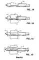
- FIGS. 1A-1Dillustrate an exemplary biopsy probe 10 .
- the distal ends of probes 10 of these biopsy systemsare adapted to both penetrate tissue and to contain a cutting member 12 which facilitates the removal of the biopsy sample.
- the cutting member 12will contain an aperture 14 (often referred to as a “probe window.”)
- the aperture 14may be located on a side of a probe 10 .
- the cutting member 12 of the probe 10aligns with suspect tissue 1 via stereotactic, ultrasound, or other means.
- a vacuumdraws the breast tissue 1 through the probe aperture 14 into the probe 10 .
- the cutting member 12actuates to capture a tissue sample 3 .
- the tissue sample 3may then be retrieved through the probe 10 to a tissue collection area (e.g., a standard pathology tissue cassette).
- FIG. 1Cillustrates the probe 10 after the tissue sample is cleared from the aperture 14 . Note that the illustration depicts a portion of the cutting member 12 as being retracted, leaving aperture 14 open; the cutting member 12 may alternatively be placed in a closed position during retrieval of the tissue sample.
- the biopsy systemis often adapted such that the cutting member 12 and aperture 14 rotate (e.g., via manipulation of a thumbwheel on the probe or biopsy system) with respect to the biopsy system.
- the radiologist or surgeonmay rotate the probe 10 and the aperture 14 to a new position relative to the biopsy system.
- FIG. 1Dillustrates the probe 10 and aperture 14 after being rotated but without being removed from the body. The rotation of the probe 10 and aperture 14 permits excision of multiple subsequent biopsy samples from a target area of suspect tissue with only a single insertion of the biopsy probe 10 .
- FIG. 1Dis provided merely to illustrate the rotation of the probe 10 within the body. As such, the placement of biopsy markers is not illustrated in the figure.
- the cutting member 12is depicted in a closed position. This may ease rotation of the probe 10 within the tissue.
- the entire cyclemay be repeated until sampling of all desired areas occurs (typically, 8 to 30 samples of breast tissue are taken up to 360 degrees around the suspect area). Accordingly, it is important that the operator of the biopsy system is able to identify the orientation of the probe aperture 14 relative to the biopsy system at any given time while the probe aperture 14 remains within the tissue. Often, demarcations on the thumbwheel permit the identification of the probe orientation.
- tissue cavitiescreate tissue cavities.
- placement of a biopsy marker through the probeis most desirable.
- repeated removal of the probe and insertion of a biopsy marking devicemay cause unneeded additional discomfort to the patient undergoing the procedure; removal of the probe may introduce error in placement of the biopsy marker into the desired location; repeated removal and insertion of each of the devices may prolong the duration of the procedure or spread cancer cells; after the probe removes a tissue sample, it is in the optimal location to deposit a marker; etc.
- Biopsiesmay be performed with other tissue sampling devices as described in U.S. Pat. Nos.: U.S. Pat. Nos. 4,699,154; 4,944,308, and 4,953,558 the entirety of each of which is incorporated by reference herein.
- tissue sampling devicesobtain a biopsy sample through a hollow biopsy needle having an aperture located in a distal end of the biopsy needle.
- tissue sampling devicesremoves tissue and creates a biopsy cavity, it may be desirable to place a marker in the area of the biopsy cavity.
- a basic variation of the inventionincludes a tissue marker delivery device comprising a tube having a lumen extending therethrough, a tissue marker removably seated in a distal end of the tube, a rod slidably located within the tube lumen and having a first end extending through a proximal end of tube and a second end in the tube lumen; and an intermediate member separating the rod from the biopsy marker, where advancement of the rod in a distal direction displaces the intermediate member to displace the tissue marker from said marker seat.
- the intermediate memberis discrete from both the rod and the tissue marker.
- the intermediate membermay comprises a flexible covering as described herein.
- a delivery devicefor use with a biopsy probe having an aperture
- the delivery devicecomprising a body having proximal and distal ends and a passageway extending therethrough, an elongate sheath having a lumen extending therethrough, the sheath extending distally from the distal end of the body, the sheath lumen in fluid communication with the body passageway, an access tube having a proximal and a distal end and a lumen extending from at least a portion of the access tube through the proximal end, the access tube slidably located within the body passageway and the sheath lumen, a marker seat located towards the distal end of the access tube, a rod slidably located within the access tube lumen and having a first end extending through the proximal end of the body and a second end in communication with the marker seat, wherein advancement of the rod in a distal direction advances the marker seat distally until the marker seat is adjacent to the probe aperture such that a marker in
- the marker seatwhen using a biopsy probe having an aperture in a side wall of the probe, the marker seat may be advanced within the aperture and subsequently deploys a marker.
- the marker seatWhen the inventive device is used with biopsy probes having an aperture in a distal end of the probe, the marker seat may be advanced just proximal to the aperture in preparation for subsequent deployment of the marker.
- the rodmay advance the marker seat through a number of configurations.
- the rodmay be sized to have an interference fit with a portion of the access tube lumen.
- Another exampleincludes a device configured such that the rod engages a marker which is situated in the marker seat. In such a case, a sheath may restrain the marker in the marker seat. Thus, until the marker is no longer constrained by the sheath, the rod will advance the marker within the sheath.
- the rodmay be in communication with a fluid that is itself in communication with the marker seat. In such a case, the rod may apply a force on the fluid to advance the marker seat and/or displace a marker from the marker seat. In some variations, the fluid may serve to displace a flexible covering out of the marker seat. It is contemplated that the rod of the present invention may advance the marker seat through a combination of configurations either described herein or known to those familiar with similar delivery devices.
- a variation of the inventionalso includes a delivery device as described above, wherein the body further comprises a keyway along the passageway, and the body has an orientation being defined relative to the keyway, the delivery device further comprising an access tube key located on the access tube and adapted to be slidably located within the body keyway, the access tube key adapted to maintain an orientation of the access tube with the body orientation.
- Variations of the inventionmay also include a deployment lock having a first end and a second end, the first end moveably located in the body and the second end located outside of the body, the first end adapted to engage a portion of the rod to prevent at least distal movement of the rod, whereupon disengagement of the first end of the deployment lock from the portion of the rod permits distal movement of the rod.
- the deployment lockmay be removable from the device or may be moveable within the device so as to permit disengagement of the lock from the rod while still being attached to the body of the device.
- the inventionalso may include a rod stop fixedly located on the rod, wherein after the rod is advanced into the marker seat, the rod stop engages the access tube stop preventing further distal movement of the rod.
- the rod stopmay also include a rod key that is adapted to maintain an orientation of the rod with the body orientation.
- a variation of the deviceincludes an access tube stop fixedly located on a portion of the access tube being located within the body, wherein advancement of the rod in a distal direction advances the marker seat distally until the access tube stop engages the distal end of the body preventing further distal movement of the access tube whereupon further distal advancement of the rod advances into the marker seat.
- engagement of the access tube stop against the distal end of the bodyplaces the marker seat adjacent to the biopsy probe aperture.
- a portion of the distal end of the access tubeis removed to define the marker seat.
- the inventionmay also include a covering located over at least the marker seat, where at least a portion of the covering is adapted to displace into and out of the marker seat. Movement of the rod into the marker seat displaces the covering out of the marker seat.
- the actuatore.g., rod, etc.
- the inventive deviceincludes a delivery device key adapted to seat in the biopsy probe and maintain an orientation of the access tube with an orientation of the biopsy probe.
- the delivery device keymay be located on the elongated sheath or on the body of the device. In some variations of the invention, seating the delivery device key in the biopsy probe will cause a distal end of the outer sheath to be placed immediately proximal to the biopsy probe aperture.
- Variations of the inventionalso may include a biopsy marker that is seated in the marker seat.
- the delivery device and method described herein for delivering a marking device to a subcutaneous cavityis suited for use with a biopsy probe, the invention is not necessarily limited as such. Variations of the inventive device may be used with any type of biopsy procedure.
- the inventionalso contains a kit containing a biopsy marker delivery device as described herein and an introducer cannula.
- the introducer cannulamay be used to facilitate insertion of the delivery device into the patient to assist in delivery of a biopsy marker.
- the kitmay also include a biopsy probe.
- the biopsy probemay be a spring-loaded biopsy probe.
- the inventionalso includes a method for marking a biopsy cavity.
- the inventive methodincludes using a delivery device having a marker, a tube removably seating the marker, a rod within the tube, and an intermediate member separating the rod and the marker, the method comprising, advancing the marker and delivery device to the biopsy cavity, actuating the rod to displace the intermediate member on the delivery device; and depositing the marker in the cavity upon displacing the intermediate member.
- FIG. 1Aillustrates biopsy probe for use with variations of the present invention.
- FIG. 1Billustrates the biopsy probe of FIG. 1A in which tissue is drawn through an aperture of the probe for excision of a biopsy sample.
- FIG. 1Cillustrates the biopsy probe of FIG. 1A where the biopsy sample is cleared from the aperture.
- FIG. 1Dillustrates the biopsy probe of FIG. 1A rotated within the body.
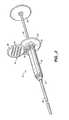
- FIG. 2provides a perspective view of a variation of a delivery device of the present invention.
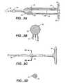
- FIGS. 3A-3Killustrate various components that may be used in delivery devices of the present invention.
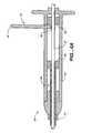
- FIGS. 4A-4Cprovide cross sectional views of a portion of a delivery device of the present invention during actuation of the device.
- FIGS. 5A-5Dillustrate cross sectional views of a delivery device of the present invention deploying a marker.
- FIG. 2illustrates a perspective view of a variation of a biopsy marker delivery device 20 of the present invention.
- the delivery device 20includes a body 22 having an elongate sheath 28 extending from a distal end 24 of the body 22 and a rod 30 extending from a proximal end 26 of the body 22 .
- This variation of the device 20also includes a deployment lock 32 having a first end 34 moveably located in the body 22 of the device 20 and second end 36 located outside of the body 22 . As discussed below, the first end 34 of the deployment lock 32 engages a portion (not shown) of the rod 30 preventing distal movement of the rod. Disengagement of the first end 34 of the deployment lock 32 from the rod 30 permits movement of the rod 30 within the device 20 .
- the device 20may incorporate features to permit ease in handling the device 20 .
- the proximal ends of the body 22 and the rod 30each may have portions 40 , 42 of increased surface area that assist in the ability to actuate the device.
- the second end 36 of the deployment lockmay have raised surface areas 44 that permit an operator to grip the deployment lock 32 when an operator disengages the first end 34 of the deployment lock 32 from the rod 30 .
- Such featureswhich permit ease in handling the device, are well known to those skilled in the art and are not meant to limit the scope of the invention.
- FIG. 3Aillustrates a cross sectional view of a body 22 and elongate sheath 28 of a variation of the inventive device.
- the body 22has a proximal end 26 , a distal end 24 , and a passageway 46 extending through the body 22 .
- the variation of the body 22 depicted in FIG. 3Aalso contains a keyway 48 extending through at least a portion of the body passageway 46 .
- the keyway 48permits alignment and/or maintaining orientation of components of the inventive device with an orientation of the body 22 .
- the ability to identify an orientation of the device relative to, for example, a biopsy probeis desirable for proper deployment of a biopsy marker.
- the keyway 48may be a male or female keyway which permits mating of a corresponding key such that a component having such a key will maintain orientation while moved through the device.
- the distal end 24 of body 22includes an end component 50 that reduces a diameter of the passageway 46 therethrough.
- the body 22may be optionally designed without such an end component 50 .
- the body 22could be designed as a unitary piece.
- the body passageway 46may optionally have an area of reduced diameter at the distal end 24 . This area of reduced diameter made from a uniform reduction of the diameter of the passageway 46 or may have one or more protrusions which effectively reduce the diameter of the passageway 46 .
- the body 22may also include an opening 52 through which a deployment lock may be inserted through the body 22 .
- the body 22may also include a portion 40 of increased surface area that permits handling of the device.
- the bodymay be formed out of materials such as ABS, polycarbonate, acetal, or acrylic.
- the inventive devicealso includes an elongate sheath 28 extending distally from a distal end 24 of the body 22 .
- the elongate sheath 28contains a lumen (not shown) that extends through the sheath 28 .
- the sheath lumenis in fluid communication with the body passageway 46 .
- fluid communicationit is meant that the passageways merely intersect or join one another.
- the elongate sheath 28may be flexible such that the sheath 28 may be advanced to a biopsy site, either through a device, such as a biopsy probe, cannula, etc., or through a biopsy tract created by the biopsy procedure.
- variations of the inventionmay include sheaths 28 that may have sufficient rigidity to access the biopsy cavity (in some cases the sheath 28 may even contain a reinforcing member, e.g., a braid, stiffening member.)
- the sheathmay comprise materials such as polyethylene (PE), especially high density PE (HDPE), nylon, urethane, or a fluoropolymer.
- a variation of the inventive device, as illustrated in FIG. 3Amay also contain a delivery device key 38 .
- the delivery device key 38may be located on the elongated sheath 28 (as illustrated) or may be located on the body 22 . As discussed above, it may be necessary to rotate a biopsy probe to retrieve multiple tissue samples.
- the delivery device key 38is adapted to be seated into a biopsy probe (not shown) such that when the biopsy probe is rotated, an orientation of the device may match the orientation of the aperture of the biopsy probe.
- the delivery device key 38may include a raised protrusion or other surface which may mate with a portion of the biopsy probe.
- the length of the elongate sheath 28is selected such that when the delivery device key 38 is engaged in a biopsy probe, the distal end of the elongate sheath 28 is located adjacent to an aperture of the biopsy probe.
- FIG. 3Billustrates a cross sectional view of a variation of a deployment lock 32 of the inventive device.
- the deployment lock 32includes a first end 34 and a second end 36 .
- the first end 34 of the deployment lock 32is adapted to be inserted into the device body and to engage a portion of a rod (as illustrated below) to at least prevent the rod from distal movement through the device.
- the second end 36 of the deployment lock 32may be located outside of the device body and is adapted to permit disengagement of the deployment lock 32 from the rod.
- the variation of the deployment lock 32 depicted in FIG. 3Bis adapted to be removed from the device via pulling the second end 36 of the deployment lock 32 .
- variations of deployment locks of the present inventionmay remain within the device while simultaneously disengaging from a rod to permit movement of the rod. Additionally, variations of the deployment lock 32 may also contain one or more securing arms 51 , which assist in retention of the deployment lock 32 in a “locked” position.
- FIG. 3Cillustrates a side view of a rod 30 of the present invention.
- the rod 30may be a tubular or other member.
- the rod 30may have a lumen extending therethrough.
- the rod 30may be flexible as required to navigate through a sheath which may itself be located in a biopsy probe. Some materials from which the rod may be constructed include nylon, urethane, PE, and fluoropolymers.
- the rod 30may have a portion 42 of increased surface area or increased diameter at a proximal end or along any length of the rod 30 .
- the rod 30also includes a rod stop 54 located along a length of the rod 30 .
- FIG. 3Dillustrates a cross sectional view of the rod stop 54 taken along the line 3 D— 3 D of FIG. 3 C.
- variations of the rod stop 54may include a rod key 56 .
- the rod key 56is adapted to mate with the body keyway to maintain the orientation of the rod with respect to the device.
- the rod key 56 depicted in FIG. 3Dis a male key
- the rod key 56is intended to mate with the corresponding keyway.
- the rod key 56may be a female rather than male fitting.
- the rod key 56 of the present inventionis not limited to placement on the rod stop 54 .
- variations of the inventive devicemay include a rod key which may be located on a rod 30 as opposed to the rod stop 54 .
- FIG. 3Eillustrates a side view of a variation of an access tube 58 of the present invention.
- the access tube 58comprises proximal 68 and distal ends 70 with a lumen 72 extending at least from a portion of the tube 58 through the proximal end 68 .
- the lumenmay extend throughout the tube.
- the lumenmay also be closed at a distal end 70 such that when a biopsy marker (not shown) is placed in a marker seat 62 , the biopsy marker is prevented from advancing distally within the access tube. This is especially useful when side ejection of a marker is desired.
- the closed distal end 70prevents a marker from remaining within a portion of the lumen 72 of the tube 58 at the distal end 70 .
- the distal end 70may be either closed or have a occluding member placed therein.
- the access tube 58may be flexible as required by the procedure being used to access a biopsy cavity.
- the access tube 58may be constructed from materials such as nylon, urethane, PE, or a fluoropolymer.
- the access tubemay also include an access tube stop 60 .
- the access tube stop 60is located at the proximal end 68 of the access tube 58 .
- the inventionis not limited as such as the access tube stop 60 may be located over any portion of the access tube 58 .
- FIG. 3Fillustrates a cross-sectional view of the access tube stop 60 of FIG. 3E as taken along lines 3 F— 3 F.
- the access tube stop 60also contains an access tube key 66 .
- the access tube key 66mates with a body keyway such that the access tube 58 and marker seat 62 are able to maintain a desired orientation within the device.
- the access tube key 66may be male or female depending upon the body keyway.
- the access tube 58will contain a marker seat 62 located towards a distal end 70 of the tube 58 .
- the marker seat 62will be adapted depending upon the biopsy marker used with the device.
- a marker seat 62may be formed by removing a portion of the access tube 58 .
- the inventionmay have an intermediate member that separates the biopsy marker from the actuating member of the device (e.g., the rod, etc.) and ejects/deploys the marker from the device.
- the intermediate coveringmay be discrete from the tube and tissue marker, e.g., a flexible covering 64 as described below.
- a portion of the tube itselfcould be configured to serve as the intermediate member (e.g., a weakened section of a tube that is adapted to fold into the tube lumen to seat the marker and unfold from the lumen to deploy the marker.)
- a variation of the inventionincludes an intermediate member that is a flexible covering 64 .
- the flexible covering 64may be located over a portion of the tube 58 which includes the marker seat 62 .
- FIG. 3Gillustrates a cross-sectional view of the marker seat 62 taken along the line 3 G— 3 G of FIG. 3 E.
- FIG. 3Gillustrates the marker seat 62 covered by the flexible covering 64 .
- at least a portion of the flexible covering 64is placed or folded into the marker seat 62 .
- the flexible covering 64assists in deployment of the marker as the flexible covering 64 may be displaced and/or unfolded out of the marker seat 62 .
- the flexible coveringmay be made from any commercially available medical grade flexible material such as polyethylene terephthalate (PET), polytetrafluoroethylene (PTFE), or FEP.
- PETpolyethylene terephthalate
- PTFEpolytetrafluoroethylene
- FEPFEP
- FIG. 3Ealso illustrates a rod 30 slidably located within the access tube 58 where a distal end of the rod 30 may be located adjacent to the marker seat 62 . Distal advancement of the rod 30 advances the access tube 58 within the device. In one variation, the distal end of the rod 30 may be urged against a marker (not shown) seated in the marker seat 62 . Since the marker will be constrained within the marker seat, which is located within an elongate sheath (not shown), the marker will be unable to deploy from the marker seat 62 . Accordingly, as a result of the rod 30 pushing against the marker (constrained within the marker seat 62 ) the access tube 58 and marker seat 62 advance with the rod 30 .
- the marker and marker seatare either placed within or advanced out of an aperture of the biopsy probe, then the force of the rod 30 applied against the marker will eject the marker from the marker seat 62 .
- the distal end of the rod 30 and the lumen 72 of the access tube 58may be sized such to provide a friction fit between the lumen 72 and the rod 30 .
- the friction fitpermits the rod 30 to advance the access tube 58 until the access tube 58 meets with sufficient resistance to permit the rod 30 to advance independently of the access tube 58 .
- advancement of the rod 30 in a distal directionadvances the marker seat 62 distally until the marker seat 62 is adjacent to the probe aperture such that a marker located in the marker seat 62 may be ejected from the probe aperture.
- the inventionincludes variations where the rod advances the marker seat through a combination of configurations either described herein or known to those familiar with similar delivery devices.
- FIG. 3Hillustrates a side view of a portion of the access tube 58 of FIG. 3 E.
- the rod 30is able to advance independently of the access tube 58 and advances into the marker seat 62 .
- the rod 30displaces and/or unfolds the flexible covering 64 out of the marker seat 62 .
- this actionpermits the deployment of the marker (not shown) seated within the marker seat 62 .
- the rod 30may deploy the marker via direct contact.
- the distal end of the rod 30is adapted to assist in deploying the marker (e.g., the distal end of the rod may be tapered, rounded, hinged to eject the marker, etc.)
- Variations of the inventionalso include a marker seat that permits deployment of a marker through a distal opening in the lumen of the elongate sheath.
- FIG. 3Iillustrates another variation of the present invention.
- a rod 30is slidably located within the access tube 58 where a distal end 76 of the rod 30 is adjacent to a fluid 74 .
- distal advancement of the rod 30also advances the access tube 58 within the device when a marker (not shown) is constrained in the marker seat 62 by an outer sheath (not shown.) Such a result occurs as advancement of the rod 30 displaces the fluid 74 . Because the marker is constrained in the marker seat 62 , the fluid 74 cannot displace the flexible covering 64 from the marker seat 62 .
- the force on the fluid 74 applied by the distal end 76 of the rod 30acts to distally advance the marker seat 62 and marker out of the sheath. Once the marker is advanced out of the sheath and is no longer constrained, the force applied by the distal end 76 of the rod 30 displaces the fluid 74 which displaces the flexible covering 64 thereby ejecting the marker from the marker seat 62 .
- FIG. 3Jillustrates a state of the device after the marker is freed from constraint by the sheath.
- the displacement of the fluid 74 by the distal end of the rod 76displaces the flexible covering 64 from the marker seat 62 to eject the marker.
- the distal end 76 of the rod 30may be adapted such that it forms a seal (e.g., through sizing, use of a sealing gasket, etc.) with the lumen 72 of the access tube 58 .
- the rod 30may be entirely replaced with fluid.
- a syringe or similar apparatuswould provide an actuator/pressure source to displace the fluid and deploy the marker.
- the flexible covering 64may also be fluid-tight such that the fluid cannot escape from the device.
- FIGS. 3I and 3Jshow the flexible covering 64 as having fluid tight seals 78 . It is noted that the position of the seals 78 , as illustrated, is merely for exemplary purposes as the seals may be placed in any position such that fluid does not escape. As is apparent, in most cases, the distal end 70 of the access tube 58 will be sealed to prevent leakage of the fluid 74 .
- the distal end 70may be adapted to deliver or leak the fluid in a controlled manner.
- the fluid 74may be any biocompatible liquid or gas, e.g., saline fluid, air, etc.
- the fluidmay compress. In such cases, it may become necessary to add additional fluid 74 to the device.
- FIG. 3Killustrates a variation of an access tube 58 for use with the present invention.
- the distal end 70 of the access tube 58may be tapered to permit the access tube 58 to enter a cavity where tissue has collapsed or narrowed the tract entering the cavity.
- rod 30 and access tube 58 of the present inventionmay be sufficiently flexible to navigate through a biopsy probe, cannula, etc., to access a biopsy site.
- some applicationsmay require variations of the invention having a rigid access tube and rod.
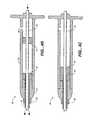
- FIG. 4Aillustrates a cross sectional view of a portion of a variation of inventive delivery device 20 .
- the device 20is in a “locked” position as the deployment lock 32 engages a portion of the rod 30 to prevent at least distal movement of the rod 30 .
- a first end 34 of the deployment lock 32engages a rod stop 54 on a rod 30 .
- the deployment lock 32may be removed from the body 22 , variations of the invention contemplate that the deployment lock 32 may disengage from the rod 30 while remaining attached to the body 22 .
- the devicemay have a delivery device key (not shown) as well.
- the delivery device keypermits the orientation of the device to match the orientation of the probe aperture as it is rotated within the body of a patient. Moreover, the delivery device key may be placed such that the distal end of the elongate sheath 28 is placed adjacent to the probe aperture when the delivery device key is engaged to the biopsy probe.
- FIG. 4Billustrates a cross sectional view of a portion of the variation of the inventive delivery device 20 where the deployment lock (not shown) is removed from the body 22 via an opening 52 in the body 22 .
- the rod 30is able to be advanced in a distal direction within the device 20 .
- advancement of the rod 30permits advancement of a access tube 58 within the device 20 .
- the access tube 58is prevented from further distal movement. Therefore, once the access tube 58 advances out of a distal end of the elongated sheath 28 , the access tube stop 60 engages the distal end 24 of the body 22 preventing further distal movement.
- the access tube 58advances sufficiently to permit advancement of the marker seat out of the distal end of the sheath 28 .
- the body 22may also contain a keyway (not shown) as discussed above. Accordingly, the access tube 58 will contain a corresponding key which permits the orientation of the access tube to match the orientation of the device. Maintaining this orientation may also permit the marker seat to be oriented within the device 20 such that it is aligned with an aperture of a probe to permit deployment of the marker through the probe aperture.
- distal movement of the rod 30advances the marker seat distally due to the distal end of the rod pushing against a marker within the marker seat. Since the marker is constrained by the sheath and/or biopsy probe, it remains within the marker seat. Once the marker is advanced out of the sheath 28 and is placed adjacent to the probe-aperture, it is no longer constrained by the sheath 28 or the biopsy probe. At this point, further distal movement of the rod 30 ejects the now unconstrained marker from the marker seat through the probe aperture and into a biopsy cavity.
- FIG. 4Cillustrates a cross sectional view of the device 20 of FIG. 4B where the rod 30 is further distally advanced to deploy a marker.
- the rodcontains a rod stop 54 which limits the distal advancement of the rod 30 .
- the device 20will be configured such that the rod 30 is able to deploy the marker prior to being prevented from further distal advancement.
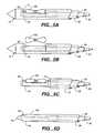
- FIGS. 5A-5Billustrate a partial cross sectional view of a variation of a delivery device of the present invention for use with a biopsy probe 10 .
- FIG. 5Aillustrates the inventive delivery device after the access tube 58 is advanced out of the elongate sheath 28 .
- the elongate sheath 28may be placed immediately adjacent to an aperture 14 of the probe 10 and the access tube 58 is advanced within the aperture 14 .
- the devicemay permit orientation of the components of the device with the aperture 14 of the probe 10 .
- FIG. 5Billustrates the invention where the rod 30 may move independently of the access tube 58 .
- distal movement of the rod 30may force the flexible covering 64 out of the marker seat 62 thereby deploying the marker 100 .
- FIG. 5Cillustrates the use of the inventive device used with a probe 10 that contains a distal aperture 14 (e.g., a biopsy needle, etc.) In this case, the device is advanced out of the aperture 14 so that the marker 100 may be deployed in a biopsy cavity.
- FIG. 5Dillustrates another variation of the inventive device where a distal end 70 of the rod 30 permits advancement of the device through a tissue tract (the channel leading from the biopsy cavity to the outside of the patient's body which is created during the biopsy procedure) that may constrict in diameter.
- the sheath 28may also be adapted to facilitate advancement through a narrowed tissue tract. For instance, if a biopsy probe is removed from the site, the device illustrated in FIG. 5D may be solely advanced into the tissue tract to deposit the biopsy marker 100 .
- the device illustrated in FIG. 5Dmay be used with a biopsy probe as shown in FIG. 5 C.
- the inventionprovides an improved biopsy marker delivery system. While the above descriptions have described the invention for use in the marking of biopsy cavities made through a vacuum-assisted breast biopsy procedure, the invention is not limited to such. The invention disclosed herein may be used with any biopsy procedure discussed herein or otherwise known.
Landscapes
- Health & Medical Sciences (AREA)
- Life Sciences & Earth Sciences (AREA)
- Surgery (AREA)
- Biomedical Technology (AREA)
- Engineering & Computer Science (AREA)
- Heart & Thoracic Surgery (AREA)
- Medical Informatics (AREA)
- Molecular Biology (AREA)
- Pathology (AREA)
- Animal Behavior & Ethology (AREA)
- General Health & Medical Sciences (AREA)
- Public Health (AREA)
- Veterinary Medicine (AREA)
- Nuclear Medicine, Radiotherapy & Molecular Imaging (AREA)
- Oral & Maxillofacial Surgery (AREA)
- Surgical Instruments (AREA)
Abstract
Description
Claims (10)
Priority Applications (2)
| Application Number | Priority Date | Filing Date | Title |
|---|---|---|---|
| US10/639,050US7083576B2 (en) | 2001-09-10 | 2003-08-11 | Biopsy marker delivery system |
| US11/496,830US20080188768A1 (en) | 2001-09-10 | 2006-07-31 | Biopsy marker delivery system |
Applications Claiming Priority (2)
| Application Number | Priority Date | Filing Date | Title |
|---|---|---|---|
| US09/954,792US6605047B2 (en) | 2001-09-10 | 2001-09-10 | Biopsy marker delivery system |
| US10/639,050US7083576B2 (en) | 2001-09-10 | 2003-08-11 | Biopsy marker delivery system |
Related Parent Applications (1)
| Application Number | Title | Priority Date | Filing Date |
|---|---|---|---|
| US09/954,792ContinuationUS6605047B2 (en) | 2001-09-10 | 2001-09-10 | Biopsy marker delivery system |
Related Child Applications (1)
| Application Number | Title | Priority Date | Filing Date |
|---|---|---|---|
| US11/496,830ContinuationUS20080188768A1 (en) | 2001-09-10 | 2006-07-31 | Biopsy marker delivery system |
Publications (2)
| Publication Number | Publication Date |
|---|---|
| US20040049126A1 US20040049126A1 (en) | 2004-03-11 |
| US7083576B2true US7083576B2 (en) | 2006-08-01 |
Family
ID=25495936
Family Applications (3)
| Application Number | Title | Priority Date | Filing Date |
|---|---|---|---|
| US09/954,792Expired - LifetimeUS6605047B2 (en) | 2001-09-10 | 2001-09-10 | Biopsy marker delivery system |
| US10/639,050Expired - Fee RelatedUS7083576B2 (en) | 2001-09-10 | 2003-08-11 | Biopsy marker delivery system |
| US11/496,830AbandonedUS20080188768A1 (en) | 2001-09-10 | 2006-07-31 | Biopsy marker delivery system |
Family Applications Before (1)
| Application Number | Title | Priority Date | Filing Date |
|---|---|---|---|
| US09/954,792Expired - LifetimeUS6605047B2 (en) | 2001-09-10 | 2001-09-10 | Biopsy marker delivery system |
Family Applications After (1)
| Application Number | Title | Priority Date | Filing Date |
|---|---|---|---|
| US11/496,830AbandonedUS20080188768A1 (en) | 2001-09-10 | 2006-07-31 | Biopsy marker delivery system |
Country Status (4)
| Country | Link |
|---|---|
| US (3) | US6605047B2 (en) |
| EP (1) | EP1424930B8 (en) |
| DE (1) | DE60239687D1 (en) |
| WO (1) | WO2003022133A2 (en) |
Cited By (54)
| Publication number | Priority date | Publication date | Assignee | Title |
|---|---|---|---|---|
| US20060247673A1 (en)* | 2005-04-08 | 2006-11-02 | Voegele James W | Multi-port laparoscopic access device |
| US20070118034A1 (en)* | 2005-11-22 | 2007-05-24 | Mark Joseph L | Surgical site marker delivery system |
| US20070142725A1 (en)* | 2005-12-16 | 2007-06-21 | Hardin Terry D | Biopsy site marker deployment device |
| US20080228164A1 (en)* | 2007-03-14 | 2008-09-18 | Nicoson Zachary R | Implant delivery system |
| US20090270760A1 (en)* | 2008-04-23 | 2009-10-29 | Leimbach Jessica P | Biopsy Devices |
| US20090270725A1 (en)* | 2008-04-23 | 2009-10-29 | Leimbach Jessica P | Devices Useful In Imaging |
| US20100160777A1 (en)* | 2008-12-22 | 2010-06-24 | Hardin Terry D | Reverse deployment device |
| US7819820B2 (en) | 2003-11-17 | 2010-10-26 | Bard Peripheral Vascular, Inc. | Self contained, self piercing, side-expelling marking apparatus |
| US20110028793A1 (en)* | 2009-07-30 | 2011-02-03 | Ethicon Endo-Surgery, Inc. | Methods and devices for providing access into a body cavity |
| US8052708B2 (en) | 1999-06-17 | 2011-11-08 | Bard Peripheral Vascular, Inc. | Apparatus for the percutaneous marking of a lesion |
| US8064987B2 (en) | 2006-10-23 | 2011-11-22 | C. R. Bard, Inc. | Breast marker |
| US8157862B2 (en) | 1997-10-10 | 2012-04-17 | Senorx, Inc. | Tissue marking implant |
| US8177792B2 (en) | 2002-06-17 | 2012-05-15 | Senorx, Inc. | Plugged tip delivery tube for marker placement |
| US8219182B2 (en) | 1999-02-02 | 2012-07-10 | Senorx, Inc. | Cavity-filling biopsy site markers |
| US8224424B2 (en) | 1999-02-02 | 2012-07-17 | Senorx, Inc. | Tissue site markers for in vivo imaging |
| US8226553B2 (en) | 2009-03-31 | 2012-07-24 | Ethicon Endo-Surgery, Inc. | Access device with insert |
| US8311610B2 (en) | 2008-01-31 | 2012-11-13 | C. R. Bard, Inc. | Biopsy tissue marker |
| US8353824B2 (en) | 2009-03-31 | 2013-01-15 | Ethicon Endo-Surgery, Inc. | Access method with insert |
| US8357085B2 (en) | 2009-03-31 | 2013-01-22 | Ethicon Endo-Surgery, Inc. | Devices and methods for providing access into a body cavity |
| US8361082B2 (en) | 1999-02-02 | 2013-01-29 | Senorx, Inc. | Marker delivery device with releasable plug |
| US8401622B2 (en) | 2006-12-18 | 2013-03-19 | C. R. Bard, Inc. | Biopsy marker with in situ-generated imaging properties |
| US8419656B2 (en) | 2004-11-22 | 2013-04-16 | Bard Peripheral Vascular, Inc. | Post decompression marker introducer system |
| US8447386B2 (en) | 2003-05-23 | 2013-05-21 | Senorx, Inc. | Marker or filler forming fluid |
| US8460337B2 (en) | 2010-06-09 | 2013-06-11 | Ethicon Endo-Surgery, Inc. | Selectable handle biasing |
| US8486028B2 (en) | 2005-10-07 | 2013-07-16 | Bard Peripheral Vascular, Inc. | Tissue marking apparatus having drug-eluting tissue marker |
| US8498693B2 (en) | 1999-02-02 | 2013-07-30 | Senorx, Inc. | Intracorporeal marker and marker delivery device |
| US8562592B2 (en) | 2010-05-07 | 2013-10-22 | Ethicon Endo-Surgery, Inc. | Compound angle laparoscopic methods and devices |
| US8626269B2 (en) | 2003-05-23 | 2014-01-07 | Senorx, Inc. | Fibrous marker and intracorporeal delivery thereof |
| US8634899B2 (en) | 2003-11-17 | 2014-01-21 | Bard Peripheral Vascular, Inc. | Multi mode imaging marker |
| US8670818B2 (en) | 2008-12-30 | 2014-03-11 | C. R. Bard, Inc. | Marker delivery device for tissue marker placement |
| US8668737B2 (en) | 1997-10-10 | 2014-03-11 | Senorx, Inc. | Tissue marking implant |
| US8718745B2 (en) | 2000-11-20 | 2014-05-06 | Senorx, Inc. | Tissue site markers for in vivo imaging |
| USD715442S1 (en) | 2013-09-24 | 2014-10-14 | C. R. Bard, Inc. | Tissue marker for intracorporeal site identification |
| USD715942S1 (en) | 2013-09-24 | 2014-10-21 | C. R. Bard, Inc. | Tissue marker for intracorporeal site identification |
| USD716450S1 (en) | 2013-09-24 | 2014-10-28 | C. R. Bard, Inc. | Tissue marker for intracorporeal site identification |
| USD716451S1 (en) | 2013-09-24 | 2014-10-28 | C. R. Bard, Inc. | Tissue marker for intracorporeal site identification |
| US9149341B2 (en) | 1999-02-02 | 2015-10-06 | Senorx, Inc | Deployment of polysaccharide markers for treating a site within a patient |
| US9226760B2 (en) | 2010-05-07 | 2016-01-05 | Ethicon Endo-Surgery, Inc. | Laparoscopic devices with flexible actuation mechanisms |
| US9327061B2 (en) | 2008-09-23 | 2016-05-03 | Senorx, Inc. | Porous bioabsorbable implant |
| US9333001B2 (en) | 2009-10-08 | 2016-05-10 | Ethicon Endo-Surgery, Inc. | Articulable laparoscopic instrument |
| US9579077B2 (en) | 2006-12-12 | 2017-02-28 | C.R. Bard, Inc. | Multiple imaging mode tissue marker |
| EP2644105A3 (en)* | 2006-10-24 | 2017-06-14 | C.R. Bard, Inc. | Large sample low aspect ratio biopsy needle |
| US20170231716A1 (en)* | 2014-11-06 | 2017-08-17 | Devicor Medical Products, Inc. | Spring-ejected biopsy marker |
| US9737334B2 (en) | 2009-03-06 | 2017-08-22 | Ethicon Llc | Methods and devices for accessing a body cavity |
| US9820824B2 (en) | 1999-02-02 | 2017-11-21 | Senorx, Inc. | Deployment of polysaccharide markers for treating a site within a patent |
| US10342635B2 (en) | 2005-04-20 | 2019-07-09 | Bard Peripheral Vascular, Inc. | Marking device with retractable cannula |
| US10683119B2 (en) | 2014-05-23 | 2020-06-16 | Merit Medical Systems, Inc. | Marker element, device for making a marker element, and method for making a marker element |
| US11007030B2 (en) | 2018-07-12 | 2021-05-18 | Davol Inc. | Surgical instrument with fastener preload lock-out |
| US11864750B2 (en) | 2020-04-29 | 2024-01-09 | Medos International Sarl | Knotless anchor insertion |
| USD1019945S1 (en) | 2021-12-30 | 2024-03-26 | Medos International Sarl | Suture anchor insertion device |
| USD1028232S1 (en) | 2021-04-27 | 2024-05-21 | Medos International Sarl | Suture anchor insertion device |
| US12029416B2 (en) | 2019-04-17 | 2024-07-09 | Davol Inc. | Surgical instrument with fastener preload lock-out |
| US12137894B2 (en) | 2021-12-30 | 2024-11-12 | Medos International Sarl | Knotless anchor inserter tool extraction |
| US12426860B2 (en) | 2018-04-18 | 2025-09-30 | C.R. Bard, Inc. | Dual lumen coaxial introducer having integrated tissue marker delivery |
Families Citing this family (65)
| Publication number | Priority date | Publication date | Assignee | Title |
|---|---|---|---|---|
| US6270464B1 (en) | 1998-06-22 | 2001-08-07 | Artemis Medical, Inc. | Biopsy localization method and device |
| US6347241B2 (en)* | 1999-02-02 | 2002-02-12 | Senorx, Inc. | Ultrasonic and x-ray detectable biopsy site marker and apparatus for applying it |
| US20020058882A1 (en)* | 1998-06-22 | 2002-05-16 | Artemis Medical, Incorporated | Biopsy localization method and device |
| US6440147B1 (en)* | 1998-09-03 | 2002-08-27 | Rubicor Medical, Inc. | Excisional biopsy devices and methods |
| US6022362A (en)* | 1998-09-03 | 2000-02-08 | Rubicor Medical, Inc. | Excisional biopsy devices and methods |
| US7517348B2 (en) | 1998-09-03 | 2009-04-14 | Rubicor Medical, Inc. | Devices and methods for performing procedures on a breast |
| US6936014B2 (en)* | 2002-10-16 | 2005-08-30 | Rubicor Medical, Inc. | Devices and methods for performing procedures on a breast |
| US7329253B2 (en)* | 2003-12-09 | 2008-02-12 | Rubicor Medical, Inc. | Suction sleeve and interventional devices having such a suction sleeve |
| AU2002320182B2 (en)* | 2001-06-29 | 2008-02-21 | Cook Biotech Incorporated | Porous sponge matrix medical devices and methods |
| US6605047B2 (en)* | 2001-09-10 | 2003-08-12 | Vivant Medical, Inc. | Biopsy marker delivery system |
| US7044956B2 (en)* | 2002-07-03 | 2006-05-16 | Rubicor Medical, Inc. | Methods and devices for cutting and collecting soft tissue |
| US20040006355A1 (en)* | 2002-07-03 | 2004-01-08 | Rubicor Medical, Inc. | Methods and devices for cutting and collecting soft tissue |
| ATE383111T1 (en)* | 2002-08-01 | 2008-01-15 | James E Selis | BIOPSY DEVICES |
| US7029451B2 (en)* | 2002-11-06 | 2006-04-18 | Rubicor Medical, Inc. | Excisional devices having selective cutting and atraumatic configurations and methods of using same |
| US7783336B2 (en) | 2003-06-06 | 2010-08-24 | Ethicon Endo-Surgery, Inc. | Subcutaneous biopsy cavity marker device |
| US7122011B2 (en)* | 2003-06-18 | 2006-10-17 | Rubicor Medical, Inc. | Methods and devices for cutting and collecting soft tissue |
| US20050033157A1 (en)* | 2003-07-25 | 2005-02-10 | Klein Dean A. | Multi-modality marking material and method |
| US7846168B2 (en) | 2003-10-09 | 2010-12-07 | Sentreheart, Inc. | Apparatus and method for the ligation of tissue |
| US7465279B2 (en)* | 2004-03-31 | 2008-12-16 | Ethicon Endo-Surgery, Inc. | Marker device and method of deploying a cavity marker using a surgical biopsy device |
| US20080043903A1 (en)* | 2004-06-07 | 2008-02-21 | Fang-Fang Yin | Image-Guided Intensity-Modulated X-Ray Brachytherapy System |
| US8075568B2 (en)* | 2004-06-11 | 2011-12-13 | Selis James E | Biopsy devices and methods |
| US20060079805A1 (en)* | 2004-10-13 | 2006-04-13 | Miller Michael E | Site marker visable under multiple modalities |
| US8280486B2 (en)* | 2004-10-13 | 2012-10-02 | Suros Surgical Systems, Inc. | Site marker visable under multiple modalities |
| US8062230B1 (en)* | 2004-10-14 | 2011-11-22 | Suros Surgical Systems, Inc. | Surgical site marker delivery system |
| US7407629B2 (en)* | 2005-02-28 | 2008-08-05 | John Mathews | Specimen orientation tags and dispenser |
| US20060282042A1 (en) | 2005-06-08 | 2006-12-14 | Sensors For Medicine And Science, Inc. | Insertion device and method |
| ATE548067T1 (en)* | 2005-09-16 | 2012-03-15 | Riek Siegfried | MEDICAL INSTRUMENT |
| US7702378B2 (en) | 2005-11-17 | 2010-04-20 | Breast-Med, Inc. | Tissue marker for multimodality radiographic imaging |
| US11241296B2 (en) | 2005-11-17 | 2022-02-08 | Breast-Med, Inc. | Imaging fiducial markers and methods |
| US7491177B2 (en)* | 2006-02-03 | 2009-02-17 | Ethicon Endo-Surgery, Inc. | Biopsy needle and method |
| US8328635B2 (en) | 2006-09-13 | 2012-12-11 | Igt | System and method for rewarding players based on personal interests or attributes |
| SI2142107T1 (en) | 2007-03-30 | 2013-05-31 | Sentreheart, Inc. | Devices and systems for closing the left atrial appendage |
| US8137320B2 (en)* | 2007-05-01 | 2012-03-20 | Suros Surgical Systems, Inc. | Securement for a surgical site marker and deployment device for same |
| WO2009039191A2 (en)* | 2007-09-20 | 2009-03-26 | Sentreheart, Inc. | Devices and methods for remote suture management |
| US20090209853A1 (en)* | 2008-02-19 | 2009-08-20 | Parihar Shailendra K | Biopsy site marker applier |
| US20090270726A1 (en)* | 2008-04-23 | 2009-10-29 | Leimbach Jessica P | Methods For Imaging |
| US8360298B2 (en) | 2008-09-23 | 2013-01-29 | Covidien Lp | Surgical instrument and loading unit for use therewith |
| US8215532B2 (en) | 2008-09-23 | 2012-07-10 | Tyco Healthcare Group Lp | Tissue stop for surgical instrument |
| US7896214B2 (en) | 2008-09-23 | 2011-03-01 | Tyco Healthcare Group Lp | Tissue stop for surgical instrument |
| US20110237976A1 (en)* | 2008-12-03 | 2011-09-29 | The Regents Of The University Of Michigan | Biopsy device having hemostatic control |
| AU2010232589B2 (en) | 2009-04-01 | 2014-11-27 | Atricure, Inc. | Tissue ligation devices and controls therefor |
| US20100298695A1 (en)* | 2009-05-19 | 2010-11-25 | Medtronic, Inc. | System and Method for Cardiac Lead Placement |
| US8529465B2 (en)* | 2009-09-24 | 2013-09-10 | Devicor Medical Products, Inc. | Biopsy marker delivery devices and methods |
| US8225979B2 (en) | 2009-10-30 | 2012-07-24 | Tyco Healthcare Group Lp | Locking shipping wedge |
| KR101148187B1 (en)* | 2009-12-03 | 2012-05-23 | 주식회사 엠아이텍 | Biopsy needle device |
| US8313368B2 (en) | 2010-02-19 | 2012-11-20 | Igt | Gaming systems, gaming devices and methods with non-competitive play and optional competitive play |
| US8899461B2 (en) | 2010-10-01 | 2014-12-02 | Covidien Lp | Tissue stop for surgical instrument |
| US8888580B2 (en) | 2010-10-28 | 2014-11-18 | Igt | Gaming system, gaming device and method including a community trail game |
| US8397972B2 (en)* | 2011-03-18 | 2013-03-19 | Covidien Lp | Shipping wedge with lockout |
| US9113881B2 (en) | 2012-03-16 | 2015-08-25 | Covidien Lp | Travel clip for surgical staple cartridge |
| US9533216B2 (en) | 2012-09-25 | 2017-01-03 | Igt | Gaming system and method for providing a multiple player game |
| EP2986229A4 (en) | 2013-04-16 | 2016-09-28 | Transmed7 Llc | Methods, devices and therapeutic platform for automated, selectable, soft tissue resection |
| US10068415B2 (en) | 2014-04-08 | 2018-09-04 | Igt | Gaming system and method providing a multiplayer secondary game having an outcome determined based on play of a primary game of at least one, but not all, of the multiplayer secondary game players |
| US9993232B2 (en)* | 2014-05-22 | 2018-06-12 | Andrew N. Ellingson | Biopsy with marker device and method |
| US9795455B2 (en) | 2014-08-22 | 2017-10-24 | Breast-Med, Inc. | Tissue marker for multimodality radiographic imaging |
| EP3203925B1 (en)* | 2014-10-08 | 2024-03-13 | Devicor Medical Products, Inc. | Biopsy marker |
| US10092290B2 (en) | 2015-03-17 | 2018-10-09 | Covidien Lp | Surgical instrument, loading unit for use therewith and related methods |
| EP3407794A4 (en) | 2016-04-14 | 2019-11-06 | Focal Therapeutics, Inc. | TISSUE LOCATION DEVICE AND METHOD OF USE |
| CA3052629C (en)* | 2017-02-06 | 2021-11-30 | Device And Design, Llc | System, method and apparatus for integrated tissue sampling and tissue marker placement |
| JP7079450B2 (en)* | 2017-06-23 | 2022-06-02 | 日本ゼオン株式会社 | Suture device |
| WO2020106634A1 (en)* | 2018-11-19 | 2020-05-28 | The Johns Hopkins University | Marker for identifying a surgical cavity |
| CN117958999A (en)* | 2019-05-30 | 2024-05-03 | Devicor医疗产业收购公司 | Method and apparatus for direct marking |
| WO2020247656A1 (en)* | 2019-06-04 | 2020-12-10 | Great Plains Imaging Llc | Medical instrument for interventional radiology procedure |
| US11534163B2 (en) | 2019-11-21 | 2022-12-27 | Covidien Lp | Surgical stapling instruments |
| EP4554508A1 (en)* | 2022-07-12 | 2025-05-21 | Merit Medical Systems, Inc. | Mechanism for retaining a marker |
Citations (35)
| Publication number | Priority date | Publication date | Assignee | Title |
|---|---|---|---|---|
| US4230123A (en) | 1978-10-31 | 1980-10-28 | Hawkins Jr Irvin F | Needle sheath complex and process for decompression and biopsy |
| US4699154A (en) | 1986-02-19 | 1987-10-13 | Radiplast Ab | Tissue sampling device |
| US4890626A (en) | 1986-08-19 | 1990-01-02 | Wang Ko P | Removable locking device for use with syringes |
| US4944308A (en) | 1987-11-19 | 1990-07-31 | C. R. Bard, Inc. | Tissue sampling device |
| US5092870A (en) | 1991-04-26 | 1992-03-03 | M3 Systems, Inc. | Spacer clip for use with a biopsy apparatus |
| US5108421A (en) | 1990-10-01 | 1992-04-28 | Quinton Instrument Company | Insertion assembly and method of inserting a vessel plug into the body of a patient |
| US5197484A (en) | 1990-09-18 | 1993-03-30 | Peb Biopsy Corporation | Method and device for precutaneous excisional breast biopsy |
| US5353804A (en) | 1990-09-18 | 1994-10-11 | Peb Biopsy Corporation | Method and device for percutaneous exisional breast biopsy |
| US5388588A (en) | 1993-05-04 | 1995-02-14 | Nabai; Hossein | Biopsy wound closure device and method |
| US5394886A (en) | 1993-09-20 | 1995-03-07 | Nabai; Hossein | Skin biopsy plug and method |
| WO1996008208A1 (en) | 1994-09-16 | 1996-03-21 | Biopsys Medical, Inc. | Methods and devices for defining and marking tissue |
| US5526822A (en) | 1994-03-24 | 1996-06-18 | Biopsys Medical, Inc. | Method and apparatus for automated biopsy and collection of soft tissue |
| US5560373A (en) | 1994-04-11 | 1996-10-01 | De Santis; Stephen A. | Needle core biopsy instrument with durable or disposable cannula assembly |
| US5571181A (en) | 1992-05-11 | 1996-11-05 | Li; Shu-Tung | Soft tissue closure systems |
| EP0769281A2 (en) | 1995-10-20 | 1997-04-23 | United States Surgical Corporation | Surgical apparatus and method for marking tissue location |
| US5643291A (en) | 1994-09-29 | 1997-07-01 | United States Surgical Corporation | Surgical clip applicator |
| US5645566A (en) | 1995-09-15 | 1997-07-08 | Sub Q Inc. | Apparatus and method for percutaneous sealing of blood vessel punctures |
| US5649547A (en) | 1994-03-24 | 1997-07-22 | Biopsys Medical, Inc. | Methods and devices for automated biopsy and collection of soft tissue |
| US5810806A (en) | 1996-08-29 | 1998-09-22 | Ethicon Endo-Surgery | Methods and devices for collection of soft tissue |
| US5817033A (en) | 1994-04-11 | 1998-10-06 | Desantis; Stephen A. | Needle core biopsy device |
| US5902310A (en) | 1996-08-12 | 1999-05-11 | Ethicon Endo-Surgery, Inc. | Apparatus and method for marking tissue |
| US5906599A (en) | 1995-11-09 | 1999-05-25 | Intermed, Inc. | Device for delivering biological agents |
| US5913857A (en) | 1996-08-29 | 1999-06-22 | Ethicon End0-Surgery, Inc. | Methods and devices for collection of soft tissue |
| US5951494A (en) | 1995-02-28 | 1999-09-14 | Boston Scientific Corporation | Polymeric implements for torque transmission |
| US6006750A (en) | 1996-04-30 | 1999-12-28 | Medtronic, Inc. | Position sensing system and method for using the same |
| US6019733A (en) | 1997-09-19 | 2000-02-01 | United States Surgical Corporation | Biopsy apparatus and method |
| US6056700A (en) | 1998-10-13 | 2000-05-02 | Emx, Inc. | Biopsy marker assembly and method of use |
| US6142955A (en) | 1997-09-19 | 2000-11-07 | United States Surgical Corporation | Biopsy apparatus and method |
| US6220248B1 (en) | 1998-10-21 | 2001-04-24 | Ethicon Endo-Surgery, Inc. | Method for implanting a biopsy marker |
| US6234177B1 (en) | 1999-08-12 | 2001-05-22 | Thomas Barsch | Apparatus and method for deploying an expandable biopsy marker |
| US6261302B1 (en) | 1998-06-26 | 2001-07-17 | Ethicon Endo-Surgery, Inc. | Applier for implantable surgical marker |
| US6347241B2 (en) | 1999-02-02 | 2002-02-12 | Senorx, Inc. | Ultrasonic and x-ray detectable biopsy site marker and apparatus for applying it |
| US6350244B1 (en) | 2000-02-21 | 2002-02-26 | Biopsy Sciences, Llc | Bioabsorable markers for use in biopsy procedures |
| US6379671B1 (en) | 1996-08-19 | 2002-04-30 | Abbott Laboratories | Reagents and methods useful for detecting diseases of the breast |
| US6605047B2 (en)* | 2001-09-10 | 2003-08-12 | Vivant Medical, Inc. | Biopsy marker delivery system |
Family Cites Families (11)
| Publication number | Priority date | Publication date | Assignee | Title |
|---|---|---|---|---|
| US4202349A (en)* | 1978-04-24 | 1980-05-13 | Jones James W | Radiopaque vessel markers |
| US4693237A (en)* | 1986-01-21 | 1987-09-15 | Hoffman Richard B | Radiopaque coded ring markers for use in identifying surgical grafts |
| US4792336A (en)* | 1986-03-03 | 1988-12-20 | American Cyanamid Company | Flat braided ligament or tendon implant device having texturized yarns |
| US5308320A (en)* | 1990-12-28 | 1994-05-03 | University Of Pittsburgh Of The Commonwealth System Of Higher Education | Portable and modular cardiopulmonary bypass apparatus and associated aortic balloon catheter and associated method |
| FR2731343B1 (en)* | 1995-03-08 | 1997-08-22 | De La Joliniere Jean H Bouquet | DEVICE FOR LOCATING SUSPECTED BREAST INJURIES AND APPARATUS FOR PLACING SAME |
| US6231834B1 (en)* | 1995-06-07 | 2001-05-15 | Imarx Pharmaceutical Corp. | Methods for ultrasound imaging involving the use of a contrast agent and multiple images and processing of same |
| US6174330B1 (en)* | 1997-08-01 | 2001-01-16 | Schneider (Usa) Inc | Bioabsorbable marker having radiopaque constituents |
| WO1999018886A1 (en)* | 1997-10-10 | 1999-04-22 | Corbitt John D Jr | Breast implant |
| US6161034A (en)* | 1999-02-02 | 2000-12-12 | Senorx, Inc. | Methods and chemical preparations for time-limited marking of biopsy sites |
| US6093194A (en)* | 1998-09-14 | 2000-07-25 | Endocare, Inc. | Insertion device for stents and methods for use |
| WO2001008578A1 (en) | 1999-07-30 | 2001-02-08 | Vivant Medical, Inc. | Device and method for safe location and marking of a cavity and sentinel lymph nodes |
- 2001
- 2001-09-10USUS09/954,792patent/US6605047B2/ennot_activeExpired - Lifetime
- 2002
- 2002-09-09WOPCT/US2002/028635patent/WO2003022133A2/enactiveApplication Filing
- 2002-09-09EPEP02757661Apatent/EP1424930B8/ennot_activeExpired - Lifetime
- 2002-09-09DEDE60239687Tpatent/DE60239687D1/ennot_activeExpired - Lifetime
- 2003
- 2003-08-11USUS10/639,050patent/US7083576B2/ennot_activeExpired - Fee Related
- 2006
- 2006-07-31USUS11/496,830patent/US20080188768A1/ennot_activeAbandoned
Patent Citations (40)
| Publication number | Priority date | Publication date | Assignee | Title |
|---|---|---|---|---|
| US4230123A (en) | 1978-10-31 | 1980-10-28 | Hawkins Jr Irvin F | Needle sheath complex and process for decompression and biopsy |
| US4699154A (en) | 1986-02-19 | 1987-10-13 | Radiplast Ab | Tissue sampling device |
| US4890626A (en) | 1986-08-19 | 1990-01-02 | Wang Ko P | Removable locking device for use with syringes |
| US4944308A (en) | 1987-11-19 | 1990-07-31 | C. R. Bard, Inc. | Tissue sampling device |
| US4953558A (en) | 1987-11-19 | 1990-09-04 | C. R. Bard, Inc. | Tissue sampling device |
| US5353804A (en) | 1990-09-18 | 1994-10-11 | Peb Biopsy Corporation | Method and device for percutaneous exisional breast biopsy |
| US5197484A (en) | 1990-09-18 | 1993-03-30 | Peb Biopsy Corporation | Method and device for precutaneous excisional breast biopsy |
| US5108421A (en) | 1990-10-01 | 1992-04-28 | Quinton Instrument Company | Insertion assembly and method of inserting a vessel plug into the body of a patient |
| US5092870A (en) | 1991-04-26 | 1992-03-03 | M3 Systems, Inc. | Spacer clip for use with a biopsy apparatus |
| US5571181A (en) | 1992-05-11 | 1996-11-05 | Li; Shu-Tung | Soft tissue closure systems |
| US5388588A (en) | 1993-05-04 | 1995-02-14 | Nabai; Hossein | Biopsy wound closure device and method |
| US5467780A (en) | 1993-05-04 | 1995-11-21 | Nabai; Hossein | Biopsy wound closure device and method |
| US5394886A (en) | 1993-09-20 | 1995-03-07 | Nabai; Hossein | Skin biopsy plug and method |
| US5649547A (en) | 1994-03-24 | 1997-07-22 | Biopsys Medical, Inc. | Methods and devices for automated biopsy and collection of soft tissue |
| US5980469A (en) | 1994-03-24 | 1999-11-09 | Ethicon Endo-Surgery, Inc. | Method and apparatus for automated biopsy and collection of soft tissue |
| US5526822A (en) | 1994-03-24 | 1996-06-18 | Biopsys Medical, Inc. | Method and apparatus for automated biopsy and collection of soft tissue |
| US5560373A (en) | 1994-04-11 | 1996-10-01 | De Santis; Stephen A. | Needle core biopsy instrument with durable or disposable cannula assembly |
| US5817033A (en) | 1994-04-11 | 1998-10-06 | Desantis; Stephen A. | Needle core biopsy device |
| US6228055B1 (en) | 1994-09-16 | 2001-05-08 | Ethicon Endo-Surgery, Inc. | Devices for marking and defining particular locations in body tissue |
| WO1996008208A1 (en) | 1994-09-16 | 1996-03-21 | Biopsys Medical, Inc. | Methods and devices for defining and marking tissue |
| US5643291A (en) | 1994-09-29 | 1997-07-01 | United States Surgical Corporation | Surgical clip applicator |
| US5951494A (en) | 1995-02-28 | 1999-09-14 | Boston Scientific Corporation | Polymeric implements for torque transmission |
| US5645566A (en) | 1995-09-15 | 1997-07-08 | Sub Q Inc. | Apparatus and method for percutaneous sealing of blood vessel punctures |
| EP0769281A2 (en) | 1995-10-20 | 1997-04-23 | United States Surgical Corporation | Surgical apparatus and method for marking tissue location |
| US5906599A (en) | 1995-11-09 | 1999-05-25 | Intermed, Inc. | Device for delivering biological agents |
| US6006750A (en) | 1996-04-30 | 1999-12-28 | Medtronic, Inc. | Position sensing system and method for using the same |
| US5902310A (en) | 1996-08-12 | 1999-05-11 | Ethicon Endo-Surgery, Inc. | Apparatus and method for marking tissue |
| US6379671B1 (en) | 1996-08-19 | 2002-04-30 | Abbott Laboratories | Reagents and methods useful for detecting diseases of the breast |
| US5810806A (en) | 1996-08-29 | 1998-09-22 | Ethicon Endo-Surgery | Methods and devices for collection of soft tissue |
| US5913857A (en) | 1996-08-29 | 1999-06-22 | Ethicon End0-Surgery, Inc. | Methods and devices for collection of soft tissue |
| US6142955A (en) | 1997-09-19 | 2000-11-07 | United States Surgical Corporation | Biopsy apparatus and method |
| US6019733A (en) | 1997-09-19 | 2000-02-01 | United States Surgical Corporation | Biopsy apparatus and method |
| US6261302B1 (en) | 1998-06-26 | 2001-07-17 | Ethicon Endo-Surgery, Inc. | Applier for implantable surgical marker |
| US6056700A (en) | 1998-10-13 | 2000-05-02 | Emx, Inc. | Biopsy marker assembly and method of use |
| US6261243B1 (en) | 1998-10-13 | 2001-07-17 | Emx, Inc. | Biopsy marker assembly and method of use |
| US6220248B1 (en) | 1998-10-21 | 2001-04-24 | Ethicon Endo-Surgery, Inc. | Method for implanting a biopsy marker |
| US6347241B2 (en) | 1999-02-02 | 2002-02-12 | Senorx, Inc. | Ultrasonic and x-ray detectable biopsy site marker and apparatus for applying it |
| US6234177B1 (en) | 1999-08-12 | 2001-05-22 | Thomas Barsch | Apparatus and method for deploying an expandable biopsy marker |
| US6350244B1 (en) | 2000-02-21 | 2002-02-26 | Biopsy Sciences, Llc | Bioabsorable markers for use in biopsy procedures |
| US6605047B2 (en)* | 2001-09-10 | 2003-08-12 | Vivant Medical, Inc. | Biopsy marker delivery system |
Cited By (101)
| Publication number | Priority date | Publication date | Assignee | Title |
|---|---|---|---|---|
| US8157862B2 (en) | 1997-10-10 | 2012-04-17 | Senorx, Inc. | Tissue marking implant |
| US8668737B2 (en) | 1997-10-10 | 2014-03-11 | Senorx, Inc. | Tissue marking implant |
| US9039763B2 (en) | 1997-10-10 | 2015-05-26 | Senorx, Inc. | Tissue marking implant |
| US8219182B2 (en) | 1999-02-02 | 2012-07-10 | Senorx, Inc. | Cavity-filling biopsy site markers |
| US9149341B2 (en) | 1999-02-02 | 2015-10-06 | Senorx, Inc | Deployment of polysaccharide markers for treating a site within a patient |
| US8626270B2 (en) | 1999-02-02 | 2014-01-07 | Senorx, Inc. | Cavity-filling biopsy site markers |
| US9861294B2 (en) | 1999-02-02 | 2018-01-09 | Senorx, Inc. | Marker delivery device with releasable plug |
| US8498693B2 (en) | 1999-02-02 | 2013-07-30 | Senorx, Inc. | Intracorporeal marker and marker delivery device |
| US9820824B2 (en) | 1999-02-02 | 2017-11-21 | Senorx, Inc. | Deployment of polysaccharide markers for treating a site within a patent |
| US8965486B2 (en) | 1999-02-02 | 2015-02-24 | Senorx, Inc. | Cavity filling biopsy site markers |
| US8361082B2 (en) | 1999-02-02 | 2013-01-29 | Senorx, Inc. | Marker delivery device with releasable plug |
| US9649093B2 (en) | 1999-02-02 | 2017-05-16 | Senorx, Inc. | Cavity-filling biopsy site markers |
| US9237937B2 (en) | 1999-02-02 | 2016-01-19 | Senorx, Inc. | Cavity-filling biopsy site markers |
| US9044162B2 (en) | 1999-02-02 | 2015-06-02 | Senorx, Inc. | Marker delivery device with releasable plug |
| US8224424B2 (en) | 1999-02-02 | 2012-07-17 | Senorx, Inc. | Tissue site markers for in vivo imaging |
| US10172674B2 (en) | 1999-02-02 | 2019-01-08 | Senorx, Inc. | Intracorporeal marker and marker delivery device |
| US8052708B2 (en) | 1999-06-17 | 2011-11-08 | Bard Peripheral Vascular, Inc. | Apparatus for the percutaneous marking of a lesion |
| US8579931B2 (en) | 1999-06-17 | 2013-11-12 | Bard Peripheral Vascular, Inc. | Apparatus for the percutaneous marking of a lesion |
| US10463446B2 (en) | 1999-06-17 | 2019-11-05 | Bard Peripheral Vascular, Inc. | Apparatus for the percutaneous marking of a lesion |
| US9579159B2 (en) | 1999-06-17 | 2017-02-28 | Bard Peripheral Vascular, Inc. | Apparatus for the percutaneous marking of a lesion |
| US8718745B2 (en) | 2000-11-20 | 2014-05-06 | Senorx, Inc. | Tissue site markers for in vivo imaging |
| US8784433B2 (en) | 2002-06-17 | 2014-07-22 | Senorx, Inc. | Plugged tip delivery tube for marker placement |
| US8177792B2 (en) | 2002-06-17 | 2012-05-15 | Senorx, Inc. | Plugged tip delivery tube for marker placement |
| US10813716B2 (en) | 2002-11-18 | 2020-10-27 | Bard Peripheral Vascular, Inc. | Self-contained, self-piercing, side-expelling marking apparatus |
| US9848956B2 (en) | 2002-11-18 | 2017-12-26 | Bard Peripheral Vascular, Inc. | Self-contained, self-piercing, side-expelling marking apparatus |
| US9801688B2 (en) | 2003-05-23 | 2017-10-31 | Senorx, Inc. | Fibrous marker and intracorporeal delivery thereof |
| US8880154B2 (en) | 2003-05-23 | 2014-11-04 | Senorx, Inc. | Fibrous marker and intracorporeal delivery thereof |
| US10299881B2 (en) | 2003-05-23 | 2019-05-28 | Senorx, Inc. | Marker or filler forming fluid |
| US8447386B2 (en) | 2003-05-23 | 2013-05-21 | Senorx, Inc. | Marker or filler forming fluid |
| US8639315B2 (en) | 2003-05-23 | 2014-01-28 | Senorx, Inc. | Marker or filler forming fluid |
| US8626269B2 (en) | 2003-05-23 | 2014-01-07 | Senorx, Inc. | Fibrous marker and intracorporeal delivery thereof |
| US10045832B2 (en) | 2003-05-23 | 2018-08-14 | Senorx, Inc. | Marker or filler forming fluid |
| US7819820B2 (en) | 2003-11-17 | 2010-10-26 | Bard Peripheral Vascular, Inc. | Self contained, self piercing, side-expelling marking apparatus |
| US8634899B2 (en) | 2003-11-17 | 2014-01-21 | Bard Peripheral Vascular, Inc. | Multi mode imaging marker |
| US8419656B2 (en) | 2004-11-22 | 2013-04-16 | Bard Peripheral Vascular, Inc. | Post decompression marker introducer system |
| US20060247516A1 (en)* | 2005-04-08 | 2006-11-02 | Hess Christopher J | Tissue marker and method for use |
| US8545450B2 (en) | 2005-04-08 | 2013-10-01 | Ethicon Endo-Surgery, Inc. | Multi-port laparoscopic access device |
| US7837612B2 (en) | 2005-04-08 | 2010-11-23 | Ethicon Endo-Surgery, Inc. | Tissue suspension device |
| US8517995B2 (en) | 2005-04-08 | 2013-08-27 | Ethicon Endo-Surgery, Inc. | Access device |
| US20060247673A1 (en)* | 2005-04-08 | 2006-11-02 | Voegele James W | Multi-port laparoscopic access device |
| US11278370B2 (en) | 2005-04-20 | 2022-03-22 | Bard Peripheral Vascular, Inc. | Marking device with retractable cannula |
| US10342635B2 (en) | 2005-04-20 | 2019-07-09 | Bard Peripheral Vascular, Inc. | Marking device with retractable cannula |
| US10357328B2 (en) | 2005-04-20 | 2019-07-23 | Bard Peripheral Vascular, Inc. and Bard Shannon Limited | Marking device with retractable cannula |
| US8486028B2 (en) | 2005-10-07 | 2013-07-16 | Bard Peripheral Vascular, Inc. | Tissue marking apparatus having drug-eluting tissue marker |
| US20070118034A1 (en)* | 2005-11-22 | 2007-05-24 | Mark Joseph L | Surgical site marker delivery system |
| US8688198B2 (en)* | 2005-11-22 | 2014-04-01 | Suros Surgical Sytems, Inc. | Surgical site marker delivery system |
| US7761137B2 (en) | 2005-12-16 | 2010-07-20 | Suros Surgical Systems, Inc. | Biopsy site marker deployment device |
| US20070142725A1 (en)* | 2005-12-16 | 2007-06-21 | Hardin Terry D | Biopsy site marker deployment device |
| US9005116B2 (en) | 2006-04-05 | 2015-04-14 | Ethicon Endo-Surgery, Inc. | Access device |
| US8437834B2 (en) | 2006-10-23 | 2013-05-07 | C. R. Bard, Inc. | Breast marker |
| US8064987B2 (en) | 2006-10-23 | 2011-11-22 | C. R. Bard, Inc. | Breast marker |
| EP2644105A3 (en)* | 2006-10-24 | 2017-06-14 | C.R. Bard, Inc. | Large sample low aspect ratio biopsy needle |
| US10682200B2 (en) | 2006-12-12 | 2020-06-16 | C. R. Bard, Inc. | Multiple imaging mode tissue marker |
| US9579077B2 (en) | 2006-12-12 | 2017-02-28 | C.R. Bard, Inc. | Multiple imaging mode tissue marker |
| US11471244B2 (en) | 2006-12-12 | 2022-10-18 | C.R. Bard, Inc. | Multiple imaging mode tissue marker |
| US9901415B2 (en) | 2006-12-12 | 2018-02-27 | C. R. Bard, Inc. | Multiple imaging mode tissue marker |
| US9042965B2 (en) | 2006-12-18 | 2015-05-26 | C. R. Bard, Inc. | Biopsy marker with in situ-generated imaging properties |
| US8401622B2 (en) | 2006-12-18 | 2013-03-19 | C. R. Bard, Inc. | Biopsy marker with in situ-generated imaging properties |
| US20080228164A1 (en)* | 2007-03-14 | 2008-09-18 | Nicoson Zachary R | Implant delivery system |
| US8311610B2 (en) | 2008-01-31 | 2012-11-13 | C. R. Bard, Inc. | Biopsy tissue marker |
| US20090270725A1 (en)* | 2008-04-23 | 2009-10-29 | Leimbach Jessica P | Devices Useful In Imaging |
| US20090270760A1 (en)* | 2008-04-23 | 2009-10-29 | Leimbach Jessica P | Biopsy Devices |
| US8532748B2 (en) | 2008-04-23 | 2013-09-10 | Devicor Medical Products, Inc. | Devices useful in imaging |
| US8864681B2 (en) | 2008-04-23 | 2014-10-21 | Devicor Medical Products, Inc. | Biopsy devices |
| US10786604B2 (en) | 2008-09-23 | 2020-09-29 | Senorx, Inc. | Porous bioabsorbable implant |
| US11833275B2 (en) | 2008-09-23 | 2023-12-05 | Senorx, Inc. | Porous bioabsorbable implant |
| US9327061B2 (en) | 2008-09-23 | 2016-05-03 | Senorx, Inc. | Porous bioabsorbable implant |
| US20100160777A1 (en)* | 2008-12-22 | 2010-06-24 | Hardin Terry D | Reverse deployment device |
| US10258428B2 (en) | 2008-12-30 | 2019-04-16 | C. R. Bard, Inc. | Marker delivery device for tissue marker placement |
| US11779431B2 (en) | 2008-12-30 | 2023-10-10 | C. R. Bard, Inc. | Marker delivery device for tissue marker placement |
| US8670818B2 (en) | 2008-12-30 | 2014-03-11 | C. R. Bard, Inc. | Marker delivery device for tissue marker placement |
| US9737334B2 (en) | 2009-03-06 | 2017-08-22 | Ethicon Llc | Methods and devices for accessing a body cavity |
| US8357085B2 (en) | 2009-03-31 | 2013-01-22 | Ethicon Endo-Surgery, Inc. | Devices and methods for providing access into a body cavity |
| US8353824B2 (en) | 2009-03-31 | 2013-01-15 | Ethicon Endo-Surgery, Inc. | Access method with insert |
| US8226553B2 (en) | 2009-03-31 | 2012-07-24 | Ethicon Endo-Surgery, Inc. | Access device with insert |
| US20110028793A1 (en)* | 2009-07-30 | 2011-02-03 | Ethicon Endo-Surgery, Inc. | Methods and devices for providing access into a body cavity |
| US9474540B2 (en) | 2009-10-08 | 2016-10-25 | Ethicon-Endo-Surgery, Inc. | Laparoscopic device with compound angulation |
| US9333001B2 (en) | 2009-10-08 | 2016-05-10 | Ethicon Endo-Surgery, Inc. | Articulable laparoscopic instrument |
| US9226760B2 (en) | 2010-05-07 | 2016-01-05 | Ethicon Endo-Surgery, Inc. | Laparoscopic devices with flexible actuation mechanisms |
| US9468426B2 (en) | 2010-05-07 | 2016-10-18 | Ethicon Endo-Surgery, Inc. | Compound angle laparoscopic methods and devices |
| US8562592B2 (en) | 2010-05-07 | 2013-10-22 | Ethicon Endo-Surgery, Inc. | Compound angle laparoscopic methods and devices |
| US10206701B2 (en) | 2010-05-07 | 2019-02-19 | Ethicon Llc | Compound angle laparoscopic methods and devices |
| US8460337B2 (en) | 2010-06-09 | 2013-06-11 | Ethicon Endo-Surgery, Inc. | Selectable handle biasing |
| USD716450S1 (en) | 2013-09-24 | 2014-10-28 | C. R. Bard, Inc. | Tissue marker for intracorporeal site identification |
| USD715942S1 (en) | 2013-09-24 | 2014-10-21 | C. R. Bard, Inc. | Tissue marker for intracorporeal site identification |
| USD715442S1 (en) | 2013-09-24 | 2014-10-14 | C. R. Bard, Inc. | Tissue marker for intracorporeal site identification |
| USD716451S1 (en) | 2013-09-24 | 2014-10-28 | C. R. Bard, Inc. | Tissue marker for intracorporeal site identification |
| US10683119B2 (en) | 2014-05-23 | 2020-06-16 | Merit Medical Systems, Inc. | Marker element, device for making a marker element, and method for making a marker element |
| US20170231716A1 (en)* | 2014-11-06 | 2017-08-17 | Devicor Medical Products, Inc. | Spring-ejected biopsy marker |
| US12426860B2 (en) | 2018-04-18 | 2025-09-30 | C.R. Bard, Inc. | Dual lumen coaxial introducer having integrated tissue marker delivery |
| US11642189B2 (en) | 2018-07-12 | 2023-05-09 | Davol Inc. | Surgical instrument with fastener preload lock-out |
| US11690693B2 (en) | 2018-07-12 | 2023-07-04 | Davol Inc. | Surgical instrument with fastener preload lockout |
| US11191604B2 (en) | 2018-07-12 | 2021-12-07 | Davol Inc. | Surgical instrument with fastener preload lock-out |
| US11007030B2 (en) | 2018-07-12 | 2021-05-18 | Davol Inc. | Surgical instrument with fastener preload lock-out |
| US12029416B2 (en) | 2019-04-17 | 2024-07-09 | Davol Inc. | Surgical instrument with fastener preload lock-out |
| US11864750B2 (en) | 2020-04-29 | 2024-01-09 | Medos International Sarl | Knotless anchor insertion |
| US11890002B2 (en) | 2020-04-29 | 2024-02-06 | Medos International Sarl | Knotless anchor insertion |
| US12349895B2 (en) | 2020-04-29 | 2025-07-08 | Medos International Sarl | Knotless anchor insertion |
| USD1028232S1 (en) | 2021-04-27 | 2024-05-21 | Medos International Sarl | Suture anchor insertion device |
| USD1019945S1 (en) | 2021-12-30 | 2024-03-26 | Medos International Sarl | Suture anchor insertion device |
| US12137894B2 (en) | 2021-12-30 | 2024-11-12 | Medos International Sarl | Knotless anchor inserter tool extraction |
Also Published As
| Publication number | Publication date |
|---|---|
| EP1424930B1 (en) | 2011-04-06 |
| DE60239687D1 (en) | 2011-05-19 |
| WO2003022133A9 (en) | 2004-01-15 |
| US20040049126A1 (en) | 2004-03-11 |
| US6605047B2 (en) | 2003-08-12 |
| WO2003022133A3 (en) | 2003-11-06 |
| EP1424930A4 (en) | 2007-03-07 |
| EP1424930A2 (en) | 2004-06-09 |
| US20080188768A1 (en) | 2008-08-07 |
| US20030050571A1 (en) | 2003-03-13 |
| EP1424930B8 (en) | 2011-06-15 |
| WO2003022133A2 (en) | 2003-03-20 |
Similar Documents
| Publication | Publication Date | Title |
|---|---|---|
| US7083576B2 (en) | Biopsy marker delivery system | |
| US7425202B2 (en) | Non-seeding biopsy device and method | |
| US6142955A (en) | Biopsy apparatus and method | |
| US5090419A (en) | Apparatus for acquiring soft tissue biopsy specimens | |
| US5161542A (en) | Method for acquiring soft tissue biopsy specimens | |
| US5425376A (en) | Method and apparatus for obtaining a biopsy sample | |
| CA2443966C (en) | Surgical biopsy device | |
| US6019733A (en) | Biopsy apparatus and method | |
| US8226575B2 (en) | Biopsy needle assemblies | |
| US7878983B2 (en) | Biopsy collection device | |
| US20250235290A1 (en) | Biopsy device with end deployment for marker delivery | |
| US20190365363A1 (en) | Sample retrieval kit and system and method of use thereof | |
| US20230277275A1 (en) | Biopsy deployer with automatic plunger retraction | |
| US20240130828A1 (en) | Fluid deployment mechanism for biopsy site marker |
Legal Events
| Date | Code | Title | Description |
|---|---|---|---|
| AS | Assignment | Owner name:ETHICON ENDO-SURGERY, INC., OHIO Free format text:ASSIGNMENT OF ASSIGNORS INTEREST;ASSIGNOR:VIVANT MEDICAL, INC.;REEL/FRAME:015460/0497 Effective date:20031006 | |
| FEPP | Fee payment procedure | Free format text:PAT HOLDER NO LONGER CLAIMS SMALL ENTITY STATUS, ENTITY STATUS SET TO UNDISCOUNTED (ORIGINAL EVENT CODE: STOL); ENTITY STATUS OF PATENT OWNER: LARGE ENTITY | |
| FEPP | Fee payment procedure | Free format text:PAYOR NUMBER ASSIGNED (ORIGINAL EVENT CODE: ASPN); ENTITY STATUS OF PATENT OWNER: LARGE ENTITY | |
| FPAY | Fee payment | Year of fee payment:4 | |
| AS | Assignment | Owner name:DEVICOR MEDICAL PRODUCTS, INC., WISCONSIN Free format text:ASSIGNMENT OF ASSIGNORS INTEREST;ASSIGNOR:ETHICON ENDO-SURGERY, INC.;REEL/FRAME:024656/0606 Effective date:20100709 | |
| AS | Assignment | Owner name:GENERAL ELECTRIC CAPITAL CORPORATION, AS AGENT, MA Free format text:SECURITY AGREEMENT;ASSIGNOR:DEVICOR MEDICAL PRODUCTS, INC.;REEL/FRAME:024672/0088 Effective date:20100709 | |
| FPAY | Fee payment | Year of fee payment:8 | |
| FEPP | Fee payment procedure | Free format text:PAYER NUMBER DE-ASSIGNED (ORIGINAL EVENT CODE: RMPN); ENTITY STATUS OF PATENT OWNER: LARGE ENTITY | |
| FEPP | Fee payment procedure | Free format text:MAINTENANCE FEE REMINDER MAILED (ORIGINAL EVENT CODE: REM.) | |
| LAPS | Lapse for failure to pay maintenance fees | Free format text:PATENT EXPIRED FOR FAILURE TO PAY MAINTENANCE FEES (ORIGINAL EVENT CODE: EXP.); ENTITY STATUS OF PATENT OWNER: LARGE ENTITY | |
| STCH | Information on status: patent discontinuation | Free format text:PATENT EXPIRED DUE TO NONPAYMENT OF MAINTENANCE FEES UNDER 37 CFR 1.362 | |
| FP | Lapsed due to failure to pay maintenance fee | Effective date:20180801 |