US7083423B1 - Method and apparatus for mounting a card connector - Google Patents
Method and apparatus for mounting a card connectorDownload PDFInfo
- Publication number
- US7083423B1 US7083423B1US11/096,027US9602705AUS7083423B1US 7083423 B1US7083423 B1US 7083423B1US 9602705 AUS9602705 AUS 9602705AUS 7083423 B1US7083423 B1US 7083423B1
- Authority
- US
- United States
- Prior art keywords
- board
- connector
- card connector
- mounting
- card
- Prior art date
- Legal status (The legal status is an assumption and is not a legal conclusion. Google has not performed a legal analysis and makes no representation as to the accuracy of the status listed.)
- Expired - Lifetime
Links
Images


Classifications
- H—ELECTRICITY
- H01—ELECTRIC ELEMENTS
- H01R—ELECTRICALLY-CONDUCTIVE CONNECTIONS; STRUCTURAL ASSOCIATIONS OF A PLURALITY OF MUTUALLY-INSULATED ELECTRICAL CONNECTING ELEMENTS; COUPLING DEVICES; CURRENT COLLECTORS
- H01R12/00—Structural associations of a plurality of mutually-insulated electrical connecting elements, specially adapted for printed circuits, e.g. printed circuit boards [PCB], flat or ribbon cables, or like generally planar structures, e.g. terminal strips, terminal blocks; Coupling devices specially adapted for printed circuits, flat or ribbon cables, or like generally planar structures; Terminals specially adapted for contact with, or insertion into, printed circuits, flat or ribbon cables, or like generally planar structures
- H01R12/50—Fixed connections
- H01R12/51—Fixed connections for rigid printed circuits or like structures
- H01R12/55—Fixed connections for rigid printed circuits or like structures characterised by the terminals
- H01R12/58—Fixed connections for rigid printed circuits or like structures characterised by the terminals terminals for insertion into holes
- H—ELECTRICITY
- H01—ELECTRIC ELEMENTS
- H01R—ELECTRICALLY-CONDUCTIVE CONNECTIONS; STRUCTURAL ASSOCIATIONS OF A PLURALITY OF MUTUALLY-INSULATED ELECTRICAL CONNECTING ELEMENTS; COUPLING DEVICES; CURRENT COLLECTORS
- H01R12/00—Structural associations of a plurality of mutually-insulated electrical connecting elements, specially adapted for printed circuits, e.g. printed circuit boards [PCB], flat or ribbon cables, or like generally planar structures, e.g. terminal strips, terminal blocks; Coupling devices specially adapted for printed circuits, flat or ribbon cables, or like generally planar structures; Terminals specially adapted for contact with, or insertion into, printed circuits, flat or ribbon cables, or like generally planar structures
- H01R12/70—Coupling devices
- H01R12/7005—Guiding, mounting, polarizing or locking means; Extractors
- H01R12/7011—Locking or fixing a connector to a PCB
- H01R12/7052—Locking or fixing a connector to a PCB characterised by the locating members
- H—ELECTRICITY
- H01—ELECTRIC ELEMENTS
- H01R—ELECTRICALLY-CONDUCTIVE CONNECTIONS; STRUCTURAL ASSOCIATIONS OF A PLURALITY OF MUTUALLY-INSULATED ELECTRICAL CONNECTING ELEMENTS; COUPLING DEVICES; CURRENT COLLECTORS
- H01R12/00—Structural associations of a plurality of mutually-insulated electrical connecting elements, specially adapted for printed circuits, e.g. printed circuit boards [PCB], flat or ribbon cables, or like generally planar structures, e.g. terminal strips, terminal blocks; Coupling devices specially adapted for printed circuits, flat or ribbon cables, or like generally planar structures; Terminals specially adapted for contact with, or insertion into, printed circuits, flat or ribbon cables, or like generally planar structures
- H01R12/70—Coupling devices
- H01R12/7005—Guiding, mounting, polarizing or locking means; Extractors
- H01R12/7011—Locking or fixing a connector to a PCB
- H01R12/707—Soldering or welding
- H—ELECTRICITY
- H01—ELECTRIC ELEMENTS
- H01R—ELECTRICALLY-CONDUCTIVE CONNECTIONS; STRUCTURAL ASSOCIATIONS OF A PLURALITY OF MUTUALLY-INSULATED ELECTRICAL CONNECTING ELEMENTS; COUPLING DEVICES; CURRENT COLLECTORS
- H01R12/00—Structural associations of a plurality of mutually-insulated electrical connecting elements, specially adapted for printed circuits, e.g. printed circuit boards [PCB], flat or ribbon cables, or like generally planar structures, e.g. terminal strips, terminal blocks; Coupling devices specially adapted for printed circuits, flat or ribbon cables, or like generally planar structures; Terminals specially adapted for contact with, or insertion into, printed circuits, flat or ribbon cables, or like generally planar structures
- H01R12/70—Coupling devices
- H01R12/71—Coupling devices for rigid printing circuits or like structures
- H01R12/72—Coupling devices for rigid printing circuits or like structures coupling with the edge of the rigid printed circuits or like structures
- H01R12/721—Coupling devices for rigid printing circuits or like structures coupling with the edge of the rigid printed circuits or like structures cooperating directly with the edge of the rigid printed circuits
- H—ELECTRICITY
- H01—ELECTRIC ELEMENTS
- H01R—ELECTRICALLY-CONDUCTIVE CONNECTIONS; STRUCTURAL ASSOCIATIONS OF A PLURALITY OF MUTUALLY-INSULATED ELECTRICAL CONNECTING ELEMENTS; COUPLING DEVICES; CURRENT COLLECTORS
- H01R43/00—Apparatus or processes specially adapted for manufacturing, assembling, maintaining, or repairing of line connectors or current collectors or for joining electric conductors
- H01R43/20—Apparatus or processes specially adapted for manufacturing, assembling, maintaining, or repairing of line connectors or current collectors or for joining electric conductors for assembling or disassembling contact members with insulating base, case or sleeve
- H01R43/205—Apparatus or processes specially adapted for manufacturing, assembling, maintaining, or repairing of line connectors or current collectors or for joining electric conductors for assembling or disassembling contact members with insulating base, case or sleeve with a panel or printed circuit board
Definitions
- the present disclosurerelates generally to information handling systems, and more particularly to a method and apparatus for mounting a card connector in an information handling system.
- An information handling systemgenerally processes, compiles, stores, and/or communicates information or data for business, personal, or other purposes. Because technology and information handling needs and requirements may vary between different applications, information handling systems may also vary regarding what information is handled, how the information is handled, how much information is processed, stored, or communicated, and how quickly and efficiently the information may be processed, stored, or communicated. The variations in information handling systems allow for information handling systems to be general or configured for a specific user or specific use such as financial transaction processing, airline reservations, enterprise data storage, or global communications. In addition, information handling systems may include a variety of hardware and software components that may be configured to process, store, and communicate information and may include one or more computer systems, data storage systems, and networking systems.
- Card connectorsare used in information handling systems for allowing the coupling of cards to the information handling system.
- the card connectorsare typically mounted and electrically coupled to a connector coupling section on a circuit board in the information handling system to allow cards to be electrically coupled to components in the information handling system.
- the mounting of these card connectorsraises a number of issues.
- Conventional card connectorstypically include a pair of mounting pegs which are spaced apart and extend from a centrally located position on the bottom surface of the card connector.
- typical ⁇ 16 PCI-Express connectors and ⁇ 8 PCI-Express connectorseach include a pair of mounting pegs which are centrally located on the connectors such that the ⁇ 8 PCI-Express connector cannot be exchanged with a ⁇ 16 PCI-Express connector on the connector coupling section of the board because one of the ⁇ 8 PCI-Express connector mounting pegs will be positioned in the middle of the ⁇ 16 PCI-Express connector section signal field. Locating the mounting pegs in this manner does not permit the co-location of different sized card connectors or flexible design, which increases costs.
- a card connector mounting apparatusincludes a base including a card coupler and having a plurality of electrical coupling members positioned on a bottom surface of the base, a first base side positioned along the length of the base, and a first board mounting member extending from the first base side and positioned adjacent the bottom surface.
- a principal advantage of this embodimentis that a plurality of different sized card connectors may be mounted to the same connector coupling section on the board, allowing flexible designs and increasing efficiency.
- FIG. 1is a schematic view illustrating an embodiment of an information handling system.
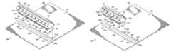
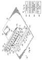
- FIG. 2 ais a perspective view illustrating an embodiment of a large card connector.
- FIG. 2 bis a bottom view illustrating an embodiment of the large card connector of FIG. 2 a.
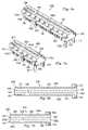
- FIG. 3 ais a perspective view illustrating an embodiment of a small card connector.
- FIG. 3 bis a bottom view illustrating an embodiment of the small card connector of FIG. 3 a.
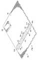
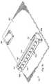
- FIG. 4is a perspective view illustrating an embodiment of a board used with the large card connector of FIG. 2 a and the small card connector of FIG. 3 a.
- FIG. 5 ais a flow chart illustrating an embodiment of a method for mounting a card connector using the large card connector of FIG. 2 a , the small card connector for FIG. 3 a , and the board of FIG. 4 .
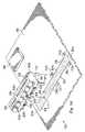
- FIG. 5 bis a perspective view illustrating an embodiment of the large card connector of FIG. 2 a being mounted to the board of FIG. 4 during the method of FIG. 5 a.
- FIG. 5 cis a perspective view illustrating an embodiment of the large card connector of FIG. 2 a mounted to the board of FIG. 4 using the method of FIG. 5 a.
- FIG. 5 dis a perspective view illustrating an embodiment of the small card connector of FIG. 3 a being mounted to the board of FIG. 4 during the method of FIG. 5 a.
- FIG. 5 eis a perspective view illustrating an embodiment of the small card connector of FIG. 3 a mounted to the board of FIG. 4 using the method of FIG. 5 a.
- FIG. 6 ais a perspective view illustrating an embodiment of a large card connector.
- FIG. 6 bis a bottom view illustrating an embodiment of the large card connector of FIG. 6 a.
- FIG. 7 ais a perspective view illustrating an embodiment of a small card connector.
- FIG. 7 bis a bottom view illustrating an embodiment of the small card connector of FIG. 3 a.
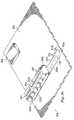
- FIG. 8is a perspective view illustrating an embodiment of a board used with the large card connector of FIG. 6 a and the small card connector of FIG. 7 a.
- FIG. 9 ais a flow chart illustrating an embodiment of a method for mounting a card connector using the large card connector of FIG. 6 a , the small card connector for FIG. 7 a , and the board of FIG. 8 .
- FIG. 9 bis a perspective view illustrating an embodiment of the large card connector of FIG. 6 a being mounted to the board of FIG. 8 during the method of FIG. 9 a.
- FIG. 9 cis a perspective view illustrating an embodiment of the large card connector of FIG. 6 a mounted to the board of FIG. 8 using the method of FIG. 9 a.
- FIG. 9 dis a perspective view illustrating an embodiment of the small card connector of FIG. 7 a being mounted to the board of FIG. 8 during the method of FIG. 9 a.
- FIG. 9 eis a perspective view illustrating an embodiment of the small card connector of FIG. 7 a mounted to the board of FIG. 8 using the method of FIG. 9 a.
- FIG. 10is a perspective view illustrating an alternative embodiment of a board.
- an information handling systemmay include any instrumentality or aggregate of instrumentalities operable to compute, classify, process, transmit, receive, retrieve, originate, switch, store, display, manifest, detect, record, reproduce, handle, or utilize any form of information, intelligence, or data for business, scientific, control, entertainment, or other purposes.
- an information handling systemmay be a personal computer, a PDA, a consumer electronic device, a network server or storage device, a switch router or other network communication device, or any other suitable device and may vary in size, shape, performance, functionality, and price.
- the information handling systemmay include memory, one or more processing resources such as a central processing unit (CPU) or hardware or software control logic.
- CPUcentral processing unit
- Additional components of the information handling systemmay include one or more storage devices, one or more communications ports for communicating with external devices as well as various input and output (I/O) devices, such as a keyboard, a mouse, and a video display.
- the information handling systemmay also include one or more buses operable to transmit communications between the various hardware components.
- information handling system 10includes a microprocessor 12 , which is connected to a bus 14 .
- Bus 14serves as a connection between microprocessor 12 and other components of computer system 10 .
- An input device 16is coupled to microprocessor 12 to provide input to microprocessor 12 . Examples of input devices include keyboards, touchscreens, and pointing devices such as mouses, trackballs and trackpads.
- Programs and dataare stored on a mass storage device 18 , which is coupled to microprocessor 12 .
- Mass storage devicesinclude such devices as hard disks, optical disks, magneto-optical drives, floppy drives and the like.
- Computer system 10further includes a display 20 , which is coupled to microprocessor 12 by a video controller 22 .
- a system memory 24is coupled to microprocessor 12 to provide the microprocessor with fast storage to facilitate execution of computer programs by microprocessor 12 .
- a chassis 26may house some or all of the components of information handling system 10 . It should be understood that other busses and intermediate circuits can be deployed between the components described above and microprocessor 12 to facilitate interconnection between the components and the microprocessor.
- Large card connector 100includes a base 102 having a first base end 102 a , a second base end 102 b positioned opposite the first base end 102 a , a first base side 102 c located along the length of the base 102 , a second base side 102 d located along the length of the base 102 and positioned opposite the first base side 102 c , a top base surface 102 e , and a bottom base surface 102 f positioned opposite the top base surface 102 e and bounded by the first base end 102 a , the second base end 102 b , the first base side 102 c , and the second base side 102 d .
- the base 102defines a card coupler slot 104 on the top base surface 102 e and along the length of the base 102 .
- a plurality of electrical coupling members 106extend from the bottom base surface 102 f and along the length of the base 102 .
- a board mounting member 108extends from the bottom base surface 102 f , is positioned between the first base side 102 c and the second base side 102 d , and is located between the electrical coupling members 106 and adjacent the second base end 102 b .
- a board mounting member 110extends from the first base side 102 c away from the base 102 and then down past the bottom base surface 102 f , and is positioned adjacent the bottom base surface 102 f and the first base end 102 a .
- the card connector 100includes a ⁇ 64 PCI-Express connector. In an exemplary embodiment, the card connector 100 includes a ⁇ 32 PCI-Express connector. In an exemplary embodiment, the card connector 100 includes a ⁇ 16 PCI-Express connector. In an exemplary embodiment, the card connector 100 includes a ⁇ 8 PCI-Express connector. In an exemplary embodiment, the card connector 100 includes a ⁇ 4 PCI-Express connector. In an exemplary embodiment, the card connector 100 includes a ⁇ 1 PCI-Express connector.
- Small card connector 200includes a base 202 having a first base end 202 a , a second base end 202 b positioned opposite the first base end 202 a , a first base side 202 c located along the length of the base 202 , a second base side 202 d located along the length of the base 202 and positioned opposite the first base side 202 c , a top base surface 202 e , and a bottom base surface 202 f positioned opposite the top base surface 202 e and bounded by the first base end 202 a , the second base end 202 b , the first base side 202 c , and the second base side 202 d .
- the base 202defines a card coupler slot 204 on the top base surface 202 e and along the length of the base 202 .
- a plurality of electrical coupling members 206extend from the bottom base surface 202 f and along the length of the base 202 .
- a board mounting member 208extends from the bottom base surface 202 f , is positioned between the first base side 202 c and the second base side 202 d , and is located between the electrical coupling members 206 and adjacent the second base end 202 b .
- a board mounting member 210extends from the first base side 202 c away from the base 202 and then down past the bottom base surface 202 f , and is positioned adjacent the bottom base surface 202 f and the first base end 202 a .
- the card connector 200includes a ⁇ 64 PCI-Express connector. In an exemplary embodiment, the card connector 200 includes a ⁇ 32 PCI-Express connector. In an exemplary embodiment, the card connector 200 includes a ⁇ 16 PCI-Express connector. In an exemplary embodiment, the card connector 200 includes a ⁇ 8 PCI-Express connector. In an exemplary embodiment, the card connector 200 includes a ⁇ 4 PCI-Express connector. In an exemplary embodiment, the card connector 200 includes a ⁇ 1 PCI-Express connector.
- Board 300includes a board surface 302 including a connector coupling section 304 .
- Connector coupling section 304includes a first section end 304 a , a second section end 304 b positioned opposite the first section end 304 a , a first section side 304 c located along the length of the connector coupling section 304 , and a second section side 304 d located along the length of the connector coupling section 304 and positioned opposite the first section side 304 c .
- a plurality of electrical connector couplers 306define the connector coupling section 304 and are bounded by the first section end 304 a , the second section end 304 b , the first section side 304 c , and the second section side 304 d .
- the electrical connector couplers 306are electrically coupled to an information handling system component 308 which is mounted to the board surface 302 .
- the information handling system component 308includes a chip set coupled to a microprocessor which may be, for example, the microprocessor 12 of information handling system 10 , described above with reference to FIG. 1 .
- a connector mounting member 310is defined by the board 300 , located on the board surface 302 in the connector coupling section 304 , and positioned between the first section side 304 c and the second section side 304 d , between the plurality of electrical connector couplers 306 , and adjacent the second section end 304 b .
- a plurality of connector coupling members 312 a and 312 bare defined by the board 300 , located on the board surface 302 and outside the connector coupling section 304 , and positioned in a spaced apart relationship adjacent the first section side 304 c .
- connector coupling member 312 ais positioned adjacent the first section end 304 a and connector coupling member 312 b is positioned substantially midway between the first section end 304 a and the second section end 304 b .
- the board 300may be mounted in the chassis 26 , described above with reference to FIG. 1 , and may include one of more of the components of information handling system 10 .
- Method 400begins at step 402 where the board 300 , illustrated in FIG. 4 , is provided.
- Board 300may be mounted in a chassis such as, for example, the chassis 26 illustrated in FIG. 1 , and may include components of an information handling system such as, for example, the information handling system 10 illustrated in FIG. 1 .
- the method 400then proceeds to step 404 where the card connector 100 and the card connector 200 , illustrated in FIGS. 2 a and 3 a , are provided.
- Card connector 100 and card connector 200are different size card connectors and, in an embodiment, may include a ⁇ 16 PCI-Express connector and a ⁇ 8 PCI-Express connector, respectively.
- the method 400proceeds to step 406 where a desired card connector size is determined.
- the determination of the desired card connector sizewill depend on the bandwidth needed for the card to be coupled to the board 300 . In an embodiment, a relatively larger bandwidth will be needed for the card, and the card connector 100 will be determined to be the appropriate sized card connector.
- the method 400then proceeds to step 408 where card connector 100 is mounted and electrically coupled to the board 300 .
- the card connector 100is positioned over the connector coupling section 304 on the board surface 302 such that first base end 102 a is lined up with first section end 304 a , second base end 102 b is lined up with second section end 304 b , first base side 102 c is lined up with first section side 304 c , second base side 102 d is lined up with second section side 304 d , board mounting member 108 is lined up with connector coupling member 310 , and board mounting member 110 is lined up with connector coupling member 312 a .
- the card connector 100may then be lowered onto the base 300 such that board mounting member 108 engages connector coupling member 310 and board mounting member 110 engages connector coupling member 312 a , resulting in the mounting of the card connector 100 to the board 300 .
- the electrical coupling members 106may then be electrically coupled to the electrical connector couplers 306 using methods known in the art such as, for example, soldering, resulting in the electrical coupling of the card connector 100 to the board 300 .
- the electrical coupling of the card connector 100 to the board 300electrically couples the card connector 100 to the information handling system component 308 .
- a relatively smaller bandwidthwill be needed for the card, and the card connector 200 will be determined to be the appropriate sized card connector.
- the method 400then proceeds to step 408 where card connector 200 is mounted and electrically coupled to the board 300 .
- the card connector 200is positioned over the connector coupling section 304 on the board surface 302 such that second base end 202 b is lined up with second section end 304 b , first base side 202 c is lined up with first section side 304 c , second base side 202 d is lined up with second section side 304 d , board mounting member 208 is lined up with connector coupling member 310 , and board mounting member 210 is lined up with connector coupling member 312 b .
- the card connector 200may then be lowered onto the base 300 such that board mounting member 208 engages connector coupling member 310 and board mounting member 210 engages connector coupling member 312 b , resulting in the mounting of the card connector 200 to the board 300 .
- the electrical coupling members 206may then be electrically coupled to the electrical connector couplers 306 using methods known in the art such as, for example, soldering, resulting in the electrical coupling of the card connector 200 to the board 300 .
- the electrical coupling of the card connector 200 to the board 300electrically couples the card connector 200 to the information handling system component 308 .
- the card connector 100 , card connector 200 , and board 300provide a card connector mounting system.
- a card connector mounting systemis provided which allows a plurality of different sized card connectors such as, for example, the card connectors 100 and 200 , to be connected to the same connector coupling section such as, for example, the connector coupling section 304 .
- the plurality of different sized card connectorsmay include ⁇ 1 PCI-Express connectors, ⁇ 2 PCI-Express connectors, ⁇ 4 PCI-Express connectors, ⁇ 8 PCI-Express connectors, ⁇ 12 PCI-Express connectors, ⁇ 16 PCI-Express connectors, ⁇ 32 PCI-Express connectors, ⁇ 64 PCI-Express connectors, and a variety of other card connectors known in the art.
- a large card connector 500is substantially similar to the large card connector 100 , described above with reference to FIGS. 2 a and 2 b , with the provision of a board mounting member 502 extending from the second base side 102 d away from the base 102 and then down past the bottom base surface 102 f , and positioned opposite the board mounting member 110 and adjacent the bottom base surface 102 f and the first base end 102 a .
- the card connector 500includes a ⁇ 64 PCI-Express connector.
- the card connector 500includes a ⁇ 32 PCI-Express connector.
- the card connector 500includes a ⁇ 16 PCI-Express connector. In an exemplary embodiment, the card connector 500 includes a ⁇ 8 PCI-Express connector. In an exemplary embodiment, the card connector 500 includes a ⁇ 4 PCI-Express connector. In an exemplary embodiment, the card connector 500 includes a ⁇ 1 PCI-Express connector.
- a small card connector 600is substantially similar in design and operation to the small card connector 200 , described above with reference to FIGS. 3 a and 3 b , with the provision of a board mounting member 602 extending from the second base side 202 c away from the base 202 and then down past the bottom base surface 202 f , and positioned opposite the board mounting member 210 and adjacent the bottom base surface 202 f and the first base end 202 a .
- the card connector 600includes a ⁇ 64 PCI-Express connector.
- the card connector 600includes a ⁇ 32 PCI-Express connector.
- the card connector 600includes a ⁇ 16 PCI-Express connector. In an exemplary embodiment, the card connector 600 includes a ⁇ 8 PCI-Express connector. In an exemplary embodiment, the card connector 600 includes a ⁇ 4 PCI-Express connector. In an exemplary embodiment, the card connector 600 includes a ⁇ 1 PCI-Express connector.
- a board 700is substantially similar in design and operation to the board 300 , described above with reference to FIG. 4 , with the provision of a plurality of connector coupling members 702 a and 702 b defined by the board 700 , located on the board surface 302 and outside the connector coupling section 304 , and positioned in a spaced apart relationship adjacent the second section side 304 d and opposite the connector coupling members 312 a and 312 b , respectively.
- connector coupling member 702 ais positioned adjacent the first section end 304 a and connector coupling member 702 b is positioned substantially midway between the first section end 304 a and the second section end 304 b .
- the board 700may be mounted in the chassis 26 , described above with reference to FIG. 1 , and may include one of more of the components of information handling system 10 .
- Method 800begins at step 802 where the board 700 , illustrated in FIG. 8 , is provided.
- Board 700may be mounted in a chassis such as, for example, the chassis 26 illustrated in FIG. 1 , and may include components of an information handling system such as, for example, the information handling system 10 illustrated in FIG. 1 .
- the method 800then proceeds to step 804 where the card connector 500 and the card connector 600 , illustrated in FIGS. 6 a and 7 a , are provided.
- Card connector 500 and card connector 600are different size card connectors and, in an embodiment, may include a ⁇ 16 PCI-Express connector and a ⁇ 8 PCI-Express connector, respectively.
- the method 800proceeds to step 806 where a desired card connector size is determined.
- the determination of the desired card connector sizewill depend on the bandwidth needed for the card to be coupled to the board 700 . In an embodiment, a relatively larger bandwidth will be needed for the card, and the card connector 500 will be determined to be the appropriate sized card connector.
- the method 700then proceeds to step 808 where card connector 500 is mounted and electrically coupled to the board 700 .
- the card connector 500is positioned over the connector coupling section 304 on the board surface 302 such that first base end 102 a is lined up with first section end 304 a , second base end 102 b is lined up with second section end 304 b , first base side 102 c is lined up with first section side 304 c , second base side 102 d is lined up with second section side 304 d , board mounting member 108 is lined up with connector coupling member 310 , board mounting member 110 is lined up with connector coupling member 312 a , and board mounting member 502 is lined up with connector coupling member 702 a .
- the card connector 500may then be lowered onto the base 700 such that board mounting member 108 engages connector coupling member 310 , board mounting member 110 engages connector coupling member 312 a , and board mounting member 502 engages connector coupling member 702 a , resulting in the mounting of the card connector 500 to the board 700 .
- the electrical coupling members 106may then be electrically coupled to the electrical connector couplers 306 using methods known in the art such as, for example, soldering, resulting in the electrical coupling of the card connector 500 to the board 700 .
- the electrical coupling of the card connector 500 to the board 700electrically couples the card connector 500 to the information handling system component 308 .
- a relatively smaller bandwidthwill be needed for the card, and the card connector 600 will be determined to be the appropriate sized card connector.
- the method 800then proceeds to step 808 where card connector 600 is mounted and electrically coupled to the board 700 .
- the card connector 600is positioned over the connector coupling section 304 on the board surface 302 such that second base end 202 b is lined up with second section end 304 b , first base side 202 c is lined up with first section side 304 c , second base side 202 d is lined up with second section side 304 d , board mounting member 208 is lined up with connector coupling member 310 , board mounting member 210 is lined up with connector coupling member 312 b , and board mounting member 602 is lined up with connector coupling member 702 b .
- the card connector 600may then be lowered onto the base 700 such that board mounting member 208 engages connector coupling member 310 , board mounting member 210 engages connector coupling member 312 b , and board mounting member 602 engages connector coupling member 702 b , resulting in the mounting of the card connector 600 to the board 700 .
- the electrical coupling members 206may then be electrically coupled to the electrical connector couplers 306 using methods known in the art such as, for example, soldering, resulting in the electrical coupling of the card connector 600 to the board 700 .
- the electrical coupling of the card connector 600 to the board 700electrically couples the card connector 600 to the information handling system component 308 .
- the card connector 500 , card connector 600 , and board 700provide a card connector mounting system.
- a card connector mounting systemis provided which allows a plurality of different sized card connectors such as, for example, the card connectors 500 and 600 , to be connected to the same connector coupling section such as, for example, the connector coupling section 304 .
- the plurality of different sized card connectorsmay include ⁇ 1 PCI-Express connectors, ⁇ 2 PCI-Express connectors, ⁇ 4 PCI-Express connectors, ⁇ 8 PCI-Express connectors, ⁇ 12 PCI-Express connectors, ⁇ 16 PCI-Express connectors, ⁇ 32 PCI-Express connectors, ⁇ 64 PCI-Express connectors, and a variety of other card connectors known in the art.
- a board 900is substantially similar in design and operation to the board 700 , described above with reference to FIG. 8 , with the provision of a plurality of connector coupling members 902 a and 902 b defined by the board 900 , located on the board surface 302 and outside the connector coupling section 304 , and positioned in a spaced apart relationship adjacent the first section side 304 c and between the connector coupling member 312 b and the second section end 304 b .
- a plurality of connector coupling members 904 a and 904 bare also defined by the board 900 , located on the board surface 302 and outside the connector coupling section 304 , and positioned in a spaced apart relationship adjacent the second section side 304 d , between the connector coupling member 702 b and the second section end 304 b , and opposite the connector coupling members 902 a and 902 b , respectively.
- the board mounting members 310 , 312 a and 702 a , 312 b and 702 b , 902 a and 904 a , and 902 b and 904 bmay be used to mount a plurality of different sized card connectors to the connector coupling section 604 on the board 900 in substantially the same manner as described above in methods 400 and 800 .
- additional connector coupling membersmay be added to the board to allow additional sizes of card connectors to be coupled to the connector coupling section 604 on the board 900 .
Landscapes
- Engineering & Computer Science (AREA)
- Manufacturing & Machinery (AREA)
- Coupling Device And Connection With Printed Circuit (AREA)
Abstract
Description
Claims (7)
Priority Applications (1)
| Application Number | Priority Date | Filing Date | Title |
|---|---|---|---|
| US11/096,027US7083423B1 (en) | 2005-03-31 | 2005-03-31 | Method and apparatus for mounting a card connector |
Applications Claiming Priority (1)
| Application Number | Priority Date | Filing Date | Title |
|---|---|---|---|
| US11/096,027US7083423B1 (en) | 2005-03-31 | 2005-03-31 | Method and apparatus for mounting a card connector |
Publications (1)
| Publication Number | Publication Date |
|---|---|
| US7083423B1true US7083423B1 (en) | 2006-08-01 |
Family
ID=36710449
Family Applications (1)
| Application Number | Title | Priority Date | Filing Date |
|---|---|---|---|
| US11/096,027Expired - LifetimeUS7083423B1 (en) | 2005-03-31 | 2005-03-31 | Method and apparatus for mounting a card connector |
Country Status (1)
| Country | Link |
|---|---|
| US (1) | US7083423B1 (en) |
Cited By (7)
| Publication number | Priority date | Publication date | Assignee | Title |
|---|---|---|---|---|
| US20070170936A1 (en)* | 2006-01-24 | 2007-07-26 | Glenn Wood | Regenerator probe |
| US20070236458A1 (en)* | 2006-03-29 | 2007-10-11 | Dell Products L.P. | Method and apparatus for coupling a display to an information handling system |
| US20110016252A1 (en)* | 2009-07-17 | 2011-01-20 | Dell Products, Lp | Multiple Minicard Interface System and Method Thereof |
| US20130046914A1 (en)* | 2011-08-17 | 2013-02-21 | Hon Hai Precision Industry Co., Ltd. | Connector assembly |
| US20130252449A1 (en)* | 2012-03-20 | 2013-09-26 | Hon Hai Precision Industry Co., Ltd. | Card edge connector |
| US20130288502A1 (en)* | 2012-04-27 | 2013-10-31 | International Business Machines Corporation | Memory module connector with air deflection system |
| US20160336665A1 (en)* | 2015-05-13 | 2016-11-17 | Giga-Byte Technology Co., Ltd. | Pci-e connector cover and pci-e connector module |
Citations (4)
| Publication number | Priority date | Publication date | Assignee | Title |
|---|---|---|---|---|
| US5961352A (en)* | 1996-11-15 | 1999-10-05 | International Business Machines Corporation | Shared card slots for PCI and ISA adapter cards |
| US6152742A (en)* | 1995-05-31 | 2000-11-28 | Teradyne, Inc. | Surface mounted electrical connector |
| US6655976B1 (en)* | 2002-11-26 | 2003-12-02 | Hon Hai Precision Ind. Co., Ltd. | Electrical connector |
| US6824407B1 (en)* | 2003-06-03 | 2004-11-30 | Hon Hai Precision Ind. Co., Ltd. | Card edge connector with latch |
- 2005
- 2005-03-31USUS11/096,027patent/US7083423B1/ennot_activeExpired - Lifetime
Patent Citations (4)
| Publication number | Priority date | Publication date | Assignee | Title |
|---|---|---|---|---|
| US6152742A (en)* | 1995-05-31 | 2000-11-28 | Teradyne, Inc. | Surface mounted electrical connector |
| US5961352A (en)* | 1996-11-15 | 1999-10-05 | International Business Machines Corporation | Shared card slots for PCI and ISA adapter cards |
| US6655976B1 (en)* | 2002-11-26 | 2003-12-02 | Hon Hai Precision Ind. Co., Ltd. | Electrical connector |
| US6824407B1 (en)* | 2003-06-03 | 2004-11-30 | Hon Hai Precision Ind. Co., Ltd. | Card edge connector with latch |
Cited By (13)
| Publication number | Priority date | Publication date | Assignee | Title |
|---|---|---|---|---|
| US20070170936A1 (en)* | 2006-01-24 | 2007-07-26 | Glenn Wood | Regenerator probe |
| US7282935B2 (en)* | 2006-01-24 | 2007-10-16 | Agilent Technologies, Inc. | Regenerator probe |
| US20070236458A1 (en)* | 2006-03-29 | 2007-10-11 | Dell Products L.P. | Method and apparatus for coupling a display to an information handling system |
| US8144119B2 (en)* | 2006-03-29 | 2012-03-27 | Dell Products L.P. | Method and apparatus for coupling a display to an information handling system |
| US20110016252A1 (en)* | 2009-07-17 | 2011-01-20 | Dell Products, Lp | Multiple Minicard Interface System and Method Thereof |
| US7996596B2 (en) | 2009-07-17 | 2011-08-09 | Dell Products, Lp | Multiple minicard interface system and method thereof |
| US20130046914A1 (en)* | 2011-08-17 | 2013-02-21 | Hon Hai Precision Industry Co., Ltd. | Connector assembly |
| US20130252449A1 (en)* | 2012-03-20 | 2013-09-26 | Hon Hai Precision Industry Co., Ltd. | Card edge connector |
| US9022809B2 (en)* | 2012-03-20 | 2015-05-05 | Hon Hai Precision Industry Co., Ltd. | Card edge connector |
| US20130288502A1 (en)* | 2012-04-27 | 2013-10-31 | International Business Machines Corporation | Memory module connector with air deflection system |
| US8684757B2 (en)* | 2012-04-27 | 2014-04-01 | International Business Machines Corporation | Memory module connector with air deflection system |
| US20160336665A1 (en)* | 2015-05-13 | 2016-11-17 | Giga-Byte Technology Co., Ltd. | Pci-e connector cover and pci-e connector module |
| US9570823B2 (en)* | 2015-05-13 | 2017-02-14 | Giga Byte Technology Co., Ltd. | PCI-E connector cover and PCI-E connector module |
Similar Documents
| Publication | Publication Date | Title |
|---|---|---|
| US7440293B2 (en) | Method and apparatus for mounting a card in an information handling system | |
| US7672141B2 (en) | Alignment and support apparatus for component and card coupling | |
| US8514585B2 (en) | Electronic device | |
| US11093010B2 (en) | Expansion module system | |
| US20080168204A1 (en) | Information Handling System Card | |
| US7580260B2 (en) | Coupling for a fan bay including fans with a chassis | |
| US7460365B2 (en) | Interposer for a drive bay | |
| US7465189B2 (en) | Method and apparatus for electrically coupling a component to an information handling system | |
| US9521757B2 (en) | Systems and methods for loading of a component | |
| US20060215367A1 (en) | Method and apparatus for thermal dissipation in an information handling system | |
| US7272017B2 (en) | Method and apparatus for coupling a plurality of cards to an information handling system | |
| US11074952B1 (en) | System and method for compression Dual In-Line Memory Module reversibility | |
| US7515438B2 (en) | Systems and methods for implementing subcriber identity modules | |
| US12288595B2 (en) | System and method for providing compression attached memory module compression connectors | |
| US7278872B2 (en) | Method and apparatus for retaining a card in an information handling system | |
| US7716408B2 (en) | Burn rack docking apparatus for an information handling system | |
| US7083423B1 (en) | Method and apparatus for mounting a card connector | |
| US12183717B2 (en) | System and method for stacking compression attached memory modules | |
| US20040066620A1 (en) | Device to allow computers to adapt to multiple docking stations | |
| US7305509B2 (en) | Method and apparatus for zero stub serial termination capacitor of resistor mounting option in an information handling system | |
| US20220350754A1 (en) | Compression attached memory module for offset stacking | |
| US20070300003A1 (en) | Method and apparatus for increasing the performance of a portable information handling system | |
| US9350098B2 (en) | Systems and methods for stacking compression connectors | |
| US20060259918A1 (en) | Method and apparatus for mounting a storage device in an information handling system | |
| US20070236458A1 (en) | Method and apparatus for coupling a display to an information handling system |
Legal Events
| Date | Code | Title | Description |
|---|---|---|---|
| AS | Assignment | Owner name:DELL PRODUCTS L.P., TEXAS Free format text:ASSIGNMENT OF ASSIGNORS INTEREST;ASSIGNORS:GUERRA, JR., WILLIAM M;STUEWE, JOHN;REEL/FRAME:016475/0260 Effective date:20050329 | |
| FEPP | Fee payment procedure | Free format text:PAYOR NUMBER ASSIGNED (ORIGINAL EVENT CODE: ASPN); ENTITY STATUS OF PATENT OWNER: LARGE ENTITY | |
| STCF | Information on status: patent grant | Free format text:PATENTED CASE | |
| FPAY | Fee payment | Year of fee payment:4 | |
| AS | Assignment | Owner name:BANK OF AMERICA, N.A., AS COLLATERAL AGENT, NORTH CAROLINA Free format text:PATENT SECURITY AGREEMENT (TERM LOAN);ASSIGNORS:DELL INC.;APPASSURE SOFTWARE, INC.;ASAP SOFTWARE EXPRESS, INC.;AND OTHERS;REEL/FRAME:031899/0261 Effective date:20131029 Owner name:BANK OF AMERICA, N.A., AS ADMINISTRATIVE AGENT, TEXAS Free format text:PATENT SECURITY AGREEMENT (ABL);ASSIGNORS:DELL INC.;APPASSURE SOFTWARE, INC.;ASAP SOFTWARE EXPRESS, INC.;AND OTHERS;REEL/FRAME:031898/0001 Effective date:20131029 Owner name:BANK OF NEW YORK MELLON TRUST COMPANY, N.A., AS FIRST LIEN COLLATERAL AGENT, TEXAS Free format text:PATENT SECURITY AGREEMENT (NOTES);ASSIGNORS:APPASSURE SOFTWARE, INC.;ASAP SOFTWARE EXPRESS, INC.;BOOMI, INC.;AND OTHERS;REEL/FRAME:031897/0348 Effective date:20131029 Owner name:BANK OF NEW YORK MELLON TRUST COMPANY, N.A., AS FI Free format text:PATENT SECURITY AGREEMENT (NOTES);ASSIGNORS:APPASSURE SOFTWARE, INC.;ASAP SOFTWARE EXPRESS, INC.;BOOMI, INC.;AND OTHERS;REEL/FRAME:031897/0348 Effective date:20131029 Owner name:BANK OF AMERICA, N.A., AS COLLATERAL AGENT, NORTH Free format text:PATENT SECURITY AGREEMENT (TERM LOAN);ASSIGNORS:DELL INC.;APPASSURE SOFTWARE, INC.;ASAP SOFTWARE EXPRESS, INC.;AND OTHERS;REEL/FRAME:031899/0261 Effective date:20131029 Owner name:BANK OF AMERICA, N.A., AS ADMINISTRATIVE AGENT, TE Free format text:PATENT SECURITY AGREEMENT (ABL);ASSIGNORS:DELL INC.;APPASSURE SOFTWARE, INC.;ASAP SOFTWARE EXPRESS, INC.;AND OTHERS;REEL/FRAME:031898/0001 Effective date:20131029 | |
| FPAY | Fee payment | Year of fee payment:8 | |
| AS | Assignment | Owner name:DELL USA L.P., TEXAS Free format text:RELEASE BY SECURED PARTY;ASSIGNOR:BANK OF AMERICA, N.A., AS ADMINISTRATIVE AGENT;REEL/FRAME:040065/0216 Effective date:20160907 Owner name:SECUREWORKS, INC., GEORGIA Free format text:RELEASE BY SECURED PARTY;ASSIGNOR:BANK OF AMERICA, N.A., AS ADMINISTRATIVE AGENT;REEL/FRAME:040065/0216 Effective date:20160907 Owner name:DELL MARKETING L.P., TEXAS Free format text:RELEASE BY SECURED PARTY;ASSIGNOR:BANK OF AMERICA, N.A., AS ADMINISTRATIVE AGENT;REEL/FRAME:040065/0216 Effective date:20160907 Owner name:WYSE TECHNOLOGY L.L.C., CALIFORNIA Free format text:RELEASE BY SECURED PARTY;ASSIGNOR:BANK OF AMERICA, N.A., AS ADMINISTRATIVE AGENT;REEL/FRAME:040065/0216 Effective date:20160907 Owner name:FORCE10 NETWORKS, INC., CALIFORNIA Free format text:RELEASE BY SECURED PARTY;ASSIGNOR:BANK OF AMERICA, N.A., AS ADMINISTRATIVE AGENT;REEL/FRAME:040065/0216 Effective date:20160907 Owner name:PEROT SYSTEMS CORPORATION, TEXAS Free format text:RELEASE BY SECURED PARTY;ASSIGNOR:BANK OF AMERICA, N.A., AS ADMINISTRATIVE AGENT;REEL/FRAME:040065/0216 Effective date:20160907 Owner name:ASAP SOFTWARE EXPRESS, INC., ILLINOIS Free format text:RELEASE BY SECURED PARTY;ASSIGNOR:BANK OF AMERICA, N.A., AS ADMINISTRATIVE AGENT;REEL/FRAME:040065/0216 Effective date:20160907 Owner name:DELL PRODUCTS L.P., TEXAS Free format text:RELEASE BY SECURED PARTY;ASSIGNOR:BANK OF AMERICA, N.A., AS ADMINISTRATIVE AGENT;REEL/FRAME:040065/0216 Effective date:20160907 Owner name:DELL SOFTWARE INC., CALIFORNIA Free format text:RELEASE BY SECURED PARTY;ASSIGNOR:BANK OF AMERICA, N.A., AS ADMINISTRATIVE AGENT;REEL/FRAME:040065/0216 Effective date:20160907 Owner name:APPASSURE SOFTWARE, INC., VIRGINIA Free format text:RELEASE BY SECURED PARTY;ASSIGNOR:BANK OF AMERICA, N.A., AS ADMINISTRATIVE AGENT;REEL/FRAME:040065/0216 Effective date:20160907 Owner name:CREDANT TECHNOLOGIES, INC., TEXAS Free format text:RELEASE BY SECURED PARTY;ASSIGNOR:BANK OF AMERICA, N.A., AS ADMINISTRATIVE AGENT;REEL/FRAME:040065/0216 Effective date:20160907 Owner name:COMPELLANT TECHNOLOGIES, INC., MINNESOTA Free format text:RELEASE BY SECURED PARTY;ASSIGNOR:BANK OF AMERICA, N.A., AS ADMINISTRATIVE AGENT;REEL/FRAME:040065/0216 Effective date:20160907 Owner name:DELL INC., TEXAS Free format text:RELEASE BY SECURED PARTY;ASSIGNOR:BANK OF AMERICA, N.A., AS ADMINISTRATIVE AGENT;REEL/FRAME:040065/0216 Effective date:20160907 | |
| AS | Assignment | Owner name:COMPELLENT TECHNOLOGIES, INC., MINNESOTA Free format text:RELEASE BY SECURED PARTY;ASSIGNOR:BANK OF AMERICA, N.A., AS COLLATERAL AGENT;REEL/FRAME:040040/0001 Effective date:20160907 Owner name:FORCE10 NETWORKS, INC., CALIFORNIA Free format text:RELEASE BY SECURED PARTY;ASSIGNOR:BANK OF AMERICA, N.A., AS COLLATERAL AGENT;REEL/FRAME:040040/0001 Effective date:20160907 Owner name:ASAP SOFTWARE EXPRESS, INC., ILLINOIS Free format text:RELEASE BY SECURED PARTY;ASSIGNOR:BANK OF AMERICA, N.A., AS COLLATERAL AGENT;REEL/FRAME:040040/0001 Effective date:20160907 Owner name:APPASSURE SOFTWARE, INC., VIRGINIA Free format text:RELEASE BY SECURED PARTY;ASSIGNOR:BANK OF AMERICA, N.A., AS COLLATERAL AGENT;REEL/FRAME:040040/0001 Effective date:20160907 Owner name:DELL USA L.P., TEXAS Free format text:RELEASE BY SECURED PARTY;ASSIGNOR:BANK OF AMERICA, N.A., AS COLLATERAL AGENT;REEL/FRAME:040040/0001 Effective date:20160907 Owner name:DELL SOFTWARE INC., CALIFORNIA Free format text:RELEASE BY SECURED PARTY;ASSIGNOR:BANK OF AMERICA, N.A., AS COLLATERAL AGENT;REEL/FRAME:040040/0001 Effective date:20160907 Owner name:DELL MARKETING L.P., TEXAS Free format text:RELEASE BY SECURED PARTY;ASSIGNOR:BANK OF AMERICA, N.A., AS COLLATERAL AGENT;REEL/FRAME:040040/0001 Effective date:20160907 Owner name:CREDANT TECHNOLOGIES, INC., TEXAS Free format text:RELEASE BY SECURED PARTY;ASSIGNOR:BANK OF AMERICA, N.A., AS COLLATERAL AGENT;REEL/FRAME:040040/0001 Effective date:20160907 Owner name:DELL PRODUCTS L.P., TEXAS Free format text:RELEASE BY SECURED PARTY;ASSIGNOR:BANK OF AMERICA, N.A., AS COLLATERAL AGENT;REEL/FRAME:040040/0001 Effective date:20160907 Owner name:PEROT SYSTEMS CORPORATION, TEXAS Free format text:RELEASE BY SECURED PARTY;ASSIGNOR:BANK OF AMERICA, N.A., AS COLLATERAL AGENT;REEL/FRAME:040040/0001 Effective date:20160907 Owner name:WYSE TECHNOLOGY L.L.C., CALIFORNIA Free format text:RELEASE BY SECURED PARTY;ASSIGNOR:BANK OF AMERICA, N.A., AS COLLATERAL AGENT;REEL/FRAME:040040/0001 Effective date:20160907 Owner name:SECUREWORKS, INC., GEORGIA Free format text:RELEASE BY SECURED PARTY;ASSIGNOR:BANK OF AMERICA, N.A., AS COLLATERAL AGENT;REEL/FRAME:040040/0001 Effective date:20160907 Owner name:DELL INC., TEXAS Free format text:RELEASE BY SECURED PARTY;ASSIGNOR:BANK OF AMERICA, N.A., AS COLLATERAL AGENT;REEL/FRAME:040040/0001 Effective date:20160907 Owner name:SECUREWORKS, INC., GEORGIA Free format text:RELEASE BY SECURED PARTY;ASSIGNOR:BANK OF NEW YORK MELLON TRUST COMPANY, N.A., AS COLLATERAL AGENT;REEL/FRAME:040065/0618 Effective date:20160907 Owner name:DELL INC., TEXAS Free format text:RELEASE BY SECURED PARTY;ASSIGNOR:BANK OF NEW YORK MELLON TRUST COMPANY, N.A., AS COLLATERAL AGENT;REEL/FRAME:040065/0618 Effective date:20160907 Owner name:ASAP SOFTWARE EXPRESS, INC., ILLINOIS Free format text:RELEASE BY SECURED PARTY;ASSIGNOR:BANK OF NEW YORK MELLON TRUST COMPANY, N.A., AS COLLATERAL AGENT;REEL/FRAME:040065/0618 Effective date:20160907 Owner name:PEROT SYSTEMS CORPORATION, TEXAS Free format text:RELEASE BY SECURED PARTY;ASSIGNOR:BANK OF NEW YORK MELLON TRUST COMPANY, N.A., AS COLLATERAL AGENT;REEL/FRAME:040065/0618 Effective date:20160907 Owner name:DELL SOFTWARE INC., CALIFORNIA Free format text:RELEASE BY SECURED PARTY;ASSIGNOR:BANK OF NEW YORK MELLON TRUST COMPANY, N.A., AS COLLATERAL AGENT;REEL/FRAME:040065/0618 Effective date:20160907 Owner name:DELL USA L.P., TEXAS Free format text:RELEASE BY SECURED PARTY;ASSIGNOR:BANK OF NEW YORK MELLON TRUST COMPANY, N.A., AS COLLATERAL AGENT;REEL/FRAME:040065/0618 Effective date:20160907 Owner name:APPASSURE SOFTWARE, INC., VIRGINIA Free format text:RELEASE BY SECURED PARTY;ASSIGNOR:BANK OF NEW YORK MELLON TRUST COMPANY, N.A., AS COLLATERAL AGENT;REEL/FRAME:040065/0618 Effective date:20160907 Owner name:CREDANT TECHNOLOGIES, INC., TEXAS Free format text:RELEASE BY SECURED PARTY;ASSIGNOR:BANK OF NEW YORK MELLON TRUST COMPANY, N.A., AS COLLATERAL AGENT;REEL/FRAME:040065/0618 Effective date:20160907 Owner name:FORCE10 NETWORKS, INC., CALIFORNIA Free format text:RELEASE BY SECURED PARTY;ASSIGNOR:BANK OF NEW YORK MELLON TRUST COMPANY, N.A., AS COLLATERAL AGENT;REEL/FRAME:040065/0618 Effective date:20160907 Owner name:COMPELLENT TECHNOLOGIES, INC., MINNESOTA Free format text:RELEASE BY SECURED PARTY;ASSIGNOR:BANK OF NEW YORK MELLON TRUST COMPANY, N.A., AS COLLATERAL AGENT;REEL/FRAME:040065/0618 Effective date:20160907 Owner name:WYSE TECHNOLOGY L.L.C., CALIFORNIA Free format text:RELEASE BY SECURED PARTY;ASSIGNOR:BANK OF NEW YORK MELLON TRUST COMPANY, N.A., AS COLLATERAL AGENT;REEL/FRAME:040065/0618 Effective date:20160907 Owner name:DELL PRODUCTS L.P., TEXAS Free format text:RELEASE BY SECURED PARTY;ASSIGNOR:BANK OF NEW YORK MELLON TRUST COMPANY, N.A., AS COLLATERAL AGENT;REEL/FRAME:040065/0618 Effective date:20160907 Owner name:DELL MARKETING L.P., TEXAS Free format text:RELEASE BY SECURED PARTY;ASSIGNOR:BANK OF NEW YORK MELLON TRUST COMPANY, N.A., AS COLLATERAL AGENT;REEL/FRAME:040065/0618 Effective date:20160907 | |
| AS | Assignment | Owner name:THE BANK OF NEW YORK MELLON TRUST COMPANY, N.A., AS NOTES COLLATERAL AGENT, TEXAS Free format text:SECURITY AGREEMENT;ASSIGNORS:ASAP SOFTWARE EXPRESS, INC.;AVENTAIL LLC;CREDANT TECHNOLOGIES, INC.;AND OTHERS;REEL/FRAME:040136/0001 Effective date:20160907 Owner name:CREDIT SUISSE AG, CAYMAN ISLANDS BRANCH, AS COLLATERAL AGENT, NORTH CAROLINA Free format text:SECURITY AGREEMENT;ASSIGNORS:ASAP SOFTWARE EXPRESS, INC.;AVENTAIL LLC;CREDANT TECHNOLOGIES, INC.;AND OTHERS;REEL/FRAME:040134/0001 Effective date:20160907 Owner name:CREDIT SUISSE AG, CAYMAN ISLANDS BRANCH, AS COLLAT Free format text:SECURITY AGREEMENT;ASSIGNORS:ASAP SOFTWARE EXPRESS, INC.;AVENTAIL LLC;CREDANT TECHNOLOGIES, INC.;AND OTHERS;REEL/FRAME:040134/0001 Effective date:20160907 Owner name:THE BANK OF NEW YORK MELLON TRUST COMPANY, N.A., A Free format text:SECURITY AGREEMENT;ASSIGNORS:ASAP SOFTWARE EXPRESS, INC.;AVENTAIL LLC;CREDANT TECHNOLOGIES, INC.;AND OTHERS;REEL/FRAME:040136/0001 Effective date:20160907 | |
| MAFP | Maintenance fee payment | Free format text:PAYMENT OF MAINTENANCE FEE, 12TH YEAR, LARGE ENTITY (ORIGINAL EVENT CODE: M1553) Year of fee payment:12 | |
| AS | Assignment | Owner name:THE BANK OF NEW YORK MELLON TRUST COMPANY, N.A., T Free format text:SECURITY AGREEMENT;ASSIGNORS:CREDANT TECHNOLOGIES, INC.;DELL INTERNATIONAL L.L.C.;DELL MARKETING L.P.;AND OTHERS;REEL/FRAME:049452/0223 Effective date:20190320 Owner name:THE BANK OF NEW YORK MELLON TRUST COMPANY, N.A., TEXAS Free format text:SECURITY AGREEMENT;ASSIGNORS:CREDANT TECHNOLOGIES, INC.;DELL INTERNATIONAL L.L.C.;DELL MARKETING L.P.;AND OTHERS;REEL/FRAME:049452/0223 Effective date:20190320 | |
| AS | Assignment | Owner name:THE BANK OF NEW YORK MELLON TRUST COMPANY, N.A., TEXAS Free format text:SECURITY AGREEMENT;ASSIGNORS:CREDANT TECHNOLOGIES INC.;DELL INTERNATIONAL L.L.C.;DELL MARKETING L.P.;AND OTHERS;REEL/FRAME:053546/0001 Effective date:20200409 | |
| AS | Assignment | Owner name:WYSE TECHNOLOGY L.L.C., CALIFORNIA Free format text:RELEASE BY SECURED PARTY;ASSIGNOR:CREDIT SUISSE AG, CAYMAN ISLANDS BRANCH;REEL/FRAME:058216/0001 Effective date:20211101 Owner name:SCALEIO LLC, MASSACHUSETTS Free format text:RELEASE BY SECURED PARTY;ASSIGNOR:CREDIT SUISSE AG, CAYMAN ISLANDS BRANCH;REEL/FRAME:058216/0001 Effective date:20211101 Owner name:MOZY, INC., WASHINGTON Free format text:RELEASE BY SECURED PARTY;ASSIGNOR:CREDIT SUISSE AG, CAYMAN ISLANDS BRANCH;REEL/FRAME:058216/0001 Effective date:20211101 Owner name:MAGINATICS LLC, CALIFORNIA Free format text:RELEASE BY SECURED PARTY;ASSIGNOR:CREDIT SUISSE AG, CAYMAN ISLANDS BRANCH;REEL/FRAME:058216/0001 Effective date:20211101 Owner name:FORCE10 NETWORKS, INC., CALIFORNIA Free format text:RELEASE BY SECURED PARTY;ASSIGNOR:CREDIT SUISSE AG, CAYMAN ISLANDS BRANCH;REEL/FRAME:058216/0001 Effective date:20211101 Owner name:EMC IP HOLDING COMPANY LLC, TEXAS Free format text:RELEASE BY SECURED PARTY;ASSIGNOR:CREDIT SUISSE AG, CAYMAN ISLANDS BRANCH;REEL/FRAME:058216/0001 Effective date:20211101 Owner name:EMC CORPORATION, MASSACHUSETTS Free format text:RELEASE BY SECURED PARTY;ASSIGNOR:CREDIT SUISSE AG, CAYMAN ISLANDS BRANCH;REEL/FRAME:058216/0001 Effective date:20211101 Owner name:DELL SYSTEMS CORPORATION, TEXAS Free format text:RELEASE BY SECURED PARTY;ASSIGNOR:CREDIT SUISSE AG, CAYMAN ISLANDS BRANCH;REEL/FRAME:058216/0001 Effective date:20211101 Owner name:DELL SOFTWARE INC., CALIFORNIA Free format text:RELEASE BY SECURED PARTY;ASSIGNOR:CREDIT SUISSE AG, CAYMAN ISLANDS BRANCH;REEL/FRAME:058216/0001 Effective date:20211101 Owner name:DELL PRODUCTS L.P., TEXAS Free format text:RELEASE BY SECURED PARTY;ASSIGNOR:CREDIT SUISSE AG, CAYMAN ISLANDS BRANCH;REEL/FRAME:058216/0001 Effective date:20211101 Owner name:DELL MARKETING L.P., TEXAS Free format text:RELEASE BY SECURED PARTY;ASSIGNOR:CREDIT SUISSE AG, CAYMAN ISLANDS BRANCH;REEL/FRAME:058216/0001 Effective date:20211101 Owner name:DELL INTERNATIONAL, L.L.C., TEXAS Free format text:RELEASE BY SECURED PARTY;ASSIGNOR:CREDIT SUISSE AG, CAYMAN ISLANDS BRANCH;REEL/FRAME:058216/0001 Effective date:20211101 Owner name:DELL USA L.P., TEXAS Free format text:RELEASE BY SECURED PARTY;ASSIGNOR:CREDIT SUISSE AG, CAYMAN ISLANDS BRANCH;REEL/FRAME:058216/0001 Effective date:20211101 Owner name:CREDANT TECHNOLOGIES, INC., TEXAS Free format text:RELEASE BY SECURED PARTY;ASSIGNOR:CREDIT SUISSE AG, CAYMAN ISLANDS BRANCH;REEL/FRAME:058216/0001 Effective date:20211101 Owner name:AVENTAIL LLC, CALIFORNIA Free format text:RELEASE BY SECURED PARTY;ASSIGNOR:CREDIT SUISSE AG, CAYMAN ISLANDS BRANCH;REEL/FRAME:058216/0001 Effective date:20211101 Owner name:ASAP SOFTWARE EXPRESS, INC., ILLINOIS Free format text:RELEASE BY SECURED PARTY;ASSIGNOR:CREDIT SUISSE AG, CAYMAN ISLANDS BRANCH;REEL/FRAME:058216/0001 Effective date:20211101 | |
| AS | Assignment | Owner name:SCALEIO LLC, MASSACHUSETTS Free format text:RELEASE OF SECURITY INTEREST IN PATENTS PREVIOUSLY RECORDED AT REEL/FRAME (040136/0001);ASSIGNOR:THE BANK OF NEW YORK MELLON TRUST COMPANY, N.A., AS NOTES COLLATERAL AGENT;REEL/FRAME:061324/0001 Effective date:20220329 Owner name:EMC IP HOLDING COMPANY LLC (ON BEHALF OF ITSELF AND AS SUCCESSOR-IN-INTEREST TO MOZY, INC.), TEXAS Free format text:RELEASE OF SECURITY INTEREST IN PATENTS PREVIOUSLY RECORDED AT REEL/FRAME (040136/0001);ASSIGNOR:THE BANK OF NEW YORK MELLON TRUST COMPANY, N.A., AS NOTES COLLATERAL AGENT;REEL/FRAME:061324/0001 Effective date:20220329 Owner name:EMC CORPORATION (ON BEHALF OF ITSELF AND AS SUCCESSOR-IN-INTEREST TO MAGINATICS LLC), MASSACHUSETTS Free format text:RELEASE OF SECURITY INTEREST IN PATENTS PREVIOUSLY RECORDED AT REEL/FRAME (040136/0001);ASSIGNOR:THE BANK OF NEW YORK MELLON TRUST COMPANY, N.A., AS NOTES COLLATERAL AGENT;REEL/FRAME:061324/0001 Effective date:20220329 Owner name:DELL MARKETING CORPORATION (SUCCESSOR-IN-INTEREST TO FORCE10 NETWORKS, INC. AND WYSE TECHNOLOGY L.L.C.), TEXAS Free format text:RELEASE OF SECURITY INTEREST IN PATENTS PREVIOUSLY RECORDED AT REEL/FRAME (040136/0001);ASSIGNOR:THE BANK OF NEW YORK MELLON TRUST COMPANY, N.A., AS NOTES COLLATERAL AGENT;REEL/FRAME:061324/0001 Effective date:20220329 Owner name:DELL PRODUCTS L.P., TEXAS Free format text:RELEASE OF SECURITY INTEREST IN PATENTS PREVIOUSLY RECORDED AT REEL/FRAME (040136/0001);ASSIGNOR:THE BANK OF NEW YORK MELLON TRUST COMPANY, N.A., AS NOTES COLLATERAL AGENT;REEL/FRAME:061324/0001 Effective date:20220329 Owner name:DELL INTERNATIONAL L.L.C., TEXAS Free format text:RELEASE OF SECURITY INTEREST IN PATENTS PREVIOUSLY RECORDED AT REEL/FRAME (040136/0001);ASSIGNOR:THE BANK OF NEW YORK MELLON TRUST COMPANY, N.A., AS NOTES COLLATERAL AGENT;REEL/FRAME:061324/0001 Effective date:20220329 Owner name:DELL USA L.P., TEXAS Free format text:RELEASE OF SECURITY INTEREST IN PATENTS PREVIOUSLY RECORDED AT REEL/FRAME (040136/0001);ASSIGNOR:THE BANK OF NEW YORK MELLON TRUST COMPANY, N.A., AS NOTES COLLATERAL AGENT;REEL/FRAME:061324/0001 Effective date:20220329 Owner name:DELL MARKETING L.P. (ON BEHALF OF ITSELF AND AS SUCCESSOR-IN-INTEREST TO CREDANT TECHNOLOGIES, INC.), TEXAS Free format text:RELEASE OF SECURITY INTEREST IN PATENTS PREVIOUSLY RECORDED AT REEL/FRAME (040136/0001);ASSIGNOR:THE BANK OF NEW YORK MELLON TRUST COMPANY, N.A., AS NOTES COLLATERAL AGENT;REEL/FRAME:061324/0001 Effective date:20220329 Owner name:DELL MARKETING CORPORATION (SUCCESSOR-IN-INTEREST TO ASAP SOFTWARE EXPRESS, INC.), TEXAS Free format text:RELEASE OF SECURITY INTEREST IN PATENTS PREVIOUSLY RECORDED AT REEL/FRAME (040136/0001);ASSIGNOR:THE BANK OF NEW YORK MELLON TRUST COMPANY, N.A., AS NOTES COLLATERAL AGENT;REEL/FRAME:061324/0001 Effective date:20220329 | |
| AS | Assignment | Owner name:SCALEIO LLC, MASSACHUSETTS Free format text:RELEASE OF SECURITY INTEREST IN PATENTS PREVIOUSLY RECORDED AT REEL/FRAME (045455/0001);ASSIGNOR:THE BANK OF NEW YORK MELLON TRUST COMPANY, N.A., AS NOTES COLLATERAL AGENT;REEL/FRAME:061753/0001 Effective date:20220329 Owner name:EMC IP HOLDING COMPANY LLC (ON BEHALF OF ITSELF AND AS SUCCESSOR-IN-INTEREST TO MOZY, INC.), TEXAS Free format text:RELEASE OF SECURITY INTEREST IN PATENTS PREVIOUSLY RECORDED AT REEL/FRAME (045455/0001);ASSIGNOR:THE BANK OF NEW YORK MELLON TRUST COMPANY, N.A., AS NOTES COLLATERAL AGENT;REEL/FRAME:061753/0001 Effective date:20220329 Owner name:EMC CORPORATION (ON BEHALF OF ITSELF AND AS SUCCESSOR-IN-INTEREST TO MAGINATICS LLC), MASSACHUSETTS Free format text:RELEASE OF SECURITY INTEREST IN PATENTS PREVIOUSLY RECORDED AT REEL/FRAME (045455/0001);ASSIGNOR:THE BANK OF NEW YORK MELLON TRUST COMPANY, N.A., AS NOTES COLLATERAL AGENT;REEL/FRAME:061753/0001 Effective date:20220329 Owner name:DELL MARKETING CORPORATION (SUCCESSOR-IN-INTEREST TO FORCE10 NETWORKS, INC. AND WYSE TECHNOLOGY L.L.C.), TEXAS Free format text:RELEASE OF SECURITY INTEREST IN PATENTS PREVIOUSLY RECORDED AT REEL/FRAME (045455/0001);ASSIGNOR:THE BANK OF NEW YORK MELLON TRUST COMPANY, N.A., AS NOTES COLLATERAL AGENT;REEL/FRAME:061753/0001 Effective date:20220329 Owner name:DELL PRODUCTS L.P., TEXAS Free format text:RELEASE OF SECURITY INTEREST IN PATENTS PREVIOUSLY RECORDED AT REEL/FRAME (045455/0001);ASSIGNOR:THE BANK OF NEW YORK MELLON TRUST COMPANY, N.A., AS NOTES COLLATERAL AGENT;REEL/FRAME:061753/0001 Effective date:20220329 Owner name:DELL INTERNATIONAL L.L.C., TEXAS Free format text:RELEASE OF SECURITY INTEREST IN PATENTS PREVIOUSLY RECORDED AT REEL/FRAME (045455/0001);ASSIGNOR:THE BANK OF NEW YORK MELLON TRUST COMPANY, N.A., AS NOTES COLLATERAL AGENT;REEL/FRAME:061753/0001 Effective date:20220329 Owner name:DELL USA L.P., TEXAS Free format text:RELEASE OF SECURITY INTEREST IN PATENTS PREVIOUSLY RECORDED AT REEL/FRAME (045455/0001);ASSIGNOR:THE BANK OF NEW YORK MELLON TRUST COMPANY, N.A., AS NOTES COLLATERAL AGENT;REEL/FRAME:061753/0001 Effective date:20220329 Owner name:DELL MARKETING L.P. (ON BEHALF OF ITSELF AND AS SUCCESSOR-IN-INTEREST TO CREDANT TECHNOLOGIES, INC.), TEXAS Free format text:RELEASE OF SECURITY INTEREST IN PATENTS PREVIOUSLY RECORDED AT REEL/FRAME (045455/0001);ASSIGNOR:THE BANK OF NEW YORK MELLON TRUST COMPANY, N.A., AS NOTES COLLATERAL AGENT;REEL/FRAME:061753/0001 Effective date:20220329 Owner name:DELL MARKETING CORPORATION (SUCCESSOR-IN-INTEREST TO ASAP SOFTWARE EXPRESS, INC.), TEXAS Free format text:RELEASE OF SECURITY INTEREST IN PATENTS PREVIOUSLY RECORDED AT REEL/FRAME (045455/0001);ASSIGNOR:THE BANK OF NEW YORK MELLON TRUST COMPANY, N.A., AS NOTES COLLATERAL AGENT;REEL/FRAME:061753/0001 Effective date:20220329 | |
| AS | Assignment | Owner name:DELL MARKETING L.P. (ON BEHALF OF ITSELF AND AS SUCCESSOR-IN-INTEREST TO CREDANT TECHNOLOGIES, INC.), TEXAS Free format text:RELEASE OF SECURITY INTEREST IN PATENTS PREVIOUSLY RECORDED AT REEL/FRAME (053546/0001);ASSIGNOR:THE BANK OF NEW YORK MELLON TRUST COMPANY, N.A., AS NOTES COLLATERAL AGENT;REEL/FRAME:071642/0001 Effective date:20220329 Owner name:DELL INTERNATIONAL L.L.C., TEXAS Free format text:RELEASE OF SECURITY INTEREST IN PATENTS PREVIOUSLY RECORDED AT REEL/FRAME (053546/0001);ASSIGNOR:THE BANK OF NEW YORK MELLON TRUST COMPANY, N.A., AS NOTES COLLATERAL AGENT;REEL/FRAME:071642/0001 Effective date:20220329 Owner name:DELL PRODUCTS L.P., TEXAS Free format text:RELEASE OF SECURITY INTEREST IN PATENTS PREVIOUSLY RECORDED AT REEL/FRAME (053546/0001);ASSIGNOR:THE BANK OF NEW YORK MELLON TRUST COMPANY, N.A., AS NOTES COLLATERAL AGENT;REEL/FRAME:071642/0001 Effective date:20220329 Owner name:DELL USA L.P., TEXAS Free format text:RELEASE OF SECURITY INTEREST IN PATENTS PREVIOUSLY RECORDED AT REEL/FRAME (053546/0001);ASSIGNOR:THE BANK OF NEW YORK MELLON TRUST COMPANY, N.A., AS NOTES COLLATERAL AGENT;REEL/FRAME:071642/0001 Effective date:20220329 Owner name:EMC CORPORATION, MASSACHUSETTS Free format text:RELEASE OF SECURITY INTEREST IN PATENTS PREVIOUSLY RECORDED AT REEL/FRAME (053546/0001);ASSIGNOR:THE BANK OF NEW YORK MELLON TRUST COMPANY, N.A., AS NOTES COLLATERAL AGENT;REEL/FRAME:071642/0001 Effective date:20220329 Owner name:DELL MARKETING CORPORATION (SUCCESSOR-IN-INTEREST TO FORCE10 NETWORKS, INC. AND WYSE TECHNOLOGY L.L.C.), TEXAS Free format text:RELEASE OF SECURITY INTEREST IN PATENTS PREVIOUSLY RECORDED AT REEL/FRAME (053546/0001);ASSIGNOR:THE BANK OF NEW YORK MELLON TRUST COMPANY, N.A., AS NOTES COLLATERAL AGENT;REEL/FRAME:071642/0001 Effective date:20220329 Owner name:EMC IP HOLDING COMPANY LLC, TEXAS Free format text:RELEASE OF SECURITY INTEREST IN PATENTS PREVIOUSLY RECORDED AT REEL/FRAME (053546/0001);ASSIGNOR:THE BANK OF NEW YORK MELLON TRUST COMPANY, N.A., AS NOTES COLLATERAL AGENT;REEL/FRAME:071642/0001 Effective date:20220329 |