US7083261B2 - Printer incorporating a microelectromechanical printhead - Google Patents
Printer incorporating a microelectromechanical printheadDownload PDFInfo
- Publication number
- US7083261B2 US7083261B2US11/013,462US1346204AUS7083261B2US 7083261 B2US7083261 B2US 7083261B2US 1346204 AUS1346204 AUS 1346204AUS 7083261 B2US7083261 B2US 7083261B2
- Authority
- US
- United States
- Prior art keywords
- ink
- actuator
- ink ejection
- printer according
- substrate
- Prior art date
- Legal status (The legal status is an assumption and is not a legal conclusion. Google has not performed a legal analysis and makes no representation as to the accuracy of the status listed.)
- Expired - Fee Related
Links
Images


Classifications
- B—PERFORMING OPERATIONS; TRANSPORTING
- B41—PRINTING; LINING MACHINES; TYPEWRITERS; STAMPS
- B41J—TYPEWRITERS; SELECTIVE PRINTING MECHANISMS, i.e. MECHANISMS PRINTING OTHERWISE THAN FROM A FORME; CORRECTION OF TYPOGRAPHICAL ERRORS
- B41J2/00—Typewriters or selective printing mechanisms characterised by the printing or marking process for which they are designed
- B41J2/005—Typewriters or selective printing mechanisms characterised by the printing or marking process for which they are designed characterised by bringing liquid or particles selectively into contact with a printing material
- B41J2/01—Ink jet
- B41J2/17—Ink jet characterised by ink handling
- B41J2/175—Ink supply systems ; Circuit parts therefor
- B41J2/17503—Ink cartridges
- B—PERFORMING OPERATIONS; TRANSPORTING
- B41—PRINTING; LINING MACHINES; TYPEWRITERS; STAMPS
- B41J—TYPEWRITERS; SELECTIVE PRINTING MECHANISMS, i.e. MECHANISMS PRINTING OTHERWISE THAN FROM A FORME; CORRECTION OF TYPOGRAPHICAL ERRORS
- B41J2/00—Typewriters or selective printing mechanisms characterised by the printing or marking process for which they are designed
- B41J2/005—Typewriters or selective printing mechanisms characterised by the printing or marking process for which they are designed characterised by bringing liquid or particles selectively into contact with a printing material
- B41J2/01—Ink jet
- B41J2/135—Nozzles
- B41J2/14—Structure thereof only for on-demand ink jet heads
- B41J2/14427—Structure of ink jet print heads with thermal bend detached actuators
- B—PERFORMING OPERATIONS; TRANSPORTING
- B41—PRINTING; LINING MACHINES; TYPEWRITERS; STAMPS
- B41J—TYPEWRITERS; SELECTIVE PRINTING MECHANISMS, i.e. MECHANISMS PRINTING OTHERWISE THAN FROM A FORME; CORRECTION OF TYPOGRAPHICAL ERRORS
- B41J2/00—Typewriters or selective printing mechanisms characterised by the printing or marking process for which they are designed
- B41J2/005—Typewriters or selective printing mechanisms characterised by the printing or marking process for which they are designed characterised by bringing liquid or particles selectively into contact with a printing material
- B41J2/01—Ink jet
- B41J2/135—Nozzles
- B41J2/16—Production of nozzles
- B41J2/1601—Production of bubble jet print heads
- B—PERFORMING OPERATIONS; TRANSPORTING
- B41—PRINTING; LINING MACHINES; TYPEWRITERS; STAMPS
- B41J—TYPEWRITERS; SELECTIVE PRINTING MECHANISMS, i.e. MECHANISMS PRINTING OTHERWISE THAN FROM A FORME; CORRECTION OF TYPOGRAPHICAL ERRORS
- B41J2/00—Typewriters or selective printing mechanisms characterised by the printing or marking process for which they are designed
- B41J2/005—Typewriters or selective printing mechanisms characterised by the printing or marking process for which they are designed characterised by bringing liquid or particles selectively into contact with a printing material
- B41J2/01—Ink jet
- B41J2/135—Nozzles
- B41J2/16—Production of nozzles
- B41J2/1621—Manufacturing processes
- B41J2/1623—Manufacturing processes bonding and adhesion
- B—PERFORMING OPERATIONS; TRANSPORTING
- B41—PRINTING; LINING MACHINES; TYPEWRITERS; STAMPS
- B41J—TYPEWRITERS; SELECTIVE PRINTING MECHANISMS, i.e. MECHANISMS PRINTING OTHERWISE THAN FROM A FORME; CORRECTION OF TYPOGRAPHICAL ERRORS
- B41J2/00—Typewriters or selective printing mechanisms characterised by the printing or marking process for which they are designed
- B41J2/005—Typewriters or selective printing mechanisms characterised by the printing or marking process for which they are designed characterised by bringing liquid or particles selectively into contact with a printing material
- B41J2/01—Ink jet
- B41J2/135—Nozzles
- B41J2/16—Production of nozzles
- B41J2/1621—Manufacturing processes
- B41J2/1626—Manufacturing processes etching
- B41J2/1628—Manufacturing processes etching dry etching
- B—PERFORMING OPERATIONS; TRANSPORTING
- B41—PRINTING; LINING MACHINES; TYPEWRITERS; STAMPS
- B41J—TYPEWRITERS; SELECTIVE PRINTING MECHANISMS, i.e. MECHANISMS PRINTING OTHERWISE THAN FROM A FORME; CORRECTION OF TYPOGRAPHICAL ERRORS
- B41J2/00—Typewriters or selective printing mechanisms characterised by the printing or marking process for which they are designed
- B41J2/005—Typewriters or selective printing mechanisms characterised by the printing or marking process for which they are designed characterised by bringing liquid or particles selectively into contact with a printing material
- B41J2/01—Ink jet
- B41J2/135—Nozzles
- B41J2/16—Production of nozzles
- B41J2/1621—Manufacturing processes
- B41J2/1626—Manufacturing processes etching
- B41J2/1629—Manufacturing processes etching wet etching
- B—PERFORMING OPERATIONS; TRANSPORTING
- B41—PRINTING; LINING MACHINES; TYPEWRITERS; STAMPS
- B41J—TYPEWRITERS; SELECTIVE PRINTING MECHANISMS, i.e. MECHANISMS PRINTING OTHERWISE THAN FROM A FORME; CORRECTION OF TYPOGRAPHICAL ERRORS
- B41J2/00—Typewriters or selective printing mechanisms characterised by the printing or marking process for which they are designed
- B41J2/005—Typewriters or selective printing mechanisms characterised by the printing or marking process for which they are designed characterised by bringing liquid or particles selectively into contact with a printing material
- B41J2/01—Ink jet
- B41J2/135—Nozzles
- B41J2/16—Production of nozzles
- B41J2/1621—Manufacturing processes
- B41J2/1631—Manufacturing processes photolithography
- B—PERFORMING OPERATIONS; TRANSPORTING
- B41—PRINTING; LINING MACHINES; TYPEWRITERS; STAMPS
- B41J—TYPEWRITERS; SELECTIVE PRINTING MECHANISMS, i.e. MECHANISMS PRINTING OTHERWISE THAN FROM A FORME; CORRECTION OF TYPOGRAPHICAL ERRORS
- B41J2/00—Typewriters or selective printing mechanisms characterised by the printing or marking process for which they are designed
- B41J2/005—Typewriters or selective printing mechanisms characterised by the printing or marking process for which they are designed characterised by bringing liquid or particles selectively into contact with a printing material
- B41J2/01—Ink jet
- B41J2/135—Nozzles
- B41J2/16—Production of nozzles
- B41J2/1621—Manufacturing processes
- B41J2/1632—Manufacturing processes machining
- B—PERFORMING OPERATIONS; TRANSPORTING
- B41—PRINTING; LINING MACHINES; TYPEWRITERS; STAMPS
- B41J—TYPEWRITERS; SELECTIVE PRINTING MECHANISMS, i.e. MECHANISMS PRINTING OTHERWISE THAN FROM A FORME; CORRECTION OF TYPOGRAPHICAL ERRORS
- B41J2/00—Typewriters or selective printing mechanisms characterised by the printing or marking process for which they are designed
- B41J2/005—Typewriters or selective printing mechanisms characterised by the printing or marking process for which they are designed characterised by bringing liquid or particles selectively into contact with a printing material
- B41J2/01—Ink jet
- B41J2/135—Nozzles
- B41J2/16—Production of nozzles
- B41J2/1621—Manufacturing processes
- B41J2/1635—Manufacturing processes dividing the wafer into individual chips
- B—PERFORMING OPERATIONS; TRANSPORTING
- B41—PRINTING; LINING MACHINES; TYPEWRITERS; STAMPS
- B41J—TYPEWRITERS; SELECTIVE PRINTING MECHANISMS, i.e. MECHANISMS PRINTING OTHERWISE THAN FROM A FORME; CORRECTION OF TYPOGRAPHICAL ERRORS
- B41J2/00—Typewriters or selective printing mechanisms characterised by the printing or marking process for which they are designed
- B41J2/005—Typewriters or selective printing mechanisms characterised by the printing or marking process for which they are designed characterised by bringing liquid or particles selectively into contact with a printing material
- B41J2/01—Ink jet
- B41J2/135—Nozzles
- B41J2/16—Production of nozzles
- B41J2/1621—Manufacturing processes
- B41J2/1637—Manufacturing processes molding
- B41J2/1639—Manufacturing processes molding sacrificial molding
- B—PERFORMING OPERATIONS; TRANSPORTING
- B41—PRINTING; LINING MACHINES; TYPEWRITERS; STAMPS
- B41J—TYPEWRITERS; SELECTIVE PRINTING MECHANISMS, i.e. MECHANISMS PRINTING OTHERWISE THAN FROM A FORME; CORRECTION OF TYPOGRAPHICAL ERRORS
- B41J2/00—Typewriters or selective printing mechanisms characterised by the printing or marking process for which they are designed
- B41J2/005—Typewriters or selective printing mechanisms characterised by the printing or marking process for which they are designed characterised by bringing liquid or particles selectively into contact with a printing material
- B41J2/01—Ink jet
- B41J2/135—Nozzles
- B41J2/16—Production of nozzles
- B41J2/1621—Manufacturing processes
- B41J2/164—Manufacturing processes thin film formation
- B41J2/1642—Manufacturing processes thin film formation thin film formation by CVD [chemical vapor deposition]
- B—PERFORMING OPERATIONS; TRANSPORTING
- B41—PRINTING; LINING MACHINES; TYPEWRITERS; STAMPS
- B41J—TYPEWRITERS; SELECTIVE PRINTING MECHANISMS, i.e. MECHANISMS PRINTING OTHERWISE THAN FROM A FORME; CORRECTION OF TYPOGRAPHICAL ERRORS
- B41J2/00—Typewriters or selective printing mechanisms characterised by the printing or marking process for which they are designed
- B41J2/005—Typewriters or selective printing mechanisms characterised by the printing or marking process for which they are designed characterised by bringing liquid or particles selectively into contact with a printing material
- B41J2/01—Ink jet
- B41J2/135—Nozzles
- B41J2/16—Production of nozzles
- B41J2/1621—Manufacturing processes
- B41J2/164—Manufacturing processes thin film formation
- B41J2/1643—Manufacturing processes thin film formation thin film formation by plating
- B—PERFORMING OPERATIONS; TRANSPORTING
- B41—PRINTING; LINING MACHINES; TYPEWRITERS; STAMPS
- B41J—TYPEWRITERS; SELECTIVE PRINTING MECHANISMS, i.e. MECHANISMS PRINTING OTHERWISE THAN FROM A FORME; CORRECTION OF TYPOGRAPHICAL ERRORS
- B41J2/00—Typewriters or selective printing mechanisms characterised by the printing or marking process for which they are designed
- B41J2/005—Typewriters or selective printing mechanisms characterised by the printing or marking process for which they are designed characterised by bringing liquid or particles selectively into contact with a printing material
- B41J2/01—Ink jet
- B41J2/135—Nozzles
- B41J2/16—Production of nozzles
- B41J2/1621—Manufacturing processes
- B41J2/164—Manufacturing processes thin film formation
- B41J2/1645—Manufacturing processes thin film formation thin film formation by spincoating
- B—PERFORMING OPERATIONS; TRANSPORTING
- B41—PRINTING; LINING MACHINES; TYPEWRITERS; STAMPS
- B41J—TYPEWRITERS; SELECTIVE PRINTING MECHANISMS, i.e. MECHANISMS PRINTING OTHERWISE THAN FROM A FORME; CORRECTION OF TYPOGRAPHICAL ERRORS
- B41J2/00—Typewriters or selective printing mechanisms characterised by the printing or marking process for which they are designed
- B41J2/005—Typewriters or selective printing mechanisms characterised by the printing or marking process for which they are designed characterised by bringing liquid or particles selectively into contact with a printing material
- B41J2/01—Ink jet
- B41J2/135—Nozzles
- B41J2/16—Production of nozzles
- B41J2/1621—Manufacturing processes
- B41J2/164—Manufacturing processes thin film formation
- B41J2/1646—Manufacturing processes thin film formation thin film formation by sputtering
- B—PERFORMING OPERATIONS; TRANSPORTING
- B41—PRINTING; LINING MACHINES; TYPEWRITERS; STAMPS
- B41J—TYPEWRITERS; SELECTIVE PRINTING MECHANISMS, i.e. MECHANISMS PRINTING OTHERWISE THAN FROM A FORME; CORRECTION OF TYPOGRAPHICAL ERRORS
- B41J2/00—Typewriters or selective printing mechanisms characterised by the printing or marking process for which they are designed
- B41J2/005—Typewriters or selective printing mechanisms characterised by the printing or marking process for which they are designed characterised by bringing liquid or particles selectively into contact with a printing material
- B41J2/01—Ink jet
- B41J2/135—Nozzles
- B41J2/16—Production of nozzles
- B41J2/1648—Production of print heads with thermal bend detached actuators
- B—PERFORMING OPERATIONS; TRANSPORTING
- B41—PRINTING; LINING MACHINES; TYPEWRITERS; STAMPS
- B41J—TYPEWRITERS; SELECTIVE PRINTING MECHANISMS, i.e. MECHANISMS PRINTING OTHERWISE THAN FROM A FORME; CORRECTION OF TYPOGRAPHICAL ERRORS
- B41J2/00—Typewriters or selective printing mechanisms characterised by the printing or marking process for which they are designed
- B41J2/005—Typewriters or selective printing mechanisms characterised by the printing or marking process for which they are designed characterised by bringing liquid or particles selectively into contact with a printing material
- B41J2/01—Ink jet
- B41J2/17—Ink jet characterised by ink handling
- B41J2/175—Ink supply systems ; Circuit parts therefor
- B41J2/17503—Ink cartridges
- B41J2/17513—Inner structure
- B—PERFORMING OPERATIONS; TRANSPORTING
- B41—PRINTING; LINING MACHINES; TYPEWRITERS; STAMPS
- B41J—TYPEWRITERS; SELECTIVE PRINTING MECHANISMS, i.e. MECHANISMS PRINTING OTHERWISE THAN FROM A FORME; CORRECTION OF TYPOGRAPHICAL ERRORS
- B41J2/00—Typewriters or selective printing mechanisms characterised by the printing or marking process for which they are designed
- B41J2/005—Typewriters or selective printing mechanisms characterised by the printing or marking process for which they are designed characterised by bringing liquid or particles selectively into contact with a printing material
- B41J2/01—Ink jet
- B41J2/17—Ink jet characterised by ink handling
- B41J2/175—Ink supply systems ; Circuit parts therefor
- B41J2/17596—Ink pumps, ink valves
- B—PERFORMING OPERATIONS; TRANSPORTING
- B82—NANOTECHNOLOGY
- B82Y—SPECIFIC USES OR APPLICATIONS OF NANOSTRUCTURES; MEASUREMENT OR ANALYSIS OF NANOSTRUCTURES; MANUFACTURE OR TREATMENT OF NANOSTRUCTURES
- B82Y30/00—Nanotechnology for materials or surface science, e.g. nanocomposites
- G—PHYSICS
- G06—COMPUTING OR CALCULATING; COUNTING
- G06F—ELECTRIC DIGITAL DATA PROCESSING
- G06F1/00—Details not covered by groups G06F3/00 - G06F13/00 and G06F21/00
- G06F1/16—Constructional details or arrangements
- G06F1/1613—Constructional details or arrangements for portable computers
- G06F1/1626—Constructional details or arrangements for portable computers with a single-body enclosure integrating a flat display, e.g. Personal Digital Assistants [PDAs]
- G—PHYSICS
- G06—COMPUTING OR CALCULATING; COUNTING
- G06F—ELECTRIC DIGITAL DATA PROCESSING
- G06F21/00—Security arrangements for protecting computers, components thereof, programs or data against unauthorised activity
- G06F21/70—Protecting specific internal or peripheral components, in which the protection of a component leads to protection of the entire computer
- G06F21/78—Protecting specific internal or peripheral components, in which the protection of a component leads to protection of the entire computer to assure secure storage of data
- G06F21/79—Protecting specific internal or peripheral components, in which the protection of a component leads to protection of the entire computer to assure secure storage of data in semiconductor storage media, e.g. directly-addressable memories
- G—PHYSICS
- G06—COMPUTING OR CALCULATING; COUNTING
- G06F—ELECTRIC DIGITAL DATA PROCESSING
- G06F21/00—Security arrangements for protecting computers, components thereof, programs or data against unauthorised activity
- G06F21/70—Protecting specific internal or peripheral components, in which the protection of a component leads to protection of the entire computer
- G06F21/86—Secure or tamper-resistant housings
- G—PHYSICS
- G06—COMPUTING OR CALCULATING; COUNTING
- G06K—GRAPHICAL DATA READING; PRESENTATION OF DATA; RECORD CARRIERS; HANDLING RECORD CARRIERS
- G06K1/00—Methods or arrangements for marking the record carrier in digital fashion
- G06K1/12—Methods or arrangements for marking the record carrier in digital fashion otherwise than by punching
- G06K1/121—Methods or arrangements for marking the record carrier in digital fashion otherwise than by punching by printing code marks
- G—PHYSICS
- G06—COMPUTING OR CALCULATING; COUNTING
- G06K—GRAPHICAL DATA READING; PRESENTATION OF DATA; RECORD CARRIERS; HANDLING RECORD CARRIERS
- G06K19/00—Record carriers for use with machines and with at least a part designed to carry digital markings
- G06K19/06—Record carriers for use with machines and with at least a part designed to carry digital markings characterised by the kind of the digital marking, e.g. shape, nature, code
- G06K19/06009—Record carriers for use with machines and with at least a part designed to carry digital markings characterised by the kind of the digital marking, e.g. shape, nature, code with optically detectable marking
- G06K19/06037—Record carriers for use with machines and with at least a part designed to carry digital markings characterised by the kind of the digital marking, e.g. shape, nature, code with optically detectable marking multi-dimensional coding
- G—PHYSICS
- G06—COMPUTING OR CALCULATING; COUNTING
- G06K—GRAPHICAL DATA READING; PRESENTATION OF DATA; RECORD CARRIERS; HANDLING RECORD CARRIERS
- G06K19/00—Record carriers for use with machines and with at least a part designed to carry digital markings
- G06K19/06—Record carriers for use with machines and with at least a part designed to carry digital markings characterised by the kind of the digital marking, e.g. shape, nature, code
- G06K19/067—Record carriers with conductive marks, printed circuits or semiconductor circuit elements, e.g. credit or identity cards also with resonating or responding marks without active components
- G06K19/07—Record carriers with conductive marks, printed circuits or semiconductor circuit elements, e.g. credit or identity cards also with resonating or responding marks without active components with integrated circuit chips
- G06K19/073—Special arrangements for circuits, e.g. for protecting identification code in memory
- G—PHYSICS
- G06—COMPUTING OR CALCULATING; COUNTING
- G06K—GRAPHICAL DATA READING; PRESENTATION OF DATA; RECORD CARRIERS; HANDLING RECORD CARRIERS
- G06K7/00—Methods or arrangements for sensing record carriers, e.g. for reading patterns
- G06K7/10—Methods or arrangements for sensing record carriers, e.g. for reading patterns by electromagnetic radiation, e.g. optical sensing; by corpuscular radiation
- G06K7/14—Methods or arrangements for sensing record carriers, e.g. for reading patterns by electromagnetic radiation, e.g. optical sensing; by corpuscular radiation using light without selection of wavelength, e.g. sensing reflected white light
- G06K7/1404—Methods for optical code recognition
- G06K7/1408—Methods for optical code recognition the method being specifically adapted for the type of code
- G06K7/1417—2D bar codes
- G—PHYSICS
- G11—INFORMATION STORAGE
- G11C—STATIC STORES
- G11C11/00—Digital stores characterised by the use of particular electric or magnetic storage elements; Storage elements therefor
- G11C11/56—Digital stores characterised by the use of particular electric or magnetic storage elements; Storage elements therefor using storage elements with more than two stable states represented by steps, e.g. of voltage, current, phase, frequency
- H—ELECTRICITY
- H04—ELECTRIC COMMUNICATION TECHNIQUE
- H04N—PICTORIAL COMMUNICATION, e.g. TELEVISION
- H04N1/00—Scanning, transmission or reproduction of documents or the like, e.g. facsimile transmission; Details thereof
- H04N1/21—Intermediate information storage
- H04N1/2104—Intermediate information storage for one or a few pictures
- H04N1/2112—Intermediate information storage for one or a few pictures using still video cameras
- H04N1/2154—Intermediate information storage for one or a few pictures using still video cameras the still video camera incorporating a hardcopy reproducing device, e.g. a printer
- H—ELECTRICITY
- H04—ELECTRIC COMMUNICATION TECHNIQUE
- H04N—PICTORIAL COMMUNICATION, e.g. TELEVISION
- H04N5/00—Details of television systems
- H04N5/222—Studio circuitry; Studio devices; Studio equipment
- H04N5/262—Studio circuits, e.g. for mixing, switching-over, change of character of image, other special effects ; Cameras specially adapted for the electronic generation of special effects
- H04N5/2628—Alteration of picture size, shape, position or orientation, e.g. zooming, rotation, rolling, perspective, translation
- B—PERFORMING OPERATIONS; TRANSPORTING
- B41—PRINTING; LINING MACHINES; TYPEWRITERS; STAMPS
- B41J—TYPEWRITERS; SELECTIVE PRINTING MECHANISMS, i.e. MECHANISMS PRINTING OTHERWISE THAN FROM A FORME; CORRECTION OF TYPOGRAPHICAL ERRORS
- B41J2/00—Typewriters or selective printing mechanisms characterised by the printing or marking process for which they are designed
- B41J2/005—Typewriters or selective printing mechanisms characterised by the printing or marking process for which they are designed characterised by bringing liquid or particles selectively into contact with a printing material
- B41J2/01—Ink jet
- B41J2/135—Nozzles
- B41J2/165—Prevention or detection of nozzle clogging, e.g. cleaning, capping or moistening for nozzles
- B41J2/16585—Prevention or detection of nozzle clogging, e.g. cleaning, capping or moistening for nozzles for paper-width or non-reciprocating print heads
- B—PERFORMING OPERATIONS; TRANSPORTING
- B41—PRINTING; LINING MACHINES; TYPEWRITERS; STAMPS
- B41J—TYPEWRITERS; SELECTIVE PRINTING MECHANISMS, i.e. MECHANISMS PRINTING OTHERWISE THAN FROM A FORME; CORRECTION OF TYPOGRAPHICAL ERRORS
- B41J2/00—Typewriters or selective printing mechanisms characterised by the printing or marking process for which they are designed
- B41J2/005—Typewriters or selective printing mechanisms characterised by the printing or marking process for which they are designed characterised by bringing liquid or particles selectively into contact with a printing material
- B41J2/01—Ink jet
- B41J2/015—Ink jet characterised by the jet generation process
- B41J2/04—Ink jet characterised by the jet generation process generating single droplets or particles on demand
- B41J2002/041—Electromagnetic transducer
- B—PERFORMING OPERATIONS; TRANSPORTING
- B41—PRINTING; LINING MACHINES; TYPEWRITERS; STAMPS
- B41J—TYPEWRITERS; SELECTIVE PRINTING MECHANISMS, i.e. MECHANISMS PRINTING OTHERWISE THAN FROM A FORME; CORRECTION OF TYPOGRAPHICAL ERRORS
- B41J2/00—Typewriters or selective printing mechanisms characterised by the printing or marking process for which they are designed
- B41J2/005—Typewriters or selective printing mechanisms characterised by the printing or marking process for which they are designed characterised by bringing liquid or particles selectively into contact with a printing material
- B41J2/01—Ink jet
- B41J2/135—Nozzles
- B41J2/14—Structure thereof only for on-demand ink jet heads
- B41J2/14427—Structure of ink jet print heads with thermal bend detached actuators
- B41J2002/14435—Moving nozzle made of thermal bend detached actuator
- B—PERFORMING OPERATIONS; TRANSPORTING
- B41—PRINTING; LINING MACHINES; TYPEWRITERS; STAMPS
- B41J—TYPEWRITERS; SELECTIVE PRINTING MECHANISMS, i.e. MECHANISMS PRINTING OTHERWISE THAN FROM A FORME; CORRECTION OF TYPOGRAPHICAL ERRORS
- B41J2/00—Typewriters or selective printing mechanisms characterised by the printing or marking process for which they are designed
- B41J2/005—Typewriters or selective printing mechanisms characterised by the printing or marking process for which they are designed characterised by bringing liquid or particles selectively into contact with a printing material
- B41J2/01—Ink jet
- B41J2/135—Nozzles
- B41J2/14—Structure thereof only for on-demand ink jet heads
- B41J2002/14475—Structure thereof only for on-demand ink jet heads characterised by nozzle shapes or number of orifices per chamber
- B—PERFORMING OPERATIONS; TRANSPORTING
- B41—PRINTING; LINING MACHINES; TYPEWRITERS; STAMPS
- B41J—TYPEWRITERS; SELECTIVE PRINTING MECHANISMS, i.e. MECHANISMS PRINTING OTHERWISE THAN FROM A FORME; CORRECTION OF TYPOGRAPHICAL ERRORS
- B41J2202/00—Embodiments of or processes related to ink-jet or thermal heads
- B41J2202/01—Embodiments of or processes related to ink-jet heads
- B41J2202/21—Line printing
- G—PHYSICS
- G06—COMPUTING OR CALCULATING; COUNTING
- G06F—ELECTRIC DIGITAL DATA PROCESSING
- G06F2221/00—Indexing scheme relating to security arrangements for protecting computers, components thereof, programs or data against unauthorised activity
- G06F2221/21—Indexing scheme relating to G06F21/00 and subgroups addressing additional information or applications relating to security arrangements for protecting computers, components thereof, programs or data against unauthorised activity
- G06F2221/2129—Authenticate client device independently of the user
- H—ELECTRICITY
- H04—ELECTRIC COMMUNICATION TECHNIQUE
- H04N—PICTORIAL COMMUNICATION, e.g. TELEVISION
- H04N2101/00—Still video cameras
- Y—GENERAL TAGGING OF NEW TECHNOLOGICAL DEVELOPMENTS; GENERAL TAGGING OF CROSS-SECTIONAL TECHNOLOGIES SPANNING OVER SEVERAL SECTIONS OF THE IPC; TECHNICAL SUBJECTS COVERED BY FORMER USPC CROSS-REFERENCE ART COLLECTIONS [XRACs] AND DIGESTS
- Y10—TECHNICAL SUBJECTS COVERED BY FORMER USPC
- Y10T—TECHNICAL SUBJECTS COVERED BY FORMER US CLASSIFICATION
- Y10T29/00—Metal working
- Y10T29/49—Method of mechanical manufacture
- Y10T29/49002—Electrical device making
- Y10T29/49082—Resistor making
- Y10T29/49083—Heater type
- Y—GENERAL TAGGING OF NEW TECHNOLOGICAL DEVELOPMENTS; GENERAL TAGGING OF CROSS-SECTIONAL TECHNOLOGIES SPANNING OVER SEVERAL SECTIONS OF THE IPC; TECHNICAL SUBJECTS COVERED BY FORMER USPC CROSS-REFERENCE ART COLLECTIONS [XRACs] AND DIGESTS
- Y10—TECHNICAL SUBJECTS COVERED BY FORMER USPC
- Y10T—TECHNICAL SUBJECTS COVERED BY FORMER US CLASSIFICATION
- Y10T29/00—Metal working
- Y10T29/49—Method of mechanical manufacture
- Y10T29/49002—Electrical device making
- Y10T29/49105—Switch making
- Y—GENERAL TAGGING OF NEW TECHNOLOGICAL DEVELOPMENTS; GENERAL TAGGING OF CROSS-SECTIONAL TECHNOLOGIES SPANNING OVER SEVERAL SECTIONS OF THE IPC; TECHNICAL SUBJECTS COVERED BY FORMER USPC CROSS-REFERENCE ART COLLECTIONS [XRACs] AND DIGESTS
- Y10—TECHNICAL SUBJECTS COVERED BY FORMER USPC
- Y10T—TECHNICAL SUBJECTS COVERED BY FORMER US CLASSIFICATION
- Y10T29/00—Metal working
- Y10T29/49—Method of mechanical manufacture
- Y10T29/49002—Electrical device making
- Y10T29/49117—Conductor or circuit manufacturing
- Y10T29/49204—Contact or terminal manufacturing
- Y—GENERAL TAGGING OF NEW TECHNOLOGICAL DEVELOPMENTS; GENERAL TAGGING OF CROSS-SECTIONAL TECHNOLOGIES SPANNING OVER SEVERAL SECTIONS OF THE IPC; TECHNICAL SUBJECTS COVERED BY FORMER USPC CROSS-REFERENCE ART COLLECTIONS [XRACs] AND DIGESTS
- Y10—TECHNICAL SUBJECTS COVERED BY FORMER USPC
- Y10T—TECHNICAL SUBJECTS COVERED BY FORMER US CLASSIFICATION
- Y10T29/00—Metal working
- Y10T29/49—Method of mechanical manufacture
- Y10T29/49401—Fluid pattern dispersing device making, e.g., ink jet
Definitions
- This inventionrelates to a micro-electromechanical device. More particularly, this invention relates to a micro-electromechanical device that incorporates a motion-transmitting structure.
- MEMSmicro electro-mechanical system
- the Applicanthas been able to develop printheads having one or more printhead chips that together incorporate up to 84 000 nozzle arrangements.
- the Applicanthas also developed suitable processor technology that is capable of controlling operation of such printheads.
- the processor technology and the printheadsare capable of cooperating to generate resolutions of 1600 dpi and higher in some cases. Examples of suitable processor technology are provided in the above referenced patent applications/patents.
- This componentcan be in the form of an ink-ejecting member that is displaceable in a nozzle chamber to eject the ink from the nozzle chamber.
- a particular difficulty that the Applicant has been faced withis to achieve a suitable interface between a prime mover in the form of an actuator and the moving component. This interface is required to permit the moving component to be displaced in the nozzle chamber and to inhibit leakage of ink from the nozzle chamber.
- the printhead chipis manufactured using integrated circuit fabrication techniques. This is the usual manner in which MEMS-based devices are fabricated. Such forms of fabrication are subject to constraints since they involve successive deposition and etching techniques. It follows that MEMS-based devices are usually formed in layers and that components having relatively complex shapes are difficult and expensive to fabricate.
- reference numeral 10generally indicates part of a nozzle arrangement of a printhead chip.
- the part 10 shownillustrates an actuator 12 and an ink-ejecting member 14 .
- the actuator 12includes an elongate actuator arm 16 that extends from an anchor 18 .
- the actuator arm 16is configured so that, when it receives a drive signal, the actuator arm 16 bends towards a substrate 20 as indicated by an arrow 22 .
- a connecting formation 24is interposed between the actuator arm 16 and the ink-ejecting member 14 .
- the ink-ejecting member 14is displaced in the direction of an arrow 26 to eject ink from the nozzle chamber.
- a micro-electromechanical devicethat comprises
- an elongate drive memberthe drive member being fast with the substrate at a fixed end and incorporating an electrical circuit that is in electrical contact with the drive circuitry to receive an electrical signal from the drive circuitry, the drive member being configured so that a free end is displaced relative to the substrate on receipt of the electrical signal;
- the motion-transmitting membermay define a first class lever and may have an effort formation that is fast with the free end of the drive member, a load formation that is fast with the working member and a fulcrum formation that is fast with the substrate.
- the effort and load formationsmay be pivotal with respect to the fulcrum formation.
- the drive membermay be a thermal bend actuator of the type that uses differential thermal expansion to achieve displacement.
- the thermal bend actuatormay be of a conductive material that is capable of thermal expansion and may have an active portion and a passive portion.
- the active portionmay define the electrical circuit, in the form of a heating circuit, so that the active portion is heated and expands relative to the passive portion on receipt of the electrical signal to generate displacement of the actuator in one direction and termination of the signal results in cooling contraction of the active portion to generate displacement of the actuator in an opposite direction.
- the conductive material of the actuatormay be resiliently flexible to facilitate said displacement of the actuator in the opposite direction.
- the drive member and the working membermay be of the same material, while the motion-transmitting member may be of a different material to that of the drive member and the working member.
- the drive member and the working membermay both be of titanium nitride.
- a micro-electromechanical devicethat comprises
- each drive memberbeing fast with the substrate at a fixed end and incorporating an electrical circuit that is in electrical contact with the drive circuitry to receive an electrical signal from the drive circuitry, the drive member being configured so that a free end is displaced relative to the substrate on receipt of the electrical signal;
- a printhead chip for an inkjet printheadcomprising
- each nozzle arrangementcomprising
- At least one actuatorthat is positioned on the substrate, the, or each, actuator having a working portion that is displaceable with respect to the substrate when the actuator receives a driving signal;
- a sealing structurethat is positioned on the substrate and is interposed between the, or each, actuator and the ink-ejecting member to inhibit a passage of ink between the ink-ejecting member and the actuator;
- a motion-transmitting structurethat bridges the sealing structure, the motion-transmitting structure interconnecting the working portion of the actuator and the ink-ejecting member so that displacement of the working portion relative to the substrate is transmitted to the ink-ejecting member.
- FIG. 1shows a schematic side sectioned view of part of a nozzle arrangement of a printhead chip for an inkjet printhead for the purposes of conceptual illustration
- FIG. 2shows a schematic side sectioned view of a nozzle arrangement of a first embodiment of a printhead chip, in accordance with the invention, for an inkjet printhead;
- FIG. 3shows a three dimensional, side sectioned view of a nozzle arrangement of a second embodiment of a printhead chip, in accordance with the invention, for an inkjet printhead;
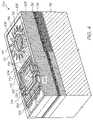
- FIG. 4shows a three dimensional view of the nozzle arrangement of FIG. 3 .
- reference numeral 30generally indicates a nozzle arrangement of a first embodiment of an ink jet printhead chip, in accordance with the invention, for an inkjet printhead.
- the nozzle arrangement 30is one of a plurality of such nozzle arrangements formed on a silicon wafer substrate 32 to define the printhead chip of the invention. As set out in the background of this specification, a single printhead can contain up to 84 000 such nozzle arrangements. For the purposes of clarity and ease of description, only one nozzle arrangement is described. It is to be appreciated that a person of ordinary skill in the field can readily obtain the printhead chip by simply replicating the nozzle arrangement 30 on the wafer substrate 32 .
- the printhead chipis the product of an integrated circuit fabrication technique.
- each nozzle arrangement 30is the product of a MEMS—based fabrication technique.
- a fabrication techniqueinvolves the deposition of functional layers and sacrificial layers of integrated circuit materials. The functional layers are etched to define various moving components and the sacrificial layers are etched away to release the components.
- fabrication techniquesgenerally involve the replication of a large number of similar components on a single wafer that is subsequently diced to separate the various components from each other. This reinforces the submission that a person of ordinary skill in the field can readily obtain the printhead chip of this invention by replicating the nozzle arrangement 30 .
- the electrical drive circuitry layer 34is positioned on the silicon wafer substrate 32 .
- the electrical drive circuitry layer 34includes CMOS drive circuitry.
- the particular configuration of the CMOS drive circuitryis not important to this description and has therefore been shown schematically in the drawings. Suffice to say that it is connected to a suitable microprocessor and provides electrical current to the nozzle arrangement 30 upon receipt of an enabling signal from said suitable microprocessor.
- An example of a suitable microprocessoris described in the above referenced patents/patent applications. It follows that this level of detail will not be set out in this specification.
- the ink passivation layer 36is positioned on the drive circuitry layer 34 .
- the ink passivation layer 36can be of any suitable material, such as silicon nitride.
- the nozzle arrangement 30includes a nozzle chamber structure 38 .
- the nozzle chamber structure 38defines a nozzle chamber 40 and has a roof 42 that defines an ink ejection port 44 .
- the nozzle chamber structure 38includes a pair of opposed sidewalls 46 , a distal end wall 48 and a proximal end wall 50 so that the nozzle chamber 40 is generally rectangular in plan.
- a plurality of ink inlet channels 52are defined through the silicon wafer substrate 32 , the drive circuitry layer 34 and the ink passivation layer 36 .
- One ink inlet channel 52is in fluid communication with each respective nozzle chamber 40 . Further, each ink inlet channel 52 is aligned with each respective ink ejection port 44 .
- the nozzle arrangement 30includes an ink-ejecting member in the form of a paddle 54 .
- the paddle 54is dimensioned to correspond generally with the nozzle chamber 40 . Further, the paddle 54 has a distal end portion 56 that is interposed between an opening 58 of the ink inlet channel 52 and the ink ejection port 44 .
- the paddle 54is angularly displaceable within the nozzle chamber 40 so that the distal end portion 56 can move towards and away from the ink ejection port 44 .
- the nozzle arrangement 30includes an actuator in the form of a thermal bend actuator 64 .
- This form of actuatoris also described in the above referenced applications and patents and is therefore not described in further detail in this specification.
- the thermal bend actuator 64includes an actuator arm 66 that has a fixed end 68 that is fixed to an anchor 70 and a working end 72 that is displaceable towards and away from the substrate 32 upon receipt of a drive signal in the form of a current pulse emanating from the drive circuitry layer 34 .
- the nozzle arrangement 30includes a sealing structure 78 that is interposed between the working end 72 of the actuator arm 66 and a proximal end portion 76 of the paddle 54 .
- the actuator arm 66 , the sealing structure 78 and the paddle 54are the product of a deposition and etching process carried out with a single material.
- the arm 66 , the sealing structure 78 and the paddle 54are discrete components. This facilitates fabrication of the nozzle arrangement 30 .
- the materialcan be any of a number of materials used in integrated circuit fabrication processes. However, it is a requirement that the material have a coefficient of thermal expansion that is such that the material is capable of expansion and contraction when heated and subsequently cooled to an extent sufficient to perform work on a MEMS scale. Further, it is preferable that the material be resiliently flexible.
- TiAlNtitanium aluminum nitride
- the nozzle arrangement 30includes a motion-transmitting structure 74 that interconnects the working end 72 of the actuator arm 66 and the proximal end portion 76 of the paddle 54 .
- the motion-transmitting structure 74bridges the sealing structure 78 so that the sealing structure 78 is interposed between at least a portion of the motion-transmitting structure 74 and the sealing structure 78 .
- the motion-transmitting structure 74includes an effort formation 80 that extends from the working end 72 of the actuator arm 66 .
- the motion-transmitting structure 74also includes a load formation 82 that extends from the proximal end portion 76 of the paddle 54 .
- a lever arm formation 84interconnects the effort and load formations 80 , 82 .
- the lever arm formation 84is pivotally connected between the sidewalls 46 with connectors in the form of opposed flexural connectors 85 .
- the flexural connectors 85are configured to experience torsional distortion upon pivotal movement of the lever arm formation 84 . It will therefore be appreciated that, upon reciprocal movement of the working end 72 of the actuator arm 66 , the lever arm formation 84 pivots. This pivotal movement results in the angular displacement of the paddle 54 , as described above, via the load formation 82 .
- the motion-transmitting structure 74 and the roof 42define a slotted opening 86 that accommodates relative movement of the structure 74 and the roof 42 .
- the slotted opening 86is interposed between a pair of ridges 88 that extend from the structure 74 and the roof 42 .
- the ridges 88are dimensioned so that, when the nozzle chamber 40 is filled with the ink 60 , a fluidic seal 90 is defined between the ridges 88 .
- the sealing structure 78 and the proximal end portion 76 of the paddle 54are configured so that a fluidic seal 92 is defined between the proximal end portion 76 and the sealing structure 78 .
- reference numeral 100generally indicates a nozzle arrangement of an inkjet printhead chip, in accordance with the invention, for an inkjet printhead.
- like reference numeralsrefer to like parts, unless otherwise specified.
- the nozzle arrangement 100includes nozzle chamber walls 102 positioned on the ink passivation layer 36 .
- a roof 104is positioned on the nozzle chamber walls 102 so that the roof 104 and the nozzle chamber walls 102 define a nozzle chamber 106 .
- the nozzle chamber walls 102include a distal end wall 108 , a proximal end wall 110 and a pair of opposed sidewalls 112 .
- An ink ejection port 114is defined in the roof 104 to be in fluid communication with the nozzle chamber 106 .
- the roof 104defines a nozzle rim 116 and a recess 118 positioned about the rim 116 to inhibit ink spread.
- the walls 102 and the roof 104are configured so that the nozzle chamber 106 is rectangular in plan.
- a plurality of ink inlet channels 120are defined through the substrate 32 , the drive circuitry layer 34 and the ink passivation layer 36 .
- the ink inlet channel 120is in fluid communication with the nozzle chamber 106 so that ink can be supplied to the nozzle chamber 106 .
- the nozzle arrangement 100includes a motion-transmitting structure 122 .
- the motion-transmitting structure 122includes an effort formation 124 , a lever arm formation 126 and a load formation 128 .
- the lever arm formation 126is interposed between the effort formation 124 and the load formation 128 .
- the nozzle arrangement 100includes a sealing structure 130 that is fast with the ink passivation layer 36 .
- the sealing structure 130is composite with a primary layer 132 and a secondary layer 134 .
- the layers 132 , 134are configured so that the sealing structure 130 is resiliently deformable to permit pivotal movement of the lever arm formation 126 with respect to the substrate 32 .
- the layers 132 , 134can be of a number of materials that are used in integrated circuit fabrication.
- TiAlNtitanium aluminum nitride
- TiAlNtitanium aluminum nitride
- the load formation 128defines part of the proximal end wall 110 .
- the load formation 128is composite with a primary layer 136 and a secondary layer 138 .
- the layers 136 , 138can be of any of a number of materials that are used in integrated circuit fabrication. However, as set out above, successive deposition and etching steps are used to fabricate the nozzle arrangement 100 . It follows that it is convenient for the layers 136 , 138 to be of the same material as the layers 132 , 134 . Thus, the layers 136 , 138 can be of TiAlN and titanium, respectively.
- the nozzle arrangement 100includes an ink-ejecting member in the form of an elongate rectangular paddle 140 .
- the paddle 140is fixed to the load formation 128 and extends towards the distal end wall 108 . Further, the paddle 140 is dimensioned to correspond generally with the nozzle chamber 106 . It follows that displacement of the paddle 140 towards and away from the ink ejection port 114 with sufficient energy results in the ejection of an ink drop from the ink ejection port. The manner in which drop ejection is achieved is described in detail in the above referenced patents/applications and is therefore not discussed in any detail here.
- the paddle 140is of TiAlN.
- the paddle 140is an extension of the layer 136 of the load formation 128 of the motion-transmitting structure 122 .
- the paddle 140has corrugations 142 to strengthen the paddle 140 against flexure during operation.
- the effort formation 124is also composite with a primary layer 144 and a secondary layer 146 .
- the layers 144 , 146can be of any of a number of materials that are used in integrated circuit fabrication. However, as set out above, successive deposition and etching steps are used to fabricate the nozzle arrangement 100 . It follows that it is convenient for the layers 144 , 146 to be of the same material as the layers 132 , 134 . Thus, the layers 144 , 146 can be of TiAlN and titanium, respectively.
- the nozzle arrangement 100includes an actuator in the form of a thermal bend actuator 148 .
- the thermal bend actuator 148is of a conductive material that is capable of being resistively heated.
- the conductive materialhas a coefficient of thermal expansion that is such that, when heated and subsequently cooled, the material is capable of expansion and contraction to an extent sufficient to perform work on a MEMS scale.
- the thermal bend actuator 148can be any of a number of thermal bend actuators described in the above patents/patent applications.
- the thermal bend actuator 148includes an actuator arm 150 that has an active portion 152 and a passive portion.
- the active portion 152has a pair of inner legs 154 and the passive portion is defined by a leg positioned on each side of the pair of inner legs 154 .
- a bridge portion 156interconnects the active inner legs 154 and the passive legs.
- Each leg 154is fixed to one of a pair of anchor formations in the form of active anchors 158 that extend from the ink passivation layer 36 .
- Each active anchor 158is configured so that the legs 154 are electrically connected to the drive circuitry layer 34 .
- Each passive legis fixed to one of a pair of anchor formations in the form of passive anchors 160 that are electrically isolated from the drive circuitry layer 34 .
- the legs 154 and the bridge portion 156are configured so that when a current from the drive circuitry layer 34 is set up in the legs 154 , the actuator arm 150 is subjected to differential heating.
- the actuator arm 150is shaped so that the passive legs are interposed between at least a portion of the legs 154 and the substrate 32 . It will be appreciated that this causes the actuator arm 150 to bend towards the substrate 32 .
- the bridge portion 156therefore defines a working end of the actuator 148 .
- the bridge portion 156defines the primary layer 144 of the effort formation 124 .
- the actuator 148is of TiAlN. The Applicant has found this material to be well suited for the actuator 148 .
- the lever arm formation 126is positioned on, and fast with, the secondary layers 134 , 138 , 146 of the sealing structure 130 , the load formation 128 and the effort formation 124 , respectively.
- reciprocal movement of the actuator 148 towards and away from the substrate 32is converted into reciprocal angular displacement of the paddle 140 via the motion-transmitting structure 122 to eject ink drops from the ink ejection port 114 .
- Each active anchor 158 and passive anchoris also composite with a primary layer 160 and a secondary layer 162 .
- the layers 160 , 162can be of any of a number of materials that are used in integrated circuit fabrication. However, in order to facilitate fabrication, the layer 160 is of TiAlN and the layer 162 is of titanium.
- a cover formation 164is positioned on the anchors to extend over and to cover the actuator 148 .
- Air chamber walls 166extend between the ink passivation layer 36 and the cover formation 164 so that the cover formation 164 and the air chamber walls 166 define an air chamber 168 .
- the actuator 148 and the anchorsare positioned in the air chamber 168 .
- the cover formation 164 , the lever arm formation 126 and the roof 104are in the form of a unitary protective structure 170 to inhibit damage to the nozzle arrangement 100 .
- the protective structure 170can be one of a number of materials that are used in integrated circuit fabrication. The Applicant has found that silicon dioxide is particularly useful for this task.
- lever arm formation 126it is necessary for the lever arm formation 126 to be displaced relative to the cover formation 164 and the roof 104 . It follows that the cover formation 164 and the lever arm formation 126 are demarcated by a slotted opening 172 in fluid communication with the air chamber 168 . The roof 104 and the lever arm formation 126 are demarcated by a slotted opening 174 in fluid communication with the nozzle chamber 106 .
- the lever arm formation 126 and the roof 104together define ridges 176 that bound the slotted opening 172 .
- the ridges 176define a fluidic seal during ink ejection.
- the ridges 176serve to inhibit ink spreading by providing suitable adhesion surfaces for a meniscus formed by the ink.
- the slotted openings 172 , 174demarcate resiliently flexible connectors in the form of a pair of opposed flexural connectors 178 defined by the protective structure 170 .
- the flexural connectors 178are configured to experience torsional deformation in order to accommodate pivotal movement of the lever arm formation 126 during operation of the nozzle arrangement 100 .
- the silicon dioxide of the protective structure 170is resiliently flexible on a MEMS scale and is thus suitable for such repetitive distortion.
- the paddle 140 , the sealing structure 130 and the actuator arm 150are discrete components. This facilitates fabrication of the nozzle arrangement 100 while still retaining the advantages of efficient motion transfer and sealing.
Landscapes
- Engineering & Computer Science (AREA)
- Manufacturing & Machinery (AREA)
- Physics & Mathematics (AREA)
- Theoretical Computer Science (AREA)
- General Physics & Mathematics (AREA)
- Computer Hardware Design (AREA)
- Computer Security & Cryptography (AREA)
- General Engineering & Computer Science (AREA)
- Chemical & Material Sciences (AREA)
- General Health & Medical Sciences (AREA)
- Multimedia (AREA)
- Electromagnetism (AREA)
- Signal Processing (AREA)
- Toxicology (AREA)
- Artificial Intelligence (AREA)
- Computer Vision & Pattern Recognition (AREA)
- Software Systems (AREA)
- Health & Medical Sciences (AREA)
- Nanotechnology (AREA)
- Materials Engineering (AREA)
- Crystallography & Structural Chemistry (AREA)
- Condensed Matter Physics & Semiconductors (AREA)
- Composite Materials (AREA)
- Microelectronics & Electronic Packaging (AREA)
- Human Computer Interaction (AREA)
- Particle Formation And Scattering Control In Inkjet Printers (AREA)
Abstract
Description
This is a Continuation Application of U.S. application Ser. No. 10/713,071, filed on Nov. 17, 2003, now issued U.S. Pat. No. 6,880,918, which is a Continuation Application of U.S. application Ser. No. 10/302,275, filed on Nov. 23, 2002, now issued U.S. Pat. No. 6,669,332, which is a Continuation Application of U.S. application Ser. No. 10/120,347, filed on Apr. 12, 2002, now issued U.S. Pat. No. 6,540,332, which is a Continuation-in-Part of U.S. application Ser. No. 09/112,767, filed on Jul. 10, 1998, now issued U.S. Pat. No. 6,416,167. Application Ser. No's. 10/713,071, 10/120,347 and 09/112,767 are entirely herein incorporated by reference.
This invention relates to a micro-electromechanical device. More particularly, this invention relates to a micro-electromechanical device that incorporates a motion-transmitting structure.
The following patents/patent applications are incorporated by reference. U.S. Pat. Nos. 6,227,652 6,213,588 6,213,589 6,231,163 6,247,795 6,394,581 6,244,691 6,257,704 6,416,168 6,220,694 6,257,705 6,247,794 6,234,610 6,247,793 6,264,306 6,241,342 6,247,792 6,264,307 6,254,220 6,234,611 6,302,528 6,283,582 6,239,821 6,338,547 6,247,796 6,557,977 6,390,603 6,362,843 6,293,653 6,312,107 6,227,653 6,234,609 6,238,040 6,188,415 6,227,654 6,209,989 6,247,791 6,336710 6,217,153 6,416,167 6,243,113 6,283,581 6,247,790 6,260,953 6,267,469 6,273,544 6,309,048 6,420,196 6,443,558 6,439,689 6,378,989 6,848,181 6,634,735 6,623,101 6,406,129 6,505,916 6,457,809 6,550,895 6,457,812 6,428,133 6,362,868 6,485,123 6,425,657 6,488,358 Ser. No. 09/854,830 U.S. Pat. Nos. 6,712,986 6,981,757 6,505,912 6,439,694 6,364,461 6,378,990 6,425,658 6,488,361 6,814,429 6,471,336 6,457,813 6,540,331 6,454,396 6,464,325 6,443,559 6,435,664 6,447,100 Ser. No. 09/900,160 U.S. Pat. Nos. 6,439,695 6,488,360 6,488,359 6,550,896 6,618,117 6,803,989 Ser. No. 09/922,158 U.S. Pat. Nos. 6,416,154 6,547,364 6,644,771 6,565,181 6,857,719 6,702,417 6,918,654 6,616,271 6,623,108 6,625,874 6,547,368 6,508,546
As set out in the above referenced applications/patents, the Applicant has spent a substantial amount of time and effort in developing printheads that incorporate micro electro-mechanical system (MEMS)—based components to achieve the ejection of ink necessary for printing.
As a result of the Applicant's research and development, the Applicant has been able to develop printheads having one or more printhead chips that together incorporate up to 84 000 nozzle arrangements. The Applicant has also developed suitable processor technology that is capable of controlling operation of such printheads. In particular, the processor technology and the printheads are capable of cooperating to generate resolutions of 1600 dpi and higher in some cases. Examples of suitable processor technology are provided in the above referenced patent applications/patents.
Common to most of the printhead chips that the Applicant has developed is a component that moves with respect to a substrate to eject ink from a nozzle chamber. This component can be in the form of an ink-ejecting member that is displaceable in a nozzle chamber to eject the ink from the nozzle chamber.
A particular difficulty that the Applicant has been faced with is to achieve a suitable interface between a prime mover in the form of an actuator and the moving component. This interface is required to permit the moving component to be displaced in the nozzle chamber and to inhibit leakage of ink from the nozzle chamber.
As set out in the above referenced patents/patent applications, the printhead chip is manufactured using integrated circuit fabrication techniques. This is the usual manner in which MEMS-based devices are fabricated. Such forms of fabrication are subject to constraints since they involve successive deposition and etching techniques. It follows that MEMS-based devices are usually formed in layers and that components having relatively complex shapes are difficult and expensive to fabricate.
InFIG. 1 ,reference numeral 10 generally indicates part of a nozzle arrangement of a printhead chip. Thepart 10 shown illustrates anactuator 12 and an ink-ejectingmember 14. Theactuator 12 includes anelongate actuator arm 16 that extends from ananchor 18. Theactuator arm 16 is configured so that, when it receives a drive signal, theactuator arm 16 bends towards asubstrate 20 as indicated by anarrow 22. Aconnecting formation 24 is interposed between theactuator arm 16 and the ink-ejectingmember 14. Thus, when theactuator arm 16 is bent towards thesubstrate 20, the ink-ejectingmember 14 is displaced in the direction of anarrow 26 to eject ink from the nozzle chamber.
It would be intuitive simply to use thearrangement 10 together with a suitable sealing structure to achieve effective ink ejection and sealing. The reason for this is that it would appear that theactuator arm 16, the connectingformation 24 and the ink-ejectingmember 14 could be in the form of a unitary structure. However, the Applicant has found that it is not possible to achieve a working configuration as shown by using MEMS-based fabrication techniques. In particular, it has been found by the Applicant that such a unitary structure does not lend itself to such fabrication techniques.
It follows that the Applicant has been led to conceive the present invention.
According to a first aspect of the invention, there is provided a micro-electromechanical device that comprises
a substrate that incorporates drive circuitry;
an elongate drive member, the drive member being fast with the substrate at a fixed end and incorporating an electrical circuit that is in electrical contact with the drive circuitry to receive an electrical signal from the drive circuitry, the drive member being configured so that a free end is displaced relative to the substrate on receipt of the electrical signal;
a motion-transmitting member that is fast with the free end of the drive member so that the motion-transmitting member is displaced together with the free end; and
a working member that is fast with the motion-transmitting member to be displaced together with the motion-transmitting member to perform work.
The motion-transmitting member may define a first class lever and may have an effort formation that is fast with the free end of the drive member, a load formation that is fast with the working member and a fulcrum formation that is fast with the substrate. The effort and load formations may be pivotal with respect to the fulcrum formation.
The drive member may be a thermal bend actuator of the type that uses differential thermal expansion to achieve displacement.
The thermal bend actuator may be of a conductive material that is capable of thermal expansion and may have an active portion and a passive portion. The active portion may define the electrical circuit, in the form of a heating circuit, so that the active portion is heated and expands relative to the passive portion on receipt of the electrical signal to generate displacement of the actuator in one direction and termination of the signal results in cooling contraction of the active portion to generate displacement of the actuator in an opposite direction.
The conductive material of the actuator may be resiliently flexible to facilitate said displacement of the actuator in the opposite direction.
The drive member and the working member may be of the same material, while the motion-transmitting member may be of a different material to that of the drive member and the working member.
The drive member and the working member may both be of titanium nitride.
According to a second aspect of the invention, there is provided a micro-electromechanical device that comprises
a substrate that incorporates drive circuitry;
a plurality of elongate drive members, each drive member being fast with the substrate at a fixed end and incorporating an electrical circuit that is in electrical contact with the drive circuitry to receive an electrical signal from the drive circuitry, the drive member being configured so that a free end is displaced relative to the substrate on receipt of the electrical signal;
a plurality of motion-transmitting members fast with respective free ends of the drive members so that each motion-transmitting member is displaced together with its associated free end; and
a plurality of working members fast with respective motion-transmitting members so that each working member is displaced together with its associated motion-transmitting member to perform work.
According to a third aspect of the invention, there is provided a printhead chip for an inkjet printhead, the printhead chip comprising
a substrate; and
a plurality of nozzle arrangements positioned on the substrate, each nozzle arrangement comprising
- a nozzle chamber structure that defines a nozzle chamber in which ink is received;
- an ink-ejecting member that is positioned in the nozzle chamber and is displaceable in the nozzle chamber to eject ink from the nozzle chamber;
at least one actuator that is positioned on the substrate, the, or each, actuator having a working portion that is displaceable with respect to the substrate when the actuator receives a driving signal;
a sealing structure that is positioned on the substrate and is interposed between the, or each, actuator and the ink-ejecting member to inhibit a passage of ink between the ink-ejecting member and the actuator; and
a motion-transmitting structure that bridges the sealing structure, the motion-transmitting structure interconnecting the working portion of the actuator and the ink-ejecting member so that displacement of the working portion relative to the substrate is transmitted to the ink-ejecting member.
The invention is now described, by way of example, with reference to the accompanying drawings. The following description is not intended to limit the broad scope of the above summary.
In the drawings,
InFIG. 2 ,reference numeral 30 generally indicates a nozzle arrangement of a first embodiment of an ink jet printhead chip, in accordance with the invention, for an inkjet printhead.
Thenozzle arrangement 30 is one of a plurality of such nozzle arrangements formed on asilicon wafer substrate 32 to define the printhead chip of the invention. As set out in the background of this specification, a single printhead can contain up to 84 000 such nozzle arrangements. For the purposes of clarity and ease of description, only one nozzle arrangement is described. It is to be appreciated that a person of ordinary skill in the field can readily obtain the printhead chip by simply replicating thenozzle arrangement 30 on thewafer substrate 32.
The printhead chip is the product of an integrated circuit fabrication technique. In particular, eachnozzle arrangement 30 is the product of a MEMS—based fabrication technique. As is known, such a fabrication technique involves the deposition of functional layers and sacrificial layers of integrated circuit materials. The functional layers are etched to define various moving components and the sacrificial layers are etched away to release the components. As is known, such fabrication techniques generally involve the replication of a large number of similar components on a single wafer that is subsequently diced to separate the various components from each other. This reinforces the submission that a person of ordinary skill in the field can readily obtain the printhead chip of this invention by replicating thenozzle arrangement 30.
An electricaldrive circuitry layer 34 is positioned on thesilicon wafer substrate 32. The electricaldrive circuitry layer 34 includes CMOS drive circuitry. The particular configuration of the CMOS drive circuitry is not important to this description and has therefore been shown schematically in the drawings. Suffice to say that it is connected to a suitable microprocessor and provides electrical current to thenozzle arrangement 30 upon receipt of an enabling signal from said suitable microprocessor. An example of a suitable microprocessor is described in the above referenced patents/patent applications. It follows that this level of detail will not be set out in this specification.
Anink passivation layer 36 is positioned on thedrive circuitry layer 34. Theink passivation layer 36 can be of any suitable material, such as silicon nitride.
Thenozzle arrangement 30 includes anozzle chamber structure 38. Thenozzle chamber structure 38 defines anozzle chamber 40 and has aroof 42 that defines anink ejection port 44.
Thenozzle chamber structure 38 includes a pair ofopposed sidewalls 46, adistal end wall 48 and a proximal end wall50 so that thenozzle chamber 40 is generally rectangular in plan.
A plurality ofink inlet channels 52 are defined through thesilicon wafer substrate 32, thedrive circuitry layer 34 and theink passivation layer 36. Oneink inlet channel 52 is in fluid communication with eachrespective nozzle chamber 40. Further, eachink inlet channel 52 is aligned with each respectiveink ejection port 44.
Thenozzle arrangement 30 includes an ink-ejecting member in the form of apaddle 54. Thepaddle 54 is dimensioned to correspond generally with thenozzle chamber 40. Further, thepaddle 54 has adistal end portion 56 that is interposed between an opening58 of theink inlet channel 52 and theink ejection port 44. Thepaddle 54 is angularly displaceable within thenozzle chamber 40 so that thedistal end portion 56 can move towards and away from theink ejection port 44. Thus, when thenozzle chamber 40 is filled withink 60, such movement of thepaddle 54 results in a fluctuation of ink pressure within thenozzle chamber 40 so that anink drop 62 is ejected from theink ejection port 44. The mechanism of ink drop ejection is fully set out in the above referenced applications and patents. It follows that this detail is not set out in this specification.
Thenozzle arrangement 30 includes an actuator in the form of athermal bend actuator 64. This form of actuator is also described in the above referenced applications and patents and is therefore not described in further detail in this specification. Briefly, however, thethermal bend actuator 64 includes anactuator arm 66 that has a fixedend 68 that is fixed to ananchor 70 and a workingend 72 that is displaceable towards and away from thesubstrate 32 upon receipt of a drive signal in the form of a current pulse emanating from thedrive circuitry layer 34.
Thenozzle arrangement 30 includes a sealing structure78 that is interposed between the workingend 72 of theactuator arm 66 and aproximal end portion 76 of thepaddle 54. Theactuator arm 66, the sealing structure78 and thepaddle 54 are the product of a deposition and etching process carried out with a single material. However, thearm 66, the sealing structure78 and thepaddle 54 are discrete components. This facilitates fabrication of thenozzle arrangement 30.
The material can be any of a number of materials used in integrated circuit fabrication processes. However, it is a requirement that the material have a coefficient of thermal expansion that is such that the material is capable of expansion and contraction when heated and subsequently cooled to an extent sufficient to perform work on a MEMS scale. Further, it is preferable that the material be resiliently flexible. The Applicant has found that titanium aluminum nitride (TiAlN) is particularly suited for the task.
Thenozzle arrangement 30 includes a motion-transmitting structure74 that interconnects the workingend 72 of theactuator arm 66 and theproximal end portion 76 of thepaddle 54. The motion-transmitting structure74 bridges the sealing structure78 so that the sealing structure78 is interposed between at least a portion of the motion-transmitting structure74 and the sealing structure78.
The motion-transmitting structure74 includes aneffort formation 80 that extends from the workingend 72 of theactuator arm 66. The motion-transmitting structure74 also includes a load formation82 that extends from theproximal end portion 76 of thepaddle 54. Alever arm formation 84 interconnects the effort andload formations 80,82. Thelever arm formation 84 is pivotally connected between the sidewalls46 with connectors in the form of opposedflexural connectors 85. Theflexural connectors 85 are configured to experience torsional distortion upon pivotal movement of thelever arm formation 84. It will therefore be appreciated that, upon reciprocal movement of the workingend 72 of theactuator arm 66, thelever arm formation 84 pivots. This pivotal movement results in the angular displacement of thepaddle 54, as described above, via the load formation82.
The motion-transmitting structure74 and theroof 42 define a slottedopening 86 that accommodates relative movement of the structure74 and theroof 42. The slottedopening 86 is interposed between a pair ofridges 88 that extend from the structure74 and theroof 42. Theridges 88 are dimensioned so that, when thenozzle chamber 40 is filled with theink 60, afluidic seal 90 is defined between theridges 88. Similarly, the sealing structure78 and theproximal end portion 76 of thepaddle 54 are configured so that a fluidic seal92 is defined between theproximal end portion 76 and the sealing structure78.
InFIGS. 3 and 4 ,reference numeral 100 generally indicates a nozzle arrangement of an inkjet printhead chip, in accordance with the invention, for an inkjet printhead. With reference toFIG. 2 , like reference numerals refer to like parts, unless otherwise specified.
Thenozzle arrangement 100 includesnozzle chamber walls 102 positioned on theink passivation layer 36. Aroof 104 is positioned on thenozzle chamber walls 102 so that theroof 104 and thenozzle chamber walls 102 define anozzle chamber 106. Thenozzle chamber walls 102 include adistal end wall 108, aproximal end wall 110 and a pair ofopposed sidewalls 112. Anink ejection port 114 is defined in theroof 104 to be in fluid communication with thenozzle chamber 106. Theroof 104 defines anozzle rim 116 and arecess 118 positioned about therim 116 to inhibit ink spread. Thewalls 102 and theroof 104 are configured so that thenozzle chamber 106 is rectangular in plan.
A plurality ofink inlet channels 120, one of which is shown in the drawings, are defined through thesubstrate 32, thedrive circuitry layer 34 and theink passivation layer 36. Theink inlet channel 120 is in fluid communication with thenozzle chamber 106 so that ink can be supplied to thenozzle chamber 106.
Thenozzle arrangement 100 includes a motion-transmittingstructure 122. The motion-transmittingstructure 122 includes an effort formation124, alever arm formation 126 and aload formation 128. Thelever arm formation 126 is interposed between the effort formation124 and theload formation 128.
Thenozzle arrangement 100 includes a sealingstructure 130 that is fast with theink passivation layer 36. In particular, the sealingstructure 130 is composite with aprimary layer 132 and asecondary layer 134. Thelayers structure 130 is resiliently deformable to permit pivotal movement of thelever arm formation 126 with respect to thesubstrate 32. Thelayers layer 132 and that titanium is a suitable material for thelayer 134.
Theload formation 128 defines part of theproximal end wall 110. Theload formation 128 is composite with a primary layer136 and asecondary layer 138. As with the sealingstructure 130, thelayers 136,138 can be of any of a number of materials that are used in integrated circuit fabrication. However, as set out above, successive deposition and etching steps are used to fabricate thenozzle arrangement 100. It follows that it is convenient for thelayers 136,138 to be of the same material as thelayers layers 136,138 can be of TiAlN and titanium, respectively.
Thenozzle arrangement 100 includes an ink-ejecting member in the form of an elongaterectangular paddle 140. Thepaddle 140 is fixed to theload formation 128 and extends towards thedistal end wall 108. Further, thepaddle 140 is dimensioned to correspond generally with thenozzle chamber 106. It follows that displacement of thepaddle 140 towards and away from theink ejection port 114 with sufficient energy results in the ejection of an ink drop from the ink ejection port. The manner in which drop ejection is achieved is described in detail in the above referenced patents/applications and is therefore not discussed in any detail here.
To facilitate fabrication, thepaddle 140 is of TiAlN. In particular, thepaddle 140 is an extension of the layer136 of theload formation 128 of the motion-transmittingstructure 122.
Thepaddle 140 hascorrugations 142 to strengthen thepaddle 140 against flexure during operation.
The effort formation124 is also composite with aprimary layer 144 and asecondary layer 146.
Thelayers nozzle arrangement 100. It follows that it is convenient for thelayers layers layers
Thenozzle arrangement 100 includes an actuator in the form of athermal bend actuator 148. Thethermal bend actuator 148 is of a conductive material that is capable of being resistively heated. The conductive material has a coefficient of thermal expansion that is such that, when heated and subsequently cooled, the material is capable of expansion and contraction to an extent sufficient to perform work on a MEMS scale.
Thethermal bend actuator 148 can be any of a number of thermal bend actuators described in the above patents/patent applications. In one example, thethermal bend actuator 148 includes anactuator arm 150 that has anactive portion 152 and a passive portion. Theactive portion 152 has a pair ofinner legs 154 and the passive portion is defined by a leg positioned on each side of the pair ofinner legs 154. Abridge portion 156 interconnects the activeinner legs 154 and the passive legs. Eachleg 154 is fixed to one of a pair of anchor formations in the form ofactive anchors 158 that extend from theink passivation layer 36. Eachactive anchor 158 is configured so that thelegs 154 are electrically connected to thedrive circuitry layer 34.
Each passive leg is fixed to one of a pair of anchor formations in the form of passive anchors160 that are electrically isolated from thedrive circuitry layer 34.
Thus, thelegs 154 and thebridge portion 156 are configured so that when a current from thedrive circuitry layer 34 is set up in thelegs 154, theactuator arm 150 is subjected to differential heating. In particular, theactuator arm 150 is shaped so that the passive legs are interposed between at least a portion of thelegs 154 and thesubstrate 32. It will be appreciated that this causes theactuator arm 150 to bend towards thesubstrate 32.
Thebridge portion 156 therefore defines a working end of theactuator 148. In particular, thebridge portion 156 defines theprimary layer 144 of the effort formation124. Thus, theactuator 148 is of TiAlN. The Applicant has found this material to be well suited for theactuator 148.
Thelever arm formation 126 is positioned on, and fast with, thesecondary layers structure 130, theload formation 128 and the effort formation124, respectively. Thus, reciprocal movement of theactuator 148 towards and away from thesubstrate 32 is converted into reciprocal angular displacement of thepaddle 140 via the motion-transmittingstructure 122 to eject ink drops from theink ejection port 114.
Eachactive anchor 158 and passive anchor is also composite with a primary layer160 and a secondary layer162. The layers160,162 can be of any of a number of materials that are used in integrated circuit fabrication. However, in order to facilitate fabrication, the layer160 is of TiAlN and the layer162 is of titanium.
Acover formation 164 is positioned on the anchors to extend over and to cover theactuator 148.Air chamber walls 166 extend between theink passivation layer 36 and thecover formation 164 so that thecover formation 164 and theair chamber walls 166 define anair chamber 168. Thus, theactuator 148 and the anchors are positioned in theair chamber 168.
Thecover formation 164, thelever arm formation 126 and theroof 104 are in the form of a unitaryprotective structure 170 to inhibit damage to thenozzle arrangement 100.
Theprotective structure 170 can be one of a number of materials that are used in integrated circuit fabrication. The Applicant has found that silicon dioxide is particularly useful for this task.
It will be appreciated that it is necessary for thelever arm formation 126 to be displaced relative to thecover formation 164 and theroof 104. It follows that thecover formation 164 and thelever arm formation 126 are demarcated by a slottedopening 172 in fluid communication with theair chamber 168. Theroof 104 and thelever arm formation 126 are demarcated by a slottedopening 174 in fluid communication with thenozzle chamber 106.
Thelever arm formation 126 and theroof 104 together defineridges 176 that bound the slottedopening 172. Thus, when thenozzle chamber 106 is filled with ink, theridges 176 define a fluidic seal during ink ejection. Theridges 176 serve to inhibit ink spreading by providing suitable adhesion surfaces for a meniscus formed by the ink.
The slottedopenings flexural connectors 178 defined by theprotective structure 170. Theflexural connectors 178 are configured to experience torsional deformation in order to accommodate pivotal movement of thelever arm formation 126 during operation of thenozzle arrangement 100. The silicon dioxide of theprotective structure 170 is resiliently flexible on a MEMS scale and is thus suitable for such repetitive distortion.
It should be noted that thepaddle 140, the sealingstructure 130 and theactuator arm 150 are discrete components. This facilitates fabrication of thenozzle arrangement 100 while still retaining the advantages of efficient motion transfer and sealing.
Claims (9)
1. A printer having a microelectromechanical printhead including:
a substrate with a layer containing electronic drive circuitry;
a plurality of electrically actuated ink ejection assemblies formed into the substrate and responsive to the electronic drive circuitry, the ink ejection assemblies including:
an actuator responsive to an electrical signal from the electronic drive circuitry; and
an ink ejection member responsive to the actuator at a first end and disposed to interact with an ink chamber of the ink ejection assembly at a second end in order to eject ink upon operation of the actuator.
2. A printer according toclaim 1 including a motion transmitting structure arranged to transmit force from the actuator to the ink ejection member.
3. A printer according toclaim 2 , wherein the actuator includes an elongate actuator arm attached to the substrate and a displaceable end distal to the attachment and coupled to the motion transmitting structure.
4. A printer according toclaim 3 , wherein the actuator comprises a thermal bend actuator arranged to apply force to the motion transmitting structure in response to the electrical signal from the electronic drive circuitry.
5. A printer according toclaim 1 including a seal arranged to inhibit passage of ink between the ink ejection member and the actuator in use.
6. A printer according toclaim 1 formed by an integrated circuit fabrication process.
7. A printer according toclaim 1 , in which the ink chamber is formed with a roof that defines an ink outlet port.
8. A printer according toclaim 7 , including a nozzle rim formed around the outside perimeter of the ink outlet port.
9. A printer according toclaim 8 , including a number of recesses formed about the nozzle rim to inhibit ink spread.
Priority Applications (5)
| Application Number | Priority Date | Filing Date | Title |
|---|---|---|---|
| US11/013,462US7083261B2 (en) | 1997-07-15 | 2004-12-17 | Printer incorporating a microelectromechanical printhead |
| US11/442,190US7258425B2 (en) | 1997-07-15 | 2006-05-30 | Printhead incorporating leveraged micro-electromechanical actuation |
| US11/779,272US7401902B2 (en) | 1997-07-15 | 2007-07-17 | Inkjet nozzle arrangement incorporating a thermal bend actuator with an ink ejection paddle |
| US12/140,129US7549732B2 (en) | 1997-07-15 | 2008-06-16 | Printhead having nozzle arrangements with sealing structures |
| US12/475,572US7938509B2 (en) | 1997-07-15 | 2009-05-31 | Nozzle arrangement with sealing structure |
Applications Claiming Priority (9)
| Application Number | Priority Date | Filing Date | Title |
|---|---|---|---|
| AUPO7991AAUPO799197A0 (en) | 1997-07-15 | 1997-07-15 | Image processing method and apparatus (ART01) |
| AUPO7991 | 1997-07-15 | ||
| AUPO259298 | 1998-03-25 | ||
| AUPO2592 | 1998-03-25 | ||
| US09/112,767US6416167B1 (en) | 1997-07-15 | 1998-07-10 | Thermally actuated ink jet printing mechanism having a series of thermal actuator units |
| US10/120,347US6540332B2 (en) | 1997-07-15 | 2002-04-12 | Motion transmitting structure for a nozzle arrangement of a printhead chip for an inkjet printhead |
| US10/302,275US6669332B2 (en) | 1997-07-15 | 2002-11-23 | Printhead chip having a plurality of nozzle arrangements that each incorporate a motion transmitting structure |
| US10/713,071US6880918B2 (en) | 1997-07-15 | 2003-11-17 | Micro-electromechanical device that incorporates a motion-transmitting structure |
| US11/013,462US7083261B2 (en) | 1997-07-15 | 2004-12-17 | Printer incorporating a microelectromechanical printhead |
Related Parent Applications (1)
| Application Number | Title | Priority Date | Filing Date |
|---|---|---|---|
| US10/713,071ContinuationUS6880918B2 (en) | 1997-07-15 | 2003-11-17 | Micro-electromechanical device that incorporates a motion-transmitting structure |
Related Child Applications (1)
| Application Number | Title | Priority Date | Filing Date |
|---|---|---|---|
| US11/442,190ContinuationUS7258425B2 (en) | 1997-07-15 | 2006-05-30 | Printhead incorporating leveraged micro-electromechanical actuation |
Publications (2)
| Publication Number | Publication Date |
|---|---|
| US20050093937A1 US20050093937A1 (en) | 2005-05-05 |
| US7083261B2true US7083261B2 (en) | 2006-08-01 |
Family
ID=46303486
Family Applications (18)
| Application Number | Title | Priority Date | Filing Date |
|---|---|---|---|
| US11/008,115Expired - Fee RelatedUS7337532B2 (en) | 1997-07-15 | 2004-12-10 | Method of manufacturing micro-electromechanical device having motion-transmitting structure |
| US11/013,462Expired - Fee RelatedUS7083261B2 (en) | 1997-07-15 | 2004-12-17 | Printer incorporating a microelectromechanical printhead |
| US11/038,201Expired - Fee RelatedUS6976751B2 (en) | 1997-07-15 | 2005-01-21 | Motion transmitting structure |
| US11/165,183Expired - Fee RelatedUS7055934B2 (en) | 1997-07-15 | 2005-06-24 | Inkjet nozzle comprising a motion-transmitting structure |
| US11/442,190Expired - Fee RelatedUS7258425B2 (en) | 1997-07-15 | 2006-05-30 | Printhead incorporating leveraged micro-electromechanical actuation |
| US11/442,191Expired - Fee RelatedUS7252367B2 (en) | 1997-07-15 | 2006-05-30 | Inkjet printhead having paddled inkjet nozzles |
| US11/513,073Expired - Fee RelatedUS7517057B2 (en) | 1997-07-15 | 2006-08-31 | Nozzle arrangement for an inkjet printhead that incorporates a movement transfer mechanism |
| US11/764,746Expired - Fee RelatedUS7322679B2 (en) | 1997-07-15 | 2007-06-18 | Inkjet nozzle arrangement with thermal bend actuator capable of differential thermal expansion |
| US11/779,272Expired - Fee RelatedUS7401902B2 (en) | 1997-07-15 | 2007-07-17 | Inkjet nozzle arrangement incorporating a thermal bend actuator with an ink ejection paddle |
| US11/954,988Expired - Fee RelatedUS7465027B2 (en) | 1997-07-15 | 2007-12-12 | Nozzle arrangement for a printhead integrated circuit incorporating a lever mechanism |
| US12/015,261Expired - Fee RelatedUS7641314B2 (en) | 1997-07-15 | 2008-01-16 | Printhead micro-electromechanical nozzle arrangement with a motion-transmitting structure |
| US12/140,129Expired - Fee RelatedUS7549732B2 (en) | 1997-07-15 | 2008-06-16 | Printhead having nozzle arrangements with sealing structures |
| US12/276,365Expired - Fee RelatedUS7611227B2 (en) | 1997-07-15 | 2008-11-23 | Nozzle arrangement for a printhead integrated circuit |
| US12/422,949Expired - Fee RelatedUS7914122B2 (en) | 1997-07-15 | 2009-04-13 | Inkjet printhead nozzle arrangement with movement transfer mechanism |
| US12/475,572Expired - Fee RelatedUS7938509B2 (en) | 1997-07-15 | 2009-05-31 | Nozzle arrangement with sealing structure |
| US12/605,369Expired - Fee RelatedUS7967416B2 (en) | 1997-07-15 | 2009-10-25 | Sealed nozzle arrangement for printhead |
| US12/627,997Expired - Fee RelatedUS7976130B2 (en) | 1997-07-15 | 2009-11-30 | Printhead micro-electromechanical nozzle arrangement with motion-transmitting structure |
| US13/103,090Expired - Fee RelatedUS8123336B2 (en) | 1997-07-15 | 2011-05-08 | Printhead micro-electromechanical nozzle arrangement with motion-transmitting structure |
Family Applications Before (1)
| Application Number | Title | Priority Date | Filing Date |
|---|---|---|---|
| US11/008,115Expired - Fee RelatedUS7337532B2 (en) | 1997-07-15 | 2004-12-10 | Method of manufacturing micro-electromechanical device having motion-transmitting structure |
Family Applications After (16)
| Application Number | Title | Priority Date | Filing Date |
|---|---|---|---|
| US11/038,201Expired - Fee RelatedUS6976751B2 (en) | 1997-07-15 | 2005-01-21 | Motion transmitting structure |
| US11/165,183Expired - Fee RelatedUS7055934B2 (en) | 1997-07-15 | 2005-06-24 | Inkjet nozzle comprising a motion-transmitting structure |
| US11/442,190Expired - Fee RelatedUS7258425B2 (en) | 1997-07-15 | 2006-05-30 | Printhead incorporating leveraged micro-electromechanical actuation |
| US11/442,191Expired - Fee RelatedUS7252367B2 (en) | 1997-07-15 | 2006-05-30 | Inkjet printhead having paddled inkjet nozzles |
| US11/513,073Expired - Fee RelatedUS7517057B2 (en) | 1997-07-15 | 2006-08-31 | Nozzle arrangement for an inkjet printhead that incorporates a movement transfer mechanism |
| US11/764,746Expired - Fee RelatedUS7322679B2 (en) | 1997-07-15 | 2007-06-18 | Inkjet nozzle arrangement with thermal bend actuator capable of differential thermal expansion |
| US11/779,272Expired - Fee RelatedUS7401902B2 (en) | 1997-07-15 | 2007-07-17 | Inkjet nozzle arrangement incorporating a thermal bend actuator with an ink ejection paddle |
| US11/954,988Expired - Fee RelatedUS7465027B2 (en) | 1997-07-15 | 2007-12-12 | Nozzle arrangement for a printhead integrated circuit incorporating a lever mechanism |
| US12/015,261Expired - Fee RelatedUS7641314B2 (en) | 1997-07-15 | 2008-01-16 | Printhead micro-electromechanical nozzle arrangement with a motion-transmitting structure |
| US12/140,129Expired - Fee RelatedUS7549732B2 (en) | 1997-07-15 | 2008-06-16 | Printhead having nozzle arrangements with sealing structures |
| US12/276,365Expired - Fee RelatedUS7611227B2 (en) | 1997-07-15 | 2008-11-23 | Nozzle arrangement for a printhead integrated circuit |
| US12/422,949Expired - Fee RelatedUS7914122B2 (en) | 1997-07-15 | 2009-04-13 | Inkjet printhead nozzle arrangement with movement transfer mechanism |
| US12/475,572Expired - Fee RelatedUS7938509B2 (en) | 1997-07-15 | 2009-05-31 | Nozzle arrangement with sealing structure |
| US12/605,369Expired - Fee RelatedUS7967416B2 (en) | 1997-07-15 | 2009-10-25 | Sealed nozzle arrangement for printhead |
| US12/627,997Expired - Fee RelatedUS7976130B2 (en) | 1997-07-15 | 2009-11-30 | Printhead micro-electromechanical nozzle arrangement with motion-transmitting structure |
| US13/103,090Expired - Fee RelatedUS8123336B2 (en) | 1997-07-15 | 2011-05-08 | Printhead micro-electromechanical nozzle arrangement with motion-transmitting structure |
Country Status (1)
| Country | Link |
|---|---|
| US (18) | US7337532B2 (en) |
Cited By (1)
| Publication number | Priority date | Publication date | Assignee | Title |
|---|---|---|---|---|
| US8523916B2 (en) | 2003-12-16 | 2013-09-03 | DePuy Synthes Products, LLC | Methods and devices for spinal fixation element placement |
Families Citing this family (40)
| Publication number | Priority date | Publication date | Assignee | Title |
|---|---|---|---|---|
| US7556356B1 (en) | 1997-07-15 | 2009-07-07 | Silverbrook Research Pty Ltd | Inkjet printhead integrated circuit with ink spread prevention |
| US6188415B1 (en) | 1997-07-15 | 2001-02-13 | Silverbrook Research Pty Ltd | Ink jet printer having a thermal actuator comprising an external coil spring |
| US6712453B2 (en) | 1997-07-15 | 2004-03-30 | Silverbrook Research Pty Ltd. | Ink jet nozzle rim |
| US6582059B2 (en)* | 1997-07-15 | 2003-06-24 | Silverbrook Research Pty Ltd | Discrete air and nozzle chambers in a printhead chip for an inkjet printhead |
| US7011390B2 (en)* | 1997-07-15 | 2006-03-14 | Silverbrook Research Pty Ltd | Printing mechanism having wide format printing zone |
| US6935724B2 (en) | 1997-07-15 | 2005-08-30 | Silverbrook Research Pty Ltd | Ink jet nozzle having actuator with anchor positioned between nozzle chamber and actuator connection point |
| US6485123B2 (en)* | 1997-07-15 | 2002-11-26 | Silverbrook Research Pty Ltd | Shutter ink jet |
| US6471336B2 (en)* | 1997-07-15 | 2002-10-29 | Silverbrook Research Pty Ltd. | Nozzle arrangement that incorporates a reversible actuating mechanism |
| US7287836B2 (en)* | 1997-07-15 | 2007-10-30 | Sil;Verbrook Research Pty Ltd | Ink jet printhead with circular cross section chamber |
| US20110228008A1 (en)* | 1997-07-15 | 2011-09-22 | Silverbrook Research Pty Ltd | Printhead having relatively sized fluid ducts and nozzles |
| US20100277531A1 (en)* | 1997-07-15 | 2010-11-04 | Silverbrook Research Pty Ltd | Printer having processor for high volume printing |
| US6648453B2 (en)* | 1997-07-15 | 2003-11-18 | Silverbrook Research Pty Ltd | Ink jet printhead chip with predetermined micro-electromechanical systems height |
| US7337532B2 (en)* | 1997-07-15 | 2008-03-04 | Silverbrook Research Pty Ltd | Method of manufacturing micro-electromechanical device having motion-transmitting structure |
| US6682174B2 (en) | 1998-03-25 | 2004-01-27 | Silverbrook Research Pty Ltd | Ink jet nozzle arrangement configuration |
| US6513908B2 (en)* | 1997-07-15 | 2003-02-04 | Silverbrook Research Pty Ltd | Pusher actuation in a printhead chip for an inkjet printhead |
| AUPP653998A0 (en)* | 1998-10-16 | 1998-11-05 | Silverbrook Research Pty Ltd | Micromechanical device and method (ij46B) |
| US20040130599A1 (en)* | 1997-07-15 | 2004-07-08 | Silverbrook Research Pty Ltd | Ink jet printhead with amorphous ceramic chamber |
| US7468139B2 (en) | 1997-07-15 | 2008-12-23 | Silverbrook Research Pty Ltd | Method of depositing heater material over a photoresist scaffold |
| US7195339B2 (en)* | 1997-07-15 | 2007-03-27 | Silverbrook Research Pty Ltd | Ink jet nozzle assembly with a thermal bend actuator |
| US6540332B2 (en)* | 1997-07-15 | 2003-04-01 | Silverbrook Research Pty Ltd | Motion transmitting structure for a nozzle arrangement of a printhead chip for an inkjet printhead |
| AUPP398798A0 (en)* | 1998-06-09 | 1998-07-02 | Silverbrook Research Pty Ltd | Image creation method and apparatus (ij43) |
| US7465030B2 (en) | 1997-07-15 | 2008-12-16 | Silverbrook Research Pty Ltd | Nozzle arrangement with a magnetic field generator |
| US6886917B2 (en)* | 1998-06-09 | 2005-05-03 | Silverbrook Research Pty Ltd | Inkjet printhead nozzle with ribbed wall actuator |
| AUPQ130999A0 (en)* | 1999-06-30 | 1999-07-22 | Silverbrook Research Pty Ltd | A method and apparatus (IJ47V11) |
| US6854825B1 (en) | 2000-10-20 | 2005-02-15 | Silverbrook Research Pty Ltd | Printed media production |
| US7152958B2 (en)* | 2002-11-23 | 2006-12-26 | Silverbrook Research Pty Ltd | Thermal ink jet with chemical vapor deposited nozzle plate |
| GB2462611A (en)* | 2008-08-12 | 2010-02-17 | Cambridge Lab | Pharmaceutical composition comprising tetrabenazine |
| JP2011023463A (en)* | 2009-07-14 | 2011-02-03 | Denso Corp | Semiconductor module |
| AU2014262188B2 (en)* | 2010-10-01 | 2016-01-07 | Memjet Technology Limited | Inkjet nozzle assembly with drop directionality control via independently actuable roof paddles |
| US9996857B2 (en) | 2015-03-17 | 2018-06-12 | Dow Jones & Company, Inc. | Systems and methods for variable data publication |
| US11464140B2 (en) | 2019-12-06 | 2022-10-04 | Frore Systems Inc. | Centrally anchored MEMS-based active cooling systems |
| US11043444B2 (en) | 2018-08-10 | 2021-06-22 | Frore Systems Inc. | Two-dimensional addessable array of piezoelectric MEMS-based active cooling devices |
| US12089374B2 (en) | 2018-08-10 | 2024-09-10 | Frore Systems Inc. | MEMS-based active cooling systems |
| KR102677216B1 (en) | 2019-10-30 | 2024-06-24 | 프로리 시스템스 인코포레이티드 | MEMS-based airflow system |
| US11510341B2 (en) | 2019-12-06 | 2022-11-22 | Frore Systems Inc. | Engineered actuators usable in MEMs active cooling devices |
| US11796262B2 (en) | 2019-12-06 | 2023-10-24 | Frore Systems Inc. | Top chamber cavities for center-pinned actuators |
| US12193192B2 (en) | 2019-12-06 | 2025-01-07 | Frore Systems Inc. | Cavities for center-pinned actuator cooling systems |
| US12033917B2 (en) | 2019-12-17 | 2024-07-09 | Frore Systems Inc. | Airflow control in active cooling systems |
| JP7333417B2 (en) | 2019-12-17 | 2023-08-24 | フロー・システムズ・インコーポレーテッド | MEMS-based cooling system for closed and open devices |
| US11765863B2 (en) | 2020-10-02 | 2023-09-19 | Frore Systems Inc. | Active heat sink |
Citations (71)
| Publication number | Priority date | Publication date | Assignee | Title |
|---|---|---|---|---|
| GB792145A (en) | 1953-05-20 | 1958-03-19 | Technograph Printed Circuits L | Improvements in and relating to devices for obtaining a mechanical movement from theaction of an electric current |
| DE1648322A1 (en) | 1967-07-20 | 1971-03-25 | Vdo Schindling | Measuring or switching element made of bimetal |
| FR2231076A2 (en) | 1973-05-24 | 1974-12-20 | Electricite De France | Driving organ operated by thermal means - esp. for use in corrosive or dangerous environments formed by two metal strips |
| GB1428239A (en) | 1972-06-08 | 1976-03-17 | Cibie Projecteurs | Electrically heated assemblies folding door |
| DE2905063A1 (en) | 1979-02-10 | 1980-08-14 | Olympia Werke Ag | Ink nozzle air intake avoidance system - has vibratory pressure generator shutting bore in membrane in rest position |
| JPS58112747A (en) | 1981-12-26 | 1983-07-05 | Fujitsu Ltd | Inkjet recording device |
| JPS58116165A (en) | 1981-12-29 | 1983-07-11 | Canon Inc | Ink injection head |
| EP0092229A2 (en) | 1982-04-21 | 1983-10-26 | Siemens Aktiengesellschaft | Liquid droplets recording device |
| US4423401A (en) | 1982-07-21 | 1983-12-27 | Tektronix, Inc. | Thin-film electrothermal device |
| DE3245283A1 (en) | 1982-12-07 | 1984-06-07 | Siemens AG, 1000 Berlin und 8000 München | Arrangement for expelling liquid droplets |
| US4553393A (en) | 1983-08-26 | 1985-11-19 | The United States Of America As Represented By The Administrator Of The National Aeronautics And Space Administration | Memory metal actuator |
| JPS6125849A (en) | 1984-07-17 | 1986-02-04 | Canon Inc | Inkjet recording device |
| DE3430155A1 (en) | 1984-08-16 | 1986-02-27 | Siemens AG, 1000 Berlin und 8000 München | Indirectly heated bimetal |
| JPS61268453A (en) | 1985-05-23 | 1986-11-27 | Olympus Optical Co Ltd | Ink jet printer head |
| US4672398A (en) | 1984-10-31 | 1987-06-09 | Hitachi Ltd. | Ink droplet expelling apparatus |
| US4737802A (en) | 1984-12-21 | 1988-04-12 | Swedot System Ab | Fluid jet printing device |
| DE3716996A1 (en) | 1987-05-21 | 1988-12-08 | Vdo Schindling | Deformation element |
| JPH01105746A (en) | 1987-10-19 | 1989-04-24 | Ricoh Co Ltd | Ink jet head |
| JPH01115639A (en) | 1987-10-30 | 1989-05-08 | Ricoh Co Ltd | inkjet recording head |
| JPH01128839A (en) | 1987-11-13 | 1989-05-22 | Ricoh Co Ltd | inkjet recording head |
| US4864824A (en) | 1988-10-31 | 1989-09-12 | American Telephone And Telegraph Company, At&T Bell Laboratories | Thin film shape memory alloy and method for producing |
| JPH01257058A (en) | 1988-04-07 | 1989-10-13 | Seiko Epson Corp | Ink jet head |
| JPH01306254A (en) | 1988-06-03 | 1989-12-11 | Seiko Epson Corp | inkjet head |
| JPH0250841A (en) | 1988-08-12 | 1990-02-20 | Seiko Epson Corp | inkjet head |
| JPH0292643A (en) | 1988-09-30 | 1990-04-03 | Seiko Epson Corp | inkjet head |
| JPH02108544A (en) | 1988-10-19 | 1990-04-20 | Seiko Epson Corp | inkjet print head |
| DE3934280A1 (en) | 1988-10-14 | 1990-04-26 | Cae Cipelletti Alberto | Radial sliding vane pump - with specified lining for rotor and rotor drive shaft |
| JPH02158348A (en) | 1988-12-10 | 1990-06-18 | Minolta Camera Co Ltd | Ink jet printer |
| JPH02162049A (en) | 1988-12-16 | 1990-06-21 | Seiko Epson Corp | printer head |
| JPH02265752A (en) | 1989-04-05 | 1990-10-30 | Matsushita Electric Ind Co Ltd | Ink-jet recording head |
| EP0398031A1 (en) | 1989-04-19 | 1990-11-22 | Seiko Epson Corporation | Ink jet head |
| JPH03112662A (en) | 1989-09-27 | 1991-05-14 | Seiko Epson Corp | Ink jet printer |
| EP0427291A1 (en) | 1989-11-10 | 1991-05-15 | Seiko Epson Corporation | Ink jet print head |
| EP0431338A2 (en) | 1989-11-09 | 1991-06-12 | Matsushita Electric Industrial Co., Ltd. | Ink recording apparatus |
| US5029805A (en) | 1988-04-27 | 1991-07-09 | Dragerwerk Aktiengesellschaft | Valve arrangement of microstructured components |
| JPH03180350A (en) | 1989-12-08 | 1991-08-06 | Seiko Epson Corp | Ink jet head |
| JPH041051A (en) | 1989-02-22 | 1992-01-06 | Ricoh Co Ltd | inkjet recording device |
| EP0478956A2 (en) | 1990-10-04 | 1992-04-08 | Forschungszentrum Karlsruhe GmbH | Micromechanical element |
| JPH04118241A (en) | 1990-09-10 | 1992-04-20 | Seiko Epson Corp | Amplitude conversion actuator for inkjet printer head |
| JPH04126255A (en) | 1990-09-18 | 1992-04-27 | Seiko Epson Corp | inkjet head |
| JPH04141429A (en) | 1990-10-03 | 1992-05-14 | Seiko Epson Corp | Ink jet head |
| EP0506232A1 (en) | 1991-03-26 | 1992-09-30 | Videojet Systems International, Inc. | Valve assembly for ink jet printer |
| EP0510648A2 (en) | 1991-04-24 | 1992-10-28 | FLUID PROPULSION TECHNOLOGIES, Inc. | High frequency printing mechanism |
| JPH04353458A (en) | 1991-05-31 | 1992-12-08 | Brother Ind Ltd | Ink jet head |
| JPH04368851A (en) | 1991-06-17 | 1992-12-21 | Seiko Epson Corp | Magnetic field generating substrate and ink jet head equipped therewith |
| JPH0528765A (en) | 1991-07-18 | 1993-02-05 | Nec Home Electron Ltd | Memory control circuit |
| GB2262152A (en) | 1991-10-15 | 1993-06-09 | Willett Int Ltd | Solenoid valve |
| US5258774A (en) | 1985-11-26 | 1993-11-02 | Dataproducts Corporation | Compensation for aerodynamic influences in ink jet apparatuses having ink jet chambers utilizing a plurality of orifices |
| JPH05318724A (en) | 1992-05-19 | 1993-12-03 | Seikosha Co Ltd | Ink jet recorder |
| US5278585A (en)* | 1992-05-28 | 1994-01-11 | Xerox Corporation | Ink jet printhead with ink flow directing valves |
| JPH0691865A (en) | 1992-09-17 | 1994-04-05 | Seikosha Co Ltd | Ink jet head |
| JPH0691866A (en) | 1992-09-17 | 1994-04-05 | Seikosha Co Ltd | Ink jet head |
| WO1994018010A1 (en) | 1993-02-04 | 1994-08-18 | Domino Printing Sciences Plc | Ink jet printer |
| EP0627314A2 (en) | 1993-05-31 | 1994-12-07 | OLIVETTI-CANON INDUSTRIALE S.p.A. | Improved ink jet print head for a dot printer |
| EP0634273A2 (en) | 1993-07-13 | 1995-01-18 | Sharp Kabushiki Kaisha | Ink jet head and a method of manufacturing thereof |
| DE4328433A1 (en) | 1993-08-24 | 1995-03-02 | Heidelberger Druckmasch Ag | Ink jet spray method, and ink jet spray device |
| DE19516997A1 (en) | 1994-05-10 | 1995-11-16 | Sharp Kk | Ink jet print head with self-deforming body for max efficiency |
| DE19517969A1 (en) | 1994-05-27 | 1995-11-30 | Sharp Kk | Ink jet printer head |
| JPH07314665A (en) | 1994-05-27 | 1995-12-05 | Canon Inc | Inkjet recording head, recording apparatus and recording method using the same |
| DE19532913A1 (en) | 1994-09-27 | 1996-03-28 | Sharp Kk | Highly integrated diaphragm ink jet printhead with strong delivery |
| EP0713774A2 (en) | 1994-11-24 | 1996-05-29 | Sharp Kabushiki Kaisha | Ink jet head for high speed printing and method for it's fabrication |
| EP0737580A2 (en) | 1995-04-14 | 1996-10-16 | Canon Kabushiki Kaisha | Liquid ejecting head, liquid ejecting device and liquid ejecting method |
| DE19623620A1 (en) | 1995-06-14 | 1996-12-19 | Sharp Kk | Ink jet printing head |
| EP0750993A2 (en) | 1995-06-28 | 1997-01-02 | Canon Kabushiki Kaisha | Micromachine, liquid jet recording head using such micromachine, and liquid jet recording apparatus having such liquid jet recording head mounted thereon |
| WO1997012689A1 (en) | 1995-09-20 | 1997-04-10 | The Board Of Trustees Of The Leland Stanford Junior University | Fluid drop ejector and method |
| DE19639717A1 (en) | 1995-10-12 | 1997-04-17 | Sharp Kk | Ink=jet print head with piezo-electric actuator |
| EP0882590A2 (en) | 1997-06-06 | 1998-12-09 | Canon Kabushiki Kaisha | A liquid discharging method, a liquid discharge head, and a liquid discharge apparatus |
| WO2000055089A1 (en) | 1999-03-16 | 2000-09-21 | Silverbrook Research Pty. Ltd. | A method of manufacturing a thermal bend actuator |
| US6264850B1 (en) | 1997-07-15 | 2001-07-24 | Silverbrook Research Pty Ltd | Dual nozzle single horizontal fulcrum actuator inkjet |
| US20030095726A1 (en) | 1999-05-25 | 2003-05-22 | Silverbrook Kia | Sensing device for sensing coded marks |
| US20040095436A1 (en) | 1997-07-15 | 2004-05-20 | Silverbrook Research Pty Ltd | Micro-electromechanical liquid ejection device |
Family Cites Families (320)
| Publication number | Priority date | Publication date | Assignee | Title |
|---|---|---|---|---|
| US1941001A (en) | 1929-01-19 | 1933-12-26 | Rca Corp | Recorder |
| US1983690A (en) | 1930-10-27 | 1934-12-11 | Behrens Josef | Method of manufacturing wall papers |
| US3596275A (en) | 1964-03-25 | 1971-07-27 | Richard G Sweet | Fluid droplet recorder |
| US3294212A (en) | 1965-03-04 | 1966-12-27 | Clary Corp | Paper loading device for data printer |
| US3371437A (en)* | 1965-04-28 | 1968-03-05 | Mid Continent Steel Casting Co | Locking device for digger tooth |
| US3946398A (en)* | 1970-06-29 | 1976-03-23 | Silonics, Inc. | Method and apparatus for recording with writing fluids and drop projection means therefor |
| US3683212A (en) | 1970-09-09 | 1972-08-08 | Clevite Corp | Pulsed droplet ejecting system |
| SE349676B (en) | 1971-01-11 | 1972-10-02 | N Stemme | |
| US4007464A (en)* | 1975-01-23 | 1977-02-08 | International Business Machines Corporation | Ink jet nozzle |
| JPS51115765A (en) | 1975-04-03 | 1976-10-12 | Sony Corp | Electron tube cathode apparatus |
| US4097873A (en) | 1977-02-28 | 1978-06-27 | International Business Machines Corporation | Ink jet printer for selectively printing different resolutions |
| US4111124A (en) | 1977-03-18 | 1978-09-05 | Pascale Frank R | Method and apparatus for producing factory-trimmed wall covering |
| GB2012089A (en) | 1978-01-09 | 1979-07-18 | Rank Organisation Ltd | Electro-mechanical printing apparatus |
| ES485764A1 (en) | 1978-11-15 | 1980-10-01 | Thomae Gmbh Dr K | Method and apparatus for dotting moulding devices by means of discrete droplets of a liquid or suspended lubricant during the manufacture of moulded objects in the pharmaceutical, food or catalytic field. |
| JPS55123476A (en) | 1979-03-19 | 1980-09-22 | Hitachi Ltd | Multinozzle ink jetting recorder |
| IT1128752B (en)* | 1980-01-18 | 1986-06-04 | Olivetti & Co Spa | POCKET ELECTRONIC CALCULATOR |
| US4458255A (en) | 1980-07-07 | 1984-07-03 | Hewlett-Packard Company | Apparatus for capping an ink jet print head |
| US4370662A (en)* | 1980-12-02 | 1983-01-25 | Ricoh Company, Ltd. | Ink jet array ultrasonic simulation |
| US4459601A (en) | 1981-01-30 | 1984-07-10 | Exxon Research And Engineering Co. | Ink jet method and apparatus |
| US4490728A (en) | 1981-08-14 | 1984-12-25 | Hewlett-Packard Company | Thermal ink jet printer |
| US4611219A (en) | 1981-12-29 | 1986-09-09 | Canon Kabushiki Kaisha | Liquid-jetting head |
| DE3378966D1 (en)* | 1982-05-28 | 1989-02-23 | Xerox Corp | Pressure pulse droplet ejector and array |
| US4867824A (en)* | 1982-07-08 | 1989-09-19 | Hercules Incorporated | Manufacture of filamentary composites |
| US4456804A (en) | 1982-07-13 | 1984-06-26 | Campbell Soup Company | Method and apparatus for application of paint to metal substrates |
| US4480259A (en) | 1982-07-30 | 1984-10-30 | Hewlett-Packard Company | Ink jet printer with bubble driven flexible membrane |
| JPS5941273A (en) | 1982-09-01 | 1984-03-07 | Ricoh Co Ltd | Deflection controlled ink jet recording apparatus |
| US4550326A (en) | 1983-05-02 | 1985-10-29 | Hewlett-Packard Company | Fluidic tuning of impulse jet devices using passive orifices |
| GB8324271D0 (en) | 1983-09-10 | 1983-10-12 | Micropore International Ltd | Thermal cut-out device |
| US4812792A (en)* | 1983-12-22 | 1989-03-14 | Trw Inc. | High-frequency multilayer printed circuit board |
| US4696319A (en) | 1984-02-10 | 1987-09-29 | Martin Gant | Moisture-actuated apparatus for controlling the flow of water |
| US4623965A (en) | 1984-02-27 | 1986-11-18 | Wing Donald K | Electronic checkbook |
| US4728392A (en)* | 1984-04-20 | 1988-03-01 | Matsushita Electric Industrial Co., Ltd. | Ink jet printer and method for fabricating a nozzle member |
| US4575619A (en)* | 1984-05-08 | 1986-03-11 | General Signal Corporation | Electrical heating unit with serpentine heating element |
| US4628816A (en) | 1984-06-20 | 1986-12-16 | Six Albert J | Printing apparatus |
| FR2574021A1 (en) | 1984-08-06 | 1986-06-06 | Canon Kk | LIQUID-FLOW RECORDING HEAD AND LIQUID-FLOW RECORDER HAVING THE HEAD |
| US4733823A (en)* | 1984-10-15 | 1988-03-29 | At&T Teletype Corporation | Silicon nozzle structures and method of manufacture |
| US4580148A (en)* | 1985-02-19 | 1986-04-01 | Xerox Corporation | Thermal ink jet printer with droplet ejection by bubble collapse |
| JPS61273975A (en) | 1985-05-29 | 1986-12-04 | Toshiba Corp | Recording apparatus |
| NL8501540A (en) | 1985-05-30 | 1986-12-16 | Philips Nv | MULTIFUNCTIONAL CASSETTE FOR A PRESSER. |
| JPS624045A (en) | 1985-06-26 | 1987-01-10 | 株式会社 サト− | portable thermal label printer |
| US4612554A (en) | 1985-07-29 | 1986-09-16 | Xerox Corporation | High density thermal ink jet printhead |
| US4725157A (en)* | 1985-07-29 | 1988-02-16 | Brother Kogyo Kabushiki Kaisha | Printing device with a pair of housings combined for relative rocking motion |
| US4716423A (en) | 1985-11-22 | 1987-12-29 | Hewlett-Packard Company | Barrier layer and orifice plate for thermal ink jet print head assembly and method of manufacture |
| US4746935A (en) | 1985-11-22 | 1988-05-24 | Hewlett-Packard Company | Multitone ink jet printer and method of operation |
| US4894664A (en)* | 1986-04-28 | 1990-01-16 | Hewlett-Packard Company | Monolithic thermal ink jet printhead with integral nozzle and ink feed |
| DE3717294C2 (en)* | 1986-06-10 | 1995-01-26 | Seiko Epson Corp | Ink jet recording head |
| US5184907A (en)* | 1986-11-06 | 1993-02-09 | Sharp Kabushiki Kaisha | Portable printer for printing on a flat sheet |
| EP0598701B1 (en) | 1986-12-10 | 1998-03-25 | Canon Kabushiki Kaisha | Recording apparatus and discharge recovery method |
| JPS645746A (en) | 1987-06-26 | 1989-01-10 | Matsushita Electric Industrial Co Ltd | Flexible electric adjusting device |
| US4855567A (en) | 1988-01-15 | 1989-08-08 | Rytec Corporation | Frost control system for high-speed horizontal folding doors |
| US4784721A (en) | 1988-02-22 | 1988-11-15 | Honeywell Inc. | Integrated thin-film diaphragm; backside etch |
| DE8802281U1 (en) | 1988-02-22 | 1988-05-19 | Siemens AG, 1000 Berlin und 8000 München | Directly heated bimetal strip |
| US4952950A (en) | 1988-03-11 | 1990-08-28 | Rastergraphics, Inc. | Paper transport and paper stabilizing system for a printer plotter or the like |
| DE68907434T2 (en)* | 1988-04-12 | 1994-03-03 | Seiko Epson Corp | Inkjet head. |
| US4899180A (en)* | 1988-04-29 | 1990-02-06 | Xerox Corporation | On chip heater element and temperature sensor |
| US4870433A (en) | 1988-07-28 | 1989-09-26 | International Business Machines Corporation | Thermal drop-on-demand ink jet print head |
| US4887098A (en) | 1988-11-25 | 1989-12-12 | Xerox Corporation | Thermal ink jet printer having printhead transducers with multilevelinterconnections |
| JPH02154804A (en) | 1988-12-05 | 1990-06-14 | Bridgestone Corp | Mechanochemical actuator |
| US5245364A (en) | 1988-12-30 | 1993-09-14 | Canon Kabushiki Kaisha | Image recording apparatus |
| US5048983A (en) | 1989-05-26 | 1991-09-17 | Kentek Information Systems, Inc. | Electrographic typewriter |
| US5107276A (en)* | 1989-07-03 | 1992-04-21 | Xerox Corporation | Thermal ink jet printhead with constant operating temperature |
| JP3009897B2 (en) | 1989-08-02 | 2000-02-14 | ヘッドスタート・テクノロジーズ・カンパニー ア ディビジョン オブ ノース・アメリカン・フィリップス・コーポレーション | Portable computer |
| JPH0365348A (en) | 1989-08-04 | 1991-03-20 | Matsushita Electric Ind Co Ltd | Ink jet head |
| US5255016A (en) | 1989-09-05 | 1993-10-19 | Seiko Epson Corporation | Ink jet printer recording head |
| JP2839345B2 (en) | 1989-09-11 | 1998-12-16 | 松下電器産業株式会社 | Ink recording device |
| US5016023A (en) | 1989-10-06 | 1991-05-14 | Hewlett-Packard Company | Large expandable array thermal ink jet pen and method of manufacturing same |
| US5406318A (en)* | 1989-11-01 | 1995-04-11 | Tektronix, Inc. | Ink jet print head with electropolished diaphragm |
| US4961821A (en) | 1989-11-22 | 1990-10-09 | Xerox Corporation | Ode through holes and butt edges without edge dicing |
| US5198836A (en)* | 1989-12-11 | 1993-03-30 | Seiko Instruments Inc. | Compact line thermal printer |
| DE9017815U1 (en) | 1990-03-16 | 1992-03-12 | Siemens Nixdorf Informationssysteme AG, 4790 Paderborn | Printer with a printer housing divided in the print carrier plane |
| JP2526614Y2 (en)* | 1990-04-10 | 1997-02-19 | 旭光学工業株式会社 | Structure for preventing contamination in an image forming apparatus using electrophotography. |
| US5051761A (en) | 1990-05-09 | 1991-09-24 | Xerox Corporation | Ink jet printer having a paper handling and maintenance station assembly |
| KR940000377B1 (en) | 1990-05-10 | 1994-01-19 | 캐논 가부시끼가이샤 | Data processor using cpu |
| US5059989A (en) | 1990-05-16 | 1991-10-22 | Lexmark International, Inc. | Thermal edge jet drop-on-demand ink jet print head |
| US5057854A (en) | 1990-06-26 | 1991-10-15 | Xerox Corporation | Modular partial bars and full width array printheads fabricated from modular partial bars |
| JPH04128255A (en) | 1990-09-20 | 1992-04-28 | Yamaha Corp | Intermediate for synthesizing photochromic compound |
| US6120124A (en) | 1990-09-21 | 2000-09-19 | Seiko Epson Corporation | Ink jet head having plural electrodes opposing an electrostatically deformable diaphragm |
| US5912684A (en) | 1990-09-21 | 1999-06-15 | Seiko Epson Corporation | Inkjet recording apparatus |
| US5534900A (en) | 1990-09-21 | 1996-07-09 | Seiko Epson Corporation | Ink-jet recording apparatus |
| JP2990797B2 (en) | 1990-11-30 | 1999-12-13 | 株式会社デンソー | Honeycomb heater |
| AU657720B2 (en) | 1991-01-30 | 1995-03-23 | Canon Kabushiki Kaisha | A bubblejet image reproducing apparatus |
| US6019457A (en)* | 1991-01-30 | 2000-02-01 | Canon Information Systems Research Australia Pty Ltd. | Ink jet print device and print head or print apparatus using the same |
| US5058856A (en) | 1991-05-08 | 1991-10-22 | Hewlett-Packard Company | Thermally-actuated microminiature valve |
| WO1993005958A1 (en)* | 1991-09-25 | 1993-04-01 | W.L. Gore & Associates, Inc. | A laminated, air-impermeable cellular rubber, body protection material |
| US5218754A (en) | 1991-11-08 | 1993-06-15 | Xerox Corporation | Method of manufacturing page wide thermal ink-jet heads |
| US5188464A (en)* | 1991-12-10 | 1993-02-23 | Aaron Nancy A | Hand-held bar code printer for envelopes and labels |
| US5211806A (en) | 1991-12-24 | 1993-05-18 | Xerox Corporation | Monolithic inkjet printhead |
| EP0548928A3 (en) | 1991-12-25 | 1993-11-24 | Canon Kk | Portable computer |
| JP3323527B2 (en) | 1991-12-25 | 2002-09-09 | キヤノン株式会社 | Printing apparatus and method |
| US5447442A (en) | 1992-01-27 | 1995-09-05 | Everettt Charles Technologies, Inc. | Compliant electrical connectors |
| US5477238A (en) | 1992-02-13 | 1995-12-19 | Aharanson; Ophira R. | Method of and station for integrated typed data and optically scanned data capture for computer interfacing and the like |
| JP2737516B2 (en) | 1992-03-11 | 1998-04-08 | 株式会社日立製作所 | Information processing device or printing device |
| JP3450349B2 (en) | 1992-03-31 | 2003-09-22 | キヤノン株式会社 | Cantilever probe |
| US5723202A (en) | 1992-05-01 | 1998-03-03 | Hewlett-Packard Co. | Transparent printer media with reflective strips for media sensing |
| JPH05342164A (en) | 1992-05-21 | 1993-12-24 | Internatl Business Mach Corp <Ibm> | Information processing system with printing function |
| DE69307053T2 (en) | 1992-08-26 | 1997-04-17 | Hewlett Packard Co | Cover with a resilient lip for an inkjet printhead |
| US5519191A (en) | 1992-10-30 | 1996-05-21 | Corning Incorporated | Fluid heater utilizing laminar heating element having conductive layer bonded to flexible ceramic foil substrate |
| US5358231A (en) | 1993-01-04 | 1994-10-25 | Xerox Corporation | Sheet handling system having a sheet corrugation nip |
| US5387314A (en)* | 1993-01-25 | 1995-02-07 | Hewlett-Packard Company | Fabrication of ink fill slots in thermal ink-jet printheads utilizing chemical micromachining |
| US5308442A (en) | 1993-01-25 | 1994-05-03 | Hewlett-Packard Company | Anisotropically etched ink fill slots in silicon |
| US5459501A (en) | 1993-02-01 | 1995-10-17 | At&T Global Information Solutions Company | Solid-state ink-jet print head |
| DE4309255A1 (en) | 1993-03-16 | 1994-09-22 | Francotyp Postalia Gmbh | Modular inkjet print head |
| JPH07137250A (en)* | 1993-05-14 | 1995-05-30 | Fujitsu Ltd | Ultrasonic printer |
| US5364496A (en) | 1993-08-20 | 1994-11-15 | Hughes Aircraft Company | Highly durable noncontaminating surround materials for plasma etching |
| US5508236A (en)* | 1993-08-20 | 1996-04-16 | The Research Foundation Of State University Of New York | Ceramic glass composition |
| GB2282568B (en) | 1993-09-22 | 1998-04-22 | Asahi Optical Co Ltd | Thermal line printer |
| DE4336416A1 (en) | 1993-10-19 | 1995-08-24 | Francotyp Postalia Gmbh | Face shooter ink jet printhead and process for its manufacture |
| US5738454A (en)* | 1993-10-29 | 1998-04-14 | Hewlett-Packard Company | Multiple-function printer with common output path mechanism with floating guide ribs to accommodate media and documents of different thickness |
| IT1272050B (en) | 1993-11-10 | 1997-06-11 | Olivetti Canon Ind Spa | PARALLEL PRINTER DEVICE WITH MODULAR STRUCTURE AND RELATED CONSTRUCTION PROCEDURE. |
| US5635966A (en) | 1994-01-11 | 1997-06-03 | Hewlett-Packard Company | Edge feed ink delivery thermal inkjet printhead structure and method of fabrication |
| US5565900A (en) | 1994-02-04 | 1996-10-15 | Hewlett-Packard Company | Unit print head assembly for ink-jet printing |
| US5659346A (en)* | 1994-03-21 | 1997-08-19 | Spectra, Inc. | Simplified ink jet head |
| JPH07285221A (en) | 1994-04-19 | 1995-10-31 | Sharp Corp | Inkjet head |
| US5635968A (en) | 1994-04-29 | 1997-06-03 | Hewlett-Packard Company | Thermal inkjet printer printhead with offset heater resistors |
| JPH07302144A (en)* | 1994-05-02 | 1995-11-14 | Hitachi Ltd | Interface circuit |
| US5565113A (en) | 1994-05-18 | 1996-10-15 | Xerox Corporation | Lithographically defined ejection units |
| US5621524A (en)* | 1994-07-14 | 1997-04-15 | Hitachi Koki Co., Ltd. | Method for testing ink-jet recording heads |
| JP3515830B2 (en)* | 1994-07-14 | 2004-04-05 | 富士写真フイルム株式会社 | Method of manufacturing ink jet recording head chip, method of manufacturing ink jet recording head, and recording apparatus |
| US5623585A (en) | 1994-07-15 | 1997-04-22 | Eastman Kodak Company | Method and apparatus for parallel processing of a document image |
| US5640183A (en) | 1994-07-20 | 1997-06-17 | Hewlett-Packard Company | Redundant nozzle dot matrix printheads and method of use |
| US5665249A (en) | 1994-10-17 | 1997-09-09 | Xerox Corporation | Micro-electromechanical die module with planarized thick film layer |
| US5585792A (en) | 1994-10-24 | 1996-12-17 | Usar Systems Inc. | Enegry-saving keyboard |
| US5659345A (en) | 1994-10-31 | 1997-08-19 | Hewlett-Packard Company | Ink-jet pen with one-piece pen body |
| US5494698A (en)* | 1994-11-07 | 1996-02-27 | Xerox Corporation | Teflon filled resinoid dicing blades for fabricating silicon die modules |
| DE4443254C1 (en) | 1994-11-25 | 1995-12-21 | Francotyp Postalia Gmbh | Ink print head assembly using edge-shooter principle for small high speed computer printer |
| US5581284A (en) | 1994-11-25 | 1996-12-03 | Xerox Corporation | Method of extending the life of a printbar of a color ink jet printer |
| US6297577B1 (en) | 1995-01-12 | 2001-10-02 | Minolta Co., Ltd. | Light controlling apparatus |
| US5719602A (en)* | 1995-01-20 | 1998-02-17 | Hewlett-Packard Company | Controlling PWA inkjet nozzle timing as a function of media speed |
| US5850242A (en) | 1995-03-07 | 1998-12-15 | Canon Kabushiki Kaisha | Recording head and recording apparatus and method of manufacturing same |
| KR0149263B1 (en) | 1995-03-31 | 1998-10-15 | 김광호 | Personal computer unified with printer system |
| DE69600167T2 (en) | 1995-04-03 | 1998-10-22 | Seiko Epson Corp | Inkjet printhead and its manufacturing process |
| US5781202A (en) | 1995-04-12 | 1998-07-14 | Eastman Kodak Company | Fax machine with concurrent drop selection and drop separation ink jet printing |
| AU712741B2 (en)* | 1995-04-26 | 1999-11-18 | Canon Kabushiki Kaisha | Liquid ejecting head, liquid ejecting device and liquid ejecting method |
| US5771054A (en) | 1995-05-30 | 1998-06-23 | Xerox Corporation | Heated drum for ink jet printing |
| US5821962A (en) | 1995-06-02 | 1998-10-13 | Canon Kabushiki Kaisha | Liquid ejection apparatus and method |
| JP3361916B2 (en) | 1995-06-28 | 2003-01-07 | シャープ株式会社 | Method of forming microstructure |
| US5675811A (en) | 1995-08-18 | 1997-10-07 | General Magic, Inc. | Method for transmitting information over an intelligent low power serial bus |
| US6092889A (en) | 1995-09-13 | 2000-07-25 | Kabushiki Kaisha Toshiba | Ink-jet head and ink-jet recording device each having a protruded-type electrode |
| US5716604A (en)* | 1995-10-17 | 1998-02-10 | The Gillette Company | Clear cosmetic stick composition with 2-methyl-1,3-propanediol |
| US5675813A (en) | 1995-10-26 | 1997-10-07 | Microsoft Corporation | System and method for power control in a universal serial bus |
| US5838351A (en)* | 1995-10-26 | 1998-11-17 | Hewlett-Packard Company | Valve assembly for controlling fluid flow within an ink-jet pen |
| US5825275A (en) | 1995-10-27 | 1998-10-20 | University Of Maryland | Composite shape memory micro actuator |
| EP0771656A3 (en) | 1995-10-30 | 1997-11-05 | Eastman Kodak Company | Nozzle dispersion for reduced electrostatic interaction between simultaneously printed droplets |
| US5883650A (en)* | 1995-12-06 | 1999-03-16 | Hewlett-Packard Company | Thin-film printhead device for an ink-jet printer |
| US5790154A (en) | 1995-12-08 | 1998-08-04 | Hitachi Koki Co., Ltd. | Method of manufacturing an ink ejection recording head and a recording apparatus using the recording head |
| US5676475A (en) | 1995-12-15 | 1997-10-14 | Encad, Inc. | Smart print carriage incorporating circuitry for processing data |
| JP3516284B2 (en) | 1995-12-21 | 2004-04-05 | 富士写真フイルム株式会社 | Liquid injection device |
| GB9601947D0 (en)* | 1996-01-31 | 1996-04-03 | Neopost Ltd | Ink jet printing device |
| US6003977A (en) | 1996-02-07 | 1999-12-21 | Hewlett-Packard Company | Bubble valving for ink-jet printheads |
| US5706041A (en) | 1996-03-04 | 1998-01-06 | Xerox Corporation | Thermal ink-jet printhead with a suspended heating element in each ejector |
| JPH09240070A (en) | 1996-03-05 | 1997-09-16 | Canon Inc | Printer device and control method thereof |
| KR0185329B1 (en) | 1996-03-27 | 1999-05-15 | 이형도 | Recording method using motor inertia of recording liquid |
| US5940096A (en) | 1996-06-03 | 1999-08-17 | Lexmark International, Inc. | Ink jet printhead assembly with non-emitting orifices |
| US5872582A (en)* | 1996-07-02 | 1999-02-16 | Hewlett-Packard Company | Microfluid valve for modulating fluid flow within an ink-jet printer |
| JPH1024582A (en) | 1996-07-12 | 1998-01-27 | Canon Inc | Liquid discharge head, recovery method and manufacturing method of the liquid discharge head, and liquid discharge device using the liquid discharge head |
| US5812159A (en)* | 1996-07-22 | 1998-09-22 | Eastman Kodak Company | Ink printing apparatus with improved heater |
| US5726693A (en)* | 1996-07-22 | 1998-03-10 | Eastman Kodak Company | Ink printing apparatus using ink surfactants |
| JP3245360B2 (en) | 1996-07-30 | 2002-01-15 | キヤノン株式会社 | Image recording device |
| JP3653348B2 (en) | 1996-08-23 | 2005-05-25 | 三洋電機株式会社 | Air conditioner |
| US6143432A (en) | 1998-01-09 | 2000-11-07 | L. Pierre deRochemont | Ceramic composites with improved interfacial properties and methods to make such composites |
| JPH10124268A (en) | 1996-08-30 | 1998-05-15 | Canon Inc | Printing control device |
| JPH10119314A (en) | 1996-08-30 | 1998-05-12 | Canon Inc | Method of connecting liquid discharge head unit, liquid discharge head unit, and liquid discharge cartridge |
| US5738799A (en)* | 1996-09-12 | 1998-04-14 | Xerox Corporation | Method and materials for fabricating an ink-jet printhead |
| US5914801A (en) | 1996-09-27 | 1999-06-22 | Mcnc | Microelectromechanical devices including rotating plates and related methods |
| US5889541A (en)* | 1996-10-09 | 1999-03-30 | Xerox Corporation | Two-dimensional print cell array apparatus and method for delivery of toner for printing images |
| US5801727A (en) | 1996-11-04 | 1998-09-01 | Xerox Corporation | Apparatus and method for printing device |
| KR100209498B1 (en) | 1996-11-08 | 1999-07-15 | 윤종용 | Ejection apparatus of inkjet printer having multi-membrane of different thermal expansion coefficient |
| US5757407A (en) | 1996-11-25 | 1998-05-26 | Xerox Corporation | Liquid ink printer having multiple pass drying |
| US6123316A (en) | 1996-11-27 | 2000-09-26 | Xerox Corporation | Conduit system for a valve array |
| US5994816A (en) | 1996-12-16 | 1999-11-30 | Mcnc | Thermal arched beam microelectromechanical devices and associated fabrication methods |
| US5877580A (en)* | 1996-12-23 | 1999-03-02 | Regents Of The University Of California | Micromachined chemical jet dispenser |
| US6022099A (en)* | 1997-01-21 | 2000-02-08 | Eastman Kodak Company | Ink printing with drop separation |
| US6183067B1 (en)* | 1997-01-21 | 2001-02-06 | Agilent Technologies | Inkjet printhead and fabrication method for integrating an actuator and firing chamber |
| US6312099B1 (en) | 1997-01-21 | 2001-11-06 | Eastman Kodak Company | Printing uniformity using printhead segments in pagewidth digital printers |
| US5781331A (en) | 1997-01-24 | 1998-07-14 | Roxburgh Ltd. | Optical microshutter array |
| US5896155A (en)* | 1997-02-28 | 1999-04-20 | Eastman Kodak Company | Ink transfer printing apparatus with drop volume adjustment |
| US6076913A (en) | 1997-03-04 | 2000-06-20 | Hewlett-Packard Company | Optical encoding of printhead service module |
| AUPO799197A0 (en)* | 1997-07-15 | 1997-08-07 | Silverbrook Research Pty Ltd | Image processing method and apparatus (ART01) |
| US6561635B1 (en) | 1997-04-30 | 2003-05-13 | Eastman Kodak Company | Ink delivery system and process for ink jet printing apparatus |
| US5903380A (en) | 1997-05-01 | 1999-05-11 | Rockwell International Corp. | Micro-electromechanical (MEM) optical resonator and method |
| US6022104A (en)* | 1997-05-02 | 2000-02-08 | Xerox Corporation | Method and apparatus for reducing intercolor bleeding in ink jet printing |
| US6053976A (en)* | 1997-05-08 | 2000-04-25 | Fuji Photo Film Co., Ltd. | Fluid injecting apparatus and method of manufacturing fluid injection apparatus |
| US5980719A (en) | 1997-05-13 | 1999-11-09 | Sarnoff Corporation | Electrohydrodynamic receptor |
| US6234608B1 (en) | 1997-06-05 | 2001-05-22 | Xerox Corporation | Magnetically actuated ink jet printing device |
| US6191405B1 (en)* | 1997-06-06 | 2001-02-20 | Minolta Co., Ltd. | Image processing apparatus including image rotator for correcting tilt of the image data |
| US6130967A (en) | 1997-07-03 | 2000-10-10 | Tri Path Imaging, Inc. | Method and apparatus for a reduced instruction set architecture for multidimensional image processing |
| US6294101B1 (en) | 1997-07-15 | 2001-09-25 | Silverbrook Research Pty Ltd | Method of manufacture of a thermoelastic bend actuator ink jet printer |
| US6283582B1 (en)* | 1997-07-15 | 2001-09-04 | Silverbrook Research Pty Ltd | Iris motion ink jet printing mechanism |
| US6513908B2 (en) | 1997-07-15 | 2003-02-04 | Silverbrook Research Pty Ltd | Pusher actuation in a printhead chip for an inkjet printhead |
| US20040130599A1 (en)* | 1997-07-15 | 2004-07-08 | Silverbrook Research Pty Ltd | Ink jet printhead with amorphous ceramic chamber |
| US6302528B1 (en) | 1997-07-15 | 2001-10-16 | Silverbrook Research Pty Ltd | Thermal actuated ink jet printing mechanism |
| US6228668B1 (en) | 1997-07-15 | 2001-05-08 | Silverbrook Research Pty Ltd | Method of manufacture of a thermally actuated ink jet printer having a series of thermal actuator units |
| US7131715B2 (en)* | 1997-07-15 | 2006-11-07 | Silverbrook Research Pty Ltd | Printhead chip that incorporates micro-mechanical lever mechanisms |
| US6712453B2 (en) | 1997-07-15 | 2004-03-30 | Silverbrook Research Pty Ltd. | Ink jet nozzle rim |
| AUPO807497A0 (en) | 1997-07-15 | 1997-08-07 | Silverbrook Research Pty Ltd | A method of manufacture of an image creation apparatus (IJM23) |
| US6247792B1 (en) | 1997-07-15 | 2001-06-19 | Silverbrook Research Pty Ltd | PTFE surface shooting shuttered oscillating pressure ink jet printing mechanism |
| US6641315B2 (en) | 1997-07-15 | 2003-11-04 | Silverbrook Research Pty Ltd | Keyboard |
| US7246881B2 (en) | 1997-07-15 | 2007-07-24 | Silverbrook Research Pty Ltd | Printhead assembly arrangement for a wide format pagewidth inkjet printer |
| US6880918B2 (en)* | 1997-07-15 | 2005-04-19 | Silverbrook Research Pty Ltd | Micro-electromechanical device that incorporates a motion-transmitting structure |
| US7004566B2 (en)* | 1997-07-15 | 2006-02-28 | Silverbrook Research Pty Ltd | Inkjet printhead chip that incorporates micro-mechanical lever mechanisms |
| US7468139B2 (en) | 1997-07-15 | 2008-12-23 | Silverbrook Research Pty Ltd | Method of depositing heater material over a photoresist scaffold |
| US7303254B2 (en) | 1997-07-15 | 2007-12-04 | Silverbrook Research Pty Ltd | Print assembly for a wide format pagewidth printer |
| US7287836B2 (en) | 1997-07-15 | 2007-10-30 | Sil;Verbrook Research Pty Ltd | Ink jet printhead with circular cross section chamber |
| US6247796B1 (en) | 1997-07-15 | 2001-06-19 | Silverbrook Research Pty Ltd | Magnetostrictive ink jet printing mechanism |
| US6231772B1 (en) | 1997-07-15 | 2001-05-15 | Silverbrook Research Pty Ltd | Method of manufacture of an iris motion ink jet printer |
| US7556356B1 (en)* | 1997-07-15 | 2009-07-07 | Silverbrook Research Pty Ltd | Inkjet printhead integrated circuit with ink spread prevention |
| AUPO804497A0 (en) | 1997-07-15 | 1997-08-07 | Silverbrook Research Pty Ltd | Image creation method and apparatus (IJ07) |
| AUPP259398A0 (en) | 1998-03-25 | 1998-04-23 | Silverbrook Research Pty Ltd | Image creation method and apparatus (IJ41) |
| US6488359B2 (en) | 1997-07-15 | 2002-12-03 | Silverbrook Research Pty Ltd | Ink jet printhead that incorporates through-chip ink ejection nozzle arrangements |
| US6488360B2 (en) | 1997-07-15 | 2002-12-03 | Silverbrook Research Pty Ltd. | Nozzle arrangement for an ink jet printhead that includes a coiled actuator |
| US7207654B2 (en) | 1997-07-15 | 2007-04-24 | Silverbrook Research Pty Ltd | Ink jet with narrow chamber |
| US7195339B2 (en)* | 1997-07-15 | 2007-03-27 | Silverbrook Research Pty Ltd | Ink jet nozzle assembly with a thermal bend actuator |
| US6238040B1 (en) | 1997-07-15 | 2001-05-29 | Silverbrook Research Pty Ltd | Thermally actuated slotted chamber wall ink jet printing mechanism |
| AUPP653998A0 (en) | 1998-10-16 | 1998-11-05 | Silverbrook Research Pty Ltd | Micromechanical device and method (ij46B) |
| AUPO804797A0 (en) | 1997-07-15 | 1997-08-07 | Silverbrook Research Pty Ltd | Image creation method and apparatus (IJ05) |
| AUPP089397A0 (en) | 1997-12-12 | 1998-01-08 | Silverbrook Research Pty Ltd | Image creation method and apparatus (IJ37) |
| US6264849B1 (en) | 1997-07-15 | 2001-07-24 | Silverbrook Research Pty Ltd | Method of manufacture of a bend actuator direct ink supply ink jet printer |
| US6447099B2 (en) | 1997-07-15 | 2002-09-10 | Silverbrook Research Pty Ltd | Ink jet mechanism with thermoelastic bend actuator having conductive and resistive beams |
| US6239821B1 (en) | 1997-07-15 | 2001-05-29 | Silverbrook Research Pty Ltd | Direct firing thermal bend actuator ink jet printing mechanism |
| US6451216B1 (en) | 1997-07-15 | 2002-09-17 | Silverbrook Research Pty Ltd | Method of manufacture of a thermal actuated ink jet printer |
| US6857724B2 (en)* | 1997-07-15 | 2005-02-22 | Silverbrook Research Pty Ltd | Print assembly for a wide format pagewidth printer |
| US7401901B2 (en) | 1997-07-15 | 2008-07-22 | Silverbrook Research Pty Ltd | Inkjet printhead having nozzle plate supported by encapsulated photoresist |
| US6679584B2 (en)* | 1997-07-15 | 2004-01-20 | Silverbrook Research Pty Ltd. | High volume pagewidth printing |
| US6485123B2 (en) | 1997-07-15 | 2002-11-26 | Silverbrook Research Pty Ltd | Shutter ink jet |
| US6258285B1 (en) | 1997-07-15 | 2001-07-10 | Silverbrook Research Pty Ltd | Method of manufacture of a pump action refill ink jet printer |
| US6171875B1 (en)* | 1997-07-15 | 2001-01-09 | Silverbrook Research Pty Ltd | Method of manufacture of a radial back-curling thermoelastic ink jet printer |
| US6290862B1 (en) | 1997-07-15 | 2001-09-18 | Silverbrook Research Pty Ltd | Method of manufacture of a PTFE surface shooting shuttered oscillating pressure ink jet printer |
| US6540332B2 (en)* | 1997-07-15 | 2003-04-01 | Silverbrook Research Pty Ltd | Motion transmitting structure for a nozzle arrangement of a printhead chip for an inkjet printhead |
| AUPO794797A0 (en) | 1997-07-15 | 1997-08-07 | Silverbrook Research Pty Ltd | A device (MEMS07) |
| AUPP398498A0 (en) | 1998-06-09 | 1998-07-02 | Silverbrook Research Pty Ltd | A method of manufacture of an image creation apparatus (ijm44) |
| US6188415B1 (en)* | 1997-07-15 | 2001-02-13 | Silverbrook Research Pty Ltd | Ink jet printer having a thermal actuator comprising an external coil spring |
| US6840600B2 (en)* | 1997-07-15 | 2005-01-11 | Silverbrook Research Pty Ltd | Fluid ejection device that incorporates covering formations for actuators of the fluid ejection device |
| US6416167B1 (en)* | 1997-07-15 | 2002-07-09 | Silverbrook Research Pty Ltd | Thermally actuated ink jet printing mechanism having a series of thermal actuator units |
| US6834939B2 (en) | 2002-11-23 | 2004-12-28 | Silverbrook Research Pty Ltd | Micro-electromechanical device that incorporates covering formations for actuators of the device |
| US6416170B2 (en) | 1997-07-15 | 2002-07-09 | Silverbrook Research Pty Ltd | Differential thermal ink jet printing mechanism |
| US7578582B2 (en) | 1997-07-15 | 2009-08-25 | Silverbrook Research Pty Ltd | Inkjet nozzle chamber holding two fluids |
| US6672706B2 (en) | 1997-07-15 | 2004-01-06 | Silverbrook Research Pty Ltd | Wide format pagewidth inkjet printer |
| US6220694B1 (en) | 1997-07-15 | 2001-04-24 | Silverbrook Research Pty Ltd. | Pulsed magnetic field ink jet printing mechanism |
| AUPP398798A0 (en)* | 1998-06-09 | 1998-07-02 | Silverbrook Research Pty Ltd | Image creation method and apparatus (ij43) |
| US6254793B1 (en) | 1997-07-15 | 2001-07-03 | Silverbrook Research Pty Ltd | Method of manufacture of high Young's modulus thermoelastic inkjet printer |
| US6471336B2 (en) | 1997-07-15 | 2002-10-29 | Silverbrook Research Pty Ltd. | Nozzle arrangement that incorporates a reversible actuating mechanism |
| AUPO801097A0 (en)* | 1997-07-15 | 1997-08-07 | Silverbrook Research Pty Ltd | A device (MEMS05) |
| US6916082B2 (en) | 1997-07-15 | 2005-07-12 | Silverbrook Research Pty Ltd | Printing mechanism for a wide format pagewidth inkjet printer |
| AUPP654398A0 (en) | 1998-10-16 | 1998-11-05 | Silverbrook Research Pty Ltd | Micromechanical device and method (ij46g) |
| AUPO805897A0 (en) | 1997-07-15 | 1997-08-07 | Silverbrook Research Pty Ltd | A method of manufacture of an image creation apparatus (IJM26) |
| US6682176B2 (en) | 1997-07-15 | 2004-01-27 | Silverbrook Research Pty Ltd | Ink jet printhead chip with nozzle arrangements incorporating spaced actuating arms |
| US6241906B1 (en) | 1997-07-15 | 2001-06-05 | Silverbrook Research Pty Ltd. | Method of manufacture of a buckle strip grill oscillating pressure ink jet printer |
| US6087638A (en) | 1997-07-15 | 2000-07-11 | Silverbrook Research Pty Ltd | Corrugated MEMS heater structure |
| US6416168B1 (en) | 1997-07-15 | 2002-07-09 | Silverbrook Research Pty Ltd | Pump action refill ink jet printing mechanism |
| US6814429B2 (en) | 1997-07-15 | 2004-11-09 | Silverbrook Research Pty Ltd | Ink jet printhead incorporating a backflow prevention mechanism |
| US7465030B2 (en) | 1997-07-15 | 2008-12-16 | Silverbrook Research Pty Ltd | Nozzle arrangement with a magnetic field generator |
| US6582059B2 (en)* | 1997-07-15 | 2003-06-24 | Silverbrook Research Pty Ltd | Discrete air and nozzle chambers in a printhead chip for an inkjet printhead |
| AUPP087397A0 (en)* | 1997-12-12 | 1998-01-08 | Silverbrook Research Pty Ltd | Image creation method and apparatus (IJ36) |
| US7111925B2 (en) | 1997-07-15 | 2006-09-26 | Silverbrook Research Pty Ltd | Inkjet printhead integrated circuit |
| US6986613B2 (en) | 1997-07-15 | 2006-01-17 | Silverbrook Research Pty Ltd | Keyboard |
| US6648453B2 (en) | 1997-07-15 | 2003-11-18 | Silverbrook Research Pty Ltd | Ink jet printhead chip with predetermined micro-electromechanical systems height |
| US6682174B2 (en)* | 1998-03-25 | 2004-01-27 | Silverbrook Research Pty Ltd | Ink jet nozzle arrangement configuration |
| US6213589B1 (en)* | 1997-07-15 | 2001-04-10 | Silverbrook Research Pty Ltd. | Planar thermoelastic bend actuator ink jet printing mechanism |
| EP1637330B1 (en) | 1997-07-15 | 2007-04-18 | Silverbrook Research Pty. Ltd | Thermal actuator with corrugated heater element |
| US6588882B2 (en) | 1997-07-15 | 2003-07-08 | Silverbrook Research Pty Ltd | Inkjet printheads |
| US7011390B2 (en)* | 1997-07-15 | 2006-03-14 | Silverbrook Research Pty Ltd | Printing mechanism having wide format printing zone |
| US6935724B2 (en) | 1997-07-15 | 2005-08-30 | Silverbrook Research Pty Ltd | Ink jet nozzle having actuator with anchor positioned between nozzle chamber and actuator connection point |
| US6267904B1 (en) | 1997-07-15 | 2001-07-31 | Skyerbrook Research Pty Ltd | Method of manufacture of an inverted radial back-curling thermoelastic ink jet |
| US6331258B1 (en) | 1997-07-15 | 2001-12-18 | Silverbrook Research Pty Ltd | Method of manufacture of a buckle plate ink jet printer |
| US6180427B1 (en)* | 1997-07-15 | 2001-01-30 | Silverbrook Research Pty. Ltd. | Method of manufacture of a thermally actuated ink jet including a tapered heater element |
| US7337532B2 (en)* | 1997-07-15 | 2008-03-04 | Silverbrook Research Pty Ltd | Method of manufacturing micro-electromechanical device having motion-transmitting structure |
| US6022482A (en)* | 1997-08-04 | 2000-02-08 | Xerox Corporation | Monolithic ink jet printhead |
| US6155676A (en) | 1997-10-16 | 2000-12-05 | Hewlett-Packard Company | High-durability rhodium-containing ink cartridge printhead and method for making the same |
| US6079821A (en) | 1997-10-17 | 2000-06-27 | Eastman Kodak Company | Continuous ink jet printer with asymmetric heating drop deflection |
| US6435667B1 (en) | 1997-12-12 | 2002-08-20 | Silverbrook Research Pty Ltd. | Opposed ejection ports and ink inlets in an ink jet printhead chip |
| US6070967A (en) | 1997-12-19 | 2000-06-06 | Array Printers Ab | Method and apparatus for stabilizing an intermediate image receiving member during direct electrostatic printing |
| JPH11221267A (en)* | 1998-02-09 | 1999-08-17 | Kamata:Kk | Device and method for manufacturing soft capsule |
| US6464340B2 (en) | 1998-03-25 | 2002-10-15 | Silverbrook Research Pty Ltd | Ink jet printing apparatus with balanced thermal actuator |
| US6003668A (en) | 1998-04-22 | 1999-12-21 | Joyce; Michael Kevin | Container for storing and dispensing roll sheet products |
| AU4419299A (en)* | 1998-06-04 | 1999-12-20 | Eric Thompson | Desktop portable computer vertical dock system |
| US6886917B2 (en) | 1998-06-09 | 2005-05-03 | Silverbrook Research Pty Ltd | Inkjet printhead nozzle with ribbed wall actuator |
| US6612687B2 (en) | 1998-06-08 | 2003-09-02 | Silverbrook Research Pty Ltd | Moving nozzle ink jet printing mechanism |
| US6278442B1 (en) | 1998-06-26 | 2001-08-21 | Research In Motion Limited | Hand-held electronic device with a keyboard optimized for use with the thumbs |
| US6062681A (en) | 1998-07-14 | 2000-05-16 | Hewlett-Packard Company | Bubble valve and bubble valve-based pressure regulator |
| US6305773B1 (en) | 1998-07-29 | 2001-10-23 | Xerox Corporation | Apparatus and method for drop size modulated ink jet printing |
| US6742873B1 (en) | 2001-04-16 | 2004-06-01 | Silverbrook Research Pty Ltd | Inkjet printhead construction |
| WO2000023279A1 (en) | 1998-10-16 | 2000-04-27 | Silverbrook Research Pty. Limited | Improvements relating to inkjet printers |
| EP1121249B1 (en)* | 1998-10-16 | 2007-07-25 | Silverbrook Research Pty. Limited | Process of forming a nozzle for an inkjet printhead |
| DE69829752T2 (en) | 1998-10-30 | 2006-02-09 | Hewlett-Packard Development Co., L.P., Houston | Paper-picture device and data-carrier output method |
| US6341845B1 (en)* | 2000-08-25 | 2002-01-29 | Hewlett-Packard Company | Electrical connection for wide-array inkjet printhead assembly with hybrid carrier for printhead dies |
| AUPP868799A0 (en) | 1999-02-15 | 1999-03-11 | Silverbrook Research Pty Ltd | A method and apparatus(IJ46P1B) |
| US6984023B2 (en) | 1999-02-15 | 2006-01-10 | Silverbrook Research Pty Ltd | Micro-electromechanical displacement device |
| US6792754B2 (en) | 1999-02-15 | 2004-09-21 | Silverbrook Research Pty Ltd | Integrated circuit device for fluid ejection |
| US6290332B1 (en) | 1999-02-18 | 2001-09-18 | Macdermid Acumen, Inc. | Carriage assembly for a large format ink jet print engine |
| AUPP922299A0 (en) | 1999-03-16 | 1999-04-15 | Silverbrook Research Pty Ltd | An image creation method and apparatus (macro 01) |
| JP3202723B2 (en) | 1999-03-25 | 2001-08-27 | 新潟日本電気株式会社 | USB unit |
| CA2340770C (en) | 1999-06-18 | 2006-04-18 | Toronto Gmbh | Planing device mounted on machines for processing ice |
| US6211598B1 (en)* | 1999-09-13 | 2001-04-03 | Jds Uniphase Inc. | In-plane MEMS thermal actuator and associated fabrication methods |
| US6217183B1 (en) | 1999-09-15 | 2001-04-17 | Michael Shipman | Keyboard having illuminated keys |
| US6361230B1 (en)* | 1999-09-17 | 2002-03-26 | Macdermid Acumen, Inc. | Printing zone specially adapted for textile printing media |
| US6238113B1 (en) | 1999-09-30 | 2001-05-29 | Agfa Corporation | Media feed apparatus for imaging system |
| GB0001913D0 (en) | 2000-01-27 | 2000-03-22 | Esselte Nv | Printing device |
| US6715423B2 (en) | 2000-02-25 | 2004-04-06 | Olympus Corporation | Wallpaper manufacturing method, wallpaper manufacturing apparatus, and program for causing computer to function as wallpaper manufacturing apparatus |
| US6526658B1 (en)* | 2000-05-23 | 2003-03-04 | Silverbrook Research Pty Ltd | Method of manufacture of an ink jet printhead having a moving nozzle with an externally arranged actuator |
| CN1195634C (en) | 2000-05-24 | 2005-04-06 | 西尔弗布鲁克研究有限公司 | Rotary Platen Parts |
| US6467870B2 (en) | 2000-07-21 | 2002-10-22 | Fuji Photo Film Co., Ltd. | Recording head |
| US6315470B1 (en) | 2000-09-20 | 2001-11-13 | National Mailing Systems | Personal computer having a built-in printer, and a system and method for computing rate information using the computer |
| US7101096B2 (en) | 2000-09-25 | 2006-09-05 | Seiko Epson Corporation | Tray for transferring recording media, and recording apparatus |
| US6352337B1 (en)* | 2000-11-08 | 2002-03-05 | Eastman Kodak Company | Assisted drop-on-demand inkjet printer using deformable micro-acuator |
| US6561627B2 (en) | 2000-11-30 | 2003-05-13 | Eastman Kodak Company | Thermal actuator |
| SE0101182D0 (en)* | 2001-04-02 | 2001-04-02 | Ericsson Telefon Ab L M | Micro electromechanical switches |
| US6639488B2 (en)* | 2001-09-07 | 2003-10-28 | Ibm Corporation | MEMS RF switch with low actuation voltage |
| US20030070648A1 (en)* | 2001-10-17 | 2003-04-17 | Giuliani Robert Louis | High torque power engine that transmits motion between a piston and power shaft through a 1-way clutch |
| US6685302B2 (en)* | 2001-10-31 | 2004-02-03 | Hewlett-Packard Development Company, L.P. | Flextensional transducer and method of forming a flextensional transducer |
| JP3862587B2 (en) | 2002-03-29 | 2006-12-27 | キヤノン株式会社 | Inkjet recording head |
| US6536874B1 (en)* | 2002-04-12 | 2003-03-25 | Silverbrook Research Pty Ltd | Symmetrically actuated ink ejection components for an ink jet printhead chip |
| US6857728B2 (en)* | 2002-12-02 | 2005-02-22 | Silverbrook Research Pty Ltd | Pagewidth printhead chip having symmetrically actuated fluid ejection components |
| US6598960B1 (en) | 2002-05-23 | 2003-07-29 | Eastman Kodak Company | Multi-layer thermal actuator with optimized heater length and method of operating same |
| KR100510124B1 (en) | 2002-06-17 | 2005-08-25 | 삼성전자주식회사 | manufacturing method of ink jet print head |
| US6644786B1 (en) | 2002-07-08 | 2003-11-11 | Eastman Kodak Company | Method of manufacturing a thermally actuated liquid control device |
| US6685303B1 (en) | 2002-08-14 | 2004-02-03 | Eastman Kodak Company | Thermal actuator with reduced temperature extreme and method of operating same |
| US6715949B1 (en) | 2002-09-20 | 2004-04-06 | Eastman Kodak Company | Medium-handling in printer for donor and receiver mediums |
| US6669333B1 (en) | 2002-11-23 | 2003-12-30 | Silverbrook Research Pty Ltd | Stacked heater elements in a thermal ink jet printhead |
| US6755509B2 (en) | 2002-11-23 | 2004-06-29 | Silverbrook Research Pty Ltd | Thermal ink jet printhead with suspended beam heater |
| US6719406B1 (en) | 2002-11-23 | 2004-04-13 | Silverbrook Research Pty Ltd | Ink jet printhead with conformally coated heater |
- 2004
- 2004-12-10USUS11/008,115patent/US7337532B2/ennot_activeExpired - Fee Related
- 2004-12-17USUS11/013,462patent/US7083261B2/ennot_activeExpired - Fee Related
- 2005
- 2005-01-21USUS11/038,201patent/US6976751B2/ennot_activeExpired - Fee Related
- 2005-06-24USUS11/165,183patent/US7055934B2/ennot_activeExpired - Fee Related
- 2006
- 2006-05-30USUS11/442,190patent/US7258425B2/ennot_activeExpired - Fee Related
- 2006-05-30USUS11/442,191patent/US7252367B2/ennot_activeExpired - Fee Related
- 2006-08-31USUS11/513,073patent/US7517057B2/ennot_activeExpired - Fee Related
- 2007
- 2007-06-18USUS11/764,746patent/US7322679B2/ennot_activeExpired - Fee Related
- 2007-07-17USUS11/779,272patent/US7401902B2/ennot_activeExpired - Fee Related
- 2007-12-12USUS11/954,988patent/US7465027B2/ennot_activeExpired - Fee Related
- 2008
- 2008-01-16USUS12/015,261patent/US7641314B2/ennot_activeExpired - Fee Related
- 2008-06-16USUS12/140,129patent/US7549732B2/ennot_activeExpired - Fee Related
- 2008-11-23USUS12/276,365patent/US7611227B2/ennot_activeExpired - Fee Related
- 2009
- 2009-04-13USUS12/422,949patent/US7914122B2/ennot_activeExpired - Fee Related
- 2009-05-31USUS12/475,572patent/US7938509B2/ennot_activeExpired - Fee Related
- 2009-10-25USUS12/605,369patent/US7967416B2/ennot_activeExpired - Fee Related
- 2009-11-30USUS12/627,997patent/US7976130B2/ennot_activeExpired - Fee Related
- 2011
- 2011-05-08USUS13/103,090patent/US8123336B2/ennot_activeExpired - Fee Related
Patent Citations (73)
| Publication number | Priority date | Publication date | Assignee | Title |
|---|---|---|---|---|
| GB792145A (en) | 1953-05-20 | 1958-03-19 | Technograph Printed Circuits L | Improvements in and relating to devices for obtaining a mechanical movement from theaction of an electric current |
| DE1648322A1 (en) | 1967-07-20 | 1971-03-25 | Vdo Schindling | Measuring or switching element made of bimetal |
| GB1428239A (en) | 1972-06-08 | 1976-03-17 | Cibie Projecteurs | Electrically heated assemblies folding door |
| FR2231076A2 (en) | 1973-05-24 | 1974-12-20 | Electricite De France | Driving organ operated by thermal means - esp. for use in corrosive or dangerous environments formed by two metal strips |
| DE2905063A1 (en) | 1979-02-10 | 1980-08-14 | Olympia Werke Ag | Ink nozzle air intake avoidance system - has vibratory pressure generator shutting bore in membrane in rest position |
| JPS58112747A (en) | 1981-12-26 | 1983-07-05 | Fujitsu Ltd | Inkjet recording device |
| JPS58116165A (en) | 1981-12-29 | 1983-07-11 | Canon Inc | Ink injection head |
| EP0092229A2 (en) | 1982-04-21 | 1983-10-26 | Siemens Aktiengesellschaft | Liquid droplets recording device |
| US4423401A (en) | 1982-07-21 | 1983-12-27 | Tektronix, Inc. | Thin-film electrothermal device |
| DE3245283A1 (en) | 1982-12-07 | 1984-06-07 | Siemens AG, 1000 Berlin und 8000 München | Arrangement for expelling liquid droplets |
| US4553393A (en) | 1983-08-26 | 1985-11-19 | The United States Of America As Represented By The Administrator Of The National Aeronautics And Space Administration | Memory metal actuator |
| JPS6125849A (en) | 1984-07-17 | 1986-02-04 | Canon Inc | Inkjet recording device |
| DE3430155A1 (en) | 1984-08-16 | 1986-02-27 | Siemens AG, 1000 Berlin und 8000 München | Indirectly heated bimetal |
| US4672398A (en) | 1984-10-31 | 1987-06-09 | Hitachi Ltd. | Ink droplet expelling apparatus |
| US4737802A (en) | 1984-12-21 | 1988-04-12 | Swedot System Ab | Fluid jet printing device |
| JPS61268453A (en) | 1985-05-23 | 1986-11-27 | Olympus Optical Co Ltd | Ink jet printer head |
| US5258774A (en) | 1985-11-26 | 1993-11-02 | Dataproducts Corporation | Compensation for aerodynamic influences in ink jet apparatuses having ink jet chambers utilizing a plurality of orifices |
| DE3716996A1 (en) | 1987-05-21 | 1988-12-08 | Vdo Schindling | Deformation element |
| JPH01105746A (en) | 1987-10-19 | 1989-04-24 | Ricoh Co Ltd | Ink jet head |
| JPH01115639A (en) | 1987-10-30 | 1989-05-08 | Ricoh Co Ltd | inkjet recording head |
| JPH01128839A (en) | 1987-11-13 | 1989-05-22 | Ricoh Co Ltd | inkjet recording head |
| JPH01257058A (en) | 1988-04-07 | 1989-10-13 | Seiko Epson Corp | Ink jet head |
| US5029805A (en) | 1988-04-27 | 1991-07-09 | Dragerwerk Aktiengesellschaft | Valve arrangement of microstructured components |
| JPH01306254A (en) | 1988-06-03 | 1989-12-11 | Seiko Epson Corp | inkjet head |
| JPH0250841A (en) | 1988-08-12 | 1990-02-20 | Seiko Epson Corp | inkjet head |
| JPH0292643A (en) | 1988-09-30 | 1990-04-03 | Seiko Epson Corp | inkjet head |
| DE3934280A1 (en) | 1988-10-14 | 1990-04-26 | Cae Cipelletti Alberto | Radial sliding vane pump - with specified lining for rotor and rotor drive shaft |
| JPH02108544A (en) | 1988-10-19 | 1990-04-20 | Seiko Epson Corp | inkjet print head |
| US4864824A (en) | 1988-10-31 | 1989-09-12 | American Telephone And Telegraph Company, At&T Bell Laboratories | Thin film shape memory alloy and method for producing |
| JPH02158348A (en) | 1988-12-10 | 1990-06-18 | Minolta Camera Co Ltd | Ink jet printer |
| JPH02162049A (en) | 1988-12-16 | 1990-06-21 | Seiko Epson Corp | printer head |
| JPH041051A (en) | 1989-02-22 | 1992-01-06 | Ricoh Co Ltd | inkjet recording device |
| JPH02265752A (en) | 1989-04-05 | 1990-10-30 | Matsushita Electric Ind Co Ltd | Ink-jet recording head |
| EP0398031A1 (en) | 1989-04-19 | 1990-11-22 | Seiko Epson Corporation | Ink jet head |
| JPH03112662A (en) | 1989-09-27 | 1991-05-14 | Seiko Epson Corp | Ink jet printer |
| EP0431338A2 (en) | 1989-11-09 | 1991-06-12 | Matsushita Electric Industrial Co., Ltd. | Ink recording apparatus |
| EP0427291A1 (en) | 1989-11-10 | 1991-05-15 | Seiko Epson Corporation | Ink jet print head |
| JPH03180350A (en) | 1989-12-08 | 1991-08-06 | Seiko Epson Corp | Ink jet head |
| JPH04118241A (en) | 1990-09-10 | 1992-04-20 | Seiko Epson Corp | Amplitude conversion actuator for inkjet printer head |
| JPH04126255A (en) | 1990-09-18 | 1992-04-27 | Seiko Epson Corp | inkjet head |
| JPH04141429A (en) | 1990-10-03 | 1992-05-14 | Seiko Epson Corp | Ink jet head |
| EP0478956A2 (en) | 1990-10-04 | 1992-04-08 | Forschungszentrum Karlsruhe GmbH | Micromechanical element |
| EP0506232A1 (en) | 1991-03-26 | 1992-09-30 | Videojet Systems International, Inc. | Valve assembly for ink jet printer |
| EP0510648A2 (en) | 1991-04-24 | 1992-10-28 | FLUID PROPULSION TECHNOLOGIES, Inc. | High frequency printing mechanism |
| JPH04353458A (en) | 1991-05-31 | 1992-12-08 | Brother Ind Ltd | Ink jet head |
| JPH04368851A (en) | 1991-06-17 | 1992-12-21 | Seiko Epson Corp | Magnetic field generating substrate and ink jet head equipped therewith |
| JPH0528765A (en) | 1991-07-18 | 1993-02-05 | Nec Home Electron Ltd | Memory control circuit |
| GB2262152A (en) | 1991-10-15 | 1993-06-09 | Willett Int Ltd | Solenoid valve |
| JPH05318724A (en) | 1992-05-19 | 1993-12-03 | Seikosha Co Ltd | Ink jet recorder |
| US5278585A (en)* | 1992-05-28 | 1994-01-11 | Xerox Corporation | Ink jet printhead with ink flow directing valves |
| JPH0691865A (en) | 1992-09-17 | 1994-04-05 | Seikosha Co Ltd | Ink jet head |
| JPH0691866A (en) | 1992-09-17 | 1994-04-05 | Seikosha Co Ltd | Ink jet head |
| WO1994018010A1 (en) | 1993-02-04 | 1994-08-18 | Domino Printing Sciences Plc | Ink jet printer |
| EP0627314A2 (en) | 1993-05-31 | 1994-12-07 | OLIVETTI-CANON INDUSTRIALE S.p.A. | Improved ink jet print head for a dot printer |
| EP0634273A2 (en) | 1993-07-13 | 1995-01-18 | Sharp Kabushiki Kaisha | Ink jet head and a method of manufacturing thereof |
| US5666141A (en) | 1993-07-13 | 1997-09-09 | Sharp Kabushiki Kaisha | Ink jet head and a method of manufacturing thereof |
| DE4328433A1 (en) | 1993-08-24 | 1995-03-02 | Heidelberger Druckmasch Ag | Ink jet spray method, and ink jet spray device |
| DE19516997A1 (en) | 1994-05-10 | 1995-11-16 | Sharp Kk | Ink jet print head with self-deforming body for max efficiency |
| DE19517969A1 (en) | 1994-05-27 | 1995-11-30 | Sharp Kk | Ink jet printer head |
| JPH07314665A (en) | 1994-05-27 | 1995-12-05 | Canon Inc | Inkjet recording head, recording apparatus and recording method using the same |
| US5719604A (en) | 1994-09-27 | 1998-02-17 | Sharp Kabushiki Kaisha | Diaphragm type ink jet head having a high degree of integration and a high ink discharge efficiency |
| DE19532913A1 (en) | 1994-09-27 | 1996-03-28 | Sharp Kk | Highly integrated diaphragm ink jet printhead with strong delivery |
| EP0713774A2 (en) | 1994-11-24 | 1996-05-29 | Sharp Kabushiki Kaisha | Ink jet head for high speed printing and method for it's fabrication |
| EP0737580A2 (en) | 1995-04-14 | 1996-10-16 | Canon Kabushiki Kaisha | Liquid ejecting head, liquid ejecting device and liquid ejecting method |
| DE19623620A1 (en) | 1995-06-14 | 1996-12-19 | Sharp Kk | Ink jet printing head |
| EP0750993A2 (en) | 1995-06-28 | 1997-01-02 | Canon Kabushiki Kaisha | Micromachine, liquid jet recording head using such micromachine, and liquid jet recording apparatus having such liquid jet recording head mounted thereon |
| WO1997012689A1 (en) | 1995-09-20 | 1997-04-10 | The Board Of Trustees Of The Leland Stanford Junior University | Fluid drop ejector and method |
| DE19639717A1 (en) | 1995-10-12 | 1997-04-17 | Sharp Kk | Ink=jet print head with piezo-electric actuator |
| EP0882590A2 (en) | 1997-06-06 | 1998-12-09 | Canon Kabushiki Kaisha | A liquid discharging method, a liquid discharge head, and a liquid discharge apparatus |
| US6264850B1 (en) | 1997-07-15 | 2001-07-24 | Silverbrook Research Pty Ltd | Dual nozzle single horizontal fulcrum actuator inkjet |
| US20040095436A1 (en) | 1997-07-15 | 2004-05-20 | Silverbrook Research Pty Ltd | Micro-electromechanical liquid ejection device |
| WO2000055089A1 (en) | 1999-03-16 | 2000-09-21 | Silverbrook Research Pty. Ltd. | A method of manufacturing a thermal bend actuator |
| US20030095726A1 (en) | 1999-05-25 | 2003-05-22 | Silverbrook Kia | Sensing device for sensing coded marks |
Non-Patent Citations (3)
| Title |
|---|
| Ataka, Manabu et al, "Fabrication and Operation of Polymide Bimorph Actuators for Ciliary Motion System". Journal of Microelectromechanical Systems, US, IEEE Inc. New York, vol. 2, No. 4, Dec. 1, 1993, pp. 146-150, XP000443412, ISSN: 1057-7157. |
| Noworolski, J. Mark et al, "Process for in-plane and out-of-plane single-crystal-silicon thermal microactuators". Sensors and Actuators, A, CH, Elsevier Sequoia S.A., Lausanne, vol. 55, No. 1, Jul. 15, 1996, pp. 65-69, XP004077979 ISSN: 0924-4247. |
| Yamagata, Yutaka et al, "A Micro Mobile Mechanism Using Thermal Expansion and its Theoretical Analysis". Proceedeing of the workshop on micro electro mechanical systems (MEMS), US, New York, IEEE, vol. Workshop 7, Jan. 25, 1994, pp. 142-147, XP000528408, ISBN: 0 7803 1834 X. |
Cited By (6)
| Publication number | Priority date | Publication date | Assignee | Title |
|---|---|---|---|---|
| US8523916B2 (en) | 2003-12-16 | 2013-09-03 | DePuy Synthes Products, LLC | Methods and devices for spinal fixation element placement |
| US8721692B2 (en) | 2003-12-16 | 2014-05-13 | Depuy Synthes Products Llc | Methods and devices for spinal fixation element placement |
| US9216040B2 (en) | 2003-12-16 | 2015-12-22 | DePuy Synthes Products, Inc. | Methods and devices for spinal fixation element placement |
| US9888947B2 (en) | 2003-12-16 | 2018-02-13 | DePuy Synthes Products, Inc. | Methods and devices for spinal fixation element placement |
| US10413338B2 (en) | 2003-12-16 | 2019-09-17 | DePuy Synthes Products, Inc. | Methods and devices for spinal fixation element placement |
| US11241262B2 (en) | 2003-12-16 | 2022-02-08 | DePuy Synthes Products, Inc. | Methods and devices for spinal fixation element placement |
Also Published As
Similar Documents
| Publication | Publication Date | Title |
|---|---|---|
| US7083261B2 (en) | Printer incorporating a microelectromechanical printhead | |
| US7556355B2 (en) | Inkjet nozzle arrangement with electro-thermally actuated lever arm | |
| US6880918B2 (en) | Micro-electromechanical device that incorporates a motion-transmitting structure | |
| US7008046B2 (en) | Micro-electromechanical liquid ejection device |
Legal Events
| Date | Code | Title | Description |
|---|---|---|---|
| AS | Assignment | Owner name:SILVERBROOK RESEARCH PTY. LTD., AUSTRALIA Free format text:ASSIGNMENT OF ASSIGNORS INTEREST;ASSIGNOR:SILVERBROOK, KIA;REEL/FRAME:016107/0660 Effective date:20041208 | |
| CC | Certificate of correction | ||
| FPAY | Fee payment | Year of fee payment:4 | |
| AS | Assignment | Owner name:ZAMTEC LIMITED, IRELAND Free format text:ASSIGNMENT OF ASSIGNORS INTEREST;ASSIGNOR:SILVERBROOK RESEARCH PTY. LIMITED AND CLAMATE PTY LIMITED;REEL/FRAME:028548/0147 Effective date:20120503 | |
| REMI | Maintenance fee reminder mailed | ||
| LAPS | Lapse for failure to pay maintenance fees | ||
| STCH | Information on status: patent discontinuation | Free format text:PATENT EXPIRED DUE TO NONPAYMENT OF MAINTENANCE FEES UNDER 37 CFR 1.362 | |
| FP | Lapsed due to failure to pay maintenance fee | Effective date:20140801 |