US7083202B2 - Device for providing wall ducts for, and process of assembling, conduits, tubing or electric cables for motor vehicles - Google Patents
Device for providing wall ducts for, and process of assembling, conduits, tubing or electric cables for motor vehiclesDownload PDFInfo
- Publication number
- US7083202B2 US7083202B2US10/622,643US62264303AUS7083202B2US 7083202 B2US7083202 B2US 7083202B2US 62264303 AUS62264303 AUS 62264303AUS 7083202 B2US7083202 B2US 7083202B2
- Authority
- US
- United States
- Prior art keywords
- coupler
- halves
- coupler halves
- wall
- plugs
- Prior art date
- Legal status (The legal status is an assumption and is not a legal conclusion. Google has not performed a legal analysis and makes no representation as to the accuracy of the status listed.)
- Expired - Lifetime
Links
Images


Classifications
- B—PERFORMING OPERATIONS; TRANSPORTING
- B60—VEHICLES IN GENERAL
- B60R—VEHICLES, VEHICLE FITTINGS, OR VEHICLE PARTS, NOT OTHERWISE PROVIDED FOR
- B60R16/00—Electric or fluid circuits specially adapted for vehicles and not otherwise provided for; Arrangement of elements of electric or fluid circuits specially adapted for vehicles and not otherwise provided for
- B60R16/02—Electric or fluid circuits specially adapted for vehicles and not otherwise provided for; Arrangement of elements of electric or fluid circuits specially adapted for vehicles and not otherwise provided for electric constitutive elements
- B60R16/0207—Wire harnesses
- B60R16/0215—Protecting, fastening and routing means therefor
- B60R16/0222—Grommets
- B—PERFORMING OPERATIONS; TRANSPORTING
- B60—VEHICLES IN GENERAL
- B60T—VEHICLE BRAKE CONTROL SYSTEMS OR PARTS THEREOF; BRAKE CONTROL SYSTEMS OR PARTS THEREOF, IN GENERAL; ARRANGEMENT OF BRAKING ELEMENTS ON VEHICLES IN GENERAL; PORTABLE DEVICES FOR PREVENTING UNWANTED MOVEMENT OF VEHICLES; VEHICLE MODIFICATIONS TO FACILITATE COOLING OF BRAKES
- B60T17/00—Component parts, details, or accessories of power brake systems not covered by groups B60T8/00, B60T13/00 or B60T15/00, or presenting other characteristic features
- B60T17/04—Arrangements of piping, valves in the piping, e.g. cut-off valves, couplings or air hoses
- F—MECHANICAL ENGINEERING; LIGHTING; HEATING; WEAPONS; BLASTING
- F16—ENGINEERING ELEMENTS AND UNITS; GENERAL MEASURES FOR PRODUCING AND MAINTAINING EFFECTIVE FUNCTIONING OF MACHINES OR INSTALLATIONS; THERMAL INSULATION IN GENERAL
- F16L—PIPES; JOINTS OR FITTINGS FOR PIPES; SUPPORTS FOR PIPES, CABLES OR PROTECTIVE TUBING; MEANS FOR THERMAL INSULATION IN GENERAL
- F16L37/00—Couplings of the quick-acting type
- F16L37/08—Couplings of the quick-acting type in which the connection between abutting or axially overlapping ends is maintained by locking members
- F16L37/084—Couplings of the quick-acting type in which the connection between abutting or axially overlapping ends is maintained by locking members combined with automatic locking
- F16L37/088—Couplings of the quick-acting type in which the connection between abutting or axially overlapping ends is maintained by locking members combined with automatic locking by means of a split elastic ring
- F—MECHANICAL ENGINEERING; LIGHTING; HEATING; WEAPONS; BLASTING
- F16—ENGINEERING ELEMENTS AND UNITS; GENERAL MEASURES FOR PRODUCING AND MAINTAINING EFFECTIVE FUNCTIONING OF MACHINES OR INSTALLATIONS; THERMAL INSULATION IN GENERAL
- F16L—PIPES; JOINTS OR FITTINGS FOR PIPES; SUPPORTS FOR PIPES, CABLES OR PROTECTIVE TUBING; MEANS FOR THERMAL INSULATION IN GENERAL
- F16L5/00—Devices for use where pipes, cables or protective tubing pass through walls or partitions
- F16L5/02—Sealing
- F16L5/027—Sealing by means of a joint of the quick-acting type
- F—MECHANICAL ENGINEERING; LIGHTING; HEATING; WEAPONS; BLASTING
- F16—ENGINEERING ELEMENTS AND UNITS; GENERAL MEASURES FOR PRODUCING AND MAINTAINING EFFECTIVE FUNCTIONING OF MACHINES OR INSTALLATIONS; THERMAL INSULATION IN GENERAL
- F16L—PIPES; JOINTS OR FITTINGS FOR PIPES; SUPPORTS FOR PIPES, CABLES OR PROTECTIVE TUBING; MEANS FOR THERMAL INSULATION IN GENERAL
- F16L5/00—Devices for use where pipes, cables or protective tubing pass through walls or partitions
- F16L5/02—Sealing
- F16L5/14—Sealing for double-walled or multi-channel pipes
Definitions
- the present inventionrelates to a device for providing wall ducts for conduits, tubing or electric cables—described in the following with the collective term of wiring—for motor vehicles in which each conduit, tube or electric cable in an area of a wall duct contains a coupler, in which the coupler includes two coupler halves, and in which first coupler halves, respectively, are jointly held in the device for providing wall ducts.
- This objectis accomplished pursuant to the invention by holding the first coupler halves of the cable couplers, respectively, together as at least one group with a bracket to combine them into at least two first coupler halves and to keep the coupler halves bundled this way into plugs, which are arranged in orifices of a wall.
- a module that is supposed to be installed in the vehicle, including its wiringcan be pre-assembled, checked, and prepared for assembly outside the vehicle.
- the plugsof elastic rubber material and to combine the plugs into groups.
- the coupler halvesare beneficially insulated against the wall from a vibration point of view so that the wiring is decoupled from the vibrations of the body of the vehicle and guided through the wall. Pressure fluctuations and other fluctuations in the wiring thus no longer induce vibration in the wall, which would be clearly audible in the interior of the vehicle.
- production and assembly of the plugsis simplified because all plugs that are required for the wall duct can be combined into one part.
- the individual seal of each coupler halfis guaranteed by the fact that a separate plug is provided in each wall orifice.
- the plugsare equipped with a step, which acts together in a snap-fit fashion with a protrusion provided on the first coupler half, then, apart from the plug, no additional means are required to route the first coupler halves in the wall orifice safely and sealed.
- a retainer ringfor connecting the first coupler halves with the bracket, with the ring inserted in a groove that is incorporated on the exterior of the first coupler half.
- a second grooveis incorporated in the orifices, which are provided in the bracket for holding the first coupler half.
- the first coupler halvesare equipped with a hexagon or flattened areas, which then find support on corresponding resting surfaces of the mounting device.
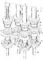
- FIG. 1is a front view of a device for providing wall ducts pursuant to the invention
- FIG. 2is a rear view of the device for providing wall ducts
- FIG. 3is a sectional view along the plane X of FIG. 1 ;
- FIG. 4is an exploded view of the device for providing wall ducts, without the wall;
- FIG. 5is a view of a retainer ring
- FIG. 6is view of a second design of the device for providing wall ducts
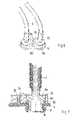
- FIG. 7is a sectional view of a part of the design shown in FIG. 6 ;
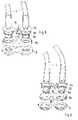
- FIG. 8is an exploded view from above the device shown in 6 ;
- FIG. 9is an exploded view from beneath the device shown in 6 .
- the device for providing wall ducts shown in FIG. 1serves to guide a bundle 2 of wiring 4 , here hydraulic lines, through a wall 3 of a body of a motor vehicle, not shown in detail.
- the wiring 4is equipped with cable couplers 5 , each of which has a first coupler half 6 and a second coupler half 7 . Sections 4 a , 4 b of the wiring 4 are connected with the coupler halves 6 , 7 .
- the first coupler halves 6are held together by means of a bracket 8 .
- the first coupler halves 6are held in the wall 3 with elastic rubber plugs 9 in a sealed and vibration-insulated fashion.
- a separate plug 9is provided for each cable coupler 5 ; this plug is held in the wall 3 in its own orifice 12 (see FIG. 3 ), respectively.
- the first coupler halves 6are laterally equipped with flattened areas 10 , which are seated between protrusions 11 of the bracket 8 so that the first coupler halves 6 are held in the bracket 8 in a way that prevents them from rotating.
- FIG. 3shows wiring 4 with a cable coupler 5 in the mounted state in a sectional view.
- the first section 4 a of the wiring 4here a tubing section—is connected with the first coupler half 6 by being placed on top.
- the second section 4 b of the wiring 4here a conduit section—is connected with the first coupler half 6 through the second coupler half 7 , which in the present example is designed as a union nut.
- the wall 3contains orifices 12 , of which here only one is shown as an example.
- the plug 9has been inserted, which for reasons of facilitating assembly is connected with the adjacent plug 9 via a strip 13 .
- the plug 9is held in the orifice 12 by means of a peripheral nose 14 , which engages behind the orifice 12 .
- the first coupler half 6is seated in the plug 9 with a cylindrical area 15 in such a way that the plug 9 forms a seal between the wall 3 and the first coupler half 6 .
- a peripheral nose 16is provided, which engages behind a step 17 provided in the plug. In this way, the first coupler half 6 is fastened in the plug 9 in a snap-fit fashion.
- the bracket 8is connected exclusively with the first coupler half 6 and contains an orifice 18 for receiving the first coupler half 6 .
- the edge of the orifice 18includes the protrusions 11 that support the flattened areas 10 of the first coupler half 6 and thus secure the first coupler half 6 against torsion.
- a peripheral groove 19is incorporated in the first coupler half 6 , and a retainer ring 20 is inserted in the groove.
- the retainer ring 20(shown in the top view in FIG. 5 ) is of a resilient material and contains a gap.
- the retainer ring 20When inserting the first coupler half 6 into the orifice 18 of the bracket 8 , the retainer ring 20 is compressed, supported by a taper 21 , in the orifice 18 and pressed into the groove 19 .
- the retainer ring 20can expand again and engage behind a step 22 , which is provided at the end of the orifice 18 .
- the retainer ring 20connects the first coupler half 6 and the bracket 8 with a positive fit.
- the retainer ring 20contains a taper corresponding on the outside to the taper 21 in order to facilitate insertion of the coupler half 6 and the associated compression of the retainer ring 20 .
- FIG. 4shows the individual components of the wall duct 1 without the wall 3 again in an exploded view.
- the parts 4 a of the wiringare equipped with the first coupler halves 6 .
- the first coupler halves 6are then pressed so far into the bracket 8 that the retainer rings 20 snap in.
- the conduit bundleis now combined into a unit at the end by the bracket 8 .
- the plugs 9are inserted into orifices 12 of the wall 3 .
- FIG. 6shows a second design of the device for providing wall conduits for the wiring 4 through a wall, of a body of a motor vehicle which is not shown here.
- the wiring 4in turn is equipped with cable couplers, of which here only the first coupler halves 6 a are shown. Contrary to the first design, here two first coupler halves 6 are combined into a group by a bracket 8 a ; a total of 2 brackets 8 a are required to combine a wire bundle consisting of four wiring portions 4 into groups of wirings 4 .
- the first coupler halves 6 aare held in the wall with elastic rubber plugs 9 in a sealed and vibration-insulated fashion, which in the present example are also combined into a group of two plugs 9 , corresponding to the first coupler halves 6 a . It is not necessary that the group of the first coupler halves 6 a contain the same number as the group of plugs 9 ; the group size is rather dependent upon the conditions encountered during assembly of the respective components.
- each cable coupler 5is equipped with its own plug 9 , which is held in its own orifice 12 (see FIG. 3 ) in the wall 3 .
- washer 23is held in a stationary position, for example by means of soldering, wherein the washers 23 each contain a nose 24 .
- Each nose 24engages the corresponding recess 25 , which is provided in the bracket 8 a , so that the first coupler halves 6 a are held in the bracket 8 a in a way that prevents torsion.
- FIG. 7depicts a main section through one of the first coupler halves 6 a of the second design. It is clearly visible that the nose 24 engages the recess 25 .
- the remaining design of the coupler halves 6 acorresponds to the first design, particularly the snap-fit of the coupler halves 6 a in the bracket 8 a with the help of the retainer ring 20 and the snap-fit of the coupler halves 6 a in the plug 9 by means of the peripheral noses 16 , which are incorporated on the coupler halves 6 a and engage behind a step 17 provided in the plug 9 .
- FIG. 8 and FIG. 9show the second design again in an exploded view.
Landscapes
- Engineering & Computer Science (AREA)
- General Engineering & Computer Science (AREA)
- Mechanical Engineering (AREA)
- Transportation (AREA)
- Quick-Acting Or Multi-Walled Pipe Joints (AREA)
- Installation Of Indoor Wiring (AREA)
- Snaps, Bayonet Connections, Set Pins, And Snap Rings (AREA)
- Connector Housings Or Holding Contact Members (AREA)
Abstract
Description
Claims (10)
Applications Claiming Priority (2)
| Application Number | Priority Date | Filing Date | Title |
|---|---|---|---|
| DE10233127.8 | 2002-07-20 | ||
| DE10233127ADE10233127C1 (en) | 2002-07-20 | 2002-07-20 | Supply line or cable gland for automobile assembled from 2 coupling halves with holder securing first coupling halves of at least 2 glands together to provide installation module |
Publications (2)
| Publication Number | Publication Date |
|---|---|
| US20040037627A1 US20040037627A1 (en) | 2004-02-26 |
| US7083202B2true US7083202B2 (en) | 2006-08-01 |
Family
ID=29432741
Family Applications (1)
| Application Number | Title | Priority Date | Filing Date |
|---|---|---|---|
| US10/622,643Expired - LifetimeUS7083202B2 (en) | 2002-07-20 | 2003-07-21 | Device for providing wall ducts for, and process of assembling, conduits, tubing or electric cables for motor vehicles |
Country Status (3)
| Country | Link |
|---|---|
| US (1) | US7083202B2 (en) |
| EP (1) | EP1382894B1 (en) |
| DE (2) | DE10233127C1 (en) |
Cited By (30)
| Publication number | Priority date | Publication date | Assignee | Title |
|---|---|---|---|---|
| US20050184087A1 (en)* | 1998-11-23 | 2005-08-25 | Zagars Raymond A. | Pump controller for precision pumping apparatus |
| US20070107707A1 (en)* | 2005-11-16 | 2007-05-17 | Arnulf Spieth | Crosstalk device for an exhaust system |
| US20070126233A1 (en)* | 2005-12-02 | 2007-06-07 | Iraj Gashgaee | O-ring-less low profile fittings and fitting assemblies |
| US20070128061A1 (en)* | 2005-12-02 | 2007-06-07 | Iraj Gashgaee | Fixed volume valve system |
| US20070127511A1 (en)* | 2005-12-02 | 2007-06-07 | James Cedrone | I/O systems, methods and devices for interfacing a pump controller |
| US20070206436A1 (en)* | 2006-03-01 | 2007-09-06 | Niermeyer J K | System and method for controlled mixing of fluids |
| US20070217442A1 (en)* | 2006-03-01 | 2007-09-20 | Mcloughlin Robert F | System and method for multiplexing setpoints |
| US20090008928A1 (en)* | 2006-01-05 | 2009-01-08 | Alfred Kaercher Gmbh & Co. Kg | Plug-in part for a plug connector arrangement |
| US20090008927A1 (en)* | 2006-01-05 | 2009-01-08 | Alfred Kaercher Gmbh & Co. Kg | Coupling part for a plug connector arrangement |
| US20100001144A1 (en)* | 2006-12-01 | 2010-01-07 | Bertil Lundgren | Holding means for a hydraulic coupling |
| US20100066076A1 (en)* | 2006-12-01 | 2010-03-18 | Bertil Lundgren | Hydraulic connection |
| US7850431B2 (en) | 2005-12-02 | 2010-12-14 | Entegris, Inc. | System and method for control of fluid pressure |
| US7878765B2 (en) | 2005-12-02 | 2011-02-01 | Entegris, Inc. | System and method for monitoring operation of a pump |
| US20110037252A1 (en)* | 2008-04-29 | 2011-02-17 | Josef Brandt | Connection device for fluid lines in the region of a wall duct and wall element |
| US7897196B2 (en) | 2005-12-05 | 2011-03-01 | Entegris, Inc. | Error volume system and method for a pump |
| US20110103882A1 (en)* | 2009-11-03 | 2011-05-05 | Mcdavid Bradford A | Pipe flange guide shroud |
| US8025486B2 (en) | 2005-12-02 | 2011-09-27 | Entegris, Inc. | System and method for valve sequencing in a pump |
| US8029247B2 (en) | 2005-12-02 | 2011-10-04 | Entegris, Inc. | System and method for pressure compensation in a pump |
| US8083498B2 (en) | 2005-12-02 | 2011-12-27 | Entegris, Inc. | System and method for position control of a mechanical piston in a pump |
| US8087429B2 (en) | 2005-11-21 | 2012-01-03 | Entegris, Inc. | System and method for a pump with reduced form factor |
| US8172546B2 (en) | 1998-11-23 | 2012-05-08 | Entegris, Inc. | System and method for correcting for pressure variations using a motor |
| US8292598B2 (en) | 2004-11-23 | 2012-10-23 | Entegris, Inc. | System and method for a variable home position dispense system |
| US20130001942A1 (en)* | 2011-06-30 | 2013-01-03 | Bryan Fulmer | Poka-yoke for a set of hydraulic fittings |
| US8753097B2 (en) | 2005-11-21 | 2014-06-17 | Entegris, Inc. | Method and system for high viscosity pump |
| US9631611B2 (en) | 2006-11-30 | 2017-04-25 | Entegris, Inc. | System and method for operation of a pump |
| USD819186S1 (en)* | 2011-12-12 | 2018-05-29 | Hs R & A Co., Ltd. | Connector for double pipe heat exchanger |
| US20210223128A1 (en) | 2020-01-22 | 2021-07-22 | DropWater Solutions | Multi-bandwidth communication for fluid distribution network |
| US11293430B2 (en)* | 2020-01-22 | 2022-04-05 | DropWater Solutions | Smart pump controller |
| US11792885B2 (en) | 2020-01-22 | 2023-10-17 | DropWater Solutions | Wireless mesh for fluid distribution network |
| US20240200704A1 (en)* | 2022-12-15 | 2024-06-20 | Illinois Tool Works Inc. | Multi-Connector |
Families Citing this family (14)
| Publication number | Priority date | Publication date | Assignee | Title |
|---|---|---|---|---|
| US20060038074A1 (en) | 2004-05-07 | 2006-02-23 | Buhr Theo D | Connecting element for connecting a conduit system to cooling aggregates in aircraft cabins |
| DE102004023242B4 (en)* | 2004-05-07 | 2007-06-14 | Airbus Deutschland Gmbh | Connection element for connecting two line elements of a guided through a separator to the cabin of an aircraft conduit system |
| DE102004033567A1 (en)* | 2004-07-09 | 2006-01-26 | Leybold Optics Gmbh | Consumer supply connection system for implementing electric output/power and a fluid through a wall of a chamber in a vacuum chamber supplies a consumer with power via a supply module |
| DE202007012400U1 (en)* | 2007-04-19 | 2008-08-21 | Voss Automotive Gmbh | Connecting device for media lines in the region of a wall duct and wall element |
| WO2009041865A1 (en)* | 2007-09-26 | 2009-04-02 | Volvo Lastvagnar Ab | A drive unit for a heavy vehicle |
| DE102007051836A1 (en)† | 2007-10-30 | 2009-05-14 | Leoni Bordnetz-Systeme Gmbh | Cable set, in particular a high-voltage cable set for a motor vehicle, and a device for carrying an electrical cable and for connecting a shield of the cable |
| DE102008014291A1 (en) | 2008-03-14 | 2009-09-24 | Agco Gmbh | Vibration decoupling device for hydraulics |
| DE102008029468B4 (en) | 2008-06-20 | 2011-01-13 | Airbus Operations Gmbh | Interface element, aircraft interior equipment component and method for assembling an aircraft interior equipment component |
| FR2938039A1 (en)* | 2008-10-31 | 2010-05-07 | Peugeot Citroen Automobiles Sa | Sealed connection assembly for connecting connector to e.g. wall of brake control enclosure of pneumatic brake booster in vehicle, has sleeve including outer wall with notches ensuring sealed anchoring of sleeve on endpiece |
| DE202009009807U1 (en) | 2009-07-17 | 2009-09-24 | Wiska Hoppmann & Mulsow Gmbh | Tamper-proof cable entry |
| DE102013214611A1 (en)* | 2013-07-26 | 2015-01-29 | Bayerische Motoren Werke Aktiengesellschaft | Coupling system for forming at least one arranged in a vehicle fluid-carrying line |
| DE102018205611A1 (en)* | 2018-04-13 | 2019-10-17 | Volkswagen Aktiengesellschaft | Housing with a cable feedthrough element and method for attaching a sensor cable to a housing of a motor vehicle steering |
| US12202446B2 (en) | 2019-09-12 | 2025-01-21 | A. Raymond Et Cie | Flow control valve and system for cleaning a vehicle surface |
| EP3792535A1 (en) | 2019-09-12 | 2021-03-17 | A. Raymond et Cie | Flow control valve and system for cleaning a vehicle surface |
Citations (12)
| Publication number | Priority date | Publication date | Assignee | Title |
|---|---|---|---|---|
| US3869153A (en)* | 1974-07-22 | 1975-03-04 | Gen Motors Corp | Double tube mounting assembly |
| US3869152A (en)* | 1974-03-27 | 1975-03-04 | Gen Motors Corp | Tube mounting assembly |
| DE3226475A1 (en) | 1982-07-15 | 1984-01-19 | Daimler-Benz Ag, 7000 Stuttgart | SEALING WALL PIPE FOR PIPELINES, HOSES OR ELECTRIC CABLES FOR MOTOR VEHICLES |
| US4482172A (en) | 1981-07-09 | 1984-11-13 | Eaton Corporation | Dual sealing fluid connector |
| US4630847A (en)* | 1984-10-05 | 1986-12-23 | Colder Products Company | Multiple tube connector |
| US4893845A (en)* | 1988-04-18 | 1990-01-16 | Proprietary Technology, Inc. | Firewall heater line adapter |
| US5297820A (en)* | 1991-11-19 | 1994-03-29 | Kreuzer Gmbh & Co. Ohg | Line coupling system |
| US5865474A (en)* | 1996-04-26 | 1999-02-02 | Tokai Rubber Industries, Ltd. | Cluster hose-pipe connector device capable of concurrent connection of hoses and pipes by single relative movement of connector holder and pipe holder |
| US5951059A (en)* | 1996-07-24 | 1999-09-14 | Tokai Rubber Industries Ltd. | Tube connector device having connector holder made of elastomer |
| US6035891A (en)* | 1996-07-19 | 2000-03-14 | Hawkins, Jr.; Albert D. | Emergency air system |
| US6520545B2 (en)* | 2000-12-08 | 2003-02-18 | Sartorius Ag | Fluid connection adapter assembly |
| US6609732B1 (en)* | 2002-02-01 | 2003-08-26 | General Motors Corporation | Quick connect multi-hose connector |
- 2002
- 2002-07-20DEDE10233127Apatent/DE10233127C1/ennot_activeExpired - Fee Related
- 2003
- 2003-04-30EPEP03009688Apatent/EP1382894B1/ennot_activeExpired - Lifetime
- 2003-04-30DEDE50311821Tpatent/DE50311821D1/ennot_activeExpired - Lifetime
- 2003-07-21USUS10/622,643patent/US7083202B2/ennot_activeExpired - Lifetime
Patent Citations (12)
| Publication number | Priority date | Publication date | Assignee | Title |
|---|---|---|---|---|
| US3869152A (en)* | 1974-03-27 | 1975-03-04 | Gen Motors Corp | Tube mounting assembly |
| US3869153A (en)* | 1974-07-22 | 1975-03-04 | Gen Motors Corp | Double tube mounting assembly |
| US4482172A (en) | 1981-07-09 | 1984-11-13 | Eaton Corporation | Dual sealing fluid connector |
| DE3226475A1 (en) | 1982-07-15 | 1984-01-19 | Daimler-Benz Ag, 7000 Stuttgart | SEALING WALL PIPE FOR PIPELINES, HOSES OR ELECTRIC CABLES FOR MOTOR VEHICLES |
| US4630847A (en)* | 1984-10-05 | 1986-12-23 | Colder Products Company | Multiple tube connector |
| US4893845A (en)* | 1988-04-18 | 1990-01-16 | Proprietary Technology, Inc. | Firewall heater line adapter |
| US5297820A (en)* | 1991-11-19 | 1994-03-29 | Kreuzer Gmbh & Co. Ohg | Line coupling system |
| US5865474A (en)* | 1996-04-26 | 1999-02-02 | Tokai Rubber Industries, Ltd. | Cluster hose-pipe connector device capable of concurrent connection of hoses and pipes by single relative movement of connector holder and pipe holder |
| US6035891A (en)* | 1996-07-19 | 2000-03-14 | Hawkins, Jr.; Albert D. | Emergency air system |
| US5951059A (en)* | 1996-07-24 | 1999-09-14 | Tokai Rubber Industries Ltd. | Tube connector device having connector holder made of elastomer |
| US6520545B2 (en)* | 2000-12-08 | 2003-02-18 | Sartorius Ag | Fluid connection adapter assembly |
| US6609732B1 (en)* | 2002-02-01 | 2003-08-26 | General Motors Corporation | Quick connect multi-hose connector |
Cited By (60)
| Publication number | Priority date | Publication date | Assignee | Title |
|---|---|---|---|---|
| US7476087B2 (en) | 1998-11-23 | 2009-01-13 | Entegris, Inc. | Pump controller for precision pumping apparatus |
| US20050184087A1 (en)* | 1998-11-23 | 2005-08-25 | Zagars Raymond A. | Pump controller for precision pumping apparatus |
| US8172546B2 (en) | 1998-11-23 | 2012-05-08 | Entegris, Inc. | System and method for correcting for pressure variations using a motor |
| US9617988B2 (en) | 2004-11-23 | 2017-04-11 | Entegris, Inc. | System and method for variable dispense position |
| US8814536B2 (en) | 2004-11-23 | 2014-08-26 | Entegris, Inc. | System and method for a variable home position dispense system |
| US8292598B2 (en) | 2004-11-23 | 2012-10-23 | Entegris, Inc. | System and method for a variable home position dispense system |
| US20070107707A1 (en)* | 2005-11-16 | 2007-05-17 | Arnulf Spieth | Crosstalk device for an exhaust system |
| US7866709B2 (en)* | 2005-11-16 | 2011-01-11 | J. Eberspaecher Gmbh & Co. Kg | Crosstalk device for an exhaust system |
| US8753097B2 (en) | 2005-11-21 | 2014-06-17 | Entegris, Inc. | Method and system for high viscosity pump |
| US8087429B2 (en) | 2005-11-21 | 2012-01-03 | Entegris, Inc. | System and method for a pump with reduced form factor |
| US9399989B2 (en) | 2005-11-21 | 2016-07-26 | Entegris, Inc. | System and method for a pump with onboard electronics |
| US8651823B2 (en) | 2005-11-21 | 2014-02-18 | Entegris, Inc. | System and method for a pump with reduced form factor |
| US20070128061A1 (en)* | 2005-12-02 | 2007-06-07 | Iraj Gashgaee | Fixed volume valve system |
| US8083498B2 (en) | 2005-12-02 | 2011-12-27 | Entegris, Inc. | System and method for position control of a mechanical piston in a pump |
| US9025454B2 (en) | 2005-12-02 | 2015-05-05 | Entegris, Inc. | I/O systems, methods and devices for interfacing a pump controller |
| US8870548B2 (en) | 2005-12-02 | 2014-10-28 | Entegris, Inc. | System and method for pressure compensation in a pump |
| US20070127511A1 (en)* | 2005-12-02 | 2007-06-07 | James Cedrone | I/O systems, methods and devices for interfacing a pump controller |
| US8678775B2 (en) | 2005-12-02 | 2014-03-25 | Entegris, Inc. | System and method for position control of a mechanical piston in a pump |
| US8662859B2 (en) | 2005-12-02 | 2014-03-04 | Entegris, Inc. | System and method for monitoring operation of a pump |
| US7850431B2 (en) | 2005-12-02 | 2010-12-14 | Entegris, Inc. | System and method for control of fluid pressure |
| WO2007067343A3 (en)* | 2005-12-02 | 2008-12-04 | Entegris Inc | O-ring-less low profile fittings and fitting assemblies |
| US8382444B2 (en) | 2005-12-02 | 2013-02-26 | Entegris, Inc. | System and method for monitoring operation of a pump |
| US9816502B2 (en) | 2005-12-02 | 2017-11-14 | Entegris, Inc. | System and method for pressure compensation in a pump |
| US9309872B2 (en) | 2005-12-02 | 2016-04-12 | Entegris, Inc. | System and method for position control of a mechanical piston in a pump |
| US7878765B2 (en) | 2005-12-02 | 2011-02-01 | Entegris, Inc. | System and method for monitoring operation of a pump |
| US7940664B2 (en) | 2005-12-02 | 2011-05-10 | Entegris, Inc. | I/O systems, methods and devices for interfacing a pump controller |
| US20070126233A1 (en)* | 2005-12-02 | 2007-06-07 | Iraj Gashgaee | O-ring-less low profile fittings and fitting assemblies |
| US8025486B2 (en) | 2005-12-02 | 2011-09-27 | Entegris, Inc. | System and method for valve sequencing in a pump |
| US8029247B2 (en) | 2005-12-02 | 2011-10-04 | Entegris, Inc. | System and method for pressure compensation in a pump |
| US9262361B2 (en) | 2005-12-02 | 2016-02-16 | Entegris, Inc. | I/O systems, methods and devices for interfacing a pump controller |
| US7547049B2 (en)* | 2005-12-02 | 2009-06-16 | Entegris, Inc. | O-ring-less low profile fittings and fitting assemblies |
| US7897196B2 (en) | 2005-12-05 | 2011-03-01 | Entegris, Inc. | Error volume system and method for a pump |
| US20100176590A1 (en)* | 2006-01-05 | 2010-07-15 | Alfred Kaercher Gmbh & Co. Kg | Plug-in part for a plug connector arrangement |
| US20090008928A1 (en)* | 2006-01-05 | 2009-01-08 | Alfred Kaercher Gmbh & Co. Kg | Plug-in part for a plug connector arrangement |
| US20090008927A1 (en)* | 2006-01-05 | 2009-01-08 | Alfred Kaercher Gmbh & Co. Kg | Coupling part for a plug connector arrangement |
| US7708320B2 (en)* | 2006-01-05 | 2010-05-04 | Alfred Kaercher Gmbh & Co. Kg | Plug-in part for a plug connector arrangement |
| US7770940B2 (en)* | 2006-01-05 | 2010-08-10 | Alfred Kaercher Gmbh & Co. Kg | Coupling part for a plug connector arrangement |
| US8485228B2 (en) | 2006-01-05 | 2013-07-16 | Alfred Kaercher Gmbh & Co. Kg | Plug-in part for a plug connector arrangement |
| US7494265B2 (en) | 2006-03-01 | 2009-02-24 | Entegris, Inc. | System and method for controlled mixing of fluids via temperature |
| US20070206436A1 (en)* | 2006-03-01 | 2007-09-06 | Niermeyer J K | System and method for controlled mixing of fluids |
| US20070217442A1 (en)* | 2006-03-01 | 2007-09-20 | Mcloughlin Robert F | System and method for multiplexing setpoints |
| US7946751B2 (en) | 2006-03-01 | 2011-05-24 | Entegris, Inc. | Method for controlled mixing of fluids via temperature |
| US7684446B2 (en) | 2006-03-01 | 2010-03-23 | Entegris, Inc. | System and method for multiplexing setpoints |
| US9631611B2 (en) | 2006-11-30 | 2017-04-25 | Entegris, Inc. | System and method for operation of a pump |
| US8585098B2 (en)* | 2006-12-01 | 2013-11-19 | Nordhydraulic Ab | Hydraulic connection |
| US8262136B2 (en)* | 2006-12-01 | 2012-09-11 | Nordhydraulic Ab | Holding means for a hydraulic coupling |
| US20100001144A1 (en)* | 2006-12-01 | 2010-01-07 | Bertil Lundgren | Holding means for a hydraulic coupling |
| US20100066076A1 (en)* | 2006-12-01 | 2010-03-18 | Bertil Lundgren | Hydraulic connection |
| US20110037252A1 (en)* | 2008-04-29 | 2011-02-17 | Josef Brandt | Connection device for fluid lines in the region of a wall duct and wall element |
| US8511716B2 (en)* | 2008-04-29 | 2013-08-20 | Voss Automotive Gmbh | Connection device for fluid lines in the region of a wall duct and wall element |
| US20110103882A1 (en)* | 2009-11-03 | 2011-05-05 | Mcdavid Bradford A | Pipe flange guide shroud |
| US8511717B2 (en)* | 2011-06-30 | 2013-08-20 | Harley-Davidson Motor Company Group, LLC | Poka-yoke for a set of hydraulic fittings |
| US20130001942A1 (en)* | 2011-06-30 | 2013-01-03 | Bryan Fulmer | Poka-yoke for a set of hydraulic fittings |
| JP2013015220A (en)* | 2011-06-30 | 2013-01-24 | Harley-Davidson Motor Co Group Llc | Hydraulic manifold assembly |
| USD819186S1 (en)* | 2011-12-12 | 2018-05-29 | Hs R & A Co., Ltd. | Connector for double pipe heat exchanger |
| US20210223128A1 (en) | 2020-01-22 | 2021-07-22 | DropWater Solutions | Multi-bandwidth communication for fluid distribution network |
| US11293430B2 (en)* | 2020-01-22 | 2022-04-05 | DropWater Solutions | Smart pump controller |
| US11792885B2 (en) | 2020-01-22 | 2023-10-17 | DropWater Solutions | Wireless mesh for fluid distribution network |
| US11959816B2 (en) | 2020-01-22 | 2024-04-16 | DropWater Solutions | Multi-bandwidth communication for fluid distribution network |
| US20240200704A1 (en)* | 2022-12-15 | 2024-06-20 | Illinois Tool Works Inc. | Multi-Connector |
Also Published As
| Publication number | Publication date |
|---|---|
| EP1382894B1 (en) | 2009-08-19 |
| EP1382894A2 (en) | 2004-01-21 |
| US20040037627A1 (en) | 2004-02-26 |
| EP1382894A3 (en) | 2004-03-31 |
| DE50311821D1 (en) | 2009-10-01 |
| DE10233127C1 (en) | 2003-12-11 |
Similar Documents
| Publication | Publication Date | Title |
|---|---|---|
| US7083202B2 (en) | Device for providing wall ducts for, and process of assembling, conduits, tubing or electric cables for motor vehicles | |
| US20070137884A1 (en) | Motor vehicle wiring harness having a grommet between occupant and engine compartments | |
| US5685598A (en) | Mount structure for an instrument panel | |
| US5716044A (en) | Vehicle door and wire harness arrangement | |
| US9647438B2 (en) | Sealing grommet assembly with integral wire channel | |
| EP0865131A1 (en) | Electrical connection box assembly | |
| JP5416482B2 (en) | Wire harness wiring body, wire harness wiring unit, and method of assembling wire harness wiring unit | |
| US20190344731A1 (en) | Wire Harness, Component Module for Wire Harness, and Vehicle Component | |
| JP2001176346A (en) | Seal mechanism of passage part of passing-through things in partition portion of vehicle | |
| US6240903B1 (en) | Wiring arrangement for engine fuel injector | |
| WO2011155088A1 (en) | Grommet | |
| EP0476654A1 (en) | A wiring structure for interior units | |
| US20070039751A1 (en) | Motor vehicle wiring harness having a grommet between occupant and engine compartments | |
| US10974774B2 (en) | Air guide device for a vehicle | |
| CN1376119A (en) | Device for fixing a functional element to a motor vehicle body | |
| CN214044808U (en) | A fixed knot constructs that is used for line inside and outside car | |
| JP7613117B2 (en) | Grommet device and wire harness | |
| JP4218203B2 (en) | Terminal protection device for vehicles | |
| JP2023048183A (en) | Front structure of vehicle | |
| KR102718993B1 (en) | Wiring grommet | |
| KR100315059B1 (en) | Structure assembling a wire &pipe(brake &clutch) of vehicle | |
| JP2725082B2 (en) | Connector mounting structure | |
| JP2006290191A (en) | Vehicle back door module | |
| JPH0282469A (en) | Installation structure of wiring harness and its electrical connection box to vehicle body, etc. | |
| CN119858513A (en) | Automobile EMS rubber protection device and installation method thereof |
Legal Events
| Date | Code | Title | Description |
|---|---|---|---|
| AS | Assignment | Owner name:DR. ING. H.C.F. PORSCHE AKTIENGESELLSCHAFT, GERMAN Free format text:ASSIGNMENT OF ASSIGNORS INTEREST;ASSIGNORS:EBERLE, WILFRIED;KLATTE, HEINER;REEL/FRAME:014318/0103 Effective date:20030716 | |
| STCF | Information on status: patent grant | Free format text:PATENTED CASE | |
| AS | Assignment | Owner name:DR. ING. H.C.F. PORSCHE AKTIENGESELLSCHAFT (COMPAN Free format text:MERGER;ASSIGNOR:DR. ING. H.C.F. PORSCHE AKTIENGESELLSCHAFT (COMPANY NUMBER 5211);REEL/FRAME:021040/0147 Effective date:20071113 | |
| FPAY | Fee payment | Year of fee payment:4 | |
| AS | Assignment | Owner name:PORSCHE ZWISCHENHOLDING GMBH, GERMANY Free format text:MERGER;ASSIGNOR:DR. ING. H.C.F. PORSCHE AKTIENGESELLSCHAFT;REEL/FRAME:025227/0699 Effective date:20091125 Owner name:DR. ING. H.C.F. PORSCHE AKTIENGESELLSCHAFT, GERMAN Free format text:CHANGE OF NAME;ASSIGNOR:PORSCHE ZWISCHENHOLDING GMBH;REEL/FRAME:025227/0747 Effective date:20091130 | |
| FPAY | Fee payment | Year of fee payment:8 | |
| MAFP | Maintenance fee payment | Free format text:PAYMENT OF MAINTENANCE FEE, 12TH YEAR, LARGE ENTITY (ORIGINAL EVENT CODE: M1553) Year of fee payment:12 |