US7083156B2 - Automatic proximity faucet with override control system and method - Google Patents
Automatic proximity faucet with override control system and methodDownload PDFInfo
- Publication number
- US7083156B2 US7083156B2US10/757,839US75783904AUS7083156B2US 7083156 B2US7083156 B2US 7083156B2US 75783904 AUS75783904 AUS 75783904AUS 7083156 B2US7083156 B2US 7083156B2
- Authority
- US
- United States
- Prior art keywords
- coupled
- arm
- pilot valve
- hands
- sensor
- Prior art date
- Legal status (The legal status is an assumption and is not a legal conclusion. Google has not performed a legal analysis and makes no representation as to the accuracy of the status listed.)
- Expired - Lifetime
Links
Images


Classifications
- E—FIXED CONSTRUCTIONS
- E03—WATER SUPPLY; SEWERAGE
- E03C—DOMESTIC PLUMBING INSTALLATIONS FOR FRESH WATER OR WASTE WATER; SINKS
- E03C1/00—Domestic plumbing installations for fresh water or waste water; Sinks
- E03C1/02—Plumbing installations for fresh water
- E03C1/04—Water-basin installations specially adapted to wash-basins or baths
- E03C1/0404—Constructional or functional features of the spout
- E—FIXED CONSTRUCTIONS
- E03—WATER SUPPLY; SEWERAGE
- E03C—DOMESTIC PLUMBING INSTALLATIONS FOR FRESH WATER OR WASTE WATER; SINKS
- E03C1/00—Domestic plumbing installations for fresh water or waste water; Sinks
- E03C1/02—Plumbing installations for fresh water
- E03C1/05—Arrangements of devices on wash-basins, baths, sinks, or the like for remote control of taps
- E03C1/055—Electrical control devices, e.g. with push buttons, control panels or the like
- E03C1/057—Electrical control devices, e.g. with push buttons, control panels or the like touchless, i.e. using sensors
Definitions
- This inventionrelates to a system and a method that controls fluid flow, and more particularly, to a system and a method that controls fluid flow through a faucet.
- Some faucetssuffer from the effects of cross-contamination.
- the transfer of germs from one user to anothercan occur when a user touches a handle that enables the flow of water.
- Cross-contaminationmay result from hand-to-mouth, hand-to-nose, and hand-to-eye contact.
- An awareness of such contaminationcan create a reluctance to touch a fixture, which does not promote or preserve good hygiene.
- some faucetsuse hands-free methods to control water flow.
- a passive sensoris used to detect a user. Once a user is detected, water flows for a fixed period of time.
- a problem with some hands-free faucetsis their inability to be turned on or off or to sustain a continuous water flow when a user is not detected. Because all sources of water possess naturally occurring contaminants, sometimes it is necessary to flush faucets and waterlines. Requiring a user to stand in front of a spout to flush a hands-free faucet can be time consuming and costly. The short periods of time that these hands-free faucets allow continuous water flow can also be inadequate as short periods of uninterrupted water flow will not always purge faucets of contaminants. Ironically, some automatic faucets used to prevent the spread of germs are more difficult to purge of water borne bacteria because a user is required to normally cause flow.
- a hands-free embodimentcomprises a sensor, a motor a pilot valve, a gear train, an arm, and an override control.
- the motoropens the pilot valve when an activation signal is received from the sensor.
- the armis coupled to the gear train, and the override control is coupled to the arm.
- the override controlis capable of moving the arm between a locked and unlocked configuration.
- FIG. 1is a front view of a hands-free embodiment.
- FIG. 2is a partial cutaway view of a spout mounted to a surface in FIG. 1 .
- FIG. 3is a partial cutaway view of an alternative spout mounted to a surface in FIG. 1 .
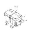
- FIG. 4is a top perspective view of a dual valve housing.
- FIG. 5is a top perspective view of an alternative mixing and valve housing.
- FIG. 6is a front cutaway view of the mixing and valve housing taken along line I—I in FIG. 5 .
- FIG. 7is a top exploded view of a valve assembly.
- FIG. 8is a partial side cutaway view of FIG. 7 .
- FIG. 9is a flow diagram of a manual override method.
- the presently preferred system and methodprovide users with a hands-free system and method for controlling fluid flow through a spout.
- the preferred system and methodallows for continuous flow without actuating a handle or a button.
- an override controlcan turn on a faucet and/or sustain a continuous flow even when a user is not detected.
- a continuous flow through a spoutwill flush a faucet and can eliminate contaminants.
- FIG. 1shows a front view of a hands-free embodiment.
- the embodimentcomprises a spout 102 , a valve housing 104 , and a mixing housing 106 .
- the spout 102directs and/or regulates the flow of a fluid from a reservoir such as a pipe or a drum.
- the mixing housing 106positioned below the spout 102 , includes multiple fitting illustrated as male compression fitting emanating from about the nine, twelve, and three o'clock positions of the mixing housing 106 .
- the hands-free embodimentincludes a sensor.
- an activation signalinitiates continuous fluid flow.
- the hands-free embodimentshuts off fluid flow which reduces the possibility of accidental flooding when the hand-free system and method are not in an open mode.
- the spoutalso comprises the sensor 108 .
- the sensor 108can be a proximity, motion, an infrared, or a body heat sensor, and/or any other device that detects or measures something by converting one form of energy into another (e.g., into an electrical or an optical energy, for example).
- the sensitivity range of the sensor 108is adjustable.
- the sensor 108comprises logic that conditions the activation signal and automatically adjusts to its surroundings.
- the sensor 108can compensate for changes in its environment including changes in humidity, temperature or contact with objects such as wet paper towels, for example, and still maintain a desired sensitivity.
- the illustrated sensor 108also functions as a spout 102
- the sensor 108can be a separate element positioned adjacent to or away from the spout 102 .
- an outlet 110couples the valve housing 104 to the spout 102 .
- an aerator 112is threaded to the spout 102 .
- the aerator 112maintains fluid pressure by mixing air into the fluid.
- a threaded fittingcouples the spout 102 to a surface 114 .
- the spout 102can have many shapes. Besides the rectangular and circular cross-sections that are shown, the spout 102 encompasses many other designs that vary by shape, height, accessories (e.g., use of built in or attachable filters, for example), color, etc.
- fluidcan flow through the entire interior volume 202 of the spout 102 .
- fluidcan flow through a portion of the spout 102 .
- fluid flowis restricted to a pipe 302 such as a copper tube or rubber hose enclosed by the spout 102 .
- a spout bracket 304couples the pipe 302 to the spout 102 .
- the spout bracket 304can form a portion of the lower arcuate surface of the spout 102 .
- the valve and mixing housing 104 and 106can comprise a unitary housing or separate housing assemblies joined by straps and secured by the cover screws.
- an override control 402is coupled to the valve housing 104 .
- the override control 402is a mechanism that activates and/or sustains fluid flow.
- the override controlis a mechanism or logic that can activate or prevent fluid flow, and/or allow continuous fluid flow beyond a predetermined or programmed period initiated by an output of the sensor 108 .
- the mixing housing 106encloses a mixing valve 602 .
- the mixing valve 602blends fluids from more than one source. In this embodiment, hot and cold water are blended to a pre-set temperature. Although no adjustments are shown, some embodiments allow a user to preset, or adjust, the temperature of the water being dispensed from the spout 102 .
- the mixing housing 106is coupled to the valve housing 104 by a valve adapter 502 .
- the valve adapter 502comprises a cylinder having a keyway 702 and threads 704 at one end as shown in FIG. 7 .
- a valve pin 706seats within the keyway 702 providing a seal between the valve housing 104 and the valve adapter 502 .
- An O-ring 708preferably provides a positive fluid tight seal between the valve housing 104 and the valve adapter 502 .
- An axial filter 710can be disposed within the valve plug 502 to separate fluids from particulate matter flowing from the mixing valve 602 to the valve housing 104 or valve assembly.
- the filter 710 shown in figure 7comprises a mesh or a semi-permeable membrane. In another embodiment other materials that selectively pass fluids without passing some or all contaminants can be used as a filter.
- the valve housing 104encloses a motor 604 .
- the motor 604is mechanically coupled to a cam 606 .
- the cam 606is the multiply curved wheel mounted to the motor 604 through a shaft and gear train 712 .
- the cam 606 and a cam follower 608translate the rotational motion of the shaft into a substantially linear displacement that opens and closes a diaphragm 610 .
- the cam 606has an offset pivot that produces a variable or reciprocating motion within a cutout portion 612 of the cam follower 608 .
- the cam follower 608 shown in the “P-shaped” cross-sectionis moved by the cam within an orifice, which engages a rod like element.
- the rod like elementcomprises a pilot 614 that slides through an orifice 616 . Movement of the pilot 614 can break the closure between the inlet 618 and the outlet port 620 by moving the diaphragm 610 .
- a bias plate 622couples the diaphragm 610 to the pilot 614 .
- the bias plate 622 illustrated in a rectangular cross-section with projecting legs at its endsdistributes the axial pressure of the pilot 614 across an inlet surface of the diaphragm 610 .
- the diaphragm 610is coupled between the legs of the bias plate 622 by a connector 624 .
- the connector 624comprises a threaded member.
- the connector 624comprises an adhesive or a fastener.
- the diaphragm 610seats against a seating ring or seating surface 802 which seals the inlet port 618 from an outlet port 620 .
- the fluid and the pilot 614exert a positive pressure against the diaphragm 610 which assures a fluid tight seal.
- the pilot pressureis released the fluid pressure acting on the underside of the diaphragm 610 exceeds the seating pressure of the fluid pressing against the inlet surface of the diaphragm 610 .
- the diaphragm 610is forced up which opens the valve and allows for a continuous angled fluid flow.
- a fluid backpressurebuilds up on the inlet surface of the diaphragm 610 .
- the pilot and fluid backpressureforce the diaphragm 610 to seat, which in turn, stops the flow.
- the build up of backpressurepreferably occurs after the sensor no longer senses an appendage such as a hand, when the hands-free embodiment is in an automatic mode.
- the diaphragm 610which is the part of a valve mechanism that opens or closes the outlet port 622 , is wedge shaped. Some diaphragms 610 , however, can have a uniform thickness throughout or have many other shapes depending on the contour of the seating surface.
- FIG. 7shows a top exploded view of the valve assembly.
- a housing 104encloses a pilot valve assembly 714 and logic 716 .
- the logic 716interfaces the sensor 108 to the motor 604 .
- a compression of a molding 718 that outlines the lower edges of the housing cover 720causes a fluid tight seal to form around the inner and outer edges of the housing 104 .
- orifices 722 passing through the sides of the housing cover 720allow power to be sourced to the logic 716 and the motor 604 .
- battery packscan provide the primary power in this embodiment, hardwired alternatives with or without battery backups can also be used.
- low-voltage direct current power supplies or battery packsdrive a Direct Current motor and the logic.
- the pilot assembly 714 of the hands-free embodiment shown in FIG. 7is preferably comprised of the motor 604 , its shaft, the cam 606 , the cam follower 608 , the gear train 712 , and the pilot 614 .
- the O-ring 626 shown in FIG. 6makes a fluid tight seal between the motor 664 , its shaft, the cam 606 , cam follower 608 , the gear train 712 and a portion of the pilot 614 .
- the sealis located approximately three quarters down the length of the pilot valve assembly 714 .
- the hands-free embodimentalso includes an override control 402 that allows for continuous fluid flow.
- the override control 402 shown in FIG. 7is comprised of an override arm 724 .
- the override arm 724is fitted to a stem 726 comprised of a cylindrical projection connected to an outward face of one of the interconnected gears that form the gear train 712 .
- the stem 726is a part of a spur gear 728 having teeth radially arrayed on its rim parallel to its axis of rotation.
- a strike plate 730is coupled to the spur gear 728 by a shaft 732 that transmits power through the gear train 712 to the pilot 614 .
- the strike plate 730can interrupt the rotation of the shaft 732 and gear train 712 when the pilot 614 reaches a top or a bottom limit of travel.
- contact between the stem 726 and the convex surfaces of the strike plate 730establish the top and bottom limits of travel.
- the stem 726strikes a positive moderate sloping side surface 734 of the strike plate 730 and at another end the stem 726 strikes a substantially linear side surface 736 .
- an override knob 738 shown in figure 7is coupled to an override shaft 724 projecting from the override arm.
- the gear train 712rotates until a projection 740 on the override arm 724 strikes stem 726 the strike plate 730 .
- the pressure on the underside of the diaphragm 610will be greater than that on the inlet side, and the valve will be open.
- FIG. 7shows a hands-free embodiment that also encompasses a closed mode. In this mode, the valve is closed and the motor 604 will not respond to the sensor 108 . While such a control has many configurations, in one embodiment this control can be an interruption of the ground or power source to the motor 604 by the opening of an electronic, mechanical, and/or an electro-mechanical switch. Only a turning of the override knob 738 to the automatic or open mode will allow fluid to flow through the outlet port 620 .
- the operation of the open modebegins when an open selection is made at act 902 . Once selected, fluid flows unaffected by any pre-set or predetermined periods of time. Fluid flow is shut off by either an automatic or manual selection at act 904 .
- a manual modethe detection of a user biases the motor to rotate the gear train 712 which is already in an open position. When a user is no longer detected, the motor rotates the gear train 712 and the override knob 738 to the auto position shutting off fluid flow at act 908 .
- the sensor 108initiates a fluid flow when a user is detected in a field of view at act 906 .
- an electronic switch electrically connected to the sensor 108actuates the motor 604 at act 910 .
- the motorrotates the gear train 712 , cam 606 , and the cam follower 608 from an active state of continuous fluid flow to an inactive state of no fluid flow at acts 912 and 914 .
- fluidwill again flow when a user is again detected in the field of view.
- the detentis not limited to override control disclosed.
- the detentcan be an electronic detent, comprising a programmable timing device that sustains an uninterrupted fluid flow for an extended period of time.
- the systemcan also embrace other mechanical detents, for example, that lock movement of the motor 604 or the gear train 712 and/or the shaft 732 .
- One such embodimentcan comprise a catch lever that seats within a channel of the spur gear 728 of the gear train 712 .
- the torque of the motor 604 and/or a manual pressurecan unlock some of these embodiments.
- the mixing valve shown in FIGS. 4–6can comprise an above surface or an above-deck element that provides easily accessible hot and cold adjustments which allows users to adjust or preset the temperature of the water being dispensed from the spout.
- the hand-free fixturecan include a scalding prevention device, such as a thermostatic control that limits water temperature and/or a pressure balancing system that maintains constant water temperature no matter what other water loads are in use.
- the non-scalding device and pressure balancing systemsare interfaced to and control the mixing valve 602 and are unaffected by water pressure variations.
- the limits of travel of the pilot 614can be defined by the contacts between the override arm 724 and the convex surfaces of the strike plate 730 .
- the override arm 724strikes a positive moderate sloping side surface 734 of the strike plate 730 and at another end the override arm 724 strikes a substantially linear side surface 736 .
- pilot 614 movementcauses the pilot supply air 804 shown in figure 8 to be vented to the atmosphere which unseats the diaphragm 610 allowing fluid to flow from the inlet to the outlet port 618 and 620 .
- the fluid which comprises a substance that moves freely but has a tendency to assume the shape of its containerwill flow continuously until the venting is closed. Once the vent is closed, a backpressure builds up on the diaphragm 610 closing the outlet port 620 .
- Installation of the hands-free embodimentscan be done above or below a sink deck or surface. While the complexity of the installation can vary, the above-described embodiments can use few pre-assembled parts to connect the outlet port 620 to an output accessory. For example, a valve pin seated within a keyway can provide a seal between the valve housing and the output accessory. An O-ring can also be used to provide a positive fluid tight seal between the valve housing and accessory.
Landscapes
- Health & Medical Sciences (AREA)
- Life Sciences & Earth Sciences (AREA)
- Engineering & Computer Science (AREA)
- Hydrology & Water Resources (AREA)
- Public Health (AREA)
- Water Supply & Treatment (AREA)
- Domestic Plumbing Installations (AREA)
- Lock And Its Accessories (AREA)
Abstract
Description
Claims (9)
Priority Applications (3)
| Application Number | Priority Date | Filing Date | Title |
|---|---|---|---|
| US10/757,839US7083156B2 (en) | 2003-01-16 | 2004-01-14 | Automatic proximity faucet with override control system and method |
| US11/067,549US7174577B2 (en) | 2003-01-16 | 2005-02-25 | Automatic proximity faucet |
| US12/368,392USRE42005E1 (en) | 2003-01-16 | 2009-02-10 | Automatic proximity faucet |
Applications Claiming Priority (2)
| Application Number | Priority Date | Filing Date | Title |
|---|---|---|---|
| US44109103P | 2003-01-16 | 2003-01-16 | |
| US10/757,839US7083156B2 (en) | 2003-01-16 | 2004-01-14 | Automatic proximity faucet with override control system and method |
Related Child Applications (1)
| Application Number | Title | Priority Date | Filing Date |
|---|---|---|---|
| US11/067,549Continuation-In-PartUS7174577B2 (en) | 2003-01-16 | 2005-02-25 | Automatic proximity faucet |
Publications (2)
| Publication Number | Publication Date |
|---|---|
| US20040143898A1 US20040143898A1 (en) | 2004-07-29 |
| US7083156B2true US7083156B2 (en) | 2006-08-01 |
Family
ID=32771902
Family Applications (1)
| Application Number | Title | Priority Date | Filing Date |
|---|---|---|---|
| US10/757,839Expired - LifetimeUS7083156B2 (en) | 2003-01-16 | 2004-01-14 | Automatic proximity faucet with override control system and method |
Country Status (4)
| Country | Link |
|---|---|
| US (1) | US7083156B2 (en) |
| MY (1) | MY137491A (en) |
| TW (1) | TWI334467B (en) |
| WO (1) | WO2004065829A2 (en) |
Cited By (19)
| Publication number | Priority date | Publication date | Assignee | Title |
|---|---|---|---|---|
| US7690395B2 (en) | 2004-01-12 | 2010-04-06 | Masco Corporation Of Indiana | Multi-mode hands free automatic faucet |
| US20110121213A1 (en)* | 2009-11-23 | 2011-05-26 | Sloan Valve Company | Electronic flush valve with optional manual override |
| US8376313B2 (en) | 2007-03-28 | 2013-02-19 | Masco Corporation Of Indiana | Capacitive touch sensor |
| US8469056B2 (en) | 2007-01-31 | 2013-06-25 | Masco Corporation Of Indiana | Mixing valve including a molded waterway assembly |
| US8561626B2 (en) | 2010-04-20 | 2013-10-22 | Masco Corporation Of Indiana | Capacitive sensing system and method for operating a faucet |
| US8613419B2 (en) | 2007-12-11 | 2013-12-24 | Masco Corporation Of Indiana | Capacitive coupling arrangement for a faucet |
| US8776817B2 (en) | 2010-04-20 | 2014-07-15 | Masco Corporation Of Indiana | Electronic faucet with a capacitive sensing system and a method therefor |
| USD719641S1 (en) | 2013-10-30 | 2014-12-16 | Zurn Industries, Llc | Plumbing fitting |
| US8944105B2 (en) | 2007-01-31 | 2015-02-03 | Masco Corporation Of Indiana | Capacitive sensing apparatus and method for faucets |
| US9010377B1 (en) | 2011-06-17 | 2015-04-21 | Moen Incorporated | Electronic plumbing fixture fitting |
| US9133607B2 (en) | 2012-10-31 | 2015-09-15 | Zurn Industries, Llc | Modular sensor activated faucet |
| US9194110B2 (en) | 2012-03-07 | 2015-11-24 | Moen Incorporated | Electronic plumbing fixture fitting |
| USD744617S1 (en) | 2013-10-30 | 2015-12-01 | Zurn Industries, Llc | Plumbing fitting |
| US9243392B2 (en) | 2006-12-19 | 2016-01-26 | Delta Faucet Company | Resistive coupling for an automatic faucet |
| USD759210S1 (en)* | 2013-10-30 | 2016-06-14 | Zurn Industries, Llc | Plumbing fitting |
| US9657471B2 (en) | 2012-11-02 | 2017-05-23 | Kohler Co. | Touchless flushing systems and methods |
| US10301801B2 (en) | 2014-12-18 | 2019-05-28 | Delta Faucet Company | Faucet including capacitive sensors for hands free fluid flow control |
| US11078652B2 (en) | 2014-12-18 | 2021-08-03 | Delta Faucet Company | Faucet including capacitive sensors for hands free fluid flow control |
| US11573581B2 (en) | 2019-12-20 | 2023-02-07 | Kohler Co. | Commerical touchless sensor bath faucet with integral thermostatic valve |
Families Citing this family (17)
| Publication number | Priority date | Publication date | Assignee | Title |
|---|---|---|---|---|
| US7174577B2 (en) | 2003-01-16 | 2007-02-13 | Technical Concepts, Llc | Automatic proximity faucet |
| US20060150318A1 (en)* | 2005-01-12 | 2006-07-13 | Harm Kip M | Toilet paper moistener |
| US8381329B2 (en)* | 2006-10-24 | 2013-02-26 | Bradley Fixtures Corporation | Capacitive sensing for washroom fixture |
| GB2467661B (en) | 2007-09-20 | 2013-02-13 | Bradley Fixtures Corp | Lavatory system |
| GB0801863D0 (en)* | 2008-02-01 | 2008-03-05 | Yam Kibuts G | Automatic faucet device and method |
| WO2011044247A1 (en) | 2009-10-07 | 2011-04-14 | Bradley Fixtures Corporation | Lavatory system with hand dryer |
| US9267736B2 (en) | 2011-04-18 | 2016-02-23 | Bradley Fixtures Corporation | Hand dryer with point of ingress dependent air delay and filter sensor |
| US9170148B2 (en) | 2011-04-18 | 2015-10-27 | Bradley Fixtures Corporation | Soap dispenser having fluid level sensor |
| MX352853B (en) | 2012-03-21 | 2017-12-13 | Bradley Fixtures Corp | Basin and hand drying system. |
| US10100501B2 (en) | 2012-08-24 | 2018-10-16 | Bradley Fixtures Corporation | Multi-purpose hand washing station |
| US9062790B2 (en) | 2012-08-24 | 2015-06-23 | Kohler Co. | System and method to position and retain a sensor in a faucet spout |
| USD706906S1 (en) | 2013-02-11 | 2014-06-10 | Zurn Industries, Llc | Faucet body |
| US11015329B2 (en) | 2016-06-08 | 2021-05-25 | Bradley Corporation | Lavatory drain system |
| US10041236B2 (en) | 2016-06-08 | 2018-08-07 | Bradley Corporation | Multi-function fixture for a lavatory system |
| MX2023011115A (en)* | 2021-03-26 | 2023-10-03 | As America Inc | HYBRID FAUCET ASSEMBLY. |
| US11802396B2 (en) | 2021-03-26 | 2023-10-31 | As America, Inc. | Hybrid faucet assembly |
| WO2023038596A1 (en)* | 2021-09-10 | 2023-03-16 | Eczacibasi Yapi Gerecleri Sanayi Ve Ticaret Anonim Sirketi | Faucet where the flow may be controlled mechanically and/or electronically or the start of the flow mechanically and electronically may be prevented |
Citations (11)
| Publication number | Priority date | Publication date | Assignee | Title |
|---|---|---|---|---|
| US4762273A (en)* | 1986-03-07 | 1988-08-09 | Stephen O. Gregory | Electronic faucet with spout position sensing means |
| US4788998A (en)* | 1981-03-26 | 1988-12-06 | Pepper Robert B | Ultrasonically operated water faucet |
| US4886207A (en)* | 1988-09-14 | 1989-12-12 | Lee Chang H | Automatic mixing faucet |
| US4995585A (en)* | 1987-09-21 | 1991-02-26 | Hansa Metallwerke Ag | Sanitary fitting |
| US5244179A (en)* | 1992-08-21 | 1993-09-14 | Sloan Valve Company | Diaphragm stop for sensor-operated, battery-powered flush valve |
| US5427350A (en)* | 1994-05-31 | 1995-06-27 | Rinkewich; Isaac | Electrically-operated control valve and water distribution system including same |
| US5549273A (en)* | 1993-03-22 | 1996-08-27 | Aharon; Carmel | Electrically operated faucet including sensing means |
| US5566702A (en) | 1994-12-30 | 1996-10-22 | Philipp; Harald | Adaptive faucet controller measuring proximity and motion |
| US5730165A (en) | 1995-12-26 | 1998-03-24 | Philipp; Harald | Time domain capacitive field detector |
| US6202980B1 (en)* | 1999-01-15 | 2001-03-20 | Masco Corporation Of Indiana | Electronic faucet |
| US6363549B2 (en)* | 2000-02-09 | 2002-04-02 | Friedrich Grohe Ag & Co. Kg | Faucet system for sanitary fixtures |
- 2004
- 2004-01-14USUS10/757,839patent/US7083156B2/ennot_activeExpired - Lifetime
- 2004-01-14MYMYPI20040083Apatent/MY137491A/enunknown
- 2004-01-14WOPCT/US2004/000835patent/WO2004065829A2/enactiveApplication Filing
- 2004-01-15TWTW093101062Apatent/TWI334467B/ennot_activeIP Right Cessation
Patent Citations (11)
| Publication number | Priority date | Publication date | Assignee | Title |
|---|---|---|---|---|
| US4788998A (en)* | 1981-03-26 | 1988-12-06 | Pepper Robert B | Ultrasonically operated water faucet |
| US4762273A (en)* | 1986-03-07 | 1988-08-09 | Stephen O. Gregory | Electronic faucet with spout position sensing means |
| US4995585A (en)* | 1987-09-21 | 1991-02-26 | Hansa Metallwerke Ag | Sanitary fitting |
| US4886207A (en)* | 1988-09-14 | 1989-12-12 | Lee Chang H | Automatic mixing faucet |
| US5244179A (en)* | 1992-08-21 | 1993-09-14 | Sloan Valve Company | Diaphragm stop for sensor-operated, battery-powered flush valve |
| US5549273A (en)* | 1993-03-22 | 1996-08-27 | Aharon; Carmel | Electrically operated faucet including sensing means |
| US5427350A (en)* | 1994-05-31 | 1995-06-27 | Rinkewich; Isaac | Electrically-operated control valve and water distribution system including same |
| US5566702A (en) | 1994-12-30 | 1996-10-22 | Philipp; Harald | Adaptive faucet controller measuring proximity and motion |
| US5730165A (en) | 1995-12-26 | 1998-03-24 | Philipp; Harald | Time domain capacitive field detector |
| US6202980B1 (en)* | 1999-01-15 | 2001-03-20 | Masco Corporation Of Indiana | Electronic faucet |
| US6363549B2 (en)* | 2000-02-09 | 2002-04-02 | Friedrich Grohe Ag & Co. Kg | Faucet system for sanitary fixtures |
Cited By (32)
| Publication number | Priority date | Publication date | Assignee | Title |
|---|---|---|---|---|
| US8528579B2 (en) | 2004-01-12 | 2013-09-10 | Masco Corporation Of Indiana | Multi-mode hands free automatic faucet |
| US9243391B2 (en) | 2004-01-12 | 2016-01-26 | Delta Faucet Company | Multi-mode hands free automatic faucet |
| US7690395B2 (en) | 2004-01-12 | 2010-04-06 | Masco Corporation Of Indiana | Multi-mode hands free automatic faucet |
| US8127782B2 (en) | 2006-12-19 | 2012-03-06 | Jonte Patrick B | Multi-mode hands free automatic faucet |
| US9243392B2 (en) | 2006-12-19 | 2016-01-26 | Delta Faucet Company | Resistive coupling for an automatic faucet |
| US8844564B2 (en) | 2006-12-19 | 2014-09-30 | Masco Corporation Of Indiana | Multi-mode hands free automatic faucet |
| US8944105B2 (en) | 2007-01-31 | 2015-02-03 | Masco Corporation Of Indiana | Capacitive sensing apparatus and method for faucets |
| US8469056B2 (en) | 2007-01-31 | 2013-06-25 | Masco Corporation Of Indiana | Mixing valve including a molded waterway assembly |
| US8376313B2 (en) | 2007-03-28 | 2013-02-19 | Masco Corporation Of Indiana | Capacitive touch sensor |
| US8613419B2 (en) | 2007-12-11 | 2013-12-24 | Masco Corporation Of Indiana | Capacitive coupling arrangement for a faucet |
| US9315976B2 (en) | 2007-12-11 | 2016-04-19 | Delta Faucet Company | Capacitive coupling arrangement for a faucet |
| US8485496B2 (en) | 2009-11-23 | 2013-07-16 | Sloan Valve Company | Electronic flush valve with optional manual override |
| US20110121213A1 (en)* | 2009-11-23 | 2011-05-26 | Sloan Valve Company | Electronic flush valve with optional manual override |
| US8561626B2 (en) | 2010-04-20 | 2013-10-22 | Masco Corporation Of Indiana | Capacitive sensing system and method for operating a faucet |
| US8776817B2 (en) | 2010-04-20 | 2014-07-15 | Masco Corporation Of Indiana | Electronic faucet with a capacitive sensing system and a method therefor |
| US9394675B2 (en) | 2010-04-20 | 2016-07-19 | Delta Faucet Company | Capacitive sensing system and method for operating a faucet |
| US9010377B1 (en) | 2011-06-17 | 2015-04-21 | Moen Incorporated | Electronic plumbing fixture fitting |
| US9758951B2 (en) | 2012-03-07 | 2017-09-12 | Moen Incorporated | Electronic plumbing fixture fitting |
| US9194110B2 (en) | 2012-03-07 | 2015-11-24 | Moen Incorporated | Electronic plumbing fixture fitting |
| US9828751B2 (en) | 2012-03-07 | 2017-11-28 | Moen Incorporated | Electronic plumbing fixture fitting |
| US9133607B2 (en) | 2012-10-31 | 2015-09-15 | Zurn Industries, Llc | Modular sensor activated faucet |
| US10851532B2 (en) | 2012-11-02 | 2020-12-01 | Kohler Co. | Touchless flushing systems and methods |
| US9657471B2 (en) | 2012-11-02 | 2017-05-23 | Kohler Co. | Touchless flushing systems and methods |
| US11560702B2 (en) | 2012-11-02 | 2023-01-24 | Kohler Co. | Touchless flushing systems and methods |
| US12098534B2 (en) | 2012-11-02 | 2024-09-24 | Kohler Co. | Touchless flushing systems and methods |
| USD787643S1 (en) | 2013-10-30 | 2017-05-23 | Zurn Industries, Llc | Plumbing fitting |
| USD719641S1 (en) | 2013-10-30 | 2014-12-16 | Zurn Industries, Llc | Plumbing fitting |
| USD759210S1 (en)* | 2013-10-30 | 2016-06-14 | Zurn Industries, Llc | Plumbing fitting |
| USD744617S1 (en) | 2013-10-30 | 2015-12-01 | Zurn Industries, Llc | Plumbing fitting |
| US10301801B2 (en) | 2014-12-18 | 2019-05-28 | Delta Faucet Company | Faucet including capacitive sensors for hands free fluid flow control |
| US11078652B2 (en) | 2014-12-18 | 2021-08-03 | Delta Faucet Company | Faucet including capacitive sensors for hands free fluid flow control |
| US11573581B2 (en) | 2019-12-20 | 2023-02-07 | Kohler Co. | Commerical touchless sensor bath faucet with integral thermostatic valve |
Also Published As
| Publication number | Publication date |
|---|---|
| TW200426315A (en) | 2004-12-01 |
| TWI334467B (en) | 2010-12-11 |
| WO2004065829A2 (en) | 2004-08-05 |
| US20040143898A1 (en) | 2004-07-29 |
| WO2004065829A3 (en) | 2005-09-29 |
| MY137491A (en) | 2009-02-27 |
Similar Documents
| Publication | Publication Date | Title |
|---|---|---|
| US7083156B2 (en) | Automatic proximity faucet with override control system and method | |
| AU2006218992B2 (en) | Automatic proximity faucet | |
| JP2008531880A5 (en) | ||
| CA2816534A1 (en) | Mixing valve assembly including a temperature display | |
| US10718103B2 (en) | Push-button diverter valve | |
| US8312897B2 (en) | Diverter valve | |
| US8087640B2 (en) | Flow valve for example for faucets | |
| US7090144B2 (en) | Water fountain attachment for a faucet | |
| CA2540944C (en) | Frost-proof exterior-wall valve | |
| US20240011264A1 (en) | Hybrid Faucet Assembly | |
| US5361804A (en) | Water conservation valve | |
| US12036178B2 (en) | Combination emergency wash and faucet unit | |
| EP2054653B1 (en) | Improvements in or relating to tap adaptors | |
| JP2005232830A (en) | Automatic faucet | |
| CN113551059B (en) | A thermostatic basin faucet | |
| HK1115421B (en) | Automatic proximity faucet | |
| JP3582006B2 (en) | Water faucet | |
| JP2005232831A (en) | Automatic faucet | |
| CN112555444A (en) | Push switch module and tap | |
| JP4527504B2 (en) | Water faucet | |
| KR200395245Y1 (en) | a feed valve for bathroom | |
| JP2000309969A (en) | Water supply method to flush toilet |
Legal Events
| Date | Code | Title | Description |
|---|---|---|---|
| AS | Assignment | Owner name:TECHNICAL CONCEPTS, LLC, ILLINOIS Free format text:ASSIGNMENT OF ASSIGNORS INTEREST;ASSIGNORS:JOST, GEORGE J.;BELLINGER, SEAN;MCDERMOTT, JERRY;AND OTHERS;REEL/FRAME:014902/0280;SIGNING DATES FROM 20040107 TO 20040112 | |
| AS | Assignment | Owner name:CAPITALSOURCE FINANCE LLC, MARYLAND Free format text:SECURITY AGREEMENT;ASSIGNOR:TECHNICAL CONCEPTS, LLC;REEL/FRAME:017746/0839 Effective date:20060215 | |
| STCF | Information on status: patent grant | Free format text:PATENTED CASE | |
| AS | Assignment | Owner name:TECHNICAL CONCEPTS, LLC, ILLINOIS Free format text:RELEASE BY SECURED PARTY;ASSIGNOR:CAPITALSOURCE FINANCE LLC, AS AGENT;REEL/FRAME:021127/0947 Effective date:20080401 | |
| FPAY | Fee payment | Year of fee payment:4 | |
| FPAY | Fee payment | Year of fee payment:8 | |
| FEPP | Fee payment procedure | Free format text:ENTITY STATUS SET TO UNDISCOUNTED (ORIGINAL EVENT CODE: BIG.) | |
| MAFP | Maintenance fee payment | Free format text:PAYMENT OF MAINTENANCE FEE, 12TH YEAR, LARGE ENTITY (ORIGINAL EVENT CODE: M1553) Year of fee payment:12 | |
| AS | Assignment | Owner name:RUBBERMAID COMMERCIAL PRODUCTS LLC, GEORGIA Free format text:MERGER;ASSIGNOR:TECHNICAL CONCEPTS, LLC;REEL/FRAME:058479/0988 Effective date:20091231 |