US7082325B2 - Method and apparatus for examining a substance, particularly tissue, to characterize its type - Google Patents
Method and apparatus for examining a substance, particularly tissue, to characterize its typeDownload PDFInfo
- Publication number
- US7082325B2 US7082325B2US10/891,750US89175004AUS7082325B2US 7082325 B2US7082325 B2US 7082325B2US 89175004 AUS89175004 AUS 89175004AUS 7082325 B2US7082325 B2US 7082325B2
- Authority
- US
- United States
- Prior art keywords
- response signals
- examined
- examined substance
- substance volume
- transmission line
- Prior art date
- Legal status (The legal status is an assumption and is not a legal conclusion. Google has not performed a legal analysis and makes no representation as to the accuracy of the status listed.)
- Expired - Lifetime, expires
Links
- 239000000126substanceSubstances0.000titleclaimsabstractdescription128
- 238000000034methodMethods0.000titleclaimsabstractdescription49
- 230000004044responseEffects0.000claimsabstractdescription127
- 230000005291magnetic effectEffects0.000claimsabstractdescription100
- 230000005540biological transmissionEffects0.000claimsdescription104
- 238000005481NMR spectroscopyMethods0.000claimsdescription86
- 239000000523sampleSubstances0.000claimsdescription82
- 238000012545processingMethods0.000claimsdescription34
- 238000005259measurementMethods0.000claimsdescription30
- 238000001574biopsyMethods0.000claimsdescription10
- 230000005298paramagnetic effectEffects0.000claimsdescription10
- 230000006698inductionEffects0.000claimsdescription6
- 230000008569processEffects0.000claimsdescription6
- 238000002592echocardiographyMethods0.000claimsdescription3
- 238000009413insulationMethods0.000claimsdescription3
- 238000002310reflectometryMethods0.000claimsdescription2
- 239000002872contrast mediaSubstances0.000claims2
- 238000002347injectionMethods0.000claims2
- 239000007924injectionSubstances0.000claims2
- 230000026676system processEffects0.000claims1
- 230000008859changeEffects0.000description18
- 238000001514detection methodMethods0.000description18
- 230000000875corresponding effectEffects0.000description15
- 239000004020conductorSubstances0.000description14
- 238000012512characterization methodMethods0.000description12
- 230000005855radiationEffects0.000description12
- 239000013598vectorSubstances0.000description11
- 230000033001locomotionEffects0.000description10
- 238000002595magnetic resonance imagingMethods0.000description10
- 230000005415magnetizationEffects0.000description10
- 230000005284excitationEffects0.000description9
- 238000004435EPR spectroscopyMethods0.000description8
- 206010028980NeoplasmDiseases0.000description8
- 238000010521absorption reactionMethods0.000description7
- 238000004458analytical methodMethods0.000description6
- 239000003550markerSubstances0.000description6
- 230000003252repetitive effectEffects0.000description6
- 230000002195synergetic effectEffects0.000description6
- 230000008901benefitEffects0.000description5
- 238000010276constructionMethods0.000description5
- 238000010586diagramMethods0.000description5
- 230000000763evoking effectEffects0.000description5
- 238000001356surgical procedureMethods0.000description5
- 238000013459approachMethods0.000description4
- 239000003795chemical substances by applicationSubstances0.000description4
- 238000011065in-situ storageMethods0.000description4
- 230000003211malignant effectEffects0.000description4
- 239000000463materialSubstances0.000description4
- 238000001228spectrumMethods0.000description4
- 238000004422calculation algorithmMethods0.000description3
- 238000004590computer programMethods0.000description3
- 238000013461designMethods0.000description3
- 230000000694effectsEffects0.000description3
- 230000005684electric fieldEffects0.000description3
- 230000005672electromagnetic fieldEffects0.000description3
- 238000003384imaging methodMethods0.000description3
- 238000007689inspectionMethods0.000description3
- 238000005070samplingMethods0.000description3
- 230000035945sensitivityEffects0.000description3
- 239000007787solidSubstances0.000description3
- 238000007619statistical methodMethods0.000description3
- 206010006187Breast cancerDiseases0.000description2
- 208000026310Breast neoplasmDiseases0.000description2
- OKTJSMMVPCPJKN-UHFFFAOYSA-NCarbonChemical compound[C]OKTJSMMVPCPJKN-UHFFFAOYSA-N0.000description2
- 210000000481breastAnatomy0.000description2
- 201000011510cancerDiseases0.000description2
- 238000005253claddingMethods0.000description2
- 230000001276controlling effectEffects0.000description2
- 210000004351coronary vesselAnatomy0.000description2
- 230000003111delayed effectEffects0.000description2
- 230000001419dependent effectEffects0.000description2
- 239000006185dispersionSubstances0.000description2
- 230000004807localizationEffects0.000description2
- 238000000360longitudinally detected electron spin resonance spectroscopyMethods0.000description2
- 230000007246mechanismEffects0.000description2
- 229910052751metalInorganic materials0.000description2
- 239000002184metalSubstances0.000description2
- 239000000203mixtureSubstances0.000description2
- 238000001208nuclear magnetic resonance pulse sequenceMethods0.000description2
- 241000894007speciesSpecies0.000description2
- 238000002604ultrasonographyMethods0.000description2
- QDQFSBKXQQZVTB-UHFFFAOYSA-L2-[2-[carboxylatomethyl-[[2-methyl-3-oxido-5-(phosphonatooxymethyl)pyridin-4-yl]methyl]amino]ethyl-[[2-methyl-3-oxido-5-(phosphonatooxymethyl)pyridin-4-yl]methyl]amino]acetate;hydron;manganese(2+)Chemical compound[H+].[H+].[H+].[H+].[H+].[H+].[Mn+2].CC1=NC=C(COP([O-])([O-])=O)C(CN(CCN(CC([O-])=O)CC=2C(=C(C)N=CC=2COP([O-])([O-])=O)[O-])CC([O-])=O)=C1[O-]QDQFSBKXQQZVTB-UHFFFAOYSA-L0.000description1
- UFHFLCQGNIYNRP-UHFFFAOYSA-NHydrogenChemical compound[H][H]UFHFLCQGNIYNRP-UHFFFAOYSA-N0.000description1
- 208000031481Pathologic ConstrictionDiseases0.000description1
- 238000002679ablationMethods0.000description1
- 230000002159abnormal effectEffects0.000description1
- 230000005856abnormalityEffects0.000description1
- 238000002835absorbanceMethods0.000description1
- 229910052782aluminiumInorganic materials0.000description1
- XAGFODPZIPBFFR-UHFFFAOYSA-NaluminiumChemical compound[Al]XAGFODPZIPBFFR-UHFFFAOYSA-N0.000description1
- 201000008275breast carcinomaDiseases0.000description1
- 238000004364calculation methodMethods0.000description1
- 238000000576coating methodMethods0.000description1
- 238000007906compressionMethods0.000description1
- 230000021615conjugationEffects0.000description1
- 230000002596correlated effectEffects0.000description1
- 230000004069differentiationEffects0.000description1
- 229920001971elastomerPolymers0.000description1
- 239000000806elastomerSubstances0.000description1
- 230000005670electromagnetic radiationEffects0.000description1
- 230000002708enhancing effectEffects0.000description1
- 238000002474experimental methodMethods0.000description1
- 238000001914filtrationMethods0.000description1
- 230000006870functionEffects0.000description1
- 229960005063gadodiamideDrugs0.000description1
- HZHFFEYYPYZMNU-UHFFFAOYSA-KgadodiamideChemical compound[Gd+3].CNC(=O)CN(CC([O-])=O)CCN(CC([O-])=O)CCN(CC([O-])=O)CC(=O)NCHZHFFEYYPYZMNU-UHFFFAOYSA-K0.000description1
- 230000007274generation of a signal involved in cell-cell signalingEffects0.000description1
- 239000001257hydrogenSubstances0.000description1
- 229910052739hydrogenInorganic materials0.000description1
- 238000003780insertionMethods0.000description1
- 230000037431insertionEffects0.000description1
- 239000012212insulatorSubstances0.000description1
- 238000002075inversion recoveryMethods0.000description1
- 230000003902lesionEffects0.000description1
- 239000000696magnetic materialSubstances0.000description1
- 229960002382mangafodipirDrugs0.000description1
- 238000000691measurement methodMethods0.000description1
- 230000004060metabolic processEffects0.000description1
- 238000012544monitoring processMethods0.000description1
- 210000000056organAnatomy0.000description1
- 238000006213oxygenation reactionMethods0.000description1
- 239000003973paintSubstances0.000description1
- 230000035515penetrationEffects0.000description1
- 229920000642polymerPolymers0.000description1
- 238000007639printingMethods0.000description1
- 238000005086pumpingMethods0.000description1
- 229910052761rare earth metalInorganic materials0.000description1
- 150000002910rare earth metalsChemical class0.000description1
- 239000003642reactive oxygen metaboliteSubstances0.000description1
- 238000011897real-time detectionMethods0.000description1
- 230000009467reductionEffects0.000description1
- 230000029058respiratory gaseous exchangeEffects0.000description1
- 208000037804stenosisDiseases0.000description1
- 230000002123temporal effectEffects0.000description1
- 238000012360testing methodMethods0.000description1
- 230000001052transient effectEffects0.000description1
- 230000000007visual effectEffects0.000description1
- 238000010626work up procedureMethods0.000description1
Images


Classifications
- G—PHYSICS
- G01—MEASURING; TESTING
- G01R—MEASURING ELECTRIC VARIABLES; MEASURING MAGNETIC VARIABLES
- G01R33/00—Arrangements or instruments for measuring magnetic variables
- G01R33/20—Arrangements or instruments for measuring magnetic variables involving magnetic resonance
- G01R33/60—Arrangements or instruments for measuring magnetic variables involving magnetic resonance using electron paramagnetic resonance
- A—HUMAN NECESSITIES
- A61—MEDICAL OR VETERINARY SCIENCE; HYGIENE
- A61B—DIAGNOSIS; SURGERY; IDENTIFICATION
- A61B5/00—Measuring for diagnostic purposes; Identification of persons
- A61B5/05—Detecting, measuring or recording for diagnosis by means of electric currents or magnetic fields; Measuring using microwaves or radio waves
- A61B5/053—Measuring electrical impedance or conductance of a portion of the body
- A—HUMAN NECESSITIES
- A61—MEDICAL OR VETERINARY SCIENCE; HYGIENE
- A61B—DIAGNOSIS; SURGERY; IDENTIFICATION
- A61B5/00—Measuring for diagnostic purposes; Identification of persons
- A61B5/05—Detecting, measuring or recording for diagnosis by means of electric currents or magnetic fields; Measuring using microwaves or radio waves
- A61B5/055—Detecting, measuring or recording for diagnosis by means of electric currents or magnetic fields; Measuring using microwaves or radio waves involving electronic [EMR] or nuclear [NMR] magnetic resonance, e.g. magnetic resonance imaging
- G—PHYSICS
- G01—MEASURING; TESTING
- G01R—MEASURING ELECTRIC VARIABLES; MEASURING MAGNETIC VARIABLES
- G01R33/00—Arrangements or instruments for measuring magnetic variables
- G01R33/20—Arrangements or instruments for measuring magnetic variables involving magnetic resonance
- G01R33/28—Details of apparatus provided for in groups G01R33/44 - G01R33/64
- G01R33/38—Systems for generation, homogenisation or stabilisation of the main or gradient magnetic field
- G01R33/3808—Magnet assemblies for single-sided MR wherein the magnet assembly is located on one side of a subject only; Magnet assemblies for inside-out MR, e.g. for MR in a borehole or in a blood vessel, or magnet assemblies for fringe-field MR
- A—HUMAN NECESSITIES
- A61—MEDICAL OR VETERINARY SCIENCE; HYGIENE
- A61B—DIAGNOSIS; SURGERY; IDENTIFICATION
- A61B10/00—Instruments for taking body samples for diagnostic purposes; Other methods or instruments for diagnosis, e.g. for vaccination diagnosis, sex determination or ovulation-period determination; Throat striking implements
- A61B10/02—Instruments for taking cell samples or for biopsy
- A61B10/0233—Pointed or sharp biopsy instruments
- A61B10/0266—Pointed or sharp biopsy instruments means for severing sample
- A—HUMAN NECESSITIES
- A61—MEDICAL OR VETERINARY SCIENCE; HYGIENE
- A61B—DIAGNOSIS; SURGERY; IDENTIFICATION
- A61B90/00—Instruments, implements or accessories specially adapted for surgery or diagnosis and not covered by any of the groups A61B1/00 - A61B50/00, e.g. for luxation treatment or for protecting wound edges
- A61B90/39—Markers, e.g. radio-opaque or breast lesions markers
Definitions
- the present inventionrelates to a method and apparatus for examining a substance to characterize its type and composition.
- the inventionis particularly useful for examining tissue in order to characterize it as cancerous or non-cancerous, and the invention is therefore described below with respect to this application.
- the diagnostics tool and surgical assist toolsare serially applied to the patient in order to increase the specificity and sensitivity of the tests.
- the problem of coordinate registrationbecomes a crucial one. Therefore, a tool that enables simultaneous measurement of multiple, independent tissue characterization modalities in the same place (i.e. of the same biological mass) possess an added and synergetic value.
- Variations in electrical impedance of the human tissueare used in, for example U.S. Pat. No. 4,291,708 and U.S. Pat. No. 4,458,694, to provide indications of tumors, lesions and other abnormalities.
- Millimeter and microwave devicesare used, for example in U.S. Pat. No. 5,807,257, U.S. Pat. No. 5,704,355 and U.S. Pat. No. 6,061,589, to measure bioimpedance and to detect abnormal tissue.
- U.S. Pat. No. 20030187366(by the same assignee as the current application) is disclosed a method and apparatus for locally characterizing tissue by its Electric Impedance properties.
- MRIhas long been recognized as a useful modality/method for tissue characterization as malignant or healthy.
- MRIis “global” method, which requires positioning of the patient within the apparatus, and is therefore not suitable for use during an operation procedure.
- Variations of the MRI modality which provide a local MRI probehave been disclosed, for example, in U.S. Pat. No. 5,572,132 where a MRI response is detected in an intravascular device, in WO0239132 where a variation of the intravascular approach is presented, and in U.S. Pat. No. 6,489,767, where a local MRI surface characterization method is disclosed.
- Motionis another problem in any real time imaging or detection tool, such as Magnetic Resonance Imaging (MRI), that demands stationary objects for good imaging results.
- MRIMagnetic Resonance Imaging
- An in situ miniature real-time toolthat moves with the body avoids the motion problem.
- the detection toolalso possesses an in-situ marking capability, the problem of coordinate registration is substantially eliminated.
- a broad object of the present inventionis to provide a method and apparatus having advantages in one or more of the above respects for examining a substance in order to characterize the type of the substance.
- a more particular object of the present inventionis to provide a method and apparatus especially useful in examining tissue in order to characterize the examined tissue as being cancerous, or non-cancerous, or partially cancerous. Partially cancerous meaning that the examined tissue volume contains both cancerous and non-cancerous tissue.
- a method of examining a substance volume to characterize its typecomprising:
- RF pulseslocally to the examined substance volume such as to invoke electrical response signals corresponding to the electrical impedance (EI) of the examined substance volume, and magnetic resonance (MR) response signals corresponding to the MR properties of the examined substance volume;
- the polarizing magnetic fieldis varied such as to vary the EI response signals and MR response signals invoked from the examined substance volume, the variations in the response signals also being detected and utilized for characterizing the substance type.
- the present inventionis thus based on the multi-modality sensing approach, namely on multi-modality sensing and detection of electric impedance (EI) and magnetic resonance (MR) properties.
- the sensorsare integrated into one sensor head, and the modalities are synergistically combined so that a third modality is produced.
- the methodthus utilizes the simultaneous measurement of EI properties of a specific region of the examined tissue (or other substance), combined with the measurement of MR properties of the same region of tissue.
- the third synergetic modeif utilized, relies on the induced change in the EI properties due to the MR absorption of the incident electromagnetic radiation pulse.
- the MR response of the tissue probedcan result from two general types/classes of microscopic spins: electronic and nuclear.
- Electronic spinsare from paramagnetic species/molecules/atoms having a non-zero spin due to their electron configuration. This type of response is know in the literature as Electron Magnetic Resonance (EMR), or Electron Spin Resonance (ESR), or Electron Paramagnetic Resonance (EPR).
- Nuclear spinsare from atoms with a non-zero nuclear magnetic moment. This type of response is know in the literature as Nuclear Magnetic Resonance (NMR).
- the various MR responsesthus include: NMR; EMR, also known as EPR or ESR; Proton Electron Double Resonance (PEDR), also known as Overhauser MR; Longitudinally-detected ESR (LODESR); Field-cycled PEDR (FC-PEDR); and others familiar to those skilled in the art.
- EMRalso known as EPR or ESR
- PEDRProton Electron Double Resonance
- LODLongitudinally-detected ESR
- FC-PEDRField-cycled PEDR
- Various methodsare known for detecting these MR responses.
- the preferred mode of the invention described belowinvolves detecting NMR properties, more particularly the simultaneous (i.e., within a few seconds) measurement of EI properties of a specific region (voxel) of tissue (or other substance), combined with the measurement of NMR properties from that same voxel.
- the third synergetic modenamely the measurement of the induced changes in the EI properties due to the application of the magnetic field for measuring the NMR properties, is preferably also effected in order to enhance the results achievable by the EI and NMR measurements.
- the inventionmay also be implemented by detecting other types of MR properties particularly EMR properties, and with other means for detecting MR responses.
- the NMR and EMR processesincluding the following:
- the described probecan work up to a few Ghz (at least 5 Ghz), it can be used both as an EMR probe and as an NMR probe.
- examined substance volumerefers to the volume/part of the substance which is examined for (1) electrical impedance (EI) response properties, and (2) magnetic resonance (MR) response properties during one measurement process.
- EIelectrical impedance
- MRmagnetic resonance
- This examined substance volumeis in the range of about 0.2 mm 3 to 8000 mm 3 .
- the total examined substancegenerally consists of many examined substance volumes.
- the examined substance volumeis sometimes also referred to (especially in the magnetic resonance imaging community) as a “voxul”.
- MRImagnetic resonance imaging
- the detected EI response signals invoked by the RF pulsesare processed to calculate the effective electrical impedance of the examined substance, which calculated electrical impedance is utilized in characterizing the substance type.
- the RF pulsesinvoke MR free induction decay (FID) signals, corresponding to the echos from excited spins in the examined substance when returning to equilibrium, which FID signals are also detected and utilized in characterizing the substance type.
- FIDMR free induction decay
- the RF pulsesare applied locally via a transmission line in contact with one side of the examined substance, the RF pulses invoking reflected pulses which are detected and utilized in characterizing the substance type.
- the RF pulsesare applied locally via a first transmission line which is brought into contact with one side of the examined substance, while a second transmission line is brought into contact with the opposite side of the examined substance, the RF pulses from the first transmission line being transmitted through the examined substance, detected by the second transmission line, and utilized in characterizing the substance type.
- the detected response signalsare utilized to characterize the substance type by: analyzing the detected response signals for predetermined parameters characterizing the substance type; and comparing the predetermined parameters with corresponding parameters of known substance types to produce a best match.
- the RF pulsesare applied as a sequence of pulses in which some pulses are optimized for EI measurements, and others are optimized for MR measurements.
- the detected MR response signalsmay be analyzed for, for example: spin density, longitudinal relaxation time (T 1 ), and/or transverse relaxation time (T 2 ) of the examined substance.
- the detecting of the EI and MR response signalsincludes: (a) collecting the EI response signals and the MR response signals; (b) analyzing the collected response signals for predetermined parameters characterizing the substance type; (c) modeling the signal parameters into a set of parameters; and (d) classifying the set of parameters according to known parameter sets of known substance types.
- apparatus for examining a substance to characterize its typecomprising: magnetic means for applying locally a polarizing magnetic field through the examined substance volume; and an electrical control and processing system for: (a) applying RF pulses. locally to the examined substance volume such as to invoke electrical impedance (EI) response signals corresponding to the electrical impedance of the substance, and magnetic resonance (MR) response signals corresponding to the MR properties of the examined substance volume; (b) detecting the EI and MR response signals; (c) and utilizing the detected response signals for characterizing the substance type.
- EIelectrical impedance
- MRmagnetic resonance
- novel method and apparatusare particularly useful for examining tissue to characterize it as cancerous, or non-cancerous tissue, or partially cancerous tissue.
- the advantages achievable by the inventioncould be further enhanced by adding even more modalities to the EI sensor, by using other, not co-excited modalities, or by combining EI and MR (e.g., NMR) with mechanical and ultrasound impulses.
- EI and MRe.g., NMR
- the detectionis based on statistical analysis algorithms that compare the measured properties of the tissue investigated to known tissue type properties.
- the apparatusmay thus be implemented in an external mother unit and a handheld probe connected to it via a flexible transmission line.
- the hand held probewould include the integrated sensor head, handgrip, and some user controls and indicators.
- the inventionmay be used at the operation table by the surgeon.
- the surgeonwould contact the sensor head of the probe with suspicious tissue and receive an immediate indication, based on both electric EI properties and MR properties, whether the contact tissue is cancerous or non-cancerous.
- Such devicecould indicate the presence of malignant clusters of cells in the near region (up to about 5–12 mm) from the surface, into the depth of the tissue. This indication would allow the surgeon to achieve the desired clean margin.
- the devicecould also include a marking capability that physically marks the tissue at the examination point with the detection results. The simplicity of such an embodiment of the invention would enable its use in a wide variety of tools, especially for tissue recognition during surgical operations.
- the apparatusmay also be used by the surgeon to perform a scan of the excised section on the operating table, immediately after the section has been removed from the patient's body.
- the probemay also be mounted on a needle to be inserted into the patient's body to perform a biopsy, and to examine the tissue sample, and/or to guide the movement of the biopsy needle during the biopsy procedure.
- the guiding instructionsmay be used to assist in the localization of the biopsy needle, and thereby, to prevent the well-known “miss localization of the biopsy site” mistake.
- the probemay also be used in conjunction with a cutting blade or ablation device to perform a real time detection of cancerous tissue followed by immediate local excision.
- the probemay also be mounted on the distal tip of a catheter, for example a coronary artery catheter, to be used to identify the tissue and to identify changes in the tissue near the vicinity of the probe.
- a catheterfor example a coronary artery catheter
- the lattercan be very helpful in the case of plaque detection, especially vulnerable plaque, for in-stent re-stenosis inspection, or for general coronary artery inspection.
- Another advantage of the presented methodis that it can be easily implemented in the form of a single-sided probe, which allows approaching the suspicious tissue from one side only, as is frequently the case during surgical procedures.
- the detection algorithmis based on statistical analysis of the measured parameters, and on identification of similarities between the set of measured parameters and sets of pre-recorded parameters of known tissue types stored in the memory bank of the system.
- the measured parameters from all modalitiesare mathematically transformed to an independent parameter set.
- the base for comparisonis wider than when using just only one modality.
- the probeis capable of providing the surgeon information with superior reliability regarding the type (e.g., cancerous or non-cancerous) of the probed tissue.
- FIG. 1is a diagram illustrating the basic principle of operation involved in the described preferred embodiment of the present invention, and particularly illustrating the RF pulses thereof applied to the examined tissue, the polarizing magnetic field through the examined tissue, and the EI and MR (preferably NMR) response signals invoked by the examined tissue;
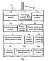
- FIG. 2is a block diagram illustrating one form of apparatus constructed in accordance with the present invention.
- FIG. 2 ais a sectional view of FIG. 2 along line a—a;
- FIG. 3is a three-dimensional view illustrating the sensor head in the apparatus of FIG. 2 ;
- FIG. 3 a and 3 bare sectional views of the sensor head in FIG. 3 , along the ZY-plane and XZ-plane, respectively,
- FIG. 4diagrammatically illustrates the configuration of the electric and magnetic fields produced by the sensor head of FIG. 3 ;
- FIG. 5is a block diagram illustrating the major components or modules in the apparatus of FIGS. 2–4 ;
- FIG. 6is a flow chart illustrating a preferred mode of operation of the apparatus of FIGS. 2–5 ;
- FIGS. 7 a – 7 dare waveforms helpful in understanding the operation of the apparatus of FIGS. 2–6 ;
- FIGS. 8 a – 8 millustrate a number of possible variations in the polarizing magnetic field and the transmission line ending in the apparatus of FIGS. 2–6 ;
- FIGS. 9 a – 9 fillustrate further possible variations in the configurations of the polarizing magnetic field and transmission line
- FIG. 10diagrammatically illustrates a leaky transmission line configuration of sensor head in accordance with the present invention
- FIG. 11illustrates the invention embodied in a catheter for insertion into the lumen of the patient's body
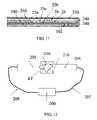
- FIG. 12illustrates apparatus constructed in accordance with the present invention including two sensor heads to be applied to opposite sides of the tissue being examined;
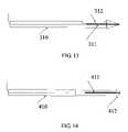
- FIG. 13diagrammatically illustrates a sensor head in accordance with the present invention incorporated in a biopsy needle
- FIG. 14illustrates a sensor head constructed in accordance with the present invention incorporated in a cutting tool so as to enable obtaining an indication of the tissue type in real time during a surgical operation.
- FIG. 1Basic Principle of Operation
- the basic way by which the present invention realizes the multi-modality approachis by combining EI sensing and NMR sensing into one integrated sensor head that collects signals corresponding to both phenomena substantially simultaneously (i.e., within a short, e.g., up to a few seconds) from the same tissue volume (the examined tissue volume).
- a calculation of the dielectric properties of the examined tissue volumecan be derived, as well as the nuclear magnetic resonance properties, known as NMR.
- the change in the dielectric properties of the examined tissue volume induced by the presence of the nuclear spin polarizing magnetic fieldis also measured, forming a third modality.
- Tissue characterization or recognitionis performed by using algorithms based on statistical analysis of the measured parameters, and by identifying similarities between the set of measured parameters and sets of pre-recorded parameters of known tissue types stored in the memory bank of the system.
- the principle of operationcan be briefly described by the following operations: application of a constant, or slowly varying polarizing magnetic field to a tissue volume; application of RF electromagnetic fields (while the polarizing magnetic field is applied) to the same tissue volume; and detection of both the EI response and MR (preferably NMR) signals from that tissue volume.
- the geometry (direction) of the generated polarizing magnetic fieldmust be such that it always has a component perpendicular (orthogonal) to the magnetic field associated with the RF radiation generated in the vicinity of the probe.
- the polarizing fieldalways has a component in the direction of the electric field associated with the RF radiation generated in the vicinity of the probe.
- FIG. 1is a schematic illustration of the presented geometry.
- the tissue volume examined ETis incident by the RF radiation pulse RF I generated by the source and transmitted by the transmission line (TL, FIG. 2 a ), with that radiation reflected back as a reflected pulse RF R .
- the E-field component E RF of the incident pulse RF Iis in the Z direction
- the B-field (magnetic) component B RF of the incident pulse RF Iis in the direction of the X-axis.
- the magnetic field associated with the RF radiation generated by RF I in the vicinity of the probeinduces a precession of the spins polarized by the external (polarizing) magnetic field Bp, thus generating an NMR Free Induction Decay (FID) signal FID when these spins' direction (the magnetization vector) relaxes back to the polarizing field's direction (the Z-direction in FIG. 1 ), following the RF pulse RF I .
- FIDNMR Free Induction Decay
- This NMR signalis further detected simultaneously with the RF reflection response RF R of the tissue examined.
- the NMR signalcould be detected as an absorption in the reflected spectrum of the RF signal RF R , followed by the FID signal, in the X-direction in FIG. 1 .
- the NMR signalcould also be detected by an additional magnetic transient field detector, which is perpendicular both to the polarizing magnetic field and the RF excitation related magnetic field so that it is sensitive to magnetic fields in the Y-direction in FIG. 1 .
- the RF signals RF I generated at the end of the transmission line TLcan be used according to two modes of operation:
- a first mode of operationthey can be used with pulse duration signals which are much shorter than the time scales related to NMR signals (the spin-lattice relaxation time T 1 , and the spin-spin relaxation time T 2 ), and which have a repetition rate much higher than the time scales related to NMR signals.
- the systemis viewed as a “continuous wave” NMR system, in the sense that the pumping is effectively continuous, even though the RF radiation, being extremely broadband, will have only a small bandwidth in resonance with the spins.
- the incident RF signals RF Ican be pulses of a length and duty cycle comparable to those used in NMR studies, in which case the system can be viewed as a pulsed NMR system.
- the relaxation signalsare then detected by the TL and/or an additional receiver. This second form of use is the one illustrated in FIG. 1 .
- the NMR signal generatedcould be of the numerous and assorted types of NMR signal known to those skilled in the art.
- the proton density weighted (PD), the T 1 weighted, and the T 2 weightedroutinely used in MRI as described for example in Nitz et al “Contrast Mechanisms in MR Imaging”, Eur Radiol, 9, 1032–1046 (1999).
- the polarizing magnetic fieldcan be modified, and turned on and off, thereby providing a means of measuring the dielectric response of the tissue with various types (including none) of its NMR response. By comparing these responses, the synergistic effect of the modalities is achieved, providing the additional, third modality.
- the ability to control the polarizing fieldcan also be used to improve dramatically the signal-to noise ratio S/N by using phase locking techniques, by applying a modulation to the polarizing field, for example at 120 Hz. As described more particularly below, this can be achieved, for example, by moving a set of permanent magnets along the Y-direction in FIG. 1 , or by changing the location or the driving current in coils, with and without a paramagnetic core. The measurement of the RF reflection is then “locked-on” to this reference frequency and phase.
- the TL probecan be of various shapes and types depending on how deep the RF radiation needs to penetrate into the examined tissue.
- Open cavity ending, open ended, or short ended TL types of endingcan be used for generating RF fields only in the near vicinity of the TL, whereupon the range of penetration would be in the order of the diameter of the TL (for coax) or the distance between the strip (for flat lines).
- Wideband antennaslike a conical antenna, can be used to radiate the energy into the body.
- the material of which the TL section attached to the permanent magnetsshould be magnetically transparent.
- the reflectiondepends on the impedance differences between the continuous section of the TL and its endings.
- the endingcould be of various types and shapes, its impedance will be correspondingly altered when placed in the close vicinity of the tissue, due to the dielectric properties of the tissue.
- the reflected pulsecarries with it information about the dielectric properties of the examined tissue. These properties produce a change in the time-domain-profile of the reflected pulse.
- the basic measurement conceptis well known and is referred to in the literature on the open-ended transmission line measurement method. A preferred construction is described in International Publication No. WO 03/060462 A2, published Jul. 24, 2003, assigned to the assignee of the present application, the contents of which are incorporated by reference.
- the electrical characteristics of the reflected electrical pulseare compared, both in time domain and frequency domain, with those of the applied (incident) electrical pulse by sampling both electrical pulses at a plurality of spaced time intervals, e.g., every 0.2 nanoseconds, and comparing the voltage magnitudes of the two electrical pulses at the spaced time intervals.
- the reflection coefficient and the time domain filtering properties of the examined tissueare then calculated.
- the frequency dependent complex impedance of the tissueis then calculated using the theoretical relation between impedance and reflection.
- the signalsare then modeled and reduced into a parameter set that describes and characterizes the tissue measured.
- the EI measurementcan also be conducted in the transmission mode.
- an electrical signalis launched via the transmission line of one probe through the examined tissue and collected by another similar open-ended probe placed on the other side of the tissue.
- This mode of operationhas an advantage from the signal-processing standpoint (although requiring two sided approach and two probes) since the affect of the electrical properties of the tissue on the transmitted signal is stronger then on the reflected signal. This provides a better S/N for the measurement of the tissue properties.
- This mode of operationis more particularly described below with respect to FIG. 12 .
- the effect of the polarizing magnetic field on the evoked (e.g., reflected) pulsesis through the additional absorption of energy from the incident pulse, by the nuclear magnetization vector created due to the presence of the polarizing field. This energy is used to create the precession of the magnetization vector around the direction of the polarizing field. This additional absorption affects the way the electric field is built inside the tissue volume and therefore changes its RF impedance EI. This absorption will appear as a change in the spectrum of the evoked pulse.
- FIGS. 2–7A Preferred Construction
- FIG. 2illustrated one form of apparatus, therein generally designated 2 , constructed in accordance with the present invention for examining tissue, indicated at ET, to characterize its type, particularly to distinguish cancerous tissue from non-cancerous tissue.
- the apparatus illustrated in FIG. 2includes a multi-modality probe 10 having a sensor head 20 to be placed into contact with the tissue ET to be examined for applying RF pulses via a transmission line TL, and sensor head 20 at the distal end of the transmission line, to the examined tissue.
- the applied RF pulsesare such as to invoke electrical impedance (ED) response signals corresponding to the electrical impedance properties of the examined tissue, and nuclear magnetic resonance (NMR) response signals corresponding to the NMR properties of the examined tissue.
- Probe 10is incorporated in a housing which is conveniently graspable by the user for manipulating the sensor head 20 .
- the detected signalsare fed to a remotely-located processing unit 50 communicating with the probe unit 10 via a flexible cable set 42 , containing the transmission line, additional signal cables and control line cables. Additional signal and control lines 45 ( FIG. 2 a ) and utility lines 47 are also extended through the probe unit 10 up to the sensor head 20 .
- the probe sensing head 20 in this exampleis designed to detect both EI reflection signals RF R and NMR signals FID from the tissue ET. Sensing head 20 integrates both modalities and also allows the third synergetic mode to be used. Both types of signals are useful for the identification of various tissue types, such as (but not limited to) normal and cancerous tissue.
- the measurementsare preferably performed in real-time and continuously as the probe is scanned over a tissue section, but may also be performed on the user's demand.
- the connection between the probe sensing head 20 and the transmission line TLis made as continuous as possible so that the probe sensing head 20 constitutes the distal end of the transmission line TL.
- FIG. 3illustrates the construction of the probe sensing head 20 and identifies the various axes involved during the operation of the probe as described more particularly below.
- the proximal end of sensing head 20includes a connector 21 for connecting it to the transmission line TL so as to constitute the distal end of the transmission line.
- the distal end 22 of sensing head 20is adapted to be brought into contact with the tissue to be examined.
- a tuning circuit 23for varying the impedance of the open end of the transmission line defined by the sensing head 20 at the distal end of the transmission line TL.
- sensing head 20constitutes the open end of the transmission line TL. It serves as both a transmitter of the RF pulses applied to the examined tissue ET when contacting same, as well as a receiver of the response signals (reflected pulses in this case) from the examined tissue.
- the construction of the open end of sensing head 20is more particularly illustrated in the sectional views of FIG. 3 a (the ZY-plane) and FIG. 3 b (the XZ-plane).
- sensing head 20includes an outer housing 24 containing a transmission line section of the strip-line type, including three conductive strips 25 a , 25 b , 25 c , separated from each other by insulation 26 .
- the two outer conductive strips 25 a , 25 bconstitute the two ground plates of the strip-line, whereas the inner conductive strip 25 c constitutes the inner conductor of the strip-line.
- the ground plates 25 a , 25 bare made from a magnetically transparent conductive material, e.g., aluminum.
- the transmission line defined by sensing head 20is left open-ended and serves both as a transmitter and a receiver.
- the open endis connected by wires 23 a to the tuning circuit 23 .
- the impedance of the open ended transmission linecan be varied by tuning circuit 23 from zero up to about the open-end impedance.
- This tuningcan be used to increase/decrease the open-ended reflectivity, and to increase/decrease the strength of the B-RF field, that is, the magnetic field generated by the transmission of the RF pulse to the sensing head 20 at the distal end of the transmission line.
- the outer conductors 25 a , 25 b and the inner conductor 25 cdefine open cavities closed by the tissue ET being examined, such that when a pulse is transmitted through the transmission line, the pulse is reflected back to the transmission line.
- the reflectiondepends on the impedance of the region at the open cavity of the probe, which impedance depends on the dielectric properties of the examined tissue closing the open of the cavity. Accordingly, the reflected pulse carries with it information about the dielectric properties of the examined tissue. These properties produce a change in the time-domain-profile of the reflected pulse.
- the transmission line defined by conductors 25 a – 25 c of the sensing head 20also detect NMR signals evoked in response to the transmitted RF pulses.
- additional NMR signalsare detected by a pair of RF coils 27 , 28 , at the open end of the transmission line defined by conductors 25 a – 25 c , and are outputted from the sensing head 20 via conductors 27 a , 28 a , respectively extending through the sensing head.
- the sensing headfurther includes a small pre-amplifier 29 which serves, together with the tuning circuit 23 , in order to improve and to amplify the signals detected by the RF coils 27 , 28 .
- a pair of permanent magnets 31 , 32for generating a polarizing magnetic field Bp for aligning the spins of the nuclei in the examined tissue from which NMR signals will be generated.
- Magnets 31 , 32are designed to generate in region 30 a magnetic field Bp whose major component would be in the direction Z, perpendicular to the B-RF field generated in and near the open cavity.
- the B-RF fieldhas a different direction in the upper section of the sensor head, above the inner conductor 25 c , than in the lower section of the sensor head, below the inner conductor 25 c .
- These magnetswhich may be composed of (but not limited to) rare earth neubidium type magnetic material, may be attached to the outer conductors 25 a , 25 b with the ability to slide along them in the Y-direction within chambers 33 , 34 .
- the position of magnets 31 , 32can be controlled by air pressure inside the chambers 33 , 34 by an external air pump connected thereto via pipes 35 , 36 .
- the movement of magnets 31 , 32provides a means for modifying the strength/amplitude of magnetic field Bp in the region 30 , while not changing its direction significantly.
- the magnets' poles (N-S) directionis perpendicular to the probe's main axis (the Y axis). That is, the poles are aligned with the Z-axis.
- the transmission line section of the sensing head 20may be of different types, dimensions, impedances, materials, etc., as long as it kept magnetically transparent in the region where field Bp is generated by the magnets.
- the ending of the transmission line sectioncan be of various shapes and types depending on how deep the RF radiation is to penetrate into the examined tissue ET.
- the sensing headcan be ended as a wide band antenna, which could be of the type, for example, of a conical antenna in the case of a coax line, or a dipole antenna, or a V-shaped antenna, or a strip line antenna (the two ground strips being opened gradually to the sides) in the case the line is flat.
- the transmission linecan be also left open-ended, or can be ended by a surface coil or by a side emitting leaky end.
- the preferred wayis to form an open cavity at the end of the transmission line and let a small part of the tissue penetrate into the open cavity of the TL.
- the RF fieldscan be considered as with known geometrical configuration (the TL modes) inside the sensing head and near its end, and the RF fields will be transmitted only into a small proximal volume of the tissue, with little radiation transmitted into the remainder of the body.
- the additional receiving coils 27 , 28are positioned so that they will detect magnetic fields in a direction perpendicularly to both the Bp and the B-RF magnetic fields. Thus, they will be able to detect the NMR signal in the XZ plane, a direction in which the transmission line TL defined by the conductive strips 25 a – 25 c cannot detect the NMR signals.
- Their designcould be of the types known in the literature, such as: surface coils, single coils, multi-turn coils, saddle coils, etc.
- FIG. 4schematically illustrates the various fields present in the region 30 at the distal end of the transmission line defined by conductive strips 25 a – 25 c .
- the substantially homogenous polarizing magnetic field generated by the permanent magnets 31 , 32is shown as magnetic field Bp;
- the magnetic field generated by the transmission of the RF pulses from the distal end of the transmission lineis indicated by magnetic field B-RF which, as indicated earlier, extends in one direction between conductive strips 25 c and 25 a , and in the opposite direction between conductive strips 25 c and 25 b ;
- E-RFthe electric field generated by the transmission of the RF pulses from the distal end of the transmission line.
- the additional receiving coils 27 , 28when included, serve as additional receivers for detecting the NMR signal components along an axis orthogonal both to Bp (the polarizing magnetic field by the permanent magnets 31 , 32 ), and B-RF (the magnetic field generated by the transmission of the RF pulses from the distal end of the transmission line).
- Coils 27 , 28are orthogonal to the transmission line main axis (the Y-axis), so that the RF coils 27 , 28 detect NMR signals in the Y-direction.
- the signal fed into the probe sensing head 20 through the transmission line defined by conductive strips 25 a – 25 cis of the form of a train of repetitive pulses.
- the repetitive pulse traincalled the RF sequence, consists of combinations of repetitive pulses in which some are optimized for EI measurement, and some are optimized for NMR measurement.
- the NMR pulsescan be, for example, from one of the known (in the literature) NMR sequences.
- a combined sequence schematicallymay be as follows: First, an EI optimized set of pulses, e.g., a short nano-second pulse train followed by a time break, in which the reflection is collected with a very high sampling rate. This is followed by an NMR optimized set of pulses; for example, the NMR pulses can be the known inversion recovery, simple spin echo, Carr-Purcell-Meiboom-Gill echo train, stimulated echo, etc.
- FIG. 5is a block diagram illustrating one form of apparatus constructed and operating in accordance with the present invention as describes above; and FIG. 6 is a flow chart illustrating the operation of such an apparatus when used to examine tissue for distinguishing cancerous tissue from non-cancerous tissue.
- the block diagram illustrated in FIG. 5identifies the main components of the apparatus illustrated in FIG. 2 with corresponding reference numerals.
- FIG. 5illustrates the flexible cable set 42 (which contains the transmission line TL carried by probe 10 and having a distal end occupied by the sensor head 20 adapted to be brought into contact with the tissue to be examined) that connects the probe 10 to the processing unit 50 ( FIG. 2 ).
- FIG. 5also illustrates the controls, located within the processing unit 50 , for applying and receiving RF pulses via the transmission line TL and sensor head 20 to the examined tissue ET, which pulses are capable of invoking electrical impedance (EI) response signals corresponding to the electrical impedance of the examined tissue, and nuclei magnetic resonance (NMR) response signals corresponding to the NMR properties of the examined tissue.
- EIelectrical impedance
- NMRnuclei magnetic resonance
- control circuitry within processing unit 50also controls the sensor head 20 to detect the EI and NMR response signals, and to feed them via transmission line in flexible cable set 42 to the processing unit 50 for analyzing the detected response signals and for determining therefrom the type of tissue examined, e.g., cancerous or non-cancerous tissue. This determination is indicated to the user by an indicator in probe 10 . The determination may also be used to actuate a marker for marking the tissue according to the tissue-type determination.
- the controls within the processing unit 50include a signal generation module 51 capable of generating programmable electric pulses up to 5 GHz; a polarizing magnetic field control module 52 for controlling the polarizing magnetic field (Bp) within region 30 occupied by the examined tissue; and a user interface 53 .
- the user interface 53 modulecontrols the display unit, an audio unit, optionally a marking unit control, and a control panel. Some of the operation controls and indicators can be mounted on the probe handgrip unit.
- the main functions of the user interfaceare to control the operation of the system and to display (in visual and/or audio form) the outputs of the processing unit 50 in a way that will be informative to the user.
- the control of the polarizing magnetic fieldmay be effected by changing the position of the permanent magnets 31 , 32 ( FIG. 3 a ) of the sensor head 20 .
- One way to perform thisis by a mechanical push/pull shaft mechanically connected to the magnets and mechanically controlled by control module 52 .
- Another way of moving the magnetsis by the use of a vacuum assisted shaft.
- the magnetsare mechanically connected to a short shaft at their remote (relative to the distal end of the probe head) end.
- the short shaftis connected at its opposite side to an air piston.
- the air pistonis inserted into an air tube that is connected to a pulsed vacuum pump at the external unit side. Each time the air pressure is reduced in the tube, the magnets are pulled back and vice versa.
- the polarizing magnetic fieldwould be produced and controlled by electromagnets, in which case the change in the polarizing magnetic field would be effected by a change in the location of, or the current through the coils generating this polarizing field.
- Another alternativewould have the coils surrounding a paramagnetic core, in which case the change in the polarizing magnetic field would be effected by a change in the induced magnetic field in the core due to a change of current in the surrounding coils.
- the control and indicator circuitry within the processing unit 50would further include a signal collection and digitizing module 54 for detecting the excitation RF pulses the reflected RF pulses and the NMR pulses.
- a preferred way of detectionis by digitizing voltages along the transmission lines using an analog to digital converter module.
- the digitizer sampling rateis controlled so as to be able to reach up to twice the signal generator maximal frequency.
- the signal collection and digitizing module 54communicates with a signal analysis module 55 .
- the signal analysis moduleis a computer program made up of a set of software routines. It receives as an input the measured signals in the form of a set of vectors, and removes noises and artificial effects from the signals. Its output is the set of “clean” processed signals.
- the processing unitfurther includes a signal modeling module 56 , a classification module 57 , and a data-base module 59 .
- the signal-modeling module 56is a computer program, made up of a set of software routines, which calculates a set of parameters that characterize the measured tissue.
- the data-base module 59stores a database of various types of tissues and their characterizing set of parameters, including their statistical dispersion properties.
- the classification module 57is a computer program, made up of a set of software routines, which looks for similarities between the measured set of parameters outputted from the modeling module 56 , and the pre-recorded set found in the data-base module 59 .
- One simple similarity estimatoris the distance of the measured points, in the multi-dimensional parameter data-space, from the location of each one of the prerecorded groups, defining specific tissue types. The most similar group (best-match) defines the type of the examined tissue ET.
- the determination of the classification module 57is outputted via flexible cable set 42 to a tissue characterization indicator 40 within the hand-held probe 10 , which displays to the user the determined tissue type.
- the processing unit 50may also include a probe location module 58 , and a physical marking module 58 a controlled by the classification module 57 in the processing unit 50 .
- Marking module 58 acontrols the operation of marking a measured spot on the tissue by an appropriate physical mark when instructed by the processing unit 50 . It uses a detectable material to physically mark the location of measurement. The detection of the marking can be immediate or delayed by the user. The simplest way to perform the marking is by the use of visually detectable substance, e.g., a three color biological marking ink, emitted from a jet nozzle mounted at the tip of the probe. After tissue recognition has been performed, a printing order is sent to the jet nozzle and the appropriate color dot is printed.
- visually detectable substancee.g., a three color biological marking ink
- detectable marking materialcan be, for example, a physical marker conjugated to antibodies, metal balls, IR paint, etc.
- the markercan also be a solid marker like a small metal pin, or a combination of solid balls painted with a distinguishing color. The solid balls are palpable and the color is visible.
- the markercan also be detectable by other known modalities, like X-ray or ultrasound.
- processing unit 50further includes a patient monitoring and history module 59 a , and an operating system, generally designated 59 b , namely the computer software that controls and coordinates all the operations of the hardware and software components of the apparatus.
- probe 10applies a repetitive train of RF pulses, called an RF sequence, through the transmission line, defined by the conductive strips 25 a – 25 c , which pulses invoke electrical impedance (EI) response signals corresponding to the electrical impedance properties of the examined tissue, and nuclear magnetic resonance (NMR) response signals corresponding to the NMR properties of the examined tissue.
- EIelectrical impedance
- NMRnuclear magnetic resonance
- the RF sequence of pulsesconsists of some pulses optimized for EI measurement and other pulses optimized for NMR measurement.
- the response signals evoked by the applied sequence of RF pulsesare detected by the sensor head 20 and processed by the processing unit 50 to determine the type of tissue examined.
- the systemfirst sets a polarizing magnetic field (block 60 ).
- the systemthen applies an EI optimized set of pulses to the examined tissue (block 61 ) and collects the invoked pulse responses (block 62 ), which in this case would be reflected pulses reflected from the open end of the transmission line TL.
- the systemalso applies an NMR optimized set of pulses (block 63 ) to the tissue, and collects therefrom the NMR responses (block 64 ).
- the detected response signalswould thus provide information as to two modalities of the examined tissue, namely its EI properties and its NMR properties.
- the polarizing magnetic field (Bp), produced by the permanent magnets 31 , 32is modified as described above (block 65 ), and the operations of blocks 60 – 64 are repeated to obtain the corresponding information when the examined tissue is subjected to the modified polarizing magnetic field.
- the signals collected in the above-described operationsare analyzed for predetermined parameters (block 66 ), and a parameter set is prepared for the examined tissue (block 67 ).
- the parameter set prepared for the respective examined tissueis then compared with stored parameter sets of known tissue types as described above, and a best-match determination is made to identify the type of the examined tissue (block 68 ).
- the detection processis comprised of the following four operations: (1) signal collection/acquisition; (2) signal analysis; (3) signal parameters' modeling; and (4) classification of measured parameter set to known tissue type parameter set, prerecorded and saved in the memory bank of the system.
- the collection of the signalsis made by fast digitizing, using multiple acquisition channels.
- the analysisis made by the application of signal processing routines that clean the signals from noise and artificial affects.
- the modelingis made by a compression process that characterizes a signal by a relatively short array of parameters, and mathematically transforms the parameters to an orthogonal set of parameters. For example, a 10000 point acquired signal can be characterizes by an array 10 of parameters.
- the modelingis done both in the frequency domain and in the time domain.
- the classificationis performed by a best-match comparison of the measured parameters to known tissue parameters stored in the memory together with their statistical dispersion parameters, and by identification of similarities between the just measured parameter set and a specific tissue type group of parameters.
- the just examined tissue typeis characterized, and that information is, for example, stored in the system data-base (block 69 a ), displayed to the operator (block 69 b ), used to actuate a marker to mark the tissue (block 69 c ), or used in any other way needed, according to the specific procedure performed.
- FIGS. 7 a – 7 dprovide schematic illustrations of the synergistic EI response and NMR response of the examined tissue following the irradiation by a single pulse generated by the main unit's signal generator.
- FIG. 7 ashows the form of the excitation pulse generated.
- itis a pulse of the length of a few tens of microseconds, which will invoke both an EI response and an NMR response.
- Itis a pulse of the so-called 90 degree pulse type, know in the NMR literature.
- FIG. 7 bshows the response of the tissue to the excitation pulse shown in FIG. 7 a detected by sensor head 20 in the TL.
- the responseis delayed by a time interval t 1 due to the length of the TL, and is composed of two types of signals.
- the first (temporal) part, in time interval t 2is the EI response of the tissue, which “follows” the form of the excitation pulse in FIG. 7 a , but distorts it because of the frequency-dependent dielectric properties of the tissue and the absorption by the nuclear magnetization vector.
- the second part in time interval t 3is the free induction decay (FID) of the NMR signal generated by the relaxation of the nuclear spin magnetization vector in the examined tissue (region 30 , FIG.
- FIDfree induction decay
- FIG. 7 cshows a close up view of the signal in time interval t 1 and t 2 .
- the reflected EI pulseis similar to the incident pulse, but is distorted because of the tissue impedance and NMR absorption.
- FIG. 7 dis shown the response of the tissue to the excitation pulse shown in FIG. 7 a , detected by the RF coils 27 , 28 .
- the responseis composed only of the FID of the NMR signal generated due to the relaxation of the nuclear spin magnetization vector in the examined tissue in region 30 back to the direction of the Bp field (see FIG. 4 ) following the excitation by the excitation pulse in FIG. 7 a .
- the directions of detection (with regards to the NMR signal) of the coilsis orthogonal to that of the transmission line TL, the FID response is phase-shifted by 90 degrees relative to the FID signal detected by the transmission line TL (see FIG. 7 b ).
- the transmitted radiation's spectrumis determined by the form of the pulse, and by the design of the sensor.
- the spatial form of the radiation(lobe structure, etc.) is determined by the geometry of the sensor head 20 at the distal end of the transmission line TL. Since the examined tissue is in close proximity to the distal end of the transmission line, pulses reflected back into the transmission line because of the impedance differences between the tissue and distal end of the transmission line, provide direct information regarding the dielectric properties/response of the tissue. These are the signals in time interval t 2 in FIGS. 7 b – 7 d .
- the pulse form, duration, repetition, and sequence structureare designed, and are also controlled in real time, so that they will provide the maximal (S/N) resolution for differentiating between different types of tissue.
- the tissue measurementis based on a comparison of the incident pulse to the reflected pulse, and on the analysis of the FID, and results in a series of parameters characterizing the tissue; whereas the detection of cancerous tissue sections is based on the comparison of the, just measured, tissue parameters with the parameters defining various tissue types stored in the memory bank.
- the external polarizing magnetic field (Bp) generated by the magnets 31 , 32aligns the spins, and particularly nuclear spins of the nuclei (preferably proton/hydrogen) parallel to the aligning magnetic field lines. This generates a “nuclear magnetization vector” in the tissue volume 30 .
- the geometric orientation of the transmission-line transmitted RF pulsesis such (see also FIG. 4 ) that these RF pulses serve as an RF “deflecting” magnetic field for the “nuclear magnetization vector”, as is performed in numerous NMR procedures and set-ups.
- the NMR FID following the relaxation of the magnetization vector, which follows after the RF pulse has been transmitted,is detected by the sensor head 20 , providing detection of the NMR response of the tissue.
- the RF energy absorbed by the magnetization vector, as it is rotated during the RF pulse duration,is also detected, as a change in the spectrum of the dielectric response of the tissue examined.
- the RF receiving coils 27 , 28( FIG. 3 a ) detect the NMR FID signal components in the direction perpendicular to the transmission line TL receiving direction. This measurement provides additional information and a better signal-to-noise ratio, and is correlated with the NMR signals detected by the transmission line. This will improve the NMR signal detection abilities and sensitivity of the probe.
- the NMR response of the tissueis detected in three different ways by the system: 1) as an absorbance in the reflected RF pulse contributing to the effective calculated impedance; 2) as an FID following the RF reflected pulse; and 3) as an FID detected by the RF coils 27 , 28 .
- the significant NMR measured tissue parametersare, but not limited to proton density (PD), longitudinal relaxation time (T 1 ) and/or transverse relaxation time (T 2 ).
- the magnetic fields generated by the magnets 31 , 32may have a gradient in the Y direction (the direction along the probe axis). This will shorten the duration of the NMR response and weaken the signal due to NMR line broadening.
- the pulse sequenceis designed to take these issues into account.
- the magnetscould be arranged in a form that will minimize the gradient in the Y-direction (the direction along the probe axis) of the field generated by the magnets.
- the pulse sequencewould then be designed differently from the case when there is a significant gradient in the field, in order to obtain the best SNR for the NMR signal.
- the magnets 31 , 32 generating the Bpmay also be moved during the measurement process.
- the movementis in the Y direction (the direction parallel to the probe axis). This movement will generate changes in the amplitude, and may also generate slight changes in the direction/orientation of Bp.
- the amplitude of Bpcan be controlled by using coils and/or paramagnetic cores driven by coils. The effects would be the same as when physically moving permanent magnets.
- This movementwill serve a number of purposes: First, it will enhance detection sensitivity by the use of lock-in techniques. Secondly, since the external magnetic field is non-homogeneous, movement of the magnets translates to a change in the NMR resonance frequency (for a given spin) at a given distance from the probe tip. By controlling the resonance frequency and, separately, the form, duration, and rate of repetition of the RF pulses, additional information is obtainable regarding the NMR response of the tissue at a given distance from the probe tip. This will provide better characterization of the tissue's NMR response.
- the movement of the magnetscan also be used to provide information regarding the depth at which a change in the type of tissue occurs.
- the magnetsare moved so that the field Bp strength at a given distance from the probe tip will be set to a chosen value.
- the RF pulseswill be generated so as to enhance the NMR response from distances greater than the chosen distance from the probe tip. The differences in response of different types of tissue, at that chosen distance from the probe tip, can thus be used to locate the change in the type of tissue.
- FIGS. 8–14illustrate a number of possible variations that may be made in the above-described apparatus.
- FIG. 8 aillustrates a variation wherein the inner conductive strip 25 c , defining the inner conducting trace is extended up to the distal end of the probe head, making it flush with the outer conductive strips 25 a , 25 b defining the ground plates.
- the ends of the magnets 31 , 32could be flush with, or protruding, relative to the inner conducting trace 25 c and ground plates 25 a , 25 b .
- the RF coils 27 , 28are then also moved to the probe distal end. The substance volume sampled is situated directly in contact with the probe end.
- FIG. 8 billustrates a variation wherein the magnets are replaced by coils 75 surrounding paramagnetic cores 76 , generating the polarizing field when current is driven through the coils.
- the change in the amplitude of the polarizing fieldis performed by changing the intensity of the current through the coils. This current change induces a change in the magnetic field of the paramagnetic cores.
- the magnetscould be replaced by coils, which will generate the polarizing field when current is driven through them.
- the change in the amplitude of the polarizing fieldis performed by changing the intensity of the current transferred through the coils.
- FIG. 8 cillustrates a variation wherein the poles of the magnets 31 , 32 are oriented in a direction parallel to the main axis of the probe head (the Y-direction, as defined for the preferred embodiment).
- FIG. 8 dillustrates a variation wherein the polarizing magnetic field is generated by a “horse-shoe” shaped paramagnetic core 77 , driven by a surrounding coil 78 .
- FIG. 8 eillustrates a further variation wherein a current sensor, in the form, for example, of a pick-up coil 79 , is placed near the distal end of the probe head to measure the current that passes through the examined substance.
- a current sensorin the form, for example, of a pick-up coil 79 , is placed near the distal end of the probe head to measure the current that passes through the examined substance.
- FIGS. 8 f – 8 kare side and plan views illustrating further variations in the transmission line end structure: FIGS. 8 f , 8 g illustrate one ended by a dipole antenna 81 . FIGS. 8 h , 8 i illustrate one ended by a V-shaped antenna 82 ; and FIGS. 8 j , 8 k illustrate one ended by a surface coil 83 .
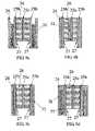
- FIGS. 8 l , 8 mare side and enlarged views, respectively, illustrating yet another embodiment including an array of miniature sensors all sharing the same source of polarizing magnetic field 31 , but each using different sources of RF radiation.
- FIGS. 9 a – 9 dillustrate further embodiments of the invention wherein the transmission line TL is of the cylindrical co-axial line type, having an inner conducting core 25 c , surrounded by an insulator 26 , which in turn is surrounded by a conductive cladding 25 b .
- the polarizing magnetic fieldis generated by a movable concentric magnet 31 , either surrounding the transmission line TL ( FIG. 9 a ), or surrounded by the transmission line TL ( FIG. 9 b ).
- the magnetis replaced by coils 75 ( FIG. 9 c ), or by coils 78 surrounding a paramagnetic core 77 ( FIG. 9 d ).
- FIG. 9 eend view
- FIG. 9 fplane view
- the transmission line sectionis made of two conducting strips only, without an inner trace.
- One strip 25 bserves as the ground plane
- the other strip 25 cserves as the signal plane.
- FIG. 10illustrates another embodiment wherein the transmission line TL is open-sided and leaky.
- a section of the outer conductor 100 of the transmission line TLis cut off and forms a window 105 .
- the inner conductor 101continues up to the end of the transmission line TL.
- the inner conductoris electrically connected to an impedance tuning circuit 103 .
- a permanent magnet 102is placed below the transmission line.
- the polarizing field lines 104 of the permanent magnethave a component in the window zone perpendicular to the B-RF field 106 which in FIG. 10 extends outwardly from the page plane.
- the measurementis performed by advancing the probe so that the sampled tissue is positioned in the window 105 .
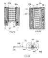
- FIG. 11illustrates yet another embodiment wherein the sensor head of the probe is placed on the distal end of a catheter and inserted into a lumen of the body for inspection of the lumen walls.
- the cut-off section of the outer conductor 250allows for analysis of tissue near the region 250 .
- the probeis covered by the catheter cladding 240 .
- FIG. 12illustrates another embodiment wherein two probes are used in a transmitter/receiver configuration.
- one probe 204acts in its turn as the transmitter, transmitting signals through the examined tissue ET, and the other probe 205 receives those signals and then in its turn act as a transmitter, while the first one acts as a receiver.
- both the reflected and transmitted signalsare detected.
- the transmitted signalsare fed through one transmission line 207 , and the detected signals are transferred through another transmission line 208 .
- Both transmission linesconnect to the main unit 200 .
- Magnets 210are positioned so that they will generate the necessary polarizing field.
- FIG. 13illustrates another embodiment wherein the sensor head of the probe 311 is placed inside a biopsy core needle 310 .
- the probecontinuously inspects the tissue type at the tip of the needle, as the needle is passing, from the outer skin surface to the biopsy site. Suspected tissue will be excised, for example, using a tissue-collecting cavity 312 .
- FIGS. 14illustrates yet another embodiment wherein the sensor head of the probe 411 is conjugated to a cutting tool, comprised of a handle 410 and a cutting head 412 , so that tissue recognition may be made prior to each excision cut.
- contrasting agentsfor example: gadodiamide or mangafodipir
- for the enhancement of the NMR signal for the characterization of various tissue parametersmay also be applied to the examined tissue, either locally, or intravenously.
- the RF sequence fed into the sensor through the transmission linemay consist of combinations of repetitive pulses, some optimized for the EI measurement and some optimized for EPR (electron paramagnetic resonance) measurements.
- the polarizing magnetic fieldmay also be optimized for the detection of EPR signals.
- Contrasting agentsfor example: activated charcoal, or cabamoyl-proxyl, or trityl-methyl based OX 031, OX036, to the enhance the EPR signal for better characterization of various tissue parameters, may also be applied to the examined tissue, either locally or intravenously.
- the RF sequence fed into the sensor through the transmission linemay also consist of combinations of repetitive pulses in which some are optimized for the EI measurement, and some are optimized for Proton Electron Double Resonance (PEDR), also known as Overhauser MR, measurements.
- PEDRProton Electron Double Resonance
- the polarizing magnetic fieldis also optimized for the detection of PEDR signals. Contrasting agents to enhance the Overhauser signal for the better characterization of various tissue parameters, may also be applied to the examined tissue, either locally, or intravenously.
- the inventioncould also be used for identifying other types of substances, for example, in situ characterization of composition of bore-hole walls, and in situ characterization of polymer and elastomer products and coatings.
Landscapes
- Health & Medical Sciences (AREA)
- Physics & Mathematics (AREA)
- Life Sciences & Earth Sciences (AREA)
- Nuclear Medicine, Radiotherapy & Molecular Imaging (AREA)
- General Health & Medical Sciences (AREA)
- Surgery (AREA)
- Veterinary Medicine (AREA)
- Engineering & Computer Science (AREA)
- Biomedical Technology (AREA)
- Heart & Thoracic Surgery (AREA)
- Medical Informatics (AREA)
- Molecular Biology (AREA)
- Biophysics (AREA)
- Animal Behavior & Ethology (AREA)
- Radiology & Medical Imaging (AREA)
- Public Health (AREA)
- Pathology (AREA)
- Condensed Matter Physics & Semiconductors (AREA)
- General Physics & Mathematics (AREA)
- High Energy & Nuclear Physics (AREA)
- General Life Sciences & Earth Sciences (AREA)
- Vascular Medicine (AREA)
- Magnetic Resonance Imaging Apparatus (AREA)
- Investigating Or Analyzing Materials By The Use Of Magnetic Means (AREA)
- Measurement Of The Respiration, Hearing Ability, Form, And Blood Characteristics Of Living Organisms (AREA)
- Investigating Or Analysing Biological Materials (AREA)
Abstract
Description
- 1. EMR probes completely different tissue parameters/states than NMR probes, including metabolism rates, pH, NO concentration, free radicals, reactive oxygen species, and oxygenation state.
- 2. EMR is usually preformed in conjugation with contrasting agents. These are spin-trap molecules that stabilize the paramagnetic species.
- 3. The polarizing magnetic fields used in EMR are much lower than those used in NMR.
- 1. Surowiex, A. J. et al., 1988, Dielectric Properties of Breast Carcinoma and the Surrounding Tissues, IEEE Trans. Biomed. Eng. 35(4):257–262.
- 2. Heintz, J. & O. Minet, 1995 Dielectric Properties of Female Breast Tumors, In Ninth International Conference on Electrical Bio-Impedance, Heidelberg.
- 3. Liefn, D. et al., 1998 Clinical Study on Electrical Impedance Method Used Diagnosis of Breast Diasi. In Tenth International Conference on Electrical Bio-Impedance. Barcelona.
- 4. Morimoto, et al., Measurement of Electrical Bio-Impedance of Breast Tumors, Eu. Serg. Res. 2292:86–92, 1990.
- 5. Dexter, G. et al, “In-Vivo Measurement of Tumor Conductiveness With Magnetic Bioimpedance Method”, IEEE Trans Biomedical Engine”, Vol. 47 No. 10 October 2000.
- 6. Prthig, R., (1978), Dielectric and Electronic Properties of Biological Materials, John Wiley, New York.
- 7. Schanna, O. F. et al., (1978), Impedance Measurement in Biological Cell. John Wiley, New York.
- 8. H. P. Schwan, Mechanisms Responsible for Electrical Properties of Tissue and Cell Suspensions, Med. Prog. Tech. 19:163–165, 1993.
- 9. Fricke, H. The Theory of Electrolytic Polarization. Philosophical Magazine 1932; (97):310–318.
- 10. Cole K S (1972) Membranes, Ions (1978) and Impulses. University of California Press, Berkeley.
Claims (51)
Priority Applications (4)
| Application Number | Priority Date | Filing Date | Title |
|---|---|---|---|
| US10/891,750US7082325B2 (en) | 2003-07-24 | 2004-07-15 | Method and apparatus for examining a substance, particularly tissue, to characterize its type |
| US11/487,431US7809425B2 (en) | 2003-07-24 | 2006-07-17 | Method and apparatus for examining a substance, particularly tissue, to characterize its type |
| US11/797,167US8032211B2 (en) | 2002-01-04 | 2007-05-01 | Probes, systems, and methods for examining tissue according to the dielectric properties thereof |
| US11/797,166US20080287750A1 (en) | 2002-01-04 | 2007-05-01 | Ergonomic probes |
Applications Claiming Priority (2)
| Application Number | Priority Date | Filing Date | Title |
|---|---|---|---|
| US48113003P | 2003-07-24 | 2003-07-24 | |
| US10/891,750US7082325B2 (en) | 2003-07-24 | 2004-07-15 | Method and apparatus for examining a substance, particularly tissue, to characterize its type |
Related Parent Applications (1)
| Application Number | Title | Priority Date | Filing Date |
|---|---|---|---|
| US10/298,196Continuation-In-PartUS7505811B2 (en) | 2001-11-19 | 2002-11-18 | Method and apparatus for examining tissue for predefined target cells, particularly cancerous cells, and a probe useful in such method and apparatus |
Related Child Applications (1)
| Application Number | Title | Priority Date | Filing Date |
|---|---|---|---|
| US11/487,431Continuation-In-PartUS7809425B2 (en) | 2002-01-04 | 2006-07-17 | Method and apparatus for examining a substance, particularly tissue, to characterize its type |
Publications (2)
| Publication Number | Publication Date |
|---|---|
| US20050021019A1 US20050021019A1 (en) | 2005-01-27 |
| US7082325B2true US7082325B2 (en) | 2006-07-25 |
Family
ID=34102641
Family Applications (1)
| Application Number | Title | Priority Date | Filing Date |
|---|---|---|---|
| US10/891,750Expired - LifetimeUS7082325B2 (en) | 2002-01-04 | 2004-07-15 | Method and apparatus for examining a substance, particularly tissue, to characterize its type |
Country Status (6)
| Country | Link |
|---|---|
| US (1) | US7082325B2 (en) |
| EP (1) | EP1653852A4 (en) |
| JP (1) | JP4777886B2 (en) |
| CN (1) | CN100473336C (en) |
| CA (1) | CA2533161C (en) |
| WO (1) | WO2005009200A2 (en) |
Cited By (76)
| Publication number | Priority date | Publication date | Assignee | Title |
|---|---|---|---|---|
| US20060264738A1 (en)* | 2003-07-24 | 2006-11-23 | Dune Medical Devices Ltd. | Method and apparatus for examining a substance, particularly tissue, to characterize its type |
| US20070019199A1 (en)* | 2005-07-25 | 2007-01-25 | The Wisconsin Alumni Research Foundation | Methods, systems, and computer program products for optimization of probes for spectroscopic measurement in turbid media |
| US20070032739A1 (en)* | 2005-08-04 | 2007-02-08 | Dune Medical Devices Ltd. | Device for forming an effective sensor-to-tissue contact |
| US20070032747A1 (en)* | 2005-08-04 | 2007-02-08 | Dune Medical Devices Ltd. | Tissue-characterization probe with effective sensor-to-tissue contact |
| US20070106342A1 (en)* | 2005-11-08 | 2007-05-10 | Schumann Daniel H | Device and method for the treatment of pain with electrical energy |
| US20070159372A1 (en)* | 2005-12-07 | 2007-07-12 | Weng Ching S | Bio-impedance sensing device for homecare and eHealth |
| US20070179397A1 (en)* | 2002-01-04 | 2007-08-02 | Dune Medical Devices Ltd. | Probes, systems, and methods for examining tissue according to the dielectric properties thereof |
| US20070232932A1 (en)* | 2006-03-17 | 2007-10-04 | Duke University | Monte Carlo based model of fluorescence in turbid media and methods and systems for using same to determine intrinsic fluorescence of turbid media |
| US20070255169A1 (en)* | 2001-11-19 | 2007-11-01 | Dune Medical Devices Ltd. | Clean margin assessment tool |
| US20080021343A1 (en)* | 2002-01-04 | 2008-01-24 | Dune Medical Devices Ltd. | Probes, systems, and methods for examining tissue according to the dielectric properties thereof |
| US20080103383A1 (en)* | 2006-10-23 | 2008-05-01 | Andre Van Der Kouwe | Selective MR imaging of segmented anatomy |
| US20080109049A1 (en)* | 2006-11-08 | 2008-05-08 | Schumann Daniel H | Device & method for relieving pain |
| US20080154090A1 (en)* | 2005-01-04 | 2008-06-26 | Dune Medical Devices Ltd. | Endoscopic System for In-Vivo Procedures |
| US20080214953A1 (en)* | 2007-03-01 | 2008-09-04 | Dune Medical Devices Ltd. | Tissue-characterization system and method |
| US20080269593A1 (en)* | 2004-05-28 | 2008-10-30 | Weinstock Ronald J | Method of integrated proton beam and therapeutic magnetic resonance therapy |
| US20080270091A1 (en)* | 2007-02-23 | 2008-10-30 | Nirmala Ramanujam | Scaling method for fast monte carlo simulation of diffuse reflectance spectra from multi-layered turbid media and methods and systems for using same to determine optical properties of multi-layered turbid medium from measured diffuse reflectance |
| WO2007126827A3 (en)* | 2006-03-30 | 2008-12-18 | Univ Duke | Optical assay system for intraoperative assessment of tumor margins |
| US20090062637A1 (en)* | 2005-03-29 | 2009-03-05 | Dune Medical Devices Ltd. | Electromagnetic Sensors for Tissue Characterization |
| US20090102480A1 (en)* | 2006-04-24 | 2009-04-23 | Koninklijke Philips Electronics N. V. | Shimming of electric field for electric properties tomography |
| US20090149732A1 (en)* | 2007-12-08 | 2009-06-11 | Weinstock Ronald J | System for use of electrical resonant frequencies in analyzing and treating abnormality of human and animal tissues |
| US20090187109A1 (en)* | 2001-11-19 | 2009-07-23 | Dune Medical Devices Ltd. | Method and apparatus for examining tissue for predefined target cells, particularly cancerous cells, and a probe useful in such method and apparatus |
| US7720532B2 (en) | 2004-03-23 | 2010-05-18 | Dune Medical Ltd. | Clean margin assessment tool |
| US20100134273A1 (en)* | 2006-08-02 | 2010-06-03 | Koninklijke Philips Electronics N.V. | Radiofrequency safety of switchable segmented transmission lines |
| US7801585B1 (en)* | 2003-06-02 | 2010-09-21 | Newlife Sciences Llc | System for analyzing and treating abnormality of human and animal tissues |
| US20100324627A1 (en)* | 2008-07-28 | 2010-12-23 | Newlife Sciences, Llc | Method and apparatus for resistivity measurement, detection and treatment in living tissue |
| US7904145B2 (en) | 2004-03-23 | 2011-03-08 | Dune Medical Devices Ltd. | Clean margin assessment tool |
| US20110059016A1 (en)* | 2007-09-27 | 2011-03-10 | Nirmala Ramanujam | Optical assay system with a multi-probe imaging array |
| US20110105865A1 (en)* | 2008-04-24 | 2011-05-05 | Duke University | Diffuse reflectance spectroscopy device for quantifying tissue absorption and scattering |
| US20110112435A1 (en)* | 2007-09-28 | 2011-05-12 | Nirmala Ramanujam | Systems and methods for spectral analysis of a tissue mass using an instrument, an optical probe, and a monte carlo or a diffusion algorithm |
| US8068894B2 (en) | 2003-08-21 | 2011-11-29 | Ischem Corporation | Automated methods and systems for vascular plaque detection and analysis |
| EP2418599A2 (en) | 2006-12-12 | 2012-02-15 | Dune Medical Devices Ltd. | Graphical user interfaces (gui), methods and apparatus for data presentation |
| US20120112747A1 (en)* | 2010-11-09 | 2012-05-10 | Mark Alexiuk | MRI Safety System |
| US8369930B2 (en) | 2009-06-16 | 2013-02-05 | MRI Interventions, Inc. | MRI-guided devices and MRI-guided interventional systems that can track and generate dynamic visualizations of the devices in near real time |
| US8437833B2 (en) | 2008-10-07 | 2013-05-07 | Bard Access Systems, Inc. | Percutaneous magnetic gastrostomy |
| US8478382B2 (en) | 2008-02-11 | 2013-07-02 | C. R. Bard, Inc. | Systems and methods for positioning a catheter |
| US8512256B2 (en) | 2006-10-23 | 2013-08-20 | Bard Access Systems, Inc. | Method of locating the tip of a central venous catheter |
| US8774907B2 (en) | 2006-10-23 | 2014-07-08 | Bard Access Systems, Inc. | Method of locating the tip of a central venous catheter |
| US8781555B2 (en) | 2007-11-26 | 2014-07-15 | C. R. Bard, Inc. | System for placement of a catheter including a signal-generating stylet |
| US8784336B2 (en) | 2005-08-24 | 2014-07-22 | C. R. Bard, Inc. | Stylet apparatuses and methods of manufacture |
| US8801693B2 (en) | 2010-10-29 | 2014-08-12 | C. R. Bard, Inc. | Bioimpedance-assisted placement of a medical device |
| US8849382B2 (en) | 2007-11-26 | 2014-09-30 | C. R. Bard, Inc. | Apparatus and display methods relating to intravascular placement of a catheter |
| USD724745S1 (en) | 2011-08-09 | 2015-03-17 | C. R. Bard, Inc. | Cap for an ultrasound probe |
| US9008756B2 (en) | 2008-06-11 | 2015-04-14 | Dune Medical Devices Ltd. | Mapping system and method for mapping a target containing tissue |
| US9091637B2 (en) | 2009-12-04 | 2015-07-28 | Duke University | Smart fiber optic sensors systems and methods for quantitative optical spectroscopy |
| US9125578B2 (en) | 2009-06-12 | 2015-09-08 | Bard Access Systems, Inc. | Apparatus and method for catheter navigation and tip location |
| US9211107B2 (en) | 2011-11-07 | 2015-12-15 | C. R. Bard, Inc. | Ruggedized ultrasound hydrogel insert |
| US9259290B2 (en) | 2009-06-08 | 2016-02-16 | MRI Interventions, Inc. | MRI-guided surgical systems with proximity alerts |
| USD754357S1 (en) | 2011-08-09 | 2016-04-19 | C. R. Bard, Inc. | Ultrasound probe head |
| US9339206B2 (en) | 2009-06-12 | 2016-05-17 | Bard Access Systems, Inc. | Adaptor for endovascular electrocardiography |
| US9445734B2 (en) | 2009-06-12 | 2016-09-20 | Bard Access Systems, Inc. | Devices and methods for endovascular electrography |
| US9456766B2 (en) | 2007-11-26 | 2016-10-04 | C. R. Bard, Inc. | Apparatus for use with needle insertion guidance system |
| US9492097B2 (en) | 2007-11-26 | 2016-11-15 | C. R. Bard, Inc. | Needle length determination and calibration for insertion guidance system |
| US9521961B2 (en) | 2007-11-26 | 2016-12-20 | C. R. Bard, Inc. | Systems and methods for guiding a medical instrument |
| US9532724B2 (en) | 2009-06-12 | 2017-01-03 | Bard Access Systems, Inc. | Apparatus and method for catheter navigation using endovascular energy mapping |
| US9554716B2 (en) | 2007-11-26 | 2017-01-31 | C. R. Bard, Inc. | Insertion guidance system for needles and medical components |
| US9636031B2 (en) | 2007-11-26 | 2017-05-02 | C.R. Bard, Inc. | Stylets for use with apparatus for intravascular placement of a catheter |
| US9649048B2 (en) | 2007-11-26 | 2017-05-16 | C. R. Bard, Inc. | Systems and methods for breaching a sterile field for intravascular placement of a catheter |
| US9681823B2 (en) | 2007-11-26 | 2017-06-20 | C. R. Bard, Inc. | Integrated system for intravascular placement of a catheter |
| US9750425B2 (en) | 2004-03-23 | 2017-09-05 | Dune Medical Devices Ltd. | Graphical user interfaces (GUI), methods and apparatus for data presentation |
| US9839372B2 (en) | 2014-02-06 | 2017-12-12 | C. R. Bard, Inc. | Systems and methods for guidance and placement of an intravascular device |
| US9901714B2 (en) | 2008-08-22 | 2018-02-27 | C. R. Bard, Inc. | Catheter assembly including ECG sensor and magnetic assemblies |
| US10046139B2 (en) | 2010-08-20 | 2018-08-14 | C. R. Bard, Inc. | Reconfirmation of ECG-assisted catheter tip placement |
| US10349890B2 (en) | 2015-06-26 | 2019-07-16 | C. R. Bard, Inc. | Connector interface for ECG-based catheter positioning system |
| US10449330B2 (en) | 2007-11-26 | 2019-10-22 | C. R. Bard, Inc. | Magnetic element-equipped needle assemblies |
| US10524691B2 (en) | 2007-11-26 | 2020-01-07 | C. R. Bard, Inc. | Needle assembly including an aligned magnetic element |
| US10639008B2 (en) | 2009-10-08 | 2020-05-05 | C. R. Bard, Inc. | Support and cover structures for an ultrasound probe head |
| US10751509B2 (en) | 2007-11-26 | 2020-08-25 | C. R. Bard, Inc. | Iconic representations for guidance of an indwelling medical device |
| US10820885B2 (en) | 2012-06-15 | 2020-11-03 | C. R. Bard, Inc. | Apparatus and methods for detection of a removable cap on an ultrasound probe |
| US10952654B2 (en) | 2017-03-14 | 2021-03-23 | International Business Machines Corporation | PH sensitive surgical tool |
| US10973584B2 (en) | 2015-01-19 | 2021-04-13 | Bard Access Systems, Inc. | Device and method for vascular access |
| US10992079B2 (en) | 2018-10-16 | 2021-04-27 | Bard Access Systems, Inc. | Safety-equipped connection systems and methods thereof for establishing electrical connections |
| US11000207B2 (en) | 2016-01-29 | 2021-05-11 | C. R. Bard, Inc. | Multiple coil system for tracking a medical device |
| US11103213B2 (en) | 2009-10-08 | 2021-08-31 | C. R. Bard, Inc. | Spacers for use with an ultrasound probe |
| US11198000B2 (en) | 2019-06-12 | 2021-12-14 | Truerelief, Llc | Methods for delivering pulsed electric current to living tissue |
| US11547316B2 (en) | 2010-11-30 | 2023-01-10 | Truerelief, Llc | Apparatus and method for treatment of pain with body impedance analyzer |
| US11911605B2 (en) | 2021-03-05 | 2024-02-27 | Truerelief Llc | Method and apparatus for injury treatment |
Families Citing this family (36)
| Publication number | Priority date | Publication date | Assignee | Title |
|---|---|---|---|---|
| EP1653852A4 (en) | 2003-07-24 | 2010-06-09 | Dune Medical Devices Ltd | Method and apparatus for examining a substance,particularly tissue, to characterize its type |
| CN101166471B (en)* | 2005-04-25 | 2012-04-25 | 皇家飞利浦电子股份有限公司 | Ultrasound probe having an operational indicator assembly |
| US9307925B2 (en)* | 2005-06-16 | 2016-04-12 | Aaken Laboratories | Methods and systems for generating electrical property maps of biological structures |
| EP2035818A1 (en)* | 2006-06-15 | 2009-03-18 | Technion Research & Development Foundation LTD. | Probe and system for electron spin resonance imaging |
| KR100871446B1 (en)* | 2006-12-05 | 2008-12-03 | 한국전자통신연구원 | Analysis method of reflection waves using an effective impedance |
| WO2008069414A1 (en)* | 2006-12-05 | 2008-06-12 | Electronics And Telecommunications Research Institute | Method of analyzing reflection waves using effective impedance |
| WO2009138934A1 (en)* | 2008-05-15 | 2009-11-19 | Koninklijke Philips Electronics N.V. | Method and system for detecting a fluid distribution in an object of interest |
| DE102008064405A1 (en) | 2008-06-02 | 2009-12-10 | Rohde & Schwarz Gmbh & Co. Kg | Measuring device and method for determining tissue parameters |
| WO2009152634A1 (en)* | 2008-06-18 | 2009-12-23 | Carag Ag | Measuring apparatus and measuring method for measuring the tissue formation in vascular prostheses |
| US8206315B2 (en)* | 2008-09-30 | 2012-06-26 | Suros Surgical Systems, Inc. | Real-time pathology |
| US8766634B2 (en) | 2009-04-20 | 2014-07-01 | Technion Research & Development Foundation Limited | Method and device of estimating a dose of ionizing radiation |
| CN102573622B (en) | 2009-08-03 | 2016-01-27 | 沙丘医疗设备有限公司 | For the electromagnetic transducer measured experimenter |
| CN102770085B (en)* | 2009-08-03 | 2015-06-10 | 沙丘医疗设备有限公司 | Surgical tool |
| US8970217B1 (en) | 2010-04-14 | 2015-03-03 | Hypres, Inc. | System and method for noise reduction in magnetic resonance imaging |
| CN102253417B (en)* | 2011-04-23 | 2013-03-06 | 汕头市超声仪器研究所有限公司 | Security checking method based on handheld ultra low field magnetic resonance imaging (MRI) system |
| US10383584B2 (en) | 2012-03-23 | 2019-08-20 | Koninklijke Philips N.V. | Photonic needle system with measurement integration times depending on needle displacement speed |
| US9507004B2 (en)* | 2013-07-31 | 2016-11-29 | The Government Of The United States Of America, As Represented By The Secretary Of Commerce | Electron spin resonance spectrometer and method for using same |
| EP3154428A4 (en)* | 2014-06-12 | 2018-02-21 | Technion Research & Development Foundation Limited | Method and system for electron paramagnetic resonance |
| BR112017004353A2 (en) | 2014-09-05 | 2017-12-05 | Hyperfine Res Inc | ferromagnetic magnification for magnetic resonance imaging |
| JP2016063860A (en)* | 2014-09-22 | 2016-04-28 | スカラ株式会社 | Moisture meter |
| WO2016077417A1 (en)* | 2014-11-11 | 2016-05-19 | Hyperfine Research, Inc. | Low field magnetic resonance methods and apparatus |
| IL238034B (en)* | 2015-03-30 | 2018-05-31 | Shmri Haim Ltd | System and hand-held probe for non-invasive real time analysis of body tissue |
| US10281536B2 (en)* | 2015-12-21 | 2019-05-07 | Schlumberger Technology Corporation | System and method for hand-held magnetic resonance imaging |
| DE102015226168A1 (en)* | 2015-12-21 | 2017-06-22 | Robert Bosch Gmbh | Use of a measuring device for the examination of components of a human or animal body |
| CN107643489B (en)* | 2016-07-22 | 2024-01-09 | 苏州宝时得电动工具有限公司 | Electric energy storage device, electric tool and control method thereof |
| WO2018059744A1 (en)* | 2016-09-27 | 2018-04-05 | Siemens Aktiengesellschaft | Endoscope and method for operating an endoscope |
| US10539637B2 (en) | 2016-11-22 | 2020-01-21 | Hyperfine Research, Inc. | Portable magnetic resonance imaging methods and apparatus |
| US10627464B2 (en) | 2016-11-22 | 2020-04-21 | Hyperfine Research, Inc. | Low-field magnetic resonance imaging methods and apparatus |
| US10718842B2 (en) | 2016-11-22 | 2020-07-21 | Hyperfine Research, Inc. | Systems and methods for automated detection in magnetic resonance images |
| US10691460B2 (en)* | 2016-12-13 | 2020-06-23 | International Business Machines Corporation | Pointer associated branch line jumps for accelerated line jumps |
| CN107101678B (en)* | 2017-05-11 | 2023-06-27 | 中国地质大学(武汉) | A two-phase flow flow sensor based on conductivity probe and its application method |
| EP3499258A1 (en)* | 2017-12-13 | 2019-06-19 | BIOTRONIK SE & Co. KG | Device and method for determining a local property of a biological tissue by means of an nmr sensor |
| DE102018214459B3 (en) | 2018-08-27 | 2019-12-24 | Robert Bosch Gmbh | Hand-held measuring device for the analysis of body fluids |
| JP7163516B2 (en)* | 2020-01-15 | 2022-10-31 | 朝日インテック株式会社 | Measuring device, detecting device and measuring method |
| CN114720927B (en)* | 2021-03-31 | 2025-01-14 | 无锡鸣石峻致医疗科技有限公司 | A nuclear magnetic resonance measurement system suitable for non-invasive quantitative detection of organs |
| CN116269733B (en)* | 2023-03-20 | 2024-05-03 | 成都飞云科技有限公司 | Pulse ablation catheter, device and pulse ablation method |
Citations (11)
| Publication number | Priority date | Publication date | Assignee | Title |
|---|---|---|---|---|
| US4625171A (en)* | 1983-02-14 | 1986-11-25 | Hitachi, Ltd. | Imaging apparatus using nuclear magnetic resonance |
| US4689567A (en)* | 1984-06-01 | 1987-08-25 | Advanced Nmr Systems, Inc. | NMR Fourier imaging from multiple echoes |
| US4751464A (en)* | 1987-05-04 | 1988-06-14 | Advanced Nmr Systems, Inc. | Cavity resonator with improved magnetic field uniformity for high frequency operation and reduced dielectric heating in NMR imaging devices |
| US5442290A (en)* | 1992-08-04 | 1995-08-15 | The Regents Of The University Of California | MRI gradient drive current control using all digital controller |
| US5735278A (en)* | 1996-03-15 | 1998-04-07 | National Research Council Of Canada | Surgical procedure with magnetic resonance imaging |
| US5758646A (en)* | 1994-09-12 | 1998-06-02 | U.S. Philips Corporation | Magnetic resonance imaging method with pulse sequence optimization and device for such method |
| US20010051774A1 (en)* | 2000-02-28 | 2001-12-13 | Peter Littrup | Multidimensional bioelectrical tissue analyzer |
| US6397095B1 (en)* | 1999-03-01 | 2002-05-28 | The Trustees Of The University Of Pennsylvania | Magnetic resonance—electrical impedance tomography |
| US20030199753A1 (en)* | 2002-04-23 | 2003-10-23 | Ethicon Endo-Surgery | MRI compatible biopsy device with detachable probe |
| US6766185B2 (en)* | 2000-05-22 | 2004-07-20 | The Board Of Trustees Of The Leland Stanford Junior University | Transmission line techniques for MRI catheter coil miniaturization and tuning |
| WO2005009200A2 (en) | 2003-07-24 | 2005-02-03 | Dune Medical Devices Ltd. | Method and apparatus for examining a substance,particularly tissue, to characterize its type |
Family Cites Families (6)
| Publication number | Priority date | Publication date | Assignee | Title |
|---|---|---|---|---|
| EP0191828A4 (en)* | 1984-08-13 | 1989-02-23 | Howard Roy Berke | Solid state nmr probe. |
| JPH10216072A (en)* | 1997-02-12 | 1998-08-18 | Olympus Optical Co Ltd | Magnetic resonance observation device |
| GB2357149A (en)* | 1999-12-08 | 2001-06-13 | Topspin Medical | MRI using non-homogeneous static field |
| JP2004520865A (en)* | 2000-07-25 | 2004-07-15 | リタ メディカル システムズ インコーポレイテッド | Apparatus for tumor detection and treatment using localized impedance measurements |
| US8055329B2 (en)* | 2001-01-22 | 2011-11-08 | Spectrum Dynamics Llc | Ingestible device for radioimaging of the gastrointestinal tract |
| US6813515B2 (en)* | 2002-01-04 | 2004-11-02 | Dune Medical Devices Ltd. | Method and system for examining tissue according to the dielectric properties thereof |
- 2004
- 2004-07-15EPEP04744981Apatent/EP1653852A4/ennot_activeWithdrawn
- 2004-07-15CNCNB200480027097XApatent/CN100473336C/ennot_activeExpired - Fee Related
- 2004-07-15USUS10/891,750patent/US7082325B2/ennot_activeExpired - Lifetime
- 2004-07-15WOPCT/IL2004/000641patent/WO2005009200A2/enactiveApplication Filing
- 2004-07-15CACA2533161Apatent/CA2533161C/ennot_activeExpired - Fee Related
- 2004-07-15JPJP2006520980Apatent/JP4777886B2/ennot_activeExpired - Fee Related
Patent Citations (11)
| Publication number | Priority date | Publication date | Assignee | Title |
|---|---|---|---|---|
| US4625171A (en)* | 1983-02-14 | 1986-11-25 | Hitachi, Ltd. | Imaging apparatus using nuclear magnetic resonance |
| US4689567A (en)* | 1984-06-01 | 1987-08-25 | Advanced Nmr Systems, Inc. | NMR Fourier imaging from multiple echoes |
| US4751464A (en)* | 1987-05-04 | 1988-06-14 | Advanced Nmr Systems, Inc. | Cavity resonator with improved magnetic field uniformity for high frequency operation and reduced dielectric heating in NMR imaging devices |
| US5442290A (en)* | 1992-08-04 | 1995-08-15 | The Regents Of The University Of California | MRI gradient drive current control using all digital controller |
| US5758646A (en)* | 1994-09-12 | 1998-06-02 | U.S. Philips Corporation | Magnetic resonance imaging method with pulse sequence optimization and device for such method |
| US5735278A (en)* | 1996-03-15 | 1998-04-07 | National Research Council Of Canada | Surgical procedure with magnetic resonance imaging |
| US6397095B1 (en)* | 1999-03-01 | 2002-05-28 | The Trustees Of The University Of Pennsylvania | Magnetic resonance—electrical impedance tomography |
| US20010051774A1 (en)* | 2000-02-28 | 2001-12-13 | Peter Littrup | Multidimensional bioelectrical tissue analyzer |
| US6766185B2 (en)* | 2000-05-22 | 2004-07-20 | The Board Of Trustees Of The Leland Stanford Junior University | Transmission line techniques for MRI catheter coil miniaturization and tuning |
| US20030199753A1 (en)* | 2002-04-23 | 2003-10-23 | Ethicon Endo-Surgery | MRI compatible biopsy device with detachable probe |
| WO2005009200A2 (en) | 2003-07-24 | 2005-02-03 | Dune Medical Devices Ltd. | Method and apparatus for examining a substance,particularly tissue, to characterize its type |
Non-Patent Citations (3)
| Title |
|---|
| Schwan "Mechanism Responsible for Electrical Properties of Tissues and Cell Suspensions", Medical Process Through Technology, 19: 163-165, 1993. |
| Smith et al. "In Vivo Measurement of Tumor Conductiveness With the Magnetic Bioimpedance Method", IEEE Transactions on Biomedical Engineering, 47(10): 1403-1405, 2000. |
| Surowiec et al. "Dielectric Properties of Breast Carcinoma and the Surrounding Tissues", IEEE Transactions on Biomedical Engineering, 35(4): 257-263, 1988. |
Cited By (148)
| Publication number | Priority date | Publication date | Assignee | Title |
|---|---|---|---|---|
| US20070255169A1 (en)* | 2001-11-19 | 2007-11-01 | Dune Medical Devices Ltd. | Clean margin assessment tool |
| US20090187109A1 (en)* | 2001-11-19 | 2009-07-23 | Dune Medical Devices Ltd. | Method and apparatus for examining tissue for predefined target cells, particularly cancerous cells, and a probe useful in such method and apparatus |
| US9226979B2 (en) | 2001-11-19 | 2016-01-05 | Dune Medical Devices Ltd. | Method and apparatus for examining tissue for predefined target cells, particularly cancerous cells, and a probe useful in such method and apparatus |
| US8195282B2 (en) | 2001-11-19 | 2012-06-05 | Dune Medical Devices Ltd | Method and apparatus for examining tissue for predefined target cells, particularly cancerous cells, and a probe useful in such method and apparatus |
| US20070179397A1 (en)* | 2002-01-04 | 2007-08-02 | Dune Medical Devices Ltd. | Probes, systems, and methods for examining tissue according to the dielectric properties thereof |
| US8019411B2 (en) | 2002-01-04 | 2011-09-13 | Dune Medical Devices Ltd. | Probes, systems, and methods for examining tissue according to the dielectric properties thereof |
| US20080021343A1 (en)* | 2002-01-04 | 2008-01-24 | Dune Medical Devices Ltd. | Probes, systems, and methods for examining tissue according to the dielectric properties thereof |
| US8032211B2 (en) | 2002-01-04 | 2011-10-04 | Dune Medical Devices Ltd. | Probes, systems, and methods for examining tissue according to the dielectric properties thereof |
| US8326398B2 (en) | 2003-06-02 | 2012-12-04 | Newlife Sciences Llc | System for analyzing and treating abnormality of human and animal tissues |
| US9550068B2 (en) | 2003-06-02 | 2017-01-24 | Newlife Sciences, Llc | System for analyzing and treating abnormality of human and animal tissues |
| US7801585B1 (en)* | 2003-06-02 | 2010-09-21 | Newlife Sciences Llc | System for analyzing and treating abnormality of human and animal tissues |
| US10499848B2 (en) | 2003-06-02 | 2019-12-10 | Truerelief, Llc | System for analyzing and treating abnormality of human and animal tissues |
| US8064988B2 (en) | 2003-06-02 | 2011-11-22 | Newlife Sciences, Llc | System for analyzing and treating abnormality of human and animal tissues |
| US20060264738A1 (en)* | 2003-07-24 | 2006-11-23 | Dune Medical Devices Ltd. | Method and apparatus for examining a substance, particularly tissue, to characterize its type |
| US7809425B2 (en) | 2003-07-24 | 2010-10-05 | Dune Medical Devices Ltd. | Method and apparatus for examining a substance, particularly tissue, to characterize its type |
| US8068894B2 (en) | 2003-08-21 | 2011-11-29 | Ischem Corporation | Automated methods and systems for vascular plaque detection and analysis |
| US11179053B2 (en) | 2004-03-23 | 2021-11-23 | Dilon Medical Technologies Ltd. | Graphical user interfaces (GUI), methods and apparatus for data presentation |
| US7904145B2 (en) | 2004-03-23 | 2011-03-08 | Dune Medical Devices Ltd. | Clean margin assessment tool |
| US9750425B2 (en) | 2004-03-23 | 2017-09-05 | Dune Medical Devices Ltd. | Graphical user interfaces (GUI), methods and apparatus for data presentation |
| US7720532B2 (en) | 2004-03-23 | 2010-05-18 | Dune Medical Ltd. | Clean margin assessment tool |
| US20080269593A1 (en)* | 2004-05-28 | 2008-10-30 | Weinstock Ronald J | Method of integrated proton beam and therapeutic magnetic resonance therapy |
| US7640052B2 (en)* | 2004-05-28 | 2009-12-29 | Ippp, Llc | Method of integrated proton beam and therapeutic magnetic resonance therapy |
| US20080154090A1 (en)* | 2005-01-04 | 2008-06-26 | Dune Medical Devices Ltd. | Endoscopic System for In-Vivo Procedures |
| US20090062637A1 (en)* | 2005-03-29 | 2009-03-05 | Dune Medical Devices Ltd. | Electromagnetic Sensors for Tissue Characterization |
| US7899515B2 (en) | 2005-03-29 | 2011-03-01 | Dune Medical Devices Ltd. | Electromagnetic sensors for tissue characterization |
| US7835786B2 (en) | 2005-07-25 | 2010-11-16 | Wisconsin Alumni Research Foundation | Methods, systems, and computer program products for optimization of probes for spectroscopic measurement in turbid media |
| US20070019199A1 (en)* | 2005-07-25 | 2007-01-25 | The Wisconsin Alumni Research Foundation | Methods, systems, and computer program products for optimization of probes for spectroscopic measurement in turbid media |
| US8721565B2 (en) | 2005-08-04 | 2014-05-13 | Dune Medical Devices Ltd. | Device for forming an effective sensor-to-tissue contact |
| US9526460B2 (en) | 2005-08-04 | 2016-12-27 | Dune Medical Devices Ltd. | Tissue-characterization probe with effective sensor-to-tissue contact |
| US20070032739A1 (en)* | 2005-08-04 | 2007-02-08 | Dune Medical Devices Ltd. | Device for forming an effective sensor-to-tissue contact |
| US20070032747A1 (en)* | 2005-08-04 | 2007-02-08 | Dune Medical Devices Ltd. | Tissue-characterization probe with effective sensor-to-tissue contact |
| US8116845B2 (en) | 2005-08-04 | 2012-02-14 | Dune Medical Devices Ltd. | Tissue-characterization probe with effective sensor-to-tissue contact |
| US10004875B2 (en) | 2005-08-24 | 2018-06-26 | C. R. Bard, Inc. | Stylet apparatuses and methods of manufacture |
| US11207496B2 (en) | 2005-08-24 | 2021-12-28 | C. R. Bard, Inc. | Stylet apparatuses and methods of manufacture |
| US8784336B2 (en) | 2005-08-24 | 2014-07-22 | C. R. Bard, Inc. | Stylet apparatuses and methods of manufacture |
| US8108047B2 (en) | 2005-11-08 | 2012-01-31 | Newlife Sciences Llc | Device and method for the treatment of pain with electrical energy |
| US20070106342A1 (en)* | 2005-11-08 | 2007-05-10 | Schumann Daniel H | Device and method for the treatment of pain with electrical energy |
| US7353058B2 (en)* | 2005-12-07 | 2008-04-01 | Healthy Biotech Corp. Ltd. | Bio-impedance sensing device for homecare and eHealth |
| US20070159372A1 (en)* | 2005-12-07 | 2007-07-12 | Weng Ching S | Bio-impedance sensing device for homecare and eHealth |
| US20070232932A1 (en)* | 2006-03-17 | 2007-10-04 | Duke University | Monte Carlo based model of fluorescence in turbid media and methods and systems for using same to determine intrinsic fluorescence of turbid media |
| US7818154B2 (en) | 2006-03-17 | 2010-10-19 | Duke University | Monte Carlo based model of fluorescence in turbid media and methods and systems for using same to determine intrinsic fluorescence of turbid media |
| WO2007126827A3 (en)* | 2006-03-30 | 2008-12-18 | Univ Duke | Optical assay system for intraoperative assessment of tumor margins |
| US20090015826A1 (en)* | 2006-03-30 | 2009-01-15 | Duke University | Optical assay system for intraoperative assessment of tumor margins |
| US7751039B2 (en) | 2006-03-30 | 2010-07-06 | Duke University | Optical assay system for intraoperative assessment of tumor margins |
| US7952704B2 (en) | 2006-03-30 | 2011-05-31 | Duke University | Optical assay system for intraoperative assessment of tumor margins |
| US20100301229A1 (en)* | 2006-03-30 | 2010-12-02 | Nirmala Ramanujam | Optical assay system for intraoperative assessment of tumor margins |
| US7839147B2 (en)* | 2006-04-24 | 2010-11-23 | Koninklijke Philips Electronics N.V. | Shimming of electric field for electric properties tomography |
| US20090102480A1 (en)* | 2006-04-24 | 2009-04-23 | Koninklijke Philips Electronics N. V. | Shimming of electric field for electric properties tomography |
| US20100134273A1 (en)* | 2006-08-02 | 2010-06-03 | Koninklijke Philips Electronics N.V. | Radiofrequency safety of switchable segmented transmission lines |
| US8339256B2 (en)* | 2006-08-02 | 2012-12-25 | Koninklijke Philips Electronics N.V. | Radiofrequency safety of switchable segmented transmission lines |
| US9833169B2 (en) | 2006-10-23 | 2017-12-05 | Bard Access Systems, Inc. | Method of locating the tip of a central venous catheter |
| US9265443B2 (en) | 2006-10-23 | 2016-02-23 | Bard Access Systems, Inc. | Method of locating the tip of a central venous catheter |
| US8831703B2 (en)* | 2006-10-23 | 2014-09-09 | The General Hospital Corporation | Selective MR imaging of segmented anatomy |
| US8774907B2 (en) | 2006-10-23 | 2014-07-08 | Bard Access Systems, Inc. | Method of locating the tip of a central venous catheter |
| US8858455B2 (en) | 2006-10-23 | 2014-10-14 | Bard Access Systems, Inc. | Method of locating the tip of a central venous catheter |
| US9345422B2 (en) | 2006-10-23 | 2016-05-24 | Bard Acess Systems, Inc. | Method of locating the tip of a central venous catheter |
| US8512256B2 (en) | 2006-10-23 | 2013-08-20 | Bard Access Systems, Inc. | Method of locating the tip of a central venous catheter |
| US20080103383A1 (en)* | 2006-10-23 | 2008-05-01 | Andre Van Der Kouwe | Selective MR imaging of segmented anatomy |
| US20080109049A1 (en)* | 2006-11-08 | 2008-05-08 | Schumann Daniel H | Device & method for relieving pain |
| EP2418599A2 (en) | 2006-12-12 | 2012-02-15 | Dune Medical Devices Ltd. | Graphical user interfaces (gui), methods and apparatus for data presentation |
| US20080270091A1 (en)* | 2007-02-23 | 2008-10-30 | Nirmala Ramanujam | Scaling method for fast monte carlo simulation of diffuse reflectance spectra from multi-layered turbid media and methods and systems for using same to determine optical properties of multi-layered turbid medium from measured diffuse reflectance |
| US8147423B2 (en) | 2007-03-01 | 2012-04-03 | Dune Medical Devices, Ltd. | Tissue-characterization system and method |
| US20080214953A1 (en)* | 2007-03-01 | 2008-09-04 | Dune Medical Devices Ltd. | Tissue-characterization system and method |
| US20110059016A1 (en)* | 2007-09-27 | 2011-03-10 | Nirmala Ramanujam | Optical assay system with a multi-probe imaging array |
| US9820655B2 (en) | 2007-09-28 | 2017-11-21 | Duke University | Systems and methods for spectral analysis of a tissue mass using an instrument, an optical probe, and a Monte Carlo or a diffusion algorithm |
| US20110112435A1 (en)* | 2007-09-28 | 2011-05-12 | Nirmala Ramanujam | Systems and methods for spectral analysis of a tissue mass using an instrument, an optical probe, and a monte carlo or a diffusion algorithm |
| US11707205B2 (en) | 2007-11-26 | 2023-07-25 | C. R. Bard, Inc. | Integrated system for intravascular placement of a catheter |
| US9649048B2 (en) | 2007-11-26 | 2017-05-16 | C. R. Bard, Inc. | Systems and methods for breaching a sterile field for intravascular placement of a catheter |
| US10105121B2 (en) | 2007-11-26 | 2018-10-23 | C. R. Bard, Inc. | System for placement of a catheter including a signal-generating stylet |
| US10231753B2 (en) | 2007-11-26 | 2019-03-19 | C. R. Bard, Inc. | Insertion guidance system for needles and medical components |
| US10966630B2 (en) | 2007-11-26 | 2021-04-06 | C. R. Bard, Inc. | Integrated system for intravascular placement of a catheter |
| US9999371B2 (en) | 2007-11-26 | 2018-06-19 | C. R. Bard, Inc. | Integrated system for intravascular placement of a catheter |
| US10849695B2 (en) | 2007-11-26 | 2020-12-01 | C. R. Bard, Inc. | Systems and methods for breaching a sterile field for intravascular placement of a catheter |
| US8849382B2 (en) | 2007-11-26 | 2014-09-30 | C. R. Bard, Inc. | Apparatus and display methods relating to intravascular placement of a catheter |
| US10751509B2 (en) | 2007-11-26 | 2020-08-25 | C. R. Bard, Inc. | Iconic representations for guidance of an indwelling medical device |
| US11134915B2 (en) | 2007-11-26 | 2021-10-05 | C. R. Bard, Inc. | System for placement of a catheter including a signal-generating stylet |
| US10238418B2 (en) | 2007-11-26 | 2019-03-26 | C. R. Bard, Inc. | Apparatus for use with needle insertion guidance system |
| US8781555B2 (en) | 2007-11-26 | 2014-07-15 | C. R. Bard, Inc. | System for placement of a catheter including a signal-generating stylet |
| US10602958B2 (en) | 2007-11-26 | 2020-03-31 | C. R. Bard, Inc. | Systems and methods for guiding a medical instrument |
| US10524691B2 (en) | 2007-11-26 | 2020-01-07 | C. R. Bard, Inc. | Needle assembly including an aligned magnetic element |
| US11779240B2 (en) | 2007-11-26 | 2023-10-10 | C. R. Bard, Inc. | Systems and methods for breaching a sterile field for intravascular placement of a catheter |
| US9681823B2 (en) | 2007-11-26 | 2017-06-20 | C. R. Bard, Inc. | Integrated system for intravascular placement of a catheter |
| US11123099B2 (en) | 2007-11-26 | 2021-09-21 | C. R. Bard, Inc. | Apparatus for use with needle insertion guidance system |
| US10449330B2 (en) | 2007-11-26 | 2019-10-22 | C. R. Bard, Inc. | Magnetic element-equipped needle assemblies |
| US9456766B2 (en) | 2007-11-26 | 2016-10-04 | C. R. Bard, Inc. | Apparatus for use with needle insertion guidance system |
| US9492097B2 (en) | 2007-11-26 | 2016-11-15 | C. R. Bard, Inc. | Needle length determination and calibration for insertion guidance system |
| US9521961B2 (en) | 2007-11-26 | 2016-12-20 | C. R. Bard, Inc. | Systems and methods for guiding a medical instrument |
| US11529070B2 (en) | 2007-11-26 | 2022-12-20 | C. R. Bard, Inc. | System and methods for guiding a medical instrument |
| US9526440B2 (en) | 2007-11-26 | 2016-12-27 | C.R. Bard, Inc. | System for placement of a catheter including a signal-generating stylet |
| US10342575B2 (en) | 2007-11-26 | 2019-07-09 | C. R. Bard, Inc. | Apparatus for use with needle insertion guidance system |
| US9549685B2 (en) | 2007-11-26 | 2017-01-24 | C. R. Bard, Inc. | Apparatus and display methods relating to intravascular placement of a catheter |
| US10165962B2 (en) | 2007-11-26 | 2019-01-01 | C. R. Bard, Inc. | Integrated systems for intravascular placement of a catheter |
| US9554716B2 (en) | 2007-11-26 | 2017-01-31 | C. R. Bard, Inc. | Insertion guidance system for needles and medical components |
| US9636031B2 (en) | 2007-11-26 | 2017-05-02 | C.R. Bard, Inc. | Stylets for use with apparatus for intravascular placement of a catheter |
| US20090149732A1 (en)* | 2007-12-08 | 2009-06-11 | Weinstock Ronald J | System for use of electrical resonant frequencies in analyzing and treating abnormality of human and animal tissues |
| US8478382B2 (en) | 2008-02-11 | 2013-07-02 | C. R. Bard, Inc. | Systems and methods for positioning a catheter |
| US8971994B2 (en) | 2008-02-11 | 2015-03-03 | C. R. Bard, Inc. | Systems and methods for positioning a catheter |
| US20110105865A1 (en)* | 2008-04-24 | 2011-05-05 | Duke University | Diffuse reflectance spectroscopy device for quantifying tissue absorption and scattering |
| US9008756B2 (en) | 2008-06-11 | 2015-04-14 | Dune Medical Devices Ltd. | Mapping system and method for mapping a target containing tissue |
| US20100324627A1 (en)* | 2008-07-28 | 2010-12-23 | Newlife Sciences, Llc | Method and apparatus for resistivity measurement, detection and treatment in living tissue |
| US9901714B2 (en) | 2008-08-22 | 2018-02-27 | C. R. Bard, Inc. | Catheter assembly including ECG sensor and magnetic assemblies |
| US11027101B2 (en) | 2008-08-22 | 2021-06-08 | C. R. Bard, Inc. | Catheter assembly including ECG sensor and magnetic assemblies |
| US8437833B2 (en) | 2008-10-07 | 2013-05-07 | Bard Access Systems, Inc. | Percutaneous magnetic gastrostomy |
| US9907513B2 (en) | 2008-10-07 | 2018-03-06 | Bard Access Systems, Inc. | Percutaneous magnetic gastrostomy |
| US9439735B2 (en) | 2009-06-08 | 2016-09-13 | MRI Interventions, Inc. | MRI-guided interventional systems that can track and generate dynamic visualizations of flexible intrabody devices in near real time |
| US9259290B2 (en) | 2009-06-08 | 2016-02-16 | MRI Interventions, Inc. | MRI-guided surgical systems with proximity alerts |
| US9125578B2 (en) | 2009-06-12 | 2015-09-08 | Bard Access Systems, Inc. | Apparatus and method for catheter navigation and tip location |
| US10912488B2 (en) | 2009-06-12 | 2021-02-09 | Bard Access Systems, Inc. | Apparatus and method for catheter navigation and tip location |
| US10231643B2 (en) | 2009-06-12 | 2019-03-19 | Bard Access Systems, Inc. | Apparatus and method for catheter navigation and tip location |
| US10271762B2 (en) | 2009-06-12 | 2019-04-30 | Bard Access Systems, Inc. | Apparatus and method for catheter navigation using endovascular energy mapping |
| US9532724B2 (en) | 2009-06-12 | 2017-01-03 | Bard Access Systems, Inc. | Apparatus and method for catheter navigation using endovascular energy mapping |
| US9445734B2 (en) | 2009-06-12 | 2016-09-20 | Bard Access Systems, Inc. | Devices and methods for endovascular electrography |
| US11419517B2 (en) | 2009-06-12 | 2022-08-23 | Bard Access Systems, Inc. | Apparatus and method for catheter navigation using endovascular energy mapping |
| US9339206B2 (en) | 2009-06-12 | 2016-05-17 | Bard Access Systems, Inc. | Adaptor for endovascular electrocardiography |
| US8369930B2 (en) | 2009-06-16 | 2013-02-05 | MRI Interventions, Inc. | MRI-guided devices and MRI-guided interventional systems that can track and generate dynamic visualizations of the devices in near real time |
| US8396532B2 (en) | 2009-06-16 | 2013-03-12 | MRI Interventions, Inc. | MRI-guided devices and MRI-guided interventional systems that can track and generate dynamic visualizations of the devices in near real time |
| US8768433B2 (en) | 2009-06-16 | 2014-07-01 | MRI Interventions, Inc. | MRI-guided devices and MRI-guided interventional systems that can track and generate dynamic visualizations of the devices in near real time |
| US8825133B2 (en) | 2009-06-16 | 2014-09-02 | MRI Interventions, Inc. | MRI-guided catheters |
| US8886288B2 (en) | 2009-06-16 | 2014-11-11 | MRI Interventions, Inc. | MRI-guided devices and MRI-guided interventional systems that can track and generate dynamic visualizations of the devices in near real time |
| US10639008B2 (en) | 2009-10-08 | 2020-05-05 | C. R. Bard, Inc. | Support and cover structures for an ultrasound probe head |
| US11998386B2 (en) | 2009-10-08 | 2024-06-04 | C. R. Bard, Inc. | Support and cover structures for an ultrasound probe head |
| US11103213B2 (en) | 2009-10-08 | 2021-08-31 | C. R. Bard, Inc. | Spacers for use with an ultrasound probe |
| US9091637B2 (en) | 2009-12-04 | 2015-07-28 | Duke University | Smart fiber optic sensors systems and methods for quantitative optical spectroscopy |
| US10046139B2 (en) | 2010-08-20 | 2018-08-14 | C. R. Bard, Inc. | Reconfirmation of ECG-assisted catheter tip placement |
| US9415188B2 (en) | 2010-10-29 | 2016-08-16 | C. R. Bard, Inc. | Bioimpedance-assisted placement of a medical device |
| US8801693B2 (en) | 2010-10-29 | 2014-08-12 | C. R. Bard, Inc. | Bioimpedance-assisted placement of a medical device |
| US20120112747A1 (en)* | 2010-11-09 | 2012-05-10 | Mark Alexiuk | MRI Safety System |
| US8901928B2 (en)* | 2010-11-09 | 2014-12-02 | Imris Inc. | MRI safety system |
| US11547316B2 (en) | 2010-11-30 | 2023-01-10 | Truerelief, Llc | Apparatus and method for treatment of pain with body impedance analyzer |
| USD754357S1 (en) | 2011-08-09 | 2016-04-19 | C. R. Bard, Inc. | Ultrasound probe head |
| USD724745S1 (en) | 2011-08-09 | 2015-03-17 | C. R. Bard, Inc. | Cap for an ultrasound probe |
| US9211107B2 (en) | 2011-11-07 | 2015-12-15 | C. R. Bard, Inc. | Ruggedized ultrasound hydrogel insert |
| US10820885B2 (en) | 2012-06-15 | 2020-11-03 | C. R. Bard, Inc. | Apparatus and methods for detection of a removable cap on an ultrasound probe |
| US9839372B2 (en) | 2014-02-06 | 2017-12-12 | C. R. Bard, Inc. | Systems and methods for guidance and placement of an intravascular device |
| US10863920B2 (en) | 2014-02-06 | 2020-12-15 | C. R. Bard, Inc. | Systems and methods for guidance and placement of an intravascular device |
| US10973584B2 (en) | 2015-01-19 | 2021-04-13 | Bard Access Systems, Inc. | Device and method for vascular access |
| US11026630B2 (en) | 2015-06-26 | 2021-06-08 | C. R. Bard, Inc. | Connector interface for ECG-based catheter positioning system |
| US10349890B2 (en) | 2015-06-26 | 2019-07-16 | C. R. Bard, Inc. | Connector interface for ECG-based catheter positioning system |
| US11000207B2 (en) | 2016-01-29 | 2021-05-11 | C. R. Bard, Inc. | Multiple coil system for tracking a medical device |
| US10952654B2 (en) | 2017-03-14 | 2021-03-23 | International Business Machines Corporation | PH sensitive surgical tool |
| US11510598B2 (en) | 2017-03-14 | 2022-11-29 | International Business Machines Corporation | PH sensitive surgical tool |
| US11621518B2 (en) | 2018-10-16 | 2023-04-04 | Bard Access Systems, Inc. | Safety-equipped connection systems and methods thereof for establishing electrical connections |
| US10992079B2 (en) | 2018-10-16 | 2021-04-27 | Bard Access Systems, Inc. | Safety-equipped connection systems and methods thereof for establishing electrical connections |
| US11666758B2 (en) | 2019-06-12 | 2023-06-06 | Truerelief, Llc | Systems and method for delivering pulsed electric current to living tissue |
| US11197999B2 (en) | 2019-06-12 | 2021-12-14 | Truerelief, Llc | Systems and method for delivering pulsed electric current to living tissue |
| US11198000B2 (en) | 2019-06-12 | 2021-12-14 | Truerelief, Llc | Methods for delivering pulsed electric current to living tissue |
| US12390639B2 (en) | 2019-06-12 | 2025-08-19 | Truerelief, Llc | Systems and method for delivering pulsed electric current to living tissue |
| US11911605B2 (en) | 2021-03-05 | 2024-02-27 | Truerelief Llc | Method and apparatus for injury treatment |
Also Published As
| Publication number | Publication date |
|---|---|
| EP1653852A4 (en) | 2010-06-09 |
| CN100473336C (en) | 2009-04-01 |
| CA2533161A1 (en) | 2005-02-03 |
| WO2005009200A2 (en) | 2005-02-03 |
| JP2007507245A (en) | 2007-03-29 |
| US20050021019A1 (en) | 2005-01-27 |
| EP1653852A2 (en) | 2006-05-10 |
| JP4777886B2 (en) | 2011-09-21 |
| WO2005009200A3 (en) | 2005-08-04 |
| CA2533161C (en) | 2013-04-23 |
| CN1852678A (en) | 2006-10-25 |
Similar Documents
| Publication | Publication Date | Title |
|---|---|---|
| US7082325B2 (en) | Method and apparatus for examining a substance, particularly tissue, to characterize its type | |
| US7809425B2 (en) | Method and apparatus for examining a substance, particularly tissue, to characterize its type | |
| EP1460936B1 (en) | System for examining tissue according to the dielectric properties thereof | |
| US7778682B2 (en) | Biopsy and sampling needle antennas for magnetic resonance imaging-guided biopsies | |
| EP0898716B1 (en) | Method of magnetic resonance imaging and spectroscopic analysis and associated apparatus | |
| CA2222742C (en) | Method of internal magnetic resonance imaging and spectroscopic analysis and associated apparatus | |
| US10610122B2 (en) | Linear velocity imaging tomography | |
| JP5889186B2 (en) | Surgical tools | |
| US8865076B2 (en) | Methods for detection and characterization of abnormal tissue and cells using an electrical system | |
| US7283868B2 (en) | Apparatus for sensing human prostate tumor | |
| CN105025787A (en) | System for image guided procedure | |
| WO2005057467A2 (en) | Tissue characterization using an eddy-current probe | |
| US20150038872A1 (en) | Multiple-electrode electrical impedance sensing biopsy sampling device and method | |
| WO2009142918A2 (en) | Electrical impedance sensing biopsy sampling device and method | |
| EP2901954A1 (en) | System for field ablation prediction | |
| CA2482291A1 (en) | Biopsy and sampling needle antennas for magnetic resonance imaging-guided biopsies | |
| CN112790863B (en) | Surgical instrument positioning method, magnetic resonance imaging system and electronic device | |
| Wong | Optimization of micro antennas for interventional/intravascular MRI | |
| HK1069967B (en) | System for examining tissue according to the dielectric properties thereof |
Legal Events
| Date | Code | Title | Description |
|---|---|---|---|
| AS | Assignment | Owner name:DUNE MEDICAL DEVICES LTD., ISRAEL Free format text:ASSIGNMENT OF ASSIGNORS INTEREST;ASSIGNORS:HASHIMSHONY, DAN;COHEN, GIL;REEL/FRAME:015590/0855;SIGNING DATES FROM 20040711 TO 20040712 | |
| STCF | Information on status: patent grant | Free format text:PATENTED CASE | |
| FEPP | Fee payment procedure | Free format text:PAYOR NUMBER ASSIGNED (ORIGINAL EVENT CODE: ASPN); ENTITY STATUS OF PATENT OWNER: SMALL ENTITY | |
| FPAY | Fee payment | Year of fee payment:4 | |
| FPAY | Fee payment | Year of fee payment:8 | |
| AS | Assignment | Owner name:OXFORD FINANCE LLC, AS COLLATERAL AGENT AND AS LEN Free format text:SECURITY INTEREST;ASSIGNORS:DUNE MEDICAL DEVICES LTD.;DUNE MEDICAL DEVICES, INC.;REEL/FRAME:043647/0301 Effective date:20170530 | |
| MAFP | Maintenance fee payment | Free format text:PAYMENT OF MAINTENANCE FEE, 12TH YR, SMALL ENTITY (ORIGINAL EVENT CODE: M2553) Year of fee payment:12 | |
| AS | Assignment | Owner name:DUNE MEDICAL DEVICES LTD., ISRAEL Free format text:RELEASE BY SECURED PARTY;ASSIGNOR:OXFORD FINANCE LLC, AS COLLATERAL AGENT AND LENDER;REEL/FRAME:053376/0194 Effective date:20200430 Owner name:DUNE MEDICAL DEVICES, INC., PENNSYLVANIA Free format text:RELEASE BY SECURED PARTY;ASSIGNOR:OXFORD FINANCE LLC, AS COLLATERAL AGENT AND LENDER;REEL/FRAME:053376/0194 Effective date:20200430 | |
| AS | Assignment | Owner name:DUNE MEDICAL DEVICES LTD., VIRGINIA Free format text:ASSIGNMENT OF ASSIGNORS INTEREST;ASSIGNOR:DUNE MEDICAL DEVICES LTD.;REEL/FRAME:053376/0227 Effective date:20200401 |