US7082032B1 - Heat dissipation device with tilted fins - Google Patents
Heat dissipation device with tilted finsDownload PDFInfo
- Publication number
- US7082032B1 US7082032B1US10/648,532US64853203AUS7082032B1US 7082032 B1US7082032 B1US 7082032B1US 64853203 AUS64853203 AUS 64853203AUS 7082032 B1US7082032 B1US 7082032B1
- Authority
- US
- United States
- Prior art keywords
- fins
- card
- circuit board
- heat
- heat dissipation
- Prior art date
- Legal status (The legal status is an assumption and is not a legal conclusion. Google has not performed a legal analysis and makes no representation as to the accuracy of the status listed.)
- Expired - Lifetime, expires
Links
Images


Classifications
- H—ELECTRICITY
- H01—ELECTRIC ELEMENTS
- H01L—SEMICONDUCTOR DEVICES NOT COVERED BY CLASS H10
- H01L23/00—Details of semiconductor or other solid state devices
- H01L23/34—Arrangements for cooling, heating, ventilating or temperature compensation ; Temperature sensing arrangements
- H01L23/36—Selection of materials, or shaping, to facilitate cooling or heating, e.g. heatsinks
- H01L23/367—Cooling facilitated by shape of device
- G—PHYSICS
- G06—COMPUTING OR CALCULATING; COUNTING
- G06F—ELECTRIC DIGITAL DATA PROCESSING
- G06F1/00—Details not covered by groups G06F3/00 - G06F13/00 and G06F21/00
- G06F1/16—Constructional details or arrangements
- G06F1/18—Packaging or power distribution
- G06F1/183—Internal mounting support structures, e.g. for printed circuit boards, internal connecting means
- G06F1/185—Mounting of expansion boards
- G—PHYSICS
- G06—COMPUTING OR CALCULATING; COUNTING
- G06F—ELECTRIC DIGITAL DATA PROCESSING
- G06F1/00—Details not covered by groups G06F3/00 - G06F13/00 and G06F21/00
- G06F1/16—Constructional details or arrangements
- G06F1/20—Cooling means
- H—ELECTRICITY
- H01—ELECTRIC ELEMENTS
- H01L—SEMICONDUCTOR DEVICES NOT COVERED BY CLASS H10
- H01L2924/00—Indexing scheme for arrangements or methods for connecting or disconnecting semiconductor or solid-state bodies as covered by H01L24/00
- H01L2924/0001—Technical content checked by a classifier
- H01L2924/0002—Not covered by any one of groups H01L24/00, H01L24/00 and H01L2224/00
Definitions
- Embodiments of the present inventionrelate to the field of cooling electronic componentry. More particularly, embodiments of the present invention relate to heat dissipation devices.
- Heat dissipation devicesare used to cool components of electronic devices, such as microprocessors.
- Typical heat dissipation devicesalso referred to as heat sinks, include a base having a flat surface that can be mounted to the component being cooled. Attached to the other surface of the base are a number of fins. Heat from the component is transferred to the base, from the base to the fins, and then to the air. The fins provide increased surface area for the heat dissipation device that enhances dissipation of the heat from the base.
- a fancan direct air over the base element and across the surface area of the fins.
- DIMMSdual in-line memory modules
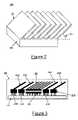
- FIG. 1illustrates placement of various computer components within housing 100 in accordance with the prior art.
- circuit board 105that is connected to a plurality of card connectors 110 a – 110 d .
- Card connectors 110 a – 110 dare connected to cards 115 a – 115 d , respectively, where cards 115 a – 115 d extend out from card connectors 110 a – 110 d at an angle.
- circuit board 105is connected to processor 120 .
- Mounted atop processor 120is heat sink 125 having a number of vertical fins 130 .
- FIG. 4illustrates a top view of exemplary placement of computer components within a housing in accordance with an embodiment of the present invention.
- Housing 400also optionally comprises air source 435 for increasing heat dissipation.
- air source 435is a fan situated at one side of tilted fin heat sink 425 , perpendicular to the fins of tilted fin heat sink 425 . Multiple fans can be used at either or both ends of tilted fin heat sink 425 . Other types of air sources can be used.
- Air source 435is operable to move air across tilted fin heat sink 425 , providing additional cooling.
- Arrows 440indicate the direction of air flow from air source 435 .
Landscapes
- Engineering & Computer Science (AREA)
- Theoretical Computer Science (AREA)
- General Physics & Mathematics (AREA)
- Physics & Mathematics (AREA)
- Computer Hardware Design (AREA)
- General Engineering & Computer Science (AREA)
- Human Computer Interaction (AREA)
- Power Engineering (AREA)
- Chemical & Material Sciences (AREA)
- Materials Engineering (AREA)
- Condensed Matter Physics & Semiconductors (AREA)
- Microelectronics & Electronic Packaging (AREA)
- Cooling Or The Like Of Electrical Apparatus (AREA)
Abstract
Description
Claims (7)
Priority Applications (1)
| Application Number | Priority Date | Filing Date | Title |
|---|---|---|---|
| US10/648,532US7082032B1 (en) | 2003-08-25 | 2003-08-25 | Heat dissipation device with tilted fins |
Applications Claiming Priority (1)
| Application Number | Priority Date | Filing Date | Title |
|---|---|---|---|
| US10/648,532US7082032B1 (en) | 2003-08-25 | 2003-08-25 | Heat dissipation device with tilted fins |
Publications (1)
| Publication Number | Publication Date |
|---|---|
| US7082032B1true US7082032B1 (en) | 2006-07-25 |
Family
ID=36687109
Family Applications (1)
| Application Number | Title | Priority Date | Filing Date |
|---|---|---|---|
| US10/648,532Expired - LifetimeUS7082032B1 (en) | 2003-08-25 | 2003-08-25 | Heat dissipation device with tilted fins |
Country Status (1)
| Country | Link |
|---|---|
| US (1) | US7082032B1 (en) |
Cited By (13)
| Publication number | Priority date | Publication date | Assignee | Title |
|---|---|---|---|---|
| US20050201063A1 (en)* | 2004-03-15 | 2005-09-15 | Hae-Hyung Lee | Semiconductor module with heat sink and method thereof |
| US20060187642A1 (en)* | 2005-02-22 | 2006-08-24 | Kwang-Jin Jeong | Structure for heat dissipation of integrated circuit chip and display module including the same |
| US20070068659A1 (en)* | 2005-09-23 | 2007-03-29 | Foxconn Technology Co., Ltd. | Thermal module |
| US20070285890A1 (en)* | 2006-06-13 | 2007-12-13 | Taiwan Semiconductor Manufacturing Co., Ltd. | Method and apparatus for increasing heat dissipation of high performance integrated circuits (ic) |
| US20100134980A1 (en)* | 2008-12-02 | 2010-06-03 | Yu Ming Han | Heat sink assembly |
| US20100134981A1 (en)* | 2008-12-03 | 2010-06-03 | Goodrich Corporation | Heat sink assembly having interdigitated cooling fins |
| DE102012007570A1 (en) | 2012-04-12 | 2013-10-17 | Technische Universität Ilmenau | Lamella-pipe heat exchanger for computer, has heat exchange tubes displaced in planes, and lamella arranged at another lamella at amount displaced in flow direction of medium, where spacing is reduced between lamellas |
| US20140321804A1 (en)* | 2013-04-26 | 2014-10-30 | Oracle International Corporation | Hybrid-integrated photonic chip package with an interposer |
| US20150139662A1 (en)* | 2012-06-12 | 2015-05-21 | FCI Asia Pte Ltd. | Heat Dissipation with an On-Board Connector |
| CN107251213A (en)* | 2015-02-20 | 2017-10-13 | 国际商业机器公司 | Use the supercomputer that wafer scale is integrated |
| US20180328624A1 (en)* | 2017-05-10 | 2018-11-15 | Dyson Technology Limited | Heater |
| US10378751B2 (en) | 2016-06-23 | 2019-08-13 | Osram Gmbh | Heat sink, corresponding lighting device and method of use |
| US11589661B2 (en) | 2017-01-12 | 2023-02-28 | Dyson Technology Limited | Hand held appliance |
Citations (7)
| Publication number | Priority date | Publication date | Assignee | Title |
|---|---|---|---|---|
| US4352008A (en)* | 1979-01-26 | 1982-09-28 | Firma Fritz Eichenauer | Electric heating device for heating the interior of a switch cabinet |
| US6301779B1 (en)* | 1998-10-29 | 2001-10-16 | Advanced Thermal Solutions, Inc. | Method for fabricating a heat sink having nested extended surfaces |
| US6525940B1 (en)* | 2001-12-04 | 2003-02-25 | Leadtek Research Inc. | Integrated apparatus for thermal dissipation |
| US6674644B2 (en)* | 2001-11-01 | 2004-01-06 | Sun Microsystems, Inc. | Module and connector having multiple contact rows |
| US20040032718A1 (en)* | 2002-08-14 | 2004-02-19 | Self Bob J. | Heatsink with improved heat dissipation capability |
| US6704199B2 (en)* | 2000-07-05 | 2004-03-09 | Network Engines, Inc. | Low profile equipment housing with angular fan |
| US6736204B2 (en)* | 2001-12-06 | 2004-05-18 | Sdk-Technik Gmbh | Heat transfer surface with a microstructure of projections galvanized onto it |
- 2003
- 2003-08-25USUS10/648,532patent/US7082032B1/ennot_activeExpired - Lifetime
Patent Citations (8)
| Publication number | Priority date | Publication date | Assignee | Title |
|---|---|---|---|---|
| US4352008A (en)* | 1979-01-26 | 1982-09-28 | Firma Fritz Eichenauer | Electric heating device for heating the interior of a switch cabinet |
| US6301779B1 (en)* | 1998-10-29 | 2001-10-16 | Advanced Thermal Solutions, Inc. | Method for fabricating a heat sink having nested extended surfaces |
| US6704199B2 (en)* | 2000-07-05 | 2004-03-09 | Network Engines, Inc. | Low profile equipment housing with angular fan |
| US6674644B2 (en)* | 2001-11-01 | 2004-01-06 | Sun Microsystems, Inc. | Module and connector having multiple contact rows |
| US6525940B1 (en)* | 2001-12-04 | 2003-02-25 | Leadtek Research Inc. | Integrated apparatus for thermal dissipation |
| US6736204B2 (en)* | 2001-12-06 | 2004-05-18 | Sdk-Technik Gmbh | Heat transfer surface with a microstructure of projections galvanized onto it |
| US20040032718A1 (en)* | 2002-08-14 | 2004-02-19 | Self Bob J. | Heatsink with improved heat dissipation capability |
| US6735082B2 (en)* | 2002-08-14 | 2004-05-11 | Agilent Technologies, Inc. | Heatsink with improved heat dissipation capability |
Cited By (24)
| Publication number | Priority date | Publication date | Assignee | Title |
|---|---|---|---|---|
| US20050201063A1 (en)* | 2004-03-15 | 2005-09-15 | Hae-Hyung Lee | Semiconductor module with heat sink and method thereof |
| US7345882B2 (en)* | 2004-03-15 | 2008-03-18 | Samsung Electronics Co., Ltd. | Semiconductor module with heat sink and method thereof |
| US20080144292A1 (en)* | 2004-03-15 | 2008-06-19 | Hae-Hyung Lee | Semiconductor module with heat sink and method thereof |
| US20060187642A1 (en)* | 2005-02-22 | 2006-08-24 | Kwang-Jin Jeong | Structure for heat dissipation of integrated circuit chip and display module including the same |
| US7365987B2 (en)* | 2005-02-22 | 2008-04-29 | Samsung Sdi Co., Ltd. | Structure for heat dissipation of integrated circuit chip and display module including the same |
| US20070068659A1 (en)* | 2005-09-23 | 2007-03-29 | Foxconn Technology Co., Ltd. | Thermal module |
| US20070285890A1 (en)* | 2006-06-13 | 2007-12-13 | Taiwan Semiconductor Manufacturing Co., Ltd. | Method and apparatus for increasing heat dissipation of high performance integrated circuits (ic) |
| US7583502B2 (en)* | 2006-06-13 | 2009-09-01 | Taiwan Semiconductor Manufacturing Co., Ltd. | Method and apparatus for increasing heat dissipation of high performance integrated circuits (IC) |
| US20100134980A1 (en)* | 2008-12-02 | 2010-06-03 | Yu Ming Han | Heat sink assembly |
| US7852631B2 (en)* | 2008-12-02 | 2010-12-14 | Asia Vital Components Co., Ltd. | Heat sink assembly |
| US20100134981A1 (en)* | 2008-12-03 | 2010-06-03 | Goodrich Corporation | Heat sink assembly having interdigitated cooling fins |
| US7907411B2 (en)* | 2008-12-03 | 2011-03-15 | Goodrich Corporation | Heat sink assembly having interdigitated cooling fins |
| DE102012007570A1 (en) | 2012-04-12 | 2013-10-17 | Technische Universität Ilmenau | Lamella-pipe heat exchanger for computer, has heat exchange tubes displaced in planes, and lamella arranged at another lamella at amount displaced in flow direction of medium, where spacing is reduced between lamellas |
| DE102012007570B4 (en) | 2012-04-12 | 2022-05-12 | Technische Universität Ilmenau | Fin tube heat exchanger with improved heat transfer |
| US20150139662A1 (en)* | 2012-06-12 | 2015-05-21 | FCI Asia Pte Ltd. | Heat Dissipation with an On-Board Connector |
| US20140321804A1 (en)* | 2013-04-26 | 2014-10-30 | Oracle International Corporation | Hybrid-integrated photonic chip package with an interposer |
| US9297971B2 (en)* | 2013-04-26 | 2016-03-29 | Oracle International Corporation | Hybrid-integrated photonic chip package with an interposer |
| CN107251213A (en)* | 2015-02-20 | 2017-10-13 | 国际商业机器公司 | Use the supercomputer that wafer scale is integrated |
| CN107251213B (en)* | 2015-02-20 | 2020-10-16 | 国际商业机器公司 | Supercomputers using wafer-level integration |
| US10378751B2 (en) | 2016-06-23 | 2019-08-13 | Osram Gmbh | Heat sink, corresponding lighting device and method of use |
| US11589661B2 (en) | 2017-01-12 | 2023-02-28 | Dyson Technology Limited | Hand held appliance |
| US11712098B2 (en) | 2017-01-12 | 2023-08-01 | Dyson Technology Limited | Hand held appliance |
| US20180328624A1 (en)* | 2017-05-10 | 2018-11-15 | Dyson Technology Limited | Heater |
| US11168924B2 (en)* | 2017-05-10 | 2021-11-09 | Dyson Technology Limited | Heater |
Similar Documents
| Publication | Publication Date | Title |
|---|---|---|
| US6421240B1 (en) | Cooling arrangement for high performance electronic components | |
| CN109727937B (en) | Assemblies including heat dissipating elements and related systems and methods | |
| US6687126B2 (en) | Cooling plate arrangement for electronic components | |
| US20060039117A1 (en) | Heat dissipation device | |
| US7369412B2 (en) | Heat dissipation device | |
| US7613001B1 (en) | Heat dissipation device with heat pipe | |
| US7522413B2 (en) | Heat dissipating system | |
| US20080043425A1 (en) | Methods and systems for cooling a computing device | |
| US20090147476A1 (en) | Circuit board apparatus with induced air flow for heat dissipation | |
| US7082032B1 (en) | Heat dissipation device with tilted fins | |
| US7339792B2 (en) | Graphics card apparatus with improved heat dissipating assemblies | |
| US20070201211A1 (en) | System for cooling a heat-generating electronic device with increased air flow | |
| US7321494B2 (en) | Graphics card apparatus with improved heat dissipating mechanisms | |
| CN111124081B (en) | Kits for enhanced cooling of components of computing devices and related systems and methods | |
| US11751357B2 (en) | Apparatus including thermal management mechanism and methods of manufacturing the same | |
| TW201314425A (en) | Radiator device and electronic device using same | |
| US5829515A (en) | Heat dissipator with multiple thermal cooling paths | |
| US20050094371A1 (en) | Electronic device and heat-dissipating module thereof | |
| US7626821B1 (en) | Adaptor for graphics module | |
| US6913069B2 (en) | Cooling device having fins arranged to funnel air | |
| US20080266806A1 (en) | Electronic assembly that includes a heat sink which cools multiple electronic components | |
| JP2014078688A (en) | Heat dissipation structure | |
| US20050254213A1 (en) | Air conditioning heat dissipation system | |
| CN108304048B (en) | Server and solid-state storage device thereof | |
| US11310941B2 (en) | Electronic device and heat sink |
Legal Events
| Date | Code | Title | Description |
|---|---|---|---|
| AS | Assignment | Owner name:HEWLETT-PACKARD DEVELOPMENT COMPANY, L.P., TEXAS Free format text:ASSIGNMENT OF ASSIGNORS INTEREST;ASSIGNORS:BARSUN, STEPHAN KARL;HENSLEY, JAMES D.;BARR, ANDREW HARVEY;REEL/FRAME:014020/0680 Effective date:20030821 | |
| STCF | Information on status: patent grant | Free format text:PATENTED CASE | |
| FPAY | Fee payment | Year of fee payment:4 | |
| FPAY | Fee payment | Year of fee payment:8 | |
| AS | Assignment | Owner name:HEWLETT PACKARD ENTERPRISE DEVELOPMENT LP, TEXAS Free format text:ASSIGNMENT OF ASSIGNORS INTEREST;ASSIGNOR:HEWLETT-PACKARD DEVELOPMENT COMPANY, L.P.;REEL/FRAME:037079/0001 Effective date:20151027 | |
| MAFP | Maintenance fee payment | Free format text:PAYMENT OF MAINTENANCE FEE, 12TH YEAR, LARGE ENTITY (ORIGINAL EVENT CODE: M1553) Year of fee payment:12 | |
| AS | Assignment | Owner name:OT PATENT ESCROW, LLC, ILLINOIS Free format text:PATENT ASSIGNMENT, SECURITY INTEREST, AND LIEN AGREEMENT;ASSIGNORS:HEWLETT PACKARD ENTERPRISE DEVELOPMENT LP;HEWLETT PACKARD ENTERPRISE COMPANY;REEL/FRAME:055269/0001 Effective date:20210115 | |
| AS | Assignment | Owner name:VALTRUS INNOVATIONS LIMITED, IRELAND Free format text:ASSIGNMENT OF ASSIGNORS INTEREST;ASSIGNOR:OT PATENT ESCROW, LLC;REEL/FRAME:061244/0298 Effective date:20220803 |