US7081734B1 - Ride-through method and system for HVACandR chillers - Google Patents
Ride-through method and system for HVACandR chillersDownload PDFInfo
- Publication number
- US7081734B1 US7081734B1US11/218,757US21875705AUS7081734B1US 7081734 B1US7081734 B1US 7081734B1US 21875705 AUS21875705 AUS 21875705AUS 7081734 B1US7081734 B1US 7081734B1
- Authority
- US
- United States
- Prior art keywords
- voltage
- stage
- link
- motor
- inverter
- Prior art date
- Legal status (The legal status is an assumption and is not a legal conclusion. Google has not performed a legal analysis and makes no representation as to the accuracy of the status listed.)
- Expired - Lifetime
Links
Images


Classifications
- H—ELECTRICITY
- H02—GENERATION; CONVERSION OR DISTRIBUTION OF ELECTRIC POWER
- H02M—APPARATUS FOR CONVERSION BETWEEN AC AND AC, BETWEEN AC AND DC, OR BETWEEN DC AND DC, AND FOR USE WITH MAINS OR SIMILAR POWER SUPPLY SYSTEMS; CONVERSION OF DC OR AC INPUT POWER INTO SURGE OUTPUT POWER; CONTROL OR REGULATION THEREOF
- H02M7/00—Conversion of AC power input into DC power output; Conversion of DC power input into AC power output
- H02M7/66—Conversion of AC power input into DC power output; Conversion of DC power input into AC power output with possibility of reversal
- H02M7/68—Conversion of AC power input into DC power output; Conversion of DC power input into AC power output with possibility of reversal by static converters
- H02M7/72—Conversion of AC power input into DC power output; Conversion of DC power input into AC power output with possibility of reversal by static converters using discharge tubes with control electrode or semiconductor devices with control electrode
- H02M7/79—Conversion of AC power input into DC power output; Conversion of DC power input into AC power output with possibility of reversal by static converters using discharge tubes with control electrode or semiconductor devices with control electrode using devices of a triode or transistor type requiring continuous application of a control signal
- H02M7/797—Conversion of AC power input into DC power output; Conversion of DC power input into AC power output with possibility of reversal by static converters using discharge tubes with control electrode or semiconductor devices with control electrode using devices of a triode or transistor type requiring continuous application of a control signal using semiconductor devices only
Definitions
- the present inventionrelates generally to variable speed drives, and more specifically, to variable speed drives with voltage-sag ride through capability for use in heating, ventilation, air conditioning and refrigeration (HVAC&R) equipment.
- HVAC&Rheating, ventilation, air conditioning and refrigeration
- VSDsVariable speed drives
- HVAC&RHVAC&R systems
- VSDsare typically comprised of an input rectifier, a DC link and an inverter.
- Line AC voltagesupplied at a fixed magnitude and fixed frequency by an electric utility, is rectified by the VSDs input rectifier into a DC voltage.
- This DC voltageis filtered and stabilized by the passive components with energy storage capability (such as capacitors) at the DC link.
- the DC link voltageis then inverted to a variable magnitude, variable frequency AC voltage, which feeds the electrical load.
- the electrical loadis normally an electric motor coupled to a compressor.
- VSDsare particularly susceptible to undervoltage conditions, referred to as voltage sags, occurring on the utility supply input. Such voltage sags are reflected through to the DC link voltage and to the load unless corrected or compensated in other ways. The majority of line voltage sags occur for short durations, on the order of several milliseconds to a few seconds. Such voltage sags may cause the DC link voltage to sag, and the VSD system to shut down. The ability of a VSD to ride through a voltage sag without shutting down, and to resume operation after the input voltage is recovered, is considered advantageous in a VSD as it reduces the HVAC&R equipment's downtime.
- VSDs based on voltage source inverter (VSI) technologyride-through capability is typically achieved by maintaining the DC link voltage at or near the rated value. The VSD is then able to provide a sufficient voltage to drive the electric motor. Otherwise, if the DC link falls sufficiently below its rated value, the VSD and chiller control system will shut down to prevent irregular and potentially harmful motor or compressor operation.
- VSIvoltage source inverter
- a passive rectifiertypically includes a three-phase diode bridge. With a passive rectifier, the DC link voltage is directly proportional to the input line voltage. A passive rectifier therefore does not compensate for the variations in input line voltage. Consequently, a voltage sag will cause the DC link voltage to drop, which, in turn, may cause the VSD to shutdown.
- one possible way of improving ride-through capabilityis to provide an additional source of power connected to the DC link, as described in Annette von Jouanne et al., Assessment of Ride-Through Alternatives for Adjustable-Speed Drives, 35 IEEE Transactions on Industry Applications 908 (1999), which is incorporated herein by reference.
- Such an additional source of powercan be provided by additional capacitors, a DC boost converter, batteries, supercapacitors, motor-generator sets, flywheels, superconductive magnetic energy storage systems, fuel cells, etc. All of these require additional hardware and therefore significantly increase the cost of a VSD.
- a relatively inexpensive way of increasing the ride-through capability of a VSD with passive front endis to use the load inertia to generate power during a voltage sag (also described in Annette von Jouanne et al. cited above).
- the inverter output frequency during a voltage sagis adjusted to a value slightly below the motor load frequency. This causes the motor to act as a generator and to maintain the DC link voltage at a desired level.
- This methodtypically requires motor speed and current sensors, which may add to the cost of a VSD.
- U.S. Pat. No. 6,686,718describes various techniques of increasing the ride through capability of a VSD.
- another possible way of increasing ride-through capability of a VSDis to use an Active Rectifier.
- Such a rectifieris able to compensate for the variations in the input line voltage, through the use of power devices capable of switching on and off the line currents, together with specialized control methods.
- the DC link voltagecan therefore be kept at a value sufficiently large to prevent VSD shutdowns.
- This techniqueis described in Annabelle van Zyl et al., Voltage Sag Ride-Through for Adjustable-Speed Drives with Active Rectifiers, 34 IEEE Transactions on Industry Applications 1270 (1998), which is incorporated herein by reference.
- One such Active Rectifieremploys a pulse-width modulated (PWM) boost rectifier.
- the DC link voltagemay be tightly regulated at a nominal value during a decrease or sag in the input line voltage.
- the input AC current of the boost rectifierincreases as the line voltage decreases. Due to the practical current conduction and current switching limitations of the boost rectifier components, the input AC current cannot be allowed to increase indefinitely. Rather, it must be controlled (through boost rectifier control algorithms) so that it never exceeds a predetermined limit, which is referred to as the boost rectifier current limit.
- the boost rectifier's output DC voltagemay be tightly controlled at a nominal setpoint.
- the boost rectifieris no longer capable of regulating the output DC voltage to the setpoint value although the input current remains controlled at the current limit level.
- the inverter section of the VSDcontinues to draw current from the DC link capacitors to drive the motor at the same power level prior to the inception of the voltage sag, the energy stored in the DC link capacitors is transferred to the load, and the voltage of the DC link decreases. If this situation continues for a sufficient period of time, the DC link voltage will decrease below a predetermined fault threshold and the chiller system will eventually shut down.
- This new methodis based upon boosting and controlling the voltage of the DC link to maximize the period of VSD and HVAC&R system operational time during a voltage sag, capturing and maintaining the maximum amount of energy stored in the inertia of the rotating motor and compressor in order to preserve the energy in the DC link circuit, and utilizing the energy stored in the refrigerant and water circuits of the HVAC&R system to maximize the ride-through capability of the system during an input voltage sag.
- the present inventiondiscloses a method of providing ride-through capability in a VSD for an HVAC&R system, comprising a motor mechanically coupled with a compressor, and a variable speed drive for powering the motor.
- the variable speed driveincludes an Active Rectifier stage and an inverter stage electrically coupled by a DC link stage.
- the line AC voltage, input AC current, DC link voltage, and motor AC currentare all monitored and/or sensed by the system.
- the DC voltage of the DC link stageis regulated to a setpoint via the Active Rectifier during normal operation and during a voltage sag.
- the regulation of the DC voltage of the DC link stageis further transferred from the Active Rectifier stage to the inverter stage in response to the input current into the Active Rectifier stage reaching a predetermined current limit value, and the work done by the compressor in the refrigerant system is stopped.
- the DC voltage of the DC link stageis then controlled via the inverter by reversing the power flow from the motor to DC link.
- the control of the DC voltage of the DC link stageis transferred back to the Active Rectifier stage in response to the monitored line AC voltage recovering to a predetermined threshold voltage value.
- a method for controlling a variable speed drive to ride-through a voltage sagcomprising the steps of providing a motor and a load mechanically coupled together; providing a variable speed drive to power the motor, the variable speed drive including an active converter stage and an inverter stage electrically coupled by a DC link stage; monitoring a DC voltage of the DC link stage; monitoring an input parameter of the active converter stage; regulating the DC voltage of the DC link stage with the active converter in response to a change in the monitored DC link voltage; transferring the regulation of the DC voltage of the DC link stage to the inverter stage in response to the DC voltage being less than a predetermined first threshold voltage; mechanically removing the load from the motor; and controlling the DC voltage of the DC link stage with the inverter stage by reversing power flow from the motor to the DC link stage.
- the methodmay further comprise the steps of monitoring an AC input voltage of an AC input power source; and transferring control of the DC voltage of the DC link stage to the active converter stage in response to the monitored
- the inventionis directed to a method for increasing voltage sag ride-through capability in a chiller system, comprising the steps of providing a motor and a compressor mechanically coupled together; providing a variable speed drive to power the motor, the variable speed drive including an active converter stage and an inverter stage electrically coupled by a DC link stage; monitoring a DC voltage of the DC link stage; monitoring an input parameter of the active converter stage; regulating the DC voltage of the DC link stage through the active converter stage; regulating the motor speed through the inverter stage; transferring the regulation of the DC voltage of the DC link stage to the inverter stage in response to the DC voltage of the DC link stage being less than a predetermined first threshold voltage; mechanically unloading the compressor; disabling the active converter stage; and controlling the DC voltage of the DC link stage with the inverter stage by reversing power flow from the motor to the DC link.
- a further aspect of the inventionis directed to a method for increasing voltage sag ride-through capability in a chiller system, comprising the steps of providing a motor and a compressor mechanically coupled together; providing a variable speed drive to power the motor, the variable speed drive including an active converter stage and an inverter stage electrically coupled by a DC link stage; monitoring a DC voltage of the DC link stage; monitoring an input parameter of the active converter stage; regulating the DC voltage of the DC link stage through the active converter stage; regulating the speed of the motor through the inverter stage; transferring the regulation of the DC voltage of the DC link stage to the inverter stage in response to the DC voltage of the DC link stage being less than a predetermined first threshold voltage; mechanically unloading the compressor; regulating the DC voltage of the DC link stage through the inverter stage to a first voltage setpoint level by reversing power flow from the motor to the DC link; and additionally regulating the DC voltage of the DC link stage with the active converter stage to a second voltage setpoint level while the active converter stage is
- the inventionis directed to a method for controlling a variable speed drive to ride-through a voltage sag, comprising the steps of providing a motor and compressor mechanically coupled together; providing a variable speed drive to power the motor, the variable speed drive including a passive rectifier stage and an inverter stage electrically coupled by a DC link stage; monitoring a DC voltage of the DC link stage; monitoring an input parameter of the passive rectifier stage; stopping control of the motor with the inverter stage in response to the DC voltage being less than a predetermined first threshold voltage; mechanically unloading the compressor; and controlling the DC voltage of the DC link stage with the inverter stage by reversing power flow from the motor to the DC link.
- using a passive rectifierthe DC link voltage is uncontrolled and simply a result of the rectification of the input AC line voltage.
- the inventionis also directed to a chiller system comprising a compressor, a condenser, and an evaporator connected in a closed refrigerant loop; a motor connected to the compressor to power the compressor; and a variable speed drive connected to the motor, the variable speed drive being configured to receive an input AC power at a fixed input AC voltage and a fixed input frequency and provide an output power at a variable voltage and variable frequency to the motor, the variable voltage having a maximum voltage greater in magnitude than the fixed input AC voltage and the variable frequency having a maximum frequency greater than the fixed input frequency, the variable speed drive comprising: a converter stage connected to an AC power source providing the input AC power, the converter stage being configured to convert the input AC voltage to a DC voltage; a DC link connected to the converter stage, the DC link being configured to filter the DC voltage and store energy from the converter stage; an inverter stage connected to the DC link, the inverter stage being configured to convert the DC voltage from the DC link into the output power for the motor having the variable voltage and the variable frequency; a control panel
- One advantage of the present inventionis the ability to provide improved input voltage sag ride-through capabilities to prevent chiller system shut downs during input voltage sags.
- Another advantage of the present inventionis the ability to minimize the discharge of the DC link capacitors during a voltage sag, maintain the energy stored in the rotating mass of the motor and compressor through the mechanical unloading of the chiller system, relying upon the thermal storage capability of the refrigerant and chilled water or brine systems to maximize the thermal ride-through capability of the HVAC&R system.
- Still another advantage of the present inventionis the ability to reverse the flow of energy between rotating mass of the motor and compressor and the DC link, to supply energy to the DC link.
- FIG. 1illustrates schematically a general system configuration of the present invention.
- FIG. 2illustrates schematically one embodiment of a variable speed drive used in the present invention.
- FIG. 3illustrates schematically a refrigeration system that can be used with the present invention.
- FIG. 4illustrates a simplified block diagram of the invention.
- FIG. 5Aillustrates a flow diagram of an embodiment of the present invention.
- FIG. 5Billustrates a flow diagram of a preferred embodiment of the present invention.
- FIGS. 6 through 9illustrate portions of the flow diagram shown in FIG. 5A .
- FIG. 10illustrates portions of the flow diagram of FIG. 5B .
- FIG. 1illustrates generally the system configuration of the present invention.
- An AC power source 102supplies fixed voltage and frequency AC power to a variable speed drive (VSD) 104 , which in turn, supplies variable voltage and frequency AC power to a motor 106 .
- the motor 106is preferably used to drive a corresponding compressor of a refrigeration or chiller system (see generally, FIG. 3 ).
- the AC power source 102provides single phase or multi-phase (e.g., three phase), fixed voltage, and fixed frequency AC power to the VSD 104 from an AC power grid or distribution system that is present at a site.
- the AC power gridcan be supplied directly from an electric utility or can be supplied from one or more transforming substations between the electric utility and the AC power grid.
- the AC power source 102can preferably supply a three phase AC voltage or line voltage of 200 V, 230 V, 380 V, 460 V, or 575 V, at a line frequency of 50 Hz or 60 Hz to the VSD 104 depending on the corresponding AC power grid. It is to be understood that the AC power source 102 can provide any suitable fixed line voltage or fixed line frequency to the VSD 104 depending on the configuration of the AC power grid.
- a particular sitecan have multiple AC power grids that can satisfy different line voltage and line frequency requirements. For example, a site may have 230 VAC power grid to handle certain applications and a 460 VAC power grid to handle other applications.
- the VSD 104receives AC power having a particular fixed line voltage and fixed line frequency from the AC power source 102 and provides AC power to the motor 106 at a desired voltage and desired frequency, both of which can be varied to satisfy particular requirements.
- the VSD 104can provide AC power to the motor 106 having higher voltages and frequencies or lower voltages and frequencies than the fixed voltage and fixed frequency received from the AC power source 102 .
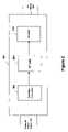
- FIG. 2illustrates schematically some of the components in one embodiment of the VSD 104 .
- the VSD 104can have three stages: a rectifier/converter stage 202 , a DC link stage 204 and an inverter stage 206 .
- the rectifier/converter 202converts the fixed frequency, fixed magnitude AC voltage from the AC power source 102 into DC voltage.
- the DC link 204filters the DC power from the converter 202 and provides energy storage components such as capacitors and/or inductors.
- the inverter 206converts the DC voltage from the DC link 204 into variable frequency, variable magnitude AC voltage for the motor 106 .
- the VSD 104can provide a variable output voltage and variable frequency to the motor 106 , the motor can be operated at a variety of different conditions, for instance in constant flux or constant volts/Hz mode depending on the particular load of the motor.
- a control panel, microprocessor or controllercan provide control signals to the VSD 104 to control the operation of the VSD 104 and motor 106 to provide the optimal operational setting for the VSD 104 and motor 106 , depending on the particular sensor readings received by the control panel.
- a control panel, microprocessor or controllercan provide control signals to the VSD 104 to control the operation of the VSD 104 and motor 106 to provide the optimal operational setting for the VSD 104 and motor 106 , depending on the particular sensor readings received by the control panel.
- the control panel 308can adjust the output voltage and frequency of the VSD 104 to correspond to changing conditions in the refrigeration system, i.e., the control panel 308 can increase or decrease the output voltage and frequency of the VSD 104 in response to increasing or decreasing load conditions on the compressor 302 in order to obtain a desired operating speed of the motor 106 and a desired output load of the compressor 302 .
- the rectifier/converter 202is a three-phase pulse width modulated boost rectifier having insulated gate bipolar transistors (IGBTs) to provide a boosted DC voltage to the DC link 204 to obtain a maximum RMS output voltage from the VSD 104 greater than the input voltage of the VSD 104 .
- the converter 202can be a diode or thyristor rectifier, possibly coupled to a boost DC/DC converter to provide a boosted DC voltage to the DC link 204 in order to obtain an output voltage from the VSD 104 greater than the input voltage of the VSD 104 .
- the rectifier/converter 202may be a passive diode or thyristor rectifier without voltage-boosting capability.
- the VSD 104can provide output voltages and frequencies that are at least 1.04 times and 3 times the fixed voltage and fixed frequency, respectively, provided to the VSD 104 . Furthermore, it is to be understood that the VSD 104 can incorporate different components from those shown in FIG. 2 so long as the VSD 104 can provide the motor 106 with appropriate output voltages and frequencies.
- the VSD 104can also include a precharge system (not shown) that can control the rise of the DC link voltage from 0 V to a value close to the peak of the AC line voltage to avoid a large inrush current in the VSD 104 when the AC voltage is first applied to the VSD 104 , which inrush current can be damaging to the components of the VSD 104 .
- the precharge systemcan include a precharge contactor that is used to connect precharge resistors between the input AC power source 102 and the rectifier/converter 202 or, sometimes, between the output of the rectifier/converter 202 and the DC link 204 . These precharge resistors limit the inrush current to a manageable level.
- precharge resistorsare excluded from the circuit by opening the precharge contactor, and the input AC power source 102 is connected directly to the converter 202 by the closing of another contactor, referred to as the supply contactor.
- the supply contactorremains closed during the operation of the system.
- precharge meansmay be incorporated into the design of the rectifier/converter 202 , through the use of the appropriate power semiconductor devices, coupled together with the appropriate precharge control means.
- the VSD 104can provide the HVAC&R system with power having about a unity power factor.
- the ability of the VSD 104 to adjust both the voltage and frequency received by the motor 106 to be higher or lower than the fixed line voltage and fixed line frequency received by the VSD 104permits the HVAC&R system to be operated on a variety of foreign and domestic power grids without having to alter the motor 106 or the VSD 104 for different power sources.
- the motor 106is preferably an induction motor that is capable of being driven at variable speeds.
- the induction motorcan have any suitable pole arrangement including two poles, four poles or six poles.
- the induction motoris used to drive a load, preferably a compressor of a refrigeration system as shown in FIG. 3 .
- the HVAC, refrigeration or liquid chiller system 300includes a compressor 302 , a condenser 304 , an evaporator 306 , and a control panel 308 .
- the control panel 308can include a variety of different components such as an analog to digital (A/D) converter, a microprocessor, a non-volatile memory, and an interface board, to control operation of the refrigeration system 300 .
- the control panel 308can also be used to control the operation of the VSD 104 and the motor 106 .
- the conventional refrigeration system 300includes many other features that are not shown in FIG. 3 . These features have been purposely omitted to simplify the drawing for ease of illustration.
- Compressor 302compresses a refrigerant vapor and delivers the vapor to the condenser 304 through a discharge line.
- the compressor 302is preferably a centrifugal compressor, but can be any suitable type of compressor, e.g., screw compressor, reciprocating compressor, etc.
- the refrigerant vapor delivered by the compressor 302 to the condenser 304enters into a heat exchange relationship with a fluid, e.g., air or water, and undergoes a phase change to a refrigerant liquid as a result of the heat exchange relationship with the fluid.
- the condensed liquid refrigerant from condenser 304flows through an expansion device (not shown) to an evaporator 306 .
- the evaporator 306can include connections for a supply line and a return line of a cooling load.
- a secondary liquide.g., water, ethylene, calcium chloride brine or sodium chloride brine, travels into the evaporator 306 via return line and exits the evaporator 306 via supply line.
- the liquid refrigerant in the evaporator 306enters into a heat exchange relationship with the secondary liquid to lower the temperature of the secondary liquid.
- the refrigerant liquid in the evaporator 306undergoes a phase change to a refrigerant vapor as a result of the heat exchange relationship with the secondary liquid.
- the vapor refrigerant in the evaporator 306exits the evaporator 306 and returns to the compressor 302 by a suction line to complete the cycle. It is to be understood that any suitable configuration of condenser 304 and evaporator 306 can be used in the system 300 , provided that the appropriate phase change of the refrigerant in the condenser 304 and evaporator 306 is obtained.
- the HVAC, refrigeration or liquid chiller system 300can include many other features that are not shown in FIG. 3 . These features have been purposely omitted to simplify the drawing for ease of illustration. Furthermore, while FIG. 3 illustrates the HVAC, refrigeration or liquid chiller system 300 as having one compressor connected in a single refrigerant circuit, it is to be understood that the system 300 can have multiple compressors, powered by a single VSD, connected into each of one or more refrigerant circuits.
- the control panel 308incorporates a compressor control unit 406 (see FIG. 4 ) that determines and implements the position of a mechanical loading device for the compressor, for example, the pre-rotation vanes in a centrifugal compressor or the slide valve in a screw compressor.
- the control panel 308also controls the speed of the compressor 302 and the motor 106 , in response to cooling demand signals generated by the control panel 308 for the chiller system.
- the control panel 308sends the motor speed command to the inverter control unit 404 (see FIG. 4 .), which controls the inverter 206 to output the voltage and frequency to the motor 106 to produce the desired compressor speed.
- the inverter control unit 404preferably uses a vector control algorithm to control the speed of the motor 106 via direct torque control, by separately and independently controlling flux-producing and torque-producing components of the motor current.
- the DC link voltage, V DC , DC link voltage first setpoint, V STPT1 , DC link voltage first threshold V TH1 , DC link voltage second setpoint V STPT2 and DC link voltage cutout threshold V UNDERare DC values, where V STP1 >V TH1 >V STPT2 >V UNDER and the sensed input AC line voltage V INAC and input AC voltage threshold V TH — IN are RMS values.
- the preferred method of the present inventiongenerally comprises a two-step operating mode to provide ride-through during a voltage sag at the input to the VSD 104 .
- the rectifier/converter 202in this embodiment a boost rectifier regulates the DC link voltage to its rated value, as if under normal full voltage operation.
- the boost rectifiercompensates for the input AC voltage sag by increasing the input AC current into the boost rectifier, to maintain the DC link voltage at its setpoint (V STPT1 ).
- the boost rectifiercontinues to compensate for the sag in voltage by increasing the input current until it reaches a predetermined current limit.
- the second step of the methodcommences as two substantially simultaneous responses, first by unloading the compressor and second by supplying power to the DC link from the stored energy in the rotating mass of the motor and compressor.
- the compressor control unit 406actuates the mechanical unloading device of the compressor 302 to minimize the power consumed by the refrigeration load from the DC link capacitors and the inertia of the rotating mass of the motor rotor and compressor. While the mechanical load is being uncoupled by the compressor control unit 406 in order to conserve the energy stored in the rotating masses, the inverter control unit 404 switches from the motor speed control mode to DC link voltage control mode and controls the magnitude of the DC link voltage to a level of V STPT2 by controlling the motor speed.
- microprocessor or controller 308to provide the optimal operational setting for the VSD 104 and motor 106 depending on the particular sensor readings received by the control panel 308 is ignored by the VSD 104 .
- the rotor speed of the motor 106decreases during the ride-through, while the DC link voltage is maintained at V STPT2 . If the energy stored in the rotating mass continues to deplete prior to the restoration of the line input voltage to normal range, the DC link voltage will drop below a predetermined threshold, denoted as V UNDER , and the system will shut down.
- each invertermay have its own threshold V TH1 (e.g. V TH1a , V TH1b , V TH1c , where a, b, c stand for different inverters) and its own setpoint V SPT2 (e.g. V SPT2a , V SPT2b , V SPT2c ).
- V TH1e.g. V TH1a , V TH1b , V TH1c , where a, b, c stand for different inverters
- V SPT2e.g. V SPT2a , V SPT2b , V SPT2c
- the VSDincludes an Active Rectifier 202 which may be a pulse width modulated boost rectifier or other boost rectifier type.
- the DC link stage 204provides a control signal V DC at a node 400 , which is transmitted to the rectifier control unit 402 and the inverter control unit 404 .
- Control units 402 and 404also receive other control signals in addition to the DC link voltage, which are omitted in this Figure for ease of illustration.
- Control units 402 and 404are typically located inside the VSD cabinet, but may be located within the control panel 308 , or may be separately mounted on the respective equipment.
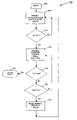
- a flow diagram 500generally illustrating one aspect of the method of the present invention begins in step 502 representing the system initialization. After the system is initialized it runs in normal operation as shown in step 504 provided the line voltage from the AC power source is near the nominal line voltage—i.e., no voltage sag—or the line voltage is beginning to sag below the nominal line voltage but the input current into the boost rectifier is below the current limit value and the DC link voltage is maintained at the setpoint V STPT1 .
- the boost rectifieris regulating the DC link voltage in step 504 a ; the inverter continues as normal to regulate the speed of the compressor in step 504 b ; and monitoring of the DC link voltage is performed by the control hardware and software in step 504 c (See FIG. 6 ). Steps 504 a – 504 c may be carried out concurrently or in sequence as shown in step 504 . The order indicated in FIG. 6 is for illustrative purposes only.
- the input current of the boost rectifieris equal to or less than the RMS current limit value of the boost rectifier in step 504 .
- V DCis compared to a predetermined threshold value V TH1 .
- the magnitude of V TH1is less than the nominal setpoint of the DC link voltage V STPT1 .
- V STP1950 V
- V TH1could be selected as 900 V. If V DC is less than V TH1 , this indicates that boost rectifier has reached its current limit and is no longer capable of regulating the DC link voltage to its setpoint value, and hence the system proceeds to step 508 ( FIGS. 7 & 8 ) to unload the compressor 302 , disable the boost rectifier 202 and precharge devices, and transition the inverter 206 to control the DC link voltage; Otherwise, the system returns to step 504 .
- Monitoring of the DC link voltage V DCmay be performed continuously or in sequence, and is indicated as a discrete step herein if a change in the value of V DC triggers a response in the system.
- Steps 508 a – 508 care carried out in Step 508 as illustrated in FIG. 7 .
- the compressor control unit 406mechanically unloads the compressor in step 508 a through actuation of the vanes in a centrifugal compressor or through the actuation of a slide valve in a screw compressor.
- the stored rotational energy in the motoris conserved for the ride through operation, as described below, and minimal rotational energy is expended to the refrigerant load of the chiller system 300 .
- the thermal energy stored in the refrigerant loop and secondary evaporative cooling loopis used to provide the necessary cooling to the HVAC&R system load.
- step 508 bthe IGBTs in the boost rectifier are disabled, and in step 508 c the precharge devices associated with the boost rectifier are disabled.
- the systemis now in the second stage of Phase 2 ride-through operation, described in steps 510 a – 510 c . Steps 508 a – 508 c may be carried out concurrently or sequentially.
- Steps 510 a – 510 care also carried out in step 508 .
- the inverteris striving to regulate the DC link voltage to a nominal value V STP2 .
- the value chosen for V STPT2is lower than the value chosen for V TH1 .
- V STPT2may be 850 V.
- the inverteris operated as a rectifier by the inverter control unit 404 .
- the energy stored in the rotating mass of the motor 106 and compressor 302flows in the reverse direction from normal motor operation, through the inverter 206 to the DC link 204 .
- the motor 106 and compressor 302effectively become a generator supplying power to the DC link.
- the DC link voltageis supported by energy stored in the electro-mechanical load comprising the motor 106 and compressor 302 .
- Capacitors(not shown) that are connected to the DC link for storing electrical energy are maintained in a charged state by the energy flowing through the inverter 206 from the motor 106 .
- the boost rectifieris disabled, so that all of the energy supplied to the DC link is provided through the inverter from the stored energy in the motor 106 and compressor 302 .
- the DC link 204is thus isolated from the input power source, and control hardware and software monitor the DC link voltage V DC in step 510 b , and the input line voltage V INAC in step 510 c .
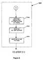
- Steps 510 a – 510 cmay be carried out concurrently or sequentially in step 508 , and the order indicated in FIG. 8 is for illustration purposes only. Step 508 continues until one of the following occurs in steps 512 or 516 shown in FIG. 5A .
- step 512the DC link voltage V DC is being continuously monitored, and if V DC decreases below a predetermined fault threshold voltage V UNDER (which is lower than V STPT2 ), a system fault is indicated.
- V UNDERwhich is lower than V STPT2
- V STPT2a system fault is indicated.
- the VSDis immediately shut down in step 514 .
- step 516the input line voltage V INAC is monitored at the input power source. If V INAC is greater than the predetermined input line threshold voltage V TH — IN , this indicates that the voltage sag condition no longer exists, and the system proceeds to step 518 to reset the system to normal operation. As shown in FIG. 9 , steps 518 a – 518 e are carried out in step 518 .
- step 518 aprecharge devices at the front end of the VSD are enabled to control the increase of the DC link voltage.
- steps 518 b and 518 cthe boost rectifier switches are enabled to further increase the DC link voltage to a predetermined value V STPT1 .
- step 518 dinverter control mode is transferred back to controlling the speed of the motor from the command received from the control panel, microprocessor or controller to provide the optimal operational setting for the VSD 104 and motor 106 depending on the particular sensor readings received by the control panel, and the DC link is again controlled by the rectifier control unit 402 .
- step 518 ethe compressor is mechanically loaded. The system then resumes regular operation in step 504 .
- the boost rectifierremains enabled during the entire ride-through, supplying current to the capacitors of the DC link 202 concurrently with the regeneration of energy from the motor 106 .
- the initial steps 502 through 506 of this alternate methodremain the same as illustrated in FIGS. 5A and 6 , discussed above.
- V DCis less than V TH1
- step 506the system proceeds to step 608 ; otherwise, the system returns to step 504 .
- V STP1950 V
- V TH1could be selected as 900 V.
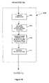
- Steps 508 , 516 and 518are replaced by steps 608 , 616 and 618 as described below.
- Steps 508 a , 510 a , 608 a and 510 care carried out in step 608 shown in FIG. 10 .
- the compressor control unit 406mechanically unloads the compressor in the same manner described above.
- the inverter control unit 404begins to regulate the DC link voltage V DC to the value V STP2 and stops regulating the speed of the compressor motor 106 by ignoring the command received from the control panel, microprocessor or controller that provides the optimal operational setting for the VSD 104 and motor 106 depending on the particular sensor readings received by the control panel.
- the value chosen for V STP2is lower than the value chosen for V TH1 .
- V STP2may be 850 V.
- the boost rectifiercontinues to strive to regulate the DC link to the value V STPT1 operating in current limit, in contrast with the method set forth in FIG. 7 .
- Steps 508 a , 510 b and 510 cmay be carried out concurrently or sequentially in step 608 , and the order indicated in FIG. 10 is for illustration purposes only.
- step 510 athe inverter is operating as a rectifier to regulate the DC link voltage to a predetermined value V STPT2 .
- the DC link voltageis supported both by the energy conducted through the rectifier/converter and by the energy stored in the electromechanical load comprising the motor 106 and compressor 302 .
- the boost rectifierin step 608 a , remains active at its current limit and is also striving to regulate the DC link voltage, but to the higher setpoint value of V STPT1 .
- the operation in current limitprevents the boost rectifier from actually being able to achieve V STPT1 at its output.
- the Active Rectifiercan supply sufficient energy to permit V STPT1 be achieved.
- the boost rectifier's voltage control loopis saturated when operating in current limit (which prevents system instability when both the boost rectifier and the inverter operate in closed loop trying to control DC link voltage), but power continues to flow from the input AC line into the DC link.
- poweris supplied to the DC link stage from both the input voltage source through the converter, and from the load through the inverter, permitting the maximum energy to be retained during the voltage sag and thus maximizing the ride-through capability of the system.
- the alternate methodproceeds to step 512 as described in FIG. 5A above and also shown in FIG. 5B , until reaching step 616 .
- step 616the DC link voltage V DC is compared with the V TH1 limit and a decision is made to either continue to loop back to Phase 2 operation or cease ride-through operation at step 618 . If V DC is greater than V TH1 , the Active Rectifier is no longer operating in current limit, which indicates that the input line voltage has recovered to within a predetermined percentage of the rated line voltage and the inverter control unit has reverted back to controlling the speed of the motor 106 in accordance with the command received from the control panel, microprocessor or controller that provides the optimal operational setting for the VSD 104 and motor 106 depending on the particular sensor readings received by the control panel. In step 618 the compressor 302 is mechanically loaded. The system then resumes regular operation in step 504 .
- control algorithmbe embodied in a computer program(s) and executed by a microprocessor located in the VSD 104
- the control algorithmmay be implemented and executed using digital and/or analog hardware by those skilled in the art. If hardware is used to execute the control algorithm, the corresponding configuration of the VSD 104 can be changed to incorporate the necessary components and to remove any components that may no longer be required.
- the converter 202 of the VSD 104may be a passive rectifier—i.e., a diode or thyristor rectifier for converting the AC input power to DC power for the DC link stage. While the method of using a passive rectifier/converter 202 provides less ride through capability than the active rectifier/converter method, there is still an improved ride through achieved as a result of the unloading of the refrigerant load and the regeneration of energy from the motor/compressor load to the DC link 204 . When a passive rectifier is used, the method described in FIG. 5 is implemented, with ride through effectively beginning in step 508 , wherein the DC link voltage has decayed below the threshold voltage V TH1 . In FIG.
- step 508 band in FIG. 9 step 518 b , action is taken toward the passive rectifier rather than an active rectifier.
- the DC link voltagecannot be controlled to a specific setpoint such as V STP1 through the input converter, but rather the DC link voltage magnitude is a function of the passive rectification of the input AC line voltage.
- the magnitude of V TH1is chosen to be at a level that is lower than the minimum expected DC voltage resulting from rectification of the input line voltage, over the operating input voltage range of the system.
- V STPT2is chosen to be less than V TH1 and the inverter control unit 404 regulates the DC link voltage V DC to the value V STPT2 during the voltage sag.
- the system and method of the present inventiondoes not require the sensing of motor speed to monitor and respond to voltage sag conditions, which reduces the cost and increases the reliability of the system.
- the controlis achieved through sensing of the DC link voltage, input AC line voltage, input currents and motor currents.
Landscapes
- Engineering & Computer Science (AREA)
- Power Engineering (AREA)
- Control Of Ac Motors In General (AREA)
- Inverter Devices (AREA)
Abstract
Description
Claims (33)
Priority Applications (4)
| Application Number | Priority Date | Filing Date | Title |
|---|---|---|---|
| US11/218,757US7081734B1 (en) | 2005-09-02 | 2005-09-02 | Ride-through method and system for HVACandR chillers |
| US11/422,668US7332885B2 (en) | 2005-09-02 | 2006-06-07 | Ride-through method and system for HVAC&R chillers |
| PCT/US2006/022716WO2007030176A1 (en) | 2005-09-02 | 2006-06-12 | Ride-through method and system for hvac&r chillers |
| TW95122485ATWI303691B (en) | 2005-09-02 | 2006-06-22 | Ride-through method and system for hvac&r chillers |
Applications Claiming Priority (1)
| Application Number | Priority Date | Filing Date | Title |
|---|---|---|---|
| US11/218,757US7081734B1 (en) | 2005-09-02 | 2005-09-02 | Ride-through method and system for HVACandR chillers |
Related Child Applications (1)
| Application Number | Title | Priority Date | Filing Date |
|---|---|---|---|
| US11/422,668Continuation-In-PartUS7332885B2 (en) | 2005-09-02 | 2006-06-07 | Ride-through method and system for HVAC&R chillers |
Publications (1)
| Publication Number | Publication Date |
|---|---|
| US7081734B1true US7081734B1 (en) | 2006-07-25 |
Family
ID=36687091
Family Applications (1)
| Application Number | Title | Priority Date | Filing Date |
|---|---|---|---|
| US11/218,757Expired - LifetimeUS7081734B1 (en) | 2005-09-02 | 2005-09-02 | Ride-through method and system for HVACandR chillers |
Country Status (1)
| Country | Link |
|---|---|
| US (1) | US7081734B1 (en) |
Cited By (20)
| Publication number | Priority date | Publication date | Assignee | Title |
|---|---|---|---|---|
| US20070263331A1 (en)* | 2006-04-28 | 2007-11-15 | Leuthen John M | Systems and Methods for Power Ride-Through in Variable Speed Drives |
| US20090109713A1 (en)* | 2007-10-30 | 2009-04-30 | Johnson Controls Technology Company | Variable speed drive |
| US20090241575A1 (en)* | 2008-03-28 | 2009-10-01 | Johnson Controls Technology Company | Cooling member |
| US20100071396A1 (en)* | 2007-01-22 | 2010-03-25 | Johnson Controls Technology Company | Cooling member |
| US20100083692A1 (en)* | 2008-10-03 | 2010-04-08 | Johnson Controls Technology Company | Variable speed drive for permanent magnet motor |
| US7746020B2 (en) | 2007-01-22 | 2010-06-29 | Johnson Controls Technology Company | Common mode & differential mode filter for variable speed drive |
| US20100229580A1 (en)* | 2007-05-08 | 2010-09-16 | Johnson Controls Technology Company | Variable speed drive |
| US20110141774A1 (en)* | 2007-10-30 | 2011-06-16 | Johnson Controls Technology Company | Variable speed drive |
| WO2011018542A3 (en)* | 2009-08-10 | 2012-08-09 | Ingeteam Technology, S. A. | Method for controlling an energy conversion system |
| US20130026958A1 (en)* | 2010-05-04 | 2013-01-31 | Johnson Controls Technology Company | Variable speed drive |
| US20130076128A1 (en)* | 2011-09-28 | 2013-03-28 | Caterpillar, Inc. | Active Switching Frequency Modulation |
| US20130099705A1 (en)* | 2011-10-25 | 2013-04-25 | Fanuc Corporation | Motor driving device having reactive current instruction generating unit |
| US20130107401A1 (en)* | 2011-10-31 | 2013-05-02 | Trane International Inc. | Time Delay With Control Voltage Sensing |
| CN104052199A (en)* | 2013-03-15 | 2014-09-17 | 艾默生环境优化技术有限公司 | System And Method For Protection Of A Compressor With An Aluminum Winding Motor |
| US20150219378A1 (en)* | 2012-08-30 | 2015-08-06 | Johnsoon Controls Technology Company | Variable speed drive control for chiller coast-through |
| US9407194B2 (en) | 2013-03-15 | 2016-08-02 | Emerson Climate Technologies, Inc. | System and method for protection of a compressor with an aluminum winding motor |
| US20170117731A1 (en)* | 2014-04-23 | 2017-04-27 | Hitachi Automotive Systems, Ltd. | Power source device |
| CN107370389A (en)* | 2016-05-12 | 2017-11-21 | 洛克威尔自动控制技术股份有限公司 | For overcoming the electric power coversion system and its operating method of abnormal grid condition |
| US20190238081A1 (en)* | 2016-10-05 | 2019-08-01 | Johnson Controls Technology Company | Variable speed drive with a battery |
| CN112977069A (en)* | 2021-03-19 | 2021-06-18 | 黄冈格罗夫氢能汽车有限公司 | Pre-charging and discharging system of hydrogen energy automobile and pre-charging and high-voltage discharging method thereof |
Citations (51)
| Publication number | Priority date | Publication date | Assignee | Title |
|---|---|---|---|---|
| US3593103A (en)* | 1969-03-04 | 1971-07-13 | Gen Electric | Inverter system with automatic ridethrough |
| US4308491A (en)* | 1980-05-05 | 1981-12-29 | Square D Company | Automatic fault protection system for power recovery control |
| US4339779A (en)* | 1980-08-27 | 1982-07-13 | A.C. Manufacturing Company | Apparatus for preventing damage by voltage interruption |
| US4663536A (en)* | 1985-03-04 | 1987-05-05 | Precise Power Corporation | A.C. motor-generator |
| EP0272776A2 (en) | 1986-12-19 | 1988-06-29 | Glentronic Limited | Three-phase supply system |
| EP0283954A2 (en) | 1987-03-20 | 1988-09-28 | Ranco Incorporated Of Delaware | Compressor drive system and air conditioner using the same |
| EP0313366A2 (en) | 1987-10-23 | 1989-04-26 | Sundstrand Corporation | Variable speed constant frequency power system with boost converter auxiliary output |
| US4879475A (en)* | 1986-10-03 | 1989-11-07 | W. Schlafhorst & Co. | Device and method for maintaining a voltage level in a control circuit |
| EP0422221A1 (en) | 1988-05-05 | 1991-04-17 | AKIBA, Seiichi | Self-active type generation system |
| US5081368A (en) | 1989-04-28 | 1992-01-14 | Atlas Energy Systems, Inc. | Uninterruptible power supply with a variable speed drive driving an induction motor/generator |
| US5123080A (en)* | 1987-03-20 | 1992-06-16 | Ranco Incorporated Of Delaware | Compressor drive system |
| US5127085A (en)* | 1991-04-01 | 1992-06-30 | General Motors Corporation | Ride-through protection circuit for a voltage source inverter traction motor drive |
| US5227943A (en)* | 1990-12-24 | 1993-07-13 | Hughes Aircraft Company | Power fault protection for high momentum systems |
| WO1993014559A1 (en) | 1992-01-21 | 1993-07-22 | Nartron Corporation | Pulse width modulation power circuit |
| US5298848A (en) | 1990-11-28 | 1994-03-29 | Hitachi, Ltd. | Large capacity variable speed PWM spatial vector type sub-harmonic system for driving AC electric motor |
| US5304900A (en)* | 1991-07-31 | 1994-04-19 | Howa Machinery, Ltd. | Spinning frame |
| US5410230A (en) | 1992-05-27 | 1995-04-25 | General Electric Company | Variable speed HVAC without controller and responsive to a conventional thermostat |
| US5646458A (en)* | 1996-02-22 | 1997-07-08 | Atlas Energy Systems, Inc. | Uninterruptible power system with a flywheel-driven source of standby power |
| WO1997032168A1 (en) | 1996-02-27 | 1997-09-04 | Shaw David N | Boosted air source heat pump |
| US5747955A (en) | 1995-03-31 | 1998-05-05 | Quinton Instrument Company | Current sensing module for a variable speed AC motor drive for use with a treadmill |
| US5796234A (en) | 1996-01-19 | 1998-08-18 | Gas Research Institute | Variable speed motor apparatus and method for forming same from a split capacitor motor |
| US5869946A (en) | 1997-02-27 | 1999-02-09 | Stmicroelectronics, Inc. | PWM control of motor driver |
| US5936855A (en) | 1996-09-03 | 1999-08-10 | Mercury Electric Corporation | Harmonic correction of 3-phase rectifiers and converters |
| US5969966A (en) | 1995-09-08 | 1999-10-19 | Kabushiki Kaisha Yaskawa Denki | Power converting apparatus and method using a multiple three-phase PWM cycloconverter system |
| US6005362A (en)* | 1998-02-13 | 1999-12-21 | The Texas A&M University Systems | Method and system for ride-through of an adjustable speed drive for voltage sags and short-term power interruption |
| US6072302A (en) | 1998-08-26 | 2000-06-06 | Northrop Grumman Corporation | Integrated control system and method for controlling mode, synchronization, power factor, and utility outage ride-through for micropower generation systems |
| US6118676A (en) | 1998-11-06 | 2000-09-12 | Soft Switching Technologies Corp. | Dynamic voltage sag correction |
| US6133716A (en)* | 1998-10-23 | 2000-10-17 | Statordyne, Inc. | High-efficiency high-power uninterrupted power system |
| US6160722A (en) | 1999-08-13 | 2000-12-12 | Powerware Corporation | Uninterruptible power supplies with dual-sourcing capability and methods of operation thereof |
| US6239513B1 (en)* | 2000-02-24 | 2001-05-29 | Design Power Solutions International | Emergency supplemental power supply for outage protection of critical electric loads |
| US6262544B1 (en)* | 2000-02-28 | 2001-07-17 | Delphi Technologies, Inc. | Four quadrant motor operation using DC bus current sensing |
| US6276148B1 (en) | 2000-02-16 | 2001-08-21 | David N. Shaw | Boosted air source heat pump |
| US6313600B1 (en) | 2000-02-29 | 2001-11-06 | Robicon Corporation | Control method and apparatus for insufficient input voltage in an AC drive |
| US6348775B1 (en) | 1999-05-11 | 2002-02-19 | Borealis Technical Limited | Drive wave form synchronization for induction motors |
| US6487096B1 (en) | 1997-09-08 | 2002-11-26 | Capstone Turbine Corporation | Power controller |
| US20030015873A1 (en)* | 2001-01-10 | 2003-01-23 | Claude Khalizadeh | Transient ride-through or load leveling power distribution system |
| US6516922B2 (en)* | 2001-05-04 | 2003-02-11 | Gregory Shadkin | Self-generating elevator emergency power source |
| US6559562B1 (en)* | 2001-12-14 | 2003-05-06 | Ssi Power, Llc | Voltage sag and over-voltage compensation device with pulse width modulated autotransformer |
| US20030098668A1 (en)* | 2001-11-27 | 2003-05-29 | York International Corporation | Control loop and method for variable speed drive ride - through capability improvement |
| US20030218887A1 (en)* | 2002-04-30 | 2003-11-27 | Kojori Hassan A. | Synchronous and bi-directional variable frequency power conversion systems |
| US6720674B1 (en)* | 2001-03-12 | 2004-04-13 | Indigo Energy, Inc. | Device for prevention of power interruptions |
| US6768284B2 (en) | 2002-09-30 | 2004-07-27 | Eaton Corporation | Method and compensation modulator for dynamically controlling induction machine regenerating energy flow and direct current bus voltage for an adjustable frequency drive system |
| US6777898B2 (en)* | 2002-09-03 | 2004-08-17 | William A. Peterson | Methods and apparatus for maintaining synchronization of a polyphase motor during power interruptions |
| US6801019B2 (en) | 2000-01-28 | 2004-10-05 | Newage International Limited | AC power generating system |
| US20050057210A1 (en)* | 2003-09-09 | 2005-03-17 | Mitsuo Ueda | Converter circuit and motor driving apparatus |
| US20050068001A1 (en)* | 2001-11-23 | 2005-03-31 | Danfoss Drives A/S | Frequency converter for different mains voltages |
| US6954366B2 (en)* | 2003-11-25 | 2005-10-11 | Electric Power Research Institute | Multifunction hybrid intelligent universal transformer |
| US20050225270A1 (en)* | 2004-04-12 | 2005-10-13 | York International Corporation | System and method for controlling a variable speed drive |
| US20050258795A1 (en)* | 2004-05-18 | 2005-11-24 | Choi Christopher W | Energy management apparatus and method for injection molding systems |
| US20050278071A1 (en)* | 2004-06-14 | 2005-12-15 | Durham Ormonde G Iii | Adaptable HVAC; AC motor speed, air temperature and air quality control system |
| US20050283277A1 (en)* | 2004-06-18 | 2005-12-22 | Schulz Harry W | Method and system for improving pump efficiency and productivity under power disturbance conditions |
- 2005
- 2005-09-02USUS11/218,757patent/US7081734B1/ennot_activeExpired - Lifetime
Patent Citations (57)
| Publication number | Priority date | Publication date | Assignee | Title |
|---|---|---|---|---|
| US3593103A (en)* | 1969-03-04 | 1971-07-13 | Gen Electric | Inverter system with automatic ridethrough |
| US4308491A (en)* | 1980-05-05 | 1981-12-29 | Square D Company | Automatic fault protection system for power recovery control |
| US4339779A (en)* | 1980-08-27 | 1982-07-13 | A.C. Manufacturing Company | Apparatus for preventing damage by voltage interruption |
| US4663536A (en)* | 1985-03-04 | 1987-05-05 | Precise Power Corporation | A.C. motor-generator |
| US4879475A (en)* | 1986-10-03 | 1989-11-07 | W. Schlafhorst & Co. | Device and method for maintaining a voltage level in a control circuit |
| EP0272776A2 (en) | 1986-12-19 | 1988-06-29 | Glentronic Limited | Three-phase supply system |
| EP0283954A2 (en) | 1987-03-20 | 1988-09-28 | Ranco Incorporated Of Delaware | Compressor drive system and air conditioner using the same |
| US5123080A (en)* | 1987-03-20 | 1992-06-16 | Ranco Incorporated Of Delaware | Compressor drive system |
| EP0313366A2 (en) | 1987-10-23 | 1989-04-26 | Sundstrand Corporation | Variable speed constant frequency power system with boost converter auxiliary output |
| EP0422221A1 (en) | 1988-05-05 | 1991-04-17 | AKIBA, Seiichi | Self-active type generation system |
| US5081368A (en) | 1989-04-28 | 1992-01-14 | Atlas Energy Systems, Inc. | Uninterruptible power supply with a variable speed drive driving an induction motor/generator |
| US5298848A (en) | 1990-11-28 | 1994-03-29 | Hitachi, Ltd. | Large capacity variable speed PWM spatial vector type sub-harmonic system for driving AC electric motor |
| US5227943A (en)* | 1990-12-24 | 1993-07-13 | Hughes Aircraft Company | Power fault protection for high momentum systems |
| US5127085A (en)* | 1991-04-01 | 1992-06-30 | General Motors Corporation | Ride-through protection circuit for a voltage source inverter traction motor drive |
| US5304900A (en)* | 1991-07-31 | 1994-04-19 | Howa Machinery, Ltd. | Spinning frame |
| WO1993014559A1 (en) | 1992-01-21 | 1993-07-22 | Nartron Corporation | Pulse width modulation power circuit |
| US5410230A (en) | 1992-05-27 | 1995-04-25 | General Electric Company | Variable speed HVAC without controller and responsive to a conventional thermostat |
| US5592058A (en) | 1992-05-27 | 1997-01-07 | General Electric Company | Control system and methods for a multiparameter electronically commutated motor |
| US5747955A (en) | 1995-03-31 | 1998-05-05 | Quinton Instrument Company | Current sensing module for a variable speed AC motor drive for use with a treadmill |
| US5969966A (en) | 1995-09-08 | 1999-10-19 | Kabushiki Kaisha Yaskawa Denki | Power converting apparatus and method using a multiple three-phase PWM cycloconverter system |
| US5796234A (en) | 1996-01-19 | 1998-08-18 | Gas Research Institute | Variable speed motor apparatus and method for forming same from a split capacitor motor |
| US5646458A (en)* | 1996-02-22 | 1997-07-08 | Atlas Energy Systems, Inc. | Uninterruptible power system with a flywheel-driven source of standby power |
| WO1997032168A1 (en) | 1996-02-27 | 1997-09-04 | Shaw David N | Boosted air source heat pump |
| US5936855A (en) | 1996-09-03 | 1999-08-10 | Mercury Electric Corporation | Harmonic correction of 3-phase rectifiers and converters |
| US5869946A (en) | 1997-02-27 | 1999-02-09 | Stmicroelectronics, Inc. | PWM control of motor driver |
| US6487096B1 (en) | 1997-09-08 | 2002-11-26 | Capstone Turbine Corporation | Power controller |
| US6005362A (en)* | 1998-02-13 | 1999-12-21 | The Texas A&M University Systems | Method and system for ride-through of an adjustable speed drive for voltage sags and short-term power interruption |
| US6072302A (en) | 1998-08-26 | 2000-06-06 | Northrop Grumman Corporation | Integrated control system and method for controlling mode, synchronization, power factor, and utility outage ride-through for micropower generation systems |
| US6316918B1 (en)* | 1998-08-26 | 2001-11-13 | Satcon Technology Corporation | Integrated control system and method for controlling mode, synchronization, power factor, and utility outage ride-through for micropower generation systems |
| US6411065B1 (en)* | 1998-08-26 | 2002-06-25 | Satcon Technology Corporation | Integrated control system and method for controlling mode, synchronization, power factor, and utility outage ride through for micropower generation systems |
| US6133716A (en)* | 1998-10-23 | 2000-10-17 | Statordyne, Inc. | High-efficiency high-power uninterrupted power system |
| US6118676A (en) | 1998-11-06 | 2000-09-12 | Soft Switching Technologies Corp. | Dynamic voltage sag correction |
| US6348775B1 (en) | 1999-05-11 | 2002-02-19 | Borealis Technical Limited | Drive wave form synchronization for induction motors |
| US6160722A (en) | 1999-08-13 | 2000-12-12 | Powerware Corporation | Uninterruptible power supplies with dual-sourcing capability and methods of operation thereof |
| US6801019B2 (en) | 2000-01-28 | 2004-10-05 | Newage International Limited | AC power generating system |
| US6276148B1 (en) | 2000-02-16 | 2001-08-21 | David N. Shaw | Boosted air source heat pump |
| US6239513B1 (en)* | 2000-02-24 | 2001-05-29 | Design Power Solutions International | Emergency supplemental power supply for outage protection of critical electric loads |
| US6262544B1 (en)* | 2000-02-28 | 2001-07-17 | Delphi Technologies, Inc. | Four quadrant motor operation using DC bus current sensing |
| US6313600B1 (en) | 2000-02-29 | 2001-11-06 | Robicon Corporation | Control method and apparatus for insufficient input voltage in an AC drive |
| US20030015873A1 (en)* | 2001-01-10 | 2003-01-23 | Claude Khalizadeh | Transient ride-through or load leveling power distribution system |
| US6720674B1 (en)* | 2001-03-12 | 2004-04-13 | Indigo Energy, Inc. | Device for prevention of power interruptions |
| US6516922B2 (en)* | 2001-05-04 | 2003-02-11 | Gregory Shadkin | Self-generating elevator emergency power source |
| US20050068001A1 (en)* | 2001-11-23 | 2005-03-31 | Danfoss Drives A/S | Frequency converter for different mains voltages |
| US6686718B2 (en)* | 2001-11-27 | 2004-02-03 | York International Corp. | Control loop and method for variable speed drive ride-through capability improvement |
| US20030098668A1 (en)* | 2001-11-27 | 2003-05-29 | York International Corporation | Control loop and method for variable speed drive ride - through capability improvement |
| US6559562B1 (en)* | 2001-12-14 | 2003-05-06 | Ssi Power, Llc | Voltage sag and over-voltage compensation device with pulse width modulated autotransformer |
| US20030218887A1 (en)* | 2002-04-30 | 2003-11-27 | Kojori Hassan A. | Synchronous and bi-directional variable frequency power conversion systems |
| US6850426B2 (en)* | 2002-04-30 | 2005-02-01 | Honeywell International Inc. | Synchronous and bi-directional variable frequency power conversion systems |
| US6777898B2 (en)* | 2002-09-03 | 2004-08-17 | William A. Peterson | Methods and apparatus for maintaining synchronization of a polyphase motor during power interruptions |
| US6768284B2 (en) | 2002-09-30 | 2004-07-27 | Eaton Corporation | Method and compensation modulator for dynamically controlling induction machine regenerating energy flow and direct current bus voltage for an adjustable frequency drive system |
| US20050057210A1 (en)* | 2003-09-09 | 2005-03-17 | Mitsuo Ueda | Converter circuit and motor driving apparatus |
| US6954366B2 (en)* | 2003-11-25 | 2005-10-11 | Electric Power Research Institute | Multifunction hybrid intelligent universal transformer |
| US20050225270A1 (en)* | 2004-04-12 | 2005-10-13 | York International Corporation | System and method for controlling a variable speed drive |
| US20050258795A1 (en)* | 2004-05-18 | 2005-11-24 | Choi Christopher W | Energy management apparatus and method for injection molding systems |
| US20050278071A1 (en)* | 2004-06-14 | 2005-12-15 | Durham Ormonde G Iii | Adaptable HVAC; AC motor speed, air temperature and air quality control system |
| US20050283277A1 (en)* | 2004-06-18 | 2005-12-22 | Schulz Harry W | Method and system for improving pump efficiency and productivity under power disturbance conditions |
| US20050281681A1 (en)* | 2004-06-18 | 2005-12-22 | Anderson Robb G | Method and system for improving pump efficiency and productivity under power disturbance conditions |
Non-Patent Citations (5)
| Title |
|---|
| A novel ride-through system for adjustable-speed drives using common-mode voltage□□Yonk-Seok Kim; Seung-Ki Sul;□□Industry Applications, IEEE Transactions on□□vol. 37, Issue 5, Sep.-Oct. 2001 pp. 1373-1382.* |
| Annabelle Van Zyl, Rene Spee, Alex Faveluke, and Shibashis Bhowmik; Voltage Sag Ride-Through for Adjustable-Speed Drives With Active Rectifiers; IEEE Transactions on Industry Applications; Nov./Dec. 1998; vol. 34, Issue No. 6. |
| Annette Von Jouanne, Prasad N. Enjeti, and Basudeb Banerjee; Assessment of Ride-Through Alternatives for Adjustable-Speed Drives; IEEE Transactions on Industry Applications; Jul./Aug. 1999; vol. 35, Issue No. 4. |
| Extended ride-through capability for matrix converter drives with continuous motor synchronization Wiechmann, E.P.; Burgos, R.P.; Rodriguez, J.R.; Power Electronics, Machines and Drives, 2002. International Conference on (Conf. Publ. No. 487) Jun. 4-7, 2002 pp. 189-194.* |
| Ride-through alternatives for adjustable-speed drives-computational analysis, Belchior, F.N.; Oliviera, J.C.; Leao, P.C.A.; Souto, O.C.N., Industrial Electronics, 2003. ISIE '03. 2003 IEEE International Symposium on vol. 2 Jun. 9-11, 2003, pp. 1032-1036 vol. 2.* |
Cited By (48)
| Publication number | Priority date | Publication date | Assignee | Title |
|---|---|---|---|---|
| US7607896B2 (en)* | 2006-04-28 | 2009-10-27 | Baker Hughes Incorporated | Systems and methods for power ride-through in variable speed drives |
| US20070263331A1 (en)* | 2006-04-28 | 2007-11-15 | Leuthen John M | Systems and Methods for Power Ride-Through in Variable Speed Drives |
| US7876561B2 (en) | 2007-01-22 | 2011-01-25 | Johnson Controls Technology Company | Cooling systems for variable speed drives and inductors |
| US8014110B2 (en) | 2007-01-22 | 2011-09-06 | Johnson Controls Technology Company | Variable speed drive with integral bypass contactor |
| US20100071396A1 (en)* | 2007-01-22 | 2010-03-25 | Johnson Controls Technology Company | Cooling member |
| US8495890B2 (en) | 2007-01-22 | 2013-07-30 | Johnson Controls Technology Company | Cooling member |
| US7764041B2 (en) | 2007-01-22 | 2010-07-27 | Johnson Controls Technology Company | System and method to extend synchronous operation of an active converter in a variable speed drive |
| US7746020B2 (en) | 2007-01-22 | 2010-06-29 | Johnson Controls Technology Company | Common mode & differential mode filter for variable speed drive |
| US20100229580A1 (en)* | 2007-05-08 | 2010-09-16 | Johnson Controls Technology Company | Variable speed drive |
| US8004803B2 (en)* | 2007-05-08 | 2011-08-23 | Johnson Controls Technology Company | Variable speed drive |
| US8174853B2 (en) | 2007-10-30 | 2012-05-08 | Johnson Controls Technology Company | Variable speed drive |
| US20090109713A1 (en)* | 2007-10-30 | 2009-04-30 | Johnson Controls Technology Company | Variable speed drive |
| US7957166B2 (en) | 2007-10-30 | 2011-06-07 | Johnson Controls Technology Company | Variable speed drive |
| US20110141774A1 (en)* | 2007-10-30 | 2011-06-16 | Johnson Controls Technology Company | Variable speed drive |
| US8149579B2 (en) | 2008-03-28 | 2012-04-03 | Johnson Controls Technology Company | Cooling member |
| US20090241575A1 (en)* | 2008-03-28 | 2009-10-01 | Johnson Controls Technology Company | Cooling member |
| US8353174B1 (en) | 2008-10-03 | 2013-01-15 | Johnson Controls Technology Company | Control method for vapor compression system |
| US20100083692A1 (en)* | 2008-10-03 | 2010-04-08 | Johnson Controls Technology Company | Variable speed drive for permanent magnet motor |
| US20100084935A1 (en)* | 2008-10-03 | 2010-04-08 | Johnson Controls Technology Company | Permanent magnet synchronous motor and drive system |
| US8193756B2 (en) | 2008-10-03 | 2012-06-05 | Johnson Controls Technology Company | Variable speed drive for permanent magnet motor |
| US8258664B2 (en) | 2008-10-03 | 2012-09-04 | Johnson Controls Technology Company | Permanent magnet synchronous motor and drive system |
| US8286439B2 (en) | 2008-10-03 | 2012-10-16 | Johnson Control Technology Company | Variable speed drive for permanent magnet motor |
| US8336323B2 (en) | 2008-10-03 | 2012-12-25 | Johnson Controls Technology Company | Variable speed drive with pulse-width modulated speed control |
| US20100083693A1 (en)* | 2008-10-03 | 2010-04-08 | Johnson Controls Technology Company | Variable speed drive with pulse-width modulated speed control |
| US20100085000A1 (en)* | 2008-10-03 | 2010-04-08 | Johnson Controls Technology Company | Variable speed drive for permanent magnet motor |
| WO2011018542A3 (en)* | 2009-08-10 | 2012-08-09 | Ingeteam Technology, S. A. | Method for controlling an energy conversion system |
| US9024559B2 (en)* | 2010-05-04 | 2015-05-05 | Johnson Controls Technology Company | Variable speed drive |
| US20130026958A1 (en)* | 2010-05-04 | 2013-01-31 | Johnson Controls Technology Company | Variable speed drive |
| US20130076128A1 (en)* | 2011-09-28 | 2013-03-28 | Caterpillar, Inc. | Active Switching Frequency Modulation |
| US20130099705A1 (en)* | 2011-10-25 | 2013-04-25 | Fanuc Corporation | Motor driving device having reactive current instruction generating unit |
| US9048733B2 (en)* | 2011-10-25 | 2015-06-02 | Fanuc Corporation | Motor driving device having reactive current instruction generating unit |
| US20130107401A1 (en)* | 2011-10-31 | 2013-05-02 | Trane International Inc. | Time Delay With Control Voltage Sensing |
| US9601919B2 (en)* | 2011-10-31 | 2017-03-21 | Trane International Inc. | Time delay with control voltage sensing |
| US11480373B2 (en)* | 2012-08-30 | 2022-10-25 | Johnson Controls Tyco IP Holdings LLP | Variable speed drive control for chiller coast-through |
| US20150219378A1 (en)* | 2012-08-30 | 2015-08-06 | Johnsoon Controls Technology Company | Variable speed drive control for chiller coast-through |
| US10337781B2 (en)* | 2012-08-30 | 2019-07-02 | Johnson Controls Technology Company | Variable speed drive control for chiller coast-through |
| CN104052199B (en)* | 2013-03-15 | 2017-09-08 | 艾默生环境优化技术有限公司 | Compressor, the method and apparatus for protecting compressor |
| US9407194B2 (en) | 2013-03-15 | 2016-08-02 | Emerson Climate Technologies, Inc. | System and method for protection of a compressor with an aluminum winding motor |
| CN104052199A (en)* | 2013-03-15 | 2014-09-17 | 艾默生环境优化技术有限公司 | System And Method For Protection Of A Compressor With An Aluminum Winding Motor |
| US20170117731A1 (en)* | 2014-04-23 | 2017-04-27 | Hitachi Automotive Systems, Ltd. | Power source device |
| US10461553B2 (en)* | 2014-04-23 | 2019-10-29 | Hitachi Automotive Systems, Ltd. | Power source device |
| CN107370389A (en)* | 2016-05-12 | 2017-11-21 | 洛克威尔自动控制技术股份有限公司 | For overcoming the electric power coversion system and its operating method of abnormal grid condition |
| US9847733B2 (en)* | 2016-05-12 | 2017-12-19 | Rockwell Automation Technologies, Inc. | Power conversion system with DC bus regulation for abnormal grid condition ride through |
| CN107370389B (en)* | 2016-05-12 | 2019-06-28 | 罗克韦尔自动化技术公司 | For overcoming the power conversion system and its operating method of abnormal grid condition |
| EP3244521B1 (en)* | 2016-05-12 | 2021-08-11 | Rockwell Automation Technologies, Inc. | Power conversion system with dc bus regulation for abnormal grid condition ride through |
| US20190238081A1 (en)* | 2016-10-05 | 2019-08-01 | Johnson Controls Technology Company | Variable speed drive with a battery |
| US10812005B2 (en)* | 2016-10-05 | 2020-10-20 | Johnson Controls Technology Company | Variable speed drive with a battery |
| CN112977069A (en)* | 2021-03-19 | 2021-06-18 | 黄冈格罗夫氢能汽车有限公司 | Pre-charging and discharging system of hydrogen energy automobile and pre-charging and high-voltage discharging method thereof |
Similar Documents
| Publication | Publication Date | Title |
|---|---|---|
| US7332885B2 (en) | Ride-through method and system for HVAC&R chillers | |
| US7081734B1 (en) | Ride-through method and system for HVACandR chillers | |
| US7207183B2 (en) | System and method for capacity control in a multiple compressor chiller system | |
| US7193826B2 (en) | Motor disconnect arrangement for a variable speed drive | |
| CN101218738B (en) | Variable speed drive for a chiller system | |
| US20070151272A1 (en) | Electronic control transformer using DC link voltage | |
| US7231773B2 (en) | Startup control system and method for a multiple compressor chiller system | |
| US20070056300A1 (en) | System and method for capacity control in a multiple compressor chiller system | |
| KR20080081256A (en) | Capacity control system and method of multi-stage compressor refrigeration system | |
| WO2007030176A1 (en) | Ride-through method and system for hvac&r chillers | |
| JP2009095096A (en) | Active converter / inverter device and refrigeration system using the same |
Legal Events
| Date | Code | Title | Description |
|---|---|---|---|
| AS | Assignment | Owner name:YORK INTERNATIONAL CORPORATION, PENNSYLVANIA Free format text:ASSIGNMENT OF ASSIGNORS INTEREST;ASSIGNORS:JADRIC, IVAN;SCHNETZKA, HAROLD ROBERT;REEL/FRAME:016954/0097;SIGNING DATES FROM 20050830 TO 20050901 | |
| STCF | Information on status: patent grant | Free format text:PATENTED CASE | |
| FEPP | Fee payment procedure | Free format text:PAYOR NUMBER ASSIGNED (ORIGINAL EVENT CODE: ASPN); ENTITY STATUS OF PATENT OWNER: LARGE ENTITY | |
| FPAY | Fee payment | Year of fee payment:4 | |
| FPAY | Fee payment | Year of fee payment:8 | |
| MAFP | Maintenance fee payment | Free format text:PAYMENT OF MAINTENANCE FEE, 12TH YEAR, LARGE ENTITY (ORIGINAL EVENT CODE: M1553) Year of fee payment:12 | |
| AS | Assignment | Owner name:JOHNSON CONTROLS TYCO IP HOLDINGS LLP, WISCONSIN Free format text:ASSIGNMENT OF ASSIGNORS INTEREST;ASSIGNOR:YORK INTERNATIONAL CORPORATION;REEL/FRAME:058562/0695 Effective date:20210617 | |
| AS | Assignment | Owner name:JOHNSON CONTROLS TYCO IP HOLDINGS LLP, WISCONSIN Free format text:NUNC PRO TUNC ASSIGNMENT;ASSIGNOR:YORK INTERNATIONAL CORPORATION;REEL/FRAME:058956/0981 Effective date:20210806 | |
| AS | Assignment | Owner name:TYCO FIRE & SECURITY GMBH, SWITZERLAND Free format text:ASSIGNMENT OF ASSIGNORS INTEREST;ASSIGNOR:JOHNSON CONTROLS TYCO IP HOLDINGS LLP;REEL/FRAME:072275/0058 Effective date:20240201 |