US7081693B2 - Energy harvesting for wireless sensor operation and data transmission - Google Patents
Energy harvesting for wireless sensor operation and data transmissionDownload PDFInfo
- Publication number
- US7081693B2 US7081693B2US10/379,223US37922303AUS7081693B2US 7081693 B2US7081693 B2US 7081693B2US 37922303 AUS37922303 AUS 37922303AUS 7081693 B2US7081693 B2US 7081693B2
- Authority
- US
- United States
- Prior art keywords
- recited
- energy
- storage device
- sensor
- data
- Prior art date
- Legal status (The legal status is an assumption and is not a legal conclusion. Google has not performed a legal analysis and makes no representation as to the accuracy of the status listed.)
- Expired - Lifetime, expires
Links
- 238000003306harvestingMethods0.000titleclaimsabstractdescription86
- 230000005540biological transmissionEffects0.000titleclaimsdescription21
- 238000003860storageMethods0.000claimsabstractdescription124
- 238000012544monitoring processMethods0.000claimsabstractdescription26
- 239000003990capacitorSubstances0.000claimsdescription82
- 238000012806monitoring deviceMethods0.000claimsdescription26
- 230000006854communicationEffects0.000claimsdescription22
- 238000004891communicationMethods0.000claimsdescription22
- 239000000463materialSubstances0.000claimsdescription14
- 239000000835fiberSubstances0.000claimsdescription13
- 238000005259measurementMethods0.000claimsdescription13
- 238000012546transferMethods0.000claimsdescription7
- 238000000034methodMethods0.000claimsdescription6
- 230000005611electricityEffects0.000claimsdescription5
- 238000005452bendingMethods0.000claimsdescription4
- 238000013500data storageMethods0.000claimsdescription4
- 230000036541healthEffects0.000claimsdescription4
- 230000033001locomotionEffects0.000claimsdescription4
- 230000008569processEffects0.000claimsdescription4
- 239000000919ceramicSubstances0.000claimsdescription3
- 238000009825accumulationMethods0.000claimsdescription2
- 150000003839saltsChemical class0.000claimsdescription2
- 229910001285shape-memory alloyInorganic materials0.000claimsdescription2
- 239000010409thin filmSubstances0.000claimsdescription2
- XLYOFNOQVPJJNP-UHFFFAOYSA-NwaterSubstancesOXLYOFNOQVPJJNP-UHFFFAOYSA-N0.000claimsdescription2
- 230000008713feedback mechanismEffects0.000claims2
- 230000009471actionEffects0.000claims1
- 230000015556catabolic processEffects0.000claims1
- 238000006731degradation reactionMethods0.000claims1
- 229920000642polymerPolymers0.000claims1
- 230000009466transformationEffects0.000claims1
- 238000010586diagramMethods0.000description17
- 230000007774longtermEffects0.000description16
- 238000012423maintenanceMethods0.000description16
- 230000008901benefitEffects0.000description13
- 238000006243chemical reactionMethods0.000description10
- 230000009467reductionEffects0.000description7
- 239000013078crystalSubstances0.000description6
- 238000005516engineering processMethods0.000description5
- 230000006870functionEffects0.000description5
- 230000006872improvementEffects0.000description5
- 238000012360testing methodMethods0.000description5
- 238000013480data collectionMethods0.000description4
- 238000013461designMethods0.000description4
- 230000005284excitationEffects0.000description4
- 230000001939inductive effectEffects0.000description4
- 230000000737periodic effectEffects0.000description4
- 238000004458analytical methodMethods0.000description3
- 230000003750conditioning effectEffects0.000description3
- 238000007599dischargingMethods0.000description3
- 238000013459approachMethods0.000description2
- 230000007175bidirectional communicationEffects0.000description2
- 230000008878couplingEffects0.000description2
- 238000010168coupling processMethods0.000description2
- 238000005859coupling reactionMethods0.000description2
- 238000011161developmentMethods0.000description2
- 230000018109developmental processEffects0.000description2
- 238000004146energy storageMethods0.000description2
- 239000011888foilSubstances0.000description2
- 238000007689inspectionMethods0.000description2
- 238000012986modificationMethods0.000description2
- 230000004048modificationEffects0.000description2
- 239000003921oilSubstances0.000description2
- 239000007787solidSubstances0.000description2
- 238000004804windingMethods0.000description2
- 241001640117CallaeumSpecies0.000description1
- 241000288673ChiropteraSpecies0.000description1
- HBBGRARXTFLTSG-UHFFFAOYSA-NLithium ionChemical compound[Li+]HBBGRARXTFLTSG-UHFFFAOYSA-N0.000description1
- XUIMIQQOPSSXEZ-UHFFFAOYSA-NSiliconChemical compound[Si]XUIMIQQOPSSXEZ-UHFFFAOYSA-N0.000description1
- XAGFODPZIPBFFR-UHFFFAOYSA-NaluminiumChemical compound[Al]XAGFODPZIPBFFR-UHFFFAOYSA-N0.000description1
- 229910052782aluminiumInorganic materials0.000description1
- 230000004888barrier functionEffects0.000description1
- 230000006399behaviorEffects0.000description1
- 230000009286beneficial effectEffects0.000description1
- 238000009529body temperature measurementMethods0.000description1
- 238000002485combustion reactionMethods0.000description1
- 239000000356contaminantSubstances0.000description1
- 238000005260corrosionMethods0.000description1
- 230000007797corrosionEffects0.000description1
- 238000013016dampingMethods0.000description1
- 238000001514detection methodMethods0.000description1
- 238000006073displacement reactionMethods0.000description1
- 230000000694effectsEffects0.000description1
- 238000005265energy consumptionMethods0.000description1
- 230000007613environmental effectEffects0.000description1
- 238000002474experimental methodMethods0.000description1
- 239000000446fuelSubstances0.000description1
- 239000007943implantSubstances0.000description1
- 238000009434installationMethods0.000description1
- 238000009413insulationMethods0.000description1
- 230000010354integrationEffects0.000description1
- 229910001416lithium ionInorganic materials0.000description1
- 238000004519manufacturing processMethods0.000description1
- 230000007246mechanismEffects0.000description1
- 238000004377microelectronicMethods0.000description1
- 238000013001point bendingMethods0.000description1
- 238000010248power generationMethods0.000description1
- 230000003449preventive effectEffects0.000description1
- 238000012545processingMethods0.000description1
- 230000002000scavenging effectEffects0.000description1
- 239000004065semiconductorSubstances0.000description1
- 229910052710siliconInorganic materials0.000description1
- 239000010703siliconSubstances0.000description1
- 230000003595spectral effectEffects0.000description1
- 238000009987spinningMethods0.000description1
- 238000006467substitution reactionMethods0.000description1
- 229910052715tantalumInorganic materials0.000description1
- GUVRBAGPIYLISA-UHFFFAOYSA-Ntantalum atomChemical compound[Ta]GUVRBAGPIYLISA-UHFFFAOYSA-N0.000description1
- 230000036413temperature senseEffects0.000description1
Images


Classifications
- H—ELECTRICITY
- H02—GENERATION; CONVERSION OR DISTRIBUTION OF ELECTRIC POWER
- H02N—ELECTRIC MACHINES NOT OTHERWISE PROVIDED FOR
- H02N2/00—Electric machines in general using piezoelectric effect, electrostriction or magnetostriction
- H02N2/18—Electric machines in general using piezoelectric effect, electrostriction or magnetostriction producing electrical output from mechanical input, e.g. generators
- H02N2/186—Vibration harvesters
- B—PERFORMING OPERATIONS; TRANSPORTING
- B60—VEHICLES IN GENERAL
- B60C—VEHICLE TYRES; TYRE INFLATION; TYRE CHANGING; CONNECTING VALVES TO INFLATABLE ELASTIC BODIES IN GENERAL; DEVICES OR ARRANGEMENTS RELATED TO TYRES
- B60C23/00—Devices for measuring, signalling, controlling, or distributing tyre pressure or temperature, specially adapted for mounting on vehicles; Arrangement of tyre inflating devices on vehicles, e.g. of pumps or of tanks; Tyre cooling arrangements
- B60C23/02—Signalling devices actuated by tyre pressure
- B60C23/04—Signalling devices actuated by tyre pressure mounted on the wheel or tyre
- B60C23/0408—Signalling devices actuated by tyre pressure mounted on the wheel or tyre transmitting the signals by non-mechanical means from the wheel or tyre to a vehicle body mounted receiver
- B60C23/041—Means for supplying power to the signal- transmitting means on the wheel
- B60C23/0411—Piezoelectric generators
- H—ELECTRICITY
- H02—GENERATION; CONVERSION OR DISTRIBUTION OF ELECTRIC POWER
- H02J—CIRCUIT ARRANGEMENTS OR SYSTEMS FOR SUPPLYING OR DISTRIBUTING ELECTRIC POWER; SYSTEMS FOR STORING ELECTRIC ENERGY
- H02J7/00—Circuit arrangements for charging or depolarising batteries or for supplying loads from batteries
- H02J7/32—Circuit arrangements for charging or depolarising batteries or for supplying loads from batteries for charging batteries from a charging set comprising a non-electric prime mover rotating at constant speed
- H—ELECTRICITY
- H02—GENERATION; CONVERSION OR DISTRIBUTION OF ELECTRIC POWER
- H02J—CIRCUIT ARRANGEMENTS OR SYSTEMS FOR SUPPLYING OR DISTRIBUTING ELECTRIC POWER; SYSTEMS FOR STORING ELECTRIC ENERGY
- H02J7/00—Circuit arrangements for charging or depolarising batteries or for supplying loads from batteries
- H02J7/34—Parallel operation in networks using both storage and other DC sources, e.g. providing buffering
- H02J7/345—Parallel operation in networks using both storage and other DC sources, e.g. providing buffering using capacitors as storage or buffering devices
- H—ELECTRICITY
- H10—SEMICONDUCTOR DEVICES; ELECTRIC SOLID-STATE DEVICES NOT OTHERWISE PROVIDED FOR
- H10N—ELECTRIC SOLID-STATE DEVICES NOT OTHERWISE PROVIDED FOR
- H10N30/00—Piezoelectric or electrostrictive devices
- H10N30/30—Piezoelectric or electrostrictive devices with mechanical input and electrical output, e.g. functioning as generators or sensors
- H10N30/304—Beam type
- H10N30/306—Cantilevers
Definitions
- This inventiongenerally relates to collecting and transmitting data. More particularly, it relates to a device for sensing, storing and transmitting data. Even more particularly, it relates to a device that can that can be attached to a structure or live subject and that can harvest energy from its environment to power sensing, storing and transmitting data about the structure or live subject.
- the devicesinclude a flexible piezoelectric foil stave to harness sole-bending energy and a reinforced piezoelectric dimorph to capture heel-strike energy. They also report on prototype development of radio frequency identification (RFID) tags which are self powered by a pair of sneakers.6
- RFIDradio frequency identification
- Low power sensorshave been developed, as described on commonly assigned U.S. patent application Ser. No. 09/731,066, to Arms, that includes a sensing unit for attaching to a structure or live subject for sensing a parameter of the structure or live subject.
- the sensing unitincludes a sensor, a data storage device, and a transmitting device.
- the data storage deviceis for storing data from the sensor.
- Poweris provided by a power supply such as a rechargeable battery or fuel cell.
- the rechargeable batterycan be recharged by inductive coupling from an external control unit.
- the systemuses microminiature, multichannel, wireless programmable addressable sensing modules to sample data from a variety of sensors.
- the nodesare inductively powered, eliminating the need for batteries or interconnecting lead wires.
- Wireless sensorshave the advantage of eliminating the cost of installing wiring. They also improve reliability by eliminating connector problems. However, wireless sensors still require system power in order to operate. If power outages occur, critical data collected by the sensors may be lost. In some cases, sensors may be hardwired to a vehicle's power system. In other cases however, the need to hard wire to a power system defeats the advantages of wireless sensors, and this may be unacceptable for many applications. Most prior wireless structural monitoring systems have therefore relied on continuous power supplied by batteries. For example, in 1972, Weiss developed a battery powered inductive strain measurement system, which measured and counted strain levels for aircraft fatigue. Traditional batteries, however, become depleted and must be periodically replaced or recharged, adding an additional maintenance task that must be performed. This is particularly a problem for monitors used for a condition based maintenance program since it adds additional maintenance for the condition based monitoring system itself.
- a sensing systemincludes a component for harvesting ambient mechanical or magnetic energy and converts this energy into electrical energy;
- the data collection devicecan provide information about the environment using energy harvested from the environment.
- the data collection devicedoes not itself require maintenance for replacing or recharging batteries.
- a device for powering a load from an ambient source of energycomprises an energy harvesting device for harvesting energy from the ambient source of energy wherein the rate energy is harvested from the ambient source of energy is below that required for directly powering the load.
- a storage deviceis connected to the energy harvesting device. The storage device receives electrical energy from the energy harvesting device and is for storing the electrical energy.
- a controlleris connected to the storage device is for monitoring the amount of electrical energy stored in the storage device and for switchably connecting the storage device to the load when the stored energy exceeds a first threshold.
- Another aspect of the inventionis an energy harvesting system comprising a piezoelectric transducer and a rectifier.
- the systemalso includes a reactive device having a high impedance approximately matching impedance of the piezoelectric transducer at its operating frequency for efficiently transferring energy from the piezoelectric transducer to the reactive device.
- the systemalso includes a low impedance high capacity storage device.
- the systemalso includes a circuit for monitoring voltage across the reactive device, and for transferring the charge from the reactive device to the low impedance high capacity storage device when the voltage across the reactive device reaches a specified voltage value.
- the devicefor sensing temperature or pressure in a tire.
- the deviceincludes a tire and a PZT mounted on the tire.
- the devicealso includes a circuit for harvesting energy from the PZT, wherein the circuit comprises an element having an impedance approximately matching impedance of the PZT.
- the devicealso includes a sensing module connected to the circuit, the sensing module including a sensor and a circuit for wirelessly transmitting sensor information.
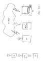
- FIG. 1 ais a perspective view of an energy harvesting addressable wireless sensing node of the present invention mounted on a machine or structure;
- FIG. 1 bis a perspective view of components within the energy harvesting addressable wireless sensing node
- FIG. 1 cis a perspective view of the energy harvesting cantilever shown in FIG. 1 b with variable mass for tuning to a vibration frequency of the machine or structure;
- FIG. 1 dis a schematic diagram of a base station for receiving said wirelessly transmitted information
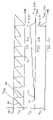
- FIG. 2is an alternative embodiment in which a large sheet of PZT fiber is embedded in material, such as a hull of ship so vibration or strain energy transmitted through the hull can be harvested;
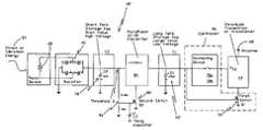
- FIGS. 3 a , 3 bare block diagrams of one embodiment of an energy harvesting addressable wireless sensing node of the present invention in which energy is harvested by a PZT;
- FIG. 4is a block diagram of an alternate embodiment of an energy harvesting addressable wireless sensing node of the present invention in which energy is harvested from a power transmission line;
- FIG. 5is a block diagram of the wireless sensing module shown in FIGS. 3 a , 3 b;
- FIG. 6 ais a timing diagram of voltage across capacitor C 2 of FIG. 11 ;
- FIG. 6 bis a timing diagram of voltage across capacitor C 1 of FIG. 11 ;
- FIG. 6 cis a timing diagram of voltage across the transmitter of FIG. 11 showing how charge gradually stored in long term storage capacitor C 1 is used to briefly power the transmitter or transceiver;
- FIG. 7is a cross sectional view of a tire having an energy harvesting device of the present invention to power transmitting pressure and temperature sense data;
- FIG. 8is a schematic diagram showing a receiver mounted in a vehicle that receives signals indicating tire sensor data transmitted by each of the tires on the vehicle;
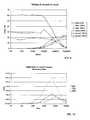
- FIG. 9is a diagram showing data from an experimental test showing that the PZT provided the same low current output as load resistance was varied from 100 ohms to 50 Kohms;
- FIG. 10is a diagram showing data from the experimental test showing that the optimum load impedance, that delivers maximum power, was found to be about 500 Kohms;
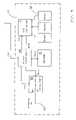
- FIG. 11 ais a block diagram of an improved embodiment of an energy harvesting addressable wireless sensing node of the present invention having an additional stage of charge storage, monitoring, switching, and impedance conversion between the rectifier and the controller of FIG. 3 a;
- FIG. 11 bis a schematic diagram showing more detail than the block diagram of FIG. 11 a ;
- FIG. 12is a schematic diagram showing a wireless web enabled sensor network (WWSN) system that requires very little power.
- WWSNwireless web enabled sensor network
- the present inventorsrecognized that substantial efficiency in collecting, storing, and transmitting data from wireless sensors could be provided by harvesting energy from the environment.
- This inventionis aimed at developing a new class of sensing systems that can wirelessly report data without the need for maintaining or replacing batteries. Instead, the sensing systems rely on harvesting vibration, strain energy, or magnetic coupled energy from the local environment for conversion to electrical power for storage and use to collect, store, or transmit data by the sensing system.
- machines, structures, and live subjectscan be monitored without the need for replacing or recharging batteries or for a battery maintenance schedule.
- Truly smart structures and machineswill thus be able to autonomously report their condition throughout their operating life without the mechanism used for reporting the data itself requiring maintenance.
- the systemcan be used to run and communicate with actuators as well as sensors.
- Condition based maintenanceprovides a more accurate and cost effective maintenance program for equipment or structures.
- the present inventionreduces unnecessary preventive maintenance for the devices used to monitor.
- the present inventionprovides the components necessary to realize the potential benefits of condition based monitoring, including information acquisition, analysis, storage, and reporting technologies that substantially lower power requirements, making energy harvesting for condition based maintenance a realistic source of energy.
- condition based maintenanceand another important use for the present invention is aboard ships where batteryless sensing systems may be used for wirelessly monitoring oil debris or oil condition, tank & hull corrosion, combustion pressure, water-lubricated-bearing wear, and machine condition.
- the inventioncan also be used for integrated, hierarchical machinery diagnostics & prognostics; machinery diagnostics & prognostics; open systems architecture condition based maintenance; human—computer interface condition based maintenance; and diagnostic of insulation, such as wire and windings.
- the inventioncan also be used on land vehicles or aircraft for purposes such as to monitor and report tire temperature and pressure. In each case mechanical energy, such as the energy of vibration of the vehicle, can be used to power the sensor and its storage or communications apparatus.
- Batteries, and the additional maintenance burden for replacing or recharging batteries,are avoided in the present invention by providing wireless sensing network systems which can harvest energy from the local environment to provide the power needed for their own operation.
- PZT fibershave recently been made commercially available at low cost for active damping of sporting equipment, such as baseball bats, tennis rackets, and skis (Advanced Cerametrics, Lambertville, N.J., www.advancedcerametrics.com/piezo_fiber.html). These fibers may be directly bonded to a straining element or structure to generate electrical energy that can be harvested. Major advantages of these fiber piezoelectric materials is that they can tolerate the loss of many individual fibers in a bundle and still function well. Since they are in mass production, they may be obtained readily and at relatively low cost. Because of these advantages the present invention describes the use of these PZT materials for energy harvesting wireless sensor networks. However, other devices and other sources of ambient energy can also be used.
- the present inventorshave used single crystal and PZT fibers to create working energy harvesting prototypes that provide sufficient energy to power StrainLink wireless sensor transmitters available from MicroStrain, Inc. (StrainLink, http://www.microstrain.com/slink.html).
- Energy harvesting addressable wireless sensing node 18can be attached to machine or structure 19 that is subject to vibration, as shown in FIG. 1 a .
- PZT 20is mounted to cantilever 22 which can be tuned with variable mass 24 , as shown in FIGS. 1 b and 1 c , to provide a device resonance frequency close to the vibration frequency of machine or structure 19 , thereby optimizing energy harvesting.
- PZT 20can be either a crystal or a fiber.
- Cantilever 22is mounted on PC board 25 in enclosure 26 .
- a large sheet of PZT fiber 27can be embedded in material of hull 28 of ship 30 so vibration or strain energy transmitted through hull 28 can be harvested, as shown in FIG. 2 .
- Large sheets of PZT fiber 27are preferred because tuning is not readily available to harvest the strain energy.
- a structure, such as hull 28 or the deck of a bridgebends only a limited amount, and the bending cannot be tuned as can flexural element by adjusting mass so as to take advantage of resonance frequency to harvest more of the energy.
- the source of mechanical energysuch as machine or structure 19
- the source of mechanical energyis converted to electrical energy in energy harvesting addressable wireless sensing node 18 ′, which includes a miniature electric generator, such as PZT 20 , as shown in FIG. 3 a .
- a miniature electric generatorcan also be provided with a coil and magnet in relative rotational motion, as for example, would be available in the vicinity of spinning machinery or wheels.
- Electrical power generated in PZT 20is rectified in rectifier 40 , stored in electrical storage device 42 , and once sufficient energy has been stored, is provided to a load, such as wireless sensing module 44 , by means of controller 46 .
- a single crystal PZT 20was connected to the circuit shown in FIGS. 3 a , 3 b , while vibration was applied to PZT 20 .
- a DC voltmeter across storage capacitor 42upwards of 20 volts was measured across the capacitor with approximately 0.08 inch deflection of the PZT 20 at a 50 Hz rate.
- PZT 20is inherently a high impedance device which provides a nearly constant current, so the storage capacitor charges linearly with time.
- the Microstrain StrainLink transmitteris also a constant current load, so calculating the discharge uses the same formula.
- a 47 uF cap charged to 16 voltswill supply 2.8 mA for 268 mS discharging to zero volts.
- a low power StrainLink transmittercan be connected as load 44 in the circuit of FIG. 3 a , 3 b and can run for 224 mS before reaching the reset voltage of 2.63 volts. This is enough time to transmit data from several sensors. Obviously a bigger storage capacitance would supply a longer operating time as would any reduction in load current presented by the transmitter. However, a longer time would be needed to charge a larger capacitor. Furthermore, the practicality of such a system is dependant on the continued availability of vibration input energy. Thus, the present device is ideally suited to applications where ambient vibration is continuous for long periods to provide for the self-discharge rate of storage capacitor 42 , to provide power consumed by the circuit used to monitor charge and switch on the load, as well as to power the load.
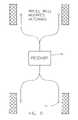
- PZT 20 devicecould be replaced with coil winding 47 a that is closely coupled to power transmission line 47 b that would allow energy in the magnetic field around the transmission line to be harvested, as shown in FIG. 4 .
- Such a configurationcould be used with thermocouples 47 c to measure the temperature of transmission line 47 b and detect an overheated condition in transmission line 47 b .
- the frequency of transmissionsis proportional to current in the transmission line 47 b.
- Wireless sensing module 44includes microcontroller or microprocessor 48 , which controls provision of power to A/D converter 50 , sensors 52 , non-volatile memory 54 , and RF transmitter 56 , as shown in FIG. 5 .
- Sensorscan include such sensors as a temperature sensor, a strain gauge, a pressure sensor, a magnetic field sensor, an accelerometer, or a DVRT.
- microcontroller 48By selectively providing power to or withholding power from these devices microcontroller 48 can achieve substantial energy savings.
- Microcontroller 48also controls flow of data from A/D converter 50 , from sensors 52 , to and from nonvolatile memory 54 and to RF transmitter 56 .
- a transceivercan be provided instead of RF transmitter 56 to enable two way communication, all powered by ambient vibrational energy.
- the strain or vibrational energy 57 from the ambient environmentis provided to PZT transducer 20 mounted on a machine, structure, or live subject, as shown in block diagram form in FIG. 3 a and in schematic form in FIG. 3 b .
- electrical output of PZT 20is rectified in rectifier 40 .
- DC output of rectifier 40charges storage capacitor 42 .
- Controller 46monitors charge stored on storage capacitor 42 , and when sufficient, provides Vcc power to wireless sensing module 44 for transmitting sensor data through antenna 68 to receiver 69 a on base station 69 b ( FIG. 1 d ).
- Receiver 69 acan be a transceiver.
- Controller 46includes monitoring device 70 , and switch Q 1 , which is formed of MOSFET transistor 72 .
- monitoring device 70When voltage across capacitor 42 is sufficient, monitoring device 70 turns on to provide Vcc to wireless sensing module 44 . To reduce leakage and ensure that wireless sensing module 44 remains fully off and does not load storage capacitor 42 when voltage across storage capacitor 42 is below a threshold, transistor 72 is provided. When transistor 72 turns on, ground connection from wireless sensing module 44 is established.
- Transistor 72is needed because when voltage provided by storage capacitor 42 is too low, monitoring device 46 cannot provide its output in a known state. Monitoring device 46 may turn on falsely and load down storage device 42 , preventing it from ever charging up. Monitoring device 46 is not itself a reliable switch unless supply voltage is above a threshold. To provide for operation in the regime when supply voltage is below that threshold, switch 72 is provided to ensure that wireless sensing module 44 remains fully off. Switch 72 connected between wireless sensing module 44 and ground and to has a single threshold.
- monitoring device 70becomes valid at 1.8 volts.
- Switch Q 1 transistor 72turns on at 2.0 V, enabling wireless sensing module 44 when storage capacitor 42 has sufficient charge to operate monitoring device 70 properly and can hold it off.
- monitoring device 70turns on and transfers charge from storage capacitor 42 to power wireless sensing module 44 for a brief period, until voltage discharges back to 2.9 volts, at which point monitoring device 70 turns off further transfer, and monitoring device 70 therefore continues to be in a valid state for subsequent operation, well above the 1.8 volts level needed for proper operation in a determinate state.
- monitoring device 70turns on and connects wireless sensing module 44 to storage device 42 .
- Storage device 42can then recharge from energy supplied from PZT 20 .
- monitoring device 70may not be sufficiently powered to operate correctly. It may not fully disconnect wireless sensing module 44 from storage device 42 , and thus, wireless sensing module 44 may continue to load storage device 42 , preventing it from ever recharging.
- switch 72is provided which disconnects wireless sensing module 44 from ground when potential across storage capacitor 42 falls somewhat below the lower threshold.
- the present inventorsfound that impedance mismatch between PZT 20 and storage capacitor 42 limits the amount of power that can be transferred from PZT 20 to storage capacitor 42 . They recognized that energy transfer was limited by the fact that AC power generated by PZT 20 is presented by the PZT at a very high impedance and at low frequency. They observed that PZT 20 behaves as a constant current source, and that when piezoelectric elements are used to charge capacitors, such as storage capacitor 42 , charging is determined by the short circuit current capability of PZT 20 . When storage capacitor 42 is charged from a constant current source, such as PZT 20 , storage capacitor 42 will charge at a rate proportional to the current provided by the constant current source.
- the present inventorsdeveloped a circuit that efficiently converts power from a high impedance current source, such as PZT 20 , to a low impedance voltage source capable of charging a capacitor or battery storage device.
- the inventorsalso developed an efficient way to determine when enough power has been accumulated and applying that accumulated power to a useful purpose.
- the present inventorsrecognized that if the available power in the piezoelectric element were to be efficiently converted from its low current and high impedance current source to a voltage source, the capacitor could be charged much faster than if the same capacitor were charged directly from the short circuit current of the piezoelectric element without this conversion. For example, if a voltage converter can present a 500K load to the piezoelectric element, approximately matching its impedance, the element will deliver 17.5 volts at 35 uA or 610 microwatts. If this power was then converted down to 100 ohms source impedance, even at 80% efficiency, the charge current would be more than 2.2 mA. By comparison, the output at the same level of excitation of the piezoelectric element when loaded to 100 ohms without a converter, is 6 millivolts at 60 uA or 0.36 microwatts, about 1,700 times less power.
- the inventors of the present inventionconducted empirical tests on a sample of piezoelectric material in order to determine a viable topology of conversion circuit.
- a testwas performed on a sample of highly flexible piezoelectric fiber. The sample was mounted in a 3 point bending jig with a strain gauge attached to the material, and excited to the same strain levels at three different frequencies.
- a decade resistance substitution boxwas used to load the output in order to determine the optimum load impedance for maximum power out of the material under these conditions. The same low current was measured as the load resistance was varied from 100 ohms to 50 Kohms as shown in FIG. 9 .
- the optimum load impedance, that delivers maximum powerwas found to be about 500 Kohms, as shown in FIG. 10 .
- the present inventorsfound that further substantial improvement in energy harvesting is available by adding an impedance converter circuit to the circuit of FIG. 3 a that provide better impedance matching to the high impedance of PZT 20 , while still finally providing the large capacitance needed to power wireless sensing module 44 .
- the improvement to energy harvesting addressable wireless sensing node 18 ′′illustrated in block diagram form in FIG. 11 a and in a schematic diagram in FIG. 11 b , provides an additional stage of charge storage, monitoring, switching, and impedance conversion between rectifier 40 and controller 46 of FIG. 3 a .
- the improvementallows a much larger capacitor or a battery to be used for that long term storage 42 ′, and this enables more information transfer by wireless sensing module 44 .
- PZT 20connected to a source of mechanical energy, such as vibration or strain 57 , produces a high impedance AC voltage in accordance with the strain or vibration 57 applied to PZT element 20 .
- D 1 and D 2( FIG. 11 b ) form Schottky barrier rectifier bridge rectifier 40 that converts the AC voltage from PZT 20 to DC.
- PZT 20charges reactance element 78 , such as small capacitor C 2 along curve 80 until a voltage equal to Vth 3 is reached, as shown in FIG. 11 a and FIG. 6 a.
- Voltage Vth 3is sufficient to turn on switch 2 , transistor 82 which connects DC—DC converter 84 to ground, enabling DC—DC converter 84 to turn on and operate.
- DC—DC converter 84turns on, it converts the high voltage stored on small capacitor C 2 to a low voltage at a low impedance for providing a small boost 86 to the charge on long term storage capacitor 42 ′, capacitor C 1 , as shown along charging curve 88 in FIG. 6B .
- long term storage capacitor C 1is charging
- small capacitor C 2is discharging.
- the discharge of small capacitor C 2is shown along curve 90 in FIG. 6 a , providing the charge to boost the voltage of long term storage capacitor C 1 by the small step 86 shown in FIG. 6 b .
- DC—DC converter 84is a high frequency stepdown DC to DC converter that has a typical quiescent current of 12 uA and is capable of 80% efficiency even with small load current.
- DC—DC converter 84 , U 2is an LT1934-1 (Linear Technology, Milpitas, Calif.). This converter was chosen due to its very low quiescent current.
- resistors R 1 , R 2 , R 3 , and comparator U 1form monitoring device 70 a and also form voltage sensitive switch 70 b that turns off connection to load 44 until enough charge has been accumulated on storage capacitor 42 , 42 ′ to run load 44 .
- Load 44can be multiple wireless sensing module 44 , or an array of such modules, as shown in FIG. 11 b .
- Monitoring device 70 a /voltage sensitive switch 70 bis in an undefined state, however, until at least 1.8 volts is available on its Vcc pin 7 , which is connected to storage device 42 , 42 ′.
- MOSFET switch Q 1is provided to disconnect load 44 until voltage on storage device 42 , 42 ′ has reached 2.0 volts.
- R 2 & R 3set the turn-on threshold V th2 of voltage sensitive switch 70 b to 6.3 volts.
- R 1provides hysteresis to comparator U 1 giving it two thresholds.
- Voltage sensitive switch 70 bnow turns on when voltage on storage device 42 .
- 42 ′reaches the higher threshold V th1 of 6.3 volts and stays on until the voltage on storage device 42 discharges down to V th2 the lower threshold of 2.9 volts.
- Load 44may be a StrainLink transmitter or a data logging transceiver.
- switch Q 1If voltage to switch Q 1 declines too far, switch Q 1 will turn off, and this shuts off transmitter 44 until enough energy is accumulated in storage device 42 ′ to send another burst of data.
- Multiple wireless sensing modules 44 or other devicescan be provided on a network, each powered as described herein with energy harvested from its environment.
- the multiple wireless sensing module 44can transmit on different frequencies or a randomization timer can be provided to add a random amount of time after wake up to reduce probability of collisions during transmission. However, since the time for charging is likely to differ from one wireless sensing module 44 to another, a randomization timer may not be needed.
- Each wireless sensing module 44will transmit an address as well as data.
- Transceiverscan be provided to each wireless sensing module 44 to provide two way communication. Preferably, if a battery is used that is recharged from the environment, sufficient energy will be available so it can wake up periodically to determine if something is being transmitted to it. If not it can go back to sleep mode. If so, it can receive the transmission. All the members can be managed by a broadcast signal or each wireless sensing module 44 can be addressed and programmed individually.
- the present inventorshave applied the energy harvesting system to design a device for embedding in a tire by a tire manufacturer for harvesting energy and for monitoring parameters, such as tire temperature and pressure on a vehicle and for transmitting the data, as shown in FIG. 7 .
- the cross section of tire 100shows the placement of PZT 102 , or several such PZT elements, on or within interior sidewall 104 of tire 100 for gathering strain energy from flexing of tire 100 on rim 101 as the tire rotates.
- PZT 102is connected to provide power to energy harvesting addressable wireless sensing node 106 for transmitting data from temperature and pressure sensors 108 , such as Sensor Nor from Horten, Norway, to report this tire data.
- Energy harvesting addressable wireless sensing node 106can be programmed to provide it with a 128 bit address. With such a large address there are enough combinations possible to allow every tire in the world to have a unique address.
- receiver 110 mounted in the vehiclecan receive a signal indicating tire sensor data for each of the tires on the vehicle, as shown in FIG. 8 .
- a displaycan provide the information to the operator.
- an alarmcan signal when tire pressure or temperature is outside specified limits. Interference from other vehicles can be avoided by displaying only data from tires having known addresses.
- Local antennas 112can be provided in each wheel well (not shown) and the power output of energy harvesting addressable wireless sensing node 106 can be adjusted to provide reliable communications within the wheel well of the vehicle while avoiding interference with transmitters on adjacent vehicles.
- Receiver 110having antennas 112 positioned in each wheel well of the vehicle, can rapidly scan antennas 112 to determine the address and position of each tire on the vehicle. Because of the scanning of the antennas, even if tires are rotated, the display can indicate the location of a tire having a problem. Most modern receivers have the capability of accurately measuring received signal strength with fairly high resolution. In the case of inner and outer wheels in a single wheel well, these received signals can be qualified by received signal strength indication to distinguish the tires in the wheel well, even if they are rotated. Thus, the tire further from the antenna will have the weaker signal strength. In addition, the serial numbers of each tire would also be logged in the receiver flash memory to distinguish tires on the vehicle for feedback to a tire manufacturer.
- One alternative to the tire position problem that does not require scanning or multiple antennas,is to have a technician sequentially scan a bar code on the tires at the time of tire installation on the vehicle, and communicate the tire position information to the automotive communications (CAN) bus or other communications bus within the vehicle, or even directly to the receiver.
- the position informationis provided using a different protocol than the information tires are sending so this information can remain stored in the receiver while other data about the tire changes with each reading.
- one receive antennacould receive data and an identification code from all tires on the vehicle, and the stored table linking identification and tire position can be used to communicate the position, temperature, and pressure of each tire. Interference from transmitters on adjacent vehicles is avoided since they would not have known identification codes.
- the present inventorshave also found ways to reduce power consumption as well as to provide power from energy harvesting. They recognized that power consumed by all of the system's components (sensor, conditioner, processor, data storage, and data transmission) must be compatible with the amount of energy harvested. Minimizing the power required to collect and transmit data correspondingly reduces the demand on the power source. Therefore, the present inventors recognized, minimizing power consumption is as important a goal as maximizing power generation.
- the present inventorshave developed and marketed sensors that require very little power. For example, they have previously reported on micro-miniature differential variable reluctance transducers (DVRT's) capable of completely passive (i.e., no power) peak strain detection. These sensors can be embedded in a material and will continuously monitor for the existence of a damaging strain state. By providing a hermetic seal the sensors can withstand harsh environmental conditions (moisture, salt, and vibration). The sensors can be reset remotely using shape memory alloys and (remotely applied) magnetic field energy, as described in a copending patent application Ser. No. 09/757,909, incorporated herein by reference. The present inventors have also recently developed totally passive strain accumulation sensors, which can be used to monitor fatigue.
- DVRT'smicro-miniature differential variable reluctance transducers
- RFIDradio frequency identification
- the present inventorshave also developed wireless web enabled sensor network (WWSN) systems that require very little power.
- WWSNwireless web enabled sensor network
- FIG. 12This is an ad hoc network that allows thousands of multichannel, microprocessor controlled, uniquely addressed sensing nodes TX to communicate to a central, Ethernet enabled receiver RX with extensible markup language (XML) data output format (http://www.microstrain.com/WWSN.html).
- XMLextensible markup language
- a time division multiple access (TDMA) techniqueis used to control communications. TDMA allows saving power because the nodes can be in sleep mode most of the time. Individual nodes wake up at intervals determined by a randomization timer, and transmit bursts of data.
- a single lithium ion AA batterycan be employed to report temperature from five thermocouples every 30 minutes for a period of five years.
- the XML data formathas the advantage of allowing any user on the local area network (LAN) to view data using a standard Internet browser, such as Netscape or Internet Explorer.
- a standard 802.11b wireless local area network (WLAN)may be employed at the receiver(s) end in order to boost range and to provide bi-directional communications and digital data bridging from multiple local sensing networks that may be distributed over a relatively large area (miles). Further information about a wireless sensor network system developed by the present inventors is in patent application Ser. No. 10/379,224, incorporated herein by reference.
- MicroStrain's Data Logging Transceiver networkhttp://www.microstrain.com/DataLoggingTransceiver.html
- This systememploys addressable sensing nodes which incorporate data logging capabilities, and a bi-directional RF transceiver communications links.
- a central hostorchestrates sample triggering and high speed logging to each node or to all nodes. Data may be processed locally (such as frequency analysis) then uploaded when polled from the central host.
- By providing each sensor node with a 16 bit addressas many as 65,000 multichannel nodes may be hosted by a single computer. Since each node only transmits data when specifically requested, the power usage can be carefully managed by the central host.
- only limited data collected by sensorsmay be transmitted. For example, minimum, maximum and average data can be transmitted to reduce the amount of data transmitted and to thereby save energy. Standard deviation can also be locally calculated and transmitted, saving transmission time and energy.
- a fast Fourier transformcan be locally calculated and only the frequencies of vibration and the magnitude of vibration need be transmitted, rather than the entire waveform, to reduce the amount of information transmitted and to save energy.
- the present inventorsprovided improved designs of each element of the entire measurement system, including the: vibrating/straining structure, piezo harvesting circuit, sensing circuit, microprocessor, on board memory, sensors, and RF data transmitter/transceiver to provide a system that operated with low power.
- the present inventorsthen built a prototype that both improved on the performance of energy harvesting devices and that reduced the energy consumption of each element of the measurement system, including the vibrating/straining structure, piezo harvesting circuit, sensing circuit, microprocessor, on board memory, sensors, and RF data transmitter/transceiver, as shown in FIGS. 3 a , 3 b , 4 and 5 .
- a demonstration energy harvesting circuitwas built using a PZT fiber as its input, as shown in FIGS. 3 a , 3 b .
- the PZT devicegenerates a voltage that is rectified by low forward drop diodes. This rectified voltage is used to charge a storage capacitor.
- the transferis purely a function of the short circuit current of the piezoelectric structure, minus the loss of the rectifier stage, the self discharge of the storage capacitor, and any leakage current in the switch in its ‘off’ state.
- the behavior of this configurationis similar to charging a capacitor from a constant current source.
- the time required to charge the capacitoris inversely proportional to the amplitude of the strain or vibration applied to the PZT element at a given frequency of strain, and also proportional to the frequency of strain at a given amplitude.
- StrainLinkfeatures on-board memory, with user programmable digital filter, gain, and sample rates and with built-in error checking of pulse code modulated (PCM) data. Once programmed, these settings reside in the transmitter's non-volatile memory, which will retain data even if power is removed.
- the StrainLink transmitteris compatible with numerous sensor types including thermocouples, strain gauges, pressure sensors, magnetic field sensors and many others.
- the transmittercan transmit frequency shift keyed (FSK) digital sensor data w/checksum bytes as far as 1 ⁇ 3 mile on just 13 mA of transmit power supply current. During testing, the transmitter operated for approximately 250 mS on the power stored in the charged capacitor. This was ample time for the StrainLink to acquire data from a sensor and transmit multiple redundant data packets containing the sensed data.
- FSKfrequency shift keyed
- Voltage sensing switch 70 bwas implemented using a nano-power comparator with a large amount of hysteresis. Some design difficulties arise when using an electronic device to perform such switching tasks. Voltage sensitive switch 70 b itself needs to be powered from the source it is monitoring. When the available voltage is near zero the state of switch 70 b is indeterminate. This can present a problem when the circuit is initially attempting to charge the capacitor from a completely discharged state. In the demonstration circuit as built, the switch defaults to ‘on’ until the supply voltage to its Vcc exceeds 0.7V, then it will turn off until the intended turn-on voltage level is reached. The transmitter draws constant current, except when the supply voltage is below the transmitter's regulator threshold.
- the voltage sensing switchis still falsely ‘on’ at supply voltages of up to 1 volt, at which point the diode is already conducting power into the load. Drawing current from the storage capacitor at this low voltage slows the charging of the capacitor. This creates a problematic “turn-on” zone where the capacitor is being drained at the same time it is being charged. This makes it difficult for the system to initially charge itself enough to begin operating properly. If enough strain energy is applied to the PZT element during initial system startup, then this turn-on zone is exceeded, and the system works properly.
- FIGS. 3 a , 3 b , 11 a , 11 billustrate an improvement to the switch that will eliminate the turn-on zone problem. It employs both the existing high side switch implemented with nanopower comparator V 1 , LTC 150 , and the addition of a low side switch in the DC return path of the power source.
- the low side switchis implemented with an N channel enhancement mode MOSFET, such as first switch Q 1 , 72 that has a gate turn-on threshold higher than the minimum operating voltage of the high side switch.
- High side voltage sensing switch V 1may falsely turn on when storage capacitor 42 ′ is charged to between 0.7 and 1.0 volts. No current will flow, however, until the supply voltage exceeds the Vgs voltage of the gate of MOSFET Q 1 , 72 .
- the Vgs voltageis typically greater than 1.5 volts even with so-called logic level MOSFETS that are optimized for full saturation at logic level (5 volt) gate to source voltage.
- the MOSFETwill allow current to pass, but by that point, the voltage sensing circuit will have sufficient supply power to function properly.
- Efficiency of the energy storage elementis an important factor in implementing efficient designs because the energy may need to be stored for significant time periods before it is used.
- an aluminum electrolytic capacitorwas utilized as the storage element. This is not an ideal choice since its leakage loss is relatively high. In fact, it can be as much as ten times higher than that of the voltage sensing switch used to monitor the capacitor voltage.
- alternative capacitor technologiessuch as tantalum electrolytic and ceramic, can be used.
- Batteriescan be used for long term energy storage device 42 , 42 ′, and have advantage of essentially zero charge leakage ( ⁇ 1% energy loss per year).
- Thin film batteriessuch as those provided by Infinite Power Solutions, Littleton, Colo. www.infinitepowersolutions.com, offer advantage of being able to be charged and discharged in excess of 100,000 times.
- battery chemistryallows for a battery cell to be continuously charged when power is available, as supplied by the PZT.
- the battery cellshave high enough peak energy delivery capability (10 mA pulsed power) to allow for short bursts of RF communications.
- Reduced power consumptionis inherently beneficial to the performance of systems using harvested energy.
- a significant reduction in power consumptioncan be realized through the use of embedded software in microcontroller 48 that controls the power consumed by the sensors, signal conditioning, processing, and transmission components of the energy harvesting wireless sensing systems ( FIG. 5 ). By adjusting the time these devices are on, for example, power consumed can be reduced.
- embedded processor 48can be programmed to process and store sensed information rather than immediately transmit, and thereby reduce the frequency of data transmission.
- the power levels used for RF communicationscan be reduced by bringing a receiver closer to the sensor nodes.
- thermocouplespiezoelectric strain gauges
- piezoelectric accelerometersFor thermocouples, cold junction compensation can be provided with a micropower solid state temperature sensor (National Semiconductor, Milpitas, Calif.) that typically consumes 20 microamps current at 3 volts DC, for a continuous power consumption of only 0.06 milliwatts.
- a micropower solid state temperature sensorNational Semiconductor, Milpitas, Calif.
- a second strategyis to employ sensors that do not need to transmit data frequently, such as temperature and humidity sensors.
- sensorsthat do not need to transmit data frequently, such as temperature and humidity sensors.
- a third strategy to minimize the power consumed by sensors 52is to pulse the power to sensors 52 and to time the reading of data from A/D converter 50 appropriately. With the sensor on only for a brief period of time to achieve a stable reading and to obtain that reading for storage or transmission, much energy can be saved. Microstrain has successfully used this technique for powering and gathering data from strain gauges used in medical implants. The current, and therefore the power, savings that can be realized are significant. For example, a 350 ohm strain gauge bridge excited with 3 volts DC will consume approximately 8.6 milliamps. If powered continually, this represents a power drain of 25 milliwatts.
- IChighly integrated circuits
- ICsuch as the AD7714 by Analog Devices (Norwood, Mass.), that use very low power and combine a programmable gain instrumentation amplifier (110 dB CMRR), multiplexer, and 22 bit sigma-delta analog to digital converter.
- the current consumed by the AD7714is 200 microamps at 3 volts DC, or 0.6 milliwatts.
- the AD7714can be programmed to accept 3 full differential or five single ended sensor inputs.
- this ICfor use with foil and piezoresistive strain gauges, thermocouples, temperature sensors, torque sensors, and load cells. With a rectifier, a differential amplifier and periodic excitation we have successfully used these ICs with inductive displacement sensors.
- the power consumed by the embedded processorcan be reduced by using low power embedded microcontrollers, such as the PIC 16 series from MicroChip Technologies (Chandler, Ariz.).
- embedded processorsinclude integrated instrumentation amplifiers to facilitate sensor conditioning, and integrated radio frequency (RF) oscillators to facilitate wireless communications.
- RFradio frequency
- thermocouples(0 milliwatts) with cold junction compensation (0.06 milliwatts) could be combined with a smart microcontroller (0.084 milliwatts) and a very low power, highly integrated signal conditioner (0.6 milliwatts) to provide continuous thermocouple readings with a power drain of 0.744 milliwatts. This is in sharp contrast to the RF communications section of the electronics, which may require over 10 milliamps at 3 volts DC for a power drain of 30 milliwatts in order to provide adequate wireless range and good margin in electrically noisy environments.
- the processorBy programming the processor to acquire and log sensed data and to compare these data to programmable threshold levels the frequency of RF transmission can be reduced to save power. If the sensed data exceeds or falls below the acceptable operating temperature ranges, then the processor transmits its data, along with its address byte. A randomization timer is be used to insure that if multiple transmitters are transmitting their data (or alarm status) simultaneously, the probability of RF collisions is statistically small, as described in http://www.microstrain.com/WWSN.html, a paper entitled SPIE Scalable Wireless Web Sensor Networks, SPIE Smart Structures and Materials, March, 2002, by Townsend et al. In the event that threshold levels are not crossed, stored summary data, such as mean, maximum, minimum, and standard deviation, are periodically transmitted over time intervals, such as hourly or daily. Transmission of processed data, such as these trends, and periodic transmission of this data saves more energy.
- the processorsmay also be programmed to acquire bursts of data from a vibrating structure using an accelerometer. These data may be processed using average fast fourier transform (FFT) and power spectral density (PSD) analyses. The processed data would allow the RF link to transmit only the fundamental vibration frequencies, which would greatly reduce the amount of data that is transmitted and thereby greatly reduce the “on-time of the RF link.
- FFTfast fourier transform
- PSDpower spectral density
- the energy harvesting monitoring nodesmay also include RF transceivers, which would provide for bi-directional communications. Instead of only periodically transmitting sensed data, these nodes are programmed to periodically activate their integral receiver to detect the presence of maintenance personnel over the wireless link.
- a handheld transceiver carried by maintenance workerswould query various nodes on the network and collect their data into the handheld device. This would greatly reduce the need for long range wireless data communications, and therefore would allow for reduced RF power levels at the remote energy harvesting sensor nodes.
- Microstrainhas developed a high speed data logging transceiver product that could be adapted to this purpose (http://www.microstrain.com/DataLoggingTransceiver.html).
- the vibrational energy harvesting unitis illustrated schematically in FIGS. 1 a – 1 d . It consists of circuit board 25 that is rigidly fixed to some vibrating component, such as vibrating machine 19 .
- Leaf spring 22is mounted to this base in a cantilever configuration.
- Proof mass 24is suspended at the free end of the leaf spring, and this can be adjusted to more nearly provide a resonance frequency close the vibration frequency.
- PZT elements 20are bonded to the surfaces of leaf-spring 22 such that when spring 22 deflects, PZT 20 will undergo tensile/compressive strains and therefore be stimulated to generate an electrical output suitable for input into energy harvesting circuit 18 ′, 18 ′′.
- leaf spring 22is preferably constructed using a “constant strain” profile, as shown in FIG. 1 c , such that the strains experienced by the PZT elements are uniform along their length.
- leaf spring flexure element 22can have a taper, as shown in FIG. 1 c .
- Enclosure 26surrounds the device to keep contaminants out, and to make the device convenient to handle and damage resistant.
- Enclosure 26measures approximately 50 ⁇ 50 ⁇ 150 mm and leaf spring flexure element 22 has adjustable proof mass 24 of between 100 and 500 grams. Tuning the unit will be accomplished by adjusting the size of proof mass 24 , which can be washers, as shown in FIG. 1 c .
- the energy harvesteris capable of generating sufficient energy to intermittently power a transmitter and several low power sensors, as shown in FIGS. 3 a , 3 b , 11 a , 11 b.
Landscapes
- Engineering & Computer Science (AREA)
- Power Engineering (AREA)
- Mechanical Engineering (AREA)
- Arrangements For Transmission Of Measured Signals (AREA)
Abstract
Description
- Ser. No. 09/731,066, filed Dec. 6, 2000, incorporated herein by reference;
- Ser. No. 09/757,909, filed Jan. 10, 2001, incorporated herein by reference;
- Ser. No. 09/801,230, filed Mar. 7, 2001, incorporated herein by reference;
- Ser. No. 09/768,858, filed Jan. 24, 2001, incorporated herein by reference;
- Ser. No. 09/114,106, filed Jul. 11, 1998, incorporated herein by reference;
- Ser. No. 09/457,493, filed Dec. 8, 1999, incorporated herein by reference;
provisional patent application 60/362,432, filed Mar. 7, 2002, incorporated herein by reference;provisional patent application 60/443,120, filed Jan. 28, 2003, incorporated herein by reference; and- non-provisional patent application having Ser. No. 10/379,224, filed the same day as this application, incorporated herein by reference.
Claims (124)
Priority Applications (9)
| Application Number | Priority Date | Filing Date | Title |
|---|---|---|---|
| US10/379,223US7081693B2 (en) | 2002-03-07 | 2003-03-05 | Energy harvesting for wireless sensor operation and data transmission |
| US10/769,642US7256505B2 (en) | 2003-03-05 | 2004-01-31 | Shaft mounted energy harvesting for wireless sensor operation and data transmission |
| US11/023,198US7361998B2 (en) | 2002-03-07 | 2004-12-24 | Energy harvesting for wireless sensor operation and data transmission |
| US11/023,108US20050146220A1 (en) | 2002-03-07 | 2004-12-24 | Energy harvesting for wireless sensor operation and data transmission |
| US11/023,212US7170201B2 (en) | 2002-03-07 | 2004-12-24 | Energy harvesting for wireless sensor operation and data transmission |
| US11/023,191US7429805B2 (en) | 2002-03-07 | 2004-12-24 | Energy harvesting for wireless sensor operation and data transmission |
| US11/023,197US7365455B2 (en) | 2002-03-07 | 2004-12-24 | Energy harvesting for wireless sensor operation and data transmission |
| US11/891,957US8011255B2 (en) | 2003-03-05 | 2007-08-14 | Shaft mounted energy harvesting for wireless sensor operation and data transmission |
| US12/947,502US20110060535A1 (en) | 2002-03-07 | 2010-11-16 | Method of Operating a Rotatable Part |
Applications Claiming Priority (3)
| Application Number | Priority Date | Filing Date | Title |
|---|---|---|---|
| US36243202P | 2002-03-07 | 2002-03-07 | |
| US44312003P | 2003-01-28 | 2003-01-28 | |
| US10/379,223US7081693B2 (en) | 2002-03-07 | 2003-03-05 | Energy harvesting for wireless sensor operation and data transmission |
Related Child Applications (6)
| Application Number | Title | Priority Date | Filing Date |
|---|---|---|---|
| US10/769,642Continuation-In-PartUS7256505B2 (en) | 2002-03-07 | 2004-01-31 | Shaft mounted energy harvesting for wireless sensor operation and data transmission |
| US11/023,212DivisionUS7170201B2 (en) | 2002-03-07 | 2004-12-24 | Energy harvesting for wireless sensor operation and data transmission |
| US11/023,198DivisionUS7361998B2 (en) | 2002-03-07 | 2004-12-24 | Energy harvesting for wireless sensor operation and data transmission |
| US11/023,108DivisionUS20050146220A1 (en) | 2002-03-07 | 2004-12-24 | Energy harvesting for wireless sensor operation and data transmission |
| US11/023,191DivisionUS7429805B2 (en) | 2002-03-07 | 2004-12-24 | Energy harvesting for wireless sensor operation and data transmission |
| US11/023,197DivisionUS7365455B2 (en) | 2002-03-07 | 2004-12-24 | Energy harvesting for wireless sensor operation and data transmission |
Publications (2)
| Publication Number | Publication Date |
|---|---|
| US20040078662A1 US20040078662A1 (en) | 2004-04-22 |
| US7081693B2true US7081693B2 (en) | 2006-07-25 |
Family
ID=34577600
Family Applications (6)
| Application Number | Title | Priority Date | Filing Date |
|---|---|---|---|
| US10/379,223Expired - LifetimeUS7081693B2 (en) | 2002-03-07 | 2003-03-05 | Energy harvesting for wireless sensor operation and data transmission |
| US11/023,108AbandonedUS20050146220A1 (en) | 2002-03-07 | 2004-12-24 | Energy harvesting for wireless sensor operation and data transmission |
| US11/023,191Expired - LifetimeUS7429805B2 (en) | 2002-03-07 | 2004-12-24 | Energy harvesting for wireless sensor operation and data transmission |
| US11/023,198Expired - LifetimeUS7361998B2 (en) | 2002-03-07 | 2004-12-24 | Energy harvesting for wireless sensor operation and data transmission |
| US11/023,197Expired - LifetimeUS7365455B2 (en) | 2002-03-07 | 2004-12-24 | Energy harvesting for wireless sensor operation and data transmission |
| US11/023,212Expired - LifetimeUS7170201B2 (en) | 2002-03-07 | 2004-12-24 | Energy harvesting for wireless sensor operation and data transmission |
Family Applications After (5)
| Application Number | Title | Priority Date | Filing Date |
|---|---|---|---|
| US11/023,108AbandonedUS20050146220A1 (en) | 2002-03-07 | 2004-12-24 | Energy harvesting for wireless sensor operation and data transmission |
| US11/023,191Expired - LifetimeUS7429805B2 (en) | 2002-03-07 | 2004-12-24 | Energy harvesting for wireless sensor operation and data transmission |
| US11/023,198Expired - LifetimeUS7361998B2 (en) | 2002-03-07 | 2004-12-24 | Energy harvesting for wireless sensor operation and data transmission |
| US11/023,197Expired - LifetimeUS7365455B2 (en) | 2002-03-07 | 2004-12-24 | Energy harvesting for wireless sensor operation and data transmission |
| US11/023,212Expired - LifetimeUS7170201B2 (en) | 2002-03-07 | 2004-12-24 | Energy harvesting for wireless sensor operation and data transmission |
Country Status (1)
| Country | Link |
|---|---|
| US (6) | US7081693B2 (en) |
Cited By (143)
| Publication number | Priority date | Publication date | Assignee | Title |
|---|---|---|---|---|
| US20030234730A1 (en)* | 2002-03-07 | 2003-12-25 | Arms Steven Willard | Robotic system for powering and interrogating sensors |
| US20050066101A1 (en)* | 2003-09-01 | 2005-03-24 | Thomas Fuehrer | Method and device for connecting sensors or actuators to a bus system |
| US20060007049A1 (en)* | 2004-07-01 | 2006-01-12 | Zvi Nitzan | Battery-assisted backscatter RFID transponder |
| US20060049976A1 (en)* | 2004-09-09 | 2006-03-09 | Mcfarland Norman R | Distance measurement for wireless building automation devices |
| US20060063523A1 (en)* | 2004-09-21 | 2006-03-23 | Mcfarland Norman R | Portable wireless sensor for building control |
| US20060063522A1 (en)* | 2004-09-21 | 2006-03-23 | Mcfarland Norman R | Self-powering automated building control components |
| US20060074494A1 (en)* | 2004-09-29 | 2006-04-06 | Mcfarland Norman R | Automated position detection for wireless building automation devices |
| US20060071780A1 (en)* | 2004-09-29 | 2006-04-06 | Mcfarland Norman R | Triangulation of position for automated building control components |
| US20060094425A1 (en)* | 2004-10-28 | 2006-05-04 | Mickle Marlin H | Recharging apparatus |
| US20060176158A1 (en)* | 2005-01-27 | 2006-08-10 | Trw Vehicle Safety Systems Inc. | Energy harvesting vehicle condition sensing system |
| US20060256076A1 (en)* | 2005-05-13 | 2006-11-16 | Industrial Technology Research Institute | Interactive system with movement sensing capability |
| US20070114422A1 (en)* | 2005-11-23 | 2007-05-24 | Lockheed Martin Corporation | System to monitor the health of a structure, sensor nodes, program product, and related methods |
| US20070139056A1 (en)* | 2004-08-20 | 2007-06-21 | Kaneiwa Hiroshi | Partial discharge detection apparatus and detection method of electrical rotating machine |
| US20070182362A1 (en)* | 2006-01-05 | 2007-08-09 | Tpl, Inc. | System for Energy Harvesting and/or Generation, Storage, and Delivery |
| US20070204699A1 (en)* | 2006-03-02 | 2007-09-06 | General Electric Company | Remote strain measurement |
| US20080036617A1 (en)* | 2005-09-09 | 2008-02-14 | Arms Steven W | Energy harvesting, wireless structural health monitoring system |
| US20080047363A1 (en)* | 2003-03-05 | 2008-02-28 | Micro Strain, Inc. | Shaft mounted energy harvesting for wireless sensor operation and data trasmission |
| US20080074254A1 (en)* | 2006-09-07 | 2008-03-27 | Townsend Christopher P | Heat stress, plant stress and plant health monitor system |
| US20080097188A1 (en)* | 2006-10-20 | 2008-04-24 | Ellipse Technologies, Inc. | External sensing systems and methods for gastric restriction devices |
| US20080100182A1 (en)* | 2006-11-01 | 2008-05-01 | Young-Soo Chang | Electric power generating apparatus for movement type equipment and self-generation system having the same |
| US20080117036A1 (en)* | 2006-11-17 | 2008-05-22 | Thomas Kenny | Programmable wireless sensors |
| US20080117037A1 (en)* | 2006-11-17 | 2008-05-22 | Thomas Kenny | Programming wireless sensors |
| US20080160937A1 (en)* | 2006-07-25 | 2008-07-03 | Tecat Engineering, Inc. | Wireless sensing systems and control methodologies |
| US20080220727A1 (en)* | 2001-05-22 | 2008-09-11 | Enocean Gmbh | Heating control system |
| US20080258581A1 (en)* | 2003-12-19 | 2008-10-23 | Enocean Gmbh | Energy converter arranged on rotating elements and used to convert mechanical energy into electric energy |
| US20090059206A1 (en)* | 2007-08-30 | 2009-03-05 | Churchill David L | Optical Linear and Rotation Displacement Sensor |
| US20090117872A1 (en)* | 2007-11-05 | 2009-05-07 | Jorgenson Joel A | Passively powered element with multiple energy harvesting and communication channels |
| US20090135009A1 (en)* | 2007-02-02 | 2009-05-28 | Little Thomas Dc | Lift monitoring system and method |
| US20090210173A1 (en)* | 2008-01-24 | 2009-08-20 | Arms Steven W | Independently Calibrated Wireless Structural Load Sensor |
| US20090219139A1 (en)* | 2008-02-28 | 2009-09-03 | The Boeing | Power Harvesting for Actively Powered RFID Tags and Other Electronic Sensors |
| US20090243842A1 (en)* | 2008-03-31 | 2009-10-01 | Mitchell Bradley J | Methods and systems for sensing activity using energy harvesting devices |
| US20090249892A1 (en)* | 2008-04-07 | 2009-10-08 | Steve Raymond | Torque measurement device |
| US20090300391A1 (en)* | 2005-05-30 | 2009-12-03 | Jessup Holden D | Self-Powered Devices and Methods |
| US20090303076A1 (en)* | 2008-06-04 | 2009-12-10 | Seagate Technology Llc | Wireless and battery-less monitoring unit |
| US20090315335A1 (en)* | 2006-01-25 | 2009-12-24 | Regents Of The University Of California | Energy harvesting by means of thermo-mechanical device utilizing bistable ferromagnets |
| US7646135B1 (en) | 2005-12-22 | 2010-01-12 | Microstrain, Inc. | Integrated piezoelectric composite and support circuit |
| US7672781B2 (en) | 2005-06-04 | 2010-03-02 | Microstrain, Inc. | Miniaturized wireless inertial sensing system |
| US20100060231A1 (en)* | 2006-01-05 | 2010-03-11 | Tpl, Inc. | Method and Apparatus for Energy Harvesting and/or Generation, Storage, and Delivery |
| US7696673B1 (en) | 2006-12-07 | 2010-04-13 | Dmitriy Yavid | Piezoelectric generators, motor and transformers |
| US20100100010A1 (en)* | 2008-10-21 | 2010-04-22 | General Electric Company | Implantable device system |
| US20100141094A1 (en)* | 2008-12-05 | 2010-06-10 | Seagate Technology Llc | Piezoelectric energy harvesting system |
| US20100181964A1 (en)* | 2009-01-22 | 2010-07-22 | Mark Huggins | Wireless power distribution system and method for power tools |
| US7781943B1 (en) | 2007-01-24 | 2010-08-24 | Micro Strain, Inc. | Capacitive discharge energy harvesting converter |
| US20100241464A1 (en)* | 2007-02-02 | 2010-09-23 | Hartford Fire Insurance Company | Systems and methods for sensor-enhanced recovery evaluation |
| US20100241465A1 (en)* | 2007-02-02 | 2010-09-23 | Hartford Fire Insurance Company | Systems and methods for sensor-enhanced health evaluation |
| US20100253088A1 (en)* | 2009-03-09 | 2010-10-07 | Miw Associates, Llc | Energy generator |
| US20100262843A1 (en)* | 2009-04-09 | 2010-10-14 | Allgaier Volker | Energy Controlled Data Transmission of a Field Device |
| US20100271199A1 (en)* | 2009-04-27 | 2010-10-28 | Kolos International LLC | Autonomous Sensing Module, a System and a Method of Long-Term Condition Monitoring of Structures |
| US7839058B1 (en) | 2007-01-29 | 2010-11-23 | Microstrain, Inc. | Wideband vibration energy harvester |
| US20100308794A1 (en)* | 2009-05-18 | 2010-12-09 | Townsend Christopher P | Scheme for low power strain measurement |
| US7864507B2 (en) | 2006-09-06 | 2011-01-04 | Tpl, Inc. | Capacitors with low equivalent series resistance |
| US20110004444A1 (en)* | 2009-06-02 | 2011-01-06 | Reginald Conway Farrow | Vibration powered impact recorder (vpir) |
| US20110022421A1 (en)* | 2007-02-02 | 2011-01-27 | Hartford Fire Insurance Company | Safety evaluation and feedback system and method |
| US20110044509A1 (en)* | 2009-08-24 | 2011-02-24 | National Applied Research Laboratories | Bridge structural safety monitoring system and method thereof |
| US20110051641A1 (en)* | 2009-08-30 | 2011-03-03 | Yang Pan | Low Power Consumption Wireless Sensory and Data Transmission System |
| US20110148580A1 (en)* | 2009-12-22 | 2011-06-23 | Bae Systems Information & Electronic Systems Integration Inc. | Rfid transponder using ambient radiation |
| US20110175812A1 (en)* | 2010-01-20 | 2011-07-21 | Kye Systems Corp. | Radio-frequency mouse |
| US20110199976A1 (en)* | 2008-03-31 | 2011-08-18 | The Boeing Company | Wireless Aircraft Sensor Network |
| US8010308B1 (en) | 2007-11-23 | 2011-08-30 | Microstrain, Inc. | Inertial measurement system with self correction |
| US20110223874A1 (en)* | 2010-03-12 | 2011-09-15 | Sunrise Micro Devices, Inc. | Power efficient communications |
| US20110241625A1 (en)* | 2010-03-30 | 2011-10-06 | Maxim Integrated Products, Inc. | Circuit topology for pulsed power energy harvesting |
| US20110260854A1 (en)* | 2010-04-26 | 2011-10-27 | Aikens Brian E | Power supply having a wireless transmitter |
| US8269399B2 (en)* | 2010-05-13 | 2012-09-18 | General Electric Company | Systems and apparatus for harvesting energy |
| US8290747B2 (en) | 2005-10-21 | 2012-10-16 | Microstrain, Inc. | Structural damage detection and analysis system |
| US8368290B2 (en) | 2010-05-18 | 2013-02-05 | Georgia Tech Research Corporation | Rectifier-free piezoelectric energy harverster and battery charger |
| US8509060B1 (en) | 2010-09-24 | 2013-08-13 | The United States Of America As Represented By The Secretary Of The Navy | Active-avoidance-based routing in a wireless ad hoc network |
| US20130241465A1 (en)* | 2009-04-10 | 2013-09-19 | Triune Ip Llc | Adaptive power control for energy harvesting |
| US8725330B2 (en) | 2010-06-02 | 2014-05-13 | Bryan Marc Failing | Increasing vehicle security |
| US8752784B2 (en) | 2011-04-07 | 2014-06-17 | Lord Corporation | Aircraft rotary wing motion control and instrumented motion control fluid device |
| US8769315B1 (en) | 2010-09-30 | 2014-07-01 | The United States Of America As Represented By The Secretary Of The Navy | Power managing energy-harvesting for selectively controlling a state of individual computer based on a harvesting energy stored available |
| US8816633B1 (en)* | 2010-07-12 | 2014-08-26 | The Boeing Company | Energy harvesting circuit |
| US8901802B1 (en) | 2010-04-13 | 2014-12-02 | Louisiana Tech University Research Foundation, a division of Louisiana Tech University Foundation Inc. | Piezoelectric photovoltaic micropower generator and method |
| US20150028722A1 (en)* | 2013-07-25 | 2015-01-29 | AAC Technologies Pte. Ltd. | Piezoelectric energy recovery system |
| US20150171614A1 (en)* | 2013-12-16 | 2015-06-18 | Eaton Corporation | Shunt trip control circuits using shunt trip signal accumulator and methods of operating the same |
| US20150168208A1 (en)* | 2012-04-10 | 2015-06-18 | Omron Corporation | Vibration energy detection apparatus and vibration energy detection system |
| US9060708B2 (en) | 2008-03-05 | 2015-06-23 | Proteus Digital Health, Inc. | Multi-mode communication ingestible event markers and systems, and methods of using the same |
| US9083589B2 (en) | 2006-11-20 | 2015-07-14 | Proteus Digital Health, Inc. | Active signal processing personal health signal receivers |
| US9099410B2 (en) | 2003-10-13 | 2015-08-04 | Joseph H. McCain | Microelectronic device with integrated energy source |
| US9132838B2 (en) | 2012-09-17 | 2015-09-15 | Douglas M. Baker | Rotary power transmission joint with an integrated wireless sensor |
| US9158949B2 (en) | 2012-04-05 | 2015-10-13 | Ricoh Co., Ltd. | Low power radio frequency communication |
| US9198608B2 (en) | 2005-04-28 | 2015-12-01 | Proteus Digital Health, Inc. | Communication system incorporated in a container |
| US9257865B2 (en) | 2009-01-22 | 2016-02-09 | Techtronic Power Tools Technology Limited | Wireless power distribution system and method |
| US9329579B2 (en) | 2010-11-05 | 2016-05-03 | Scanimetrics Inc. | Wireless sensor device |
| US9433371B2 (en) | 2007-09-25 | 2016-09-06 | Proteus Digital Health, Inc. | In-body device with virtual dipole signal amplification |
| TWI560991B (en)* | 2011-06-23 | 2016-12-01 | Murata Electronics Oy | Harvester and matrix, matrix system, module, tire and foot-ware comprising the same |
| US9590534B1 (en) | 2006-12-07 | 2017-03-07 | Dmitriy Yavid | Generator employing piezoelectric and resonating elements |
| US9603550B2 (en) | 2008-07-08 | 2017-03-28 | Proteus Digital Health, Inc. | State characterization based on multi-variate data fusion techniques |
| US9686051B2 (en) | 2013-12-27 | 2017-06-20 | Lord Corporation | Systems, methods, and computer readable media for lossless data transmission in a wireless network |
| US20170201003A1 (en)* | 2016-01-08 | 2017-07-13 | Intermec, Inc. | Rfid tag battery charging method |
| US9721210B1 (en) | 2013-11-26 | 2017-08-01 | Invent.ly LLC | Predictive power management in a wireless sensor network |
| US9747538B2 (en) | 2012-04-05 | 2017-08-29 | Ricoh Co., Ltd. | Low power radio frequency communication |
| US9746044B1 (en)* | 2016-04-15 | 2017-08-29 | GM Global Technology Operations LLC | Resettable sensor assembly and system |
| US9756874B2 (en) | 2011-07-11 | 2017-09-12 | Proteus Digital Health, Inc. | Masticable ingestible product and communication system therefor |
| US20170279275A1 (en)* | 2014-12-18 | 2017-09-28 | Fujikura Ltd. | Power storage system and power storage method |
| US9791910B1 (en) | 2005-05-30 | 2017-10-17 | Invent.Ly, Llc | Predictive power management in a wireless sensor network using presence detection |
| US9846479B1 (en) | 2005-05-30 | 2017-12-19 | Invent.Ly, Llc | Smart security device with monitoring mode and communication mode |
| US9888337B1 (en) | 2015-07-25 | 2018-02-06 | Gary M. Zalewski | Wireless coded communication (WCC) devices with power harvesting power sources for WiFi communication |
| US9883819B2 (en) | 2009-01-06 | 2018-02-06 | Proteus Digital Health, Inc. | Ingestion-related biofeedback and personalized medical therapy method and system |
| US20180053889A1 (en)* | 2016-08-22 | 2018-02-22 | Masoud Ghanbari | Piezoelectric energy harvesting system from vehicle's tires |
| EP3288162A2 (en) | 2011-03-23 | 2018-02-28 | Microstrain, Inc. | Magneto-inductive energy harvesting |
| US9911290B1 (en) | 2015-07-25 | 2018-03-06 | Gary M. Zalewski | Wireless coded communication (WCC) devices for tracking retail interactions with goods and association to user accounts |
| US20180090937A1 (en)* | 2016-09-27 | 2018-03-29 | I.D. Systems, Inc. | Extended-life asset tracking and sensing power source and management system |
| US9941931B2 (en) | 2009-11-04 | 2018-04-10 | Proteus Digital Health, Inc. | System for supply chain management |
| US9946571B1 (en) | 2005-05-30 | 2018-04-17 | Invent.Ly, Llc | Predictive power management in a wireless sensor network using activity costs |
| US20180131224A1 (en)* | 2015-03-30 | 2018-05-10 | General Electric Technology Gmbh | Method, system and device for regulating voltage fluctuations induced by at least one renewable energy source |
| US10032323B2 (en) | 2012-09-17 | 2018-07-24 | Douglas M. Baker | Rotary power transmission joint with an integrated wireless sensor |
| US10070286B2 (en) | 2016-05-27 | 2018-09-04 | Analog Devices, Inc. | Single-wire sensor bus |
| US10084880B2 (en) | 2013-11-04 | 2018-09-25 | Proteus Digital Health, Inc. | Social media networking based on physiologic information |
| US10118696B1 (en) | 2016-03-31 | 2018-11-06 | Steven M. Hoffberg | Steerable rotating projectile |
| US10141492B2 (en) | 2015-05-14 | 2018-11-27 | Nimbus Materials Inc. | Energy harvesting for wearable technology through a thin flexible thermoelectric device |
| US10187121B2 (en) | 2016-07-22 | 2019-01-22 | Proteus Digital Health, Inc. | Electromagnetic sensing and detection of ingestible event markers |
| US10223905B2 (en) | 2011-07-21 | 2019-03-05 | Proteus Digital Health, Inc. | Mobile device and system for detection and communication of information received from an ingestible device |
| US10238604B2 (en) | 2006-10-25 | 2019-03-26 | Proteus Digital Health, Inc. | Controlled activation ingestible identifier |
| WO2019068097A1 (en) | 2017-09-29 | 2019-04-04 | PedalCell, LLC | Power management system |
| US10290794B2 (en) | 2016-12-05 | 2019-05-14 | Sridhar Kasichainula | Pin coupling based thermoelectric device |
| US10340700B2 (en) | 2016-07-29 | 2019-07-02 | Analog Devices Global | Power regulation system for energy harvesters |
| US10355623B1 (en) | 2006-12-07 | 2019-07-16 | Dmitriy Yavid | Generator employing piezolectric and resonating elements with synchronized heat delivery |
| US10367131B2 (en) | 2013-12-06 | 2019-07-30 | Sridhar Kasichainula | Extended area of sputter deposited n-type and p-type thermoelectric legs in a flexible thin-film based thermoelectric device |
| US10398161B2 (en) | 2014-01-21 | 2019-09-03 | Proteus Digital Heal Th, Inc. | Masticable ingestible product and communication system therefor |
| US10433036B1 (en) | 2016-12-21 | 2019-10-01 | Arizona Board Of Regents | Data logger system and related methods |
| US10441194B2 (en) | 2007-02-01 | 2019-10-15 | Proteus Digital Heal Th, Inc. | Ingestible event marker systems |
| US10517506B2 (en) | 2007-05-24 | 2019-12-31 | Proteus Digital Health, Inc. | Low profile antenna for in body device |
| US10529044B2 (en) | 2010-05-19 | 2020-01-07 | Proteus Digital Health, Inc. | Tracking and delivery confirmation of pharmaceutical products |
| US10553773B2 (en) | 2013-12-06 | 2020-02-04 | Sridhar Kasichainula | Flexible encapsulation of a flexible thin-film based thermoelectric device with sputter deposited layer of N-type and P-type thermoelectric legs |
| US10566515B2 (en) | 2013-12-06 | 2020-02-18 | Sridhar Kasichainula | Extended area of sputter deposited N-type and P-type thermoelectric legs in a flexible thin-film based thermoelectric device |
| US20200103190A1 (en)* | 2018-09-28 | 2020-04-02 | Rogue Technologies Llc | Apparatus and method for energy harvesting round counter for firearms |
| CN111316559A (en)* | 2017-10-18 | 2020-06-19 | 内尔贝公司 | Energy harvester comprising a piezoelectric material based converter |
| US10806212B2 (en) | 2015-05-29 | 2020-10-20 | Nike, Inc. | Multi-capacitor kinetic energy generator |
| US10966156B2 (en)* | 2017-09-12 | 2021-03-30 | Koninklijke Philips N.V. | Self-powered Internet-of-Things sensor device |
| US11024789B2 (en) | 2013-12-06 | 2021-06-01 | Sridhar Kasichainula | Flexible encapsulation of a flexible thin-film based thermoelectric device with sputter deposited layer of N-type and P-type thermoelectric legs |
| EP3304723B1 (en)* | 2015-05-29 | 2021-12-01 | Nike Innovate C.V. | Wearable article with a kinetic energy generator |
| US20210399657A1 (en)* | 2020-06-22 | 2021-12-23 | Commissariat A L'energie Atomique Et Aux Energies Alternatives | Device for recovering or damping the vibratory energy of a resonant mechanical element |
| US11216742B2 (en) | 2019-03-04 | 2022-01-04 | Iocurrents, Inc. | Data compression and communication using machine learning |
| US11223300B2 (en) | 2015-12-28 | 2022-01-11 | Case Western Reserve University | Energy-harvesting sensor system and method therefor |
| US11276810B2 (en) | 2015-05-14 | 2022-03-15 | Nimbus Materials Inc. | Method of producing a flexible thermoelectric device to harvest energy for wearable applications |
| US11283000B2 (en) | 2015-05-14 | 2022-03-22 | Nimbus Materials Inc. | Method of producing a flexible thermoelectric device to harvest energy for wearable applications |
| US11431233B2 (en) | 2019-09-27 | 2022-08-30 | Rockwell Automation Technologies, Inc. | System and method for wireless power transfer to a rotating member in a motor |
| US11444484B2 (en)* | 2019-03-21 | 2022-09-13 | Stmicroelectronics S.R.L. | Sensor, corresponding system and operating method |
| US11464423B2 (en) | 2007-02-14 | 2022-10-11 | Otsuka Pharmaceutical Co., Ltd. | In-body power source having high surface area electrode |
| US11570685B2 (en) | 2018-10-24 | 2023-01-31 | Carrier Corporation | Power savings for wireless sensors |
| US11712637B1 (en) | 2018-03-23 | 2023-08-01 | Steven M. Hoffberg | Steerable disk or ball |
| US11744481B2 (en) | 2013-03-15 | 2023-09-05 | Otsuka Pharmaceutical Co., Ltd. | System, apparatus and methods for data collection and assessing outcomes |
| US11928614B2 (en) | 2006-05-02 | 2024-03-12 | Otsuka Pharmaceutical Co., Ltd. | Patient customized therapeutic regimens |
Families Citing this family (255)
| Publication number | Priority date | Publication date | Assignee | Title |
|---|---|---|---|---|
| US7408453B2 (en)* | 2001-02-16 | 2008-08-05 | Automotive Technologies International, Inc. | Wheel-mounted tire pumping and energy generating system and method |
| US7760080B2 (en)* | 2000-09-08 | 2010-07-20 | Automotive Technologies International, Inc. | Tire monitoring with passive and active modes |
| US7429801B2 (en) | 2002-05-10 | 2008-09-30 | Michelin Richerche Et Technique S.A. | System and method for generating electric power from a rotating tire's mechanical energy |
| US7096727B2 (en)* | 2002-05-10 | 2006-08-29 | Michelin Recherche Et Technique S.A. | System and method for generating electric power from a rotating tire's mechanical energy |
| US8404376B2 (en)* | 2002-08-09 | 2013-03-26 | Infinite Power Solutions, Inc. | Metal film encapsulation |
| US8445130B2 (en) | 2002-08-09 | 2013-05-21 | Infinite Power Solutions, Inc. | Hybrid thin-film battery |
| US8021778B2 (en) | 2002-08-09 | 2011-09-20 | Infinite Power Solutions, Inc. | Electrochemical apparatus with barrier layer protected substrate |
| US20070264564A1 (en) | 2006-03-16 | 2007-11-15 | Infinite Power Solutions, Inc. | Thin film battery on an integrated circuit or circuit board and method thereof |
| US7993773B2 (en)* | 2002-08-09 | 2011-08-09 | Infinite Power Solutions, Inc. | Electrochemical apparatus with barrier layer protected substrate |
| US8394522B2 (en) | 2002-08-09 | 2013-03-12 | Infinite Power Solutions, Inc. | Robust metal film encapsulation |
| US8431264B2 (en) | 2002-08-09 | 2013-04-30 | Infinite Power Solutions, Inc. | Hybrid thin-film battery |
| US8236443B2 (en) | 2002-08-09 | 2012-08-07 | Infinite Power Solutions, Inc. | Metal film encapsulation |
| US20040174287A1 (en)* | 2002-11-21 | 2004-09-09 | Deak David G. | Self-contained switch |
| US7002456B2 (en)* | 2003-01-13 | 2006-02-21 | Delphi Technologies, Inc. | Receiver circuit and method for tire pressure monitoring system |
| US7304416B2 (en)* | 2003-02-21 | 2007-12-04 | Jeffrey D Mullen | Maximizing power generation in and distributing force amongst piezoelectric generators |
| US7105982B1 (en)* | 2003-03-26 | 2006-09-12 | Polatis Photonics, Inc. | System for optimal energy harvesting and storage from an electromechanical transducer |
| US8728285B2 (en) | 2003-05-23 | 2014-05-20 | Demaray, Llc | Transparent conductive oxides |
| US20050057123A1 (en)* | 2003-07-11 | 2005-03-17 | Deng Ken Kan | Piezoelectric vibration energy harvesting device and method |
| US20050134149A1 (en)* | 2003-07-11 | 2005-06-23 | Deng Ken K. | Piezoelectric vibration energy harvesting device |
| US6970699B1 (en)* | 2003-08-25 | 2005-11-29 | The United States Of America As Represented By The Secretary Of The Navy | System and method for connecting with a network of sensors |
| US7099770B2 (en)* | 2003-09-08 | 2006-08-29 | Axonn L.L.C. | Location monitoring and transmitting device, method, and computer program product using a simplex satellite transmitter |
| WO2005045781A1 (en)* | 2003-11-07 | 2005-05-19 | Kabushiki Kaisha Bridgestone | Tire sensor device and tire information transmission method |
| US7010385B1 (en)* | 2003-11-21 | 2006-03-07 | Oberg Industries | Method of monitoring operation of an automated tool and associated apparatus |
| US7738413B2 (en)* | 2003-12-08 | 2010-06-15 | The Regents Of The University Of California | Minimizing power consumption in a wireless system for a sensor networks using time slots for nodes |
| US7461560B2 (en)* | 2005-03-28 | 2008-12-09 | Microstrain, Inc. | Strain gauge with moisture barrier and self-testing circuit |
| US8538560B2 (en)* | 2004-04-29 | 2013-09-17 | Rosemount Inc. | Wireless power and communication unit for process field devices |
| JP4611093B2 (en)* | 2004-05-12 | 2011-01-12 | セイコーインスツル株式会社 | Radio power generation circuit |
| US7047800B2 (en)* | 2004-06-10 | 2006-05-23 | Michelin Recherche Et Technique S.A. | Piezoelectric ceramic fibers having metallic cores |
| US7138911B2 (en)* | 2004-08-04 | 2006-11-21 | Michelin Recherche Et Technique S.A. | Power conversion from piezoelectric source with multi-stage storage |
| JP4596240B2 (en)* | 2004-08-11 | 2010-12-08 | 横浜ゴム株式会社 | Power generation device and tire equipped with the same |
| WO2006046937A1 (en)* | 2004-10-21 | 2006-05-04 | Societe De Technologie Michelin | Energy harvester with adjustable resonant frequency |
| EP1803168A4 (en)* | 2004-10-21 | 2009-05-20 | Michelin Soc Tech | MINIATURIZED PIEZOELECTRIC COLLECTOR OF VIBRATION ENERGY |
| US7639135B2 (en)* | 2004-10-28 | 2009-12-29 | Microstrain, Inc. | Identifying substantially related objects in a wireless sensor network |
| JP4792851B2 (en)* | 2004-11-01 | 2011-10-12 | 横河電機株式会社 | Field equipment |
| US7959769B2 (en) | 2004-12-08 | 2011-06-14 | Infinite Power Solutions, Inc. | Deposition of LiCoO2 |
| KR101127370B1 (en) | 2004-12-08 | 2012-03-29 | 인피니트 파워 솔루션스, 인크. | Deposition of licoo2 |
| US7466240B2 (en) | 2005-01-25 | 2008-12-16 | The Retents Of The University Of California | Wireless sensing node powered by energy conversion from sensed system |
| US7400911B2 (en)* | 2005-01-31 | 2008-07-15 | Eaton Corporation | Wireless node and method of powering a wireless node employing ambient light to charge an energy store |
| WO2006096558A2 (en) | 2005-03-07 | 2006-09-14 | Orthoclear Holdings, Inc. | Variations of dental aligners |
| US7668667B2 (en)* | 2005-03-07 | 2010-02-23 | Microstrain, Inc. | Miniature stimulating and sensing system |
| FR2883348B1 (en)* | 2005-03-21 | 2007-04-27 | Faurecia Interieur Ind Snc | INJECTED PIECE, SPACER ENERGY ABSORPTION ASSEMBLY AND METHOD OF MANUFACTURING SUCH ASSEMBLY |
| US7953559B2 (en)* | 2005-04-28 | 2011-05-31 | Caterpillar Inc. | Systems and methods for maintaining load histories |
| US7328625B2 (en)* | 2005-04-28 | 2008-02-12 | Caterpillar Inc. | Systems and methods for determining fatigue life |
| US7487066B2 (en)* | 2005-04-28 | 2009-02-03 | Caterpillar Inc. | Classifying a work machine operation |
| US20060275731A1 (en) | 2005-04-29 | 2006-12-07 | Orthoclear Holdings, Inc. | Treatment of teeth by aligners |
| US7591187B2 (en)* | 2005-05-10 | 2009-09-22 | Microstrain, Inc. | Wireless vibrating strain gauge for smart civil structures |
| US8121754B2 (en)* | 2005-06-10 | 2012-02-21 | Michelin Recherche Et Technique | Inductive coupling of pulses from piezoelectric device |
| US20070040655A1 (en)* | 2005-08-04 | 2007-02-22 | Lee Thomas H | Wireless electronic device with a kinetic-energy-to-electrical-energy converter |
| US20070035382A1 (en)* | 2005-08-04 | 2007-02-15 | Lee Thomas H | Radio frequency identification (RFID) device with multiple identifiers and a control input |
| JP2007064765A (en)* | 2005-08-30 | 2007-03-15 | Fujitsu Ltd | RFID tag device, RFID reader / writer device, and distance measurement system |
| US20070076325A1 (en)* | 2005-09-20 | 2007-04-05 | Nokia Corporation | Apparatus for indicating a state of a device |
| US7528502B2 (en)* | 2005-10-31 | 2009-05-05 | Ryuji Maeda | System and method for efficient power utilization and extension of battery life |
| US7377179B2 (en)* | 2005-11-14 | 2008-05-27 | General Electric Company | System, method, and apparatus for wireless non-powered stress history and fatigue monitoring of a structure |
| US20070296545A1 (en)* | 2005-12-14 | 2007-12-27 | Checkpoint Systems, Inc. | System for management of ubiquitously deployed intelligent locks |
| US20070131005A1 (en)* | 2005-12-14 | 2007-06-14 | Checkpoint Systems, Inc. | Systems and methods for providing universal security for items |
| US10180074B2 (en)* | 2005-12-16 | 2019-01-15 | Mehmet Arik | Wireless monitoring system |
| US7747415B1 (en)* | 2005-12-22 | 2010-06-29 | Microstrain, Inc. | Sensor powered event logger |
| JP2007202381A (en)* | 2005-12-28 | 2007-08-09 | Usc Corp | Generating set |
| US9052254B2 (en) | 2006-01-13 | 2015-06-09 | The Bode Technology Group, Inc. | Evidence collector with integral quantified reagents and method of modulating specimen drying time |
| AT8411U3 (en)* | 2006-03-02 | 2007-03-15 | Avl List Gmbh | TEST BENCH SENSOR DEVICE, AND TEST BENCH, PREFERABLY FOR POWER MACHINES |
| US7687977B2 (en)* | 2006-04-10 | 2010-03-30 | Honeywell International Inc. | Micromachined, piezoelectric vibration-induced energy harvesting device and its fabrication |
| WO2007131227A2 (en)* | 2006-05-05 | 2007-11-15 | Advanced Cerametrics, Inc. | Self-powered portable electronic device |
| CN101454788A (en)* | 2006-05-31 | 2009-06-10 | 株式会社半导体能源研究所 | Semiconductor device and IC label, IC label and IC card having such semiconductor device |
| JP2009543295A (en)* | 2006-06-30 | 2009-12-03 | シンベット・コーポレイション | Thin film battery recharging system and method |
| US7472599B2 (en)* | 2006-06-30 | 2009-01-06 | Caterpillar Inc. | Strain sensing device |
| US7969323B2 (en)* | 2006-09-14 | 2011-06-28 | Siemens Energy, Inc. | Instrumented component for combustion turbine engine |
| US20080072671A1 (en)* | 2006-09-26 | 2008-03-27 | Eldon Eller | Leveraged shear mode accelerometers |
| US20080072677A1 (en)* | 2006-09-26 | 2008-03-27 | Sorah Rhee | Bending mode accelerometer |
| JP2010505044A (en) | 2006-09-29 | 2010-02-18 | インフィニット パワー ソリューションズ, インコーポレイテッド | Material constraints for masking flexible substrates and depositing battery layers on flexible substrates |
| JP5103860B2 (en)* | 2006-10-13 | 2012-12-19 | 横河電機株式会社 | Power supply |
| US7908928B2 (en)* | 2006-10-31 | 2011-03-22 | Caterpillar Inc. | Monitoring system |
| US8197781B2 (en) | 2006-11-07 | 2012-06-12 | Infinite Power Solutions, Inc. | Sputtering target of Li3PO4 and method for producing same |
| US7715887B2 (en)* | 2006-11-14 | 2010-05-11 | Harris Corporation | Low power distribution system for an unattended ground sensor system |
| US7732974B1 (en) | 2006-11-15 | 2010-06-08 | Justin Boland | Electrostatic power generator cell and method of manufacture |
| US8073554B2 (en)* | 2006-12-20 | 2011-12-06 | Nortel Networks Limited | System and method for providing power management in a sensor network |
| FR2906418A1 (en)* | 2007-01-18 | 2008-03-28 | Siemens Vdo Automotive Sas | Electronic box for e.g. measuring pressure of wheel of motor vehicle, has CPU controlling delivering of signal to control units after emission of data frame and cut-off circuit switching switch towards its open position, at signal reception |
| US20080216593A1 (en)* | 2007-02-22 | 2008-09-11 | Jacobsen Stephen C | Device for promoting toe-off during gait |
| CA2681173C (en)* | 2007-03-21 | 2013-11-12 | The University Of Vermont And State Agricultural College | Piezoelectric vibrational energy harvesting systems incorporating parametric bending mode energy harvesting |
| US20080252174A1 (en)* | 2007-04-10 | 2008-10-16 | Advanced Cerametrics, Inc. | Energy harvesting from multiple piezoelectric sources |
| US7889081B2 (en) | 2007-04-16 | 2011-02-15 | International Business Machines Corporation | Thermal radio frequency identification system and method |
| US20080252446A1 (en)* | 2007-04-16 | 2008-10-16 | Credo Technology Corporation | Power hand tool with data collection and storage and method of operating |
| US20080290822A1 (en)* | 2007-05-23 | 2008-11-27 | Greene Charles E | Item and method for wirelessly powering the item |
| US8016482B2 (en)* | 2007-07-20 | 2011-09-13 | International Business Machines Corporation | Method and systems of powering on integrated circuit |
| US7483806B1 (en)* | 2007-07-20 | 2009-01-27 | International Business Machines Corporation | Design structures, method and systems of powering on integrated circuit |
| US8325637B2 (en)* | 2007-07-31 | 2012-12-04 | Johnson Controls Technology Company | Pairing wireless devices of a network using relative gain arrays |
| WO2009018215A1 (en)* | 2007-07-31 | 2009-02-05 | Johnson Controls Technology Company | Devices for receiving and using energy from a building environment |
| US8354778B2 (en)* | 2007-09-18 | 2013-01-15 | University Of Florida Research Foundation, Inc. | Dual-mode piezoelectric/magnetic vibrational energy harvester |
| US7626316B2 (en)* | 2007-09-28 | 2009-12-01 | Robert Bosch Gmbh | Passive self-tuning resonator system |
| US8067946B2 (en) | 2007-11-02 | 2011-11-29 | Cooper Technologies Company | Method for repairing a transmission line in an electrical power distribution system |
| US7930141B2 (en)* | 2007-11-02 | 2011-04-19 | Cooper Technologies Company | Communicating faulted circuit indicator apparatus and method of use thereof |
| US9383394B2 (en) | 2007-11-02 | 2016-07-05 | Cooper Technologies Company | Overhead communicating device |
| US8594956B2 (en)* | 2007-11-02 | 2013-11-26 | Cooper Technologies Company | Power line energy harvesting power supply |
| US9334557B2 (en) | 2007-12-21 | 2016-05-10 | Sapurast Research Llc | Method for sputter targets for electrolyte films |
| US8268488B2 (en)* | 2007-12-21 | 2012-09-18 | Infinite Power Solutions, Inc. | Thin film electrolyte for thin film batteries |
| JP5705549B2 (en)* | 2008-01-11 | 2015-04-22 | インフィニット パワー ソリューションズ, インコーポレイテッド | Thin film encapsulation for thin film batteries and other devices |
| US7944123B2 (en)* | 2008-02-19 | 2011-05-17 | Honeywell International Inc. | Apparatus and method for harvesting energy for wireless fluid stream sensors |
| US8131420B2 (en) | 2008-02-27 | 2012-03-06 | Simmonds Precision Products, Inc. | Vehicle health and usage monitoring system and method |
| US8402844B2 (en)* | 2008-02-27 | 2013-03-26 | Simmonds Precision Products, Inc. | Roving wireless sensor and method for use in a vehicle health and usage monitoring system |
| WO2009154748A2 (en) | 2008-06-17 | 2009-12-23 | Rosemount Inc. | Rf adapter for field device with low voltage intrinsic safety clamping |
| JP2011517396A (en)* | 2008-03-10 | 2011-06-02 | セラムテック アクチエンゲゼルシャフト | Apparatus for forming electrical energy in a rotating system |
| DE102008021875A1 (en)* | 2008-03-17 | 2009-10-08 | Fraunhofer-Gesellschaft zur Förderung der angewandten Forschung e.V. | Device and method for converting a potential |
| US8350519B2 (en) | 2008-04-02 | 2013-01-08 | Infinite Power Solutions, Inc | Passive over/under voltage control and protection for energy storage devices associated with energy harvesting |
| US7928634B2 (en) | 2008-04-22 | 2011-04-19 | Honeywell International Inc. | System and method for providing a piezoelectric electromagnetic hybrid vibrating energy harvester |
| US20090267452A1 (en)* | 2008-04-24 | 2009-10-29 | Vmonitor, Inc. | System and method for energy generation in an oil field environment |
| EP2281205B1 (en)* | 2008-05-13 | 2011-07-20 | Koninklijke Philips Electronics N.V. | Fall detection system |
| US8395643B2 (en)* | 2008-05-20 | 2013-03-12 | Microsoft Corporation | Motion-based data review and zoom |
| US8929948B2 (en) | 2008-06-17 | 2015-01-06 | Rosemount Inc. | Wireless communication adapter for field devices |
| CN102067048B (en) | 2008-06-17 | 2017-03-08 | 罗斯蒙特公司 | For having the RF adapter of the field apparatus of variable-pressure drop |
| US8694060B2 (en) | 2008-06-17 | 2014-04-08 | Rosemount Inc. | Form factor and electromagnetic interference protection for process device wireless adapters |
| ATE523836T1 (en)* | 2008-07-07 | 2011-09-15 | Tyco Electronics Services Gmbh | DEVICE FOR CHANGING THE OPERATING STATE OF A DEVICE |
| DE502008002670D1 (en)* | 2008-07-16 | 2011-04-07 | Siemens Ag | Industrial robots having a data acquisition module for wireless communication and method of operating such |
| US20100013654A1 (en)* | 2008-07-16 | 2010-01-21 | Williams Bruce A | Self-contained monitoring and remote testing device and method |
| AU2009274140B2 (en)* | 2008-07-20 | 2014-10-16 | Cardiomems, Inc. | Physical property sensor with active electronic circuit and wireless power and data transmission |
| WO2010019577A1 (en)* | 2008-08-11 | 2010-02-18 | Infinite Power Solutions, Inc. | Energy device with integral collector surface for electromagnetic energy harvesting and method thereof |
| DE102008041341A1 (en)* | 2008-08-19 | 2010-02-25 | Robert Bosch Gmbh | DC / DC converter |
| FR2935189B1 (en)* | 2008-08-20 | 2011-11-04 | Eads Secure Networks | MOBILE COMMUNICATION EQUIPMENT, METHOD AND DEVICE FOR DETECTING EVENTS RELATING TO THE MONITORING OF VALUE OBJECTS |
| WO2010030700A1 (en) | 2008-09-09 | 2010-03-18 | Incube Labs, Llc | Energy harvesting mechanism |
| US20100063777A1 (en)* | 2008-09-10 | 2010-03-11 | Lockheed Martin Corporation | Power Aware Techniques for Energy Harvesting Remote Sensor Systems |
| JP5650646B2 (en) | 2008-09-12 | 2015-01-07 | インフィニット パワー ソリューションズ, インコーポレイテッド | Energy device with integral conductive surface for data communication via electromagnetic energy and method for data communication via electromagnetic energy |
| US9026212B2 (en)* | 2008-09-23 | 2015-05-05 | Incube Labs, Llc | Energy harvesting mechanism for medical devices |
| WO2010042594A1 (en)* | 2008-10-08 | 2010-04-15 | Infinite Power Solutions, Inc. | Environmentally-powered wireless sensor module |
| WO2010042601A1 (en)* | 2008-10-08 | 2010-04-15 | Infinite Power Solutions, Inc. | Foot-powered footwear-embedded sensor-transceiver |
| US20100092806A1 (en)* | 2008-10-14 | 2010-04-15 | Honeywell International Inc. | Miniature powered antenna for wireless communications and related system and method |
| US8503949B2 (en)* | 2008-10-17 | 2013-08-06 | Honeywell International Inc. | Miniature fiber radio transceiver and related method |
| EP2347698A4 (en)* | 2008-11-18 | 2013-10-16 | Olympus Corp | Encapsulated medical device, power supply device, and power supply system |
| EP2409032A4 (en)* | 2008-11-26 | 2017-03-08 | Kinetic Energy Corporation | Adaptive, low-impact vehicle energy harvester |
| US8098143B2 (en)* | 2008-12-10 | 2012-01-17 | Lockheed Martin Corporation | Power aware techniques for energy harvesting remote sensor system |
| CN102483184B (en)* | 2009-01-09 | 2015-05-20 | 动力能源公司 | Vehicle energy harvesting roadway |
| CA2788242A1 (en)* | 2009-01-27 | 2010-08-05 | Kinetic Energy Corporation | Lossless short-duration electrical storage means for power generation system |
| WO2010097095A1 (en)* | 2009-02-25 | 2010-09-02 | Fraunhofer-Gesellschaft zur Förderung der angewandten Forschung e.V. | Self-powered rfid sensing system for structural health monitoring |
| EP2234242A1 (en)* | 2009-03-02 | 2010-09-29 | Philips Intellectual Property & Standards GmbH | System, device and method for configuring and powering a batteryless device |
| EP2237568A1 (en)* | 2009-03-31 | 2010-10-06 | BRITISH TELECOMMUNICATIONS public limited company | Monitoring device for monitoring physical variables |
| US20110158806A1 (en)* | 2009-04-15 | 2011-06-30 | Arms Steven W | Wind Turbines and Other Rotating Structures with Instrumented Load-Sensor Bolts or Instrumented Load-Sensor Blades |
| US8305050B2 (en)* | 2009-04-28 | 2012-11-06 | Massachusetts Institute Of Technology | Circuit and method to startup from very low voltages and improve energy harvesting efficiency in thermoelectric harvesters |
| WO2010136052A1 (en)* | 2009-05-26 | 2010-12-02 | Siemens Aktiengesellschaft | Electrotechnical consumer and use of an induction coil |
| US20100318007A1 (en)* | 2009-06-10 | 2010-12-16 | O'brien Donald J | Electromechanical tactile stimulation devices and methods |
| US20100315035A1 (en)* | 2009-06-13 | 2010-12-16 | Nickolai S. Belov | Autonomous Module with Extended Operational Life and Method Fabrication the Same |
| US9674976B2 (en) | 2009-06-16 | 2017-06-06 | Rosemount Inc. | Wireless process communication adapter with improved encapsulation |
| US8626087B2 (en) | 2009-06-16 | 2014-01-07 | Rosemount Inc. | Wire harness for field devices used in a hazardous locations |
| RU2548367C2 (en) | 2009-07-13 | 2015-04-20 | Конинклейке Филипс Электроникс Н.В. | Energy inductive transmission |
| EP2282590B1 (en)* | 2009-07-24 | 2017-11-15 | Stichting IMEC Nederland | Rf transmitter device and method for operating the same |
| WO2011028825A1 (en) | 2009-09-01 | 2011-03-10 | Infinite Power Solutions, Inc. | Printed circuit board with integrated thin film battery |
| KR101243869B1 (en)* | 2009-09-14 | 2013-03-20 | 한국전자통신연구원 | The Energy and Power Management Integrated Circuit Device |
| US8354871B2 (en) | 2009-11-09 | 2013-01-15 | University Of Florida Research Foundation, Inc. | Self-powered comparator |
| DE112009005383T5 (en)* | 2009-11-17 | 2012-09-13 | Urban Environment Engineering Co. Ltd. | Generator device for a vehicle |
| US9407112B2 (en) | 2009-11-18 | 2016-08-02 | Aktiebolaget Skf | Wireless sensor with energy scavenger |
| GB201000346D0 (en)* | 2010-01-11 | 2010-02-24 | Jogia Paresh | Headphones |
| WO2011112641A2 (en)* | 2010-03-09 | 2011-09-15 | California Institute Of Technology | In-service monitoring of steam pipe systems at high temperatures |
| US20110248846A1 (en)* | 2010-04-13 | 2011-10-13 | Green SHM Systems, Inc, Incorporated | Wireless Sensing Module and Method of Operation |
| US8319401B2 (en)* | 2010-04-30 | 2012-11-27 | Nellcor Puritan Bennett Llc | Air movement energy harvesting with wireless sensors |
| KR101930561B1 (en) | 2010-06-07 | 2018-12-18 | 사푸라스트 리써치 엘엘씨 | Rechargeable high-density electrochemical device |
| DE102010023338A1 (en)* | 2010-06-10 | 2011-12-15 | Albert-Ludwigs-Universität Freiburg | Energy self-sufficient microsystem and method for its operation |
| US8330298B2 (en) | 2010-06-17 | 2012-12-11 | Scarf Technologies Llc | Generating DC electric power from ambient electromagnetic radiation |
| WO2012021477A1 (en) | 2010-08-10 | 2012-02-16 | Cooper Technologies Company | Apparatus and method for mounting an overhead device |
| US10761524B2 (en) | 2010-08-12 | 2020-09-01 | Rosemount Inc. | Wireless adapter with process diagnostics |
| TW201210163A (en)* | 2010-08-20 | 2012-03-01 | Digi Triumph Technology Inc | Automatic battery safety protection system |
| KR101229643B1 (en) | 2010-09-17 | 2013-02-04 | (주)진우소프트이노베이션 | hybrid type power supply apparatus for multi smart gateway |
| KR101249207B1 (en) | 2010-09-17 | 2013-04-03 | (주)진우소프트이노베이션 | power supply apparatus for smart sensor-node using energy harvesting |
| KR101750415B1 (en) | 2010-12-16 | 2017-06-26 | 삼성전자주식회사 | Protector of rectifier, Wireless power receiving apparatus including the protector |
| KR20120079305A (en)* | 2011-01-04 | 2012-07-12 | 삼성전기주식회사 | Tpms transmission module having power saving function |
| DE102011002703A1 (en)* | 2011-01-14 | 2012-07-19 | Siemens Aktiengesellschaft | Method and device for providing a cryptographic key for a field device |
| US8228130B1 (en)* | 2011-02-15 | 2012-07-24 | Texas Instruments Incorporated | Circuitry and method for precision amplitude control in quartz and MEMS oscillators |
| US20120292993A1 (en)* | 2011-05-20 | 2012-11-22 | American Science And Technology Corporation | Energy Scavenging Power Supply |
| JP5884344B2 (en)* | 2011-09-01 | 2016-03-15 | セイコーエプソン株式会社 | Circuit device, electronic device and IC card |
| JP6103182B2 (en)* | 2011-10-03 | 2017-03-29 | セイコーエプソン株式会社 | POWER GENERATION DEVICE, ELECTRONIC DEVICE, MOBILE DEVICE, AND POWER GENERATION DEVICE CONTROL METHOD |
| US9310794B2 (en) | 2011-10-27 | 2016-04-12 | Rosemount Inc. | Power supply for industrial process field device |
| DK2597773T3 (en) | 2011-11-25 | 2014-09-15 | Oticon As | RF transmitter for electric short antenna |
| DE102012000957B4 (en)* | 2012-01-19 | 2021-03-25 | Airbus Operations Gmbh | Wireless network with local power supply in aircraft |
| US9294014B2 (en) | 2012-02-10 | 2016-03-22 | Genziko Incorporated | Power generator |
| US9343931B2 (en) | 2012-04-06 | 2016-05-17 | David Deak | Electrical generator with rotational gaussian surface magnet and stationary coil |
| EP2842216A1 (en)* | 2012-04-24 | 2015-03-04 | Aktiebolaget SKF | A method and a unit of power harvesting |
| US8759993B2 (en) | 2012-05-18 | 2014-06-24 | Cameron International Corporation | Energy harvesting system |
| US11864745B2 (en)* | 2012-06-21 | 2024-01-09 | Globus Medical, Inc. | Surgical robotic system with retractor |
| US12220120B2 (en)* | 2012-06-21 | 2025-02-11 | Globus Medical, Inc. | Surgical robotic system with retractor |
| US9218032B2 (en)* | 2012-08-09 | 2015-12-22 | Qualcomm Incorporated | Apparatus and method for charging a mobile device |
| US9318951B2 (en)* | 2012-10-23 | 2016-04-19 | Mitsubishi Electric Engineering Company, Limited | Power source control device and method for controlling power source control device |
| CZ304431B6 (en)* | 2012-12-31 | 2014-04-30 | Vysoká Škola Báňská - Technická Univerzita Ostrava | Feeding unit operating on the energy harvesting principle and method of obtaining and transformation of energy from free sources |
| US9913321B2 (en)* | 2013-01-25 | 2018-03-06 | Energyield, Llc | Energy harvesting container |
| US10001790B2 (en)* | 2013-02-26 | 2018-06-19 | Honeywell International Inc. | Security system with integrated HVAC control |
| US9379556B2 (en) | 2013-03-14 | 2016-06-28 | Cooper Technologies Company | Systems and methods for energy harvesting and current and voltage measurements |
| WO2014152889A1 (en)* | 2013-03-14 | 2014-09-25 | Erickson Michael J | Roadway renewable energy generation system and method |
| US9890991B2 (en) | 2013-03-14 | 2018-02-13 | Whirlpool Corporation | Domestic appliance including piezoelectric components |
| CN203490024U (en)* | 2013-08-02 | 2014-03-19 | 上海保隆汽车科技股份有限公司 | Tire pressure monitoring sensor |
| JP6077183B2 (en) | 2013-10-16 | 2017-02-08 | コーニンクレッカ フィリップス エヌ ヴェKoninklijke Philips N.V. | A device that converts user movement into voltage |
| CN103683912B (en)* | 2013-11-26 | 2015-12-09 | 浙江大学 | Machine tool spindle thermal power generation energy supply circuit and control method for wireless sensor |
| US9388812B2 (en) | 2014-01-29 | 2016-07-12 | Schlumberger Technology Corporation | Wireless sensor system for electric submersible pump |
| US10298071B2 (en) | 2014-03-05 | 2019-05-21 | Ricoh Co., Ltd | DC-DC boost converter |
| US9559605B2 (en)* | 2014-03-05 | 2017-01-31 | Ricoh Co., Ltd. | System for ambient energy harvesting |
| US10468917B2 (en) | 2014-03-05 | 2019-11-05 | Ricoh Co., Ltd. | Battery charger |
| US9718398B2 (en) | 2014-07-08 | 2017-08-01 | Nissan North America, Inc. | Vehicle illumination assembly with energy harvesting device |
| US20160068122A1 (en)* | 2014-09-10 | 2016-03-10 | Nissan North America, Inc. | Energy harvesting module |
| CA3006938C (en)* | 2014-12-10 | 2023-08-15 | Paul D. Okulov | Micro electro-mechanical strain displacement sensor and usage monitoring system |
| FR3030055B1 (en)* | 2014-12-11 | 2017-01-13 | Michelin & Cie | AUTONOMOUS ELECTRONIC SYSTEM |
| JP2016127656A (en)* | 2014-12-26 | 2016-07-11 | ムネカタ株式会社 | Power storage device that stores power generated by energy harvesting elements |
| EP3245340A1 (en)* | 2015-01-15 | 2017-11-22 | Modustri LLC | Configurable monitor and parts management system |
| WO2016126306A1 (en)* | 2015-02-05 | 2016-08-11 | Sikorsky Aircraft Corporation | Self-powered multi-functional structural health monitoring sensor |
| WO2016137394A1 (en)* | 2015-02-26 | 2016-09-01 | Agency For Science, Technology And Research | A self-powered acceleration sensing device |
| US10684030B2 (en) | 2015-03-05 | 2020-06-16 | Honeywell International Inc. | Wireless actuator service |
| US9935563B2 (en)* | 2015-08-05 | 2018-04-03 | Nxp Usa, Inc. | Electrical energy generation within a vehicle tire |
| US9589444B1 (en)* | 2015-10-14 | 2017-03-07 | Slingmax Technologies LLC | Electronic roundsling inspection, load monitoring and warning system |
| US10353360B2 (en) | 2015-10-19 | 2019-07-16 | Ademco Inc. | Method of smart scene management using big data pattern analysis |
| US10044218B2 (en)* | 2015-11-10 | 2018-08-07 | Eugen Tiefnig | Micro-energy harvester for battery free applications |
| US9886074B2 (en)* | 2015-11-17 | 2018-02-06 | Stmicroelectronics S.R.L. | Electronic device and sensor device with low power consumption and related methods |
| WO2017087681A1 (en) | 2015-11-17 | 2017-05-26 | Inspire Medical Systems, Inc. | Microstimulation sleep disordered breathing (sdb) therapy device |
| DE102015120075A1 (en)* | 2015-11-19 | 2017-05-24 | fos4X GmbH | Sensor system, use of a sensor system and method for supplying power to a sensor unit |
| EP3176942B1 (en)* | 2015-12-02 | 2018-02-21 | Francisco Jose Andrés Cuenca | Piezoelectric generator system and electrical system including such piezoelectric generator system |
| US10931135B2 (en)* | 2016-03-15 | 2021-02-23 | Texas Instruments Incorporated | Energy harvesting sensor |
| US11326937B2 (en)* | 2016-05-10 | 2022-05-10 | Cornell University | Energy harvesting apparatus and methods for detecting a vibratory signal |
| WO2017205921A1 (en)* | 2016-06-01 | 2017-12-07 | Daena Industrial Iot Pty Ltd | Self-powered device monitoring system |
| US11159104B2 (en) | 2016-08-11 | 2021-10-26 | Carrier Corporation | Energy harvesting system |
| US9953474B2 (en) | 2016-09-02 | 2018-04-24 | Honeywell International Inc. | Multi-level security mechanism for accessing a panel |
| US10615712B2 (en) | 2016-11-11 | 2020-04-07 | Qualcomm Incorporated | Self-powered clock input buffer |
| FR3059176B1 (en) | 2016-11-21 | 2019-01-25 | Continental Automotive France | ELECTRONIC HOUSING OF A PNEUMATIC PARAMETER MONITORING SYSTEM PROVIDED WITH A RECHARGEABLE POWER SUPPLY MEANS |
| US20190364649A1 (en)* | 2016-11-28 | 2019-11-28 | Koc Universitesi | System and method of electric field energy harvesting from lighting elements for internet of things |
| JP6623189B2 (en)* | 2017-03-17 | 2019-12-18 | 株式会社東芝 | Power supply circuit and power supply device |
| CN109069912A (en) | 2017-03-21 | 2018-12-21 | 进化滑板私人有限公司 | Electric return board |
| JP6836430B2 (en) | 2017-03-21 | 2021-03-03 | 株式会社東芝 | Power generation system |
| WO2018184015A1 (en)* | 2017-03-31 | 2018-10-04 | Case Western Reserve University | Power management for wireless nodes |
| CN110431384A (en)* | 2017-05-09 | 2019-11-08 | 松下知识产权经营株式会社 | Power supply device and the sensor device for using the power supply device |
| EP3454607A1 (en)* | 2017-09-12 | 2019-03-13 | Koninklijke Philips N.V. | Self-powered internet-of-things sensor device |
| DE102017123676B4 (en)* | 2017-10-11 | 2025-06-18 | Balluff Gmbh | Sensor device, sensor system and method for operating a sensor device |
| EP3704785B1 (en) | 2017-10-30 | 2024-07-03 | WePower Technologies LLC | Magnetic momentum transfer generator |
| US10910863B2 (en)* | 2017-11-01 | 2021-02-02 | Sensus Spectrum, Llc | Methods, circuits and systems for operating sensor packages using wireless power transfer derived from rotating members |
| US10756563B2 (en) | 2017-12-15 | 2020-08-25 | Datamax-O'neil Corporation | Powering devices using low-current power sources |
| US10704990B2 (en)* | 2018-03-13 | 2020-07-07 | Aktiebolaget Skf | Spacer and sensor module for detecting a vibrational behavior of a mechanical component including the spacer |
| CN108168621B (en)* | 2018-03-13 | 2023-04-07 | 北京科技大学 | Device for simultaneously measuring water pressure, temperature and mining stress |
| US20200136425A1 (en)* | 2018-10-24 | 2020-04-30 | Semiconductor Components Industries, Llc | Wireless communication system and method powered by an energy harvester |
| WO2020128278A1 (en)* | 2018-12-21 | 2020-06-25 | Compagnie Generale Des Etablissements Michelin | Method for obtaining the deformation of a tyre under load when running |
| WO2020204727A1 (en) | 2019-04-04 | 2020-10-08 | Hark Technologies As | A power adaption circuit |
| US11551537B2 (en) | 2019-04-11 | 2023-01-10 | Nexite Ltd. | Wireless dual-mode identification tag |
| CN114844532B (en) | 2019-04-11 | 2024-06-07 | 奈克赛特公司 | Capacitor architecture for wireless communication tags |
| US10832509B1 (en) | 2019-05-24 | 2020-11-10 | Ademco Inc. | Systems and methods of a doorbell device initiating a state change of an access control device and/or a control panel responsive to two-factor authentication |
| US10789800B1 (en) | 2019-05-24 | 2020-09-29 | Ademco Inc. | Systems and methods for authorizing transmission of commands and signals to an access control device or a control panel device |
| US11925475B2 (en) | 2019-06-28 | 2024-03-12 | Orthosensor Inc. | Orthopedic system for pre-operative, intra-operative, and post-operative assessment |
| US11368079B2 (en) | 2019-11-06 | 2022-06-21 | David Deak, SR. | Offset triggered cantilever actuated generator |
| CN114223128A (en) | 2019-08-15 | 2022-03-22 | 萨瓦什·莫塔梅德 | Electromagnetically coupled piezoelectric power supply for electric vehicles |
| CN110611454B (en)* | 2019-09-23 | 2020-10-16 | 上海大学 | Self-powered vibration damping device based on piezoelectricity and control method thereof |
| US10823099B1 (en)* | 2019-09-23 | 2020-11-03 | Caterpillar Inc. | Engine monitoring system |
| WO2021060906A1 (en)* | 2019-09-27 | 2021-04-01 | 송찰스기석 | Self-powered sensor, and monitoring system including same |
| CN110752653A (en)* | 2019-10-09 | 2020-02-04 | 昆山宝创新能源科技有限公司 | Vehicle and energy control method and device thereof |
| US11973391B2 (en) | 2019-11-21 | 2024-04-30 | Wepower Technologies Llc | Tangentially actuated magnetic momentum transfer generator |
| US12068701B2 (en) | 2019-11-22 | 2024-08-20 | Uvic Industry Partnerships Inc. | Self-tuning piezoelectric vibration energy harvester |
| US20230016134A1 (en)* | 2019-12-06 | 2023-01-19 | Saginomiya Seisakusho, Inc. | Measurement System, Diagnostic System, and Detection Switch |
| DE102020201026B4 (en) | 2020-01-29 | 2025-10-16 | Continental Automotive Technologies GmbH | Electronic wheel unit for installation on a vehicle wheel |
| US11200384B2 (en)* | 2020-03-12 | 2021-12-14 | Arm Limited | Protocol for allocation of power signal |
| CN115552240A (en)* | 2020-05-07 | 2022-12-30 | 菲利普莫里斯生产公司 | Method of detecting a chemical in an environment, sensing module and kit |
| US11620485B2 (en) | 2020-06-10 | 2023-04-04 | Arm Limited | Device and/or method for adaptive computation |
| CN112288068B (en)* | 2020-10-24 | 2024-02-27 | 卓捷创芯科技(深圳)有限公司 | Positive feedback latch amplitude limiting control circuit and method for passive radio frequency identification tag |
| ES3034294T3 (en) | 2021-01-11 | 2025-08-14 | Nexite Ltd | Contactless and automatic operations of a retail store |
| CN112886708B (en)* | 2021-01-15 | 2024-11-01 | 悉拓(上海)安全技术有限公司 | Radio frequency energy collection wireless monitoring equipment and using method thereof |
| US11374587B1 (en)* | 2021-02-25 | 2022-06-28 | Sigmasense, Llc. | Batteryless wireless sensor system |
| US20230105957A1 (en)* | 2021-10-01 | 2023-04-06 | Honeywell International Inc. | Systems and methods for determining a health indication of a mechanical component |
| EP4449301A1 (en) | 2021-12-13 | 2024-10-23 | Nexite Ltd. | Systems, methods, and devices for contactless and automatic operation of retail stores |
| US20240280639A1 (en)* | 2023-02-16 | 2024-08-22 | Abb Schweiz Ag | Method and System for Operating a Sensor Device |
| EP4623296A1 (en)* | 2023-12-20 | 2025-10-01 | BASF Agricultural Solutions US LLC | Moisture sensor, measuring methods and uses |
Citations (16)
| Publication number | Priority date | Publication date | Assignee | Title |
|---|---|---|---|---|
| US4631921A (en) | 1985-08-05 | 1986-12-30 | Linderfelt Hal R | Float for wave energy harvesting device |
| US5459360A (en) | 1994-01-14 | 1995-10-17 | Cummins Engine Company, Inc. | Piston-mounted power generator, especially for telemetry systems |
| US5691619A (en)* | 1994-10-31 | 1997-11-25 | Vingsbo; Stefan G. | Automatic safety switch for preventing accidental battery discharge |
| US6191687B1 (en) | 1998-09-24 | 2001-02-20 | Hid Corporation | Wiegand effect energy generator |
| US6304176B1 (en) | 1998-09-30 | 2001-10-16 | Rockwell Technologies, Llc | Parasitically powered sensing device |
| US6304056B1 (en)* | 2000-09-21 | 2001-10-16 | Ford Global Technologies, Inc. | Pulsed charge power delivery circuit for a vehicle having a combined starter/alternator |
| US6340864B1 (en)* | 1999-08-10 | 2002-01-22 | Philips Electronics North America Corporation | Lighting control system including a wireless remote sensor |
| US20020037756A1 (en)* | 2000-03-24 | 2002-03-28 | Integrated Power Solutions Inc. | Battery-operated wireless-communication apparatus and method |
| US20020078741A1 (en)* | 1999-06-02 | 2002-06-27 | Marco Cantu | System for checking the air pressure in the tyres of a motor vehicle |
| US6433465B1 (en)* | 2000-05-02 | 2002-08-13 | The United States Of America As Represented By The Secretary Of The Navy | Energy-harvesting device using electrostrictive polymers |
| US6469499B2 (en) | 2001-02-06 | 2002-10-22 | Delphi Technologies, Inc. | Apparatus and method for low power position sensing systems |
| US20030058118A1 (en)* | 2001-05-15 | 2003-03-27 | Wilson Kitchener C. | Vehicle and vehicle tire monitoring system, apparatus and method |
| US6574679B1 (en) | 1999-07-26 | 2003-06-03 | International Business Machines Corporation | Method and apparatus for identifying hardware |
| US6604434B1 (en) | 2000-06-23 | 2003-08-12 | Neptune Technology Group, Inc. | Method and apparatus for determining the direction and rate of a rotating element |
| US6612188B2 (en) | 2001-01-03 | 2003-09-02 | Neptune Technology Group Inc. | Self-powered fluid meter |
| US6655035B2 (en)* | 2000-10-20 | 2003-12-02 | Continuum Photonics, Inc. | Piezoelectric generator |
Family Cites Families (34)
| Publication number | Priority date | Publication date | Assignee | Title |
|---|---|---|---|---|
| GB1314818A (en)* | 1969-07-29 | 1973-04-26 | Mullard Ltd | Acoustical transducers |
| US3786413A (en)* | 1972-01-13 | 1974-01-15 | Sperry Rand Corp | Vehicle tire condition monitor system |
| US4237454A (en)* | 1979-01-29 | 1980-12-02 | General Electric Company | System for monitoring bearings and other rotating equipment |
| WO1987001527A1 (en)* | 1985-09-03 | 1987-03-12 | Luis Maria Antonello | Electric power generator for supplying an electronic circuit |
| DE3711691A1 (en)* | 1987-04-07 | 1988-10-27 | Bayerische Motoren Werke Ag | DEVICE FOR INDUCTIVE POWER SUPPLY OF AN ELECTRICAL CIRCUIT ARRANGED ON A ROTATING SHAFT |
| US5473938A (en)* | 1993-08-03 | 1995-12-12 | Mclaughlin Electronics | Method and system for monitoring a parameter of a vehicle tire |
| US5710539A (en)* | 1993-12-07 | 1998-01-20 | Sumitomo Electric Industrties, Ltd. | Tire air-pressure reduction detecting apparatus |
| JP3030376B2 (en)* | 1995-01-20 | 2000-04-10 | 三菱自動車工業株式会社 | Vehicle speed sensitive intermittent wiper control device |
| US5703474A (en)* | 1995-10-23 | 1997-12-30 | Ocean Power Technologies | Power transfer of piezoelectric generated energy |
| GB2307044A (en)* | 1995-11-07 | 1997-05-14 | John Michael Jessop | Tyre mileage monitoring apparatus and method |
| US6297742B1 (en)* | 1996-08-22 | 2001-10-02 | Csi Technology, Inc. | Machine monitor with status indicator |
| DE19744611A1 (en)* | 1997-10-09 | 1999-04-15 | Valentin Dr Ing Magori | Sensor for detecting tire condition in motor vehicle |
| RU2150170C1 (en) | 1997-10-30 | 2000-05-27 | Нунупаров Мартын Сергеевич | Method and device for feeding electronic system |
| DE19807004A1 (en)* | 1998-02-19 | 1999-09-09 | Siemens Ag | Sensor system and method for monitoring / measuring the adhesion of a vehicle tire to the road and other physical data of the tire |
| DE69911029D1 (en)* | 1998-07-10 | 2003-10-09 | Goodyear Tire & Rubber | SELF-SUPPLYING TIRE SPEED DETECTOR |
| RU2239283C2 (en) | 1998-10-27 | 2004-10-27 | Сафар-Заде Октай Юнисович | Off-line digital signal transmitter and remote-control system built around it |
| US6763288B2 (en)* | 1999-07-30 | 2004-07-13 | Pirelli Pneumatici S.P.A. | Method and system for monitoring and/or controlling behavior of a vehicle by measuring deformations of its tires |
| US6243007B1 (en)* | 1999-12-01 | 2001-06-05 | Mclaughlin John T. | Tire condition monitoring system |
| ATE540844T1 (en)* | 2000-03-16 | 2012-01-15 | Pirelli | METHOD FOR DETERMINING THE BEHAVIOR OF A TIRE IN MOTION |
| DE10017572B4 (en)* | 2000-04-10 | 2008-04-17 | INSTITUT FüR MIKROTECHNIK MAINZ GMBH | Rolling bearings with remote sensing units |
| US6366211B1 (en)* | 2000-05-15 | 2002-04-02 | Digital Security Controls Ltd. | Remote recovery arrangement for alarm system |
| EP1366932A4 (en)* | 2001-02-08 | 2005-03-16 | Nippon Soken | PNEUMATIC TIRE PRESSURE DETECTOR |
| DE60126999T2 (en)* | 2001-05-14 | 2007-11-08 | Innovision Research & Technology Plc, Cirencester | A portable communication device |
| JP3938294B2 (en)* | 2001-09-05 | 2007-06-27 | 本田技研工業株式会社 | Tire monitoring system |
| CA2406500C (en)* | 2001-10-01 | 2008-04-01 | Research In Motion Limited | An over-voltage protection circuit for use in a charging circuit |
| GB0204213D0 (en)* | 2002-02-22 | 2002-04-10 | Fast Technology Ag | Pulsed torque measurement |
| JP2004003601A (en)* | 2002-04-23 | 2004-01-08 | Nsk Ltd | Rolling bearing unit with sensor |
| US7285868B2 (en)* | 2002-07-25 | 2007-10-23 | Kitchener Clark Wilson | Apparatus and method for energy generation within a tire |
| JP3988926B2 (en)* | 2002-07-31 | 2007-10-10 | ヤマハ発動機株式会社 | Apparatus for detecting tire pressure and other conditions in a motorcycle |
| DE10253367A1 (en)* | 2002-11-15 | 2004-06-03 | Siemens Ag | Energy-autonomous tire measurement device for measuring the operating parameters of a tire, especially for automotive use, comprises one or more piezoelectric fibers acting as both sensor elements and electrical energy supply |
| JP2004237951A (en)* | 2003-02-10 | 2004-08-26 | Honda Motor Co Ltd | Tire pressure detection system and wheel |
| JP2005001498A (en)* | 2003-06-11 | 2005-01-06 | Pacific Ind Co Ltd | Tire state monitor and transmitter therefor |
| US7132939B2 (en)* | 2004-07-07 | 2006-11-07 | Michelin Recherche Et Technique S.A. | Integrated self-powered tire revolution counter |
| CA2601572A1 (en)* | 2005-03-18 | 2006-09-28 | Gatekeeper Systems, Inc. | Power generation systems and methods for wheeled objects |
- 2003
- 2003-03-05USUS10/379,223patent/US7081693B2/ennot_activeExpired - Lifetime
- 2004
- 2004-12-24USUS11/023,108patent/US20050146220A1/ennot_activeAbandoned
- 2004-12-24USUS11/023,191patent/US7429805B2/ennot_activeExpired - Lifetime
- 2004-12-24USUS11/023,198patent/US7361998B2/ennot_activeExpired - Lifetime
- 2004-12-24USUS11/023,197patent/US7365455B2/ennot_activeExpired - Lifetime
- 2004-12-24USUS11/023,212patent/US7170201B2/ennot_activeExpired - Lifetime
Patent Citations (16)
| Publication number | Priority date | Publication date | Assignee | Title |
|---|---|---|---|---|
| US4631921A (en) | 1985-08-05 | 1986-12-30 | Linderfelt Hal R | Float for wave energy harvesting device |
| US5459360A (en) | 1994-01-14 | 1995-10-17 | Cummins Engine Company, Inc. | Piston-mounted power generator, especially for telemetry systems |
| US5691619A (en)* | 1994-10-31 | 1997-11-25 | Vingsbo; Stefan G. | Automatic safety switch for preventing accidental battery discharge |
| US6191687B1 (en) | 1998-09-24 | 2001-02-20 | Hid Corporation | Wiegand effect energy generator |
| US6304176B1 (en) | 1998-09-30 | 2001-10-16 | Rockwell Technologies, Llc | Parasitically powered sensing device |
| US20020078741A1 (en)* | 1999-06-02 | 2002-06-27 | Marco Cantu | System for checking the air pressure in the tyres of a motor vehicle |
| US6574679B1 (en) | 1999-07-26 | 2003-06-03 | International Business Machines Corporation | Method and apparatus for identifying hardware |
| US6340864B1 (en)* | 1999-08-10 | 2002-01-22 | Philips Electronics North America Corporation | Lighting control system including a wireless remote sensor |
| US20020037756A1 (en)* | 2000-03-24 | 2002-03-28 | Integrated Power Solutions Inc. | Battery-operated wireless-communication apparatus and method |
| US6433465B1 (en)* | 2000-05-02 | 2002-08-13 | The United States Of America As Represented By The Secretary Of The Navy | Energy-harvesting device using electrostrictive polymers |
| US6604434B1 (en) | 2000-06-23 | 2003-08-12 | Neptune Technology Group, Inc. | Method and apparatus for determining the direction and rate of a rotating element |
| US6304056B1 (en)* | 2000-09-21 | 2001-10-16 | Ford Global Technologies, Inc. | Pulsed charge power delivery circuit for a vehicle having a combined starter/alternator |
| US6655035B2 (en)* | 2000-10-20 | 2003-12-02 | Continuum Photonics, Inc. | Piezoelectric generator |
| US6612188B2 (en) | 2001-01-03 | 2003-09-02 | Neptune Technology Group Inc. | Self-powered fluid meter |
| US6469499B2 (en) | 2001-02-06 | 2002-10-22 | Delphi Technologies, Inc. | Apparatus and method for low power position sensing systems |
| US20030058118A1 (en)* | 2001-05-15 | 2003-03-27 | Wilson Kitchener C. | Vehicle and vehicle tire monitoring system, apparatus and method |
Non-Patent Citations (7)
| Title |
|---|
| Brian Esser, et al, "Wireless Inductive Robotic Inspection of Structures," Proceedings of IASTED Interantional Conference Robootics and Applications 2000, Aug. 14-16, 2000, p. 1-6. |
| C. Shearwood, et al, "Development of an electromagnetic micro-generator," Electronic Letters, Oct. 23, 1997, vol. 33, #22, p. 883-884. |
| C.B. Williams, et al, "Feasibility study of vibration-electric generator for bridge vibration sensors," IMAC-XVI Proceedings, 1997, p. 1111-1117. |
| David J. Dlugos, et al, "The Weigand Effect as an Energy Generator," Jul. 20, 2000. |
| Neil N.H. Ching, et al, A laser-micromachined multi-modal resonating power transducer for wireless sensing systems, 2002, Sensors and Actuators, A 97-98(2002) p. 685-690. |
| Scott Meninger, et al, "Vibration-to Electric Energy Conversion," 1999, p. 48-53, Advanced Sensors Consortium. |
| Shenck, et al, "Energy Scavanging with Shoe-Mounted Piezoelectrics," IEEE computer Society, May, 2001, 22 pages, http://computer.org/micro/homepage/may<SUB>-</SUB>june/shenck/index.htm. |
Cited By (279)
| Publication number | Priority date | Publication date | Assignee | Title |
|---|---|---|---|---|
| US20080220727A1 (en)* | 2001-05-22 | 2008-09-11 | Enocean Gmbh | Heating control system |
| US8150340B2 (en)* | 2001-05-22 | 2012-04-03 | Enocean Gmbh | Heating control system |
| US20030234730A1 (en)* | 2002-03-07 | 2003-12-25 | Arms Steven Willard | Robotic system for powering and interrogating sensors |
| US20110060535A1 (en)* | 2002-03-07 | 2011-03-10 | Arms Steven W | Method of Operating a Rotatable Part |
| US7860680B2 (en) | 2002-03-07 | 2010-12-28 | Microstrain, Inc. | Robotic system for powering and interrogating sensors |
| US20110093139A1 (en)* | 2003-03-05 | 2011-04-21 | Steven Willard Arms | Unmanned Vehicle for Powering a Separate Device |
| US8011255B2 (en) | 2003-03-05 | 2011-09-06 | Microstrain, Inc. | Shaft mounted energy harvesting for wireless sensor operation and data transmission |
| US20080047363A1 (en)* | 2003-03-05 | 2008-02-28 | Micro Strain, Inc. | Shaft mounted energy harvesting for wireless sensor operation and data trasmission |
| US20050066101A1 (en)* | 2003-09-01 | 2005-03-24 | Thomas Fuehrer | Method and device for connecting sensors or actuators to a bus system |
| US7721030B2 (en)* | 2003-09-01 | 2010-05-18 | Robert Bosch Gmbh | Method and device for connecting sensors or actuators to a bus system |
| US9413405B2 (en) | 2003-10-13 | 2016-08-09 | Joseph H. McCain | Microelectronic device with integrated energy source |
| US9099410B2 (en) | 2003-10-13 | 2015-08-04 | Joseph H. McCain | Microelectronic device with integrated energy source |
| US7667376B2 (en)* | 2003-12-19 | 2010-02-23 | Enocean Gmbh | Energy converter arranged on rotating elements and used to convert mechanical energy into electric energy |
| US20080258581A1 (en)* | 2003-12-19 | 2008-10-23 | Enocean Gmbh | Energy converter arranged on rotating elements and used to convert mechanical energy into electric energy |
| US20060007049A1 (en)* | 2004-07-01 | 2006-01-12 | Zvi Nitzan | Battery-assisted backscatter RFID transponder |
| US20060012464A1 (en)* | 2004-07-01 | 2006-01-19 | Zvi Nitzan | Battery-assisted backscatter RFID transponder |
| US20070139056A1 (en)* | 2004-08-20 | 2007-06-21 | Kaneiwa Hiroshi | Partial discharge detection apparatus and detection method of electrical rotating machine |
| US7408839B2 (en) | 2004-09-09 | 2008-08-05 | Siemens Building Technologies, Inc. | Distance measurement for wireless building automation devices |
| US20060049976A1 (en)* | 2004-09-09 | 2006-03-09 | Mcfarland Norman R | Distance measurement for wireless building automation devices |
| US20060063522A1 (en)* | 2004-09-21 | 2006-03-23 | Mcfarland Norman R | Self-powering automated building control components |
| US20060063523A1 (en)* | 2004-09-21 | 2006-03-23 | Mcfarland Norman R | Portable wireless sensor for building control |
| US8155664B2 (en) | 2004-09-21 | 2012-04-10 | Siemens Industry, Inc. | Portable wireless sensor for building control |
| US20060074494A1 (en)* | 2004-09-29 | 2006-04-06 | Mcfarland Norman R | Automated position detection for wireless building automation devices |
| US20060071780A1 (en)* | 2004-09-29 | 2006-04-06 | Mcfarland Norman R | Triangulation of position for automated building control components |
| US7378980B2 (en) | 2004-09-29 | 2008-05-27 | Siemens Building Technologies, Inc. | Triangulation of position for automated building control components |
| US7382271B2 (en) | 2004-09-29 | 2008-06-03 | Siemens Building Technologies, Inc. | Automated position detection for wireless building automation devices |
| US8228194B2 (en)* | 2004-10-28 | 2012-07-24 | University Of Pittsburgh - Of The Commonwealth System Of Higher Education | Recharging apparatus |
| US20060094425A1 (en)* | 2004-10-28 | 2006-05-04 | Mickle Marlin H | Recharging apparatus |
| US20060176158A1 (en)* | 2005-01-27 | 2006-08-10 | Trw Vehicle Safety Systems Inc. | Energy harvesting vehicle condition sensing system |
| US9198608B2 (en) | 2005-04-28 | 2015-12-01 | Proteus Digital Health, Inc. | Communication system incorporated in a container |
| US20060256076A1 (en)* | 2005-05-13 | 2006-11-16 | Industrial Technology Research Institute | Interactive system with movement sensing capability |
| US8127158B2 (en)* | 2005-05-30 | 2012-02-28 | Rambus Inc. | Self-powered devices and methods |
| US9727115B1 (en) | 2005-05-30 | 2017-08-08 | Invent.Ly, Llc | Smart security device with status communication mode |
| US9791910B1 (en) | 2005-05-30 | 2017-10-17 | Invent.Ly, Llc | Predictive power management in a wireless sensor network using presence detection |
| US9846479B1 (en) | 2005-05-30 | 2017-12-19 | Invent.Ly, Llc | Smart security device with monitoring mode and communication mode |
| US8850242B2 (en) | 2005-05-30 | 2014-09-30 | Invent.Ly, Llc | Self-powered devices and methods |
| US9946571B1 (en) | 2005-05-30 | 2018-04-17 | Invent.Ly, Llc | Predictive power management in a wireless sensor network using activity costs |
| US10216247B1 (en) | 2005-05-30 | 2019-02-26 | Invent.Ly, Llc | Self-powered devices and methods |
| US20090300391A1 (en)* | 2005-05-30 | 2009-12-03 | Jessup Holden D | Self-Powered Devices and Methods |
| US7672781B2 (en) | 2005-06-04 | 2010-03-02 | Microstrain, Inc. | Miniaturized wireless inertial sensing system |
| US20100164711A1 (en)* | 2005-09-09 | 2010-07-01 | Arms Steven W | Energy Harvesting, Wireless Structural Health Monitoring System with Time Keeper and Energy Storage Devices |
| US8638217B2 (en) | 2005-09-09 | 2014-01-28 | Lord Corporation | Energy harvesting, wireless structural health monitoring system with time keeper and energy storage devices |
| US20080036617A1 (en)* | 2005-09-09 | 2008-02-14 | Arms Steven W | Energy harvesting, wireless structural health monitoring system |
| US7719416B2 (en) | 2005-09-09 | 2010-05-18 | Microstrain, Inc. | Energy harvesting, wireless structural health monitoring system |
| US9090339B2 (en) | 2005-09-09 | 2015-07-28 | Lord Corporation | Wireless structural health monitoring system with synchronized timekeeper |
| US8290747B2 (en) | 2005-10-21 | 2012-10-16 | Microstrain, Inc. | Structural damage detection and analysis system |
| US7276703B2 (en)* | 2005-11-23 | 2007-10-02 | Lockheed Martin Corporation | System to monitor the health of a structure, sensor nodes, program product, and related methods |
| US20070114422A1 (en)* | 2005-11-23 | 2007-05-24 | Lockheed Martin Corporation | System to monitor the health of a structure, sensor nodes, program product, and related methods |
| US7646135B1 (en) | 2005-12-22 | 2010-01-12 | Microstrain, Inc. | Integrated piezoelectric composite and support circuit |
| US20100060231A1 (en)* | 2006-01-05 | 2010-03-11 | Tpl, Inc. | Method and Apparatus for Energy Harvesting and/or Generation, Storage, and Delivery |
| US20100315046A1 (en)* | 2006-01-05 | 2010-12-16 | Tpl, Inc. | System for energy harvesting and/or generation, storage, and delivery |
| US20070182362A1 (en)* | 2006-01-05 | 2007-08-09 | Tpl, Inc. | System for Energy Harvesting and/or Generation, Storage, and Delivery |
| US7692411B2 (en) | 2006-01-05 | 2010-04-06 | Tpl, Inc. | System for energy harvesting and/or generation, storage, and delivery |
| US7982439B2 (en)* | 2006-01-05 | 2011-07-19 | Tpl, Inc. | System for energy harvesting and/or generation, storage, and delivery |
| US20090315335A1 (en)* | 2006-01-25 | 2009-12-24 | Regents Of The University Of California | Energy harvesting by means of thermo-mechanical device utilizing bistable ferromagnets |
| US7800278B2 (en)* | 2006-01-25 | 2010-09-21 | The Regents Of The University Of California | Energy harvesting by means of thermo-mechanical device utilizing bistable ferromagnets |
| US20070204699A1 (en)* | 2006-03-02 | 2007-09-06 | General Electric Company | Remote strain measurement |
| US11928614B2 (en) | 2006-05-02 | 2024-03-12 | Otsuka Pharmaceutical Co., Ltd. | Patient customized therapeutic regimens |
| US20080160937A1 (en)* | 2006-07-25 | 2008-07-03 | Tecat Engineering, Inc. | Wireless sensing systems and control methodologies |
| US7864507B2 (en) | 2006-09-06 | 2011-01-04 | Tpl, Inc. | Capacitors with low equivalent series resistance |
| US20080074254A1 (en)* | 2006-09-07 | 2008-03-27 | Townsend Christopher P | Heat stress, plant stress and plant health monitor system |
| US8325030B2 (en) | 2006-09-07 | 2012-12-04 | Lord Corporation | Heat stress, plant stress and plant health monitor system |
| US20080097188A1 (en)* | 2006-10-20 | 2008-04-24 | Ellipse Technologies, Inc. | External sensing systems and methods for gastric restriction devices |
| US11357730B2 (en) | 2006-10-25 | 2022-06-14 | Otsuka Pharmaceutical Co., Ltd. | Controlled activation ingestible identifier |
| US10238604B2 (en) | 2006-10-25 | 2019-03-26 | Proteus Digital Health, Inc. | Controlled activation ingestible identifier |
| US20080100182A1 (en)* | 2006-11-01 | 2008-05-01 | Young-Soo Chang | Electric power generating apparatus for movement type equipment and self-generation system having the same |
| US7504764B2 (en) | 2006-11-01 | 2009-03-17 | Korea Institute Of Science And Technology | Electric power generating apparatus for movement type equipment and self-generation system having the same |
| US20080117037A1 (en)* | 2006-11-17 | 2008-05-22 | Thomas Kenny | Programming wireless sensors |
| US7688192B2 (en) | 2006-11-17 | 2010-03-30 | G-5 Electronics, Llc | Programming wireless sensors |
| US20080117036A1 (en)* | 2006-11-17 | 2008-05-22 | Thomas Kenny | Programmable wireless sensors |
| US9444503B2 (en) | 2006-11-20 | 2016-09-13 | Proteus Digital Health, Inc. | Active signal processing personal health signal receivers |
| US9083589B2 (en) | 2006-11-20 | 2015-07-14 | Proteus Digital Health, Inc. | Active signal processing personal health signal receivers |
| US7696673B1 (en) | 2006-12-07 | 2010-04-13 | Dmitriy Yavid | Piezoelectric generators, motor and transformers |
| US9590534B1 (en) | 2006-12-07 | 2017-03-07 | Dmitriy Yavid | Generator employing piezoelectric and resonating elements |
| US10355623B1 (en) | 2006-12-07 | 2019-07-16 | Dmitriy Yavid | Generator employing piezolectric and resonating elements with synchronized heat delivery |
| US7781943B1 (en) | 2007-01-24 | 2010-08-24 | Micro Strain, Inc. | Capacitive discharge energy harvesting converter |
| US7839058B1 (en) | 2007-01-29 | 2010-11-23 | Microstrain, Inc. | Wideband vibration energy harvester |
| US10441194B2 (en) | 2007-02-01 | 2019-10-15 | Proteus Digital Heal Th, Inc. | Ingestible event marker systems |
| US9256906B2 (en) | 2007-02-02 | 2016-02-09 | Hartford Fire Insurance Company | Systems and methods for sensor-enhanced activity evaluation |
| US20100241464A1 (en)* | 2007-02-02 | 2010-09-23 | Hartford Fire Insurance Company | Systems and methods for sensor-enhanced recovery evaluation |
| US9563919B2 (en) | 2007-02-02 | 2017-02-07 | Hartford Fire Insurance Company | Safety evaluation and feedback system and method |
| US11748819B2 (en) | 2007-02-02 | 2023-09-05 | Hartford Fire Insurance Company | Sensor systems and methods for evaluating activity |
| US10410293B2 (en) | 2007-02-02 | 2019-09-10 | Hartford Fire Insurance Company | Sensor systems and methods for sensor-based activity evaluation |
| US8514087B2 (en) | 2007-02-02 | 2013-08-20 | Hartford Fire Insurance Company | Lift monitoring system and method |
| US9582833B2 (en) | 2007-02-02 | 2017-02-28 | Hartford Fire Insurance Company | Systems and methods for determination of individual activity |
| US20110022421A1 (en)* | 2007-02-02 | 2011-01-27 | Hartford Fire Insurance Company | Safety evaluation and feedback system and method |
| US8358214B2 (en) | 2007-02-02 | 2013-01-22 | Hartford Fire Insurance Company | Systems and methods for sensor-enhanced health evaluation |
| US20100241465A1 (en)* | 2007-02-02 | 2010-09-23 | Hartford Fire Insurance Company | Systems and methods for sensor-enhanced health evaluation |
| US8149126B2 (en) | 2007-02-02 | 2012-04-03 | Hartford Fire Insurance Company | Lift monitoring system and method |
| US8638228B2 (en) | 2007-02-02 | 2014-01-28 | Hartford Fire Insurance Company | Systems and methods for sensor-enhanced recovery evaluation |
| US10713729B2 (en) | 2007-02-02 | 2020-07-14 | Hartford Fire Insurance Company | Sensor systems and methods for activity evaluation |
| US11367143B2 (en) | 2007-02-02 | 2022-06-21 | Hartford Fire Insurance Company | Activity evaluation sensor systems and methods |
| US20090135009A1 (en)* | 2007-02-02 | 2009-05-28 | Little Thomas Dc | Lift monitoring system and method |
| US9141994B2 (en) | 2007-02-02 | 2015-09-22 | Hartford Fire Insurance Company | Systems and methods for activity evaluation |
| US10140663B2 (en) | 2007-02-02 | 2018-11-27 | Hartford Fire Insurance Company | Systems and methods for sensor-based activity evaluation |
| US10176529B2 (en) | 2007-02-02 | 2019-01-08 | Hartford Fire Insurance Company | Workplace activity evaluator |
| US12190391B2 (en) | 2007-02-02 | 2025-01-07 | Hartford Fire Insurance Company | Sensor-based systems and methods for evaluating activity |
| US11464423B2 (en) | 2007-02-14 | 2022-10-11 | Otsuka Pharmaceutical Co., Ltd. | In-body power source having high surface area electrode |
| US10517506B2 (en) | 2007-05-24 | 2019-12-31 | Proteus Digital Health, Inc. | Low profile antenna for in body device |
| US20090059206A1 (en)* | 2007-08-30 | 2009-03-05 | Churchill David L | Optical Linear and Rotation Displacement Sensor |
| US7952721B2 (en) | 2007-08-30 | 2011-05-31 | Microstrain, Inc. | Optical linear and rotation displacement sensor |
| US9433371B2 (en) | 2007-09-25 | 2016-09-06 | Proteus Digital Health, Inc. | In-body device with virtual dipole signal amplification |
| US20090117872A1 (en)* | 2007-11-05 | 2009-05-07 | Jorgenson Joel A | Passively powered element with multiple energy harvesting and communication channels |
| US8010308B1 (en) | 2007-11-23 | 2011-08-30 | Microstrain, Inc. | Inertial measurement system with self correction |
| US20090210173A1 (en)* | 2008-01-24 | 2009-08-20 | Arms Steven W | Independently Calibrated Wireless Structural Load Sensor |
| US8024980B2 (en) | 2008-01-24 | 2011-09-27 | Microstrain, Inc. | Independently calibrated wireless structural load sensor |
| US20090219139A1 (en)* | 2008-02-28 | 2009-09-03 | The Boeing | Power Harvesting for Actively Powered RFID Tags and Other Electronic Sensors |
| US9258035B2 (en) | 2008-03-05 | 2016-02-09 | Proteus Digital Health, Inc. | Multi-mode communication ingestible event markers and systems, and methods of using the same |
| US9060708B2 (en) | 2008-03-05 | 2015-06-23 | Proteus Digital Health, Inc. | Multi-mode communication ingestible event markers and systems, and methods of using the same |
| US20090243842A1 (en)* | 2008-03-31 | 2009-10-01 | Mitchell Bradley J | Methods and systems for sensing activity using energy harvesting devices |
| US20110199976A1 (en)* | 2008-03-31 | 2011-08-18 | The Boeing Company | Wireless Aircraft Sensor Network |
| US8274383B2 (en) | 2008-03-31 | 2012-09-25 | The Boeing Company | Methods and systems for sensing activity using energy harvesting devices |
| US8344912B2 (en) | 2008-03-31 | 2013-01-01 | The Boeing Company | Wireless aircraft sensor network |
| US20090249892A1 (en)* | 2008-04-07 | 2009-10-08 | Steve Raymond | Torque measurement device |
| US7698959B2 (en)* | 2008-04-07 | 2010-04-20 | Micro-Poise Measurement Systems, Llc | Torque measurement device for measuring torque on rotatable shafts at high speeds |
| US20090303076A1 (en)* | 2008-06-04 | 2009-12-10 | Seagate Technology Llc | Wireless and battery-less monitoring unit |
| US11217342B2 (en) | 2008-07-08 | 2022-01-04 | Otsuka Pharmaceutical Co., Ltd. | Ingestible event marker data framework |
| US9603550B2 (en) | 2008-07-08 | 2017-03-28 | Proteus Digital Health, Inc. | State characterization based on multi-variate data fusion techniques |
| US10682071B2 (en) | 2008-07-08 | 2020-06-16 | Proteus Digital Health, Inc. | State characterization based on multi-variate data fusion techniques |
| US20100100010A1 (en)* | 2008-10-21 | 2010-04-22 | General Electric Company | Implantable device system |
| US8926496B2 (en) | 2008-10-21 | 2015-01-06 | General Electric Company | Implantable device system |
| US20100141094A1 (en)* | 2008-12-05 | 2010-06-10 | Seagate Technology Llc | Piezoelectric energy harvesting system |
| US9883819B2 (en) | 2009-01-06 | 2018-02-06 | Proteus Digital Health, Inc. | Ingestion-related biofeedback and personalized medical therapy method and system |
| US9257865B2 (en) | 2009-01-22 | 2016-02-09 | Techtronic Power Tools Technology Limited | Wireless power distribution system and method |
| US20100181964A1 (en)* | 2009-01-22 | 2010-07-22 | Mark Huggins | Wireless power distribution system and method for power tools |
| US8476778B2 (en) | 2009-03-09 | 2013-07-02 | Miw Associates, Llc | Energy generator |
| US20100253088A1 (en)* | 2009-03-09 | 2010-10-07 | Miw Associates, Llc | Energy generator |
| US20100262843A1 (en)* | 2009-04-09 | 2010-10-14 | Allgaier Volker | Energy Controlled Data Transmission of a Field Device |
| US20120005489A9 (en)* | 2009-04-09 | 2012-01-05 | Allgaier Volker | Energy Controlled Data Transmission of a Field Device |
| US9722420B2 (en)* | 2009-04-10 | 2017-08-01 | Triune Ip, Llc | Adaptive power control for energy harvesting |
| US20130241465A1 (en)* | 2009-04-10 | 2013-09-19 | Triune Ip Llc | Adaptive power control for energy harvesting |
| US20170302074A1 (en)* | 2009-04-10 | 2017-10-19 | Triune Ip Llc | Adaptive power control for energy harvesting |
| US10096995B2 (en)* | 2009-04-10 | 2018-10-09 | Triune Ip Llc | Adaptive power control for energy harvesting |
| US20100271199A1 (en)* | 2009-04-27 | 2010-10-28 | Kolos International LLC | Autonomous Sensing Module, a System and a Method of Long-Term Condition Monitoring of Structures |
| US8618934B2 (en)* | 2009-04-27 | 2013-12-31 | Kolos International LLC | Autonomous sensing module, a system and a method of long-term condition monitoring of structures |
| US20100308794A1 (en)* | 2009-05-18 | 2010-12-09 | Townsend Christopher P | Scheme for low power strain measurement |
| US20120185192A1 (en)* | 2009-05-18 | 2012-07-19 | Townsend Christopher P | Scheme for low power measurement |
| US20100315248A1 (en)* | 2009-05-18 | 2010-12-16 | Townsend Christopher P | Component RFID Tag with Non-Volatile Display of Component Use |
| US8593291B2 (en) | 2009-05-18 | 2013-11-26 | Lord Corporation | Component RFID tag with non-volatile display of component use including the use of energy harvesting |
| US9239223B2 (en)* | 2009-05-18 | 2016-01-19 | Lord Corporation | Scheme for low power measurement |
| US20110004444A1 (en)* | 2009-06-02 | 2011-01-06 | Reginald Conway Farrow | Vibration powered impact recorder (vpir) |
| US8571835B2 (en) | 2009-06-02 | 2013-10-29 | New Jersey Institute Of Technology | Vibration powered impact recorder (VPIR) |
| US8306276B2 (en)* | 2009-08-24 | 2012-11-06 | National Applied Research Laboratories | Bridge structural safety monitoring system and method thereof |
| US20110044509A1 (en)* | 2009-08-24 | 2011-02-24 | National Applied Research Laboratories | Bridge structural safety monitoring system and method thereof |
| US20110051641A1 (en)* | 2009-08-30 | 2011-03-03 | Yang Pan | Low Power Consumption Wireless Sensory and Data Transmission System |
| US10305544B2 (en) | 2009-11-04 | 2019-05-28 | Proteus Digital Health, Inc. | System for supply chain management |
| US9941931B2 (en) | 2009-11-04 | 2018-04-10 | Proteus Digital Health, Inc. | System for supply chain management |
| US8373543B2 (en)* | 2009-12-22 | 2013-02-12 | Bae Systems Information And Electronic Systems Integrations Inc. | RFID transponder using ambient radiation |
| US20110148580A1 (en)* | 2009-12-22 | 2011-06-23 | Bae Systems Information & Electronic Systems Integration Inc. | Rfid transponder using ambient radiation |
| US20110175812A1 (en)* | 2010-01-20 | 2011-07-21 | Kye Systems Corp. | Radio-frequency mouse |
| US9461688B2 (en) | 2010-03-12 | 2016-10-04 | Sunrise Micro Devices, Inc. | Power efficient communications |
| US20110222419A1 (en)* | 2010-03-12 | 2011-09-15 | Sunrise Micro Devices, Inc. | Power efficient communications |
| US9544004B2 (en) | 2010-03-12 | 2017-01-10 | Sunrise Micro Devices, Inc. | Power efficient communications |
| US9548783B2 (en) | 2010-03-12 | 2017-01-17 | Sunrise Micro Devices, Inc. | Power efficient communications |
| US9553626B2 (en) | 2010-03-12 | 2017-01-24 | Sunrise Micro Devices, Inc. | Power efficient communications |
| US9564939B2 (en) | 2010-03-12 | 2017-02-07 | Sunrise Micro Devices, Inc. | Power efficient communications |
| US20130035043A1 (en)* | 2010-03-12 | 2013-02-07 | Sunrise Micro Devices, Inc. | Power efficient communications |
| US9461689B2 (en) | 2010-03-12 | 2016-10-04 | Sunrise Micro Devices, Inc. | Power efficient communications |
| US20180317176A1 (en)* | 2010-03-12 | 2018-11-01 | Sunrise Micro Devices, Inc. | Power efficient communications |
| US9590682B2 (en)* | 2010-03-12 | 2017-03-07 | Sunrise Micro Devices, Inc. | Power efficient communications |
| US20110223874A1 (en)* | 2010-03-12 | 2011-09-15 | Sunrise Micro Devices, Inc. | Power efficient communications |
| US10470132B2 (en)* | 2010-03-12 | 2019-11-05 | Sunrise Micro Devices, Inc. | Power efficient communications |
| US10034247B2 (en)* | 2010-03-12 | 2018-07-24 | Sunrise Micro Devices, Inc. | Power efficient communications |
| US20170150449A1 (en)* | 2010-03-12 | 2017-05-25 | Sunrise Micro Devices, Inc. | Power efficient communications |
| US9241315B2 (en) | 2010-03-12 | 2016-01-19 | Sunrise Micro Devices, Inc. | Power efficient communications |
| US20160119010A1 (en)* | 2010-03-12 | 2016-04-28 | Sunrise Micro Devices, Inc. | Power efficient communications |
| US9237526B2 (en) | 2010-03-12 | 2016-01-12 | Sunrise Micro Devices, Inc. | Power efficient communications |
| US9198133B2 (en)* | 2010-03-12 | 2015-11-24 | Sunrise Micro Devices, Inc. | Power efficient communications |
| US9198134B2 (en)* | 2010-03-12 | 2015-11-24 | Sunrise Micro Devices, Inc. | Power efficient communications |
| US8704494B2 (en)* | 2010-03-30 | 2014-04-22 | Maxim Integrated Products, Inc. | Circuit topology for pulsed power energy harvesting |
| US20110241625A1 (en)* | 2010-03-30 | 2011-10-06 | Maxim Integrated Products, Inc. | Circuit topology for pulsed power energy harvesting |
| US8901802B1 (en) | 2010-04-13 | 2014-12-02 | Louisiana Tech University Research Foundation, a division of Louisiana Tech University Foundation Inc. | Piezoelectric photovoltaic micropower generator and method |
| US20110260854A1 (en)* | 2010-04-26 | 2011-10-27 | Aikens Brian E | Power supply having a wireless transmitter |
| US8269399B2 (en)* | 2010-05-13 | 2012-09-18 | General Electric Company | Systems and apparatus for harvesting energy |
| US8368290B2 (en) | 2010-05-18 | 2013-02-05 | Georgia Tech Research Corporation | Rectifier-free piezoelectric energy harverster and battery charger |
| US10529044B2 (en) | 2010-05-19 | 2020-01-07 | Proteus Digital Health, Inc. | Tracking and delivery confirmation of pharmaceutical products |
| US8725330B2 (en) | 2010-06-02 | 2014-05-13 | Bryan Marc Failing | Increasing vehicle security |
| US10124691B1 (en) | 2010-06-02 | 2018-11-13 | Bryan Marc Failing | Energy transfer with vehicles |
| US8841881B2 (en) | 2010-06-02 | 2014-09-23 | Bryan Marc Failing | Energy transfer with vehicles |
| US9114719B1 (en) | 2010-06-02 | 2015-08-25 | Bryan Marc Failing | Increasing vehicle security |
| US11186192B1 (en) | 2010-06-02 | 2021-11-30 | Bryan Marc Failing | Improving energy transfer with vehicles |
| US9393878B1 (en) | 2010-06-02 | 2016-07-19 | Bryan Marc Failing | Energy transfer with vehicles |
| US8816633B1 (en)* | 2010-07-12 | 2014-08-26 | The Boeing Company | Energy harvesting circuit |
| US8509060B1 (en) | 2010-09-24 | 2013-08-13 | The United States Of America As Represented By The Secretary Of The Navy | Active-avoidance-based routing in a wireless ad hoc network |
| US8769315B1 (en) | 2010-09-30 | 2014-07-01 | The United States Of America As Represented By The Secretary Of The Navy | Power managing energy-harvesting for selectively controlling a state of individual computer based on a harvesting energy stored available |
| US9329579B2 (en) | 2010-11-05 | 2016-05-03 | Scanimetrics Inc. | Wireless sensor device |
| EP3288162A2 (en) | 2011-03-23 | 2018-02-28 | Microstrain, Inc. | Magneto-inductive energy harvesting |
| US8752784B2 (en) | 2011-04-07 | 2014-06-17 | Lord Corporation | Aircraft rotary wing motion control and instrumented motion control fluid device |
| TWI560991B (en)* | 2011-06-23 | 2016-12-01 | Murata Electronics Oy | Harvester and matrix, matrix system, module, tire and foot-ware comprising the same |
| US9756874B2 (en) | 2011-07-11 | 2017-09-12 | Proteus Digital Health, Inc. | Masticable ingestible product and communication system therefor |
| US10223905B2 (en) | 2011-07-21 | 2019-03-05 | Proteus Digital Health, Inc. | Mobile device and system for detection and communication of information received from an ingestible device |
| US9747538B2 (en) | 2012-04-05 | 2017-08-29 | Ricoh Co., Ltd. | Low power radio frequency communication |
| US9245158B2 (en) | 2012-04-05 | 2016-01-26 | Ricoh Co., Ltd. | Low power radio frequency communication |
| US9245159B2 (en) | 2012-04-05 | 2016-01-26 | Ricoh Co., Ltd. | Low power radio frequency communication |
| US10147032B2 (en) | 2012-04-05 | 2018-12-04 | Ricoh Co., Ltd. | Low power radio frequency communication |
| US9754202B2 (en) | 2012-04-05 | 2017-09-05 | Ricoh Co., Ltd. | Low power radio frequency communication |
| US9158949B2 (en) | 2012-04-05 | 2015-10-13 | Ricoh Co., Ltd. | Low power radio frequency communication |
| US20150168208A1 (en)* | 2012-04-10 | 2015-06-18 | Omron Corporation | Vibration energy detection apparatus and vibration energy detection system |
| US9625308B2 (en)* | 2012-04-10 | 2017-04-18 | Omron Corporation | Vibration energy detection apparatus and vibration energy detection system |
| US10032323B2 (en) | 2012-09-17 | 2018-07-24 | Douglas M. Baker | Rotary power transmission joint with an integrated wireless sensor |
| US9132838B2 (en) | 2012-09-17 | 2015-09-15 | Douglas M. Baker | Rotary power transmission joint with an integrated wireless sensor |
| US11744481B2 (en) | 2013-03-15 | 2023-09-05 | Otsuka Pharmaceutical Co., Ltd. | System, apparatus and methods for data collection and assessing outcomes |
| US20150028722A1 (en)* | 2013-07-25 | 2015-01-29 | AAC Technologies Pte. Ltd. | Piezoelectric energy recovery system |
| US10084880B2 (en) | 2013-11-04 | 2018-09-25 | Proteus Digital Health, Inc. | Social media networking based on physiologic information |
| US9721210B1 (en) | 2013-11-26 | 2017-08-01 | Invent.ly LLC | Predictive power management in a wireless sensor network |
| US10607157B1 (en) | 2013-11-26 | 2020-03-31 | Invent.Ly, Llc | Predictive power management in a wireless sensor network |
| US10133989B1 (en)* | 2013-11-26 | 2018-11-20 | Invent.Ly, Llc | Predictive power management in a wireless sensor network |
| US10553773B2 (en) | 2013-12-06 | 2020-02-04 | Sridhar Kasichainula | Flexible encapsulation of a flexible thin-film based thermoelectric device with sputter deposited layer of N-type and P-type thermoelectric legs |
| US10566515B2 (en) | 2013-12-06 | 2020-02-18 | Sridhar Kasichainula | Extended area of sputter deposited N-type and P-type thermoelectric legs in a flexible thin-film based thermoelectric device |
| US10367131B2 (en) | 2013-12-06 | 2019-07-30 | Sridhar Kasichainula | Extended area of sputter deposited n-type and p-type thermoelectric legs in a flexible thin-film based thermoelectric device |
| US11024789B2 (en) | 2013-12-06 | 2021-06-01 | Sridhar Kasichainula | Flexible encapsulation of a flexible thin-film based thermoelectric device with sputter deposited layer of N-type and P-type thermoelectric legs |
| US20150171614A1 (en)* | 2013-12-16 | 2015-06-18 | Eaton Corporation | Shunt trip control circuits using shunt trip signal accumulator and methods of operating the same |
| US9577419B2 (en)* | 2013-12-16 | 2017-02-21 | Eaton Corporation | Shunt trip control circuits using shunt trip signal accumulator and methods of operating the same |
| US9686051B2 (en) | 2013-12-27 | 2017-06-20 | Lord Corporation | Systems, methods, and computer readable media for lossless data transmission in a wireless network |
| US11950615B2 (en) | 2014-01-21 | 2024-04-09 | Otsuka Pharmaceutical Co., Ltd. | Masticable ingestible product and communication system therefor |
| US10398161B2 (en) | 2014-01-21 | 2019-09-03 | Proteus Digital Heal Th, Inc. | Masticable ingestible product and communication system therefor |
| US20170279275A1 (en)* | 2014-12-18 | 2017-09-28 | Fujikura Ltd. | Power storage system and power storage method |
| US9893527B2 (en)* | 2014-12-18 | 2018-02-13 | Fujikura Ltd. | Power storage system and power storage method |
| US20180131224A1 (en)* | 2015-03-30 | 2018-05-10 | General Electric Technology Gmbh | Method, system and device for regulating voltage fluctuations induced by at least one renewable energy source |
| US10483789B2 (en)* | 2015-03-30 | 2019-11-19 | General Electric Technology Gmbh | Method, system and device for regulating voltage fluctuations induced by at least one renewable energy source |
| US11276810B2 (en) | 2015-05-14 | 2022-03-15 | Nimbus Materials Inc. | Method of producing a flexible thermoelectric device to harvest energy for wearable applications |
| US10141492B2 (en) | 2015-05-14 | 2018-11-27 | Nimbus Materials Inc. | Energy harvesting for wearable technology through a thin flexible thermoelectric device |
| US11283000B2 (en) | 2015-05-14 | 2022-03-22 | Nimbus Materials Inc. | Method of producing a flexible thermoelectric device to harvest energy for wearable applications |
| US10806212B2 (en) | 2015-05-29 | 2020-10-20 | Nike, Inc. | Multi-capacitor kinetic energy generator |
| EP3304723B1 (en)* | 2015-05-29 | 2021-12-01 | Nike Innovate C.V. | Wearable article with a kinetic energy generator |
| US11417179B1 (en) | 2015-07-25 | 2022-08-16 | Gary M. Zalewski | Using image and voice tracking to contextually respond to a user in a shopping environment |
| US10140820B1 (en) | 2015-07-25 | 2018-11-27 | Gary M. Zalewski | Devices for tracking retail interactions with goods and association to user accounts for cashier-less transactions |
| US9894471B1 (en) | 2015-07-25 | 2018-02-13 | Gary M. Zalewski | Wireless coded communication (WCC) devices with power harvesting power sources for processing biometric identified functions |
| US10834562B1 (en) | 2015-07-25 | 2020-11-10 | Gary M. Zalewski | Lighting devices having wireless communication and built-in artificial intelligence bot |
| US10187773B1 (en) | 2015-07-25 | 2019-01-22 | Gary M. Zalewski | Wireless coded communication (WCC) devices with power harvesting power sources for monitoring state data of objects |
| US11195388B1 (en) | 2015-07-25 | 2021-12-07 | Gary M. Zalewski | Machine learning methods and systems for managing retail store processes involving the automatic gathering of items |
| US9911290B1 (en) | 2015-07-25 | 2018-03-06 | Gary M. Zalewski | Wireless coded communication (WCC) devices for tracking retail interactions with goods and association to user accounts |
| US10573134B1 (en) | 2015-07-25 | 2020-02-25 | Gary M. Zalewski | Machine learning methods and system for tracking label coded items in a retail store for cashier-less transactions |
| US10582358B1 (en) | 2015-07-25 | 2020-03-03 | Gary M. Zalewski | Wireless coded communication (WCC) devices with energy harvesting power functions for wireless communication |
| US10510219B1 (en) | 2015-07-25 | 2019-12-17 | Gary M. Zalewski | Machine learning methods and systems for managing retail store processes involving cashier-less transactions |
| US11288933B1 (en) | 2015-07-25 | 2022-03-29 | Gary M. Zalewski | Devices for tracking retail interactions with goods and association to user accounts for cashier-less transactions |
| US10681519B1 (en) | 2015-07-25 | 2020-06-09 | Gary M. Zalewski | Methods for tracking shopping activity in a retail store having cashierless checkout |
| US10681518B1 (en) | 2015-07-25 | 2020-06-09 | Gary M. Zalewski | Batteryless energy harvesting state monitoring device |
| US10142822B1 (en) | 2015-07-25 | 2018-11-27 | Gary M. Zalewski | Wireless coded communication (WCC) devices with power harvesting power sources triggered with incidental mechanical forces |
| US9888337B1 (en) | 2015-07-25 | 2018-02-06 | Gary M. Zalewski | Wireless coded communication (WCC) devices with power harvesting power sources for WiFi communication |
| US11315393B1 (en) | 2015-07-25 | 2022-04-26 | Gary M. Zalewski | Scenario characterization using machine learning user tracking and profiling for a cashier-less retail store |
| US10038992B1 (en) | 2015-07-25 | 2018-07-31 | Gary M. Zalewski | Wireless coded communication (WCC) devices with power harvesting power sources used in switches |
| US10355730B1 (en) | 2015-07-25 | 2019-07-16 | Gary M. Zalewski | Wireless coded communication (WCC) devices with power harvesting power sources for processing internet purchase transactions |
| US10977907B1 (en) | 2015-07-25 | 2021-04-13 | Gary M. Zalewski | Devices for tracking retail interactions with goods including contextual voice input processing and artificial intelligent responses |
| US11223300B2 (en) | 2015-12-28 | 2022-01-11 | Case Western Reserve University | Energy-harvesting sensor system and method therefor |
| US20170201003A1 (en)* | 2016-01-08 | 2017-07-13 | Intermec, Inc. | Rfid tag battery charging method |
| US10236554B2 (en)* | 2016-01-08 | 2019-03-19 | Intermec, Inc. | RFID tag battery charging method |
| US20190173155A1 (en)* | 2016-01-08 | 2019-06-06 | Intermec, Inc. | Rfid tag battery charging method |
| US10811762B2 (en)* | 2016-01-08 | 2020-10-20 | Intermec, Inc. | RFID tag battery charging method |
| US11230375B1 (en) | 2016-03-31 | 2022-01-25 | Steven M. Hoffberg | Steerable rotating projectile |
| US10118696B1 (en) | 2016-03-31 | 2018-11-06 | Steven M. Hoffberg | Steerable rotating projectile |
| US9746044B1 (en)* | 2016-04-15 | 2017-08-29 | GM Global Technology Operations LLC | Resettable sensor assembly and system |
| US10070286B2 (en) | 2016-05-27 | 2018-09-04 | Analog Devices, Inc. | Single-wire sensor bus |
| US10797758B2 (en) | 2016-07-22 | 2020-10-06 | Proteus Digital Health, Inc. | Electromagnetic sensing and detection of ingestible event markers |
| US10187121B2 (en) | 2016-07-22 | 2019-01-22 | Proteus Digital Health, Inc. | Electromagnetic sensing and detection of ingestible event markers |
| US10340700B2 (en) | 2016-07-29 | 2019-07-02 | Analog Devices Global | Power regulation system for energy harvesters |
| US10243136B2 (en)* | 2016-08-22 | 2019-03-26 | Masoud Ghanbari | Piezoelectric energy harvesting system from vehicle's tires |
| US20180053889A1 (en)* | 2016-08-22 | 2018-02-22 | Masoud Ghanbari | Piezoelectric energy harvesting system from vehicle's tires |
| US10903655B2 (en)* | 2016-09-27 | 2021-01-26 | I.D. Systems, Inc. | Extended-life asset tracking and sensing power source and management system |
| US20180090937A1 (en)* | 2016-09-27 | 2018-03-29 | I.D. Systems, Inc. | Extended-life asset tracking and sensing power source and management system |
| US10559738B2 (en) | 2016-12-05 | 2020-02-11 | Sridhar Kasichainula | Pin coupling based thermoelectric device |
| US10516088B2 (en) | 2016-12-05 | 2019-12-24 | Sridhar Kasichainula | Pin coupling based thermoelectric device |
| US10290794B2 (en) | 2016-12-05 | 2019-05-14 | Sridhar Kasichainula | Pin coupling based thermoelectric device |
| US10433036B1 (en) | 2016-12-21 | 2019-10-01 | Arizona Board Of Regents | Data logger system and related methods |
| US10966156B2 (en)* | 2017-09-12 | 2021-03-30 | Koninklijke Philips N.V. | Self-powered Internet-of-Things sensor device |
| WO2019068097A1 (en) | 2017-09-29 | 2019-04-04 | PedalCell, LLC | Power management system |
| EP3688859A4 (en)* | 2017-09-29 | 2021-10-27 | Pedalcell, LLC | Power management system |
| US20210202825A1 (en)* | 2017-10-18 | 2021-07-01 | Enerbee | Energy harvester comprising a piezoelectric material-based converter |
| CN111316559A (en)* | 2017-10-18 | 2020-06-19 | 内尔贝公司 | Energy harvester comprising a piezoelectric material based converter |
| US11712637B1 (en) | 2018-03-23 | 2023-08-01 | Steven M. Hoffberg | Steerable disk or ball |
| US20200103190A1 (en)* | 2018-09-28 | 2020-04-02 | Rogue Technologies Llc | Apparatus and method for energy harvesting round counter for firearms |
| US10890395B2 (en)* | 2018-09-28 | 2021-01-12 | Raoden Tech Consulting, Llc | Apparatus and method for energy harvesting round counter for firearms |
| US11570685B2 (en) | 2018-10-24 | 2023-01-31 | Carrier Corporation | Power savings for wireless sensors |
| US11468355B2 (en) | 2019-03-04 | 2022-10-11 | Iocurrents, Inc. | Data compression and communication using machine learning |
| US11216742B2 (en) | 2019-03-04 | 2022-01-04 | Iocurrents, Inc. | Data compression and communication using machine learning |
| US11444484B2 (en)* | 2019-03-21 | 2022-09-13 | Stmicroelectronics S.R.L. | Sensor, corresponding system and operating method |
| US11431233B2 (en) | 2019-09-27 | 2022-08-30 | Rockwell Automation Technologies, Inc. | System and method for wireless power transfer to a rotating member in a motor |
| US20210399657A1 (en)* | 2020-06-22 | 2021-12-23 | Commissariat A L'energie Atomique Et Aux Energies Alternatives | Device for recovering or damping the vibratory energy of a resonant mechanical element |
| US12149188B2 (en)* | 2020-06-22 | 2024-11-19 | Commissariat A L'energie Atomique Et Aux Energies Alternatives | Device for recovering or damping the vibratory energy of a resonant mechanical element |
Also Published As
| Publication number | Publication date |
|---|---|
| US20050116544A1 (en) | 2005-06-02 |
| US20050105231A1 (en) | 2005-05-19 |
| US20050116545A1 (en) | 2005-06-02 |
| US7170201B2 (en) | 2007-01-30 |
| US7365455B2 (en) | 2008-04-29 |
| US7361998B2 (en) | 2008-04-22 |
| US20040078662A1 (en) | 2004-04-22 |
| US7429805B2 (en) | 2008-09-30 |
| US20050140212A1 (en) | 2005-06-30 |
| US20050146220A1 (en) | 2005-07-07 |
Similar Documents
| Publication | Publication Date | Title |
|---|---|---|
| US7081693B2 (en) | Energy harvesting for wireless sensor operation and data transmission | |
| US7256505B2 (en) | Shaft mounted energy harvesting for wireless sensor operation and data transmission | |
| Churchill et al. | Strain energy harvesting for wireless sensor networks | |
| EP2508364B1 (en) | Improvements in or relating to micro-power systems for a self-powered monitoring sensor | |
| US9523775B2 (en) | System to extend battery power in remote tracking devices | |
| US20120068827A1 (en) | Self-powered rfid sensing system for structural health monitoring | |
| US7832281B2 (en) | MEMS-based monitoring | |
| US9197143B1 (en) | Harvesting power from multiple energy sources | |
| US8593291B2 (en) | Component RFID tag with non-volatile display of component use including the use of energy harvesting | |
| US20090303076A1 (en) | Wireless and battery-less monitoring unit | |
| US20060176179A1 (en) | Bendable, active radio-frequency sensor tags and a system of same | |
| US11791749B2 (en) | Self-powering wireless device and method | |
| US20070118301A1 (en) | System to monitor the health of a structure, sensor nodes, program product, and related methods | |
| US8269399B2 (en) | Systems and apparatus for harvesting energy | |
| GB2486008A (en) | Sensor system | |
| US20140182378A1 (en) | Energy harvester powered accelerometer | |
| WO2008072705A1 (en) | Acceleration sensor, and avian influenza monitoring system | |
| US20230316010A1 (en) | Power source-less sensor device | |
| Mekid et al. | MEMS Sensors |
Legal Events
| Date | Code | Title | Description |
|---|---|---|---|
| AS | Assignment | Owner name:MICROSTRAIN, INC., VERMONT Free format text:ASSIGNMENT OF ASSIGNORS INTEREST;ASSIGNORS:HAMEL, MICHAEL J.;ARMS, STEVEN W.;TOWNSEND, CHRISTOPHER P.;AND OTHERS;REEL/FRAME:014292/0424 Effective date:20030709 | |
| STCF | Information on status: patent grant | Free format text:PATENTED CASE | |
| FPAY | Fee payment | Year of fee payment:4 | |
| FEPP | Fee payment procedure | Free format text:PAT HOLDER NO LONGER CLAIMS SMALL ENTITY STATUS, ENTITY STATUS SET TO UNDISCOUNTED (ORIGINAL EVENT CODE: STOL); ENTITY STATUS OF PATENT OWNER: LARGE ENTITY | |
| REFU | Refund | Free format text:REFUND - PAYMENT OF MAINTENANCE FEE, 8TH YR, SMALL ENTITY (ORIGINAL EVENT CODE: R2552); ENTITY STATUS OF PATENT OWNER: LARGE ENTITY | |
| FPAY | Fee payment | Year of fee payment:8 | |
| FPAY | Fee payment | Year of fee payment:8 | |
| MAFP | Maintenance fee payment | Free format text:PAYMENT OF MAINTENANCE FEE, 12TH YEAR, LARGE ENTITY (ORIGINAL EVENT CODE: M1553) Year of fee payment:12 | |
| AS | Assignment | Owner name:LORD CORPORATION, NORTH CAROLINA Free format text:ASSIGNMENT OF ASSIGNORS INTEREST;ASSIGNOR:MICROSTRAIN, INCORPORATED;REEL/FRAME:049309/0230 Effective date:20120914 | |
| AS | Assignment | Owner name:HOTTINGER BRUEL & KJAER INC., ILLINOIS Free format text:ASSIGNMENT OF ASSIGNORS INTEREST;ASSIGNOR:LORD CORPORATION;REEL/FRAME:066710/0510 Effective date:20230615 |