US7080779B2 - Ballot marking system and apparatus - Google Patents
Ballot marking system and apparatusDownload PDFInfo
- Publication number
- US7080779B2 US7080779B2US10/733,112US73311203AUS7080779B2US 7080779 B2US7080779 B2US 7080779B2US 73311203 AUS73311203 AUS 73311203AUS 7080779 B2US7080779 B2US 7080779B2
- Authority
- US
- United States
- Prior art keywords
- ballot
- voter
- marking
- physical
- markable
- Prior art date
- Legal status (The legal status is an assumption and is not a legal conclusion. Google has not performed a legal analysis and makes no representation as to the accuracy of the status listed.)
- Expired - Lifetime, expires
Links
Images


Classifications
- G—PHYSICS
- G07—CHECKING-DEVICES
- G07C—TIME OR ATTENDANCE REGISTERS; REGISTERING OR INDICATING THE WORKING OF MACHINES; GENERATING RANDOM NUMBERS; VOTING OR LOTTERY APPARATUS; ARRANGEMENTS, SYSTEMS OR APPARATUS FOR CHECKING NOT PROVIDED FOR ELSEWHERE
- G07C13/00—Voting apparatus
Definitions
- the inventionis generally directed to a voting system for recording a voter's selection of one candidate from a slate of one or more candidates, the system comprising: a hand-markable paper ballot adapted for receiving at least one voter-detectable mark indicating the voter's selection of a candidate from the slate of one or more candidates, the ballot providing the names of and an associated marking space for each candidate in the slate of candidates; a voter assist terminal for presenting to the voter one or more visual or audio menus presenting a choice of candidates from the slate of candidates and for receiving an input from the voter indicating the selection of a candidate from the slate of candidates; and marking the ballot in response to the voter input to the menus with a voter-detectable mark in the marking space corresponding to the selected candidate; and a ballot scanning device for receiving the ballot and recording the voter-detectable mark in the marking space associated with the selected candidate as a vote cast for the selected candidate.
- the inventionis further directed to a voting system for recording a voter's selection of one candidate from a slate of one or more candidates on a physical, hand-markable ballot adapted to receive at least one voter-detectable mark indicating the voter's selection of a candidate from the slate of one or more candidates, the ballot providing the names of and an associated marking space for each candidate in the slate of candidates, the ballot further being readable by a ballot scanning device receiving the ballot and recording the voter-detectable mark in the marking space associated with the selected candidate as a vote cast for the selected candidate; to the improvement comprising: a voter-assist terminal for presenting to the voter one or more visual or audio menus representing a choice of candidates from the slate of candidates, and for receiving an input from the voter indicating the selection of a candidate from the slate of candidates; and for marking the ballot in response to the voter input terminal by providing a voter-detectable mark in the marking space corresponding to the selected candidate.
- the inventionis further directed to a ballot marking terminal for use in conjunction with a hand-markable paper ballot adapted to receive at least one voter-detectable mark indicating a voter's selection of a candidate from a slate of one or more candidates, the ballot providing the names of and an associated marking space for each candidate in the slate of candidates, the voter-assist terminal presenting to the voter one or more visual or audio menus presenting a choice of candidates from the slate of candidates, and for receiving an input from the voter indicating the selection of a candidate from the slate of candidates, and marking the ballot in response to the voter input by providing a voter-detectable mark in the marking space corresponding to the selected candidate.
- the inventionis further directed to a ballot marking terminal for use in conjunction with a hand-marked paper ballot adapted to receive at least one voter-detectable mark indicating a voter's selection of a candidate from a slate of one or more candidates, the ballot providing the names of and an associated marking space for each candidate in the slate of candidates, the voter-assist terminal presenting to the voter one or more visual or audio menus presenting a choice of candidates from the slate of candidates, and means for receiving an input from the voter indicating the selection of a candidate from the slate of candidates, and including a ballot transport mechanism for receiving the ballot, and a ballot marking assembly responsive to the voter input for printing a voter-detectable mark in the marking space corresponding to the selected candidate.
- the inventionis further directed to a method for recording a voter's selection of one candidate from a slate of one or more candidates, comprising the steps of: providing a hand-markable paper ballot adapted to receive at least one voter-detectable mark indicating the voter's selection of a candidate from the slate of one or more candidates, the ballot providing the names of and an associated marking space for each candidate in the slate of candidates; presenting to the voter on a voter-assist terminal one or more menus providing a choice of candidates from the slate of candidates, and receiving an input from the voter indicating the selection of a candidate from the slate of candidates; marking with the voter-assist terminal, in response to the voter input to the voting terminal, a voter-detectable mark in the marking space corresponding to the selected candidate; and receiving the ballot in a ballot scanning device and providing the voter-detectable mark in the marking space associated with the selected candidate as a vote cast for the selected candidate.
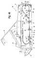
- FIG. 1is a perspective view of the ballot marking terminal invention constructed in accordance with the invention showing the terminal in an operating position.
- FIG. 2is a perspective view of the ballot marking terminal of FIG. 1 showing the terminal in a closed position.
- FIG. 3is an enlarged perspective view of a remote user interface module for use with the ballot marking terminal of FIGS. 1 and 2 .
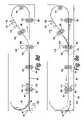
- FIG. 4 ais a simplified cross-sectional view of the ballot marking terminal of FIGS. 1 and 2 showing the terminal in its closed storage or transit condition.
- FIG. 4 bis a simplified cross-sectional view of the ballot marking terminal similar to FIG. 4 a showing the terminal in the process of being opened for use.
- FIG. 4 cis a simplified cross-sectional view of the ballot marking terminal similar to FIG. 4 a showing the terminal in an open operating condition.
- FIG. 4 dis a simplified cross-sectional view of the ballot marking terminal similar to FIG. 4 c showing principal paper guide components thereof removed to provide access to the paper path of the terminal.
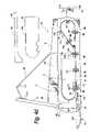
- FIG. 5is a perspective view of the ballot marking terminal of FIGS. 1 and 2 showing various alternative ballot feed trays provided for use with the terminal to accommodate ballots of various widths.
- FIG. 6is a top view of the ballot marking terminal of FIGS. 1 and 2 showing principal exterior housing features thereof.
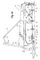
- FIG. 7is a top perspective view of the ballot marking terminal with the top section of the housing removed to show the principal interior components of the terminal.
- FIG. 8 ais a simplified cross-sectional view of the paper path of the ballot marking terminal of FIGS. 1 and 2 showing the receipt of a ballot by the terminal.
- FIG. 8 bis a simplified cross-sectional view of the paper path similar to FIG. 8 a showing the ballot having progressed in the terminal to a location just prior to printing.
- FIG. 8 cis a simplified cross-sectional view of the paper path similar to FIG. 8 a showing the ballot being presented on its back side as it passes the print head.
- FIG. 8 dis a simplified cross-sectional view of the paper path similar to FIG. 8 a showing the ballot at rest, having cleared the reversing loop of the paper path prior to being moved in the reverse direction.
- FIG. 8 eis a simplified cross-sectional view of the paper path similar to FIG. 8 a showing the ballot advancing along the reversing loop of the paper path prior to being printed on its front side.
- FIG. 8 fis a simplified cross-sectional view of the paper path similar to FIG. 8 a showing the ballot having stopped just prior to the print head.
- FIG. 8 gis a simplified cross-sectional view of the paper path similar to FIG. 8 a showing the ballot being printed on its front side as it passes the print head.
- FIG. 8 his a simplified cross-sectional view of the paper path similar to FIG. 8 a showing the ballot being discharged from the terminal.
- FIG. 8 iis a simplified cross-sectional view of the paper path similar to FIG. 8 a showing the ballot wherein the length of the ballot exceeds the length of the paper path along the ballot reversing loop and a pressure roller is raised to allow the leading edge of the ballot to overlap the trailing edge of the ballot.
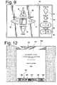
- FIG. 9is an enlarged front elevational view of the user interface keyboard of the ballot marking terminal.
- FIG. 10is a depiction of a typical initial display screen presented to the user prior to insertion of a ballot into the ballot marking terminal for marking.
- FIG. 11is a depiction of a subsequent display screen presented to the user to enable the user to select a language in which subsequent prompts are to be presented.
- FIG. 12is a depiction of a display screen which appears after display screen of FIG. 11 showing the details of the election.
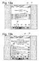
- FIG. 13 ais a depiction of a subsequent display screen showing a contest wherein a single candidate is to be selected.
- FIG. 13 bis a depiction of the display screen of FIG. 13 a following actuation of the zoom function.
- FIG. 14is a depiction of a subsequent typical display screen showing a contest wherein one of the candidates has been selected by the user.
- FIG. 15 ais a depiction of a display screen of a contest wherein two candidates are to be selected.
- FIG. 15 bis a depiction of a display screen similar to FIG. 15 a wherein two candidates have been selected.
- FIG. 16 ais a depiction of a display screen wherein a pop-up display has appeared to enable selection of a write-in candidate.
- FIG. 16 bis a depiction of a display screen similar to FIG. 16 a illustrating the entry of a write-in candidate.
- FIG. 16 cis a depiction of a display screen similar to FIG. 15 b showing the contest following the entry of a write-in candidate.
- FIG. 17is a depiction of a typical display screen showing a summary of selections previously made in individual contests of an election.
- FIG. 18is a depiction of a typical display screen which occurs following the return to an individual contest from the summary screen of FIG. 17 .
- FIG. 19is a depiction of a typical display screen utilized to provide an indication to a voter that the ballot marking terminal is currently marking his or her ballot.
- FIG. 20is a depiction of a typical display screen providing an indication to a voter that the ballot has been marked and is being returned to the user.
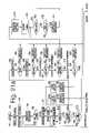
- FIGS. 21 a – 21 cshow a simplified functional block diagram of the operation of the principal systems and subsystems of the ballot marking terminal of FIGS. 1 and 2 .
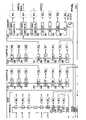
- FIGS. 22 a – 22 cshow a simplified flowchart of the steps taken by the voter in utilizing visual and aural prompts provided by the ballot marking terminal to make selections from the contests on the ballot.
- FIG. 23shows a typical pre-printed ballot for marking by the ballot marking terminal of FIGS. 1 and 2 .
- FIG. 24is a simplified block diagram showing the principal circuits and components of the ballot marking terminal of FIGS. 1 and 2 .
- a ballot marking terminal 30is seen to include a generally rectangular housing 31 having a pair of opposed handle portions 32 to facilitate placing the terminal in an operating position on a table or other support surface (not shown).
- the front face of the terminal housing 31includes on its right side a sloped voter interface panel 33 and a vertically disposed interconnect panel 34 .
- Housing 31further includes on the left side of its front surface a sloped panel 35 which includes an access door 36 for providing access to a memory card (not shown) in FIG. 1 installed within the terminal to provide data regarding the style or format of ballots to be received and processed by the terminal.
- the transparent window 37 in access door 36enables the access card to be viewed from the exterior of the terminal so that installation of the proper access card can be readily confirmed.
- a key lock 38 in the access doorprevents unauthorized access to the data card.
- a three-position key switch 39is provided on a vertical left side panel of housing 31 to enable the operating mode of ballot marking terminal 30 to be set.
- This key switchincludes OFF, ON and TEST positions which can be selected by officials at the polling place and which the ballot marking terminal is being used.
- An LED status light 40 above key switch 39indicates the powered-up status of the terminal. In a preferred embodiment, this light displays a steady green to indicate operation on an AC line power with a fully charged battery, or a blinking green to indicate operation on the AC line with an inadequately charged battery. During battery operation, the LED status light displays a steady amber with the battery adequately charged, or a blinking amber with the battery inadequately charged.
- a power switch (not shown) on the rear panel of housing 31provides a positive disconnect of all power from the terminal.
- housing 31includes at its front end a ballot tray 44 which communicates with a ballot receiving slot 45 ( FIG. 1 ) in the housing.
- Ballot receiving tray 44is pivotally mounted to housing 31 such that it may be pivoted from its operating position shown in FIG. 1 , to a closed position shown in FIG. 2 .
- a suitably dimensioned recess 46is provided in the front face of housing 31 to enable the ballot feed tray 44 to be pivoted to the closed position and to provide for a longer tray surface when the tray is in its operating position.
- ballot marking terminal 30includes an LCD touch screen assembly 47 which is pivotally mounted to housing 31 such that the display can pivot from a closed position in a recess 48 provided in the top surface of the housing to a generally vertical operating position as shown in FIG. 1 .
- a cover 49 pivotally mounted to housing 31 along its rear edgeengages the rear surface of display assembly 47 to support the display assembly in its operating position as shown in FIG. 1 , and pivots over recess 48 to cover display assembly 47 when the display assembly is stored in recess 48 , as shown in FIG. 2 .
- ballot feed tray 44is preferably pivoted into recess 46 prior to cover 49 being pivoted downwardly over display assembly 47 .
- Cover 49is dimensioned to extend over the top edge of feed tray 44 so that when cover 49 is in its closed position, feed tray 44 is effectively locked in its closed position.
- a pair of slide latches 50may be provided on the top surface of housing 31 to lock cover 49 closed for transit.
- one or more latch assembliesmay be provided on the outer surfaces (when closed as in FIG. 2 ) of ballot feed tray 44 and cover 49 to lock two members together, thereby security the members for transit.
- An audio interface with the voteris provided by a pair of headphones 51 which plug into one of two audio jacks 52 and 53 ( FIG. 2 ) on the front right surface of housing 31 .
- Audio jack 52is preferably a one-eighth inch jack and audio jack 53 is preferably a one-quarter inch jack.
- An additional jack 54is provided for connection to a remote voter interface module such as shown in FIG. 3 .
- An additional ADA jack 55provides for connection to a two-contact “sip and puff” device.
- a remote voter interface module 60may be optionally provided to permit voters to perform functions provided by voter interface keypad 33 while seated at a remote location, such as in a wheelchair.
- the moduleincludes a clamp assembly 61 which may include pivoting features to permit the module to be mounted to a supporting surface, such as, for example, the arm of a wheelchair.
- a pair of audio jacks 62 and 63provide standard one-eighth inch and one-fourth inch connections for headphones and an ADA jack 64 provides for connection to a conventional two-contact “sip and puff” device in the manner of jack 34 .
- a keypad 65 on module 60provides the same key switch inputs as are provided on keypad 33 .
- a pair of arrow-shaped UP and DOWN keys 66 and 67provide for up and down navigation, respectively, on the display screen of display assembly 47 or within a complementary audio menu.
- a pair of arrow-shaped keys 68 and 69provide for back (BACK) and forward (NEXT) navigation, respectively, on the display screen of display assembly 47 or in the conforming audio menu.
- a SELECT key 70provides for selection of a particular choice on the display screen or the audio menu.
- a diamond-shaped SCREEN blanking key 71enables the voter to selectively disable, or blank the display screen of display assembly 47 for improved privacy when voting using the audio interface.
- a round REPEAT key 72enables the voter to request that a name or phrase provided by the audio interface be selectively repeated.
- a rocker-type VOLUME switch 73enables the audio level of the audio interface to be selectively increased or decreased, and a rocker-type TEMPO key 74 enables the voter to selectively increase or decrease the rate at which synthesized audio is provided by the audio interface. Both of these functions return to nominal settings upon the insertion of a ballot so that each subsequent user can make his or her own adjustment from a fixed nominal setting.
- Module 60is preferably connected to terminal 30 by a flexible cable 75 , although it is contemplated a wireless RF or JR link could be used instead.
- interface panel 33An identical set of voter interface key switches is provided on interface panel 33 .
- interface panel 33includes arrow-shaped UP and DOWN navigation keys 76 and 77 , arrow-shaped BACK and FORWARD navigation keys 78 and 79 , respectively, and a square-shaped, centrally located SELECT key 80 .
- These keyshave the same functions in the audio interface protocol as the previously described navigation keys 66 – 70 of interface module 60 .
- voter interface panel 33includes a diamond-shaped SCREEN display blanking key 81 , a round REPEAT key 82 , and rocker-type VOLUME and TEMPO keys 83 and 84 , respectively.
- FIGS. 4 a – 4 dThe relationship between display assembly 47 , ballot tray 44 and housing 31 is shown in FIGS. 4 a – 4 d .
- ballot marking terminal 30shown in a closed or transit state with ballot tray 44 and cover 49 in their closed positions.
- Display assembly 47is protected within recess 48 by cover 49 .
- FIG. 4 aAlso shown in FIG. 4 a is the paper path through which ballot 43 is conveyed when inserted into ballot marking terminal 30 .
- This paper pathwhich is generally designated 85 , is formed by a bottom tray assembly 86 and a removable top tray member 87 , a ballot reversing guide assembly 88 , a removable rear-mounted guide assembly 89 , and a second removable guide member 90 at the bottom of recess 48 , and a fixed guide member 91 forming part of housing 31 .
- a conventional photo detector 92When a ballot is introduced through ballot receiving slot 45 , the leading edge of the ballot is sensed by a conventional photo detector 92 .
- drive roller 97may be alternatively powered by a separate motor in a reverse direction, i.e., in a direction tending to discharge the ballot, for a very brief moment as the leading edge of the ballot engages the roller. This technique provides for a better alignment of the ballot as it reaches print head 101 .
- ballot feed rollers 93 – 98stop, and a series of screens is presented to the viewer on the display screen module 47 or by the audio menu controlled by voter interface key switch panel 33 to enable the voter to make his or her choices of the candidates contained on the ballot.
- feed rollers 96 , 97 and 98are again powered to advance the ballot past print head 101 so that any necessary marking to the back side of the ballot can be accomplished.
- ballot feed rollers 93 – 95are caused to turn in a reverse direction so that, as the ballot again comes back into contact with tray assembly 86 , the ballot is conveyed back in the direction of ballot feed slot 45 .
- a solenoid operated gate 102is actuated to divert the ballot upwardly away from the ballot feed slot and around the path defined between guide members 87 , 91 and 90 .
- the ballotdoes not extend out onto the feed tray but rather is entirely contained within housing 31 .
- ballot feed rollers 93 – 95are stopped.
- ballot feed rollers 93 – 95 and ballot feed rollers 96 – 98are caused to rotate in a forward direction so as to again advance the ballot along tray assembly 86 toward print head 101 .
- Feed rollers 96 – 98now advance the ballot past print head 101 to cause the front side to be printed and ballot feed rollers 93 – 95 are reversed to receive the printed ballot and convey the ballot back to the voter through feed slot 45 .
- Pinch rollers 104 – 109are provided in opposition to ballot drive rollers 93 – 98 at the opposite side of paper path 85 to force a frictional engagement between the drive rollers and the ballot.
- the leading edge of the ballotmay overlap the trailing edge of the ballot as the ballot is conveyed by ballot feed rollers 96 – 98 past print head 101 .
- a solenoid 110is provided to lift roller 106 out of engagement with roller 95 . This prevents roller 95 from having any effect on the overlapping ballot while the overlap exits.
- the solenoid-actuated ballot diverter gate 102is positioned to allow the ballot to feed out through ballot receiving slot 45 .
- ballot position detector 103can be eliminated by timing the actuation of the ballot drive rollers after the trailing edge of the ballot has cleared ballot position sensor 100 .
- An additional function performed within the ballot marking terminal 30is the scanning of both sides of the ballot as the ballot is received. This is accomplished by a pair of scanners 111 and 112 as the ballot proceeds along feed tray 86 . As will be described presently, the information derived from scanners 111 and 112 is utilized in the operation of print head 101 to mark selections on the ballot. Also, this information is analyzed to determine whether the ballot has been damaged, what format of ballot has been inserted and whether any marking has already occurred of the ballot. A third scanner 113 positioned along ballot feed path 85 is utilized to determine whether print head 101 has properly marked a ballot. In particular, the data derived by scanner 113 is utilized to determine whether any selection positions on the ballot which should have been marked have been marked, or whether any selection locations that should not have been marked have been marked.
- conversion of ballot marking terminal 30 from a storage or transit condition to an operating conditionis first accomplished by pivoting cover 49 upwardly away from recess 48 and then pivoting display assembly 47 forward toward the front of the unit.
- feed tray 44is pivoting downwardly as shown in FIG. 4 c when display assembly 47 has been pivoted to its viewing position, cover 49 is pivoted forward until the front edge of the cover engages a selected one of a plurality of ridges 114 on the rear surface of the assembly.
- Cover 49preferably includes a latch engaging member 115 for engaging the sliding latch 50 when the cover is in its storage position as shown in FIG. 4 a .
- ballot guide assemblies 87 , 89 and 90are preferably constructed as removable components to provide access to paper path 85 in the event a ballot becomes jammed or cleaning of the paper path 85 is necessary.
- guide member 89is removable from the back side of housing 31 and may include a pair of additional rollers 116 and 117 to reduce friction with the ballot as it reverses direction prior to encountering print head 107 .
- ballot guide assemblies 87 and 90are removable through recess 48 , cover 49 first being pivotally positioned toward the rear of housing 31 and then guide member 90 being lifted out through recess 48 .
- a latch assembly(not shown) may be optionally provided to secure ballot guide member 90 in position and a handle 118 may be molded into the guide member to assist in the removal process.
- ballot guide member 87can be similarly removed through recess 48 .
- a handle 119may be provided on the top surface of guide member 87 to assist in the removal.
- a latch assemblymay be provided to hold ballot guide member 87 in position within housing 31 .
- Ballot feed tray assembly 86 and ballot guide members 87 , 88 , 89 , 90 and 91may be advantageously molded of a high-strength, durable plastic material.
- the surfaces of these members which engage the ballotmay be provided with a plurality of parallel-spaced ribs to minimize contact with the face of the ballot and thereby minimize friction between the ballot and the housing and the ballot advances along paper path 85 .
- ballot tray assembly 44is preferably constructed to accommodate feed tray members of various widths.
- ballot feed tray 44preferably consists of a base member 120 on which tray surface members 121 – 124 of progressive increasing widths are mounted.
- the tray surfacesare each preferably secured to the tray base 120 by means of a pair of machine screws which extend through apertures and engage the tray member by means of threaded bores 125 and 126 .
- FIG. 5As can be seen in FIG.
- each of the feed tray members 121 – 124define ballot feed paths of appropriate widths to encourage the ballot to be correctly fed through ballot feed slot 45 .
- a shutter assembly 127comprising a pair of spring-biased shutters may be provided to mask ballot feed slot 45 on either side of the desired ballot feed channel.
- this assembly 127may have first and second shutters 128 and 129 disposed on either side of the ballot feed channel and constrained to freely swing outwardly but not inwardly, so that a ballot being discharged that is not perfectly aligned with the feed channel is freely discharged onto a feed tray, while a voter attempting to feed the ballot in misalignment with the feed slot is prevented from doing so by the shutters.
- the shutter assembly 127may be mounted to the front of housing 31 by means of a pair of machine screws 130 and 131 so that the shutter assembly 127 can be readily changed to accommodate different ballot widths.
- ballot marking terminal 30may include a combination battery access and print head access door 132 .
- a key lock assembly 133may be provided to prevent unauthorized access to either the print head or the battery.
- FIG. 7Paper path 85 and certain principal components of ballot marking terminal 30 are shown in FIG. 7 , which depicts the terminal with the top section of the housing and ballot guide members 87 , 89 and 90 removed. A plurality of parallel-spaced ribs are shown to be provided on the ballot engaging surface of tray assembly 86 to minimize function with the ballot. The need for guide rails is avoided by the use of ballot feed trays appropriate to the ballot width. Additional components seen FIG. 7 include a receptacle 135 for receiving AC power, a power supply module 136 , a key switch interface module 137 and a processor assembly 138 .
- FIGS. 8 a – 8 eThe handling of ballot 43 within ballot marking terminal 30 is illustrated in FIGS. 8 a – 8 e .
- detector 92senses the leading edge of the ballot and ballot feed rollers 93 – 95 and 96 – 98 are caused to rotate, feeding the ballot as shown from ballot feed slot 45 .
- the ballotcontinues to advance until the leading edge of the ballot is sensed by sensor 100 , at which time ballot feed rollers 93 – 95 and 96 – 98 are stopped, positioning the ballot at shown in FIG. 8 b .
- the voteris now presented with a series of screens on the LCD touch screen assembly 47 to provide the voter with the opportunity to make a selection in each contest contained on the ballot.
- both the top and bottom surfaces of the ballothave been scanned by scanners 111 and 112 to form a bitmap within the terminal processor, and, in a manner to be described, the bitmap is processed to determine the I.D. of the ballot and the exact location of each marking location contained on the ballot.
- the ballotcontinues to move in the reverse direction along paper path 85 until its trailing edge clears sensor 103 , at which time the ballot stops as shown in FIG. 8 d .
- the solenoid-actuated ballot diverter gate 102has been actuated so that ballot 43 does not protrude through ballot feed slot 45 and therefore becomes accessible to the voter.
- Ballot 43is next advanced toward print head 101 as shown in FIG. 8 e until reaching the position shown in FIG. 8 f
- Print head 101next prints the top side of the ballot as the ballot continues past the print head as shown in FIG. 8 g .
- the solenoid-actuated ballot diverter gate 102is not actuated, and the ballot is caused to be discharged through ballot receiving slot 45 .
- the votercan then take ballot 43 , marked on both sides in accordance with his selections, to a scanner or ballot box (not shown) for deposit and subsequent tabulation.
- a scanner or ballot boxnot shown
- the shutter assembly 127 at ballot feed slot 45pivots outwardly as necessary to allow the ballot to pass in the event the ballot is not precisely aligned with the installed ballot feed tray.
- solenoid 110is actuated to lift pressure roller 106 clear of the paper path, as shown in FIG. 8 i .
- the leading edge of the ballotcan freely pass over the trailing edge, and ballot feed roller 95 , although operating, has no effect on the progress of the ballot.
- This featureallows the ballot reversal loop to be shorter than would otherwise be necessary to handle a long ballot, thereby reducing the necessary depth of housing 31 .
- the user interface key switch panel 33is advantageously formed from a seamless flexible plastic membrane for easy maintenance and cleaning. Keys are preferably recessed and are of a positive-action such that the user is provided tactile feedback that his actuation of a switch has occurred. Furthermore, raised rims are preferably provided around each key to make the shapes more easily discerned by touch. The entire switch assembly is preferably removable from housing 31 so that alternative keyboard arrangements can be readily provided if desired.
- an introductory screenis preferably displayed on the LCD screen 141 provided by display assembly 47 .
- This introductory displaymay be customized in accordance with the requirements of the election jurisdiction utilizing the ballot marking terminal.
- the screenis configured to prompt the voter to insert his unmarked pre-printed ballot into the terminal.
- a screen 142 shown in FIG. 11the voter is next prompted by a screen 142 shown in FIG. 11 to select a language in which he desires to receive assistance in marking his ballot.
- a languagein which he desires to receive assistance in marking his ballot.
- two languagesEnglish and Spanish
- the next screen 143shown in FIG. 12 , is displayed.
- screen 142like many subsequent screens, provides a function bar 144 a means by which a voter can perform certain functions.
- a zoom functionis provided at 145 by which the display is increased in size. The first actuation of the zoom icon enlarges the display and a second actuation returns the display to its normal size.
- function bar 144Another function provided on function bar 144 is a high contrast function 146 which causes the color display on the LCD screen to change to a monochrome high contrast display for those voters having difficulty reading the screen because of an inability to discern colors. Also provided on function bar 144 is an exit function 147 which causes the selection process to be terminated and the unmarked ballot to be return to the voter through feed slot 45 . In practice, this function may be provided with a pop-up screen forcing the voter to confirm his decision to terminate the selection process prior to the selection process actually terminated and the ballot being returned.
- ballot marking terminal 30provides with screen 143 a confirmation to the voter, in the language previously selected, as to which ballot he or she is making selections for, together with any necessary voting instructions.
- the ballot styleis indicated as ABC, and the election is identified as the Consolidated Election for Apr. 1, 2003.
- the function barhas been expanded to include a BACK designation 148 and a NEXT designation 149 .
- the BACK designation 148enables the voter to return to the previously displayed screen 142 , perhaps to make a different language selection.
- the NEXT designation 149enables the viewer to proceed to the next screen after reading the message conveyed by screen by 143 .
- the banner strip 150 at the top of screen 143 and subsequent screensremains constant during the election process and may be utilized by the election jurisdiction to present a seal or other identification of the jurisdiction to the voter.
- FIGS. 13 a and 13 bshow screens which might be displayed for an election contest having three named candidates and a single write-in candidate, wherein the voter is allowed to vote for a single candidate.
- screen 151the four possible selections are contained within a box 152 , each candidate being within a section 153 of the box and having an associated oval 154 which is darkened or filled in to indicate selection of the candidate. Selections are made on touch screen 141 by touching the section 153 or oral 154 associated with the selected candidate or write-in, which causes that particular section 153 to change color and the associated oval to be changed to black.
- SCROLL functionwill be provided consisting of UP or DOWN arrows on either side of box 152 to prompt the voter that additional candidates are available for that contest. In some jurisdictions it may be necessary that a voter scroll through the entire list before having access to the next function 149 .
- FIG. 13 billustrates the ZOOM function.
- screen 151changes to screen 155 , making the selection of a candidate easier for a voter having a sight impairment.
- To return from screen 155 to screen 151it is only necessary for the voter to touch the ZOOM icon 145 again.
- FIG. 14illustrates the screen 156 that appears after the voter has touched the section 153 associated with Richard Nixon/Spiro Agnew. As seen, section 153 A is highlighted and the oval 154 A is marked. It is possible to make the same selections utilizing the navigation keys in user interface key switch panel 33 .
- the UP and DOWN keys 76 and 77respectively ( FIG. 9 ), allow the voter to scroll through sections 153 A– 153 D, the selected sections 153 A– 153 D being successfully highlighted. To make a selection, it is necessary for the voter to depress the SELECT key 80 for a highlighted section, after which the associated oval 154 is marked and the selection is recognized.
- the UP and DOWN keysalso allow the voter to scroll through the functions of function bar 155 , except for the NEXT and BACK functions, which are accessed through BACK and NEXT keys 78 and 79 of user interface panel 33 .
- a contest where two candidates are to be selectedutilizes a screen similar to 156 .
- two selectionscan be made in the manner previously described for FIG. 14 .
- a promptwill appear in the form of a pop-up instructing the voter that he must first deselect one of the candidates he has previously selected.
- To deselect a candidateit is only necessary for the touch screen user to touch one of the previously selected candidates, causing that candidate to be deselected after which he is free to make another selection.
- the interface keyboard usercan scroll to a newly selected candidate and against depress SELECT key 80 to select that candidate.
- a voter utilizing the ADA “sip and puff” interfacescrolls through the candidate selections and function bar icons in one direction and in a closed loop. The voter continues scrolling through the function selections of function bar 144 until reaching the first candidate on the list, at which time he or she reaches the candidate to be deselected.
- the “sip and puff” interfaceis then used to select that candidate for deactivation and the uni-directional scrolling is continued until the newly selected candidate is in position for selection.
- the “sip and puff” interface userthen scrolls to the NEXT function icon and actuates select.
- the screenappears as shown in FIG. 15 b , the screen 158 showing two candidates highlighted and selected.
- the votertouches a write-in section 153 D. With section 153 D then highlighted, the associated oval 154 D is not marked. For voters using keypad 33 , or keypad 65 , it is necessary to scroll to write-in section 153 D, and then SELECT. After a short time delay, a pop-up display in the form of a keyboard 159 appears as shown by screen 160 . The voter next selects the letters of the write-in candidate's name, one letter at a time, until the entire name appears on display 160 , as shown in FIG. 16 b .
- the voterWhen the voter has completed typing in the name of the desired write-in candidate, he or she touches the done space, causing the pop-up to disappear after a short delay and the write-in candidate's name to appear in the previously selected write-in section 153 D ( FIG. 16 c ).
- the associated oval 154 Dis preferably marked so that the voter has successfully selected the write-in candidate.
- the NEXT icon 149now flashes, prompting the voter to continue to the next contest. It should be noted that, while the write-in process is occurring, the NEXT function is not available.
- the ZOOM, HIGH CONTRAST and EXIT functionsremain available, as does the BACK function 148 which allows the voter to abandon the write-in process and return to the contest selections shown on screen 161 in FIG. 16 c . It should be noted that, once the voter has returned to the contest and both permitted selections have been made, the NEXT icon 149 flashes to prompt the voter to move on to the next contest.
- a pop-up screenmay appear alerting the user to that fact. It then remains for the user to indicate or confirm on that pop-up display that it is his or her intention to vote for a lesser number of candidates than permitted by the contest. In those situations where such a prompt is used for under-voting, the NEXT icon 149 does not appear until the prompt has been confirmed.
- a pop-up promptappears notifying the voter of the attempt to over-vote and indicating to him or her that a previously selected candidate must first be deselected before another candidate can be selected.
- This over-vote promptmay disappear after a short time period allowing the voter to deselect a previously selected candidate or actuate the NEXT icon 149 to move on to the next contest.
- the selection processadvances to a summary screen 162 , as shown in FIG. 17 .
- the summary screenincludes a summary box for each contest, the selections for that contest being displayed in the box.
- Summary box 163 for the contest depicted in FIGS. 13 a and 13 bshows the voter's selection for that contest.
- Summary box 164 for the contest depicted in FIGS. 15 a , 15 b and 16 a – 16 cshows the voter's selections for that contest.
- the votercan accept his selections for the two contests by touching the MARK BALLOT function 165 provided in screen 162 of FIG. 17 and his previously inserted ballot will be marked in accordance with his selections and then returned to him through ballot feed slot 45 .
- the votercan be prompted to advance to a confirmation screen and then prompted to confirm that he wants his ballot to be printed in compliance with his selections.
- the BACK function 148 and the NEXT function 149are not available since the voter can only return to his or her previous selection by touching the appropriate summary box. For example, by touching box 164 the voter is returned to screen 161 ( FIG. 18 ) where his or her previously entered selections remain displayed. He or she may then change these selections in the manner previously described or, in the event they are satisfactory to the voter, he or she may touch the BACK TO REVIEW icon 166 to return to the selection summary screen 162 . It should be noted that the BACK function 148 and NEXT function 149 are not available on this screen 161 since the only action available to the voter is to return to summary screen 162 .
- a screen 167is displayed to indicate to the voter that the printing process is occurring.
- this screenincludes a progress bar 168 to indicate the time remaining before the ballot is returned to the voter. None of the functions provided by function bar 144 are available on screen 167 .
- the ballot marked indicationmay be provided on a screen 169 , as shown in FIG. 20 , prompting the voter to remove the ballot from the ballot tray 44 and take the machine-marked ballot to the scanner or ballot box for subsequent tabulation.
- the display screen 151reverts to the introduction screen 143 shown in FIG. 12 .
- ballot marking terminal 30may be understood by reference to the simplified flowchart shown in FIGS. 21 a – 21 c .
- a pre-programmed compact flash card 170is installed in a socket 171 ( FIG. 7 ) to provide information on the layout of each ballot style to be processed by the ballot marking terminal.
- the compact flash data cardis read at 173 and the appropriate ballot information required for processing the ballot styles to be input to the terminal is loaded into RAM within the computer module 138 at 174 .
- the screen 140 depicted in FIG. 10is now displayed at 175 pending insertion of a ballot.
- the ballotUpon insertion of a ballot at 176 , the ballot is caused to pass between scanners 111 and 112 at 177 and then data derived from the scan is stored in a bitmap.
- a timer functionis started at 178 and an analysis is made of the scanned image for damage or folding at 180 , and in the event damage is detected at 181 , further movement of the ballot is stopped at 182 , a message is displayed at 183 , and the ballot is returned to the voter at 184 .
- a messageis displayed at 186 on the LCD display screen 141 to instruct the voter to remove the ballot.
- a timer functionis started at 187 and, in the event that the ballot has not been removed by the voter at 188 and the time has elapsed at 189 , a further message is displayed at 190 and an alarm is sounded at 191 .
- the message displayed at 175reappears, and the ballot marking terminal 30 is available to process another ballot.
- the ballot I.D.is read from the bitmap generated by scanners 111 and 112 at 200 .
- the I.D.is checked for validity at 201 to determine whether the ballot style is valid for the particular polling place in which ballot marking terminal 30 has been installed. If the ballot I.D. is not valid, a message is displayed at 202 and the ballot is ejected in the manner previously described at 184 . If the ballot I.D. is valid, then the bitmap data is checked to determine whether the ballot is damaged or otherwise not complete at 203 . If the ballot is determined to be damaged at 204 , then a message is displayed to this effect at 205 and the ballot is ejected from the terminal at 184 in the manner previously described. If the ballot is found to not be damaged at 204 , then print alignment is checked at 206 and found to be outside of acceptable limits at 207 , the message is displayed at 208 and the ballot is ejected from the terminal at 184 in the manner previously described.
- ballot alignmentis within limits at 207 , then the ballot is checked for selections having been marked, i.e., ovals filled in, at 210 . If the ballot is found to be marked at 211 , then a message is displayed to this effect at 212 and the ballot marking terminal 30 reverts to a summary routine 213 . During this summary routine, markings existing on the ballot are read and the corresponding selections are displayed to the voter on a screen similar to screen 162 depicted in FIG. 17 , with the exception that the marked ballot function 165 is not provided and instead a return ballot function (not shown) is displayed instead. At the same time, a timer is started at 214 .
- the ballotis ejected at 184 in the manner previously described.
- a messageis displayed at 217 and the ballot is ejected at 184 as previously described.
- the ballot lengthis calculated from the scanned image at 218 and the length is found to not be within allowable limits at 219 , then a message is displayed at 220 and the ballot is ejected at 184 in the manner previously described.
- a messageis displayed at 221 ( FIG. 21 b ) and the voter selection routine is begun at 222 .
- a timeris started at 223 .
- the selection summary routineis initiated at 227 .
- a timeris started at 228 . If the summary has not been accepted by the voter at 230 , and the time allocated for the voter reviewing the summary has elapsed at 231 , then a message is displayed at 232 advising the voter that his review time has elapsed and the ballot is ejected from the terminal 184 in the manner previously described.
- the voterhas approved the summary at 230 , then a determination is made whether the ballot is two-sided, i.e., printed on both the front and back sides, at 233 .
- a timeris started at 234 , and the front side of the ballot is positioned in front of the print head at 235 by actuation of the ballot transport mechanism within the terminal. If the ballot has been inserted front side up, then the ballot must be first advanced around the ballot reversing loop and then back to the print head. When the ballot has been properly positioned, the front of the ballot is printed by the printer at 236 as the ballot is caused to pass beneath the print head 101 . At the same time, print verification scanner 113 is caused to verify operation of the printer at 237 as the ballot continues past the printer along paper path 85 .
- a timeris started at 250
- a print cycle for printing the bottom side of the ballotis started at 251
- a print verify routineis started at 252 .
- movement of the ballotis stopped at 239 and a message is displayed at 240 in the manner previously described.
- a messageis displayed at 256 to alert the voter to a terminal malfunction and an alarm is sounded at 191 in the manner previously described.
- the print cycleis determined complete at 254 , then a timer is started at 257 , and the ballot is positioned at 258 to be in position for the starting of the print cycle 236 which prints the front side of the ballot.
- This print cycle and the concurrent validation at 237continues in the manner previously described for a single-sided ballot.
- the ballotis inserted inverted, i.e., front side down, then the print head prints the front side of the ballot on the first pass, and the back side of the ballot on the second pass.
- the ballotcan be advanced around the reversing loop a third time so that the ballot will be ejected front side up.
- ballot marking terminal 30functions to receive a pre-printed unmarked ballot, identify the ballot, and by reference to data stored on a compact flash data card installed in the terminal, to present a series of screens or audio prompts to a voter to enable the voter to make selections which are presented in summary form to the voter, and if approved, appropriately marked on the ballot.
- the ballotis then returned to the voter to deposit in a scanner or ballot box for subsequent tabulation. No record of the voter's selections is maintained in the terminal 30 .
- Ballot marking terminal 30is capable of processing a variety of ballots of different lengths and widths. Furthermore, such ballots may have a variety of formats for identifying their particular style or layout for purposes of the terminal knowing which contests are presented on the ballot. Referring to FIG. 23 , one ballot style 260 may be identified, for example, by a bar code 261 provided on the trailing edge of the ballot. In accordance with conventional practice, ballot style 260 may also incorporate sync marks 262 along one or both edges to assist in identifying the location of candidate marking spaces.
- the ballot marking terminal 30provides interfaces by which a voter can make selections on a pre-printed paper ballot using either a touch screen visual interface, and audio keyboard interface or a two-contact audio or video “sip and puff” ADA interface.
- the three interfaceswork in a coordinated manner to allow selections to be marked in the most efficient manner possible by the voter.
- an initial messageis displayed at 260 , and the terminal automatically progresses to a language selection screen such as that shown in FIG. 11 .
- the voternow selects between languages, in this case, English or Spanish.
- the terminalproceeds, with the possible exception of intervening instruction pages, to the first contest.
- the voterWhen the voter is making his or her selections by means of a voter interface keypad 33 , the voter scrolls through the language selections, which are highlighted if the screen is activated, or which are only audio prompts if the screen is blank, until the desired language has been highlighted or the desired audio prompt has been spoken, at which time the voter depresses the select key 80 ( FIG. 9 ) and the selection is recognized. Subsequent instruction pages, if any, are presented in the selected language and contest number one is made available to the voter.
- the SEL functionsare contained within broken lines to indicate that they are only required in the event the keypad is utilized or the “sip and puff” interface is in use.
- the voterscrolls through the selections, in this case, English and Spanish, until the desired selection occurs. Scrolling is done in one direction only so that after the last selection has been scrolled to, the next scroll command brings the voter back to the first selection. This closed-loop scrolling is shown in dotted lines where applicable.
- contest number oneUsing the touch screen, the voter may directly select any one of the four candidates 263 – 266 , the NEXT function 267 , the HIGH CONTRAST function 268 , the ZOOM function 269 or the EXIT function 270 .
- the candidate's nameis touched on the touch screen, the candidate's name is framed in color and the associated oval is marked.
- the screenreverts to a write-in screen wherein the letters A through Y may be scrolled through as well as a space, finish and delete function.
- the NEXT functionWhen the NEXT function is selected, the screen displays contest number two.
- the screenWhen the HIGH CONTRAST function is selected, the screen reverts to a monochrome high contrast image until the high contrast function is actuated a second time. Similarly, when the ZOOM icon is selected, the display is enlarged until the ZOOM function is actuated again.
- a confirmation screentypically pops up and, if exit is confirmed, the ballot is returned at 271 to the voter.
- the voterScrolls up or down through selections 263 – 270 using the arrow-shaped UP and DOWN keys 76 and 77 .
- the candidates and functions thus selected by keypad scanningare highlighted as they are scanned, but are not selected.
- the displayhas been blanked by actuation of the SCREEN blank key 81 , then the high contrast and zoom functions are skipped in the scanning process and the voter relies on synthesized speech to identify each selection as he scrolls through the list of possible selections. Since the keypad allows the voter to scroll up or down, the selection process is not closed-loop. In the audio mode, when exit is selected, the confirmation audio prompt will follow which must be confirmed before the selection process will be terminated and the ballot returned.
- the votermay actuate the arrow-shaped NEXT key 79 at any time to proceed directly to the next contest.
- the BACK functionis not available to the voter in contest number one since this is the first contest in the series of contests to be presented to the voter.
- a visual and/or audio promptmay be presented and require confirmation to prevent inadvertent under-voting prior to proceeding to the next contest.
- attempts at over-votingare similarly followed by a visual or audio prompt, or both, to enable the voter to remedy the attempted over-vote.
- a similar logicapplies to the selection of a write-in candidate.
- the voterproceeds through the alphabet A–Z, space, finish, and delete. Using the touch screen, the voter need only touch the pop-up keyboard to enter the letters of the write-in candidate.
- the voterscrolls up and down, observing visual and/or audio prompts to make a selection using the select key 80 .
- Scrollingis done in one direction only so that, after the delete function, the next opportunity presented for selection is the A character.
- the finish functionis selected, the display reverts to the location of the write-in candidate and subsequent scrolling within contest number one takes place from there.
- Movement to the next letter in the candidate's nametakes place automatically with the selection of either a letter or space.
- Selection of the finish function 272returns the terminal to contest number one and selection of the exit function 273 , after confirmation of a subsequent pop-up confirmation display, terminates the selection process and causes the ballot to be returned to the voter at 271 .
- Selection of the second letter of the write-in candidate's nameis accomplished in the same manner as selection of the first character.
- the functions finish 274 , back 275 , and exit 276appear in the scrolling cycle.
- data entryis direct utilizing the touch screen keyboard and indirect, requiring actuation of the select key 80 utilizing the keypad voter interface and either video or audio prompts, using the keypad or ADA interfaces.
- the uni-directional scrollingrequires that the exit function be followed by a return to the letter A.
- the back function 275is available when selecting the second letter since a previous letter has been selected and may require change.
- the third letter of the write-in candidate's nameis selected in the same manner as the second letter, with finish function 277 ( FIG. 22 b ), the back function 278 and a exit function 279 being included in the scrolling process.
- a selectionis made available in contest number two.
- Three candidates, 280 – 282are available for selection, as well as NEXT function 283 , HIGH CONTRAST function 284 , ZOOM function 285 , BACK function 286 and EXIT function 287 . These functions are accessed in the manner previously described in connection with contest number one. BACK function 286 is available since a previous contest is now available to return to.
- the selection processproceeds to contest number three.
- This contestprovides three candidates 288 – 290 , a NEXT function 291 , a HIGH CONTRAST function 292 , a ZOOM function 293 , a BACK function 294 and an EXIT function 295 . Access to these functions is provided in the same manner as access to the functions in contest number two.
- the selection processprogresses to a summary screen wherein the selections previously made in contests one, two and three are displayed to the voter.
- the votercan directly select on touch screen 141 , or by means of keypad interface 33 , scroll through the various contest summaries 300 – 301 , and ACCEPT function 303 , a HIGH CONTRAST function 304 , a ZOOM function 305 and an EXIT function 306 .
- the voterselects this contest, either directly on touch screen 141 or through scrolling action by means of keypad interface 33 or “sip and puff” ADA interface 55 to cause the terminal to return to the contest so that the voter can makes changes if desired.
- the summary processdirects the terminal to contest number two ( FIG. 22 c ) wherein three candidates 280 – 282 are presented for selection along with a RETURN function 283 , a HIGH CONTRAST function 284 , a ZOOM function 285 and an EXIT function 286 .
- Selection within this contestis now done in the same manner as the previous selection, except that the NEXT function 283 is replaced with a RETURN function 307 which returns the voter to the summary page.
- the NEXT function 283 and the BACK function 286 of contest number twodo not appear as the voter is required to return to the summary page after making any necessary changes.
- Actuation of the EXIT function and subsequent confirmationcauses the selection process to be terminated, and the ballot to be returned to the voter at 271 .
- Execution of the RETURN function 307causes a return to the summary page with the contest number two selections 301 highlighted but not selected.
- Actuation of the ACCEPT function 303 within the summary pagecauses the ballot to be marked at 308 and a message to be conveyed to the voter at 309 that the ballot has been marked and is being returned at 271 .
- a confirmation pagemay be represented wherein the voter is requested to confirm his or her decision to mark the ballot prior to the ballot being marked by terminal 30 .
- ballot marking terminal 30employs a voter interface scheme that allows efficient voting utilizing touch screen 141 , keypad 33 or a two-contact “sip and puff” connection at ADA port 54 .
- ballot marking terminal 30the various functions of ballot marking terminal 30 are controlled by a main processor 138 , a peripheral controller and a hardware controller 321 .
- Processor 138communicates with peripheral controller 320 by means of an ISA bus 322 and a parallel audio connection.
- Processor 138communicates with the hardware controller 321 by means of a serial interface.
- Hardware controller 321is responsible for controlling for three paper path motors 323 , 324 and 325 and a carriage motor 326 which drives print head or pen 101 .
- Conventional motor drive circuits 327 , 328 , 329 and 330are provided to drive motors 323 , 324 , 325 and 326 , respectively.
- Hardware controller 321also receives inputs from the two paper position sensors 92 and 100 and a carriage home sensor 331 .
- Pen 101is actuated by convention pen drive electronics 332 in response to signals generated by hardware controller 321 .
- Peripheral controller 320receives inputs from scanners 111 , 112 and 113 and communicates with a switch interface board 333 by means of a serial I/O interface 334 .
- Switch interface board 333provides signals to the power supply/battery status LED 40 , an optional beep key actuation transducer 335 , keypad 33 and the remote keypad module 60 .
- Key switch 39also provides input to board 333 .
- a rechargeable battery pack 338 accessible through access door 132provides power to the switching power supply 337 .
- a battery gas gauge board 339provides LED bar graph display (not shown) on the rear panel of the terminal to provide an indication of battery condition when the terminal is in storage.
Landscapes
- Physics & Mathematics (AREA)
- General Physics & Mathematics (AREA)
- Time Recorders, Dirve Recorders, Access Control (AREA)
- Management, Administration, Business Operations System, And Electronic Commerce (AREA)
Abstract
Description
Claims (60)
Priority Applications (8)
| Application Number | Priority Date | Filing Date | Title |
|---|---|---|---|
| US10/733,112US7080779B2 (en) | 2002-07-26 | 2003-12-11 | Ballot marking system and apparatus |
| PCT/US2004/000826WO2004068418A2 (en) | 2003-01-17 | 2004-01-14 | Ballot marking system and apparatus |
| CA2513638ACA2513638C (en) | 2003-01-17 | 2004-01-14 | Ballot marking system and apparatus |
| EP04702143AEP1588331A4 (en) | 2003-01-17 | 2004-01-14 | Ballot marking system and apparatus |
| US10/976,210US7314171B2 (en) | 2002-07-26 | 2004-10-29 | Ballot marking system and apparatus having ballot alignment compensation |
| US10/976,226US7344071B2 (en) | 2002-07-26 | 2004-10-29 | Voting system and apparatus using voter selection card |
| US10/978,266US7314172B2 (en) | 2003-01-17 | 2004-11-01 | Ballot marking system and apparatus having periodic ballot alignment compensation |
| US11/024,076US7566006B2 (en) | 2002-07-26 | 2004-12-28 | Pre-printed document marking system and apparatus |
Applications Claiming Priority (5)
| Application Number | Priority Date | Filing Date | Title |
|---|---|---|---|
| US34891902P | 2002-07-26 | 2002-07-26 | |
| US10/347,528US7100828B2 (en) | 2002-07-26 | 2003-01-17 | Voting system utilizing hand and machine markable ballots |
| US10/454,276US7222787B2 (en) | 2002-07-26 | 2003-06-04 | Ballot marking system and apparatus utilizing single print head |
| US10/454,345US7753273B2 (en) | 2002-07-26 | 2003-06-04 | Ballot marking system and apparatus utilizing multiple key switch voter interface |
| US10/733,112US7080779B2 (en) | 2002-07-26 | 2003-12-11 | Ballot marking system and apparatus |
Related Parent Applications (2)
| Application Number | Title | Priority Date | Filing Date |
|---|---|---|---|
| US10/454,276Continuation-In-PartUS7222787B2 (en) | 2002-07-26 | 2003-06-04 | Ballot marking system and apparatus utilizing single print head |
| US10/454,345Continuation-In-PartUS7753273B2 (en) | 2002-07-26 | 2003-06-04 | Ballot marking system and apparatus utilizing multiple key switch voter interface |
Related Child Applications (4)
| Application Number | Title | Priority Date | Filing Date |
|---|---|---|---|
| US10/976,210Continuation-In-PartUS7314171B2 (en) | 2002-07-26 | 2004-10-29 | Ballot marking system and apparatus having ballot alignment compensation |
| US10/976,226Continuation-In-PartUS7344071B2 (en) | 2002-07-26 | 2004-10-29 | Voting system and apparatus using voter selection card |
| US10/978,266Continuation-In-PartUS7314172B2 (en) | 2003-01-17 | 2004-11-01 | Ballot marking system and apparatus having periodic ballot alignment compensation |
| US11/024,076ContinuationUS7566006B2 (en) | 2002-07-26 | 2004-12-28 | Pre-printed document marking system and apparatus |
Publications (2)
| Publication Number | Publication Date |
|---|---|
| US20040140357A1 US20040140357A1 (en) | 2004-07-22 |
| US7080779B2true US7080779B2 (en) | 2006-07-25 |
Family
ID=32829413
Family Applications (2)
| Application Number | Title | Priority Date | Filing Date |
|---|---|---|---|
| US10/733,112Expired - LifetimeUS7080779B2 (en) | 2002-07-26 | 2003-12-11 | Ballot marking system and apparatus |
| US11/024,076Expired - Fee RelatedUS7566006B2 (en) | 2002-07-26 | 2004-12-28 | Pre-printed document marking system and apparatus |
Family Applications After (1)
| Application Number | Title | Priority Date | Filing Date |
|---|---|---|---|
| US11/024,076Expired - Fee RelatedUS7566006B2 (en) | 2002-07-26 | 2004-12-28 | Pre-printed document marking system and apparatus |
Country Status (4)
| Country | Link |
|---|---|
| US (2) | US7080779B2 (en) |
| EP (1) | EP1588331A4 (en) |
| CA (1) | CA2513638C (en) |
| WO (1) | WO2004068418A2 (en) |
Cited By (18)
| Publication number | Priority date | Publication date | Assignee | Title |
|---|---|---|---|---|
| US20030034393A1 (en)* | 2000-11-20 | 2003-02-20 | Chung Kevin Kwong-Tai | Electronic voting apparatus, system and method |
| US20040046021A1 (en)* | 2000-11-20 | 2004-03-11 | Chung Kevin Kwong-Tai | Electronic voting apparatus, system and method |
| US20060041468A1 (en)* | 2000-12-28 | 2006-02-23 | Reardon David C | Custom printed, voter verified ballots with fixed range input |
| US20060169778A1 (en)* | 2000-11-20 | 2006-08-03 | Chung Kevin K | Electronic voting apparatus, system and method |
| US20060202031A1 (en)* | 2001-10-01 | 2006-09-14 | Chung Kevin K | Reader for an optically readable ballot |
| US20060255145A1 (en)* | 2001-10-01 | 2006-11-16 | Chung Kevin K | Method for reading an optically readable sheet |
| US20080121704A1 (en)* | 2002-07-26 | 2008-05-29 | Cummings Eugene M | Marking system and apparatus |
| US20080237342A1 (en)* | 2007-03-26 | 2008-10-02 | Runbeck Elections Services, Inc. | Acceptance tray for an election ballot printing system |
| US20080308634A1 (en)* | 2007-03-15 | 2008-12-18 | Steve Bolton | Integrated Voting System and Method for Accommodating Paper Ballots and Audio Ballots |
| US20090013111A1 (en)* | 2007-07-06 | 2009-01-08 | Es&S Automark, Llc | Unidirectional USB Port |
| US20090149153A1 (en)* | 2007-12-05 | 2009-06-11 | Apple Inc. | Method and system for prolonging emergency calls |
| US20090173778A1 (en)* | 2007-12-18 | 2009-07-09 | Cummings Eugene M | Ballot Marking Device Having Attached Ballot Box |
| US7635087B1 (en) | 2001-10-01 | 2009-12-22 | Avante International Technology, Inc. | Method for processing a machine readable ballot and ballot therefor |
| US8066184B2 (en) | 2008-04-30 | 2011-11-29 | Avante International Technology, Inc. | Optically readable marking sheet and reading apparatus and method therefor |
| US8261985B2 (en) | 2009-04-07 | 2012-09-11 | Avante Corporation Limited | Manual recount process using digitally imaged ballots |
| US8261986B2 (en) | 2009-10-21 | 2012-09-11 | Kevin Kwong-Tai Chung | System and method for decoding an optically readable markable sheet and markable sheet therefor |
| US10950078B2 (en) | 2018-07-27 | 2021-03-16 | Hart Intercivic, Inc. | Optical character recognition of voter selections for cast vote records |
| US11011005B2 (en) | 2019-01-24 | 2021-05-18 | Election Systems & Software, Llc | Systems and methods for preserving the anonymity of provisional ballots |
Families Citing this family (20)
| Publication number | Priority date | Publication date | Assignee | Title |
|---|---|---|---|---|
| US7344071B2 (en)* | 2002-07-26 | 2008-03-18 | Automark Technical Systems Llc | Voting system and apparatus using voter selection card |
| US7753273B2 (en) | 2002-07-26 | 2010-07-13 | Es&S Automark, Llc | Ballot marking system and apparatus utilizing multiple key switch voter interface |
| US7100828B2 (en)* | 2002-07-26 | 2006-09-05 | Automark Technical Systems, Llc | Voting system utilizing hand and machine markable ballots |
| US7163147B2 (en) | 2002-07-26 | 2007-01-16 | Automark Technical Systems, Llc | Ballot marking system and apparatus utilizing dual print heads |
| US7222787B2 (en) | 2002-07-26 | 2007-05-29 | Automark Technical Systems, Llc | Ballot marking system and apparatus utilizing single print head |
| US7314171B2 (en)* | 2002-07-26 | 2008-01-01 | Automark Technical Systems, Llc | Ballot marking system and apparatus having ballot alignment compensation |
| US7314172B2 (en)* | 2003-01-17 | 2008-01-01 | Automark Technical Systems, Llc | Ballot marking system and apparatus having periodic ballot alignment compensation |
| US8063885B2 (en)* | 2003-06-04 | 2011-11-22 | Es&S Automark, Llc | Ballot marking system and apparatus utilizing pivotal touchscreen |
| US7077314B2 (en)* | 2004-03-31 | 2006-07-18 | Oracle International Corporation | Methods and systems for voter-verified secure electronic voting |
| US6971574B1 (en)* | 2004-05-20 | 2005-12-06 | Herskowitz Irving L | Method of accurately verifying election results without the need for a recount |
| TWI251163B (en)* | 2004-10-29 | 2006-03-11 | Avision Inc | Apparatus and method for adjusting a digital setting value at a variable speed |
| US7464874B2 (en)* | 2005-02-24 | 2008-12-16 | Robert William Donner | Method and system for transparent and secure vote tabulation |
| US7387244B2 (en) | 2005-05-27 | 2008-06-17 | Election Systems & Software, Inc. | Electronic voting system and method with voter verifiable real-time audit log |
| US7878666B2 (en)* | 2005-06-30 | 2011-02-01 | Brother Kogyo Kabushiki Kaisha | Multi-function device with pivoting display |
| JP4359775B2 (en)* | 2005-06-30 | 2009-11-04 | ブラザー工業株式会社 | Image recording device |
| GB2428847A (en)* | 2005-08-02 | 2007-02-07 | James Knight | System for recording votes |
| US8358964B2 (en)* | 2007-04-25 | 2013-01-22 | Scantron Corporation | Methods and systems for collecting responses |
| US7768836B2 (en)* | 2008-10-10 | 2010-08-03 | Sandisk Corporation | Nonvolatile memory and method with reduced program verify by ignoring fastest and/or slowest programming bits |
| US8879085B2 (en)* | 2010-09-20 | 2014-11-04 | Ncr Corporation | Automatic print failure detection and correction |
| CA2823575C (en) | 2013-03-15 | 2016-03-15 | Election Systems & Software, Llc | System and method for decoding marks on a response sheet |
Citations (80)
| Publication number | Priority date | Publication date | Assignee | Title |
|---|---|---|---|---|
| US2940663A (en) | 1960-06-14 | Automatic vote-tallying machine | ||
| US3218439A (en) | 1964-08-07 | 1965-11-16 | Votronics Inc | Vote tallying machine |
| US3226018A (en) | 1965-12-28 | Ra/lsback | ||
| US3233826A (en) | 1966-02-08 | Voting machine | ||
| US3441714A (en) | 1965-07-09 | 1969-04-29 | Gen Res Inc | Computing and recording system |
| US3620587A (en) | 1969-12-18 | 1971-11-16 | Computer Electron Systems Inc | Portable self-contained voting booth |
| US3648022A (en) | 1969-10-20 | 1972-03-07 | Automatic Voting Machine Corp | Method for tabulating election returns |
| US3653587A (en) | 1970-01-26 | 1972-04-04 | Seymour B Hammond | Balloting system and apparatus therefor |
| US3722793A (en) | 1969-06-18 | 1973-03-27 | S Aronoff | Voting system |
| US3733469A (en) | 1971-09-15 | 1973-05-15 | P Meyer | Counting device for punch type ballot card |
| US4021780A (en) | 1975-09-24 | 1977-05-03 | Narey James O | Ballot tallying system including a digital programmable read only control memory, a digital ballot image memory and a digital totals memory |
| US4066871A (en) | 1976-11-18 | 1978-01-03 | Cason Sr Charles M | Voting system |
| US4236066A (en) | 1977-08-25 | 1980-11-25 | Wright Line Inc. | Voting machine |
| US4373134A (en) | 1981-05-06 | 1983-02-08 | Grace Phillip F | Magnetic card vote casting system |
| US4479194A (en) | 1982-08-10 | 1984-10-23 | Computer Election Systems | System and method for reading marks on a document |
| US4641240A (en) | 1984-05-18 | 1987-02-03 | R. F. Shoup Corporation | Electronic voting machine and system |
| US4649264A (en) | 1985-11-01 | 1987-03-10 | Carson Manufacturing Company, Inc. | Electronic voting machine |
| US4774665A (en) | 1986-04-24 | 1988-09-27 | Data Information Management Systems, Inc. | Electronic computerized vote-counting apparatus |
| US4807908A (en) | 1987-03-02 | 1989-02-28 | Business Records Corporation | Ballot for use in automatic tallying apparatus |
| US4813708A (en) | 1987-03-06 | 1989-03-21 | Business Records Corporation | Ballot for use in automatic tallying apparatus and method for producing ballot |
| US4981259A (en) | 1988-10-31 | 1991-01-01 | Ahmann John E | Ballot box |
| US5072999A (en) | 1989-10-27 | 1991-12-17 | Electronic Voting Systems, Inc. | Voting booth |
| US5189288A (en) | 1991-01-14 | 1993-02-23 | Texas Instruments Incorporated | Method and system for automated voting |
| US5213373A (en) | 1990-08-06 | 1993-05-25 | Severino Ramos | Mark position independent form and tallying method |
| US5218528A (en) | 1990-11-06 | 1993-06-08 | Advanced Technological Systems, Inc. | Automated voting system |
| US5248872A (en) | 1991-08-06 | 1993-09-28 | Business Records Corporation | Device for optically reading marked ballots using infrared and red emitters |
| US5278753A (en) | 1991-08-16 | 1994-01-11 | Graft Iii Charles V | Electronic voting system |
| US5377099A (en) | 1992-07-06 | 1994-12-27 | The Center For Political Public Relations, Inc. | Electronic voting system including election terminal apparatus |
| JPH07246732A (en) | 1994-03-10 | 1995-09-26 | Akiyoshi Saeki | Device for marking mark sheet |
| US5497318A (en) | 1992-07-20 | 1996-03-05 | Kabushiki Kaisha Toshiba | Election terminal apparatus |
| US5535118A (en) | 1995-02-22 | 1996-07-09 | Chumbley; Gregory R. | Data collection device |
| US5583329A (en) | 1994-08-01 | 1996-12-10 | Election Products, Inc. | Direct recording electronic voting machine and voting process |
| US5585612A (en) | 1995-03-20 | 1996-12-17 | Harp Enterprises, Inc. | Method and apparatus for voting |
| US5610383A (en) | 1996-04-26 | 1997-03-11 | Chumbley; Gregory R. | Device for collecting voting data |
| US5635726A (en) | 1995-10-19 | 1997-06-03 | Lucid Technologies Inc. | Electro-optical sensor for marks on a sheet |
| US5666765A (en) | 1995-06-20 | 1997-09-16 | Mark Voting Systems, Inc. | Suitcase voting booth with access for handicapped persons |
| US5758325A (en) | 1995-06-21 | 1998-05-26 | Mark Voting Systems, Inc. | Electronic voting system that automatically returns to proper operating state after power outage |
| US5764221A (en) | 1996-03-19 | 1998-06-09 | Willard Technologies, Inc. | Data collection system |
| US5821508A (en) | 1995-12-29 | 1998-10-13 | Votation, Llc | Audio ballot system |
| US5875432A (en) | 1994-08-05 | 1999-02-23 | Sehr; Richard Peter | Computerized voting information system having predefined content and voting templates |
| US5878399A (en) | 1996-08-12 | 1999-03-02 | Peralto; Ryan G. | Computerized voting system |
| US6078902A (en) | 1997-04-15 | 2000-06-20 | Nush-Marketing Management & Consultance | System for transaction over communication network |
| US6079624A (en) | 1997-12-08 | 2000-06-27 | William C. Apperson | Data processing form using a scanning apparatus |
| US6081793A (en) | 1997-12-30 | 2000-06-27 | International Business Machines Corporation | Method and system for secure computer moderated voting |
| US6134399A (en) | 1997-11-21 | 2000-10-17 | Minolta Co., Ltd. | Image forming apparatus having means for judging whether or not a recording sheet ovelaps a belt seam |
| US6250548B1 (en) | 1997-10-16 | 2001-06-26 | Mcclure Neil | Electronic voting system |
| US20010013547A1 (en) | 1998-02-13 | 2001-08-16 | Moutaz Kotob | Automated voting system |
| US20010034640A1 (en) | 2000-01-27 | 2001-10-25 | David Chaum | Physical and digital secret ballot systems |
| US20010035455A1 (en) | 1998-09-02 | 2001-11-01 | Davis Thomas G. | Direct vote recording system |
| US20020038819A1 (en) | 2000-08-18 | 2002-04-04 | Akira Ushioda | Evaluation apparatus with voting system, evaluation method with voting system, and a computer product |
| US20020066780A1 (en) | 2000-12-01 | 2002-06-06 | Shiraz Balolia | Voting systems and methods |
| US20020074399A1 (en) | 2000-12-20 | 2002-06-20 | James Hall | Voting method and system |
| US20020077885A1 (en) | 2000-12-06 | 2002-06-20 | Jared Karro | Electronic voting system |
| US20020075246A1 (en) | 2000-12-15 | 2002-06-20 | Zheltukhin Alexander Y. | Method of voting based on the dual input data entry paradigm |
| US20020078358A1 (en) | 1999-08-16 | 2002-06-20 | Neff C. Andrew | Electronic voting system |
| US20020077886A1 (en) | 2000-11-03 | 2002-06-20 | Chung Kevin Kwong-Tai | Electronic voting apparatus, system and method |
| US6412692B1 (en) | 1998-04-06 | 2002-07-02 | The Center For Political Public Relations, Inc. | Method and device for identifying qualified voter |
| US20020087394A1 (en) | 2001-01-03 | 2002-07-04 | Zhang Franklin Zhigang | Digital security election system with digitalized ballot, vote stamp and precision tallying devices, and method therefore |
| US20020084325A1 (en) | 2000-12-28 | 2002-07-04 | Reardon David C. | Computer enhanced voting system including verifiable, custom printed ballots imprinted to the specifications of each voter |
| US20020092908A1 (en) | 2001-01-16 | 2002-07-18 | Chumbley Gregory R. | Apparatus for recording optically readable data on an optical mark-sense card |
| US20020107724A1 (en) | 2001-01-18 | 2002-08-08 | Openshaw Charles Mark | Voting method and apparatus |
| US20020133396A1 (en) | 2001-03-13 | 2002-09-19 | Barnhart Robert M. | Method and system for securing network-based electronic voting |
| US20020134844A1 (en) | 2001-03-23 | 2002-09-26 | Fernando Morales | Method and apparatus for casting a vote from home on elections |
| US20020138341A1 (en) | 2001-03-20 | 2002-09-26 | Edward Rodriguez | Method and system for electronic voter registration and electronic voting over a network |
| US6457643B1 (en) | 1997-12-22 | 2002-10-01 | Ian Way | Voting system |
| US20020143610A1 (en) | 2001-03-21 | 2002-10-03 | Munyer Robert E. | Computer voting system which prevents recount disputes |
| US20020161628A1 (en) | 2001-04-26 | 2002-10-31 | C. Lane Poor | Voter feedback and receipt system |
| US20030026462A1 (en) | 2001-08-02 | 2003-02-06 | Chung Kevin Kwong-Tai | Registration apparatus and method, as for voting |
| US20030034393A1 (en) | 2000-11-20 | 2003-02-20 | Chung Kevin Kwong-Tai | Electronic voting apparatus, system and method |
| US20030062411A1 (en) | 2001-10-01 | 2003-04-03 | Chung Kevin Kwong-Tai | Electronic voting apparatus and method for optically scanned ballot |
| US20030136835A1 (en) | 2002-01-23 | 2003-07-24 | Chung Kevin Kwong-Tai | Packet-based internet voting transactions with biometric authentication |
| US20030173404A1 (en) | 2001-10-01 | 2003-09-18 | Chung Kevin Kwong-Tai | Electronic voting method for optically scanned ballot |
| US20030178484A1 (en) | 2001-07-06 | 2003-09-25 | Dennis Vadura | Systems and methods for electronic voting |
| US6694045B2 (en) | 2002-01-23 | 2004-02-17 | Amerasia International Technology, Inc. | Generation and verification of a digitized signature |
| US20040046021A1 (en) | 2000-11-20 | 2004-03-11 | Chung Kevin Kwong-Tai | Electronic voting apparatus, system and method |
| US20040140357A1 (en) | 2002-07-26 | 2004-07-22 | Cummings Eugene M. | Ballot marking system and apparatus |
| US6769613B2 (en) | 2000-12-07 | 2004-08-03 | Anthony I. Provitola | Auto-verifying voting system and voting method |
| US20040169077A1 (en) | 2002-04-01 | 2004-09-02 | Petersen Steven D. | Combination electronic and paper ballot voting system |
| US20040217168A1 (en)* | 2002-07-26 | 2004-11-04 | Cummings Eugene M. | Voting system utilizing hand and machine markable ballots |
| US20050211778A1 (en)* | 2001-05-10 | 2005-09-29 | Biddulph David L | Voting system and method for secure voting with increased voter confidence |
Family Cites Families (21)
| Publication number | Priority date | Publication date | Assignee | Title |
|---|---|---|---|---|
| US4300123A (en)* | 1979-01-02 | 1981-11-10 | Westinghouse Electric Corp. | Optical reading system |
| US4968873A (en)* | 1987-09-08 | 1990-11-06 | Juergen Dethloff | Smart card issuing and receiving apparatus |
| IT1234224B (en) | 1988-11-10 | 1992-05-06 | Mael S P A | Data capture and processing device, particularly for voting and associated polling. |
| US5272318A (en)* | 1991-11-18 | 1993-12-21 | Novatek Medical Inc. | Electronically readable medical locking system |
| US5221831A (en)* | 1991-11-29 | 1993-06-22 | Indala Corporation | Flap-type portal reader |
| US5257011A (en)* | 1991-12-03 | 1993-10-26 | Avid Corporation | Data altering means for multi-memory electronic identification tag |
| US6097301A (en)* | 1996-04-04 | 2000-08-01 | Micron Communications, Inc. | RF identification system with restricted range |
| US5396218A (en)* | 1993-07-23 | 1995-03-07 | Olah; George | Portable security system using communicating cards |
| US5661470A (en)* | 1994-03-04 | 1997-08-26 | Karr; Gerald S. | Object recognition system |
| US5566327A (en)* | 1994-07-08 | 1996-10-15 | Sehr; Richard P. | Computerized theme park information management system utilizing partitioned smart cards and biometric verification |
| US5675628A (en)* | 1994-08-01 | 1997-10-07 | Nokia Telecommunications Oy | Method and apparatus for enabling roaming of subscriber among plural mobile radio systems, using mobile equipment accepting removable subscriber identity module |
| US5612871A (en)* | 1994-08-12 | 1997-03-18 | Sandia Corporation | Quality monitored distributed voting system |
| US6077106A (en)* | 1997-06-05 | 2000-06-20 | Micron Communications, Inc. | Thin profile battery mounting contact for printed circuit boards |
| US6112240A (en)* | 1997-09-03 | 2000-08-29 | International Business Machines Corporation | Web site client information tracker |
| US6078928A (en)* | 1997-12-12 | 2000-06-20 | Missouri Botanical Garden | Site-specific interest profiling system |
| US5936527A (en)* | 1998-02-10 | 1999-08-10 | E-Tag Systems, Inc. | Method and apparatus for locating and tracking documents and other objects |
| US6879820B2 (en)* | 2000-07-12 | 2005-04-12 | Telefonaktiebolaget Lm Ericsson (Publ) | Charging in communication networks having split control planes and user planes |
| US6779727B2 (en)* | 2001-05-22 | 2004-08-24 | Vanguard Identification Systems, Inc. | Voter ballots and authentication system |
| US6942142B2 (en)* | 2001-10-02 | 2005-09-13 | Hewlett-Packard Development Company, L.P. | Voting ballot, voting machine, and associated methods |
| US7516891B2 (en)* | 2002-02-20 | 2009-04-14 | David Chaum | Ballot integrity systems |
| US6854644B1 (en)* | 2002-09-16 | 2005-02-15 | Election Systems & Software, Inc. | Method of analyzing marks made on a response sheet |
- 2003
- 2003-12-11USUS10/733,112patent/US7080779B2/ennot_activeExpired - Lifetime
- 2004
- 2004-01-14WOPCT/US2004/000826patent/WO2004068418A2/enactiveApplication Filing
- 2004-01-14EPEP04702143Apatent/EP1588331A4/ennot_activeWithdrawn
- 2004-01-14CACA2513638Apatent/CA2513638C/ennot_activeExpired - Fee Related
- 2004-12-28USUS11/024,076patent/US7566006B2/ennot_activeExpired - Fee Related
Patent Citations (84)
| Publication number | Priority date | Publication date | Assignee | Title |
|---|---|---|---|---|
| US2940663A (en) | 1960-06-14 | Automatic vote-tallying machine | ||
| US3226018A (en) | 1965-12-28 | Ra/lsback | ||
| US3233826A (en) | 1966-02-08 | Voting machine | ||
| US3218439A (en) | 1964-08-07 | 1965-11-16 | Votronics Inc | Vote tallying machine |
| US3441714A (en) | 1965-07-09 | 1969-04-29 | Gen Res Inc | Computing and recording system |
| US3722793A (en) | 1969-06-18 | 1973-03-27 | S Aronoff | Voting system |
| US3648022A (en) | 1969-10-20 | 1972-03-07 | Automatic Voting Machine Corp | Method for tabulating election returns |
| US3620587A (en) | 1969-12-18 | 1971-11-16 | Computer Electron Systems Inc | Portable self-contained voting booth |
| US3653587A (en) | 1970-01-26 | 1972-04-04 | Seymour B Hammond | Balloting system and apparatus therefor |
| US3733469A (en) | 1971-09-15 | 1973-05-15 | P Meyer | Counting device for punch type ballot card |
| US4021780A (en) | 1975-09-24 | 1977-05-03 | Narey James O | Ballot tallying system including a digital programmable read only control memory, a digital ballot image memory and a digital totals memory |
| US4066871A (en) | 1976-11-18 | 1978-01-03 | Cason Sr Charles M | Voting system |
| US4142095A (en) | 1976-11-18 | 1979-02-27 | Cason Sr Charles M | Voting system |
| US4236066A (en) | 1977-08-25 | 1980-11-25 | Wright Line Inc. | Voting machine |
| US4373134A (en) | 1981-05-06 | 1983-02-08 | Grace Phillip F | Magnetic card vote casting system |
| US4479194A (en) | 1982-08-10 | 1984-10-23 | Computer Election Systems | System and method for reading marks on a document |
| US4641240A (en) | 1984-05-18 | 1987-02-03 | R. F. Shoup Corporation | Electronic voting machine and system |
| US4649264A (en) | 1985-11-01 | 1987-03-10 | Carson Manufacturing Company, Inc. | Electronic voting machine |
| US4774665A (en) | 1986-04-24 | 1988-09-27 | Data Information Management Systems, Inc. | Electronic computerized vote-counting apparatus |
| US4807908A (en) | 1987-03-02 | 1989-02-28 | Business Records Corporation | Ballot for use in automatic tallying apparatus |
| US4813708A (en) | 1987-03-06 | 1989-03-21 | Business Records Corporation | Ballot for use in automatic tallying apparatus and method for producing ballot |
| US4981259A (en) | 1988-10-31 | 1991-01-01 | Ahmann John E | Ballot box |
| US5072999A (en) | 1989-10-27 | 1991-12-17 | Electronic Voting Systems, Inc. | Voting booth |
| US5213373A (en) | 1990-08-06 | 1993-05-25 | Severino Ramos | Mark position independent form and tallying method |
| US5218528A (en) | 1990-11-06 | 1993-06-08 | Advanced Technological Systems, Inc. | Automated voting system |
| US5189288A (en) | 1991-01-14 | 1993-02-23 | Texas Instruments Incorporated | Method and system for automated voting |
| US5248872A (en) | 1991-08-06 | 1993-09-28 | Business Records Corporation | Device for optically reading marked ballots using infrared and red emitters |
| US5278753A (en) | 1991-08-16 | 1994-01-11 | Graft Iii Charles V | Electronic voting system |
| US5377099A (en) | 1992-07-06 | 1994-12-27 | The Center For Political Public Relations, Inc. | Electronic voting system including election terminal apparatus |
| US5497318A (en) | 1992-07-20 | 1996-03-05 | Kabushiki Kaisha Toshiba | Election terminal apparatus |
| US5732222A (en) | 1992-07-20 | 1998-03-24 | Kabushiki Kaisha Toshiba | Election terminal apparatus |
| JPH07246732A (en) | 1994-03-10 | 1995-09-26 | Akiyoshi Saeki | Device for marking mark sheet |
| US5583329A (en) | 1994-08-01 | 1996-12-10 | Election Products, Inc. | Direct recording electronic voting machine and voting process |
| US5875432A (en) | 1994-08-05 | 1999-02-23 | Sehr; Richard Peter | Computerized voting information system having predefined content and voting templates |
| US5535118A (en) | 1995-02-22 | 1996-07-09 | Chumbley; Gregory R. | Data collection device |
| US5585612A (en) | 1995-03-20 | 1996-12-17 | Harp Enterprises, Inc. | Method and apparatus for voting |
| US5666765A (en) | 1995-06-20 | 1997-09-16 | Mark Voting Systems, Inc. | Suitcase voting booth with access for handicapped persons |
| US5758325A (en) | 1995-06-21 | 1998-05-26 | Mark Voting Systems, Inc. | Electronic voting system that automatically returns to proper operating state after power outage |
| US5635726A (en) | 1995-10-19 | 1997-06-03 | Lucid Technologies Inc. | Electro-optical sensor for marks on a sheet |
| US6194698B1 (en) | 1995-10-19 | 2001-02-27 | Lucid, Inc. | Electro-optical sensor circuitry |
| US5821508A (en) | 1995-12-29 | 1998-10-13 | Votation, Llc | Audio ballot system |
| US5764221A (en) | 1996-03-19 | 1998-06-09 | Willard Technologies, Inc. | Data collection system |
| US5610383A (en) | 1996-04-26 | 1997-03-11 | Chumbley; Gregory R. | Device for collecting voting data |
| US5878399A (en) | 1996-08-12 | 1999-03-02 | Peralto; Ryan G. | Computerized voting system |
| US6078902A (en) | 1997-04-15 | 2000-06-20 | Nush-Marketing Management & Consultance | System for transaction over communication network |
| US6250548B1 (en) | 1997-10-16 | 2001-06-26 | Mcclure Neil | Electronic voting system |
| US6134399A (en) | 1997-11-21 | 2000-10-17 | Minolta Co., Ltd. | Image forming apparatus having means for judging whether or not a recording sheet ovelaps a belt seam |
| US6079624A (en) | 1997-12-08 | 2000-06-27 | William C. Apperson | Data processing form using a scanning apparatus |
| US6457643B1 (en) | 1997-12-22 | 2002-10-01 | Ian Way | Voting system |
| US6081793A (en) | 1997-12-30 | 2000-06-27 | International Business Machines Corporation | Method and system for secure computer moderated voting |
| US20010013547A1 (en) | 1998-02-13 | 2001-08-16 | Moutaz Kotob | Automated voting system |
| US6412692B1 (en) | 1998-04-06 | 2002-07-02 | The Center For Political Public Relations, Inc. | Method and device for identifying qualified voter |
| US20010035455A1 (en) | 1998-09-02 | 2001-11-01 | Davis Thomas G. | Direct vote recording system |
| US20020078358A1 (en) | 1999-08-16 | 2002-06-20 | Neff C. Andrew | Electronic voting system |
| US20010034640A1 (en) | 2000-01-27 | 2001-10-25 | David Chaum | Physical and digital secret ballot systems |
| US20020038819A1 (en) | 2000-08-18 | 2002-04-04 | Akira Ushioda | Evaluation apparatus with voting system, evaluation method with voting system, and a computer product |
| US20020077886A1 (en) | 2000-11-03 | 2002-06-20 | Chung Kevin Kwong-Tai | Electronic voting apparatus, system and method |
| US20030034393A1 (en) | 2000-11-20 | 2003-02-20 | Chung Kevin Kwong-Tai | Electronic voting apparatus, system and method |
| US20040046021A1 (en) | 2000-11-20 | 2004-03-11 | Chung Kevin Kwong-Tai | Electronic voting apparatus, system and method |
| US20020066780A1 (en) | 2000-12-01 | 2002-06-06 | Shiraz Balolia | Voting systems and methods |
| US20020077885A1 (en) | 2000-12-06 | 2002-06-20 | Jared Karro | Electronic voting system |
| US6769613B2 (en) | 2000-12-07 | 2004-08-03 | Anthony I. Provitola | Auto-verifying voting system and voting method |
| US20020075246A1 (en) | 2000-12-15 | 2002-06-20 | Zheltukhin Alexander Y. | Method of voting based on the dual input data entry paradigm |
| US20020074399A1 (en) | 2000-12-20 | 2002-06-20 | James Hall | Voting method and system |
| US20020084325A1 (en) | 2000-12-28 | 2002-07-04 | Reardon David C. | Computer enhanced voting system including verifiable, custom printed ballots imprinted to the specifications of each voter |
| US20020087394A1 (en) | 2001-01-03 | 2002-07-04 | Zhang Franklin Zhigang | Digital security election system with digitalized ballot, vote stamp and precision tallying devices, and method therefore |
| US20020092908A1 (en) | 2001-01-16 | 2002-07-18 | Chumbley Gregory R. | Apparatus for recording optically readable data on an optical mark-sense card |
| US20020107724A1 (en) | 2001-01-18 | 2002-08-08 | Openshaw Charles Mark | Voting method and apparatus |
| US20020133396A1 (en) | 2001-03-13 | 2002-09-19 | Barnhart Robert M. | Method and system for securing network-based electronic voting |
| US20020138341A1 (en) | 2001-03-20 | 2002-09-26 | Edward Rodriguez | Method and system for electronic voter registration and electronic voting over a network |
| US20020143610A1 (en) | 2001-03-21 | 2002-10-03 | Munyer Robert E. | Computer voting system which prevents recount disputes |
| US20020134844A1 (en) | 2001-03-23 | 2002-09-26 | Fernando Morales | Method and apparatus for casting a vote from home on elections |
| US20020161628A1 (en) | 2001-04-26 | 2002-10-31 | C. Lane Poor | Voter feedback and receipt system |
| US20050211778A1 (en)* | 2001-05-10 | 2005-09-29 | Biddulph David L | Voting system and method for secure voting with increased voter confidence |
| US20040195323A1 (en)* | 2001-07-06 | 2004-10-07 | Dennis Vadura | Systems and methods for electronic voting |
| US20030178484A1 (en) | 2001-07-06 | 2003-09-25 | Dennis Vadura | Systems and methods for electronic voting |
| US20030026462A1 (en) | 2001-08-02 | 2003-02-06 | Chung Kevin Kwong-Tai | Registration apparatus and method, as for voting |
| US20030062411A1 (en) | 2001-10-01 | 2003-04-03 | Chung Kevin Kwong-Tai | Electronic voting apparatus and method for optically scanned ballot |
| US20030173404A1 (en) | 2001-10-01 | 2003-09-18 | Chung Kevin Kwong-Tai | Electronic voting method for optically scanned ballot |
| US6694045B2 (en) | 2002-01-23 | 2004-02-17 | Amerasia International Technology, Inc. | Generation and verification of a digitized signature |
| US20030136835A1 (en) | 2002-01-23 | 2003-07-24 | Chung Kevin Kwong-Tai | Packet-based internet voting transactions with biometric authentication |
| US20040169077A1 (en) | 2002-04-01 | 2004-09-02 | Petersen Steven D. | Combination electronic and paper ballot voting system |
| US20040140357A1 (en) | 2002-07-26 | 2004-07-22 | Cummings Eugene M. | Ballot marking system and apparatus |
| US20040217168A1 (en)* | 2002-07-26 | 2004-11-04 | Cummings Eugene M. | Voting system utilizing hand and machine markable ballots |
Non-Patent Citations (4)
| Title |
|---|
| Bellinger, Robert, Can We Be Spared a Repeat of Election 2000?, IEEE, Feb. 2001, pp. 1-3, New York, New York, USA. |
| DeCarvalho, Luiz Pinto, Electronic Elections, IEEE Spectrum, Feb. 2003, p. 15, New York, New York, USA. |
| Kofler, Robert; Krimmer, Robert; Prosser, Alexander, Electronic Voting: Algorithmic and Implementation Issues, IEEE Computer Society, New York, New York, USA. |
| Mercuri, Rebecca, A Better Ballot Box?, IEEE Spectrum, Oct. 2002, pp. 46-50, New York, New York, USA. |
Cited By (39)
| Publication number | Priority date | Publication date | Assignee | Title |
|---|---|---|---|---|
| US7422150B2 (en) | 2000-11-20 | 2008-09-09 | Avante International Technology, Inc. | Electronic voting apparatus, system and method |
| US20040046021A1 (en)* | 2000-11-20 | 2004-03-11 | Chung Kevin Kwong-Tai | Electronic voting apparatus, system and method |
| US20060169778A1 (en)* | 2000-11-20 | 2006-08-03 | Chung Kevin K | Electronic voting apparatus, system and method |
| US7461787B2 (en) | 2000-11-20 | 2008-12-09 | Avante International Technology, Inc. | Electronic voting apparatus, system and method |
| US7431209B2 (en) | 2000-11-20 | 2008-10-07 | Avante International Technology, Inc. | Electronic voting apparatus, system and method |
| US20030034393A1 (en)* | 2000-11-20 | 2003-02-20 | Chung Kevin Kwong-Tai | Electronic voting apparatus, system and method |
| US20060041468A1 (en)* | 2000-12-28 | 2006-02-23 | Reardon David C | Custom printed, voter verified ballots with fixed range input |
| US20060255145A1 (en)* | 2001-10-01 | 2006-11-16 | Chung Kevin K | Method for reading an optically readable sheet |
| US20090020606A1 (en)* | 2001-10-01 | 2009-01-22 | Kevin Kwong-Tai Chung | Electronic voting method and system employing a machine readable ballot envelope |
| US20070170253A1 (en)* | 2001-10-01 | 2007-07-26 | Avante International Technology, Inc. | Electronic voting method and system employing a printed machine readable ballot |
| US7828215B2 (en) | 2001-10-01 | 2010-11-09 | Avante International Technology, Inc. | Reader for an optically readable ballot |
| US20060202031A1 (en)* | 2001-10-01 | 2006-09-14 | Chung Kevin K | Reader for an optically readable ballot |
| US20100170948A1 (en)* | 2001-10-01 | 2010-07-08 | Kevin Kwong-Tai Chung | Method for decoding an optically readable sheet |
| US7635087B1 (en) | 2001-10-01 | 2009-12-22 | Avante International Technology, Inc. | Method for processing a machine readable ballot and ballot therefor |
| US7635088B2 (en) | 2001-10-01 | 2009-12-22 | Avante International Technology, Inc. | Electronic voting method and system employing a printed machine readable ballot |
| US7988047B2 (en) | 2001-10-01 | 2011-08-02 | Avante International Technology, Inc. | Method for decoding an optically readable sheet |
| US7975920B2 (en) | 2001-10-01 | 2011-07-12 | Avante International Technology, Inc. | Electronic voting method and system employing a machine readable ballot envelope |
| US7614553B2 (en) | 2001-10-01 | 2009-11-10 | Avante International Technology, Inc. | Method for reading an optically readable sheet |
| US7566006B2 (en)* | 2002-07-26 | 2009-07-28 | Es&S Automark, Llc | Pre-printed document marking system and apparatus |
| US20080121704A1 (en)* | 2002-07-26 | 2008-05-29 | Cummings Eugene M | Marking system and apparatus |
| US8733646B2 (en) | 2007-03-15 | 2014-05-27 | Election Systems & Software, Llc | Integrated voting system and method for accommodating paper ballots and audio ballots |
| US20080308634A1 (en)* | 2007-03-15 | 2008-12-18 | Steve Bolton | Integrated Voting System and Method for Accommodating Paper Ballots and Audio Ballots |
| US20080237342A1 (en)* | 2007-03-26 | 2008-10-02 | Runbeck Elections Services, Inc. | Acceptance tray for an election ballot printing system |
| US7883014B2 (en)* | 2007-03-26 | 2011-02-08 | Robert Kevin Runbeck | Acceptance tray for an election ballot printing system |
| US7840742B2 (en) | 2007-07-06 | 2010-11-23 | Es&S Automark, Llc | Unidirectional USB interface circuit |
| US20090013111A1 (en)* | 2007-07-06 | 2009-01-08 | Es&S Automark, Llc | Unidirectional USB Port |
| US8270935B2 (en)* | 2007-12-05 | 2012-09-18 | Apple Inc. | Method and system for prolonging emergency calls |
| US20090149153A1 (en)* | 2007-12-05 | 2009-06-11 | Apple Inc. | Method and system for prolonging emergency calls |
| US20090173778A1 (en)* | 2007-12-18 | 2009-07-09 | Cummings Eugene M | Ballot Marking Device Having Attached Ballot Box |
| US8096471B2 (en) | 2007-12-18 | 2012-01-17 | Es&S Automark, Llc | Ballot marking device having attached ballot box |
| US8066184B2 (en) | 2008-04-30 | 2011-11-29 | Avante International Technology, Inc. | Optically readable marking sheet and reading apparatus and method therefor |
| US8261985B2 (en) | 2009-04-07 | 2012-09-11 | Avante Corporation Limited | Manual recount process using digitally imaged ballots |
| US8261986B2 (en) | 2009-10-21 | 2012-09-11 | Kevin Kwong-Tai Chung | System and method for decoding an optically readable markable sheet and markable sheet therefor |
| US10950078B2 (en) | 2018-07-27 | 2021-03-16 | Hart Intercivic, Inc. | Optical character recognition of voter selections for cast vote records |
| US11004292B2 (en) | 2018-07-27 | 2021-05-11 | Hart Intercivic, Inc. | Optical character recognition of voter selections for cast vote records |
| US11804092B2 (en) | 2018-07-27 | 2023-10-31 | Hart Intercivic, Inc. | Optical character recognition of voter selections for cast vote records |
| US11830294B2 (en) | 2018-07-27 | 2023-11-28 | Hart Intercivic, Inc. | Optical character recognition of voter selections for cast vote records |
| US12125319B2 (en) | 2018-07-27 | 2024-10-22 | Hart Intercivic, Inc. | Optical character recognition of voter selections for cast vote records |
| US11011005B2 (en) | 2019-01-24 | 2021-05-18 | Election Systems & Software, Llc | Systems and methods for preserving the anonymity of provisional ballots |
Also Published As
| Publication number | Publication date |
|---|---|
| US20080121704A1 (en) | 2008-05-29 |
| WO2004068418A2 (en) | 2004-08-12 |
| WO2004068418A3 (en) | 2006-01-26 |
| US20040140357A1 (en) | 2004-07-22 |
| CA2513638A1 (en) | 2004-08-12 |
| EP1588331A2 (en) | 2005-10-26 |
| US7566006B2 (en) | 2009-07-28 |
| CA2513638C (en) | 2011-10-18 |
| EP1588331A4 (en) | 2007-08-22 |
Similar Documents
| Publication | Publication Date | Title |
|---|---|---|
| US7080779B2 (en) | Ballot marking system and apparatus | |
| US8991701B2 (en) | Integrated voting system and method for accommodating paper ballots and audio ballots | |
| US8096471B2 (en) | Ballot marking device having attached ballot box | |
| US8814045B1 (en) | Voting station and voting system | |
| US20080093449A1 (en) | Ballot marking system and apparatus utilizing multiple key switch voter interface | |
| US8191764B2 (en) | System and method for detecting security features on paper ballots | |
| US7344071B2 (en) | Voting system and apparatus using voter selection card | |
| US7314172B2 (en) | Ballot marking system and apparatus having periodic ballot alignment compensation | |
| US7828215B2 (en) | Reader for an optically readable ballot | |
| US7100828B2 (en) | Voting system utilizing hand and machine markable ballots | |
| US7163147B2 (en) | Ballot marking system and apparatus utilizing dual print heads | |
| US7314171B2 (en) | Ballot marking system and apparatus having ballot alignment compensation | |
| US7222787B2 (en) | Ballot marking system and apparatus utilizing single print head | |
| US8136729B2 (en) | Ballot tabulation device and method for tabulating paper ballots printed according to ballot style | |
| WO2011014427A1 (en) | Ballot processing system for printing identifiers on paper ballots | |
| CA2806098C (en) | Accessible voting station and tabulation device | |
| US20100019036A1 (en) | Electronic voting apparatus that is accessible to disabled voters | |
| US8063885B2 (en) | Ballot marking system and apparatus utilizing pivotal touchscreen | |
| JP2003109058A (en) | Electronic voting machine |
Legal Events
| Date | Code | Title | Description |
|---|---|---|---|
| AS | Assignment | Owner name:TELESONICS VENTURES, LLC, ILLINOIS Free format text:ASSIGNMENT OF ASSIGNORS INTEREST;ASSIGNOR:CUMMINGS, EUGENE M.;REEL/FRAME:016123/0805 Effective date:20040101 | |
| AS | Assignment | Owner name:AUTOMARK TECHNICAL SYSTEMS, LLC, ILLINOIS Free format text:ASSIGNMENT OF ASSIGNORS INTEREST;ASSIGNOR:TELESONICS VENTURES, LLC;REEL/FRAME:016180/0798 Effective date:20050104 | |
| STCF | Information on status: patent grant | Free format text:PATENTED CASE | |
| FEPP | Fee payment procedure | Free format text:PAYOR NUMBER ASSIGNED (ORIGINAL EVENT CODE: ASPN); ENTITY STATUS OF PATENT OWNER: LARGE ENTITY | |
| AS | Assignment | Owner name:ATS ACQUISITION, LLC, NEBRASKA Free format text:ASSIGNMENT OF ASSIGNORS INTEREST;ASSIGNOR:AUTOMARK TECHNICAL SYSTEMS, LLC;REEL/FRAME:020478/0438 Effective date:20080125 | |
| AS | Assignment | Owner name:ES&S AUTOMARK, LLC, NEBRASKA Free format text:CHANGE OF NAME;ASSIGNOR:ATS ACQUISITION, LLC;REEL/FRAME:020645/0952 Effective date:20080205 | |
| FEPP | Fee payment procedure | Free format text:PAT HOLDER NO LONGER CLAIMS SMALL ENTITY STATUS, ENTITY STATUS SET TO UNDISCOUNTED (ORIGINAL EVENT CODE: STOL); ENTITY STATUS OF PATENT OWNER: LARGE ENTITY | |
| REFU | Refund | Free format text:REFUND - SURCHARGE, PETITION TO ACCEPT PYMT AFTER EXP, UNINTENTIONAL (ORIGINAL EVENT CODE: R2551); ENTITY STATUS OF PATENT OWNER: LARGE ENTITY | |
| FPAY | Fee payment | Year of fee payment:4 | |
| AS | Assignment | Owner name:BANK OF AMERICA, N.A., AS ADMINISTRATIVE AGENT, TE Free format text:NOTICE OF GRANT OF SECURITY INTEREST IN PATENTS;ASSIGNOR:ES&S AUTOMARK, LLC;REEL/FRAME:026067/0942 Effective date:20110331 | |
| AS | Assignment | Owner name:ELECTION SYSTEMS & SOFTWARE, INC., NEBRASKA Free format text:MERGER;ASSIGNOR:ES&S AUTOMARK, LLC;REEL/FRAME:027391/0708 Effective date:20110913 | |
| AS | Assignment | Owner name:ELECTION SYSTEMS & SOFTWARE, LLC, NEBRASKA Free format text:CHANGE OF NAME;ASSIGNOR:ELECTION SYSTEMS & SOFTWARE, INC.;REEL/FRAME:027519/0668 Effective date:20110913 | |
| FPAY | Fee payment | Year of fee payment:8 | |
| MAFP | Maintenance fee payment | Free format text:PAYMENT OF MAINTENANCE FEE, 12TH YEAR, LARGE ENTITY (ORIGINAL EVENT CODE: M1553) Year of fee payment:12 |