US7080508B2 - Torque controlled pump protection with mechanical loss compensation - Google Patents
Torque controlled pump protection with mechanical loss compensationDownload PDFInfo
- Publication number
- US7080508B2 US7080508B2US10/846,946US84694604AUS7080508B2US 7080508 B2US7080508 B2US 7080508B2US 84694604 AUS84694604 AUS 84694604AUS 7080508 B2US7080508 B2US 7080508B2
- Authority
- US
- United States
- Prior art keywords
- pump
- torque value
- controller
- condition
- corrected torque
- Prior art date
- Legal status (The legal status is an assumption and is not a legal conclusion. Google has not performed a legal analysis and makes no representation as to the accuracy of the status listed.)
- Expired - Lifetime, expires
Links
- 238000000034methodMethods0.000claimsabstractdescription38
- 230000008859changeEffects0.000claimsabstractdescription13
- 230000009471actionEffects0.000claimsdescription5
- 230000003247decreasing effectEffects0.000claimsdescription2
- WTLBZVNBAKMVDP-UHFFFAOYSA-Ntris(2-butoxyethyl) phosphateChemical compoundCCCCOCCOP(=O)(OCCOCCCC)OCCOCCCCWTLBZVNBAKMVDP-UHFFFAOYSA-N0.000claims2
- 230000001276controlling effectEffects0.000description11
- 238000012360testing methodMethods0.000description7
- 230000000694effectsEffects0.000description4
- 230000001133accelerationEffects0.000description3
- 238000010276constructionMethods0.000description3
- 230000001052transient effectEffects0.000description3
- 230000008901benefitEffects0.000description2
- 238000004364calculation methodMethods0.000description2
- 238000010586diagramMethods0.000description2
- 230000006870functionEffects0.000description2
- 230000006872improvementEffects0.000description2
- 238000013178mathematical modelMethods0.000description2
- 230000004069differentiationEffects0.000description1
- 238000011156evaluationMethods0.000description1
- 230000005484gravityEffects0.000description1
- 230000008569processEffects0.000description1
- 230000001681protective effectEffects0.000description1
- 230000001012protectorEffects0.000description1
- 230000001105regulatory effectEffects0.000description1
- 230000004044responseEffects0.000description1
Images


Classifications
- F—MECHANICAL ENGINEERING; LIGHTING; HEATING; WEAPONS; BLASTING
- F16—ENGINEERING ELEMENTS AND UNITS; GENERAL MEASURES FOR PRODUCING AND MAINTAINING EFFECTIVE FUNCTIONING OF MACHINES OR INSTALLATIONS; THERMAL INSULATION IN GENERAL
- F16H—GEARING
- F16H61/00—Control functions within control units of change-speed- or reversing-gearings for conveying rotary motion ; Control of exclusively fluid gearing, friction gearing, gearings with endless flexible members or other particular types of gearing
- F16H61/26—Generation or transmission of movements for final actuating mechanisms
- F—MECHANICAL ENGINEERING; LIGHTING; HEATING; WEAPONS; BLASTING
- F04—POSITIVE - DISPLACEMENT MACHINES FOR LIQUIDS; PUMPS FOR LIQUIDS OR ELASTIC FLUIDS
- F04D—NON-POSITIVE-DISPLACEMENT PUMPS
- F04D15/00—Control, e.g. regulation, of pumps, pumping installations or systems
- F04D15/0066—Control, e.g. regulation, of pumps, pumping installations or systems by changing the speed, e.g. of the driving engine
- F—MECHANICAL ENGINEERING; LIGHTING; HEATING; WEAPONS; BLASTING
- F04—POSITIVE - DISPLACEMENT MACHINES FOR LIQUIDS; PUMPS FOR LIQUIDS OR ELASTIC FLUIDS
- F04B—POSITIVE-DISPLACEMENT MACHINES FOR LIQUIDS; PUMPS
- F04B49/00—Control, e.g. of pump delivery, or pump pressure of, or safety measures for, machines, pumps, or pumping installations, not otherwise provided for, or of interest apart from, groups F04B1/00 - F04B47/00
- F—MECHANICAL ENGINEERING; LIGHTING; HEATING; WEAPONS; BLASTING
- F04—POSITIVE - DISPLACEMENT MACHINES FOR LIQUIDS; PUMPS FOR LIQUIDS OR ELASTIC FLUIDS
- F04D—NON-POSITIVE-DISPLACEMENT PUMPS
- F04D15/00—Control, e.g. regulation, of pumps, pumping installations or systems
- F04D15/02—Stopping of pumps, or operating valves, on occurrence of unwanted conditions
- F04D15/0245—Stopping of pumps, or operating valves, on occurrence of unwanted conditions responsive to a condition of the pump
- F04D15/0254—Stopping of pumps, or operating valves, on occurrence of unwanted conditions responsive to a condition of the pump the condition being speed or load
- F—MECHANICAL ENGINEERING; LIGHTING; HEATING; WEAPONS; BLASTING
- F04—POSITIVE - DISPLACEMENT MACHINES FOR LIQUIDS; PUMPS FOR LIQUIDS OR ELASTIC FLUIDS
- F04B—POSITIVE-DISPLACEMENT MACHINES FOR LIQUIDS; PUMPS
- F04B2201/00—Pump parameters
- F04B2201/12—Parameters of driving or driven means
- F04B2201/1202—Torque on the axis
Definitions
- the present inventionrelates to a method and apparatus for controlling the operation of a pump, such as a centrifugal pump.
- VFDVariable Frequency Drive
- U.S. Pat. No. 6,591,697discloses a pump regulating technique based on a relationship of torque and speed versus the pump flow rate and the ability to regulate the pump flow using a Variable Frequency Drive (VFD) to adjust the centrifugal pump speed.
- VFDVariable Frequency Drive
- this techniquedoes not include logic that would provide for protection against undesirable operating conditions, such as a dry run condition, a minimum flow condition, a runout condition, or some combination thereof. Instead, this technique merely utilizes calibrated speed versus torque curves which are application specific to obtain flow thereby reducing flexibility during field setup.
- U.S. Pat. No. 6,464,464sets forth a control and pump protection algorithm which uses a VFD and auxiliary instrumentation to regulate flow, pressure or speed of a centrifugal pump, while other VFD systems utilize flow or pressure switches to identify undesired operating conditions.
- VFDvariable frequency domain
- auxiliary instrumentationuses flow or pressure switches to identify undesired operating conditions.
- additional process flow switches and other auxiliary instrumentationadds cost and complexity to the drive system, a potential failure point, and unnecessary cost.
- U.S. Pat. Nos. 5,930,092 and 5,754,421disclose pump protection techniques based on an observation of the motor amperage draw and speed and then a correlation of the resulting power reading to various operating conditions (e.g. dry running, closing valves).
- various operating conditionse.g. dry running, closing valves.
- this techniqueis suitable only for constant speed applications and fails to provide control differentiation for various conditions; protective settings result in only “tripping” or shutting off of the motor.
- Another known pump control techniqueis based on a VFD having parameters that allow maximum and minimum torque values to be configured to prevent the load driver (motor) from operating outside of these parameters.
- this drive techniquedoes not provide logic for interpreting different undesirable operating conditions, nor does it allow for scaling of centrifugal loads, such as pumps or take into account mechanical losses in small pumps at reduced speed.
- U.S. Pat. No. 4,470,092discloses a motor protector that trips a motor based on a comparison of one or more sensed trip point parameters and programmed trip point parameters.
- U.S. Pat. No. 4,827,197discloses a pump with overspeed protection that adjusts the pump speed based on sensed tachometer and current values, in which the torque is computed based on the sensed current value, an angular acceleration is computed based on the sensed tachometer value, inertia is computed based on the computed torque and angular acceleration, and a table lookup is used to provide a maximum speed of rotation.
- U.S. Pat. No. 5,726,881discloses a pump with overspeed protection that adjusts the pump speed based on two sensed rotational speeds detected by sensors. Similarly, see also U.S. Pat. No. 5,649,893 that discloses a pump with series-implemented protection means.
- U.S. Pat. No. 5,736,823discloses a blower and motor combination with constant air flow control that adjusts torque of the motor based on sensed motor speed and current from sensor and flow rate inputs from flow rate input devices, in which speed, torque, pressure and air flow characteristics of the blower are used in making the torque calculation.
- U.S. Pat. No. 5,917,688discloses a pump with overspeed protection that adjusts the pump speed based on two sensed rotor and motor speed values detected by sensors.
- U.S. Pat. No. 6,501,629discloses a motor with a controlled power line that adjusts the motor power based on sensed motor current and voltage values detected by sensors, in which a measured input power is compared to an input power limited range and the power is disconnected based on this comparison.
- 6,679,820discloses a method for limiting the operational speed of a motor based on a collective evaluation using a method involving rotor and torque tables and including a step of determining an actual ratio of change in acceleration and difference in drag torque speed terms of a rotor in relation to a predetermined range of an expected ratio of change.
- the above devices and techniquesdo not include logic that differentiates undesirable operating conditions to control the pump appropriately for each condition and there is a need in the prior art for controlling the operation of a pump that differentiates between undesirable operating conditions. In some cases auxiliary instrumentation and controls are required.
- the present inventionprovides a new and unique method and apparatus for controlling the operation of a pump, such as a centrifugal pump, featuring steps of either adjusting the operation of the pump, or issuing a warning to a user of the pump of an undesirable operating condition, or both, based on a comparison of an actual torque value and a corrected torque value, either alone or in combination with a further step of compensating the corrected torque value based on a mechanical power offset correction.
- a pumpsuch as a centrifugal pump
- the corrected torque valuemay include a Best Efficiency Point (BEP) torque value and may also be compensated for based on at least the current operating speed of the pump.
- BEPBest Efficiency Point
- the pumphas a controller for performing the steps of the method.
- the controllercompensates the corrected torque value based on the square of the speed change of the pump.
- the comparisonmay include a ratio of the actual torque value to the corrected torque value, and the ratio of the actual torque value to the corrected torque value may also be compared to ratios corresponding to either a dry run condition, a minimum flow condition, a runout condition, or some combination thereof.
- the controllerdetects and differentiates between different undesirable operating conditions, including either a dry run condition, a minimum flow condition, a runout condition, or some combination thereof, and controls the pump accordingly by either slowing the pump to a safe operating speed, shutting down the pump, re-starting the pump after a time delay, or some combination thereof.
- a protection delaycan also be set to avoid nuisance trips caused by system transients.
- the controllermay include a variable frequency drive (VFD) or a programmable logic controller (PLC).
- the present inventionis implemented using control logic that utilizes the direct feedback of torque (or power) and speed to identify undesirable operating conditions and provide the appropriate operating response to protect the driven machine (centrifugal pump) from damage.
- the control logiccan be embedded in the VFD or PLC.
- the algorithm for the control logiccompensates the original torque input data for the current operating speed according to the square of the speed change and compensates for mechanical losses, such as seal and bearing losses, which vary linearly with the speed change.
- the inventionalso includes apparatus in the form of a centrifugal pump having such a controller for controlling the operation of the pump, wherein the controller either adjusts the operation of the pump, or warns a user of the pump, or both, based on a comparison of an actual torque value and a corrected torque value, as well as the controller itself for performing such steps.
- the usercan disable all of the aforementioned functionality of the pump at any time.
- torque controlled pump protection technique with mechanical loss compensationis that it eliminates the need for auxiliary instrumentation and controls, such as a flow meter, pressure switch, flow switch etc.
- torque controlled pump protection techniquedoes not require expensive and complex auxiliary equipment, which may also be potential points of failure.
- the present inventionalso provides protection for centrifugal pumps while differentiating between dangerous operating conditions (e.g. dry running) and/or conditions where transient conditions (e.g. shut-off operation) may occur and the protection revoked once the condition clears.
- dangerous operating conditionse.g. dry running
- transient conditionse.g. shut-off operation
- the mechanical power offset correctionadjusts the speed corrected torque values to extend the operating speed range for smaller and large hp units.
- FIG. 1is a flow chart of steps of a method for performing torque controlled pump protection that is the subject matter of the present invention.
- FIG. 2Ais a power offset compensation graph for a torque controlled pump protection with 0.2 HP Power Offset (5 HP Motor) having motor torque in relation to speed (RPMs).
- HP Power Offset5 HP Motor
- RPMsspeed
- FIG. 2Bis a power offset compensation graph for a torque controlled pump protection with ⁇ 0.9 HP Power Offset (100 HP Motor) having motor torque in relation to speed (RPMs).
- FIG. 3is a block diagram of a pump, motor and controller that is the subject matter of the present invention.
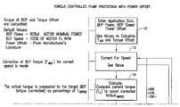
- FIG. 4is a block diagram of the controller shown in FIG. 3 for performing torque controlled pump protection with power offset that is the subject matter of the present invention.
- FIG. 5is a line graph showing the pump conditions based on the ratio of the actual torque value to the corrected torque value.
- FIG. 1shows a flow chart having steps for performing a method according to the present invention for controlling the operation of a pump generally indicated as 100 ( FIG. 3 ), featuring steps of either adjusting the operation of the pump 100 , or issuing a warning to a user of the pump 100 of an undesirable operating condition, or both, based on a comparison of an actual torque value and a corrected torque value.
- the steps of the methodare performed by a controller 102 of the pump 100 and motor 103 shown in FIGS. 3 and 4 .
- the inventionis described in relation to a pump, although the scope of the invention is intended to include a centrifugal pump or other centrifugal device, such as a blower, mixer or other suitable centrifugal device.
- the controller 102has an enter application data module 102 a ( FIG. 4 ) that first performs a step 10 for entering application data, including entering default values for the BEP power (90% of motor nominal power), BEP speed (100% of motor FL RPM) and a power offset typically from the pump manufacturer's literature. These default values are used to calculate the torque at the Best Efficiency Point (BEP) and the torque offset.
- BEP power90% of motor nominal power
- BEP speed100% of motor FL RPM
- a power offsettypically from the pump manufacturer's literature.
- values different from the default valuescan be used for BEP power and BEP speed based on manufacturer's literature.
- the threshold valuesmust be input during field setup for DRY RUN (A %), MIN FLOW (B %) and RUNOUT FLOW (C %) based on system operating conditions and pump performance data in order to differentiate between shut-off, dry running and run-out conditions.
- the algorithm set forth hereincalculates and displays values of Calc Torque % and Corr BEP torque % at the current operating point to facilitate set-up of A, B and C %.
- the controller 102has a correct for speed module 102 b ( FIG. 4 ) for performing a step 12 for making a correction of the BEP torque (T BEP ) for the current speed of the motor 103 ( FIG. 3 ) and power offset compensation using the equations set forth below in relation to the description of FIGS. 2A and 2B .
- Step 12the correction of the BEP torque (T BEP ) is made for actual speed conditions with the power offset.
- This correctionis particularly important for pumps having small or large HP motors. See FIGS. 2A and 2B , in which FIG. 2A shows a power offset compensation graph for a torque controlled pump protection with 0.2 HP Power Offset (5 HP Motor), while FIG. 2B shows a power offset compensation graph for a torque controlled pump protection with ⁇ 0.9 HP Power Offset (100 HP Motor).
- the mechanical power offset correctionadjusts the corrected BEP torque which is important for smaller HP units operating at lower speeds.
- the deviation between the Corrected (calculated) BEP Torque % w/o compensation for mechanical losses and Actual Motor Torque %is significant at low speeds. This is amplified in curves showing the Calc T % with and without compensation for power offset (mechanical losses).
- the power offset correctioneffectively extends the useable speed and application range. Ideally the Calc T % should be a horizontal line extending across the entire motor speed range for a constant system. Note without the power offset compensation the useable speed range of the application becomes limited. As shown in FIG.
- the present inventionextends the operating range of a 5 hp 3600 rpm motor from 2400–3600 rpm (33% of speed range) without mechanical loss compensation to 500–3600 rpm (85%+ of the speed range) with mechanical loss compensation. This is more than a 150% improvement in the operating range.
- the curve for Calc Test Trq % without power offsetrises considerably at lower speeds due to undercompensation of the Corr BEP Trq % value.
- the Calc Test Trq % value(Actual Torque/Corr Bep Trq %) should be a horizontal line since both of these torques theoretically vary according to the square of the speed change.
- FIG. 2Bshows a chart with a slight negative power offset ( ⁇ 0.9% of nameplate power) which will extend the operating speed range of the torque based pump protection.
- the slight negative power offsetis due to a slight overcompensation in the corrected BEP torque % calculation at low speeds.
- thishas a pronounced effect in the Calc T % ratio (Actual motor torque/Corrected BEP torque). (Note, for the small HP motor previously discussed with respect to FIG. 2A , the correction was positive (+4% nameplate power) due to under compensation by seal and bearing mechanical losses.
- the present inventionextends the operating range of a 100 hp 1800 rpm motor from 900–1800 rpm (50% of speed range) without mechanical loss compensation to the tested 300–1800 rpm (83%+ of the speed range) with mechanical loss compensation. This is a 66% improvement in the operating range.
- the curve for Calc Test Trq % without power offsetdescends considerably at lower speeds due to a slight overcompensation of the Corr BEP Trq % value.
- the CalcTest Trq % value(Actual Torque/Corr Bep Trq %) should be a horizontal line since both of these torques theoretically vary according to the square of the speed change.
- the power offsetcan compensate small and large HP motors to extend the operating speed range for torque based pump protection.
- the algorithm set forth hereincorrects the torque at BEP for actual operating speed and power offset based on the following equations.
- Pwr OffsetPower, Hp or Kw (mechanical losses such as seals and bearings) (the values of these parameters are provided in the manufacturer's literature);
- the controller 102has an evaluate module 102 c ( FIG. 4 ) for performing a step 14 for comparing the actual (or current) torque to a speed corrected torque (T BEP(C) ), which is a target BEP torque (corrected) as a percentage of the best efficiency point torque (T BEP(C) ).
- T BEP(C)speed corrected torque
- T BEP(C)target BEP torque (corrected) as a percentage of the best efficiency point torque
- the controller 102has a determine status module 102 d ( FIG. 4 ) for performing a step 16 for determining the pump condition based upon the torque comparison, where
- the determine status module 102 ddetermines the status of the pump condition to be not O.K. and either in one case if the torque comparison is less than B % passed the controller to a step 18 for determining whether the pump condition is a MIN FLOW or DRY RUN condition, or in the other case if the torque comparison is greater than C % pass the controller 102 to a step 20 for controlling the operation of the pump 100 based on a RUNOUT condition.
- the RUNOUT condition module 102 fadjusts the operation of the pump 100 , or issues a warning of the RUNOUT condition, or both.
- the RUNOUT condition module 102 fcan adjust the operation of the pump 100 by, for example, decreasing the speed of the pump to meet C % requirement.
- the RUNOUT condition module 102 fcan also auto reset the pump 100 once the minimum speed is reached.
- the deceleration ramp of the pump motormay be adjustable.
- the RUNOUT condition module 102 fwill perform the RUNOUT fault routine after a predetermined protection delay to avoid nuisance trips caused by system transients. After performing step 20 , the RUNOUT condition module 102 f returns the controller 102 to the step 12 for correcting for speed once the RUNOUT condition clears.
- a RUNOUT protection conditionis declared if the ratio of the Act Motor Torque/Corrected BEP Torque>C %.
- a typical settingis >120% of BEP Torque.
- the protection delay periodcan be set prior to declaring a RUNOUT condition. If the RUNOUT condition clears, the speed will be adjusted upward until the C % is reached or the original setpoint is achieved. The deceleration ramp during a RUNOUT condition can be adjusted by the user to suit the application.
- the drivecan also be set to automatically reset a RUNOUT condition once the unit has reached minimum speed to check if the system transient condition has cleared. The number of resets and time between resets is adjustable by the user. Once the number of resets is exhausted, if the condition has not cleared, the unit will remain at minimum speed until action is taken by the user.
- the controller 102has a DRY RUN or MIN FLOW condition module 102 e that determines whether the pump is in a DRY RUN condition or a MIN FLOW condition based on the value of A %.
- the DRY RUN or MIN FLOW condition module 102 epass the controller 102 to a step 22 for controlling the operation of the pump 100 based on a DRY RUN condition. In comparison, if the torque comparison is greater than A %, then the DRY RUN or MIN FLOW condition module 102 e pass the controller 102 to a step 24 for controlling the operation of the pump 100 based on a MIN FLOW condition.
- the controller 102has a DRY RUN condition module 102 g that determines in the step 22 the status of the pump to be not O.K., and either adjusts the operation of the pump 100 , or issues a warning of the DRY RUN condition, or both.
- the DRY RUN condition module 102 gcan adjust the operation of the pump 100 by, for example, shutting down the pump. Unlike the RUNOUT condition, the DRY RUN condition module 102 g cannot auto reset the pump 100 . Instead, the user must re-start the pump. The DRY RUN condition module 102 g will perform the DRY RUN fault routine after a predetermined protection delay to avoid nuisance trips caused by system transients. After performing step 22 , the DRY RUN condition module 102 g passes the controller 102 to the step 26 for performing the standard operation functionality when done.
- the DRY RUN protection conditionis declared if the ratio of the Act Motor Torque/Corrected BEP Torque ⁇ A %.
- a typical settingis 40–65% of BEP Torque, although the scope of the invention is not intended to be limited to any particular percentage.
- the reaction of the controller 102is programmed to either warn the user with no further action taken or fault and shutdown the pump 100 .
- a protection delay periodcan be set by the user in the initial set-up prior to declaring the DRY RUN condition. However, the controller 102 cannot be set to automatically reset a fault condition. Once the pump has faulted it will remain off until re-started by the user.
- the controller 102has a MIN FLOW condition module 102 h that determines in the step 24 the status of the pump to be not O.K., and either adjusts the operation of the pump 100 , or issues a warning of the MIN FLOW condition, or both.
- the MIN FLOW condition module 102 hcan adjust the operation of the pump 100 by, for example, going to a minimum speed (MINSPEED) or shutting down the pump 100 .
- MINSPEEDminimum speed
- the MIN FLOW condition module 102 hcan auto reset the pump 100 .
- the MIN FLOW condition module 102 hwill perform the MIN FLOW fault routine after a predetermined protection delay to avoid nuisance trips caused by system transients. After performing step 24 , the MIN FLOW condition module 102 h resumes the standard operation functionality in step 26 when done.
- the MIN FLOW protection conditionis declared if the ratio of the Act Motor Torque/Corrected BEP Torque ⁇ B % but >A %.
- a typical setting for the B %is 65–70% of BEP Torque, although the scope of the invention is not intended to be limited to any particular percentage.
- the reaction of the controller 102can be set to either warn the user with no further action taken, warn the user and slow down to a safe minimum operating speed (alarm & control) or fault and shutdown the unit.
- the protection delay periodcan be set prior to declaring a MIN FLOW condition.
- the controller 102can also be set to automatically reset the alarm and control condition or fault to check if the system transient condition has cleared.
- the number of resets and time between resetsis pre-set with default values in the initial set-up and adjustable by the user. Once the number of resets is exhausted, if the condition has not cleared, the pump will remain off until re-started by the user.
- FIG. 4The Controller 102
- FIG. 4shows the controller 102 in greater detail, including the various modules 102 a , 102 b , . . . , 102 i discussed above.
- the controller 102also includes a control processor module 102 j for controlling the operation of the controller 102 .
- the controller 102also includes an input/output module (not shown) for receiving and sending data, including control data to control the operation of the pump 100 .
- the various modules 102 a , 102 b , . . . , 102 i , 102 jmay be implemented using hardware, software, or a combination thereof.
- one or more of the various modules 102 a , 102 b , . . . , 102 i , 102 jwould be a microprocessor-based architecture having a microprocessor, a random access memory (RAM), a read only memory (ROM), input/output devices and control, data and address buses connecting the same.
- RAMrandom access memory
- ROMread only memory
- a person skilled in the artwould be able to program such a microprocessor-based implementation to perform the functionality described herein without undue experimentation.
- the scope of the inventionis not intended to be limited to any particular implementation of the various modules 102 a , 102 b , . . . , 102 i , 102 j.
- the inventioncomprises the features of construction, combination of elements, and arrangement of parts which will be exemplified in the construction hereinafter set forth.
Landscapes
- Engineering & Computer Science (AREA)
- General Engineering & Computer Science (AREA)
- Mechanical Engineering (AREA)
- Control Of Non-Positive-Displacement Pumps (AREA)
- Control Of Positive-Displacement Pumps (AREA)
Abstract
Description
Corr BepTIn-Lbs=[[Act Spd/Bep Spd]2×[Tbep−Trq Offset]]+[[Act Spd/Bep Spd]×Trq Offset].
Corr BepTIn-Lbs=[[Act Spd/Bep Spd]2×[Tbep−Trq Offset]]+[Trq Offset], where:
Tbep In-Lbs=[[63025×Bep Power]/Bep Spd](Bep Power is inHP);
Tbep In-Lbs=[[63025×[Bep Power/0.74569]]/Bep Spd] (Bep Power is inKw);
Trq Offset In-Lbs=[[63025×Pwr Offset]/Bep Spd](Pwr Offset is inHP)
Trq Offset In-lbs=[[63025×[Pwr Offset/0.74569]]/Bep Spd] (Pwr Offset is inKw)
Claims (62)
Priority Applications (5)
| Application Number | Priority Date | Filing Date | Title |
|---|---|---|---|
| US10/846,946US7080508B2 (en) | 2004-05-13 | 2004-05-13 | Torque controlled pump protection with mechanical loss compensation |
| PCT/IB2005/001309WO2005111473A2 (en) | 2004-05-13 | 2005-05-13 | Torque controlled pump protection with mechanical loss compensation |
| CN2005800150953ACN1977115B (en) | 2004-05-13 | 2005-05-13 | Pump protection with torque control with mechanical loss compensation |
| DE112005001075TDE112005001075B9 (en) | 2004-05-13 | 2005-05-13 | Torque-controlled pump protection device with mechanical loss compensation |
| FI20061098AFI122792B (en) | 2004-05-13 | 2006-12-11 | Centrifugal pump, centrifugal fan, centrifugal mixer or centrifugal fan, method and control unit for functional control thereof and device with control unit for functional control thereof |
Applications Claiming Priority (1)
| Application Number | Priority Date | Filing Date | Title |
|---|---|---|---|
| US10/846,946US7080508B2 (en) | 2004-05-13 | 2004-05-13 | Torque controlled pump protection with mechanical loss compensation |
Publications (2)
| Publication Number | Publication Date |
|---|---|
| US20050252205A1 US20050252205A1 (en) | 2005-11-17 |
| US7080508B2true US7080508B2 (en) | 2006-07-25 |
Family
ID=35308094
Family Applications (1)
| Application Number | Title | Priority Date | Filing Date |
|---|---|---|---|
| US10/846,946Expired - LifetimeUS7080508B2 (en) | 2004-05-13 | 2004-05-13 | Torque controlled pump protection with mechanical loss compensation |
Country Status (5)
| Country | Link |
|---|---|
| US (1) | US7080508B2 (en) |
| CN (1) | CN1977115B (en) |
| DE (1) | DE112005001075B9 (en) |
| FI (1) | FI122792B (en) |
| WO (1) | WO2005111473A2 (en) |
Cited By (37)
| Publication number | Priority date | Publication date | Assignee | Title |
|---|---|---|---|---|
| US20070160480A1 (en)* | 2006-01-06 | 2007-07-12 | Itt Industries | No water / dead head detection pump protection algorithm |
| US20070183902A1 (en)* | 2004-08-26 | 2007-08-09 | Pentair Water Pool And Spa, Inc. | Anti-entrapment and anti-dead head function |
| US20070204603A1 (en)* | 2006-01-20 | 2007-09-06 | Jacobs Michael H | Actuator control system and method |
| US20070212229A1 (en)* | 2006-03-08 | 2007-09-13 | Itt Manufacturing Enterprises, Inc. | Method and apparatus for pump protection without the use of traditional sensors |
| US20070212210A1 (en)* | 2006-03-08 | 2007-09-13 | Itt Manufacturing Enterprises, Inc. | Method for determining pump flow without the use of traditional sensors |
| US20080288115A1 (en)* | 2007-05-14 | 2008-11-20 | Flowserve Management Company | Intelligent pump system |
| US20090097986A1 (en)* | 2006-08-30 | 2009-04-16 | Daikin Industries, Ltd. | Oil pressure unit and speed control method of motor in oil pressure unit |
| WO2009079447A1 (en)* | 2007-12-14 | 2009-06-25 | Itt Manufacturing Enterprises, Inc. | Synchronous torque balance in multiple pump systems |
| US20090252617A1 (en)* | 2004-12-14 | 2009-10-08 | Siemens Aktiengesellschaft | Method for operation of a compressor supplied by a power converter |
| US20100034665A1 (en)* | 2005-06-21 | 2010-02-11 | Zhiyong Zhong | Control system for a pump |
| US20100312398A1 (en)* | 2009-06-09 | 2010-12-09 | Melissa Drechsel Kidd | Safety System and Method for Pump and Motor |
| US20100308963A1 (en)* | 2009-06-09 | 2010-12-09 | Melissa Drechsel Kidd | System and Method for Motor Drive Control Pad and Drive Terminals |
| US20100310382A1 (en)* | 2009-06-09 | 2010-12-09 | Melissa Drechsel Kidd | Method of Controlling a Pump and Motor |
| US20110206537A1 (en)* | 2010-02-24 | 2011-08-25 | Harris Waste Management Group, Inc. | Hybrid electro-hydraulic power device |
| DE102007009301B4 (en)* | 2006-03-08 | 2012-03-29 | Itt Manufacturing Enterprises, Inc. | Method and device for pump protection without the use of traditional sensors |
| US8444394B2 (en) | 2003-12-08 | 2013-05-21 | Sta-Rite Industries, Llc | Pump controller system and method |
| US8465262B2 (en) | 2004-08-26 | 2013-06-18 | Pentair Water Pool And Spa, Inc. | Speed control |
| US8480373B2 (en) | 2004-08-26 | 2013-07-09 | Pentair Water Pool And Spa, Inc. | Filter loading |
| US8500413B2 (en) | 2004-08-26 | 2013-08-06 | Pentair Water Pool And Spa, Inc. | Pumping system with power optimization |
| US8573952B2 (en) | 2004-08-26 | 2013-11-05 | Pentair Water Pool And Spa, Inc. | Priming protection |
| US20130323084A1 (en)* | 2011-05-17 | 2013-12-05 | Clearwater Controls Limited | Control Device And Pump Apparatus |
| US8602743B2 (en) | 2008-10-06 | 2013-12-10 | Pentair Water Pool And Spa, Inc. | Method of operating a safety vacuum release system |
| US8801389B2 (en) | 2004-08-26 | 2014-08-12 | Pentair Water Pool And Spa, Inc. | Flow control |
| US9404500B2 (en) | 2004-08-26 | 2016-08-02 | Pentair Water Pool And Spa, Inc. | Control algorithm of variable speed pumping system |
| US9568005B2 (en) | 2010-12-08 | 2017-02-14 | Pentair Water Pool And Spa, Inc. | Discharge vacuum relief valve for safety vacuum release system |
| US9745974B2 (en) | 2011-12-07 | 2017-08-29 | Flow Control LLC | Pump using multi voltage electronics with run dry and over current protection |
| US9885360B2 (en) | 2012-10-25 | 2018-02-06 | Pentair Flow Technologies, Llc | Battery backup sump pump systems and methods |
| US9977433B1 (en) | 2017-05-05 | 2018-05-22 | Hayward Industries, Inc. | Automatic pool cleaner traction correction |
| US10024325B2 (en) | 2011-12-07 | 2018-07-17 | Flow Control Llc. | Pump using multi voltage electronics with run dry and over current protection |
| US10353005B2 (en) | 2017-07-13 | 2019-07-16 | Itt Manufacturing Enterprises Llc | Technique for self learning motor load profile |
| US10422332B2 (en) | 2013-03-11 | 2019-09-24 | Circor Pumps North America, Llc | Intelligent pump monitoring and control system |
| US10465676B2 (en) | 2011-11-01 | 2019-11-05 | Pentair Water Pool And Spa, Inc. | Flow locking system and method |
| US10947968B2 (en) | 2018-06-15 | 2021-03-16 | Itt Manufacturing Enterprises Llc | Smart pump for remotely sending realtime data to a smart device |
| US10947981B2 (en) | 2004-08-26 | 2021-03-16 | Pentair Water Pool And Spa, Inc. | Variable speed pumping system and method |
| US11018610B2 (en) | 2017-01-27 | 2021-05-25 | Franklin Electric Co., Inc. | Motor drive system and method |
| US11499544B2 (en)* | 2016-08-31 | 2022-11-15 | Halliburton Energy Services, Inc. | Pressure pump performance monitoring system using torque measurements |
| EP4390141A1 (en)* | 2022-12-20 | 2024-06-26 | Wilo Se | Method of detecting and/or classifying a blockage of a waste water pump |
Families Citing this family (17)
| Publication number | Priority date | Publication date | Assignee | Title |
|---|---|---|---|---|
| US20080095639A1 (en)* | 2006-10-13 | 2008-04-24 | A.O. Smith Corporation | Controller for a motor and a method of controlling the motor |
| US8177520B2 (en) | 2004-04-09 | 2012-05-15 | Regal Beloit Epc Inc. | Controller for a motor and a method of controlling the motor |
| US7925385B2 (en)* | 2006-03-08 | 2011-04-12 | Itt Manufacturing Enterprises, Inc | Method for optimizing valve position and pump speed in a PID control valve system without the use of external signals |
| CN103206388B (en)* | 2006-03-08 | 2016-09-07 | Itt制造企业有限责任公司 | Do not use pump guard method and the equipment of traditional sensors |
| JP5553967B2 (en)* | 2007-04-13 | 2014-07-23 | レスメド・リミテッド | Method and system for motor fault detection |
| AU2009298834B2 (en) | 2008-10-01 | 2015-07-16 | Regal Beloit America, Inc. | Controller for a motor and a method of controlling the motor |
| CN102536770B (en)* | 2010-12-31 | 2015-03-25 | 陈俊平 | Water pump with self-protection function |
| CN104350278B (en)* | 2012-04-11 | 2017-10-10 | Itt制造企业有限责任公司 | Method for protection of rotary positive displacement pumps |
| US10495084B2 (en) | 2012-04-11 | 2019-12-03 | Itt Manufacturing Enterprises Llc | Method for twin screw positive displacement pump protection |
| US20140277612A1 (en)* | 2013-03-14 | 2014-09-18 | General Electric Company | Automatic generation of a dynamic pre-start checklist |
| JP6308029B2 (en)* | 2014-06-02 | 2018-04-11 | 三菱電機株式会社 | Hot water storage water heater |
| DE102016004458A1 (en)* | 2016-04-15 | 2017-10-19 | Wilo Se | Centrifugal pump unit and method for its operation |
| WO2018099982A1 (en) | 2016-11-30 | 2018-06-07 | Saint-Gobain Performance Plastics Rencol Limited | Adjustable torque assembly |
| CN106685300B (en)* | 2016-12-22 | 2019-01-11 | 浙江工业大学 | The dynamic compensation method of industry measurement pump special digital frequency-variable controller |
| CN107842491A (en)* | 2017-10-31 | 2018-03-27 | 中国有色(沈阳)泵业有限公司 | A kind of membrane pump condition detection method |
| US11035209B2 (en)* | 2018-02-02 | 2021-06-15 | Magnetic Pumping Solutions | Method and system for controlling downhole pumping systems |
| US12305650B2 (en)* | 2020-07-24 | 2025-05-20 | Eaton Intelligent Power Limited | Control system for a fluid management system |
Citations (14)
| Publication number | Priority date | Publication date | Assignee | Title |
|---|---|---|---|---|
| US4091617A (en)* | 1977-05-11 | 1978-05-30 | Eaton Corporation | Hydraulic controller |
| US4462210A (en)* | 1981-07-31 | 1984-07-31 | Sundstrand Corporation | Input torque control for a variable displacement hydraulic transmission |
| US4470092A (en) | 1982-09-27 | 1984-09-04 | Allen-Bradley Company | Programmable motor protector |
| US4490094A (en)* | 1982-06-15 | 1984-12-25 | Gibbs Sam G | Method for monitoring an oil well pumping unit |
| US4707139A (en)* | 1985-11-22 | 1987-11-17 | Farrell Corporation | Control system and method for continuous mixer with moving surface discharge device |
| US4827197A (en) | 1987-05-22 | 1989-05-02 | Beckman Instruments, Inc. | Method and apparatus for overspeed protection for high speed centrifuges |
| US5649893A (en) | 1996-05-22 | 1997-07-22 | Hitachi Koki Co., Ltd. | Centrifugal apparatus having series-implemented protection means |
| US5726881A (en) | 1994-08-17 | 1998-03-10 | Hitachi Koki Co,. Ltd. | Centrifugal apparatus with overspeed protection |
| US5736823A (en) | 1994-05-27 | 1998-04-07 | Emerson Electric Co. | Constant air flow control apparatus and method |
| US5742522A (en) | 1996-04-01 | 1998-04-21 | General Electric Company | Adaptive, on line, statistical method and apparatus for detection of broken bars in motors by passive motor current monitoring and digital torque estimation |
| US5917688A (en) | 1996-10-18 | 1999-06-29 | Hitachi Koki Co., Ltd. | Centrifugal apparatus with protection |
| US6501629B1 (en) | 2000-10-26 | 2002-12-31 | Tecumseh Products Company | Hermetic refrigeration compressor motor protector |
| US6679820B2 (en) | 2000-04-11 | 2004-01-20 | Kendro Laboratory Products, Lp | Method for energy management and overspeed protection of a centrifuge |
| US6933693B2 (en)* | 2002-11-08 | 2005-08-23 | Eaton Corporation | Method and apparatus of detecting disturbances in a centrifugal pump |
Family Cites Families (7)
| Publication number | Priority date | Publication date | Assignee | Title |
|---|---|---|---|---|
| DE3914342A1 (en)* | 1989-04-29 | 1990-11-08 | Grundfos Int | Centrifugal pumping plant with electronic characteristic setting - secures redn. of speed and power as vol. flow increases from zero throughout range of control |
| US5930092A (en)* | 1992-01-17 | 1999-07-27 | Load Controls, Incorporated | Power monitoring |
| US5467012A (en)* | 1994-05-10 | 1995-11-14 | Load Controls Incorporated | Power monitoring |
| PL176270B1 (en)* | 1995-07-14 | 1999-05-31 | Kiełtyka Maciej | System for automatically protecting motors of circulating and recirculating pumps |
| US6260004B1 (en)* | 1997-12-31 | 2001-07-10 | Innovation Management Group, Inc. | Method and apparatus for diagnosing a pump system |
| US6464464B2 (en)* | 1999-03-24 | 2002-10-15 | Itt Manufacturing Enterprises, Inc. | Apparatus and method for controlling a pump system |
| US6591697B2 (en)* | 2001-04-11 | 2003-07-15 | Oakley Henyan | Method for determining pump flow rates using motor torque measurements |
- 2004
- 2004-05-13USUS10/846,946patent/US7080508B2/ennot_activeExpired - Lifetime
- 2005
- 2005-05-13WOPCT/IB2005/001309patent/WO2005111473A2/enactiveApplication Filing
- 2005-05-13CNCN2005800150953Apatent/CN1977115B/ennot_activeExpired - Lifetime
- 2005-05-13DEDE112005001075Tpatent/DE112005001075B9/ennot_activeExpired - Lifetime
- 2006
- 2006-12-11FIFI20061098Apatent/FI122792B/enactiveIP Right Grant
Patent Citations (14)
| Publication number | Priority date | Publication date | Assignee | Title |
|---|---|---|---|---|
| US4091617A (en)* | 1977-05-11 | 1978-05-30 | Eaton Corporation | Hydraulic controller |
| US4462210A (en)* | 1981-07-31 | 1984-07-31 | Sundstrand Corporation | Input torque control for a variable displacement hydraulic transmission |
| US4490094A (en)* | 1982-06-15 | 1984-12-25 | Gibbs Sam G | Method for monitoring an oil well pumping unit |
| US4470092A (en) | 1982-09-27 | 1984-09-04 | Allen-Bradley Company | Programmable motor protector |
| US4707139A (en)* | 1985-11-22 | 1987-11-17 | Farrell Corporation | Control system and method for continuous mixer with moving surface discharge device |
| US4827197A (en) | 1987-05-22 | 1989-05-02 | Beckman Instruments, Inc. | Method and apparatus for overspeed protection for high speed centrifuges |
| US5736823A (en) | 1994-05-27 | 1998-04-07 | Emerson Electric Co. | Constant air flow control apparatus and method |
| US5726881A (en) | 1994-08-17 | 1998-03-10 | Hitachi Koki Co,. Ltd. | Centrifugal apparatus with overspeed protection |
| US5742522A (en) | 1996-04-01 | 1998-04-21 | General Electric Company | Adaptive, on line, statistical method and apparatus for detection of broken bars in motors by passive motor current monitoring and digital torque estimation |
| US5649893A (en) | 1996-05-22 | 1997-07-22 | Hitachi Koki Co., Ltd. | Centrifugal apparatus having series-implemented protection means |
| US5917688A (en) | 1996-10-18 | 1999-06-29 | Hitachi Koki Co., Ltd. | Centrifugal apparatus with protection |
| US6679820B2 (en) | 2000-04-11 | 2004-01-20 | Kendro Laboratory Products, Lp | Method for energy management and overspeed protection of a centrifuge |
| US6501629B1 (en) | 2000-10-26 | 2002-12-31 | Tecumseh Products Company | Hermetic refrigeration compressor motor protector |
| US6933693B2 (en)* | 2002-11-08 | 2005-08-23 | Eaton Corporation | Method and apparatus of detecting disturbances in a centrifugal pump |
Cited By (87)
| Publication number | Priority date | Publication date | Assignee | Title |
|---|---|---|---|---|
| US10642287B2 (en) | 2003-12-08 | 2020-05-05 | Pentair Water Pool And Spa, Inc. | Pump controller system and method |
| US10241524B2 (en) | 2003-12-08 | 2019-03-26 | Pentair Water Pool And Spa, Inc. | Pump controller system and method |
| US10289129B2 (en) | 2003-12-08 | 2019-05-14 | Pentair Water Pool And Spa, Inc. | Pump controller system and method |
| US10409299B2 (en) | 2003-12-08 | 2019-09-10 | Pentair Water Pool And Spa, Inc. | Pump controller system and method |
| US9399992B2 (en) | 2003-12-08 | 2016-07-26 | Pentair Water Pool And Spa, Inc. | Pump controller system and method |
| US9371829B2 (en) | 2003-12-08 | 2016-06-21 | Pentair Water Pool And Spa, Inc. | Pump controller system and method |
| US9328727B2 (en) | 2003-12-08 | 2016-05-03 | Pentair Water Pool And Spa, Inc. | Pump controller system and method |
| US10416690B2 (en) | 2003-12-08 | 2019-09-17 | Pentair Water Pool And Spa, Inc. | Pump controller system and method |
| US8540493B2 (en) | 2003-12-08 | 2013-09-24 | Sta-Rite Industries, Llc | Pump control system and method |
| US8444394B2 (en) | 2003-12-08 | 2013-05-21 | Sta-Rite Industries, Llc | Pump controller system and method |
| US8465262B2 (en) | 2004-08-26 | 2013-06-18 | Pentair Water Pool And Spa, Inc. | Speed control |
| US8602745B2 (en)* | 2004-08-26 | 2013-12-10 | Pentair Water Pool And Spa, Inc. | Anti-entrapment and anti-dead head function |
| US10947981B2 (en) | 2004-08-26 | 2021-03-16 | Pentair Water Pool And Spa, Inc. | Variable speed pumping system and method |
| US10871001B2 (en) | 2004-08-26 | 2020-12-22 | Pentair Water Pool And Spa, Inc. | Filter loading |
| US10871163B2 (en) | 2004-08-26 | 2020-12-22 | Pentair Water Pool And Spa, Inc. | Pumping system and method having an independent controller |
| US9777733B2 (en) | 2004-08-26 | 2017-10-03 | Pentair Water Pool And Spa, Inc. | Flow control |
| US10731655B2 (en) | 2004-08-26 | 2020-08-04 | Pentair Water Pool And Spa, Inc. | Priming protection |
| US10240604B2 (en) | 2004-08-26 | 2019-03-26 | Pentair Water Pool And Spa, Inc. | Pumping system with housing and user interface |
| US10415569B2 (en) | 2004-08-26 | 2019-09-17 | Pentair Water Pool And Spa, Inc. | Flow control |
| US10240606B2 (en) | 2004-08-26 | 2019-03-26 | Pentair Water Pool And Spa, Inc. | Pumping system with two way communication |
| US20070183902A1 (en)* | 2004-08-26 | 2007-08-09 | Pentair Water Pool And Spa, Inc. | Anti-entrapment and anti-dead head function |
| US9051930B2 (en) | 2004-08-26 | 2015-06-09 | Pentair Water Pool And Spa, Inc. | Speed control |
| US11073155B2 (en) | 2004-08-26 | 2021-07-27 | Pentair Water Pool And Spa, Inc. | Pumping system with power optimization |
| US9605680B2 (en) | 2004-08-26 | 2017-03-28 | Pentair Water Pool And Spa, Inc. | Control algorithm of variable speed pumping system |
| US9932984B2 (en) | 2004-08-26 | 2018-04-03 | Pentair Water Pool And Spa, Inc. | Pumping system with power optimization |
| US8480373B2 (en) | 2004-08-26 | 2013-07-09 | Pentair Water Pool And Spa, Inc. | Filter loading |
| US8500413B2 (en) | 2004-08-26 | 2013-08-06 | Pentair Water Pool And Spa, Inc. | Pumping system with power optimization |
| US8840376B2 (en) | 2004-08-26 | 2014-09-23 | Pentair Water Pool And Spa, Inc. | Pumping system with power optimization |
| US10527042B2 (en) | 2004-08-26 | 2020-01-07 | Pentair Water Pool And Spa, Inc. | Speed control |
| US8573952B2 (en) | 2004-08-26 | 2013-11-05 | Pentair Water Pool And Spa, Inc. | Priming protection |
| US10502203B2 (en) | 2004-08-26 | 2019-12-10 | Pentair Water Pool And Spa, Inc. | Speed control |
| US10480516B2 (en) | 2004-08-26 | 2019-11-19 | Pentair Water Pool And Spa, Inc. | Anti-entrapment and anti-deadhead function |
| US9404500B2 (en) | 2004-08-26 | 2016-08-02 | Pentair Water Pool And Spa, Inc. | Control algorithm of variable speed pumping system |
| US9551344B2 (en) | 2004-08-26 | 2017-01-24 | Pentair Water Pool And Spa, Inc. | Anti-entrapment and anti-dead head function |
| US11391281B2 (en) | 2004-08-26 | 2022-07-19 | Pentair Water Pool And Spa, Inc. | Priming protection |
| US8801389B2 (en) | 2004-08-26 | 2014-08-12 | Pentair Water Pool And Spa, Inc. | Flow control |
| US20090252617A1 (en)* | 2004-12-14 | 2009-10-08 | Siemens Aktiengesellschaft | Method for operation of a compressor supplied by a power converter |
| US8070456B2 (en)* | 2004-12-14 | 2011-12-06 | Siemens Aktiengesellschaft | Method for preventing power surge in a compressor supplied by a power converter by direct torque control |
| US20100034665A1 (en)* | 2005-06-21 | 2010-02-11 | Zhiyong Zhong | Control system for a pump |
| US20070160480A1 (en)* | 2006-01-06 | 2007-07-12 | Itt Industries | No water / dead head detection pump protection algorithm |
| US8011895B2 (en)* | 2006-01-06 | 2011-09-06 | Itt Manufacturing Enterprises, Inc. | No water / dead head detection pump protection algorithm |
| US20070204603A1 (en)* | 2006-01-20 | 2007-09-06 | Jacobs Michael H | Actuator control system and method |
| US7621123B2 (en)* | 2006-01-20 | 2009-11-24 | Jacobs Michael H | Actuator control system and method |
| US20070212210A1 (en)* | 2006-03-08 | 2007-09-13 | Itt Manufacturing Enterprises, Inc. | Method for determining pump flow without the use of traditional sensors |
| US20070212229A1 (en)* | 2006-03-08 | 2007-09-13 | Itt Manufacturing Enterprises, Inc. | Method and apparatus for pump protection without the use of traditional sensors |
| US8303260B2 (en) | 2006-03-08 | 2012-11-06 | Itt Manufacturing Enterprises, Inc. | Method and apparatus for pump protection without the use of traditional sensors |
| DE102007009301B4 (en)* | 2006-03-08 | 2012-03-29 | Itt Manufacturing Enterprises, Inc. | Method and device for pump protection without the use of traditional sensors |
| US7945411B2 (en)* | 2006-03-08 | 2011-05-17 | Itt Manufacturing Enterprises, Inc | Method for determining pump flow without the use of traditional sensors |
| US20090097986A1 (en)* | 2006-08-30 | 2009-04-16 | Daikin Industries, Ltd. | Oil pressure unit and speed control method of motor in oil pressure unit |
| US20080288115A1 (en)* | 2007-05-14 | 2008-11-20 | Flowserve Management Company | Intelligent pump system |
| US8774972B2 (en) | 2007-05-14 | 2014-07-08 | Flowserve Management Company | Intelligent pump system |
| US8328523B2 (en) | 2007-12-14 | 2012-12-11 | Itt Manufacturing Enterprises, Inc. | Synchronous torque balance in multiple pump systems |
| CN101896871B (en)* | 2007-12-14 | 2015-06-10 | Itt制造企业公司 | Synchronous torque balance in multiple pump systems |
| WO2009079447A1 (en)* | 2007-12-14 | 2009-06-25 | Itt Manufacturing Enterprises, Inc. | Synchronous torque balance in multiple pump systems |
| US20090304521A1 (en)* | 2007-12-14 | 2009-12-10 | Itt Manufacturing Enterprises, Inc | Synchronous torque balance in multiple pump systems |
| US10724263B2 (en) | 2008-10-06 | 2020-07-28 | Pentair Water Pool And Spa, Inc. | Safety vacuum release system |
| US9726184B2 (en) | 2008-10-06 | 2017-08-08 | Pentair Water Pool And Spa, Inc. | Safety vacuum release system |
| US8602743B2 (en) | 2008-10-06 | 2013-12-10 | Pentair Water Pool And Spa, Inc. | Method of operating a safety vacuum release system |
| US10590926B2 (en) | 2009-06-09 | 2020-03-17 | Pentair Flow Technologies, Llc | Method of controlling a pump and motor |
| US9556874B2 (en)* | 2009-06-09 | 2017-01-31 | Pentair Flow Technologies, Llc | Method of controlling a pump and motor |
| US11493034B2 (en) | 2009-06-09 | 2022-11-08 | Pentair Flow Technologies, Llc | Method of controlling a pump and motor |
| US20100312398A1 (en)* | 2009-06-09 | 2010-12-09 | Melissa Drechsel Kidd | Safety System and Method for Pump and Motor |
| US9712098B2 (en) | 2009-06-09 | 2017-07-18 | Pentair Flow Technologies, Llc | Safety system and method for pump and motor |
| US20100308963A1 (en)* | 2009-06-09 | 2010-12-09 | Melissa Drechsel Kidd | System and Method for Motor Drive Control Pad and Drive Terminals |
| US8564233B2 (en) | 2009-06-09 | 2013-10-22 | Sta-Rite Industries, Llc | Safety system and method for pump and motor |
| US20100310382A1 (en)* | 2009-06-09 | 2010-12-09 | Melissa Drechsel Kidd | Method of Controlling a Pump and Motor |
| US8436559B2 (en) | 2009-06-09 | 2013-05-07 | Sta-Rite Industries, Llc | System and method for motor drive control pad and drive terminals |
| US20110206537A1 (en)* | 2010-02-24 | 2011-08-25 | Harris Waste Management Group, Inc. | Hybrid electro-hydraulic power device |
| US8801407B2 (en) | 2010-02-24 | 2014-08-12 | Harris Waste Management Group, Inc. | Hybrid electro-hydraulic power device |
| US9568005B2 (en) | 2010-12-08 | 2017-02-14 | Pentair Water Pool And Spa, Inc. | Discharge vacuum relief valve for safety vacuum release system |
| US20130323084A1 (en)* | 2011-05-17 | 2013-12-05 | Clearwater Controls Limited | Control Device And Pump Apparatus |
| US12212265B2 (en) | 2011-05-17 | 2025-01-28 | Clearwater Controls Limited | Control device and pump apparatus |
| US10883489B2 (en) | 2011-11-01 | 2021-01-05 | Pentair Water Pool And Spa, Inc. | Flow locking system and method |
| US10465676B2 (en) | 2011-11-01 | 2019-11-05 | Pentair Water Pool And Spa, Inc. | Flow locking system and method |
| US9745974B2 (en) | 2011-12-07 | 2017-08-29 | Flow Control LLC | Pump using multi voltage electronics with run dry and over current protection |
| US10024325B2 (en) | 2011-12-07 | 2018-07-17 | Flow Control Llc. | Pump using multi voltage electronics with run dry and over current protection |
| US9885360B2 (en) | 2012-10-25 | 2018-02-06 | Pentair Flow Technologies, Llc | Battery backup sump pump systems and methods |
| US10422332B2 (en) | 2013-03-11 | 2019-09-24 | Circor Pumps North America, Llc | Intelligent pump monitoring and control system |
| US11499544B2 (en)* | 2016-08-31 | 2022-11-15 | Halliburton Energy Services, Inc. | Pressure pump performance monitoring system using torque measurements |
| US11018610B2 (en) | 2017-01-27 | 2021-05-25 | Franklin Electric Co., Inc. | Motor drive system and method |
| US11349419B2 (en) | 2017-01-27 | 2022-05-31 | Franklin Electric Co., Inc. | Motor drive system including removable bypass circuit and/or cooling features |
| US9977433B1 (en) | 2017-05-05 | 2018-05-22 | Hayward Industries, Inc. | Automatic pool cleaner traction correction |
| US10353005B2 (en) | 2017-07-13 | 2019-07-16 | Itt Manufacturing Enterprises Llc | Technique for self learning motor load profile |
| US10947968B2 (en) | 2018-06-15 | 2021-03-16 | Itt Manufacturing Enterprises Llc | Smart pump for remotely sending realtime data to a smart device |
| US11767841B2 (en) | 2018-06-15 | 2023-09-26 | Itt Manufacturing Enterprises Llc | Smart pump for remotely sending realtime data to a smart device |
| EP4390141A1 (en)* | 2022-12-20 | 2024-06-26 | Wilo Se | Method of detecting and/or classifying a blockage of a waste water pump |
| BE1031159B1 (en)* | 2022-12-20 | 2024-07-15 | Wilo Se | Method of detection and/or classification for unblocking a sewage pump |
Also Published As
| Publication number | Publication date |
|---|---|
| CN1977115A (en) | 2007-06-06 |
| WO2005111473A2 (en) | 2005-11-24 |
| FI20061098L (en) | 2006-12-11 |
| DE112005001075B4 (en) | 2011-12-29 |
| WO2005111473A3 (en) | 2006-03-30 |
| DE112005001075B9 (en) | 2012-05-10 |
| US20050252205A1 (en) | 2005-11-17 |
| DE112005001075T5 (en) | 2007-04-05 |
| CN1977115B (en) | 2011-11-23 |
| FI122792B (en) | 2012-07-13 |
Similar Documents
| Publication | Publication Date | Title |
|---|---|---|
| US7080508B2 (en) | Torque controlled pump protection with mechanical loss compensation | |
| US8801390B2 (en) | Fan control system and air conditioner that includes the same | |
| EP2414748B1 (en) | Compressor surge control system and method | |
| US20070212229A1 (en) | Method and apparatus for pump protection without the use of traditional sensors | |
| JP5056143B2 (en) | Fan control system | |
| DK179369B1 (en) | Controls and operation of variable frequency drives | |
| JP6940520B2 (en) | How to protect the motor of a device with a motor driven consumer with a continuous capacity control system and the choice of that motor | |
| GB2452128A (en) | Compressor Control | |
| US10288037B2 (en) | Method for controlling a rotational speed threshold of a wind turbine, and a corresponding wind turbine | |
| US20200122550A1 (en) | Systems and methods for blower control | |
| JPH01163408A (en) | Steam turbine operation control method | |
| CN109489179B (en) | Method and device for detecting air conditioner motor | |
| US12224693B2 (en) | Systems and methods for component monitoring in an electric motor | |
| EP2881549B1 (en) | System and method for preventing an emergency over-speed condition in a rotating machine | |
| US20150211759A1 (en) | Motor control device and motor control method | |
| CN107421056A (en) | Convertible frequency air-conditioner, halt control method and computer-readable recording medium | |
| JP2010183796A (en) | Controller for motor-driven compressor | |
| CN103206388B (en) | Do not use pump guard method and the equipment of traditional sensors | |
| CN211573850U (en) | Multistage centrifugal fan cabinet on spot | |
| US9528718B2 (en) | HVAC motor load balancing | |
| KR20180040878A (en) | Apparatus and method for sensing reversed phase of input source in air conditioner | |
| KR20150000569A (en) | Method for controlling motor driven airconditioner compressor of green car | |
| JP2013024150A (en) | Air conditioning device | |
| CZ2002425A3 (en) | Control device for variable-speed electric motor and operation method thereof | |
| KR100544706B1 (en) | Air conditioner and control method thereof |
Legal Events
| Date | Code | Title | Description |
|---|---|---|---|
| AS | Assignment | Owner name:ITT MANUFACTURING ENGERPRISES, INC., DELAWARE Free format text:ASSIGNMENT OF ASSIGNORS INTEREST;ASSIGNORS:STAVALE, ANTHONY E.;GANZON, NICOLAS W.;KERNAN, DANIEL J.;REEL/FRAME:015137/0372 Effective date:20040615 | |
| STCF | Information on status: patent grant | Free format text:PATENTED CASE | |
| CC | Certificate of correction | ||
| FEPP | Fee payment procedure | Free format text:PAYOR NUMBER ASSIGNED (ORIGINAL EVENT CODE: ASPN); ENTITY STATUS OF PATENT OWNER: LARGE ENTITY | |
| FPAY | Fee payment | Year of fee payment:4 | |
| AS | Assignment | Owner name:ITT MANUFACTURING ENTERPRISES LLC, DELAWARE Free format text:CHANGE OF NAME;ASSIGNOR:ITT MANUFACTURING ENTERPRISES, INC.;REEL/FRAME:028661/0032 Effective date:20110930 | |
| FPAY | Fee payment | Year of fee payment:8 | |
| MAFP | Maintenance fee payment | Free format text:PAYMENT OF MAINTENANCE FEE, 12TH YEAR, LARGE ENTITY (ORIGINAL EVENT CODE: M1553) Year of fee payment:12 | |
| AS | Assignment | Owner name:ITT GOULDS PUMPS INC., NEW YORK Free format text:ASSIGNMENT OF ASSIGNORS INTEREST;ASSIGNOR:ITT MANUFACTURING ENTERPRISES LLC;REEL/FRAME:068891/0212 Effective date:20241014 |