US7080420B2 - Adjustable head-support for therapy tables - Google Patents
Adjustable head-support for therapy tablesDownload PDFInfo
- Publication number
- US7080420B2 US7080420B2US10/942,299US94229904AUS7080420B2US 7080420 B2US7080420 B2US 7080420B2US 94229904 AUS94229904 AUS 94229904AUS 7080420 B2US7080420 B2US 7080420B2
- Authority
- US
- United States
- Prior art keywords
- support plate
- plate
- cushion
- support
- leg
- Prior art date
- Legal status (The legal status is an assumption and is not a legal conclusion. Google has not performed a legal analysis and makes no representation as to the accuracy of the status listed.)
- Expired - Lifetime
Links
- 238000002560therapeutic procedureMethods0.000titledescription4
- 238000000222aromatherapyMethods0.000claimsabstractdescription12
- 210000005036nerveAnatomy0.000claimsabstractdescription8
- 230000001815facial effectEffects0.000abstractdescription15
- 230000007246mechanismEffects0.000abstractdescription7
- 238000000034methodMethods0.000description10
- 239000000463materialSubstances0.000description6
- 230000003466anti-cipated effectEffects0.000description4
- 238000010586diagramMethods0.000description4
- 230000008901benefitEffects0.000description3
- 230000006835compressionEffects0.000description3
- 238000007906compressionMethods0.000description3
- 239000007788liquidSubstances0.000description2
- 239000003921oilSubstances0.000description2
- 230000008569processEffects0.000description2
- 230000029058respiratory gaseous exchangeEffects0.000description2
- 230000001225therapeutic effectEffects0.000description2
- 229910000838Al alloyInorganic materials0.000description1
- 230000009471actionEffects0.000description1
- 239000011324beadSubstances0.000description1
- 238000004590computer programMethods0.000description1
- 230000003247decreasing effectEffects0.000description1
- 238000005516engineering processMethods0.000description1
- 239000006260foamSubstances0.000description1
- 235000008216herbsNutrition0.000description1
- 230000002401inhibitory effectEffects0.000description1
- 230000000670limiting effectEffects0.000description1
- 238000002078massotherapyMethods0.000description1
- 229910052751metalInorganic materials0.000description1
- 239000002184metalSubstances0.000description1
- 150000002739metalsChemical class0.000description1
- 230000004044responseEffects0.000description1
- 230000000284resting effectEffects0.000description1
- 210000003625skullAnatomy0.000description1
Images


Classifications
- A—HUMAN NECESSITIES
- A61—MEDICAL OR VETERINARY SCIENCE; HYGIENE
- A61G—TRANSPORT, PERSONAL CONVEYANCES, OR ACCOMMODATION SPECIALLY ADAPTED FOR PATIENTS OR DISABLED PERSONS; OPERATING TABLES OR CHAIRS; CHAIRS FOR DENTISTRY; FUNERAL DEVICES
- A61G13/00—Operating tables; Auxiliary appliances therefor
- A61G13/10—Parts, details or accessories
- A61G13/12—Rests specially adapted therefor; Arrangements of patient-supporting surfaces
- A61G13/1205—Rests specially adapted therefor; Arrangements of patient-supporting surfaces for specific parts of the body
- A61G13/121—Head or neck
- A—HUMAN NECESSITIES
- A61—MEDICAL OR VETERINARY SCIENCE; HYGIENE
- A61G—TRANSPORT, PERSONAL CONVEYANCES, OR ACCOMMODATION SPECIALLY ADAPTED FOR PATIENTS OR DISABLED PERSONS; OPERATING TABLES OR CHAIRS; CHAIRS FOR DENTISTRY; FUNERAL DEVICES
- A61G13/00—Operating tables; Auxiliary appliances therefor
- A61G13/009—Physiotherapeutic tables, beds or platforms; Chiropractic or osteopathic tables
- A—HUMAN NECESSITIES
- A61—MEDICAL OR VETERINARY SCIENCE; HYGIENE
- A61G—TRANSPORT, PERSONAL CONVEYANCES, OR ACCOMMODATION SPECIALLY ADAPTED FOR PATIENTS OR DISABLED PERSONS; OPERATING TABLES OR CHAIRS; CHAIRS FOR DENTISTRY; FUNERAL DEVICES
- A61G2200/00—Information related to the kind of patient or his position
- A61G2200/30—Specific positions of the patient
- A61G2200/32—Specific positions of the patient lying
- A61G2200/325—Specific positions of the patient lying prone
- A—HUMAN NECESSITIES
- A61—MEDICAL OR VETERINARY SCIENCE; HYGIENE
- A61G—TRANSPORT, PERSONAL CONVEYANCES, OR ACCOMMODATION SPECIALLY ADAPTED FOR PATIENTS OR DISABLED PERSONS; OPERATING TABLES OR CHAIRS; CHAIRS FOR DENTISTRY; FUNERAL DEVICES
- A61G7/00—Beds specially adapted for nursing; Devices for lifting patients or disabled persons
- A61G7/05—Parts, details or accessories of beds
- A61G7/065—Rests specially adapted therefor
- A61G7/07—Rests specially adapted therefor for the head or torso, e.g. special back-rests
- A61G7/072—Rests specially adapted therefor for the head or torso, e.g. special back-rests for the head only
- A—HUMAN NECESSITIES
- A61—MEDICAL OR VETERINARY SCIENCE; HYGIENE
- A61M—DEVICES FOR INTRODUCING MEDIA INTO, OR ONTO, THE BODY; DEVICES FOR TRANSDUCING BODY MEDIA OR FOR TAKING MEDIA FROM THE BODY; DEVICES FOR PRODUCING OR ENDING SLEEP OR STUPOR
- A61M15/00—Inhalators
- A61M15/08—Inhaling devices inserted into the nose
Definitions
- the present inventionis directed towards a supporting device for a therapy table and, more specifically, an adjustable head rest that can be easily adjusted for individual facial and head shapes to minimize unwanted pressure points when the patient is in the prone or supine positions.
- the main goal of the physical therapist or massage technicianis the same—maximizing the comfort of the patient.
- Several advanceshave been made in the technology of the therapeutic and massage therapy equipment including portable tables, adjustable tables, the introduction of aroma therapy and the overall ambiance of the massage area.
- a technical issue that remains in the industryis maximizing the comfort of the patient without unduly hindering the ability of the therapist to perform his or her tasks with the patient.
- the present inventionprovides a solution to the above-mentioned needs in the art by providing a combined cushion and support structure that operates to distribute the pressure applied to the face of a subject in a more uniform manner over a wider surface area.
- thishelps to alleviate undue pressure on sensitive areas such as the sinus areas and the ocular areas. Undue pressure in these areas can result in bringing discomfort to the subject and thus distract the subject from the enjoyment of a massage.
- This advantage of the present inventionis provided in various embodiments.
- a multi-surfaced contouris formed into a cushion. The contours allow the facial area that is supported by the cushion to be maximized.
- a contoured support structureis used to deform a cushion that is placed on the support structure.
- the cushionis deformed in such a manner as to mold the surface of the cushion around the face of the subject, thereby increasing the facial area contacted.
- the contoured support structurecan be a rigid contoured material, a rigid material with adjustable flaps, or a malleable material that a can be adjusted by applying force.
- a combination of a contoured cushion and a contoured support structurecan be used to achieve these results.
- the present inventionalso includes an aroma therapy element holder.
- This aspect of the inventionincorporates a holder into the support structure for a cushion in such a manner that items of aroma therapy placed into the holder are held near the subjects face for enjoyment.
- the position of the holdercan be adjusted in accordance with the subject's preferences.
- Another aspect of the present inventionis an occipital relief mechanism.
- This aspect of the inventionincludes a flap that is pivotally hinged to the edge of the support structure. On one side of the flap, a finger like protrusion is included. When the flaps are moved into a closed position, the finger protrusions align with the occipital nerves of the subject and thus, when the subject is in a supine position, experiences the relief.
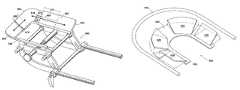
- FIG. 1is perspective drawing of a cushion and support structure for one embodiment of the present invention.
- FIG. 2is a perspective drawing illustrating another aspect of the present invention.
- FIG. 3Ais a perspective drawing of an embodiment of an adjustable support plate.
- FIG. 3Bis a bottom view of the support structure illustrated in FIG. 3A .
- FIG. 4illustrates a contour adjustment mechanism for a support plate.
- FIG. 5is a perspective diagram illustrating an occipital relief aspect of the present invention.
- the present inventionis directed towards an adjustable head-support that can be integrated into, or attached to a therapy table.
- One aspect of the present inventionis to provide a head-support that minimizes patient discomfort due to excessive pressure being applied to more sensitive areas of the face. For instance, excessive pressure in the sinus region and cause significant discomfort to a patient.
- Another aspect of the inventionis to provide an adjustable head rest that can easily conform to various facial structures.
- One method for providing this aspect of the present inventionis through utilization of a formed cushion with a substantially rigid support plate.
- the formed cushionoperates to maximize the distribution of the weight of the patient's head.
- the formed cushionis coupled with a substantially rigid plate that enables the shape of the cushion to be further altered individually for a patient.
- Another aspect of the present inventionis to provide a mechanism to relieve pressure to the occipital nerve when the patient is in the supine position.
- Another aspect of the present inventionis the introduction of an attachment to a headrest that can be used to hold aroma therapy oils or liquids in proximity to the patient's breathing passages.
- FIG. 1is perspective drawing of a cushion and support structure for one embodiment of the present invention.
- FIG. 1illustrates two main components, a contoured cushion 100 and a support structure 150 .
- the cushion 100is shown as having a generally U-shape structure however, other configurations are also anticipated including, but not limited to, a squared U or C shape structure, a V-shaped structure, an O-ring or open O-ring, or other similar type structures.
- the shape of the cushion 100is such that it is operable to receive and hold the head of a patient, customer or user.
- the present inventionis not limited to any particular structural shape of the cushion 100 , the present invention will be described as being embodied within a substantially U-shaped structure.
- the cushion 100includes a closed end 102 and an open end 104 .
- the open end 104is proximal to the patient's neck and chin where as the closed portion 102 is distal to the patient's neck and chin.
- the cushion 100includes a bottom surface 105 that is substantially flat when the cushion is in an uncompressed state. It should be appreciated that the bottom surface 105 may also include ridges along the surface that can be used to help maintain the cushion 100 in position when placed on another surface.
- the cushion 100may also include a series of protrusions that are fixedly attached to the cushion and extend below the bottom surface 105 .
- the protrusionscan be used to attach the cushion to a surface and thus, the protrusions may be threaded.
- Other techniquessuch as snaps, buckles or tie strings, as well as others may also be used to secure the cushion 100 to another surface and the present invention is not limited to any particular technique, although some of the listed techniques are considered novel.
- the cushion 100is shown as including two Velcro strips 106 and 108 that are mounted to the bottom surface 105 .
- the cushion 100further includes an outer perimeter surface 110 , an inner perimeter surface 115 and an upper surface 120 .
- the outer perimeter surface 110 and the inner perimeter surface 115are substantially parallel to each other and preferably, the inner height 116 of the inner perimeter surface 115 is less than the outer height 111 of the outer perimeter surface 110 .
- the upper surface 120is substantially flat proximate to the upper edge 112 of the outer perimeter surface 120 where the upper surface 120 adjoins the upper edge 112 of the outer perimeter surface 110 .
- the upper surface 120tapers down to the upper edge 117 of the inner perimeter surface 115 .
- the taper of the upper surface 120can consist of a flat portion 121 and a convex portion 122 as illustrated.
- the upper surfacemay also be substantially flat across the extension from the upper edge 112 of the outer perimeter surface 115 to the upper edge 117 of the inner perimeter surface 115 , may be concave of the entire extension, may be convex over the entire extension or may include a combination of one or more of these configurations. Utilizing two or more of the identified tapers can advantageously maximize the facial contact of the upper surface 120 of the cushion 100 . In addition, it will also be appreciated that similar advantages can be obtained by utilizing different foam densities in different areas of the cushion to help maximize the facial surface that is supported by the cushion.
- FIG. 1also illustrates a perspective diagram of a support structure 150 suitable for receiving the cushion 100 .
- the support structure 150includes a support plate on which the cushion 100 rests.
- the illustrated support plate 152is a rigid or semi-rigid material and includes an upper surface 154 on which the bottom surface 105 of the cushion 100 can rest.
- the surface area of the upper surface 154 of the support plate 152is substantially the same shape as the bottom surface 105 of the cushion 100 .
- the support plate 152is substantially flat for receiving and supporting the bottom surface 105 of the cushion 100 .
- the upper surface of the support platewould include indentions aligned with the ridges of the bottom surface of the cushion.
- the support platewould include holes that align with the protrusions from the bottom surface of the cushion.
- the support platemay include matching buckles or tie downs for other various attachment mechanisms of the cushion.
- the support plate 152includes two Velcro strips 156 and 158 that mate with the Velcro strips 106 and 108 on the bottom surface 105 of the cushion 100 respectively.
- the support plate 152is shown as in a substantially U-shape configuration and is attached to a support rod 160 through a scissor-like support structure that includes a short upper leg 162 and a long lower leg 164 .
- the scissor-like support structureis included on each leg of the U-shaped support plate 152 .
- the support plate 152includes two flanges 166 that depend from the bottom surface of the support plate 152 proximate to the legs. Because the structure used to connect the support plate 152 to the support rod 160 is mirrored for each leg of the support plate 152 , only one side will be described.
- short upper leg 160is connected to the flange 166 on the support plate 152 and the support rod 160 passes through the other end of the short upper leg 162 .
- long lower leg 164is connected to the flange 166 on the support plate 152 and the support rod 160 passes through the other end of the long lower leg 164 .
- Two attachment rods 168are pivotally coupled to opposing ends of the support rod 166 by including a circular sleeve 170 through which the support rod 166 passes.
- the attachment rods 168can he inserted and secured into a receiving slot or sleeve that is included in a therapy table (not shown).
- a stop 172is attached to one end of the support rod 160 and retains the circular sleeve 170 , the short upper leg 162 and the longer lower leg 164 on the support rod 160 .
- a cam assemblyis attached to the end of the support rod 160 opposite to the stop 172 .
- An elongated and flanged sleeve 176is located between the two sets of shorter upper arms 162 , longer lower arms 164 and circular rings 172 and the support rod 160 extends through the elongated and flanged sleeve 176 .
- the cam lever 180 of the cam assembly 174When the cam lever 180 of the cam assembly 174 is moved to the open position (illustrated), the shorter upper legs 162 , longer lower legs 174 and circular sleeves 170 can freely rotate around the support rod 166 .
- the cam lever 180is placed into the closed position (not illustrated) the support rod 166 is pulled thereby forcing the stop 172 and the cam assembly 174 to force a friction onto the shorter upper legs 162 , longer lower legs 174 and circular sleeves 170 there by preventing or restricting the ability to rotate or pivot.
- this structureallows the support plate 152 to be rotated coaxially to the axis of the support rod 166 and to adjust the plane of the support plate 152 .
- the support structure 150may in and of itself include novel and non-obvious elements, other aspects of the present invention are not limited to utilization of the disclosed support structure 150 but rather, the disclosed support structure 150 is provided to illustrate a preferred embodiment of the various aspects of the present invention.
- FIG. 1includes a perspective diagram illustrating a potion holder structure 190 for aroma therapy elements or potions.
- the potion holder structure 190is adjustably or fixedly attached to the support structure 150 .
- the potion holder structure 190can be attached to various locations on the support structure 150 .
- the potion holder structurecan be located approximately half-way between the closed end and the open end of the U-shaped support plate 152 and extend from the left side of the support plate 152 to the right side of the support plate 152 .
- the potion holderincludes a cup, bowl or tray 191 that can hold various aroma therapy elements including oils, liquids, beads, flakes, herbs, potions or the like.
- the potion holderis adjustable so that the cup 191 can be placed in close proximity to the nose of the patient or retracted away from the patient's nose as desired.
- the illustrated embodimentshows an integrated holder that is suitably positioned in a manner to allow aroma from the aroma therapy elements to enter into the breathing intake area of a user resting their face the cushion 100 in a prone or kneeling position.
- the cup 191is integrally formed with two protruding arms 192 and 193 .
- the protruding arms 192 and 193are pivotally adjoined to adjustment swing arms 194 and 195 respectively.
- the adjustment swing arms 194 and 195are then pivotally adjoined to the support structure 150 .
- the swing arms 194 and 195are connected to the long lower leg 164 ; however, it will be appreciated that they could also be attached to the short upper leg 162 or to the support plate 152 .
- the cup 191hangs below the support plate 152 , most preferably in front of a patient's face once the face is placed onto the cushion 100 .
- the patientcan move the cup 191 to a position that provides a desired intensity of aroma.
- the cup 191may be fixedly attached to the support structure 150 so that the cup 191 maintains a constant position relative to the support structure 150 .
- potion holder structure 190Other configurations of the potion holder structure 190 are also anticipated, such as, a non-adjustable holder, a holder that only attaches to the support plate at one point, a malleable arm with a cup 191 located on the end, a telescoping arm or the like.
- the present inventionanticipates various embodiments and the present invention should not be limited to any particular embodiment.
- the novel characteristic of this aspect of the present inventionis the inclusion of a holder for aroma therapy potions in such a manner that the patient can enjoy aroma from a potion that is inserted into a holder that is integrated or attached to the head rest.
- FIG. 2is a perspective drawing illustrating another aspect of the present invention.
- the illustrated embodimentshows a cushion 200 and a support structure 250 .
- the support structure 250includes a support plate 252 .
- the support plate 252includes an upper surface 254 for receiving the bottom surface 205 of cushion 200 .
- the upper surface 254 of support plate 252is contoured. In the illustrated embodiment, the contour of the upper surface 254 is substantially convex.
- the upper surfaceincludes an outer edge 256 and an inner edge 258 .
- the outer edge 256is higher than the inner edge 258 .
- the convex surface of the upper surface 254tapers down from the outer edge 256 to the inner edge 258 .
- this aspect of the present inventioncauses the cushion 200 to be deformed in a manner so that the upper surface 220 of the cushion 200 will come in contact with a larger area of a face being placed onto the upper surface 220 of the cushion 200 and thus, more effectively distribute the weight. This is accomplished because the upper surface of the cushion 200 is forced to be in closer proximity to the shape of a face.
- this aspect of the inventionis illustrated as receiving a cushion 200 that has a substantially rectangular cross-section, the cushion presented in FIG. 1 and variations thereof can equally be utilized in this embodiment of the present invention.
- One of the advantages to this aspect of the present inventionis that by utilizing a contoured support plate 252 , a cushion can be forced into a shape that is more suitable for receiving a subject's face.
- the upper surface 254 of the support plate 252does not necessarily have to be convex.
- the upper surfacecan be flat and sloped, concave, or a combination of any two or more of these surface types.
- FIG. 3Ais a perspective drawing of an embodiment of an adjustable support plate.
- the support plate 352is constructed of several components that can be used to adjust the length and width of the support plate 352 .
- the adjustments to the support plate 352result in a compression or expansion of the cushion, thereby allowing the cushion to be formed to various facial structures.
- the illustrated support plate 352includes four components: a left-chin proximal plate 360 , a right-chin proximal plate 362 , a left-forehead proximal plate 364 and a right-forehead proximal plate 366 .
- the interconnected platescan be attached to each other using a variety of techniques that are well known in the art and will be readily apparent. For purposes of understanding the operation of the invention, a particular embodiment is being illustrated.
- the components of the support plate 353are slideably connected to each other. At the joints of the various plates, one plate has a slightly smaller width than the other plate.
- the wider platemay include an integral sleeve that receives the narrower plate or may be hollow, thereby receiving the narrow portion of the plate.
- the left-forehead proximal plate 364has a small width than the right-forehead proximal plate 366 .
- the left-forehead proximal plate 364slides into a hollow opening 370 in the right-forehead proximal plate 366 .
- the joint 372 between the right-chin proximal plate 362 and the right-forehead proximal plate 366is illustrated using another potential configuration.
- a tongue and groove type structureis illustrated.
- the right finger 374 and the left finger 376form a groove 378 in the right-forehead proximal plate 366 .
- the groove 378slideably engages a tongue 380 integrated into the right-chin proximal plate 362 .
- the right-forehead proximal plate 366slides along the lower surface of the right-chin proximal plate 362 rather than being inserted through a hollow opening in the right-chin proximal plate 362 .
- joint 368 and joint 372are simply two illustrations of how the present invention can be implemented and are not intended to limit the present invention to any particular structure. Rather, this inventive aspect of the present invention includes the ability to adjust the width and the length of the support plate 352 and thereby, allow the support plate to compress or expand an attached cushion to conform to various facial structures.
- FIG. 3Bis a bottom view of the support structure illustrated in FIG. 3A .
- a mechanism for actuating the adjustment of the support plate 352is illustrated.
- the width 390 of the support plate 352is adjusted by actuating an adjustment assembly 340 .
- the illustrated adjustment assemblyincludes a threaded shaft 342 and a threaded sleeve 344 .
- the threaded shaft 342extends through flange 346 , which is fixedly attached to the bottom surface of right-chin proximal plate 366 .
- a knob 322is integrally formed or fixedly attached to an unthreaded end of threaded shaft 342 .
- the threaded shaft 342extends through the flange 346 in such a manner the threaded screw 342 is free to turn in response to rotating the knob 352 .
- the threaded portion of threaded shaft 342is inserted into the opening 324 of threaded sleeve 344 .
- the threaded sleeve 344is fixedly coupled to a flange 325 , which is fixedly attached to the bottom surface of the left-chin proximal plate 360 .
- the adjustment knob 322is turned in one direction, the threaded screw 342 penetrates into the threaded sleeve 344 .
- the outer washer 349engages the outside surface of the flange 346 thereby encouraging the right-forehead proximal plate 366 to move towards the left-forehead proximal plate 364 thereby decreasing the width 390 of the support plate 352 .
- Alternate embodimentsinclude, but are not limited to, (a) providing serrated edges that allow the plates to be slid in and out with force but will be held in place at the absence of such force (b) providing a clamping lever to secure the various plates into position, (c) providing tightening wing nut screws to secure the plates in position.
- the supporting plate 352includes both width 390 and length 392 adjustments, other embodiments may only include one of the two available adjustments.
- the embodiment illustrated in FIGS. 3A–Ballow the support structure 350 to adjust the width 390 and the length 392 of the support plate 352 .
- a cushionsuch as cushion 100 or cushion 200 is attached to the support plate 352
- the cushionwill be either compressed or stretched in conformance with the adjustments to the support plate 352 .
- the support platewill include at least two interconnected plates: a left plate and a right plate.
- the interconnected platescan be attached to each other using a variety of techniques but in the preferred embodiment, the plates are slideably connected to each other.
- the wider platemay include an integral sleeve or bowed flanges that receive the narrower plate.
- the bowed flangesare attached to the edges of a common surface of the receiving plate and are configured in such a manner to receive the end portion of the sliding plate. It should be appreciated that multiple sets of the bowed flanges can be utilized to provide additional structural support and the receiving plate can be either the left plate or the right plate.
- the ends of the sliding platemay include a stop to prevent the sliding plate from being fully retracted from the bowed flanges of the receiving plate.
- FIG. 4illustrates a contour adjustment mechanism for a support plate.
- the support plate 452includes one or more adjusting flaps 420 that can be used to adjust the contour of the support plate 452 .
- Each of the adjusting flaps 420are hinged to the main body 422 of the support plate 452 in a restrictive manner that allows a force applied to the adjustable flap 420 to cause the adjustable flap 420 to move away from the force and when the force is released, to maintain the new position, even in the presence of a slight force.
- the adjusting flaps 420can be used to alter the overall shape of the upper surface 454 of the support plate 452 . Similar to the embodiment illustrated in FIG.
- the support plate 452alters the configuration of a cushion that is placed onto the upper surface 454 of the support plate 452 .
- a cushion placed on the upper surface 454will be compressed so that the inner portion of the cushion will be drawn down and away from the face and the upper portion of the cushion will be drawn up towards the face. This action results in creating more contact between the subjects face and the cushion.
- This compression of the cushionresults in modifying the contour of the upper surface of the cushion.
- this aspect of the present inventionallows the upper surface of the cushion to be adjusted for various facial structures.
- the flaps 420can be set to a variety of settings thereby providing great flexibility in the adjustment of the cushion.
- a piping 456can be used as to secure the flaps 420 to a desired setting.
- the support platecan be constructed of a malleable material that can be deformed by the application of a force but that is rigid enough to maintain its shape under normal operating conditions (i.e., in supporting a patient's head).
- a malleable materialcan include various aluminum alloys or lead based metals as are commonly found in medical devices such as removable casts and splints.
- this embodiment of the inventionallows the support plate to be adjusted in a variety of manners. Each of the adjustments to the support plate equate with compressions or expansions of the cushion attached to the support plate. Thus, the upper surface of the cushion can be infinitely adjusted to fit the contours of any facial structure.
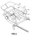
- FIG. 5is a perspective diagram illustrating an occipital relief aspect of the present invention.
- the present inventionutilizes a finger protrusion that is attached to the support plate and operates to relieve pressure to the occipital nerve.
- a flap 510is pivotally attached to the edge of the support plate 552 .
- One side of the flap 510includes a finger protrusion 512 .
- the finger protrusion 512When the flap is in the open position, the finger protrusion 512 is moved out of the way.
- the finger protrusionsare pivoted into the open position so that they are below the upper surface of the support plate and thus, do not interfere with the patient when the patient places his or her face on the cushion.
- the finger protrusionsare pivoted into the closed position so that the finger protrusion 512 extends vertically from the upper surface 554 of the support plate 552 and can engage the occipital nerve of the patient.
- a finger protrusion that can be slid onto the support plate 552a finger protrusion that can be snapped onto the support plate 552 , a support plate overlay that can be laid over the top of the support plate 552 , the overlay including integrally formed finger protrusions.
- the finger protrusion for each side of the support platecan be integrated into a single flap or unit.
- Other embodiments of this aspect of the present inventionare also anticipated and the disclosed embodiments are not intended to limit this aspect of the present invention in any manner.
- the present inventionhas been described using detailed descriptions of embodiments thereof that are provided by way of example and are not intended to limit the scope of the invention.
- the present inventioncan be implemented as a process that runs within a variety of system environments or as an entire system including various components.
- the described embodimentscomprise different features, not all of which are required in all embodiments of the invention.
- Some embodiments of the present inventionutilize only some of the features, aspects or possible combinations of the features or aspects. Variations of embodiments of the present invention that are described and embodiments of the present invention comprising different combinations of features noted in the described embodiments will occur to persons of the art.
Landscapes
- Health & Medical Sciences (AREA)
- Engineering & Computer Science (AREA)
- Biomedical Technology (AREA)
- Life Sciences & Earth Sciences (AREA)
- Animal Behavior & Ethology (AREA)
- General Health & Medical Sciences (AREA)
- Public Health (AREA)
- Veterinary Medicine (AREA)
- Neurosurgery (AREA)
- Otolaryngology (AREA)
- Orthopedics, Nursing, And Contraception (AREA)
Abstract
Description
Claims (22)
Priority Applications (3)
| Application Number | Priority Date | Filing Date | Title |
|---|---|---|---|
| US10/942,299US7080420B2 (en) | 2004-09-16 | 2004-09-16 | Adjustable head-support for therapy tables |
| PCT/US2004/030933WO2006041436A1 (en) | 2004-09-16 | 2004-09-22 | Adjustable head-support for therapy tables |
| US11/450,845US7424759B2 (en) | 2004-09-16 | 2006-06-09 | Adjustable head-support for therapy tables |
Applications Claiming Priority (1)
| Application Number | Priority Date | Filing Date | Title |
|---|---|---|---|
| US10/942,299US7080420B2 (en) | 2004-09-16 | 2004-09-16 | Adjustable head-support for therapy tables |
Related Child Applications (1)
| Application Number | Title | Priority Date | Filing Date |
|---|---|---|---|
| US11/450,845ContinuationUS7424759B2 (en) | 2004-09-16 | 2006-06-09 | Adjustable head-support for therapy tables |
Publications (2)
| Publication Number | Publication Date |
|---|---|
| US20060053557A1 US20060053557A1 (en) | 2006-03-16 |
| US7080420B2true US7080420B2 (en) | 2006-07-25 |
Family
ID=36032245
Family Applications (2)
| Application Number | Title | Priority Date | Filing Date |
|---|---|---|---|
| US10/942,299Expired - LifetimeUS7080420B2 (en) | 2004-09-16 | 2004-09-16 | Adjustable head-support for therapy tables |
| US11/450,845Expired - LifetimeUS7424759B2 (en) | 2004-09-16 | 2006-06-09 | Adjustable head-support for therapy tables |
Family Applications After (1)
| Application Number | Title | Priority Date | Filing Date |
|---|---|---|---|
| US11/450,845Expired - LifetimeUS7424759B2 (en) | 2004-09-16 | 2006-06-09 | Adjustable head-support for therapy tables |
Country Status (2)
| Country | Link |
|---|---|
| US (2) | US7080420B2 (en) |
| WO (1) | WO2006041436A1 (en) |
Cited By (20)
| Publication number | Priority date | Publication date | Assignee | Title |
|---|---|---|---|---|
| US20060288484A1 (en)* | 2005-06-14 | 2006-12-28 | Roleder Jon W | Headrest assembly with improved adjustability for a massage device |
| US20080047069A1 (en)* | 2006-08-23 | 2008-02-28 | Kimberly Forness Wilson | Face cradle insert device |
| US20080047070A1 (en)* | 2006-08-23 | 2008-02-28 | Kimberly Forness Wilson | Face Cradle Insert Device |
| US20080289110A1 (en)* | 2007-05-25 | 2008-11-27 | Duterte Jr Ramon R | Inflatable travel aid |
| US20100201176A1 (en)* | 2009-02-11 | 2010-08-12 | Dental Equipment, Llc, Dba Pelton & Crane | Biarticulated headrest for chair |
| US20110004048A1 (en)* | 2009-07-03 | 2011-01-06 | Henry Brunelle | Therapy devices and domestic/commercial therapy system |
| US20110035882A1 (en)* | 2009-08-17 | 2011-02-17 | Lijun Wang | Medical head restraint and medical bed system using the same |
| US20130232696A1 (en)* | 2012-03-11 | 2013-09-12 | Henry M. Halimi | Portable personal support |
| US20130305455A1 (en)* | 2012-05-17 | 2013-11-21 | Mercy Medical Research Institute | Prone positioning device |
| USD704828S1 (en)* | 2013-02-04 | 2014-05-13 | Ying-Ling Lin | Medical pillow seat |
| US8898840B1 (en) | 2011-10-28 | 2014-12-02 | Michael S. Majette | Head and neck support device |
| US20160151221A1 (en)* | 2014-11-28 | 2016-06-02 | Mary Madeline Mount | Head support device |
| CN107625604A (en)* | 2017-09-26 | 2018-01-26 | 南京晶云化工有限公司 | Operating desk for head operation |
| US10034563B2 (en) | 2016-09-15 | 2018-07-31 | Joan Mary Held | Portable head support |
| USD826410S1 (en)* | 2016-09-02 | 2018-08-21 | Optimedica Corporation | Headrest for mobile patient bed |
| USD837385S1 (en)* | 2016-09-20 | 2019-01-01 | Siemens Healthcare Gmbh | Head holder for patient table |
| US10814147B2 (en) | 2014-06-13 | 2020-10-27 | University Of Utah Research Foundation | Therapeutic ultrasound breast treatment |
| USD921398S1 (en) | 2019-11-15 | 2021-06-08 | Michael S. Majette | Head and neck support device |
| US12201564B1 (en) | 2022-11-28 | 2025-01-21 | Earthlite, Llc | Treatment device with adjustable support capabilities |
| US12208042B2 (en) | 2021-09-29 | 2025-01-28 | Stryker Corporation | Patient transport apparatus having an extender for a head deck section |
Families Citing this family (25)
| Publication number | Priority date | Publication date | Assignee | Title |
|---|---|---|---|---|
| US7448686B2 (en)* | 2004-11-01 | 2008-11-11 | Nelson Mark Hersh | Dental chair headrest |
| USD603967S1 (en)* | 2007-12-21 | 2009-11-10 | Wake Forest University Health Sciences | Surgical head support adapter |
| US8191553B2 (en) | 2008-06-30 | 2012-06-05 | Randal Haworth | Jaw thrust device |
| US20100263125A1 (en)* | 2008-10-16 | 2010-10-21 | Roleder Jonathan W | Embedded headrest assembly for a massage table |
| US8549683B2 (en)* | 2012-02-10 | 2013-10-08 | Mercury Enterprises, Inc. | Surgical head support |
| GB2504463B (en)* | 2012-06-20 | 2017-02-08 | Specialised Orthotic Services Ltd | Support product |
| USD718074S1 (en) | 2012-11-23 | 2014-11-25 | Sami Tuomas Savolainen | Pillow |
| AU350422S (en)* | 2013-05-30 | 2013-08-27 | Riambel Pty Ltd | Head support |
| USD764063S1 (en)* | 2013-11-19 | 2016-08-16 | Merivaara Oy | Medical equipment subcomponent |
| USD780929S1 (en)* | 2013-11-19 | 2017-03-07 | Merivaara Oy | Medical equipment component |
| EP3182950A4 (en)* | 2014-08-22 | 2018-03-21 | Shanghai Xintang Industrial Co., Ltd | Cradle frame and structure |
| EP3182857A4 (en) | 2014-08-22 | 2018-03-28 | Shanghai Xintang Industrial Co., Ltd | Hinge member and foldable structure incorporating the same |
| KR20170053672A (en)* | 2014-09-05 | 2017-05-16 | 더 에르고 베이비 캐리어 아이엔씨 | Nursing pillow |
| US9867749B2 (en)* | 2015-05-18 | 2018-01-16 | Matthew Mitchell | Facial cradle |
| USD851259S1 (en) | 2015-05-18 | 2019-06-11 | Matthew Mitchell | Face cradle |
| DE102017127177A1 (en)* | 2017-11-17 | 2019-05-23 | MAQUET GmbH | One-handed adjustable head plate for an operating table |
| EP3590486A1 (en)* | 2018-07-04 | 2020-01-08 | Enraf Nonius B.V. | Treatment bed |
| CN109806097A (en)* | 2019-03-21 | 2019-05-28 | 莒县人民医院 | A kind of neurosurgery head fixing device |
| US11759022B2 (en) | 2020-07-07 | 2023-09-19 | Anna Mace | Face hammock |
| CN112022565B (en)* | 2020-10-09 | 2021-07-02 | 茂名市人民医院 | Head fixing device for ophthalmic therapy |
| US12414887B2 (en)* | 2020-10-23 | 2025-09-16 | Hill-Rom Services, Inc. | Proning frame for a patient bed |
| USD955586S1 (en)* | 2021-03-25 | 2022-06-21 | Waleed A. Belleh | Adjustable travel pillow support |
| US20240138576A1 (en)* | 2022-11-01 | 2024-05-02 | Michael Straub | Modular freestanding face down neck pillow system for lie-flat seating |
| GB2627996A (en)* | 2023-03-10 | 2024-09-11 | Haslam Kathryn | Shape-adjustable headrest |
| US12207749B1 (en)* | 2024-04-01 | 2025-01-28 | Kristine Saad | Techniques for lying prone comfortably |
Citations (37)
| Publication number | Priority date | Publication date | Assignee | Title |
|---|---|---|---|---|
| US2239003A (en) | 1939-07-18 | 1941-04-22 | Samuel R Jones | Headrest |
| US2461434A (en) | 1944-05-24 | 1949-02-08 | Moyers Eunice | Folding mechanical pillow |
| GB638046A (en)* | 1948-06-02 | 1950-05-31 | Francis Cecil Holton | Improvements in or relating to pillows, head rests and the like, especially for infants |
| US2688142A (en) | 1952-06-05 | 1954-09-07 | Elmer V Jensen | Headrest |
| US3289224A (en)* | 1964-08-17 | 1966-12-06 | Arnold D Witchel | Contour cushion lounge |
| US3315282A (en) | 1965-06-08 | 1967-04-25 | Lowery Andrew | Headrest for cosmetic use and the like |
| US3337883A (en)* | 1965-10-22 | 1967-08-29 | Allison John Duncan | Head rest |
| US4504050A (en) | 1982-09-30 | 1985-03-12 | Duke University | Head support |
| US4531247A (en) | 1982-09-28 | 1985-07-30 | Eary Sr George D | Adjustable upper body rest |
| US5165137A (en) | 1992-06-22 | 1992-11-24 | The United States Of America As Represented By The Secretary Of The Army | Head support stand adjustable by compound turnbuckle |
| US5177823A (en) | 1992-05-13 | 1993-01-12 | Oakworks, Inc. | Adjustable headrest |
| US5214815A (en) | 1992-08-28 | 1993-06-01 | Codman & Shurtleff, Inc. | Surgical headrest with removable foam pad |
| US5287576A (en) | 1993-02-08 | 1994-02-22 | Fraser Lance G | Head support |
| US5347668A (en)* | 1993-10-04 | 1994-09-20 | Manning Duane B | Therapeutic headrest device |
| US5427436A (en) | 1994-05-26 | 1995-06-27 | Lloyd; John T. | Adjustable headrest |
| US5546619A (en) | 1995-01-05 | 1996-08-20 | Braun; Mary J. | Head supporting device for use while suntanning |
| US5613501A (en) | 1993-06-10 | 1997-03-25 | Gary K. Michelson | Surgical face support |
| US5615432A (en) | 1995-06-07 | 1997-04-01 | Von Ohlen, Iii; Thomas F. | Head and neck support device |
| JPH10117905A (en) | 1996-10-18 | 1998-05-12 | Tsuyoshi Yamanaka | Pillow for lying prone |
| EP0880925A1 (en) | 1997-05-30 | 1998-12-02 | Robert Plastre | Multiposition anatomic pillow |
| US5970546A (en) | 1998-02-26 | 1999-10-26 | Paul Shalita | Portable headrest having a base support member with air passages for use while sunbathing |
| US6023801A (en) | 1998-02-26 | 2000-02-15 | Lamm; Kenneth | Therapeutic headrest |
| US6049926A (en) | 1997-04-30 | 2000-04-18 | Amaral; Manuel G. | Head cradle for a therapy table |
| JP2000126016A (en) | 1998-10-22 | 2000-05-09 | Senko Medical Instr Mfg Co Ltd | Pillow for prone position |
| JP2000139655A (en) | 1998-11-17 | 2000-05-23 | Yahatagumi:Kk | Pillow |
| US6273865B1 (en) | 1999-07-12 | 2001-08-14 | Naomi Perez | Massage therapy chair |
| DE10038117A1 (en) | 2000-02-09 | 2001-08-30 | Marion Brust | Floor and couch cushion for preventing and relieving bedsores has a rubber-like outer casing filled with a gel and is flat in the region of the thigh and the spinal column |
| US6374441B1 (en) | 2000-02-22 | 2002-04-23 | Suzanne Begell | Headrest for chiropractor's table |
| US6397414B1 (en) | 2000-06-21 | 2002-06-04 | John T. Lloyd | Adjustable face rest |
| US20020096929A1 (en) | 2001-01-23 | 2002-07-25 | Chris Showerman | Portable massage chair converter |
| US6460207B1 (en)* | 1998-10-13 | 2002-10-08 | Cleveland Clinic Foundation | Anti-SIDS pediatric headrest |
| US20020184706A1 (en) | 2001-06-06 | 2002-12-12 | Oakworks, Inc. | Support device |
| US6532609B2 (en) | 2000-08-30 | 2003-03-18 | Gainsborough Accessories International Limited | Physiotherapy bench |
| US20030051293A1 (en) | 2000-09-27 | 2003-03-20 | Chapman Paul William | Flexible head support |
| US6658681B2 (en)* | 2002-04-19 | 2003-12-09 | The First Years, Inc. | Positionable pillow |
| US20040045087A1 (en)* | 2002-08-23 | 2004-03-11 | Morris Michele Maria | Formative pillow with flexible spine |
| US20040172064A1 (en)* | 2003-02-27 | 2004-09-02 | Macdonald Bonnie | Treatment table with an aroma dispenser |
Family Cites Families (14)
| Publication number | Priority date | Publication date | Assignee | Title |
|---|---|---|---|---|
| US1915944A (en)* | 1931-04-16 | 1933-06-27 | Robert Forgie Hunter | Projection screen |
| US4019727A (en)* | 1975-11-20 | 1977-04-26 | Case Western Reserve University | Head support and restraining apparatus |
| US4752064A (en)* | 1987-03-23 | 1988-06-21 | Gene Voss | Therapeutic head support |
| SE9002448L (en)* | 1990-07-17 | 1992-01-18 | Ata Byy Markprod Ab | MARKING AND INFORMATION BOARD DEVICE |
| US5408713A (en)* | 1993-08-16 | 1995-04-25 | Westcoast Med-Assist, Inc. | Head-rest |
| US5706130A (en)* | 1995-10-30 | 1998-01-06 | Rosen; John B. | Support assembly for a retractable device |
| US6038720A (en)* | 1996-01-24 | 2000-03-21 | Camp Kazoo, Ltd. | Attachment for a support pillow and methods for its use |
| US5904659A (en)* | 1997-02-14 | 1999-05-18 | Exogen, Inc. | Ultrasonic treatment for wounds |
| JP3385207B2 (en)* | 1997-09-05 | 2003-03-10 | 泉株式会社 | Portable screen |
| US6151734A (en)* | 1998-01-21 | 2000-11-28 | Lawrie; William H. | Head support apparatus |
| US6490737B1 (en)* | 1998-05-19 | 2002-12-10 | Dupaco, Inc | Protective cushion and cooperatively engageable helmet casing for anesthetized patient |
| US6191886B1 (en)* | 1998-08-24 | 2001-02-20 | Vutec Corp. | Video projection screen assembly |
| US5946749A (en)* | 1998-10-22 | 1999-09-07 | Sewell; Cheryl H. | Comfort lounge chair |
| USD456516S1 (en)* | 2001-04-13 | 2002-04-30 | Myron Cheshaek | Padded face rest |
- 2004
- 2004-09-16USUS10/942,299patent/US7080420B2/ennot_activeExpired - Lifetime
- 2004-09-22WOPCT/US2004/030933patent/WO2006041436A1/enactiveApplication Filing
- 2006
- 2006-06-09USUS11/450,845patent/US7424759B2/ennot_activeExpired - Lifetime
Patent Citations (37)
| Publication number | Priority date | Publication date | Assignee | Title |
|---|---|---|---|---|
| US2239003A (en) | 1939-07-18 | 1941-04-22 | Samuel R Jones | Headrest |
| US2461434A (en) | 1944-05-24 | 1949-02-08 | Moyers Eunice | Folding mechanical pillow |
| GB638046A (en)* | 1948-06-02 | 1950-05-31 | Francis Cecil Holton | Improvements in or relating to pillows, head rests and the like, especially for infants |
| US2688142A (en) | 1952-06-05 | 1954-09-07 | Elmer V Jensen | Headrest |
| US3289224A (en)* | 1964-08-17 | 1966-12-06 | Arnold D Witchel | Contour cushion lounge |
| US3315282A (en) | 1965-06-08 | 1967-04-25 | Lowery Andrew | Headrest for cosmetic use and the like |
| US3337883A (en)* | 1965-10-22 | 1967-08-29 | Allison John Duncan | Head rest |
| US4531247A (en) | 1982-09-28 | 1985-07-30 | Eary Sr George D | Adjustable upper body rest |
| US4504050A (en) | 1982-09-30 | 1985-03-12 | Duke University | Head support |
| US5177823A (en) | 1992-05-13 | 1993-01-12 | Oakworks, Inc. | Adjustable headrest |
| US5165137A (en) | 1992-06-22 | 1992-11-24 | The United States Of America As Represented By The Secretary Of The Army | Head support stand adjustable by compound turnbuckle |
| US5214815A (en) | 1992-08-28 | 1993-06-01 | Codman & Shurtleff, Inc. | Surgical headrest with removable foam pad |
| US5287576A (en) | 1993-02-08 | 1994-02-22 | Fraser Lance G | Head support |
| US5613501A (en) | 1993-06-10 | 1997-03-25 | Gary K. Michelson | Surgical face support |
| US5347668A (en)* | 1993-10-04 | 1994-09-20 | Manning Duane B | Therapeutic headrest device |
| US5427436A (en) | 1994-05-26 | 1995-06-27 | Lloyd; John T. | Adjustable headrest |
| US5546619A (en) | 1995-01-05 | 1996-08-20 | Braun; Mary J. | Head supporting device for use while suntanning |
| US5615432A (en) | 1995-06-07 | 1997-04-01 | Von Ohlen, Iii; Thomas F. | Head and neck support device |
| JPH10117905A (en) | 1996-10-18 | 1998-05-12 | Tsuyoshi Yamanaka | Pillow for lying prone |
| US6049926A (en) | 1997-04-30 | 2000-04-18 | Amaral; Manuel G. | Head cradle for a therapy table |
| EP0880925A1 (en) | 1997-05-30 | 1998-12-02 | Robert Plastre | Multiposition anatomic pillow |
| US5970546A (en) | 1998-02-26 | 1999-10-26 | Paul Shalita | Portable headrest having a base support member with air passages for use while sunbathing |
| US6023801A (en) | 1998-02-26 | 2000-02-15 | Lamm; Kenneth | Therapeutic headrest |
| US6460207B1 (en)* | 1998-10-13 | 2002-10-08 | Cleveland Clinic Foundation | Anti-SIDS pediatric headrest |
| JP2000126016A (en) | 1998-10-22 | 2000-05-09 | Senko Medical Instr Mfg Co Ltd | Pillow for prone position |
| JP2000139655A (en) | 1998-11-17 | 2000-05-23 | Yahatagumi:Kk | Pillow |
| US6273865B1 (en) | 1999-07-12 | 2001-08-14 | Naomi Perez | Massage therapy chair |
| DE10038117A1 (en) | 2000-02-09 | 2001-08-30 | Marion Brust | Floor and couch cushion for preventing and relieving bedsores has a rubber-like outer casing filled with a gel and is flat in the region of the thigh and the spinal column |
| US6374441B1 (en) | 2000-02-22 | 2002-04-23 | Suzanne Begell | Headrest for chiropractor's table |
| US6397414B1 (en) | 2000-06-21 | 2002-06-04 | John T. Lloyd | Adjustable face rest |
| US6532609B2 (en) | 2000-08-30 | 2003-03-18 | Gainsborough Accessories International Limited | Physiotherapy bench |
| US20030051293A1 (en) | 2000-09-27 | 2003-03-20 | Chapman Paul William | Flexible head support |
| US20020096929A1 (en) | 2001-01-23 | 2002-07-25 | Chris Showerman | Portable massage chair converter |
| US20020184706A1 (en) | 2001-06-06 | 2002-12-12 | Oakworks, Inc. | Support device |
| US6658681B2 (en)* | 2002-04-19 | 2003-12-09 | The First Years, Inc. | Positionable pillow |
| US20040045087A1 (en)* | 2002-08-23 | 2004-03-11 | Morris Michele Maria | Formative pillow with flexible spine |
| US20040172064A1 (en)* | 2003-02-27 | 2004-09-02 | Macdonald Bonnie | Treatment table with an aroma dispenser |
Cited By (37)
| Publication number | Priority date | Publication date | Assignee | Title |
|---|---|---|---|---|
| US7610639B2 (en)* | 2005-06-14 | 2009-11-03 | Earthlite Massage Tables, Inc. | Headrest assembly with improved adjustability for a massage device |
| US20060290194A1 (en)* | 2005-06-14 | 2006-12-28 | Roleder Jon W | Flexible headrest assembly with non-skid contact for a massage device |
| US20060290195A1 (en)* | 2005-06-14 | 2006-12-28 | Roleder Jon W | Headrest assembly for a massage device |
| US20060290193A1 (en)* | 2005-06-14 | 2006-12-28 | Roleder Jon W | Headrest assembly with improved flexibility for a massage device |
| US20060288487A1 (en)* | 2005-06-14 | 2006-12-28 | Roleder Jon W | Headrest assembly for a massage device with timed support arms and arm connector near the forehead |
| US7979934B2 (en) | 2005-06-14 | 2011-07-19 | Earthlite Massage Tables, Inc. | Headrest assembly for a massage device with timed support arms and arm connector near the forehead |
| US7979933B2 (en)* | 2005-06-14 | 2011-07-19 | Earthlite Massage Tables, Inc. | Headrest assembly with improved flexibility for a massage device |
| US7640609B2 (en)* | 2005-06-14 | 2010-01-05 | Earthlite Massage Tables, Inc. | Headrest assembly for a massage device |
| WO2006138298A3 (en)* | 2005-06-14 | 2009-05-07 | Earthlite Massage Tables Inc | Headrest assembly for a massage device |
| US20060288484A1 (en)* | 2005-06-14 | 2006-12-28 | Roleder Jon W | Headrest assembly with improved adjustability for a massage device |
| US7636968B2 (en) | 2005-06-14 | 2009-12-29 | Earthlite Massage Tables, Inc. | Flexible headrest assembly with non-skid contact for a massage device |
| US7543345B2 (en)* | 2006-08-23 | 2009-06-09 | Kimberly Forness Wilson | Face cradle insert device |
| US20080047070A1 (en)* | 2006-08-23 | 2008-02-28 | Kimberly Forness Wilson | Face Cradle Insert Device |
| US20080047069A1 (en)* | 2006-08-23 | 2008-02-28 | Kimberly Forness Wilson | Face cradle insert device |
| US7574759B2 (en)* | 2006-08-23 | 2009-08-18 | Kimberly Forness Wilson | Face cradle insert device |
| US20080289110A1 (en)* | 2007-05-25 | 2008-11-27 | Duterte Jr Ramon R | Inflatable travel aid |
| US20100201176A1 (en)* | 2009-02-11 | 2010-08-12 | Dental Equipment, Llc, Dba Pelton & Crane | Biarticulated headrest for chair |
| US7871130B2 (en)* | 2009-02-11 | 2011-01-18 | Dental Equipment, Llc | Biarticulated headrest for chair |
| US20110004048A1 (en)* | 2009-07-03 | 2011-01-06 | Henry Brunelle | Therapy devices and domestic/commercial therapy system |
| US20110035882A1 (en)* | 2009-08-17 | 2011-02-17 | Lijun Wang | Medical head restraint and medical bed system using the same |
| US9254235B2 (en)* | 2009-08-17 | 2016-02-09 | Kabushiki Kaisha Toshiba | Medical head restraint and medical bed system using the same |
| US8898840B1 (en) | 2011-10-28 | 2014-12-02 | Michael S. Majette | Head and neck support device |
| US9226587B2 (en)* | 2012-03-11 | 2016-01-05 | Henry M. Halimi | Portable personal support |
| US20130232696A1 (en)* | 2012-03-11 | 2013-09-12 | Henry M. Halimi | Portable personal support |
| US20130305455A1 (en)* | 2012-05-17 | 2013-11-21 | Mercy Medical Research Institute | Prone positioning device |
| US9308147B2 (en)* | 2012-05-17 | 2016-04-12 | Mercy Medical Research Institute | Prone positioning device |
| USD704828S1 (en)* | 2013-02-04 | 2014-05-13 | Ying-Ling Lin | Medical pillow seat |
| US10814147B2 (en) | 2014-06-13 | 2020-10-27 | University Of Utah Research Foundation | Therapeutic ultrasound breast treatment |
| US20160151221A1 (en)* | 2014-11-28 | 2016-06-02 | Mary Madeline Mount | Head support device |
| US9782317B2 (en)* | 2014-11-28 | 2017-10-10 | Mary Madeline Mount | Head support device |
| USD826410S1 (en)* | 2016-09-02 | 2018-08-21 | Optimedica Corporation | Headrest for mobile patient bed |
| US10034563B2 (en) | 2016-09-15 | 2018-07-31 | Joan Mary Held | Portable head support |
| USD837385S1 (en)* | 2016-09-20 | 2019-01-01 | Siemens Healthcare Gmbh | Head holder for patient table |
| CN107625604A (en)* | 2017-09-26 | 2018-01-26 | 南京晶云化工有限公司 | Operating desk for head operation |
| USD921398S1 (en) | 2019-11-15 | 2021-06-08 | Michael S. Majette | Head and neck support device |
| US12208042B2 (en) | 2021-09-29 | 2025-01-28 | Stryker Corporation | Patient transport apparatus having an extender for a head deck section |
| US12201564B1 (en) | 2022-11-28 | 2025-01-21 | Earthlite, Llc | Treatment device with adjustable support capabilities |
Also Published As
| Publication number | Publication date |
|---|---|
| US20060053557A1 (en) | 2006-03-16 |
| US7424759B2 (en) | 2008-09-16 |
| US20060225214A1 (en) | 2006-10-12 |
| WO2006041436A1 (en) | 2006-04-20 |
Similar Documents
| Publication | Publication Date | Title |
|---|---|---|
| US7080420B2 (en) | Adjustable head-support for therapy tables | |
| US5347668A (en) | Therapeutic headrest device | |
| US7089613B2 (en) | Flexing head support suspension system | |
| US3601123A (en) | Dynamic cervical support | |
| US5740571A (en) | Foot support apparatus | |
| US5774916A (en) | Ergonomic matrix for back alignment | |
| US20170027800A1 (en) | Spinal Therapy Apparatus | |
| US20010047143A1 (en) | Cervical remodeling collar | |
| US4432108A (en) | Therapeutic leg support | |
| US5438720A (en) | Toe protector and related devices | |
| US4256096A (en) | Mattress assembly for treatment of patients | |
| CN113648124A (en) | Traditional chinese medical science orthopedics splint with stifling nursing function | |
| US20080105266A1 (en) | Therapeutic Massage Ramp | |
| KR101835987B1 (en) | Pillow for preventing neck disc | |
| HU230016B1 (en) | Headrest for massage table | |
| KR20180013135A (en) | Apparatus for chiropractic treatment | |
| JP2000139977A (en) | Lumbago therapeutic chair | |
| US4404966A (en) | Headrest for a chiropractic device | |
| AU2009238320B2 (en) | A Therapeutic Device | |
| US4917363A (en) | Therapeutic headrest | |
| HU214805B (en) | Head- and necksupport | |
| RU222826U1 (en) | Movable kinesitherapy simulator (TCRP) | |
| CN216629050U (en) | Otology local anesthesia operation support frame | |
| JP2858105B2 (en) | Zero position holder | |
| US10849782B1 (en) | Anti-snoring trampoline pillow |
Legal Events
| Date | Code | Title | Description |
|---|---|---|---|
| STCF | Information on status: patent grant | Free format text:PATENTED CASE | |
| AS | Assignment | Owner name:MASSAGE WAREHOUSE, INC., GEORGIA Free format text:ASSIGNMENT OF ASSIGNORS INTEREST;ASSIGNOR:DAMRON, SCOTT;REEL/FRAME:020014/0543 Effective date:20060222 | |
| AS | Assignment | Owner name:SCRIP, INC., ILLINOIS Free format text:MERGER;ASSIGNOR:MASSAGE WAREHOUSE, INC.;REEL/FRAME:020808/0699 Effective date:20071231 | |
| REMI | Maintenance fee reminder mailed | ||
| FPAY | Fee payment | Year of fee payment:4 | |
| SULP | Surcharge for late payment | ||
| FPAY | Fee payment | Year of fee payment:8 | |
| AS | Assignment | Owner name:CITIZENS BANK, NATIONAL ASSOCIATION, MASSACHUSETTS Free format text:SECURITY INTEREST;ASSIGNORS:SCRIP PRODUCTS CORPORATION;ADVANTAGE MEDICAL EQUIPMENT & SUPPLY, INC.;ALLEGRO ENTERPRISES, INC.;AND OTHERS;REEL/FRAME:033400/0580 Effective date:20140718 | |
| AS | Assignment | Owner name:STIFEL BANK & TRUST, AS ADMINISTRATIVE AGENT, ILLI Free format text:SECURITY INTEREST;ASSIGNORS:SCRIP HOLDING CORPORATION;SCRIP PRODUCTS CORPORATION;ADVANTAGE MEDICAL EQUIPMENT & SUPPLY, INC.;AND OTHERS;REEL/FRAME:042816/0512 Effective date:20170623 | |
| AS | Assignment | Owner name:SCRIP PRODUCTS CORPORATION, ILLINOIS Free format text:RELEASE BY SECURED PARTY;ASSIGNOR:CITIZENS BANK, NATIONAL ASSOCIATION;REEL/FRAME:042883/0819 Effective date:20170623 | |
| MAFP | Maintenance fee payment | Free format text:PAYMENT OF MAINTENANCE FEE, 12TH YR, SMALL ENTITY (ORIGINAL EVENT CODE: M2553) Year of fee payment:12 | |
| AS | Assignment | Owner name:CAPITAL SOUTHWEST CORPORATION , AS ADMINISTRATIVE Free format text:SECURITY INTEREST;ASSIGNORS:SCRIP, INC.;ALLEGRO ENTERPRISES, INC.;ADVANTAGE MEDICAL EQUIPMENT & SUPPLY, INC.;AND OTHERS;REEL/FRAME:048745/0264 Effective date:20190321 Owner name:SCRIP HOLDING CORPORATION, ILLINOIS Free format text:RELEASE BY SECURED PARTY;ASSIGNOR:STIFEL BANK & TRUST, AS ADMINISTRATIVE AGENT;REEL/FRAME:048745/0130 Effective date:20190321 Owner name:ALLEGRO ENTERPRISES, INC., ILLINOIS Free format text:RELEASE BY SECURED PARTY;ASSIGNOR:STIFEL BANK & TRUST, AS ADMINISTRATIVE AGENT;REEL/FRAME:048745/0130 Effective date:20190321 Owner name:SCRIP, INC., ILLINOIS Free format text:RELEASE BY SECURED PARTY;ASSIGNOR:STIFEL BANK & TRUST, AS ADMINISTRATIVE AGENT;REEL/FRAME:048745/0130 Effective date:20190321 Owner name:SCRIP PRODUCTS CORPORATION, ILLINOIS Free format text:RELEASE BY SECURED PARTY;ASSIGNOR:STIFEL BANK & TRUST, AS ADMINISTRATIVE AGENT;REEL/FRAME:048745/0130 Effective date:20190321 Owner name:ADVANTAGE MEDICAL EQUIPMENT & SUPPLY, INC., ILLINO Free format text:RELEASE BY SECURED PARTY;ASSIGNOR:STIFEL BANK & TRUST, AS ADMINISTRATIVE AGENT;REEL/FRAME:048745/0130 Effective date:20190321 |