US7079962B2 - Automated utility meter reading system with variable bandwidth receiver - Google Patents
Automated utility meter reading system with variable bandwidth receiverDownload PDFInfo
- Publication number
- US7079962B2 US7079962B2US10/970,738US97073804AUS7079962B2US 7079962 B2US7079962 B2US 7079962B2US 97073804 AUS97073804 AUS 97073804AUS 7079962 B2US7079962 B2US 7079962B2
- Authority
- US
- United States
- Prior art keywords
- data
- segments
- utility meter
- points
- utility
- Prior art date
- Legal status (The legal status is an assumption and is not a legal conclusion. Google has not performed a legal analysis and makes no representation as to the accuracy of the status listed.)
- Expired - Lifetime
Links
- 238000000034methodMethods0.000claimsabstractdescription32
- 238000012545processingMethods0.000claimsdescription14
- 230000009466transformationEffects0.000claimsdescription11
- 238000004891communicationMethods0.000claimsdescription10
- 238000000638solvent extractionMethods0.000claimsdescription10
- 238000013480data collectionMethods0.000claimsdescription5
- 238000005070samplingMethods0.000claimsdescription2
- 238000007792additionMethods0.000claims3
- 238000005192partitionMethods0.000claims3
- 230000001131transforming effectEffects0.000claims3
- 238000007781pre-processingMethods0.000abstractdescription2
- XLYOFNOQVPJJNP-UHFFFAOYSA-NwaterSubstancesOXLYOFNOQVPJJNP-UHFFFAOYSA-N0.000abstractdescription2
- 230000008569processEffects0.000description18
- 230000006870functionEffects0.000description10
- 238000010586diagramMethods0.000description8
- 230000008859changeEffects0.000description2
- 238000005259measurementMethods0.000description2
- 230000004044responseEffects0.000description2
- 230000008901benefitEffects0.000description1
- 230000005540biological transmissionEffects0.000description1
- 230000002153concerted effectEffects0.000description1
- 230000000694effectsEffects0.000description1
- 230000005611electricityEffects0.000description1
- 238000001914filtrationMethods0.000description1
- 238000010438heat treatmentMethods0.000description1
- 230000008676importEffects0.000description1
- 238000012986modificationMethods0.000description1
- 230000004048modificationEffects0.000description1
- 238000012544monitoring processMethods0.000description1
- 238000001228spectrumMethods0.000description1
Images


Classifications
- G—PHYSICS
- G01—MEASURING; TESTING
- G01D—MEASURING NOT SPECIALLY ADAPTED FOR A SPECIFIC VARIABLE; ARRANGEMENTS FOR MEASURING TWO OR MORE VARIABLES NOT COVERED IN A SINGLE OTHER SUBCLASS; TARIFF METERING APPARATUS; MEASURING OR TESTING NOT OTHERWISE PROVIDED FOR
- G01D4/00—Tariff metering apparatus
- G01D4/002—Remote reading of utility meters
- G01D4/006—Remote reading of utility meters to a non-fixed location, i.e. mobile location
- H—ELECTRICITY
- H04—ELECTRIC COMMUNICATION TECHNIQUE
- H04Q—SELECTING
- H04Q9/00—Arrangements in telecontrol or telemetry systems for selectively calling a substation from a main station, in which substation desired apparatus is selected for applying a control signal thereto or for obtaining measured values therefrom
- H—ELECTRICITY
- H04—ELECTRIC COMMUNICATION TECHNIQUE
- H04Q—SELECTING
- H04Q2209/00—Arrangements in telecontrol or telemetry systems
- H04Q2209/50—Arrangements in telecontrol or telemetry systems using a mobile data collecting device, e.g. walk by or drive by
- H—ELECTRICITY
- H04—ELECTRIC COMMUNICATION TECHNIQUE
- H04Q—SELECTING
- H04Q2209/00—Arrangements in telecontrol or telemetry systems
- H04Q2209/60—Arrangements in telecontrol or telemetry systems for transmitting utility meters data, i.e. transmission of data from the reader of the utility meter
- Y—GENERAL TAGGING OF NEW TECHNOLOGICAL DEVELOPMENTS; GENERAL TAGGING OF CROSS-SECTIONAL TECHNOLOGIES SPANNING OVER SEVERAL SECTIONS OF THE IPC; TECHNICAL SUBJECTS COVERED BY FORMER USPC CROSS-REFERENCE ART COLLECTIONS [XRACs] AND DIGESTS
- Y02—TECHNOLOGIES OR APPLICATIONS FOR MITIGATION OR ADAPTATION AGAINST CLIMATE CHANGE
- Y02B—CLIMATE CHANGE MITIGATION TECHNOLOGIES RELATED TO BUILDINGS, e.g. HOUSING, HOUSE APPLIANCES OR RELATED END-USER APPLICATIONS
- Y02B90/00—Enabling technologies or technologies with a potential or indirect contribution to GHG emissions mitigation
- Y02B90/20—Smart grids as enabling technology in buildings sector
- Y—GENERAL TAGGING OF NEW TECHNOLOGICAL DEVELOPMENTS; GENERAL TAGGING OF CROSS-SECTIONAL TECHNOLOGIES SPANNING OVER SEVERAL SECTIONS OF THE IPC; TECHNICAL SUBJECTS COVERED BY FORMER USPC CROSS-REFERENCE ART COLLECTIONS [XRACs] AND DIGESTS
- Y04—INFORMATION OR COMMUNICATION TECHNOLOGIES HAVING AN IMPACT ON OTHER TECHNOLOGY AREAS
- Y04S—SYSTEMS INTEGRATING TECHNOLOGIES RELATED TO POWER NETWORK OPERATION, COMMUNICATION OR INFORMATION TECHNOLOGIES FOR IMPROVING THE ELECTRICAL POWER GENERATION, TRANSMISSION, DISTRIBUTION, MANAGEMENT OR USAGE, i.e. SMART GRIDS
- Y04S20/00—Management or operation of end-user stationary applications or the last stages of power distribution; Controlling, monitoring or operating thereof
- Y04S20/30—Smart metering, e.g. specially adapted for remote reading
Definitions
- the embodiments of the inventionrelate generally to an automated meter reading (AMR) system such as automated utility resource measurements, data collection, and exercise of control and notification, and more particularly to mobile or fixed AMR receivers for monitoring of utility consumption.
- AMRautomated meter reading
- AMRAutomated Meter Reading
- a mobile radio AMR systemconsists of three basic components: an Encoder-Receiver-Transmitter (ERT), a Data Collection Unit (DCU), and AMR Software.
- the ERTis a meter interface device attached to the meter, which either periodically transmits utility consumption data (“bubble-up” ERTs), or receives a “wake up” polling signal or a request for their meter information from a transceiver mounted in a passing vehicle or carried by the meter reader.
- the ERTin response to a wake-up signal, broadcasts the meter number, the meter reading, and other information to the DCU, which is a mobile computer in, for example, the meter reading vehicle.
- the DCUcollects the information from the ERTs for subsequent uploading into the AMR Software system.
- the AMR Softwareinterfaces with the main system and updates the appropriate accounts of the billing system with the new meter readings.
- ERT signalsare not synthesized and drift in frequency due to temperature changes, location of the ERT modules with respect to the other objects, and internal heating and pulling.
- the frequency shiftsin turn, create problems for a narrowband receiver.
- wideband receiversare required to read ERTs, but wideband receivers are more prone to unwanted interference and other problems.
- One of the possible solutions for this problemis to synthesize the ERT signals as wideband signals. However, it is not possible to read a wideband ERT with a narrowband receiver.
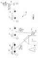
- FIG. 1illustrates the basic elements and processes of a mobile AMR system.
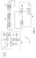
- FIG. 2is a high level schematic diagram of the signal path within a typical AMR system.
- FIG. 3is a schematic diagram of the windowing, partitioning, overlaping, adding, and the FFT processing of the Weighted Overlap-Add (WOLA) method.
- WOLAWeighted Overlap-Add
- FIG. 4is a schematic diagram of an application of four window functions in accordance with an embodiment of the invention.
- FIG. 5is a flow diagram of the proposed method in accordance with an embodiment of the invention.
- Embodiments of the present inventionrelates generally to an AMR system such as automated utility resource measurements, data collection, and exercise of control and notification, and more particularly to AMR receivers that are adjustable to accept signals of different bandwidths.
- AMR systemsuch as automated utility resource measurements, data collection, and exercise of control and notification
- AMR receiversthat are adjustable to accept signals of different bandwidths.
- the embodiments of this inventionkeep the signal processing computational requirements and complexity of the different bandwidths relatively constant. This is done by basic manipulation of the received data prior to Discrete Fourier Transform (DFT) or, in particular, prior to Fast Fourier Transform (FFT) operations.
- DFTDiscrete Fourier Transform
- FFTFast Fourier Transform
- FIG. 1illustrates the basic elements and processes of a typical mobile AMR system.
- a passing data-collecting vehicle 102first sends a wake-up signal 104 to each ERT, such as ERT 106 .
- each ERTUpon the receipt of the wake-up call 104 , each ERT transmits the required information 108 , which is subsequently received by a DCU 110 of the passing vehicle 102 .
- the received ERT signalgoes through several signal-processing steps and the embedded data is retrieved from it.
- the retrieved datamay be uploaded from the DCU 110 to a main system or computer 112 for billing and other purposes.
- a receiversuch as the one included in the DCU 110 , utilizes an N-point FFT to process a synthesized narrowband ERT signal
- the same receivermay use an M ⁇ N-point FFT to process another ERT's signal with a bandwidth M times narrower.
- a receivermay use the same N-point FFT to merely process every K th point of the FFT output (where K is an integer multiple of 2), which is called “decimation” of the FFT.
- FIG. 2is a high level schematic diagram of a signal path within an AMR system.
- a receiver 202 portion of the DCU 110receives the ERT 106 transmitted signal 108 .
- the received signalis passed through a low-noise amplifier LNA before Radio Frequency (RF) filtering of the signal.
- the gain of the RF filtered signalwill be subsequently controlled by passing it through an automatic gain controller AGC, after which the signal goes through a mixer and filtered again by an intermediate filter of 70 MHz. This signal is again amplified by an IF amplifier before being input to block 204 .
- AGCautomatic gain controller
- the resulting data pointsgo through some form of transformation such as under an FFT 206 .
- the transformed datais decoded and embedded information is deciphered under block 208 , to be later uploaded into the main system 112 .
- the digital signal processing (DSP) of the datacomprises inputs from the channel correlator and an automatic gain controller, before the processed data becomes available on a serial port through a universal asynchronous receiver-transmitter UART.
- FIG. 3is a schematic diagram of the windowing, partitioning, overlapping, adding, and the FFT processing of the Weighted Overlap-Add (WOLA) method.
- the sampled data 302is loaded into an input buffer 304 .
- the data residing in the buffer 304is multiplied by a weighting function 306 , which represents the windowing process, to produce multiplied data 308 .
- the multiplied data 308is partitioned into M groups of data, each having N-data points.
- N-data-point group resulting from the addition process, 310will later enter an N-point FFT (block 312 ) before being decoded (block 314 ).
- Embodiments of the present inventiontake advantage of this mathematical concept to process a range of narrow to wideband signals by a fixed N-point FFT while the entire computation process remains the same for all bandwidths (except for the value of a multiplier).
- Each multiplieris a windowing function, which is pre-calculated and stored in a memory. Therefore, the embodiments can process the signals of various bandwidths by performing the exact same operations except for using a different memory content in one of its steps. Therefore, with this method, a mere change of a multiplier adjusts the receiver bandwidth for receiving a wider- or a narrower-band signal.
- FIG. 4is a schematic diagram of the application of four window functions in accordance with an embodiment of the invention.
- an input buffer 304is used to hold 4N input data points at all times, regardless of the input signal bandwidth, while an N-point FFT processes the data after it is multiplied by a weighting function, partitioned, overlapped, and added together. For example, if a narrow window is desired for an incoming wideband ERT signal, a window can be formed to only multiply the first N datapoints of the buffer while the other 3N points are multiplied by zeros (or very small numbers), 402 , before partitioning, overlapping, adding, and passing through the N-point FFT.
- a windowcan be formed to multiply the entire 4N datapoints, 406 , of the buffer before partitioning, overlapping, adding, and passing through the N-point FFT. Yet other windows can be formed to cover 2N data points of the buffer and multiply the rest by zeros or very small numbers, such as that shown at 404 .
- a fixed size input buffere.g. 4N
- a fixed size FFT process(N-point FFT) is used to process a wide range of bandwidths.
- this processcan reduce any bandwidth by as much as 4 fold. All it requires is to address a memory containing a new pre-calculated window function to multiply with the buffer entries. Data oversampling may be considered to prevent problems such as aliasing.
- FIG. 5is a flow diagram of the proposed method in accordance with an embodiment of the present invention.
- a data collecting unitsuch as a DCU receives the signal transmitted by a data transmitting unit, such as an ERT.
- the received signalis sampled.
- the sampled dataenters into an input buffer; for example an M ⁇ N-point input buffer, where N is the FFT process size and M is an integer.
- the buffer data contentis multiplied by a window (weighting) function which may contain (M ⁇ 1)N, (M ⁇ 2)N, . . . , or (M ⁇ M)N zeros or very small numbers reflecting the bandwidth.
- the multiplied datais parsed into M groups of N-point data.
- the N-point data groupsare combined together, such as being added together in a manner that: the 1 st , (N+1) th , (2N+1) th , . . . , [(M ⁇ 1)N+1)] th points of the buffered data are added together and 2 nd , (N+2) th , (2N+2) th , . . . , [(M ⁇ 1)N+2)] th points are added together and 3 rd , (N+3) th , (2N+3) th , . . .
- [(M ⁇ 1)N+3)] th pointsare added together, up to and including N th , (N+N) th , (2N+N) th , . . . , [(M ⁇ 1)N+N)] th points of the buffered data.
- the result of combining the segmentsis mathematically transformed to another domain, such as with an FFT process.
- AMR systemmounted on an erected pole to facilitate the meter reading of its surrounding utility customers.
Landscapes
- Engineering & Computer Science (AREA)
- Computer Networks & Wireless Communication (AREA)
- Physics & Mathematics (AREA)
- General Physics & Mathematics (AREA)
- Mobile Radio Communication Systems (AREA)
Abstract
Description
Claims (20)
Priority Applications (2)
| Application Number | Priority Date | Filing Date | Title |
|---|---|---|---|
| US10/970,738US7079962B2 (en) | 2004-10-20 | 2004-10-20 | Automated utility meter reading system with variable bandwidth receiver |
| US11/473,739US7516026B2 (en) | 2004-10-20 | 2006-06-23 | Automated utility meter reading system with variable bandwidth receiver |
Applications Claiming Priority (1)
| Application Number | Priority Date | Filing Date | Title |
|---|---|---|---|
| US10/970,738US7079962B2 (en) | 2004-10-20 | 2004-10-20 | Automated utility meter reading system with variable bandwidth receiver |
Related Child Applications (1)
| Application Number | Title | Priority Date | Filing Date |
|---|---|---|---|
| US11/473,739ContinuationUS7516026B2 (en) | 2004-10-20 | 2006-06-23 | Automated utility meter reading system with variable bandwidth receiver |
Publications (2)
| Publication Number | Publication Date |
|---|---|
| US20060085147A1 US20060085147A1 (en) | 2006-04-20 |
| US7079962B2true US7079962B2 (en) | 2006-07-18 |
Family
ID=36181830
Family Applications (2)
| Application Number | Title | Priority Date | Filing Date |
|---|---|---|---|
| US10/970,738Expired - LifetimeUS7079962B2 (en) | 2004-10-20 | 2004-10-20 | Automated utility meter reading system with variable bandwidth receiver |
| US11/473,739Expired - LifetimeUS7516026B2 (en) | 2004-10-20 | 2006-06-23 | Automated utility meter reading system with variable bandwidth receiver |
Family Applications After (1)
| Application Number | Title | Priority Date | Filing Date |
|---|---|---|---|
| US11/473,739Expired - LifetimeUS7516026B2 (en) | 2004-10-20 | 2006-06-23 | Automated utility meter reading system with variable bandwidth receiver |
Country Status (1)
| Country | Link |
|---|---|
| US (2) | US7079962B2 (en) |
Cited By (9)
| Publication number | Priority date | Publication date | Assignee | Title |
|---|---|---|---|---|
| US20080180275A1 (en)* | 2007-01-30 | 2008-07-31 | Cimarron Systems, Llc | Communication System For Multi-Tiered Network |
| US8437883B2 (en) | 2009-05-07 | 2013-05-07 | Dominion Resources, Inc | Voltage conservation using advanced metering infrastructure and substation centralized voltage control |
| US8842712B2 (en) | 2011-03-24 | 2014-09-23 | Gregory C. Hancock | Methods and apparatuses for reception of frequency-hopping spread spectrum radio transmissions |
| US9325174B2 (en) | 2013-03-15 | 2016-04-26 | Dominion Resources, Inc. | Management of energy demand and energy efficiency savings from voltage optimization on electric power systems using AMI-based data analysis |
| US9354641B2 (en) | 2013-03-15 | 2016-05-31 | Dominion Resources, Inc. | Electric power system control with planning of energy demand and energy efficiency using AMI-based data analysis |
| US9367075B1 (en) | 2013-03-15 | 2016-06-14 | Dominion Resources, Inc. | Maximizing of energy delivery system compatibility with voltage optimization using AMI-based data control and analysis |
| US9563218B2 (en) | 2013-03-15 | 2017-02-07 | Dominion Resources, Inc. | Electric power system control with measurement of energy demand and energy efficiency using t-distributions |
| US9847639B2 (en) | 2013-03-15 | 2017-12-19 | Dominion Energy, Inc. | Electric power system control with measurement of energy demand and energy efficiency |
| US10732656B2 (en) | 2015-08-24 | 2020-08-04 | Dominion Energy, Inc. | Systems and methods for stabilizer control |
Families Citing this family (9)
| Publication number | Priority date | Publication date | Assignee | Title |
|---|---|---|---|---|
| DE60142477D1 (en)* | 2000-08-01 | 2010-08-12 | Itron Inc | FREQUENCY VOLTAGE SPREADING SYSTEM WITH RUNNING HIGH SENSITIVITY, AND SYNCHRONIZATION FOR FREQUENCY LABEL SIGNALS |
| US7547812B2 (en)* | 2005-06-30 | 2009-06-16 | Uop Llc | Enhancement of molecular sieve performance |
| US7583203B2 (en)* | 2005-11-28 | 2009-09-01 | Elster Electricity, Llc | Programming electronic meter settings using a bandwidth limited communications channel |
| US7769149B2 (en)* | 2006-01-09 | 2010-08-03 | Current Communications Services, Llc | Automated utility data services system and method |
| US8063792B2 (en)* | 2006-09-18 | 2011-11-22 | Neptune Technology Group, Inc. | Field service and meter reading devices with GPS functionality |
| CN100514359C (en)* | 2007-06-29 | 2009-07-15 | 浙江工业大学 | DSP based multiple channel mechanical digital display digital gas meter automatic detection device |
| US8199027B1 (en)* | 2008-11-19 | 2012-06-12 | Jack Rubin | Systems and methods for utility meter reading |
| US9866258B2 (en)* | 2014-08-14 | 2018-01-09 | Michael Lee Gregory | Universal receiver |
| CN112866830B (en)* | 2019-11-27 | 2023-05-02 | 王建强 | Meter reading method and meter reading device |
Citations (4)
| Publication number | Priority date | Publication date | Assignee | Title |
|---|---|---|---|---|
| US6262672B1 (en)* | 1998-08-14 | 2001-07-17 | General Electric Company | Reduced cost automatic meter reading system and method using locally communicating utility meters |
| US20040263352A1 (en)* | 2003-05-07 | 2004-12-30 | Cornwall Mark K. | Method and system for collecting and transmitting data in a meter reading system |
| US20050179561A1 (en)* | 2003-05-07 | 2005-08-18 | Osterloh Christopher L. | Applications for a low cost receiver in an automatic meter reading system |
| US6934316B2 (en)* | 2000-08-01 | 2005-08-23 | Itron, Inc. | Frequency hopping spread spectrum system with high sensitivity tracking and synchronization for frequency unstable signals |
Family Cites Families (1)
| Publication number | Priority date | Publication date | Assignee | Title |
|---|---|---|---|---|
| DE10145131B4 (en)* | 2001-09-07 | 2004-07-08 | Pva Tepla Ag | Device for generating an active gas jet |
- 2004
- 2004-10-20USUS10/970,738patent/US7079962B2/ennot_activeExpired - Lifetime
- 2006
- 2006-06-23USUS11/473,739patent/US7516026B2/ennot_activeExpired - Lifetime
Patent Citations (5)
| Publication number | Priority date | Publication date | Assignee | Title |
|---|---|---|---|---|
| US20050024234A1 (en)* | 1997-08-15 | 2005-02-03 | Brooksby Glen William | Reduced cost automatic meter reading system and method using locally communicating utility meters |
| US6262672B1 (en)* | 1998-08-14 | 2001-07-17 | General Electric Company | Reduced cost automatic meter reading system and method using locally communicating utility meters |
| US6934316B2 (en)* | 2000-08-01 | 2005-08-23 | Itron, Inc. | Frequency hopping spread spectrum system with high sensitivity tracking and synchronization for frequency unstable signals |
| US20040263352A1 (en)* | 2003-05-07 | 2004-12-30 | Cornwall Mark K. | Method and system for collecting and transmitting data in a meter reading system |
| US20050179561A1 (en)* | 2003-05-07 | 2005-08-18 | Osterloh Christopher L. | Applications for a low cost receiver in an automatic meter reading system |
Non-Patent Citations (1)
| Title |
|---|
| Gumas, Charles Constantine, "Window-presumn FFT achieves high-dynamic range, resolution," Personal Engineering & Instrumention News, Jul. 1997, pp. 58-64. |
Cited By (26)
| Publication number | Priority date | Publication date | Assignee | Title |
|---|---|---|---|---|
| US20080180275A1 (en)* | 2007-01-30 | 2008-07-31 | Cimarron Systems, Llc | Communication System For Multi-Tiered Network |
| US8437883B2 (en) | 2009-05-07 | 2013-05-07 | Dominion Resources, Inc | Voltage conservation using advanced metering infrastructure and substation centralized voltage control |
| US8577510B2 (en) | 2009-05-07 | 2013-11-05 | Dominion Resources, Inc. | Voltage conservation using advanced metering infrastructure and substation centralized voltage control |
| US8842712B2 (en) | 2011-03-24 | 2014-09-23 | Gregory C. Hancock | Methods and apparatuses for reception of frequency-hopping spread spectrum radio transmissions |
| US9887541B2 (en) | 2013-03-15 | 2018-02-06 | Dominion Energy, Inc. | Electric power system control with measurement of energy demand and energy efficiency using T-distributions |
| US10476273B2 (en) | 2013-03-15 | 2019-11-12 | Dominion Energy, Inc. | Management of energy demand and energy efficiency savings from voltage optimization on electric power systems using AMI-based data analysis |
| US9367075B1 (en) | 2013-03-15 | 2016-06-14 | Dominion Resources, Inc. | Maximizing of energy delivery system compatibility with voltage optimization using AMI-based data control and analysis |
| US9553453B2 (en) | 2013-03-15 | 2017-01-24 | Dominion Resources, Inc. | Management of energy demand and energy efficiency savings from voltage optimization on electric power systems using AMI-based data analysis |
| US9563218B2 (en) | 2013-03-15 | 2017-02-07 | Dominion Resources, Inc. | Electric power system control with measurement of energy demand and energy efficiency using t-distributions |
| US9582020B2 (en) | 2013-03-15 | 2017-02-28 | Dominion Resources, Inc. | Maximizing of energy delivery system compatibility with voltage optimization using AMI-based data control and analysis |
| US9678520B2 (en) | 2013-03-15 | 2017-06-13 | Dominion Resources, Inc. | Electric power system control with planning of energy demand and energy efficiency using AMI-based data analysis |
| US9847639B2 (en) | 2013-03-15 | 2017-12-19 | Dominion Energy, Inc. | Electric power system control with measurement of energy demand and energy efficiency |
| US9325174B2 (en) | 2013-03-15 | 2016-04-26 | Dominion Resources, Inc. | Management of energy demand and energy efficiency savings from voltage optimization on electric power systems using AMI-based data analysis |
| US10274985B2 (en) | 2013-03-15 | 2019-04-30 | Dominion Energy, Inc. | Maximizing of energy delivery system compatibility with voltage optimization |
| US10386872B2 (en) | 2013-03-15 | 2019-08-20 | Dominion Energy, Inc. | Electric power system control with planning of energy demand and energy efficiency using AMI-based data analysis |
| US9354641B2 (en) | 2013-03-15 | 2016-05-31 | Dominion Resources, Inc. | Electric power system control with planning of energy demand and energy efficiency using AMI-based data analysis |
| US10666048B2 (en) | 2013-03-15 | 2020-05-26 | Dominion Energy, Inc. | Electric power system control with measurement of energy demand and energy efficiency using t-distributions |
| US11550352B2 (en) | 2013-03-15 | 2023-01-10 | Dominion Energy, Inc. | Maximizing of energy delivery system compatibility with voltage optimization |
| US10768655B2 (en) | 2013-03-15 | 2020-09-08 | Dominion Energy, Inc. | Maximizing of energy delivery system compatibility with voltage optimization |
| US10775815B2 (en) | 2013-03-15 | 2020-09-15 | Dominion Energy, Inc. | Electric power system control with planning of energy demand and energy efficiency using AMI-based data analysis |
| US10784688B2 (en) | 2013-03-15 | 2020-09-22 | Dominion Energy, Inc. | Management of energy demand and energy efficiency savings from voltage optimization on electric power systems using AMI-based data analysis |
| US11132012B2 (en) | 2013-03-15 | 2021-09-28 | Dominion Energy, Inc. | Maximizing of energy delivery system compatibility with voltage optimization |
| US11353907B2 (en) | 2015-08-24 | 2022-06-07 | Dominion Energy, Inc. | Systems and methods for stabilizer control |
| US10732656B2 (en) | 2015-08-24 | 2020-08-04 | Dominion Energy, Inc. | Systems and methods for stabilizer control |
| US11755049B2 (en) | 2015-08-24 | 2023-09-12 | Dominion Energy, Inc. | Systems and methods for stabilizer control |
| US12235668B2 (en) | 2015-08-24 | 2025-02-25 | Dominion Energy, Inc. | Systems and method for stabilizer control |
Also Published As
| Publication number | Publication date |
|---|---|
| US20060085147A1 (en) | 2006-04-20 |
| US7516026B2 (en) | 2009-04-07 |
| US20060241882A1 (en) | 2006-10-26 |
Similar Documents
| Publication | Publication Date | Title |
|---|---|---|
| US7516026B2 (en) | Automated utility meter reading system with variable bandwidth receiver | |
| US7605730B2 (en) | Analog-digital converting apparatus and radio communication terminal | |
| WO2006119185A3 (en) | Automated meter reading system, communication and control network for automated meter reading, meter data collector program product, and associated methods | |
| WO2008134074A1 (en) | Techniques for antenna retuning utilizing transmit power information | |
| US20070055501A1 (en) | Packet detection | |
| EP2817882B1 (en) | Low delay real-to-complex conversion in overlapping filter banks for partially complex processing | |
| AU2023201665A1 (en) | Voice-activated energy management system | |
| CN104980946B (en) | Led signal detection method and device | |
| CN101136901B (en) | Virable-resolution processing of frame-based data | |
| US20050231424A1 (en) | Multi-function device with positioning system and shared processor | |
| Ahmed et al. | Automatic electric meter reading system: A cost-feasible alternative approach in meter reading for bangladesh perspective using low-cost digital wattmeter and wimax technology | |
| CN2648745Y (en) | Base station using low power interference signal code power to measure | |
| CN113438042B (en) | Real-time electromagnetic environment monitoring system and method | |
| Kirstein et al. | A case study on the effect of smart meter sampling intervals and gap-filling approaches on water distribution network simulations | |
| WO2016045131A1 (en) | Method and apparatus for acquiring channel transmission characteristics | |
| Yli-Kaakinen et al. | Optimization of flexible filter banks based on fast convolution | |
| US20060239385A1 (en) | Method for analysing the channel impluse response of a transmission channel | |
| CN103746714B (en) | The digital compensation method of receiver radio frequency frequency response | |
| CN112816946A (en) | Cognitive radar system and method based on MPSoC | |
| Wang et al. | Wideband spectrum sensing based on advanced sub-Nyquist sampling structure | |
| EP1865639A1 (en) | A method and an apparatus for eliminating the narrow-band interference in the spread spectrum system | |
| CN115835220A (en) | Method and device for realizing non-blind-zone non-aliasing digital channelization and electronic equipment | |
| CN111064529B (en) | Method and device for determining occupied bandwidth and modulation coefficient of modulation signal | |
| US20190257668A1 (en) | Extensible metering system and operating method thereof | |
| CN120165686B (en) | Spectrum splicing method, device, equipment, storage medium and program product |
Legal Events
| Date | Code | Title | Description |
|---|---|---|---|
| AS | Assignment | Owner name:ITRON, INC., WASHINGTON Free format text:ASSIGNMENT OF ASSIGNORS INTEREST;ASSIGNORS:CORNWALL, MARK K.;WEYRAUCH, BRUCE N.;REEL/FRAME:015919/0326 Effective date:20041020 | |
| STCF | Information on status: patent grant | Free format text:PATENTED CASE | |
| AS | Assignment | Owner name:WELLS FARGO BANK, NATIONAL ASSOCIATION,WASHINGTON Free format text:SECURITY AGREEMENT;ASSIGNOR:ITRON, INC.;REEL/FRAME:019204/0544 Effective date:20070418 Owner name:WELLS FARGO BANK, NATIONAL ASSOCIATION, WASHINGTON Free format text:SECURITY AGREEMENT;ASSIGNOR:ITRON, INC.;REEL/FRAME:019204/0544 Effective date:20070418 | |
| FPAY | Fee payment | Year of fee payment:4 | |
| AS | Assignment | Owner name:ITRON, INC., WASHINGTON Free format text:RELEASE BY SECURED PARTY;ASSIGNOR:WELLS FARGO BANK, NATIONAL ASSOCIATION;REEL/FRAME:026749/0263 Effective date:20110805 | |
| AS | Assignment | Owner name:WELLS FARGO BANK, NATIONAL ASSOCIATION, WASHINGTON Free format text:SECURITY AGREEMENT;ASSIGNOR:ITRON, INC.;REEL/FRAME:026761/0069 Effective date:20110805 | |
| FPAY | Fee payment | Year of fee payment:8 | |
| MAFP | Maintenance fee payment | Free format text:PAYMENT OF MAINTENANCE FEE, 12TH YEAR, LARGE ENTITY (ORIGINAL EVENT CODE: M1553) Year of fee payment:12 | |
| AS | Assignment | Owner name:WELLS FARGO BANK, NATIONAL ASSOCIATION, NORTH CAROLINA Free format text:SECURITY INTEREST;ASSIGNORS:ITRON, INC.;ITRON NETWORKED SOLUTIONS, INC.;REEL/FRAME:045017/0893 Effective date:20180105 Owner name:WELLS FARGO BANK, NATIONAL ASSOCIATION, NORTH CARO Free format text:SECURITY INTEREST;ASSIGNORS:ITRON, INC.;ITRON NETWORKED SOLUTIONS, INC.;REEL/FRAME:045017/0893 Effective date:20180105 |