US7079744B2 - Cable management panel with sliding drawer and methods - Google Patents
Cable management panel with sliding drawer and methodsDownload PDFInfo
- Publication number
- US7079744B2 US7079744B2US09/900,465US90046501AUS7079744B2US 7079744 B2US7079744 B2US 7079744B2US 90046501 AUS90046501 AUS 90046501AUS 7079744 B2US7079744 B2US 7079744B2
- Authority
- US
- United States
- Prior art keywords
- chassis
- drawer
- cable
- radius limiter
- optical fiber
- Prior art date
- Legal status (The legal status is an assumption and is not a legal conclusion. Google has not performed a legal analysis and makes no representation as to the accuracy of the status listed.)
- Expired - Lifetime, expires
Links
Images


Classifications
- G—PHYSICS
- G02—OPTICS
- G02B—OPTICAL ELEMENTS, SYSTEMS OR APPARATUS
- G02B6/00—Light guides; Structural details of arrangements comprising light guides and other optical elements, e.g. couplings
- G02B6/44—Mechanical structures for providing tensile strength and external protection for fibres, e.g. optical transmission cables
- G02B6/4439—Auxiliary devices
- G02B6/444—Systems or boxes with surplus lengths
- G02B6/4453—Cassettes
- G02B6/4455—Cassettes characterised by the way of extraction or insertion of the cassette in the distribution frame, e.g. pivoting, sliding, rotating or gliding
- G—PHYSICS
- G02—OPTICS
- G02B—OPTICAL ELEMENTS, SYSTEMS OR APPARATUS
- G02B6/00—Light guides; Structural details of arrangements comprising light guides and other optical elements, e.g. couplings
- G02B6/44—Mechanical structures for providing tensile strength and external protection for fibres, e.g. optical transmission cables
- G02B6/4439—Auxiliary devices
- G02B6/444—Systems or boxes with surplus lengths
- G02B6/4452—Distribution frames
- G02B6/44526—Panels or rackmounts covering a whole width of the frame or rack
- G—PHYSICS
- G02—OPTICS
- G02B—OPTICAL ELEMENTS, SYSTEMS OR APPARATUS
- G02B6/00—Light guides; Structural details of arrangements comprising light guides and other optical elements, e.g. couplings
- G02B6/44—Mechanical structures for providing tensile strength and external protection for fibres, e.g. optical transmission cables
- G02B6/4439—Auxiliary devices
- G02B6/4459—Ducts; Conduits; Hollow tubes for air blown fibres
- Y—GENERAL TAGGING OF NEW TECHNOLOGICAL DEVELOPMENTS; GENERAL TAGGING OF CROSS-SECTIONAL TECHNOLOGIES SPANNING OVER SEVERAL SECTIONS OF THE IPC; TECHNICAL SUBJECTS COVERED BY FORMER USPC CROSS-REFERENCE ART COLLECTIONS [XRACs] AND DIGESTS
- Y10—TECHNICAL SUBJECTS COVERED BY FORMER USPC
- Y10T—TECHNICAL SUBJECTS COVERED BY FORMER US CLASSIFICATION
- Y10T29/00—Metal working
- Y10T29/49—Method of mechanical manufacture
- Y10T29/49826—Assembling or joining
Definitions
- This disclosureconcerns management of optical fiber cables.
- this disclosurerelates to storage of optical fiber cables and devices in the telecommunications industry.
- Cable termination, splice, and storage devicesare known including, for example, devices shown in U.S. Pat. Nos. 4,792,203 and 5,946,440, both assigned to ADC Telecommunications, Inc. Both of these patents concern devices with movable trays for storage and management of the optical fiber cables.
- slidable drawerseach including a cable slack take-up mechanism.
- the disclosuredescribes a radius limiter for an optical fiber cable management panel.
- the radius limiterincludes a frame piece having a vertically oriented curved wall and a trough section adjacent to the curved wall.
- a cover memberis oriented at least partially over the trough section.
- the cover member and the frame piecedefine a cable entry aperture having a closed perimeter.
- the cable entry apertureis in communication with the trough section to permit cables to enter through the aperture and rest within the trough section. Further, at least 75% of the perimeter of the cable entry aperture is circumscribed by a flared cable guide surface.
- a method of limiting a radius of optical fiber cablesincludes directing optical fiber cables through a cable entry aperture and against a flared cable guide surface of a cover.
- the coveris oriented at least partially over a trough section of a frame piece that is part of a radius limiter.
- this disclosureconcerns an optical fiber cable management system including at least first and second drawer assemblies.
- Each of the drawer assembliesincludes a chassis and a drawer slidably mounted within the chassis.
- a mounting bracketis provided to connect together the first drawer assembly and the second drawer assembly through an interlock arrangement.
- the mounting bracketalso is usable to connect together more than two drawer assemblies.
- the interlock arrangementincludes non-threaded stud members and holes sized for receiving the non-threaded stud members.
- a method of connecting a first drawer assembly to a second drawer assemblyincludes securing a bracket to the chassis of the first drawer assembly and the chassis of the second drawer assembly by inserting a non-threaded stud arrangement into an aperture arrangement.
- this disclosureis directed to an optical fiber cable management panel including a drawer assembly, including a drawer slidably mounted within a chassis, a cable radius limiter slidably mounted relative to the drawer assembly, and a control mechanism secured to the drawer assembly to synchronize slidable movement of the cable radius limiter relative to slidable movement of the drawer within the chassis.
- the control mechanismincludes a rotating member oriented to rotate between the drawer and the chassis. The rotating member has an axis of rotation that is transverse to a direction of slidable movement of the cable radius limiter.
- a method for controlling slidable movement of a cable radius limiter relative to slidable movement of a drawer within a chassisincludes rotating a wheel, secured to the cable radius limiter, between the drawer and the chassis.
- the wheelhas an axis of rotation that is oriented normally to the cable radius limiter.
- FIG. 1is a perspective view of a cable management panel, depicting two drawers and without tray inserts;
- FIG. 2is a perspective view of a radius limiter utilized in the cable management panel depicted in FIG. 1 ;
- FIG. 3is a top plan view of the radius limiter depicted in FIG. 2 ;
- FIG. 4is a front elevational view of the radius limiter depicted in FIG. 2 ;
- FIG. 5is a right side elevational view of the radius limiter depicted in FIG. 2 ;
- FIG. 6is a perspective view of a cover utilized on the radius limiter of FIG. 2 and showing a cover on the radius limiter pivoted to allow access to a trough in the radius limiter;
- FIG. 7is a top plan view of a cover for the radius limiter depicted in FIG. 2 ;
- FIG. 8is a front elevational view of the cover depicted in FIG. 7 ;
- FIG. 9is a right elevational view of the cover depicted in FIG. 7 ;
- FIG. 10is a side elevational view of the cable management panel depicted in FIG. 1 ;
- FIG. 11is a schematic, partially cross-sectional view of the cable management panel depicted in FIG. 1 , the cross-section being taken along the line 11 — 11 of FIG. 10 ;
- FIG. 12is a perspective view of a bracket utilized to secure together the drawers of the cable management panel depicted in FIGS. 1 and 10 ;
- FIG. 13is a top plan view of a chassis that is part of a drawer assembly utilized in the cable management panel depicted in FIG. 1 ;
- FIG. 14is a perspective view of the chassis of FIG. 13 ;
- FIG. 15is a perspective view of the cable management panel depicted in FIG. 1 , and with one of the drawers in a fully open position and with one drawer in a partially open position;
- FIG. 16is a side elevational view of the cable management panel depicted in FIG. 15 , and with a portion broken away to show internal components;
- FIG. 17is an exploded, perspective view of one of the drawer assemblies depicted in FIG. 15 ;
- FIG. 18is a top plan view of the cable management panel depicted in FIG. 15 ;
- FIG. 19is a schematic, cross-sectional view of the cable management panel taken along the line 19 — 19 of FIG. 18 ;
- FIG. 20is a perspective view of a wheel bracket utilized in the cable management panel depicted in FIGS. 1 and 15 - 19 ;
- FIG. 21is a side elevational view of the wheel bracket depicted in FIG. 20 .
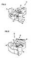
- FIG. 1A cable management panel or module is depicted in FIG. 1 generally at 30 .
- the panel 30includes a plurality of drawer assemblies 32 .
- the panel 30includes two drawer assemblies 32 .
- Each of the drawer assemblies 32includes a chassis 34 and a drawer 36 slidably mounted within the chassis 34 .
- Each drawer 36may include cable management structure, for example, devices for storing the cables or connecting the cables to other cables or fiber optic devices, such as attenuators, couplers, switches, wave division multiplexers, splitters or splices.
- Drawers 36are slidable relative to chassis 34 by way of two drawer slides 38 on opposite sides of the chassis 34 .
- Each drawer 36includes two latches 40 to secure the drawer 36 in a closed position (the position shown in FIG. 1 ).
- Each drawer 36includes a base 42 , a front wall 44 and a rear wall 46 . Note that the drawer 36 is absent of side walls, or is “side wall-free.” This structure allows for cable entry and exit and prevents cable damage during sliding movement of the drawers 36 when accessing the cables and connectors or other devices in the drawer 36 .
- the base 42 , front wall 44 and rear wall 46together define a storage interior 48 for holding and storing the cables.
- Each storage interior 48is sized for receiving cable management and/or distribution structures.
- the cables and management or distribution structures in the storage interior 48are protected.
- the distribution structurescan be conveniently mounted on a tray insert that drops into the storage interior 48 . This allows for convenient structuring of the drawer 36 to serve one or more desired functions in the panel 30 . Examples of tray inserts are described in co-pending and commonly assigned U.S. patent application Ser. No. 09/649,398, which is a continuation-in-part of application Ser. No. 09/490,379 (also co-pending and commonly assigned), each of which is incorporated by reference herein.
- each of the drawers 36is constructed to be stackable and linkable to form sub-cable management panels 31 .
- Such modularityalso allows for ease of use for a variety of different needs for the cable management system.
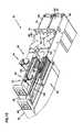
- a bracket 50is used to link each of the drawer assemblies 32 together.
- a perspective view of one preferred embodiment of the bracket 50is illustrated in FIG. 12
- mounting bracketswere attached to the side chassis with each drawer with several screws, for example, #4-40 UNC screws. It was found that if drawers connected together in this manner were dropped, the bracket would become loose from the drawers, leading to wobble between drawers in a multiple drawer assembly. Further, when the drawers would be opened, there sometimes would be rubbing and scraping if the drawers were loose from the bracket.
- the bracket 50as described herein, addresses these problems.
- the mounting bracket 50connects together each of the drawer assemblies 32 through an interlock arrangement 52 .
- the interlock arrangement 52includes at least one, and preferably a plurality, of non-threaded stud members 54 located in one of the mounting bracket 50 and the chassis 34 .
- the interlock arrangement 52includes at least one, and preferably a plurality, of apertures or holes 56 sized for receiving the non-threaded stud members 54 .
- the plurality of holes 56are defined by the other of the mounting bracket 50 and the chassis 34 .
- the interlock arrangement 52includes two non-threaded stud members 54 projecting from the chassis 34 (see FIGS. 13 - 14 ).
- the stud members 54may be formed from the chassis 34 itself (by punching or forming), or may be independent members permanently secured to the chassis 34 .
- the interlock arrangement 54includes at least 4 holes being defined by the mounting bracket 50 , receiving each of the non-threaded stud members 54 of each of the chassis 34 . These holes 56 are visible in FIGS. 10 and 12 .
- the bracket 50includes first and second mounting plates 60 , 61 arranged generally orthogonal to each other.
- the first mounting plate 60is utilized for securing each of the chassis 34 together.
- the second mounting plate 61is used to mount each of the drawer assemblies 32 together along other framework, typically together with other cable management panels 30 .
- Each of the holes 56is defined by and extends completely through the first mounting plate 60 .
- the first mounting plate 60also includes several more holes 62 for accommodating screws 64 , as used in prior arrangements, to help secure each of the drawer assemblies 32 together to the bracket 50 .
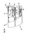
- each chassis 34is illustrated in FIGS. 13 and 14 . It can be seen that each chassis generally is an L-shaped frame piece 66 and, in addition to the non-threaded studs 54 projecting from the frame piece 66 , defines a plurality of holes 68 for accommodating the screws 64 .
- FIG. 11is a cross-sectional view illustrating the bracket 50 secured to one of the chassis 34 .
- Two of the studs 54can be seen in cross-section extending through two of the holes 56 .
- This interlock arrangement 52provides the cable management panel 30 with more strength and rigidity than prior arrangements that utilized screws. The interlock arrangement 52 helps to absorb the impact and thrust loading created by a drop scenario, by vibration, or by an earthquake.
- interlock arrangement 52may include a tab/slot arrangement, where a tab projects into and is bent over a slot.
- each of the drawer assemblies 32includes a take-up mechanism 70 to manage optical fibers entering and exiting the cable management panel 30 .
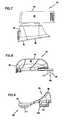
- each take-up mechanism 70includes a push member or radius limiter 72 .
- the radius limiter 72includes a frame piece 74 .
- the frame piece 74includes a vertically oriented curved wall 76 and a trough section 78 adjacent to the vertically curved wall 76 .
- the trough section 78is defined by a second vertically oriented wall 80 and a base 82 that bridges the vertically oriented wall 80 and the curved wall 76 (see FIG. 3 ).
- the curved wall 76is concavely shaped relative to the trough section 78 .
- the trough section 78also has a curved shape.
- the curved shape of the trough section 78is on a radius of about 1.25-2 in.
- the preferred radius limiter 72 shownincludes a cover member 84 .
- the cover member 84is oriented at least partially over the trough section 78 .
- the cover member 84 and the frame piece 74define a cable entry aperture 86 that is in communication with the trough section 78 to permit cables to enter through the aperture 86 and rest within the trough section 78 .
- the cable entry aperture 86defines a closed perimeter 88 .
- closed perimeterit is meant that the border that forms the aperture 86 is at least 90%, preferably 100%, closed to form a continuous, uninterrupted boundary.
- at least 75%, preferably at least 95%, and in most preferred embodiments, 100% of the perimeter 88 of the cable entry aperture 86is circumscribed by a flared cable guide surface 90 .
- the flared cable guide surface 90preferably takes the form of a smooth, contour 92 , such that the cable entry aperture 86 has the appearance of a trumpet flare or a bell-mouth 94 .
- the smooth contour 92preferably is bent on a radius of about 0.25-0.75 in.
- the flared cable guide surface 90helps to protect cables entering the cable entry aperture 86 and prevents such cables from bending too sharply and possibly losing some light transmission.
- the preferred embodimenthas the entire perimeter 88 of the cable entry aperture 86 to include the flared cable guide surface 90 .
- the cable entry aperture 86protects cables entering from any direction, including from a direction vertically above the radius limiter 72 .
- the cover member 84includes a finger 96 .
- the finger 96includes an extension 97 that defines a first free edge 98 and a second free edge 99 .
- a stem 102extends between the extension 97 and an attachment portion 104 .
- the first free edge 98defines a portion of the flared guide surface 90 .
- the second free edge 99selectively engages the vertically oriented wall 76 of the frame piece 74 through a latch arrangement 106 (FIGS. 2 and 4 ).
- the latch arrangement 106includes a hook and projection arrangement 108 , where a hook from one of the finger 96 and frame piece 74 engages a projection from the other of the finger 96 and frame piece 74 .
- the latch arrangement 106includes the finger 96 having a hook 110 defining an aperture 111 , through which a projection 112 extending or projecting from the vertically oriented curved wall 76 of the frame piece 74 is defined.
- the latch arrangement 106permits the finger 96 to be releasably secured to the frame piece 74 .
- this latch arrangement 106permits the finger 96 to be selectively moved from, and pivoted at the attachment portion 104 , from the frame piece 74 to permit the installation of cables through the cable entry aperture 86 and into the trough section 78 .
- the attachment portion 104helps to pivotally secure the finger 96 to the frame piece 74 .
- the attachment portion 104includes a pair of extruding tabs 114 , 116 , projecting from the extension 97 .
- the tabs 114 , 116are snapped around a member 75 within the frame piece 74 of the radius limiter 72 in a manner which allows the frame piece 74 to securely hold the finger 96 and permit the finger 96 to be selectively pivoted away from and then back toward the trough section 78 (see FIG. 6 ), along a hinge point 118 .
- the latch arrangement 106provides for a secure interlock between the finger 96 and the frame piece 74 to prevent unintended bending away of the finger 96 from the frame piece 74 if fibers or cables tend to pull it up during manipulation of the drawer assembly 32 .
- the hinge point 118permits selective lifting of the cover member 84 away from remaining portions of the radius limiter 72 to facilitate fiber loading.
- the cover member 84may also include a second finger 100 (FIGS. 11 and 18 ).
- Finger 100in the one shown, is oriented generally at a right angle to the finger 96 and is pivotally mounted relative to the frame 74 . Finger 100 also helps to hold the cables in place within the radius limiter 72 .
- the latch arrangement 106is released to allow the finger 96 to be moved relative to the frame 74 .
- the finger 96is pivoted about the hinge point 118 that defines a gap or space through which the cable may enter. If present, the second finger 100 is also pivoted away from the frame 74 .
- the cableis then oriented and rested within the trough section 78 .
- the finger 96is again oriented against the frame piece 74 to close the gap or space, and the latch arrangement 106 is secured by having the projection 112 extend into the aperture 111 of the hook 110 . If present, the second finger 100 is returned against the frame 74 .
- the cableis resting against the flared cable guide surface 90 defined by the first free edge 98 of the finger 96 .
- the flared cable guide surface 90helps to prevent the cable from bending too sharply.
- the shape of the trough section 78also controls the radius of the cable and prevents it from bending too sharply.
- the radius limiter 72is preferably slidably mounted relative to the drawer assembly 32 . Movement of the radius limiter 72 is controlled with synchronized movement with the drawer 36 to ensure that the cables do not bend too sharply when the drawer 36 is being opened or closed relative to the chassis 34 . If the cables were bent too sharply, this may cause loss of signal strength or loss of transmission.
- the cable management panel 30includes a control mechanism 125 ( FIGS. 15-19 ) that is secured to the drawer assembly 32 to synchronize slidable movement of the cable radius limiter 72 relative to slidable movement of the drawer 36 within the chassis 34 .
- the control mechanism 125includes a rotating member 126 , such as a roller or wheel 128 .
- Preferred wheels 128will include a compressible ring 129 ( FIG. 17 ) that circumscribes the wheel 128 to help provide for a smooth interface and introduce some friction for smooth operation.
- the wheel 128is oriented to rotate between the drawer 36 and the chassis 34 .
- the wheel 128has an axis of rotation 130 that is transverse to a direction of slidable movement of the cable radius limiter 72 .
- FIG. 16the direction of slidable movement of the cable radius limiter 72 is shown at arrow 132 .
- this direction 132is a horizontal direction. It is also the direction that corresponds to the slidable motion of the drawer 36 relative to the chassis 34 .
- the axis of rotation 130extends, in the particular orientation shown in FIG.
- the axis of rotation 130is normal (i.e., perpendicular) to the radius limiter 72 .
- the control mechanism 125includes a bracket 134 having an axle 136 .
- the wheel 128is mounted for rotation on the axle 136 .
- the axle 136is co-linear with and defines the axis of rotation 130 .
- the preferred bracket 134 shownincludes a projection arrangement 138 that allows the bracket 134 to be secured to the cable radius limiter 72 .
- the projection arrangement 138includes a first projection 140 and a second projection 142 .
- Each of the first projection 140 and second projection 142includes a tab 144 , 145 that extends or projects into and locks with a suitable receiving aperture 146 , 147 ( FIG. 17 ) in the frame piece 74 of the radius limiter 72 .
- the bracket 134can be secured to the radius limiter 72 , and through an elongated slot 150 defined by the base 42 of the drawer 36 .
- the slot 150allows for assembly of the radius limiter 72 to the drawer 36 .
- the bracket 134also includes a catch 152 projecting from a side and in a direction opposite to the direction that the projection arrangement 138 projects.
- the catch 152defines one end 154 of the bracket 134 .
- the first projection 140forms an opposite end 156 of the bracket 134 .
- the catch 152is selectively engaged with a stop member 158 on the chassis 34 .
- the catch 152 of the bracket 134selectively engages the stop member 158 when the drawer 36 and the radius limiter 72 are slid relative to the chassis 34 . This engagement prevents the drawer 36 from being totally separated from the chassis 34 when sliding the drawer 36 from the chassis 34 .
- the chassis 34was described above as being an L-shaped frame piece 66 .
- the L-shaped frame piece 66includes a base 160 that is located in a plane generally parallel to the base 42 of the drawer, when the drawer assembly 32 is in operable assembly, and a side wall 162 extending normal to the chassis base 160 . This side wall 162 provides one of the surfaces against which the wheel 128 rotates.
- the wheel guide 164is a generally elongated structural member defining a smooth guide surface 165 . As can be seen in FIGS. 15 and 17 , the wheel guide 164 is adjacent to and generally parallel to the elongated slot 150 in the drawer 36 .
- the wheel 128rotates about its axle 136 between and against the guide surface 165 of the wheel guide 164 and the chassis side wall 162 .
- the location of the wheel 128 secured to the radius limiter 72 and between the drawer 36 and chassis 34allows the radius limiter 72 to move at one-half of the speed of the movement of the drawer 36 relative to the chassis 34 .
- each of the drawer assemblies 32preferably includes drawer slide 38 .
- the drawer slide 38is the type of slide that is described in U.S. Pat. No. 5,209,572, which is incorporated by reference herein.
- the drawer slide 38includes symmetrically identical outside channel members 167 , 168 for securing to the drawer 36 and chassis 34 , respectively.
- An inner retainer 169slidably retains ball bearings (not shown) that are trapped between the channel members 168 , 169 .
- the channel member 167slides relative to the channel member 168 with the ball bearings rotating between the retainer 169 and the channel members 167 , 168 to help create smooth, slidable motion.
- the wheel 128When the drawer 36 is slid relative to the chassis 34 , the wheel 128 is rotated between the drawer 36 and chassis 34 (in particular, between the wheel guide 164 and the side wall 162 of the chassis 34 ), and the wheel 128 is rotated about the axis of rotation 130 that is transverse to the direction of slidable movement of the cable radius limiter 72 , and that is oriented normally to the radius limiter 72 .
Landscapes
- Physics & Mathematics (AREA)
- General Physics & Mathematics (AREA)
- Optics & Photonics (AREA)
- Drawers Of Furniture (AREA)
- Light Guides In General And Applications Therefor (AREA)
- Insertion, Bundling And Securing Of Wires For Electric Apparatuses (AREA)
Abstract
Description
Claims (27)
Priority Applications (14)
| Application Number | Priority Date | Filing Date | Title |
|---|---|---|---|
| US09/900,465US7079744B2 (en) | 2001-07-06 | 2001-07-06 | Cable management panel with sliding drawer and methods |
| PCT/US2002/019981WO2003005095A2 (en) | 2001-07-06 | 2002-06-20 | Cable management panel with sliding drawer and methods |
| US11/349,687US7231125B2 (en) | 2001-07-06 | 2006-02-08 | Cable management panel with sliding drawer and methods |
| US11/799,010US7373071B2 (en) | 2001-07-06 | 2007-04-30 | Cable management panel with sliding drawer and methods |
| US12/148,142US7480438B2 (en) | 2001-07-06 | 2008-04-15 | Cable management panel with sliding drawer and methods |
| US12/316,799US7664362B2 (en) | 2001-07-06 | 2008-12-15 | Cable management panel with sliding drawer and methods |
| US12/655,363US8078029B2 (en) | 2001-07-06 | 2009-12-28 | Cable management panel with sliding drawer and methods |
| US13/306,186US20120076466A1 (en) | 2001-07-06 | 2011-11-29 | Cable management panel with sliding drawer and methods |
| US14/699,877US9442267B2 (en) | 2001-07-06 | 2015-04-29 | Cable management panel with sliding drawer and methods |
| US15/262,445US20170131507A1 (en) | 2001-07-06 | 2016-09-12 | Cable management panel with sliding drawer and methods |
| US15/813,454US10146023B2 (en) | 2001-07-06 | 2017-11-15 | Cable management panel with sliding drawer and methods |
| US16/204,695US20190361189A1 (en) | 2001-07-06 | 2018-11-29 | Cable management panel with sliding drawer and methods |
| US16/782,247US10989889B2 (en) | 2001-07-06 | 2020-02-05 | Cable management panel with sliding drawer and methods |
| US17/238,890US11320619B2 (en) | 2001-07-06 | 2021-04-23 | Cable management panel with sliding drawer and methods |
Applications Claiming Priority (1)
| Application Number | Priority Date | Filing Date | Title |
|---|---|---|---|
| US09/900,465US7079744B2 (en) | 2001-07-06 | 2001-07-06 | Cable management panel with sliding drawer and methods |
Related Child Applications (1)
| Application Number | Title | Priority Date | Filing Date |
|---|---|---|---|
| US11/349,687ContinuationUS7231125B2 (en) | 2001-07-06 | 2006-02-08 | Cable management panel with sliding drawer and methods |
Publications (2)
| Publication Number | Publication Date |
|---|---|
| US20030007767A1 US20030007767A1 (en) | 2003-01-09 |
| US7079744B2true US7079744B2 (en) | 2006-07-18 |
Family
ID=25412575
Family Applications (13)
| Application Number | Title | Priority Date | Filing Date |
|---|---|---|---|
| US09/900,465Expired - LifetimeUS7079744B2 (en) | 2001-07-06 | 2001-07-06 | Cable management panel with sliding drawer and methods |
| US11/349,687Expired - LifetimeUS7231125B2 (en) | 2001-07-06 | 2006-02-08 | Cable management panel with sliding drawer and methods |
| US11/799,010Expired - Fee RelatedUS7373071B2 (en) | 2001-07-06 | 2007-04-30 | Cable management panel with sliding drawer and methods |
| US12/148,142Expired - LifetimeUS7480438B2 (en) | 2001-07-06 | 2008-04-15 | Cable management panel with sliding drawer and methods |
| US12/316,799Expired - Fee RelatedUS7664362B2 (en) | 2001-07-06 | 2008-12-15 | Cable management panel with sliding drawer and methods |
| US12/655,363Expired - Fee RelatedUS8078029B2 (en) | 2001-07-06 | 2009-12-28 | Cable management panel with sliding drawer and methods |
| US13/306,186AbandonedUS20120076466A1 (en) | 2001-07-06 | 2011-11-29 | Cable management panel with sliding drawer and methods |
| US14/699,877Expired - Fee RelatedUS9442267B2 (en) | 2001-07-06 | 2015-04-29 | Cable management panel with sliding drawer and methods |
| US15/262,445AbandonedUS20170131507A1 (en) | 2001-07-06 | 2016-09-12 | Cable management panel with sliding drawer and methods |
| US15/813,454Expired - Fee RelatedUS10146023B2 (en) | 2001-07-06 | 2017-11-15 | Cable management panel with sliding drawer and methods |
| US16/204,695AbandonedUS20190361189A1 (en) | 2001-07-06 | 2018-11-29 | Cable management panel with sliding drawer and methods |
| US16/782,247Expired - Fee RelatedUS10989889B2 (en) | 2001-07-06 | 2020-02-05 | Cable management panel with sliding drawer and methods |
| US17/238,890Expired - LifetimeUS11320619B2 (en) | 2001-07-06 | 2021-04-23 | Cable management panel with sliding drawer and methods |
Family Applications After (12)
| Application Number | Title | Priority Date | Filing Date |
|---|---|---|---|
| US11/349,687Expired - LifetimeUS7231125B2 (en) | 2001-07-06 | 2006-02-08 | Cable management panel with sliding drawer and methods |
| US11/799,010Expired - Fee RelatedUS7373071B2 (en) | 2001-07-06 | 2007-04-30 | Cable management panel with sliding drawer and methods |
| US12/148,142Expired - LifetimeUS7480438B2 (en) | 2001-07-06 | 2008-04-15 | Cable management panel with sliding drawer and methods |
| US12/316,799Expired - Fee RelatedUS7664362B2 (en) | 2001-07-06 | 2008-12-15 | Cable management panel with sliding drawer and methods |
| US12/655,363Expired - Fee RelatedUS8078029B2 (en) | 2001-07-06 | 2009-12-28 | Cable management panel with sliding drawer and methods |
| US13/306,186AbandonedUS20120076466A1 (en) | 2001-07-06 | 2011-11-29 | Cable management panel with sliding drawer and methods |
| US14/699,877Expired - Fee RelatedUS9442267B2 (en) | 2001-07-06 | 2015-04-29 | Cable management panel with sliding drawer and methods |
| US15/262,445AbandonedUS20170131507A1 (en) | 2001-07-06 | 2016-09-12 | Cable management panel with sliding drawer and methods |
| US15/813,454Expired - Fee RelatedUS10146023B2 (en) | 2001-07-06 | 2017-11-15 | Cable management panel with sliding drawer and methods |
| US16/204,695AbandonedUS20190361189A1 (en) | 2001-07-06 | 2018-11-29 | Cable management panel with sliding drawer and methods |
| US16/782,247Expired - Fee RelatedUS10989889B2 (en) | 2001-07-06 | 2020-02-05 | Cable management panel with sliding drawer and methods |
| US17/238,890Expired - LifetimeUS11320619B2 (en) | 2001-07-06 | 2021-04-23 | Cable management panel with sliding drawer and methods |
Country Status (2)
| Country | Link |
|---|---|
| US (13) | US7079744B2 (en) |
| WO (1) | WO2003005095A2 (en) |
Cited By (101)
| Publication number | Priority date | Publication date | Assignee | Title |
|---|---|---|---|---|
| US20070047896A1 (en)* | 2005-08-31 | 2007-03-01 | Scott Kowalczyk | Cabinet including optical bulkhead plate for blown fiber system |
| US20070201806A1 (en)* | 2001-07-06 | 2007-08-30 | Adc Telecommunications, Inc. | Cable management panel with sliding drawer and methods |
| US20080085093A1 (en)* | 2006-10-10 | 2008-04-10 | Dennis Krampotich | Cable management drawer with access panel |
| US7418182B2 (en) | 2006-10-10 | 2008-08-26 | Adc Telecommunications, Inc. | Cable management drawer with access panel |
| US20080219632A1 (en)* | 2007-03-09 | 2008-09-11 | Smith Trevor D | Telecommunication rack unit tray |
| US20080239693A1 (en)* | 2007-03-27 | 2008-10-02 | Mark Hendrix | Compact fiber panel with sliding tray having removable hood |
| US20080304803A1 (en)* | 2007-06-06 | 2008-12-11 | Adc Telecommunications, Inc. | Rear drawer latch |
| US20090245745A1 (en)* | 2008-03-28 | 2009-10-01 | Dennis Krampotich | Rear latch arrangement for sliding drawer |
| US20090245746A1 (en)* | 2008-03-28 | 2009-10-01 | Dennis Krampotich | Universal cable management panel |
| US20090261211A1 (en)* | 2008-04-21 | 2009-10-22 | International Business Machines Corporation | Cable Management System |
| US20090274430A1 (en)* | 2008-05-05 | 2009-11-05 | Dennis Krampotich | Drawer arrangement with rack and pinion |
| US20090274429A1 (en)* | 2008-05-05 | 2009-11-05 | Dennis Krampotich | Front-access locking arrangement for sliding drawer |
| US20090310929A1 (en)* | 2007-10-10 | 2009-12-17 | Adc Telecommunications, Inc. | Optical fiber interconnection apparatus |
| US20100012599A1 (en)* | 2002-10-21 | 2010-01-21 | Adc Telecommunications, Inc. | High density panel with rotating tray |
| US20100054683A1 (en)* | 2008-08-29 | 2010-03-04 | Cooke Terry L | Rear-Installable Fiber Optic Modules and Equipment |
| US20100054682A1 (en)* | 2008-08-29 | 2010-03-04 | Cooke Terry L | Independently Translatable Modules and Fiber Optic Equipment Trays in Fiber Optic Equipment |
| US20100195969A1 (en)* | 2009-02-02 | 2010-08-05 | Bryan Kennedy | Multi-fiber cable management panel |
| US20100272410A1 (en)* | 2009-04-24 | 2010-10-28 | Dennis Krampotich | Radius limiter cable retention bracket, clamp and panel |
| US20100296790A1 (en)* | 2009-05-21 | 2010-11-25 | Cooke Terry L | Fiber Optic Equipment Supporting Moveable Fiber Optic Equipment Tray(s) and Module(s), and Related Equipment and Methods |
| US20100310225A1 (en)* | 2009-06-08 | 2010-12-09 | Anderson Timothy W | High density patching system for cable and optical fiber |
| US7856166B2 (en) | 2008-09-02 | 2010-12-21 | Corning Cable Systems Llc | High-density patch-panel assemblies for optical fiber telecommunications |
| US20110211801A1 (en)* | 2010-03-01 | 2011-09-01 | Mcgranahan Daniel S | Cable Routing Guide With Cable Retainer |
| US8433171B2 (en) | 2009-06-19 | 2013-04-30 | Corning Cable Systems Llc | High fiber optic cable packing density apparatus |
| US8457464B2 (en) | 2011-09-26 | 2013-06-04 | Hubbell Incorporated | Cable enclosure and radius-limiting cable guide with integral magnetic door catch |
| US8542973B2 (en) | 2010-04-23 | 2013-09-24 | Ccs Technology, Inc. | Fiber optic distribution device |
| US8556356B2 (en) | 2011-02-21 | 2013-10-15 | Commscope, Inc. Of North Carolina | Communication shelf having supports for pivotable adapter panels and method of mounting adapter panels therein |
| US8593828B2 (en) | 2010-02-04 | 2013-11-26 | Corning Cable Systems Llc | Communications equipment housings, assemblies, and related alignment features and methods |
| US8625950B2 (en) | 2009-12-18 | 2014-01-07 | Corning Cable Systems Llc | Rotary locking apparatus for fiber optic equipment trays and related methods |
| US8660397B2 (en) | 2010-04-30 | 2014-02-25 | Corning Cable Systems Llc | Multi-layer module |
| US8662760B2 (en) | 2010-10-29 | 2014-03-04 | Corning Cable Systems Llc | Fiber optic connector employing optical fiber guide member |
| US8699838B2 (en) | 2009-05-14 | 2014-04-15 | Ccs Technology, Inc. | Fiber optic furcation module |
| US8705926B2 (en) | 2010-04-30 | 2014-04-22 | Corning Optical Communications LLC | Fiber optic housings having a removable top, and related components and methods |
| US8712206B2 (en) | 2009-06-19 | 2014-04-29 | Corning Cable Systems Llc | High-density fiber optic modules and module housings and related equipment |
| US8718436B2 (en) | 2010-08-30 | 2014-05-06 | Corning Cable Systems Llc | Methods, apparatuses for providing secure fiber optic connections |
| WO2014133943A1 (en)* | 2013-02-27 | 2014-09-04 | Adc Telecommunications, Inc. | Slidable fiber optic connection module with cable slack management |
| US8879881B2 (en) | 2010-04-30 | 2014-11-04 | Corning Cable Systems Llc | Rotatable routing guide and assembly |
| US8913866B2 (en) | 2010-03-26 | 2014-12-16 | Corning Cable Systems Llc | Movable adapter panel |
| US8953924B2 (en) | 2011-09-02 | 2015-02-10 | Corning Cable Systems Llc | Removable strain relief brackets for securing fiber optic cables and/or optical fibers to fiber optic equipment, and related assemblies and methods |
| US8958679B2 (en) | 2010-03-02 | 2015-02-17 | Tyco Electronics Services Gmbh | Fibre-optic telecommunications module |
| US8989547B2 (en) | 2011-06-30 | 2015-03-24 | Corning Cable Systems Llc | Fiber optic equipment assemblies employing non-U-width-sized housings and related methods |
| US8985862B2 (en) | 2013-02-28 | 2015-03-24 | Corning Cable Systems Llc | High-density multi-fiber adapter housings |
| US8995812B2 (en) | 2012-10-26 | 2015-03-31 | Ccs Technology, Inc. | Fiber optic management unit and fiber optic distribution device |
| US9002166B2 (en) | 2011-10-07 | 2015-04-07 | Adc Telecommunications, Inc. | Slidable fiber optic connection module with cable slack management |
| US9008485B2 (en) | 2011-05-09 | 2015-04-14 | Corning Cable Systems Llc | Attachment mechanisms employed to attach a rear housing section to a fiber optic housing, and related assemblies and methods |
| US9020320B2 (en) | 2008-08-29 | 2015-04-28 | Corning Cable Systems Llc | High density and bandwidth fiber optic apparatuses and related equipment and methods |
| US9022814B2 (en) | 2010-04-16 | 2015-05-05 | Ccs Technology, Inc. | Sealing and strain relief device for data cables |
| US9042702B2 (en) | 2012-09-18 | 2015-05-26 | Corning Cable Systems Llc | Platforms and systems for fiber optic cable attachment |
| US9038832B2 (en) | 2011-11-30 | 2015-05-26 | Corning Cable Systems Llc | Adapter panel support assembly |
| US9057859B2 (en) | 2011-10-07 | 2015-06-16 | Adc Telecommunications, Inc. | Slidable fiber optic connection module with cable slack management |
| US9059578B2 (en) | 2009-02-24 | 2015-06-16 | Ccs Technology, Inc. | Holding device for a cable or an assembly for use with a cable |
| US9075216B2 (en) | 2009-05-21 | 2015-07-07 | Corning Cable Systems Llc | Fiber optic housings configured to accommodate fiber optic modules/cassettes and fiber optic panels, and related components and methods |
| US9075203B2 (en) | 2012-01-17 | 2015-07-07 | Adc Telecommunications, Inc. | Fiber optic adapter block |
| US9075217B2 (en) | 2010-04-30 | 2015-07-07 | Corning Cable Systems Llc | Apparatuses and related components and methods for expanding capacity of fiber optic housings |
| US9116324B2 (en) | 2010-10-29 | 2015-08-25 | Corning Cable Systems Llc | Stacked fiber optic modules and fiber optic equipment configured to support stacked fiber optic modules |
| US9128262B2 (en) | 2013-02-05 | 2015-09-08 | Adc Telecommunications, Inc. | Slidable telecommunications tray with cable slack management |
| US9170391B2 (en) | 2011-10-07 | 2015-10-27 | Adc Telecommunications, Inc. | Slidable fiber optic connection module with cable slack management |
| CN105074525A (en)* | 2013-01-29 | 2015-11-18 | 泰科电子瑞侃有限公司 | Fiber Distribution System |
| US9195021B2 (en) | 2012-09-21 | 2015-11-24 | Adc Telecommunications, Inc. | Slidable fiber optic connection module with cable slack management |
| US9213161B2 (en) | 2010-11-05 | 2015-12-15 | Corning Cable Systems Llc | Fiber body holder and strain relief device |
| US9250409B2 (en) | 2012-07-02 | 2016-02-02 | Corning Cable Systems Llc | Fiber-optic-module trays and drawers for fiber-optic equipment |
| US9279951B2 (en) | 2010-10-27 | 2016-03-08 | Corning Cable Systems Llc | Fiber optic module for limited space applications having a partially sealed module sub-assembly |
| CN105393152A (en)* | 2013-05-20 | 2016-03-09 | Adc电信股份有限公司 | Cable routing system exit structure |
| US9360648B2 (en) | 2011-09-16 | 2016-06-07 | Commscope Technologies Llc | Systems and methods for the management of fiber optic cables |
| US9435975B2 (en) | 2013-03-15 | 2016-09-06 | Commscope Technologies Llc | Modular high density telecommunications frame and chassis system |
| US9500829B2 (en) | 2011-09-16 | 2016-11-22 | Commscope Technologies Llc | Systems and methods for the management of fiber optic cables |
| US9519118B2 (en) | 2010-04-30 | 2016-12-13 | Corning Optical Communications LLC | Removable fiber management sections for fiber optic housings, and related components and methods |
| US9541726B2 (en) | 2013-04-24 | 2017-01-10 | Adc Czech Republic, S.R.O. | Optical fiber distribution system |
| US9632270B2 (en) | 2010-04-30 | 2017-04-25 | Corning Optical Communications LLC | Fiber optic housings configured for tool-less assembly, and related components and methods |
| US9645317B2 (en) | 2011-02-02 | 2017-05-09 | Corning Optical Communications LLC | Optical backplane extension modules, and related assemblies suitable for establishing optical connections to information processing modules disposed in equipment racks |
| US9720195B2 (en) | 2010-04-30 | 2017-08-01 | Corning Optical Communications LLC | Apparatuses and related components and methods for attachment and release of fiber optic housings to and from an equipment rack |
| US9817201B2 (en) | 2016-04-12 | 2017-11-14 | Ciena Corporation | Sliding assembly and method for fiber management |
| US9958631B2 (en) | 2013-06-28 | 2018-05-01 | CommScope Connectivity Belgium BVBA | Optical fiber distribution system with staggered cable guides |
| US10025055B2 (en) | 2014-09-16 | 2018-07-17 | CommScope Connectivity Belgium BVBA | Multi-positionable telecommunications tray |
| US10082636B2 (en) | 2012-09-21 | 2018-09-25 | Commscope Technologies Llc | Slidable fiber optic connection module with cable slack management |
| US10175440B2 (en) | 2013-03-19 | 2019-01-08 | Adc Czech Republic, S.R.O. | Moveable bend control and patch cord support for telecommunications panel |
| US10209470B2 (en) | 2014-09-16 | 2019-02-19 | CommScope Connectivity Belgium BVBA | Telecommunications tray with a cable routing path extending through a pivot hinge |
| US10247886B2 (en) | 2014-12-10 | 2019-04-02 | Commscope Technologies Llc | Fiber optic cable slack management module |
| US10254496B2 (en) | 2015-04-23 | 2019-04-09 | CommScope Connectivity Belgium BVBA | Telecommunications panel assembly with movable adapters |
| US10261281B2 (en) | 2015-04-03 | 2019-04-16 | CommScope Connectivity Belgium BVBA | Telecommunications distribution elements |
| US10409020B2 (en) | 2013-04-24 | 2019-09-10 | CommScope Connectivity Belgium BVBA | Universal mounting mechanism for mounting a telecommunications chassis to a telecommunciations fixture |
| US10502917B2 (en) | 2014-09-16 | 2019-12-10 | CommScope Connectivity Belgium BVBA | Telecommunications tray assembly |
| US10539757B2 (en) | 2016-04-19 | 2020-01-21 | Commscope, Inc. Of North Carolina | Telecommunications chassis with slidable trays |
| US10606007B2 (en) | 2015-12-16 | 2020-03-31 | CommScope Connectivity Belgium BVBA | Telecommunications distribution elements |
| US11109506B2 (en) | 2019-11-14 | 2021-08-31 | Ciena Corporation | Fiber management sliding tray system |
| US11175469B2 (en) | 2017-10-26 | 2021-11-16 | CommScope Connectivity Belgium BVBA | Telecommunications system |
| US11215767B2 (en) | 2017-06-07 | 2022-01-04 | Commscope Technologies Llc | Fiber optic adapter and cassette |
| US11256054B2 (en) | 2018-04-16 | 2022-02-22 | Commscope Technologies Llc | Adapter structure |
| US11294135B2 (en) | 2008-08-29 | 2022-04-05 | Corning Optical Communications LLC | High density and bandwidth fiber optic apparatuses and related equipment and methods |
| US11385429B2 (en) | 2017-10-18 | 2022-07-12 | Commscope Technologies Llc | Fiber optic connection cassette |
| US11409067B2 (en) | 2018-08-31 | 2022-08-09 | CommScope Connectivity Belgium BVBA | Frame assemblies for optical fiber distribution elements |
| US11448844B2 (en) | 2018-08-31 | 2022-09-20 | CommScope Connectivity Belgium BVBA | Frame assemblies for optical fiber distribution elements |
| US11448831B2 (en) | 2018-08-31 | 2022-09-20 | CommScope Connectivity Belgium BVBA | Frame assemblies for optical fiber distribution elements |
| US11448845B2 (en) | 2018-08-31 | 2022-09-20 | CommScope Connectivity Belgium BVBA | Frame assemblies for optical fiber distribution elements |
| US11635578B2 (en) | 2018-04-17 | 2023-04-25 | CommScope Connectivity Belgium BVBA | Telecommunications distribution elements |
| US11674345B2 (en) | 2016-04-19 | 2023-06-13 | Commscope, Inc. Of North Carolina | Door assembly for a telecommunications chassis with a combination hinge structure |
| US11852882B2 (en) | 2018-02-28 | 2023-12-26 | Commscope Technologies Llc | Packaging assembly for telecommunications equipment |
| US11947177B2 (en) | 2019-01-25 | 2024-04-02 | CommScope Connectivity Belgium BVBA | Frame assemblies for optical fiber distribution elements |
| US12007615B2 (en) | 2018-10-23 | 2024-06-11 | CommScope Connectivity Belgium BVBA | Frame assemblies for optical fiber distribution elements |
| US12050358B2 (en) | 2018-08-31 | 2024-07-30 | CommScope Connectivity Belgium BVBA | Frame assemblies for optical fiber distribution elements |
| US12099246B2 (en) | 2020-01-24 | 2024-09-24 | CommScope Connectivity Belgium BVBA | Telecommunications distribution elements |
| US12174443B2 (en) | 2020-01-22 | 2024-12-24 | CommScope Connectivity Belgium BVBA | Cable termination units for optical fiber distribution elements |
Families Citing this family (45)
| Publication number | Priority date | Publication date | Assignee | Title |
|---|---|---|---|---|
| US6804447B2 (en) | 2002-11-05 | 2004-10-12 | Adc Telecommunications, Inc. | Fiber panel with integrated couplers |
| US7171099B2 (en) | 2003-07-31 | 2007-01-30 | Adc Telecommunications, Inc. | Slide arrangement for cable drawer |
| US6944383B1 (en) | 2004-04-12 | 2005-09-13 | Adc Telecommunications, Inc. | Cable management panel with sliding drawer and methods |
| US7302149B2 (en)* | 2004-09-09 | 2007-11-27 | Adc Telecommunications, Inc. | WDM systems and methods |
| US7277273B2 (en)* | 2004-09-23 | 2007-10-02 | Special Product Company | Equipment cabinet providing full access to equipment housed therein |
| US7416349B2 (en)* | 2005-07-27 | 2008-08-26 | Adc Telecommunications, Inc. | Fiber optic adapter module |
| US7397996B2 (en)* | 2005-08-02 | 2008-07-08 | Adc Telecommunications, Inc. | Cable management panel with rear entry |
| US7627221B2 (en)* | 2006-06-23 | 2009-12-01 | Stephen James Morris | Mounting system for telecommunications panels |
| US7409137B2 (en)* | 2006-10-04 | 2008-08-05 | Adc Telecommunications, Inc. | Slide arrangement for cable drawer |
| FR2922500B1 (en)* | 2007-10-23 | 2009-12-04 | Peugeot Citroen Automobiles Sa | PROTECTIVE COVER FOR CONNECTING BEAM OF AN AUTORADIO. |
| ES2560802T3 (en) | 2008-08-27 | 2016-02-22 | Adc Telecommunications, Inc. | Fiber optic adapter with integrally molded bushing alignment structure |
| US8326107B2 (en)* | 2008-08-29 | 2012-12-04 | Corning Cable Systems Llc | Rear-slidable extension in a fiber optic equipment tray |
| WO2010059623A1 (en) | 2008-11-21 | 2010-05-27 | Adc Telecommunications, Inc. | Fiber optic telecommunications module |
| US20100220967A1 (en)* | 2009-02-27 | 2010-09-02 | Cooke Terry L | Hinged Fiber Optic Module Housing and Module |
| EP2433165B1 (en)* | 2009-05-21 | 2016-12-21 | Corning Optical Communications LLC | Fiber optic equipment with guides and rails configured with stopping positions |
| US8385710B2 (en)* | 2009-11-12 | 2013-02-26 | Panduit Corp. | Fiber tray |
| US8824851B2 (en) | 2010-08-27 | 2014-09-02 | Commscope, Inc. Of North Carolina | Communications enclosure having rear mounted bracket and method of securing a cable bundle to a communications enclosure using a rear mounted bracket |
| US9417418B2 (en) | 2011-09-12 | 2016-08-16 | Commscope Technologies Llc | Flexible lensed optical interconnect device for signal distribution |
| RU2611105C2 (en) | 2011-10-07 | 2017-02-21 | Адс Телекоммьюникейшнз, Инк. | Fibre-optic cartridge, system and method |
| US9146362B2 (en) | 2012-09-21 | 2015-09-29 | Adc Telecommunications, Inc. | Insertion and removal tool for a fiber optic ferrule alignment sleeve |
| NZ706687A (en) | 2012-09-28 | 2017-09-29 | Adc Telecommunications Inc | Fiber optic cassette |
| US9146374B2 (en) | 2012-09-28 | 2015-09-29 | Adc Telecommunications, Inc. | Rapid deployment packaging for optical fiber |
| US10915843B1 (en) | 2012-10-04 | 2021-02-09 | Groupon, Inc. | Method, apparatus, and computer program product for identification of supply sources |
| US12198156B2 (en) | 2012-10-04 | 2025-01-14 | Bytedance Inc. | Method, apparatus, and computer program product for calculating a supply based on travel propensity |
| US12387228B2 (en) | 2012-10-04 | 2025-08-12 | Bytedance Inc | Method, apparatus, and computer program product for forecasting demand using real time demand |
| US9223094B2 (en) | 2012-10-05 | 2015-12-29 | Tyco Electronics Nederland Bv | Flexible optical circuit, cassettes, and methods |
| US9348104B2 (en)* | 2012-12-11 | 2016-05-24 | CommScope Connectivity Belgium BVBA | Universal cable management system for telecommunications rack |
| US20150019287A1 (en) | 2013-03-14 | 2015-01-15 | Groupon, Inc. | Method, apparatus, and computer program product for providing mobile location based sales lead identification |
| US9285546B2 (en) | 2014-06-04 | 2016-03-15 | All Systems Broadband, Inc. | Conduit for passing a plurality of fiber optic cables through a fiber optic cassette shelf |
| US9632271B2 (en)* | 2014-06-17 | 2017-04-25 | Ortronics, Inc. | Modularly mountable cable management systems and associated methods |
| WO2016012550A2 (en)* | 2014-07-25 | 2016-01-28 | Tyco Electronics Raychem Bvba | Telecommunications distribution elements |
| CN204462469U (en)* | 2015-01-07 | 2015-07-08 | 泰科电子(上海)有限公司 | Optical cable fan-out device |
| MX2017014377A (en) | 2015-05-15 | 2018-08-15 | Adc Telecommunications Shanghai Distrib Co Ltd | Alignment sleeve assembly and optical fibre adapter. |
| US10670822B2 (en) | 2017-06-28 | 2020-06-02 | Afl Telecommunications Llc | High density patch panel with modular cassettes |
| US11409068B2 (en) | 2017-10-02 | 2022-08-09 | Commscope Technologies Llc | Fiber optic circuit and preparation method |
| EP4236343B1 (en) | 2019-04-17 | 2025-03-12 | Afl Ig Llc | Patch panel with lifting cassette removal |
| CN110391623A (en)* | 2019-06-10 | 2019-10-29 | 通号工程局集团有限公司 | Wall-mounted optical cable fixing device and manufacturing method thereof |
| CN112188786B (en)* | 2019-07-02 | 2022-01-14 | 川湖科技股份有限公司 | Wire management assembly |
| DE102019219182B4 (en)* | 2019-12-09 | 2025-08-28 | Abb Ag | CABLE FASTENING ACCESSORIES |
| US12339511B2 (en) | 2020-03-31 | 2025-06-24 | Commscope Technologies Llc | Fiber optic cable management systems and methods |
| US11169345B1 (en)* | 2020-05-11 | 2021-11-09 | Google Llc | Sliding tray for fiber optic panel assembly |
| US11947178B2 (en) | 2020-09-17 | 2024-04-02 | Panduit Corp. | Optical distribution and splice frame including cassettes |
| EP4315878A4 (en)* | 2021-03-26 | 2025-02-26 | CommScope Technologies LLC | COMMUNICATION PANEL SYSTEMS AND ASSOCIATED TRAYS |
| CN113517650B (en)* | 2021-04-23 | 2023-03-03 | 山东聚辰电缆有限公司 | Auxiliary cable trough repairing device for rail transit |
| US20240151924A1 (en)* | 2022-11-04 | 2024-05-09 | Ppc Broadband, Inc. | Modular, conformable, optical fiber management cassette that is structurally configured to receive connectorized optical cables |
Citations (40)
| Publication number | Priority date | Publication date | Assignee | Title |
|---|---|---|---|---|
| US4373776A (en) | 1980-06-30 | 1983-02-15 | Northern Telecom Limited | Protection case for optical fiber splices |
| DE3704560A1 (en) | 1987-02-13 | 1988-08-25 | Kolbe & Co Hans | RECEIVING DEVICE FOR DEVICE UNITS OF ELECTRICAL AND / OR OPTICAL MESSAGE TECHNOLOGY |
| US4792203A (en) | 1985-09-17 | 1988-12-20 | Adc Telecommunications, Inc. | Optical fiber distribution apparatus |
| US4820007A (en) | 1988-02-12 | 1989-04-11 | American Telephone And Telegraph Company At&T Bell Laboratories | Cable closure and methods of assembling |
| US4840449A (en) | 1988-01-27 | 1989-06-20 | American Telephone And Telegraph Company, At&T Bell Laboratories | Optical fiber splice organizer |
| US4898448A (en) | 1988-05-02 | 1990-02-06 | Gte Products Corporation | Fiber distribution panel |
| US4995688A (en) | 1989-07-31 | 1991-02-26 | Adc Telecommunications, Inc. | Optical fiber distribution frame |
| US5066149A (en) | 1990-09-11 | 1991-11-19 | Adc Telecommunications, Inc. | Splice tray with slack take-up |
| US5142607A (en) | 1990-03-20 | 1992-08-25 | Rittal-Werk Rudolf Loh Gmbh & Co. Kg | Splice box for optical wave guide |
| US5209572A (en) | 1991-11-08 | 1993-05-11 | Accuride International, Inc. | Thin drawer slide |
| US5240209A (en) | 1992-11-17 | 1993-08-31 | Telect, Inc. | Telecommunication multiple cable carrier |
| US5247603A (en) | 1992-01-24 | 1993-09-21 | Minnesota Mining And Manufacturing Company | Fiber optic connection system with exchangeable cross-connect and interconnect cards |
| US5323480A (en) | 1992-11-25 | 1994-06-21 | Raychem Corporation | Fiber optic splice closure |
| US5339379A (en) | 1993-06-18 | 1994-08-16 | Telect, Inc. | Telecommunication fiber optic cable distribution apparatus |
| US5363466A (en) | 1992-02-21 | 1994-11-08 | Mars Actel | Assembly of hinged flat modules |
| WO1995007480A1 (en) | 1993-09-08 | 1995-03-16 | N.V. Raychem S.A. | Organization of optical fibres |
| EP0645657A1 (en) | 1993-09-24 | 1995-03-29 | France Telecom | Connecting device for optical fibres |
| US5497444A (en) | 1994-01-21 | 1996-03-05 | Adc Telecommunications, Inc. | High-density fiber distribution frame |
| WO1996010203A1 (en) | 1994-09-28 | 1996-04-04 | Telephone Cables Limited | A splice tray |
| US5511144A (en)* | 1994-06-13 | 1996-04-23 | Siecor Corporation | Optical distribution frame |
| US5640481A (en) | 1994-08-15 | 1997-06-17 | Pirelli General Plc | Guiding optical fibres |
| US5802237A (en) | 1997-04-18 | 1998-09-01 | Minnesota Mining And Manufacturing Company | Optical fiber organizer |
| WO1998041891A1 (en) | 1997-03-17 | 1998-09-24 | Tii Industries, Inc. | Fiber optic cable bend radius controller |
| US5887106A (en) | 1996-04-12 | 1999-03-23 | Telephone Cables Limited | Management of optical fiber |
| DE29900087U1 (en) | 1999-01-05 | 1999-04-08 | Delphi Technologies, Inc., Troy, Mich. | Cable entry |
| US5917984A (en) | 1996-03-14 | 1999-06-29 | Krone Aktiengesellschaft | Management-capable splice cassette |
| US5946440A (en) | 1997-11-17 | 1999-08-31 | Adc Telecommunications, Inc. | Optical fiber cable management device |
| WO1999047961A1 (en) | 1998-03-18 | 1999-09-23 | N.V. Raychem S.A. | Side entry cable guide |
| WO1999047960A1 (en) | 1998-03-18 | 1999-09-23 | N.V. Raychem S.A. | Optical fibre overlength storage |
| US6009224A (en) | 1997-11-06 | 1999-12-28 | Allen; Barry Wayne | Fiber optic organizer with lockable trays and method of accessing a tray |
| US6226436B1 (en) | 1999-11-18 | 2001-05-01 | Lucent Technologies, Inc. | Fiber optical pedestal |
| US6236795B1 (en)* | 1999-06-07 | 2001-05-22 | E. Walter Rodgers | High-density fiber optic cable distribution frame |
| US6271476B1 (en)* | 1999-12-13 | 2001-08-07 | The Siemon Company | Bend radius guide |
| US6278830B1 (en)* | 2000-01-12 | 2001-08-21 | Ortronics, Inc. | Bend limiting fiber management clip |
| US6307999B1 (en)* | 1999-09-07 | 2001-10-23 | Lucent Technologies Inc. | Fiber-optic cable routing and separating device |
| US6321017B1 (en)* | 1999-09-21 | 2001-11-20 | Lucent Technologies Inc. | Portal bend limiter/strain reliever for fiber optic closure exit portal |
| US6351591B1 (en)* | 1999-07-30 | 2002-02-26 | Lucent Technologies, Inc. | Fiber optic buffer tube storage device with integrated bend limiter feature |
| US20020054747A1 (en)* | 2000-11-09 | 2002-05-09 | Dorsal Networks, Inc. | Fiber handling track for optical equipment |
| US6396989B1 (en)* | 1999-02-19 | 2002-05-28 | Tyco Electronics Corporation | Fiber optic cable retainer assembly and clip with a bend-radius control surface |
| US6438310B1 (en)* | 2000-01-24 | 2002-08-20 | Adc Telecommunications, Inc. | Cable management panel with sliding drawer |
Family Cites Families (11)
| Publication number | Priority date | Publication date | Assignee | Title |
|---|---|---|---|---|
| US6504988B1 (en)* | 2000-01-24 | 2003-01-07 | Adc Telecommunications, Inc. | Cable management panel with sliding drawer |
| US6668123B1 (en)* | 2000-08-28 | 2003-12-23 | Telect, Inc. | Fiber trough junction cover system |
| US7079744B2 (en)* | 2001-07-06 | 2006-07-18 | Adc Telecommunications, Inc. | Cable management panel with sliding drawer and methods |
| US6937807B2 (en)* | 2002-04-24 | 2005-08-30 | Adc Telecommunications, Inc. | Cable management panel with sliding drawer |
| US6715619B2 (en)* | 2002-07-22 | 2004-04-06 | Adc Telecommunications, Inc. | Fiber management drawer and patch panel |
| US6748155B2 (en)* | 2002-07-22 | 2004-06-08 | Adc Telecommunications, Inc. | Fiber management drawer and sliding cable slack limiter |
| US6865331B2 (en)* | 2003-01-15 | 2005-03-08 | Adc Telecommunications, Inc. | Rotating radius limiter for cable management panel and methods |
| US7171099B2 (en)* | 2003-07-31 | 2007-01-30 | Adc Telecommunications, Inc. | Slide arrangement for cable drawer |
| US7397996B2 (en)* | 2005-08-02 | 2008-07-08 | Adc Telecommunications, Inc. | Cable management panel with rear entry |
| US7764859B2 (en)* | 2008-03-28 | 2010-07-27 | Adc Telecommunications, Inc. | Universal cable management panel |
| US7876993B2 (en)* | 2008-05-05 | 2011-01-25 | Adc Telecommunications, Inc. | Drawer arrangement with rack and pinion |
- 2001
- 2001-07-06USUS09/900,465patent/US7079744B2/ennot_activeExpired - Lifetime
- 2002
- 2002-06-20WOPCT/US2002/019981patent/WO2003005095A2/ennot_activeApplication Discontinuation
- 2006
- 2006-02-08USUS11/349,687patent/US7231125B2/ennot_activeExpired - Lifetime
- 2007
- 2007-04-30USUS11/799,010patent/US7373071B2/ennot_activeExpired - Fee Related
- 2008
- 2008-04-15USUS12/148,142patent/US7480438B2/ennot_activeExpired - Lifetime
- 2008-12-15USUS12/316,799patent/US7664362B2/ennot_activeExpired - Fee Related
- 2009
- 2009-12-28USUS12/655,363patent/US8078029B2/ennot_activeExpired - Fee Related
- 2011
- 2011-11-29USUS13/306,186patent/US20120076466A1/ennot_activeAbandoned
- 2015
- 2015-04-29USUS14/699,877patent/US9442267B2/ennot_activeExpired - Fee Related
- 2016
- 2016-09-12USUS15/262,445patent/US20170131507A1/ennot_activeAbandoned
- 2017
- 2017-11-15USUS15/813,454patent/US10146023B2/ennot_activeExpired - Fee Related
- 2018
- 2018-11-29USUS16/204,695patent/US20190361189A1/ennot_activeAbandoned
- 2020
- 2020-02-05USUS16/782,247patent/US10989889B2/ennot_activeExpired - Fee Related
- 2021
- 2021-04-23USUS17/238,890patent/US11320619B2/ennot_activeExpired - Lifetime
Patent Citations (41)
| Publication number | Priority date | Publication date | Assignee | Title |
|---|---|---|---|---|
| US4373776A (en) | 1980-06-30 | 1983-02-15 | Northern Telecom Limited | Protection case for optical fiber splices |
| US4792203A (en) | 1985-09-17 | 1988-12-20 | Adc Telecommunications, Inc. | Optical fiber distribution apparatus |
| DE3704560A1 (en) | 1987-02-13 | 1988-08-25 | Kolbe & Co Hans | RECEIVING DEVICE FOR DEVICE UNITS OF ELECTRICAL AND / OR OPTICAL MESSAGE TECHNOLOGY |
| US4840449A (en) | 1988-01-27 | 1989-06-20 | American Telephone And Telegraph Company, At&T Bell Laboratories | Optical fiber splice organizer |
| US4820007A (en) | 1988-02-12 | 1989-04-11 | American Telephone And Telegraph Company At&T Bell Laboratories | Cable closure and methods of assembling |
| US4898448A (en) | 1988-05-02 | 1990-02-06 | Gte Products Corporation | Fiber distribution panel |
| US4995688A (en) | 1989-07-31 | 1991-02-26 | Adc Telecommunications, Inc. | Optical fiber distribution frame |
| US5142607A (en) | 1990-03-20 | 1992-08-25 | Rittal-Werk Rudolf Loh Gmbh & Co. Kg | Splice box for optical wave guide |
| US5066149A (en) | 1990-09-11 | 1991-11-19 | Adc Telecommunications, Inc. | Splice tray with slack take-up |
| US5209572A (en) | 1991-11-08 | 1993-05-11 | Accuride International, Inc. | Thin drawer slide |
| US5247603A (en) | 1992-01-24 | 1993-09-21 | Minnesota Mining And Manufacturing Company | Fiber optic connection system with exchangeable cross-connect and interconnect cards |
| US5363466A (en) | 1992-02-21 | 1994-11-08 | Mars Actel | Assembly of hinged flat modules |
| US5240209A (en) | 1992-11-17 | 1993-08-31 | Telect, Inc. | Telecommunication multiple cable carrier |
| US5323480A (en) | 1992-11-25 | 1994-06-21 | Raychem Corporation | Fiber optic splice closure |
| US5339379A (en) | 1993-06-18 | 1994-08-16 | Telect, Inc. | Telecommunication fiber optic cable distribution apparatus |
| WO1995007480A1 (en) | 1993-09-08 | 1995-03-16 | N.V. Raychem S.A. | Organization of optical fibres |
| EP0645657A1 (en) | 1993-09-24 | 1995-03-29 | France Telecom | Connecting device for optical fibres |
| US5497444A (en) | 1994-01-21 | 1996-03-05 | Adc Telecommunications, Inc. | High-density fiber distribution frame |
| US5511144A (en)* | 1994-06-13 | 1996-04-23 | Siecor Corporation | Optical distribution frame |
| US5640481A (en) | 1994-08-15 | 1997-06-17 | Pirelli General Plc | Guiding optical fibres |
| WO1996010203A1 (en) | 1994-09-28 | 1996-04-04 | Telephone Cables Limited | A splice tray |
| US5917984A (en) | 1996-03-14 | 1999-06-29 | Krone Aktiengesellschaft | Management-capable splice cassette |
| US5887106A (en) | 1996-04-12 | 1999-03-23 | Telephone Cables Limited | Management of optical fiber |
| US6044194A (en)* | 1997-03-17 | 2000-03-28 | Tii-Ditel, Inc. | Fiber optic cable bend radius control |
| WO1998041891A1 (en) | 1997-03-17 | 1998-09-24 | Tii Industries, Inc. | Fiber optic cable bend radius controller |
| US5802237A (en) | 1997-04-18 | 1998-09-01 | Minnesota Mining And Manufacturing Company | Optical fiber organizer |
| US6009224A (en) | 1997-11-06 | 1999-12-28 | Allen; Barry Wayne | Fiber optic organizer with lockable trays and method of accessing a tray |
| US5946440A (en) | 1997-11-17 | 1999-08-31 | Adc Telecommunications, Inc. | Optical fiber cable management device |
| WO1999047961A1 (en) | 1998-03-18 | 1999-09-23 | N.V. Raychem S.A. | Side entry cable guide |
| WO1999047960A1 (en) | 1998-03-18 | 1999-09-23 | N.V. Raychem S.A. | Optical fibre overlength storage |
| DE29900087U1 (en) | 1999-01-05 | 1999-04-08 | Delphi Technologies, Inc., Troy, Mich. | Cable entry |
| US6396989B1 (en)* | 1999-02-19 | 2002-05-28 | Tyco Electronics Corporation | Fiber optic cable retainer assembly and clip with a bend-radius control surface |
| US6236795B1 (en)* | 1999-06-07 | 2001-05-22 | E. Walter Rodgers | High-density fiber optic cable distribution frame |
| US6351591B1 (en)* | 1999-07-30 | 2002-02-26 | Lucent Technologies, Inc. | Fiber optic buffer tube storage device with integrated bend limiter feature |
| US6307999B1 (en)* | 1999-09-07 | 2001-10-23 | Lucent Technologies Inc. | Fiber-optic cable routing and separating device |
| US6321017B1 (en)* | 1999-09-21 | 2001-11-20 | Lucent Technologies Inc. | Portal bend limiter/strain reliever for fiber optic closure exit portal |
| US6226436B1 (en) | 1999-11-18 | 2001-05-01 | Lucent Technologies, Inc. | Fiber optical pedestal |
| US6271476B1 (en)* | 1999-12-13 | 2001-08-07 | The Siemon Company | Bend radius guide |
| US6278830B1 (en)* | 2000-01-12 | 2001-08-21 | Ortronics, Inc. | Bend limiting fiber management clip |
| US6438310B1 (en)* | 2000-01-24 | 2002-08-20 | Adc Telecommunications, Inc. | Cable management panel with sliding drawer |
| US20020054747A1 (en)* | 2000-11-09 | 2002-05-09 | Dorsal Networks, Inc. | Fiber handling track for optical equipment |
Cited By (262)
| Publication number | Priority date | Publication date | Assignee | Title |
|---|---|---|---|---|
| US7480438B2 (en) | 2001-07-06 | 2009-01-20 | Adc Telecommunications, Inc. | Cable management panel with sliding drawer and methods |
| US20070201806A1 (en)* | 2001-07-06 | 2007-08-30 | Adc Telecommunications, Inc. | Cable management panel with sliding drawer and methods |
| US8078029B2 (en) | 2001-07-06 | 2011-12-13 | Adc Telecommunications, Inc. | Cable management panel with sliding drawer and methods |
| US11320619B2 (en) | 2001-07-06 | 2022-05-03 | Commscope Technologies Llc | Cable management panel with sliding drawer and methods |
| US7373071B2 (en) | 2001-07-06 | 2008-05-13 | Adc Telecommunications, Inc. | Cable management panel with sliding drawer and methods |
| US10989889B2 (en) | 2001-07-06 | 2021-04-27 | Commscope Technologies Llc | Cable management panel with sliding drawer and methods |
| US20150286025A1 (en)* | 2001-07-06 | 2015-10-08 | Adc Telecommunications, Inc. | Cable management panel with sliding drawer and methods |
| US10146023B2 (en) | 2001-07-06 | 2018-12-04 | Commscope Technologies Llc | Cable management panel with sliding drawer and methods |
| US9442267B2 (en)* | 2001-07-06 | 2016-09-13 | Commscope Technologies Llc | Cable management panel with sliding drawer and methods |
| US7664362B2 (en) | 2001-07-06 | 2010-02-16 | Adc Telecommunications, Inc. | Cable management panel with sliding drawer and methods |
| US20080267573A1 (en)* | 2001-07-06 | 2008-10-30 | Adc Telecommunications, Inc. | Cable Management panel with sliding drawer and methods |
| US20090180749A1 (en)* | 2001-07-06 | 2009-07-16 | Adc Telecommunications, Inc. | Cable management panel with sliding drawer and methods |
| US8991623B2 (en) | 2002-10-21 | 2015-03-31 | Adc Telecommunications, Inc. | High density panel with rotating tray |
| US20100012599A1 (en)* | 2002-10-21 | 2010-01-21 | Adc Telecommunications, Inc. | High density panel with rotating tray |
| US8002123B2 (en) | 2002-10-21 | 2011-08-23 | Adc Telecommunications, Inc. | High density panel with rotating tray |
| US9529171B2 (en) | 2002-10-21 | 2016-12-27 | Commscope Technologies Llc | High density panel with rotating tray |
| US10054751B2 (en) | 2002-10-21 | 2018-08-21 | Commscope Technologies Llc | High density panel with rotating tray |
| US7869684B2 (en) | 2005-08-31 | 2011-01-11 | Adc Telecommunications, Inc. | Cabinet including optical bulkhead plate for blown fiber system |
| US7330626B2 (en) | 2005-08-31 | 2008-02-12 | Adc Telecommunications, Inc. | Cabinet including optical bulkhead plate for blown fiber system |
| US20080212928A1 (en)* | 2005-08-31 | 2008-09-04 | Scott Kowalczyk | Cabinet including optical bulkhead plate for blown fiber system |
| US20100125998A1 (en)* | 2005-08-31 | 2010-05-27 | Adc Telecommunications, Inc. | Cabinet including optical bulkhead plate for blown fiber system |
| US20070047896A1 (en)* | 2005-08-31 | 2007-03-01 | Scott Kowalczyk | Cabinet including optical bulkhead plate for blown fiber system |
| US7657148B2 (en) | 2005-08-31 | 2010-02-02 | Adc Telecommunications, Inc. | Cabinet including optical bulkhead plate for blown fiber system |
| US7437049B2 (en) | 2006-10-10 | 2008-10-14 | Adc Telecommunications, Inc. | Cable management drawer with access panel |
| US20080085093A1 (en)* | 2006-10-10 | 2008-04-10 | Dennis Krampotich | Cable management drawer with access panel |
| US7418182B2 (en) | 2006-10-10 | 2008-08-26 | Adc Telecommunications, Inc. | Cable management drawer with access panel |
| US7715680B2 (en) | 2006-10-10 | 2010-05-11 | Adc Telecommunications, Inc. | Cable management drawer with access panel |
| US20090022470A1 (en)* | 2006-10-10 | 2009-01-22 | Adc Telecommunications, Inc. | Cable management drawer with access panel |
| US7813612B2 (en) | 2007-03-09 | 2010-10-12 | Adc Telecommunications, Inc. | Telecommunication rack unit tray |
| US7509016B2 (en)* | 2007-03-09 | 2009-03-24 | Adc Telecommunications, Inc. | Telecommunication rack unit tray |
| US7974509B2 (en) | 2007-03-09 | 2011-07-05 | Adc Telecommunications, Inc. | Telecommunication rack unit tray |
| US20080219632A1 (en)* | 2007-03-09 | 2008-09-11 | Smith Trevor D | Telecommunication rack unit tray |
| US20090238532A1 (en)* | 2007-03-09 | 2009-09-24 | Adc Telecommunications, Inc. | Telecommunication rack unit tray |
| US20110097053A1 (en)* | 2007-03-09 | 2011-04-28 | Adc Telecommunications, Inc. | Telecommunication rack unit tray |
| US20080239693A1 (en)* | 2007-03-27 | 2008-10-02 | Mark Hendrix | Compact fiber panel with sliding tray having removable hood |
| US8154886B2 (en) | 2007-03-27 | 2012-04-10 | Commscope, Inc. Of North Carolina | Compact fiber panel with sliding tray having removable hood |
| US7567744B2 (en)* | 2007-06-06 | 2009-07-28 | Adc Telecommunications, Inc. | Rear drawer latch |
| US20100014823A1 (en)* | 2007-06-06 | 2010-01-21 | Adc Telecommunications, Inc. | Rear drawer latch |
| US8150229B2 (en) | 2007-06-06 | 2012-04-03 | Adc Telecommunications, Inc. | Rear drawer latch |
| US20080304803A1 (en)* | 2007-06-06 | 2008-12-11 | Adc Telecommunications, Inc. | Rear drawer latch |
| US20090310929A1 (en)* | 2007-10-10 | 2009-12-17 | Adc Telecommunications, Inc. | Optical fiber interconnection apparatus |
| US7715681B2 (en) | 2008-03-28 | 2010-05-11 | Adc Telecommunications, Inc. | Rear latch arrangement for sliding drawer |
| US8705927B2 (en) | 2008-03-28 | 2014-04-22 | Adc Telecommunications, Inc. | Universal cable management panel |
| US8229268B2 (en) | 2008-03-28 | 2012-07-24 | Adc Telecommunications, Inc. | Rear latch arrangement for sliding drawer |
| US20100266253A1 (en)* | 2008-03-28 | 2010-10-21 | Adc Telecommunications, Inc. | Rear latch arrangement for sliding drawer |
| US7764859B2 (en) | 2008-03-28 | 2010-07-27 | Adc Telecommunications, Inc. | Universal cable management panel |
| US7957624B2 (en) | 2008-03-28 | 2011-06-07 | Adc Telecommunications, Inc. | Rear latch arrangement for sliding drawer |
| US20090245746A1 (en)* | 2008-03-28 | 2009-10-01 | Dennis Krampotich | Universal cable management panel |
| US20110206339A1 (en)* | 2008-03-28 | 2011-08-25 | Adc Telecommunications, Inc. | Rear latch arrangement for sliding drawer |
| US8155494B2 (en) | 2008-03-28 | 2012-04-10 | Adc Telecommunications, Inc. | Universal cable management panel |
| US20090245745A1 (en)* | 2008-03-28 | 2009-10-01 | Dennis Krampotich | Rear latch arrangement for sliding drawer |
| US20090261211A1 (en)* | 2008-04-21 | 2009-10-22 | International Business Machines Corporation | Cable Management System |
| US8483536B2 (en) | 2008-05-05 | 2013-07-09 | Adc Telecommunications, Inc. | Front-access locking arrangement for sliding drawer |
| US8452149B2 (en) | 2008-05-05 | 2013-05-28 | Adc Telecommunications, Inc. | Drawer arrangement with rack and pinion |
| US8041175B2 (en) | 2008-05-05 | 2011-10-18 | Adc Telecommunications, Inc. | Front-access locking arrangement for sliding drawer |
| US20110206336A1 (en)* | 2008-05-05 | 2011-08-25 | Adc Telecommunications , Inc. | Drawer arrangement with rack and pinion |
| US20090274429A1 (en)* | 2008-05-05 | 2009-11-05 | Dennis Krampotich | Front-access locking arrangement for sliding drawer |
| US20090274430A1 (en)* | 2008-05-05 | 2009-11-05 | Dennis Krampotich | Drawer arrangement with rack and pinion |
| US7876993B2 (en) | 2008-05-05 | 2011-01-25 | Adc Telecommunications, Inc. | Drawer arrangement with rack and pinion |
| US9020320B2 (en) | 2008-08-29 | 2015-04-28 | Corning Cable Systems Llc | High density and bandwidth fiber optic apparatuses and related equipment and methods |
| US11294136B2 (en) | 2008-08-29 | 2022-04-05 | Corning Optical Communications LLC | High density and bandwidth fiber optic apparatuses and related equipment and methods |
| US10564378B2 (en) | 2008-08-29 | 2020-02-18 | Corning Optical Communications LLC | High density and bandwidth fiber optic apparatuses and related equipment and methods |
| US8452148B2 (en) | 2008-08-29 | 2013-05-28 | Corning Cable Systems Llc | Independently translatable modules and fiber optic equipment trays in fiber optic equipment |
| US10606014B2 (en) | 2008-08-29 | 2020-03-31 | Corning Optical Communications LLC | Independently translatable modules and fiber optic equipment trays in fiber optic equipment |
| US9910236B2 (en) | 2008-08-29 | 2018-03-06 | Corning Optical Communications LLC | High density and bandwidth fiber optic apparatuses and related equipment and methods |
| US10852499B2 (en) | 2008-08-29 | 2020-12-01 | Corning Optical Communications LLC | High density and bandwidth fiber optic apparatuses and related equipment and methods |
| US10444456B2 (en) | 2008-08-29 | 2019-10-15 | Corning Optical Communications LLC | High density and bandwidth fiber optic apparatuses and related equipment and methods |
| US10422971B2 (en) | 2008-08-29 | 2019-09-24 | Corning Optical Communicatinos LLC | High density and bandwidth fiber optic apparatuses and related equipment and methods |
| US8184938B2 (en) | 2008-08-29 | 2012-05-22 | Corning Cable Systems Llc | Rear-installable fiber optic modules and equipment |
| US11086089B2 (en) | 2008-08-29 | 2021-08-10 | Corning Optical Communications LLC | High density and bandwidth fiber optic apparatuses and related equipment and methods |
| US11092767B2 (en) | 2008-08-29 | 2021-08-17 | Corning Optical Communications LLC | High density and bandwidth fiber optic apparatuses and related equipment and methods |
| US11294135B2 (en) | 2008-08-29 | 2022-04-05 | Corning Optical Communications LLC | High density and bandwidth fiber optic apparatuses and related equipment and methods |
| US10094996B2 (en) | 2008-08-29 | 2018-10-09 | Corning Optical Communications, Llc | Independently translatable modules and fiber optic equipment trays in fiber optic equipment |
| US10459184B2 (en) | 2008-08-29 | 2019-10-29 | Corning Optical Communications LLC | High density and bandwidth fiber optic apparatuses and related equipment and methods |
| US20100054683A1 (en)* | 2008-08-29 | 2010-03-04 | Cooke Terry L | Rear-Installable Fiber Optic Modules and Equipment |
| US10416405B2 (en) | 2008-08-29 | 2019-09-17 | Corning Optical Communications LLC | Independently translatable modules and fiber optic equipment trays in fiber optic equipment |
| US11609396B2 (en) | 2008-08-29 | 2023-03-21 | Corning Optical Communications LLC | High density and bandwidth fiber optic apparatuses and related equipment and methods |
| US10120153B2 (en) | 2008-08-29 | 2018-11-06 | Corning Optical Communications, Llc | Independently translatable modules and fiber optic equipment trays in fiber optic equipment |
| US11754796B2 (en) | 2008-08-29 | 2023-09-12 | Corning Optical Communications LLC | Independently translatable modules and fiber optic equipment trays in fiber optic equipment |
| US12072545B2 (en) | 2008-08-29 | 2024-08-27 | Corning Optical Communications LLC | High density and bandwidth fiber optic apparatuses and related equipment and methods |
| US10126514B2 (en) | 2008-08-29 | 2018-11-13 | Corning Optical Communications, Llc | Independently translatable modules and fiber optic equipment trays in fiber optic equipment |
| US10222570B2 (en) | 2008-08-29 | 2019-03-05 | Corning Optical Communications LLC | Independently translatable modules and fiber optic equipment trays in fiber optic equipment |
| US20100054682A1 (en)* | 2008-08-29 | 2010-03-04 | Cooke Terry L | Independently Translatable Modules and Fiber Optic Equipment Trays in Fiber Optic Equipment |
| US7856166B2 (en) | 2008-09-02 | 2010-12-21 | Corning Cable Systems Llc | High-density patch-panel assemblies for optical fiber telecommunications |
| US20110085776A1 (en)* | 2008-09-02 | 2011-04-14 | Eric Biribuze | High-Density Patch-Panel Assemblies for Optical Fiber Telecommunications |
| US8331752B2 (en) | 2008-09-02 | 2012-12-11 | Corning Cable Systems Llc | High-density patch-panel assemblies for optical fiber telecommunications |
| US20100195969A1 (en)* | 2009-02-02 | 2010-08-05 | Bryan Kennedy | Multi-fiber cable management panel |
| US9059578B2 (en) | 2009-02-24 | 2015-06-16 | Ccs Technology, Inc. | Holding device for a cable or an assembly for use with a cable |
| US20100272410A1 (en)* | 2009-04-24 | 2010-10-28 | Dennis Krampotich | Radius limiter cable retention bracket, clamp and panel |
| US8699838B2 (en) | 2009-05-14 | 2014-04-15 | Ccs Technology, Inc. | Fiber optic furcation module |
| US9075216B2 (en) | 2009-05-21 | 2015-07-07 | Corning Cable Systems Llc | Fiber optic housings configured to accommodate fiber optic modules/cassettes and fiber optic panels, and related components and methods |
| US8280216B2 (en) | 2009-05-21 | 2012-10-02 | Corning Cable Systems Llc | Fiber optic equipment supporting moveable fiber optic equipment tray(s) and module(s), and related equipment and methods |
| US20100296790A1 (en)* | 2009-05-21 | 2010-11-25 | Cooke Terry L | Fiber Optic Equipment Supporting Moveable Fiber Optic Equipment Tray(s) and Module(s), and Related Equipment and Methods |
| US8538226B2 (en) | 2009-05-21 | 2013-09-17 | Corning Cable Systems Llc | Fiber optic equipment guides and rails configured with stopping position(s), and related equipment and methods |
| US20100310225A1 (en)* | 2009-06-08 | 2010-12-09 | Anderson Timothy W | High density patching system for cable and optical fiber |
| WO2010144310A1 (en) | 2009-06-08 | 2010-12-16 | Commscope, Inc. Of North Carolina | High density patching system for cable and optical fiber |
| US8731361B2 (en) | 2009-06-08 | 2014-05-20 | Commscope, Inc. Of North Carolina | High density patching system for cable and optical fiber |
| USRE46780E1 (en) | 2009-06-08 | 2018-04-10 | Commscope, Inc. Of North Carolina | High density patching system for cable and optical fiber |
| US8712206B2 (en) | 2009-06-19 | 2014-04-29 | Corning Cable Systems Llc | High-density fiber optic modules and module housings and related equipment |
| US8433171B2 (en) | 2009-06-19 | 2013-04-30 | Corning Cable Systems Llc | High fiber optic cable packing density apparatus |
| US8625950B2 (en) | 2009-12-18 | 2014-01-07 | Corning Cable Systems Llc | Rotary locking apparatus for fiber optic equipment trays and related methods |
| US8593828B2 (en) | 2010-02-04 | 2013-11-26 | Corning Cable Systems Llc | Communications equipment housings, assemblies, and related alignment features and methods |
| US8992099B2 (en) | 2010-02-04 | 2015-03-31 | Corning Cable Systems Llc | Optical interface cards, assemblies, and related methods, suited for installation and use in antenna system equipment |
| US20110211801A1 (en)* | 2010-03-01 | 2011-09-01 | Mcgranahan Daniel S | Cable Routing Guide With Cable Retainer |
| US8958679B2 (en) | 2010-03-02 | 2015-02-17 | Tyco Electronics Services Gmbh | Fibre-optic telecommunications module |
| US8913866B2 (en) | 2010-03-26 | 2014-12-16 | Corning Cable Systems Llc | Movable adapter panel |
| US9022814B2 (en) | 2010-04-16 | 2015-05-05 | Ccs Technology, Inc. | Sealing and strain relief device for data cables |
| US8542973B2 (en) | 2010-04-23 | 2013-09-24 | Ccs Technology, Inc. | Fiber optic distribution device |
| US8879881B2 (en) | 2010-04-30 | 2014-11-04 | Corning Cable Systems Llc | Rotatable routing guide and assembly |
| US9632270B2 (en) | 2010-04-30 | 2017-04-25 | Corning Optical Communications LLC | Fiber optic housings configured for tool-less assembly, and related components and methods |
| US9720195B2 (en) | 2010-04-30 | 2017-08-01 | Corning Optical Communications LLC | Apparatuses and related components and methods for attachment and release of fiber optic housings to and from an equipment rack |
| US9075217B2 (en) | 2010-04-30 | 2015-07-07 | Corning Cable Systems Llc | Apparatuses and related components and methods for expanding capacity of fiber optic housings |
| US8660397B2 (en) | 2010-04-30 | 2014-02-25 | Corning Cable Systems Llc | Multi-layer module |
| US9519118B2 (en) | 2010-04-30 | 2016-12-13 | Corning Optical Communications LLC | Removable fiber management sections for fiber optic housings, and related components and methods |
| US8705926B2 (en) | 2010-04-30 | 2014-04-22 | Corning Optical Communications LLC | Fiber optic housings having a removable top, and related components and methods |
| US8718436B2 (en) | 2010-08-30 | 2014-05-06 | Corning Cable Systems Llc | Methods, apparatuses for providing secure fiber optic connections |
| US9279951B2 (en) | 2010-10-27 | 2016-03-08 | Corning Cable Systems Llc | Fiber optic module for limited space applications having a partially sealed module sub-assembly |
| US9116324B2 (en) | 2010-10-29 | 2015-08-25 | Corning Cable Systems Llc | Stacked fiber optic modules and fiber optic equipment configured to support stacked fiber optic modules |
| US8662760B2 (en) | 2010-10-29 | 2014-03-04 | Corning Cable Systems Llc | Fiber optic connector employing optical fiber guide member |
| US9213161B2 (en) | 2010-11-05 | 2015-12-15 | Corning Cable Systems Llc | Fiber body holder and strain relief device |
| US9645317B2 (en) | 2011-02-02 | 2017-05-09 | Corning Optical Communications LLC | Optical backplane extension modules, and related assemblies suitable for establishing optical connections to information processing modules disposed in equipment racks |
| US10481335B2 (en) | 2011-02-02 | 2019-11-19 | Corning Optical Communications, Llc | Dense shuttered fiber optic connectors and assemblies suitable for establishing optical connections for optical backplanes in equipment racks |
| US8556356B2 (en) | 2011-02-21 | 2013-10-15 | Commscope, Inc. Of North Carolina | Communication shelf having supports for pivotable adapter panels and method of mounting adapter panels therein |
| US9008485B2 (en) | 2011-05-09 | 2015-04-14 | Corning Cable Systems Llc | Attachment mechanisms employed to attach a rear housing section to a fiber optic housing, and related assemblies and methods |
| US8989547B2 (en) | 2011-06-30 | 2015-03-24 | Corning Cable Systems Llc | Fiber optic equipment assemblies employing non-U-width-sized housings and related methods |
| US8953924B2 (en) | 2011-09-02 | 2015-02-10 | Corning Cable Systems Llc | Removable strain relief brackets for securing fiber optic cables and/or optical fibers to fiber optic equipment, and related assemblies and methods |
| US9500829B2 (en) | 2011-09-16 | 2016-11-22 | Commscope Technologies Llc | Systems and methods for the management of fiber optic cables |
| US9360648B2 (en) | 2011-09-16 | 2016-06-07 | Commscope Technologies Llc | Systems and methods for the management of fiber optic cables |
| US8457464B2 (en) | 2011-09-26 | 2013-06-04 | Hubbell Incorporated | Cable enclosure and radius-limiting cable guide with integral magnetic door catch |
| US9715075B2 (en) | 2011-10-07 | 2017-07-25 | Commscope Technologies Llc | Slidable fiber optic connection module with cable slack management |
| US20190137714A1 (en)* | 2011-10-07 | 2019-05-09 | Commscope Technologies Llc | Slidable fiber optic connection module with cable slack management |
| US9057859B2 (en) | 2011-10-07 | 2015-06-16 | Adc Telecommunications, Inc. | Slidable fiber optic connection module with cable slack management |
| US9170391B2 (en) | 2011-10-07 | 2015-10-27 | Adc Telecommunications, Inc. | Slidable fiber optic connection module with cable slack management |
| US10678010B2 (en) | 2011-10-07 | 2020-06-09 | Commscope Technologies Llc | Slidable fiber optic connection module with cable slack management |
| US9354416B2 (en) | 2011-10-07 | 2016-05-31 | Commscope Technologies Llc | Slidable fiber optic connection module with cable slack management |
| US9541725B2 (en) | 2011-10-07 | 2017-01-10 | Commscope Technologies Llc | Slidable fiber optic connection module with cable slack management |
| US11698501B2 (en) | 2011-10-07 | 2023-07-11 | Commscope Technologies Llc | Slidable fiber optic connection module with cable slack management |
| US11693203B2 (en) | 2011-10-07 | 2023-07-04 | Commscope Technologies Llc | Slidable fiber optic connection module with cable slack management |
| US9069150B2 (en) | 2011-10-07 | 2015-06-30 | Adc Telecommunications, Inc. | Slidable fiber optic connection module with cable slack management |
| US9977213B2 (en) | 2011-10-07 | 2018-05-22 | Commscope Technologies Llc | Slidable fiber optic connection module with cable slack management |
| US10437000B2 (en)* | 2011-10-07 | 2019-10-08 | Commscope Technologies Llc | Slidable fiber optic connection module with cable slack management |
| US9002166B2 (en) | 2011-10-07 | 2015-04-07 | Adc Telecommunications, Inc. | Slidable fiber optic connection module with cable slack management |
| US11340417B2 (en) | 2011-10-07 | 2022-05-24 | Commscope Technologies Llc | Slidable fiber optic connection module with cable slack management |
| US9329353B2 (en) | 2011-10-07 | 2016-05-03 | Commscope Technologies Llc | Slidable fiber optic connection module with cable slack management |
| US10948675B2 (en) | 2011-10-07 | 2021-03-16 | Commscope Technologies Llc | Slidable fiber optic connection module with cable slack management |
| US9038832B2 (en) | 2011-11-30 | 2015-05-26 | Corning Cable Systems Llc | Adapter panel support assembly |
| US10884194B2 (en) | 2012-01-17 | 2021-01-05 | Commscope Technologies Llc | Fiber optic adapter block |
| US9429714B2 (en) | 2012-01-17 | 2016-08-30 | Commscope Technologies Llc | Fiber optic adapter block |
| US9075203B2 (en) | 2012-01-17 | 2015-07-07 | Adc Telecommunications, Inc. | Fiber optic adapter block |
| US10247887B2 (en) | 2012-01-17 | 2019-04-02 | Commscope Technologies Llc | Fiber optic adapter block |
| US11604317B2 (en) | 2012-01-17 | 2023-03-14 | Commscope Technologies Llc | Fiber optic adapter block |
| US11262508B2 (en) | 2012-01-17 | 2022-03-01 | Commscope Technologies Llc | Fiber optic adapter block |
| US11988877B2 (en) | 2012-01-17 | 2024-05-21 | Commscope Technologies Llc | Fiber optic adapter block |
| US9784923B2 (en) | 2012-01-17 | 2017-10-10 | Commscope Technologies Llc | Fiber optic adapter block |
| US9250409B2 (en) | 2012-07-02 | 2016-02-02 | Corning Cable Systems Llc | Fiber-optic-module trays and drawers for fiber-optic equipment |
| US9042702B2 (en) | 2012-09-18 | 2015-05-26 | Corning Cable Systems Llc | Platforms and systems for fiber optic cable attachment |
| US9519119B2 (en) | 2012-09-21 | 2016-12-13 | Commscope Technologies Llc | Slidable fiber optic connection module with cable slack management |
| US10495833B2 (en) | 2012-09-21 | 2019-12-03 | Commscope Technologies Llc | Slidable fiber optic connection module with cable slack management |
| US11022771B2 (en) | 2012-09-21 | 2021-06-01 | Commscope Technologies Llc | Slidable fiber optic connection module with cable slack management |
| US9195021B2 (en) | 2012-09-21 | 2015-11-24 | Adc Telecommunications, Inc. | Slidable fiber optic connection module with cable slack management |
| US10082636B2 (en) | 2012-09-21 | 2018-09-25 | Commscope Technologies Llc | Slidable fiber optic connection module with cable slack management |
| US11585997B2 (en) | 2012-09-21 | 2023-02-21 | Commscope Technologies Llc | Slidable fiber optic connection module with cable slack management |
| US8995812B2 (en) | 2012-10-26 | 2015-03-31 | Ccs Technology, Inc. | Fiber optic management unit and fiber optic distribution device |
| US10126515B2 (en) | 2013-01-29 | 2018-11-13 | CommScope Connectivity Belgium BVBA | Optical fiber distribution system |
| CN105074525A (en)* | 2013-01-29 | 2015-11-18 | 泰科电子瑞侃有限公司 | Fiber Distribution System |
| US11614594B2 (en) | 2013-01-29 | 2023-03-28 | CommScope Connectivity Belgium BVBA | Optical fiber distribution system |
| US20150370027A1 (en)* | 2013-01-29 | 2015-12-24 | Tyco Electronics Raychem Bvba | Optical fiber distribution system |
| US10732373B2 (en) | 2013-01-29 | 2020-08-04 | CommScope Connectivity Belgium BVBA | Optical fiber distribution system |
| US11320618B2 (en) | 2013-01-29 | 2022-05-03 | CommScope Connectivity Belgium BVBA | Optical fiber distribution system |
| US9568699B2 (en)* | 2013-01-29 | 2017-02-14 | CommScope Connectivity Belgium BVBA | Optical fiber distribution system |
| US12019300B2 (en) | 2013-01-29 | 2024-06-25 | CommScope Connectivity Belgium BVBA | Optical fiber distribution system |
| US12422640B2 (en) | 2013-01-29 | 2025-09-23 | CommScope Connectivity Belgium BVBA | Optical fiber distribution system |
| US11073672B2 (en) | 2013-02-05 | 2021-07-27 | Commscope Technologies Llc | Slidable telecommunications tray with cable slack management |
| US10732371B2 (en) | 2013-02-05 | 2020-08-04 | Commscope Technologies Llc | Slidable telecommunications tray with cable slack management |
| US9810869B2 (en) | 2013-02-05 | 2017-11-07 | Commscope Technologies Llc | Slidable telecommunications tray with cable slack management |
| US10209471B2 (en) | 2013-02-05 | 2019-02-19 | Commscope Technologies Llc | Slidable telecommunications tray with cable slack management |
| US9523833B2 (en) | 2013-02-05 | 2016-12-20 | Commscope Technologies Llc | Slidable telecommunications tray with cable slack management |
| US11506854B2 (en) | 2013-02-05 | 2022-11-22 | Commscope Technologies Llc | Slidable telecommunications tray with cable slack management |
| US9128262B2 (en) | 2013-02-05 | 2015-09-08 | Adc Telecommunications, Inc. | Slidable telecommunications tray with cable slack management |
| WO2014133943A1 (en)* | 2013-02-27 | 2014-09-04 | Adc Telecommunications, Inc. | Slidable fiber optic connection module with cable slack management |
| US11131818B2 (en) | 2013-02-27 | 2021-09-28 | Commscope Technologies Llc | Slidable fiber optic connection module with cable slack management |
| US9958629B2 (en) | 2013-02-27 | 2018-05-01 | Commscope Technologies Llc | Slidable fiber optic connection module with cable slack management |
| US11662538B2 (en) | 2013-02-27 | 2023-05-30 | Commscope Technologies Llc | Slidable fiber optic connection module with cable slack management |
| US10684435B2 (en) | 2013-02-27 | 2020-06-16 | Commscope Technologies Llc | Slidable fiber optic connection module with cable slack management |
| US9389384B2 (en) | 2013-02-27 | 2016-07-12 | Commscope Technologies Llc | Slidable fiber optic connection module with cable slack management |
| US8985862B2 (en) | 2013-02-28 | 2015-03-24 | Corning Cable Systems Llc | High-density multi-fiber adapter housings |
| US9435975B2 (en) | 2013-03-15 | 2016-09-06 | Commscope Technologies Llc | Modular high density telecommunications frame and chassis system |
| US10473875B2 (en) | 2013-03-15 | 2019-11-12 | Commscope Technologies Llc | Modular high density telecommunications frame and chassis system |
| US9952398B2 (en) | 2013-03-15 | 2018-04-24 | Commscope Technologies Llc | Modular high density telecommunications frame and chassis system |
| US10175440B2 (en) | 2013-03-19 | 2019-01-08 | Adc Czech Republic, S.R.O. | Moveable bend control and patch cord support for telecommunications panel |
| US9541726B2 (en) | 2013-04-24 | 2017-01-10 | Adc Czech Republic, S.R.O. | Optical fiber distribution system |
| US11092766B2 (en) | 2013-04-24 | 2021-08-17 | CommScope Connectivity Belgium BVBA | Universal mounting mechanism for mounting a telecommunications chassis to a telecommunications fixture |
| US10107984B2 (en) | 2013-04-24 | 2018-10-23 | CommScope Connectivity Belgium BVBA | Optical fiber distribution system |
| US11982855B2 (en) | 2013-04-24 | 2024-05-14 | CommScope Connectivity Belgium BVBA | Universal mounting mechanism for mounting a telecommunications chassis to a telecommunications fixture |
| US11988887B2 (en) | 2013-04-24 | 2024-05-21 | CommScope Connectivity Belgium BVBA | Optical fiber distribution system |
| US10409020B2 (en) | 2013-04-24 | 2019-09-10 | CommScope Connectivity Belgium BVBA | Universal mounting mechanism for mounting a telecommunications chassis to a telecommunciations fixture |
| US10746950B2 (en) | 2013-04-24 | 2020-08-18 | CommScope Connectivity Belgium BVBA | Optical fiber distribution system |
| US11002936B2 (en) | 2013-04-24 | 2021-05-11 | CommScope Connectivity Belgium BVBA | Optical fiber distribution system |
| US11579395B2 (en) | 2013-04-24 | 2023-02-14 | CommScope Connectivity Belgium BVBA | Optical fiber distribution system |
| US10209472B2 (en) | 2013-05-20 | 2019-02-19 | Commscope Technologies Llc | Cable routing system exit structure |
| CN105393152A (en)* | 2013-05-20 | 2016-03-09 | Adc电信股份有限公司 | Cable routing system exit structure |
| CN105393152B (en)* | 2013-05-20 | 2019-05-07 | Adc电信股份有限公司 | Outlet structure of cable routing system |
| US9958631B2 (en) | 2013-06-28 | 2018-05-01 | CommScope Connectivity Belgium BVBA | Optical fiber distribution system with staggered cable guides |
| US10345546B2 (en) | 2013-06-28 | 2019-07-09 | CommScope Connectivity Belgium BVBA | Optical fiber distribution system with staggered cable guides |
| US10209470B2 (en) | 2014-09-16 | 2019-02-19 | CommScope Connectivity Belgium BVBA | Telecommunications tray with a cable routing path extending through a pivot hinge |
| US10545306B2 (en) | 2014-09-16 | 2020-01-28 | CommScope Connectivity Belgium BVBA | Telecommunications tray with a cable routing path extending through a pivot hinge |
| US12366717B2 (en) | 2014-09-16 | 2025-07-22 | CommScope Connectivity Belgium BVBA | Telecommunications tray assembly |
| US10025055B2 (en) | 2014-09-16 | 2018-07-17 | CommScope Connectivity Belgium BVBA | Multi-positionable telecommunications tray |
| US11614593B2 (en) | 2014-09-16 | 2023-03-28 | CommScope Connectivity Belgium BVBA | Telecommunications tray assembly |
| US11036019B2 (en) | 2014-09-16 | 2021-06-15 | CommScope Connectivity Belgium BVBA | Telecommunications tray assembly |
| US11002931B2 (en)* | 2014-09-16 | 2021-05-11 | CommScope Connectivity Belgium BVBA | Telecommunications tray with a cable routing path extending through a pivot hinge |
| US11002932B2 (en) | 2014-09-16 | 2021-05-11 | CommScope Connectivity Belgium BVBA | Multi-positionable telecommunications tray |
| US10502917B2 (en) | 2014-09-16 | 2019-12-10 | CommScope Connectivity Belgium BVBA | Telecommunications tray assembly |
| US10509190B2 (en) | 2014-09-16 | 2019-12-17 | CommScope Connectivity Belgium BVBA | Multi-positionable telecommunications tray |
| US10247886B2 (en) | 2014-12-10 | 2019-04-02 | Commscope Technologies Llc | Fiber optic cable slack management module |
| US11656413B2 (en) | 2014-12-10 | 2023-05-23 | Commscope Technologies Llc | Fiber optic cable slack management module |
| US10830959B2 (en) | 2014-12-10 | 2020-11-10 | Commscope Technologies Llc | Fiber optic cable slack management module |
| US11592639B2 (en) | 2015-04-03 | 2023-02-28 | CommScope Connectivity Belgium BVBA | Telecommunications distribution elements |
| US12055779B2 (en) | 2015-04-03 | 2024-08-06 | CommScope Connectivity Belgium BVBA | Telecommunications distribution elements |
| US10908375B2 (en) | 2015-04-03 | 2021-02-02 | CommScope Connectivity Belgium BVBA | Telecommunications distribution elements |
| US10261281B2 (en) | 2015-04-03 | 2019-04-16 | CommScope Connectivity Belgium BVBA | Telecommunications distribution elements |
| US10254496B2 (en) | 2015-04-23 | 2019-04-09 | CommScope Connectivity Belgium BVBA | Telecommunications panel assembly with movable adapters |
| US10823924B2 (en) | 2015-04-23 | 2020-11-03 | CommScope Connectivity Belgium BVBA | Telecommunications panel assembly with movable adapters |
| US11347012B2 (en) | 2015-04-23 | 2022-05-31 | CommScope Connectivity Belgium BVBA | Telecommunications panel assembly with movable adapters |
| US11906804B2 (en) | 2015-04-23 | 2024-02-20 | CommScope Connectivity Belgium BVBA | Telecommunications panel assembly with movable adapters |
| US11226461B2 (en) | 2015-12-16 | 2022-01-18 | CommScope Connectivity Belgium BVBA | Telecommunications distribution elements |
| US11630276B2 (en) | 2015-12-16 | 2023-04-18 | CommScope Connectivity Belgium BVBA | Telecommunications distribution elements |
| US11927821B2 (en) | 2015-12-16 | 2024-03-12 | CommScope Connectivity Belgium BVBA | Telecommunications distribution elements |
| US12228780B2 (en) | 2015-12-16 | 2025-02-18 | CommScope Connectivity Belgium BVBA | Telecommunications distribution elements |
| US10788639B2 (en) | 2015-12-16 | 2020-09-29 | CommScope Connectivity Belgium BVBA | Telecommunications distribution elements |
| US10606007B2 (en) | 2015-12-16 | 2020-03-31 | CommScope Connectivity Belgium BVBA | Telecommunications distribution elements |
| US9817201B2 (en) | 2016-04-12 | 2017-11-14 | Ciena Corporation | Sliding assembly and method for fiber management |
| US11042001B2 (en) | 2016-04-19 | 2021-06-22 | Commscope, Inc. Of North Carolina | Telecommunications chassis with slidable trays |
| US11585996B2 (en) | 2016-04-19 | 2023-02-21 | Commscope, Inc. Of North Carolina | Telecommunications chassis with slidable trays |
| US11674345B2 (en) | 2016-04-19 | 2023-06-13 | Commscope, Inc. Of North Carolina | Door assembly for a telecommunications chassis with a combination hinge structure |
| US10539757B2 (en) | 2016-04-19 | 2020-01-21 | Commscope, Inc. Of North Carolina | Telecommunications chassis with slidable trays |
| US11215767B2 (en) | 2017-06-07 | 2022-01-04 | Commscope Technologies Llc | Fiber optic adapter and cassette |
| US11650378B2 (en) | 2017-06-07 | 2023-05-16 | Commscope Technologies Llc | Fiber optic adapter and cassette |
| US11782230B2 (en) | 2017-10-18 | 2023-10-10 | Commscope Technologies Llc | Fiber optic connection cassette |
| US11385429B2 (en) | 2017-10-18 | 2022-07-12 | Commscope Technologies Llc | Fiber optic connection cassette |
| US11175469B2 (en) | 2017-10-26 | 2021-11-16 | CommScope Connectivity Belgium BVBA | Telecommunications system |
| US11609397B2 (en) | 2017-10-26 | 2023-03-21 | CommScope Connectivity Belgium BVBA | Telecommunications system |
| US11852882B2 (en) | 2018-02-28 | 2023-12-26 | Commscope Technologies Llc | Packaging assembly for telecommunications equipment |
| US11635580B2 (en) | 2018-04-16 | 2023-04-25 | Commscope Technologies Llc | Adapter structure |
| US11256054B2 (en) | 2018-04-16 | 2022-02-22 | Commscope Technologies Llc | Adapter structure |
| US12055778B2 (en) | 2018-04-16 | 2024-08-06 | Commscope Technologies Llc | Adapter structure |
| US11635578B2 (en) | 2018-04-17 | 2023-04-25 | CommScope Connectivity Belgium BVBA | Telecommunications distribution elements |
| US11409067B2 (en) | 2018-08-31 | 2022-08-09 | CommScope Connectivity Belgium BVBA | Frame assemblies for optical fiber distribution elements |
| US12189188B2 (en) | 2018-08-31 | 2025-01-07 | CommScope Connectivity Belgium BVBA | Frame assemblies for optical fiber distribution elements |
| US11448844B2 (en) | 2018-08-31 | 2022-09-20 | CommScope Connectivity Belgium BVBA | Frame assemblies for optical fiber distribution elements |
| US12306451B2 (en) | 2018-08-31 | 2025-05-20 | CommScope Connectivity Belgium BVBA | Frame assemblies for optical fiber distribution elements |
| US11448831B2 (en) | 2018-08-31 | 2022-09-20 | CommScope Connectivity Belgium BVBA | Frame assemblies for optical fiber distribution elements |
| US11448845B2 (en) | 2018-08-31 | 2022-09-20 | CommScope Connectivity Belgium BVBA | Frame assemblies for optical fiber distribution elements |
| US12197027B2 (en) | 2018-08-31 | 2025-01-14 | CommScope Connectivity Belgium BVBA | Frame assemblies for optical fiber distribution elements |
| US12050358B2 (en) | 2018-08-31 | 2024-07-30 | CommScope Connectivity Belgium BVBA | Frame assemblies for optical fiber distribution elements |
| US12197026B2 (en) | 2018-08-31 | 2025-01-14 | CommScope Connectivity Belgium BVBA | Frame assemblies for optical fiber distribution elements |
| US12197025B2 (en) | 2018-08-31 | 2025-01-14 | CommScope Connectivity Belgium BVBA | Frame assemblies for optical fiber distribution elements |
| US12007615B2 (en) | 2018-10-23 | 2024-06-11 | CommScope Connectivity Belgium BVBA | Frame assemblies for optical fiber distribution elements |
| US11947177B2 (en) | 2019-01-25 | 2024-04-02 | CommScope Connectivity Belgium BVBA | Frame assemblies for optical fiber distribution elements |
| US11109506B2 (en) | 2019-11-14 | 2021-08-31 | Ciena Corporation | Fiber management sliding tray system |
| US12174443B2 (en) | 2020-01-22 | 2024-12-24 | CommScope Connectivity Belgium BVBA | Cable termination units for optical fiber distribution elements |
| US12099246B2 (en) | 2020-01-24 | 2024-09-24 | CommScope Connectivity Belgium BVBA | Telecommunications distribution elements |
Also Published As
| Publication number | Publication date |
|---|---|
| US7373071B2 (en) | 2008-05-13 |
| WO2003005095A2 (en) | 2003-01-16 |
| US20090180749A1 (en) | 2009-07-16 |
| US7231125B2 (en) | 2007-06-12 |
| US20180081140A1 (en) | 2018-03-22 |
| US20100202744A1 (en) | 2010-08-12 |
| US20080267573A1 (en) | 2008-10-30 |
| US7664362B2 (en) | 2010-02-16 |
| US20120076466A1 (en) | 2012-03-29 |
| US20060127027A1 (en) | 2006-06-15 |
| US11320619B2 (en) | 2022-05-03 |
| US20190361189A1 (en) | 2019-11-28 |
| US20150286025A1 (en) | 2015-10-08 |
| US8078029B2 (en) | 2011-12-13 |
| US20200174213A1 (en) | 2020-06-04 |
| US20170131507A1 (en) | 2017-05-11 |
| US9442267B2 (en) | 2016-09-13 |
| US20210271044A1 (en) | 2021-09-02 |
| US20070201806A1 (en) | 2007-08-30 |
| US10146023B2 (en) | 2018-12-04 |
| US7480438B2 (en) | 2009-01-20 |
| US20030007767A1 (en) | 2003-01-09 |
| US10989889B2 (en) | 2021-04-27 |
| WO2003005095A3 (en) | 2003-10-23 |
Similar Documents
| Publication | Publication Date | Title |
|---|---|---|
| US11320619B2 (en) | Cable management panel with sliding drawer and methods | |
| US12366717B2 (en) | Telecommunications tray assembly | |
| US6865331B2 (en) | Rotating radius limiter for cable management panel and methods | |
| CA2492828C (en) | Fiber management drawer and patch panel | |
| US6677520B1 (en) | Fanning tray | |
| US6748155B2 (en) | Fiber management drawer and sliding cable slack limiter | |
| US6944383B1 (en) | Cable management panel with sliding drawer and methods | |
| CA2707759C (en) | Cable management panel with sliding drawer | |
| US8155494B2 (en) | Universal cable management panel |
Legal Events
| Date | Code | Title | Description |
|---|---|---|---|
| AS | Assignment | Owner name:ADC TELECOMMUNICATIONS, INC., MINNESOTA Free format text:ASSIGNMENT OF ASSIGNORS INTEREST;ASSIGNORS:DOUGLAS, JOEL B.;BARNES, KATHLEEN M.;FRANKLIN, MICHAEL J.;AND OTHERS;REEL/FRAME:012445/0091;SIGNING DATES FROM 20011004 TO 20011108 | |
| STCF | Information on status: patent grant | Free format text:PATENTED CASE | |
| CC | Certificate of correction | ||
| AS | Assignment | Owner name:JPMORGAN CHASE BANK, N.A., AS ADMINISTRATIVE AGENT Free format text:SECURITY AGREEMENT;ASSIGNOR:ADC TELECOMMUNICATIONS, INC.;REEL/FRAME:020753/0037 Effective date:20080403 | |
| AS | Assignment | Owner name:ADC TELECOMMUNICATIONS, INC., MINNESOTA Free format text:RELEASE BY SECURED PARTY;ASSIGNOR:JPMORGAN CHASE BANK, N.A.;REEL/FRAME:023758/0177 Effective date:20091124 | |
| FPAY | Fee payment | Year of fee payment:4 | |
| FPAY | Fee payment | Year of fee payment:8 | |
| AS | Assignment | Owner name:TYCO ELECTRONICS SERVICES GMBH, SWITZERLAND Free format text:ASSIGNMENT OF ASSIGNORS INTEREST;ASSIGNOR:ADC TELECOMMUNICATIONS, INC.;REEL/FRAME:036060/0174 Effective date:20110930 | |
| AS | Assignment | Owner name:COMMSCOPE EMEA LIMITED, IRELAND Free format text:ASSIGNMENT OF ASSIGNORS INTEREST;ASSIGNOR:TYCO ELECTRONICS SERVICES GMBH;REEL/FRAME:036956/0001 Effective date:20150828 | |
| AS | Assignment | Owner name:COMMSCOPE TECHNOLOGIES LLC, NORTH CAROLINA Free format text:ASSIGNMENT OF ASSIGNORS INTEREST;ASSIGNOR:COMMSCOPE EMEA LIMITED;REEL/FRAME:037012/0001 Effective date:20150828 | |
| AS | Assignment | Owner name:JPMORGAN CHASE BANK, N.A., AS COLLATERAL AGENT, ILLINOIS Free format text:PATENT SECURITY AGREEMENT (TERM);ASSIGNOR:COMMSCOPE TECHNOLOGIES LLC;REEL/FRAME:037513/0709 Effective date:20151220 Owner name:JPMORGAN CHASE BANK, N.A., AS COLLATERAL AGENT, ILLINOIS Free format text:PATENT SECURITY AGREEMENT (ABL);ASSIGNOR:COMMSCOPE TECHNOLOGIES LLC;REEL/FRAME:037514/0196 Effective date:20151220 Owner name:JPMORGAN CHASE BANK, N.A., AS COLLATERAL AGENT, IL Free format text:PATENT SECURITY AGREEMENT (ABL);ASSIGNOR:COMMSCOPE TECHNOLOGIES LLC;REEL/FRAME:037514/0196 Effective date:20151220 Owner name:JPMORGAN CHASE BANK, N.A., AS COLLATERAL AGENT, IL Free format text:PATENT SECURITY AGREEMENT (TERM);ASSIGNOR:COMMSCOPE TECHNOLOGIES LLC;REEL/FRAME:037513/0709 Effective date:20151220 | |
| MAFP | Maintenance fee payment | Free format text:PAYMENT OF MAINTENANCE FEE, 12TH YEAR, LARGE ENTITY (ORIGINAL EVENT CODE: M1553) Year of fee payment:12 | |
| AS | Assignment | Owner name:ALLEN TELECOM LLC, ILLINOIS Free format text:RELEASE BY SECURED PARTY;ASSIGNOR:JPMORGAN CHASE BANK, N.A.;REEL/FRAME:048840/0001 Effective date:20190404 Owner name:ANDREW LLC, NORTH CAROLINA Free format text:RELEASE BY SECURED PARTY;ASSIGNOR:JPMORGAN CHASE BANK, N.A.;REEL/FRAME:048840/0001 Effective date:20190404 Owner name:COMMSCOPE TECHNOLOGIES LLC, NORTH CAROLINA Free format text:RELEASE BY SECURED PARTY;ASSIGNOR:JPMORGAN CHASE BANK, N.A.;REEL/FRAME:048840/0001 Effective date:20190404 Owner name:REDWOOD SYSTEMS, INC., NORTH CAROLINA Free format text:RELEASE BY SECURED PARTY;ASSIGNOR:JPMORGAN CHASE BANK, N.A.;REEL/FRAME:048840/0001 Effective date:20190404 Owner name:COMMSCOPE, INC. OF NORTH CAROLINA, NORTH CAROLINA Free format text:RELEASE BY SECURED PARTY;ASSIGNOR:JPMORGAN CHASE BANK, N.A.;REEL/FRAME:048840/0001 Effective date:20190404 Owner name:COMMSCOPE, INC. OF NORTH CAROLINA, NORTH CAROLINA Free format text:RELEASE BY SECURED PARTY;ASSIGNOR:JPMORGAN CHASE BANK, N.A.;REEL/FRAME:049260/0001 Effective date:20190404 Owner name:COMMSCOPE TECHNOLOGIES LLC, NORTH CAROLINA Free format text:RELEASE BY SECURED PARTY;ASSIGNOR:JPMORGAN CHASE BANK, N.A.;REEL/FRAME:049260/0001 Effective date:20190404 Owner name:ANDREW LLC, NORTH CAROLINA Free format text:RELEASE BY SECURED PARTY;ASSIGNOR:JPMORGAN CHASE BANK, N.A.;REEL/FRAME:049260/0001 Effective date:20190404 Owner name:REDWOOD SYSTEMS, INC., NORTH CAROLINA Free format text:RELEASE BY SECURED PARTY;ASSIGNOR:JPMORGAN CHASE BANK, N.A.;REEL/FRAME:049260/0001 Effective date:20190404 Owner name:ALLEN TELECOM LLC, ILLINOIS Free format text:RELEASE BY SECURED PARTY;ASSIGNOR:JPMORGAN CHASE BANK, N.A.;REEL/FRAME:049260/0001 Effective date:20190404 | |
| AS | Assignment | Owner name:JPMORGAN CHASE BANK, N.A., NEW YORK Free format text:ABL SECURITY AGREEMENT;ASSIGNORS:COMMSCOPE, INC. OF NORTH CAROLINA;COMMSCOPE TECHNOLOGIES LLC;ARRIS ENTERPRISES LLC;AND OTHERS;REEL/FRAME:049892/0396 Effective date:20190404 Owner name:WILMINGTON TRUST, NATIONAL ASSOCIATION, AS COLLATE Free format text:PATENT SECURITY AGREEMENT;ASSIGNOR:COMMSCOPE TECHNOLOGIES LLC;REEL/FRAME:049892/0051 Effective date:20190404 Owner name:JPMORGAN CHASE BANK, N.A., NEW YORK Free format text:TERM LOAN SECURITY AGREEMENT;ASSIGNORS:COMMSCOPE, INC. OF NORTH CAROLINA;COMMSCOPE TECHNOLOGIES LLC;ARRIS ENTERPRISES LLC;AND OTHERS;REEL/FRAME:049905/0504 Effective date:20190404 Owner name:WILMINGTON TRUST, NATIONAL ASSOCIATION, AS COLLATERAL AGENT, CONNECTICUT Free format text:PATENT SECURITY AGREEMENT;ASSIGNOR:COMMSCOPE TECHNOLOGIES LLC;REEL/FRAME:049892/0051 Effective date:20190404 | |
| AS | Assignment | Owner name:WILMINGTON TRUST, DELAWARE Free format text:SECURITY INTEREST;ASSIGNORS:ARRIS SOLUTIONS, INC.;ARRIS ENTERPRISES LLC;COMMSCOPE TECHNOLOGIES LLC;AND OTHERS;REEL/FRAME:060752/0001 Effective date:20211115 | |
| AS | Assignment | Owner name:RUCKUS WIRELESS, LLC (F/K/A RUCKUS WIRELESS, INC.), NORTH CAROLINA Free format text:RELEASE OF SECURITY INTEREST AT REEL/FRAME 049905/0504;ASSIGNOR:JPMORGAN CHASE BANK, N.A., AS COLLATERAL AGENT;REEL/FRAME:071477/0255 Effective date:20241217 Owner name:COMMSCOPE TECHNOLOGIES LLC, NORTH CAROLINA Free format text:RELEASE OF SECURITY INTEREST AT REEL/FRAME 049905/0504;ASSIGNOR:JPMORGAN CHASE BANK, N.A., AS COLLATERAL AGENT;REEL/FRAME:071477/0255 Effective date:20241217 Owner name:COMMSCOPE, INC. OF NORTH CAROLINA, NORTH CAROLINA Free format text:RELEASE OF SECURITY INTEREST AT REEL/FRAME 049905/0504;ASSIGNOR:JPMORGAN CHASE BANK, N.A., AS COLLATERAL AGENT;REEL/FRAME:071477/0255 Effective date:20241217 Owner name:ARRIS SOLUTIONS, INC., NORTH CAROLINA Free format text:RELEASE OF SECURITY INTEREST AT REEL/FRAME 049905/0504;ASSIGNOR:JPMORGAN CHASE BANK, N.A., AS COLLATERAL AGENT;REEL/FRAME:071477/0255 Effective date:20241217 Owner name:ARRIS TECHNOLOGY, INC., NORTH CAROLINA Free format text:RELEASE OF SECURITY INTEREST AT REEL/FRAME 049905/0504;ASSIGNOR:JPMORGAN CHASE BANK, N.A., AS COLLATERAL AGENT;REEL/FRAME:071477/0255 Effective date:20241217 Owner name:ARRIS ENTERPRISES LLC (F/K/A ARRIS ENTERPRISES, INC.), NORTH CAROLINA Free format text:RELEASE OF SECURITY INTEREST AT REEL/FRAME 049905/0504;ASSIGNOR:JPMORGAN CHASE BANK, N.A., AS COLLATERAL AGENT;REEL/FRAME:071477/0255 Effective date:20241217 |