US7079734B2 - Fiber optic drop cables suitable for fiber to the subscriber applications - Google Patents
Fiber optic drop cables suitable for fiber to the subscriber applicationsDownload PDFInfo
- Publication number
- US7079734B2 US7079734B2US11/020,778US2077804AUS7079734B2US 7079734 B2US7079734 B2US 7079734B2US 2077804 AUS2077804 AUS 2077804AUS 7079734 B2US7079734 B2US 7079734B2
- Authority
- US
- United States
- Prior art keywords
- strength
- cable
- fiber optic
- component
- assembly
- Prior art date
- Legal status (The legal status is an assumption and is not a legal conclusion. Google has not performed a legal analysis and makes no representation as to the accuracy of the status listed.)
- Expired - Fee Related
Links
Images


Classifications
- G—PHYSICS
- G02—OPTICS
- G02B—OPTICAL ELEMENTS, SYSTEMS OR APPARATUS
- G02B6/00—Light guides; Structural details of arrangements comprising light guides and other optical elements, e.g. couplings
- G02B6/44—Mechanical structures for providing tensile strength and external protection for fibres, e.g. optical transmission cables
- G02B6/4401—Optical cables
- G02B6/4415—Cables for special applications
- G02B6/4416—Heterogeneous cables
- G02B6/4422—Heterogeneous cables of the overhead type
- G—PHYSICS
- G02—OPTICS
- G02B—OPTICAL ELEMENTS, SYSTEMS OR APPARATUS
- G02B6/00—Light guides; Structural details of arrangements comprising light guides and other optical elements, e.g. couplings
- G02B6/44—Mechanical structures for providing tensile strength and external protection for fibres, e.g. optical transmission cables
- G02B6/4401—Optical cables
- G02B6/4429—Means specially adapted for strengthening or protecting the cables
- G02B6/44384—Means specially adapted for strengthening or protecting the cables the means comprising water blocking or hydrophobic materials
Definitions
- the present inventionrelates generally to fiber optic drop cables. More specifically, the invention relates to fiber optic drop cables suitable for outdoor applications such as fiber to the subscriber applications.
- Communication networksare used to transport a variety of signals such as voice, video, data transmission, and the like.
- Traditional communication networksuse copper wires in cables for transporting information and data.
- copper cableshave drawbacks because they are large, heavy, and can only transmit a relatively limited amount of data. Consequently, optical waveguide cables replaced most of the copper cables in long-haul communication network links, thereby providing greater bandwidth capacity for long-haul links.
- most communication networksuse copper cables for distribution and/or drop links on the subscriber side of the central office. In other words, subscribers have a limited amount of available bandwidth due to the constraints of copper cables in the communication network. Stated another way, the copper cables are a bottleneck that inhibit the subscriber from utilizing the relatively high-bandwidth capacity of the long-haul links.
- optical waveguidesare deployed deeper into communication networks, subscribers will have access to increased bandwidth. But there are certain obstacles that make it challenging and/or expensive to route optical waveguides/optical cables deeper into the communication network, i.e., closer to the subscriber. For instance, laying the last mile of fiber to the subscriber requires a low-cost fiber optic cable that is craft-friendly for installation, connectorization, slack storage, and versatility. Moreover, the reliability and robustness of the fiber optic cable must withstand the rigors of an outdoor environment.
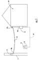
- FIG. 1schematically illustrates two different methods for routing fiber optic cables to a premises 19 .
- FIG. 1shows a first method of routing a cable 10 to premises 19 in an aerial application and a second method using a cable 10 ′ routed to premises 19 in a buried application.
- cable 10has a first end 10 a that is attached at a first interface device 12 located on pole 11 and a second end 10 b that is routed to an interface device 14 at premises 19 .
- the cableis terminated and attached with a clamp such as a P-clamp positioned at a tie point 19 a of premises 19 .
- the fiber optic cableIn the aerial application, the fiber optic cable must be able to carry a predetermined tensile load and also withstand wind and ice loading.
- the first and second ends of cable 10 ′are respectively routed to pedestal 18 and connected to interface device 16 and routed and connected to interface device 14 .
- the cableIn some buried cable applications, the cable is required to withstand the tensile load associated with pulling the cable through a duct.
- Conventional outdoor cablesuse rigid strength elements having relatively large diameters for carrying tensile loads and inhibiting shrinkage of the cable such as a steel or a glass reinforced plastic rod.
- these relatively large rigid strength membersmake the cable very stiff and relatively large, but the cable designs preserve optical performance in the outdoor environment.
- the conventional outdoor cableswere designed to be stiff and inhibit bending, thereby protecting the optical fibers therein.
- these conventional outdoor cablesdramatically increased the bending radius of the cable and when coiled the strength members act like a coiled spring that wants to unwind. Consequently, these conventional outdoor cables are difficult for the craft to handle in the field and as well as being difficult to work with in factory because the rigid strength members.
- Cableshave used other strength members such as conventional fiberglass yarns, but they require a relatively large number of conventional yarns and provide little or no anti-buckling strength compared with rigid strength members. Additionally, these types of cable may not withstand the rigors of the outdoor environment with the desired level of reliability. Moreover, the use of a relatively large number of conventional fiberglass yarns increases the manufacturing complexity along with cost of the cable. Thus, the prior art cables do not meet all of the requirements for a drop cable that is suitable for routing optical waveguides to the subscriber.
- FIG. 1schematically depicts a portion of an optical communication network for providing fiber to the subscriber at location ‘x’ (FTTx).
- FIG. 2is a cross-sectional view of a fiber optic cable according to the present invention.
- FIG. 3is a cross-sectional view of another fiber optic cable according to the present invention.
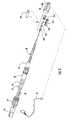
- FIG. 4is an assembled perspective view of the preconnectorized fiber optic drop cable according to the present invention.
- FIG. 5is an exploded view of the preconnectorized fiber optic drop cable of FIG. 4 .
- FIGS. 5 a and 5 brespectively are a perspective view and a sectional view of the shroud of FIG. 4 .
- FIG. 6 ais a perspective view of the cable of FIG. 5 prepared for connectorization.
- FIG. 6 bis a perspective view of one half-shell of the crimp housing of FIG. 5 .
- FIG. 6 cshows a portion of the connector assembly of FIG. 4 attached to the cable and positioned within the half-shell of FIG. 6 b.
- FIG. 6 dshows the partially assembly crimp assembly being attached to the cable.
- FIG. 2depicts a cross-sectional view of an exemplary fiber optic cable 20 according to the present invention suitable for the rigors of the outdoor environment.
- Fiber optic cable 20is intended for applications that route optical fibers to the premises of the subscriber or to close to the subscriber such as to the curb; however, cables according to the present invention can have other applications.
- Optical fiber cable 20includes at least one optical fiber 22 , a buffer tube 24 , a first strength assembly 26 , a second strength assembly 28 , and a cable jacket 29 .
- first and second strength assemblies 26 , 28use two different types of strength elements, namely, at least one strength component 26 a , 28 a and a plurality of strength members 26 b , 28 b .
- strength componentmeans a strength element that has anti-buckling strength such as a glass-reinforced plastic (grp) rod and “strength member” means a strength element that essentially lacks anti-buckling strength such as aramid fibers, glass rovings, and/or other suitable tensile yarns.
- grpglass-reinforced plastic
- first and second strength assemblies 26 , 28are advantageous because besides providing the necessary tensile strength for the fiber optic cables, they allow for greater cable flexibility while still providing the necessary anti-buckling characteristics required for outdoor applications. Cable flexibility is desired in cables intended for subscriber applications because, for instance, it allows for coiling and storing excess cable length and makes the cable easier to route and work with for both the craftsman and factory personnel.
- strength assemblies 26 , 28are generally disposed on opposite sides of buffer tube 24 , thereby imparting a preferential bend characteristic to the cable.
- strength assemblies 26 , 28are arranged so that the respective plurality of strength members 26 b , 28 b are radially disposed about at least half of a circumference of the respective strength components 26 a , 28 a .
- the plurality of strength membersare arranged so that they are radially disposed about the majority, if not the entire, circumference of the strength member.
- Strength components 26 a , 28 a of respective strength assemblies 26 , 28provide fiber optic cable 20 with the majority of its anti-buckling strength along with other characteristic that preserve optical performance.
- strength components 26 a , 28 agenerally resist the shrinking of cable jacket 29 during temperature variations, generally inhibit bending of the cable, and provide tensile strength.
- strength components 26 a , 28 aare not intended to carry the entire tensile load of the cable and are selected to allow a desired degree of bending, thereby making the cable suitable for subscriber applications where the appropriate flexibility is required.
- Strength components 26 a , 28 apreferably are dielectric rods of an all dielectric fiber optic cable design.
- strength componentsare glass-reinforced plastic (grp) rods having a diameter of about 1 mm or less, but other suitable strength component materials, shapes, and/or sizes are possible.
- suitable materials for strength componentsinclude conductive wires such as steel and copper.
- Strength members 26 b , 28 b of respective strength assemblies 26 , 28provide tensile strength to fiber optic cable 20 while still allowing flexibility since the strength members are rovings that generally speaking lack anti-buckling characteristics. In other words, strength members 26 b , 28 b generally provide tensile strength while allowing bending of the cable. Consequently, fiber optic cables according to the present invention balance the strength element characteristics of the strength components and strength members, thereby preserving optical performance in the outdoor environment while providing the desired flexibility and handling characteristics for ease of use in subscriber applications.
- the plurality of strength members 26 b , 28 bare fiberglass yarns or rovings that at least partially contact the respective strength components. Of course, other suitable strength component materials, shapes, and/or sizes are possible.
- strength members 26 b , 28 binclude a matrix material that promotes adhesion to cable jacket 29 such as RPLPE ARAGLASS available from NEPTCO, Inc. of Pawtucket, R.I.
- strength memberscan include a water-swellable component for blocking the migration of water in the cable.
- Optical waveguide 22is preferably a single-mode optical fiber having a tight-buffer layer (not numbered) formed from a polymer or a UV material; however, other types or configurations of optical fibers can be used.
- optical fibers 22can be multi-mode, pure-mode, erbium doped, polarization-maintaining fiber, plastic, other suitable types of light waveguides, and/or combinations thereof.
- each optical fiber 22can include a silica-based core that is operative to transmit light and is surrounded by a silica-based cladding having a lower index of refraction than the core. Additionally, one or more coatings can be applied to optical fiber 25 during manufacture for protecting the cladding.
- a soft primary coatingsurrounds the cladding, and a relatively rigid secondary coating surrounds the primary coating.
- the coatingcan also include an identifying means such as ink or other suitable indicia for identification and/or an anti-adhesion agent that inhibits the removal of the identifying means.
- optical waveguide 22can have other configurations such being included in a ribbon or a bundle. Suitable optical fibers are commercially available from Corning Incorporated of Corning, N.Y.
- Buffer tube 24is preferably constructed of a polymeric material and is suitably dimensioned for receiving the optical waveguides therein. However, other suitable materials and shapes can be used for buffer tube 24 . Buffer tube 24 of the present invention can also include additives for improving flame-retardance; however, any other suitable additives such as for processing can be used. As depicted in FIG. 2 , at least a portion of strength components 26 a , 28 a contact buffer tube 24 . This construction ensures the location of the strength components 26 a , 28 a for connectorization purposes and generally results in a cable with a relatively small footprint, but other configurations are possible such as water-swellable tape wrapped about buffer tube 24 . Additionally, buffer tube 24 can have other suitable components or features such as a water-swellable material thereon or a ripcord within a tube wall.
- fiber optic cable 20includes at least one water-swellable component therein for inhibiting the migration of water along the cable.
- fiber optic cable 20includes at least one, and preferably, a plurality of water-swellable yarns or threads 25 disposed within buffer tube 24 , but the use of a water-swellable powder or coating is also possible.
- Water-swellable yarns 25can serve the function of water-blocking and also act as a coupling element for the optical waveguide.
- a degree of coupling of the optical waveguide with a portion of the cableis generally desirable for inhibiting optical waveguide 22 from migrating along the tube or cavity and/or inhibiting the transfer of forces from the optical waveguide to the optical connector.
- Water-swellable yarns 25can at least intermittently couple optical waveguide 22 with buffer tube 24 .
- water-swellable yarns 25have an excess length compared with optical waveguide 22 , thereby aiding with coupling. Coupling of optical waveguide 22 is achievable in other manners using other suitable coupling elements.
- tube 24may include other coupling elements such as a thixotropic material such as a grease or gel, a water-swellable tape, a foam tape with or without a water-blocking characteristic, or other like materials that may couple intermittently or continuously along the optical waveguide.
- Cable jacket 29is preferably constructed from a suitable polymeric material for protecting the cable from the rigors of the outdoor environment. Cable jacket 29 generally surrounds buffer tube 24 housing optical waveguide 22 and strength assemblies 26 , 28 . As depicted, fiber optic cable 20 has a generally flat cross-section, but other suitable cross-section are possible. Moreover, cable jacket 29 can include ripcords embedded therein or other preferential tear portions for aiding the craft in opening the cable for fiber access. Additionally, cable jacket 29 can include a toning lobe (not shown) having a conductive wire embedded therein for locating the cable in buried environments.
- FIG. 3depicts a fiber optic cable 30 , which is another embodiment according to the present invention.
- Fiber optic cable 30is a tubeless cable design that includes at least one optical fiber 22 , a plurality of water-blocking yarns 25 , strength assemblies 26 ′, 28 ′, and cable jacket 39 .
- Fiber optic cable 30is a tubeless cable design that excludes a buffer tube within a cavity 37 of cable jacket 39 .
- the plurality of strength members 26 b ′, 28 b ′ of respective strength assemblies 26 ′, 28 ′are arranged so that they are radially disposed about the majority, and nearly the entire, circumference of respective strength members 26 a ′, 28 a ′.
- the strength members and/or strength componentsin other suitable arrangements such as discrete placements of the strength components and strength assembly; rather, than as a strength assembly.
- Cavity 37 of cable jacket 39includes tight-buffered optical fiber 22 and a plurality of water-blocking yarns 25 .
- water-blocking yarnsare multi-functional since they inhibit the migration of water and act as a coupling element for optical waveguide 22 .
- Tight-buffered optical fibershould not be confused with optical fiber(s) disposed in a buffer tube.
- buffer tubestypically include one or more optical fibers disposed therein that float in a water-blocking grease or the like.
- buffer tubestypically have a relatively large inner diameter compared with the outer diameter of the optical fiber(s) therein.
- a buffered optical fibersuch as a tight-buffered fiber typically includes a single optical fiber having a buffer layer with an inner diameter that is generally speaking closely matched to the outer diameter of the optical fiber and coupled thereto.
- cable jacket 39includes a profile that inhibits the transfer of clamping forces to the portion of the cable about cavity 37 and directs the clamping forces to the strength assemblies.
- cable jacket 39includes a hour-glass shaped cross-section where a maximum thickness, i.e., the hips, occurs adjacent to at least one of the strength assemblies and preferably occurs adjacent to both strength assemblies 26 ′, 28 ′.
- the cross-section of cable jacket 39includes a minimum thickness, i.e., a waist, adjacent to the cavity 37 of cable jacket, thereby inhibiting the transfer of clamping forces to this area and protecting optical fiber 22 .
- the concepts of cable jacket cross-sectionmay be applied to cable designs other than tubeless.
- FIG. 4depicts a perspective view of one end of an exemplary preconnectorized fiber optic cable assembly 40 using fiber optic cable 20 and an optical plug connector 50 using a connector assembly 52 of the SC type.
- other types of connector assembliessuch as LC, FC, ST, MT, and MT-RJ are contemplated by the present invention by using a suitable crimp housing.
- optical plug connector 50merely crimps to strength components 26 a , 28 b , but other suitable arrangements crimping arrangements contemplated by the present invention.
- FIG. 5depicts an exploded view of preconnectorized cable 100 showing cable 20 and plug connector 50 .
- plug connector 50includes an industry standard SC type connector assembly 52 having a connector body 52 a , a ferrule 52 b in a ferrule holder (not numbered), a spring 52 c , and a spring push 52 d .
- Plug connector 50also includes a crimp assembly (not numbered) that includes a crimp housing having at least one half-shell 55 a and a crimp band 54 , a shroud 60 having an O-ring 59 , a coupling nut 64 , a cable boot 66 , a heat shrink tube 67 , and a protective cap 68 secured to boot 66 by a wire assembly 69 .
- a crimp assembly(not numbered) that includes a crimp housing having at least one half-shell 55 a and a crimp band 54 , a shroud 60 having an O-ring 59 , a coupling nut 64 , a cable boot 66 , a heat shrink tube 67 , and a protective cap 68 secured to boot 66 by a wire assembly 69 .
- plug connector 50are formed from a suitable polymer.
- the polymeris a UV stabilized polymer such as ULTEM 2210 available from GE Plastics; however, other suitable materials are possible. For instance, stainless steel or any other suitable metal may be used for various components.
- the crimp assemblyincludes crimp housing 55 and crimp band 54 .
- Crimp housing 55has two half-shells 55 a that are held together by crimp band 54 when the preconnectorized cable is assembled.
- the term half-shellis used, it is to be understood that it means suitable shells and includes shells that are greater than or less than half of the crimp housing.
- Crimp band 54is preferably made from brass, but other suitable crimpable materials may be used.
- Crimp housing 55is configured for securing connector assembly 52 as well as providing strain relief to cable 20 . This advantageously results in a relatively compact connector arrangement using fewer components.
- the crimp assemblyallows preconnectorized cable 100 to be assembled quickly and easily.
- connector body 52 amay be integrally molded into crimp housing 55 in a ST type configuration so that a twisting motion of the crimp housing secures the ST-type connector with a complementary mating receptacle.
- FIGS. 6 a – 6 ddepict several steps during the process of attaching the crimp assembly to cable 20 .
- FIG. 6 ashows cable 20 having strength members 26 b , 28 b (not visible) and water-swellable yarns 25 (not visible) cut flush with the stripped back jacket 29 , thereby exposing the two strength components 26 a , 28 a along with buffer tube 24 and optical fiber 22 from the end of cable 20 .
- FIG. 6 bshows the inner surface of one half-shell 55 a . In this case, only one half-shell 55 a is illustrated since two symmetrical half-shells are used for both halves of crimp housing 55 . In other embodiments there may be a first half-shell and a second half-shell, which are different. For instance, one half-shell may have two alignment pins, rather than each half-shell having a single alignment pin.
- half-shell 55 aincludes a first end 55 b for securing connector assembly 52 and a second end 55 c that provides strain relief.
- a longitudinal axis A—Ais formed between first end 55 b and second end 55 c near the center of crimp housing 55 , through which half of a longitudinal passage is formed.
- optical fiber 22passes through the longitudinal passage and is held in a bore of ferrule 52 b .
- half-shell 55 aincludes a cable clamping portion 56 and a connector assembly clamping portion 57 .
- Cable clamping portion 56has two outboard half-pipe passageways 56 a and a central half-pipe passageway 56 b that is generally disposed along longitudinal axis A—A.
- Half-pipe passageways 56 a and 56 bpreferably include at least one rib 56 c for securely clamping optical component 42 and strength components 44 after crimp band 54 is crimped, thereby completing the crimp assembly.
- half-pipe passageways 56 a and 56 bare sized for the strength elements, in this case, strength components of cable 20 , but the passageways can be sized for different crimping/cable configurations.
- half-shell 55 ahas a connector assembly clamping portion 57 that is sized for attaching connector assembly 52 .
- connector assembly clamping portion 57has a half-pipe passageway 57 a that opens into and connects central half-pipe passageway 56 b and a partially rectangular passageway 57 b .
- Half-pipe passageway 57 ais sized for securing spring push 52 d and may include one or more ribs for that purpose.
- Rectangular passageway 57 bholds a portion of connector body 52 a therein and inhibits the rotation between connector assembly 52 and the crimp assembly.
- FIG. 6 cdepicts prepared cable 20 of FIG. 6 a having connector assembly 52 attached and positioned in a first half-shell 55 a .
- FIG. 6 dshows both half-shells 55 a of crimp housing 55 disposed about cable 20 before crimp band 54 is installed thereover. Additionally, half-shells may include one or more bores 56 d that lead to one of half-pipe passageways 56 a or 56 b . Bores 56 d allow for inserting an adhesive or epoxy into the crimp housing 55 , thereby providing a secure connection for strain relief.
- crimp housing 55When fully assembled the crimp assembly fits into shroud 60 . Additionally, crimp housing 55 is keyed to direct the insertion of the crimp assembly into shroud 60 .
- half-shells 55 ainclude planar surfaces 57 e ( FIG. 6 d ) on opposites sides of crimp housing 55 to inhibit relative rotation between crimp housing 55 and shroud 60 .
- the crimp assemblymay be keyed to the shroud using other configurations such as a complementary protrusion/groove or the like.
- Shroud 60has a generally cylindrical shape with a first end 60 a and a second end 60 b .
- Shroudgenerally protects connector assembly 52 and in preferred embodiments also keys plug connector 50 with a respective mating receptacle (not shown).
- shroud 60includes a through passageway between first and second ends 60 a and 60 b .
- the passageway of shroud 60is keyed so that crimp housing 54 is inhibited from rotating when plug connector 50 is assembled.
- the passagewayhas an internal shoulder (not numbered) that inhibits the crimp assembly from being inserted beyond a predetermined position.
- first end 60 a of shroud 60includes at least one opening (not numbered) defined by shroud 60 .
- the at least one openingextends from a medial portion of shroud 60 to first end 60 a .
- shroud 60includes a pair of openings on opposite sides of first end 60 a , thereby defining alignment portions or fingers 61 a , 61 b .
- alignment fingers 61 a , 61 bmay extend slightly beyond connector assembly 52 , thereby protecting the same. As shown in FIG.
- alignment fingers 61 a , 61 bhave different shapes so plug connector 50 and the receptacle only mate in one orientation.
- this orientationis marked on shroud 60 using alignment indicia 60 c so that the craftsman can quickly and easily mate preconnectorized cable 100 with the receptacle.
- alignment indicia 60 cis an arrow molded into the top alignment finger of shroud 60 , however, other suitable indicia may be used.
- the arrowis aligned with complimentary alignment indicia disposed on the receptacle, thereby allowing the craftsman to align indicia so that alignment fingers 61 a , 61 b can be correcting seated into the complimentary receptacle. Thereafter, the craftsman engages the external threads of coupling nut 64 with the complimentary internal threads of receptacle to make the optical connection.
- a medial portion of shroud 60has a groove 62 for seating an O-ring 59 .
- O-ring 59provides a weatherproof seal between plug connector 50 and the receptacle or protective cap 68 .
- the medial portionalso includes a shoulder 60 d that provides a stop for coupling nut 64 .
- Coupling nut 64has a passageway sized so that it fits over the second end 60 b of shroud 60 and easily rotates about the medial portion of shroud 60 . In other words, coupling nut 64 cannot move beyond shoulder 60 d , but coupling nut 64 is able to rotate with respect to shroud 60 .
- Second end 60 b of shroud 60includes a stepped down portion having a relatively wide groove (not numbered).
- This stepped down portion and grooveare used for securing heat shrink tubing 67 .
- Heat shrink tubing 67is used for weatherproofing the preconnectorized cable. Specifically, the stepped down portion and groove allow for the attachment of heat shrink tubing 67 to the second end 60 b of shroud 60 . The other end of heat shrink tubing 67 is attached to cable jacket 29 , thereby inhibiting water from entering plug connector 50 .
- boot 66is slid over heat shrink tubing 67 and a portion of shroud 60 .
- Boot 66is preferably formed from a flexible material such as KRAYTON. Heat shrink tubing 67 and boot 66 generally inhibit kinking and provide bending strain relief to the cable near plug connector 50 .
- Boot 66has a longitudinal passageway (not visible) with a stepped profile therethrough. The first end of the boot passageway is sized to fit over the second end of shroud 60 and heat shrink tubing 67 . The first end of the boot passageway has a stepped down portion sized for cable 20 and the heat shrink tubing 67 and acts as stop for indicating that the boot is fully seated.
- coupling nut 64is slid up to shoulder 60 c so that wire assembly 69 can be secured to boot 66 .
- a first end of wire assembly 69is positioned about groove 66 a on boot 66 and wire 69 a is secured thereto using a first wire crimp (not numbered).
- coupling nut 64is captured between shoulder 60 c of shroud 60 and wire assembly 69 on boot 66 . This advantageously keeps coupling nut 64 in place by preventing it from sliding past wire assembly 69 down onto cable 40 .
- wire assembly 69is secured to protective cap 68 using a second wire crimp (not numbered). Consequently, protective cap 68 is prevented from being lost or separated from preconnectorized cable 100 .
- wire assembly 69is attached to protective cap 68 at an eyelet 68 a . Eyelet 68 a is also useful for attaching a fish-tape so that preconnectorized cable 100 can be pulled through a duct.
- Protective cap 68has internal threads for engaging the external threads of coupling nut 64 .
- O-ring 59provides a weatherproof seal between plug connector 50 and protective cap 68 when installed. When threadly engaged, protective cap 68 and coupling nut 64 may rotate with respect to the remainder of preconectorized cable 100 , thus inhibiting torsional forces during pulling.
Landscapes
- Physics & Mathematics (AREA)
- General Physics & Mathematics (AREA)
- Optics & Photonics (AREA)
- Mechanical Coupling Of Light Guides (AREA)
- Light Guides In General And Applications Therefor (AREA)
Abstract
Description
Claims (22)
Priority Applications (1)
| Application Number | Priority Date | Filing Date | Title |
|---|---|---|---|
| US11/020,778US7079734B2 (en) | 2004-12-22 | 2004-12-22 | Fiber optic drop cables suitable for fiber to the subscriber applications |
Applications Claiming Priority (1)
| Application Number | Priority Date | Filing Date | Title |
|---|---|---|---|
| US11/020,778US7079734B2 (en) | 2004-12-22 | 2004-12-22 | Fiber optic drop cables suitable for fiber to the subscriber applications |
Publications (2)
| Publication Number | Publication Date |
|---|---|
| US20060133748A1 US20060133748A1 (en) | 2006-06-22 |
| US7079734B2true US7079734B2 (en) | 2006-07-18 |
Family
ID=36595863
Family Applications (1)
| Application Number | Title | Priority Date | Filing Date |
|---|---|---|---|
| US11/020,778Expired - Fee RelatedUS7079734B2 (en) | 2004-12-22 | 2004-12-22 | Fiber optic drop cables suitable for fiber to the subscriber applications |
Country Status (1)
| Country | Link |
|---|---|
| US (1) | US7079734B2 (en) |
Cited By (32)
| Publication number | Priority date | Publication date | Assignee | Title |
|---|---|---|---|---|
| US20070047884A1 (en)* | 2005-08-25 | 2007-03-01 | Draka Comteq B.V. | Fiber optic cable with a concave surface |
| US20080080817A1 (en)* | 2000-05-26 | 2008-04-03 | Melton Stuart R | Fiber optic drop cables and preconnectorized assemblies having toning portions |
| US20090041411A1 (en)* | 2000-05-26 | 2009-02-12 | Melton Stuart R | Fiber Optic Drop Cables and Preconnectorized Assemblies |
| US20090148101A1 (en)* | 2007-12-11 | 2009-06-11 | Yu Lu | Hardened Fiber Optic Connection System with Multiple Configurations |
| US7572065B2 (en) | 2007-01-24 | 2009-08-11 | Adc Telecommunications, Inc. | Hardened fiber optic connector |
| US7591595B2 (en) | 2007-01-24 | 2009-09-22 | Adc Telelcommunications, Inc. | Hardened fiber optic adapter |
| US20100034503A1 (en)* | 2003-09-22 | 2010-02-11 | Luc Milette | Keyed fibre optic connector |
| US20100322568A1 (en)* | 2009-05-19 | 2010-12-23 | Adc Telecommunications, Inc. | Mechanical interface between a fiber optic cable and a fiber optic connector |
| US20110135268A1 (en)* | 2009-11-25 | 2011-06-09 | Adc Telecommunications, Inc. | Cable pulling assembly |
| USRE42522E1 (en) | 2003-09-08 | 2011-07-05 | Adc Telecommunications, Inc. | Ruggedized fiber optic connection |
| US8761559B1 (en) | 2006-05-11 | 2014-06-24 | Corning Cable Systems Llc | Fiber optic distribution cables and structures therefor |
| US8989542B2 (en) | 2008-07-31 | 2015-03-24 | Corning Optical Communications LLC | Optical fiber assemblies having a powder or powder blend at least partially mechanically attached |
| US9239441B2 (en) | 2000-05-26 | 2016-01-19 | Corning Cable Systems Llc | Fiber optic drop cables and preconnectorized assemblies having toning portions |
| US9477057B2 (en) | 2005-07-29 | 2016-10-25 | Corning Optical Communications LLC | Fiber optic cables and assemblies |
| US9684144B2 (en) | 2012-09-28 | 2017-06-20 | Commscope Technologies Llc | Rapid deployment packaging for optical fiber |
| US9885847B2 (en)* | 2009-05-08 | 2018-02-06 | Commscope Technologies Llc | Cable pulling assembly |
| US10281005B2 (en) | 2015-05-29 | 2019-05-07 | Commscope Technologies Llc | Cable pulling assembly |
| US10359577B2 (en) | 2017-06-28 | 2019-07-23 | Corning Research & Development Corporation | Multiports and optical connectors with rotationally discrete locking and keying features |
| US10379298B2 (en) | 2017-06-28 | 2019-08-13 | Corning Research & Development Corporation | Fiber optic connectors and multiport assemblies including retention features |
| US10444443B2 (en) | 2013-06-27 | 2019-10-15 | CommScope Connectivity Belgium BVBA | Fiber optic cable anchoring device for use with fiber optic connectors and methods of using the same |
| US10514521B2 (en) | 2008-08-15 | 2019-12-24 | Corning Optical Communications LLC | Optical fiber assemblies, and methods and apparatus for the manufacture thereof |
| US11187859B2 (en) | 2017-06-28 | 2021-11-30 | Corning Research & Development Corporation | Fiber optic connectors and methods of making the same |
| US11294133B2 (en) | 2019-07-31 | 2022-04-05 | Corning Research & Development Corporation | Fiber optic networks using multiports and cable assemblies with cable-to-connector orientation |
| US11536921B2 (en) | 2020-02-11 | 2022-12-27 | Corning Research & Development Corporation | Fiber optic terminals having one or more loopback assemblies |
| US11604320B2 (en) | 2020-09-30 | 2023-03-14 | Corning Research & Development Corporation | Connector assemblies for telecommunication enclosures |
| US11686913B2 (en) | 2020-11-30 | 2023-06-27 | Corning Research & Development Corporation | Fiber optic cable assemblies and connector assemblies having a crimp ring and crimp body and methods of fabricating the same |
| US11880076B2 (en) | 2020-11-30 | 2024-01-23 | Corning Research & Development Corporation | Fiber optic adapter assemblies including a conversion housing and a release housing |
| US11927810B2 (en) | 2020-11-30 | 2024-03-12 | Corning Research & Development Corporation | Fiber optic adapter assemblies including a conversion housing and a release member |
| US11994722B2 (en) | 2020-11-30 | 2024-05-28 | Corning Research & Development Corporation | Fiber optic adapter assemblies including an adapter housing and a locking housing |
| US12019279B2 (en) | 2019-05-31 | 2024-06-25 | Corning Research & Development Corporation | Multiports and other devices having optical connection ports with sliding actuators and methods of making the same |
| US12271040B2 (en) | 2017-06-28 | 2025-04-08 | Corning Research & Development Corporation | Fiber optic extender ports, assemblies and methods of making the same |
| US12372727B2 (en) | 2020-10-30 | 2025-07-29 | Corning Research & Development Corporation | Female fiber optic connectors having a rocker latch arm and methods of making the same |
Families Citing this family (13)
| Publication number | Priority date | Publication date | Assignee | Title |
|---|---|---|---|---|
| US7186038B2 (en)* | 2003-12-29 | 2007-03-06 | Adc Telecommunications, Inc. | Telecommunications connector protective device |
| US7406232B2 (en) | 2006-08-31 | 2008-07-29 | Corning Cable Systems Llc | Non-round fiber optic cable having improved major axis crush resistance |
| US20080193092A1 (en)* | 2007-02-13 | 2008-08-14 | Julian Latelle Greenwood | Fiber optic cables having a coupling agent |
| US7744287B2 (en)* | 2007-09-05 | 2010-06-29 | Adc Telecommunications, Inc. | Connector enclosure |
| US8385712B2 (en)* | 2008-02-29 | 2013-02-26 | Adc Telecommunications, Inc. | Cable pulling assembly |
| US8412017B2 (en)* | 2009-05-13 | 2013-04-02 | Adc Telecommunications, Inc. | Cable pulling assembly |
| AU2011100108A4 (en)* | 2011-01-25 | 2011-03-03 | Corning Cable Systems Llc | A fiber optic drop cable assembly |
| US9435978B1 (en)* | 2012-06-14 | 2016-09-06 | Superior Essex Communications Lp | Water-resistant optical fiber cables |
| US11300746B2 (en) | 2017-06-28 | 2022-04-12 | Corning Research & Development Corporation | Fiber optic port module inserts, assemblies and methods of making the same |
| US11668890B2 (en) | 2017-06-28 | 2023-06-06 | Corning Research & Development Corporation | Multiports and other devices having optical connection ports with securing features and methods of making the same |
| EP3805827B1 (en) | 2019-10-07 | 2025-07-30 | Corning Research & Development Corporation | Fiber optic terminals and fiber optic networks having variable ratio couplers |
| US11650388B2 (en) | 2019-11-14 | 2023-05-16 | Corning Research & Development Corporation | Fiber optic networks having a self-supporting optical terminal and methods of installing the optical terminal |
| US11947167B2 (en) | 2021-05-26 | 2024-04-02 | Corning Research & Development Corporation | Fiber optic terminals and tools and methods for adjusting a split ratio of a fiber optic terminal |
Citations (33)
| Publication number | Priority date | Publication date | Assignee | Title |
|---|---|---|---|---|
| US4317000A (en)* | 1980-07-23 | 1982-02-23 | The United States Of America As Represented By The Secretary Of The Navy | Contrahelically laid torque balanced benthic cable |
| US4467138A (en) | 1983-01-17 | 1984-08-21 | Gk Technologies, Inc. | Plural conductor communication wire |
| US4729628A (en)* | 1986-11-14 | 1988-03-08 | Siecor Corporation | Fiber optic dropwire |
| US4761053A (en) | 1985-08-28 | 1988-08-02 | American Telephone And Telegraph Company, At&T Bell Laboratories | Communications transmission media |
| US4776664A (en) | 1987-08-20 | 1988-10-11 | Masahiko Okura | Optical telephone wire |
| US4787705A (en) | 1986-09-05 | 1988-11-29 | Fujikura Ltd. | Composite optical fiber and power cable |
| US4892382A (en) | 1988-09-26 | 1990-01-09 | Siecor Corporation | Dielectric optical drop cable |
| US5050957A (en) | 1990-04-27 | 1991-09-24 | At&T Bell Laboratories | Optical fiber service cable |
| US5121458A (en)* | 1991-04-05 | 1992-06-09 | Alcatel Na Cable Systems, Inc. | Preterminated fiber optic cable |
| US5180890A (en) | 1991-03-03 | 1993-01-19 | Independent Cable, Inc. | Communications transmission cable |
| US5233678A (en)* | 1991-06-03 | 1993-08-03 | Sumitomo Electric Industries, Ltd. | Optical fiber cable including plural multifiber optical units |
| US5369720A (en)* | 1992-10-21 | 1994-11-29 | Northern Telecom Limited | Optical fibre cable incorporating a stack of fibre ribbon elements |
| US5509097A (en)* | 1994-04-07 | 1996-04-16 | Pirelli Cable Corporation | Optical fiber core and cable with reinforced buffer tube loosely enclosing optical fibers |
| US5561729A (en) | 1995-05-15 | 1996-10-01 | Siecor Corporation | Communications cable including fiber reinforced plastic materials |
| US5566266A (en) | 1995-01-26 | 1996-10-15 | Siecor Corporation | Optical fiber service cable |
| US5651081A (en) | 1994-06-10 | 1997-07-22 | Commscope, Inc. | Composite fiber optic and electrical cable and associated fabrication method |
| US6188821B1 (en) | 1998-06-22 | 2001-02-13 | Siecor Operations, Llc | Apparatuses and methods for use in the making of a self-supporting fiber optic cable |
| US6249629B1 (en) | 1998-12-10 | 2001-06-19 | Siecor Operations, Llc | Robust fiber optic cables |
| US6249628B1 (en)* | 1999-06-10 | 2001-06-19 | Siecor Operations, Llc | Fiber optic cable units |
| US6256438B1 (en) | 1999-10-29 | 2001-07-03 | Siecor Operations, Llc | Fiber optic drop cable |
| US6311000B1 (en) | 1996-02-13 | 2001-10-30 | Siemens Aktiengesellschaft | Optical cable and an apparatus for manufacturing the optical cable |
| US6356690B1 (en) | 1999-10-20 | 2002-03-12 | Corning Cable Systems Llc | Self-supporting fiber optic cable |
| US6400873B1 (en) | 2000-03-31 | 2002-06-04 | Corning Cable Systems Llc | Fiber optic cable having a strength member |
| US6487345B1 (en) | 2000-01-12 | 2002-11-26 | Fitel Usa Corp. | Communication cable having reduced jacket shrinkage |
| US6487347B2 (en) | 1997-03-24 | 2002-11-26 | Corning Cable Systems Llc | Indoor/outdoor optical cables |
| US6501888B2 (en) | 1999-09-16 | 2002-12-31 | Corning Cable Systems Llc | Fiber optic cables with strength members and an apparatus for making the same |
| US20030026559A1 (en)* | 2001-05-15 | 2003-02-06 | Vanvickle Patrick S. | Water-blocked fiber optic ribbon cable |
| US6529663B1 (en) | 2000-07-31 | 2003-03-04 | Corning Cable Systems Llc | Self-supporting fiber optic cable having a support section with a non-uniform jacket |
| US6542674B1 (en) | 2000-08-25 | 2003-04-01 | Corning Cable Systems Llc | Fiber optic cables with strength members |
| US6546175B1 (en) | 2000-05-26 | 2003-04-08 | Corning Cable Systems Llc | Self-supporting fiber optic cable |
| US6563990B1 (en) | 1998-06-22 | 2003-05-13 | Corning Cable Systems, Llc | Self-supporting cables and an apparatus and methods for making the same |
| US6567592B1 (en)* | 2000-09-29 | 2003-05-20 | Corning Cable Systems Llc | Optical cables with flexible strength sections |
| US20040197059A1 (en)* | 2001-05-30 | 2004-10-07 | Luca Castellani | Optical fiber cable with dimensionally stable polymeric component |
- 2004
- 2004-12-22USUS11/020,778patent/US7079734B2/ennot_activeExpired - Fee Related
Patent Citations (34)
| Publication number | Priority date | Publication date | Assignee | Title |
|---|---|---|---|---|
| US4317000A (en)* | 1980-07-23 | 1982-02-23 | The United States Of America As Represented By The Secretary Of The Navy | Contrahelically laid torque balanced benthic cable |
| US4467138A (en) | 1983-01-17 | 1984-08-21 | Gk Technologies, Inc. | Plural conductor communication wire |
| US4761053A (en) | 1985-08-28 | 1988-08-02 | American Telephone And Telegraph Company, At&T Bell Laboratories | Communications transmission media |
| US4787705A (en) | 1986-09-05 | 1988-11-29 | Fujikura Ltd. | Composite optical fiber and power cable |
| US4729628A (en)* | 1986-11-14 | 1988-03-08 | Siecor Corporation | Fiber optic dropwire |
| US4776664A (en) | 1987-08-20 | 1988-10-11 | Masahiko Okura | Optical telephone wire |
| US4892382A (en) | 1988-09-26 | 1990-01-09 | Siecor Corporation | Dielectric optical drop cable |
| US5050957A (en) | 1990-04-27 | 1991-09-24 | At&T Bell Laboratories | Optical fiber service cable |
| US5180890A (en) | 1991-03-03 | 1993-01-19 | Independent Cable, Inc. | Communications transmission cable |
| US5121458A (en)* | 1991-04-05 | 1992-06-09 | Alcatel Na Cable Systems, Inc. | Preterminated fiber optic cable |
| US5233678A (en)* | 1991-06-03 | 1993-08-03 | Sumitomo Electric Industries, Ltd. | Optical fiber cable including plural multifiber optical units |
| US5369720A (en)* | 1992-10-21 | 1994-11-29 | Northern Telecom Limited | Optical fibre cable incorporating a stack of fibre ribbon elements |
| US5509097A (en)* | 1994-04-07 | 1996-04-16 | Pirelli Cable Corporation | Optical fiber core and cable with reinforced buffer tube loosely enclosing optical fibers |
| US5651081A (en) | 1994-06-10 | 1997-07-22 | Commscope, Inc. | Composite fiber optic and electrical cable and associated fabrication method |
| US5566266A (en) | 1995-01-26 | 1996-10-15 | Siecor Corporation | Optical fiber service cable |
| US5561729A (en) | 1995-05-15 | 1996-10-01 | Siecor Corporation | Communications cable including fiber reinforced plastic materials |
| US6311000B1 (en) | 1996-02-13 | 2001-10-30 | Siemens Aktiengesellschaft | Optical cable and an apparatus for manufacturing the optical cable |
| US6487347B2 (en) | 1997-03-24 | 2002-11-26 | Corning Cable Systems Llc | Indoor/outdoor optical cables |
| US6563990B1 (en) | 1998-06-22 | 2003-05-13 | Corning Cable Systems, Llc | Self-supporting cables and an apparatus and methods for making the same |
| US6188821B1 (en) | 1998-06-22 | 2001-02-13 | Siecor Operations, Llc | Apparatuses and methods for use in the making of a self-supporting fiber optic cable |
| US6249629B1 (en) | 1998-12-10 | 2001-06-19 | Siecor Operations, Llc | Robust fiber optic cables |
| US6249628B1 (en)* | 1999-06-10 | 2001-06-19 | Siecor Operations, Llc | Fiber optic cable units |
| US6501888B2 (en) | 1999-09-16 | 2002-12-31 | Corning Cable Systems Llc | Fiber optic cables with strength members and an apparatus for making the same |
| US6356690B1 (en) | 1999-10-20 | 2002-03-12 | Corning Cable Systems Llc | Self-supporting fiber optic cable |
| US6256438B1 (en) | 1999-10-29 | 2001-07-03 | Siecor Operations, Llc | Fiber optic drop cable |
| US6487345B1 (en) | 2000-01-12 | 2002-11-26 | Fitel Usa Corp. | Communication cable having reduced jacket shrinkage |
| US6400873B1 (en) | 2000-03-31 | 2002-06-04 | Corning Cable Systems Llc | Fiber optic cable having a strength member |
| US6546175B1 (en) | 2000-05-26 | 2003-04-08 | Corning Cable Systems Llc | Self-supporting fiber optic cable |
| US6529663B1 (en) | 2000-07-31 | 2003-03-04 | Corning Cable Systems Llc | Self-supporting fiber optic cable having a support section with a non-uniform jacket |
| US6542674B1 (en) | 2000-08-25 | 2003-04-01 | Corning Cable Systems Llc | Fiber optic cables with strength members |
| US6714710B2 (en) | 2000-08-25 | 2004-03-30 | Corning Cable Systems, Llc | Fiber optic cables with strength members |
| US6567592B1 (en)* | 2000-09-29 | 2003-05-20 | Corning Cable Systems Llc | Optical cables with flexible strength sections |
| US20030026559A1 (en)* | 2001-05-15 | 2003-02-06 | Vanvickle Patrick S. | Water-blocked fiber optic ribbon cable |
| US20040197059A1 (en)* | 2001-05-30 | 2004-10-07 | Luca Castellani | Optical fiber cable with dimensionally stable polymeric component |
Non-Patent Citations (1)
| Title |
|---|
| NEPTCO Incorporated "Fiber Optic Cable Components", Apr. 2003. |
Cited By (109)
| Publication number | Priority date | Publication date | Assignee | Title |
|---|---|---|---|---|
| US10114176B2 (en) | 2000-05-26 | 2018-10-30 | Corning Optical Communications LLC | Fiber optic drop cables and preconnectorized assemblies |
| US7785015B2 (en) | 2000-05-26 | 2010-08-31 | Corning Cable Systems Llc | Fiber optic drop cables and preconnectorized assemblies |
| US7467896B2 (en) | 2000-05-26 | 2008-12-23 | Corning Cable Systems Llc | Fiber optic drop cables and preconnectorized assemblies |
| US20090041411A1 (en)* | 2000-05-26 | 2009-02-12 | Melton Stuart R | Fiber Optic Drop Cables and Preconnectorized Assemblies |
| US20090060423A1 (en)* | 2000-05-26 | 2009-03-05 | Melton Stuart R | Fiber Optic Drop Cables and Preconnectorized Assemblies Having Toning Portions |
| US7918609B2 (en) | 2000-05-26 | 2011-04-05 | Corning Cable Systems Llc | Fiber optic drop cables and preconnectorized assemblies |
| US7881576B2 (en) | 2000-05-26 | 2011-02-01 | Corning Cable Systems Llc | Fiber optic drop cables and preconnectorized assemblies |
| US9239441B2 (en) | 2000-05-26 | 2016-01-19 | Corning Cable Systems Llc | Fiber optic drop cables and preconnectorized assemblies having toning portions |
| US20080080817A1 (en)* | 2000-05-26 | 2008-04-03 | Melton Stuart R | Fiber optic drop cables and preconnectorized assemblies having toning portions |
| USRE42522E1 (en) | 2003-09-08 | 2011-07-05 | Adc Telecommunications, Inc. | Ruggedized fiber optic connection |
| US20100034503A1 (en)* | 2003-09-22 | 2010-02-11 | Luc Milette | Keyed fibre optic connector |
| US9971101B2 (en) | 2005-07-29 | 2018-05-15 | Corning Optical Communications LLC | Fiber optic cable assembly |
| US9482837B2 (en) | 2005-07-29 | 2016-11-01 | Corning Cable Systems Llc | Dry fiber optic cables and assemblies |
| US9477057B2 (en) | 2005-07-29 | 2016-10-25 | Corning Optical Communications LLC | Fiber optic cables and assemblies |
| US9494755B2 (en) | 2005-07-29 | 2016-11-15 | Corning Optical Communications LLC | Fiber optic cable assembly |
| US20070047884A1 (en)* | 2005-08-25 | 2007-03-01 | Draka Comteq B.V. | Fiber optic cable with a concave surface |
| US7391944B2 (en)* | 2005-08-25 | 2008-06-24 | Draka Comteq B.V. | Fiber optic cable with a concave surface |
| US8761559B1 (en) | 2006-05-11 | 2014-06-24 | Corning Cable Systems Llc | Fiber optic distribution cables and structures therefor |
| US9341805B2 (en) | 2006-05-11 | 2016-05-17 | Ccs Technology, Inc. | Fiber optic distribution cables and structures therefor |
| US9176292B2 (en) | 2006-05-11 | 2015-11-03 | Ccs Technology, Inc. | Fiber optic distribution cables and structures therefor |
| US9494764B2 (en) | 2006-05-11 | 2016-11-15 | Corning Optical Communications LLC | Fiber optic distribution cables and structures therefor |
| US7572065B2 (en) | 2007-01-24 | 2009-08-11 | Adc Telecommunications, Inc. | Hardened fiber optic connector |
| US12111502B2 (en) | 2007-01-24 | 2024-10-08 | Commscope Technologies Llc | Hardened fiber optic connector |
| US9664862B2 (en) | 2007-01-24 | 2017-05-30 | Commscope Technologies Llc | Hardened fiber optic connector |
| US11409057B2 (en) | 2007-01-24 | 2022-08-09 | Commscope Technologies Llc | Hardened fiber optic connector |
| US10877224B2 (en) | 2007-01-24 | 2020-12-29 | Commscope Technologies Llc | Fiber optic adapter |
| US8770862B2 (en) | 2007-01-24 | 2014-07-08 | Adc Telecommunications, Inc. | Hardened fiber optic connector |
| US7591595B2 (en) | 2007-01-24 | 2009-09-22 | Adc Telelcommunications, Inc. | Hardened fiber optic adapter |
| US7744286B2 (en) | 2007-12-11 | 2010-06-29 | Adc Telecommunications, Inc. | Hardened fiber optic connection system with multiple configurations |
| US11275220B2 (en) | 2007-12-11 | 2022-03-15 | Commscope Technologies Llc | Hardened fiber optic connector compatible with hardened and non-hardened fiber optic adapters |
| US11867950B2 (en) | 2007-12-11 | 2024-01-09 | Commscope Technologies Llc | Hardened fiber optic connector compatible with hardened and non-hardened fiber optic adapters |
| US8414196B2 (en) | 2007-12-11 | 2013-04-09 | Adc Telecommunications, Inc. | Optical fiber connection system with locking member |
| US9482829B2 (en) | 2007-12-11 | 2016-11-01 | Commscope Technologies Llc | Hardened fiber optic connector compatible with hardened and non-hardened fiber optic adapters |
| US8202008B2 (en) | 2007-12-11 | 2012-06-19 | Adc Telecommunications, Inc. | Hardened fiber optic connection system with multiple configurations |
| US7959361B2 (en) | 2007-12-11 | 2011-06-14 | Adc Telecommunications, Inc. | Hardened fiber optic connection system |
| US7942590B2 (en) | 2007-12-11 | 2011-05-17 | Adc Telecommunications, Inc. | Hardened fiber optic connector and cable assembly with multiple configurations |
| US12181718B2 (en) | 2007-12-11 | 2024-12-31 | Commscope Technologies Llc | Hardened fiber optic connector compatible with hardened and non-hardened fiber optic adapters |
| US10746939B2 (en) | 2007-12-11 | 2020-08-18 | Commscope Technologies Llc | Hardened fiber optic connector compatible with hardened and non-hardened fiber optic adapters |
| US7762726B2 (en) | 2007-12-11 | 2010-07-27 | Adc Telecommunications, Inc. | Hardened fiber optic connection system |
| US20090148101A1 (en)* | 2007-12-11 | 2009-06-11 | Yu Lu | Hardened Fiber Optic Connection System with Multiple Configurations |
| US7744288B2 (en) | 2007-12-11 | 2010-06-29 | Adc Telecommunications, Inc. | Hardened fiber optic connector compatible with hardened and non-hardened fiber optic adapters |
| US10101538B2 (en) | 2007-12-11 | 2018-10-16 | Commscope Technologies Llc | Hardened fiber optic connector compatible with hardened and non-hardened fiber optic adapters |
| US8989542B2 (en) | 2008-07-31 | 2015-03-24 | Corning Optical Communications LLC | Optical fiber assemblies having a powder or powder blend at least partially mechanically attached |
| US10514521B2 (en) | 2008-08-15 | 2019-12-24 | Corning Optical Communications LLC | Optical fiber assemblies, and methods and apparatus for the manufacture thereof |
| US20180180832A1 (en)* | 2009-05-08 | 2018-06-28 | Commscope Technologies Llc | Cable pulling assembly |
| US9885847B2 (en)* | 2009-05-08 | 2018-02-06 | Commscope Technologies Llc | Cable pulling assembly |
| US10598886B2 (en)* | 2009-05-08 | 2020-03-24 | Commscope Technologies Llc | Cable pulling assembly |
| US10754102B2 (en) | 2009-05-19 | 2020-08-25 | Commscope Technologies Llc | Mechanical interface between a fiber optic cable and a fiber optic connector |
| US11243359B2 (en) | 2009-05-19 | 2022-02-08 | Commscope Technologies Llc | Mechanical interface between a fiber optic cable and a fiber optic connector |
| US20100322568A1 (en)* | 2009-05-19 | 2010-12-23 | Adc Telecommunications, Inc. | Mechanical interface between a fiber optic cable and a fiber optic connector |
| US10247888B2 (en) | 2009-05-19 | 2019-04-02 | Commscope Technologies Llc | Mechanical interface between a fiber optic cable and a fiber optic connector |
| US8646989B2 (en) | 2009-05-19 | 2014-02-11 | Adc Telecommunications, Inc. | Mechanical interface between a fiber optic cable and a fiber optic connector |
| US9766413B2 (en) | 2009-05-19 | 2017-09-19 | Commscope Technologies Llc | Mechanical interface between a fiber optic cable and a fiber optic connector |
| US20110135268A1 (en)* | 2009-11-25 | 2011-06-09 | Adc Telecommunications, Inc. | Cable pulling assembly |
| US8620129B2 (en) | 2009-11-25 | 2013-12-31 | Adc Telecommunications, Inc. | Cable pulling assembly |
| US9684144B2 (en) | 2012-09-28 | 2017-06-20 | Commscope Technologies Llc | Rapid deployment packaging for optical fiber |
| US12117658B2 (en) | 2013-06-27 | 2024-10-15 | CommScope Connectivity Belgium BVBA | Fiber optic cable anchoring device for use with fiber optic connectors and methods of using the same |
| US10444443B2 (en) | 2013-06-27 | 2019-10-15 | CommScope Connectivity Belgium BVBA | Fiber optic cable anchoring device for use with fiber optic connectors and methods of using the same |
| US10281005B2 (en) | 2015-05-29 | 2019-05-07 | Commscope Technologies Llc | Cable pulling assembly |
| US11493699B2 (en) | 2017-06-28 | 2022-11-08 | Corning Research & Development Corporation | Multifiber fiber optic connectors, cable assemblies and methods of making the same |
| US12379552B2 (en) | 2017-06-28 | 2025-08-05 | Corning Research & Development Corporation | Compact fiber optic connectors, cable assemblies and methods of making the same |
| US11187859B2 (en) | 2017-06-28 | 2021-11-30 | Corning Research & Development Corporation | Fiber optic connectors and methods of making the same |
| US11262509B2 (en) | 2017-06-28 | 2022-03-01 | Corning Research & Development Corporation | Compact fiber optic connectors having multiple connector footprints, along with cable assemblies and methods of making the same |
| US10809463B2 (en) | 2017-06-28 | 2020-10-20 | Corning Research & Development Corporation | Multiports and optical connectors with rotationally discrete locking and keying features |
| US11287581B2 (en) | 2017-06-28 | 2022-03-29 | Corning Research & Development Corporation | Compact fiber optic connectors, cable assemblies and methods of making the same |
| US11287582B2 (en) | 2017-06-28 | 2022-03-29 | Corning Research & Development Corporation | Compact fiber optic connectors, cable assemblies and methods of making the same |
| US12429655B2 (en) | 2017-06-28 | 2025-09-30 | Corning Optical Communications LLC | Multiports having connection ports with associated securing features and methods of making the same |
| US11300735B2 (en) | 2017-06-28 | 2022-04-12 | Corning Research & Development Corporation | Compact fiber optic connectors having multiple connector footprints, along with cable assemblies and methods of making the same |
| US11307364B2 (en) | 2017-06-28 | 2022-04-19 | Corning Research & Development Corporation | Compact fiber optic connectors having multiple connector footprints, along with cable assemblies and methods of making the same |
| US10802228B2 (en) | 2017-06-28 | 2020-10-13 | Corning Research & Development Corporation | Fiber optic connectors and multiport assemblies including retention features |
| US11460646B2 (en) | 2017-06-28 | 2022-10-04 | Corning Research & Development Corporation | Fiber optic connectors and multiport assemblies including retention features |
| US11493700B2 (en) | 2017-06-28 | 2022-11-08 | Corning Research & Development Corporation | Compact fiber optic connectors, cable assemblies and methods of making the same |
| US10605998B2 (en) | 2017-06-28 | 2020-03-31 | Corning Research & Development Corporation | Fiber optic connectors and connectorization employing adhesive admitting adapters |
| US11531168B2 (en) | 2017-06-28 | 2022-12-20 | Corning Research & Development Corporation | Fiber optic connectors having a keying structure and methods of making the same |
| US12379551B2 (en) | 2017-06-28 | 2025-08-05 | Corning Optical Communications LLC | Multiports having connection ports formed in the shell and associated securing features |
| US11536913B2 (en) | 2017-06-28 | 2022-12-27 | Corning Research & Development Corporation | Fiber optic connectors and connectorization employing adhesive admitting adapters |
| US11543600B2 (en) | 2017-06-28 | 2023-01-03 | Corning Research & Development Corporation | Compact fiber optic connectors having multiple connector footprints, along with cable assemblies and methods of making the same |
| US11579377B2 (en) | 2017-06-28 | 2023-02-14 | Corning Research & Development Corporation | Compact fiber optic connectors, cable assemblies and methods of making the same with alignment elements |
| US11215768B2 (en) | 2017-06-28 | 2022-01-04 | Corning Research & Development Corporation | Fiber optic connectors and connectorization employing adhesive admitting adapters |
| US12353024B2 (en) | 2017-06-28 | 2025-07-08 | Corning Research & Development Corporation | Multiports and optical connectors with rotationally discrete locking and keying features |
| US11703646B2 (en) | 2017-06-28 | 2023-07-18 | Corning Research & Development Corporation | Multiports and optical connectors with rotationally discrete locking and keying features |
| US10359577B2 (en) | 2017-06-28 | 2019-07-23 | Corning Research & Development Corporation | Multiports and optical connectors with rotationally discrete locking and keying features |
| US12353025B2 (en) | 2017-06-28 | 2025-07-08 | Corning Optical Communications LLC | Multiports having a connection port insert and methods of making the same |
| US11886017B2 (en) | 2017-06-28 | 2024-01-30 | Corning Research & Development Corporation | Multiports and other devices having connection ports with securing features and methods of making the same |
| US11906792B2 (en) | 2017-06-28 | 2024-02-20 | Corning Research & Development Corporation | Compact fiber optic connectors having multiple connector footprints, along with cable assemblies and methods of making the same |
| US11914198B2 (en) | 2017-06-28 | 2024-02-27 | Corning Research & Development Corporation | Compact fiber optic connectors having multiple connector footprints, along with cable assemblies and methods of making the same |
| US11914197B2 (en) | 2017-06-28 | 2024-02-27 | Corning Research & Development Corporation | Compact fiber optic connectors having multiple connector footprints, along with cable assemblies and methods of making the same |
| US12298568B2 (en) | 2017-06-28 | 2025-05-13 | Corning Research & Development Corporation | Fiber optic connectors and multiport assemblies including retention features |
| US11940656B2 (en) | 2017-06-28 | 2024-03-26 | Corning Research & Development Corporation | Compact fiber optic connectors, cable assemblies and methods of making the same |
| US11966089B2 (en) | 2017-06-28 | 2024-04-23 | Corning Optical Communications, Llc | Multiports having connection ports formed in the shell and associated securing features |
| US12276846B2 (en) | 2017-06-28 | 2025-04-15 | Corning Research & Development Corporation | Compact fiber optic connectors, cable assemblies and methods of making the same |
| US12013578B2 (en) | 2017-06-28 | 2024-06-18 | Corning Research & Development Corporation | Multifiber fiber optic connectors, cable assemblies and methods of making the same |
| US10386584B2 (en) | 2017-06-28 | 2019-08-20 | Corning Research & Development Corporation | Optical connectors with locking and keying features for interfacing with multiports |
| US12271040B2 (en) | 2017-06-28 | 2025-04-08 | Corning Research & Development Corporation | Fiber optic extender ports, assemblies and methods of making the same |
| US12092878B2 (en) | 2017-06-28 | 2024-09-17 | Corning Research & Development Corporation | Fiber optic connectors having a keying structure and methods of making the same |
| US10379298B2 (en) | 2017-06-28 | 2019-08-13 | Corning Research & Development Corporation | Fiber optic connectors and multiport assemblies including retention features |
| US10429593B2 (en) | 2017-06-28 | 2019-10-01 | Corning Research & Development Corporation | Fiber optic connectors and connectorization employing adapter extensions and/or flexures |
| US12174432B2 (en) | 2017-06-28 | 2024-12-24 | Corning Research & Development Corporation | Fiber optic connectors and connectorization employing adhesive admitting adapters |
| US12019279B2 (en) | 2019-05-31 | 2024-06-25 | Corning Research & Development Corporation | Multiports and other devices having optical connection ports with sliding actuators and methods of making the same |
| US11294133B2 (en) | 2019-07-31 | 2022-04-05 | Corning Research & Development Corporation | Fiber optic networks using multiports and cable assemblies with cable-to-connector orientation |
| US11536921B2 (en) | 2020-02-11 | 2022-12-27 | Corning Research & Development Corporation | Fiber optic terminals having one or more loopback assemblies |
| US12019285B2 (en) | 2020-09-30 | 2024-06-25 | Corning Research & Development Corporation | Connector assemblies for telecommunication enclosures |
| US11604320B2 (en) | 2020-09-30 | 2023-03-14 | Corning Research & Development Corporation | Connector assemblies for telecommunication enclosures |
| US12372727B2 (en) | 2020-10-30 | 2025-07-29 | Corning Research & Development Corporation | Female fiber optic connectors having a rocker latch arm and methods of making the same |
| US11994722B2 (en) | 2020-11-30 | 2024-05-28 | Corning Research & Development Corporation | Fiber optic adapter assemblies including an adapter housing and a locking housing |
| US11927810B2 (en) | 2020-11-30 | 2024-03-12 | Corning Research & Development Corporation | Fiber optic adapter assemblies including a conversion housing and a release member |
| US12345927B2 (en) | 2020-11-30 | 2025-07-01 | Corning Research & Development Corporation | Fiber optic adapter assemblies including a conversion housing and a release housing |
| US11880076B2 (en) | 2020-11-30 | 2024-01-23 | Corning Research & Development Corporation | Fiber optic adapter assemblies including a conversion housing and a release housing |
| US11686913B2 (en) | 2020-11-30 | 2023-06-27 | Corning Research & Development Corporation | Fiber optic cable assemblies and connector assemblies having a crimp ring and crimp body and methods of fabricating the same |
Also Published As
| Publication number | Publication date |
|---|---|
| US20060133748A1 (en) | 2006-06-22 |
Similar Documents
| Publication | Publication Date | Title |
|---|---|---|
| US7079734B2 (en) | Fiber optic drop cables suitable for fiber to the subscriber applications | |
| US10114176B2 (en) | Fiber optic drop cables and preconnectorized assemblies | |
| US7918609B2 (en) | Fiber optic drop cables and preconnectorized assemblies | |
| US7467896B2 (en) | Fiber optic drop cables and preconnectorized assemblies | |
| US7111990B2 (en) | Figure-eight preconnectorized fiber optic drop cables and assemblies | |
| US7090406B2 (en) | Preconnectorized fiber optic drop cables and assemblies | |
| US7090407B2 (en) | Preconnectorized fiber optic drop cables and assemblies for efficient deployment | |
| US7184634B2 (en) | Fiber optic drop cables suitable for outdoor fiber to the subscriber applications | |
| US7796853B2 (en) | Fiber optic cables and assemblies for fiber toward the subscriber applications | |
| US20050281510A1 (en) | Fiber optic cable and plug assembly | |
| US7206482B2 (en) | Protective casings for optical fibers |
Legal Events
| Date | Code | Title | Description |
|---|---|---|---|
| AS | Assignment | Owner name:CORNING CABLE SYSTEMS, LLC, NORTH CAROLINA Free format text:ASSIGNMENT OF ASSIGNORS INTEREST;ASSIGNORS:SEDDON, DAVID A.;HURLEY, WILLIAM C.;REEL/FRAME:016126/0952;SIGNING DATES FROM 20041220 TO 20041221 | |
| FPAY | Fee payment | Year of fee payment:4 | |
| FPAY | Fee payment | Year of fee payment:8 | |
| AS | Assignment | Owner name:CCS TECHNOLOGY, INC., DELAWARE Free format text:ASSIGNMENT OF ASSIGNORS INTEREST;ASSIGNOR:CORNING CABLE SYSTEMS LLC;REEL/FRAME:041559/0981 Effective date:20080508 | |
| AS | Assignment | Owner name:CORNING OPTICAL COMMUNICATIONS LLC, NORTH CAROLINA Free format text:MERGER;ASSIGNORS:CCS TECHNOLOGY, INC.;CORNING OPTICAL COMMUNICATIONS BRANDS, INC.;REEL/FRAME:043601/0427 Effective date:20170630 | |
| FEPP | Fee payment procedure | Free format text:MAINTENANCE FEE REMINDER MAILED (ORIGINAL EVENT CODE: REM.) | |
| LAPS | Lapse for failure to pay maintenance fees | Free format text:PATENT EXPIRED FOR FAILURE TO PAY MAINTENANCE FEES (ORIGINAL EVENT CODE: EXP.) | |
| STCH | Information on status: patent discontinuation | Free format text:PATENT EXPIRED DUE TO NONPAYMENT OF MAINTENANCE FEES UNDER 37 CFR 1.362 | |
| FP | Lapsed due to failure to pay maintenance fee | Effective date:20180718 |