US7079012B2 - System and method for distributing broadband communication signals over power lines - Google Patents
System and method for distributing broadband communication signals over power linesDownload PDFInfo
- Publication number
- US7079012B2 US7079012B2US10/763,054US76305404AUS7079012B2US 7079012 B2US7079012 B2US 7079012B2US 76305404 AUS76305404 AUS 76305404AUS 7079012 B2US7079012 B2US 7079012B2
- Authority
- US
- United States
- Prior art keywords
- inductors
- power line
- high frequency
- accordance
- providing
- Prior art date
- Legal status (The legal status is an assumption and is not a legal conclusion. Google has not performed a legal analysis and makes no representation as to the accuracy of the status listed.)
- Expired - Lifetime
Links
Images


Classifications
- H—ELECTRICITY
- H04—ELECTRIC COMMUNICATION TECHNIQUE
- H04B—TRANSMISSION
- H04B3/00—Line transmission systems
- H04B3/54—Systems for transmission via power distribution lines
- H04B3/542—Systems for transmission via power distribution lines the information being in digital form
- H—ELECTRICITY
- H04—ELECTRIC COMMUNICATION TECHNIQUE
- H04B—TRANSMISSION
- H04B3/00—Line transmission systems
- H04B3/54—Systems for transmission via power distribution lines
- H04B3/56—Circuits for coupling, blocking, or by-passing of signals
- H—ELECTRICITY
- H04—ELECTRIC COMMUNICATION TECHNIQUE
- H04B—TRANSMISSION
- H04B2203/00—Indexing scheme relating to line transmission systems
- H04B2203/54—Aspects of powerline communications not already covered by H04B3/54 and its subgroups
- H04B2203/5429—Applications for powerline communications
- H04B2203/5445—Local network
- H—ELECTRICITY
- H04—ELECTRIC COMMUNICATION TECHNIQUE
- H04B—TRANSMISSION
- H04B2203/00—Indexing scheme relating to line transmission systems
- H04B2203/54—Aspects of powerline communications not already covered by H04B3/54 and its subgroups
- H04B2203/5462—Systems for power line communications
- H04B2203/5466—Systems for power line communications using three phases conductors
Definitions
- This inventionrelates to data communications, and more specifically to a broadband communication system employing power transmission lines.
- BOPLbroadband over power lines
- Broadband over power line technologyemploys building and/or overhead power lines to conduct HF and VHF digital signals for allowing computers to connect to the Internet.
- the FCCviews this technology as a competitive Internet access point, and the utilities view the technology as a means to use existing infrastructure to generate additional revenue from something other than power generation and distribution.
- the power linemay act as an antenna that is able to emanate electromagnetic radiation leading to a significant interference to over-the-air radio services.
- power transmission linesmay emit signals having a power of up to 30 microvolts/meter at a distance of 30 meters from the source.
- emission levelscan easily interfere with other overlapping frequency channels, such as those used by Amateur Radio Service.
- the problem with such interferenceis that it affects not only the Amateur Radio community, but also those who employ radio services using High Frequency HF spectrum.
- high frequency signalsare carried over an electric utility power line.
- the high frequency signalmaintains a constant signal power necessary for a satisfactory demodulation.
- the high frequency current signalis reduced so as to reduce the radio frequency radiation emitted from the utility power line.
- a plurality of inductive loadsare installed at selected locations along the utility power line.
- the inductive loadsare clamp-on inductors.
- the inductive loadsare connected in series with the utility line.
- the inductorsare chosen so that their reactance is negligible at the power line frequency, which is about 50 or 60 Hz, and their reactance is significant at High Frequency (HF) band.
- HFHigh Frequency
- the value of the voltage level of the transmitted signalis increased, while the value of the current level of the transmitted signal is decreased. Since the radiation is caused by current I, a reduction in current level leads to a reduction in emitted radiation.
- the inductorsraise the impedance of the power lines, thereby allowing the transfer of power to the lines at a higher voltage and a lower current, than what is required if the inductors were not employed.
- FIG. 1illustrates a system that allows transmission of broadband signals over power lines in accordance with one embodiment of the invention
- FIG. 2illustrates a portion of a transmission line illustrated in FIG. 1 , in accordance with one embodiment of the present invention
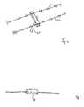
- FIG. 3illustrates a lumped inductor coupled in series with the transmission line of FIG. 2 , in accordance with one embodiment of the present invention.
- FIG. 4illustrates a clamped-on inductor coupled with the transmission line of FIG. 2 in accordance with another embodiment of the present invention.
- FIG. 1illustrates an electric distribution arrangement that is employed to carry high frequency communication signals.
- a generator station 12provides transmission voltage signals to substations 14 .
- substations 16are in turn coupled to electric poles 20 , for directing a power line 18 towards end users.
- the voltage signalis stepped down, for transmitting power to end user homes and offices.
- a backhaul network 22is coupled to an Internet network 24 from one end and to the electric distribution system on the other end.
- Backhaul network 22is coupled to a substation router 26 , which in turn is coupled to a utility line via a coupler 28 .
- backhaul network 22provides Internet communication signals to the transmission lines, and ultimately to end user's 102 electric outlets. It is noted that the invention is not limited in scope in that respect and other signals such as those generated within voice networks 90 and other types of data networks 92 can be injected into the utility lines.
- FIG. 2illustrates an electric pole 20 with a portion of the utility lines extending therefrom in accordance with one embodiment of the invention.
- each utility line 40contains a plurality of inductors 42 disposed at selected intervals along their length. Inductors 42 may be disposed at regular intervals, or may be disposed at irregular intervals depending on various requirements in each circumstance.
- inductorssubstantially eliminate the radiation emitted by the utility line 40 when carrying a high frequency HF communication signal. This follows, because the power, in general and signal power specifically, is characterized by E ⁇ I
- Eis the voltage level and I, is the current level of the signal. Therefore, by raising the voltage level and reducing the current level by a like amount, the power is preserved, but the radiation, which is proportional to the current, is reduced.
- Utility line 40has a characteristic impedance, Z 0 , which determines the ration of the voltage to current within line 40 . By raising Z 0 the current that properly feeds the lines is reduced, while the required voltage is increased.
- the characteristic impedance of a lossless transmission lineis equal to Z 0 ⁇ square root over (L/C) ⁇ Where L and C are respectively the inductance and capacitance, per unit length.
- the capacitance of the utility lineis primarily determined by the distance between the conductors. This distance is determined by the requirements for AC power distribution, and cannot be changed.
- the inductanceis one variable, which may be changed in accordance to various embodiments of the present invention.
- the inductorsare chosen so that their reactance is negligible at the power line frequency, which is typically 50–60 Hz, and significant in the high frequency (HF) band.
- the power line frequencytypically 50–60 Hz
- HFhigh frequency
- an inductance of 1 ⁇ Henryhas a reactance of well below a milliohm at 60 Hz, but at 6 MHz it has a reactance of about 38 ohms.
- the exact value of the inductorshas be selected based on the actual characteristics of the power line.
- the overall inductance L of the power linecan be derived from the equation
- FIG. 3illustrates an exemplary inductor 60 disposed along a power line 40 in accordance with one embodiment of the invention.
- Inductor 60is a ferrite bead lumped inductor, which is coupled along the power line in a clamped arrangement.
- the clamped inductorsare positioned at desired intervals along the power line.
- FIG. 4illustrates an exemplary inductor 80 disposed along power line 40 in accordance with another embodiment of the invention.
- Inductor 80is a series inserted inductor, located at desired locations along the power line.
- the radiation emitted from the transmission lines that carry high frequency communication signalsis accomplished by first determining the voltage signal level and the current signal level of the signal transmitted via the transmission line. Thereafter, the lumped inductors are added to the power line at desired intervals. These intervals may or may not be regular. Thereafter, the system increases the voltage signal level, as the current signal level is decreased in substantially the same amount, due to the addition of the inductors and the resultant increase in the overall power line inductance. As a result of the decreased current signal level, the radiation emitted from the power line also decreases.
Landscapes
- Engineering & Computer Science (AREA)
- Power Engineering (AREA)
- Computer Networks & Wireless Communication (AREA)
- Signal Processing (AREA)
- Cable Transmission Systems, Equalization Of Radio And Reduction Of Echo (AREA)
Abstract
Description
This invention relates to data communications, and more specifically to a broadband communication system employing power transmission lines.
Within the past few years a new mode of communicating data has been accomplished by employing existing power cable or transmission lines. This mode of communications is referred to as broadband over power lines (BOPL). BOPL allows power utility companies to utilize their backbone electric grid infrastructure to offer their customers high speed telecommunications services. Thus, power utility companies can now provide continuous high speed Internet access by modest changes of their existing plant.
Broadband over power line technology employs building and/or overhead power lines to conduct HF and VHF digital signals for allowing computers to connect to the Internet. The FCC views this technology as a competitive Internet access point, and the utilities view the technology as a means to use existing infrastructure to generate additional revenue from something other than power generation and distribution.
One important concern about transmission of high frequency signals over power lines is electromagnetic radiation from the power lines into already used frequency channels. More specifically, for high frequency signals, the power line may act as an antenna that is able to emanate electromagnetic radiation leading to a significant interference to over-the-air radio services.
Under current FCC regulations, power transmission lines may emit signals having a power of up to 30 microvolts/meter at a distance of 30 meters from the source. However, such emission levels can easily interfere with other overlapping frequency channels, such as those used by Amateur Radio Service. The problem with such interference is that it affects not only the Amateur Radio community, but also those who employ radio services using High Frequency HF spectrum.
Thus, there is a need for an arrangement that can effectively overcome the problems arising from transmission of high frequency signals over power lines.
In accordance with one embodiment of the invention high frequency signals are carried over an electric utility power line. The high frequency signal maintains a constant signal power necessary for a satisfactory demodulation. The high frequency current signal, however, is reduced so as to reduce the radio frequency radiation emitted from the utility power line.
In accordance with another embodiment of the invention, a plurality of inductive loads are installed at selected locations along the utility power line. In accordance with another embodiment of the invention, the inductive loads are clamp-on inductors. In accordance with another embodiment of the invention, the inductive loads are connected in series with the utility line.
The inductors are chosen so that their reactance is negligible at the power line frequency, which is about 50 or 60 Hz, and their reactance is significant at High Frequency (HF) band.
In order for the power line to maintain the same signal power with the inductive loads as a power line without the inductive loads, the value of the voltage level of the transmitted signal is increased, while the value of the current level of the transmitted signal is decreased. Since the radiation is caused by current I, a reduction in current level leads to a reduction in emitted radiation.
Thus, the inductors raise the impedance of the power lines, thereby allowing the transfer of power to the lines at a higher voltage and a lower current, than what is required if the inductors were not employed.
Abackhaul network 22 is coupled to an Internet network24 from one end and to the electric distribution system on the other end.Backhaul network 22 is coupled to asubstation router 26, which in turn is coupled to a utility line via a coupler28. As such,backhaul network 22 provides Internet communication signals to the transmission lines, and ultimately to end user's102 electric outlets. It is noted that the invention is not limited in scope in that respect and other signals such as those generated within voice networks90 and other types of data networks92 can be injected into the utility lines.
The use of inductors substantially eliminate the radiation emitted by the utility line40 when carrying a high frequency HF communication signal. This follows, because the power, in general and signal power specifically, is characterized by
E×I
E×I
Wherein E is the voltage level and I, is the current level of the signal. Therefore, by raising the voltage level and reducing the current level by a like amount, the power is preserved, but the radiation, which is proportional to the current, is reduced.
Utility line40 has a characteristic impedance, Z0, which determines the ration of the voltage to current within line40. By raising Z0the current that properly feeds the lines is reduced, while the required voltage is increased.
The characteristic impedance of a lossless transmission line is equal to
Z0√{square root over (L/C)}
Where L and C are respectively the inductance and capacitance, per unit length. The capacitance of the utility line is primarily determined by the distance between the conductors. This distance is determined by the requirements for AC power distribution, and cannot be changed. Thus, the inductance is one variable, which may be changed in accordance to various embodiments of the present invention.
Since it is desired to increase the impedance Z0, it is necessary to increase the inductance per unit length. This is accomplished by installing at regular or irregular distances lumped inductances on the power line.
In accordance with one embodiment of the invention, the inductors are chosen so that their reactance is negligible at the power line frequency, which is typically 50–60 Hz, and significant in the high frequency (HF) band. For example, an inductance of 1 μHenry has a reactance of well below a milliohm at 60 Hz, but at 6 MHz it has a reactance of about 38 ohms.
In accordance with various embodiments of the invention, the exact value of the inductors has be selected based on the actual characteristics of the power line. For example the overall inductance L of the power line can be derived from the equation
where μ is permiability, D is the space between the two wires, a is the radius of the conductors and d is the unit length. As such the intrinsic inductance per unit length may be calculated. From this information and the length of the power line, the tolerable increase in overall inductance L may be calculated based on an acceptable voltage drop of the AC utility power delivery. Furthermore, the economies of the placement of the lumped inductors may be determined, such that the overall desired increase in impedance L is balanced against the cost and effect on AC power convergence.
Thus, in accordance to various embodiments of the invention, it is possible to reduce the radiation emitted from the transmission lines that carry high frequency communication signals. This is accomplished by first determining the voltage signal level and the current signal level of the signal transmitted via the transmission line. Thereafter, the lumped inductors are added to the power line at desired intervals. These intervals may or may not be regular. Thereafter, the system increases the voltage signal level, as the current signal level is decreased in substantially the same amount, due to the addition of the inductors and the resultant increase in the overall power line inductance. As a result of the decreased current signal level, the radiation emitted from the power line also decreases.
Claims (12)
1. A method for decreasing high frequency (HF) radiation emission from a power line spanning a plurality of utility poles or towers, said method comprising the steps of:
transmitting a utility power signal over said power line;
transmitting a high frequency communication signal over said power line so as to provide a combined utility and high frequency signal over said power line; and
providing a plurality of inductors disposed along a span of said power line, between each of said poles or towers, such that said high frequency radiation emission from said power line generated by said high frequency communication signal is reduced along said span of said power line where said inductors are maintained.
2. The method in accordance withclaim 1 further comprising the step of increasing a voltage level of said combined signal corresponding to an increased impedance in said power line as a result of said step of providing a plurality of inductors.
3. The method in accordance withclaim 2 , wherein said step of providing a plurality of inductors further comprises the step of providing said plurality of inductors at regular intervals.
4. The method in accordance withclaim 2 , wherein said step of providing a plurality of inductors further comprises the step of providing said plurality of inductors at irregular intervals.
5. The method in accordance withclaim 2 , wherein said step of providing a plurality of inductors further comprises the step of providing a plurality of clamped inductors.
6. The method in accordance withclaim 2 , wherein said step of providing a plurality of inductors further comprises the step of providing a plurality of series inserted inductors.
7. A system for decreasing high frequency (HF) radiation emission from a power line spanning a plurality of utility poles or towers, comprising:
a first transmitter configured to transmit a utility power signal over said power line;
a second transmitter configured to transmit a high frequency communication signal over said power line so as to provide a combined utility and high frequency signal over said power line; and
a plurality of inductors disposed along said power line , between each of said poles or towers, such that said high frequency radiation emission from said power line generated by said high frequency communication signal is reduced along said span of said power line where said inductors are maintained.
8. The system in accordance withclaim 7 further comprising means for increasing a voltage level of said combined signal corresponding to an increased impedance in said power line as a result of said plurality of inductors.
9. The system in accordance withclaim 7 , wherein said plurality of inductors are located at regular intervals.
10. The system in accordance withclaim 7 , said plurality of inductors are located at irregular intervals.
11. The system in accordance withclaim 7 , wherein at least one of said inductors is a clamped inductor.
12. The system in accordance withclaim 7 , wherein at least one of said plurality of inductors is a series inserted inductor.
Priority Applications (1)
| Application Number | Priority Date | Filing Date | Title |
|---|---|---|---|
| US10/763,054US7079012B2 (en) | 2004-01-21 | 2004-01-21 | System and method for distributing broadband communication signals over power lines |
Applications Claiming Priority (1)
| Application Number | Priority Date | Filing Date | Title |
|---|---|---|---|
| US10/763,054US7079012B2 (en) | 2004-01-21 | 2004-01-21 | System and method for distributing broadband communication signals over power lines |
Publications (2)
| Publication Number | Publication Date |
|---|---|
| US20050157442A1 US20050157442A1 (en) | 2005-07-21 |
| US7079012B2true US7079012B2 (en) | 2006-07-18 |
Family
ID=34750396
Family Applications (1)
| Application Number | Title | Priority Date | Filing Date |
|---|---|---|---|
| US10/763,054Expired - LifetimeUS7079012B2 (en) | 2004-01-21 | 2004-01-21 | System and method for distributing broadband communication signals over power lines |
Country Status (1)
| Country | Link |
|---|---|
| US (1) | US7079012B2 (en) |
Cited By (12)
| Publication number | Priority date | Publication date | Assignee | Title |
|---|---|---|---|---|
| US20090109981A1 (en)* | 2007-10-25 | 2009-04-30 | Michael Keselman | Out-of-band management for broadband over powerline network |
| US20090125255A1 (en)* | 2007-11-08 | 2009-05-14 | Michael Keselman | Methods and apparatus for measuring voltage and voltage phase angle on bpl line |
| US20090124209A1 (en)* | 2007-11-08 | 2009-05-14 | Michael Keselman | Methods and system for configuration of broadband over power lines |
| US20090153133A1 (en)* | 2007-12-13 | 2009-06-18 | Michael Keselman | Methods and apparatus for collecting characteristics of a power line a bpl system |
| US7715534B2 (en) | 2000-03-20 | 2010-05-11 | Mosaid Technologies Incorporated | Telephone outlet for implementing a local area network over telephone lines and a local area network using such outlets |
| US7852874B2 (en) | 1998-07-28 | 2010-12-14 | Mosaid Technologies Incorporated | Local area network of serial intelligent cells |
| US7873058B2 (en) | 2004-11-08 | 2011-01-18 | Mosaid Technologies Incorporated | Outlet with analog signal adapter, a method for use thereof and a network using said outlet |
| US7876767B2 (en) | 2000-04-19 | 2011-01-25 | Mosaid Technologies Incorporated | Network combining wired and non-wired segments |
| US7881462B2 (en) | 2004-02-16 | 2011-02-01 | Mosaid Technologies Incorporated | Outlet add-on module |
| US7990908B2 (en) | 2002-11-13 | 2011-08-02 | Mosaid Technologies Incorporated | Addressable outlet, and a network using the same |
| US9627003B2 (en) | 2014-05-19 | 2017-04-18 | Trinity Solutions Llc | Explosion proof underground mining recording system and method of using same |
| US10001008B2 (en) | 2012-11-20 | 2018-06-19 | Trinity Solutions | System and method for providing broadband communications over power cabling |
Families Citing this family (1)
| Publication number | Priority date | Publication date | Assignee | Title |
|---|---|---|---|---|
| ES2402508B1 (en)* | 2011-09-29 | 2014-03-11 | Instituto Tecnológico De La Energía-Ite | LARGE BAND WIDTH COUPLING DEVICE FOR POWER LINES |
Citations (41)
| Publication number | Priority date | Publication date | Assignee | Title |
|---|---|---|---|---|
| US3946279A (en)* | 1974-12-10 | 1976-03-23 | The United States Of America As Represented By The Secretary Of The Interior | Active impedance multiplier |
| US3974404A (en) | 1973-02-15 | 1976-08-10 | Motorola, Inc. | Integrated circuit interface stage for high noise environment |
| US4021797A (en) | 1974-11-28 | 1977-05-03 | Siemens Aktiengesellschaft | Audio frequency power line control system |
| US4130861A (en)* | 1976-12-22 | 1978-12-19 | General Electric Company | Power line carrier noise elimination |
| US4302750A (en)* | 1979-08-03 | 1981-11-24 | Compuguard Corporation | Distribution automation system |
| US4510611A (en) | 1982-11-19 | 1985-04-09 | General Electric Company | Transceiver circuit for interfacing between a power line communication system and a data processor |
| US4635296A (en)* | 1985-02-22 | 1987-01-06 | Transkinetic Systems, Inc. | Wide bandwidth ultra high stability FM telemetry transmitter |
| US5210518A (en)* | 1991-05-10 | 1993-05-11 | Echelon Corporation | Apparatus and method for reducing errors in data caused by noise |
| US5349666A (en) | 1991-02-21 | 1994-09-20 | Mitsubishi Denki Kabushiki Kaisha | Reduced power line fluctuation/noise circuit by increasing impedance level when number of bus lines simultaneously change state exceeds the predetermined number |
| US5485040A (en) | 1991-05-10 | 1996-01-16 | Echelon Corporation | Powerline coupling network |
| US5694108A (en)* | 1996-05-01 | 1997-12-02 | Abb Power T&D Company Inc. | Apparatus and methods for power network coupling |
| US5818127A (en) | 1989-04-28 | 1998-10-06 | Videocom, Inc. | Transmission of FM video signals over various lines |
| US5929749A (en) | 1997-11-13 | 1999-07-27 | Slonim; Michael | System for improved communication and control over power lines |
| US5970138A (en) | 1995-12-04 | 1999-10-19 | Fujitsu Limited | Terminal equipment for telecommunications and information processing |
| US5977650A (en) | 1998-03-17 | 1999-11-02 | Northern Telecom Limited | Transmitting communications signals over a power line network |
| US6037678A (en) | 1997-10-03 | 2000-03-14 | Northern Telecom Limited | Coupling communications signals to a power line |
| US6144290A (en) | 1997-03-11 | 2000-11-07 | Electricite De France, Service National | Control device for the emission of carrier currents on a low voltage network |
| US6313738B1 (en)* | 1997-06-09 | 2001-11-06 | At&T Corp. | Adaptive noise cancellation system |
| US20020024423A1 (en) | 2000-03-15 | 2002-02-28 | Kline Paul A. | System and method for communication via power lines using ultra-short pulses |
| US6396392B1 (en)* | 2000-05-23 | 2002-05-28 | Wire21, Inc. | High frequency network communications over various lines |
| US6407987B1 (en) | 1989-04-28 | 2002-06-18 | Wire21, Inc. | Transformer coupler for communication over various lines |
| US20020109585A1 (en) | 2001-02-15 | 2002-08-15 | Sanderson Lelon Wayne | Apparatus, method and system for range extension of a data communication signal on a high voltage cable |
| US6441723B1 (en) | 1999-11-15 | 2002-08-27 | General Electric Company | Highly reliable power line communications system |
| US6504402B2 (en) | 1992-04-14 | 2003-01-07 | Hitachi, Ltd. | Semiconductor integrated circuit device having power reduction mechanism |
| US20030006881A1 (en) | 2000-04-12 | 2003-01-09 | Reyes Ronald R. | System and method for power line communication |
| US6515485B1 (en) | 2000-04-19 | 2003-02-04 | Phonex Broadband Corporation | Method and system for power line impedance detection and automatic impedance matching |
| US6522626B1 (en) | 1998-12-15 | 2003-02-18 | Nortel Networks Limited | Power line communications system and method of operation thereof |
| US20030039317A1 (en) | 2001-08-21 | 2003-02-27 | Taylor Douglas Hamilton | Method and apparatus for constructing a sub-carrier map |
| US6549120B1 (en) | 2000-11-24 | 2003-04-15 | Kinectrics Inc. | Device for sending and receiving data through power distribution transformers |
| US20030071721A1 (en) | 2001-08-04 | 2003-04-17 | Manis Constantine N. | Adaptive radiated emission control |
| US20030071719A1 (en) | 2001-10-02 | 2003-04-17 | Crenshaw Ralph E. | Method and apparatus for attaching power line communications to customer premises |
| US6559757B1 (en)* | 2000-10-26 | 2003-05-06 | Home Tough Lighting Systems Llc | Data communication over power lines |
| US20030095036A1 (en) | 2001-11-19 | 2003-05-22 | Tdk Corporation | Power line communication system and power line branching apparatus |
| US20030133473A1 (en) | 2001-08-04 | 2003-07-17 | Manis Constantine N. | Power line communication system |
| US20030137405A1 (en) | 2002-01-24 | 2003-07-24 | Takashi Kaku | Communication scheme suppressing leakage electromagnetic fields |
| US20030156012A1 (en) | 2001-12-21 | 2003-08-21 | Omidi Mohammad Javad | Apparatus and method for a low-rate data transmission mode over a power line |
| US20030156014A1 (en) | 2002-01-24 | 2003-08-21 | Matsushita Electric Industrial Co., Ltd. | Power-line carrier communication apparatus |
| US20030160684A1 (en) | 1999-12-30 | 2003-08-28 | Ambient Corporation | Inductive coupling of a data signal for a power transmission cable |
| US20030179080A1 (en) | 2001-12-21 | 2003-09-25 | Mollenkopf James Douglas | Facilitating communication of data signals on electric power systems |
| US20030190110A1 (en) | 2001-02-14 | 2003-10-09 | Kline Paul A. | Method and apparatus for providing inductive coupling and decoupling of high-frequency, high-bandwidth data signals directly on and off of a high voltage power line |
| US6686832B2 (en)* | 2000-05-23 | 2004-02-03 | Satius, Inc. | High frequency network multiplexed communications over various lines |
Family Cites Families (14)
| Publication number | Priority date | Publication date | Assignee | Title |
|---|---|---|---|---|
| US137405A (en)* | 1873-04-01 | Improvement in curtain-fixtures | ||
| US71721A (en)* | 1867-12-03 | Improvement in locking-knob latches | ||
| US179080A (en)* | 1876-06-20 | Improvement in carpet-stretchers | ||
| US156014A (en)* | 1874-10-20 | Improvement in soft-metal hammers | ||
| US95036A (en)* | 1869-09-21 | Jean ma ie | ||
| US160684A (en)* | 1875-03-09 | Improvement in knit fabrics | ||
| US109585A (en)* | 1870-11-29 | Improvement in hemmers and fellers for sewing-machines | ||
| US156012A (en)* | 1874-10-20 | Improvement in can-seaming machines | ||
| US24423A (en)* | 1859-06-14 | Grain-hulling machine | ||
| US6881A (en)* | 1849-11-20 | Improvement in distilling and rectifying spirits | ||
| US133473A (en)* | 1872-11-26 | Improvement in binders attachments for harvesters | ||
| US39317A (en)* | 1863-07-21 | Improvement in machines for grinding and polishing cutlery | ||
| US71719A (en)* | 1867-12-03 | Joseph douglass | ||
| US190110A (en)* | 1877-04-24 | Improvement in check-rowers and droppers |
- 2004
- 2004-01-21USUS10/763,054patent/US7079012B2/ennot_activeExpired - Lifetime
Patent Citations (42)
| Publication number | Priority date | Publication date | Assignee | Title |
|---|---|---|---|---|
| US3974404A (en) | 1973-02-15 | 1976-08-10 | Motorola, Inc. | Integrated circuit interface stage for high noise environment |
| US4021797A (en) | 1974-11-28 | 1977-05-03 | Siemens Aktiengesellschaft | Audio frequency power line control system |
| US3946279A (en)* | 1974-12-10 | 1976-03-23 | The United States Of America As Represented By The Secretary Of The Interior | Active impedance multiplier |
| US4130861A (en)* | 1976-12-22 | 1978-12-19 | General Electric Company | Power line carrier noise elimination |
| US4302750A (en)* | 1979-08-03 | 1981-11-24 | Compuguard Corporation | Distribution automation system |
| US4510611A (en) | 1982-11-19 | 1985-04-09 | General Electric Company | Transceiver circuit for interfacing between a power line communication system and a data processor |
| US4635296A (en)* | 1985-02-22 | 1987-01-06 | Transkinetic Systems, Inc. | Wide bandwidth ultra high stability FM telemetry transmitter |
| US6407987B1 (en) | 1989-04-28 | 2002-06-18 | Wire21, Inc. | Transformer coupler for communication over various lines |
| US5818127A (en) | 1989-04-28 | 1998-10-06 | Videocom, Inc. | Transmission of FM video signals over various lines |
| US5349666A (en) | 1991-02-21 | 1994-09-20 | Mitsubishi Denki Kabushiki Kaisha | Reduced power line fluctuation/noise circuit by increasing impedance level when number of bus lines simultaneously change state exceeds the predetermined number |
| US5210518A (en)* | 1991-05-10 | 1993-05-11 | Echelon Corporation | Apparatus and method for reducing errors in data caused by noise |
| US5485040A (en) | 1991-05-10 | 1996-01-16 | Echelon Corporation | Powerline coupling network |
| US6504402B2 (en) | 1992-04-14 | 2003-01-07 | Hitachi, Ltd. | Semiconductor integrated circuit device having power reduction mechanism |
| US5970138A (en) | 1995-12-04 | 1999-10-19 | Fujitsu Limited | Terminal equipment for telecommunications and information processing |
| US5694108A (en)* | 1996-05-01 | 1997-12-02 | Abb Power T&D Company Inc. | Apparatus and methods for power network coupling |
| US6144290A (en) | 1997-03-11 | 2000-11-07 | Electricite De France, Service National | Control device for the emission of carrier currents on a low voltage network |
| US6313738B1 (en)* | 1997-06-09 | 2001-11-06 | At&T Corp. | Adaptive noise cancellation system |
| US6037678A (en) | 1997-10-03 | 2000-03-14 | Northern Telecom Limited | Coupling communications signals to a power line |
| US5929749A (en) | 1997-11-13 | 1999-07-27 | Slonim; Michael | System for improved communication and control over power lines |
| US5977650A (en) | 1998-03-17 | 1999-11-02 | Northern Telecom Limited | Transmitting communications signals over a power line network |
| US6522626B1 (en) | 1998-12-15 | 2003-02-18 | Nortel Networks Limited | Power line communications system and method of operation thereof |
| US6441723B1 (en) | 1999-11-15 | 2002-08-27 | General Electric Company | Highly reliable power line communications system |
| US20030160684A1 (en) | 1999-12-30 | 2003-08-28 | Ambient Corporation | Inductive coupling of a data signal for a power transmission cable |
| US6496104B2 (en) | 2000-03-15 | 2002-12-17 | Current Technologies, L.L.C. | System and method for communication via power lines using ultra-short pulses |
| US20020024423A1 (en) | 2000-03-15 | 2002-02-28 | Kline Paul A. | System and method for communication via power lines using ultra-short pulses |
| US20030006881A1 (en) | 2000-04-12 | 2003-01-09 | Reyes Ronald R. | System and method for power line communication |
| US6515485B1 (en) | 2000-04-19 | 2003-02-04 | Phonex Broadband Corporation | Method and system for power line impedance detection and automatic impedance matching |
| US6396392B1 (en)* | 2000-05-23 | 2002-05-28 | Wire21, Inc. | High frequency network communications over various lines |
| US6686832B2 (en)* | 2000-05-23 | 2004-02-03 | Satius, Inc. | High frequency network multiplexed communications over various lines |
| US6559757B1 (en)* | 2000-10-26 | 2003-05-06 | Home Tough Lighting Systems Llc | Data communication over power lines |
| US6549120B1 (en) | 2000-11-24 | 2003-04-15 | Kinectrics Inc. | Device for sending and receiving data through power distribution transformers |
| US20030190110A1 (en) | 2001-02-14 | 2003-10-09 | Kline Paul A. | Method and apparatus for providing inductive coupling and decoupling of high-frequency, high-bandwidth data signals directly on and off of a high voltage power line |
| US20020109585A1 (en) | 2001-02-15 | 2002-08-15 | Sanderson Lelon Wayne | Apparatus, method and system for range extension of a data communication signal on a high voltage cable |
| US20030133473A1 (en) | 2001-08-04 | 2003-07-17 | Manis Constantine N. | Power line communication system |
| US20030071721A1 (en) | 2001-08-04 | 2003-04-17 | Manis Constantine N. | Adaptive radiated emission control |
| US20030039317A1 (en) | 2001-08-21 | 2003-02-27 | Taylor Douglas Hamilton | Method and apparatus for constructing a sub-carrier map |
| US20030071719A1 (en) | 2001-10-02 | 2003-04-17 | Crenshaw Ralph E. | Method and apparatus for attaching power line communications to customer premises |
| US20030095036A1 (en) | 2001-11-19 | 2003-05-22 | Tdk Corporation | Power line communication system and power line branching apparatus |
| US20030156012A1 (en) | 2001-12-21 | 2003-08-21 | Omidi Mohammad Javad | Apparatus and method for a low-rate data transmission mode over a power line |
| US20030179080A1 (en) | 2001-12-21 | 2003-09-25 | Mollenkopf James Douglas | Facilitating communication of data signals on electric power systems |
| US20030137405A1 (en) | 2002-01-24 | 2003-07-24 | Takashi Kaku | Communication scheme suppressing leakage electromagnetic fields |
| US20030156014A1 (en) | 2002-01-24 | 2003-08-21 | Matsushita Electric Industrial Co., Ltd. | Power-line carrier communication apparatus |
Cited By (25)
| Publication number | Priority date | Publication date | Assignee | Title |
|---|---|---|---|---|
| US7978726B2 (en) | 1998-07-28 | 2011-07-12 | Mosaid Technologies Incorporated | Local area network of serial intelligent cells |
| US8908673B2 (en) | 1998-07-28 | 2014-12-09 | Conversant Intellectual Property Management Incorporated | Local area network of serial intelligent cells |
| US8885660B2 (en) | 1998-07-28 | 2014-11-11 | Conversant Intellectual Property Management Incorporated | Local area network of serial intelligent cells |
| US8885659B2 (en) | 1998-07-28 | 2014-11-11 | Conversant Intellectual Property Management Incorporated | Local area network of serial intelligent cells |
| US7852874B2 (en) | 1998-07-28 | 2010-12-14 | Mosaid Technologies Incorporated | Local area network of serial intelligent cells |
| US8867523B2 (en) | 1998-07-28 | 2014-10-21 | Conversant Intellectual Property Management Incorporated | Local area network of serial intelligent cells |
| US7715534B2 (en) | 2000-03-20 | 2010-05-11 | Mosaid Technologies Incorporated | Telephone outlet for implementing a local area network over telephone lines and a local area network using such outlets |
| US8855277B2 (en) | 2000-03-20 | 2014-10-07 | Conversant Intellectual Property Managment Incorporated | Telephone outlet for implementing a local area network over telephone lines and a local area network using such outlets |
| US8363797B2 (en) | 2000-03-20 | 2013-01-29 | Mosaid Technologies Incorporated | Telephone outlet for implementing a local area network over telephone lines and a local area network using such outlets |
| US8848725B2 (en) | 2000-04-19 | 2014-09-30 | Conversant Intellectual Property Management Incorporated | Network combining wired and non-wired segments |
| US8873586B2 (en) | 2000-04-19 | 2014-10-28 | Conversant Intellectual Property Management Incorporated | Network combining wired and non-wired segments |
| US8982904B2 (en) | 2000-04-19 | 2015-03-17 | Conversant Intellectual Property Management Inc. | Network combining wired and non-wired segments |
| US8982903B2 (en) | 2000-04-19 | 2015-03-17 | Conversant Intellectual Property Management Inc. | Network combining wired and non-wired segments |
| US7876767B2 (en) | 2000-04-19 | 2011-01-25 | Mosaid Technologies Incorporated | Network combining wired and non-wired segments |
| US8873575B2 (en) | 2000-04-19 | 2014-10-28 | Conversant Intellectual Property Management Incorporated | Network combining wired and non-wired segments |
| US8867506B2 (en) | 2000-04-19 | 2014-10-21 | Conversant Intellectual Property Management Incorporated | Network combining wired and non-wired segments |
| US7990908B2 (en) | 2002-11-13 | 2011-08-02 | Mosaid Technologies Incorporated | Addressable outlet, and a network using the same |
| US7881462B2 (en) | 2004-02-16 | 2011-02-01 | Mosaid Technologies Incorporated | Outlet add-on module |
| US7873058B2 (en) | 2004-11-08 | 2011-01-18 | Mosaid Technologies Incorporated | Outlet with analog signal adapter, a method for use thereof and a network using said outlet |
| US20090109981A1 (en)* | 2007-10-25 | 2009-04-30 | Michael Keselman | Out-of-band management for broadband over powerline network |
| US20090124209A1 (en)* | 2007-11-08 | 2009-05-14 | Michael Keselman | Methods and system for configuration of broadband over power lines |
| US20090125255A1 (en)* | 2007-11-08 | 2009-05-14 | Michael Keselman | Methods and apparatus for measuring voltage and voltage phase angle on bpl line |
| US20090153133A1 (en)* | 2007-12-13 | 2009-06-18 | Michael Keselman | Methods and apparatus for collecting characteristics of a power line a bpl system |
| US10001008B2 (en) | 2012-11-20 | 2018-06-19 | Trinity Solutions | System and method for providing broadband communications over power cabling |
| US9627003B2 (en) | 2014-05-19 | 2017-04-18 | Trinity Solutions Llc | Explosion proof underground mining recording system and method of using same |
Also Published As
| Publication number | Publication date |
|---|---|
| US20050157442A1 (en) | 2005-07-21 |
Similar Documents
| Publication | Publication Date | Title |
|---|---|---|
| US7218219B2 (en) | Data communication over a power line | |
| US7079012B2 (en) | System and method for distributing broadband communication signals over power lines | |
| Gebhardt et al. | Physical and regulatory constraints for communication over the power supply grid | |
| US9667320B2 (en) | Power line communication modem, power line communication system, power line communication method | |
| US7026917B2 (en) | Power line communication system and method of operating the same | |
| US6037678A (en) | Coupling communications signals to a power line | |
| US7098773B2 (en) | Power line communication system and method of operating the same | |
| EP1776618B1 (en) | Method and system for radio-frequency signal coupling to medium tension power lines with auto-tuning device | |
| EA006177B1 (en) | Inductive coupling of a data signal to a power transmission cable | |
| CZ56097A3 (en) | Distribution network | |
| JP2004297107A (en) | Power line carrier device | |
| CZ305996A3 (en) | Method of transmitting telecommunication signals and a telecommunication network for making the same | |
| US8149106B2 (en) | Apparatus and method for data communication over power lines | |
| US7088232B2 (en) | System and method for reducing radiation when distributing broadband communication signals over power lines | |
| AU2005299526B2 (en) | Arrangement of inductive couplers for data communication | |
| US7627402B2 (en) | Device and method for designing power line communication system networks | |
| US20090124209A1 (en) | Methods and system for configuration of broadband over power lines | |
| Karduri et al. | Near-field coupling between broadband over power line (BPL) and high-frequency communication systems | |
| Louie et al. | Discussion on power line carrier applications | |
| WO2001041325A2 (en) | Telecommunication system | |
| Podszeck | Properties of Power Lines in the Carrier Frequency Range | |
| JPH0666716B2 (en) | Transmission and distribution line information transmission method | |
| Brannon | The radio spectrum requirements of broadband power line telecommunications systems | |
| HK1108032A (en) | Method and system for radio-frequency signal coupling to medium tension power lines with auto-tuning device |
Legal Events
| Date | Code | Title | Description |
|---|---|---|---|
| STCF | Information on status: patent grant | Free format text:PATENTED CASE | |
| AS | Assignment | Owner name:FOX ENTERTAINMENT GROUP, NEW YORK Free format text:ASSIGNMENT OF ASSIGNORS INTEREST;ASSIGNOR:WETMORE, EVANS;REEL/FRAME:020325/0437 Effective date:20071220 | |
| FPAY | Fee payment | Year of fee payment:4 | |
| FPAY | Fee payment | Year of fee payment:8 | |
| MAFP | Maintenance fee payment | Free format text:PAYMENT OF MAINTENANCE FEE, 12TH YEAR, LARGE ENTITY (ORIGINAL EVENT CODE: M1553) Year of fee payment:12 |