US7078832B2 - Linear motor, and linear compressor using the same - Google Patents
Linear motor, and linear compressor using the sameDownload PDFInfo
- Publication number
- US7078832B2 US7078832B2US10/493,495US49349504AUS7078832B2US 7078832 B2US7078832 B2US 7078832B2US 49349504 AUS49349504 AUS 49349504AUS 7078832 B2US7078832 B2US 7078832B2
- Authority
- US
- United States
- Prior art keywords
- mover
- linear motor
- stator
- motor according
- elastic member
- Prior art date
- Legal status (The legal status is an assumption and is not a legal conclusion. Google has not performed a legal analysis and makes no representation as to the accuracy of the status listed.)
- Expired - Fee Related
Links
Images


Classifications
- H—ELECTRICITY
- H02—GENERATION; CONVERSION OR DISTRIBUTION OF ELECTRIC POWER
- H02K—DYNAMO-ELECTRIC MACHINES
- H02K33/00—Motors with reciprocating, oscillating or vibrating magnet, armature or coil system
- H02K33/02—Motors with reciprocating, oscillating or vibrating magnet, armature or coil system with armatures moved one way by energisation of a single coil system and returned by mechanical force, e.g. by springs
- F—MECHANICAL ENGINEERING; LIGHTING; HEATING; WEAPONS; BLASTING
- F04—POSITIVE - DISPLACEMENT MACHINES FOR LIQUIDS; PUMPS FOR LIQUIDS OR ELASTIC FLUIDS
- F04B—POSITIVE-DISPLACEMENT MACHINES FOR LIQUIDS; PUMPS
- F04B35/00—Piston pumps specially adapted for elastic fluids and characterised by the driving means to their working members, or by combination with, or adaptation to, specific driving engines or motors, not otherwise provided for
- F04B35/04—Piston pumps specially adapted for elastic fluids and characterised by the driving means to their working members, or by combination with, or adaptation to, specific driving engines or motors, not otherwise provided for the means being electric
- F04B35/045—Piston pumps specially adapted for elastic fluids and characterised by the driving means to their working members, or by combination with, or adaptation to, specific driving engines or motors, not otherwise provided for the means being electric using solenoids
- H—ELECTRICITY
- H02—GENERATION; CONVERSION OR DISTRIBUTION OF ELECTRIC POWER
- H02K—DYNAMO-ELECTRIC MACHINES
- H02K33/00—Motors with reciprocating, oscillating or vibrating magnet, armature or coil system
- H02K33/16—Motors with reciprocating, oscillating or vibrating magnet, armature or coil system with polarised armatures moving in alternate directions by reversal or energisation of a single coil system
- H—ELECTRICITY
- H02—GENERATION; CONVERSION OR DISTRIBUTION OF ELECTRIC POWER
- H02K—DYNAMO-ELECTRIC MACHINES
- H02K41/00—Propulsion systems in which a rigid body is moved along a path due to dynamo-electric interaction between the body and a magnetic field travelling along the path
- H02K41/02—Linear motors; Sectional motors
- H—ELECTRICITY
- H02—GENERATION; CONVERSION OR DISTRIBUTION OF ELECTRIC POWER
- H02K—DYNAMO-ELECTRIC MACHINES
- H02K7/00—Arrangements for handling mechanical energy structurally associated with dynamo-electric machines, e.g. structural association with mechanical driving motors or auxiliary dynamo-electric machines
- H02K7/14—Structural association with mechanical loads, e.g. with hand-held machine tools or fans
- Y—GENERAL TAGGING OF NEW TECHNOLOGICAL DEVELOPMENTS; GENERAL TAGGING OF CROSS-SECTIONAL TECHNOLOGIES SPANNING OVER SEVERAL SECTIONS OF THE IPC; TECHNICAL SUBJECTS COVERED BY FORMER USPC CROSS-REFERENCE ART COLLECTIONS [XRACs] AND DIGESTS
- Y10—TECHNICAL SUBJECTS COVERED BY FORMER USPC
- Y10S—TECHNICAL SUBJECTS COVERED BY FORMER USPC CROSS-REFERENCE ART COLLECTIONS [XRACs] AND DIGESTS
- Y10S92/00—Expansible chamber devices
- Y10S92/02—Fluid bearing
Definitions
- the present inventionrelates to a linear motor and a linear compressor using the linear motor and used in a refrigerating cycle or the like.
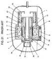
- FIG. 21is a sectional view of the conventional linear compressor.
- a closed casing (as will be called the “case”) 1houses a body 3 having a linear motor 2 and holds lubricating oil 4 .
- the linear motor 2is constructed of a stator 9 and a mover 12 .
- the stator 9is composed of a first silicon steel sheet layer (as will be called the “steel sheet layer”) 6 having a hollow cylinder shape, and a second silicon steel sheet layer (as will be called the “steel sheet layer”) 8 of a hollow cylinder shape provided with a coil 7 and formed at a predetermined clearance on the outer circumference of the steel sheet layer 6 . Both the steel sheet layers 6 and 8 are held in a frame 5 .
- the mover 12is loosely inserted between the steel sheet layer 6 and the steel sheet layer 8 and is formed into a hollow cylinder shape by adhering a plurality of magnets 11 to the distal end portion of a magnet shell 10 made of a non-magnetic material.
- the magnets 11are generally made of a magnet material of a rare earth element having a ferromagnetic field such as neodymium, and are magnetized in a direction perpendicular to the rocking direction of the mover 12 .
- a cylinder 14 having a cylindrical bore and a piston 15 inserted reciprocally in the cylinder 14form a bearing section 16 inbetween.
- the piston 15 and the magnet shell 10are integrally formed in a coaxial shape.
- the cylinder 14is arranged on the inner side of the steel sheet layer 6 formed in a hollow cylinder shape, and has the frame 5 formed on its outer circumference.
- the piston 15is formed into such a hollow cylinder shape as to form a suction passage (as will be called the “passage”) 17 in its internal space.
- a suction valveas will be called the “valve” 19 .
- a discharge valveas will be called the “valve” 20 is also arranged in the open end of the compression chamber 18 .
- the cylinder 14 , the piston 15 and the steel layers 6 and 8share their axes.
- the piston 15retains the mover 12 , through the bearing section 16 between itself and the cylinder 14 .
- the magnet 11holds predetermined clearances between itself and the steel sheet layer 6 and the steel sheet layer 8 , respectively.
- Both an inner resonance spring (as will be called the “spring”) 21 and an outer resonance spring (as will be called the “spring”) 22are compression coil springs.
- the spring 21is arranged to contact with the steel sheet layer 6 and the magnet shell 10
- the spring 22is arranged to contact with the magnet shell 10 and an outer frame 23 . Both the springs 21 and 22 are assembled in compressed states.
- an oil pump 24is formed in the bottom portion of the body 3 and is positioned in the lubricating oil 4 .
- the spring 21is sandwiched between the cylinder 14 and the steel sheet layer 6 and supports the inner side of the mover 12 elastically.
- the spring 22supports the outer side of the mover 12 elastically.
- the oil pump 24is caused to feed the lubricating oil to the bearing section 16 by the vibrations of the compressor body 3 .
- Such a compressoris disclosed in Japanese Patent Unexamined Publication No. 2001-73942, for example.
- the mover 12rocks between the steel sheet layer 6 and the steel sheet layer 8 . Specifically, it is necessary that the mover 12 be prevented from contacting with both the steel sheet layers 6 and 8 .
- the clearancesare individually formed between the mover 12 and the steel sheet layers 6 and 8 .
- these clearances of the two layersact as magnetic resistances to reduce the magnetic fluxes in proportion to the distances.
- the magnet 11In order to achieve the thrust needed for driving the mover 12 , on the other hand, the magnet 11 has to be enlarged in the conventional linear motor. However, the magnet 11 employs an expensive rare earth element as its material so that the cost drastically rises as the magnet 11 becomes larger.
- the magnet shell 10 and the piston 15are connected to each other outside of the steel sheet layers 6 and 8 , and the spring 21 is arranged between the magnet shell 10 and the steel sheet layer 6 . Therefore, the magnet shell 10 has an axially long shape. In this shape, the rigidity is liable to become low especially at the distal end portion carrying the magnet 11 . For retaining the precision, therefore, it is necessary to enhance the rigidity. For this necessity, countermeasures are taken by making the sheet thicker to thereby increase the weight more.
- the magnet shell 10 of the hollow cylinder shapeis formed of a thin sheet for the lower weight, the rigidity of the magnet shell 10 or its supporting structure is insufficient.
- the imbalance of the magnetic attractionsoccurs due to the variation in the parts precision, the assembly precision or the magnetic force of the magnet 11 , and the supporting structure is deformed so that the magnet 11 is radially attracted.
- the magnet 11 and the steel sheet layers 6 and 8approach respectively in the two clearances of the two layers to thereby cause the vicious circle, in which the magnetic attractions are intensified more to make the eccentricity of the magnet 11 more.
- the magnet shell 10is subjected to a serious force so that it is deformed to generate noises.
- the steel sheet layers 6 and 8 and the magnet 11collide against each other to cause breakage.
- a linear motor of the present inventionhas: a stator including a stationary iron core and a magnet wire; a mover including a moving iron core and a magnet; and plate-shaped elastic members for supporting the mover in a manner to rock in the rocking directions.
- a linear compressor of the present inventionhas: the aforementioned linear motor; a cylinder sharing an axis in the rocking directions of the mover; and a piston inserted reciprocally in the cylinder and connected to the mover.
- FIG. 1is a sectional side elevation of a linear motor according to a first exemplary embodiment of the present invention.
- FIG. 2is a schematic diagram showing relative positions of planar springs in the linear motor of FIG. 1 .
- FIG. 3is an exploded perspective view of the linear motor of FIG. 1 .
- FIG. 4is a schematic diagram showing the action principle of the linear motor of FIG. 1 .
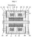
- FIG. 5is a schematic diagram showing the flow of an electric current in the linear motor of FIG. 1 .
- FIG. 6is a sectional side elevation of a linear compressor according to a second exemplary embodiment of the present invention.
- FIG. 7is a horizontal section of FIG. 6 .
- FIG. 8is a sectional side elevation of a linear compressor according to a third exemplary embodiment of the present invention.
- FIG. 9is a sectional side elevation of a linear compressor according to a fourth exemplary embodiment of the present invention.
- FIG. 10is a sectional side elevation of a linear compressor according to a fifth exemplary embodiment of the present invention.
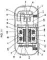
- FIG. 11is a sectional side elevation of a linear compressor according to a sixth exemplary embodiment of the present invention.
- FIG. 12is a sectional side elevation of a linear motor according to a seventh exemplary embodiment of the present invention.
- FIG. 13is a sectional view taken along line A—A of FIG. 12 .
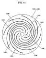
- FIG. 14is a plan view of a flexure bearing to be used in the linear motor according to the seventh exemplary embodiment of the present invention.
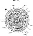
- FIG. 15is a sectional view of a linear motor according to an eighth exemplary embodiment of the present invention.
- FIG. 16is a sectional view of a linear motor according to a ninth exemplary embodiment of the present invention.
- FIG. 17is a sectional view of a linear compressor according to a tenth exemplary embodiment of the present invention.
- FIG. 18is a sectional view of an essential portion of a linear compressor according to an eleventh exemplary embodiment of the present invention.
- FIG. 19is a sectional view of an essential portion of a linear compressor according to a twelfth exemplary embodiment of the present invention.
- FIG. 20is a sectional view of a linear compressor according to a thirtieth exemplary embodiment of the present invention.
- FIG. 21is a sectional view of a conventional linear compressor.
- FIG. 1is a sectional side elevation of a linear motor according to the first exemplary embodiment of the present invention.
- FIG. 2is a schematic diagram showing the relative positions of planar springs, and perspectively shows a mover 31 , a stator 25 and a planar spring 42 B, from the side of a planar spring 42 A in FIG. 3 .
- FIG. 3is an exploded perspective view showing the assembly of the linear motor
- FIG. 4is a schematic diagram showing the action principle of the linear motor
- FIG. 5is a schematic diagram showing the directions in which the electric current of the linear motor flows.
- the stator 25 of a generally cylindrical shapeincludes two magnet wires 26 A and 26 B wound in a ring shape, a stationary iron core 27 , and a frame 28 supporting the outer circumference of the stationary iron core 27 .
- the stationary iron core 27houses the magnet wires 26 A and 26 B and forms three magnet poles 29 A, 29 B and 29 C on its inner circumference.
- the stationary iron core 27is formed by arraying silicon steel sheets (not shown), which are magnetically non-oriented and highly permeable and which are represented by a non-oriented electromagnetic steel strip of JIS C2552, for example, radially with respect to the axis of the cylinder.
- the stationary iron core 27is assembled by forming the magnet poles 29 A, 29 B and 29 C on the inner circumference and by clamping the magnet wires 26 A and 26 B wound in advance in the ring shape.
- the end portions 26 C, 26 D, 26 E and 26 F of the coils of the magnet wires 26 A and 26 Bare led out of the clearances of the radially arranged steel sheets of the stationary iron core 27 .
- the end portions 26 C, 26 D, 26 E and 26 Fare so connected that the directions for the electric currents to flow around the axis are reversed from each other in the magnet wires 26 A and 26 B.
- the end portions 26 G and 26 Hare led out of the stationary iron core 27 by making use of the electrically insulated conductors (not shown).
- the mover 31is formed into such a generally cylindrical shape as to share the axis with the stator 25 , and is housed in the stator 25 in a manner to rock in the axial directions.
- the mover 31has a moving iron core 34 and magnets 35 A and 35 B.
- the moving iron core 34is formed by integrating a shaft 32 made of a ferrous material, radially on the axis with thin sheet portions 33 , in which silicon steel sheets of a high permeability are arrayed on the outer circumference of the shaft 32 .
- the sheet portions 33are made of a silicon steel sheet, which is represented by the non-oriented electromagnetic steel strip of JIS C2552, for example.
- the magnets 35 A and 35 Bare fixed by an adhesive on the outer circumference of the moving iron core 34 through a predetermined clearance from the inner circumference of the stator 25 , and are axially separated.
- the magnets 35 A and 35 Bhave different magnet poles individually on the principal faces confronting the stationary iron core 27 .
- the magnets 35 A and 35 Bare made of magnets containing a rare earth element to have a ferromagnetic field.
- End plates 36are donut-shaped plates attached to the two end faces of the stationary iron core 27 of the stator 25 . These end plates 36 improve the strength of the silicon steel sheets arrayed radially to form the stationary iron core 27 .
- the end plates 36are made of a non-magnetic material such as stainless steel, moreover, the leakage of the magnetic fluxes from the silicon steel sheets of the stator 25 is prevented to improve the motor efficiency.
- the end plates 36are not explicitly shown in FIG. 3 .
- the planar springs 42 A and 42 Bare arranged on both axial sides of the mover 31 .
- the planar springs 42 A and 42 Bhave an elasticity and are made of a metal sheet with high flexibility, specifically, a ferrous material such as spring steel, tool steel or stainless steel, for example.
- the planar springs 42 A and 42 Bare provided with three through holes at three portions: a center portion 42 C; and distal ends 42 D and 42 E of the two helical arms.
- the center portion 42 Cis joined to the shaft 32 of the mover 31 by means of a bolt, and the distal ends 42 D and 42 D are individually joined to the frame 28 of the stator 25 by means of bolts.
- the planar springs 42 A and 42 Bconstitute an elastic member.
- the planar spring 42 Ais so attached that arm portions 42 F and 42 G leading from the center portion 42 C to the distal ends 42 D and 42 E extend counter-clockwise, as viewed from the side of the planar spring 42 A of FIG. 3 .
- the planar spring 42 Bis also attached in a similar manner. As shown in FIG. 3 , moreover, the attaching angle of the planar spring 42 A to the frame 28 is turned by about 90 degrees from the attaching angle of the planar spring 42 B to the frame 28 . As a result, the positions of the arm portions 42 F and 42 G are not aligned on the two sides of a linear motor 43 .
- the mover 31is supported in a manner to rock in the axial direction while confronting the magnet poles 29 A and 29 B of the stator 25 through a predetermined clearance.
- the mover 31 , the stator 25 and so onconstitute the linear motor 43 .
- magnetic fluxes ⁇are generated to loop to the stationary iron core 27 , the clearance, the magnet 35 A, the moving iron core 34 , the magnet 35 A, the clearance and the stationary iron core 27 , as indicated by arrows.
- Other magnetic fluxes ⁇are generated to loop to the stationary iron core 27 , the clearance, the magnet 35 B, the moving iron core 34 , the magnet 35 B, the clearance and the stationary iron core 27 .
- the magnet poles 29 A, 29 B and 29 Care magnetized to the N-pole, the S-pole and the N-pole, respectively.
- the magnets 35 A and 35 Bare fixed on the outer circumference of the moving iron core 34 , as compared with the conventional linear motor with moving magnet. Therefore, the clearances in the magnetic flux loop are reduced because of the absence of the clearance between the magnets 35 A and 35 B and the moving iron core 34 . As a result, the magnetic resistance is lowered to allow the magnetic fluxes to flow more easily than in the conventional linear motor. Therefore, the electric current to be fed to the magnet wires 26 A and 26 B for generating a predetermined magnetic flux for a necessary thrust can be reduced to improve the efficiency or to reduce the amount of magnetism.
- the mover 31can have a strong structure and can easily improve the precision of the external diameter size. Moreover, the intensity of the magnets, as might otherwise be fragile, is compensated by themselves. As a result, the magnets made of the expensive rare earth element can be thinned to lower the cost drastically, and the moving portion is lightened to improve the efficiency.
- the mover 31is supported by the planar springs 42 A and 42 B with respect to the stator 25 , and these planar springs 42 A and 42 B have a higher radial rigidity than the spring constant in the axial direction. Therefore, even if an imbalance or the like in the load of the weight of the mover 31 or in the magnetic attraction acts between the mover 31 and the stator 25 , the change in the clearance between the mover 31 and the stator 25 is remarkably small. It is, therefore, possible to prevent the mover 31 from being deformed to cause the noises and from colliding against the stator 25 .
- planar springs 42 A and 42 Bhave the relatively longer arm portions, as compared with the radius, because the arm portions 42 F and 42 G extend while turning in the same direction. Therefore, the rocking amplitude within the elastic range is so large as to relax the increase in the stresses of the springs.
- both the planar springs 42 A and 42 Bare so attached as to turn counter-clockwise, as viewed from the side of the planar spring 42 A of FIG. 3 .
- the arm portions 42 F and 42 Ghave the identical turning direction.
- the turning directions, which are caused by the fine torsion of the two springs accompanying the reciprocationare also identical. Therefore, it is possible to prevent the increase in the stress, which might otherwise be caused when the torsion is restricted by the slight turn of the mover 31 of the cylindrical shape, to thereby improve the reliability.
- planar springs 42 A and 42 Bare arranged on the two end faces of the linear motor 43 , however, the clearance between the mover 31 and the stator 25 is hidden behind the planar springs 42 A and 42 B. As a consequence, the exposed clearance is reduced, as shown in FIG. 2 .
- the planar springs 42 A and 42 Bare arranged at the attaching angles of 90 degrees on the two sides of the mover 31 .
- the clearance gaugescan be inserted all over the circumference by inserting them from the two sides of the motor. Therefore, the even clearance can be retained by connecting the mover 31 and the stator 25 through the planar springs 42 A and 42 B after the clearance gauges were inserted. As a result, the wrenching force, which might otherwise be generated due to the unbalance of the magnetic attractions, can be prevented so as to reduce the generation of the sliding loss and to prevent the wear.
- the stationary iron core 27is divided into three blocks in the axial direction across the section containing the housing portions of the magnet wires 26 A and 26 B. Therefore, the assembly can be made by inserting the magnet wires 26 A and 26 B wound in advance in the ring shape, in a clamping manner, to thereby achieve a high production efficiency.
- the stator 25has the three magnet poles, and the mover 31 has the two magnets arranged in the axial direction.
- the motorcan also be constructed even if the stator has two magnet poles or four or more magnet poles. In short, it is sufficient that the stator is provided with a plurality of magnet poles and that the mover is provided with magnets of a number less by one than the number of magnet poles of the stator.
- the flows of the magnetic fluxes in the stationary iron core 27turns their directions by about 90 degrees between the magnet poles 29 A, 29 B and 29 C and the outer circumference side of the magnet wires 26 A and 26 B.
- the stationary iron core 27is made of the non-oriented electromagnetic steel strip. So, the permeability has no orientation no matter what direction the magnetic fluxes might flow in. Therefore, no serious efficiency drop occurs.
- FIG. 6is a sectional side elevation of a linear compressor according to the second exemplary embodiment of the present invention
- FIG. 7is a horizontal section of FIG. 6
- a closed casing (as will be called the “case”) 41houses a compressor body 53 having the linear motor 43 .
- a piston 52which is connected to the mover 31 of the linear motor 43 .
- a cylinder head 54To the end face of the cylinder 51 , there are attached a cylinder head 54 and a suction muffler 55 .
- a moving unit 58is composed of the piston 52 , the mover 31 and so on.
- the piston 52is attached to the distal end of the shaft 32 of the mover 31 , and the shaft 32 and the piston 52 are rotatably connected to each other through a ball joint 61 .
- the planar springs 42 A and 42 Bare individually attached at their center portions to the moving unit 58 and at their two distal end portions to the stationary unit 57 to thereby form a resonance spring 59 .
- the cylinder 51is attached to the frame 28 of the stator 25 of the linear motor 43 , and the piston 52 is inserted in a rocking manner into the inner face 51 A of the tube-like cylinder 51 .
- the compressor body 53is so elastically supported by suspension springs 64 that the linear motor 43 may reciprocate substantially horizontally in the case 41 .
- a capillary tube 66is dipped at its one end in lubricating oil 44 contained in the bottom portion of the case 41 , and opens at its other end into a tube portion 55 A of the suction muffler 55 .
- the actions of the linear compressorthus constructed.
- the mover 31reciprocates so that the piston 52 attached thereto reciprocates in the cylinder 51 to act as the compressor.
- the frequency of the electric currentis set in the vicinity of the resonance frequency, which is determined by the mass of the stationary unit 57 and the moving unit 58 and the spring constant of the resonance spring 59 so that the linear motor 43 reciprocates efficiently with little energy loss by the resonance actions.
- the lubricating oil 44is fed from the capillary tube 66 to lubricate the sliding portions between the piston 52 and the cylinder 51 .
- the load to act between the mover 31 and the stator 25is supported by the planar springs 42 A and 42 B so that the sideway force hardly acts on the sliding portions between the piston 52 and the cylinder 51 .
- the piston 52 and the mover 31are connected through the ball joint 61 .
- the linear compressorIn the linear compressor according to this embodiment, the cylinder 51 , the planar spring 42 B, the motor 43 and the planar spring 42 A are arranged in tandem in the axial direction and in the recited order.
- the linear compressoris constructed to have the generally horizontal rocking direction of the mover 31 . Therefore, the diameter can be made smaller than that of the conventional linear compressor, in which the cylinder is arranged in the motor.
- the overall heightBy arranging that linear compressor to have a horizontal axis, the overall height can be made smaller than that of the conventional compressor. As a result, the volume of the mechanical chamber for housing the compressor is reduced when the compressor is mounted in a refrigerator, so that the capacity of the refrigerator is enlarged.
- the moving unit 58is reliably supported by the planar springs 42 A and 42 B so that its weight does not act as the contact load of the cylinder 51 and the piston 52 even if the compressor is placed in a horizontally lying position. Therefore, it is possible to prevent the drop in the efficiency, as might otherwise be caused by the increase in the sliding loss, and the drop in the reliability, as might otherwise be caused by the friction.
- FIG. 8is a sectional view of a linear compressor according to the third exemplary embodiment 3 of the present invention.
- a piston 71 and the mover 31are connected to each other through a compliance rod (as will be called the “rod”) 72 .
- the remaining constructionsare similar to those of the second embodiment.
- the rod 72is constructed of such a radially small rod-shaped elastic member as has transverse flexibility and elasticity while retaining a rigidity for supporting the load in the axial direction.
- the rod 72is made of a metallic material having an elasticity and a rigidity, such as stainless steel or spring steel. Namely, the rod 72 can move in parallel with the axis of the piston 71 and is flexible in the rotating direction. Even with a small deviation between the shaft 32 of the mover 31 and the axis of the cylinder 51 , therefore, the wrench between the piston 71 and the cylinder 51 is prevented so as to prevent the friction and the wear.
- FIG. 9is a sectional view of a linear compressor according to the fourth exemplary embodiment of the present invention.
- a cylinder 81is provided with a gas passage 81 B, which communicates with a high-pressure chamber 54 A of the cylinder head 54 at the position of an internal face 81 A confronting the piston 52 , to thereby form a gas bearing 82 .
- the lubricating oil 44 and the capillary tube 66are not provided, because the lubricating oil in not necessary.
- the remaining constructionsare similar to those of the second embodiment, as shown in FIG. 6 .
- the piston 52is held in a floating state with respect to the cylinder 81 by the high-pressure coolant gas fed from the high-pressure chamber 54 A of the cylinder head 54 .
- a gas bearinghas a remarkably low friction because it prevents the contact between the solids.
- the mover 31is supported by the planar springs 42 A and 42 B so that only a low load acts on the gas bearing 82 . This makes it sufficient to feed a small amount of gas to the gas bearing 82 .
- the ball joint 61prevents the inclinations of the piston 52 and the cylinder 81 . This reduces both the sliding loss and the leakage loss. As a result, the efficiency of the compressor is improved, and the reliability is prevented from being degraded by the friction.
- the heat transfer face of the heat exchanger of a cooling systemis not wetted with the lubricating oil so that the heat transfer with the coolant is improved to improve the efficiency of the cooling system. Accordingly as the coolant is not dissolved in the lubricating oil, the amount of the coolant to be used in the cooling system can be reduced not only to lower the cost but also to improve the efficiency of the heat exchange in the cooling system and accordingly the efficiency of the cooling system as a whole. In the case of using a natural coolant or a combustible coolant, moreover, the amount of coolant to be used can be reduced to lower the inflammability and explosiveness of the coolant, if leaked, to thereby improve the safety.
- FIG. 10is a sectional view of a linear compressor according to the fifth exemplary embodiment of the present invention.
- a cylinder 91is made of a self-lubricating material. Specifically, a diamond-like carbon film is applied to the sliding face. In this embodiment, the gas bearing 82 is not provided. The remaining constructions are similar to those of the fourth embodiment of FIG. 9 .
- the diamond-like carbon filmis used on the cylinder 91 , but similar effects can be achieved even if another material such as a material having a self-lubricating property, e.g., carbon added thereto, or a material, e.g., polytetrafluoroethylene is used.
- a material having a self-lubricating propertye.g., carbon added thereto
- a material, e.g., polytetrafluoroethyleneis used.
- the self-lubricating materialis used in the cylinder 91 , but similar effects can also be achieved even if that material is used in the piston 52 .
- FIG. 11is a sectional view of a linear compressor according to the sixth exemplary embodiment of the present invention.
- a piston 96is made of a ceramic material and is specifically coated on its surface with a film of tungsten carbide. The remaining constructions are similar to those of the fifth embodiment of FIG. 10 .
- the piston 96is provided on its surface with a tungsten carbide film having a high wear resistance so that it is prevented from being worn even without the lubricating oil, to thereby retain the reliability of the sliding portions. Moreover, effects similar to those of the fifth embodiment such as the reduction in the viscous friction is achieved because the lubricating oil is not used.
- the tungsten carbideis used as the ceramic material, which may be replaced by a ceramic material such as zirconia for the improved reliability.
- FIG. 12is a sectional side elevation of a linear motor according to the seventh exemplary embodiment of the present invention.
- FIG. 13is a sectional view taken along line A—A of FIG. 12
- FIG. 14is a plan view of a flexure bearing.
- a mover 121 of this embodimentincludes a moving iron core 124 having a core portion 121 A and a sheet portion 121 B formed integrally with each other, and moving shafts 126 A and 126 B fixed in the core portion 121 A and extended in the rocking directions.
- Flexure bearings 128 A and 128 Bwhich are individually arranged on the two sides of the rocking directions of the mover 121 , hold the moving shafts 126 A and 126 B and support the mover 121 in a manner to rock in the rocking directions.
- the remaining constructionsare similar to those of the first embodiment.
- this embodimentis not provided with the end faces 36 , which have been described with reference to FIG. 1 , but may be provided with the end plates 36 as in the first embodiment.
- the core portion 121 Ais formed of a ferrous material into a hollow cylinder shape.
- the sheet portion 121 Bis formed by arraying silicon steel sheets on the outer periphery of the core portion 121 A radially with respect to the axis of the mover 121 .
- the silicon steel sheetsare highly permeable and are represented by a non-oriented electromagnetic steel strip of JIS C2552, for example.
- Both the moving shafts 126 A and 126 Bare made of a nonmagnetic material such as stainless steel, which has a sufficiently higher electric resistance than that of iron.
- Each of the flexure bearings 128 A and 128 Bis provided with eight arms 128 C, 128 D, 128 E, 128 F, 128 G, 128 H, 128 J and 128 K, which are formed by cutting eight thin slits in the plate-shaped elastic material.
- the flexure bearings 128 A and 128 Bare individually connected and fixed to the frame 28 at their outer circumference and to the moving shaft 126 A or 126 B at their inner circumference.
- the flexure bearings 128 A and 128 Bconstitute elastic members. These flexure bearings 128 A and 128 B have extremely high rigidities in the radial direction but extremely lower rigidities as the elastic members in the axial directions (or in the rocking directions) than those in the radial directions. Therefore, the flexure bearings 128 A and 128 B function as bearings for supporting the mover 121 reciprocally in the axial directions.
- the radial and axial rigiditiesvary with the design factors such as the shape, array, material and material thickness of the arms.
- the flexure bearings 128 A and 128 Bhave such radial rigidities as can support the force for at least the mover 121 to be attracted to the stator 25 by the magnetic attractions and can allow the mover 121 and the stator 25 to maintain a predetermined clearance all over the circumference.
- the magnets 35 A and 35 B and the magnet poles 29 A, 29 B and 29 Care so arranged that the magnet 35 A may confront the magnet poles 29 A and 29 B whereas the magnet 35 B may confront the magnet poles 29 B and 29 C even when the mover 121 rocks.
- the mover 121is given such a length that it does not move out of the inside of the stator 25 during rocking, and that its difference from the length of the stator 25 is substantially equal to the maximum amplitude of the mover 121 .
- the mover 121is driven as in the case of the first embodiment of FIG. 4 .
- the mover 121is driven in the reverse direction.
- the mover 121is reciprocated by causing switching of the direction and magnitude of the electric current alternately.
- the magnets 35 A and 35 B and the moving iron core 124are also integrated in this embodiment.
- the clearance contained in the magnetic flux loopis reduced to lower the magnetic resistance. Therefore, the necessary magnetic force can be generated with little and small magnets to thereby reduce the loss in the support mechanism for supporting the wrenching force and the gravitational force perpendicular to the reciprocating directions of the mover 121 .
- a fine turning torsionoccurs in the flexure bearings 128 A and 128 B according to the reciprocation of the mover 121 .
- This turning torsionis absorbed because the mover 121 and the stator 25 are formed into the generally cylindrical shape sharing the axis of the mover 121 in the rocking directions.
- the mover 121maintains a predetermined spatial distance from the stator 25 even if it rotates. In other words, it is possible to prevent the problems in the reduction of the efficiency or the increase in the noises, which might otherwise be caused by contact or collision between the mover 121 and the stator 25 .
- the loads in the radial directionsare borne by the flexure bearings 128 A and 128 B so that the sliding loss accompanying the rocking motions of the mover 121 occurs less than that of the case of using a support mechanism such as slide bearings. And little load occurs in the sideways directions.
- a low rigidity designcan be performed by reducing the number and thickness of the flexure bearings 128 A and 128 B and the number of the arms.
- the hysteresis loss at the time when the flexure bearings 128 A and 128 B are deformed in the rocking directionscan be minimized to provide a high efficiency.
- this hysteresis lossis described by taking a spring as an example.
- the hysteresis lossis that which is caused when the energy stored in the spring by compressing the spring cannot be completely extracted as the repulsive force for the spring to extend.
- Both the moving iron core 124 of the mover 121 and the stationary iron core 27 of the stator 25are constructed of the sheets, which are arranged radially on the axial direction. Therefore, the extending direction of the sheets and the magnetic flux direction are so identical that the magnetic permeabilities are enhanced to suppress the induction current to be generated in the iron core, to thereby reduce the loss.
- the moving shafts 126 A and 126 B for supporting the mover 121 , the frame 28 for supporting the outer circumference of the stator 25 , and the flexure bearings 128 A and 128 Bare made of a nonmagnetic material such as stainless steel. Therefore, it is possible to prevent the leakage of the magnetic fluxes, which bypass the moving shafts 126 A and 126 B from the stationary iron core 27 through the frame 28 and the flexure bearings 128 A and 128 B. As a result, the induction current by the leakage magnetic fluxes can be prevented to prevent the efficiency drop of the motor.
- similar effectscan also be achieved even if a nonmagnetic material such as a plastic other than the stainless steel is used for those portions.
- the moving iron core 124 of the mover 121is formed by arranging the sheets of the same width radially around the cylindrical core portion 121 A, so that it can be easily formed into the cylindrical shape.
- the core portion 121 A of the mover 121is made of a ferrous material, it acts as a portion of the magnetic path of the magnetic flux loop so that the efficiency can be improved while lightening the mover 121 .
- the maximum of the reciprocal distance of the mover 121is approximately equal to the difference between the lengths of the mover 121 and the stator 25 .
- the flexure bearings of this embodimenthave the helical arms in the plate-shaped elastic member but may take another shape.
- this embodimentis described as the linear motor but can also be applied, as it is, to a generator for converting the reciprocation into an electric current.
- magnet wires 26 A and 26 B wound in the ring shapeare connected in series but may also be connected in parallel.
- FIG. 15is a sectional view of a linear motor according to the eighth exemplary embodiment of the present invention.
- Magnets 129 A, 129 B, 129 C and 129 D having a generally arcuate sectional shapeare arranged in the moving iron core 124 and are integrated with the mover 122 .
- the remaining constructionsare identical to those of the seventh embodiment.
- This embodimentachieves effects similar to those of the seventh embodiment 7. Moreover, the magnets 129 A, 129 B, 129 C and 129 D are not exposed to the surface of the mover 122 , so that they have small attractions with the magnetic material. Therefore, the handling can be facilitated by simplifying the assembly with the magnetic material to thereby improve the mass productivity or the unit productivity drastically. This construction may also be combined with the first embodiment.
- FIG. 16is a sectional view of a linear motor according to the ninth exemplary embodiment of the present invention.
- Coil springs 130 A and 130 Bare respectively retained at their inside ends by the moving shafts 126 A and 126 B connected to the mover 121 and at their outer ends by spring holders (as will be called the “holders”) 131 A and 131 B fixed on the frame 28 .
- the springs 130 A and 130 Bhave a smaller length (L) at the assembling time than a natural length (H) and the compression size (H-L) is large—at least one half of the rocking distance of the mover 121 , i.e., a stroke (S). In short, the mover 121 is pushed from its two sides by the springs 130 A and 130 B.
- the springs 130 A and 130 Bdetermine the resonance frequency, as the total spring constant with the flexure bearings 128 A and 128 B. It is determined in the mass relation to the mover 121 .
- the mover 121When the ring-shaped magnetic wires 26 A and 26 B are fed with an AC current, the mover 121 is reciprocated on the same principle as that of the seventh embodiment.
- the spring 130 Aflexes and stores a first repulsive force in the spring 130 A.
- the flow direction of the electric currentchanges so that when the mover 121 moves in the direction of arrow Z, the first repulsive force is extracted from the spring 130 A and is recovered as the velocity of the mover 121 .
- the spring 130 Bflexes in turn and stores a second repulsive force in the spring 130 B.
- the second repulsive forceis extracted from the spring 130 B and is recovered as the velocity of the mover 121 .
- This actionis the so-called “resonance action”, in which the reciprocation of a large stroke can be caused with a lower electric current than that in the case of which the springs 130 A and 130 B are not used.
- the frequency of the power source at this timeis equalized to the resonance frequency, which is determined from the masses of the mover 121 and the stator 25 and by the spring constants of the flexure bearings 128 A and 128 B and the springs 130 A and 130 B. Then, the accelerations from the mover 121 and the springs 130 A and 130 B as resonance springs are synchronized in periods. As a result, the energy loss is suppressed to a low level so that the mover 121 reciprocates highly efficiently.
- the springs 130 A and 130 Bbasically have no hysteresis loss. In the design for raising the resonance frequency by enlarging only the spring constants of the springs 130 A and 130 B, therefore, the hysteresis loss can be reduced to retain a high efficiency.
- the springs 130 A and 130 Bhave the smaller length (L) at the assembling time than the natural length (H) and the compression size (H-L) is large—at least one half of the rocking distance of the mover 121 , i.e., the stroke (S). Even when the mover 121 moves to the maximum in the direction of arrow Y, therefore, the length (Lb) of the spring 130 B is shorter than the natural length (H). In short, the spring 130 B is always compressed from the natural length (H). Likewise, even when the mover 121 moves to the maximum distance in the direction of arrow Z, the length (La) of the spring 130 A is shorter than the natural length (H). In short, the spring 130 A is always compressed from the natural length (H).
- the springs 130 A and 130 Bare always compressed from the natural length. By the energy stored by that deformation, therefore, the springs 130 A and 130 B are retained while being warped between the moving shafts 126 A and 126 B and the holders 131 A and 131 B. As a result, the linear motor always repeats the highly efficient resonance motions. Moreover, the springs 130 A and 130 B do not come out even without using any special fixing portion.
- Both the moving iron core 124 of the mover 121 and the stationary iron core 27 of the stator 25are constructed of the sheets, which are arranged radially on the axial direction. Therefore, noises may be generated from the vibrating sheets when the components vibrate, but are insulated.
- the springs 130 A and 130 Bhave the same spring constants, but the embodiment can be likewise made even if coil springs of different spring constants or sizes are combined.
- the resonance springsmay also be constructed by combining the linear motor using the planar springs according to the first embodiment and the coil springs in this embodiment.
- FIG. 17is a sectional view of a linear compressor according to the tenth exemplary embodiment of the present invention.
- the flexure bearings 128 A and 128 Bare clamped and fixed at their outer circumferences between the spring holders (as will be called the “holders”) 131 A and 131 B and the frame 28 supporting the stator 25 .
- the inner circumferences of the flexure bearings 128 A and 128 Bare retained by the moving shafts 126 A and 126 B connected to the mover 121 and by spring adapters (as will be called the “adapters”) 132 A and 132 B.
- the coil springs 130 A and 130 Bare arranged on the sides of the two end faces across a linear motor 137 composed of the mover 121 and the stator 25 . Moreover, the springs 130 A and 130 B are retained in a flexed state between the adapters 132 A and 132 B and the holders 131 A and 131 B, but do not use any special fixing unit.
- the abutting faces of the adapters 132 A and 132 B and the holders 131 A and 131 B against the interposed springs 130 A and 130 Bare provided with shallow steps for retaining the springs 130 A and 130 B.
- the cylinder 51is fixed on the holder 131 B, and a cylinder cover 134 is fixed on the cylinder 51 .
- the adapter 132 Bis connected to the piston 52 through the ball joint 61 .
- the piston 52can be freely inclined and turned relative to the spring adapter 132 B.
- the compression chamber 48is defined by the piston 52 and the cylinder 51 .
- the frequency of the power source to be fed to the linear motor 137be equalized to the resonance frequency, which is determined from the masses of the mover 121 and the stator 25 and from the spring constants of the springs 130 A and 130 B and the flexure bearings 128 A and 128 B, as described in the ninth embodiment.
- the resonance frequencywhich is determined from the masses of the mover 121 and the stator 25 and from the spring constants of the springs 130 A and 130 B and the flexure bearings 128 A and 128 B, as described in the ninth embodiment.
- the flexure bearings 128 A and 128 Bsupport the mover 121 on the two sides so that the sliding loss accompanying the rocking motions of the mover 121 does not occur unlike the case using a support mechanism such as the slide bearings. Moreover, the rigidity needed in the radial directions for the flexure bearings 128 A and 128 B is so low that the low rigidity design can be made by reducing the number or thickness of the flexure bearings or by reducing the number of arms. As a consequence, the hysteresis loss at the time when the flexure bearings 128 A and 128 B are deformed can be minimized to establish a high efficiency.
- the flexure bearings 128 A and 128 Bwholly support the magnetic attractions to act in the radial directions of the mover 121 on the two sides.
- the magnetic attractions to occur between the mover 121 and the stator 25do not act as the side pressures between the piston 52 and the cylinder 51 to thereby establish no sliding loss.
- These magnetic attractionsare the forces to attract the mover 121 radially relative to the stator 25 . Therefore, the sliding loss is reduced to make the compressor highly efficient and to improve the reliability of the sliding portion drastically.
- Even with the ball joint 61being arranged between the adapter 132 B and the piston 52 , moreover, the piston 52 is supported, and the reciprocation of the mover 121 is transmitted to the piston 52 .
- the piston 52reciprocates in the cylinder 51 , therefore, the piston 52 is so inclined by the ball joint 61 as to rock with little axial inclination with respect to the sliding portion of the cylinder 51 .
- the ball joint 61absorbs the axial misalignment or inclination so that the piston 52 and the cylinder 51 may be aligned. Without any improvement in the parts or the parts assembling precision, therefore, the side pressure between the cylinder 51 and the piston 52 is reduced to reduce the sliding loss so that a highly efficient compressor is provided.
- the rocking directions of the mover 121are oriented substantially horizontal.
- the diameteris made smaller than that of the conventional linear compressor, in which the cylinder is arranged in the motor.
- FIG. 18is a sectional diagram of an essential portion of a linear compressor according to the eleventh exemplary embodiment of the present invention. This embodiment is so modified from the construction of the tenth embodiment that the compliance rod (as will be called the “rod”) 72 described in the third embodiment is applied in place of the ball joint, and that the gas bearing 82 described in the fourth embodiment is applied.
- the compliance rodas will be called the “rod” 72 described in the third embodiment is applied in place of the ball joint, and that the gas bearing 82 described in the fourth embodiment is applied.
- the rod 72is made of a material such as stainless steel or aluminum to have a relatively thin portion of a circular sectional shape. This thin portion allows the rod 72 to fall within the elastic deformation range in a direction inclined from the axial direction.
- a discharge valve mechanism(as will be called the “valve”) 144 and a discharge spring (as will be called the “spring”) 145 for urging the valve 144 onto the cylinder 142 A.
- a second suction tube 146has one end 146 A open into the spring holder 131 B in the vicinity of the opposite side of the compression chamber of the cylinder 142 A and at its other end 146 B open into the closed casing 41 .
- a suction passage 139 Bis formed in the piston 139 A, and a suction valve mechanism (as will be called the “valve”) 139 C is attached to the piston 139 A on the side of the compression chamber 48 .
- the flexure bearings 128 A and 128 Bsupport the magnetic attractions to act in the radial directions of the mover 121 , wholly on the two sides. Therefore, the member for transmitting the reciprocation of the mover 121 to the piston 139 A need not support the magnetic attractions but is required for only the axial rigidity and may have a low radial rigidity. Therefore, the compliance rod 72 can be used for connecting the piston 139 A and the mover 121 . As a consequence, even if the mover 121 and the cylinder 142 A are axially misaligned or inclined, the rod 72 is so inclined or flexed that the piston 139 A and the cylinder 142 A may be aligned without any axial inclination. Therefore, the disadvantages in the parts precision or the parts assembly precision are absorbed.
- the rod 72has a simpler structure than that of the ball joint mechanism but does not have any sliding portion unlike the ball joint mechanism, so that it has a small sliding loss and a high reliability as the connection mechanism.
- the gas bearing 82is generally evaluated on how little gas quantity and how low gas pressure it can realize the non-contact state in and at.
- the performances of the gas bearing 82is changed according to the shape, size and location of the gas passage 81 B. It is, therefore, desired that a small sectional area portion corresponding to a sectional area at the level of 30 ⁇ m to 200 ⁇ m in diameter be arranged in a portion of the gas passage 81 B. If the lubricating oil exists in this construction, that small sectional area portion is clogged with the lubricating oil to stop the coolant gas so that the gas bearing 82 does not function. In this embodiment, therefore, not the lubricating oil but only the gas bearing 82 is used.
- the piston 139 A and the cylinder 142 Acan be held in the non-contact state, as described above, and the sliding loss between the piston 139 A and the cylinder 142 A can be reduced substantially to zero. Moreover, the wear of the sliding portion is remarkably reduced to improve the reliability drastically.
- the effect achieved by applying this constructionis higher for a compressor having a higher running frequency and a higher sliding loss.
- this embodimenthas the oil-free construction using no lubricating oil so that it can achieve effects similar to those of the fourth embodiment.
- the sliding lossis reduced substantially to zero. Since the coolant gas is introduced into the sliding portion between the piston 139 A and the cylinder 142 A, on the other hand, the leakage loss of the sliding portion increases. Since the compressed high-pressure gas is used in the gas bearing 82 , the compression loss also increases. However, reduction of those losses can be contained in the design elements on the basis of the aforementioned design know-how of the gas bearing 82 .
- FIG. 19is a sectional view of an essential portion of a linear compressor according to the twelfth exemplary embodiment of the present invention.
- This embodimentis constructed similar to the construction of the eleventh embodiment such that the material having the self-lubricating property described in the fifth embodiment and the ceramic material described in the sixth embodiment are applied in place of the gas bearing to the piston and the cylinder, respectively.
- a piston 139 Dis made of a self-lubricating material 147 A
- a cylinder 142 Bis made of a ceramic material 147 B.
- the coolant gas sucked into the closed casing 41is guided via the second suction tube 146 into the vicinity of the opposite side of the compression chamber of the cylinder 142 B. And, the coolant gas flows into the compression chamber 47 through the opposite side of the compression chamber of the cylinder 142 B, the opposite side of the compression chamber of the piston 139 D and the suction passage 139 A provided in the piston 139 D and the suction valve mechanism 139 B.
- the coolant gas compressed in the compression chamber 48opens the valve 144 against the urging force of the discharge spring 145 urging the discharge valve mechanism (as will be called the “valve”) 144 toward the cylinder 142 B, so that it is discharged into the high-pressure chamber 134 A.
- the piston 139 Dcan rock in a manner to push out the valve 144 .
- the collision impact on the piston 139 Dis damped more than the discharge valve mechanism unable to perform the push-out action. Therefore, the noises due to collision of the piston 139 D are reduced, and the reliabilities of the valve 144 and the piston 139 D are improved.
- FIG. 20is a sectional view of a linear compressor according to the thirtieth exemplary embodiment of the present invention.
- a compression mechanism unit 149is so arranged upright in the closed casing (as will be called the “case”) 41 that the rocking directions of the mover 121 are identical to the gravitational direction.
- the compression mechanism unit 149is internally suspended and supported by a plurality of suspension springs (as will be called the “springs”) 150 and a top spring (as will be called the “spring”) 151 .
- a dynamic absorber 152is composed of a weight 153 , a spring 154 and a holder 155 , and is formed in an upper space in the case 41 .
- the weight 153is single or plural and is formed into a generally annular shape or a generally arcuate shape along the inner side of the case 41 .
- the spring 154is composed of springs 154 A and 154 B.
- both the springs 154 A and 154 Bare shorter than the natural length and are compressed.
- the weight 153is attached to the holder 155 while being clamped by the spring forces of the springs 154 A and 154 B in the same directions as the rocking directions of the piston 139 A.
- the holder 155is also formed in a generally annular shape or a generally arcuate shape.
- the spring 154can be elastically deformed in the rocking directions of the piston 139 A. Moreover, the weight of the weight 153 and the sum of the spring constants of the spring 154 in the directions for the piston 139 A to rock are so selected that the resonance frequency determined thereby is equal to the running frequency of the linear compressor.
- the cylinder 142 Ais inserted and arranged at least partially in a coil spring (as will be called the “spring”) 130 B.
- the upright arrangementis made so that the rocking directions of the mover 121 are identical to the gravitational direction.
- the force acting in the radial directions of the mover 121is the magnetic attractions by the magnets 35 A and 35 B to act between the mover 121 and the stator 25 , but not the gravitational force of the mover 121 . Therefore, the radial rigidities of the flexure bearings 128 A and 128 B supporting the mover 121 and the magnetic attractions can be reduced by the absence of the gravitational force of the mover 121 .
- the mover 121reciprocates for compressions with respect to the stator 25 .
- the stator 25is vibrated in the reciprocal directions of the piston 139 A by the reactions of the reciprocation of the mover 121 .
- the compression mechanism unit 149is elastically suspended in the case 41 by the spring 150 so that its vibrations are transmitted as the exciting force through the spring 150 to the case 41 .
- the resonance unit composed of the weight 153 and the spring 154is excited so that the weight 153 vibrates in the reciprocating directions of the piston 139 A.
- the exciting force transmitted from the spring 150 to the case 41 and the acting force by the vibration of the weight 153act in substantially equal magnitudes and in opposite phases.
- the exciting force from the compression mechanism unit 149is offset by the acting force from the dynamic absorber 152 .
- the vibration frequency of the case 41is equal to the drive frequency of the linear compressor.
- the resonance frequencyis determined by the masses of the case 41 and the weight 153 and the spring constant of the spring 154 .
- the upright arrangementmakes both the rocking directions of the mover 121 and the extending/shrinking directions of the spring 150 identical to the gravitational direction.
- the vibrating directions of the case 41also become identical to the gravitational direction.
- the dynamic absorber 152is formed in the upper space of the case 41 .
- the linear motor 137is the largest in the radial directions and determines the diametrical size, but the linear motor 137 is not arranged in the upper space of the case 41 .
- dead spacesare formed in the upper and in the lower parts of the case 41 with respect to the radial size of the case 41 .
- the shape of the dynamic absorber 152be formed into a generally annular shape or a generally arcuate shape along the inner side of the case 41 like the circular shape of the linear motor 137 or the circular shape of the case 41 .
- the dynamic absorber 152is compactly housed without enlarging the case 41 .
- the weight 153 of the dynamic absorber 152can be enlarged or increased to widen the design range of the resonance frequency, which is determined by the masses of the case 41 and the weight 153 and by the spring constant of the spring 154 .
- the range of the drive frequency for reducing the vibrations of the case 41 by the dynamic absorber 152is widened to widen the running frequency range of the linear compressor to be driven with low vibrations.
- the cylinder 142 Ais inserted and arranged at least partially in the spring 130 B. Therefore, the size of the mover 121 can be made smaller in the rocking directions than that of the construction, in which the cylinder 142 A is arranged outside of the spring 130 B. As a consequence, the case 41 can be small-sized as the linear compressor especially in the rocking directions of the mover 121 .
- the dynamic absorber 152is formed in the upper space of the case 41 , but similar effects can be achieved even if the dynamic absorber 152 is formed in the lower space of the case 41 .
- the linear motoris arranged upward in the gravitational direction, but the linear motor can be arranged downward in the gravitational direction.
- a linear motor of the present inventionhas: a stator having a stationary iron core and a magnet wire; a mover having a moving iron core and a magnet; and a plate-shaped elastic member for supporting the mover in a manner to rock in the rocking directions.
- This constructioneliminates a sliding portion for supporting the mover so that it can reduce the loss, which might otherwise accompany the reciprocation of the mover.
- a linear compressor using this linear motoris high in efficiency and reliability.
Landscapes
- Engineering & Computer Science (AREA)
- Power Engineering (AREA)
- Mechanical Engineering (AREA)
- General Engineering & Computer Science (AREA)
- Physics & Mathematics (AREA)
- Chemical & Material Sciences (AREA)
- Combustion & Propulsion (AREA)
- Electromagnetism (AREA)
- Compressors, Vaccum Pumps And Other Relevant Systems (AREA)
- Reciprocating, Oscillating Or Vibrating Motors (AREA)
- Compressor (AREA)
Abstract
Description
Claims (30)
Priority Applications (1)
| Application Number | Priority Date | Filing Date | Title |
|---|---|---|---|
| US11/150,115US7614856B2 (en) | 2002-10-16 | 2005-06-13 | Linear motor, and linear compressor using the same |
Applications Claiming Priority (5)
| Application Number | Priority Date | Filing Date | Title |
|---|---|---|---|
| JP2002301626AJP4273737B2 (en) | 2002-10-16 | 2002-10-16 | Linear motor and linear compressor |
| JP2002-301626 | 2002-10-16 | ||
| JP2002301627AJP4273738B2 (en) | 2002-10-16 | 2002-10-16 | Linear compressor |
| JP2002-301627 | 2002-10-16 | ||
| PCT/JP2003/013214WO2004036723A1 (en) | 2002-10-16 | 2003-10-15 | Linear motor and liner compressor using the same |
Related Child Applications (1)
| Application Number | Title | Priority Date | Filing Date |
|---|---|---|---|
| US11/150,115DivisionUS7614856B2 (en) | 2002-10-16 | 2005-06-13 | Linear motor, and linear compressor using the same |
Publications (2)
| Publication Number | Publication Date |
|---|---|
| US20040251748A1 US20040251748A1 (en) | 2004-12-16 |
| US7078832B2true US7078832B2 (en) | 2006-07-18 |
Family
ID=32109462
Family Applications (2)
| Application Number | Title | Priority Date | Filing Date |
|---|---|---|---|
| US10/493,495Expired - Fee RelatedUS7078832B2 (en) | 2002-10-16 | 2003-10-15 | Linear motor, and linear compressor using the same |
| US11/150,115Expired - Fee RelatedUS7614856B2 (en) | 2002-10-16 | 2005-06-13 | Linear motor, and linear compressor using the same |
Family Applications After (1)
| Application Number | Title | Priority Date | Filing Date |
|---|---|---|---|
| US11/150,115Expired - Fee RelatedUS7614856B2 (en) | 2002-10-16 | 2005-06-13 | Linear motor, and linear compressor using the same |
Country Status (7)
| Country | Link |
|---|---|
| US (2) | US7078832B2 (en) |
| EP (1) | EP1450472B1 (en) |
| KR (1) | KR100603086B1 (en) |
| CN (1) | CN100459378C (en) |
| AU (1) | AU2003301464A1 (en) |
| DE (1) | DE60310191T2 (en) |
| WO (1) | WO2004036723A1 (en) |
Cited By (55)
| Publication number | Priority date | Publication date | Assignee | Title |
|---|---|---|---|---|
| US20050189823A1 (en)* | 2004-02-26 | 2005-09-01 | Hess Maschinenfabrik Gmbh & Co. Kg | Vibrator for acting on an object in a predetermined direction and apparatus for producing concrete blocks |
| US20080073981A1 (en)* | 2004-12-06 | 2008-03-27 | Springer Jeffery T | Acoustic wave generating apparatus and method |
| US7498681B1 (en)* | 2007-03-21 | 2009-03-03 | Sandia Corporation | Mechanical vibration to electrical energy converter |
| WO2007047421A3 (en)* | 2005-10-18 | 2009-04-30 | Goldeneye Inc | Light emitting diode and side emitting lens |
| US20090191073A1 (en)* | 2008-01-25 | 2009-07-30 | General Electric Company | Magnetic pumping machines |
| US20110084489A1 (en)* | 2009-10-12 | 2011-04-14 | Morris Kaplan | Apparatus for harvesting energy from flow-unduced oscillations and method for the same |
| CN102055301A (en)* | 2009-11-09 | 2011-05-11 | 山洋电气株式会社 | Electrical machine apparatus |
| US20120061893A1 (en)* | 2010-08-11 | 2012-03-15 | Hochberg David J | Kinetic energy management system |
| US20140035397A1 (en)* | 2012-07-31 | 2014-02-06 | Nidec Copal Corporation | Vibration actuator |
| US20140062224A1 (en)* | 2012-09-06 | 2014-03-06 | Samsung Electro-Mechanics Co., Ltd. | Vibration generating device |
| US20140062225A1 (en)* | 2012-09-06 | 2014-03-06 | Samsung Electro-Mechanics Co., Ltd. | Vibration generation device |
| US8680723B2 (en) | 2011-03-07 | 2014-03-25 | Johnson Electric S.A. | Linear actuator |
| US20150148108A1 (en)* | 2013-09-30 | 2015-05-28 | Nidec Copal Corporation | Vibration Actuator |
| US20150226200A1 (en)* | 2014-02-10 | 2015-08-13 | General Electric Company | Linear compressor |
| US20150226197A1 (en)* | 2014-02-10 | 2015-08-13 | General Electric Company | Linear compressor |
| US20160290427A1 (en)* | 2013-09-30 | 2016-10-06 | Green Refrigeration Equipment Engineering Research Center Of Zhuhai Gree Co., Ltd. | Leaf Spring, Leaf Spring Group, and Compressor |
| US20170040133A1 (en)* | 2015-08-09 | 2017-02-09 | Microsemi Corporation | High Voltage Relay Systems and Methods |
| US20170292504A1 (en)* | 2012-12-26 | 2017-10-12 | Yanir NULMAN | Method and apparatus for recovery of parasitic energy losses |
| US20180144897A1 (en)* | 2016-11-18 | 2018-05-24 | Rohde & Schwarz Gmbh & Co. Kg | Force-distance controlled mechanical switch |
| US20180226869A1 (en)* | 2015-09-23 | 2018-08-09 | Goertek Inc. | Linear vibration motor |
| US10090128B2 (en)* | 2016-11-18 | 2018-10-02 | Rohde & Schwarz Gmbh & Co. Kg | Switch for switching between different high frequency signals |
| US20190015872A1 (en)* | 2017-07-14 | 2019-01-17 | Shunsin Technology (Zhong Shan) Limited | Linear vibrator |
| US10193202B2 (en) | 2016-11-18 | 2019-01-29 | Rohde & Schwarz Gmbh & Co. Kg | Switch for switchable attenuator and high frequency switchable attenuator |
| US10541594B2 (en)* | 2014-07-15 | 2020-01-21 | Robert Bosch Gmbh | Electrical linear machine |
| US10662933B2 (en) | 2016-02-11 | 2020-05-26 | Cobham Mission Systems Davenport Lss Inc. | Symmetric floating coil compressor |
| US20210013786A1 (en)* | 2019-07-08 | 2021-01-14 | West Virginia University | High frequency resonant linear machines |
| US20210028679A1 (en)* | 2018-03-27 | 2021-01-28 | Perpetuum Ltd | An Electromechanical Generator for Converting Mechanical Vibrational Energy into Electrical Energy |
| US20210067023A1 (en)* | 2019-08-30 | 2021-03-04 | Apple Inc. | Haptic actuator including shaft coupled field member and related methods |
| US20210099063A1 (en)* | 2018-03-27 | 2021-04-01 | Perpetuum Ltd | An Electromechanical Generator for Converting Mechanical Vibrational Energy into Electrical Energy |
| US11011333B2 (en) | 2019-08-01 | 2021-05-18 | Rohde & Schwarz Gmbh & Co. Kg | Force-distance controlled mechanical switch |
| US20210159768A1 (en)* | 2018-04-06 | 2021-05-27 | Foster Electric Company, Limited | Oscillatory actuator |
| US20210328491A1 (en)* | 2018-08-28 | 2021-10-21 | Minebea Mitsumi Inc. | Vibration actuator and electronic equipment |
| US20210336520A1 (en)* | 2020-04-28 | 2021-10-28 | Nidec Sankyo Corporation | Actuator |
| US20210336521A1 (en)* | 2020-04-28 | 2021-10-28 | Nidec Sankyo Corporation | Actuator |
| US20220085709A1 (en)* | 2020-09-16 | 2022-03-17 | Kabushiki Kaisha Toshiba | Vibration generator |
| US20220094252A1 (en)* | 2019-01-18 | 2022-03-24 | Hyosung Heavy Industries Corporation | Actuator |
| US11309808B1 (en)* | 2020-12-09 | 2022-04-19 | Shanghai University | Electromagnetic and triboelectric hybrid energy collector for low-frequency movement |
| US20220140717A1 (en)* | 2020-11-02 | 2022-05-05 | Continental Engineering Services Gmbh | Actuator for exciting vibrations, comprising a drive with improved damping |
| US20220209639A1 (en)* | 2020-12-25 | 2022-06-30 | Nidec Corporation | Vibrating motor and haptic device |
| US20220209638A1 (en)* | 2020-12-25 | 2022-06-30 | Nidec Corporation | Vibrating motor and haptic device |
| US20220209637A1 (en)* | 2020-12-25 | 2022-06-30 | Nidec Corporation | Vibrating motor and haptic device |
| US20230006525A1 (en)* | 2021-06-30 | 2023-01-05 | Minebea Mitsumi Inc. | Vibration actuator and electric apparatus |
| US20230006528A1 (en)* | 2018-05-21 | 2023-01-05 | Apple Inc. | Double helix actuator with magnetic sections having alternating polarities |
| US20230147345A1 (en)* | 2021-11-09 | 2023-05-11 | Raytheon Company | Ball valve handle, spring loaded |
| US20230179121A1 (en)* | 2021-12-02 | 2023-06-08 | Commissariat A L'energie Atomique Et Aux Energies Alternatives | Electromagnetic transducer for harvesting vibratory energy |
| US20230198364A1 (en)* | 2021-05-06 | 2023-06-22 | Aac Microtech (Changzhou) Co., Ltd. | Linear vibration motor |
| US20240022152A1 (en)* | 2020-10-08 | 2024-01-18 | Lucon Engineering, Inc. | Resonance-Enabled Machines |
| US20240079942A1 (en)* | 2022-04-28 | 2024-03-07 | Minebea Mitsumi Inc. | Vibration actuator and electric apparatus |
| US11943599B2 (en) | 2019-04-11 | 2024-03-26 | Continental Engineering Services Gmbh | Vibration actuator for rigid structures for high-performance bass playback in automobiles |
| US20240186875A1 (en)* | 2021-03-30 | 2024-06-06 | Foster Electric Company, Limited | Vibration actuator |
| US20240213865A1 (en)* | 2022-06-30 | 2024-06-27 | Aac Microtech (Changzhou) Co., Ltd. | Linear vibration motor |
| US12092092B2 (en) | 2022-01-04 | 2024-09-17 | Haier Us Appliance Solutions, Inc. | Linear compressor and planar spring assembly |
| US12166396B2 (en)* | 2020-07-10 | 2024-12-10 | Nidec Corporation | Vibration motor with bearing portion and air passage and air hole |
| EP4571109A1 (en)* | 2023-12-14 | 2025-06-18 | BSH Hausgeräte GmbH | Linear actuator, compressor, pump, and household appliance |
| EP4571108A1 (en)* | 2023-12-14 | 2025-06-18 | BSH Hausgeräte GmbH | Linear compressor with a linear electric motor |
Families Citing this family (92)
| Publication number | Priority date | Publication date | Assignee | Title |
|---|---|---|---|---|
| KR100500233B1 (en)* | 2002-10-29 | 2005-07-11 | 삼성전자주식회사 | Linear compressor |
| NZ526361A (en)* | 2003-05-30 | 2006-02-24 | Fisher & Paykel Appliances Ltd | Compressor improvements |
| KR100512748B1 (en)* | 2003-12-18 | 2005-09-07 | 삼성전자주식회사 | Linear compressor |
| US7170262B2 (en)* | 2003-12-24 | 2007-01-30 | Foundation Enterprises Ltd. | Variable frequency power system and method of use |
| SE0401826D0 (en)* | 2004-07-09 | 2004-07-09 | Trimble Ab | Method of preparing a winding for an n-phase motor |
| US7462958B2 (en)* | 2004-09-21 | 2008-12-09 | Nikon Corporation | Z actuator with anti-gravity |
| WO2006049511A2 (en) | 2004-11-02 | 2006-05-11 | Fisher & Paykel Appliances Limited | Suspension spring for linear compressor |
| DE102004061940A1 (en)* | 2004-12-22 | 2006-07-06 | Aerolas Gmbh, Aerostatische Lager- Lasertechnik | Piston-cylinder-unit for use in compressor, has fluid storage provided between piston and cylinder and formed by fluid discharged from discharging nozzles into storage opening under pressure |
| DE102004062302A1 (en)* | 2004-12-23 | 2006-07-13 | BSH Bosch und Siemens Hausgeräte GmbH | Linear compressor and drive unit for it |
| DE102004062298A1 (en)* | 2004-12-23 | 2006-07-13 | BSH Bosch und Siemens Hausgeräte GmbH | linear compressor |
| US20080000348A1 (en)* | 2004-12-23 | 2008-01-03 | Bsh Bosch Und Siemens Hausgerate Gmbh | Linear Compressor |
| DE102004062297A1 (en) | 2004-12-23 | 2006-07-13 | BSH Bosch und Siemens Hausgeräte GmbH | Compressor for a refrigeration device |
| DE102004062300A1 (en)* | 2004-12-23 | 2006-07-13 | BSH Bosch und Siemens Hausgeräte GmbH | linear compressor |
| DE102004062301A1 (en)* | 2004-12-23 | 2006-07-13 | BSH Bosch und Siemens Hausgeräte GmbH | Linear compressor and drive unit for it |
| DE102004062307A1 (en)* | 2004-12-23 | 2006-07-13 | BSH Bosch und Siemens Hausgeräte GmbH | linear compressor |
| DE102004062305A1 (en)* | 2004-12-23 | 2006-07-13 | BSH Bosch und Siemens Hausgeräte GmbH | compressor housing |
| KR100757733B1 (en)* | 2004-12-30 | 2007-09-12 | 한국전기연구원 | Permanent magnetic flux transverse linear motor with E type mover iron core |
| KR100680205B1 (en)* | 2005-01-07 | 2007-02-08 | 엘지전자 주식회사 | Linear compressor |
| US8028409B2 (en) | 2005-08-19 | 2011-10-04 | Mark Hanes | Method of fabricating planar spring clearance seal compressors |
| KR100733043B1 (en)* | 2005-09-08 | 2007-06-27 | (주)코라 | Compressor with linear motor and linear motor |
| WO2007035084A1 (en)* | 2005-09-26 | 2007-03-29 | Stichting Administratiekantoor Brinks Westmass | Free piston linear generator |
| DE102006009229A1 (en)* | 2006-02-28 | 2007-08-30 | BSH Bosch und Siemens Hausgeräte GmbH | Linear compressor for cooling equipment e.g. refrigerator has flexible component that includes support for guiding compressor piston and intermediate storage for storing kinetic energy of compressor piston |
| DE102006009232A1 (en)* | 2006-02-28 | 2007-08-30 | BSH Bosch und Siemens Hausgeräte GmbH | Power supply unit for linear compressor in cooling equipment has coil spring that is expandable and compressible, and which is biased against swinging body |
| US7960877B2 (en)* | 2006-11-16 | 2011-06-14 | Ming Luo | Electric reciprocating motion device with spring motor |
| US7417387B2 (en)* | 2006-12-14 | 2008-08-26 | Te-En Liu | Device for generating a motive force |
| WO2008108752A1 (en)* | 2007-03-02 | 2008-09-12 | Pv-Med, Inc. | Method of fabricating a compressor having planar spring and gas bearing |
| DE102007015972A1 (en)* | 2007-03-31 | 2008-10-02 | Dürr Dental GmbH & Co. KG | Piston machine, in particular for dental and medical purposes |
| US8607560B2 (en) | 2008-02-28 | 2013-12-17 | Superconductor Technologies, Inc. | Method for centering reciprocating bodies and structures manufactured therewith |
| JP5038820B2 (en)* | 2007-08-22 | 2012-10-03 | ツインバード工業株式会社 | Stirling cycle engine |
| US7841164B2 (en)* | 2007-09-19 | 2010-11-30 | Honeywell International Inc. | Direct metering fuel system with an integral redundant motor pump |
| CN101451520B (en)* | 2007-12-05 | 2010-07-21 | 财团法人工业技术研究院 | Permanent magnet linear brushless pump |
| KR101485859B1 (en)* | 2008-01-15 | 2015-01-26 | 엘지전자 주식회사 | Linear Compressor |
| US8688224B2 (en)* | 2008-03-07 | 2014-04-01 | Tremont Electric, Inc. | Implantable biomedical device including an electrical energy generator |
| KR101486375B1 (en)* | 2008-07-29 | 2015-01-26 | 엘지전자 주식회사 | Linear motor |
| KR100985905B1 (en)* | 2008-10-27 | 2010-10-08 | 이인호 | Linear vibrator |
| TWM370072U (en)* | 2009-07-08 | 2009-12-01 | Kun-Ta Lee | Impact generator and impact testing platform |
| KR101088136B1 (en) | 2009-08-11 | 2011-12-02 | 한국에너지기술연구원 | Parallel generator linear generator of linear engine |
| US8615993B2 (en)* | 2009-09-10 | 2013-12-31 | Global Cooling, Inc. | Bearing support system for free-piston stirling machines |
| US8674526B2 (en) | 2010-01-06 | 2014-03-18 | Tremont Electric, Inc. | Electrical energy generator |
| US8704387B2 (en) | 2010-01-06 | 2014-04-22 | Tremont Electric, Inc. | Electrical energy generator |
| IT1399082B1 (en)* | 2010-03-25 | 2013-04-05 | Claudio Lastrucci | MOBILE MAGNETIC ELECTRO-MECHANICAL CONVERSION SYSTEM; ACOUSTIC DIFFUSER INCLUDING THIS SYSTEM AND A MOBILE ORGAN GENERATING ACOUSTIC WAVES. |
| JP2012023792A (en)* | 2010-07-12 | 2012-02-02 | Sinfonia Technology Co Ltd | Movable iron core type linear actuator |
| ES2576750T3 (en) | 2010-08-05 | 2016-07-11 | Lg Electronics Inc. | Linear compressor |
| DE102011000656B8 (en)* | 2011-02-11 | 2013-03-21 | Deutsches Zentrum für Luft- und Raumfahrt e.V. | Vibration-free mounting of an object on a vibrating structure |
| JP5888867B2 (en)* | 2011-03-31 | 2016-03-22 | 日本電産コパル株式会社 | Vibration actuator |
| DE102011053289A1 (en)* | 2011-09-06 | 2013-03-07 | Contitech Vibration Control Gmbh | actuator |
| KR101397083B1 (en)* | 2011-09-06 | 2014-06-30 | 엘지전자 주식회사 | Reciprocating motor and reciprocating compressor having the same |
| KR101299553B1 (en) | 2011-09-06 | 2013-08-23 | 엘지전자 주식회사 | Reciprocating compressor with gas bearing |
| US9590463B2 (en)* | 2011-09-22 | 2017-03-07 | Minebea Co., Ltd. | Vibration generator moving vibrator by magnetic field generated by coil and holder used in vibration-generator |
| JP5929241B2 (en)* | 2012-01-30 | 2016-06-01 | ミツミ電機株式会社 | Actuator and electric hairdressing beauty instrument |
| EP2685617B1 (en)* | 2012-07-13 | 2018-08-22 | Braun GmbH | Linear motor and electric device with linear motor |
| KR101495188B1 (en)* | 2012-10-17 | 2015-02-24 | 엘지전자 주식회사 | Reciprocating compressor |
| ITFI20130060A1 (en)* | 2013-03-21 | 2014-09-22 | Claudio Lastrucci | "ACOUSTIC DIFFUSER" |
| CN203906214U (en) | 2013-06-28 | 2014-10-29 | Lg电子株式会社 | Linear compressor |
| CN203867810U (en) | 2013-06-28 | 2014-10-08 | Lg电子株式会社 | Linear compressor |
| CN203906210U (en)* | 2013-06-28 | 2014-10-29 | Lg电子株式会社 | Linear compressor |
| CN104251191B (en) | 2013-06-28 | 2017-05-03 | Lg电子株式会社 | Linear compressor |
| CN203770066U (en) | 2013-06-28 | 2014-08-13 | Lg电子株式会社 | Linear compressor |
| CN203835658U (en) | 2013-06-28 | 2014-09-17 | Lg电子株式会社 | Linear compressor |
| JP6245950B2 (en)* | 2013-11-11 | 2017-12-13 | 日本電産コパル株式会社 | Vibration actuator and portable information terminal |
| US9841012B2 (en) | 2014-02-10 | 2017-12-12 | Haier Us Appliance Solutions, Inc. | Linear compressor |
| US9528505B2 (en)* | 2014-02-10 | 2016-12-27 | Haier Us Appliance Solutions, Inc. | Linear compressor |
| US9322401B2 (en)* | 2014-02-10 | 2016-04-26 | General Electric Company | Linear compressor |
| US10036370B2 (en) | 2014-02-10 | 2018-07-31 | Haier Us Appliance Solutions, Inc. | Linear compressor |
| US9470223B2 (en) | 2014-02-10 | 2016-10-18 | Haier Us Appliance Solutions, Inc. | Method for monitoring a linear compressor |
| US9506460B2 (en)* | 2014-02-10 | 2016-11-29 | Haier Us Appliance Solutions, Inc. | Linear compressor |
| US9429150B2 (en)* | 2014-02-10 | 2016-08-30 | Haier US Appliances Solutions, Inc. | Linear compressor |
| US9518572B2 (en)* | 2014-02-10 | 2016-12-13 | Haier Us Appliance Solutions, Inc. | Linear compressor |
| US9702352B2 (en) | 2014-10-27 | 2017-07-11 | Haier Us Appliance Solutions, Inc. | Linear compressor and a spring assembly |
| KR101970580B1 (en)* | 2014-11-21 | 2019-04-19 | 린, 성-리엔 | Linear motor and compressor |
| JP6422354B2 (en)* | 2015-01-26 | 2018-11-14 | 学校法人早稲田大学 | Power generator |
| US10502201B2 (en) | 2015-01-28 | 2019-12-10 | Haier Us Appliance Solutions, Inc. | Method for operating a linear compressor |
| US10208741B2 (en) | 2015-01-28 | 2019-02-19 | Haier Us Appliance Solutions, Inc. | Method for operating a linear compressor |
| JP6396261B2 (en) | 2015-07-01 | 2018-09-26 | 日本電産コパル株式会社 | Linear vibration motor |
| JP6421089B2 (en)* | 2015-07-29 | 2018-11-07 | 日本電産コパル株式会社 | Linear vibration motor and portable electronic device including the linear vibration motor |
| US10174753B2 (en) | 2015-11-04 | 2019-01-08 | Haier Us Appliance Solutions, Inc. | Method for operating a linear compressor |
| US10003246B2 (en)* | 2016-03-10 | 2018-06-19 | Laitram, L.L.C. | Linear-motor stator with integral line reactor |
| ES1155585Y (en)* | 2016-04-16 | 2016-08-03 | Teylor Intelligent Processes Sl | VIBRATORY PUMP |
| CN106246504B (en)* | 2016-09-12 | 2018-09-28 | 珠海格力电器股份有限公司 | Linear compressor |
| US10830230B2 (en) | 2017-01-04 | 2020-11-10 | Haier Us Appliance Solutions, Inc. | Method for operating a linear compressor |
| KR102692165B1 (en)* | 2017-02-07 | 2024-08-06 | 엘지전자 주식회사 | transvers flux type recyprocating motor and recyprocating compressor having the same |
| US10670008B2 (en) | 2017-08-31 | 2020-06-02 | Haier Us Appliance Solutions, Inc. | Method for detecting head crashing in a linear compressor |
| US10641263B2 (en) | 2017-08-31 | 2020-05-05 | Haier Us Appliance Solutions, Inc. | Method for operating a linear compressor |
| CN108223189A (en)* | 2018-02-11 | 2018-06-29 | 日照华斯特林科技有限公司 | Leaf spring for Stirling motor and the Stirling motor |
| IT201800003069A1 (en)* | 2018-02-27 | 2019-08-27 | Elbi Int Spa | Vibration pump with improved actuation |
| US10746164B2 (en) | 2018-05-10 | 2020-08-18 | Haier Us Appliance Solutions, Inc. | Linear compressor with a coupling |
| CN108736682A (en)* | 2018-05-25 | 2018-11-02 | 信利光电股份有限公司 | A kind of linear vibration motor |
| DE112019004791T5 (en)* | 2018-09-25 | 2021-09-09 | Hitachi Astemo, Ltd. | Compressor device |
| WO2020173480A1 (en)* | 2019-02-28 | 2020-09-03 | 青岛海尔智能技术研发有限公司 | Dual-cylinder linear compressor and refrigeration equipment |
| CN109889012B (en)* | 2019-03-28 | 2023-12-15 | 深圳市赫瑞科技有限公司 | High-precision guide rail type linear motor |
| US11517123B2 (en)* | 2020-05-29 | 2022-12-06 | Way-Hong Chen | Spring swinging electromagnetic cradle |
| KR102436042B1 (en)* | 2020-12-18 | 2022-08-24 | 엘지전자 주식회사 | Elastic body and linear compressor including the same |
Citations (24)
| Publication number | Priority date | Publication date | Assignee | Title |
|---|---|---|---|---|
| GB145694A (en) | 1913-11-22 | 1921-10-31 | Frankfurter Maschb Ag | Improvements in pistons and piston-rods for single-acting engines |
| US3777722A (en) | 1969-09-11 | 1973-12-11 | K Lenger | Free piston engine |
| US4190402A (en) | 1975-05-06 | 1980-02-26 | International Telephone And Telegraph Corporation | Integrated high capacity compressor |
| JPH03112354A (en) | 1989-09-25 | 1991-05-13 | Hitachi Ltd | Linear actuator |
| WO1994000906A1 (en) | 1992-06-25 | 1994-01-06 | Harman International Industries, Inc. | Vibratory compressor-actuator |
| US5525845A (en) | 1994-03-21 | 1996-06-11 | Sunpower, Inc. | Fluid bearing with compliant linkage for centering reciprocating bodies |
| JPH09172764A (en) | 1995-11-14 | 1997-06-30 | Lg Electron Inc | Linear motor magnet assembly |
| JPH09250457A (en)* | 1996-03-12 | 1997-09-22 | Max Co Ltd | Air compressor |
| EP0864750A1 (en) | 1996-07-09 | 1998-09-16 | SANYO ELECTRIC Co., Ltd. | Linear compressor |
| US5814907A (en)* | 1997-05-05 | 1998-09-29 | Moog Inc. | Electromagnetic force motor with internal eddy current damping |
| US5833211A (en)* | 1995-02-10 | 1998-11-10 | Berling; James T. | Magnetically-powered valve |
| US5907201A (en) | 1996-02-09 | 1999-05-25 | Medis El Ltd. | Displacer assembly for Stirling cycle system |
| JP2912024B2 (en) | 1995-06-23 | 1999-06-28 | エルジー電子株式会社 | Refrigerant supply device for linear compressor |
| JP2000050609A (en) | 1998-07-31 | 2000-02-18 | Fujitsu Ltd | Linear movable part support mechanism |
| WO2000014410A2 (en) | 1998-09-09 | 2000-03-16 | Empresa Brasileira De Compressores S/A. - Embraco | A reciprocating compressor driven by a linear motor |
| US6050556A (en) | 1997-03-10 | 2000-04-18 | Aisin Seiki Kabushiki Kaisha | Flexure bearing |
| US6129527A (en) | 1999-04-16 | 2000-10-10 | Litton Systems, Inc. | Electrically operated linear motor with integrated flexure spring and circuit for use in reciprocating compressor |
| JP2001073942A (en) | 1999-08-19 | 2001-03-21 | Lg Electronics Inc | Linear compressor |
| EP1167765A2 (en) | 2000-06-19 | 2002-01-02 | Matsushita Electric Industrial Co., Ltd. | Linear compressor |
| WO2002077454A1 (en) | 2001-03-23 | 2002-10-03 | Lg Electronics Inc. | Reciprocating compressor |
| US20030164647A1 (en)* | 2001-11-06 | 2003-09-04 | Citizen Electronics Co., Ltd. | Vibrating device for axially vibrating a movable member |
| US20040189103A1 (en)* | 1999-06-21 | 2004-09-30 | Fisher & Paykel Limited | Linear motor |
| US6847132B2 (en)* | 2001-07-10 | 2005-01-25 | Canon Kabushiki Kaisha | Electromagnetic actuator having an armature coil surrounded by heat-conducting anisotropy material and exposure apparatus |
| US6867512B2 (en)* | 2002-04-12 | 2005-03-15 | Siemens Vdo Automotive Inc. | Actuator having a permanent magnet |
Family Cites Families (1)
| Publication number | Priority date | Publication date | Assignee | Title |
|---|---|---|---|---|
| JP2001107857A (en)* | 1999-10-07 | 2001-04-17 | Matsushita Refrig Co Ltd | Vibrating compressor |
- 2003
- 2003-10-15AUAU2003301464Apatent/AU2003301464A1/ennot_activeAbandoned
- 2003-10-15DEDE60310191Tpatent/DE60310191T2/ennot_activeExpired - Lifetime
- 2003-10-15KRKR1020047006403Apatent/KR100603086B1/ennot_activeExpired - Fee Related
- 2003-10-15USUS10/493,495patent/US7078832B2/ennot_activeExpired - Fee Related
- 2003-10-15WOPCT/JP2003/013214patent/WO2004036723A1/enactiveIP Right Grant
- 2003-10-15CNCNB038014386Apatent/CN100459378C/ennot_activeExpired - Fee Related
- 2003-10-15EPEP03756625Apatent/EP1450472B1/ennot_activeExpired - Lifetime
- 2005
- 2005-06-13USUS11/150,115patent/US7614856B2/ennot_activeExpired - Fee Related
Patent Citations (29)
| Publication number | Priority date | Publication date | Assignee | Title |
|---|---|---|---|---|
| GB145694A (en) | 1913-11-22 | 1921-10-31 | Frankfurter Maschb Ag | Improvements in pistons and piston-rods for single-acting engines |
| US3777722A (en) | 1969-09-11 | 1973-12-11 | K Lenger | Free piston engine |
| US4190402A (en) | 1975-05-06 | 1980-02-26 | International Telephone And Telegraph Corporation | Integrated high capacity compressor |
| JPH03112354A (en) | 1989-09-25 | 1991-05-13 | Hitachi Ltd | Linear actuator |
| WO1994000906A1 (en) | 1992-06-25 | 1994-01-06 | Harman International Industries, Inc. | Vibratory compressor-actuator |
| US5525845A (en) | 1994-03-21 | 1996-06-11 | Sunpower, Inc. | Fluid bearing with compliant linkage for centering reciprocating bodies |
| US5833211A (en)* | 1995-02-10 | 1998-11-10 | Berling; James T. | Magnetically-powered valve |
| US6024544A (en) | 1995-06-23 | 2000-02-15 | Lg Electronics Inc. | Coolant supply apparatus for linear compressor |
| JP2912024B2 (en) | 1995-06-23 | 1999-06-28 | エルジー電子株式会社 | Refrigerant supply device for linear compressor |
| JPH09172764A (en) | 1995-11-14 | 1997-06-30 | Lg Electron Inc | Linear motor magnet assembly |
| US5751075A (en) | 1995-11-14 | 1998-05-12 | L.G. Electronics Inc. | Magnet assembly for linear motor |
| US5907201A (en) | 1996-02-09 | 1999-05-25 | Medis El Ltd. | Displacer assembly for Stirling cycle system |
| JPH09250457A (en)* | 1996-03-12 | 1997-09-22 | Max Co Ltd | Air compressor |
| EP0864750A1 (en) | 1996-07-09 | 1998-09-16 | SANYO ELECTRIC Co., Ltd. | Linear compressor |
| US6050556A (en) | 1997-03-10 | 2000-04-18 | Aisin Seiki Kabushiki Kaisha | Flexure bearing |
| US5814907A (en)* | 1997-05-05 | 1998-09-29 | Moog Inc. | Electromagnetic force motor with internal eddy current damping |
| JP2000050609A (en) | 1998-07-31 | 2000-02-18 | Fujitsu Ltd | Linear movable part support mechanism |
| WO2000014410A2 (en) | 1998-09-09 | 2000-03-16 | Empresa Brasileira De Compressores S/A. - Embraco | A reciprocating compressor driven by a linear motor |
| US6129527A (en) | 1999-04-16 | 2000-10-10 | Litton Systems, Inc. | Electrically operated linear motor with integrated flexure spring and circuit for use in reciprocating compressor |
| US6809434B1 (en)* | 1999-06-21 | 2004-10-26 | Fisher & Paykel Limited | Linear motor |
| US20040189103A1 (en)* | 1999-06-21 | 2004-09-30 | Fisher & Paykel Limited | Linear motor |
| US6815847B2 (en)* | 1999-06-21 | 2004-11-09 | Fisher & Paykel Limited | Linear motor |
| US6413057B1 (en) | 1999-08-19 | 2002-07-02 | Lg Electonics | Plurality of outer resonance springs for a linear compressor |
| JP2001073942A (en) | 1999-08-19 | 2001-03-21 | Lg Electronics Inc | Linear compressor |
| EP1167765A2 (en) | 2000-06-19 | 2002-01-02 | Matsushita Electric Industrial Co., Ltd. | Linear compressor |
| WO2002077454A1 (en) | 2001-03-23 | 2002-10-03 | Lg Electronics Inc. | Reciprocating compressor |
| US6847132B2 (en)* | 2001-07-10 | 2005-01-25 | Canon Kabushiki Kaisha | Electromagnetic actuator having an armature coil surrounded by heat-conducting anisotropy material and exposure apparatus |
| US20030164647A1 (en)* | 2001-11-06 | 2003-09-04 | Citizen Electronics Co., Ltd. | Vibrating device for axially vibrating a movable member |
| US6867512B2 (en)* | 2002-04-12 | 2005-03-15 | Siemens Vdo Automotive Inc. | Actuator having a permanent magnet |
Non-Patent Citations (1)
| Title |
|---|
| Patent Abstracts of Japan, vol. 1998, No. 01, Jan. 30, 1998 & JP 09 250457 A (Max Co., Ltd.), Sep. 22, 1997, *Abstract*. |
Cited By (103)
| Publication number | Priority date | Publication date | Assignee | Title |
|---|---|---|---|---|
| US20050189823A1 (en)* | 2004-02-26 | 2005-09-01 | Hess Maschinenfabrik Gmbh & Co. Kg | Vibrator for acting on an object in a predetermined direction and apparatus for producing concrete blocks |
| US7309933B2 (en)* | 2004-02-26 | 2007-12-18 | Hess Maschinenfabrik Gmbh & Co. Kg | Vibrator for acting on an object in a predetermined direction and apparatus for producing concrete blocks |
| US20080073981A1 (en)* | 2004-12-06 | 2008-03-27 | Springer Jeffery T | Acoustic wave generating apparatus and method |
| US7402922B2 (en)* | 2004-12-06 | 2008-07-22 | Renaissance Sound Llc | Acoustic wave generating apparatus and method |
| US20080290742A1 (en)* | 2004-12-06 | 2008-11-27 | Springer Jeffery T | Acoustic wave generating apparatus and method |
| US7557471B2 (en)* | 2004-12-06 | 2009-07-07 | Renaissance Sound, Llc | Acoustic wave generating apparatus and method |
| WO2007047421A3 (en)* | 2005-10-18 | 2009-04-30 | Goldeneye Inc | Light emitting diode and side emitting lens |
| US7498681B1 (en)* | 2007-03-21 | 2009-03-03 | Sandia Corporation | Mechanical vibration to electrical energy converter |
| US20090191073A1 (en)* | 2008-01-25 | 2009-07-30 | General Electric Company | Magnetic pumping machines |
| US20110084489A1 (en)* | 2009-10-12 | 2011-04-14 | Morris Kaplan | Apparatus for harvesting energy from flow-unduced oscillations and method for the same |
| US8258644B2 (en)* | 2009-10-12 | 2012-09-04 | Kaplan A Morris | Apparatus for harvesting energy from flow-induced oscillations and method for the same |
| CN102055301A (en)* | 2009-11-09 | 2011-05-11 | 山洋电气株式会社 | Electrical machine apparatus |
| US20110109173A1 (en)* | 2009-11-09 | 2011-05-12 | Sanyo Denki Co., Ltd. | Electrical machine apparatus |
| US8569916B2 (en)* | 2009-11-09 | 2013-10-29 | Sanyo Denki Co., Ltd. | Electrical machine apparatus |
| CN102055301B (en)* | 2009-11-09 | 2015-04-15 | 山洋电气株式会社 | Electrical machine apparatus |
| TWI508415B (en)* | 2009-11-09 | 2015-11-11 | Sanyo Electric Co | Electrical machine apparatus |
| US20120061893A1 (en)* | 2010-08-11 | 2012-03-15 | Hochberg David J | Kinetic energy management system |
| US8680723B2 (en) | 2011-03-07 | 2014-03-25 | Johnson Electric S.A. | Linear actuator |
| US9692286B2 (en)* | 2012-07-31 | 2017-06-27 | Nidec Copal Corporation | Vibration actuator |
| US20140035397A1 (en)* | 2012-07-31 | 2014-02-06 | Nidec Copal Corporation | Vibration actuator |
| US8937411B2 (en)* | 2012-09-06 | 2015-01-20 | Samsung Electro-Mechanics Co., Ltd. | Vibration generating device |
| US8941273B2 (en)* | 2012-09-06 | 2015-01-27 | Samsung Electro-Mechanics Co., Ltd. | Vibration generation device |
| US20140062225A1 (en)* | 2012-09-06 | 2014-03-06 | Samsung Electro-Mechanics Co., Ltd. | Vibration generation device |
| US20140062224A1 (en)* | 2012-09-06 | 2014-03-06 | Samsung Electro-Mechanics Co., Ltd. | Vibration generating device |
| US10094363B2 (en)* | 2012-12-26 | 2018-10-09 | Yanir NULMAN | Method and apparatus for recovery of parasitic energy losses |
| US20170292504A1 (en)* | 2012-12-26 | 2017-10-12 | Yanir NULMAN | Method and apparatus for recovery of parasitic energy losses |
| US20150148108A1 (en)* | 2013-09-30 | 2015-05-28 | Nidec Copal Corporation | Vibration Actuator |
| US20160290427A1 (en)* | 2013-09-30 | 2016-10-06 | Green Refrigeration Equipment Engineering Research Center Of Zhuhai Gree Co., Ltd. | Leaf Spring, Leaf Spring Group, and Compressor |
| US9810278B2 (en)* | 2013-09-30 | 2017-11-07 | Green Refrigeration Equipment Engineering Research Center Of Zhuhai Gree Co., Ltd. | Leaf spring, leaf spring group, and compressor |
| US9630213B2 (en)* | 2013-09-30 | 2017-04-25 | Nidec Copal Corporation | Vibration actuator |
| US20150226200A1 (en)* | 2014-02-10 | 2015-08-13 | General Electric Company | Linear compressor |
| US9739270B2 (en)* | 2014-02-10 | 2017-08-22 | Haier Us Appliance Solutions, Inc. | Linear compressor |
| US9562525B2 (en)* | 2014-02-10 | 2017-02-07 | Haier Us Appliance Solutions, Inc. | Linear compressor |
| US20150226197A1 (en)* | 2014-02-10 | 2015-08-13 | General Electric Company | Linear compressor |
| US10541594B2 (en)* | 2014-07-15 | 2020-01-21 | Robert Bosch Gmbh | Electrical linear machine |
| US20170040133A1 (en)* | 2015-08-09 | 2017-02-09 | Microsemi Corporation | High Voltage Relay Systems and Methods |
| US10229803B2 (en) | 2015-08-09 | 2019-03-12 | Microsemi Corporation | High voltage relay systems and methods |
| US10211017B2 (en)* | 2015-08-09 | 2019-02-19 | Microsemi Corporation | High voltage relay systems and methods |
| US20180226869A1 (en)* | 2015-09-23 | 2018-08-09 | Goertek Inc. | Linear vibration motor |
| US10574126B2 (en)* | 2015-09-23 | 2020-02-25 | Goertek Inc. | Linear vibration motor |
| US10662933B2 (en) | 2016-02-11 | 2020-05-26 | Cobham Mission Systems Davenport Lss Inc. | Symmetric floating coil compressor |
| US20180144897A1 (en)* | 2016-11-18 | 2018-05-24 | Rohde & Schwarz Gmbh & Co. Kg | Force-distance controlled mechanical switch |
| US10193202B2 (en) | 2016-11-18 | 2019-01-29 | Rohde & Schwarz Gmbh & Co. Kg | Switch for switchable attenuator and high frequency switchable attenuator |
| US10141146B2 (en)* | 2016-11-18 | 2018-11-27 | Rohde & Schwarz Gmbh & Co. Kg | Force-distance controlled mechanical switch |
| US10090128B2 (en)* | 2016-11-18 | 2018-10-02 | Rohde & Schwarz Gmbh & Co. Kg | Switch for switching between different high frequency signals |
| US10639673B2 (en)* | 2017-07-14 | 2020-05-05 | Shunsin Technology (Zhong Shan) Limited | Linear vibrator |
| US20190015872A1 (en)* | 2017-07-14 | 2019-01-17 | Shunsin Technology (Zhong Shan) Limited | Linear vibrator |
| US11626787B2 (en)* | 2018-03-27 | 2023-04-11 | Hitachi Rail Limited | Electromechanical generator with biasing device between mast and magnetic core, the biasing device having folded sheet spring structure |
| US11632030B2 (en)* | 2018-03-27 | 2023-04-18 | Hitachi Rail Limited | Electromechanical generator for converting mechanical vibrational energy with magnets and end cores into electrical energy |
| US20210028679A1 (en)* | 2018-03-27 | 2021-01-28 | Perpetuum Ltd | An Electromechanical Generator for Converting Mechanical Vibrational Energy into Electrical Energy |
| US20210099063A1 (en)* | 2018-03-27 | 2021-04-01 | Perpetuum Ltd | An Electromechanical Generator for Converting Mechanical Vibrational Energy into Electrical Energy |
| US11831214B2 (en)* | 2018-04-06 | 2023-11-28 | Foster Electric Company, Limited | Oscillatory actuator with leaf springs having elastic member bridging spring arms |
| US11563365B2 (en)* | 2018-04-06 | 2023-01-24 | Foster Electric Company, Limited | Oscillatory actuator with two springs having elastic member bridging between adjacent arms |
| US20210159768A1 (en)* | 2018-04-06 | 2021-05-27 | Foster Electric Company, Limited | Oscillatory actuator |
| US20230103219A1 (en)* | 2018-04-06 | 2023-03-30 | Foster Electric Company, Limited | Oscillatory actuator |
| US20230006528A1 (en)* | 2018-05-21 | 2023-01-05 | Apple Inc. | Double helix actuator with magnetic sections having alternating polarities |
| US11418099B2 (en)* | 2018-08-28 | 2022-08-16 | Minebea Mitsumi Inc. | Vibration actuator and electronic equipment |
| US11848586B2 (en)* | 2018-08-28 | 2023-12-19 | Minebea Mitsumi Inc. | Vibration actuator with plate springs sandwiched between a coil holding part and cases |
| US20220123641A1 (en)* | 2018-08-28 | 2022-04-21 | Minebea Mitsumi Inc. | Vibration actuator and electronic equipment |
| US20240275249A1 (en)* | 2018-08-28 | 2024-08-15 | Minebea Mitsumi Inc. | Vibration actuator and electronic equipment |
| US12003156B2 (en) | 2018-08-28 | 2024-06-04 | Minebea Mitsumi Inc. | Vibration actuator with plate springs including planar, spiral deformation arms |
| US11444524B2 (en)* | 2018-08-28 | 2022-09-13 | Minebea Mitsumi Inc. | Vibration actuator and electronic equipment |
| US11515775B2 (en)* | 2018-08-28 | 2022-11-29 | Minebea Mitsumi Inc. | Vibration actuator and electronic equipment |
| US20210328491A1 (en)* | 2018-08-28 | 2021-10-21 | Minebea Mitsumi Inc. | Vibration actuator and electronic equipment |
| US20220094252A1 (en)* | 2019-01-18 | 2022-03-24 | Hyosung Heavy Industries Corporation | Actuator |
| US11973390B2 (en)* | 2019-01-18 | 2024-04-30 | Hyosung Heavy Industries Corporation | Actuator having driving pin with rectilinear movement and an elastic member outside of housing |
| US11943599B2 (en) | 2019-04-11 | 2024-03-26 | Continental Engineering Services Gmbh | Vibration actuator for rigid structures for high-performance bass playback in automobiles |
| US20210013786A1 (en)* | 2019-07-08 | 2021-01-14 | West Virginia University | High frequency resonant linear machines |
| US11011333B2 (en) | 2019-08-01 | 2021-05-18 | Rohde & Schwarz Gmbh & Co. Kg | Force-distance controlled mechanical switch |
| US20210067023A1 (en)* | 2019-08-30 | 2021-03-04 | Apple Inc. | Haptic actuator including shaft coupled field member and related methods |
| US11843298B2 (en)* | 2020-04-28 | 2023-12-12 | Nidec Sankyo Corporation | Actuator with connection body having viscoelasticity and an air passage through the partition part |
| US20210336521A1 (en)* | 2020-04-28 | 2021-10-28 | Nidec Sankyo Corporation | Actuator |
| US20210336520A1 (en)* | 2020-04-28 | 2021-10-28 | Nidec Sankyo Corporation | Actuator |
| US11658555B2 (en)* | 2020-04-28 | 2023-05-23 | Nidec Sankyo Corporation | Actuator |
| US12166396B2 (en)* | 2020-07-10 | 2024-12-10 | Nidec Corporation | Vibration motor with bearing portion and air passage and air hole |
| US20220085709A1 (en)* | 2020-09-16 | 2022-03-17 | Kabushiki Kaisha Toshiba | Vibration generator |
| US12051955B2 (en)* | 2020-09-16 | 2024-07-30 | Kabushiki Kaisha Toshiba | Vibration generator with two S-shaped elastic beam parts overlapping 180 degrees |
| US20240022152A1 (en)* | 2020-10-08 | 2024-01-18 | Lucon Engineering, Inc. | Resonance-Enabled Machines |
| US11973389B2 (en)* | 2020-11-02 | 2024-04-30 | Continental Engineering Services Gmbh | Actuator for exciting vibration having at least one electrically conductive ring |
| US20220140717A1 (en)* | 2020-11-02 | 2022-05-05 | Continental Engineering Services Gmbh | Actuator for exciting vibrations, comprising a drive with improved damping |
| US11309808B1 (en)* | 2020-12-09 | 2022-04-19 | Shanghai University | Electromagnetic and triboelectric hybrid energy collector for low-frequency movement |
| US11804765B2 (en)* | 2020-12-25 | 2023-10-31 | Nidec Corporation | Vibrating motor and haptic device |
| US11876426B2 (en)* | 2020-12-25 | 2024-01-16 | Nidec Corporation | Haptic actuator and vibrating motor with through hole |
| US11894745B2 (en)* | 2020-12-25 | 2024-02-06 | Nidec Corporation | Vibrating motor and haptic device including movable portion with holding portion |
| US20220209639A1 (en)* | 2020-12-25 | 2022-06-30 | Nidec Corporation | Vibrating motor and haptic device |
| US20220209638A1 (en)* | 2020-12-25 | 2022-06-30 | Nidec Corporation | Vibrating motor and haptic device |
| US20220209637A1 (en)* | 2020-12-25 | 2022-06-30 | Nidec Corporation | Vibrating motor and haptic device |
| US20240186875A1 (en)* | 2021-03-30 | 2024-06-06 | Foster Electric Company, Limited | Vibration actuator |
| US20230198364A1 (en)* | 2021-05-06 | 2023-06-22 | Aac Microtech (Changzhou) Co., Ltd. | Linear vibration motor |
| US11949309B2 (en)* | 2021-05-06 | 2024-04-02 | Aac Microtech (Changzhou) Co., Ltd. | Linear vibration motor with casing having copper ring and vibration unit with magnetic steel assembly |
| US20230006525A1 (en)* | 2021-06-30 | 2023-01-05 | Minebea Mitsumi Inc. | Vibration actuator and electric apparatus |
| US12334792B2 (en)* | 2021-06-30 | 2025-06-17 | Minebea Mitsumi Inc. | Vibration actuator and electric apparatus |
| US11680660B2 (en)* | 2021-11-09 | 2023-06-20 | Raytheon Company | Ball valve handle, spring loaded |
| US20230147345A1 (en)* | 2021-11-09 | 2023-05-11 | Raytheon Company | Ball valve handle, spring loaded |
| US20230179121A1 (en)* | 2021-12-02 | 2023-06-08 | Commissariat A L'energie Atomique Et Aux Energies Alternatives | Electromagnetic transducer for harvesting vibratory energy |
| US12092092B2 (en) | 2022-01-04 | 2024-09-17 | Haier Us Appliance Solutions, Inc. | Linear compressor and planar spring assembly |
| US12424916B2 (en)* | 2022-04-28 | 2025-09-23 | Minebea Mitsumi Inc. | Vibration actuator with movable body and fixing body with gap and fluid and pipe resistance to fluid |
| US20240079942A1 (en)* | 2022-04-28 | 2024-03-07 | Minebea Mitsumi Inc. | Vibration actuator and electric apparatus |
| US20240213865A1 (en)* | 2022-06-30 | 2024-06-27 | Aac Microtech (Changzhou) Co., Ltd. | Linear vibration motor |
| EP4571108A1 (en)* | 2023-12-14 | 2025-06-18 | BSH Hausgeräte GmbH | Linear compressor with a linear electric motor |
| WO2025125371A1 (en)* | 2023-12-14 | 2025-06-19 | BSH Hausgeräte GmbH | Linear actuator, compressor, pump, and household appliance |
| WO2025125369A1 (en)* | 2023-12-14 | 2025-06-19 | BSH Hausgeräte GmbH | Linear compressor with a linear electric motor |
| EP4571109A1 (en)* | 2023-12-14 | 2025-06-18 | BSH Hausgeräte GmbH | Linear actuator, compressor, pump, and household appliance |
Also Published As
| Publication number | Publication date |
|---|---|
| CN100459378C (en) | 2009-02-04 |
| KR20040058253A (en) | 2004-07-03 |
| WO2004036723A1 (en) | 2004-04-29 |
| AU2003301464A1 (en) | 2004-05-04 |
| KR100603086B1 (en) | 2006-07-20 |
| EP1450472B1 (en) | 2006-12-06 |
| US20040251748A1 (en) | 2004-12-16 |
| DE60310191D1 (en) | 2007-01-18 |
| DE60310191T2 (en) | 2007-09-20 |
| EP1450472A1 (en) | 2004-08-25 |
| CN1579044A (en) | 2005-02-09 |
| US7614856B2 (en) | 2009-11-10 |
| EP1450472A4 (en) | 2005-04-13 |
| US20050244290A1 (en) | 2005-11-03 |
Similar Documents
| Publication | Publication Date | Title |
|---|---|---|
| US7078832B2 (en) | Linear motor, and linear compressor using the same | |
| EP1433955B1 (en) | Linear compressor | |
| KR20030068477A (en) | Linear motor and linear compressor | |
| KR100808539B1 (en) | Linear compressor | |
| CN101268276B (en) | Linear compressor | |
| US5907201A (en) | Displacer assembly for Stirling cycle system | |
| JP4273738B2 (en) | Linear compressor | |
| EP2402607B1 (en) | Long life seal and alignment system for small cryocoolers | |
| WO1999010687A1 (en) | Synchronous twin reciprocating piston apparatus | |
| EP0754364A1 (en) | Fluid bearing with compliant linkage for centering reciprocating bodies | |
| US10876524B2 (en) | Linear compressor | |
| JP4273737B2 (en) | Linear motor and linear compressor | |
| JP2003172554A (en) | Linear motor type compressor for reverse Stirling cycle refrigerator | |
| WO1990012961A1 (en) | Stirling cycle machine and compressor for use therein | |
| JP2004190527A (en) | Linear compressor | |
| WO1999028685A1 (en) | Displacer assembly for stirling cycle system | |
| US4814650A (en) | Flat plunger linear electrodynamic machine | |
| KR19990050283A (en) | Inner stator fixing structure of linear motor | |
| JP2001514370A (en) | Synchronous twin reciprocating piston device | |
| JP2001020863A (en) | Reciprocating compressor | |
| AU677518C (en) | Fluid bearing with compliant linkage for centering reciprocating bodies |
Legal Events
| Date | Code | Title | Description |
|---|---|---|---|
| AS | Assignment | Owner name:MATSUSHITA REFRIGERATION COMPANY, JAPAN Free format text:ASSIGNMENT OF ASSIGNORS INTEREST;ASSIGNORS:INAGAKI, KO;MORITA, ICHIRO;REEL/FRAME:015745/0561 Effective date:20040324 | |
| AS | Assignment | Owner name:ADVANCED BIOPROCESS DEVELOPMENT LIMITED, GREAT BRI Free format text:ASSIGNMENT OF ASSIGNORS INTEREST;ASSIGNOR:DEMPSEY, MICHAEL JOHN;REEL/FRAME:016311/0288 Effective date:20040917 | |
| FEPP | Fee payment procedure | Free format text:PAYOR NUMBER ASSIGNED (ORIGINAL EVENT CODE: ASPN); ENTITY STATUS OF PATENT OWNER: LARGE ENTITY | |
| CC | Certificate of correction | ||
| CC | Certificate of correction | ||
| AS | Assignment | Owner name:PANASONIC CORPORATION, JAPAN Free format text:CHANGE OF NAME;ASSIGNOR:MATSUSHITA ELECTRIC INDUSTRIAL CO., LTD.;REEL/FRAME:022196/0260 Effective date:20081001 Owner name:MATSUSHITA ELECTRIC INDUSTRIAL CO., LTD., JAPAN Free format text:MERGER;ASSIGNOR:MATSUSHITA REFRIGERATION COMPANY;REEL/FRAME:022196/0784 Effective date:20080401 | |
| FPAY | Fee payment | Year of fee payment:4 | |
| FPAY | Fee payment | Year of fee payment:8 | |
| FEPP | Fee payment procedure | Free format text:MAINTENANCE FEE REMINDER MAILED (ORIGINAL EVENT CODE: REM.) | |
| LAPS | Lapse for failure to pay maintenance fees | Free format text:PATENT EXPIRED FOR FAILURE TO PAY MAINTENANCE FEES (ORIGINAL EVENT CODE: EXP.) | |
| STCH | Information on status: patent discontinuation | Free format text:PATENT EXPIRED DUE TO NONPAYMENT OF MAINTENANCE FEES UNDER 37 CFR 1.362 | |
| FP | Lapsed due to failure to pay maintenance fee | Effective date:20180718 |