US7077884B2 - Hydrogen sulfide scrubber using polymeric amine and associated methods - Google Patents
Hydrogen sulfide scrubber using polymeric amine and associated methodsDownload PDFInfo
- Publication number
- US7077884B2 US7077884B2US10/864,310US86431004AUS7077884B2US 7077884 B2US7077884 B2US 7077884B2US 86431004 AUS86431004 AUS 86431004AUS 7077884 B2US7077884 B2US 7077884B2
- Authority
- US
- United States
- Prior art keywords
- scrubber
- hydrogen sulfide
- scrubbing solution
- media
- tank
- Prior art date
- Legal status (The legal status is an assumption and is not a legal conclusion. Google has not performed a legal analysis and makes no representation as to the accuracy of the status listed.)
- Expired - Lifetime, expires
Links
- RWSOTUBLDIXVET-UHFFFAOYSA-NDihydrogen sulfideChemical compoundSRWSOTUBLDIXVET-UHFFFAOYSA-N0.000titleclaimsabstractdescription142
- 229910000037hydrogen sulfideInorganic materials0.000titleclaimsabstractdescription133
- 150000001412aminesChemical class0.000titleclaimsabstractdescription70
- 238000000034methodMethods0.000titleclaimsdescription36
- 238000005201scrubbingMethods0.000claimsabstractdescription167
- 239000003595mistSubstances0.000claimsabstractdescription24
- 230000001172regenerating effectEffects0.000claimsabstractdescription17
- 239000007789gasSubstances0.000claimsdescription64
- XLYOFNOQVPJJNP-UHFFFAOYSA-NwaterSubstancesOXLYOFNOQVPJJNP-UHFFFAOYSA-N0.000claimsdescription36
- 238000005070samplingMethods0.000claimsdescription27
- 239000003518causticsSubstances0.000claimsdescription26
- 238000009833condensationMethods0.000claimsdescription14
- 230000005494condensationEffects0.000claimsdescription14
- 238000010926purgeMethods0.000claimsdescription13
- 238000004891communicationMethods0.000claimsdescription8
- 239000012530fluidSubstances0.000claimsdescription8
- 239000000243solutionSubstances0.000description97
- 239000003651drinking waterSubstances0.000description15
- 235000020188drinking waterNutrition0.000description15
- 238000005276aeratorMethods0.000description8
- 239000003153chemical reaction reagentSubstances0.000description5
- 238000010586diagramMethods0.000description5
- 230000008569processEffects0.000description5
- 238000012545processingMethods0.000description5
- -1triazine compoundChemical class0.000description5
- 239000007788liquidSubstances0.000description4
- 235000019645odorNutrition0.000description4
- KWYUFKZDYYNOTN-UHFFFAOYSA-MPotassium hydroxideChemical compound[OH-].[K+]KWYUFKZDYYNOTN-UHFFFAOYSA-M0.000description3
- HEMHJVSKTPXQMS-UHFFFAOYSA-MSodium hydroxideChemical compound[OH-].[Na+]HEMHJVSKTPXQMS-UHFFFAOYSA-M0.000description3
- 238000002347injectionMethods0.000description3
- 239000007924injectionSubstances0.000description3
- 239000000463materialSubstances0.000description3
- 238000009420retrofittingMethods0.000description3
- 238000011012sanitizationMethods0.000description3
- 238000003860storageMethods0.000description3
- 239000000126substanceSubstances0.000description3
- 238000010521absorption reactionMethods0.000description2
- 230000008901benefitEffects0.000description2
- 238000004140cleaningMethods0.000description2
- 150000001875compoundsChemical class0.000description2
- 238000012423maintenanceMethods0.000description2
- VNWKTOKETHGBQD-UHFFFAOYSA-NmethaneChemical compoundCVNWKTOKETHGBQD-UHFFFAOYSA-N0.000description2
- 238000012986modificationMethods0.000description2
- 230000004048modificationEffects0.000description2
- 239000000047productSubstances0.000description2
- 241000894006BacteriaSpecies0.000description1
- 239000004215Carbon black (E152)Substances0.000description1
- ZAMOUSCENKQFHK-UHFFFAOYSA-NChlorine atomChemical compound[Cl]ZAMOUSCENKQFHK-UHFFFAOYSA-N0.000description1
- DZMGFGQBRYWJOR-YUMQZZPRSA-NMet-ProChemical compoundCSCC[C@H](N)C(=O)N1CCC[C@H]1C(O)=ODZMGFGQBRYWJOR-YUMQZZPRSA-N0.000description1
- 239000004743PolypropyleneSubstances0.000description1
- 239000002253acidSubstances0.000description1
- 230000009471actionEffects0.000description1
- 239000007795chemical reaction productSubstances0.000description1
- 239000000460chlorineSubstances0.000description1
- 229910052801chlorineInorganic materials0.000description1
- 239000000356contaminantSubstances0.000description1
- 238000005260corrosionMethods0.000description1
- 230000007797corrosionEffects0.000description1
- 239000010779crude oilSubstances0.000description1
- 238000009826distributionMethods0.000description1
- 238000001914filtrationMethods0.000description1
- 238000003682fluorination reactionMethods0.000description1
- 238000003197gene knockdownMethods0.000description1
- 239000003673groundwaterSubstances0.000description1
- 229930195733hydrocarbonNatural products0.000description1
- 150000002430hydrocarbonsChemical class0.000description1
- 230000006872improvementEffects0.000description1
- 239000012535impuritySubstances0.000description1
- 239000003915liquefied petroleum gasSubstances0.000description1
- 239000000203mixtureSubstances0.000description1
- 239000003345natural gasSubstances0.000description1
- 238000005192partitionMethods0.000description1
- 230000000737periodic effectEffects0.000description1
- 229920001155polypropylenePolymers0.000description1
- 229920001021polysulfidePolymers0.000description1
- 239000005077polysulfideSubstances0.000description1
- 150000008117polysulfidesPolymers0.000description1
- 238000005086pumpingMethods0.000description1
- 230000009467reductionEffects0.000description1
- 238000000926separation methodMethods0.000description1
- 230000003068static effectEffects0.000description1
- 239000012808vapor phaseSubstances0.000description1
- 238000005406washingMethods0.000description1
- 239000002699waste materialSubstances0.000description1
- 239000002351wastewaterSubstances0.000description1
- 238000004065wastewater treatmentMethods0.000description1
Images


Classifications
- B—PERFORMING OPERATIONS; TRANSPORTING
- B01—PHYSICAL OR CHEMICAL PROCESSES OR APPARATUS IN GENERAL
- B01D—SEPARATION
- B01D53/00—Separation of gases or vapours; Recovering vapours of volatile solvents from gases; Chemical or biological purification of waste gases, e.g. engine exhaust gases, smoke, fumes, flue gases, aerosols
- B01D53/14—Separation of gases or vapours; Recovering vapours of volatile solvents from gases; Chemical or biological purification of waste gases, e.g. engine exhaust gases, smoke, fumes, flue gases, aerosols by absorption
- B01D53/1493—Selection of liquid materials for use as absorbents
- B—PERFORMING OPERATIONS; TRANSPORTING
- B01—PHYSICAL OR CHEMICAL PROCESSES OR APPARATUS IN GENERAL
- B01D—SEPARATION
- B01D53/00—Separation of gases or vapours; Recovering vapours of volatile solvents from gases; Chemical or biological purification of waste gases, e.g. engine exhaust gases, smoke, fumes, flue gases, aerosols
- B01D53/14—Separation of gases or vapours; Recovering vapours of volatile solvents from gases; Chemical or biological purification of waste gases, e.g. engine exhaust gases, smoke, fumes, flue gases, aerosols by absorption
- B01D53/1456—Removing acid components
- B01D53/1468—Removing hydrogen sulfide
Definitions
- the present inventionrelates to the field of drinking water treatment and, more particularly, to the field of hydrogen sulfide scrubbing in a drinking water treatment system.
- Drinking wateris typically extracted from an aquifer and processed in a water treatment system to remove undesired contaminants and impurities, and add a sanitizer, such as chlorine, for example.
- a sanitizersuch as chlorine
- Water taken from an aquifermay contain a high hydrogen sulfide content, because of surrounding geological features and/or the action of certain bacteria.
- hydrogen sulfide gashas an unpleasant odor and it is undesirable to discharge into the atmosphere that can then annoy residents of surrounding neighborhoods, for example.
- Some water treatment plantsremove or scrub hydrogen sulfide from the water with a caustic scrubbing solution, such as including potassium hydroxide or sodium hydroxide.
- a caustic scrubbing solutionsuch as including potassium hydroxide or sodium hydroxide.
- water pumped from the aquiferis first passed through an aerator for extracting a hydrogen sulfide-containing gas flow from the water.
- the hydrogen sulfide-containing gas flowis then passed through a hydrogen sulfide scrubber including at least one scrubber tank through which the caustic scrubbing solution is circulated and constantly replenished.
- a common configuration of a hydrogen sulfide scrubberincludes two scrubber tanks each having generally lightweight scrubber media therein.
- the scrubber tanksmay be as offered by the Duall Division of Met-Pro Corporation of Owosso, Mich. under the model series designation PT-500.
- the scrubber mediamay be in the form of hollow spheres with passageways therein to provide a large surface area to enhance the capture of hydrogen sulfide from the gas flow and into the scrubbing solution.
- the hydrogen sulfide scrubbermay also include first and second scrubbing solution circulators, each dispensing a scrubbing solution into contact with the scrubber media, a sump for collecting the scrubbing solution, and a circulating pump for circulating the scrubbing solution from the sump and back to the dispenser.
- the scrubbing solutionincludes caustic to adjust the pH to a desired level at which the hydrogen sulfide will more readily dissolve into the scrubbing solution.
- the caustic materialcauses a build-up in the scrubber tank, and especially on the scrubber media.
- This build-upcovers and may block the passageways in the scrubber media and reduce the available surface area for extracting the hydrogen sulfide.
- the build-upalso increases the weight of the scrubber media and reduces movement during scrubbing. Moreover, the increased weight may also stress the supporting structure of the tank.
- caustic-based hydrogen sulfide scrubbersPeriodic cleaning is recommended for caustic-based hydrogen sulfide scrubbers. Such cleaning is generally performed by acid washing and is relatively difficult. Accordingly, maintenance may be postponed until the removal of hydrogen sulfide is no longer acceptable. At this point, very costly replacement of the scrubber media may be needed.
- the use of causticfurther requires careful handling, and is relatively expensive when the cost of removing the build-up is considered.
- the use of causticalso requires a considerable flow of make-up water and a corresponding relatively large discharge of spent scrubber solution into the sewer system.
- a hydrogen sulfide scrubbercomprising first and second scrubber tanks, a polymeric amine supply connected to a second scrubbing solution circulator for the second scrubber tank, and a scrubbing solution charging line for supplying a portion of a second scrubbing solution to a first scrubbing solution in the first scrubber tank to charge the first scrubbing solution with the polymeric amine.
- the hydrogen sulfide scrubbermay be used for drinking water treatment or wastewater treatment, for example.
- the use of the polymeric aminereduces volatile mercaptans to thereby reduce undesired odors.
- the charging lineprovides efficient and cost effective use of the polymeric amine.
- the polymeric aminealso effectively reduces the hydrogen sulfide content without causing extensive build-up within the tank and on the media.
- the first scrubber tankmay contain first scrubber media therein, and may have a gas flow inlet to receive a hydrogen sulfide-containing gas flow and a gas flow outlet.
- the second scrubber tankmay contain a second scrubber media therein, and may have a gas flow inlet connected downstream from the gas flow outlet of the first scrubber tank.
- the scrubbermay include a first scrubbing solution circulator that includes a first dispenser for dispensing the first scrubbing solution into contact with the first scrubber media, a first sump for collecting the first scrubbing solution after contact with the first scrubber media, and a first circulating pump for circulating the first scrubbing solution from the first sump back to the first dispenser after contact with the first scrubber media.
- the scrubbermay also include a second scrubbing solution circulator comprising a second dispenser for dispensing a second scrubbing solution into contact with the second scrubber media, a second sump for collecting the second scrubbing solution after contact with the second scrubber media, and a second circulating pump for circulating the second scrubbing solution from the second sump back to the second dispenser after contact with the second scrubber media.
- the scrubbermay be at least a two-stage scrubber.
- the scrubbermay also include a controller for controlling the polymeric amine supply based upon hydrogen sulfide sensors associated with the first and second scrubber tanks.
- the hydrogen sulfide sensorsmay comprise an inlet gas sensor that includes a sampling tube having an inlet connected in fluid communication with the hydrogen sulfide-containing gas flow to the first scrubber tank.
- the hydrogen sulfide sensormay also include a hydrogen sulfide sensing device connected to the outlet of the sampling tube.
- a purge pumpmay be connected to the sampling tube adjacent the outlet thereof.
- a condensation drain valvemay also be connected to the sampling tube to drain accumulated condensation from within the sampling tube. The controller may periodically operate the purge pump and the condensation drain valve to enhance the accuracy of the readings.
- the sensor, purge pump, and drain valvemay be positioned within a housing of the controller.
- a similar outlet gas sensormay also be provided which includes a sampling tube having an inlet connected in fluid communication with a discharge gas flow from the second scrubber tank, for example.
- the scrubbermay further comprise a make-up water supply connected to at least one of the first and second scrubbing solution circulators.
- the hydrogen sulfide scrubbermay further comprise a caustic supply and a switchover valve arrangement for permitting selective alternate operation using the caustic supply or the polymeric amine supply. This permits a scrubber to be operated using either scrubbing solution chemistry.
- the hydrogen sulfide scrubbermay further include a regenerative blower and an associated nozzle for generating a scrubbing solution mist in at least one of the first and second scrubber tanks.
- the scrubbing solution mist comprising the polymeric aminemay be especially helpful in removing a significant portion of the hydrogen sulfide and any volatile mercaptans, for example.
- the first scrubber tankmay have a first space above the first sump and beneath the first scrubber media, and the regenerative blower and nozzle may generate the scrubbing solution mist in the first space.
- the nozzlemay be a venturi injector nozzle, for example. This regenerative blower and nozzle to generate a mist of the scrubbing solution may be used in the multi-stage scrubber, or even a single stage scrubber that does not include the charging line as discussed above.
- a method aspect in accordance with the inventionis for hydrogen sulfide scrubbing.
- the methodmay include using a first scrubber tank and first scrubber media contained therein by operating a first scrubbing solution circulator comprising a first dispenser dispensing a first scrubbing solution into contact with the first scrubber media, a first sump collecting the first scrubbing solution after contact with the first scrubber media, and a first circulating pump circulating the first scrubbing solution from the first sump back to the first dispenser after contact with the first scrubber media.
- the methodmay also include using a second scrubber tank and second scrubber media contained therein downstream from the first scrubber tank by operating a second scrubbing solution circulator comprising a second dispenser dispensing a second scrubbing solution into contact with the second scrubber media, a second sump collecting the second scrubbing solution after contact with the second scrubber media, and a second circulating pump circulating the second scrubbing solution from the second sump back to the second dispenser after contact with the second scrubber media.
- the methodmay include supplying a polymeric amine to the second scrubbing solution circulator, and supplying a portion of the second scrubbing solution to the first scrubbing solution via a charging line to charge the first scrubbing solution with the polymeric amine.
- Another method aspect of the inventionis also for hydrogen sulfide scrubbing.
- This methodmay include using a scrubber tank and scrubber media contained therein by operating a scrubbing solution circulator comprising a dispenser dispensing a scrubbing solution into contact with the scrubber media, a sump collecting the scrubbing solution after contact with the scrubber media, and a circulating pump circulating the scrubbing solution from the sump back to the dispenser after contact with the scrubber media.
- the methodmay also include supplying a polymeric amine to the scrubbing solution circulator, and generating a scrubbing solution mist in the scrubber tank.
- the scrubbing solution mistmay be generated using a regenerative blower and associated nozzle.
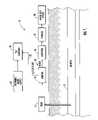
- FIG. 1is a schematic diagram of a water treatment system including an embodiment of the hydrogen sulfide scrubber according to the present invention.
- FIG. 2is a more detailed schematic diagram of the hydrogen sulfide scrubber and controller as shown in FIG. 1 .
- FIG. 3is a more detailed schematic diagram of the controller and hydrogen sulfide sensors as shown in FIG. 2 .
- FIG. 4is a schematic diagram of another embodiment of a hydrogen sulfide scrubber as shown in FIG. 2 , but having both caustic and polymeric amine supplies.
- FIG. 5is a schematic diagram of still another embodiment of the hydrogen sulfide scrubber according to the present invention.
- FIG. 6is a more detailed schematic cross-sectional view of the regenerative blower and associated venturi injector nozzle as shown in FIG. 5 .
- FIG. 7is a flow chart illustrating a method of scrubbing hydrogen sulfide according to the present invention.
- FIG. 8is a flow chart illustrating a method of retrofitting a hydrogen sulfide scrubber according to the present invention.
- the drinking water treatment system 10illustratively includes a pump 15 for pumping water from an aquifer 17 that is below ground level.
- the aquifer 17may be between 100 and 1000 feet below ground level.
- the drinking water treatment system 10also illustratively comprises an aerator 18 downstream from the pump 15 for generating an outlet water flow 20 and a hydrogen sulfide-containing gas flow 22 by extracting hydrogen sulfide from the water.
- a sanitizer 30 for sanitizing the outlet water flow 20is connected downstream from the aerator 18 to make drinking water.
- the sanitizer 30may, for example, be provided by a chlorinator, ultra-violet light exposure, or other sanitizing processes as understood by those skilled in the art.
- the drinking water treatment system 10may include a storage facility 32 for storing the sanitized water before it is dispensed to the community through a water distribution system 34 .
- the drinking water treatment system 10may include processing stages that have been omitted for clarity as needed to treat water in different communities, e.g., fluorination and filtration, as understood by those skilled in the art.
- the drinking water treatment system 10further illustratively comprises a hydrogen sulfide scrubber 40 for scrubbing the hydrogen sulfide-containing gas flow 22 from the aerator 18 .
- the hydrogen sulfide scrubber 40includes a first scrubber tank 42 a and a second scrubber tank 42 b.
- the first scrubber tank 42 aillustratively includes a gas flow inlet 43 connected to the aerator 18 to receive the hydrogen sulfide-containing gas flow 22 therefrom.
- a gas flow outlet 47is illustratively included at an upper portion of the first scrubber tank 42 a .
- the second scrubber tank 42 billustratively includes a gas flow inlet 45 connected to the gas flow outlet 47 of the first scrubber tank 42 a via a gas flow line 49 .
- the second scrubber tank 42 bfurther includes a gas flow outlet 48 at an upper portion thereof from which the treated gas flow is discharged to the atmosphere.
- Scrubber media 46 a , 46 bare illustratively contained within the first and second scrubber tanks 42 a , 42 b .
- the scrubber media 46 a , 46 bmay, for example, be provided by generally lightweight and hollow spheres made of polypropylene material. Such spheres are available from Tri-Pac of Raleigh, N.C. under the trade name Tri-Packs®. Other scrubbing media is also contemplated by the present invention.
- the hydrogen sulfide scrubber 40further illustratively comprises first and second scrubbing solution circulators 50 a , 50 b connected to each of the first and second scrubber tanks 42 a , 42 b .
- the first scrubbing solution circulator 50 auses a first scrubbing solution 53 a and the second scrubbing solution circulator 50 b uses a second scrubbing solution 53 b.
- the scrubbing solution circulators 50 a , 50 binclude dispensers 52 a , 52 b for dispensing the first and second scrubbing solutions 53 a , 53 b into contact with the scrubber media 46 a , 46 b .
- the scrubbing solution circulators 50 a , 50 balso include sumps 56 a , 56 b for collecting the first and second scrubbing solutions 53 a , 53 b after contact with the scrubber media 46 a , 46 b , and circulating pumps 58 a , 58 b for circulating the first and second scrubbing solutions from the sumps back to the dispensers 52 a , 52 b after contact with the scrubber media.
- the scrubbing solution circulators 50 a , 50 binclude circulator lines 55 a , 55 b connected between the sump 56 a , 56 b and the dispensers 52 a , 52 b .
- the circulating pumps 58 a , 58 bmay be connected to the circulator lines 55 a , 55 b to circulate the first and second scrubbing solutions 53 a , 53 b from the sumps 56 a , 56 b to the dispensers 52 a , 52 b.
- the drinking water treatment system 10is but one example of the use of the hydrogen sulfide scrubber 40 in accordance with the present invention.
- the hydrogen sulfide scrubber 40could also be used for treating hydrogen sulfide-containing gas from wastewater.
- Other applications of the hydrogen sulfide scrubber 40will be readily understood by those skilled in the art.
- the hydrogen sulfide scrubber 40further illustratively comprises a polymeric amine compound supply 60 for supplying a polymeric amine reagent 62 to the second scrubbing solution 53 b .
- the polymeric amine 62captures the hydrogen sulfide into the scrubber solution 53 a , 53 b , as well as mercaptans.
- SULFA-CLEAR®For example, Weatherford of Houston, Tex. offers a line of chemicals under the designation SULFA-CLEAR® to remove nuisance hydrogen sulfide from natural gas, crude oil, LPG, NGL, waster water, ground water, and aqueous systems.
- SULFA-CLEAR®is formulated for absorption hydrogen sulfide and volatile mercaptans. The combination of multiple amine sites and organophilic properties allows for fast, efficient abatement of these problem compounds.
- SULFA-CLEAR®absorbs and reacts with the hydrogen sulfide and mercaptans to form water-soluble and non-volatile poly sulfides that are readily consumed in the downstream waste treatment process. The spent reaction products may also help reduce corrosion.
- SULFA-CLEAR®The chemical composition and properties of SULFA-CLEAR® are further described in U.S. Pat. No. 5,488,103, the entire contents of which are incorporated herein by reference. Applicants have also found that the particular polymeric amine reagent identified as SULFA-CLEAR® 5167 may be especially useful, although other similar products are also contemplated by the present invention.
- Liquid scavengersare identified as the most effective and versatile reagents, and can be used with chemical injection systems incorporating multiple injection points, atomizers, static mixers, downstream separators, wet scrubbers, drip feed systems, and vapor phase scrubbers for spent product separation and removal. They can also be used in bubble towers and absorption towers for maximum intimacy of liquid droplets with gas molecules.
- a supply pump 64may be connected to the polymeric amine supply 60 to pump the polymeric amine reagent 62 from a storage container 66 to the second scrubbing solution circulator 50 b .
- a line 68illustratively extends between the storage container 66 and the second scrubber tank 42 b to deliver the polymeric amine 62 to the second scrubbing solution 53 b .
- the polymeric amine supply 60is illustratively supplied to only the second scrubbing solution circulator 50 b.
- the hydrogen sulfide scrubber 40further illustratively comprises a scrubbing solution charging line 70 for supplying a portion of the second scrubbing solution 53 b to the first scrubbing solution 53 a to charge the first scrubbing solution with the polymeric amine 62 .
- the scrubbing solution charging line 70is illustratively connected between the first scrubber tank 42 a and second scrubber tank 42 b .
- a charging line pump 72is connected to the scrubber solution charging line 70 to pump a portion of the second scrubbing solution 53 b from the sump 56 b of the second scrubber tank 42 b to the sump 56 a of the first scrubber tank 42 a .
- the pump 72may not be needed in other embodiments, such as where the scrubbing solution is diverted from the pressure side of the circulating pump 58 b , for example.
- a make-up water supply 24 a , 24 bis illustratively connected to the each of the first and second scrubber tanks 42 a , 42 b to supply make-up water to the first and second scrubbing solutions 53 a , 53 b .
- make-up watermay only be supplied to the second scrubber tank under normal operating conditions.
- the second make-up water supply 24 bmay supply make-up water at a desired rate depending on the size of the scrubber tanks 42 a , 42 b , e.g., 6 gallons per minute (gpm).
- the scrubbing solution charging line 70may supply the first scrubbing solution 53 a with a portion of the second scrubbing solution 53 b at a substantially similar rate. Further, when supplying the polymeric amine 62 to the second scrubbing solution 53 b , the make-up water supply 24 a of the first scrubber tank 42 a may be turned off at the first make-up water valve 25 a , while the second make-up water valve 25 b is set to 6 gpm, for example.
- the first and second scrubber tanks 42 a , 42 bmay further illustratively include overflow lines 28 a , 28 b for maintaining the first and second scrubbing solutions 53 a , 53 b at desired levels within the sumps 56 a , 56 b.
- the controller 80is illustratively connected to the supply pump 64 to regulate the amount of polymeric amine 62 to be supplied to the second scrubbing solution 53 b .
- the controller 80illustratively includes a housing 89 containing processing electronics 81 , such as mounted on a circuit board for example, for controlling the polymeric amine supply 60 as will be readily understood by those skilled in the art.
- Hydrogen sulfide sensorsincluding an inlet gas sensor 82 a and a discharge gas sensor 82 b , are connected to the processing electronics 81 . Accordingly, the controller 80 controls the polymeric amine supply 60 based upon the inlet gas sensor 82 a and discharge gas sensor 82 b.
- the inlet gas sensor 82 aincludes a sampling tube 83 a having an inlet 84 a that is illustratively connected in fluid communication with the hydrogen sulfide-containing gas flow 22 from the aerator 18 and into the inlet 43 of the first scrubber tank.
- the sampling tube 83 a of the inlet gas sensor 82 aalso illustratively includes an outlet 85 a .
- a hydrogen sulfide sensing device 86 ais positioned remote from the aerator 18 illustratively within the controller housing 89 , and is connected to the outlet 85 a of the sampling tube 83 a.
- the discharge gas sensor 82 bincludes a sampling tube 83 b having an inlet 84 b connected in fluid communication to the discharge gas flow 48 from the second scrubber tank 42 b .
- the sampling tube 83 b of the discharge gas sensor 82 balso illustratively includes an outlet 85 b .
- a hydrogen sulfide sensing device 86 bis positioned remote from the second scrubber tank 42 b and within the housing 89 , and is connected to the outlet 85 b of the sampling tube 83 b.
- a purge pump 88is provided within the controller housing 89 , and is illustratively connected to the processing electronics 81 and the sampling tubes 83 a , 83 b adjacent the outlets 85 a , 85 b .
- Condensation drain valves 87 a , 87 bare also illustratively connected to the processing electronics 81 and the sampling tubes 83 a , 83 b .
- the controller 80periodically operates the purge pump 88 and the condensation drain valves 87 a , 87 b to drain condensation from within the sampling tubes 83 a , 83 b to thereby obtain more accurate hydrogen sulfide readings as will be appreciated by those skilled in the art.
- the hydrogen sulfide scrubber 40 ′comprises a caustic supply 26 ′ illustratively connected to the first and second scrubber tanks 42 a ′, 42 b ′.
- a switchover valve arrangement 27 ′ for permitting selective alternate operation using the caustic supply 26 ′ or the polymeric amine compound supply 60 ′is illustratively included. More specifically, when use of the polymeric amine supply 60 ′ is desired, valves adjacent the caustic supply 27 a ′, 27 b ′ are closed to cut off the supply of caustic material.
- a valve 27 d ′ for the polymeric amine supply 60 ′is opened to allow the polymeric amine 62 ′ to be supplied to the second scrubbing solution 53 b ′. Further, a valve on the charging line 27 c ′ is opened to allow charging of the first scrubbing solution 53 a ′ with a portion of the second scrubbing solution 53 b′.
- make-up wateris supplied to both the first and second scrubbing solution circulators 50 a ′, 50 b ′.
- the opposite valve configurationis employed to again use the caustic.
- the other elements of the second embodiment of the hydrogen sulfide scrubber 40 ′are similar to those of the first embodiment, are identified using prime notation and require no further discussion herein.
- the retrofitting and switchover featureadvantageously permits water treatment plant operators to become familiar and gain experience with the use of the polymeric amine 62 in the water treatment process before making a commitment to retire existing caustic based equipment.
- the third embodiment of the hydrogen sulfide scrubber 40 ′′illustratively includes only a single scrubber tank 42 ′′.
- a single stage of hydrogen sulfide reductionis provided using the polymeric amine supply 60 ′′, along with a mist generator 100 for generating a scrubber solution mist 101 in the space above the scrubbing solution 53 ′′ in the sump 56 ′′ and beneath the scrubber media 46 ′′.
- the mist generator 100 ′′includes a regenerative blower 102 ′′ and a nozzle associated therewith.
- the regenerative blowergenerates a flow from the inlet 104 ′′ to the outlet 105 ′′.
- the nozzleis a venturi injection nozzle 103 ′′ having a liquid inlet 106 ′′ connected to the line 55 ′′ from the circulating pump 58 ′′.
- This nozzle 103 ′′has found to be efficient in generating the desired scrubbing solution mist 101 ′′.
- the venturi injector nozzle 103 ′′may of the type as provided by MAZZEI® Injector Corporation of Bakersfield, Calif.
- U.S. Pat. No. 5,863,128also discloses such injectors, and the entire contents of this patent are incorporated herein by reference.
- This scrubbing solution mist 101 ′′is believed to further increase the contact time and area of the hydrogen sulfide-containing gas with the polymeric amine, and thereby greatly knock down the hydrogen sulfide and mercaptans. Accordingly, even for a multi-stage scrubber as described above, it may be sufficient to provide such a mist generator 100 ′′ including the regenerative blower 102 ′′ and associated venturi injector nozzle 103 ′′ on only the first or inlet stage. Of course, those of skill in the art will appreciate that this mist generator 100 ′′ may be used on additional or all other stages as well.
- the other elements of the third embodiment of the hydrogen sulfide scrubber 40 ′′are similar to those of the first and second embodiments, are identified using double prime notation, and require no further discussion herein.
- the second scrubbing solution 53 bis circulated into contact with scrubber media 46 b in the second scrubber tank 42 b at Block 95 .
- the polymeric amine 62is supplied to the second scrubber solution 53 b .
- the first scrubber solution 53 ais charged with a portion of the second scrubber solution 53 b at Block 97 .
- hydrogen sulfide-containing gas 22is continuously received at Block 92 .
- the scrubbed gasis discharged from the second scrubber tank 42 b.
- the scrubbing solution circulators 50 a ′, 50 b ′are left unchanged.
- the make-up water supply 24 a ′ of the first scrubber tank 42 a ′is turned off and the make-up water supply 24 b ′ of the second scrubber tank 42 b ′ is reduced at Block 116 .
- the hydrogen sulfide sensors 82 a ′, 82 b ′are installed and the controller 80 ′ is installed at Block 118 .
- the methodis completed at Block 119 .
Landscapes
- Chemical & Material Sciences (AREA)
- Engineering & Computer Science (AREA)
- Analytical Chemistry (AREA)
- General Chemical & Material Sciences (AREA)
- Oil, Petroleum & Natural Gas (AREA)
- Chemical Kinetics & Catalysis (AREA)
- Gas Separation By Absorption (AREA)
- Treating Waste Gases (AREA)
Abstract
Description
Claims (47)
Priority Applications (1)
| Application Number | Priority Date | Filing Date | Title |
|---|---|---|---|
| US10/864,310US7077884B2 (en) | 2004-06-09 | 2004-06-09 | Hydrogen sulfide scrubber using polymeric amine and associated methods |
Applications Claiming Priority (1)
| Application Number | Priority Date | Filing Date | Title |
|---|---|---|---|
| US10/864,310US7077884B2 (en) | 2004-06-09 | 2004-06-09 | Hydrogen sulfide scrubber using polymeric amine and associated methods |
Publications (2)
| Publication Number | Publication Date |
|---|---|
| US20050274256A1 US20050274256A1 (en) | 2005-12-15 |
| US7077884B2true US7077884B2 (en) | 2006-07-18 |
Family
ID=35459159
Family Applications (1)
| Application Number | Title | Priority Date | Filing Date |
|---|---|---|---|
| US10/864,310Expired - LifetimeUS7077884B2 (en) | 2004-06-09 | 2004-06-09 | Hydrogen sulfide scrubber using polymeric amine and associated methods |
Country Status (1)
| Country | Link |
|---|---|
| US (1) | US7077884B2 (en) |
Cited By (4)
| Publication number | Priority date | Publication date | Assignee | Title |
|---|---|---|---|---|
| US20090180922A1 (en)* | 2008-01-10 | 2009-07-16 | Peter Robert Stewart | Fluid Conditioning Apparatus |
| US20110217218A1 (en)* | 2010-03-02 | 2011-09-08 | Exxonmobil Research And Engineering Company | Systems and Methods for Acid Gas Removal |
| DE102007054115B4 (en)* | 2007-11-10 | 2013-07-04 | Ech Elektrochemie Halle Gmbh | Method for reducing odor nuisance in waste water |
| US9296956B2 (en) | 2010-10-28 | 2016-03-29 | Chevron U.S.A. Inc. | Method for reducing mercaptans in hydrocarbons |
Families Citing this family (2)
| Publication number | Priority date | Publication date | Assignee | Title |
|---|---|---|---|---|
| US20040231513A1 (en)* | 2002-03-12 | 2004-11-25 | Perkins James A. | System for inline stripping of soil contaminants |
| US8226893B2 (en)* | 2008-06-24 | 2012-07-24 | Mclauchlan Robert A | Automated sulfur recovery loop |
Citations (31)
| Publication number | Priority date | Publication date | Assignee | Title |
|---|---|---|---|---|
| US2805734A (en)* | 1953-12-05 | 1957-09-10 | Bayer Ag | Process for preventing frost from forming in coolers for the condensation of volatile substances from moist carrier gases |
| US3387431A (en) | 1966-06-13 | 1968-06-11 | Gerald H. Siebert | Desulfurizing of water |
| US3780499A (en)* | 1970-10-15 | 1973-12-25 | Metallgesellschaft Ag | System for the liquid-phase removal of a component from the gas stream especially the absorption of sulfur trioxide in sulfuric acid |
| US4029751A (en)* | 1975-05-05 | 1977-06-14 | Metallgesellschaft Aktiengesellschaft | Process for producing sulfuric acid |
| US4508545A (en) | 1983-09-19 | 1985-04-02 | Deloach Walter W | Closed loop water treating system and method |
| US5061373A (en) | 1988-07-29 | 1991-10-29 | Union Oil Company Of California | Process for treating condensate of steam derived from geothermal brine |
| US5128049A (en) | 1991-01-22 | 1992-07-07 | Gatlin Larry W | Hydrogen sulfide removal process |
| US5135684A (en) | 1989-05-05 | 1992-08-04 | Framo Development (Uk) Limited | Multiphase process mixing and measuring system |
| US5288728A (en) | 1992-09-17 | 1994-02-22 | Eastman Kodak Company | Process for recovering silver from photographic solutions |
| US5314672A (en) | 1992-05-22 | 1994-05-24 | Sweetchem Corp. | Composition and method for sweetening hydrocarbons |
| US5347003A (en) | 1993-03-05 | 1994-09-13 | Quaker Chemical Corporation | Methods for regenerating a sulfur scavenging compound from a product of a sulfur scavenging reaction |
| US5354459A (en) | 1993-03-19 | 1994-10-11 | Jerry Smith | Apparatus and method for removing odorous sulfur compounds from potable water |
| US5356458A (en) | 1991-08-12 | 1994-10-18 | Clearwater Industries Corporation | Computerized chemical injection system for hydrogen sulfide control in a waste water stream |
| US5405591A (en) | 1994-01-27 | 1995-04-11 | Galtec Canada, Ltd. | Method for removing sulphide(s) from sour gas |
| US5462721A (en) | 1994-08-24 | 1995-10-31 | Crescent Holdings Limited | Hydrogen sulfide scavenging process |
| US5480860A (en) | 1988-12-23 | 1996-01-02 | Petrolite Corporation | Methods for reducing sulfides in sewage gas |
| US5488103A (en) | 1991-07-11 | 1996-01-30 | Gatlin; Larry W. | Hydrogen sulfide converter |
| US5507848A (en)* | 1993-03-12 | 1996-04-16 | Beckman; Eric J. | Polymers capable of reversibly complexing acid gases and a method of using the same |
| US5549820A (en) | 1994-03-04 | 1996-08-27 | Eastman Kodak Company | Apparatus for removing a component from solution |
| US5554349A (en) | 1992-10-09 | 1996-09-10 | Banker Hughes Incorporated | Process for scavenging H2 S by mixtures of hexahydrotriazines |
| US5667651A (en) | 1995-07-13 | 1997-09-16 | Bryan; Avron | Apparatus and associated method for reducing an undesired constituent of gas associated with wastewater and having sensor fault detection |
| US5667558A (en) | 1995-07-13 | 1997-09-16 | Adapco, Inc. | Apparatus and associated method for reducing an undesired constituent of gas associated with wastewater |
| US5688478A (en) | 1994-08-24 | 1997-11-18 | Crescent Holdings Limited | Method for scavenging sulfides |
| US5698171A (en) | 1996-01-10 | 1997-12-16 | Quaker Chemical Corporation | Regenerative method for removing sulfides from gas streams |
| US5756058A (en)* | 1993-11-16 | 1998-05-26 | Sumitomo Heavy Industries, Ltd. | Process for purifying sulfur oxides-containing gas |
| US5863128A (en) | 1997-12-04 | 1999-01-26 | Mazzei; Angelo L. | Mixer-injectors with twisting and straightening vanes |
| US5885538A (en) | 1997-07-02 | 1999-03-23 | Quaker Chemical Corporation | Method and composition for the regeneration of an aminal compound |
| US6063346A (en) | 1998-06-05 | 2000-05-16 | Intevep, S. A. | Process for scavenging hydrogen sulfide and mercaptan contaminants from a fluid |
| US6142383A (en) | 1998-04-08 | 2000-11-07 | Hinsilblon Laboratories | Method of waterless large scale dispersion of essential oils and apparatus therefor |
| US6551382B1 (en)* | 2002-05-24 | 2003-04-22 | Clyde N. Richards | Hot-humid/cold gas scrubbing process and apparatus |
| US20040055463A1 (en) | 2002-09-25 | 2004-03-25 | Precision Control Technology, Inc. | Drinking water treatment system including hydrogen sulfide scrubber using triazine compound and associated methods |
- 2004
- 2004-06-09USUS10/864,310patent/US7077884B2/ennot_activeExpired - Lifetime
Patent Citations (33)
| Publication number | Priority date | Publication date | Assignee | Title |
|---|---|---|---|---|
| US2805734A (en)* | 1953-12-05 | 1957-09-10 | Bayer Ag | Process for preventing frost from forming in coolers for the condensation of volatile substances from moist carrier gases |
| US3387431A (en) | 1966-06-13 | 1968-06-11 | Gerald H. Siebert | Desulfurizing of water |
| US3780499A (en)* | 1970-10-15 | 1973-12-25 | Metallgesellschaft Ag | System for the liquid-phase removal of a component from the gas stream especially the absorption of sulfur trioxide in sulfuric acid |
| US4029751A (en)* | 1975-05-05 | 1977-06-14 | Metallgesellschaft Aktiengesellschaft | Process for producing sulfuric acid |
| US4508545A (en) | 1983-09-19 | 1985-04-02 | Deloach Walter W | Closed loop water treating system and method |
| US5061373A (en) | 1988-07-29 | 1991-10-29 | Union Oil Company Of California | Process for treating condensate of steam derived from geothermal brine |
| US5480860A (en) | 1988-12-23 | 1996-01-02 | Petrolite Corporation | Methods for reducing sulfides in sewage gas |
| US5135684A (en) | 1989-05-05 | 1992-08-04 | Framo Development (Uk) Limited | Multiphase process mixing and measuring system |
| US5128049A (en) | 1991-01-22 | 1992-07-07 | Gatlin Larry W | Hydrogen sulfide removal process |
| US5488103A (en) | 1991-07-11 | 1996-01-30 | Gatlin; Larry W. | Hydrogen sulfide converter |
| US5356458A (en) | 1991-08-12 | 1994-10-18 | Clearwater Industries Corporation | Computerized chemical injection system for hydrogen sulfide control in a waste water stream |
| US5314672A (en) | 1992-05-22 | 1994-05-24 | Sweetchem Corp. | Composition and method for sweetening hydrocarbons |
| US5288728A (en) | 1992-09-17 | 1994-02-22 | Eastman Kodak Company | Process for recovering silver from photographic solutions |
| US5554349A (en) | 1992-10-09 | 1996-09-10 | Banker Hughes Incorporated | Process for scavenging H2 S by mixtures of hexahydrotriazines |
| US5347003A (en) | 1993-03-05 | 1994-09-13 | Quaker Chemical Corporation | Methods for regenerating a sulfur scavenging compound from a product of a sulfur scavenging reaction |
| US5507848A (en)* | 1993-03-12 | 1996-04-16 | Beckman; Eric J. | Polymers capable of reversibly complexing acid gases and a method of using the same |
| US5354459A (en) | 1993-03-19 | 1994-10-11 | Jerry Smith | Apparatus and method for removing odorous sulfur compounds from potable water |
| US5756058A (en)* | 1993-11-16 | 1998-05-26 | Sumitomo Heavy Industries, Ltd. | Process for purifying sulfur oxides-containing gas |
| US5405591A (en) | 1994-01-27 | 1995-04-11 | Galtec Canada, Ltd. | Method for removing sulphide(s) from sour gas |
| US5478536A (en) | 1994-01-27 | 1995-12-26 | Galtec Canada Ltd. | Method and system for removing sulphide(s) from sour gas |
| US5549820A (en) | 1994-03-04 | 1996-08-27 | Eastman Kodak Company | Apparatus for removing a component from solution |
| US5688478A (en) | 1994-08-24 | 1997-11-18 | Crescent Holdings Limited | Method for scavenging sulfides |
| US5462721A (en) | 1994-08-24 | 1995-10-31 | Crescent Holdings Limited | Hydrogen sulfide scavenging process |
| US5667558A (en) | 1995-07-13 | 1997-09-16 | Adapco, Inc. | Apparatus and associated method for reducing an undesired constituent of gas associated with wastewater |
| US5667651A (en) | 1995-07-13 | 1997-09-16 | Bryan; Avron | Apparatus and associated method for reducing an undesired constituent of gas associated with wastewater and having sensor fault detection |
| US5698171A (en) | 1996-01-10 | 1997-12-16 | Quaker Chemical Corporation | Regenerative method for removing sulfides from gas streams |
| US5885538A (en) | 1997-07-02 | 1999-03-23 | Quaker Chemical Corporation | Method and composition for the regeneration of an aminal compound |
| US5863128A (en) | 1997-12-04 | 1999-01-26 | Mazzei; Angelo L. | Mixer-injectors with twisting and straightening vanes |
| US6142383A (en) | 1998-04-08 | 2000-11-07 | Hinsilblon Laboratories | Method of waterless large scale dispersion of essential oils and apparatus therefor |
| US6063346A (en) | 1998-06-05 | 2000-05-16 | Intevep, S. A. | Process for scavenging hydrogen sulfide and mercaptan contaminants from a fluid |
| US6551382B1 (en)* | 2002-05-24 | 2003-04-22 | Clyde N. Richards | Hot-humid/cold gas scrubbing process and apparatus |
| US20040055463A1 (en) | 2002-09-25 | 2004-03-25 | Precision Control Technology, Inc. | Drinking water treatment system including hydrogen sulfide scrubber using triazine compound and associated methods |
| US6773582B2 (en)* | 2002-09-25 | 2004-08-10 | Precision Control Technology, Inc. | Drinking water treatment system including hydrogen sulfide scrubber using triazine compound and associated methods |
Non-Patent Citations (11)
| Title |
|---|
| 2001 Annual Drinking Water Report, Utilities Water Division, Orange County Government, Florida. |
| Champion Technologies, H<SUB>2</SUB>S Scavenging Technology, available at www.champ-tech.com/h2scavenging.asp. |
| Gary J. Nagl, Article entitled "Controlling H<SUB>2</SUB>S Emissions in Geothermal Power Plants", available at www.gtp-merichem.com/whats<SUB>-</SUB>geo<SUB>-</SUB>euro.htm. |
| Industrial Air Solutions, 2001, Gas Wet Scrubber Tower Packing Media, available at www.industrialairsolutions.com/wet-scrubbers/tripac.htm. |
| Met-Pro Corporation, 2000, Duall Division Various Fume and Gas Wet Scrubbers, available at www.met-pro.com/html/duall.htm. |
| Q<SUP>2 </SUP>Technologies, 2001, ENVIRO-SCRUB(R) Process, available at www.q2technologies.com/escrub.htm. |
| Q<SUP>2 </SUP>Technologies, 2001, Enviro-Tek(TM) Process, available at www.q2technologies.com/etek.htm. |
| Quaker Chemical Corporation, 2000, Customer Processes & Applications, available at www.quakerchem.com/products/by<SUB>-</SUB>app.htm. |
| Quaker Chemical Corporation, 2000, Worldwide Innovations, available at www.quakerchem.com/products/product<SUB>-</SUB>desc.htm. |
| Sulfa-Clear 8640 Hydrogen Sulfide Scavenger, Technical Data, Clearwater, Jun. 2003. |
| Sulfa-Clear, Safely and Effectively Removes H<SUB>2</SUB>S , Weatherford, 2004. |
Cited By (6)
| Publication number | Priority date | Publication date | Assignee | Title |
|---|---|---|---|---|
| DE102007054115B4 (en)* | 2007-11-10 | 2013-07-04 | Ech Elektrochemie Halle Gmbh | Method for reducing odor nuisance in waste water |
| US20090180922A1 (en)* | 2008-01-10 | 2009-07-16 | Peter Robert Stewart | Fluid Conditioning Apparatus |
| US8136798B2 (en)* | 2008-01-10 | 2012-03-20 | Peter Robert Stewart | Fluid conditioning apparatus |
| USRE46101E1 (en)* | 2008-01-10 | 2016-08-16 | Fuel Vapor Systems, Inc. | Fluid conditioning apparatus |
| US20110217218A1 (en)* | 2010-03-02 | 2011-09-08 | Exxonmobil Research And Engineering Company | Systems and Methods for Acid Gas Removal |
| US9296956B2 (en) | 2010-10-28 | 2016-03-29 | Chevron U.S.A. Inc. | Method for reducing mercaptans in hydrocarbons |
Also Published As
| Publication number | Publication date |
|---|---|
| US20050274256A1 (en) | 2005-12-15 |
Similar Documents
| Publication | Publication Date | Title |
|---|---|---|
| US4696739A (en) | Water purification apparatus | |
| US5560831A (en) | Method and apparatus for treating water used for washing agricultural products including coagulation and ozone treatment | |
| US8919573B2 (en) | Water purification system and method | |
| US4808319A (en) | Method for removing a slime deposit from packing material inside a tower | |
| CA2172622C (en) | Control of iron deposition in borehole pumps | |
| JP2002167813A (en) | Building rainwater utilization method and building rainwater utilization system | |
| US12258288B2 (en) | Integrated biogas treatment and carbon dioxide based disinfection for water treatment | |
| US20100122945A1 (en) | Grey water conservation mechanism | |
| RU2650168C2 (en) | Method and system for the treatment of produced water and fluids with chlorine dioxide for re-use | |
| US6773582B2 (en) | Drinking water treatment system including hydrogen sulfide scrubber using triazine compound and associated methods | |
| US7077884B2 (en) | Hydrogen sulfide scrubber using polymeric amine and associated methods | |
| US6432312B1 (en) | Closed system for rearing aquatic life | |
| US6287469B1 (en) | Home wastewater treatment plant | |
| KR20090107468A (en) | Treatment apparatus for riverside filtration using oxidized paper and biological activated carbon filter paper | |
| KR101868046B1 (en) | Hybrid odor removal having function of aeration | |
| US20060144229A1 (en) | Apparatus and method for pressurising biogas in a gas washer | |
| US6306197B1 (en) | Isopropyl alcohol scrubbing system | |
| KR20110001685A (en) | External Immersion Membrane System | |
| KR100615455B1 (en) | High pressure cleaning device for pipe using ozone water | |
| JP5594774B2 (en) | Gas dissolution mechanism | |
| JP5183538B2 (en) | Surplus sludge reduction device | |
| US20240400925A1 (en) | Oxidizing compositions for removing sulfur compounds from hydrocarbon fuels and wastewater | |
| US20240400426A1 (en) | Oxidizing compositions for removing sulfur compounds from hydrocarbon fuels and wastewater | |
| US20240400924A1 (en) | Oxidizing compositions for removing sulfur compounds from hydrocarbon fuels and wastewater | |
| US20240399301A1 (en) | Oxidizing compositions for removing sulfur compounds from hydrocarbon fuels and wastewater |
Legal Events
| Date | Code | Title | Description |
|---|---|---|---|
| AS | Assignment | Owner name:PRECISION CONTROL TECHNOLOGY, INC., FLORIDA Free format text:ASSIGNMENT OF ASSIGNORS INTEREST;ASSIGNORS:DAVIS, JERRY;CHESHIRE, JAMES E.;REEL/FRAME:015499/0444 Effective date:20040608 | |
| STCF | Information on status: patent grant | Free format text:PATENTED CASE | |
| AS | Assignment | Owner name:PATRIOT CAPITAL FUNDING, INC., CONNECTICUT Free format text:SECURITY AGREEMENT;ASSIGNORS:APV ACQUISITION CORP.;ADAPCO, INC.;VECTOR DISEASE CONTROL, INC.;AND OTHERS;REEL/FRAME:017996/0309 Effective date:20060721 | |
| AS | Assignment | Owner name:Q2 TECHNOLOGIES, LLC, TEXAS Free format text:ASSIGNMENT OF ASSIGNORS INTEREST;ASSIGNOR:PRECISION CONTROL TECHNOLOGY, INC.;REEL/FRAME:021439/0950 Effective date:20080812 Owner name:PRECISION CONTROL TECHNOLOGY, INC., FLORIDA Free format text:RELEASE BY SECURED PARTY;ASSIGNOR:PATRIOT CAPITAL FUNDING, INC.;REEL/FRAME:021439/0567 Effective date:20080826 | |
| FPAY | Fee payment | Year of fee payment:4 | |
| SULP | Surcharge for late payment | ||
| FPAY | Fee payment | Year of fee payment:8 | |
| MAFP | Maintenance fee payment | Free format text:PAYMENT OF MAINTENANCE FEE, 12TH YR, SMALL ENTITY (ORIGINAL EVENT CODE: M2553) Year of fee payment:12 |