US7077327B1 - System for reading bar code symbols using bar code readers having RF signal transmission links with base stations - Google Patents
System for reading bar code symbols using bar code readers having RF signal transmission links with base stationsDownload PDFInfo
- Publication number
- US7077327B1 US7077327B1US09/346,859US34685999AUS7077327B1US 7077327 B1US7077327 B1US 7077327B1US 34685999 AUS34685999 AUS 34685999AUS 7077327 B1US7077327 B1US 7077327B1
- Authority
- US
- United States
- Prior art keywords
- bar code
- code symbol
- data
- reading device
- range
- Prior art date
- Legal status (The legal status is an assumption and is not a legal conclusion. Google has not performed a legal analysis and makes no representation as to the accuracy of the status listed.)
- Expired - Fee Related
Links
Images


Classifications
- G—PHYSICS
- G02—OPTICS
- G02B—OPTICAL ELEMENTS, SYSTEMS OR APPARATUS
- G02B26/00—Optical devices or arrangements for the control of light using movable or deformable optical elements
- G02B26/08—Optical devices or arrangements for the control of light using movable or deformable optical elements for controlling the direction of light
- G02B26/10—Scanning systems
- G02B26/106—Scanning systems having diffraction gratings as scanning elements, e.g. holographic scanners
- G—PHYSICS
- G06—COMPUTING OR CALCULATING; COUNTING
- G06K—GRAPHICAL DATA READING; PRESENTATION OF DATA; RECORD CARRIERS; HANDLING RECORD CARRIERS
- G06K17/00—Methods or arrangements for effecting co-operative working between equipments covered by two or more of main groups G06K1/00 - G06K15/00, e.g. automatic card files incorporating conveying and reading operations
- G06K17/0022—Methods or arrangements for effecting co-operative working between equipments covered by two or more of main groups G06K1/00 - G06K15/00, e.g. automatic card files incorporating conveying and reading operations arrangements or provisions for transferring data to distant stations, e.g. from a sensing device
- G—PHYSICS
- G06—COMPUTING OR CALCULATING; COUNTING
- G06K—GRAPHICAL DATA READING; PRESENTATION OF DATA; RECORD CARRIERS; HANDLING RECORD CARRIERS
- G06K7/00—Methods or arrangements for sensing record carriers, e.g. for reading patterns
- G06K7/10—Methods or arrangements for sensing record carriers, e.g. for reading patterns by electromagnetic radiation, e.g. optical sensing; by corpuscular radiation
- G06K7/10544—Methods or arrangements for sensing record carriers, e.g. for reading patterns by electromagnetic radiation, e.g. optical sensing; by corpuscular radiation by scanning of the records by radiation in the optical part of the electromagnetic spectrum
- G06K7/10554—Moving beam scanning
- G06K7/10564—Light sources
- G06K7/10584—Source control
- G—PHYSICS
- G06—COMPUTING OR CALCULATING; COUNTING
- G06K—GRAPHICAL DATA READING; PRESENTATION OF DATA; RECORD CARRIERS; HANDLING RECORD CARRIERS
- G06K7/00—Methods or arrangements for sensing record carriers, e.g. for reading patterns
- G06K7/10—Methods or arrangements for sensing record carriers, e.g. for reading patterns by electromagnetic radiation, e.g. optical sensing; by corpuscular radiation
- G06K7/10544—Methods or arrangements for sensing record carriers, e.g. for reading patterns by electromagnetic radiation, e.g. optical sensing; by corpuscular radiation by scanning of the records by radiation in the optical part of the electromagnetic spectrum
- G06K7/10554—Moving beam scanning
- G06K7/10594—Beam path
- G06K7/10603—Basic scanning using moving elements
- G06K7/10663—Basic scanning using moving elements using hologram
- G—PHYSICS
- G06—COMPUTING OR CALCULATING; COUNTING
- G06K—GRAPHICAL DATA READING; PRESENTATION OF DATA; RECORD CARRIERS; HANDLING RECORD CARRIERS
- G06K7/00—Methods or arrangements for sensing record carriers, e.g. for reading patterns
- G06K7/10—Methods or arrangements for sensing record carriers, e.g. for reading patterns by electromagnetic radiation, e.g. optical sensing; by corpuscular radiation
- G06K7/10544—Methods or arrangements for sensing record carriers, e.g. for reading patterns by electromagnetic radiation, e.g. optical sensing; by corpuscular radiation by scanning of the records by radiation in the optical part of the electromagnetic spectrum
- G06K7/10554—Moving beam scanning
- G06K7/10594—Beam path
- G06K7/10603—Basic scanning using moving elements
- G06K7/10673—Parallel lines
- G—PHYSICS
- G06—COMPUTING OR CALCULATING; COUNTING
- G06K—GRAPHICAL DATA READING; PRESENTATION OF DATA; RECORD CARRIERS; HANDLING RECORD CARRIERS
- G06K7/00—Methods or arrangements for sensing record carriers, e.g. for reading patterns
- G06K7/10—Methods or arrangements for sensing record carriers, e.g. for reading patterns by electromagnetic radiation, e.g. optical sensing; by corpuscular radiation
- G06K7/10544—Methods or arrangements for sensing record carriers, e.g. for reading patterns by electromagnetic radiation, e.g. optical sensing; by corpuscular radiation by scanning of the records by radiation in the optical part of the electromagnetic spectrum
- G06K7/10554—Moving beam scanning
- G06K7/10594—Beam path
- G06K7/10683—Arrangement of fixed elements
- G06K7/10693—Arrangement of fixed elements for omnidirectional scanning
- G—PHYSICS
- G06—COMPUTING OR CALCULATING; COUNTING
- G06K—GRAPHICAL DATA READING; PRESENTATION OF DATA; RECORD CARRIERS; HANDLING RECORD CARRIERS
- G06K7/00—Methods or arrangements for sensing record carriers, e.g. for reading patterns
- G06K7/10—Methods or arrangements for sensing record carriers, e.g. for reading patterns by electromagnetic radiation, e.g. optical sensing; by corpuscular radiation
- G06K7/10544—Methods or arrangements for sensing record carriers, e.g. for reading patterns by electromagnetic radiation, e.g. optical sensing; by corpuscular radiation by scanning of the records by radiation in the optical part of the electromagnetic spectrum
- G06K7/10554—Moving beam scanning
- G06K7/10594—Beam path
- G06K7/10683—Arrangement of fixed elements
- G06K7/10702—Particularities of propagating elements, e.g. lenses, mirrors
- G—PHYSICS
- G06—COMPUTING OR CALCULATING; COUNTING
- G06K—GRAPHICAL DATA READING; PRESENTATION OF DATA; RECORD CARRIERS; HANDLING RECORD CARRIERS
- G06K7/00—Methods or arrangements for sensing record carriers, e.g. for reading patterns
- G06K7/10—Methods or arrangements for sensing record carriers, e.g. for reading patterns by electromagnetic radiation, e.g. optical sensing; by corpuscular radiation
- G06K7/10544—Methods or arrangements for sensing record carriers, e.g. for reading patterns by electromagnetic radiation, e.g. optical sensing; by corpuscular radiation by scanning of the records by radiation in the optical part of the electromagnetic spectrum
- G06K7/10792—Special measures in relation to the object to be scanned
- G06K7/10801—Multidistance reading
- G06K7/10811—Focalisation
- G—PHYSICS
- G06—COMPUTING OR CALCULATING; COUNTING
- G06K—GRAPHICAL DATA READING; PRESENTATION OF DATA; RECORD CARRIERS; HANDLING RECORD CARRIERS
- G06K7/00—Methods or arrangements for sensing record carriers, e.g. for reading patterns
- G06K7/10—Methods or arrangements for sensing record carriers, e.g. for reading patterns by electromagnetic radiation, e.g. optical sensing; by corpuscular radiation
- G06K7/10544—Methods or arrangements for sensing record carriers, e.g. for reading patterns by electromagnetic radiation, e.g. optical sensing; by corpuscular radiation by scanning of the records by radiation in the optical part of the electromagnetic spectrum
- G06K7/10821—Methods or arrangements for sensing record carriers, e.g. for reading patterns by electromagnetic radiation, e.g. optical sensing; by corpuscular radiation by scanning of the records by radiation in the optical part of the electromagnetic spectrum further details of bar or optical code scanning devices
- G06K7/10851—Circuits for pulse shaping, amplifying, eliminating noise signals, checking the function of the sensing device
- G—PHYSICS
- G06—COMPUTING OR CALCULATING; COUNTING
- G06K—GRAPHICAL DATA READING; PRESENTATION OF DATA; RECORD CARRIERS; HANDLING RECORD CARRIERS
- G06K7/00—Methods or arrangements for sensing record carriers, e.g. for reading patterns
- G06K7/10—Methods or arrangements for sensing record carriers, e.g. for reading patterns by electromagnetic radiation, e.g. optical sensing; by corpuscular radiation
- G06K7/10544—Methods or arrangements for sensing record carriers, e.g. for reading patterns by electromagnetic radiation, e.g. optical sensing; by corpuscular radiation by scanning of the records by radiation in the optical part of the electromagnetic spectrum
- G06K7/10821—Methods or arrangements for sensing record carriers, e.g. for reading patterns by electromagnetic radiation, e.g. optical sensing; by corpuscular radiation by scanning of the records by radiation in the optical part of the electromagnetic spectrum further details of bar or optical code scanning devices
- G06K7/10861—Methods or arrangements for sensing record carriers, e.g. for reading patterns by electromagnetic radiation, e.g. optical sensing; by corpuscular radiation by scanning of the records by radiation in the optical part of the electromagnetic spectrum further details of bar or optical code scanning devices sensing of data fields affixed to objects or articles, e.g. coded labels
- G06K7/10871—Methods or arrangements for sensing record carriers, e.g. for reading patterns by electromagnetic radiation, e.g. optical sensing; by corpuscular radiation by scanning of the records by radiation in the optical part of the electromagnetic spectrum further details of bar or optical code scanning devices sensing of data fields affixed to objects or articles, e.g. coded labels randomly oriented data-fields, code-marks therefore, e.g. concentric circles-code
- G—PHYSICS
- G06—COMPUTING OR CALCULATING; COUNTING
- G06K—GRAPHICAL DATA READING; PRESENTATION OF DATA; RECORD CARRIERS; HANDLING RECORD CARRIERS
- G06K7/00—Methods or arrangements for sensing record carriers, e.g. for reading patterns
- G06K7/10—Methods or arrangements for sensing record carriers, e.g. for reading patterns by electromagnetic radiation, e.g. optical sensing; by corpuscular radiation
- G06K7/10544—Methods or arrangements for sensing record carriers, e.g. for reading patterns by electromagnetic radiation, e.g. optical sensing; by corpuscular radiation by scanning of the records by radiation in the optical part of the electromagnetic spectrum
- G06K7/10821—Methods or arrangements for sensing record carriers, e.g. for reading patterns by electromagnetic radiation, e.g. optical sensing; by corpuscular radiation by scanning of the records by radiation in the optical part of the electromagnetic spectrum further details of bar or optical code scanning devices
- G06K7/10881—Methods or arrangements for sensing record carriers, e.g. for reading patterns by electromagnetic radiation, e.g. optical sensing; by corpuscular radiation by scanning of the records by radiation in the optical part of the electromagnetic spectrum further details of bar or optical code scanning devices constructional details of hand-held scanners
- G06K7/10891—Methods or arrangements for sensing record carriers, e.g. for reading patterns by electromagnetic radiation, e.g. optical sensing; by corpuscular radiation by scanning of the records by radiation in the optical part of the electromagnetic spectrum further details of bar or optical code scanning devices constructional details of hand-held scanners the scanner to be worn on a finger or on a wrist
- G—PHYSICS
- G06—COMPUTING OR CALCULATING; COUNTING
- G06K—GRAPHICAL DATA READING; PRESENTATION OF DATA; RECORD CARRIERS; HANDLING RECORD CARRIERS
- G06K7/00—Methods or arrangements for sensing record carriers, e.g. for reading patterns
- G06K7/10—Methods or arrangements for sensing record carriers, e.g. for reading patterns by electromagnetic radiation, e.g. optical sensing; by corpuscular radiation
- G06K7/10544—Methods or arrangements for sensing record carriers, e.g. for reading patterns by electromagnetic radiation, e.g. optical sensing; by corpuscular radiation by scanning of the records by radiation in the optical part of the electromagnetic spectrum
- G06K7/10821—Methods or arrangements for sensing record carriers, e.g. for reading patterns by electromagnetic radiation, e.g. optical sensing; by corpuscular radiation by scanning of the records by radiation in the optical part of the electromagnetic spectrum further details of bar or optical code scanning devices
- G06K7/10881—Methods or arrangements for sensing record carriers, e.g. for reading patterns by electromagnetic radiation, e.g. optical sensing; by corpuscular radiation by scanning of the records by radiation in the optical part of the electromagnetic spectrum further details of bar or optical code scanning devices constructional details of hand-held scanners
- G06K7/109—Methods or arrangements for sensing record carriers, e.g. for reading patterns by electromagnetic radiation, e.g. optical sensing; by corpuscular radiation by scanning of the records by radiation in the optical part of the electromagnetic spectrum further details of bar or optical code scanning devices constructional details of hand-held scanners adaptations to make the hand-held scanner useable as a fixed scanner
- G—PHYSICS
- G06—COMPUTING OR CALCULATING; COUNTING
- G06K—GRAPHICAL DATA READING; PRESENTATION OF DATA; RECORD CARRIERS; HANDLING RECORD CARRIERS
- G06K7/00—Methods or arrangements for sensing record carriers, e.g. for reading patterns
- G06K7/10—Methods or arrangements for sensing record carriers, e.g. for reading patterns by electromagnetic radiation, e.g. optical sensing; by corpuscular radiation
- G06K7/14—Methods or arrangements for sensing record carriers, e.g. for reading patterns by electromagnetic radiation, e.g. optical sensing; by corpuscular radiation using light without selection of wavelength, e.g. sensing reflected white light
- G06K7/1404—Methods for optical code recognition
- G06K7/1439—Methods for optical code recognition including a method step for retrieval of the optical code
- G06K7/1443—Methods for optical code recognition including a method step for retrieval of the optical code locating of the code in an image
- G—PHYSICS
- G06—COMPUTING OR CALCULATING; COUNTING
- G06K—GRAPHICAL DATA READING; PRESENTATION OF DATA; RECORD CARRIERS; HANDLING RECORD CARRIERS
- G06K7/00—Methods or arrangements for sensing record carriers, e.g. for reading patterns
- G06K7/10—Methods or arrangements for sensing record carriers, e.g. for reading patterns by electromagnetic radiation, e.g. optical sensing; by corpuscular radiation
- G06K2007/10524—Hand-held scanners
- G06K2007/10534—Scanner to be worn on a finger or on a wrist
- G—PHYSICS
- G06—COMPUTING OR CALCULATING; COUNTING
- G06K—GRAPHICAL DATA READING; PRESENTATION OF DATA; RECORD CARRIERS; HANDLING RECORD CARRIERS
- G06K2207/00—Other aspects
- G06K2207/1012—Special detection of object
- G—PHYSICS
- G06—COMPUTING OR CALCULATING; COUNTING
- G06K—GRAPHICAL DATA READING; PRESENTATION OF DATA; RECORD CARRIERS; HANDLING RECORD CARRIERS
- G06K2207/00—Other aspects
- G06K2207/1016—Motor control or optical moving unit control
- G—PHYSICS
- G06—COMPUTING OR CALCULATING; COUNTING
- G06K—GRAPHICAL DATA READING; PRESENTATION OF DATA; RECORD CARRIERS; HANDLING RECORD CARRIERS
- G06K2207/00—Other aspects
- G06K2207/1017—Programmable
- G—PHYSICS
- G06—COMPUTING OR CALCULATING; COUNTING
- G06K—GRAPHICAL DATA READING; PRESENTATION OF DATA; RECORD CARRIERS; HANDLING RECORD CARRIERS
- G06K2207/00—Other aspects
- G06K2207/1018—Source control
Definitions
- the present inventionrelates generally to laser scanning systems, and more particularly to an automatic bar code symbol reading system in which an automatic hand-supportable laser scanner can be interchangeably utilized as either a portable hand-held laser scanner in an automatic “hands-on” mode of operation, or as a stationary laser projection scanner in an automatic “hands-free” mode of operation.
- Bar code symbolshave become widely used in many commercial environments such as, for example, point-of-sale (POS) stations in retail stores and supermarkets, inventory and document tracking, and diverse data control applications.
- POSpoint-of-sale
- bar code symbol readers of various typeshave teen developed for scanning and decoding bar code symbol patterns and producing symbol character data for use as input in automated data processing systems.
- the first category of bar code symbol readersincludes systems having lightweight, portable hand-held laser scanners which can be supported in the hand of the user. The user positions the hand-held laser scanner at a specified distance from the object bearing the bar code symbol, manually activates the scanner to initiate reading, and then moves the scanner over other objects bearing bar code symbols to be read.
- Prior art bar code symbol readers illustrative of this first categoryare disclosed in U.S. Pat. No. 4,387,297 to Swartz; U.S. Pat. No. 4,575,625 to Knowles; U.S. Pat. No. 4,845,349 to Cherry; U.S. Pat. No. 4,825,057 to Swartz, et al.; U.S. Pat. No.
- the second category of bar code symbol readersincludes systems having stationary laser scanners supported on or built into an immovable structure such as a supermarket counter. These laser scanners are referred to as countertop scanners and typically utilize a moving laser beam to create a laser scan pattern. Each object bearing a bar code symbol to be read is oriented by the user and then moved through the laser scan pattern in order to read the bar code symbol.
- Prior art bar code symbol scanners illustrative of this second categoryare disclosed in U.S. Pat. No. 4,086,476 to King; U.S. Pat. No. 4,960,985 to Knowles; and U.S. Pat. No. 4,713,532 to Knowles.
- hand-held and stationary laser scannershave played an important role in the development of the bar code symbol industry, these devices have, however, suffered from a number of shortcomings and drawbacks.
- hand-held laser scannersalthough portable and lightweight are not always convenient to use in assembly-line applications where the user processes bar coded objects over an extended period of time, or where the user requires the use of both hands in order to manipulate the objects.
- hand-held laser scannersare difficult to manipulate while simultaneously moving objects or performing other tasks at a point-of-sale terminal.
- Stationary laser scannersprovide a desired degree of flexibility in many applications by allowing the user to manipulate bar coded objects with both hands.
- stationary laser scannersrender scanning Large, heavy objects a difficult task as such objects must be manually moved into or through the laser scan field.
- U.S. Pat. No. 4,766,297 to McMillandiscloses a bar code symbol scanning system which combines the advantages of hand-held and stationary fixed laser scanners into a single scanning system which can be used in either a hands-on or hands-free mode of operation.
- the bar code symbol scanning system in U.S. Pat. No. 4,766,297includes a portable hand-held laser scanning device for generating electrical signals descriptive of a scanned bar code symbol.
- a trigger on the hand-held laser scanning deviceis manually actuated each time a bar code symbol on an object is to be read.
- the systemfurther includes a fixture having a head portion for receiving and supporting the hand-held laser scanning device, and a base portion above which the head portion is supported at a predetermined distance.
- the hand-held laser scanning deviceis supported by the fixture head portion above the fixture base portion in order to allow objects bearing bar code symbols to pass between the head and base portions of the fixture.
- the fixtureIn order to detect the presence of an object between the head and base portions of the fixture, the fixture also includes an object sensor operably connected to the hand-held laser scanning device. When the object sensor senses an object between the head portion and the base portion, the object sensor automatically initiates the hand-held laser scanning device supported in the fixture to read the bar code symbol on the detected object.
- scanning bar code symbolsrequires manually actuating a trigger each time a bar code symbol is to be read.
- scanning bar code symbolsrequires passing the object bearing the bar code between the head and base portions of the fixture.
- both handsare required to manipulate a bar coded object, the object is too large to be passed between the head and base portions of the fixture and thus scanning of the bar code symbol is not possible.
- a further objectis to provide such an automatic bar code symbol reading device, in which the automatic hand-supportable bar code (symbol) reading device has an infrared light object detection field which spatially encompasses at least a portion of its visible laser light scan field along the operative scanning range of the device, thereby improving the laser beam pointing efficiency of the device during the automatic bar code reading process of the present invention.
- Another object of the present inventionis to provide such an automatic bar code reading system in which a support frame is provided for supporting the hand-supportable housing of the device in a selected mounting position, and permitting complete gripping of the handle portion of the hand-supportable housing prior to removing it from the support frame.
- a further object of the present inventionis to provide such an automatic bar code symbol reading system in which the hand-supportable bar code reading device has long and short-range modes of object detection within its object detection field.
- the long and short-range modes of object detectionare manually selectable by the user by manual activation of a switch on the hand-supportable housing of the device.
- the long-range mode of object detectionis automatically selected when the hand-supportable bar code reading device is placed within the support stand during the hands-free mode of operation.
- the short-range mode of object detectionis automatically selected whenever the hand-supportable bar code reading device is picked up from the support stand and used in its hands-on mode of operation.
- a further object of the present inventionis to provide such an automatic bar code symbol reading system, in which the hand-supportable bar code reading device has long and short-range modes of bar code presence detection within its scan field.
- the short-range mode of bar code presence detectionis manually selectable by manual activation of a switch on the hand-supportable housing of the device.
- the short-range mode of bar code presence detectionis automatically selected when the hand-supportable bar code reading device is placed within the support stand, or alternatively, upon decoding a predesignated bar code symbol preprogrammed to induce the short-range mode of bar code presence detection.
- the automatic bar code reading deviceIn the short-range mode of bar code presence detection, the automatic bar code reading device not only detects the presence of a bar code within the scan field by analysis of collected scan data, but it further processes the collected scan data to produce digital count data representative of the measured time interval between bar and/or space transitions. Bar code symbols present within the short-range of the scan field, produce scan data having time interval characteristics falling within a prespecified timing data range. Using the results of this analysis, only bar code symbols scanned within the short-range field are deemed “detected,” and only bar code symbols detected within the short-range of the scan field activate the decoding module of the device and thus enable bar code symbol reading.
- a further object of the present inventionis to provide such an automatic bar code symbol reading system in which the hand-supportable bar code reading device has long and short-range modes of bar code symbol reading within its scan field.
- the long and short-range modes of bar code symbol readingare manually selectable by the user by manual activation of a switch on the hand-supportable housing of the device.
- the long-range mode of object detectionis automatically selected when the hand-supportable bar code reading device is placed within the support stand during the hands-free mode of operation, or alternatively, upon decoding a predesignated bar code symbol preprogrammed to induce the mode of bar code symbol reading.
- the short-range mode of object detectionis automatically selected whenever the hand-supportable bar code reading device is picked up from the support stand and used in its hands-on mode of operation.
- this short-range mode of bar code symbol readingthe only decoded bar code symbols residing within the short-range portion of the scan field, are deemed “read”.
- the automatic bar code symbol reading systemcan be used in various bar code symbol reading applications, such as, for example, charge coupled device (CCD) scanner emulation and bar code “menu” reading in the hands-on short-range mode of operation, and counter-top projection scanning in the hands-free long-range mode of operation.
- CCDcharge coupled device
- An even further object of the present inventionis to provide an automatic hand-supportable bar code reading device which prevents multiple reading of the same bar code symbol due to dwelling of the laser scanning beam upon a bar code symbol for an extended period of time.
- a further object of the present inventionis to provide a point-of-sale station incorporating the automatic bar code symbol reading system of the present invention.
- Yet a further object of the present inventionis to provide a novel method of reading bar code symbols using a automatic hand-supportable laser scanning device.
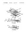
- FIG. 1is a perspective view of the illustrative embodiment of the automatic bar code symbol reading system of the present invention, showing the hand-supportable laser bar code symbol reading device supported within the scanner support stand for automatic hands-free operation;
- FIG. 1Ais an elevated front view of the automatic bar code symbol reading system of FIG. 1 , showing the light transmission window of the hand-supportable bar code symbol reading device while supported within the scanner support stand;
- FIG. 1Bis a plan view of the automatic bar code symbol reading system shown in FIG. 1 ;
- FIG. 1Cis a bottom view of the automatic bar code symbol reading system shown in FIG. 1 ;
- FIG. 2is a perspective view of the automatic hand-supportable bar code symbol reading device of the system hereof, shown being used in the automatic hands-on mode of operation;
- FIG. 2Ais a elevated, cross-sectional side view taken along the longitudinal extent of the automatic bar code symbol reading device of FIG. 2 , showing various hardware and software components utilized in realizing the illustrative embodiment of the automatic hand-supportable bar code symbol reading device of the present invention
- FIG. 2Bis a cross-sectional plan view taken along line 2 B— 2 B of FIG. 2A , showing the various components used in realizing the illustrative embodiment of the automatic bar code symbol reading device;
- FIG. 2Cis an elevated partially fragmented cross-sectional view of the head portion of the automatic hand-supportable bar code symbol reading device of the present invention, illustrating an electro-optical arrangement utilized in transmitting pulsed infrared light signals over the object detection field of the device;
- FIG. 2Dis an elevated partially fragmented cross-sectional view of the head portion of the automatic hand-supportable bar code symbol reading device of the present invention, illustrating the electro-optical arrangement utilized in producing the object detection field of the device;
- FIG. 3is an elevated side view of the hand-supportable bar code symbol reading device of the illustrative embodiment of the present invention, illustrating the spatial relationship between the object detection and scan fields of the device, and the long and short-ranges of programmed object detection, bar code presence detection, and bar code symbol reading;
- FIG. 3Ais a plan view of the automatic hand-supportable bar code symbol reading device taken along line 3 A— 3 A of FIG. 3 ;
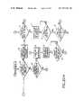
- FIG. 4is a system block functional diagram of the automatic hand-supportable bar code symbol reading device of the present invention, illustrating the principal components integrated with the system controller thereof;
- FIG. 5is a block functional diagram of a first embodiment of the object detection mechanism for the automatic hand-supportable bar code symbol reading device of the present invention
- FIG. 6is a block functional diagram of a second embodiment of the object detection mechanism for the automatic hand-supportable bar code symbol reading device of the present invention.
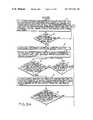
- FIGS. 7A and 7Btaken together, show a high level flow chart of a system control program (i.e. Main System Control Routine) contained within the control system of the automatic bar code symbol reading device, illustrating various courses of programmed system operation that the illustrative embodiment may undergo;
- a system control programi.e. Main System Control Routine
- FIGS. 8A and 8Btaken together, show a high level flow chart of an auxilliary system control program (i.e. Auxilliary System Control Routine with Range Selection), which provides the hand-supportable automatic bar code symbol reading device of the present invention with several selectable modes of object detection, bar code presence detection and bar code symbol reading;
- auxilliary system control programi.e. Auxilliary System Control Routine with Range Selection
- FIG. 9is a state diagram illustrating the various states that the automatic hand-supportable bar code symbol reading device of the illustrative embodiment may undergo during the course of its programmed operation;
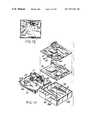
- FIG. 10is a perspective view of the support frame of the scanner support stand of the present invention.
- FIG. 10Ais a perspective view of the base plate of the scanner support stand of the present invention, with the adapter module mounted thereon;
- FIG. 10Bis a perspective, partially broken away view of the assembled scanner support stand of the present invention, showing the scanner cable, power supply cable and communication cable operably associated therewith and routed through respective apertures formed in the scanner support frame;
- FIGS. 11A through 11Dare perspective views of a point-of-sale system, showing the scanner support stand of the present invention supported on a horizontal countertop surface and operably connected to an electronic cash register, with the automatic hand-supportable bar code symbol reading device being used in its hand-held short-range mode of operation;
- FIGS. 12A and 12Bare perspective views illustrating the steps carried out during the installation of the scanner support stand of the present invention onto a vertical counter wall surface;
- FIG. 13is an elevated side view of the automatic bar code symbol reading system of the present invention, shown mounted onto the vertical counter wall surface of FIGS. 12A and 12B ;
- FIG. 13Ais a plan view of the automatic bar code symbol reading system of the present invention taken along line 13 A— 13 A of FIG. 13 ;
- FIG. 13Bis a cross-sectional view of the scanner support stand of the present invention, taken along line 13 B— 13 B of FIG. 13 ;
- FIG. 13Cis a cross-sectional view of the assembled scanner stand, taken along line 13 C— 13 C of FIG. 15A ;
- FIG. 14is perspective views showing the scanner support stand mounted on a vertical counter wall surface, and the automatic hand-supportable bar code symbol reading device being used in its automatic hands-free long-range mode of operation;
- FIGS. 15A and 15Bare perspective views showing the scanner support stand mounted on a vertical counter wall surface, and the automatic hand-supportable bar code symbol reading device being used in its automatic hand-held short-range mode of operation;
- FIG. 16is a perspective view of a point-of-sale station according to the present invention, showing the scanner support stand pivotally supported above a horizontal counter surface by way of a pedestal base mounted under an electronic cash register, and the automatic hand-supportable bar code symbol reading device received in the scanner support stand and being used in its automatic hands-free long-range mode of operation;
- FIGS. 17A and 17Bare perspective views of a point-of-sale station according to the present invention, showing the scanner support stand pivotally supported above a horizontal counter surface by way of the pedestal base illustrated in FIG. 16 , and the automatic hand-supportable bar code symbol reading device being used in its automatic hand-held short-range mode of operation;
- FIG. 18is an elevated side view of the point-of-sale system of FIGS. 16A , 16 B and 17 , illustrating the rotational freedom of the scanner support stand about the x axis of the pivotal joint assembly;
- FIG. 18Ais an elevated, partially cross-sectional view of the base plate of the scanner support stand and the pivotal joint assembly connecting the scanner support stand to the pedestal base so as to provide three-degrees of freedom to the scanner support stand with respect to the stationary pedestal base;
- FIG. 18Bis a partially fragmented view of the scanner support stand, pivotal joint assembly and pedestal base taken along the y axis of the pivotal joint assembly, illustrating the rotational freedom of the scanner support stand about the y axis;
- FIG. 18Cis a perspective view of the scanner support stand and pedestal base assembly taken along the -z axis of the pivotal joint assembly, illustrating the rotational freedom of the scanner support stand about the z axis of the pivotal joint assembly.
- automatic bar code symbol reading system 1comprises a portable, automatic hand-supportable bar code (symbol) reading device 2 operably associated with scanner support stand 3 of the present invention.
- Operable interconnection of hand-supportable bar code reading device 2 and scanner support stand 3is achieved by a flexible multiwire scanner cable 5 extending from bar code symbol device 2 into scanner support stand 3 .
- Operable interconnection of scanner support stand 3 and a host system 6is achieved by a flexible multiwire communications cable 7 extending from scanner-support stand 3 and plugged directly into the data-input communications port of host system 6 .
- electrical power from a low voltage power supply(not shown) is provided to scanner support stand 3 by way of a flexible power cable 8 .
- scanner support stand 3is particularly adapted for receiving and supporting hand-supportable bar code reading device 2 in a selected position without user support, thus providing a stationary, automatic hands-free mode of operation.
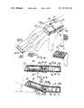
- hand-supportable bar code reading device 2includes an ultralight weight hand-supportable housing 9 having a contoured handle portion 9 A and a head portion 9 B.
- head portion 98encloses electro-optical components which are used to generate and project a visible laser beam through a light transmissive window 10 , and to repeatedly scan the projected laser beam across a scan field 11 defined external to the hand-supportable housing.
- scanner support stand 3includes a support frame 12 which comprises a base portion 12 A, a head portion support structure 12 B, handle portion support structure 12 C and a finger accommodating recess 12 D.
- base portion 12 Ahas a longitudinal extent and is adapted for selective positioning with respect to a support surface, e.g. countertop surface, counter wall surface, etc.
- Head portion support structure 12 Bis operably associated with base portion 12 A, for receiving and supporting the head portion of the hand-supportable bar code reading device.
- handle portion support structure 12 Cis operably associated with base portion 12 A, for receiving and supporting the handle portion of the hand-supportable bar code symbol reading device.
- finger accommodating recess 12 Dis disposed between head and handle portion support structures 12 B and 12 C and above base portion 12 A of the support frame.
- finger accommodating recess 12 Dis laterally accessible as shown in FIG. 13 so that when the handle and head portions 9 A and 9 B are received within and supported by handle portion support structure 12 B and head portion support structure 12 C, respectively, the fingers of a user's hand can be easily inserted through finger accommodating recess 12 D and completely encircle the handle portion of the hand-supportable device, as illustrated in FIG. 14 A.
- FIGS. 10 through 16BA more detailed description of the structure, functions and operation of the scanner support stand of the present invention will be provided hereinafter referring to FIGS. 10 through 16B .
- FIGS. 1 and 10 through 13attention will be first accorded to the illustrative embodiment of the automatic hand-supportable bar code reading device of the invention.
- head portion 98continuously extends into contoured handle portion 9 A at an obtuse angle a which, in the illustrative embodiment, is about 146 degrees. It is understood, however, that in other embodiments obtuse angle a may be in the range of about 135 to about 180 degrees. As this ergonomic housing design is sculpted (i.e. form-fitted) to the human hand, automatic hands-on scanning is rendered as easy and effortless as waving ones hand.
- this ergonomic housing designeliminates the risks of musculoskeletal disorders, such as carpal tunnel syndrome, which can result from repeated biomechanical stress commonly associated with pointing prior art gun-shaped scanners at bar code symbols, squeezing a trigger to activate the laser scanning beam, and then releasing the trigger.
- the head portion of housing 9has a transmission aperture 13 formed in upper portion of front panel 14 A, to permit visible laser light to exit and enter the housing, as will be described in greater detail hereinafter.
- the lower portion of front panel 14 Bis optically opaque, as are all other surfaces of the hand-supportable housing.
- automatic hand-supportable bar code reading device 2generates two different fields external to the hand-supportable housing, in order to carry out automatic bar code symbol reading according to the principles of the present invention.
- the first fieldreferred to as the “object detection field”, indicated by broken and dotted lines, is provided externally to the housing for detecting energy reflected off an object bearing a bar code symbol, located within the object detection field.
- the second fieldreferred to as the “scan field”, having at least one laser beam scanning plane is provided external to the housing for scanning a bar code symbol on an object in the object detection field.
- scanningis achieved with a visible laser beam which produces laser scan data which is collected for the purpose of detecting the presence of a bar code symbol within the scan field, and subsequently reading (i.e. scanning and decoding) the detected bar code symbol.
- detected energy reflected from an object during object detectioncan be optical radiation or acoustical energy, either sensible or non-sensible by the user, and may be either generated from the automatic bar code reading device or an external ambient source.
- the provision of such energyis preferably achieved by transmitting a wide beam of pulsed infrared light away from transmission aperture 13 and substantially parallel to longitudinal axis of the head portion of the hand-supportable housing.
- the object detection field, from which such reflected energy is collectedis designed to have a narrowly divirging pencil-like geometry of three-dimensional volumetric expanse, which is spatially coincident with at least a portion of the transmitted infrared light beam.
- This feature of the present inventionensures that an object residing within the object detection field will be illuminated by the infrared light beam, and that infrared light reflected therefrom will be directed generally towards the transmission aperture of the housing where it can be automatically detected to indicate the presence of the object within the object detection field.
- a visible laser beamis automatically generated within the head portion of the housing, projected through the transmission aperture and repeatedly scanned across the scan field, within which at least a portion of the detected object lies. At least a portion of the scanned laser light beam will be scattered and reflected off the object and directed back towards and through light transmissive window 10 for collection and detection within the head portion of the housing, and subsequently processed in a manner which will be described in detail hereinafter.
- the object detection fieldis designed to spatially encompass at least a portion of the scan field along the operative scanning range of the device, as illustrated in FIGS. 3 and 3A .
- This structural feature of the present inventionprovides the user with an increased degree of control, as once an object is detected, minimal time will be required by the user to point the visible laser beam towards the bar code symbol for scanning. In effect, the laser beam pointing efficiency of the device is markedly improved during the automatic bar code reading process, as it is significantly easier for the user to align the laser beam across the bar code symbol upon object detection.
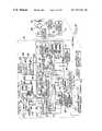
- automatic bar code reading device 2comprises a number of system components, namely, an object detection circuit 16 , laser scanning mechanism 17 , photoreceiving circuit 18 , analog-to-digital (A/D) conversion circuit 19 , bar code presence detection module 30 , bar code scan range detection module 21 , symbol decoding module 22 , data format conversion module 23 , symbol character data storage unit 24 , and data transmission circuit 25 .
- a magnetic field sensing circuit 26is provided for detecting scanner support stand 3
- a manual switch 27is provided for selecting long or short-range modes of object detection, bar code presence detection and/or bar code symbol reading, which will be described in great detail hereinafter.
- these componentsare operably associated with a programmable system controller 28 which provides a great degree of versatility in system control, capability and operation. The structure, function and advantages of this system controller will become apparent hereinafter.
- system controller 28bar code presence detection module 20 , bar code scan range detection module 21 , symbol decoding module 22 , and data format conversion module 23 are realized using a single programmable device, such as a microprocessor having accessible program and buffer memory, and external timing circuitry. It is understood, however, that any of these elements may be realized using separate discrete components as will be readily apparent to those with ordinary skill in the art.
- Automatic hand-supportable bar code reading device 2also includes power receiving lines 29 which lead to conventional power distribution circuitry (not shown) for providing requisite power to each of the system components, when and for time prescribed by the system controller. As illustrated, power receiving lines 29 run alongside data communication lines 30 and are physically associated with multi-pin connector plug 31 at the end of flexible scanner cable 5 . An on/off power switch or functionally equivalent device (not shown) may be provided external the hand-supportable housing to permit the user to selectively energize and deenergize the device. In the illustrative embodiment, power delivered through flexible scanner cable 5 to the bar code symbol reading device is continuously provided to system controller 28 so as to continuously enable its operation, while only biasing voltages and the like are provided to all other system components. In this way, each system component must be activated (i.e. enabled) by the system controller in accordance with its preprogrammed system control routine.
- the purpose of the object detection circuitis to determine whether an object (e.g., product, document, etc.) is present or absent from the object detection field over particular time intervals specified by the system controller.
- the system controllerwill respond to this event by causing the bar code reading device to undergo a transition from the object detection state to the bar code symbol (presence) detection state.
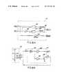
- FIGS. 5 and 6two different techniques are disclosed for detecting the presence of an object within the object detection field.
- an “active” object detection circuit 16 Ais shown. In essence, this circuit operates by transmitting a pulsed infrared (IR) light signal forwardly into the object detection field.
- First control activation signal A 1is generated upon receiving a reflection of the transmitted signal from an object residing within the object detection field.
- object defection circuit 16 Ais realized as an IR sensing circuit which comprises a synchronous receiver/transmitter 33 and an infrared LED 34 which generates a 940 nanometer pulsed signal at a rate of 15.0 KHZ. This pulsed IR signal is transmitted through focusing lens 35 to illuminate the object detection field.
- a reflected IR pulse signalis produced from the surface of the object, spatially filtered by aperture stop 65 B and focused through focusing lens 36 onto photodiode 37 .
- selection of the optical characteristics of aperture stop 65 B and lens 36 and (ii) the placement of photodiode 37 (with integrally formed lens 36 ) behind aperture stop 65 Bdirectly determine the geometric characteristics of the object detection field. Consequently, these optical parameters are selected so as to provide an object detection field which, as hereinbefore explained, spatially encompasses at least a portion of the scanning field along the operative scanning range of the device. As illustrated in FIG.
- a “passive” object detection circuit 10 Bis shown. In essence this circuit operates by passively detecting ambient light within the object detection field. First control activation signal A 1 is generated upon receiving light of different intensity reflected off an object within the object detection field.
- object detection circuit 16 Bis realized as a passive ambient light detection circuit which comprises a pair of photodiodes 39 and 40 , that sense ambient light gathered from two spatially overlapping parts of the object detection field using focussing lenses 41 and 42 , respectively.
- the optical characteristics of focusing lenses 41 and 42 and the placement of photodiodes 39 and 40 relative to lenses 41 and 42will collectively determine the geometric characteristics of the object detection field.
- optical parameterswill be selected to provide an object detection field which spatially encompasses at least a portion of the scanning field along the operative scanning range of the device.
- the output signals of photodiodes 39 and 40are converted to voltages by current-to-voltage amplifiers 43 and 44 respectively, and are provided as input to a differential amplifier 45 .
- the output of differential amplifier 45is provided as input to a sample and hold amplifier 46 in order to reject 60 Hz and 120 Hz noise.
- Output signal of amplifier 46is provided as input to a logarithmic amplifier 47 to compand signal swing.
- the output signal of logarithmic amplifier 47is provided as input to a differentiator 48 and then to a comparator 49 .
- the automatic bar code reading device of the present inventioncan be readily adapted to sense ultrasonic energy reflected off an object present within the object detection field.
- object detection circuit 16is realized as an ultrasonic energy transmitting/receiving mechanism.
- ultrasonic energyis generated and transmitted forwardly of the housing head portion into the object detection field.
- ultrasonic energy reflected off an object within the object detection fieldis detected closely adjacent the transmission window using an ultrasonic energy detector.
- a focusing elementis disposed in front of the detector in order to effectively maximize the collection of reflected ultrasonic energy.
- the focusing elementessentially determines the geometrical characteristics of the object detection field of the device. Consequently, as with the other above-described object detection circuits, the energy focusing (i.e. collecting) characteristics of the focusing element will be selected to provide an object detection field which spatially encompasses at least a portion of the scan field.
- the long-range specification for object detectionis preferrably preselected to be the full or entire range of sensitivity provided by IR sensing circuit 16 A (e.g. 0 to about 10 inches).
- the short-range of object detectionis about 0 to about 3 inches or so to provide CCD-like scanner emulation.
- the inherently limited depth and width of field associated with the short-range mode of object detectionprevents laser scanning mechanism 17 from flooding the scan field with laser scanning light and thus inadvertently detecting undesired bar code symbols.
- object detection range selectionwill be put, will be described in greater detail hereinafter with reference to FIGS. 11A through 16B in particular.
- laser scanning mechanism 17comprises a light source 50 which, in general, may be any source of intense light suitably selected for maximizing the reflectively from the object's surface bearing the bar code symbol.
- light source 50comprises a solid-state visible laser diode (VLD) which is driven by a conventional driver circuit 51 .
- VLDvisible laser diode
- the wavelength of visible laser light produced from the laser diodeis preferably about 670 nanometers.
- a planar scanning mirror 52is oscillated back and forth by a stepper motor 53 driven by a conventional driver circuit 54 .
- a conventional laser scanning mechanismsmay be alternatively used with excellent results.
- the system controllerprovides laser diode enable signal E L and scanning motor enable signal E M as input to driver circuits 51 and 54 , respectively.
- Photoreceiving circuit 18detects at least a portion of the reflected laser light of variable intensity. Upon detection of this reflected laser light, photoreceiving circuit 18 produces an analog scan data signal D 1 indicative of the detected light intensity.
- photoreceiving circuit 18generally comprises laser light collection optics 55 , which focus reflected laser light for subsequent detection by a photoreceiver 56 having, mounted in front of its sensor, a frequency selective filter 57 which only transmits optical radiation of wavelengths up to a small band above 670 nanometers.
- Photoreceiver 56produces an analog signal which is subsequently amplified by preamplifier 58 to produce analog scan data signal D 1 .
- laser scanning mechanism 17 and photoreceiving circuit 18cooperate to generate analog scan data signals D 1 from the scan field, over time intervals specified by the system controller. As will illustrated hereinafter, these scan data signals are used by bar code presence detection module 20 , bar code scan range detection module 21 , and symbol decoding module 22 to perform particular functions.
- analog scan data signal D 1is provided as input to A/D conversion circuit 19 .
- A/D conversion circuit 19processes analog scan data signal D 1 to provide a digital scan data signal D 2 which resembles, in form, a pulse width modulated signal, where logical “1” signal levels represent spaces of the scanned bar code and logical “0” signal levels represent bars of the scanned bar code.
- A/D conversion circuit 19can be realized by any conventional A/D circuit well known to those with ordinary skill in the art. Digitized scan data signal D 2 is then provided as input to bar code presence detection module 20 , bar code scan range detection module 21 and symbol decoding module 22 .
- bar code presence detection module 20is realized as a microcode program carried out by the microprocessor and associated program and buffer memory, described hereinbefore.
- the function of the bar code presence detection moduleis not to carry out a decoding process, but rather to rapidly determine whether the received scan data signals represent a bar code symbol residing within the scan field.
- bar code presence detection module 20detects the first and second borders of the bar code symbol “envelope”. This is achieved by first processing a digital scan data signal D 2 to produce digitial “count” and “sign” data.
- the digital count datais representative of the measured time interval (i.e. duration) of each signal level occurring between detected signal level transitions which occur in digitized scan data signal D 2 .
- the digital sign dataindicates whether the signal level between detected signal level transitions is either a logical “1”, representative of a space, or a logical “0”, representative of a bar within a bar code symbol.
- long-range specification for bar code presence detectionis preselected to be the entire operative scanning range available to the device. In an illustrated embodiment, this range can be from about 0 to about 10 inches from the transmission aperture, depending on the optics employed in the laser scanning mechanism and the response characteristics of the photoreceiving circuit. These long and short-range specifications are schematically indicated in FIGS. 3 and 3A .
- short-range specification for bar code presence detectionis preselected to be the same range selected for short-range object detection (e.g. approximately 0 to about 3 inches from the transmission aperture). As will become apparent hereinafter, the inherently limited depth and width of field associated with the short-range mode of bar code symbol detection, prevents the reading of detected bar code symbols residing outside the short-range portion of the scan field.
- bar code scan range detection module 21is not to detect the presence of a bar code symbol in the scan field, but rather to determine the range (i.e. distance) at which a detected or decoded bar code symbol resides from the light transmissive window of the housing.
- this data processing moduleoperates upon digital scan data signal D 2 which has been previously utilized by either the bar code symbol detection module, or the symbol decoding module depending on the state of the system.
- symbol decoding module 22the function of symbol decoding module 22 is to process, scan line by scan line, the stream of digitized scan data D 2 , in an attempt to decode a valid bar code symbol within a predetermined time period allowed by the system controller.
- symbol character data D 3typically in ASCII code format
- the symbol decoding moduleis provided with two different modes of detection, namely: a long-range mode and a short-range mode of bar code symbol decoding.
- the system controllerprovides enable signals E FC , E DS and E DT to data format conversion module 23 , data storage unit 24 and data transmission circuit 25 , respectively, at particular stages of its control program.
- symbol Lo decoding module 22provides symbol character data D 3 to data format module 23 to convert data D 3 into two differently formatted types of symbol character data, namely D 4 and D 5 .
- Format-converted symbol character data D 4is of the “packed data” format, particularly adapted for efficient storage in data storage unit 24 .
- Format-converted symbol character data D 5is particularly adapted for data transmission to host computer system 6 (e.g. an electronic cash register).
- the system controllerWhen symbol character data D 4 is to be converted into the format of the user's choice (based on a selected option mode), the system controller provides enable signal E DS to data storage unit 24 , as shown in FIG. 4 . Similarly, when format converted data D 5 is to be transmitted to host device 5 , the system controller provides enable signal E DT to data transmission circuit 25 . Thereupon, data transmission circuit 24 transmits format-converted symbol character data D 5 to host computer system 6 , via the data transmission lines of flexible scanner connector cable 5 .
- the hand-supportable bar code reading deviceis provided with both manual and automated mechanisms for effectuating such range selections.
- a manual switch 27is mounted on the top surface of the handle portion of the housing, so that long and short-range modes of object and bar code range detection can be selected by simply depressing this switch with ones thumb while handling the bar code reading device.
- magnetic sensing circuit 26comprises a magnetic flux detector 60 , a preamplifier and a threshold detection circuit.
- Magnetic flux detector 60produces as output an electrical signal representative of the intensity of detected magnetic flux density in its proximity.
- magnetic flux detector 60is in position to detect magnetic flux emanating from a magnetic bar fixedly mounted within the handle portion support structure of the scanner support stand.
- magnetic flux detector 60is mounted to the rearward underside surface of the handle portion of housing 9 .
- a ferrous bar 61is interiorly mounted to the underside surface of the housing handle portion as shown.
- this arrangementfacilitates releasable magnetic attachment of the hand-supportable housing to the magnetic bar fixedly installed in the handle portion support structure of the scanner support stand.
- a hole 61 Ais drilled through ferrous bar 61 to permit installation of magnetic flux detector 60 so that magnetic flux emanating from the handle portion support structure is detectable when the hand-supportable housing is placed within the scanner support stand, as shown in FIGS. 1 , 13 , 15 , and 17 .
- E IRTlong-range object detection
- a thin ferrous plate 62is exteriorly applied to the underside of the head portion of the hand-supportable housing.
- ferrous elements 61 and 62are to provide a means by which the plastic hand-supportable housing can be magnetically attracted by magnetic elements installed within head and handle portion support structures 12 B and 12 C when the bar code reading device is placed in the scanner support stand.
- FIGS. 2A through 2Done preferred arrangement is illustrated.
- FIG. 2Athe optical arrangement of the system components is shown. Specifically, visible laser diode 50 is mounted in the rear corner of circuit board 63 installed within the head portion of the housing. Stationary concave mirror 55 is mounted centrally at the front end of circuit board 63 , primarily for the purpose of collecting laser light reflected off detected objects. Notably, the height of concave mirror 55 is such as not to block transmission aperture 13 . Mounted off center onto the surface of concave mirror 55 , is a very small second mirror 64 for directing the laser beam to planar mirror 52 which is connected to the motor shaft of scanning motor 53 , for joint oscillatory movement therewith. As shown, scanning motor 53 is mounted centrally at the rear end of circuit board 63 . In the opposite rear corner of circuit board 63 , photodetector 56 and frequency selective filter 57 are mounted.
- laser diode 50 adjacent the rear of the head portionproduces a laser beam which is directed in a forward direction to the small stationary mirror 64 and is then reflected back to oscillating mirror 52 .
- Oscillating mirror 52directs the laser beam through transmission aperture 13 and light transmissive window 10 , while repeatedly scanning the laser beam across the scan field.
- the visible laser beamis aligned with a bar code symbol on the detected object, so that the laser beam scans the bar and space pattern thereof.
- a portion of the scattered laser light reflected from the bar code symbolis directed back through the light transmissive window and towards oscillating mirror 52 , which also acts as a light retroreflective mirror.
- Oscillating mirror 52then directs the reflected laser light to stationary concave collecting mirror 55 at the forward end of the head portion of the hand-supportable housing.
- the laser light collected from the concave mirror 55is then directed to photodetector 56 to produce an electrical signal representative of the detected intensity of the laser light reflected off the bar code symbol.
- IR LED 34 and photodiode 37are mounted to circuit board 63 , in front of stationary concave mirror 55 and in a slightly offset manner from longitudinal axis 15 of the head portion of the housing.
- Apertures 65 A and 65 Bare formed in opaque housing panel 14 B, below transmission aperture 13 , to permit transmission and reception of pulsed IR energy signals, as hereinbefore described.
- a metallic optical tube 66 having an aperture 67encases photodiode 37 . The dimensions of aperture 67 , the placement of IR LED 34 and its radiation transmission characteristics collectively will determine the radiation pattern of the transmitted IR signal from aperture 65 A in the housing.
- photodiode 37is located at a selected distance behind aperture stop 65 B formed in opaque housing panel 14 B, as shown in FIG. 2 D.
- light transmissive window 10is realized as a plastic filter lens 10 is installed over the transmission aperture.
- This plastic filter lenshas optical characteristics which transmit only optical radiation from slightly below 670 nanometers.
- circuit board 63carries all other electronic components and associated circuitry used in realizing IR object detection circuit 16 A, scanning mechanism 17 , photoreceiving circuit 18 , and A/D conversion 19 .
- a second circuit board 69is mounted within the handle portion of the housing, as shown in FIGS. 2A and 2B .
- the function of circuit board 69is to carry electronic components and associated circuitry used in realizing bar code presence detection module 20 , bar code scan range detection module 21 , symbol decoding module 22 , data format conversion module 23 , data storage unit 24 , data transmission circuit 25 , magnetic field detection circuit 26 , manual range/mode selection switch 27 , and system controller 28 .
- All conductors associated with flexible multiwire scanner cable 5are electrically connected to circuit board 69 in a manner well known in the art. Electrical communication between circuit boards 62 and 69 is realized using a plurality of electrical wires jumping across these circuit boards.
- bar code reading device 2is initialized. This involves activating (i.e. enabling) IR sensing circuit 16 A and the system controller.
- a preset time periode.g. O ⁇ T 1 , ⁇ 3 seconds
- the system controlleractivates laser diode 50 , scanning motor 53 , photoreceiving circuit 18 , A/D conversion circuit 19 and bar code presence detection module 20 in order to collect and analyze scan data signals D 2 for the purpose of determining whether or not a bar code is within the scan field.
- the system controllerdeactivates laser diode 50 , scanning motor 53 , photoreceiving circuit 18 , A/D conversion circuit 19 and bar code presence detection module 20 .
- Block Hthe system controller continues activation of laser diode 40 , scanning motor 53 , photoreceiving circuit 18 , and A/D conversion circuit 19 , while commencing activation of symbol decoding module 20 .
- the system controllerstarts timer T 3 to run for a time period O ⁇ T 3 ⁇ 1 second.
- this eventcauses a state transition from the bar code reading state to the object detection state.
- the system controllerreturns to the START block, as shown.
- control activation signal A 31 from symbol decoding module 29 , indicative that a bar code symbol has been successfully read
- the system controllerproceeds to Block O.
- the system controllercontinues to activate laser diode 50 , scanning motor 53 , photoreceiving circuit 18 and A/D conversion circuit 19 , while deactivating symbol decoding module 22 and commencing activation of data format conversion module 23 , data storage unit 24 and data transmission circuit 25 .
- the system controllerAfter transmission of symbol character data to the host device is completed, the system controller enters Block P and continues activation of laser diode 50 , scanning motor 53 , photoreceiving circuit 18 and A/D conversion circuit 19 , while deactivating symbol decoding module 22 , data format-conversion module 22 , data storage unit 24 and data transmission circuit 25 .
- the system controllerproceeds through Blocks W and X to reactivate the symbol decoding module and start timer T 6 to run for a time period O ⁇ T 6 ⁇ 1 second. These events represent a transition from the bar code symbol detection state to the bar code symbol reading state.
- the system controllerIf a bar code symbol is not successfully read within this 1 second time period, the system controller returns to Block T to form a first loop, within which the device is permitted to detect or redetect a bar code symbol within the time period O ⁇ T 6 ⁇ 5 seconds. If a bar code symbol is decoded within this time interval, the system controller determines at Block Z whether the decoded bar code symbol s different from the previously decoded bar code symbol. If at is different, then the system controller returns to Block O as illustrated, to format and transmit symbol character data as described hereinabove.
- Block AAthe system controller checks to determine whether timer T 6 has lapsed. If it has not lapsed, the system controller returns to Block T to form a second loop, within which the device is permitted to detect or redetect a bar code symbol in the scan field and then successfully read a valid bar code symbol within the set time interval O ⁇ T 6 ⁇ 5 seconds. If, however, timer T 6 lapses, then the system controller proceeds to Block BB at which the system controller deactivates laser diode 50 , scanning motor 53 , photoreceiving circuit 18 , A/D conversion circuit 19 , bar code presence detection module 20 , and symbol decoding module 22 .
- the system controllerreturns to the START block, as shown in FIG. 7 B.
- the operation of automatic hand-supportable bar code reading device 2has been described in connection with The Main System Control Routine which uses control activation signals A 1 , A 2 and A 3 .
- the bar code symbol reading devicemay not be desirable to automatically advance the bar code symbol reading device to its bar code presence detection state until an object bearing a bar code is within the short-range portion of the object detection field, as hereinbefore described. Also, it may not be desirable to automatically advance to the bar code symbol reading state until a detected bar code symbol is located within the short-range portion of the scan field. Also, it may not be desirable to automatically advance to the symbol character data storage/transmission state until a decoded bar code symbol is located within the short-range portion of the scan field.
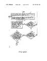
- FIGS. 8 A and BBillustrate The Auxilliary System Control Routine with Range Selection which provides the automatic tar code reading device of the present invention with range selection capabilities for object detection, bar code presence detection, and bar code symbol reading. These range selection functions are provided when the system controller runs the Auxilliary System Control Routine of in cooperation with the Main System Control Routine described above. It is understood, however, that this Auxilliary System Control Routine may be adapted for use with other suitable system control programs.
- the short-range modemay be selected by simply lifting the bar code reading device out from the scanner support stand, as illustrated in FIGS. 2 , 11 C, 14 B, and 16 B.
- the manual or automatic range mode selection mechanismbe programmably set within the system controller by way of bar code menu programming, a technique well known in the art.
- the Auxilliary System Control Routine of FIGS. 8A and 8Bwill be described using the automatic range mode selection mechanism provided by magnetic sensing circuit 26 .
- Block E′ of FIG. 8Awhenever the control flow is at Blocks D, I or R in the Main System Control Routine, the system controller activates bar code presence detection 20 module and bar code scan range detection module 21 . Thereafter, while at any one of these control blocks, the bar code scan range detection module processes scan data signals D 2 so as to produce digital count and sign data as hereinbefore described. As indicated at Block F′, an additional condition is placed on control Blocks E, K and T in the Main System Control Routine so that a transition from the bar code presence detection state to the bar code symbol reading state occurs only if (i) the object is detected in the short-range portion of the object detection field, and (ii) the bar code symbol is detected in the short-range portion of the scan field.
- the system controllercontinues activation of the laser diode 50 , scanning motor 53 , photoreceiving circuit 18 and A/D conversion circuit 19 , while commencing activation of symbol decoding circuit 22 .
- short and long-range mode capabilitiescan be automatically selected by reading bar code symbols. This can be achieved by programming symbol decoding module 22 to recognize predesignated bar code symbols which automatically activate and deactivate long-range and short-range modes of object detection, bar code presence detection, and/or bar code symbol reading. This mechanism for automatic range selection is highly advantageous in many applications, such as, for example, reading bar code menus, CCD scanner emulation and the like.
- an additional conditionis placed on control Blocks E, K and T in the Main System Control Routine. Specifically, a transition from the bar code presence detection state to the bar code symbol reading state occurs only if the detected bar code symbol resides in the short-range portion of the scan field. This condition is satisfied by the scan range detection module determining whether or not the digital count data of the detected bar code symbol falls within a prespecified short-range count interval. If this digital count data does not fall within the short-range count interval, then as indicated at Block R′, the system controller proceeds to control Blocks F, L or U, respectfully, in the Main System Control Routine, as indicated at Block K′.
- This eventis represented at Block S′ of FIG. 8B by the system controller continuing the activation of laser diode 50 , scanning motor 53 , photoreceiving circuit 18 , A/D conversion circuit 19 and bar code scan range detection module 20 , while deactivating bar code symbol detection module 21 and activating symbol decoding module 22 .
- Block X′the symbol decoding module determines whether the decoded code symbol is a short-range mode deactivation symbol. If the decoded bar code symbol is such a symbol, then as indicated at Block Y′, the system controller activates the long-range mode by letting IR sensing circuit 16 A operate at full sensitivity, while deactivating bar code scan range detection module. Thereafter, the system proceeds to Blocks K or T, respectively, in the Main System Control Routine.
- the system controlleractivates the long-range mode by letting the IR sensing circuit 16 A to operate at full sensitivity, while deactivating bar code scan range detection module 21 . Thereafter, the system proceeds to Blocks K or T, respectively, in the Main System Control Routine. If, however, the decoded bar code symbol is not a short-range mode deactivation symbol, then the system directly proceeds to Blocks K or T, respectively in the Main System Control Routine.
- FIG. 9provides a state transition diagram for the illustrative embodiment.
- the automatic hand-supportable bar code reading device of the present inventionhas four basic states of operation namely: object detection, bar code symbol presence detection, bar code symbol reading, and symbol character data transmission/storage. The nature of each of these states has been described above in great detail. These four states are schematically illustrated as A, B, C and D, respectively, in the state transition diagram of FIG. 9 . Notably, two “extensional states” have also been provided so that the automatic bar code reading device of the illustrative embodiment is capable of reading an infinite number of consecutively different bar code symbols on a particularly detected object (e.g. a product or apparently continuous surface) without returning to the object detection state.
- a particularly detected objecte.g. a product or apparently continuous surface
- extensional states of operationare indicated as E and F and represent oar code presence detection and bar code symbol reading operations, respectively. As described above, these operations are employed when attempting to automatically read one or more consecutively different bar codes symbols, that is, after a first bar code symbol has been successfully read utilizing operational states A through C.
- transitions between the various statesare indicated by directional arrows. Besides each set of directional arrows are transition conditions expressed in terms of control activation signals (e.g. A 1 , A 2 and A 3 ), and where appropriate, state time intervals (e.g. T 1 , T 2 , T 3 , T 4 , T 5 and T 6 ).
- control activation signalse.g. A 1 , A 2 and A 3
- state time intervalse.g. T 1 , T 2 , T 3 , T 4 , T 5 and T 6 .
- the state diagram of FIG. 9expresses most simply the four basic and two extensional operations occurring during the control flow within the system control program of FIGS. 7A and 7B .
- the control activation signals A 1 , A 2 and A 3 in FIG. 9indicate which events within the object detection and/or scan fields can operate to effect a state transition within the allotted time frame(s), where prescribed.
- FIGS. 10 through 10Bthe scanner support stand of the present invention will be described.
- scanner stand 3 of the illustrative embodimentcomprises support frame 12 releasably connected to a base support/mounting plate 70 by way of a snap fit fastening mechanism illustrated in FIG. 13 C.
- support frame 12is formed as an injection molded shell, in which handle portion support structure 12 B is realized by a first support recess 71 ; whereas head portion support structure 12 C is realized by a second support recess 72 .
- first support recess 71is disposed above base portion 12 A and inclined at a first acute angle B 1 with respect thereto
- second support recess 72is disposed above base portion 12 B and inclined at a second acute angle B 2 with respect thereto.
- first support recess 72is formed by a first substantially planar support surface 73 surrounded by the projection of opposing side walls 74 A and 74 B and rear wall 74 C, extending above planar support surface 73 in a perpendicular fashion.
- the function of support recess 71is to receive and support the handle portion of hand-supportable bar code reading device.
- second support recess 72is formed by a second substantially planar support surface 75 surrounded by the projection of opposing side walls 76 A and 76 B and front wall surface 76 C extending above planar support surface 75 in a perpendicular fashion.
- the function of support recess 72is to receive and support the head portion of hand-supportable bar code reading device 2 .
- rear wall 74 Chas a scanner cable aperture 77 which permits flexible scanner cable 5 to extend freely out beyond support recess 71 .
- front wall projection 76 Cis slightly lower than side wall projection 76 A and 76 B to ensure that pulsed IR energy is freely transmitted from and received by object detection circuit 16 A contained within head portion 9 A.
- this structural feature of the scanner support standensures that visible laser light is projected, scanned and collected through light transmissive window 10 without obstruction, i.e. when the automatic bar code reading device is operated in its automatic hands-free mode, shown in FIGS. 15 and 17 .
- first and second magnetic elements 77 and 78are permanently mounted to the Underside of planar support surfaces 73 and 75 , respectively, as illustrated in FIG. 10 B. With this arrangement, magnetic flux of constant intensity continuously emanates from support recesses 71 and 72 .
- ferrous element 61 in handle portion 9 Ais magnetically attracted to magnetic element 77
- ferrous element 62 on head portion 9 Bis magnetically attracted to magnetic element 78 .
- the magnetic force of attraction between these elementsis selected so that a desired degree of force is required to lift the automatic bar code reading device out of scanner support stand, while preventing accidental displacement of the device from the scanner support stand during use in the hands-free mode of operation.
- base support/mounting plate 70is formed as a thin planar structure having perimetrical dimensions substantially equal to the perimetrical dimensions of the base portion of support frame 12 .
- a pair of projections 79 and 80extend perpendicularly, as shown.
- Projections 79 and 80have horizontal flanges 79 A and 80 A, respectively, which are adapted to snap fit into horizontal grooves 81 and 82 , formed on the interior surfaces of front and rear walls 76 C and 74 C, as shown in FIGS. 10A , 10 B and 13 C.
- a pair of spaced apart mounting holes 83 A and 83 Bare provided.
- a set of four centrally disposed mounting holes 84 A, 84 B, 84 C and 84 Dare provided.
- a set of four rubber feet 85 A, 85 B, 85 C and 85 Dmay be adhesively applied to the underside corners of the base plate 70 .
- an adapter module 86is concealed within the interior volume 87 contained between the interior surface of base portion 12 A of the support frame and the upper surface of base plate 70 .
- adapter module 86is adhesively affixed to the central portion of the upper surface of base plate 70 , as illustrated in FIG. 10 A.
- Scanner connector 31 of flexible scanner cable 5is plugged into scanner jack 86 A of the adapter module, and the communication cable connector of flexible communication cable 7 is plugged into communication jack 86 B.
- the power supply connector from the DC power supply, cable 8is plugged into power supply jack 86 C, as shown.
- support frame 12is snapped onto base plate 70 , as hereinbefore described, flexible scanner cable 5 is routed through aperture 87 , and flexible communication and power supply cables 7 and 8 are routed through aperture 88 formed in the lower portion of rear wall 74 C of the support frame, as shown in FIG. 10 B.
- automatic bar code reading device 2requires one regulated DC supply voltage to mower the visible laser diode and other electronic and opto-electronic components mounted on circuit boards 63 and 69 .
- a 12V DC supply voltageis available at the point-of-sale station.
- a DC-to-DC voltage converteris incorporated into adapter module 86 .
- adapter module 86also provides a means for converting the voltage level of the flexible power supply cable to one or more required voltages to be utilized in the bar code reading device.
- the automatic bar code reading device of the present inventionhas been described in great detail. Thus, it is appropriate at this juncture to illustrate the automatic hands-on and hands-free modes of operation of the system while utilized in different mounting installations.
- FIGS. 11A through 11Da point-of-sale station is shown comprising an electronic cash register 6 operably connected to the automatic bar code reading system of the present invention by way of flexible communication cable 7 .
- Low voltage DC poweris provided to the system by way of flexible power supply cable 8 .
- scanner support stand 2includes rubber feet 85 A through 85 D and is supported on a horizontal countertop surface 90 . If necessary or desired in such mounting installations, base plate 70 may be weighted by affixing one or more dense mass elements to the upper surface of the base plate.
- FIGS. 12A and 12Bthe scanner support stand of the present invention is shown being installed on a vertical counter wall surface of a point-of-sale station having an electronic cash register 6 .
- a pair of spaced apart mounting screws 94 A and 94 Bare partially screwed into vertical counter wall surface 93 so that base plate 70 will be vertically arranged slightly below horizontal countertop surface 95 .
- mounting holes 83 A and 83 B and screws 94 A and 94 Bare passed through base plate 70 , and then the base plate is slid down slightly and screws 94 A and 94 B completely threaded into the vertical counter wall surface.
- support frame 12is snap fitted over the mounted base plate, as shown in FIG. 12B , to provide an installed automatic bar code reading system, as shown in FIG. 13 .
- the usergrasps the handle portion of the bar code reading device as illustrated in FIG. 15A , and lifts it out of the scanner support stand. Then the user brings object 91 into the short-range portion of the object detection field as illustrated in FIG. 15B , so as to automatically detect the object and scan bar code symbol 92 with the visible laser beam repeatedly moving across the scan field. After the bar code symbol has been successfully read and an audible and/or visible indication thereof produced, the bar code reading device is placed back into the scanner support stand, automatically inducing the system into its long-range hands-free mode of operation.
- FIGS. 16 through 17Ba point-of-sale station is shown comprising the automatic bar code reading system of the present invention operably connected to electronic cash register 6 by way of flexible communication and power supply cables 7 and 8 .
- scanner support stand 3is pivotally supported above a horizontal counter surface 96 by way of a pivotal joint assembly 97 connected to pedestal base 98 mounted under the electronic cash register.
- pivotal joint assembly 97comprises a ball structure 99 joined to a mounting plate 100 by an extension 101 .
- the pivotal joint assembly 97also comprises a semispherical recess 102 formed in the end of a cylindrical support post 103 . As shown in FIG. 18 ,
- a ball clamping element 104having a semispherical recess 105 and a bore 106 , is connected to the distal end portion of support post 103 by an adjustment screw 107 passing through bore 106 and threaded into a hole 108 in the distal end portion of the support post
- adjustment screw 107By rotating knob 109 attached to adjustment screw 107 , aligned semispherical recesses 102 and 105 can be sufficiently separated apart to receive and retain ball structure 99 .
- ball structure 99can be securely clasped within semispherical recesses 102 and 105 at any desired orientation by simply tightening adjustment screw 107 with several turns of knob 109 .
- mounting plate 100is fixedly connected to base plate 70 by bolts 110 A through 110 D threaded through holes 111 A through 111 D and 84 A through 84 D, respectively.
- the proximal end of support post 103is fixedly connected to the upper portion of pedestal base member 98 A, by screw 112 .
- pedestal base member 98 Bis mounted under electronic cash register 6 .
- scanner support stand 3can be adjustably positioned and locked into virtually any orientation in three-dimensional space, owing to the three principle degrees of freedom provided by the pivotal joint assembly. In FIGS. 16A , 18 , 18 B and 18 C, these degrees of freedom are illustrated with respect to the cartesian coordinate system shown embedded within the pivotal joint assembly of the pedestal-mounted scanner support stand.
- the systemis automatically induced into its long-range hands-free mode of operation.
- the bar code symbol 92is repeatedly scanned by the visible laser beam scanned across the scan field.
- the usersimply grasps the automatic bar code reading device and lifts it out of the scanner support stand, as illustrated in FIG. 17 A.
- the objectis automatically detected and bar code symbol 92 scanned by the visible laser beam repeatedly scanned across the scan field.
- the automatic bar code reading devicecan be placed back into the scanner support stand, automatically inducing the system into its long-range hands-free mode of operation.
- the automatic hand-supportable devicemay not incorporate within its housing, electronic circuitry for carrying out control, decoding other data processing functions; instead such electronic circuitry may be contained within a remote unit operably associated with the hand-supportable device by way of the flexible scanner cable.
- the hand-supportable devicewill function as an automatic hand-supportable laser scanner.
- the housingmay be adapted for hand-mounting.
- the automatic bar code reading device and scanner support stand of the present inventionprovides a fully automatic bar code reading system characterized by a automatic long-range hands-free and short-range hands-on mode of operation, high-speed symbol recognition, and versatility.
- the automatic hand-supportable bar code reading device of the present inventionhas been provided with a wide variety of complex decision-making operations, endowing the system with a level of intelligence hitherto unattained in the bar code symbol reading art. Within the spirit of the present invention, additional decision-making operations may be provided to further enhance the capabilities of the system.
Landscapes
- Physics & Mathematics (AREA)
- Engineering & Computer Science (AREA)
- Electromagnetism (AREA)
- General Physics & Mathematics (AREA)
- Theoretical Computer Science (AREA)
- General Health & Medical Sciences (AREA)
- Artificial Intelligence (AREA)
- Computer Vision & Pattern Recognition (AREA)
- Toxicology (AREA)
- Health & Medical Sciences (AREA)
- General Engineering & Computer Science (AREA)
- Optics & Photonics (AREA)
- Cash Registers Or Receiving Machines (AREA)
Abstract
Description
Claims (8)
Priority Applications (6)
| Application Number | Priority Date | Filing Date | Title |
|---|---|---|---|
| US09/346,859US7077327B1 (en) | 1990-09-17 | 1999-07-02 | System for reading bar code symbols using bar code readers having RF signal transmission links with base stations |
| US09/777,114US6347743B2 (en) | 1991-09-17 | 2001-02-05 | Method and apparatus for programming functional system parameters in optical bar code scanners |
| US09/785,410US6460769B1 (en) | 1991-09-17 | 2001-02-16 | System for reading bar code symbols using portable bar code symbol readers having one-way RF signal transmission links with base stations |
| US09/824,122US6688527B2 (en) | 1990-09-17 | 2001-04-02 | Bar code scanning system with wireless communication links |
| US10/213,383US6761317B1 (en) | 1991-09-17 | 2002-08-05 | Reading bar code symbols using readers having one-way RF signal transmission links with base stations |
| US10/638,344US7040540B2 (en) | 1990-09-17 | 2003-08-12 | Bar code scanning system with wireless communication links |
Applications Claiming Priority (7)
| Application Number | Priority Date | Filing Date | Title |
|---|---|---|---|
| US07/583,421US5260553A (en) | 1990-09-17 | 1990-09-17 | Automatic hand-supportable laser bar code symbol scanner and method of reading bar code symbols using the same |
| US07/761,123US5340971A (en) | 1990-09-17 | 1991-09-17 | Automatic bar code reading system having selectable long range and short range modes of operation |
| US82191792A | 1992-01-16 | 1992-01-16 | |
| US07/898,919US5340973A (en) | 1990-09-17 | 1992-06-12 | Automatic laser scanning system and method of reading bar code symbols using same |
| US08/292,237US5808285A (en) | 1990-09-17 | 1994-08-17 | Portable code symbol reading device with one-way wireless data packet transmission link to base unit employing condition-dependent acoustical signalling for data packet reception acknowledgement |
| US08/890,576US6015091A (en) | 1990-09-17 | 1997-07-09 | System for reading bar code symbols using portable bar code symbol readers having one-way RF signal transmission links with base stations |
| US09/346,859US7077327B1 (en) | 1990-09-17 | 1999-07-02 | System for reading bar code symbols using bar code readers having RF signal transmission links with base stations |
Related Parent Applications (3)
| Application Number | Title | Priority Date | Filing Date |
|---|---|---|---|
| US07/761,123Continuation-In-PartUS5340971A (en) | 1990-09-10 | 1991-09-17 | Automatic bar code reading system having selectable long range and short range modes of operation |
| US08/890,576ContinuationUS6015091A (en) | 1990-09-17 | 1997-07-09 | System for reading bar code symbols using portable bar code symbol readers having one-way RF signal transmission links with base stations |
| US08/890,576Continuation-In-PartUS6015091A (en) | 1990-09-17 | 1997-07-09 | System for reading bar code symbols using portable bar code symbol readers having one-way RF signal transmission links with base stations |
Related Child Applications (4)
| Application Number | Title | Priority Date | Filing Date |
|---|---|---|---|
| US38932095AContinuation-In-Part | 1991-09-17 | 1995-02-16 | |
| US09/777,114Continuation-In-PartUS6347743B2 (en) | 1991-09-17 | 2001-02-05 | Method and apparatus for programming functional system parameters in optical bar code scanners |
| US09/785,410ContinuationUS6460769B1 (en) | 1991-09-17 | 2001-02-16 | System for reading bar code symbols using portable bar code symbol readers having one-way RF signal transmission links with base stations |
| US09/824,122ContinuationUS6688527B2 (en) | 1990-09-17 | 2001-04-02 | Bar code scanning system with wireless communication links |
Publications (1)
| Publication Number | Publication Date |
|---|---|
| US7077327B1true US7077327B1 (en) | 2006-07-18 |
Family
ID=31192575
Family Applications (3)
| Application Number | Title | Priority Date | Filing Date |
|---|---|---|---|
| US09/346,859Expired - Fee RelatedUS7077327B1 (en) | 1990-09-17 | 1999-07-02 | System for reading bar code symbols using bar code readers having RF signal transmission links with base stations |
| US09/824,122Expired - Fee RelatedUS6688527B2 (en) | 1990-09-17 | 2001-04-02 | Bar code scanning system with wireless communication links |
| US10/638,344Expired - Fee RelatedUS7040540B2 (en) | 1990-09-17 | 2003-08-12 | Bar code scanning system with wireless communication links |
Family Applications After (2)
| Application Number | Title | Priority Date | Filing Date |
|---|---|---|---|
| US09/824,122Expired - Fee RelatedUS6688527B2 (en) | 1990-09-17 | 2001-04-02 | Bar code scanning system with wireless communication links |
| US10/638,344Expired - Fee RelatedUS7040540B2 (en) | 1990-09-17 | 2003-08-12 | Bar code scanning system with wireless communication links |
Country Status (1)
| Country | Link |
|---|---|
| US (3) | US7077327B1 (en) |
Cited By (18)
| Publication number | Priority date | Publication date | Assignee | Title |
|---|---|---|---|---|
| US20040232243A1 (en)* | 2003-04-07 | 2004-11-25 | Silverbrook Research Pty Ltd | Laser scanner using acousto-optic deflectors |
| US20050103860A1 (en)* | 2003-11-13 | 2005-05-19 | Xiaoxun Zhu | Digital imaging-based bar code symbol reading system employing an led-based multi-mode illumination subsystem with far-field and near-field led illumination arrays driven by an automatic light exposure measurement and illumination control subsystem responsive to control activation signals generated by an automatic object presence and range detection subsystem |
| US20050269409A1 (en)* | 2004-06-04 | 2005-12-08 | Perner Fredrick A | Magnetic stripline scanner |
| US7347374B2 (en) | 2003-11-13 | 2008-03-25 | Metrologic Instruments, Inc. | Hand-supportable digital imaging-based bar code symbol reader employing an event-driven system control subsystem, automatic IR-based object detection, and trigger-switch activated image capture and processing subsystem |
| US20080172303A1 (en)* | 2007-01-17 | 2008-07-17 | Ole-Petter Skaaksrud | Internet-based shipping, tracking and delivery network and system components supporting the capture of shipping document images and recognition-processing thereof initiated from the point of pickup and completed while shipment is being transported to its first scanning point in the network so as to increase velocity of shipping information through network and reduce delivery time |
| US20080283611A1 (en)* | 2000-11-24 | 2008-11-20 | Metrologic Instruments, Inc. | Digital image capture and processing systems for supporting 3D imaging volumes in retail point-of-sale environments |
| US20080283608A1 (en)* | 2003-11-13 | 2008-11-20 | Metrologic Instruments, Inc. | Method of illuminating objects on a countertop surface using an automatically-triggered digital image capture and processing system which maintains illumination rays substantially within the field of view (FOV) of said system, above which the field of view (FOV) of human operator and spectating customers are positioned |
| US7464877B2 (en) | 2003-11-13 | 2008-12-16 | Metrologic Instruments, Inc. | Digital imaging-based bar code symbol reading system employing image cropping pattern generator and automatic cropped image processor |
| US7513428B2 (en) | 2001-11-21 | 2009-04-07 | Metrologic Instruments, Inc. | Planar laser illumination and imaging device employing laser current modulation to generate spectral components and reduce temporal coherence of laser beam, so as to achieve a reduction in speckle-pattern noise during time-averaged detection of images of objects illuminated thereby during imaging operations |
| US7516898B2 (en) | 2000-11-24 | 2009-04-14 | Metrologic Instruments, Inc. | Digital image capturing and processing system for producing and projecting a complex of coplanar illumination and imaging planes into a 3D imaging volume and controlling illumination control parameters in said system using the detected motion and velocity of object |
| US7523863B2 (en) | 1999-06-07 | 2009-04-28 | Metrologic Instruments, Inc. | Hand-supportable LED-based planar illumination and imaging system |
| US7527202B2 (en) | 2000-06-07 | 2009-05-05 | Metrologic Instruments, Inc. | Hand-supportable planar linear illumination and imaging (PLIIM) based code symbol reading system |
| US7527200B2 (en) | 1998-03-24 | 2009-05-05 | Metrologic Instruments, Inc. | Planar laser illumination and imaging (PLIIM) systems with integrated despeckling mechanisms provided therein |
| US7594609B2 (en) | 2003-11-13 | 2009-09-29 | Metrologic Instruments, Inc. | Automatic digital video image capture and processing system supporting image-processing based code symbol reading during a pass-through mode of system operation at a retail point of sale (POS) station |
| US7607581B2 (en) | 2003-11-13 | 2009-10-27 | Metrologic Instruments, Inc. | Digital imaging-based code symbol reading system permitting modification of system features and functionalities |
| US7708205B2 (en) | 2003-11-13 | 2010-05-04 | Metrologic Instruments, Inc. | Digital image capture and processing system employing multi-layer software-based system architecture permitting modification and/or extension of system features and functions by way of third party code plug-ins |
| US8371506B2 (en) | 2011-01-26 | 2013-02-12 | Koamtac, Inc. | Handheld barcode code input device with no-power supplied switch trigger |
| US8517273B2 (en) | 2010-05-28 | 2013-08-27 | Datalogic ADC, Inc. | Data reader with multiple modes of operation |
Families Citing this family (57)
| Publication number | Priority date | Publication date | Assignee | Title |
|---|---|---|---|---|
| DE69920969T2 (en)* | 1998-12-03 | 2005-10-20 | Metrologic Instruments Inc. | Automatically activated, portable laser bar code scanner with data transfer device |
| US20020125323A1 (en)* | 2001-03-06 | 2002-09-12 | Welch Allyn Data Collection, Inc. | Optical scanner data collection network employing multi-packet transmission of decoded data |
| US7797374B2 (en)* | 2001-04-17 | 2010-09-14 | Cbs Interactive Inc. | System and method for providing digital messaging services |
| TW534533U (en)* | 2001-12-12 | 2003-05-21 | Lite On It Corp | LCD monitor having power switching function |
| US6726099B2 (en)* | 2002-09-05 | 2004-04-27 | Honeywell International Inc. | RFID tag having multiple transceivers |
| US20060108421A1 (en)* | 2003-12-03 | 2006-05-25 | Becker Robert C | RFID tag having multiple transceivers |
| US7250845B2 (en)* | 2004-01-16 | 2007-07-31 | Two Technologies, Inc. | Radio frequency identification device with movable antenna |
| US8316068B2 (en) | 2004-06-04 | 2012-11-20 | Telefonaktiebolaget Lm Ericsson (Publ) | Memory compression |
| US7442085B2 (en)* | 2005-01-14 | 2008-10-28 | Molex Incorporated | Filter connector |
| US7021548B1 (en)* | 2005-02-09 | 2006-04-04 | Rocca Jason A | Photosensor cover and kit |
| US7556203B2 (en) | 2005-06-27 | 2009-07-07 | Hand Held Products, Inc. | Method and system for linking a wireless hand held optical reader with a base unit or other wireless device |
| WO2007028008A2 (en)* | 2005-08-31 | 2007-03-08 | Two Technologies, Inc. | Systems for integrating peripheral devices with hand-held computing devices |
| US8478386B2 (en) | 2006-01-10 | 2013-07-02 | Accuvein Inc. | Practitioner-mounted micro vein enhancer |
| US10238294B2 (en) | 2006-06-29 | 2019-03-26 | Accuvein, Inc. | Scanned laser vein contrast enhancer using one laser |
| US8489178B2 (en) | 2006-06-29 | 2013-07-16 | Accuvein Inc. | Enhanced laser vein contrast enhancer with projection of analyzed vein data |
| US9492117B2 (en) | 2006-01-10 | 2016-11-15 | Accuvein, Inc. | Practitioner-mounted micro vein enhancer |
| US8838210B2 (en) | 2006-06-29 | 2014-09-16 | AccuView, Inc. | Scanned laser vein contrast enhancer using a single laser |
| US9854977B2 (en) | 2006-01-10 | 2018-01-02 | Accuvein, Inc. | Scanned laser vein contrast enhancer using a single laser, and modulation circuitry |
| US10813588B2 (en) | 2006-01-10 | 2020-10-27 | Accuvein, Inc. | Micro vein enhancer |
| US8255040B2 (en) | 2006-06-29 | 2012-08-28 | Accuvein, Llc | Micro vein enhancer |
| US12408865B2 (en) | 2006-01-10 | 2025-09-09 | Accuvein Inc. | Vein imaging device with differential image resolution at the center and the extremities of the vein image |
| US11278240B2 (en) | 2006-01-10 | 2022-03-22 | Accuvein, Inc. | Trigger-actuated laser vein contrast enhancer |
| US12295744B2 (en) | 2006-01-10 | 2025-05-13 | Accuvein, Inc. | Micro vein enhancer with two lasers and two optical detectors configured for removing surface topology |
| US11253198B2 (en) | 2006-01-10 | 2022-02-22 | Accuvein, Inc. | Stand-mounted scanned laser vein contrast enhancer |
| US12089951B2 (en) | 2006-01-10 | 2024-09-17 | AccuVeiw, Inc. | Scanned laser vein contrast enhancer with scanning correlated to target distance |
| US7686216B2 (en) | 2006-06-13 | 2010-03-30 | Hand Held Products, Inc. | Method and apparatus for uniquely associating a bar code reading terminal to a cash register in a retail store network |
| US8730321B2 (en) | 2007-06-28 | 2014-05-20 | Accuvein, Inc. | Automatic alignment of a contrast enhancement system |
| US8463364B2 (en) | 2009-07-22 | 2013-06-11 | Accuvein Inc. | Vein scanner |
| US8594770B2 (en) | 2006-06-29 | 2013-11-26 | Accuvein, Inc. | Multispectral detection and presentation of an object's characteristics |
| US7733659B2 (en)* | 2006-08-18 | 2010-06-08 | Delphi Technologies, Inc. | Lightweight audio system for automotive applications and method |
| FR2912821B1 (en)* | 2007-02-20 | 2009-05-08 | Somfy Soc Par Actions Simplifi | METHOD FOR CONFIGURING A DOMOTIC INSTALLATION AND TOOL FOR IMPLEMENTING SUCH A METHOD |
| US7706140B2 (en)* | 2007-10-04 | 2010-04-27 | Hands Held Products, Inc. | Portable data terminal internal support structure |
| EP2297671B1 (en)* | 2008-05-28 | 2016-10-19 | Datalogic IP TECH S.r.l. | Recharge cradle for a coded information reader and reading system comprising it |
| CN102047269B (en)* | 2008-05-28 | 2015-07-22 | 得利捷扫描集团有限公司 | Bracket for coded information reader and reading system comprising the same |
| US9166975B2 (en) | 2012-02-16 | 2015-10-20 | Inbay Technologies Inc. | System and method for secure remote access to a service on a server computer |
| US9608988B2 (en)* | 2009-02-03 | 2017-03-28 | Inbay Technologies Inc. | Method and system for authorizing secure electronic transactions using a security device having a quick response code scanner |
| US9548978B2 (en) | 2009-02-03 | 2017-01-17 | Inbay Technologies Inc. | Method and system for authorizing secure electronic transactions using a security device |
| US9485254B2 (en) | 2009-02-03 | 2016-11-01 | Inbay Technologies Inc. | Method and system for authenticating a security device |
| US9521142B2 (en) | 2009-02-03 | 2016-12-13 | Inbay Technologies Inc. | System and method for generating passwords using key inputs and contextual inputs |
| US8973111B2 (en)* | 2009-02-03 | 2015-03-03 | Inbay Technologies Inc. | Method and system for securing electronic transactions |
| US8739252B2 (en) | 2009-02-03 | 2014-05-27 | Inbay Technologies Inc. | System and method for secure remote access |
| US9736149B2 (en) | 2009-02-03 | 2017-08-15 | Inbay Technologies Inc. | Method and system for establishing trusted communication using a security device |
| US9061109B2 (en) | 2009-07-22 | 2015-06-23 | Accuvein, Inc. | Vein scanner with user interface |
| JP5358370B2 (en)* | 2009-09-18 | 2013-12-04 | 株式会社キーエンス | Optical information reader |
| US8186592B2 (en)* | 2009-12-07 | 2012-05-29 | Hand Held Products, Inc. | Universal stand for indicia readers |
| FI124722B (en)* | 2011-03-24 | 2014-12-31 | Nordic Id Oy | Device comprising a reader and method for controlling the function of the reader |
| US9072426B2 (en) | 2012-08-02 | 2015-07-07 | AccuVein, Inc | Device for detecting and illuminating vasculature using an FPGA |
| USD716818S1 (en) | 2012-09-26 | 2014-11-04 | Datalogic Ip Tech S.R.L. | Cradle for mobile terminals |
| US10517483B2 (en) | 2012-12-05 | 2019-12-31 | Accuvein, Inc. | System for detecting fluorescence and projecting a representative image |
| EP2943920B1 (en)* | 2013-01-13 | 2019-12-11 | Retail Technologies Corporation | Mobile bar code scanner gun system with mobile tablet device having a mobile pos |
| USD730357S1 (en)* | 2013-07-03 | 2015-05-26 | Hand Held Products, Inc. | Scanner |
| JP2015060296A (en)* | 2013-09-17 | 2015-03-30 | 船井電機株式会社 | Spatial coordinate specification device |
| USD790546S1 (en)* | 2014-12-15 | 2017-06-27 | Hand Held Products, Inc. | Indicia reading device |
| US10817689B2 (en)* | 2017-12-21 | 2020-10-27 | Datalogic IP Tech, S.r.l. | Systems and methods for a scan engine coupled to a finger mount |
| US10803270B2 (en)* | 2018-12-07 | 2020-10-13 | Zebra Technologies Corporation | Scan cube characteristics |
| CN113193882B (en)* | 2021-04-02 | 2023-07-14 | 渝丰科技股份有限公司 | Power carrier communication-based field help-seeking positioning method |
| GB2637498A (en)* | 2024-01-23 | 2025-07-30 | Falcona Solutions Ltd | Handheld barcode scanning module and associated method |
Citations (27)
| Publication number | Priority date | Publication date | Assignee | Title |
|---|---|---|---|---|
| US3793636A (en) | 1972-01-28 | 1974-02-19 | Moog Inc | Nonconductive data link control apparatus |
| US3806131A (en) | 1972-03-29 | 1974-04-23 | Athletic Swing Measurement | Swing measurement and display system for athletic implements |
| US3826900A (en) | 1972-10-13 | 1974-07-30 | Ncr | Cordless scanning probe |
| US3953798A (en) | 1973-11-09 | 1976-04-27 | U.S. Philips Corporation | Method and device for radio transmission of binary data signals |
| US3991389A (en) | 1974-09-18 | 1976-11-09 | International Business Machines Corporation | Digital frequency shift key modulator |
| US4005388A (en) | 1973-11-21 | 1977-01-25 | Termiflex Corporation | Hand-held interactive terminal |
| US4016532A (en) | 1975-11-05 | 1977-04-05 | Rose Levi L | Emergency traffic control system with security transmission coding |
| US4090135A (en) | 1976-06-29 | 1978-05-16 | The United States Of America As Represented By The Secretary Of The Interior | Wireless FSK technique for telemetering underground data to the surface |
| US4115662A (en) | 1975-06-06 | 1978-09-19 | Etablissement Public Dit Telediffusion De France | One way data transmission system |
| US4184116A (en) | 1977-04-07 | 1980-01-15 | Argos Products Company, Inc. | Communication system having analog-to-digital-to-analog conversion means |
| US4232299A (en) | 1978-08-02 | 1980-11-04 | The Singer Company | Wireless output/input system |
| US4247908A (en) | 1978-12-08 | 1981-01-27 | Motorola, Inc. | Re-linked portable data terminal controller system |
| US4415065A (en) | 1980-11-17 | 1983-11-15 | Sandstedt Gary O | Restaurant or retail vending facility |
| US4418277A (en) | 1980-11-19 | 1983-11-29 | Hartmut Tremmel | Apparatus for collecting, transmitting and processing data stored in code, preferably in bar code |
| US4460120A (en) | 1982-01-25 | 1984-07-17 | Symbol Technologies, Inc. | Narrow bodied, single- and twin-windowed portable laser scanning head for reading bar code symbols |
| US4588881A (en) | 1982-07-12 | 1986-05-13 | Privates Institut Fur Physikalisch Technische Auftragsforschung Gmbh | System for monitoring the movements of goods inwards and/or outwards |
| US4672658A (en) | 1985-10-16 | 1987-06-09 | At&T Company And At&T Bell Laboratories | Spread spectrum wireless PBX |
| US4751500A (en) | 1987-02-10 | 1988-06-14 | Knogo Corporation | Detection of unauthorized removal of theft detection target devices |
| US4789983A (en) | 1987-03-05 | 1988-12-06 | American Telephone And Telegraph Company, At&T Bell Laboratories | Wireless network for wideband indoor communications |
| US4829540A (en) | 1986-05-27 | 1989-05-09 | Fairchild Weston Systems, Inc. | Secure communication system for multiple remote units |
| US4850009A (en) | 1986-05-12 | 1989-07-18 | Clinicom Incorporated | Portable handheld terminal including optical bar code reader and electromagnetic transceiver means for interactive wireless communication with a base communications station |
| US4870391A (en) | 1988-04-05 | 1989-09-26 | Knogo Corporation | Multiple frequency theft detection system |
| US4897532A (en)* | 1985-02-28 | 1990-01-30 | Symbol Technologies, Inc. | Portable laser diode scanning head |
| US4916441A (en) | 1988-09-19 | 1990-04-10 | Clinicom Incorporated | Portable handheld terminal |
| US5029183A (en) | 1989-06-29 | 1991-07-02 | Symbol Technologies, Inc. | Packet data communication network |
| JPH03174681A (en)* | 1989-08-21 | 1991-07-29 | Ncr Corp | Hand optical scanner |
| US5189291A (en) | 1989-05-01 | 1993-02-23 | Symbol Technologies, Inc. | Bar code reader operable as remote scanner or with fixed terminal |
Family Cites Families (87)
| Publication number | Priority date | Publication date | Assignee | Title |
|---|---|---|---|---|
| US3978317A (en) | 1974-02-26 | 1976-08-31 | Matsushita Electric Industrial Co., Ltd. | Optical bar code reader |
| US3925639A (en) | 1974-03-25 | 1975-12-09 | Msi Data Corp | Method and apparatus for reading bar coded data wherein a light source is periodically energized |
| US3911270A (en) | 1974-08-28 | 1975-10-07 | Identicon Corp | Light pen reading |
| US3961198A (en)* | 1975-04-28 | 1976-06-01 | Rockwell International Corporation | Visually alignable sensor wand which excludes unwanted light from a sensor system |
| US4086476A (en) | 1976-07-29 | 1978-04-25 | Ncr Corporation | Control circuit for a code reading device |
| JPS5330223A (en) | 1976-09-01 | 1978-03-22 | Nippon Denso Co Ltd | Automaitc code reading unit |
| US4118687A (en) | 1976-10-04 | 1978-10-03 | Recognition Equipment Incorporated | Portable OCR system |
| US4160156A (en) | 1978-05-04 | 1979-07-03 | Msi Data Corporation | Method and apparatus for reading bar coded data wherein the light source is periodically energized |
| US4251798A (en)* | 1978-05-31 | 1981-02-17 | Symbol Technologies | Portable laser scanning arrangement for and method of evaluating and validating bar code symbols |
| US4240064A (en) | 1978-09-11 | 1980-12-16 | Ncr Corporation | Power limiting circuit for bar code reader |
| US4496831A (en) | 1980-02-29 | 1985-01-29 | Symbol Technologies, Inc. | Portable laser scanning system and scanning methods |
| US4387297B1 (en) | 1980-02-29 | 1995-09-12 | Symbol Technologies Inc | Portable laser scanning system and scanning methods |
| US4431912A (en) | 1981-11-13 | 1984-02-14 | International Business Machines Corp. | Method for controlling the operation of an optical scanner |
| US4570057A (en) | 1981-12-28 | 1986-02-11 | Norand Corporation | Instant portable bar code reader |
| US4673805A (en) | 1982-01-25 | 1987-06-16 | Symbol Technologies, Inc. | Narrow-bodied, single- and twin-windowed portable scanning head for reading bar code symbols |
| US4736095A (en) | 1982-01-25 | 1988-04-05 | Symbol Technologies, Inc. | Narrow-bodied, single- and twin-windowed portable laser scanning head for reading bar code symbols |
| US5180904A (en) | 1982-01-25 | 1993-01-19 | Symbol Technologies, Inc. | Bar code scanner with automatic de-activation of scan upon bar code recognition |
| US4409470A (en) | 1982-01-25 | 1983-10-11 | Symbol Technologies, Inc. | Narrow-bodied, single-and twin-windowed portable laser scanning head for reading bar code symbols |
| US5017765A (en) | 1982-01-25 | 1991-05-21 | Symbol Technologies, Inc. | Hand held bar code scanner with automatic scanner deenergization |
| US4603262A (en)* | 1983-08-22 | 1986-07-29 | Optel Systems Inc. | Optical device for detecting coded symbols |
| US4575625A (en)* | 1983-09-27 | 1986-03-11 | Knowles Carl H | Integral hand-held laser scanner |
| US4521678A (en) | 1984-01-13 | 1985-06-04 | Databar Corporation | Battery-powered optical bar code reader and voltage regulator therefor |
| US4639606A (en) | 1984-10-26 | 1987-01-27 | Optel System Limited | Bar code scanner laser radiation exposure limit control system |
| DE3687127T2 (en)* | 1985-02-28 | 1993-05-06 | Symbol Technologies Inc | PORTABLE SCAN HEAD WITH A LASER DIODE. |
| JPS62129663U (en)* | 1986-02-05 | 1987-08-17 | ||
| US4766299A (en) | 1986-03-28 | 1988-08-23 | Spectra-Physics, Inc. | Hand-mounted bar code reader |
| US4841132A (en) | 1986-07-21 | 1989-06-20 | Matsushita Electric Industrial Co., Ltd. | Program recording scheduling apparatus using an optical reader |
| US4877949A (en)* | 1986-08-08 | 1989-10-31 | Norand Corporation | Hand-held instant bar code reader system with automated focus based on distance measurements |
| US5949056A (en)* | 1986-09-10 | 1999-09-07 | Norand Corporation | Method and apparatus for optically reading an information pattern |
| US4845349A (en) | 1986-09-30 | 1989-07-04 | Spectra-Physics, Inc. | Bar code scanner laser emission reduction |
| US5457629A (en)* | 1989-01-31 | 1995-10-10 | Norand Corporation | Vehicle data system with common supply of data and power to vehicle devices |
| US4766297A (en) | 1987-01-08 | 1988-08-23 | Recognition Equipment Incorporated | Dual mode stationary and portable scanning system |
| US4876660A (en)* | 1987-03-20 | 1989-10-24 | Bipolar Integrated Technology, Inc. | Fixed-point multiplier-accumulator architecture |
| US4970379A (en) | 1987-04-30 | 1990-11-13 | Norand Corporation | Bar code scanner system and scanner circuitry therefor |
| US4793812A (en)* | 1987-10-05 | 1988-12-27 | Xerox Corporation | Hand held optical scanner for omni-font character recognition |
| US5479002A (en)* | 1988-05-11 | 1995-12-26 | Symbol Technologies, Inc. | Bar code scanner with scanning beam and/or field of view adjustable about three mutually orthogonal axes |
| US5412193A (en)* | 1988-05-11 | 1995-05-02 | Symbol Technologies, Inc. | Mobile point-of-sale supermarket checkout system |
| US5250790A (en) | 1988-05-11 | 1993-10-05 | Symbol Technologies, Inc. | Hand-mounted scanner with automatic manual initiation of reading indicia |
| US5216231A (en) | 1988-05-13 | 1993-06-01 | Alps Electric Co., Ltd. | Self-scanning code reading device |
| JPH0789328B2 (en)* | 1988-05-31 | 1995-09-27 | 日本電気株式会社 | Data processing device |
| USD305885S (en) | 1988-06-24 | 1990-02-06 | Symbol Technologies, Inc. | Hand-held optical scanner |
| US4933538A (en) | 1988-10-21 | 1990-06-12 | Symbol Technologies, Inc. | Scanning system with adjustable light output and/or scanning angle |
| US5086215A (en) | 1988-10-26 | 1992-02-04 | National Computer Systems, Inc. | Method and apparatus for discriminating or locating bar codes for an optical mark reader |
| US5107100A (en) | 1988-11-17 | 1992-04-21 | Symbol Technologies, Inc. | Portable scanner with on-board keyboard, display, transceiver and printer |
| USD307894S (en) | 1988-12-14 | 1990-05-15 | Symbol Technologies, Inc. | Hand-held laser scanner |
| US4930848A (en) | 1989-01-26 | 1990-06-05 | Metrologic Instruments, Inc. | Portable laser scanner with integral scanner engine |
| US5216233A (en)* | 1989-03-09 | 1993-06-01 | Norand Corporation | Versatile RF terminal-scanner system |
| JPH0546113Y2 (en) | 1989-03-20 | 1993-12-01 | ||
| US5539193A (en)* | 1989-06-07 | 1996-07-23 | Norand Corporation | Modular hand-held data entry system |
| US6053413A (en)* | 1989-06-16 | 2000-04-25 | Symbol Technologies, Inc. | Optical scanner with hand-held and hands-free modes of use |
| US5157687A (en)* | 1989-06-29 | 1992-10-20 | Symbol Technologies, Inc. | Packet data communication network |
| US5668803A (en)* | 1989-06-29 | 1997-09-16 | Symbol Technologies, Inc. | Protocol for packet data communication system |
| US5280498A (en)* | 1989-06-29 | 1994-01-18 | Symbol Technologies, Inc. | Packet data communication system |
| US5142131A (en) | 1989-08-21 | 1992-08-25 | Ncr Corporation | Hand-held bar code reader |
| US5053413A (en)* | 1989-09-05 | 1991-10-01 | G. D. Searle & Co. | N-benzylpiperidineisoindolinones |
| US5059777A (en) | 1989-09-21 | 1991-10-22 | Ncr Corporation | Scanning system presence sensing apparatus and method |
| US5691528A (en)* | 1989-10-30 | 1997-11-25 | Symbol Technologies Inc. | Scanning system for either hand-held or stationary operation for reading 1-D or 2-D barcodes |
| US5404001A (en) | 1992-10-08 | 1995-04-04 | Bard; Simon | Fiber optic barcode reader |
| JP2733357B2 (en) | 1990-02-09 | 1998-03-30 | 松下電器産業株式会社 | Barcode reader and barcode reading method |
| JPH03266195A (en) | 1990-03-16 | 1991-11-27 | Nec Corp | Vertical fixed scanner |
| US5808285A (en) | 1990-09-17 | 1998-09-15 | Metrologic Instruments, Inc. | Portable code symbol reading device with one-way wireless data packet transmission link to base unit employing condition-dependent acoustical signalling for data packet reception acknowledgement |
| US5340973A (en) | 1990-09-17 | 1994-08-23 | Metrologic Instruments, Inc. | Automatic laser scanning system and method of reading bar code symbols using same |
| US20030019938A1 (en)* | 1990-09-10 | 2003-01-30 | Metrologic Instruments, Inc. | Counter-top scanner with bump protection mechanism and scan angle adjustment mechanism |
| US5340971A (en) | 1990-09-17 | 1994-08-23 | Metrologic Instruments, Inc. | Automatic bar code reading system having selectable long range and short range modes of operation |
| US6412699B1 (en)* | 1990-09-11 | 2002-07-02 | Metrologic Instruments, Inc. | Method of and system for producing transaction-enabling graphical user interfaces at internet-enabled terminals in response to reading bar code symbols pointing to html-encoded documents embedded with java-applets and stored on http information servers |
| US6015091A (en)* | 1990-09-17 | 2000-01-18 | Metrologic Instruments, Inc. | System for reading bar code symbols using portable bar code symbol readers having one-way RF signal transmission links with base stations |
| US5979766A (en)* | 1990-09-17 | 1999-11-09 | Metrologic Instruments, Inc. | Bar code symbol reading system having one-way RF signal-receiving keyboard wedge interface |
| US5880452A (en)* | 1990-11-15 | 1999-03-09 | Geo Labs, Inc. | Laser based PCMCIA data collection system with automatic triggering for portable applications and method of use |
| US5148009A (en) | 1990-12-10 | 1992-09-15 | Ncr Corporation | Bar code scanning apparatus |
| US5132523A (en) | 1990-12-10 | 1992-07-21 | Ncr Corporation | Dual mode optical scanning system |
| US5105070A (en) | 1990-12-10 | 1992-04-14 | Ncr Corporation | Bar code scanning apparatus with rotating housing member |
| US5237161A (en) | 1991-06-05 | 1993-08-17 | Psc, Inc. | System for automatically reading symbols, such as bar codes, on objects which are placed in the detection zone of a symbol reading unit, such as a bar code scanner |
| US5434102A (en)* | 1991-02-25 | 1995-07-18 | Symetrix Corporation | Process for fabricating layered superlattice materials and making electronic devices including same |
| US5210398A (en) | 1991-06-14 | 1993-05-11 | Symbol Technologies, Inc. | Optical scanner with extended depth of focus |
| US5361871A (en)* | 1991-08-20 | 1994-11-08 | Digicomp Research Corporation | Product information system for shoppers |
| US6460769B1 (en)* | 1991-09-17 | 2002-10-08 | Metrologic Instruments, Inc. | System for reading bar code symbols using portable bar code symbol readers having one-way RF signal transmission links with base stations |
| US6761317B1 (en)* | 1991-09-17 | 2004-07-13 | Metrologic Instruments, Inc. | Reading bar code symbols using readers having one-way RF signal transmission links with base stations |
| US5607187A (en)* | 1991-10-09 | 1997-03-04 | Kiwisoft Programs Limited | Method of identifying a plurality of labels having data fields within a machine readable border |
| US5214270A (en) | 1991-11-22 | 1993-05-25 | Spectra-Physics | Modular handheld or fixed scanner |
| US6105871A (en)* | 1992-07-16 | 2000-08-22 | Telxon Corporation | Portable bar code scanner apparatus |
| US5334821A (en) | 1992-07-16 | 1994-08-02 | Telxon Corporation | Portable point of sale terminal |
| US5378860A (en)* | 1992-09-21 | 1995-01-03 | Dingfelder; Heinz | System and method for the prevention of theft in salesrooms |
| US5329106A (en) | 1992-10-02 | 1994-07-12 | Psc, Inc. | Handle-less bar code scanning system |
| US6832724B2 (en)* | 1993-03-26 | 2004-12-21 | Symbol Technologies, Inc. | Electro-optical assembly for image projection, especially in portable instruments |
| US5412699A (en)* | 1993-12-07 | 1995-05-02 | Niagara Mohawk Power Corporation | Brake tool for transversing incore probe |
| US5664231A (en)* | 1994-04-29 | 1997-09-02 | Tps Electronics | PCMCIA interface card for coupling input devices such as barcode scanning engines to personal digital assistants and palmtop computers |
| US5925292A (en)* | 1997-06-02 | 1999-07-20 | Aqua Life Corporation | Water charging machine |
- 1999
- 1999-07-02USUS09/346,859patent/US7077327B1/ennot_activeExpired - Fee Related
- 2001
- 2001-04-02USUS09/824,122patent/US6688527B2/ennot_activeExpired - Fee Related
- 2003
- 2003-08-12USUS10/638,344patent/US7040540B2/ennot_activeExpired - Fee Related
Patent Citations (27)
| Publication number | Priority date | Publication date | Assignee | Title |
|---|---|---|---|---|
| US3793636A (en) | 1972-01-28 | 1974-02-19 | Moog Inc | Nonconductive data link control apparatus |
| US3806131A (en) | 1972-03-29 | 1974-04-23 | Athletic Swing Measurement | Swing measurement and display system for athletic implements |
| US3826900A (en) | 1972-10-13 | 1974-07-30 | Ncr | Cordless scanning probe |
| US3953798A (en) | 1973-11-09 | 1976-04-27 | U.S. Philips Corporation | Method and device for radio transmission of binary data signals |
| US4005388A (en) | 1973-11-21 | 1977-01-25 | Termiflex Corporation | Hand-held interactive terminal |
| US3991389A (en) | 1974-09-18 | 1976-11-09 | International Business Machines Corporation | Digital frequency shift key modulator |
| US4115662A (en) | 1975-06-06 | 1978-09-19 | Etablissement Public Dit Telediffusion De France | One way data transmission system |
| US4016532A (en) | 1975-11-05 | 1977-04-05 | Rose Levi L | Emergency traffic control system with security transmission coding |
| US4090135A (en) | 1976-06-29 | 1978-05-16 | The United States Of America As Represented By The Secretary Of The Interior | Wireless FSK technique for telemetering underground data to the surface |
| US4184116A (en) | 1977-04-07 | 1980-01-15 | Argos Products Company, Inc. | Communication system having analog-to-digital-to-analog conversion means |
| US4232299A (en) | 1978-08-02 | 1980-11-04 | The Singer Company | Wireless output/input system |
| US4247908A (en) | 1978-12-08 | 1981-01-27 | Motorola, Inc. | Re-linked portable data terminal controller system |
| US4415065A (en) | 1980-11-17 | 1983-11-15 | Sandstedt Gary O | Restaurant or retail vending facility |
| US4418277A (en) | 1980-11-19 | 1983-11-29 | Hartmut Tremmel | Apparatus for collecting, transmitting and processing data stored in code, preferably in bar code |
| US4460120A (en) | 1982-01-25 | 1984-07-17 | Symbol Technologies, Inc. | Narrow bodied, single- and twin-windowed portable laser scanning head for reading bar code symbols |
| US4588881A (en) | 1982-07-12 | 1986-05-13 | Privates Institut Fur Physikalisch Technische Auftragsforschung Gmbh | System for monitoring the movements of goods inwards and/or outwards |
| US4897532A (en)* | 1985-02-28 | 1990-01-30 | Symbol Technologies, Inc. | Portable laser diode scanning head |
| US4672658A (en) | 1985-10-16 | 1987-06-09 | At&T Company And At&T Bell Laboratories | Spread spectrum wireless PBX |
| US4850009A (en) | 1986-05-12 | 1989-07-18 | Clinicom Incorporated | Portable handheld terminal including optical bar code reader and electromagnetic transceiver means for interactive wireless communication with a base communications station |
| US4829540A (en) | 1986-05-27 | 1989-05-09 | Fairchild Weston Systems, Inc. | Secure communication system for multiple remote units |
| US4751500A (en) | 1987-02-10 | 1988-06-14 | Knogo Corporation | Detection of unauthorized removal of theft detection target devices |
| US4789983A (en) | 1987-03-05 | 1988-12-06 | American Telephone And Telegraph Company, At&T Bell Laboratories | Wireless network for wideband indoor communications |
| US4870391A (en) | 1988-04-05 | 1989-09-26 | Knogo Corporation | Multiple frequency theft detection system |
| US4916441A (en) | 1988-09-19 | 1990-04-10 | Clinicom Incorporated | Portable handheld terminal |
| US5189291A (en) | 1989-05-01 | 1993-02-23 | Symbol Technologies, Inc. | Bar code reader operable as remote scanner or with fixed terminal |
| US5029183A (en) | 1989-06-29 | 1991-07-02 | Symbol Technologies, Inc. | Packet data communication network |
| JPH03174681A (en)* | 1989-08-21 | 1991-07-29 | Ncr Corp | Hand optical scanner |
Cited By (159)
| Publication number | Priority date | Publication date | Assignee | Title |
|---|---|---|---|---|
| US7527200B2 (en) | 1998-03-24 | 2009-05-05 | Metrologic Instruments, Inc. | Planar laser illumination and imaging (PLIIM) systems with integrated despeckling mechanisms provided therein |
| US7644866B2 (en) | 1999-06-07 | 2010-01-12 | Metrologic Instruments, Inc. | Hand-supportable code symbol reader employing coplanar laser illumination and linear imaging |
| US7533821B2 (en) | 1999-06-07 | 2009-05-19 | Metrologic Instruments, Inc. | Hand-supportable planar laser illumination and imaging (PLIIM) device for producing a planar laser illumination beam (PLIB) coplanar with the field of view (FOV) of a linear image detection array |
| US7523863B2 (en) | 1999-06-07 | 2009-04-28 | Metrologic Instruments, Inc. | Hand-supportable LED-based planar illumination and imaging system |
| US7621455B2 (en) | 1999-06-07 | 2009-11-24 | Metrologic Instruments, Inc. | Hand-supportable code symbol reader employing coplanar laser illumination and linear imaging |
| US7527202B2 (en) | 2000-06-07 | 2009-05-05 | Metrologic Instruments, Inc. | Hand-supportable planar linear illumination and imaging (PLIIM) based code symbol reading system |
| US7594608B2 (en) | 2000-11-24 | 2009-09-29 | Metrologic Instruments, Inc. | Automatic omnidirectional bar code symbol reading system employing linear-type and area-type bar code symbol reading stations within the system housing |
| US7581680B2 (en) | 2000-11-24 | 2009-09-01 | Metrologic Instruments, Inc. | Omni-directional digital image capturing and processing system employing coplanar illumination and imaging stations in horizontal and vertical housing sections of the system |
| US7806335B2 (en) | 2000-11-24 | 2010-10-05 | Metrologic Instruments, Inc. | Digital image capturing and processing system for automatically recognizing objects in a POS environment |
| US7793841B2 (en) | 2000-11-24 | 2010-09-14 | Metrologic Instruments, Inc. | Laser illumination beam generation system employing despeckling of the laser beam using high-frequency modulation of the laser diode current and optical multiplexing of the component laser beams |
| US7784695B2 (en) | 2000-11-24 | 2010-08-31 | Metrologic Instruments, Inc. | Planar laser illumination module (PLIM) employing high-frequency modulation (HFM) of the laser drive currents and optical multplexing of the output laser beams |
| US7775436B2 (en) | 2000-11-24 | 2010-08-17 | Metrologic Instruments, Inc. | Method of driving a plurality of visible and invisible LEDs so as to produce an illumination beam having a dynamically managed ratio of visible to invisible (IR) spectral energy/power during object illumination and imaging operations |
| US7770796B2 (en) | 2000-11-24 | 2010-08-10 | Metrologic Instruments, Inc. | Device for producing a laser beam of reduced coherency using high-frequency modulation of the laser diode current and optical multiplexing of the output laser beam |
| US7762465B2 (en) | 2000-11-24 | 2010-07-27 | Metrologic Instruments, Inc. | Device for optically multiplexing a laser beam |
| US7731091B2 (en) | 2000-11-24 | 2010-06-08 | Metrologic Instruments, Inc. | Digital image capturing and processing system employing automatic object detection and spectral-mixing based illumination techniques |
| US7673802B2 (en) | 2000-11-24 | 2010-03-09 | Metrologic Instruments, Inc. | Automatic POS-based digital image capturing and processing system employing a plurality of area-type illumination and imaging zones intersecting within the 3D imaging volume of the system |
| US7665665B2 (en) | 2000-11-24 | 2010-02-23 | Metrologic Instruments, Inc. | Digital illumination and imaging subsystem employing despeckling mechanism employing high-frequency modulation of laser diode drive current and optical beam multiplexing techniques |
| US7661597B2 (en) | 2000-11-24 | 2010-02-16 | Metrologic Instruments, Inc. | Coplanar laser illumination and imaging subsystem employing spectral-mixing and despeckling of laser illumination |
| US20080283611A1 (en)* | 2000-11-24 | 2008-11-20 | Metrologic Instruments, Inc. | Digital image capture and processing systems for supporting 3D imaging volumes in retail point-of-sale environments |
| US7661595B2 (en) | 2000-11-24 | 2010-02-16 | Metrologic Instruments, Inc. | Digital image capturing and processing system employing a plurality of area-type illuminating and imaging stations projecting a plurality of coextensive area-type illumination and imaging zones into a 3D imaging volume, and controlling operations therewithin using |
| US7658330B2 (en) | 2000-11-24 | 2010-02-09 | Metrologic Instruments, Inc. | Automatic POS-based digital image capturing and processing system employing object motion controlled area-type illumination and imaging operations |
| US7651028B2 (en) | 2000-11-24 | 2010-01-26 | Metrologic Instruments, Inc. | Intelligent system for automatically recognizing objects at a point of sale (POS) station by omni-directional imaging of the objects using a complex of coplanar illumination and imaging subsystems |
| US7815113B2 (en) | 2000-11-24 | 2010-10-19 | Metrologic Instruments, Inc. | Method of and system for returning a consumer product in a retail environment so as to prevent or reduce employee theft, as well as provide greater accountability for returned merchandise in retail store environments |
| US7819326B2 (en) | 2000-11-24 | 2010-10-26 | Metrologic Instruments, Inc. | Network of digital image capturing systems installed at retail POS-based stations and serviced by a remote image processing server in communication therewith |
| US7614560B2 (en) | 2000-11-24 | 2009-11-10 | Metrologic Instruments, Inc. | Method of illuminating objects at a point of sale (POS) station by adaptively controlling the spectral composition of the wide-area illumination beam produced from an illumination subsystem within an automatic digital image capture and processing system |
| US7611062B2 (en) | 2000-11-24 | 2009-11-03 | Metrologic Instruments, Inc. | Omni-directional digital image capturing and processing system employing coplanar illumination and imaging planes and area-type illumination and imaging zones with the horizontal and vertical sections of the system housing |
| US7546952B2 (en) | 2000-11-24 | 2009-06-16 | Metrologic Instruments, Inc. | Method of illuminating objects during digital image capture operations by mixing visible and invisible spectral illumination energy at point of sale (POS) environments |
| US7588188B2 (en) | 2000-11-24 | 2009-09-15 | Metrologic Instruments, Inc. | Pos-based digital image capturing and processing system using automatic object detection, spectral-mixing based illumination and linear imaging techniques |
| US7584892B2 (en) | 2000-11-24 | 2009-09-08 | Metrologic Instruments, Inc. | Digital-imaging based code symbol reading system employing a plurality of coplanar illumination and imaging subsystems, each having a local object motion detection subsystem for automatic detecting objects within the 3D imaging volume, and a local control subsystem for transmitting object detection state data to a global control subsystem for managing the state of operation of said coplanar illumination and imaging subsystems |
| US7806336B2 (en) | 2000-11-24 | 2010-10-05 | Metrologic Instruments, Inc. | Laser beam generation system employing a laser diode and high-frequency modulation circuitry mounted on a flexible circuit |
| US7578442B2 (en) | 2000-11-24 | 2009-08-25 | Metrologic Instruments, Inc. | Method of and apparatus for identifying consumer products in a retail environment when bar code symbols on the products are not readable or have been removed from packaging |
| US7578445B2 (en) | 2000-11-24 | 2009-08-25 | Metrologic Instruments, Inc. | Automatic POS-based digital image capturing and processing system employing object motion controlled area-type illumination and imaging operations |
| US7575169B2 (en) | 2000-11-24 | 2009-08-18 | Metrologic Instruments, Inc. | Digital image capturing and processing system for producing and projecting a plurality of coextensive area-type illumination and imaging zones into a 3D imaging volume and controlling illumination control parameters in said system using the detected motion of objects present therewithin |
| US7575170B2 (en) | 2000-11-24 | 2009-08-18 | Metrologic Instruments, Inc. | POS-based digital image capturing and processing system using automatic object detection, spectral-mixing based illumination and linear imaging techniques |
| US7571859B2 (en) | 2000-11-24 | 2009-08-11 | Metrologic Instruments, Inc. | Digital-imaging based code symbol reading system employing a plurality of coplanar illumination and imaging subsystems, global object motion detection subsystem for automatically detecting objects within its 3D imaging volume, and global control subsystem for managing the state of operation of said coplanar illumination and imaging substems |
| US7571858B2 (en) | 2000-11-24 | 2009-08-11 | Metrologic Instruemtns, Inc. | POS-based digital image capturing and processing system using automatic object detection, spectral-mixing based illumination and linear imaging techniques |
| US7568626B2 (en) | 2000-11-24 | 2009-08-04 | Metrologic Instruments, Inc. | Automatic POS-based digital image capturing and processing system employing a plurality of area-type illumination and imaging zones intersecting within the 3D imaging volume of the system |
| US7543749B2 (en) | 2000-11-24 | 2009-06-09 | Metrologic Instruments, Inc. | Digital image capturing and processing system having a plurality of coplanar illumination and imaging subsystems, each employing a dual-type coplanar linear illumination and imaging engine that supports image-processing based object motion and velocity detection, and automatic image formation and detection along the coplanar illumination and imaging plane produced thereby |
| US7516898B2 (en) | 2000-11-24 | 2009-04-14 | Metrologic Instruments, Inc. | Digital image capturing and processing system for producing and projecting a complex of coplanar illumination and imaging planes into a 3D imaging volume and controlling illumination control parameters in said system using the detected motion and velocity of object |
| US7520433B2 (en) | 2000-11-24 | 2009-04-21 | Metrologic Instruments, Inc. | Method for intelligently controlling the illumination and imagine of objects as they are moved through the 3D imaging volume of a digital image capturing and processing system |
| US7878407B2 (en) | 2000-11-24 | 2011-02-01 | Metrologic Instruments, Inc. | POS-based digital image capturing and processing system employing automatic object motion detection and spectral-mixing based illumination techniques |
| US7559474B2 (en) | 2000-11-24 | 2009-07-14 | Metrologic Instruments, Inc. | Automatic omnidirectional bar code symbol reading system employing linear-type and area-type bar code symbol reading stations within the system housing |
| US7905413B2 (en) | 2000-11-24 | 2011-03-15 | Metrologic Instruments, Inc. | Digital image capturing and processing system employing a plurality of coplanar illumination and imaging subsystems for digitally imaging objects in a 3D imaging volume, and a globally-deployed object motion detection subsystem for automatically detecting and analyzing the motion of objects passing through said 3-D imaging volume |
| US7527204B2 (en) | 2000-11-24 | 2009-05-05 | Metrologic Instruments, Inc. | Omni-directional digital image capturing and processing system comprising coplanar illumination and imaging stations automatically detecting object motion and velocity and adjusting exposure and/or illumination control parameters therewithin |
| US8042740B2 (en) | 2000-11-24 | 2011-10-25 | Metrologic Instruments, Inc. | Method of reading bar code symbols on objects at a point-of-sale station by passing said objects through a complex of stationary coplanar illumination and imaging planes projected into a 3D imaging volume |
| US7530497B2 (en) | 2000-11-24 | 2009-05-12 | Metrologic Instruments, Inc. | Digital image capturing and processing system employing an image capturing and processing module and an integrated electronic weigh scale module having a load cell centrally located with respect to said image capturing and processing module |
| US8172141B2 (en) | 2000-11-24 | 2012-05-08 | Metrologic Instruments, Inc. | Laser beam despeckling devices |
| US7533823B2 (en) | 2000-11-24 | 2009-05-19 | Metrologic Instruments, Inc. | Digital image capturing and processing system employing a plurality of coplanar illuminating and imaging stations projecting a plurality of coplanar illumination and imaging planes into a 3D imaging volume, and controlling operations therewithin using control data derived from motion data collected from the automated detection of objects passing through said 3D imaging volume |
| US7533820B2 (en) | 2000-11-24 | 2009-05-19 | Metrologic Instruments, Inc. | Digital image capturing and processing system employing coplanar illumination and imaging stations which generate coplanar illumination and imaging planes only when and where an object is being moved within the 3D imaging volume |
| US7537165B2 (en) | 2000-11-24 | 2009-05-26 | Metrologic Instruments, Inc. | Omni-directional digital image capturing and processing system employing coplanar illumination and imaging planes and area-type illumination and imaging zones within the system housing |
| US7540422B2 (en) | 2000-11-24 | 2009-06-02 | Metrologic Instruments, Inc. | Digital image capturing and processing system employing imaging window protection plate having an aperture pattern and being disposed over said imaging window and beneath which resides a plurality of coplanar illumination and imaging stations |
| US7556199B2 (en) | 2000-11-24 | 2009-07-07 | Metrologic Instruments, Inc. | Digital image capturing and processing system employing a plurality of coplanar illuminating and imaging stations projecting a complex of coplanar illumination and imaging planes into a 3D imaging volume so as to support pass-through and presentation modes of digital imaging at a point of sale (POS) environment |
| US7540424B2 (en) | 2000-11-24 | 2009-06-02 | Metrologic Instruments, Inc. | Compact bar code symbol reading system employing a complex of coplanar illumination and imaging stations for omni-directional imaging of objects within a 3D imaging volume |
| US7513428B2 (en) | 2001-11-21 | 2009-04-07 | Metrologic Instruments, Inc. | Planar laser illumination and imaging device employing laser current modulation to generate spectral components and reduce temporal coherence of laser beam, so as to achieve a reduction in speckle-pattern noise during time-averaged detection of images of objects illuminated thereby during imaging operations |
| US7612923B2 (en) | 2003-04-07 | 2009-11-03 | Silverbrook Research Pty Ltd | Scanning device for scanning interface surface of product item |
| US20090032599A1 (en)* | 2003-04-07 | 2009-02-05 | Silverbrook Research Pty Ltd | Scanner for scanning items marked with near-infrared tags |
| US8284461B2 (en) | 2003-04-07 | 2012-10-09 | Silverbrook Research Pty Ltd | Scanner for scanning items marked with tags |
| US7961360B2 (en) | 2003-04-07 | 2011-06-14 | Silverbrook Research Pty Ltd | Scanning device for scanning interface surface |
| US20100238521A1 (en)* | 2003-04-07 | 2010-09-23 | Silverbrook Research Pty Ltd | Scanner for scanning items marked with tags |
| US7702187B2 (en) | 2003-04-07 | 2010-04-20 | Silverbrook Research Pty Ltd | Scanner for scanning items marked with near-infrared tags |
| US7450273B2 (en)* | 2003-04-07 | 2008-11-11 | Silverbrook Research Pty Ltd | Laser scanner using acousto-optic deflectors |
| US7457007B2 (en)* | 2003-04-07 | 2008-11-25 | Silverbrook Research Pty Ltd | Laser scanning device for printed product identification codes |
| US20040232243A1 (en)* | 2003-04-07 | 2004-11-25 | Silverbrook Research Pty Ltd | Laser scanner using acousto-optic deflectors |
| US20090014526A1 (en)* | 2003-04-07 | 2009-01-15 | Silverbrook Research Pty Ltd | Scanning device for scanning interface surface of product item |
| US7950583B2 (en) | 2003-11-13 | 2011-05-31 | Metrologic Instruments, Inc | Automatic digital video imaging based code symbol reading system employing an automatic object motion controlled illumination subsystem |
| US7637432B2 (en) | 2003-11-13 | 2009-12-29 | Metrologic Instruments, Inc. | Automatic point-of-sale based code symbol reading system employing automatic object motion detection and illumination control, and digital video image capturing and processing techniques |
| US7575167B2 (en) | 2003-11-13 | 2009-08-18 | Metrologic Instruments, Inc. | Method of dynamically managing system control parameters in a digital image capture and processing system |
| US7490778B2 (en) | 2003-11-13 | 2009-02-17 | Metrologic Instruments, Inc. | Method of reading code symbols using a hand-supportable digital image capturing and processing device employing a micro-computing platform supporting an event-driven multi-tier modular software architecture |
| US7490774B2 (en) | 2003-11-13 | 2009-02-17 | Metrologic Instruments, Inc. | Hand-supportable imaging based bar code symbol reader employing automatic light exposure measurement and illumination control subsystem integrated therein |
| US7487917B2 (en) | 2003-11-13 | 2009-02-10 | Metrologic Instruments, Inc. | Automatic digital-imaging based code symbol reading system supporting pass-through and presentation modes of system operation using automatic object direction detection, narrow-area and wide-area illumination control, and narrow-area and wide-area video image capture and processing techniques |
| US7503499B2 (en) | 2003-11-13 | 2009-03-17 | Metrologic Instruments, Inc. | Digital image capturing and processing system producing narrow-band illumination when image sensor elements in a state of integration, and simultaneously detecting narrow-band illumination using an area-type image sensor and independently-operated photo-detector |
| US7484666B2 (en) | 2003-11-13 | 2009-02-03 | Metrologic Instruments, Inc. | Automatic digital-imaging based bar code symbol reading system supporting pass-through and presentation modes of system operation using automatic object direction detection and illumination control, and video image capture and processing techniques |
| US7588190B2 (en) | 2003-11-13 | 2009-09-15 | Metrologic Instruments, Inc. | Digital-imaging code symbol reading system supporting automatic programming of system parameters for automatic configuration of said system in hands-on and hands-free modes of operation |
| US7503498B2 (en) | 2003-11-13 | 2009-03-17 | Metrologic Instruments, Inc. | Hand-supportable digital image capturing and processing system employing an area-type image sensing array exposed to illumination from an LED-based illumination array only when all sensor elements in said image-sensing array are activated and in a state of integration |
| US7594609B2 (en) | 2003-11-13 | 2009-09-29 | Metrologic Instruments, Inc. | Automatic digital video image capture and processing system supporting image-processing based code symbol reading during a pass-through mode of system operation at a retail point of sale (POS) station |
| US7604175B2 (en) | 2003-11-13 | 2009-10-20 | Metrologic Instruments, Inc. | Method of reading bar code symbols using a digital-imaging based code symbol reading system employing an event-driven multi-tier modular software architecture and supporting automatic operating system login and loading of bar code symbol reading application |
| US7607581B2 (en) | 2003-11-13 | 2009-10-27 | Metrologic Instruments, Inc. | Digital imaging-based code symbol reading system permitting modification of system features and functionalities |
| US7469835B2 (en) | 2003-11-13 | 2008-12-30 | Metrologic Instruments, Inc. | Digital-imaging based code symbol reading system employing an event-driven multi-tier modular software architecture and supporting automatic operating system login and loading of code symbol reading application |
| US7611064B2 (en) | 2003-11-13 | 2009-11-03 | Metrologic Instruments, Inc. | Digital image capture and processing system having automatic illumination measurement and control capabilities realized using a photodetector operating independently of the image sensing array, and an image-processing based illumination metering program for automatically adjusting the illumination duration of the system during object illumination and imaging operations |
| US7510122B2 (en) | 2003-11-13 | 2009-03-31 | Metrologic Instruments, Inc. | Portable digital image capturing and processing system employing an area-type image sensing array exposed to illumination produced from an LED-based illumination array and measured using a photodector operated independently from said area-type image sensing array |
| US20080314987A1 (en)* | 2003-11-13 | 2008-12-25 | Metrologic Instruments, Inc. | Digital image capture and processing system having a printed circuit (PC) board with a light transmission aperture, wherein an image detection array is mounted on the rear side of said PC board, and a linear array of light emitting diodes (LEDS) is mounted on the front surface of said PC board, and aligned with an illumination-focusing lens structure integrated within said imaging window |
| US20080314986A1 (en)* | 2003-11-13 | 2008-12-25 | Metrologic Instruments, Inc. | Digital image capture and processing system having a printed circuit (PC) board with light transmission aperture, wherein a first linear array of visible light emitting diodes (LEDS) are mounted on the rear side of the PC board for producing a linear targeting illumination beam, and wherein a second linear array of visible LEDs are mounted on the front side of said PC board for producing a field of visible illumination within the field of view (FOV) of the system |
| US7624926B2 (en) | 2003-11-13 | 2009-12-01 | Metrologic Instruments, Inc. | Method of automatically reading code symbols on objects present within the field of view (FOV) of a hand-supportable digital-imaging based code symbol reader, by simultaneously projecting an image cropping zone (ICZ) framing pattern and a field of illumination within the FOV during object illumination and imaging operations |
| US7637433B1 (en) | 2003-11-13 | 2009-12-29 | Metrologic Instruments, Inc. | Digital image capture and processing system employing a micro-computing platform with an event-driven multi-tier modular software architecture and supporting an image-processing based illumination metering program for automatically adjusting illumination during object illumination and imaging operations |
| US7559475B2 (en) | 2003-11-13 | 2009-07-14 | Metrologic Instruments, Inc. | Automatic digital-imaging based bar code symbol reading system supporting a pass-through mode of system operation using automatic object direction detection and illumination control, and video image capture and processing techniques |
| US7464877B2 (en) | 2003-11-13 | 2008-12-16 | Metrologic Instruments, Inc. | Digital imaging-based bar code symbol reading system employing image cropping pattern generator and automatic cropped image processor |
| US7568625B2 (en) | 2003-11-13 | 2009-08-04 | Metpologic Instruments, Inc. | Hand-supportable digital image-processing based bar code symbol reading system employing image cropping zone (ICZ) framing and post-image capture cropping |
| US7654461B2 (en) | 2003-11-13 | 2010-02-02 | Metrologic Instruments, Inc, | Automatically-triggered digital video imaging based code symbol reading system employing illumination and imaging subsystems controlled in response to real-time image quality analysis |
| US9785811B2 (en) | 2003-11-13 | 2017-10-10 | Metrologic Instruments, Inc. | Image capture and processing system supporting a multi-tier modular software architecture |
| US20080283608A1 (en)* | 2003-11-13 | 2008-11-20 | Metrologic Instruments, Inc. | Method of illuminating objects on a countertop surface using an automatically-triggered digital image capture and processing system which maintains illumination rays substantially within the field of view (FOV) of said system, above which the field of view (FOV) of human operator and spectating customers are positioned |
| US7513430B2 (en) | 2003-11-13 | 2009-04-07 | Metrologic Instruments, Inc. | Digital image capturing and processing system employing an area-type image sensing array exposed to narrow-band illumination from a narrow-band illumination subsystem for a time duration controlled using a photodetector operated independently from said area-type image sensing array |
| US9355288B2 (en) | 2003-11-13 | 2016-05-31 | Metrologic Instruments, Inc. | Image capture and processing system supporting a multi-tier modular software architecture |
| US9104930B2 (en) | 2003-11-13 | 2015-08-11 | Metrologic Instruments, Inc. | Code symbol reading system |
| US7681799B2 (en) | 2003-11-13 | 2010-03-23 | Metrologic Instruments, Inc. | Method of reading code symbols using a digital image capturing and processing system employing a micro-computing platform with an event-driven multi-tier software architecture |
| US7527206B2 (en) | 2003-11-13 | 2009-05-05 | Metrologic Instruments, Inc. | Method of setting the time duration of illumination from an LED-based illumination array employed in a digital imaging-based code symbol reader, using an image-processing based illumination metering program executed therewithin |
| US7708205B2 (en) | 2003-11-13 | 2010-05-04 | Metrologic Instruments, Inc. | Digital image capture and processing system employing multi-layer software-based system architecture permitting modification and/or extension of system features and functions by way of third party code plug-ins |
| US7712666B2 (en) | 2003-11-13 | 2010-05-11 | Metrologic Instruments, Inc. | Automatically-triggered digital video-imaging based code symbol reading system supporting dynamically controlled object illumination and digital video-imaging operations |
| US8844822B2 (en) | 2003-11-13 | 2014-09-30 | Metrologic Instruments, Inc. | Image capture and processing system supporting a multi-tier modular software architecture |
| US7735737B2 (en) | 2003-11-13 | 2010-06-15 | Metrologic Instruments, Inc. | Automatically-triggered digital video-imaging based code symbol reading system supporting ambient illumination mode automatically selected by adaptive control process |
| US8479992B2 (en) | 2003-11-13 | 2013-07-09 | Metrologic Instruments, Inc. | Optical code symbol reading system employing an acoustic-waveguide structure for coupling sonic energy, produced from an electro-transducer, to sound wave ports formed in the system housing |
| US8366005B2 (en) | 2003-11-13 | 2013-02-05 | Metrologic Instruments, Inc. | Hand-supportable digital image capture and processing system supporting a multi-tier modular software architecture |
| US8317105B2 (en) | 2003-11-13 | 2012-11-27 | Metrologic Instruments, Inc. | Optical scanning system having an extended programming mode and method of unlocking restricted extended classes of features and functionalities embodied therewithin |
| US7543752B2 (en) | 2003-11-13 | 2009-06-09 | Metrologic Instruments, Inc. | Digital image capture and processing system employing a multi-mode illumination subsystem adaptable to ambient illumination levels |
| US7770798B2 (en) | 2003-11-13 | 2010-08-10 | Metrologic Instruments, Inc. | Automatically-triggered digital video-imaging based code symbol reading system for use in a point-of-sale (POS) environment |
| US7407109B2 (en) | 2003-11-13 | 2008-08-05 | Metrologic Instruments, Inc. | Digital-imaging based code symbol reading system employing a micro-computing platform supporting an event-driven multi-tier modular software architecture |
| US20050103860A1 (en)* | 2003-11-13 | 2005-05-19 | Xiaoxun Zhu | Digital imaging-based bar code symbol reading system employing an led-based multi-mode illumination subsystem with far-field and near-field led illumination arrays driven by an automatic light exposure measurement and illumination control subsystem responsive to control activation signals generated by an automatic object presence and range detection subsystem |
| US8157175B2 (en) | 2003-11-13 | 2012-04-17 | Metrologic Instruments, Inc. | Digital image capture and processing system supporting a presentation mode of system operation which employs a combination of video and snapshot modes of image detection array operation during a single cycle of system operation |
| US8157174B2 (en) | 2003-11-13 | 2012-04-17 | Metrologic Instruments, Inc. | Digital image capture and processing system employing an image formation and detection system having an area-type image detection array supporting single snap-shot and periodic snap-shot modes of image acquisition during object illumination and imaging operations |
| US7789309B2 (en) | 2003-11-13 | 2010-09-07 | Metrologic Instruments, Inc. | Automatic digital video-imaging based code symbol reading system employing illumination and imaging subsystems controlled within a control loop maintained as long as a code symbol has not been successfully read and the object is detected in the field of view of the system |
| US8132731B2 (en) | 2003-11-13 | 2012-03-13 | Metrologic Instruments, Inc. | Digital image capture and processing system having a printed circuit (PC) board with a light transmission aperture, wherein an image detection array is mounted on the rear side of said PC board, and a linear array of light emitting diodes (LEDS) is mounted on the front surface of said PC board, and aligned with an illumination-focusing lens structure integrated within said imaging window |
| US7494063B2 (en) | 2003-11-13 | 2009-02-24 | Metrologic Instruments, Inc. | Automatic imaging-based code symbol reading system supporting a multi-tier modular software architecture, automatic illumination control, and video image capture and processing techniques |
| US8100331B2 (en) | 2003-11-13 | 2012-01-24 | Metrologic Instruments, Inc. | Digital image capture and processing system having a printed circuit (PC) board with light transmission aperture, wherein first and second field of view (FOV) folding mirrors project the FOV of a digital image detection array on the rear surface of said PC board, through said light transmission aperture |
| US8087588B2 (en) | 2003-11-13 | 2012-01-03 | Metrologic Instruments, Inc. | Digital image capture and processing system having a single printed circuit (PC) board with a light transmission aperture, wherein a first linear array of visible light emitting diodes (LEDs) are mounted on the rear side of the PC board for producing a linear targeting illumination beam, and wherein a second linear array of visible LEDs are mounted on the front side of said PC board for producing a field of visible illumination within the field of view (FOV) of the system |
| US8052057B2 (en) | 2003-11-13 | 2011-11-08 | Metrologic Instruments, Inc. | Method of programming the system configuration parameters of a digital image capture and processing system during the implementation of its communication interface with a host system without reading programming-type bar code symbols |
| US8047438B2 (en) | 2003-11-13 | 2011-11-01 | Metrologic Instruments, Inc. | Digital image capture and processing system employing an image formation and detection subsystem having an area-type image detection array supporting periodic occurrance of snap-shot type image acquisition cycles at a high-repetition rate during object illumination |
| US7357325B2 (en) | 2003-11-13 | 2008-04-15 | Metrologic Instruments, Inc. | Hand-supportable imaging-based bar code symbol reader employing a CMOS-type image sensor using global exposure techniques |
| US7815121B2 (en) | 2003-11-13 | 2010-10-19 | Metrologic Instruments, Inc. | Method of modifying and/or extending the standard features and functions of a digital image capture and processing system |
| US7347374B2 (en) | 2003-11-13 | 2008-03-25 | Metrologic Instruments, Inc. | Hand-supportable digital imaging-based bar code symbol reader employing an event-driven system control subsystem, automatic IR-based object detection, and trigger-switch activated image capture and processing subsystem |
| US8011585B2 (en) | 2003-11-13 | 2011-09-06 | Metrologic Instruments, Inc. | Digital image capture and processing system employing a linear LED-based illumination array mounted behind an illumination-focusing lens component integrated within the imaging window of the system |
| US7841533B2 (en) | 2003-11-13 | 2010-11-30 | Metrologic Instruments, Inc. | Method of capturing and processing digital images of an object within the field of view (FOV) of a hand-supportable digitial image capture and processing system |
| US7845559B2 (en) | 2003-11-13 | 2010-12-07 | Metrologic Instruments, Inc. | Hand-supportable digital image capture and processing system employing visible targeting illumination beam projected from an array of visible light sources on the rear surface of a printed circuit (PC) board having a light transmission aperture, and reflected off multiple folding mirrors and projected through the light transmission aperture into a central portion of the field of view of said system |
| US7845563B2 (en) | 2003-11-13 | 2010-12-07 | Metrologic Instruments, Inc. | Digital image capture and processing system employing an illumination subassembly mounted about a light transmission aperture, and a field of view folding mirror disposed beneath the light transmission aperture |
| US7845561B2 (en) | 2003-11-13 | 2010-12-07 | Metrologic Instruments, Inc. | Digital image capture and processing system supporting a periodic snapshot mode of operation wherein during each image acquisition cycle, the rows of image detection elements in the image detection array are exposed simultaneously to illumination |
| US7854384B2 (en) | 2003-11-13 | 2010-12-21 | Metrologic Instruments, Inc. | Digital image capture and processing engine employing optical waveguide technology for collecting and guiding LED-based illumination during object illumination and image capture modes of operation |
| US7861936B2 (en) | 2003-11-13 | 2011-01-04 | Metrologic Instruments, Inc. | digital image capturing and processing system allowing third-parties to extend the features and functions of said system, and modify the standard behavior thereof without permanently modifying the standard features and functions thereof |
| US7997489B2 (en) | 2003-11-13 | 2011-08-16 | Metrologic Instruments, Inc. | Countertop-based digital image capture and processing system having an illumination subsystem employing a single array of LEDs disposed behind an illumination focusing lens structure integrated within the imaging window, for generating a field of visible illumination highly confined below the field |
| US7988053B2 (en) | 2003-11-13 | 2011-08-02 | Metrologic Instruments, Inc. | Digital image capture and processing system employing an image formation and detection subsystem having image formation optics providing a field of view (FOV) on an area-type image detection array, and a multi-mode illumination subsystem having near and far field LED-based illumination arrays for illuminating near and far field portions of said FOV |
| US7980471B2 (en) | 2003-11-13 | 2011-07-19 | Metrologic Instruments, Inc. | Method of unlocking restricted extended classes of features and functionalities embodied within a digital image capture and processing system by reading feature/functionality-unlocking type code symbols |
| US7967209B2 (en) | 2003-11-13 | 2011-06-28 | Metrologic Instruments, Inc. | Method of blocking a portion of illumination rays generated by a countertop-supported digital imaging system, and preventing illumination rays from striking the eyes of the system operator or nearby consumers during operation of said countertop-supported digital image capture and processing system installed at a retail point of sale (POS) station |
| US7900839B2 (en) | 2003-11-13 | 2011-03-08 | Metrologic Instruments, Inc. | Hand-supportable digital image capture and processing system having a printed circuit board with a light transmission aperture, through which the field of view (FOV) of the image detection array and visible targeting illumination beam are projected using a FOV-folding mirror |
| US7320431B2 (en) | 2003-11-13 | 2008-01-22 | Metrologic Instruments, Inc. | Digital imaging-based bar code symbol reading system employing a multi-mode illumination subsystem with far-field and near field led-based illumination arrays |
| US7922089B2 (en) | 2003-11-13 | 2011-04-12 | Metrologic Instruments, Inc. | Hand-supportable digital image capture and processing system employing automatic object presence detection to control automatic generation of a linear targeting illumination beam within the field of view (FOV), and manual trigger switching to initiate illumination |
| US7546951B2 (en) | 2003-11-13 | 2009-06-16 | Meterologic Instruments, Inc. | Digital image capture and processing system employing real-time analysis of image exposure quality and the reconfiguration of system control parameters based on the results of such exposure quality analysis |
| US7540425B2 (en) | 2003-11-13 | 2009-06-02 | Metrologic Instruments, Inc. | Method of dynamically controlling illumination and image capturing operations in a digital image capture and processing system |
| US7327868B2 (en)* | 2004-06-04 | 2008-02-05 | Hewlett-Packard Development Company, L.P. | Magnetic stripline scanner |
| US20050269409A1 (en)* | 2004-06-04 | 2005-12-08 | Perner Fredrick A | Magnetic stripline scanner |
| US7735731B2 (en) | 2007-01-17 | 2010-06-15 | Metrologic Instruments, Inc. | Web-enabled mobile image capturing and processing (MICAP) cell-phone |
| US20080173706A1 (en)* | 2007-01-17 | 2008-07-24 | Ole-Petter Skaaksrud | Internet-based shipping, tracking and delivery network and system components supporting the capture of shipping document images and recognition-processing thereof initiated from the point of pickup and completed while shipment is being transported to its first scanning point in the network so as to increase velocity of shipping information through network and reduce delivery time |
| US7837105B2 (en) | 2007-01-17 | 2010-11-23 | Metrologic Instruments, Inc. | Method of and apparatus for translating shipping documents |
| US7883013B2 (en) | 2007-01-17 | 2011-02-08 | Metrologic Instruments, Inc. | Mobile image capture and processing system |
| US7810724B2 (en) | 2007-01-17 | 2010-10-12 | Metrologic Instruments, Inc. | Method of and apparatus for shipping, tracking, and delivering a shipment of packages employing the capture of shipping document images and recognition-processing thereof initiated from the point of shipment pickup and completed while the shipment is being transported to its first scanning point, to shorten the delivery time of packages to point of destination |
| US20080172303A1 (en)* | 2007-01-17 | 2008-07-17 | Ole-Petter Skaaksrud | Internet-based shipping, tracking and delivery network and system components supporting the capture of shipping document images and recognition-processing thereof initiated from the point of pickup and completed while shipment is being transported to its first scanning point in the network so as to increase velocity of shipping information through network and reduce delivery time |
| US7798400B2 (en) | 2007-01-17 | 2010-09-21 | Metrologic Instruments, Inc. | Method of and apparatus for shipping, tracking, and delivering a shipment of packages employing the capture of shipping document images and recognition-processing thereof initiated from the point of pickup and completed while shipment is being transported to its first scanning point so as to facilitate early billing processing for shipment delivery |
| US7766230B2 (en) | 2007-01-17 | 2010-08-03 | Metrologic Instruments, Inc. | Method of shipping, tracking, and delivering a shipment of packages over an internet-based network employing the capture of shipping document images and recognition-processing thereof initiated from the point of pickup and completed while shipment is being transported to its first scanning point in the network, so as to sort and route packages using the original shipment number assigned to the package shipment |
| US20080285091A1 (en)* | 2007-01-17 | 2008-11-20 | Ole-Petter Skaaksrud | Mobile image capture and processing system |
| US7886972B2 (en) | 2007-01-17 | 2011-02-15 | Metrologic Instruments, Inc. | Digital color image capture and processing module |
| US7870999B2 (en) | 2007-01-17 | 2011-01-18 | Metrologic Instruments, Inc. | Internet-based shipping, tracking, and delivery network supporting a plurality of mobile digital image capture and processing (MICAP) systems |
| US20080210750A1 (en)* | 2007-01-17 | 2008-09-04 | Ole-Petter Skaaksrud | Internet-based shipping, tracking, and delivery network supporting a plurality of digital image capture and processing instruments deployed aboard a plurality of pickup/delivery vehicles |
| US20080169343A1 (en)* | 2007-01-17 | 2008-07-17 | Ole-Petter Skaaksrud | Internet-based shipping, tracking, and delivery network supporting a plurality of digital image capture and processing intruments deployed at a plurality of pickup and delivery terminals |
| US20080203166A1 (en)* | 2007-01-17 | 2008-08-28 | Ole-Petter Skaaksrud | Web-enabled mobile image capturing and processing (MICAP) cell-phone |
| US7753271B2 (en) | 2007-01-17 | 2010-07-13 | Metrologic Instruments, Inc. | Method of and apparatus for an internet-based network configured for facilitating re-labeling of a shipment of packages at the first scanning point employing the capture of shipping document images and recognition-processing thereof initiated from the point of shipment pickup and completed while said shipment is being transported to said first scanning point |
| US20080179398A1 (en)* | 2007-01-17 | 2008-07-31 | Ole-Petter Skaaksrud | Method of and apparatus for translating shipping documents |
| US20080173710A1 (en)* | 2007-01-17 | 2008-07-24 | Ole-Petter Skaaksrud | Digital color image capture and processing module |
| US20080210749A1 (en)* | 2007-01-17 | 2008-09-04 | Ole-Petter Skaaksrud | Internet-based shipping, tracking, and delivering network supporting a plurality of mobile digital image capture and processing instruments deployed on a plurality of pickup and delivery couriers |
| US20080203147A1 (en)* | 2007-01-17 | 2008-08-28 | Ole-Petter Skaaksrud | Internet-based shipping, tracking, and delivery network supporting a plurality of mobile digital image capture and processing (MICAP) systems |
| US7775431B2 (en) | 2007-01-17 | 2010-08-17 | Metrologic Instruments, Inc. | Method of and apparatus for shipping, tracking and delivering a shipment of packages employing the capture of shipping document images and recognition-processing thereof initiated from the point of shipment pickup and completed while the shipment is being transported to its first scanning point to facilitate early customs clearance processing and shorten the delivery time of packages to point of destination |
| US8517273B2 (en) | 2010-05-28 | 2013-08-27 | Datalogic ADC, Inc. | Data reader with multiple modes of operation |
| US9087251B2 (en) | 2010-05-28 | 2015-07-21 | Datalogic ADC, Inc. | Data reader with multiple modes of operation |
| US8371506B2 (en) | 2011-01-26 | 2013-02-12 | Koamtac, Inc. | Handheld barcode code input device with no-power supplied switch trigger |
Also Published As
| Publication number | Publication date |
|---|---|
| US6688527B2 (en) | 2004-02-10 |
| US20020023960A1 (en) | 2002-02-28 |
| US20040046031A1 (en) | 2004-03-11 |
| US7040540B2 (en) | 2006-05-09 |
Similar Documents
| Publication | Publication Date | Title |
|---|---|---|
| US7077327B1 (en) | System for reading bar code symbols using bar code readers having RF signal transmission links with base stations | |
| US5468951A (en) | Automatic hand-supportable code symbol scanning device with improved laser beam pointing efficiency | |
| US6575369B1 (en) | Automatic optical projection scanner with improved activation controlling mechanism | |
| US5883375A (en) | Bar code symbol scanner having fixed and hand-held modes | |
| US5925870A (en) | Automatic hand-supportable laser bar code symbol scanning device and method of scanning bar codes using same | |
| US5484992A (en) | Automatic hand-supportable laser scanner with flickering laser scanning beam to improve visibility thereof and beam-symbol alignment during bar code symbol presence detection | |
| US5796091A (en) | Automatic hand-supportable omnidirectional laser projection scanner with handle-controllable projection axis | |
| US6182898B1 (en) | Bar code scanner with intuitive head aiming and collimated scan volume | |
| US6860427B1 (en) | Automatic optical projection scanner for omni-directional reading of bar code symbols within a confined scanning volume | |
| US5767501A (en) | Mass-balanced automatic hand-supportable laser projection scanner for fatigue-free omnidirectional scanning of bar code symbols | |
| US5942743A (en) | Portable automatic hand-supportable omnidirectional laser projection scanner with power conserving control system | |
| EP0871138B1 (en) | Apparatus for automatically reading bar code symbols | |
| US6565005B1 (en) | Method and apparatus for programming functional system parameters in optical bar code scanners | |
| US6286760B1 (en) | Automatic hand-supportable laser projection scanner for omni-directional reading of bar code symbols within a narrowly confined scanning volume | |
| US6283375B1 (en) | Automatically-activated hand-supportable laser scanning bar code symbol reading system with data transmission activation switch | |
| US20020109010A1 (en) | Automatically-activated hand-supportable omni-directional laser scanning bar code symbol reading system with data transmission activation switch | |
| US5844227A (en) | Automatic hand-supportable omnidirectional laser projection scanner with scan-head directed projection axis for intuitive hand-supported omnidirectional scanning of bar code symbols within a narrowly confined scanning volume extending thereabout | |
| US6604684B1 (en) | Automatic optical projection scanner for omni-directional reading of bar code symbols within a confined scanning volume | |
| US6761317B1 (en) | Reading bar code symbols using readers having one-way RF signal transmission links with base stations | |
| US7156310B2 (en) | Automatically-activated hand-supportable laser scanning bar code symbol reading system with data transmission activation switch |
Legal Events
| Date | Code | Title | Description |
|---|---|---|---|
| AS | Assignment | Owner name:PNC BANK, NATIONAL ASSOCIATION, PENNSYLVANIA Free format text:SECURITY AGREEMENT;ASSIGNORS:METROLOGIC INSTRUMENTS, INC.;ADAPTIVE OPTICS ASSOCIATES, INC.;REEL/FRAME:011511/0142 Effective date:20010108 | |
| AS | Assignment | Owner name:METROLOGIC INSTRUMENTS, INC., NEW JERSEY Free format text:RELEASE OF SECURITY INTEREST;ASSIGNOR:PNC BANK, NATIONAL ASSOCIATION;REEL/FRAME:016026/0789 Effective date:20041026 | |
| AS | Assignment | Owner name:MORGAN STANLEY & CO. INCORPORATED, NEW YORK Free format text:FIRST LIEN IP SECURITY AGREEMENT;ASSIGNORS:METROLOGIC INSTRUMENTS, INC.;METEOR HOLDING CORP.;OMNIPLANAR, INC.;REEL/FRAME:018942/0315 Effective date:20061221 Owner name:MORGAN STANLEY & CO. INCORPORATED, NEW YORK Free format text:SECOND LIEN IP SECURITY AGREEMENT;ASSIGNORS:METROLOGIC INSTRUMENTS, INC.;METEOR HOLDING CORP.;OMNIPLANAR, INC.;REEL/FRAME:018942/0671 Effective date:20061221 Owner name:MORGAN STANLEY & CO. INCORPORATED,NEW YORK Free format text:FIRST LIEN IP SECURITY AGREEMENT;ASSIGNORS:METROLOGIC INSTRUMENTS, INC.;METEOR HOLDING CORP.;OMNIPLANAR, INC.;REEL/FRAME:018942/0315 Effective date:20061221 Owner name:MORGAN STANLEY & CO. INCORPORATED,NEW YORK Free format text:SECOND LIEN IP SECURITY AGREEMENT;ASSIGNORS:METROLOGIC INSTRUMENTS, INC.;METEOR HOLDING CORP.;OMNIPLANAR, INC.;REEL/FRAME:018942/0671 Effective date:20061221 | |
| AS | Assignment | Owner name:METROLOGIC INSTRUMENTS, INC., NEW JERSEY Free format text:FIRST LIEN INTELLECTUAL PROPERTY SECURITY AGREEMENT RELEASE;ASSIGNOR:MORGAN STANLEY & CO. INCORPORATED;REEL/FRAME:023085/0754 Effective date:20080701 Owner name:METEOR HOLDING CORPORATION, NEW JERSEY Free format text:FIRST LIEN INTELLECTUAL PROPERTY SECURITY AGREEMENT RELEASE;ASSIGNOR:MORGAN STANLEY & CO. INCORPORATED;REEL/FRAME:023085/0754 Effective date:20080701 Owner name:OMNIPLANAR, INC., NEW JERSEY Free format text:FIRST LIEN INTELLECTUAL PROPERTY SECURITY AGREEMENT RELEASE;ASSIGNOR:MORGAN STANLEY & CO. INCORPORATED;REEL/FRAME:023085/0754 Effective date:20080701 Owner name:METROLOGIC INSTRUMENTS, INC., NEW JERSEY Free format text:SECOND LIEN INTELLECTUAL PROPERTY SECURITY AGREEMENT RELEASE;ASSIGNOR:MORGAN STANLEY & CO. INCORPORATED;REEL/FRAME:023085/0809 Effective date:20080701 Owner name:METEOR HOLDING CORPORATION, NEW JERSEY Free format text:SECOND LIEN INTELLECTUAL PROPERTY SECURITY AGREEMENT RELEASE;ASSIGNOR:MORGAN STANLEY & CO. INCORPORATED;REEL/FRAME:023085/0809 Effective date:20080701 Owner name:OMNIPLANAR, INC., NEW JERSEY Free format text:SECOND LIEN INTELLECTUAL PROPERTY SECURITY AGREEMENT RELEASE;ASSIGNOR:MORGAN STANLEY & CO. INCORPORATED;REEL/FRAME:023085/0809 Effective date:20080701 Owner name:METROLOGIC INSTRUMENTS, INC.,NEW JERSEY Free format text:FIRST LIEN INTELLECTUAL PROPERTY SECURITY AGREEMENT RELEASE;ASSIGNOR:MORGAN STANLEY & CO. INCORPORATED;REEL/FRAME:023085/0754 Effective date:20080701 Owner name:METEOR HOLDING CORPORATION,NEW JERSEY Free format text:FIRST LIEN INTELLECTUAL PROPERTY SECURITY AGREEMENT RELEASE;ASSIGNOR:MORGAN STANLEY & CO. INCORPORATED;REEL/FRAME:023085/0754 Effective date:20080701 Owner name:OMNIPLANAR, INC.,NEW JERSEY Free format text:FIRST LIEN INTELLECTUAL PROPERTY SECURITY AGREEMENT RELEASE;ASSIGNOR:MORGAN STANLEY & CO. INCORPORATED;REEL/FRAME:023085/0754 Effective date:20080701 Owner name:METROLOGIC INSTRUMENTS, INC.,NEW JERSEY Free format text:SECOND LIEN INTELLECTUAL PROPERTY SECURITY AGREEMENT RELEASE;ASSIGNOR:MORGAN STANLEY & CO. INCORPORATED;REEL/FRAME:023085/0809 Effective date:20080701 Owner name:METEOR HOLDING CORPORATION,NEW JERSEY Free format text:SECOND LIEN INTELLECTUAL PROPERTY SECURITY AGREEMENT RELEASE;ASSIGNOR:MORGAN STANLEY & CO. INCORPORATED;REEL/FRAME:023085/0809 Effective date:20080701 Owner name:OMNIPLANAR, INC.,NEW JERSEY Free format text:SECOND LIEN INTELLECTUAL PROPERTY SECURITY AGREEMENT RELEASE;ASSIGNOR:MORGAN STANLEY & CO. INCORPORATED;REEL/FRAME:023085/0809 Effective date:20080701 | |
| FPAY | Fee payment | Year of fee payment:4 | |
| REMI | Maintenance fee reminder mailed | ||
| LAPS | Lapse for failure to pay maintenance fees | ||
| STCH | Information on status: patent discontinuation | Free format text:PATENT EXPIRED DUE TO NONPAYMENT OF MAINTENANCE FEES UNDER 37 CFR 1.362 | |
| FP | Lapsed due to failure to pay maintenance fee | Effective date:20140718 |