US7076517B2 - Serial communication device with dynamic filter allocation - Google Patents
Serial communication device with dynamic filter allocationDownload PDFInfo
- Publication number
- US7076517B2 US7076517B2US09/957,061US95706101AUS7076517B2US 7076517 B2US7076517 B2US 7076517B2US 95706101 AUS95706101 AUS 95706101AUS 7076517 B2US7076517 B2US 7076517B2
- Authority
- US
- United States
- Prior art keywords
- register
- bit
- filter
- buffer
- address
- Prior art date
- Legal status (The legal status is an assumption and is not a legal conclusion. Google has not performed a legal analysis and makes no representation as to the accuracy of the status listed.)
- Expired - Lifetime, expires
Links
Images


Classifications
- H—ELECTRICITY
- H04—ELECTRIC COMMUNICATION TECHNIQUE
- H04L—TRANSMISSION OF DIGITAL INFORMATION, e.g. TELEGRAPHIC COMMUNICATION
- H04L49/00—Packet switching elements
- H04L49/90—Buffering arrangements
- H04L49/9047—Buffering arrangements including multiple buffers, e.g. buffer pools
- H—ELECTRICITY
- H04—ELECTRIC COMMUNICATION TECHNIQUE
- H04L—TRANSMISSION OF DIGITAL INFORMATION, e.g. TELEGRAPHIC COMMUNICATION
- H04L12/00—Data switching networks
- H04L12/28—Data switching networks characterised by path configuration, e.g. LAN [Local Area Networks] or WAN [Wide Area Networks]
- H04L12/40—Bus networks
- H04L12/40006—Architecture of a communication node
- H04L12/40032—Details regarding a bus interface enhancer
- H—ELECTRICITY
- H04—ELECTRIC COMMUNICATION TECHNIQUE
- H04L—TRANSMISSION OF DIGITAL INFORMATION, e.g. TELEGRAPHIC COMMUNICATION
- H04L12/00—Data switching networks
- H04L12/28—Data switching networks characterised by path configuration, e.g. LAN [Local Area Networks] or WAN [Wide Area Networks]
- H04L12/40—Bus networks
- H04L12/407—Bus networks with decentralised control
- H04L12/413—Bus networks with decentralised control with random access, e.g. carrier-sense multiple-access with collision detection [CSMA-CD]
- H04L12/4135—Bus networks with decentralised control with random access, e.g. carrier-sense multiple-access with collision detection [CSMA-CD] using bit-wise arbitration
- H—ELECTRICITY
- H04—ELECTRIC COMMUNICATION TECHNIQUE
- H04L—TRANSMISSION OF DIGITAL INFORMATION, e.g. TELEGRAPHIC COMMUNICATION
- H04L49/00—Packet switching elements
- H04L49/90—Buffering arrangements
- H—ELECTRICITY
- H04—ELECTRIC COMMUNICATION TECHNIQUE
- H04L—TRANSMISSION OF DIGITAL INFORMATION, e.g. TELEGRAPHIC COMMUNICATION
- H04L49/00—Packet switching elements
- H04L49/90—Buffering arrangements
- H04L49/901—Buffering arrangements using storage descriptor, e.g. read or write pointers
- H—ELECTRICITY
- H04—ELECTRIC COMMUNICATION TECHNIQUE
- H04L—TRANSMISSION OF DIGITAL INFORMATION, e.g. TELEGRAPHIC COMMUNICATION
- H04L49/00—Packet switching elements
- H04L49/90—Buffering arrangements
- H04L49/9042—Separate storage for different parts of the packet, e.g. header and payload
- H—ELECTRICITY
- H04—ELECTRIC COMMUNICATION TECHNIQUE
- H04L—TRANSMISSION OF DIGITAL INFORMATION, e.g. TELEGRAPHIC COMMUNICATION
- H04L12/00—Data switching networks
- H04L12/28—Data switching networks characterised by path configuration, e.g. LAN [Local Area Networks] or WAN [Wide Area Networks]
- H04L12/40—Bus networks
- H04L2012/40208—Bus networks characterized by the use of a particular bus standard
- H04L2012/40215—Controller Area Network CAN
Definitions
- the present inventionrelates to a serial communication device, in particular a Controller Area Network (CAN) device. Furthermore, the present invention relates to a microcontroller with a serial communication device and a method of operating a serial communication device.
- CANController Area Network
- Controller Area Networkis a serial communications protocol which efficiently supports distributed real-time control with a high level of security. Applications of CAN range from high speed digital communications networks to low cost multiplex wiring.
- CANis a high-integrity serial data communications bus for real-time applications. CAN operates at data rates of up to 1 Megabits per second, has excellent error detection and confinement capabilities, and was originally developed for use in automobiles. The interface between the CAN bus and the CPU is usually called the CAN controller.
- the motivation behind CANwas to make automobiles more reliable, safe and fuel-efficient by improving the interoperability of automotive electronics, engine control units, sensors, anti-skid brake systems, etc., while decreasing wiring harness weight and complexity.
- CANSince CAN's inception, the CAN protocol has gained widespread popularity in industrial automation and automotive/truck applications. The robustness of the CAN bus in noisy environments and the ability to detect and recover from fault conditions makes CAN suitable for use with, industrial control equipment, medical equipment, test equipment, mobile and portable machines, appliances, etc.
- CANis an asynchronous serial bus system with one logical bus line. It has an open, linear bus structure with equal bus nodes.
- a CAN busconsists of two or more nodes. The number of nodes on the bus may be changed dynamically without disturbing the communication of the other nodes.
- the CAN logic buscorresponds to a “wired-AND” mechanism, “recessive” bits (mostly, but not necessarily equivalent to the logic level “1”) are overwritten by “dominant” bits (mostly logic level “0”). As long as no bus node is sending a dominant bit, the bus line is in the recessive state, but a dominant bit from any bus node generates the dominant bus state. Therefore, for the CAN bus line, a medium is chosen that is able to transmit the two possible bit states (dominant and recessive). A common physical medium used is a twisted wire pair.
- the bus linesare then called “CANH” and “CANL,” and may be connected directly to the CAN controller nodes or via a connector thereto.
- CAN bus protocolIn the CAN bus protocol it is not bus nodes that are addressed, but rather the address information is contained in the messages that are transmitted. This is done via an identifier (part of each message) which identifies the message content, e.g., engine speed, oil temperature, etc.
- the identifieradditionally indicates the priority of the message. The lower the binary value of the identifier, the higher the priority of the message (more dominant bits).
- the original CAN specifications(Versions 1.0, 1.2 and 2.0A) defined the message identifier as having a length of 11 bits, giving a possible 2048 message identifiers.
- An “extended CAN” specification Version 2.0Ballows message identifier lengths of 11 and/or 29 bits to be used (an identifier length of 29 bits allows over 536 Million message identifiers).
- the CAN specifications(all versions) are incorporated by reference herein for all purposes.
- the BasicCAN controller architectureis similar to simple UART, except that complete frames are sent instead of characters.
- a microcontrollerputs a frame in the transmit buffer, and receives an interrupt when the frame is sent.
- the microcontrollerreceives an interrupt to empty the receive buffer and empties the frame from the receive buffer before a subsequent frame is received.
- the microcontrollerIn the BasicCAN controller architecture the microcontroller must manage the transmission and reception, and handle the storage of the frames.
- the FullCAN controller architecturestores frames in the controller itself. A limited number of frames may be dealt with. Each frame buffer is tagged with the identifier of the frame mapped to the buffer. The microcontroller can update a frame in the buffer and mark it for transmission. Receive buffers can be examined to see if a frame with a matching identifier has been received. In addition, filters may be used to pre-screen a received frame so that only those frames intended for use by the particular CAN controller is stored in a receive buffer.
- the CAN protocolusually comes in two versions: CAN 1.0 and CAN 2.0.
- CAN 2.0is backwardly compatible with CAN 1.0, and most new controllers are built according to CAN 2.0.
- part A and part BThere are two parts to the CAN 2.0 standard: part A and part B.
- CAN 1.0 and CAN 2.0Aidentifiers must be 11-bits long.
- CAN 2.0Bidentifiers can be 11-bits (a “standard” identifier) or 29-bits (an “extended” identifier).
- CAN 2.0B active controllerswill send and accept both standard and extended frames.
- CAN 2.0B passive controllerswill send and receive standard frames, and will discard extended frames without error.
- controllersThe architecture of controllers isn't covered by the CAN standard, so there is a variation in how they are used. There are, though, two general approaches: BasicCAN and FullCAN (not to be confused with CAN 1.0 and 2.0, or standard identifiers and extended identifiers); they differ in the buffering of messages.”
- a BasicCAN controllerthe architecture is similar to a simple UART, except that complete frames are sent instead of characters: there is (typically) a single transmit buffer, and a double-buffered receive buffer.
- the CPUputs a frame in the transmit buffer, and takes an interrupt when the frame is sent; the CPU receives a frame in the receive buffer, takes an interrupt and empties the buffer (before a subsequent frame is received).
- the CPUmust manage the transmission and reception, and handle the storage of the frames.”
- the framesare stored in the controller.
- a limited number of framescan be dealt with (typically 16); because there can be many more frames on the network, each buffer is tagged with the identifier of the frame mapped to the buffer.
- the CPUcan update a frame in the buffer and mark it for transmission; buffers can be examined to see if a frame with a matching identifier has been received.”
- the intention with the FullCAN designis to provide a set of “shared variables” in the network; the CPU periodically updates the variables (i.e. the contents of frames in the buffer); the CPU also can examine the variables.
- variablesi.e. the contents of frames in the buffer
- the CPUalso can examine the variables.
- thingsare not so simple (of course) because of concurrency difficulties: while reading a set of bytes from a frame, the controller could overwrite the data with the contents of a new frame, and in many controllers this is signaled only by a status flag.”
- “Basic CAN” implementationsthere is generally one double buffered receive channel with one or more associated message acceptance filters. Having but one double buffered message channel means that the processor must be capable of handling the previous message within this time.
- “Full CAN” implementationsthere are generally up to 15 message buffers or channels, each with one associated message acceptance filter. Having a large number of receive-buffers can be helpful in dealing with bursts of message traffic if the processor is very slow, however, if the total message traffic is such that it overwhelms the processor capability, no amount of buffering can prevent the eventual loss of a message. If a processor's CPU is very slow, to receive many different addressed messages requires separate receive buffers and acceptance filters.
- each receive bufferhas associated a plurality of mask registers and filter registers. This requires a large amount of silicon real estate. Furthermore, each mask and filter can only be used with the respective buffer. If one or more buffers are not in use the respective mask and filter cannot be assigned to a different buffer.
- a CAN modulecomprising a buffer memory comprising a data and address input and a plurality of addressable buffers, a data receive register being coupled with the buffer memory receiving data from a serial data stream, a filter register, a comparator comparing the filter register value with an identifier transmitted in the serial data stream generating an acceptance signal, a buffer pointer coupled with the comparator to receive the acceptance signal, and an address register receiving an address from the buffer pointer for addressing the buffer memory.
- a microcontrollercomprising a central processing unit, a random access memory connected to the central processing unit, and a CAN module coupled with the central processing unit, whereby the CAN module comprises a buffer memory comprising a data and address input and a plurality of addressable buffers, a data receive register being coupled with the buffer memory receiving data from a serial data stream, a filter register, a comparator comparing the filter register value with an identifier transmitted in the serial data stream generating an acceptance signal, a buffer pointer coupled with the comparator to receive the acceptance signal, and an address register receiving an address from the buffer pointer for addressing the buffer memory.
- the CAN modulecomprises a buffer memory comprising a data and address input and a plurality of addressable buffers, a data receive register being coupled with the buffer memory receiving data from a serial data stream, a filter register, a comparator comparing the filter register value with an identifier transmitted in the serial data stream generating an acceptance signal, a buffer pointer coupled with the comparator to receive the acceptance signal, and
- a plurality of filter registers and associated buffer pointercan be provided, wherein a address bus couples the plurality of buffer pointers with the address register.
- the data receive registercan further be provided within a message assembly buffer shift register.
- at least one mask register being coupled with at least one filter registercan be provided.
- the buffer memoryis preferably a dual port memory. One port is coupled with the CPU and the other port is coupled with the data receive register.
- CAN module and a CPU of a microcontrollercan access the buffer memory independently.
- the comparisoncan be performed bit-wise in a serial manner for each frame containing an identifier or parallel.
- each mask and filter registeris bit addressable and a bit select unit is provided to select the respective bits from said registers for comparison with a bit within an identifier bit stream for each frame.
- a method of operating a CAN modulecomprises the steps of:
- the methodcan further comprise the steps of comparing the identifier with a plurality of filter values and generating a programmable buffer address for each match. Furthermore, the step of supplying an address can comprise the steps of:
- the methodcan comprise the step of masking the identifier.
- the comparison and maskingcan be performed in a serial or parallel manner.
- the arrangementcan dynamically assign any filter register to any buffer within the buffer memory.
- the necessary hardware to provide a flexible environment within a CAN controllercan be minimized without sacrificing performance.
- the assignment of any filtercan be dynamically changed within an application and therefore provides more flexibility than prior art systems.
- the implementation of a serial comparisonavoids the need for large parallel comparators which otherwise are necessary for each filter register.
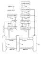
- FIG. 1is a schematic diagram of the receive buffers and their associated filters according to the prior art.
- FIG. 2is a schematic diagram of the receive buffers and their associated filters according to a first exemplary embodiment of the present invention
- FIG. 3shows details of the CAN protocol engine according to the exemplary embodiment shown in FIG. 2 ;
- FIG. 4shows a schematic diagram of the receive buffers and their associated filters according to a second exemplary embodiment of the present invention.
- FIG. 5shows details of a bit comparator unit according to FIG. 4 .
- Buffer 120designated as a message assembly buffer (MAB), functions only to monitor the CAN logic bus (not shown) for incoming messages.
- the MAB 120holds a de-stuffed bit stream from the bus line.
- the bit streamconsists of a message, i.e. a data frame, remote frame, or other frame, comprising an identifier and data field (not shown).
- the MAB 120allows receive buffers 118 and 122 parallel access to the message.
- MAB 120also allows acceptance filters 106 and 116 access to the identifier portion of the message. Parallel transfer of the bit stream message to receive buffers 118 or 122 is not allowed until acceptance masks 102 and 108 and acceptance filters 104 , 106 , 110 , 112 , 114 , and 116 apply an acceptance match test to the message.
- Programmable acceptance filter masks 102 and 108are used to select which bits of the unstuffed bit-stream message should be compared with the contents of acceptance filters 104 and 106 , and 110 , 112 , 114 , and 116 .
- the acceptance match testproceeds as follows: Filters 104 , 106 , 110 , 112 , 114 , and 116 receive the identifier field of the message and compare that field to filter values. If there is a match between the identifier field and a filter value, then the message is loaded into the matching filter's corresponding receive buffer 118 or 122 . Filters 104 and 106 are connected to buffer 118 , filters 110 , 112 , 114 , and 116 to buffer 122 .
- Buffer 118is the higher priority buffer and has message acceptance filters 104 and 106 associated with it.
- Buffer 122is the lower priority buffer and has acceptance filters 110 , 112 , 114 , and 116 associated with it. That fewer filters are associated with buffer 118 than with buffer 122 means that buffer 118 is more restrictive than buffer 122 . The more restrictive buffer 118 has, by implication, the higher criticality associated with it.
- receive buffer 118designated as the first high-priority buffer
- receive buffer 118will receive the first high-priority message.
- MAB 120finds that buffer 118 is currently occupied by a high-priority message.
- MAB 120then directs buffer 122 , designated as the second high-priority buffer, to receive the second high-priority message.
- Buffers 118 and 122are ranked, respectively, as the first high-priority buffer and the second high-priority buffer in this scenario.
- the central processing unit(CPU) (not shown) may operate on one of the receive buffers 118 and 122 , while the other is available for reception or holding a previously received message.
- the protocol in the case of the arrival of two high-priority messagesis effected by the BUKT bit in the control registers (not shown) of receive buffers 118 and 122 .
- Table Idepicts and explains the control register of receive buffer 118 , wherein R/W means Readable/Writable bit, and wherein R means Read-only bit.
- the BUKT bitimplements the priority-based protocol of the present invention.
- Table IIdepicts and explains the control register of receive buffer 122 .
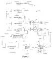
- FIG. 2shows an arrangement of buffers and associated mask and filter/comparator registers according to an exemplary embodiment of the present invention.
- FIG. 2shows only relevant elements of the arrangements. This embodiment comprises storing and comparing in a parallel way.
- Two mask registers 210 and 220are coupled with a plurality of filter registers & comparator units 230 , 240 (only two are shown in FIG. 2 ). Each mask register can be selected through respective select lines 215 and 225 .
- the units 230 , 240receive the identifier field from a message assembly register 270 .
- Each unit 230 , 240has an associated 4 bit buffer pointer 250 , 260 .
- the output of these buffer pointers 250 , 260are coupled through buffer pointer bus 255 with the input of address register 290 .
- the output of address register 290is coupled with the address input of a buffer memory 280 .
- a message assembly register 270receives a serial data stream from a CAN protocol engine 275 and assembles the identifier and additional transmitted data. Message assembly register 270 outputs the identifier in parallel to the filter register & comparator units 230 , 240 and the data in parallel to the data input of buffer memory 280 .
- the buffer memory 280can be designed as a dual port memory. One port is coupled with the message assembly register and the other port is coupled with a central processing unit (CPU) 205 of a microcontroller which includes the CAN module.
- the CPU 205is coupled with a memory 206 , for example a random access memory for storing program and data information.
- the functionality of the filters/comparators and the masksis identical to the functionality as described above.
- the plurality of filter registers & comparator units 230 . . . 240do not have a static assignment to specific buffers.
- Each filter & comparator units 230 . . . 240can be dynamically assigned to any buffer within the buffer memory 280 .
- Each filter & comparator unit 230 , 240therefore has an associated buffer pointer 250 , 260 .
- Each buffer pointer 250 , 260is programmable (connection with CPU not shown) and comprises in the shown exemplary embodiment 4 bits to address the 16 buffers within buffer memory 280 .
- Filter & comparator unit 230 , 240compare the identifier in a parallel way. Each time a filter & comparator unit, for example, filter & comparator units 230 , matches an identifier supplied from message assembly register 270 , the filter generates an acceptance signal. In addition, one of two mask registers can be selected. The mask registers 210 , 220 define which bits of the filter register will be compared.
- a filter & comparator unit 230If acceptance signal of a filter & comparator unit 230 is generated, then this signal forces the content of buffer pointer 250 onto the buffer pointer bus 255 where the address register 290 subsequently latches it. The respective data from message assembly register 270 is then stored at the respective addressed location within buffer memory 280 . Since the buffer pointer can be loaded with any value, a filter & comparator unit 230 , 240 can be programmed to point to any of up to 16 message buffers. Thus, filters can be easily switched between receive buffers. This provides a flexible use of resources. The same tasks as in the prior art can therefore be accomplished with less elements and thus less silicon real estate.
- the CPU 205is, as described above, preferably coupled with the buffer memory 280 through a second port of the buffer memory 280 .
- CAN protocol engine 275 and CPU 205can access buffers within the buffer memory 280 independently.
- FIG. 3shows the CAN protocol engine 275 in more detail.
- the protocol engine 275combines several functional blocks.
- the heart of the engine 275is the protocol finite state machine 310 (FSM).
- FSMprotocol finite state machine
- This state machinesequences through the messages on a bit by bit basis, changing states of the machine as various fields of various frame types are transmitted or received.
- the FSM 310is a sequencer controlling the sequential data stream between the RX/TX shift register 320 , 325 , the CRC Register 330 , and the receive bus line 350 and transmit bus line 360 , respectively.
- the shift registers 320 , 325can be part of the message assembly register 270 .
- Additional components 355 and 365are provided to convert the data streams and adapt to the respective timing on the bus lines 350 and 360 .
- the FSMalso controls the Error Management Logic 340 (EML) and the parallel data stream RecData between the TX/RX shift register 320 , 325 and other components of the CAN module.
- EMLError Management Logic
- RecDataRecData between the TX/RX shift register 320 , 325 and other components of the CAN module.
- the processes of reception arbitration, transmission, and error signalingare performed according to the CAN protocol.
- the FSM 310also handles any automatic transmission of messages on the bus line.
- the data interface to the protocol engine 275consists of byte wide transmit and receive data. Rather than assembling and shifting an entire frame, the frames are broken into bytes.
- a receive or transmit address from the protocol FSM 310signifies which byte of the frame is current.
- the appropriate byte from the transmit bufferis selected and presented to the engine, which then uses an 8-bit shift register to serialize the data.
- an 8-bit shift registerassembles a byte which is then loaded within the appropriate byte in the message assembly buffer 270 .
- the cyclic redundancy check register 330generates the Cyclic Redundancy Check (CRC) code to be transmitted over the data bytes and checks the CRC code of incoming messages.
- the Error Management Logic (EML) 340is responsible for the fault confinement of the CAN device. Its counters, the Receive Error Counter and the Transmit Error Counter, are incremented and decremented by commands from the Bit stream processor. According to the values of the error counters, the CAN controller is set into states error active, error passive or bus off.
- the Bit Timing Logic (BTL) within unit 355monitors the bus line input and handles the bus line related bit timing according to the CAN protocol.
- the BTLsynchronizes on a recessive to dominant bus line transition at Start of Frame and on any further recessive to dominant bus line transition, if the CAN controller itself does not transmit a dominant bit.
- the BTLalso provides programmable time segments to compensate for the propagation delay time and for phase shifts and in defining the position of the Sample Point in the bit time.
- the programming of the BTLdepends on the baud rate and on external physical delay times.
- FIG. 4shows another exemplary embodiment of the present invention comprising a serial comparison.
- FIG. 4shows only the CAN module 400 .
- a first and second mask register 415 and 420are bit-wise addressable and comprise a single output bit.
- a plurality of filter registers 0 . . . N(only two are shown) are designated by numerals 425 and 430 .
- the filter registers 425 , 430also comprise a single output bit and are bit-wise addressable.
- mask registers 415 and 420 as well as all filter registers 425 , 430are read and write-able in a parallel mode by a central processing unit (not shown in FIG. 4 ).
- a sequencer and control unit 410operates as a bit select unit and generates address signals which are fed to mask register 415 and 420 and all filter registers 425 , 430 .
- Each filter register 425 , 430comprises an associated bit comparator unit 435 , 440 .
- the bit output signal of mask register 415 and 420are fed to first and second inputs of bit comparator units 435 , 440 .
- each bit output of the filter registers 425 , 430is fed to a third input of their associated bit comparator unit 435 , 440 .
- a bit stream signal from a CAN busis provided by a CAN protocol engine 495 and fed to a fourth input of each bit comparator unit 435 , 440 .
- Filter registers 425 , 430can provided additional storage bits which are coupled with a fifth input of each associated bit comparator unit.
- the output of each bit comparator unit 435 , 440carries the acceptance signal and is coupled with a control input of an associated buffer pointer 445 , 450 .
- An OR gate 455is provided having as many inputs as the number of filter registers. Each input receives an acceptance signal from a respective bit comparator unit 435 , 440 .
- the output of each buffer pointer 445 and 450are coupled with a buffer pointer bus 462 which is connected to an address input of a multiple function address register 460 .
- the outputs of OR gate 455is coupled with a control input of multiple function register 460 .
- Multiple function register 460further comprises a mode control input 465 , a first status output 475 indicating whether a buffer memory 485 is full, a second status output 480 indicating whether a buffer memory 485 is empty, and an up/down control input for a counter function of the multiple function address register 460 .
- An address output 464 of multiple function address register 460is coupled with the address input of buffer memory 485 .
- Buffer memory 485is preferably a dual port memory whose first port is coupled with a message assembly buffer shift register 490 receiving the serial data stream from the CAN protocol engine 495 . The second port of is coupled with a central processing unit (not shown).
- This embodimentprovides additional options to write data from a serial data stream into the buffer memory 485 . Furthermore, the comparison of filter values stored in filter registers 425 , 430 and transmitted identifiers is done in a bit-wise fashion rather than in parallel. Thus, parallel comparators, which need a relatively big amount of silicon real estate, are avoided.
- a serial data stream provided by CAN protocol engine 495comprises an identifier which is fed directly to all bit comparator units 435 , 440 . Sequencer and control unit 410 address the mask registers 415 , 420 and all filter registers 425 , 430 to output a corresponding bit to the bit comparator units 435 , 440 .
- the bit comparator units 435 , 440compare all filter register bits with the respective identifier bit within a frame. The result is further processed by comparing it to the respective mask register bit. To this end, the additional storage bits of each filter register 425 , 430 can indicated which mask register should be used for this comparison. This function will be explained in more detail below.
- the final comparison resultwill be accumulated for all bits of each identifier within a frame. If a single comparison fails the acceptance signal will not be generated. If every bit comparison is positive the acceptance signal will be fed to the respective buffer pointer 445 , 450 and to a respective input of OR gate 455 .
- a central processing unitcan control the multiple function address register 460 in the following manner. Two modes can be selected through mode signal 465 . In the first mode the buffer pointer 445 , 450 work in the same way as described above in conjunction with FIG. 2 . Multiple function address register 460 latches an address which has been put on address bus 462 and addresses buffer memory 485 stores data in parallel that has been assembled by message assembly buffer shift register 490 .
- a second modecan be selected by means of control signal 465 .
- the buffer pointers 445 , 450are not needed and therefore their output signals will be neglected.
- the actual address register within multiple function address registeris set, for example, to “Fh” and the status signal 480 will signal an empty buffer. Every time a bit comparator unit 435 , 440 generates an acceptance signal this triggers an increment function of the multiple function address register 460 and its content will therefore be incremented by 1.
- the first data assembled by message assembly buffer shift register 490will be stored at memory location 0 .
- This functionprovides a so called FIFO functionality of the CAN module in which no buffer is associated with any bit comparator.
- the buffer memory 485will be sequentially written until the address reaches Fh again which indicates that the buffer is full unless the CPU has read previous entries. A full buffer memory 485 will be indicated by control signal 475 .
- control signal 470can select between a incrementing and decrementing function of the address register. Additional signals can be provided by the CPU to indicate whether a buffer value has been read for generating the proper status signals 475 , and 480 and to ensure that no value will be overwritten before it has been fetched by the CPU. Furthermore, the increment/decrement function of the address register can of course be performed before storing of the data or after storing of the data.
- FIG. 5shows a bit comparator unit 435 , 440 in more detail. The details are shown for Bit comparator unit 0 but apply for all other bit comparator units accordingly.
- the outputs of mask register 415 and 420are coupled with first and second inputs of a 4:1 multiplexer 520 . Additional input 560 and 570 can be provided at the third and fourth input of multiplexer 520 .
- Filter register 425comprises, for example, two additional outputs which are coupled with the select input of multiplexer 520 .
- the output of multiplexer 520is connected to the first input of a NOR gate 530 .
- NOR gate 530operates as a validation unit indicating whether a comparison result will be used or ignored.
- the second input of NOR gate 530is coupled with the output of an Exclusive NOR gate 510 whose first input receives the bit output signal from filter register 425 and whose second input receives the serial data stream from CAN protocol engine 495 .
- the output of NOR gate 530is coupled with the control input of a D-Flip-Flop 540 .
- the D-input of D-Flip-Flop 540receives a logical low signal.
- the acceptance signalis carried at the negating output 550 of D-Flip-Flop 540 .
- the first comparison stageis formed by Exclusive NOR gate 510 .
- the identifier bits of the serial bit streamare compared with the respective bits of filter register 425 .
- Sequencer unit 410selects the respective bits within filter register 425 .
- Filter register 425comprises additional data bits which indicate which mask register should be used. In this exemplary embodiment four different values can be selected. Either one of the mask registers 415 or 420 can be selected or a third value can be provided by another filter register, for example a filter register 15 (not shown).
- the fourth possible selection 570can be used to indicate that no mask will be used by providing a respective level, for example, a logical “1”. Thus, each filter register 425 , 430 can be assigned an individual mask function.
- the selected mask valuewill be put at the first input of NOR gate 530 . If the mask value indicates that the respective bit in filter register 425 should be used NOR gate 530 will operate as a controllable switch and feed the comparison result of Exclusive NOR gate 510 to the control input D-Flip-Flop 540 . If the result of one comparison is negative indicating no match and the respective mask bit is valid, D-Flip-Flop 540 will be cleared and no acceptance signal 550 will be generated after the last identifier bit has been compared.
- any other type of appropriate logiccan be used to implement the comparator.
- controllable switches, equivalent Boolean operators, etc.can be used.
- the validation unitcan be either put in front of the comparator or after the comparator.
- the essential function of a validation unitis to either incorporate selected bits or exclude them from comparison.
Landscapes
- Engineering & Computer Science (AREA)
- Computer Networks & Wireless Communication (AREA)
- Signal Processing (AREA)
- Information Transfer Systems (AREA)
Abstract
Description
| TABLE I | |||||||
| bit7 | bit6 | bit5 | bit4 | bit3 | bit2 | bit1 | bit0 |
| R/W | R/W | R/W | R/W | R/W | R/W | R | R/W |
- bit7: Message Ready Status
- 1=Receive Buffer contains a valid received message
- 0=Receive Buffer open to receive new message
- Bit is only set by CAN module, bit is only cleared by CPU.
- bit6-5: Receive Buffer Operating Mode
- 11=receive all messages including those with errors
- 10=receive only valid messages with extended identifiers
- 01=receive only valid messages with standard identifiers
- 00=receive all valid messages
- bit4: Message Reception Interrupt Enable
- 1=Interrupt Enabled
- 0=Interrupt Disabled
- bit3: Received Remote Transfer Request
- 1=Remote Transfer Request Received
- 0=No Remote Transfer Request Received
- bit2: (BUKT) Enable Overflow to Receive
Buffer 122- 1=Receive
Buffer 118 Overflow Will Write to Buffer122 - 0=No Overflow to Buffer122 Allowed
- 1=Receive
- bit1: Read Only Copy of bit2 (BUKT)
- bit0: Indicates which acceptance filter enabled the message reception
- 1=acceptance filter associated with
Buffer 122 - 0=acceptance filter associated with
Buffer 118
- 1=acceptance filter associated with
| TABLE II | |||||||
| bit7 | bit6 | bit5 | bit4 | bit3 | bit2 | bit1 | bit0 |
| R/W | R/W | R/W | R/W | R/W | R/W | R/W | R/W |
- bit7: Message Ready Status
- 1=Receive Buffer contains a valid received message
- 0=Receive Buffer open to receive new message
- Bit is only set by CAN module, bit is only cleared by CPU.
- bit6-5: Receive Buffer Operating Mode [these bits are optional]
- 11=receive all messages including those with errors
- 10=receive only valid messages with extended identifiers
- 01=receive only valid messages with standard identifiers
- 00=receive all valid messages
- bit4: Message Reception Interrupt Enable
- 1=Interrupt Enabled
- 0=Interrupt Disabled
- bit3: Received Remote Transfer Request
- 1=Remote Transfer Request Received
- 0=No Remote Transfer Request Received
- bit2-0: Indicates which acceptance filter enabled the message reception
- 101=
acceptance filter 116 - 100=
acceptance filter 114 - 011=
acceptance filter 112 - 010=
acceptance filter 110 - 001=acceptance filter106 [only if BUKT bit set to “1” in control register for buffer118]
- 000=acceptance filter104 [only if BUKT bit set to “1” in control register for buffer118]
- 101=
Claims (25)
Priority Applications (8)
| Application Number | Priority Date | Filing Date | Title |
|---|---|---|---|
| US09/957,061US7076517B2 (en) | 2001-09-20 | 2001-09-20 | Serial communication device with dynamic filter allocation |
| PCT/US2002/028661WO2003025740A2 (en) | 2001-09-20 | 2002-09-10 | Serial communication device with dynamic filter allocation |
| KR1020047004106AKR100660437B1 (en) | 2001-09-20 | 2002-09-10 | Serial communication device with dynamic filter assignment |
| AU2002331837AAU2002331837A1 (en) | 2001-09-20 | 2002-09-10 | Serial communication device with dynamic filter allocation |
| DE60234357TDE60234357D1 (en) | 2001-09-20 | 2002-09-10 | NUNG OF DYNAMIC FILTERS |
| AT02768828TATE448614T1 (en) | 2001-09-20 | 2002-09-10 | DEVICE FOR SERIAL COMMUNICATION SYSTEM WITH ASSIGNMENT OF DYNAMIC FILTERS |
| CN02822749ACN100586092C (en) | 2001-09-20 | 2002-09-10 | Serial communication device with dynamic filter assignment |
| EP02768828AEP1430653B1 (en) | 2001-09-20 | 2002-09-10 | Serial communication device with dynamic filter allocation |
Applications Claiming Priority (1)
| Application Number | Priority Date | Filing Date | Title |
|---|---|---|---|
| US09/957,061US7076517B2 (en) | 2001-09-20 | 2001-09-20 | Serial communication device with dynamic filter allocation |
Publications (2)
| Publication Number | Publication Date |
|---|---|
| US20030056016A1 US20030056016A1 (en) | 2003-03-20 |
| US7076517B2true US7076517B2 (en) | 2006-07-11 |
Family
ID=25499021
Family Applications (1)
| Application Number | Title | Priority Date | Filing Date |
|---|---|---|---|
| US09/957,061Expired - LifetimeUS7076517B2 (en) | 2001-09-20 | 2001-09-20 | Serial communication device with dynamic filter allocation |
Country Status (1)
| Country | Link |
|---|---|
| US (1) | US7076517B2 (en) |
Cited By (5)
| Publication number | Priority date | Publication date | Assignee | Title |
|---|---|---|---|---|
| US20060142061A1 (en)* | 2004-12-23 | 2006-06-29 | Peter Steffan | Dual module clock supply for CAN communication module |
| US7296312B2 (en)* | 2002-09-06 | 2007-11-20 | Hill-Rom Services, Inc. | Hospital bed |
| US20100017490A1 (en)* | 2001-09-20 | 2010-01-21 | Microchip Technology Incorporated | Serial Communications Device with Dynamic Allocation of Acceptance Masks Using Serial Implementation |
| US9009893B2 (en) | 1999-12-29 | 2015-04-21 | Hill-Rom Services, Inc. | Hospital bed |
| US9089459B2 (en) | 2013-11-18 | 2015-07-28 | Völker GmbH | Person support apparatus |
Families Citing this family (5)
| Publication number | Priority date | Publication date | Assignee | Title |
|---|---|---|---|---|
| JP4080980B2 (en) | 2003-09-26 | 2008-04-23 | 三菱電機株式会社 | Electronic control unit |
| EP2882144B1 (en)* | 2008-03-10 | 2017-03-01 | Robert Bosch Gmbh | Method and filter assembly for filtering incoming messages transmitted over a serial bus of a communication network in a participant of the network |
| US8650341B2 (en)* | 2009-04-23 | 2014-02-11 | Microchip Technology Incorporated | Method for CAN concatenating CAN data payloads |
| CN101908974B (en)* | 2010-07-16 | 2012-05-23 | 北京航天发射技术研究所 | Heat switching system and heat switching method of dual-redundant CAN bus |
| CN103684719B (en)* | 2013-12-10 | 2017-02-15 | 中国船舶重工集团公司第七0九研究所 | Network dual-redundancy hot swap method independent of platforms |
Citations (14)
| Publication number | Priority date | Publication date | Assignee | Title |
|---|---|---|---|---|
| US3623011A (en)* | 1969-06-25 | 1971-11-23 | Bell Telephone Labor Inc | Time-shared access to computer registers |
| US4383297A (en)* | 1979-09-29 | 1983-05-10 | Plessey Overseas Limited | Data processing system including internal register addressing arrangements |
| US5600782A (en) | 1993-08-24 | 1997-02-04 | National Semiconductor Corporation | Can interface with enhanced fault confinement |
| US5901070A (en) | 1995-06-30 | 1999-05-04 | Siemens Energy & Automation, Inc. | Voltage regulator controller having means for automatic configuration of accessory devices |
| US6122713A (en) | 1998-06-01 | 2000-09-19 | National Instruments Corporation | Dual port shared memory system including semaphores for high priority and low priority requestors |
| EP1085722A2 (en) | 1999-09-15 | 2001-03-21 | Koninklijke Philips Electronics N.V. | End-of-message handling and interrupt generation in a CAN module providing hardware assembly of multi-frame CAN messages |
| US20010042137A1 (en) | 2000-05-11 | 2001-11-15 | Nissan Motor Co., Ltd. | Communications network system using gateway |
| US20020164242A1 (en) | 2001-01-26 | 2002-11-07 | Brian Wehrung | Control system for transfer and buffering |
| US20030051061A1 (en) | 2001-09-04 | 2003-03-13 | Peter Hank | Acceptance filter |
| WO2003025740A2 (en) | 2001-09-20 | 2003-03-27 | Microchip Technology Incorported | Serial communication device with dynamic filter allocation |
| US6587968B1 (en) | 1999-07-16 | 2003-07-01 | Hewlett-Packard Company | CAN bus termination circuits and CAN bus auto-termination methods |
| US6631431B1 (en)* | 1999-09-15 | 2003-10-07 | Koninklijke Philips Electronics N.V. | Semaphore coding method to ensure data integrity in a can microcontroller and a can microcontroller that implements this method |
| US6732254B1 (en)* | 1999-09-15 | 2004-05-04 | Koninklijke Philips Electronics N.V. | Can device featuring advanced can filtering and message acceptance |
| US6912594B2 (en)* | 2001-09-20 | 2005-06-28 | Microchip Technology Incorporated | Serial communication device with multi-mode operation of message receive buffers |
Family Cites Families (1)
| Publication number | Priority date | Publication date | Assignee | Title |
|---|---|---|---|---|
| US6655860B2 (en)* | 2000-06-08 | 2003-12-02 | Fuji Photo Film Co., Ltd. | Photosensitive material processing apparatus |
- 2001
- 2001-09-20USUS09/957,061patent/US7076517B2/ennot_activeExpired - Lifetime
Patent Citations (14)
| Publication number | Priority date | Publication date | Assignee | Title |
|---|---|---|---|---|
| US3623011A (en)* | 1969-06-25 | 1971-11-23 | Bell Telephone Labor Inc | Time-shared access to computer registers |
| US4383297A (en)* | 1979-09-29 | 1983-05-10 | Plessey Overseas Limited | Data processing system including internal register addressing arrangements |
| US5600782A (en) | 1993-08-24 | 1997-02-04 | National Semiconductor Corporation | Can interface with enhanced fault confinement |
| US5901070A (en) | 1995-06-30 | 1999-05-04 | Siemens Energy & Automation, Inc. | Voltage regulator controller having means for automatic configuration of accessory devices |
| US6122713A (en) | 1998-06-01 | 2000-09-19 | National Instruments Corporation | Dual port shared memory system including semaphores for high priority and low priority requestors |
| US6587968B1 (en) | 1999-07-16 | 2003-07-01 | Hewlett-Packard Company | CAN bus termination circuits and CAN bus auto-termination methods |
| EP1085722A2 (en) | 1999-09-15 | 2001-03-21 | Koninklijke Philips Electronics N.V. | End-of-message handling and interrupt generation in a CAN module providing hardware assembly of multi-frame CAN messages |
| US6732254B1 (en)* | 1999-09-15 | 2004-05-04 | Koninklijke Philips Electronics N.V. | Can device featuring advanced can filtering and message acceptance |
| US6631431B1 (en)* | 1999-09-15 | 2003-10-07 | Koninklijke Philips Electronics N.V. | Semaphore coding method to ensure data integrity in a can microcontroller and a can microcontroller that implements this method |
| US20010042137A1 (en) | 2000-05-11 | 2001-11-15 | Nissan Motor Co., Ltd. | Communications network system using gateway |
| US20020164242A1 (en) | 2001-01-26 | 2002-11-07 | Brian Wehrung | Control system for transfer and buffering |
| US20030051061A1 (en) | 2001-09-04 | 2003-03-13 | Peter Hank | Acceptance filter |
| WO2003025740A2 (en) | 2001-09-20 | 2003-03-27 | Microchip Technology Incorported | Serial communication device with dynamic filter allocation |
| US6912594B2 (en)* | 2001-09-20 | 2005-06-28 | Microchip Technology Incorporated | Serial communication device with multi-mode operation of message receive buffers |
Non-Patent Citations (3)
| Title |
|---|
| International Search Report PCT/US02/28661, 8 pages. |
| National Semiconductor Corp: "8-bit CMOS ROM based Microcontroller with 2k Memory, Comparators, and CAN Interface", URL:http://www.national.com/ds/CO/COP884B, 57 pages. |
| National Semiconductor Corp: "Replacing Dedicated Protocol Controllers with Code Efficient and Configurable Microcontrollers-Low Speed CAN Network Applications", URL:http://www.national.com/an/AN/AN-1048.pdf, 8 pages. |
Cited By (9)
| Publication number | Priority date | Publication date | Assignee | Title |
|---|---|---|---|---|
| US9009893B2 (en) | 1999-12-29 | 2015-04-21 | Hill-Rom Services, Inc. | Hospital bed |
| US10251797B2 (en) | 1999-12-29 | 2019-04-09 | Hill-Rom Services, Inc. | Hospital bed |
| US20100017490A1 (en)* | 2001-09-20 | 2010-01-21 | Microchip Technology Incorporated | Serial Communications Device with Dynamic Allocation of Acceptance Masks Using Serial Implementation |
| US7979594B2 (en)* | 2001-09-20 | 2011-07-12 | Microchip Technology Incorporated | Serial communications device with dynamic allocation of acceptance masks using serial implementation |
| US7296312B2 (en)* | 2002-09-06 | 2007-11-20 | Hill-Rom Services, Inc. | Hospital bed |
| US7703158B2 (en) | 2002-09-06 | 2010-04-27 | Hill-Rom Services, Inc. | Patient support apparatus having a diagnostic system |
| US20060142061A1 (en)* | 2004-12-23 | 2006-06-29 | Peter Steffan | Dual module clock supply for CAN communication module |
| US7512827B2 (en)* | 2004-12-23 | 2009-03-31 | Texas Instruments Incorporated | Dual module clock supply for CAN communication module |
| US9089459B2 (en) | 2013-11-18 | 2015-07-28 | Völker GmbH | Person support apparatus |
Also Published As
| Publication number | Publication date |
|---|---|
| US20030056016A1 (en) | 2003-03-20 |
Similar Documents
| Publication | Publication Date | Title |
|---|---|---|
| US8650356B2 (en) | Microcontroller with CAN module | |
| US7979594B2 (en) | Serial communications device with dynamic allocation of acceptance masks using serial implementation | |
| US8650341B2 (en) | Method for CAN concatenating CAN data payloads | |
| US5590122A (en) | Method and apparatus for reordering frames | |
| US5619497A (en) | Method and apparatus for reordering frames | |
| US5604867A (en) | System for transmitting data between bus and network having device comprising first counter for providing transmitting rate and second counter for limiting frames exceeding rate | |
| US6944739B2 (en) | Register bank | |
| US5812792A (en) | Use of video DRAM for memory storage in a local area network port of a switching hub | |
| US6912594B2 (en) | Serial communication device with multi-mode operation of message receive buffers | |
| EP2038744B1 (en) | Method and system of grouping interrupts from a time-dependent data storage means | |
| EP1430653B1 (en) | Serial communication device with dynamic filter allocation | |
| US5557266A (en) | System for cascading data switches in a communication node | |
| KR19980703473A (en) | Window comparator | |
| US7076517B2 (en) | Serial communication device with dynamic filter allocation | |
| KR20010043460A (en) | Digital communications processor | |
| US20090327545A1 (en) | Method for transmitting a datum from a time-dependent data storage means | |
| US6912566B1 (en) | Memory device and method for operating the memory device | |
| US7747904B1 (en) | Error management system and method for a packet switch | |
| US11487682B1 (en) | Priority queue sorting system and method with deterministic and bounded latency | |
| US6741602B1 (en) | Work queue alias system and method allowing fabric management packets on all ports of a cluster adapter |
Legal Events
| Date | Code | Title | Description |
|---|---|---|---|
| AS | Assignment | Owner name:MICROCHIP TECHNOLOGY INCORPORATED, ARIZONA Free format text:ASSIGNMENT OF ASSIGNORS INTEREST;ASSIGNOR:BARTLING, JAMES;REEL/FRAME:012202/0260 Effective date:20010802 | |
| STCF | Information on status: patent grant | Free format text:PATENTED CASE | |
| FPAY | Fee payment | Year of fee payment:4 | |
| FPAY | Fee payment | Year of fee payment:8 | |
| AS | Assignment | Owner name:JPMORGAN CHASE BANK, N.A., AS ADMINISTRATIVE AGENT, ILLINOIS Free format text:SECURITY INTEREST;ASSIGNOR:MICROCHIP TECHNOLOGY INCORPORATED;REEL/FRAME:041675/0617 Effective date:20170208 Owner name:JPMORGAN CHASE BANK, N.A., AS ADMINISTRATIVE AGENT Free format text:SECURITY INTEREST;ASSIGNOR:MICROCHIP TECHNOLOGY INCORPORATED;REEL/FRAME:041675/0617 Effective date:20170208 | |
| MAFP | Maintenance fee payment | Free format text:PAYMENT OF MAINTENANCE FEE, 12TH YEAR, LARGE ENTITY (ORIGINAL EVENT CODE: M1553) Year of fee payment:12 | |
| AS | Assignment | Owner name:JPMORGAN CHASE BANK, N.A., AS ADMINISTRATIVE AGENT, ILLINOIS Free format text:SECURITY INTEREST;ASSIGNORS:MICROCHIP TECHNOLOGY INCORPORATED;SILICON STORAGE TECHNOLOGY, INC.;ATMEL CORPORATION;AND OTHERS;REEL/FRAME:046426/0001 Effective date:20180529 Owner name:JPMORGAN CHASE BANK, N.A., AS ADMINISTRATIVE AGENT Free format text:SECURITY INTEREST;ASSIGNORS:MICROCHIP TECHNOLOGY INCORPORATED;SILICON STORAGE TECHNOLOGY, INC.;ATMEL CORPORATION;AND OTHERS;REEL/FRAME:046426/0001 Effective date:20180529 | |
| AS | Assignment | Owner name:WELLS FARGO BANK, NATIONAL ASSOCIATION, AS NOTES COLLATERAL AGENT, CALIFORNIA Free format text:SECURITY INTEREST;ASSIGNORS:MICROCHIP TECHNOLOGY INCORPORATED;SILICON STORAGE TECHNOLOGY, INC.;ATMEL CORPORATION;AND OTHERS;REEL/FRAME:047103/0206 Effective date:20180914 Owner name:WELLS FARGO BANK, NATIONAL ASSOCIATION, AS NOTES C Free format text:SECURITY INTEREST;ASSIGNORS:MICROCHIP TECHNOLOGY INCORPORATED;SILICON STORAGE TECHNOLOGY, INC.;ATMEL CORPORATION;AND OTHERS;REEL/FRAME:047103/0206 Effective date:20180914 | |
| AS | Assignment | Owner name:JPMORGAN CHASE BANK, N.A., AS ADMINISTRATIVE AGENT, DELAWARE Free format text:SECURITY INTEREST;ASSIGNORS:MICROCHIP TECHNOLOGY INC.;SILICON STORAGE TECHNOLOGY, INC.;ATMEL CORPORATION;AND OTHERS;REEL/FRAME:053311/0305 Effective date:20200327 | |
| AS | Assignment | Owner name:MICROSEMI STORAGE SOLUTIONS, INC., ARIZONA Free format text:RELEASE BY SECURED PARTY;ASSIGNOR:JPMORGAN CHASE BANK, N.A, AS ADMINISTRATIVE AGENT;REEL/FRAME:053466/0011 Effective date:20200529 Owner name:ATMEL CORPORATION, ARIZONA Free format text:RELEASE BY SECURED PARTY;ASSIGNOR:JPMORGAN CHASE BANK, N.A, AS ADMINISTRATIVE AGENT;REEL/FRAME:053466/0011 Effective date:20200529 Owner name:SILICON STORAGE TECHNOLOGY, INC., ARIZONA Free format text:RELEASE BY SECURED PARTY;ASSIGNOR:JPMORGAN CHASE BANK, N.A, AS ADMINISTRATIVE AGENT;REEL/FRAME:053466/0011 Effective date:20200529 Owner name:MICROSEMI CORPORATION, CALIFORNIA Free format text:RELEASE BY SECURED PARTY;ASSIGNOR:JPMORGAN CHASE BANK, N.A, AS ADMINISTRATIVE AGENT;REEL/FRAME:053466/0011 Effective date:20200529 Owner name:MICROCHIP TECHNOLOGY INC., ARIZONA Free format text:RELEASE BY SECURED PARTY;ASSIGNOR:JPMORGAN CHASE BANK, N.A, AS ADMINISTRATIVE AGENT;REEL/FRAME:053466/0011 Effective date:20200529 | |
| AS | Assignment | Owner name:WELLS FARGO BANK, NATIONAL ASSOCIATION, MINNESOTA Free format text:SECURITY INTEREST;ASSIGNORS:MICROCHIP TECHNOLOGY INC.;SILICON STORAGE TECHNOLOGY, INC.;ATMEL CORPORATION;AND OTHERS;REEL/FRAME:053468/0705 Effective date:20200529 | |
| AS | Assignment | Owner name:WELLS FARGO BANK, NATIONAL ASSOCIATION, AS COLLATERAL AGENT, MINNESOTA Free format text:SECURITY INTEREST;ASSIGNORS:MICROCHIP TECHNOLOGY INCORPORATED;SILICON STORAGE TECHNOLOGY, INC.;ATMEL CORPORATION;AND OTHERS;REEL/FRAME:055671/0612 Effective date:20201217 | |
| AS | Assignment | Owner name:WELLS FARGO BANK, NATIONAL ASSOCIATION, AS NOTES COLLATERAL AGENT, MINNESOTA Free format text:SECURITY INTEREST;ASSIGNORS:MICROCHIP TECHNOLOGY INCORPORATED;SILICON STORAGE TECHNOLOGY, INC.;ATMEL CORPORATION;AND OTHERS;REEL/FRAME:057935/0474 Effective date:20210528 | |
| AS | Assignment | Owner name:MICROSEMI STORAGE SOLUTIONS, INC., ARIZONA Free format text:RELEASE BY SECURED PARTY;ASSIGNOR:JPMORGAN CHASE BANK, N.A., AS ADMINISTRATIVE AGENT;REEL/FRAME:059333/0222 Effective date:20220218 Owner name:MICROSEMI CORPORATION, ARIZONA Free format text:RELEASE BY SECURED PARTY;ASSIGNOR:JPMORGAN CHASE BANK, N.A., AS ADMINISTRATIVE AGENT;REEL/FRAME:059333/0222 Effective date:20220218 Owner name:ATMEL CORPORATION, ARIZONA Free format text:RELEASE BY SECURED PARTY;ASSIGNOR:JPMORGAN CHASE BANK, N.A., AS ADMINISTRATIVE AGENT;REEL/FRAME:059333/0222 Effective date:20220218 Owner name:SILICON STORAGE TECHNOLOGY, INC., ARIZONA Free format text:RELEASE BY SECURED PARTY;ASSIGNOR:JPMORGAN CHASE BANK, N.A., AS ADMINISTRATIVE AGENT;REEL/FRAME:059333/0222 Effective date:20220218 Owner name:MICROCHIP TECHNOLOGY INCORPORATED, ARIZONA Free format text:RELEASE BY SECURED PARTY;ASSIGNOR:JPMORGAN CHASE BANK, N.A., AS ADMINISTRATIVE AGENT;REEL/FRAME:059333/0222 Effective date:20220218 | |
| AS | Assignment | Owner name:MICROCHIP TECHNOLOGY INCORPORATED, ARIZONA Free format text:RELEASE BY SECURED PARTY;ASSIGNOR:JPMORGAN CHASE BANK, N.A., AS ADMINISTRATIVE AGENT;REEL/FRAME:059666/0545 Effective date:20220218 | |
| AS | Assignment | Owner name:MICROSEMI STORAGE SOLUTIONS, INC., ARIZONA Free format text:RELEASE BY SECURED PARTY;ASSIGNOR:WELLS FARGO BANK, NATIONAL ASSOCIATION, AS NOTES COLLATERAL AGENT;REEL/FRAME:059358/0001 Effective date:20220228 Owner name:MICROSEMI CORPORATION, ARIZONA Free format text:RELEASE BY SECURED PARTY;ASSIGNOR:WELLS FARGO BANK, NATIONAL ASSOCIATION, AS NOTES COLLATERAL AGENT;REEL/FRAME:059358/0001 Effective date:20220228 Owner name:ATMEL CORPORATION, ARIZONA Free format text:RELEASE BY SECURED PARTY;ASSIGNOR:WELLS FARGO BANK, NATIONAL ASSOCIATION, AS NOTES COLLATERAL AGENT;REEL/FRAME:059358/0001 Effective date:20220228 Owner name:SILICON STORAGE TECHNOLOGY, INC., ARIZONA Free format text:RELEASE BY SECURED PARTY;ASSIGNOR:WELLS FARGO BANK, NATIONAL ASSOCIATION, AS NOTES COLLATERAL AGENT;REEL/FRAME:059358/0001 Effective date:20220228 Owner name:MICROCHIP TECHNOLOGY INCORPORATED, ARIZONA Free format text:RELEASE BY SECURED PARTY;ASSIGNOR:WELLS FARGO BANK, NATIONAL ASSOCIATION, AS NOTES COLLATERAL AGENT;REEL/FRAME:059358/0001 Effective date:20220228 | |
| AS | Assignment | Owner name:MICROSEMI STORAGE SOLUTIONS, INC., ARIZONA Free format text:RELEASE BY SECURED PARTY;ASSIGNOR:WELLS FARGO BANK, NATIONAL ASSOCIATION, AS NOTES COLLATERAL AGENT;REEL/FRAME:059863/0400 Effective date:20220228 Owner name:MICROSEMI CORPORATION, ARIZONA Free format text:RELEASE BY SECURED PARTY;ASSIGNOR:WELLS FARGO BANK, NATIONAL ASSOCIATION, AS NOTES COLLATERAL AGENT;REEL/FRAME:059863/0400 Effective date:20220228 Owner name:ATMEL CORPORATION, ARIZONA Free format text:RELEASE BY SECURED PARTY;ASSIGNOR:WELLS FARGO BANK, NATIONAL ASSOCIATION, AS NOTES COLLATERAL AGENT;REEL/FRAME:059863/0400 Effective date:20220228 Owner name:SILICON STORAGE TECHNOLOGY, INC., ARIZONA Free format text:RELEASE BY SECURED PARTY;ASSIGNOR:WELLS FARGO BANK, NATIONAL ASSOCIATION, AS NOTES COLLATERAL AGENT;REEL/FRAME:059863/0400 Effective date:20220228 Owner name:MICROCHIP TECHNOLOGY INCORPORATED, ARIZONA Free format text:RELEASE BY SECURED PARTY;ASSIGNOR:WELLS FARGO BANK, NATIONAL ASSOCIATION, AS NOTES COLLATERAL AGENT;REEL/FRAME:059863/0400 Effective date:20220228 | |
| AS | Assignment | Owner name:MICROSEMI STORAGE SOLUTIONS, INC., ARIZONA Free format text:RELEASE BY SECURED PARTY;ASSIGNOR:WELLS FARGO BANK, NATIONAL ASSOCIATION, AS NOTES COLLATERAL AGENT;REEL/FRAME:059363/0001 Effective date:20220228 Owner name:MICROSEMI CORPORATION, ARIZONA Free format text:RELEASE BY SECURED PARTY;ASSIGNOR:WELLS FARGO BANK, NATIONAL ASSOCIATION, AS NOTES COLLATERAL AGENT;REEL/FRAME:059363/0001 Effective date:20220228 Owner name:ATMEL CORPORATION, ARIZONA Free format text:RELEASE BY SECURED PARTY;ASSIGNOR:WELLS FARGO BANK, NATIONAL ASSOCIATION, AS NOTES COLLATERAL AGENT;REEL/FRAME:059363/0001 Effective date:20220228 Owner name:SILICON STORAGE TECHNOLOGY, INC., ARIZONA Free format text:RELEASE BY SECURED PARTY;ASSIGNOR:WELLS FARGO BANK, NATIONAL ASSOCIATION, AS NOTES COLLATERAL AGENT;REEL/FRAME:059363/0001 Effective date:20220228 Owner name:MICROCHIP TECHNOLOGY INCORPORATED, ARIZONA Free format text:RELEASE BY SECURED PARTY;ASSIGNOR:WELLS FARGO BANK, NATIONAL ASSOCIATION, AS NOTES COLLATERAL AGENT;REEL/FRAME:059363/0001 Effective date:20220228 | |
| AS | Assignment | Owner name:MICROSEMI STORAGE SOLUTIONS, INC., ARIZONA Free format text:RELEASE BY SECURED PARTY;ASSIGNOR:WELLS FARGO BANK, NATIONAL ASSOCIATION, AS NOTES COLLATERAL AGENT;REEL/FRAME:060894/0437 Effective date:20220228 Owner name:MICROSEMI CORPORATION, ARIZONA Free format text:RELEASE BY SECURED PARTY;ASSIGNOR:WELLS FARGO BANK, NATIONAL ASSOCIATION, AS NOTES COLLATERAL AGENT;REEL/FRAME:060894/0437 Effective date:20220228 Owner name:ATMEL CORPORATION, ARIZONA Free format text:RELEASE BY SECURED PARTY;ASSIGNOR:WELLS FARGO BANK, NATIONAL ASSOCIATION, AS NOTES COLLATERAL AGENT;REEL/FRAME:060894/0437 Effective date:20220228 Owner name:SILICON STORAGE TECHNOLOGY, INC., ARIZONA Free format text:RELEASE BY SECURED PARTY;ASSIGNOR:WELLS FARGO BANK, NATIONAL ASSOCIATION, AS NOTES COLLATERAL AGENT;REEL/FRAME:060894/0437 Effective date:20220228 Owner name:MICROCHIP TECHNOLOGY INCORPORATED, ARIZONA Free format text:RELEASE BY SECURED PARTY;ASSIGNOR:WELLS FARGO BANK, NATIONAL ASSOCIATION, AS NOTES COLLATERAL AGENT;REEL/FRAME:060894/0437 Effective date:20220228 |