US7075967B2 - Wireless communication system using block filtering and fast equalization-demodulation and method of operation - Google Patents
Wireless communication system using block filtering and fast equalization-demodulation and method of operationDownload PDFInfo
- Publication number
- US7075967B2 US7075967B2US09/838,810US83881001DUS7075967B2US 7075967 B2US7075967 B2US 7075967B2US 83881001 DUS83881001 DUS 83881001DUS 7075967 B2US7075967 B2US 7075967B2
- Authority
- US
- United States
- Prior art keywords
- signal
- sequence
- symbols
- set forth
- frequency domain
- Prior art date
- Legal status (The legal status is an assumption and is not a legal conclusion. Google has not performed a legal analysis and makes no representation as to the accuracy of the status listed.)
- Expired - Lifetime, expires
Links
Images


Classifications
- H—ELECTRICITY
- H04—ELECTRIC COMMUNICATION TECHNIQUE
- H04W—WIRELESS COMMUNICATION NETWORKS
- H04W16/00—Network planning, e.g. coverage or traffic planning tools; Network deployment, e.g. resource partitioning or cells structures
- H04W16/24—Cell structures
- H04W16/28—Cell structures using beam steering
- H—ELECTRICITY
- H01—ELECTRIC ELEMENTS
- H01Q—ANTENNAS, i.e. RADIO AERIALS
- H01Q1/00—Details of, or arrangements associated with, antennas
- H01Q1/12—Supports; Mounting means
- H01Q1/22—Supports; Mounting means by structural association with other equipment or articles
- H01Q1/24—Supports; Mounting means by structural association with other equipment or articles with receiving set
- H01Q1/241—Supports; Mounting means by structural association with other equipment or articles with receiving set used in mobile communications, e.g. GSM
- H01Q1/246—Supports; Mounting means by structural association with other equipment or articles with receiving set used in mobile communications, e.g. GSM specially adapted for base stations
- H—ELECTRICITY
- H04—ELECTRIC COMMUNICATION TECHNIQUE
- H04B—TRANSMISSION
- H04B7/00—Radio transmission systems, i.e. using radiation field
- H04B7/02—Diversity systems; Multi-antenna system, i.e. transmission or reception using multiple antennas
- H04B7/022—Site diversity; Macro-diversity
- H—ELECTRICITY
- H04—ELECTRIC COMMUNICATION TECHNIQUE
- H04L—TRANSMISSION OF DIGITAL INFORMATION, e.g. TELEGRAPHIC COMMUNICATION
- H04L12/00—Data switching networks
- H04L12/02—Details
- H04L12/10—Current supply arrangements
- H—ELECTRICITY
- H04—ELECTRIC COMMUNICATION TECHNIQUE
- H04L—TRANSMISSION OF DIGITAL INFORMATION, e.g. TELEGRAPHIC COMMUNICATION
- H04L27/00—Modulated-carrier systems
- H04L27/26—Systems using multi-frequency codes
- H04L27/2601—Multicarrier modulation systems
- H04L27/2647—Arrangements specific to the receiver only
- H—ELECTRICITY
- H04—ELECTRIC COMMUNICATION TECHNIQUE
- H04M—TELEPHONIC COMMUNICATION
- H04M3/00—Automatic or semi-automatic exchanges
- H04M3/42—Systems providing special services or facilities to subscribers
- H—ELECTRICITY
- H04—ELECTRIC COMMUNICATION TECHNIQUE
- H04W—WIRELESS COMMUNICATION NETWORKS
- H04W24/00—Supervisory, monitoring or testing arrangements
- H04W24/04—Arrangements for maintaining operational condition
- H—ELECTRICITY
- H04—ELECTRIC COMMUNICATION TECHNIQUE
- H04L—TRANSMISSION OF DIGITAL INFORMATION, e.g. TELEGRAPHIC COMMUNICATION
- H04L1/00—Arrangements for detecting or preventing errors in the information received
- H04L1/004—Arrangements for detecting or preventing errors in the information received by using forward error control
- H—ELECTRICITY
- H04—ELECTRIC COMMUNICATION TECHNIQUE
- H04M—TELEPHONIC COMMUNICATION
- H04M2207/00—Type of exchange or network, i.e. telephonic medium, in which the telephonic communication takes place
- H04M2207/20—Type of exchange or network, i.e. telephonic medium, in which the telephonic communication takes place hybrid systems
- H04M2207/206—Type of exchange or network, i.e. telephonic medium, in which the telephonic communication takes place hybrid systems composed of PSTN and wireless network
- H—ELECTRICITY
- H04—ELECTRIC COMMUNICATION TECHNIQUE
- H04M—TELEPHONIC COMMUNICATION
- H04M2242/00—Special services or facilities
- H04M2242/04—Special services or facilities for emergency applications
- H—ELECTRICITY
- H04—ELECTRIC COMMUNICATION TECHNIQUE
- H04M—TELEPHONIC COMMUNICATION
- H04M2242/00—Special services or facilities
- H04M2242/06—Lines and connections with preferential service
- H—ELECTRICITY
- H04—ELECTRIC COMMUNICATION TECHNIQUE
- H04W—WIRELESS COMMUNICATION NETWORKS
- H04W4/00—Services specially adapted for wireless communication networks; Facilities therefor
- H04W4/90—Services for handling of emergency or hazardous situations, e.g. earthquake and tsunami warning systems [ETWS]
- H—ELECTRICITY
- H04—ELECTRIC COMMUNICATION TECHNIQUE
- H04W—WIRELESS COMMUNICATION NETWORKS
- H04W76/00—Connection management
- H04W76/50—Connection management for emergency connections
- H—ELECTRICITY
- H04—ELECTRIC COMMUNICATION TECHNIQUE
- H04W—WIRELESS COMMUNICATION NETWORKS
- H04W84/00—Network topologies
- H04W84/02—Hierarchically pre-organised networks, e.g. paging networks, cellular networks, WLAN [Wireless Local Area Network] or WLL [Wireless Local Loop]
- H04W84/10—Small scale networks; Flat hierarchical networks
- H04W84/14—WLL [Wireless Local Loop]; RLL [Radio Local Loop]
- H—ELECTRICITY
- H04—ELECTRIC COMMUNICATION TECHNIQUE
- H04W—WIRELESS COMMUNICATION NETWORKS
- H04W88/00—Devices specially adapted for wireless communication networks, e.g. terminals, base stations or access point devices
- H04W88/08—Access point devices
Definitions
- the present inventionis directed, in general, to communication network access systems and, more specifically, to a base station receiver in a fixed wireless access system.
- Telecommunications access systemsprovide voice, data, and multimedia transport and control between the central office (CO) of the telecommunications service provider and the subscriber (customer) premises.
- COcentral office
- a subscriberPrior to the mid-1970s, a subscriber was connected by phone lines (e.g., voice frequency (VF) pairs) directly to Class 5 switching equipment located in the central office of the telephone company.
- VFvoice frequency
- DLCdigital loop carrier
- the DLC equipmentprovided an analog phone interface, voice CODEC functions, digital data multiplexing, a transmission interface, and control and alarm functions remotely from the central office to cabinets located within business and residential locations for approximately 100 to 2000 phone line interfaces.
- This distributed access architecturegreatly reduced line lengths to the subscriber and resulted in significant savings in both wire installation and maintenance. The reduced line lengths also improved communication performance on the line provided to the subscriber.
- ISDNIntegrated Services Digital Network
- the subscriber interfaceis based on 64 kbps digitization of the VF pair for digital multiplexing into high speed digital transmission streams (e.g., T 1 /T 3 lines in North America, E 1 /E 3 lines in Europe).
- ISDNwas a logical extension of the digital network that had evolved throughout the 1980s.
- the rollout of ISDN in Europewas highly successful. However, the rollout in the United States was not successful, due in part to artificially high tariff costs which greatly inhibited the acceptance of ISDN.
- DSLdigital subscriber line
- cable modemshave been developed and deployed.
- the DLC architecturewas extended to provide remote distributed deployment at the neighborhood cabinet level using DSL access multiplexer (DSLAM) equipment.
- DSL access multiplexerDSL access multiplexer
- the increased data rates provided to the subscriberresulted in the upgrading of DLC/DSLAM transmission interfaces from T 1 /E 3 interfaces (1.5/2.0 Mbps) to high-speed DS 3 and OC 3 interfaces.
- the entire telecommunications network backbonehas undergone and is undergoing continuous upgrading to wideband optical transmission and switching equipment.
- wireless access systemshave been developed and deployed to provide broadband access to both commercial and residential subscriber premises.
- Fixed wireless broadband systemsuse a group of transceiver base stations to cover a region in the same manner as the base stations of a cellular phone system.
- the base stations of a fixed wireless broadband systemtransmit forward channel (i.e., downstream) signals in directed beams to fixed location antennas attached to the residences or offices of subscribers.
- the base stationsalso receive reverse channel (i.e., upstream) signals transmitted by broadband access equipment at the subscriber premises.
- Wireless access systemsmust address a number of unique operational and technical issues including:
- wireless access systemsUnlike wireline systems (including optical) that operate at bit error rates (BER) of 10 ⁇ 11 , wireless access systems have time varying channels that typically provide bit error rates of 10 ⁇ 3 to 10 ⁇ 6 .
- the wireless physical (PHY) layer interface and the media access control (MAC) layer interfacemust provide modulation, error correction and ARQ protocol that can detect and, where required, correct or retransmit corrupted data so that the interfaces at the network and at the subscriber site operate at approximately wire line bit error rates.
- RF propagation channelsi.e., links
- RF propagation channelsmay vary due to a number of link factors. The two most important factors are propagation loss and channel distortion. Depending of the type of channel, the propagation loss between a transmitter and a receiver increases beyond the best case line-of-sight (LOS) R 2 propagation losses to include distortion caused by multipath, shadowing, and diffraction.
- LOSline-of-sight
- Propagation pathsmay be characterized as line of sight (LOS), non-line of sight (non-LOS) with knife-edge diffraction (non-shadowed), and non-LOS with shadowing or obstruction.
- LOSline of sight
- non-LOSnon-line of sight
- non-shadowedknife-edge diffraction
- shadowing or obstructionthere is no obstruction within the Fresnel zone.
- the Fresnel zoneis the area around the line of sight that radio waves spread into after the radio waves leave the antenna. As a rule of thumb, if at least 55% of the first Fresnel zone is clear, then there is no significant distortion.
- multipathmay still be present.
- the path loss of a LOS propagation pathis approximately R 2 , where R is the path length.
- a structure or terraine.g., hill
- blocks the direct line of sightbut only partially blocks (i.e., non-shadowed) the Fresnel zone of the direct path.
- RF waves diffracted around the obstructioni.e., knife-edge diffraction
- the length of the propagation pathis increased (excess path length), which increases the path loss beyond R 2 , thereby including an additional diffraction loss component.
- the primary source of channel distortionis multipath reflection caused by reflection of the transmitted signal off objects (e.g., buildings, terrain) in the area.
- Multipath reflectioncauses the primary (direct path) signal and a number of delayed path signals to arrive at the receiver at different times.
- One way of describing the extent of multipathis to define the delay spread of the channel auto-correlation delay profile.
- the delay spreadis defined as the difference in time between the arrival of the first signal (H 1 direct path) and the arrival of the last detectable signal (H 3 longest multipath) that is X dB below the power of the first signal.
- Multipath correction techniquesincluding 1) signal processing to perform channel equalization (inverse filtering), 2) directional antennas (limit sources of multipath), and 3) spatial diversity receivers (demodulation and coherent combination of one or more antenna-receiver sources).
- modulation and associated signal processingimpacts the complexity of both the digital baseband modem and the linearity of the RF transceiver.
- Common modulation schemeshave been summarized by Falconer and Ariyavistakul in a submission to the IEEE 802.16.3 working group (D. Falconer and S. Ariyavistakuo, “Modulation and Equalization Criteria for 2 to 11 GHZ Fixed Broadband Wireless Systems,” IEEE 802.16c-00/Sep. 13, 2000).
- modulation schemesinclude: 1) orthogonal frequency division multiplexing (OFDM) based on a Fast Fourier Transform-Inverse Fast Fourier Transform (FFT/IFFT) implementation; 2) single carrier (SC) modulation with time domain adaptive equalization; and 3) single carrier modulation with frequency domain adaptive equalization.
- OFDMorthogonal frequency division multiplexing
- FFT/IFFTFast Fourier Transform-Inverse Fast Fourier Transform
- SCsingle carrier
- OFDM modulation formatsAs opposed to single carrier modems that implement equalization.
- the support for OFDM modulationis based on the computational complexity of the equalizer being a linear function of delay spread in single carrier modems, while the computational complexity of the equalizer in an OFDM system is a log function of the delay spread using efficient FFT implementations.
- this benefit in computational complexityis gained at the cost of increased RF linearity, increased frequency sensitivity, and granularity problems in the OFDM systems.
- This present inventionaddresses the design of an equalizer-demodulator for burst digital communication signals received in multipath-impaired radio channels of a wireless communications system.
- the equalizer-demodulator in the inventionemploys fast equalization techniques with reduced computational load. These techniques include computationally efficient channel estimation and equalizer filter coefficient computation algorithms.
- the channel equalizationuses 2/T fractionally spaced feedforward filters and sparse post-decision feedback filters.
- the odd and even feedforward filtersare implemented as a single block frequency domain filter using an efficient Fast Fourier transform (FFT).
- FFTFast Fourier transform
- the post-decision feedback filter of the present inventionoperates in the time domain using a sparsely populated coefficient vector to minimize computation without sacrificing the ability to compensate large multipath delays.
- the equalizer/demodulatoris coupled with a Time Division Duplex (TDD) air interface of the wireless communications system.
- TDDTime Division Duplex
- the air interfacespecifies that all subscriber transmission bursts have durations (i.e., number of symbols) equal to an integer number of FFT blocks.
- the advantageous embodiment of the present inventionis also coupled with the air interface such that the TDD burst supports FFT block size preambles. These preambles consist of Constant Amplitude Zero Auto-Correlation (CAZAC) phase shift keying (PSK) training sequences.
- CAZACConstant Amplitude Zero Auto-Correlation
- PSKphase shift keying
- the inclusion of the preamble in the subscriber uplinkis optional and under the command of the base station. This allows the base station equalizer-demodulator to track the multipath channels of individual subscribers while minimizing the preamble overhead.
- the BS transceivercomprises: 1) a receiver front-end capable of receiving data burst transmissions from the plurality of subscriber transceivers in an uplink portion of a TDD channel, wherein the receiver front-end demodulates the received data burst transmissions into a digital baseband signal in-phase (I) signal and a digital baseband quadrature (Q) signal; 2) a first frequency domain feedforward equalization filter capable of receiving the I signal and performing a Fast Fourier Transform on a block of N symbols in the I signal to produce a first symbol estimate sequence; 3) a second frequency domain feedforward equalization filter capable of receiving the Q signal and performing a Fast Fourier Transform on a block of N symbols in the Q signal to produce a second symbol
- the first frequency domain feedforward equalization filteris 2/T fractionally spaced, where T is a period of the block of the N symbols.
- the second frequency domain feedforward equalization filteris 2/T fractionally spaced, where T is a period of the block of the N symbols.
- the time domain feedback filtercomprises a delay line comprising D delay taps.
- the time domain feedback filteruses C feedback coefficients to generate the symbol correction sequence, where C is less than D.
- the feedback filteris a RAKE filter.
- the BS transceiverfurther comprises a channel estimation circuit capable of detecting a preamble sequence of symbols in at least one of the I and Q signals and producing therefrom a first plurality of feedforward coefficients usable by the first frequency domain feedforward equalization filter.
- the channel estimation circuitproduces a second plurality of feedforward coefficients usable by the first frequency domain feedforward equalization filter.
- N16.
- FIG. 1illustrates exemplary fixed wireless access network according to one embodiment of the present invention
- FIGS. 2A and 2Billustrate a conventional transmitter and a conventional receiver for use in a prior art wireless access network that implements single carrier frequency domain equalization (SC-DFE);
- SC-DFEsingle carrier frequency domain equalization
- FIGS. 3A and 3Billustrate a conventional transmitter and a conventional receiver for use in a prior art wireless access network that implements orthogonal frequency domain multiplexing (OFDM) modulation;
- OFDMorthogonal frequency domain multiplexing
- FIG. 4illustrates a burst mode processing equalizer-demodulator for use in the RF modem of the exemplary transceiver base station according to one embodiment of the present invention
- FIG. 5Aillustrates an exemplary time division duplex (TDD) frame according to one embodiment of the present invention
- FIG. 5Billustrates an exemplary transmission burst containing a frame with a single forward error correction (FEC) block according to one embodiment of the present invention
- FIG. 5Cillustrates an exemplary transmission burst containing a frame having multiple FEC blocks according to another embodiment of the present invention.
- FIGS. 1 through 5discussed below, and the various embodiments used to describe the principles of the present invention in this patent document are by way of illustration only and should not be construed in any way to limit the scope of the invention. Those skilled in the art will understand that the principles of the present invention may be implemented in any suitably arranged wireless access network.
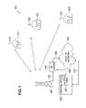
- FIG. 1illustrates exemplary fixed wireless access network 100 according to one embodiment of the present invention.
- Fixed wireless network 100comprises a plurality of transceiver base stations, including exemplary transceiver base station 110 , that transmit forward channel (i.e., downlink or downstream) broadband signals to a plurality of subscriber premises, including exemplary subscriber premises 121 , 122 and 123 , and receive reverse channel (i.e., uplink or upstream) broadband signals from the plurality of subscriber premises.
- Subscriber premises 121 – 123transmit and receive via fixed, externally-mounted antennas 131 – 133 , respectively.
- Subscriber premises 121 – 123may comprise many different types of residential and commercial buildings, including single family homes, multi-tenant offices, small business enterprises (SBE), medium business enterprises (MBE), and so-called “SOHO” (small office/home office) premises.
- SBEsmall business enterprises
- MBEmedium business enterprises
- SOHOsmall office/home office
- the transceiver base stationsreceive the forward channel (i.e., downlink) signals from external network 150 and transmit the reverse channel (i.e., uplink) signals to external network 150 .
- External network 150may be, for example, the public switched telephone network (PSTN) or one or more data networks, including the Internet or proprietary Internet protocol (IP) wide area networks (WANs) and local area networks (LANs).
- Exemplary transceiver base station 110is coupled to RF modem shelf 140 , which, among other things, up-converts baseband data traffic received from external network 150 to RF signals transmitted in the forward channel to subscriber premises 121 – 123 .
- RF modem shelf 140also down-converts RF signals received in the reverse channel from subscriber premises 121 – 123 to baseband data traffic that is transmitted to external network 150 .
- RF modem shelf 140comprises a plurality of RF modems capable of modulating (i.e., up-converting) the baseband data traffic and demodulating (i.e., down-converting) the reverse channel RF signals.
- each of the transceiver base stationscovers a cell site area that is divided into a plurality of sectors.
- each of the RF modems in RF modem shelf 140may be assigned to modulate and demodulate signals in a particular sector of each cell site.
- the cell site associated with transceiver base station 110may be partitioned into six sectors and RF modem shelf 140 may comprise six primary RF modems (and, optionally, a seventh spare RF modem), each of which is assigned to one of the six sectors in the cell site of transceiver base station 110 .
- each RF modem in RF modem shelf 140comprises two or more RF modem transceivers which may be assigned to at least one of the sectors in the cell site.
- the cell site associated with transceiver base station 110may be partitioned into six sectors and RF modem shelf 140 may comprise twelve RF transceivers that are assigned in pairs to each one of the six sectors. The RF modems in each RF modem pair may alternate modulating and demodulating the downlink and uplink signals in each sector.
- RF modem shelf 140is located proximate transceiver base station 110 in order to minimize RF losses in communication line 169 .
- RF modem shelf 140may receive the baseband data traffic from external network 150 and transmit the baseband data traffic to external network 150 via a number of different paths.
- RF modem shelf 140may transmit baseband data traffic to, and receive baseband data traffic from, external network 150 through central office facility 160 via communication lines 166 and 167 .
- communication line 167may be a link in a publicly owned or privately owned backhaul network.
- RF modem shelf 140may transmit baseband data traffic to, and receive baseband data traffic from, external network 150 directly via communication line 168 thereby bypassing central office facility 160 .
- Central office facility 160comprises access processor shelf 165 .
- Access processor shelf 165provides a termination of data traffic for one or more RF modem shelves, such as RF modem shelf 140 .
- Access processor shelf 165also provides termination to the network switched circuit interfaces and/or data packet interfaces of external network 150 .
- One of the principal functions of access processor shelf 165is to concentrate data traffic as the data traffic is received from external network 150 and is transferred to RF modem shelf 140 .
- Access processor shelf 165provides data and traffic processing of the physical layer interfaces, protocol conversion, protocol management, and programmable voice and data compression.
- the present inventioncomprises an equalizer-demodulator adapted for use in the receive path of transceiver base station 110 .
- the equalizer-demodulatoruses fast equalization techniques with reduced computational load to process burst digital communication signals received in multipath-impaired radio channels of fixed wireless access network 100 . These techniques include computationally efficient channel estimation and equalizer filter coefficient computation algorithms.
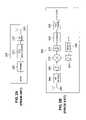
- FIGS. 2A and 2Billustrate conventional transmitter 200 and conventional receiver 250 for use in a prior art wireless access network that implements single carrier frequency domain equalization (SC-DFE).
- SC-DFEsingle carrier frequency domain equalization
- Transmitter 200comprises frame unit 205 , forward error correction-interleave unit 210 , RF modulator 215 , and antenna 220 .
- Frame unit 205receives an incoming data stream in the transmit path and formats the incoming data into data frames for burst transmissions.
- Forward error correction-interleave unit 210applies error correction codes and interleaves the data frame with N 1 other outgoing data frames.
- the interleaved baseband datais then up-converted by RF modulator 215 to a single RF carrier frequency and transmitted via antenna 220 to receiver 250 .
- Receiver 250comprises a receive path and a feedback path.
- the receive pathcomprises antenna 255 , RF demodulator 260 , N Fast Fourier Transform (FFT) processors 265 , mixer 270 , N Inverse Fourier Transform (IFFT) processors 275 , demodulator 280 , and forward error correction (FEC)-frame processing block 285 .
- the feedback pathcomprises weight update processor 290 and N Fast Fourier Transform (FFT) processors 295 .
- FIGS. 3A and 3Billustrate conventional transmitter 300 and conventional receiver 350 for use in a prior art wireless access network that implements orthogonal frequency domain multiplexing (OFDM) modulation.
- Transmitter 300comprises frame unit 305 , forward error correction-interleave unit 310 , N-channel modulator 315 , cyclic extensions unit 320 , N IFFT processors 325 and antenna 330 .
- Frame unit 305receives an incoming data stream in the transmit path and formats the incoming data into data frames for burst transmissions.
- Forward error correction-interleave unit 310applies error correction codes and interleaves the data frame with N ⁇ 1 other outgoing data frames. The data frames are then modulated onto N subchannels by N-channel modulator 315 .
- Cyclic extension unit 320adds to each subchannel a guard space having the same length, L, as the channel impulse response to avoid intersymbol interference caused by the physical channel.
- the modulated bitstreamis then passed through N IFFT processors 325 , which superimposes the modulated signal onto a series of subcarriers, and is transmitted via antenna 330 to receiver 350 .
- Receiver 350also comprises a receive path and a feedback path.
- the receive pathcomprises antenna 351 , N Fast Fourier Transform (FFT) processors 355 , mixer 360 , N channel demodulators 365 , and forward error correction (FEC)/frame processing block 370 .
- the feedback pathcomprises channel gain controller 375 .
- OFDM and single carrier-frequency domain equalizationare in reality duals of each other.
- An OFDM systemessentially moves the initial FFT of a SC-FDE system from the transmitter to the receiver. Both systems implement weight multiplication of the individual bits.
- One differenceis the use of N FFT processors 295 in the SC-FDE system to convert the time domain taps.
- the computational load of this functioncan be greatly reduced as the maximum channel Doppler spread (rate of the change of the channel) is less than 2 Hz.
- the air interfacecan perform a decimated update in which the tap update if performed one time in N bursts. Typically, it is necessary to update at least 10 times the rate of change of the channel. This would set a minimum update rate of 50 millisecond (1/(10 ⁇ 2 Hz)). Given a 2 millisecond time division duplex (TDD) frame rate, updates may be limited to once every 25 frames. In practice, the transceiver base station to subscriber link may be updated at between 2 and 10 milliseconds based on reception of the start of frame message.
- FIG. 4illustrates burst mode processing equalizer-demodulator 400 for use in RF modem shelf 140 of transceiver base station 110 according to one embodiment of the present invention.
- Equalizer-demodulator 400comprises low noise amplifier 402 , which receives and amplifies the incoming signals from the transmitters at the subscribers premises.
- the amplified RF signalis down-converted to a first intermediate frequency (IF 1 ) signal by radio frequency (RF) mixer 404 and RF local oscillator (LO) 406 .
- Bandpass filter (BPF) 408isolates the frequencies of interest in the IF 1 signal.
- the filtered IF 1 signalis down-converted again to a second intermediate frequency (IF 2 ) signal by IF mixer 410 and IF local oscillator 412 .
- the IF 2 signal at the output of IF mixer 410is further filtered by bandpass filter 414 to isolate the frequencies of interest.
- Analog programmable gain amplifier (PGA) 416scales the amplitude of the filtered IF 2 signal to match the dynamic range of analog-to-digital converter (ADC) 418 .
- ADC 418converts the amplified IF 2 signal to a sequence of digital samples that are amplified by digital programmable amplifier (PGA) 420 .
- the output of ADC 418 and digital PGA 420are sampled and analyzed by automatic gain control (AGC) algorithm (ALG) processor 422 , which produces a first (analog) gain factor, g 1 , that adjusts the gain (scale factor) of analog PGA 416 and a second (digital) gain factor, g 2 , that adjusts the gain of digital PGA 420 .
- ADCautomatic gain control
- AAGautomatic gain control
- the sample rate and phase of ADC 418are controller by sample clock 424 .
- NCONumerically controlled oscillator
- LPFLow pass filter
- the I and Q signalscomprise the input signal, Y K , that is applied to fractionally-spaced (2/T) feedforward (FF) equalization filters 440 .
- Feedforward equalization filters 440comprises an even FF filter and an odd FF filter that are implemented as a single frequency domain block filter using a Fast Fourier Transform (FFT).
- Feedforward equalization filter 440produces the complex output components, Z 1 and Z 2 , which are combined by summer 450 to produce the slicer input signal, Z K .
- Slicer 452quantizes the signal levels in the Z K signal to recover the sequence of symbols, X′ K .
- the X′ K symbol sequenceis further processed to recover the bits and words in the original data stream.
- Timing-phase recover algorithm processor 456sparse (1/T) post decision feedback (FB) rake filter 458 , fast channel estimation processor 460 , and preamble channel estimation and phase rotation processor 442 .
- Post-decision feedback rake filter 458operates in the time domain using a sparsely populated coefficient vector to minimize computation without sacrificing the ability to compensate for large multipath delays.
- the air interface of equalizer-demodulator 400uses time division duplex (TDD) bursts that support FFT block-size preambles.
- the preamblescomprises constant amplitude zero auto-correlation (CAZAC) phase shift keying (PSK) training sequences.
- CAZACconstant amplitude zero auto-correlation
- PSKphase shift keying
- the preamble, Pneed not be sent with every subscriber uplink data burst, but only as requested by the media access control (MAC) layer of transceiver base station 110 .
- the MAC layer of transceiver base station 110uses the uplink map field in the downlink header which commands the subscriber transceiver to transmit the uplink data burst.
- the request sent by the MAC layeris based on the channel estimation accuracy and fade tracking requirements.
- the raw channel estimationi.e., channel snapshot, h ss
- Cross-correlationis performed using an FFT algorithm.
- the received data vector, R, used by the MAC layeris optionally a block average (or a lossy average) of raw data vectors received during the preamble.
- transceiver base station 110sends the CAZAK PSK preamble at the start of every data burst.
- the snapshot channel estimates, h ssfrom the MAC layer are used to compute the high fidelity (noise reduced) channel estimate, h hifl , using a channel tap signal-to-noise (SNR) approximation to the ideal Wiener channel estimation filter.
- SNRchannel tap signal-to-noise
- Preamble channel estimation and phase rotation processor 442processes each CAZAK PSK preamble to estimate the carrier phase rotation, ⁇ C , from the beginning to the end of the preamble and uses this estimate to compute the carrier frequency offset, ⁇ F C , for feedback control of numerically controlled oscillator (NCO) algorithm block 434 .
- NCO algorithm block 434establishes the baseband in-phase and quadrature (I and Q) signals. NCO algorithm block 434 is gradually adjusted based on the ⁇ F C estimate to remove the carrier frequency offset.
- ⁇ F C⁇ C /(2 ⁇ TDP ), where TDP is the time duration of the preamble.
- ⁇ Cmin(arg(sum (P*R)).
- the present inventionemploys binary FFT length 2/T fractionally spaced feedforward filters.
- the filterare 16 symbols in duration, which is a computationally efficient length that provides robust channel matching capability.
- the filtersprovide 2/T fractionally spaced feedforward filtering for 16 symbol blocks using a radix 4 64 point complex FFT.
- the high fidelity channel estimate, h hifl , the ⁇ F C estimate and the ⁇ S estimate from preamble channel estimation and phase rotation processor 442are used to compute the coefficients (W) of feedforward equalization filter 440 and the coefficients (b) of post-decision feedback rake filter 458 using a computationally efficient algorithm.
- Post-decision feedback rake filter 458is a time domain filter employing a much longer delay line (N delay taps) than the number of feedback coefficients actually used. This design is similar to that of a rake receiver and allows the delay spread that can be covered to be conservative (e.g., 16+N delay taps+1 symbols)
- Equalizer-demodulator 400provides the required high performance demodulation of burst transmissions in multiple dynamic multipath environments. The channel estimates are retained and updated consistent with the cyclo-stationary operation of the TDD frame. Ideally, equalizer-demodulator 400 is coupled with the structure of the TDD air interface of the wireless communications system. The air interface specifies that all subscriber transmission bursts have durations (i.e., number of symbols) equal to an integer number of FFT blocks. In an advantageous embodiment, equalizer-demodulator 400 is coupled with the air interface such that the TDD bursts support FFT block size preambles. The inclusion of the preamble in the subscriber uplink is optional and under the command of the base station. This allows equalizer-demodulator 400 in transceiver base station 110 to track the multipath channels of individual subscribers while minimizing the preamble overhead.
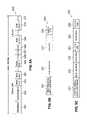
- FIG. 5Aillustrates exemplary time division duplex (TDD) frame 500 according to one embodiment of the present invention.
- FIG. 5Billustrates exemplary transmission burst 520 containing a frame with a single FEC block according to one embodiment of the present invention.
- FIG. 5Cillustrates exemplary transmission burst 530 containing a frame with multiple FEC blocks according to one embodiment of the present invention.
- TDDtime division duplex
- TDD frame 500comprises a downlink portion containing preamble field 501 , management field 502 , and N modulation groups, including modulation group 503 (labeled Modulation Group 1 ), modulation group 504 (labeled Modulation Group 2 ), and modulation group 505 (labeled Modulation Group N).
- modulation group 503labeled Modulation Group 1
- modulation group 504labeled Modulation Group 2
- modulation group 505labeled Modulation Group N
- TDD frame 500also comprises an uplink portion containing transmitter-transmitter guard (TTG) slot 506 , 0 to N registration (REG) minislots 507 , 1 to N contention (CON) request minislots 508 , N sub-burst slots, including sub-burst slot 509 (labeled Sub-Burst 1) and sub-burst slot 510 (labeled Sub-Burst N), and receiver-transmitter guard (RTG) slot 511 .
- TTGtransmitter-transmitter guard
- REGregistration
- CONcontention
- sub-burst slotsincluding sub-burst slot 509 (labeled Sub-Burst 1) and sub-burst slot 510 (labeled Sub-Burst N), and receiver-transmitter guard (RTG) slot 511 .
- RTGreceiver-transmitter guard
- Transmission burst 520comprises physical media dependent (PMD) preamble field 521 , MAC header field 522 , data packet data unit (PDU) field 523 , and block character redundancy check (CRC) field 524 .
- Transmission burst 530comprises physical media dependent (PMD) preamble field 531 , MAC header field 532 , data PDU field 533 , block CRC field 534 , data PDU field 535 , block CRC field 536 .
- the start of every frameincludes a Start-Of-Frame (SOF) field and a PHY Media Dependent Convergence (PMD) field.
- PMD preamblesare used to assist in synchronization and time-frequency recovery at the receiver.
- the SOF fieldallows subscribers using fixed diversity to test reception conditions of the two diversity antennas.
- the SOF PMD fieldis 32 symbols long and consists of two back-to-back 16-bit pseudorandom noise (PN) code sequences that are transmitted at 0 degree and 180 degree phase transitions.
- the SOF fieldis followed by downlink management messages broadcast from the base station to all subscribers using the lowest modulation or FEC index and orthogonal expansion. Management messages are transmitted both periodically (N times per hyperframe) and as required to change parameters or allocate parameters. Management messages include:
- DownLink Mapindicating the physical slot (PS) where downstream modulation changes (transmitted every frame);
- UpLink MAPindicating uplink subscriber access grants and associated physical slot start of the grant (transmitted when changed and at a minimum of one second hyperframe periods (shorter periods are optional));
- TDD frame and physical layer attributesperiodic at a minimum of one second hyperframe period
- the downlink management messagesare followed by multi-cast and uni-cast bursts arranged in increasing modulation complexity order.
- the present inventionintroduces the term “modulation group” to define a set of downstream bursts with the same modulation and FEC protection.
- a subscribercontinuously receives all the downstream data in the TDD frame downlink until the last symbol of the highest modulation group supported by the link is received. This allows a subscriber maximum time to perform receive demodulation updates.
- the downlink-to-uplink transitionprovides a guard time (TTG) to allow for propagation delays for all the subscribers.
- TTG position and durationis fully programmable and set by management physical layer attribute messages.
- the TTGis followed by a set of allocated contention slots that are subdivided between acquisition uplink ranging mini-slots and demand access request mini-slots.
- the Uplink MAP messageestablishes the number and location of each type of slot. Ranging slots are used for both initial uplink synchronization of subscribers performing net entry and for periodic update of synchronization of active subscribers.
- Contention slotsprovide a demand access request mechanism to establish subscriber service for a single traffic service flow. As collisions are possible, the subscriber uses random back-off, in integer TDD frame periods and retries based on a time out for request of service. Contention slots use the lowest possible modulation, FEC, and orthogonal expansion supported by the base station.
- the contention slotsare followed by individual subscriber transmissions (sub-bursts) that have been scheduled and allocated by the base station in the uplink MAP. Each subscriber transmission burst is performed at the maximum modulation, FEC, and orthogonal expansion supported by the subscriber. Finally, the subscriber transmissions are followed by the uplink-to-downlink transition which provides a guard time (RTG) to allow for propagation delays for all the subscribers.
- RTG durationis fully programmable and set by management physical layer attribute messages.
- the Physical Media Dependent (PMD) burst synchronizationis not used.
- the transmission burstbegins with the MAC header and is followed by the packet data unit (PDU) and the associated block CRC field that protects both the PDU and the header.
- PDUpacket data unit
- the PDUmay be a complete packet transmission or a fragment of a much larger message.
- the PDUmay be broken into segments that are protected by separate FEC CRC fields. This avoids wasting bandwidth with additional MAC headers.
- the PMD preamble length and patterncan be programmed by transceiver base station 110 .
- the preambleprovides a synchronization method for the base station receiver. Uplink registration and ranging packet bursts use longer PMD preambles.
Landscapes
- Engineering & Computer Science (AREA)
- Computer Networks & Wireless Communication (AREA)
- Signal Processing (AREA)
- Mobile Radio Communication Systems (AREA)
- Time-Division Multiplex Systems (AREA)
Abstract
Description
- 1) Ser. No. 09/713,684, filed on Nov. 15, 2000, entitled “SUBSCRIBER INTEGRATED ACCESS DEVICE FOR USE IN WIIRELESS AND WIRELINE ACCESS SYSTEMS;”
- 2) Ser. No. 09/839,726, filed Apr. 20, 2001, entitled “APPARATUS AND ASSOCIATED METHOD FOR OPERATING UPON DATA SIGNALS RECEIVED AT A RECEIVING STATION OF A FIXED WIRELESS ACCESS COMMUNICATION SYSTEM”;
- 3) Ser. No. 09/839,729, filed Apr. 20, 2001, entitled “APPARATUS AND METHOD FOR OPERATING A SUBSCRIBER INTERFACE IN A FIXED WIRELESS SYSTEM”;
- 4) Ser. No. 09/839,719, filed Apr. 20, 2001, entitled “APPARATUS AND METHOD FOR CREATING SIGNAL AND PROFILES AT A RECEIVING STATION”;
- 5) Ser. No. 09/838,910, filed Apr. 20, 2001, entitled “SYSTEM AND METHOD FOR INTERFACE BETWEEN A SUBSCRIBER MODEM AND) SUBSCRIBER PREMISES INTERFACES”;
- 6) Ser. No. 09/839,509, filed Apr. 20, 2001, entitled “BACKPLANE ARCHITECTURE FOR USE IN WIRELESS AND WIRELINE ACCESS SYSTEMS”;
- 7) Ser. No. 09/839,514, filed Apr. 20, 2001, entitled “SYSTEM AND METHOD FOR ON-LINE INSERTION OF LINE REPLACEABLE UNITS IN WIRELESS AND WIRELINE ACCESS SYSTEMS”;
- 8) Ser. No. 09/839,512, filed Apr. 20, 2001, entitled “SYSTEM FOR COORDINATION OF TDD TRANSMISSION BURSTS WITHIN AND BETWEEN CELLS IN A WIRELESS ACCESS SYSTEM AND METHOD OF OPERATION”;
- 9) Ser. No. 09/839,259, filed Apr. 20, 2001, entitled “REDUNDANT TELECOMMUNICATION SYSTEM USING MEMORY EQUALIZATION APPARATUS AND METHOD OF OPERATION”;
- 10) Ser. No. 09/839,457, filed Apr. 20, 2001, entitled “WIRELESS ACCESS SYSTEM FOR ALLOCATING AND SYNCHRONIZING UPLINIC AM) DOWNLINK OF TDD FRAMES AND METHOD OF OPERATION”;
- 11) Ser. No. 09/839,075, filed Apr. 20, 2001, entitled “TDD FDD AIR INTERFACE”;
- 12) Ser. No. 09/839,499, filed Apr. 20, 2001, entitled “APPARATUS, AND AN ASSOCIATED METHOD, FOR PROVIDING WLAN SERVICE IN A FIXED WIRELESS ACCESS COMMUNICATION SYSTEM”;
- 13) Ser. No. 09/839,458, filed Apr. 20, 2001, entitled “WIRELESS ACCESS SYSTEM USING MULTIPLE MODULATION”;
- 14) Ser. No. 09/839,456, filed Apr. 20, 2001, entitled “WIRELESS ACCESS SYSTEM AND ASSOCIATED METHOD USING MULTIPLE MODULATION FORMATS IN TDD FRAMES ACCORDING TO SUBSCRIBER SERVICE TYPE”;
- 15) Ser. No. 09/838,924, filed Apr. 20, 2001, entitled “APPARATUS FOR ESTABLISHING A PRIORITY CALL IN A FIXED WIRELESS ACCESS COMMUNICATION SYSTEM;
- 16) Ser. No. 09/839,727, filed Apr. 20, 2001, entitled “APPARATUS FOR REALLOCATING COMMUNICATION RESOURCES TO ESTABLISH A PRIORITY CALL IN A FIXED WIRELESS ACCESS COMMUNICATION SYSTEM”;
- 17) Ser. No. 09/839,734, filed Apr. 20, 2001, entitled “METHOD FOR ESTABLISHING A PRIORITY CALL IN A FIXED WIRELESS ACCESS COMMUNICATION SYSTEM”;
- 18) Ser. No. 09/839,513, filed Apr. 20, 2001, entitled “SYSTEM AND METHOD FOR PROVIDING AN IMPROVED COMMON CONTROL BUS FOR USE IN ON-LINE INSERTION OF LINE REPLACEABLE UNITS IN WIRELESS AND WIRELINE ACCESS SYSTEMS”;
- 19) Ser. No. 60/262,825, filed on Jan. 19, 2001, entitled “APPARATUS AND ASSOCIATED METHOD FOR OPERATING UPON DATA SIGNALS RECEIVED AT A RECEIVING STATION OF A FIXED WIRELESS ACCESS COMMUNICATION SYSTEM”;
- 20) Ser. No. 60/262,698, filed on Jan. 19, 2001, entitled “APPARATUS AND METHOD FOR OPERATING A SUBSCRIBER INTERFACE IN A FIXED WIRELESS SYSTEM”;
- 21) Ser. No. 60/262,827, filed on Jan. 19, 2001, entitled “APPARATUS AND METHOD FOR CREATING SIGNAL AND PROFILES AT A RECEIVING STATION”;
- 22) Ser. No. 60/262,826, filed on Jan. 19, 2001, entitled “SYSTEM ANT) METHOD FOR INTERFACE BETWEEN A SUBSCRIBER MODEM AND SUBSCRIBER PREMISES INTERFACES”;
- 23) Ser. No. 60/262,951, filed on Jan. 19, 2001, entitled “BACKPLANE ARCHITECTURE FOR USE IN WIRELESS AND WIRELINE ACCESS SYSTEMS”;
- 24) Ser. No. 60/262,824, filed on Jan. 19, 2001, entitled “SYSTEM AND METHOD FOR ON-LINE INSERTION OF LINE REPLACEABLE UNITS IN WIRELESS AND WIRELINE ACCESS SYSTEMS”;
- 25) Ser. No. 60/263,101, filed on Jan. 19, 2001, entitled “SYSTEM FOR COORDINATION OF TDD TRANSMISSION BURSTS WITHIN AND BETWEEN CELLS IN A WIRELESS ACCESS SYSTEM AND METHOD OF OPERATION”;
- 26) Ser. No. 60/263,097, filed on Jan. 19, 2001, entitled “REDUNDANT TELECOMMUNICATION SYSTEM USING MEMORY EQUALIZATION APPARATUS AND METHOD OF OPERATION”;
- 27) Ser. No. 60/273,579, filed Mar. 5, 2001, entitled “WIRELESS ACCESS SYSTEM FOR ALLOCATING AND SYNCHRONIZING UPLINK AND DOWNLINK OF TDD FRAMES AND METHOD OF OPERATION”;
- 28) Ser. No. 60/262,955, filed Jan. 19, 2001, entitled “TDD FDD AIR INTERFACE”;
- 29) Ser. No. 60/262,708, filed on Jan. 19, 2001, entitled “APPARATUS, AND AN ASSOCIATED METHOD, FOR PROVIDING WLAN SERVICE IN A FIXED WIRELESS ACCESS COMMUNICATION SYSTEM”;
- 30) Ser. No. 60/273,689, filed Mar. 5, 2001, entitled “WIRELESS ACCESS SYSTEM USING MULTIPLE MODULATION”;
- 31) Ser. No. 60/273,757, filed Mar. 5, 2001, entitled “WIRELESS ACCESS SYSTEM AND ASSOCIATED METHOD USING MULTIPLE MODULATION FORMATS IN TDD FRAMES ACCORDING TO SUBSCRIBER SERVICE TYPE”;
- 32) Ser. No. 60/270,378, filed Feb. 21, 2001, entitled “APPARATUS FOR ESTABLISHING A PRIORITY CALL IN A FIXED WIRELESS ACCESS COMMUNICATION SYSTEM”;
- 33) Ser. No. 60/270,385, filed Feb. 21, 2001, entitled “APPARATUS FOR REALLOCATING COMMUNICATION RESOURCES TO ESTABLISH A PRIORITY CALL IN A FIXED WIRELESS ACCESS COMMUNICATION SYSTEM”; and
- 34) Ser. No. 60/270,430, filed Feb. 21, 2001, entitled “METHOD FOR ESTABLISHING A PRIORITY CALL IN A FIXED WIRELESS ACCESS COMMUNICATION SYSTEM”.
- a) ATM;
- b) Class 5 switch interfaces (domestic GR-303 and international V5.2);
- c) TCP/IP with quality-of-service QoS for voice over IP (VOIP) (i.e., RTP) and other H.323 media services; and
- d) Distribution of synchronization of network time out to the subscribers;
| TABLE 1 | ||||
| RMS Delay | RMS Delay | RMS Delay | ||
| Signal | Antenna | Spread Min. | Spread Max. | Spread Mean |
| Path | Type | (usec.) | (usec.) | (usec.) |
| LOS | Direct. | 0.02 | 0.04 | 0.02 |
| LOS | Omni | 0.02 | 2.39 | 0.13 |
| Non-LOS | Direct. | 0.02 | 5.26 | 0.14 |
| Non-LOS | Omni | 0.02 | 7.06 | 0.37 |
- 1. Yields high efficiency in terms of computational complexity.
- 2. Provides rapid channel estimation.
- 3. Provides required equalization of multipath channel.
- 4. May be adapted to any form of modulation. It is a general and powerful technique with wide application.
- 5. May be extended to include multiple antenna-multiple receiver channel architectures by including antenna combining weights as part of the cyclo-stationary channel descriptor.
| TABLE 2 | |||
| FFT | Complexity Ratio | ||
| Size (N) | (FFT/Time Domain) | ||
| 32 | 1.2 | ||
| 64 | 0.69 | ||
| 128 | 0.38 | ||
| 256 | 0.21 | ||
| 512 | 0.12 | ||
ΔFC=ΦC/(2Π×TDP),
where TDP is the time duration of the preamble. Furthermore, in an advantageous embodiment of the present invention:
ΦC=min(arg(sum (P*R)).
Claims (18)
Applications Claiming Priority (2)
| Application Number | Priority Date | Filing Date | Title |
|---|---|---|---|
| US26271201P | 2001-01-19 | 2001-01-19 | |
| US09/838,810US20020086707A1 (en) | 2000-11-15 | 2001-04-20 | Wireless communication system using block filtering and fast equalization-demodulation and method of operation |
Publications (1)
| Publication Number | Publication Date |
|---|---|
| US7075967B2true US7075967B2 (en) | 2006-07-11 |
Family
ID=26949408
Family Applications (2)
| Application Number | Title | Priority Date | Filing Date |
|---|---|---|---|
| US09/838,810Expired - LifetimeUS7075967B2 (en) | 2001-01-19 | 2001-04-20 | Wireless communication system using block filtering and fast equalization-demodulation and method of operation |
| US09/838,810GrantedUS20020086707A1 (en) | 2000-11-15 | 2001-04-20 | Wireless communication system using block filtering and fast equalization-demodulation and method of operation |
Family Applications After (1)
| Application Number | Title | Priority Date | Filing Date |
|---|---|---|---|
| US09/838,810GrantedUS20020086707A1 (en) | 2000-11-15 | 2001-04-20 | Wireless communication system using block filtering and fast equalization-demodulation and method of operation |
Country Status (3)
| Country | Link |
|---|---|
| US (2) | US7075967B2 (en) |
| AU (1) | AU2002225270A1 (en) |
| WO (1) | WO2002058271A2 (en) |
Cited By (30)
| Publication number | Priority date | Publication date | Assignee | Title |
|---|---|---|---|---|
| US20030165157A1 (en)* | 2001-07-27 | 2003-09-04 | Stephen Pollmann | System and method for measuring signal to noise values in an adaptive wireless communication system |
| US20050152463A1 (en)* | 2002-02-21 | 2005-07-14 | Paul Dechamps | I/q mismatch compensation in an ofdm receiver in presence of frequency offset |
| US20050281323A1 (en)* | 2004-06-22 | 2005-12-22 | Laurence Mailaender | Method of receiver processing of CDMA signals in a CDMA system |
| US20060063483A1 (en)* | 2004-07-23 | 2006-03-23 | Sharp Kabushiki Kaisha | Radio receiver, radio communication system and electronic equipment |
| US7212569B1 (en)* | 2002-06-28 | 2007-05-01 | At&T Corp. | Frequency domain decision feedback equalizer |
| US20070194959A1 (en)* | 2006-02-03 | 2007-08-23 | Reinhard Rueckriem | Receiving method with digital level adjustment in the analog section and incremental level change in the digital section |
| US20070248173A1 (en)* | 2006-04-25 | 2007-10-25 | Microsoft Corporation | OFDMA based on cognitive radio |
| US20070263653A1 (en)* | 2006-05-12 | 2007-11-15 | Microsoft Corporation | Stack signaling to application with lack of requested bandwidth |
| US20080137634A1 (en)* | 2006-12-12 | 2008-06-12 | Microsoft Corporation | Cognitive multi-user OFDM |
| WO2008069437A1 (en)* | 2006-12-05 | 2008-06-12 | Electronics And Telecommunications Research Institute | Apparatus and method for receiving orthogonal frequency division multiplexing-based digital signal |
| US20080240267A1 (en)* | 2007-03-30 | 2008-10-02 | Microsoft Corporation | FEC in cognitive multi-user OFDMA |
| US20080279291A1 (en)* | 2007-05-08 | 2008-11-13 | Microsoft Corporation | OFDM transmission and reception for non-OFDMA signals |
| US20090010346A1 (en)* | 2007-07-02 | 2009-01-08 | Legend Silicon Corp. | TDS-OFDMA Communication System |
| US20090060100A1 (en)* | 2005-04-25 | 2009-03-05 | Akihiko Nishio | Wireless communication apparatus and wireless communication method |
| US20100157960A1 (en)* | 2008-12-18 | 2010-06-24 | Microsoft Corporation | Wireless access point supporting control by multiple applications |
| US20110222617A1 (en)* | 2002-07-05 | 2011-09-15 | Interdigital Technology Corporation | Method for performing wireless switching |
| US8374130B2 (en) | 2008-01-25 | 2013-02-12 | Microsoft Corporation | Orthogonal frequency division multiple access with carrier sense |
| US20130177008A1 (en)* | 2005-01-06 | 2013-07-11 | Samsung Electronics Co., Ltd. | Method for Configuring Gain Factors for Uplink Service in Radio Telecommunication System |
| US9225555B2 (en) | 2000-11-15 | 2015-12-29 | Access Solutions, Ltd. | Wireless communication system and device for coupling a base station and mobile stations |
| US9426794B2 (en) | 2000-11-15 | 2016-08-23 | Access Solutions, Ltd. | Wireless communication system and device for coupling a base station and mobile stations |
| US9537682B2 (en)* | 2015-03-17 | 2017-01-03 | Intel Corporation | High speed receiver with one-hot decision feedback equalizer |
| US9928854B1 (en) | 2017-05-03 | 2018-03-27 | Seagate Technology Llc | MISO equalization with ADC averaging |
| US9954537B1 (en) | 2016-12-23 | 2018-04-24 | Seagate Technology Llc | Wide frequency range clock generation with phase interpolation |
| US9979573B1 (en) | 2016-12-23 | 2018-05-22 | Seagate Technology Llc | Position error signal burst demodulation |
| US9998136B1 (en) | 2017-02-17 | 2018-06-12 | Seagate Technology Llc | Loop consistency using multiple channel estimates |
| US10084553B1 (en) | 2016-12-22 | 2018-09-25 | Seagate Technology Llc | Iterative recovery from baseline or timing disturbances |
| US10152457B1 (en) | 2016-10-25 | 2018-12-11 | Seagate Technology Llc | Target parameter adaptation |
| US10164760B1 (en) | 2016-10-18 | 2018-12-25 | Seagate Technology Llc | Timing excursion recovery |
| US10277718B1 (en) | 2016-11-22 | 2019-04-30 | Seagate Technology Llc | Preamble defect detection and mitigation |
| US10382166B1 (en) | 2017-02-22 | 2019-08-13 | Seagate Technology Llc | Constrained receiver parameter optimization |
Families Citing this family (56)
| Publication number | Priority date | Publication date | Assignee | Title |
|---|---|---|---|---|
| EP1821480B1 (en) | 2000-08-24 | 2009-10-21 | Sony Deutschland Gmbh | Communication device for receiving and transmitting OFDM signals in a wireless communication system |
| WO2002023842A1 (en)* | 2000-09-11 | 2002-03-21 | Fox Digital | Apparatus and method for using adaptive algorithms to exploit sparsity in target weight vectors in an adaptive channel equalizer |
| AU2002235258A1 (en)* | 2000-12-27 | 2002-07-08 | Ensemble Communications, Inc. | Adaptive call admission control for use in a wireless communication system |
| US20020131514A1 (en)* | 2001-03-13 | 2002-09-19 | Ng Jason Wee Peng | Waveform diversity for communication using pulse decoding |
| US6831957B2 (en)* | 2001-03-14 | 2004-12-14 | Texas Instruments Incorporated | System and method of dual mode automatic gain control for a digital radio receiver |
| US7379508B1 (en)* | 2001-04-09 | 2008-05-27 | At&T Corp. | Frequency-domain method for joint equalization and decoding of space-time block codes |
| US7092450B1 (en)* | 2001-04-09 | 2006-08-15 | At&T Corp. | Frequency-domain method for joint equalization and decoding of space-time block codes |
| US7042937B2 (en)* | 2001-04-23 | 2006-05-09 | Koninklijke Philips Electronics N.V. | Hybrid frequency-time domain equalizer |
| US20030039226A1 (en)* | 2001-08-24 | 2003-02-27 | Kwak Joseph A. | Physical layer automatic repeat request (ARQ) |
| WO2003026297A1 (en)* | 2001-09-12 | 2003-03-27 | Samsung Electronics Co., Ltd. | Method and apparatus for transferring channel information in ofdm communications |
| GB2384394A (en)* | 2002-01-18 | 2003-07-23 | Inmarsat Ltd | Adapting transmission parameters to link conditions |
| AU2003903826A0 (en)* | 2003-07-24 | 2003-08-07 | University Of South Australia | An ofdm receiver structure |
| US7336902B1 (en)* | 2002-06-06 | 2008-02-26 | At&T Corp. | Integrated electro-optic hybrid communication system |
| US6922560B1 (en)* | 2002-08-20 | 2005-07-26 | National Semiconductor Corporation | Method and system for antenna verification for closed loop transmit diversity |
| US20040047368A1 (en)* | 2002-08-28 | 2004-03-11 | Xu Jin Biao | Frame synchronization for OFDM systems |
| KR100448633B1 (en)* | 2002-10-22 | 2004-09-13 | 한국전자통신연구원 | Residual freqency offset tracking scheme for single carrier - freuqency domian equalizer system and method thereof |
| KR100542090B1 (en)* | 2002-12-16 | 2006-01-11 | 한국전자통신연구원 | Error control method, wireless access control frame design method, terminal registration method and recording medium in wireless communication system |
| DE10341546A1 (en)* | 2003-09-09 | 2005-01-05 | Siemens Ag | Transmitting data to receiver device involves transmitting at least one individual pilot sequence via transmission signals over radio interface for channel estimation using CAZAC codes |
| WO2006015108A2 (en)* | 2004-07-27 | 2006-02-09 | Zte San Diego, Inc. | Transmission and reception of reference preamble signals in ofdma or ofdm communication systems |
| US7852746B2 (en)* | 2004-08-25 | 2010-12-14 | Qualcomm Incorporated | Transmission of signaling in an OFDM-based system |
| US7327803B2 (en) | 2004-10-22 | 2008-02-05 | Parkervision, Inc. | Systems and methods for vector power amplification |
| US7355470B2 (en) | 2006-04-24 | 2008-04-08 | Parkervision, Inc. | Systems and methods of RF power transmission, modulation, and amplification, including embodiments for amplifier class transitioning |
| WO2006062428A1 (en)* | 2004-11-29 | 2006-06-15 | Intel Corporation | Method and system for multicarrier communication between a base station and subscribers of different bandwidths |
| KR100810290B1 (en)* | 2004-12-14 | 2008-03-07 | 삼성전자주식회사 | Method and system for allocation data burst in a wireless communication system |
| US8040831B2 (en)* | 2005-03-04 | 2011-10-18 | Cisco Technology, Inc. | Method and system for control channel beamforming |
| KR100868679B1 (en)* | 2005-06-01 | 2008-11-13 | 삼성전자주식회사 | Preamble signal transmission and reception apparatus and method in a wireless communication system |
| US7911272B2 (en) | 2007-06-19 | 2011-03-22 | Parkervision, Inc. | Systems and methods of RF power transmission, modulation, and amplification, including blended control embodiments |
| US9106316B2 (en) | 2005-10-24 | 2015-08-11 | Parkervision, Inc. | Systems and methods of RF power transmission, modulation, and amplification |
| US8334722B2 (en) | 2007-06-28 | 2012-12-18 | Parkervision, Inc. | Systems and methods of RF power transmission, modulation and amplification |
| US20130078934A1 (en) | 2011-04-08 | 2013-03-28 | Gregory Rawlins | Systems and Methods of RF Power Transmission, Modulation, and Amplification |
| KR100943613B1 (en)* | 2005-11-22 | 2010-02-24 | 삼성전자주식회사 | Apparatus and method for uplink scheduling in a communication system |
| KR100878176B1 (en)* | 2005-12-10 | 2009-01-12 | 삼성전자주식회사 | Apparatus and method for adjusting the operation switching gap in a multi-hop relay cellular network |
| US8031804B2 (en)* | 2006-04-24 | 2011-10-04 | Parkervision, Inc. | Systems and methods of RF tower transmission, modulation, and amplification, including embodiments for compensating for waveform distortion |
| US8457039B2 (en)* | 2006-10-24 | 2013-06-04 | Texas Instruments Incorporated | Random access channel design with hybrid CDM and FDM multiplexing of access |
| US7729463B2 (en)* | 2006-12-22 | 2010-06-01 | Newport Media, Inc. | Host processor assisted fast re-synchronization techniques for DVB-H systems |
| US7729462B2 (en)* | 2006-12-22 | 2010-06-01 | Newport Media, Inc. | Fast re-synchronization techniques for DVB-H systems |
| US8238436B2 (en)* | 2007-03-30 | 2012-08-07 | Mediatek Inc. | Methods and device for fast acquisition of digital video signals |
| WO2008144017A1 (en) | 2007-05-18 | 2008-11-27 | Parkervision, Inc. | Systems and methods of rf power transmission, modulation, and amplification |
| WO2008156800A1 (en) | 2007-06-19 | 2008-12-24 | Parkervision, Inc. | Combiner-less multiple input single output (miso) amplification with blended control |
| US8411766B2 (en)* | 2008-04-09 | 2013-04-02 | Wi-Lan, Inc. | System and method for utilizing spectral resources in wireless communications |
| WO2010021739A1 (en)* | 2008-08-21 | 2010-02-25 | Ikanos Communications, Inc. | Method and apparatus for a data transmission in home networks |
| US8274885B2 (en)* | 2008-10-03 | 2012-09-25 | Wi-Lan, Inc. | System and method for data distribution in VHF/UHF bands |
| US8107391B2 (en)* | 2008-11-19 | 2012-01-31 | Wi-Lan, Inc. | Systems and etiquette for home gateways using white space |
| US8335204B2 (en) | 2009-01-30 | 2012-12-18 | Wi-Lan, Inc. | Wireless local area network using TV white space spectrum and long term evolution system architecture |
| US20100309317A1 (en)* | 2009-06-04 | 2010-12-09 | Wi-Lan Inc. | Device and method for detecting unused tv spectrum for wireless communication systems |
| US8937872B2 (en)* | 2009-06-08 | 2015-01-20 | Wi-Lan, Inc. | Peer-to-peer control network for a wireless radio access network |
| KR20140034895A (en) | 2011-06-02 | 2014-03-20 | 파커비전, 인크. | Antenna control |
| EP2584849B1 (en)* | 2011-10-17 | 2019-02-27 | Commissariat à l'Énergie Atomique et aux Énergies Alternatives | Method for node positioning for a wireless network |
| US9414372B2 (en)* | 2012-03-16 | 2016-08-09 | Qualcomm Incorporated | Digital filter control for filter tracking speedup |
| US9906333B2 (en) | 2012-08-13 | 2018-02-27 | Microsoft Technology Licensing, Llc | In-frame acknowledgments and retransmissions |
| CN106415435B (en) | 2013-09-17 | 2020-08-11 | 帕克维辛股份有限公司 | Method, apparatus, and system for presenting information-carrying time functions |
| TWI575901B (en)* | 2015-06-17 | 2017-03-21 | 晨星半導體股份有限公司 | Device and method for eliminating channel effect |
| US9819456B1 (en)* | 2016-10-17 | 2017-11-14 | Seagate Technology Llc | Preamble detection and frequency offset determination |
| CN110113723B (en)* | 2019-05-07 | 2020-02-11 | 中国民航大学 | Method for measuring and estimating environmental parameters in airplane cabin based on wireless sensor network |
| CN118556373A (en)* | 2022-01-17 | 2024-08-27 | 诺基亚通信公司 | Complexity reduction of an open radio access network radio unit uplink receiver |
| CN116304624B (en)* | 2023-02-27 | 2024-01-30 | 之江实验室 | Fast radio burst search method based on slope detection and curve fitting achromatic dispersion |
Citations (17)
| Publication number | Priority date | Publication date | Assignee | Title |
|---|---|---|---|---|
| GB2302777A (en) | 1995-06-27 | 1997-01-29 | Motorola Israel Ltd | Recovering symbols of a digitally modulated radio signal |
| WO1997009781A1 (en) | 1995-09-08 | 1997-03-13 | France Telecom | Decision feedback filter device in the frequency domain |
| US5638371A (en) | 1995-06-27 | 1997-06-10 | Nec Usa, Inc. | Multiservices medium access control protocol for wireless ATM system |
| US5684791A (en) | 1995-11-07 | 1997-11-04 | Nec Usa, Inc. | Data link control protocols for wireless ATM access channels |
| US5694424A (en) | 1996-03-15 | 1997-12-02 | Ariyavisitakul; Sirikiat | Pre-cancelling postcursors in decision feedback equalization |
| WO1998004073A2 (en)* | 1996-07-19 | 1998-01-29 | Libit Signal Processing Limited | Blind dfe and phase correction |
| US5809086A (en) | 1996-03-20 | 1998-09-15 | Lucent Technologies Inc. | Intelligent timing recovery for a broadband adaptive equalizer |
| US5815529A (en)* | 1996-04-04 | 1998-09-29 | Lucent Technologies Inc. | Transmission system for digital audio broadcasting that incorporates a rotator in the transmitter |
| US5835526A (en)* | 1992-10-12 | 1998-11-10 | Nokia Mobile Phones Ltd. | Channel equalizer for a telecommunication system |
| US5991308A (en)* | 1995-08-25 | 1999-11-23 | Terayon Communication Systems, Inc. | Lower overhead method for data transmission using ATM and SCDMA over hybrid fiber coax cable plant |
| US5991292A (en) | 1997-03-06 | 1999-11-23 | Nortel Networks Corporation | Network access in multi-service environment |
| US6144697A (en)* | 1998-02-02 | 2000-11-07 | Purdue Research Foundation | Equalization techniques to reduce intersymbol interference |
| US6188873B1 (en) | 1996-12-09 | 2001-02-13 | Telia Ab | Broadband radio access method, device and system |
| US20020070796A1 (en) | 2000-10-17 | 2002-06-13 | Olivier Gay-Bellile | Multi-standard channel decoder |
| US6643321B1 (en)* | 1998-09-30 | 2003-11-04 | Alvarion Ltd. | Method for rapid synchronization of a point to multipoint communication system |
| US6650624B1 (en)* | 1998-10-30 | 2003-11-18 | Broadcom Corporation | Cable modem apparatus and method |
| US6661857B1 (en)* | 2000-07-10 | 2003-12-09 | Intersil Americas Inc. | Rapid estimation of wireless channel impulse response |
- 2001
- 2001-04-20USUS09/838,810patent/US7075967B2/ennot_activeExpired - Lifetime
- 2001-04-20USUS09/838,810patent/US20020086707A1/enactiveGranted
- 2002
- 2002-01-18AUAU2002225270Apatent/AU2002225270A1/ennot_activeAbandoned
- 2002-01-18WOPCT/IB2002/000137patent/WO2002058271A2/ennot_activeApplication Discontinuation
Patent Citations (17)
| Publication number | Priority date | Publication date | Assignee | Title |
|---|---|---|---|---|
| US5835526A (en)* | 1992-10-12 | 1998-11-10 | Nokia Mobile Phones Ltd. | Channel equalizer for a telecommunication system |
| US5638371A (en) | 1995-06-27 | 1997-06-10 | Nec Usa, Inc. | Multiservices medium access control protocol for wireless ATM system |
| GB2302777A (en) | 1995-06-27 | 1997-01-29 | Motorola Israel Ltd | Recovering symbols of a digitally modulated radio signal |
| US5991308A (en)* | 1995-08-25 | 1999-11-23 | Terayon Communication Systems, Inc. | Lower overhead method for data transmission using ATM and SCDMA over hybrid fiber coax cable plant |
| WO1997009781A1 (en) | 1995-09-08 | 1997-03-13 | France Telecom | Decision feedback filter device in the frequency domain |
| US5684791A (en) | 1995-11-07 | 1997-11-04 | Nec Usa, Inc. | Data link control protocols for wireless ATM access channels |
| US5694424A (en) | 1996-03-15 | 1997-12-02 | Ariyavisitakul; Sirikiat | Pre-cancelling postcursors in decision feedback equalization |
| US5809086A (en) | 1996-03-20 | 1998-09-15 | Lucent Technologies Inc. | Intelligent timing recovery for a broadband adaptive equalizer |
| US5815529A (en)* | 1996-04-04 | 1998-09-29 | Lucent Technologies Inc. | Transmission system for digital audio broadcasting that incorporates a rotator in the transmitter |
| WO1998004073A2 (en)* | 1996-07-19 | 1998-01-29 | Libit Signal Processing Limited | Blind dfe and phase correction |
| US6188873B1 (en) | 1996-12-09 | 2001-02-13 | Telia Ab | Broadband radio access method, device and system |
| US5991292A (en) | 1997-03-06 | 1999-11-23 | Nortel Networks Corporation | Network access in multi-service environment |
| US6144697A (en)* | 1998-02-02 | 2000-11-07 | Purdue Research Foundation | Equalization techniques to reduce intersymbol interference |
| US6643321B1 (en)* | 1998-09-30 | 2003-11-04 | Alvarion Ltd. | Method for rapid synchronization of a point to multipoint communication system |
| US6650624B1 (en)* | 1998-10-30 | 2003-11-18 | Broadcom Corporation | Cable modem apparatus and method |
| US6661857B1 (en)* | 2000-07-10 | 2003-12-09 | Intersil Americas Inc. | Rapid estimation of wireless channel impulse response |
| US20020070796A1 (en) | 2000-10-17 | 2002-06-13 | Olivier Gay-Bellile | Multi-standard channel decoder |
Non-Patent Citations (3)
| Title |
|---|
| Golberg, S., et al.; "Joint Carrier Recovery and Data Equalization Using Frequency Domain Techniques"; European Signal Processing Conference; Publication date Mar. 18, 1990; XP000365920; pp. 1823-1826. |
| Ready, M., et al.; "Architecture Considerations for Frequency Domain Adaptive Equalizers"; Asilomar Conference on Signals, Systems and Computers, Oct. 30, 1989; XP000217207; pp. 687-691. |
| Webster, M.; "Frequency-Domain Techniques for the Cyclostationary Signals Encountered in Fractionally-Spaced Equalizers"; IEEE International Conference on Acoustic, Speech and Signal Processing; Publication date Mar. 23, 1992; XP000467291; pp. 705-708. |
Cited By (67)
| Publication number | Priority date | Publication date | Assignee | Title |
|---|---|---|---|---|
| US9225555B2 (en) | 2000-11-15 | 2015-12-29 | Access Solutions, Ltd. | Wireless communication system and device for coupling a base station and mobile stations |
| US9426794B2 (en) | 2000-11-15 | 2016-08-23 | Access Solutions, Ltd. | Wireless communication system and device for coupling a base station and mobile stations |
| US9379916B2 (en) | 2001-01-19 | 2016-06-28 | Access Solutions, Ltd. | Wireless communication system and device for coupling a base station and mobile stations |
| US10264562B2 (en) | 2001-01-19 | 2019-04-16 | Access Solutions, Ltd. | TDD FDD communication interface |
| US20030165157A1 (en)* | 2001-07-27 | 2003-09-04 | Stephen Pollmann | System and method for measuring signal to noise values in an adaptive wireless communication system |
| US7577100B2 (en)* | 2001-07-27 | 2009-08-18 | Stephen Pollmann | System and method for measuring signal to noise values in an adaptive wireless communication system |
| US7443783B2 (en)* | 2002-02-21 | 2008-10-28 | Freescale Semiconductor, Inc. | I/Q mismatch compensation in an OFDM receiver in presence of frequency offset |
| US20050152463A1 (en)* | 2002-02-21 | 2005-07-14 | Paul Dechamps | I/q mismatch compensation in an ofdm receiver in presence of frequency offset |
| US7212569B1 (en)* | 2002-06-28 | 2007-05-01 | At&T Corp. | Frequency domain decision feedback equalizer |
| US7418035B1 (en)* | 2002-06-28 | 2008-08-26 | At&T Corp. | Frequency domain decision feedback equalizer |
| US10116421B2 (en) | 2002-07-05 | 2018-10-30 | Interdigital Technology Corporation | Method for performing wireless switching |
| US9712294B2 (en) | 2002-07-05 | 2017-07-18 | Interdigital Technology Corporation | Method for performing wireless switching |
| US20110222617A1 (en)* | 2002-07-05 | 2011-09-15 | Interdigital Technology Corporation | Method for performing wireless switching |
| US11171749B2 (en) | 2002-07-05 | 2021-11-09 | Interdigital Technology Corporation | Method for performing wireless switching |
| US8917660B2 (en)* | 2002-07-05 | 2014-12-23 | Interdigital Technology Corporation | Method for performing wireless switching |
| US7660340B2 (en)* | 2004-06-22 | 2010-02-09 | Alcatel-Lucent Usa Inc. | Method of receiver processing of CDMA signals in a CDMA system |
| US20050281323A1 (en)* | 2004-06-22 | 2005-12-22 | Laurence Mailaender | Method of receiver processing of CDMA signals in a CDMA system |
| US7392024B2 (en)* | 2004-07-23 | 2008-06-24 | Sharp Kabushiki Kaisha | Radio receiver, radio communication system and electronic equipment |
| US20060063483A1 (en)* | 2004-07-23 | 2006-03-23 | Sharp Kabushiki Kaisha | Radio receiver, radio communication system and electronic equipment |
| US20130177008A1 (en)* | 2005-01-06 | 2013-07-11 | Samsung Electronics Co., Ltd. | Method for Configuring Gain Factors for Uplink Service in Radio Telecommunication System |
| US8995924B2 (en)* | 2005-01-06 | 2015-03-31 | Samsung Electronics Co., Ltd. | Method for configuring gain factors for uplink service in radio telecommunication system |
| US20090060100A1 (en)* | 2005-04-25 | 2009-03-05 | Akihiko Nishio | Wireless communication apparatus and wireless communication method |
| US7920659B2 (en)* | 2005-04-25 | 2011-04-05 | Panasonic Corporation | Wireless communication apparatus and wireless communication method |
| US7492294B2 (en)* | 2006-02-03 | 2009-02-17 | Infineon Technologies Ag | Receiving method with digital level adjustment in the analog section and incremental level change in the digital section |
| US20070194959A1 (en)* | 2006-02-03 | 2007-08-23 | Reinhard Rueckriem | Receiving method with digital level adjustment in the analog section and incremental level change in the digital section |
| US7933344B2 (en) | 2006-04-25 | 2011-04-26 | Mircosoft Corporation | OFDMA based on cognitive radio |
| US20070248173A1 (en)* | 2006-04-25 | 2007-10-25 | Microsoft Corporation | OFDMA based on cognitive radio |
| US10182367B2 (en) | 2006-05-12 | 2019-01-15 | Microsoft Technology Licensing Llc | Signaling to application lack of requested bandwidth |
| US9386055B2 (en) | 2006-05-12 | 2016-07-05 | Microsoft Technology Licensing, Llc | Signaling to application lack of requested bandwidth |
| US8189621B2 (en) | 2006-05-12 | 2012-05-29 | Microsoft Corporation | Stack signaling to application with lack of requested bandwidth |
| US20070263653A1 (en)* | 2006-05-12 | 2007-11-15 | Microsoft Corporation | Stack signaling to application with lack of requested bandwidth |
| US8509265B2 (en) | 2006-05-12 | 2013-08-13 | Microsoft Corporation | Stack signaling to application with lack of requested bandwidth |
| US8923340B2 (en) | 2006-05-12 | 2014-12-30 | Microsoft Corporation | Signaling to application lack of requested bandwidth |
| WO2008069437A1 (en)* | 2006-12-05 | 2008-06-12 | Electronics And Telecommunications Research Institute | Apparatus and method for receiving orthogonal frequency division multiplexing-based digital signal |
| US9866418B2 (en) | 2006-12-12 | 2018-01-09 | Microsoft Technology Licensing, Llc | Cognitive multi-user OFDMA |
| US9641273B2 (en) | 2006-12-12 | 2017-05-02 | Microsoft Technology Licensing, Llc | Cognitive multi-user OFDMA |
| US9065687B2 (en) | 2006-12-12 | 2015-06-23 | Microsoft Technology Licensing, Llc | Cognitive multi-user OFDMA |
| US8144793B2 (en) | 2006-12-12 | 2012-03-27 | Microsoft Corporation | Cognitive multi-user OFDMA |
| US9774415B2 (en) | 2006-12-12 | 2017-09-26 | Microsoft Technology Licensing, Llc | Cognitive multi-user OFDMA |
| US10581655B2 (en) | 2006-12-12 | 2020-03-03 | Microsoft Technology Licensing, Llc | Cognitive multi-user OFDMA |
| US20080137634A1 (en)* | 2006-12-12 | 2008-06-12 | Microsoft Corporation | Cognitive multi-user OFDM |
| US8842752B2 (en) | 2007-03-30 | 2014-09-23 | Microsoft Corporation | FEC in cognitive multi-user OFDMA |
| US7929623B2 (en) | 2007-03-30 | 2011-04-19 | Microsoft Corporation | FEC in cognitive multi-user OFDMA |
| US20080240267A1 (en)* | 2007-03-30 | 2008-10-02 | Microsoft Corporation | FEC in cognitive multi-user OFDMA |
| US8718211B2 (en) | 2007-05-08 | 2014-05-06 | Microsoft Corporation | OFDM transmission and reception for non-OFDM signals |
| US9755879B2 (en) | 2007-05-08 | 2017-09-05 | Microsoft Technology Licensing, Llc | OFDM transmission and reception for non-OFDM signals |
| US9363120B2 (en) | 2007-05-08 | 2016-06-07 | Microsoft Technology Licensing, Llc | OFDM transmission and reception for non-OFDM signals |
| US20080279291A1 (en)* | 2007-05-08 | 2008-11-13 | Microsoft Corporation | OFDM transmission and reception for non-OFDMA signals |
| US7970085B2 (en) | 2007-05-08 | 2011-06-28 | Microsoft Corporation | OFDM transmission and reception for non-OFDMA signals |
| US10177953B2 (en) | 2007-05-08 | 2019-01-08 | Microsoft Technology Licensing, Llc | OFDM transmission and reception for non-OFDM signals |
| US20090010346A1 (en)* | 2007-07-02 | 2009-01-08 | Legend Silicon Corp. | TDS-OFDMA Communication System |
| US8374130B2 (en) | 2008-01-25 | 2013-02-12 | Microsoft Corporation | Orthogonal frequency division multiple access with carrier sense |
| US9363795B2 (en) | 2008-01-25 | 2016-06-07 | Microsoft Technology Licensing, Llc | Orthogonal Frequency Division Multiple Access with carrier sense |
| US9742529B2 (en) | 2008-01-25 | 2017-08-22 | Microsoft Technology Licensing, Llc | Orthogonal frequency division multiple access with carrier sense |
| US8855087B2 (en) | 2008-12-18 | 2014-10-07 | Microsoft Corporation | Wireless access point supporting control by multiple applications |
| US20100157960A1 (en)* | 2008-12-18 | 2010-06-24 | Microsoft Corporation | Wireless access point supporting control by multiple applications |
| US9537682B2 (en)* | 2015-03-17 | 2017-01-03 | Intel Corporation | High speed receiver with one-hot decision feedback equalizer |
| US10164760B1 (en) | 2016-10-18 | 2018-12-25 | Seagate Technology Llc | Timing excursion recovery |
| US10152457B1 (en) | 2016-10-25 | 2018-12-11 | Seagate Technology Llc | Target parameter adaptation |
| US10277718B1 (en) | 2016-11-22 | 2019-04-30 | Seagate Technology Llc | Preamble defect detection and mitigation |
| US10084553B1 (en) | 2016-12-22 | 2018-09-25 | Seagate Technology Llc | Iterative recovery from baseline or timing disturbances |
| US9979573B1 (en) | 2016-12-23 | 2018-05-22 | Seagate Technology Llc | Position error signal burst demodulation |
| US9954537B1 (en) | 2016-12-23 | 2018-04-24 | Seagate Technology Llc | Wide frequency range clock generation with phase interpolation |
| US9998136B1 (en) | 2017-02-17 | 2018-06-12 | Seagate Technology Llc | Loop consistency using multiple channel estimates |
| US10382166B1 (en) | 2017-02-22 | 2019-08-13 | Seagate Technology Llc | Constrained receiver parameter optimization |
| US10255931B1 (en) | 2017-05-03 | 2019-04-09 | Seagate Technology Llc | MISO equalization with ADC averaging |
| US9928854B1 (en) | 2017-05-03 | 2018-03-27 | Seagate Technology Llc | MISO equalization with ADC averaging |
Also Published As
| Publication number | Publication date |
|---|---|
| US20020086707A1 (en) | 2002-07-04 |
| WO2002058271A2 (en) | 2002-07-25 |
| AU2002225270A1 (en) | 2002-07-30 |
| WO2002058271A3 (en) | 2003-02-06 |
Similar Documents
| Publication | Publication Date | Title |
|---|---|---|
| US7075967B2 (en) | Wireless communication system using block filtering and fast equalization-demodulation and method of operation | |
| US7304939B2 (en) | Communication using simultaneous orthogonal signals | |
| US7230931B2 (en) | Wireless access system using selectively adaptable beam forming in TDD frames and method of operation | |
| US7573822B1 (en) | Broadband network for coaxial cable using multi-carrier modulation | |
| RU2255427C2 (en) | Orthogonal frequency division modulated stationary wireless regional network employing user's room equipment provided with indoor antenna | |
| US7173916B2 (en) | Wireless access system using multiple modulation formats in TDD frames and method of operation | |
| US20040052228A1 (en) | Method and system of frequency and time synchronization of a transceiver to signals received by the transceiver | |
| US20030012308A1 (en) | Adaptive channel estimation for wireless systems | |
| US20130028150A1 (en) | Method and System for Wireless Communication in Multiple Operating Environments | |
| EP1611723A1 (en) | Position adjusted guard time interval for ofdm-communications system | |
| WO2002071695A2 (en) | Wireless access using multiple modulation formats according to subscriber type | |
| EP0951763A2 (en) | Method for frequency division duplex communications | |
| US7099383B2 (en) | Apparatus and associated method for operating upon data signals received at a receiving station of a fixed wireless access communication system | |
| US20020098799A1 (en) | Apparatus and method for operating a subscriber interface in a fixed wireless system | |
| US6680932B1 (en) | Frequency and time synchronization in severe delay spread channels | |
| US6947477B2 (en) | Apparatus and method for creating signal and profiles at a receiving station | |
| CA2517483C (en) | Fixed ofdm wireless man utilizing cpe having internal antenna | |
| WO2002071694A2 (en) | Wireless access system for allocating and synchronizing tdd frames | |
| Eichinger et al. | ATM‐based wireless broadband access in the local loop | |
| Chheda | A Comparison Between Synchronous CDMA and Orthogonal Frequency Division Multiplexing (OFDM) for Fixed Broadband Wireless Access | |
| WO2002071693A2 (en) | Wireless access system using multiple modulation formats in tdd frames and method of operation | |
| WO2002058410A2 (en) | Apparatus and associated method for operating upon data signals received at a receiving station of a fixed wireless access communication system | |
| MXPA99007160A (en) | Method for frequency division duplex communications |
Legal Events
| Date | Code | Title | Description |
|---|---|---|---|
| AS | Assignment | Owner name:RAZE TECHNOLOGIES, INC., TEXAS Free format text:ASSIGNMENT OF ASSIGNORS INTEREST;ASSIGNORS:STRUHSAKER, PAUL F.;MCKOWN, RUSSELL C.;REEL/FRAME:011733/0519 Effective date:20010419 | |
| AS | Assignment | Owner name:ACCESS SOLUTIONS, LTD., TEXAS Free format text:ASSIGNMENT OF ASSIGNORS INTEREST;ASSIGNOR:RAZE TECHNOLOGIES, INC.;REEL/FRAME:012449/0730 Effective date:20011220 | |
| STCF | Information on status: patent grant | Free format text:PATENTED CASE | |
| REMI | Maintenance fee reminder mailed | ||
| FPAY | Fee payment | Year of fee payment:4 | |
| SULP | Surcharge for late payment | ||
| AS | Assignment | Owner name:MUNCK WILSON MANDALA, LLP, TEXAS Free format text:SECURITY AGREEMENT;ASSIGNOR:ACCESS SOLUTIONS, LTD.;REEL/FRAME:028332/0145 Effective date:20120328 | |
| REMI | Maintenance fee reminder mailed | ||
| FPAY | Fee payment | Year of fee payment:8 | |
| SULP | Surcharge for late payment | Year of fee payment:7 | |
| FEPP | Fee payment procedure | Free format text:MAINTENANCE FEE REMINDER MAILED (ORIGINAL EVENT CODE: REM.) | |
| FEPP | Fee payment procedure | Free format text:11.5 YR SURCHARGE- LATE PMT W/IN 6 MO, SMALL ENTITY (ORIGINAL EVENT CODE: M2556) | |
| MAFP | Maintenance fee payment | Free format text:PAYMENT OF MAINTENANCE FEE, 12TH YR, SMALL ENTITY (ORIGINAL EVENT CODE: M2553) Year of fee payment:12 |