US7075816B2 - Quad flat no-lead (QFN) grid array package, method of making and memory module and computer system including same - Google Patents
Quad flat no-lead (QFN) grid array package, method of making and memory module and computer system including sameDownload PDFInfo
- Publication number
- US7075816B2 US7075816B2US10/729,180US72918003AUS7075816B2US 7075816 B2US7075816 B2US 7075816B2US 72918003 AUS72918003 AUS 72918003AUS 7075816 B2US7075816 B2US 7075816B2
- Authority
- US
- United States
- Prior art keywords
- conductive elements
- semiconductor die
- conductive
- integrated circuit
- lead
- Prior art date
- Legal status (The legal status is an assumption and is not a legal conclusion. Google has not performed a legal analysis and makes no representation as to the accuracy of the status listed.)
- Expired - Lifetime
Links
- 238000004519manufacturing processMethods0.000titledescription8
- 239000004065semiconductorSubstances0.000claimsabstractdescription74
- 238000004806packaging method and processMethods0.000claimsabstractdescription7
- 230000002093peripheral effectEffects0.000claimsdescription37
- 239000008393encapsulating agentSubstances0.000claimsdescription21
- 238000000926separation methodMethods0.000claimsdescription5
- 230000008878couplingEffects0.000claimsdescription4
- 238000010168coupling processMethods0.000claimsdescription4
- 238000005859coupling reactionMethods0.000claimsdescription4
- 239000003989dielectric materialSubstances0.000claimsdescription3
- 238000000034methodMethods0.000abstractdescription15
- 239000000463materialSubstances0.000abstractdescription6
- 239000000758substrateSubstances0.000description7
- 230000015572biosynthetic processEffects0.000description6
- 238000005520cutting processMethods0.000description6
- 238000013461designMethods0.000description6
- 238000005530etchingMethods0.000description5
- 230000008569processEffects0.000description5
- 239000004020conductorSubstances0.000description4
- 238000003491arrayMethods0.000description3
- 238000005538encapsulationMethods0.000description3
- 238000002955isolationMethods0.000description3
- 230000036961partial effectEffects0.000description3
- 230000002829reductive effectEffects0.000description3
- 229910000679solderInorganic materials0.000description3
- 238000004891communicationMethods0.000description2
- 230000003247decreasing effectEffects0.000description2
- 230000000670limiting effectEffects0.000description2
- 238000012986modificationMethods0.000description2
- 230000004048modificationEffects0.000description2
- 229920000642polymerPolymers0.000description2
- 238000001721transfer mouldingMethods0.000description2
- RYGMFSIKBFXOCR-UHFFFAOYSA-NCopperChemical compound[Cu]RYGMFSIKBFXOCR-UHFFFAOYSA-N0.000description1
- 239000004593EpoxySubstances0.000description1
- 229910045601alloyInorganic materials0.000description1
- 239000000956alloySubstances0.000description1
- XAGFODPZIPBFFR-UHFFFAOYSA-NaluminiumChemical compound[Al]XAGFODPZIPBFFR-UHFFFAOYSA-N0.000description1
- 229910052782aluminiumInorganic materials0.000description1
- 238000013459approachMethods0.000description1
- 229910052802copperInorganic materials0.000description1
- 239000010949copperSubstances0.000description1
- 238000005336crackingMethods0.000description1
- 230000000694effectsEffects0.000description1
- 230000000873masking effectEffects0.000description1
- 230000009467reductionEffects0.000description1
- 239000011856silicon-based particleSubstances0.000description1
Images


Classifications
- H—ELECTRICITY
- H01—ELECTRIC ELEMENTS
- H01L—SEMICONDUCTOR DEVICES NOT COVERED BY CLASS H10
- H01L21/00—Processes or apparatus adapted for the manufacture or treatment of semiconductor or solid state devices or of parts thereof
- H01L21/02—Manufacture or treatment of semiconductor devices or of parts thereof
- H01L21/04—Manufacture or treatment of semiconductor devices or of parts thereof the devices having potential barriers, e.g. a PN junction, depletion layer or carrier concentration layer
- H01L21/48—Manufacture or treatment of parts, e.g. containers, prior to assembly of the devices, using processes not provided for in a single one of the groups H01L21/18 - H01L21/326 or H10D48/04 - H10D48/07
- H01L21/4814—Conductive parts
- H01L21/4821—Flat leads, e.g. lead frames with or without insulating supports
- H01L21/4842—Mechanical treatment, e.g. punching, cutting, deforming, cold welding
- H—ELECTRICITY
- H01—ELECTRIC ELEMENTS
- H01L—SEMICONDUCTOR DEVICES NOT COVERED BY CLASS H10
- H01L23/00—Details of semiconductor or other solid state devices
- H01L23/28—Encapsulations, e.g. encapsulating layers, coatings, e.g. for protection
- H01L23/31—Encapsulations, e.g. encapsulating layers, coatings, e.g. for protection characterised by the arrangement or shape
- H01L23/3107—Encapsulations, e.g. encapsulating layers, coatings, e.g. for protection characterised by the arrangement or shape the device being completely enclosed
- H—ELECTRICITY
- H01—ELECTRIC ELEMENTS
- H01L—SEMICONDUCTOR DEVICES NOT COVERED BY CLASS H10
- H01L23/00—Details of semiconductor or other solid state devices
- H01L23/48—Arrangements for conducting electric current to or from the solid state body in operation, e.g. leads, terminal arrangements ; Selection of materials therefor
- H01L23/488—Arrangements for conducting electric current to or from the solid state body in operation, e.g. leads, terminal arrangements ; Selection of materials therefor consisting of soldered or bonded constructions
- H01L23/495—Lead-frames or other flat leads
- H01L23/49541—Geometry of the lead-frame
- H01L23/49548—Cross section geometry
- H—ELECTRICITY
- H01—ELECTRIC ELEMENTS
- H01L—SEMICONDUCTOR DEVICES NOT COVERED BY CLASS H10
- H01L2224/00—Indexing scheme for arrangements for connecting or disconnecting semiconductor or solid-state bodies and methods related thereto as covered by H01L24/00
- H01L2224/01—Means for bonding being attached to, or being formed on, the surface to be connected, e.g. chip-to-package, die-attach, "first-level" interconnects; Manufacturing methods related thereto
- H01L2224/02—Bonding areas; Manufacturing methods related thereto
- H01L2224/04—Structure, shape, material or disposition of the bonding areas prior to the connecting process
- H01L2224/05—Structure, shape, material or disposition of the bonding areas prior to the connecting process of an individual bonding area
- H01L2224/0554—External layer
- H01L2224/05599—Material
- H—ELECTRICITY
- H01—ELECTRIC ELEMENTS
- H01L—SEMICONDUCTOR DEVICES NOT COVERED BY CLASS H10
- H01L2224/00—Indexing scheme for arrangements for connecting or disconnecting semiconductor or solid-state bodies and methods related thereto as covered by H01L24/00
- H01L2224/01—Means for bonding being attached to, or being formed on, the surface to be connected, e.g. chip-to-package, die-attach, "first-level" interconnects; Manufacturing methods related thereto
- H01L2224/26—Layer connectors, e.g. plate connectors, solder or adhesive layers; Manufacturing methods related thereto
- H01L2224/31—Structure, shape, material or disposition of the layer connectors after the connecting process
- H01L2224/32—Structure, shape, material or disposition of the layer connectors after the connecting process of an individual layer connector
- H01L2224/321—Disposition
- H01L2224/32151—Disposition the layer connector connecting between a semiconductor or solid-state body and an item not being a semiconductor or solid-state body, e.g. chip-to-substrate, chip-to-passive
- H01L2224/32221—Disposition the layer connector connecting between a semiconductor or solid-state body and an item not being a semiconductor or solid-state body, e.g. chip-to-substrate, chip-to-passive the body and the item being stacked
- H01L2224/32245—Disposition the layer connector connecting between a semiconductor or solid-state body and an item not being a semiconductor or solid-state body, e.g. chip-to-substrate, chip-to-passive the body and the item being stacked the item being metallic
- H—ELECTRICITY
- H01—ELECTRIC ELEMENTS
- H01L—SEMICONDUCTOR DEVICES NOT COVERED BY CLASS H10
- H01L2224/00—Indexing scheme for arrangements for connecting or disconnecting semiconductor or solid-state bodies and methods related thereto as covered by H01L24/00
- H01L2224/01—Means for bonding being attached to, or being formed on, the surface to be connected, e.g. chip-to-package, die-attach, "first-level" interconnects; Manufacturing methods related thereto
- H01L2224/42—Wire connectors; Manufacturing methods related thereto
- H01L2224/44—Structure, shape, material or disposition of the wire connectors prior to the connecting process
- H01L2224/45—Structure, shape, material or disposition of the wire connectors prior to the connecting process of an individual wire connector
- H01L2224/45001—Core members of the connector
- H01L2224/45099—Material
- H—ELECTRICITY
- H01—ELECTRIC ELEMENTS
- H01L—SEMICONDUCTOR DEVICES NOT COVERED BY CLASS H10
- H01L2224/00—Indexing scheme for arrangements for connecting or disconnecting semiconductor or solid-state bodies and methods related thereto as covered by H01L24/00
- H01L2224/01—Means for bonding being attached to, or being formed on, the surface to be connected, e.g. chip-to-package, die-attach, "first-level" interconnects; Manufacturing methods related thereto
- H01L2224/42—Wire connectors; Manufacturing methods related thereto
- H01L2224/47—Structure, shape, material or disposition of the wire connectors after the connecting process
- H01L2224/48—Structure, shape, material or disposition of the wire connectors after the connecting process of an individual wire connector
- H01L2224/4805—Shape
- H01L2224/4809—Loop shape
- H01L2224/48091—Arched
- H—ELECTRICITY
- H01—ELECTRIC ELEMENTS
- H01L—SEMICONDUCTOR DEVICES NOT COVERED BY CLASS H10
- H01L2224/00—Indexing scheme for arrangements for connecting or disconnecting semiconductor or solid-state bodies and methods related thereto as covered by H01L24/00
- H01L2224/01—Means for bonding being attached to, or being formed on, the surface to be connected, e.g. chip-to-package, die-attach, "first-level" interconnects; Manufacturing methods related thereto
- H01L2224/42—Wire connectors; Manufacturing methods related thereto
- H01L2224/47—Structure, shape, material or disposition of the wire connectors after the connecting process
- H01L2224/48—Structure, shape, material or disposition of the wire connectors after the connecting process of an individual wire connector
- H01L2224/481—Disposition
- H01L2224/48151—Connecting between a semiconductor or solid-state body and an item not being a semiconductor or solid-state body, e.g. chip-to-substrate, chip-to-passive
- H01L2224/48221—Connecting between a semiconductor or solid-state body and an item not being a semiconductor or solid-state body, e.g. chip-to-substrate, chip-to-passive the body and the item being stacked
- H01L2224/48245—Connecting between a semiconductor or solid-state body and an item not being a semiconductor or solid-state body, e.g. chip-to-substrate, chip-to-passive the body and the item being stacked the item being metallic
- H01L2224/48247—Connecting between a semiconductor or solid-state body and an item not being a semiconductor or solid-state body, e.g. chip-to-substrate, chip-to-passive the body and the item being stacked the item being metallic connecting the wire to a bond pad of the item
- H—ELECTRICITY
- H01—ELECTRIC ELEMENTS
- H01L—SEMICONDUCTOR DEVICES NOT COVERED BY CLASS H10
- H01L2224/00—Indexing scheme for arrangements for connecting or disconnecting semiconductor or solid-state bodies and methods related thereto as covered by H01L24/00
- H01L2224/01—Means for bonding being attached to, or being formed on, the surface to be connected, e.g. chip-to-package, die-attach, "first-level" interconnects; Manufacturing methods related thereto
- H01L2224/42—Wire connectors; Manufacturing methods related thereto
- H01L2224/47—Structure, shape, material or disposition of the wire connectors after the connecting process
- H01L2224/49—Structure, shape, material or disposition of the wire connectors after the connecting process of a plurality of wire connectors
- H01L2224/494—Connecting portions
- H01L2224/4943—Connecting portions the connecting portions being staggered
- H01L2224/49433—Connecting portions the connecting portions being staggered outside the semiconductor or solid-state body
- H—ELECTRICITY
- H01—ELECTRIC ELEMENTS
- H01L—SEMICONDUCTOR DEVICES NOT COVERED BY CLASS H10
- H01L2224/00—Indexing scheme for arrangements for connecting or disconnecting semiconductor or solid-state bodies and methods related thereto as covered by H01L24/00
- H01L2224/73—Means for bonding being of different types provided for in two or more of groups H01L2224/10, H01L2224/18, H01L2224/26, H01L2224/34, H01L2224/42, H01L2224/50, H01L2224/63, H01L2224/71
- H01L2224/732—Location after the connecting process
- H01L2224/73251—Location after the connecting process on different surfaces
- H01L2224/73265—Layer and wire connectors
- H—ELECTRICITY
- H01—ELECTRIC ELEMENTS
- H01L—SEMICONDUCTOR DEVICES NOT COVERED BY CLASS H10
- H01L2224/00—Indexing scheme for arrangements for connecting or disconnecting semiconductor or solid-state bodies and methods related thereto as covered by H01L24/00
- H01L2224/80—Methods for connecting semiconductor or other solid state bodies using means for bonding being attached to, or being formed on, the surface to be connected
- H01L2224/85—Methods for connecting semiconductor or other solid state bodies using means for bonding being attached to, or being formed on, the surface to be connected using a wire connector
- H01L2224/8538—Bonding interfaces outside the semiconductor or solid-state body
- H01L2224/85399—Material
- H01L2224/854—Material with a principal constituent of the material being a metal or a metalloid, e.g. boron (B), silicon (Si), germanium (Ge), arsenic (As), antimony (Sb), tellurium (Te) and polonium (Po), and alloys thereof
- H01L2224/85417—Material with a principal constituent of the material being a metal or a metalloid, e.g. boron (B), silicon (Si), germanium (Ge), arsenic (As), antimony (Sb), tellurium (Te) and polonium (Po), and alloys thereof the principal constituent melting at a temperature of greater than or equal to 400°C and less than 950°C
- H01L2224/85424—Aluminium (Al) as principal constituent
- H—ELECTRICITY
- H01—ELECTRIC ELEMENTS
- H01L—SEMICONDUCTOR DEVICES NOT COVERED BY CLASS H10
- H01L2224/00—Indexing scheme for arrangements for connecting or disconnecting semiconductor or solid-state bodies and methods related thereto as covered by H01L24/00
- H01L2224/80—Methods for connecting semiconductor or other solid state bodies using means for bonding being attached to, or being formed on, the surface to be connected
- H01L2224/85—Methods for connecting semiconductor or other solid state bodies using means for bonding being attached to, or being formed on, the surface to be connected using a wire connector
- H01L2224/8538—Bonding interfaces outside the semiconductor or solid-state body
- H01L2224/85399—Material
- H01L2224/854—Material with a principal constituent of the material being a metal or a metalloid, e.g. boron (B), silicon (Si), germanium (Ge), arsenic (As), antimony (Sb), tellurium (Te) and polonium (Po), and alloys thereof
- H01L2224/85463—Material with a principal constituent of the material being a metal or a metalloid, e.g. boron (B), silicon (Si), germanium (Ge), arsenic (As), antimony (Sb), tellurium (Te) and polonium (Po), and alloys thereof the principal constituent melting at a temperature of greater than 1550°C
- H01L2224/8547—Zirconium (Zr) as principal constituent
- H—ELECTRICITY
- H01—ELECTRIC ELEMENTS
- H01L—SEMICONDUCTOR DEVICES NOT COVERED BY CLASS H10
- H01L24/00—Arrangements for connecting or disconnecting semiconductor or solid-state bodies; Methods or apparatus related thereto
- H01L24/01—Means for bonding being attached to, or being formed on, the surface to be connected, e.g. chip-to-package, die-attach, "first-level" interconnects; Manufacturing methods related thereto
- H01L24/42—Wire connectors; Manufacturing methods related thereto
- H01L24/47—Structure, shape, material or disposition of the wire connectors after the connecting process
- H01L24/48—Structure, shape, material or disposition of the wire connectors after the connecting process of an individual wire connector
- H—ELECTRICITY
- H01—ELECTRIC ELEMENTS
- H01L—SEMICONDUCTOR DEVICES NOT COVERED BY CLASS H10
- H01L2924/00—Indexing scheme for arrangements or methods for connecting or disconnecting semiconductor or solid-state bodies as covered by H01L24/00
- H01L2924/0001—Technical content checked by a classifier
- H01L2924/00014—Technical content checked by a classifier the subject-matter covered by the group, the symbol of which is combined with the symbol of this group, being disclosed without further technical details
- H—ELECTRICITY
- H01—ELECTRIC ELEMENTS
- H01L—SEMICONDUCTOR DEVICES NOT COVERED BY CLASS H10
- H01L2924/00—Indexing scheme for arrangements or methods for connecting or disconnecting semiconductor or solid-state bodies as covered by H01L24/00
- H01L2924/10—Details of semiconductor or other solid state devices to be connected
- H01L2924/11—Device type
- H01L2924/14—Integrated circuits
- H—ELECTRICITY
- H01—ELECTRIC ELEMENTS
- H01L—SEMICONDUCTOR DEVICES NOT COVERED BY CLASS H10
- H01L2924/00—Indexing scheme for arrangements or methods for connecting or disconnecting semiconductor or solid-state bodies as covered by H01L24/00
- H01L2924/15—Details of package parts other than the semiconductor or other solid state devices to be connected
- H01L2924/181—Encapsulation
- Y—GENERAL TAGGING OF NEW TECHNOLOGICAL DEVELOPMENTS; GENERAL TAGGING OF CROSS-SECTIONAL TECHNOLOGIES SPANNING OVER SEVERAL SECTIONS OF THE IPC; TECHNICAL SUBJECTS COVERED BY FORMER USPC CROSS-REFERENCE ART COLLECTIONS [XRACs] AND DIGESTS
- Y10—TECHNICAL SUBJECTS COVERED BY FORMER USPC
- Y10S—TECHNICAL SUBJECTS COVERED BY FORMER USPC CROSS-REFERENCE ART COLLECTIONS [XRACs] AND DIGESTS
- Y10S438/00—Semiconductor device manufacturing: process
- Y10S438/94—Laser ablative material removal
- Y—GENERAL TAGGING OF NEW TECHNOLOGICAL DEVELOPMENTS; GENERAL TAGGING OF CROSS-SECTIONAL TECHNOLOGIES SPANNING OVER SEVERAL SECTIONS OF THE IPC; TECHNICAL SUBJECTS COVERED BY FORMER USPC CROSS-REFERENCE ART COLLECTIONS [XRACs] AND DIGESTS
- Y10—TECHNICAL SUBJECTS COVERED BY FORMER USPC
- Y10S—TECHNICAL SUBJECTS COVERED BY FORMER USPC CROSS-REFERENCE ART COLLECTIONS [XRACs] AND DIGESTS
- Y10S438/00—Semiconductor device manufacturing: process
- Y10S438/977—Thinning or removal of substrate
Definitions
- the present inventionrelates generally to semiconductor packaging. More specifically, the present invention relates to semiconductor packaging using a quad flat package design incorporating a lead frame and providing an increased number of input/output contacts arranged in a grid array.
- Quad flat packagesare formed with a semiconductor die connected to a lead frame and being encapsulated to form a package such that a plurality of leads extends laterally outwardly from each side of the periphery of the encapsulating structure.
- Such a configurationis relatively simple in design and may be efficiently produced.
- the QFP-type semiconductorhas shown various design and production limitations. For example, reducing the overall package size of a QFP becomes difficult because of the arrangement of leads about the lateral periphery of the package. This is particularly evident when reduced package size is attempted to be combined with increasing the number of input/output (I/O) connections required for the smaller yet ever-more complex dice representing the state of the art.
- I/Oinput/output
- grid array devicessuch as pin grid arrays (PGAs), ball grid arrays (BGAs), land grid arrays (LGAs) and their associated variants have been used to reduce package size and increase input/output connections.
- PGAspin grid arrays
- BGAsball grid arrays
- LGAsland grid arrays
- a BGA deviceemploys a number of input/output connections in the form of conductive bumps, such as solder balls, extending transversely from a major surface of the package in a pattern, or “array,” of columns and rows.
- the conductive bumpsmay be formed on one surface of a circuit board or other interposer substrate and are in electrical connection with bonding pads on the opposing surface of the circuit board.
- a semiconductor dieis coupled to the bonding pads, such as by wire bonding, to establish electrical connections from the bond pads of the semiconductor die to the conductive bumps.
- the resulting assemblyis then typically encapsulated, such as by transfer molding with a filled polymer with the array of conductive bumps being left exposed for subsequent electrical connection to higher-level packaging such as a carrier substrate.
- the conductive bumpsare configured to be coupled to a mirror image pattern of terminal pads on the carrier substrate which may comprise a printed circuit board (PCB) or another structure by reflowing the solder.
- PCBprinted circuit board
- a BGA deviceincreases the number of input/output connections by allowing the connections to be positioned over substantially the entirety of a major surface of the package rather than extending laterally outwardly from the periphery of the package such as in a QFP.
- BGA and other grid array devicesprovide an increased number of input/output connections and may allow a simultaneous reduction in size for a given package
- such devicesare not without their own limitations and drawbacks.
- the use of circuit board interposers, upon which the array of conductive elements is formedimposes limitations on the size of the package since the circuit board is typically larger than the semiconductor die.
- the circuit boards used in making BGA packageshave been known to take on moisture during the fabrication process, leading to subsequent cracking and warpage which ultimately renders the device unusable.
- the cost of circuit boards used in the fabrication of grid array type devicesmay also be viewed as a drawback.
- One aspect of the inventionincludes a method of forming a semiconductor die or IC package.
- the methodincludes providing a semiconductor die having a plurality of bond pads located on an active surface thereof.
- a lead frame having a plurality of conductive leadsis provided adjacent the semiconductor die.
- a first bond pad on the semiconductor dieis electrically coupled to a first portion of at least one conductive lead and a second bond pad is coupled to a second portion of the same lead.
- the first portion and second portion of the leadare then electrically isolated from one another to form two individual conductive elements from the original conductive lead.
- an insulative encapsulantmay be formed about the semiconductor die and at least partially about the lead frame while allowing a portion of each individual conductive element to remain exposed for subsequent electrical coupling with an external electrical circuit such as a carrier substrate.
- the individual conductive elementsmay, for example, be electrically isolated from one another by saw cutting the conductive lead subsequent to the first and second portion being coupled to the bond pads of the semiconductor die.
- a severance regionmay be predefined in the lead between the first portion and second portion so as to help facilitate the electrical isolation of the two portions.
- the severance regionmay include a notch or recess formed by scoring, cutting or etching partially through the material of the lead. Encapsulant covering the semiconductor die may be extended into the notch or recess of the severance region prior to isolating the first portion and second portion to help retain the first portion and second portion in their respective positions once they have been separated from one another by complete removal of any intervening lead material.
- Another aspect of the present inventionincludes a method of forming an array of electrically conductive elements for an IC package.
- the methodincludes disposing a semiconductor die having a plurality of bond pads on an active surface thereof on a lead frame including a plurality of leads. At least two bond pads of the semiconductor die are electrically coupled with each lead of the lead frame. The leads are then severed between the locations of coupling to form at least two electrically isolated conductive elements, each such electrically isolated conductive element being coupled to an individual bond pad on the semiconductor die.
- the present inventionalso includes a lead frame of a first design.
- the lead frameincludes a plurality of individual leads. At least one of the plurality of leads includes a first bonding region, a second bonding region and a severance region located between the first and second bonding regions.
- the severance regionis configured to facilitate separation of the first bonding region from the second bonding region subsequent to connection of bond pads of a semiconductor die to the respective first and second bonding regions and encapsulation of the lead frame and semiconductor die to form an IC package.
- the present inventionfurther includes a lead frame of a second design.
- This lead frameincludes a die paddle configured for attachment of a semiconductor die thereto.
- the lead framealso includes a plurality of conductive elements, each having at least two bonding regions.
- the bonding regionsare arranged in a grid array pattern which includes a first peripheral row of bonding regions spaced about a periphery of the die paddle and at least one other peripheral row of bonding regions spaced laterally outwardly from the first peripheral row.
- the IC packageincludes a semiconductor die, a lead frame and an electrically insulative encapsulant.
- the lead frameincludes a plurality of spaced conductive elements arranged in an array including a first set of conductive elements on a major surface of the package and adjacent a lateral periphery thereof and at least one other set of conductive elements inwardly adjacent the first set.
- the insulative encapsulantextends over the semiconductor die and at least partially over the lead frame while allowing a portion of each of the conductive elements to be exposed on the major surface for connection with an external electrical circuit. At least one concavity or other recess is defined between and electrically isolates at least one conductive element of the first set and an adjacent conductive element of the at least one other set.
- the IC packageincludes a semiconductor die having a plurality of bond pads and a lead frame having a plurality of conductive leads. Each of the plurality of conductive leads is electrically coupled to at least two bond pads of the plurality of bond pads.
- a memory modulein accordance with another aspect of the present invention, includes a carrier substrate in the form of a module board configured to be electrically coupled to another, higher-level packaging structure such as a motherboard, enabling the memory module to communicate with a processor. At least one IC package having features such as those described above is electrically coupled to the module board.
- a computer systemcomprises an input device, an output device, a processor coupled to the input and output devices, and a memory module, such as described above, coupled with the processor.
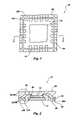
- FIG. 1is a plan view of the bottom of an IC package according to one embodiment of the present invention.
- FIG. 2is a cross-sectional view of the IC package of FIG. 1 ;
- FIGS. 3A and 3Bare enlarged views of the section specified in FIG. 2 at various stages of manufacturing
- FIGS. 4A and 4Bare partial plan views of an IC package according to alternative embodiments.
- FIG. 5is a plan view of a lead frame strip according to one embodiment of the present invention.
- FIG. 6is schematic of a computer system incorporating the IC package of the present invention.
- FIGS. 1 and 2depict one embodiment of an IC package of the present invention in the form of a quad flat no-lead (QFN) grid array package 10 .
- FIG. 1presents a view of a major surface comprising the underside of the QFN package 10
- FIG. 2shows a cross-section of the QFN package 10 taken along section line 2 — 2 as shown in FIG. 1 .
- the QFN package 10includes a semiconductor die 12 positioned on and secured by its back side to a die paddle 14 , die paddle 14 originally comprising a portion of a lead frame as will be hereinafter described.
- Conductive elements 16are positioned about the die paddle 14 in a grid array pattern, outwardly of semiconductor die 12 and adjacent the lateral periphery of QFN package 10 .
- the die paddle 14 and conductive elements 16may be formed of any suitable material such as copper, aluminum, alloy 42 or any other suitable conductive material for lead frames as understood by those of ordinary skill in the art.
- the grid array pattern of the conductive elements 16may be described in various geometrical terms such as a grid having a specified number of columns and rows. However, due to the general placement of the conductive elements 16 outwardly of the semiconductor die 12 and generally adjacent the lateral periphery of the QFN package 10 , the grid array structure will be discussed in terms of peripheral rows. Thus, the QFN package 10 shown in FIGS. 1 and 2 includes a first inner peripheral row 18 A and a second outer peripheral row 18 B of conductive elements 16 .
- peripheral rowis used herein for convenience in describing the configuration of the QFN package 10 and should not be understood as requiring all of the conductive elements 16 to be located at or on the lateral peripheral edge of the QFN package 10 , nor should such phraseology be taken to mean that a given lateral peripheral row of conductive elements 16 must circumscribe the entire die paddle 14 and semiconductor die 12 . While it is desirable to have the conductive elements 16 positioned about each side of the QFN package 10 so as to maximize the number of conductive elements 16 in the package, some designs may not require such an arrangement. Alternatively, some configurations may include peripheral rows that only partially circumscribe the die paddle 14 and semiconductor die 12 , such as arrangements where peripheral rows lie on opposing sides of the QFN package 10 .
- the conductive elements 16are each conductively coupled to a bond pad 22 on the active surface of semiconductor die 12 such as by wire bonds 24 .
- the semiconductor die 12 and wire bonds 24are encapsulated with an electrically insulative (dielectric) material 26 which also partially encapsulates the conductive elements 16 and extends between die paddle 14 and the inner peripheral row 18 A of conductive elements 16 , between the inner peripheral row 18 A of conductive elements 16 and the outer peripheral row 18 B of conductive elements 16 and between laterally adjacent conductive elements 16 of each of the inner and outer peripheral rows 18 A and 18 B, respectfully.
- the encapsulant material 26may comprise a silicon particle-filled polymer encapsulant applied under heat and pressure by transfer molding, as well known in the art.
- the conductive elements 16each have an exposed surface 28 on the bottom major surface of the QFN package 10 for subsequent electrical coupling with another electrical component such as a carrier substrate (not shown).
- a carrier substratesuch as a carrier substrate (not shown).
- Such connectionmay be made, for example, through the use of conductive bumps 28 b , shown in broken lines for clarity.
- bumpsmay include, for example, solder bumps which are stenciled onto conductive elements 16 and then reflowed to form balls, conductive or conductor-filled epoxy columns or pillars, or self-supporting spheres (either conductive or insulative) covered with a conductive material.
- an anisotropic, so-called “Z-axis” conductive materialcomprising laterally-spaced conductive elements in a dielectric film and oriented transversely to the plane thereof may also be employed to connect conductive elements 16 to a carrier substrate.
- the inner peripheral rows 18 A and outer peripheral rows 18 B of conductive elements 16 adjacent each edge of QFN package 10are shown to be separated from one another by an elongated, trough-like concavity or recess 30 .
- the concavity or recess 30is formed as an elongated saw cut or scribe line extending from a first lateral edge of the QFN package 10 to an opposing lateral edge.
- the concavitymay be formed according to other techniques known in the art such as, for example, a masking and etching process. In the embodiment shown in FIGS.
- FIG. 3Adepicts a partial section of the QFN package 10 showing the QFN package 10 at a stage in fabrication prior to formation of the individual conductive elements 16 .
- the QFN package 10 shown in FIG. 3Aincludes a single lead 16 ′ rather than individual conductive elements 16 . It is further noted that there are multiple wire bonds 24 connected to different bonding regions 32 , 34 of the lead 16 ′.
- a severance region 36shown as an upwardly facing notch, is preformed in the lead 16 ′ and subsequently filled with encapsulant 26 subsequent to attachment of semiconductor die 12 to die paddle 14 and wire bonding of a bond pad 22 (not shown in FIG. 3A ) to bonding regions 32 , 34 .
- the notch of severance region 36may be formed by various processes such as saw cutting, scribing, scoring or etching of the lead 16 ′ prior to encapsulation of the lead 16 ′ and wire bond 24 and preferably prior to attachment of semiconductor die 12 to die paddle 14 .
- the lead 16 ′may be severed, such as through the aforementioned saw cutting or etching, to form individual, electrically isolated conductive elements 16 as shown in FIG. 3B .
- Each conductive element 16is connected to a wire bond 24 and thus to a bonding pad 22 of the semiconductor die 12 (not shown in FIG. 3B ).
- the severance region 36serves various purposes. First, the severance region 36 identifies an area of separation on the lead 16 ′. This helps to identify the individual bonding regions 32 , 34 during wire bonding of the lead 16 ′ to the bond pads 22 of the semiconductor die 12 .
- the severance region 36allows for the formation of a more shallow concavity or recess 30 during the separation of the lead 16 ′ into individual conductive elements 16 , such as to minimize the potential for damage to QFN package 10 .
- the transfer-molded encapsulant 26flows under pressure into the notch and substantially laterally about at least three sides of the ultimate location of each conductive element 16 to form a structural member 38 between and about the locations of individual conductive elements 16 to more effectively tie the conductive elements 16 to encapsulant 26 , precisely fixing their locations and enabling the package to withstand the stresses placed on leads 16 ′ without damage thereto or movement thereof.
- the severance region 36is desirably in the form of a notch or recess as shown, it is contemplated that the severance region 36 of the lead 16 ′ may simply be a designated area of separation without a notch or other physical feature. It is noted that, in such a case, the concavity or recess 30 extending upwardly from the bottom major surface of QFN package 10 would penetrate through the entire thickness of the lead 16 ′ and there would be no encapsulant 26 formed between the adjacent inner and outer individual conductive elements 16 to serve as a structural member 38 .
- a structural member 38could be formed after the formation of the concavity or recess 30 by filling the same with dielectric material regardless of whether or not an upwardly facing, preformed notch or recess in each lead 16 ′ is used to facilitate the formation of individual conductive elements 16 .
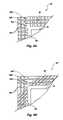
- FIG. 4Ashows a portion of the bottom surface of a QFN package 10 ′ having three different peripheral rows 18 A, 18 B and 18 C of conductive elements 16 .
- the conductive elements 16are formed in a manner similar to that described above except that additional severance regions 36 (or notches) would be located in each lead 16 ′ (see FIGS. 3A , 3 B and 5 ) and that there are additional concavities or recesses 30 to assist in forming the third peripheral row 18 C.
- FIG. 4Bshows a partial section of the bottom surface of a QFN package 10 ′′ also having three peripheral rows 18 A′, 18 B′ and 18 C′.
- the conductive elements 16 ′′ of the peripheral rows 18 A′, 18 B′ and 18 C′are staggered such that a conductive element 16 ′′ in peripheral row 18 B′ is shifted slightly to one side as compared to an adjacent conductive element 16 ′′ in peripheral row 18 A′.
- a conductive element 16 ′′ in peripheral row 18 C′is shifted slightly to one side as compared to an adjacent conductive element 16 ′′ in peripheral row 18 B′.
- Such an arrangementis possible by forming a lead frame having leads positioned at an angle other than perpendicular with respect to an adjacent edge of the die paddle 14 .
- the individual peripheral rows 18 A′, 18 B′ and 18 C′are formed in a manner similar to that described above, with elongated, trough-like concavities or recesses 30 being formed to ultimately create the individual conductive elements 16 ′′.
- the staggered configurationserves to allow more flexibility in wire bonding configurations and potentially lower bond loop heights due to the lateral staggering of the conductive elements 16 ′′.
- the offset of one peripheral row 18 ′, 18 B′ and 18 C′, respectively, relative to anothermay be controlled and wire bonding configurations may be flexibly designed.
- each lead frame 52includes an outer frame portion 52 o bearing a die paddle 14 supported substantially in the center thereof by tie bars and multiple inwardly extending, cantilevered leads 16 ′.
- a reduced number of leads 16 ′is shown for clarity, but is not intended to be limiting of the invention.
- the leads 16 ′are each formed with a severance region 36 , such as a notch or similar recess, for subsequent formation of individual conductive elements 16 from the leads 16 ′.
- the severance regions 36may be formed by various techniques such as scoring, saw cutting, or etching.
- the severance regions 36define the locations of the peripheral rows 18 A and 18 B which will be subsequently formed in the QFN package 10 .
- the lead frames 52 depicted in FIG. 5are representative of a lead frame 52 which might be used in the formation of a QFN package 10 described in conjunction with FIGS. 1 and 2 .
- Other lead frames of suitable configuration and with similar featureswould be utilized in forming the QFN packages 10 ′, 10 ′′ discussed in conjunction with FIGS. 4A or 4 B, respectively, as is understood by those of ordinary skill in the art.
- the outer frame portions 52 oare severed from the packages to effect electrical isolation of die paddle 14 as well as each set of conductive elements 16 from the outer frame portions 52 o , while mutual electrical isolation between the conductive elements 16 formed from each lead 16 ′ is effected by cutting through the leads 16 ′ from the lead surfaces opposite the notches of severance regions 36 .
- QFN packages 10be severed from outer frame portions 52 o after such concavities or recesses 30 are cut or otherwise formed. If conductive bumps 28 b (see FIG. 2 ) are to be formed or placed on conductive elements 16 , it may also be desirable to form or place conductive bumps 28 b while QFN packages 10 are still unsevered from lead frame strip 50 to facilitate alignment and handling.
- FIG. 6a schematic of an electronic system 60 , such as a personal computer, including an input device 62 (such as a keyboard and mouse) and an output device 64 (such as a display or printer interface) coupled or otherwise in electrical communication with a processor device 66 , is illustrated.
- Processor device 66is also coupled or otherwise in operable electrical communication such as through traces of a motherboard with one or more memory modules 68 incorporating a plurality of QFN packages according to the present invention such as 10 , 10 ′, 10 ′′ or variations thereof.
- the memory module 68may include a memory board 70 having an electrical circuit formed therein, such as a printed circuit board (PCB).
- PCBprinted circuit board
- processor, device 66may be directly embodied in a module with a QFN package which incorporates the teachings hereof and may further include, without limitation, a microprocessor, a first level cache memory, and additional ICs, such as logic circuits, a video processor, an audio processor, or a memory management processor.
Landscapes
- Physics & Mathematics (AREA)
- Engineering & Computer Science (AREA)
- Condensed Matter Physics & Semiconductors (AREA)
- General Physics & Mathematics (AREA)
- Computer Hardware Design (AREA)
- Microelectronics & Electronic Packaging (AREA)
- Power Engineering (AREA)
- Geometry (AREA)
- Manufacturing & Machinery (AREA)
- Lead Frames For Integrated Circuits (AREA)
Abstract
Description
Claims (20)
Priority Applications (1)
| Application Number | Priority Date | Filing Date | Title |
|---|---|---|---|
| US10/729,180US7075816B2 (en) | 2001-08-06 | 2003-12-05 | Quad flat no-lead (QFN) grid array package, method of making and memory module and computer system including same |
Applications Claiming Priority (4)
| Application Number | Priority Date | Filing Date | Title |
|---|---|---|---|
| SG200104675-4 | 2001-08-06 | ||
| SG200104675ASG120858A1 (en) | 2001-08-06 | 2001-08-06 | Quad flat no-lead (qfn) grid array package, methodof making and memory module and computer system including same |
| US09/933,297US6967125B2 (en) | 2001-08-06 | 2001-08-20 | Quad flat no lead (QFN) grid array package, method of making and memory module and computer system including same |
| US10/729,180US7075816B2 (en) | 2001-08-06 | 2003-12-05 | Quad flat no-lead (QFN) grid array package, method of making and memory module and computer system including same |
Related Parent Applications (1)
| Application Number | Title | Priority Date | Filing Date |
|---|---|---|---|
| US09/933,297DivisionUS6967125B2 (en) | 2001-08-06 | 2001-08-20 | Quad flat no lead (QFN) grid array package, method of making and memory module and computer system including same |
Publications (2)
| Publication Number | Publication Date |
|---|---|
| US20040114426A1 US20040114426A1 (en) | 2004-06-17 |
| US7075816B2true US7075816B2 (en) | 2006-07-11 |
Family
ID=27800895
Family Applications (4)
| Application Number | Title | Priority Date | Filing Date |
|---|---|---|---|
| US09/933,297Expired - LifetimeUS6967125B2 (en) | 2001-08-06 | 2001-08-20 | Quad flat no lead (QFN) grid array package, method of making and memory module and computer system including same |
| US10/729,180Expired - LifetimeUS7075816B2 (en) | 2001-08-06 | 2003-12-05 | Quad flat no-lead (QFN) grid array package, method of making and memory module and computer system including same |
| US10/728,413Expired - LifetimeUS7109572B2 (en) | 2001-08-06 | 2003-12-05 | Quad flat no lead (QFN) grid array package |
| US11/215,620Expired - LifetimeUS7279780B2 (en) | 2001-08-06 | 2005-08-30 | Quad flat no-lead (QFN) grid array package, method of making and memory module and computer system including same |
Family Applications Before (1)
| Application Number | Title | Priority Date | Filing Date |
|---|---|---|---|
| US09/933,297Expired - LifetimeUS6967125B2 (en) | 2001-08-06 | 2001-08-20 | Quad flat no lead (QFN) grid array package, method of making and memory module and computer system including same |
Family Applications After (2)
| Application Number | Title | Priority Date | Filing Date |
|---|---|---|---|
| US10/728,413Expired - LifetimeUS7109572B2 (en) | 2001-08-06 | 2003-12-05 | Quad flat no lead (QFN) grid array package |
| US11/215,620Expired - LifetimeUS7279780B2 (en) | 2001-08-06 | 2005-08-30 | Quad flat no-lead (QFN) grid array package, method of making and memory module and computer system including same |
Country Status (2)
| Country | Link |
|---|---|
| US (4) | US6967125B2 (en) |
| SG (1) | SG120858A1 (en) |
Cited By (35)
| Publication number | Priority date | Publication date | Assignee | Title |
|---|---|---|---|---|
| US20070281392A1 (en)* | 2006-06-05 | 2007-12-06 | Carsem (M) Sdn. Bhd. | Multiple row exposed leads for mlp high density packages |
| US20090091009A1 (en)* | 2007-10-03 | 2009-04-09 | Corisis David J | Stackable integrated circuit package |
| US7732899B1 (en) | 2005-12-02 | 2010-06-08 | Amkor Technology, Inc. | Etch singulated semiconductor package |
| US7808084B1 (en) | 2008-05-06 | 2010-10-05 | Amkor Technology, Inc. | Semiconductor package with half-etched locking features |
| US7847392B1 (en) | 2008-09-30 | 2010-12-07 | Amkor Technology, Inc. | Semiconductor device including leadframe with increased I/O |
| US7875963B1 (en) | 2008-11-21 | 2011-01-25 | Amkor Technology, Inc. | Semiconductor device including leadframe having power bars and increased I/O |
| US7928542B2 (en) | 2001-03-27 | 2011-04-19 | Amkor Technology, Inc. | Lead frame for semiconductor package |
| US7960818B1 (en) | 2009-03-04 | 2011-06-14 | Amkor Technology, Inc. | Conformal shield on punch QFN semiconductor package |
| US7968998B1 (en) | 2006-06-21 | 2011-06-28 | Amkor Technology, Inc. | Side leaded, bottom exposed pad and bottom exposed lead fusion quad flat semiconductor package |
| US7977774B2 (en) | 2007-07-10 | 2011-07-12 | Amkor Technology, Inc. | Fusion quad flat semiconductor package |
| US7982298B1 (en) | 2008-12-03 | 2011-07-19 | Amkor Technology, Inc. | Package in package semiconductor device |
| US7989933B1 (en) | 2008-10-06 | 2011-08-02 | Amkor Technology, Inc. | Increased I/O leadframe and semiconductor device including same |
| US8008758B1 (en) | 2008-10-27 | 2011-08-30 | Amkor Technology, Inc. | Semiconductor device with increased I/O leadframe |
| US8026589B1 (en) | 2009-02-23 | 2011-09-27 | Amkor Technology, Inc. | Reduced profile stackable semiconductor package |
| US8058715B1 (en) | 2009-01-09 | 2011-11-15 | Amkor Technology, Inc. | Package in package device for RF transceiver module |
| US8067821B1 (en) | 2008-04-10 | 2011-11-29 | Amkor Technology, Inc. | Flat semiconductor package with half package molding |
| US8072050B1 (en) | 2008-11-18 | 2011-12-06 | Amkor Technology, Inc. | Semiconductor device with increased I/O leadframe including passive device |
| US8089145B1 (en) | 2008-11-17 | 2012-01-03 | Amkor Technology, Inc. | Semiconductor device including increased capacity leadframe |
| US8184453B1 (en) | 2008-07-31 | 2012-05-22 | Amkor Technology, Inc. | Increased capacity semiconductor package |
| US8318287B1 (en) | 1998-06-24 | 2012-11-27 | Amkor Technology, Inc. | Integrated circuit package and method of making the same |
| US8487420B1 (en) | 2008-12-08 | 2013-07-16 | Amkor Technology, Inc. | Package in package semiconductor device with film over wire |
| US8575742B1 (en) | 2009-04-06 | 2013-11-05 | Amkor Technology, Inc. | Semiconductor device with increased I/O leadframe including power bars |
| TWI423356B (en)* | 2010-05-20 | 2014-01-11 | Adl Engineering Inc | Package method for quad flat no-lead package |
| US8648450B1 (en) | 2011-01-27 | 2014-02-11 | Amkor Technology, Inc. | Semiconductor device including leadframe with a combination of leads and lands |
| US8680656B1 (en) | 2009-01-05 | 2014-03-25 | Amkor Technology, Inc. | Leadframe structure for concentrated photovoltaic receiver package |
| US8729710B1 (en) | 2008-01-16 | 2014-05-20 | Amkor Technology, Inc. | Semiconductor package with patterning layer and method of making same |
| US9184148B2 (en) | 2013-10-24 | 2015-11-10 | Amkor Technology, Inc. | Semiconductor package and method therefor |
| US9184118B2 (en) | 2013-05-02 | 2015-11-10 | Amkor Technology Inc. | Micro lead frame structure having reinforcing portions and method |
| US20160234938A1 (en)* | 2013-09-18 | 2016-08-11 | Novalia Ltd | Circuit board assembly |
| US9631481B1 (en) | 2011-01-27 | 2017-04-25 | Amkor Technology, Inc. | Semiconductor device including leadframe with a combination of leads and lands and method |
| US9673122B2 (en) | 2014-05-02 | 2017-06-06 | Amkor Technology, Inc. | Micro lead frame structure having reinforcing portions and method |
| US9704725B1 (en) | 2012-03-06 | 2017-07-11 | Amkor Technology, Inc. | Semiconductor device with leadframe configured to facilitate reduced burr formation |
| US10304759B2 (en) | 2015-08-21 | 2019-05-28 | Nexperia B.V. | Electronic device and method of making same |
| US10577130B1 (en)* | 2016-12-07 | 2020-03-03 | Space Systems/Loral, Llc | Flexible radio frequency converters for digital payloads |
| US10811341B2 (en) | 2009-01-05 | 2020-10-20 | Amkor Technology Singapore Holding Pte Ltd. | Semiconductor device with through-mold via |
Families Citing this family (94)
| Publication number | Priority date | Publication date | Assignee | Title |
|---|---|---|---|---|
| US7332375B1 (en) | 1998-06-24 | 2008-02-19 | Amkor Technology, Inc. | Method of making an integrated circuit package |
| US6576494B1 (en)* | 2000-06-28 | 2003-06-10 | Micron Technology, Inc. | Recessed encapsulated microelectronic devices and methods for formation |
| SG120858A1 (en)* | 2001-08-06 | 2006-04-26 | Micron Technology Inc | Quad flat no-lead (qfn) grid array package, methodof making and memory module and computer system including same |
| JP2003204027A (en)* | 2002-01-09 | 2003-07-18 | Matsushita Electric Ind Co Ltd | Lead frame and method of manufacturing the same, resin-sealed semiconductor device and method of manufacturing the same |
| US6838751B2 (en)* | 2002-03-06 | 2005-01-04 | Freescale Semiconductor Inc. | Multi-row leadframe |
| SG120879A1 (en)* | 2002-08-08 | 2006-04-26 | Micron Technology Inc | Packaged microelectronic components |
| SG114585A1 (en) | 2002-11-22 | 2005-09-28 | Micron Technology Inc | Packaged microelectronic component assemblies |
| US6930377B1 (en)* | 2002-12-04 | 2005-08-16 | National Semiconductor Corporation | Using adhesive materials as insulation coatings for leadless lead frame semiconductor packages |
| JP4073308B2 (en)* | 2002-12-20 | 2008-04-09 | 三洋電機株式会社 | Circuit device manufacturing method |
| US6927483B1 (en)* | 2003-03-07 | 2005-08-09 | Amkor Technology, Inc. | Semiconductor package exhibiting efficient lead placement |
| CN101587869B (en)* | 2003-08-26 | 2011-04-13 | 宇芯(毛里求斯)控股有限公司 | Reversible leadless package and methods of making and using same |
| US7144517B1 (en)* | 2003-11-07 | 2006-12-05 | Amkor Technology, Inc. | Manufacturing method for leadframe and for semiconductor package using the leadframe |
| JP2005191342A (en)* | 2003-12-26 | 2005-07-14 | Renesas Technology Corp | Semiconductor device and manufacturing method thereof |
| TW200522292A (en)* | 2003-12-31 | 2005-07-01 | Advanced Semiconductor Eng | Chip package sturcture |
| JP2005203390A (en)* | 2004-01-13 | 2005-07-28 | Seiko Instruments Inc | Method for manufacturing resin sealing semiconductor device |
| KR101070890B1 (en)* | 2004-04-16 | 2011-10-06 | 삼성테크윈 주식회사 | Method for manufacturing the semiconductor package of multi-row lead type |
| US7095096B1 (en)* | 2004-08-16 | 2006-08-22 | National Semiconductor Corporation | Microarray lead frame |
| US7476976B2 (en)* | 2005-02-23 | 2009-01-13 | Texas Instruments Incorporated | Flip chip package with advanced electrical and thermal properties for high current designs |
| US7846775B1 (en)* | 2005-05-23 | 2010-12-07 | National Semiconductor Corporation | Universal lead frame for micro-array packages |
| WO2007005263A2 (en)* | 2005-06-30 | 2007-01-11 | Fairchild Semiconductor Corporation | Semiconductor die package and method for making the same |
| DE112006003664B4 (en)* | 2006-02-01 | 2011-09-08 | Infineon Technologies Ag | Making a QFN package for an integrated circuit and QFN package made using it, and using a leadframe |
| US7986043B2 (en)* | 2006-03-08 | 2011-07-26 | Stats Chippac Ltd. | Integrated circuit package on package system |
| US7981702B2 (en)* | 2006-03-08 | 2011-07-19 | Stats Chippac Ltd. | Integrated circuit package in package system |
| US8513542B2 (en)* | 2006-03-08 | 2013-08-20 | Stats Chippac Ltd. | Integrated circuit leaded stacked package system |
| US7863737B2 (en)* | 2006-04-01 | 2011-01-04 | Stats Chippac Ltd. | Integrated circuit package system with wire bond pattern |
| US8030138B1 (en) | 2006-07-10 | 2011-10-04 | National Semiconductor Corporation | Methods and systems of packaging integrated circuits |
| US9281218B2 (en)* | 2006-08-30 | 2016-03-08 | United Test And Assembly Center Ltd. | Method of producing a semiconductor package |
| US8101464B2 (en) | 2006-08-30 | 2012-01-24 | Micron Technology, Inc. | Microelectronic devices and methods for manufacturing microelectronic devices |
| US7501693B2 (en)* | 2006-11-17 | 2009-03-10 | Micrel, Inc. | LDO regulator with ground connection through package bottom |
| US7834435B2 (en)* | 2006-12-27 | 2010-11-16 | Mediatek Inc. | Leadframe with extended pad segments between leads and die pad, and leadframe package using the same |
| US8124461B2 (en)* | 2006-12-27 | 2012-02-28 | Mediatek Inc. | Method for manufacturing leadframe, packaging method for using the leadframe and semiconductor package product |
| CN101211794A (en)* | 2006-12-27 | 2008-07-02 | 联发科技股份有限公司 | Method for packaging semiconductor element, method for manufacturing lead frame and semiconductor packaging product |
| US20080157299A1 (en)* | 2006-12-28 | 2008-07-03 | Jeffery Gail Holloway | Microelectronic Assembly Using Chip-On-Lead (COL) and Cantilever Leads |
| KR101391924B1 (en)* | 2007-01-05 | 2014-05-07 | 페어차일드코리아반도체 주식회사 | Semiconductor package |
| US7777310B2 (en)* | 2007-02-02 | 2010-08-17 | Stats Chippac Ltd. | Integrated circuit package system with integral inner lead and paddle |
| JP5122172B2 (en) | 2007-03-30 | 2013-01-16 | ローム株式会社 | Semiconductor light emitting device |
| US20080246129A1 (en)* | 2007-04-04 | 2008-10-09 | Matsushita Electric Industrial Co., Ltd. | Method of manufacturing semiconductor device and semiconductor device |
| US7687899B1 (en) | 2007-08-07 | 2010-03-30 | Amkor Technology, Inc. | Dual laminate package structure with embedded elements |
| US8421198B2 (en)* | 2007-09-18 | 2013-04-16 | Stats Chippac Ltd. | Integrated circuit package system with external interconnects at high density |
| US7915716B2 (en)* | 2007-09-27 | 2011-03-29 | Stats Chippac Ltd. | Integrated circuit package system with leadframe array |
| US7777351B1 (en) | 2007-10-01 | 2010-08-17 | Amkor Technology, Inc. | Thin stacked interposer package |
| US8089159B1 (en) | 2007-10-03 | 2012-01-03 | Amkor Technology, Inc. | Semiconductor package with increased I/O density and method of making the same |
| JP5081578B2 (en)* | 2007-10-25 | 2012-11-28 | ローム株式会社 | Resin-sealed semiconductor device |
| US7847386B1 (en) | 2007-11-05 | 2010-12-07 | Amkor Technology, Inc. | Reduced size stacked semiconductor package and method of making the same |
| US8957515B2 (en)* | 2007-11-07 | 2015-02-17 | Stats Chippac Ltd. | Integrated circuit package system with array of external interconnects |
| US7749809B2 (en)* | 2007-12-17 | 2010-07-06 | National Semiconductor Corporation | Methods and systems for packaging integrated circuits |
| US7948066B2 (en)* | 2007-12-26 | 2011-05-24 | Stats Chippac Ltd. | Integrated circuit package system with lead locking structure |
| US7723852B1 (en) | 2008-01-21 | 2010-05-25 | Amkor Technology, Inc. | Stacked semiconductor package and method of making same |
| US8048781B2 (en)* | 2008-01-24 | 2011-11-01 | National Semiconductor Corporation | Methods and systems for packaging integrated circuits |
| TW200937597A (en)* | 2008-02-20 | 2009-09-01 | Chipmos Technologies Inc | Quad flat non-leaded package structure |
| US7732901B2 (en)* | 2008-03-18 | 2010-06-08 | Stats Chippac Ltd. | Integrated circuit package system with isloated leads |
| US7646083B2 (en)* | 2008-03-31 | 2010-01-12 | Broadcom Corporation | I/O connection scheme for QFN leadframe and package structures |
| US7768135B1 (en) | 2008-04-17 | 2010-08-03 | Amkor Technology, Inc. | Semiconductor package with fast power-up cycle and method of making same |
| US9202777B2 (en)* | 2008-05-30 | 2015-12-01 | Stats Chippac Ltd. | Semiconductor package system with cut multiple lead pads |
| US8125064B1 (en) | 2008-07-28 | 2012-02-28 | Amkor Technology, Inc. | Increased I/O semiconductor package and method of making same |
| TWI383478B (en)* | 2008-09-23 | 2013-01-21 | Radiative semiconductor package and its lead frame and design method | |
| US7994629B2 (en) | 2008-12-05 | 2011-08-09 | Stats Chippac Ltd. | Leadless integrated circuit packaging system and method of manufacture thereof |
| MY163911A (en)* | 2009-03-06 | 2017-11-15 | Shenzhen Standarad Patent & Trademark Agent Ltd | Leadless integrated circuit package having high density contacts |
| US8785253B2 (en) | 2009-04-03 | 2014-07-22 | Kaixin, Inc. | Leadframe for IC package and method of manufacture |
| US8786063B2 (en)* | 2009-05-15 | 2014-07-22 | Stats Chippac Ltd. | Integrated circuit packaging system with leads and transposer and method of manufacture thereof |
| US20100314728A1 (en)* | 2009-06-16 | 2010-12-16 | Tung Lok Li | Ic package having an inductor etched into a leadframe thereof |
| CN102576701B (en) | 2009-09-02 | 2016-08-17 | 凯信公司 | IC package and method of manufacturing the same |
| CN102054717A (en)* | 2009-11-10 | 2011-05-11 | 飞思卡尔半导体公司 | Semiconductor chip grid array package and manufacturing method thereof |
| TWI469289B (en)* | 2009-12-31 | 2015-01-11 | 矽品精密工業股份有限公司 | Semiconductor package structure and fabrication method thereof |
| US8922021B2 (en) | 2011-12-30 | 2014-12-30 | Deca Technologies Inc. | Die up fully molded fan-out wafer level packaging |
| US8604600B2 (en)* | 2011-12-30 | 2013-12-10 | Deca Technologies Inc. | Fully molded fan-out |
| US9576919B2 (en) | 2011-12-30 | 2017-02-21 | Deca Technologies Inc. | Semiconductor device and method comprising redistribution layers |
| US9177926B2 (en) | 2011-12-30 | 2015-11-03 | Deca Technologies Inc | Semiconductor device and method comprising thickened redistribution layers |
| US10373870B2 (en) | 2010-02-16 | 2019-08-06 | Deca Technologies Inc. | Semiconductor device and method of packaging |
| KR101796116B1 (en) | 2010-10-20 | 2017-11-10 | 삼성전자 주식회사 | Semiconductor device, memory module and memory system having the same and operating method thereof |
| US8674485B1 (en) | 2010-12-08 | 2014-03-18 | Amkor Technology, Inc. | Semiconductor device including leadframe with downsets |
| US20120241926A1 (en)* | 2011-03-23 | 2012-09-27 | Zigmund Ramirez Camacho | Integrated circuit packaging system with leveling standoff and method of manufacture thereof |
| US9034697B2 (en)* | 2011-07-14 | 2015-05-19 | Freescale Semiconductor, Inc. | Apparatus and methods for quad flat no lead packaging |
| US10672624B2 (en) | 2011-12-30 | 2020-06-02 | Deca Technologies Inc. | Method of making fully molded peripheral package on package device |
| US9831170B2 (en) | 2011-12-30 | 2017-11-28 | Deca Technologies, Inc. | Fully molded miniaturized semiconductor module |
| US10050004B2 (en) | 2015-11-20 | 2018-08-14 | Deca Technologies Inc. | Fully molded peripheral package on package device |
| US9613830B2 (en) | 2011-12-30 | 2017-04-04 | Deca Technologies Inc. | Fully molded peripheral package on package device |
| WO2013102146A1 (en) | 2011-12-30 | 2013-07-04 | Deca Technologies, Inc. | Die up fully molded fan-out wafer level packaging |
| CN103311210B (en) | 2012-03-06 | 2017-03-01 | 飞思卡尔半导体公司 | For assembling the lead frame of semiconductor device |
| US8637974B2 (en) | 2012-06-14 | 2014-01-28 | Stats Chippac Ltd. | Integrated circuit packaging system with tiebar-less design and method of manufacture thereof |
| US9196504B2 (en) | 2012-07-03 | 2015-11-24 | Utac Dongguan Ltd. | Thermal leadless array package with die attach pad locking feature |
| US8710636B1 (en) | 2013-02-04 | 2014-04-29 | Freescale Semiconductor, Inc. | Lead frame array package with flip chip die attach |
| JP6092645B2 (en)* | 2013-02-07 | 2017-03-08 | エスアイアイ・セミコンダクタ株式会社 | Semiconductor device |
| JP6465394B2 (en)* | 2014-02-21 | 2019-02-06 | 大日本印刷株式会社 | Lead frame and manufacturing method thereof, and semiconductor device and manufacturing method thereof |
| TW201539674A (en)* | 2014-04-10 | 2015-10-16 | Chipmos Technologies Inc | Quad flat no-lead package and manufacturing method thereof |
| US9472528B2 (en) | 2014-06-05 | 2016-10-18 | Freescale Semiconductor, Inc. | Integrated electronic package and method of fabrication |
| US9881857B2 (en) | 2014-06-12 | 2018-01-30 | Taiwan Semiconductor Manufacturing Company, Ltd. | Pad design for reliability enhancement in packages |
| US9824990B2 (en) | 2014-06-12 | 2017-11-21 | Taiwan Semiconductor Manufacturing Company, Ltd. | Pad design for reliability enhancement in packages |
| CN107919339B (en)* | 2016-10-11 | 2022-08-09 | 恩智浦美国有限公司 | Semiconductor device with high density lead array and lead frame |
| US10134660B2 (en)* | 2017-03-23 | 2018-11-20 | Nxp Usa, Inc. | Semiconductor device having corrugated leads and method for forming |
| US11139225B2 (en)* | 2019-06-14 | 2021-10-05 | Advanced Semiconductor Engineering, Inc. | Device including a plurality of leads surrounding a die paddle and method for manufacturing the same |
| US11056453B2 (en) | 2019-06-18 | 2021-07-06 | Deca Technologies Usa, Inc. | Stackable fully molded semiconductor structure with vertical interconnects |
| US11728248B2 (en) | 2021-07-01 | 2023-08-15 | Deca Technologies Usa, Inc. | Fully molded semiconductor structure with through silicon via (TSV) vertical interconnects |
| US12394671B2 (en)* | 2022-02-28 | 2025-08-19 | Texas Instruments Incorporated | Efficient removal of street test devices during wafer dicing |
Citations (35)
| Publication number | Priority date | Publication date | Assignee | Title |
|---|---|---|---|---|
| US5286656A (en)* | 1992-11-02 | 1994-02-15 | National Semiconductor Corporation | Individualized prepackage AC performance testing of IC dies on a wafer using DC parametric test patterns |
| US5656550A (en) | 1994-08-24 | 1997-08-12 | Fujitsu Limited | Method of producing a semicondutor device having a lead portion with outer connecting terminal |
| US5714800A (en)* | 1996-03-21 | 1998-02-03 | Motorola, Inc. | Integrated circuit assembly having a stepped interposer and method |
| US6001671A (en) | 1996-04-18 | 1999-12-14 | Tessera, Inc. | Methods for manufacturing a semiconductor package having a sacrificial layer |
| US6081029A (en) | 1998-03-12 | 2000-06-27 | Matsushita Electronics Corporation | Resin encapsulated semiconductor device having a reduced thickness and improved reliability |
| JP2000243787A (en) | 1999-02-18 | 2000-09-08 | Hitachi Cable Ltd | TAB tape and BGA type semiconductor device using the same |
| US6130473A (en) | 1998-04-02 | 2000-10-10 | National Semiconductor Corporation | Lead frame chip scale package |
| US6150709A (en) | 1996-06-21 | 2000-11-21 | Anam Semiconductor Inc. | Grid array type lead frame having lead ends in different planes |
| US6177722B1 (en) | 1998-04-21 | 2001-01-23 | Atmel Corporation | Leadless array package |
| US6184067B1 (en)* | 1996-06-07 | 2001-02-06 | Micron Technology, Inc. | Memory device with multiple input/output connections |
| US6190938B1 (en) | 1998-02-20 | 2001-02-20 | United Microelectronics Corp. | Cross grid array package structure and method of manufacture |
| US6198165B1 (en) | 1998-05-29 | 2001-03-06 | Sharp Kabushiki Kaisha | Semiconductor device |
| US6229200B1 (en) | 1998-06-10 | 2001-05-08 | Asat Limited | Saw-singulated leadless plastic chip carrier |
| US6281047B1 (en) | 2000-11-10 | 2001-08-28 | Siliconware Precision Industries, Co., Ltd. | Method of singulating a batch of integrated circuit package units constructed on a single matrix base |
| US6284563B1 (en)* | 1995-10-31 | 2001-09-04 | Tessera, Inc. | Method of making compliant microelectronic assemblies |
| US6342730B1 (en) | 2000-01-28 | 2002-01-29 | Advanced Semiconductor Engineering, Inc. | Low-pin-count chip package and manufacturing method thereof |
| US6348726B1 (en) | 2001-01-18 | 2002-02-19 | National Semiconductor Corporation | Multi row leadless leadframe package |
| US6350668B1 (en)* | 1999-06-07 | 2002-02-26 | Kishore K. Chakravorty | Low cost chip size package and method of fabricating the same |
| US6372539B1 (en) | 2000-03-20 | 2002-04-16 | National Semiconductor Corporation | Leadless packaging process using a conductive substrate |
| US6399415B1 (en) | 2000-03-20 | 2002-06-04 | National Semiconductor Corporation | Electrical isolation in panels of leadless IC packages |
| US6400004B1 (en) | 2000-08-17 | 2002-06-04 | Advanced Semiconductor Engineering, Inc. | Leadless semiconductor package |
| US6405359B1 (en)* | 1999-10-05 | 2002-06-11 | Taiwan Semiconductor Manufacturing Co., Ltd | Method for backside failure analysis requiring simple bias conditions |
| US6448633B1 (en) | 1998-11-20 | 2002-09-10 | Amkor Technology, Inc. | Semiconductor package and method of making using leadframe having lead locks to secure leads to encapsulant |
| US20020125559A1 (en) | 2001-03-06 | 2002-09-12 | Mclellan Neil | Enhanced leadless chip carrier |
| US6452255B1 (en) | 2000-03-20 | 2002-09-17 | National Semiconductor, Corp. | Low inductance leadless package |
| US6451627B1 (en) | 1999-09-07 | 2002-09-17 | Motorola, Inc. | Semiconductor device and process for manufacturing and packaging a semiconductor device |
| US6498099B1 (en) | 1998-06-10 | 2002-12-24 | Asat Ltd. | Leadless plastic chip carrier with etch back pad singulation |
| US6585905B1 (en) | 1998-06-10 | 2003-07-01 | Asat Ltd. | Leadless plastic chip carrier with partial etch die attach pad |
| US20030164554A1 (en)* | 2001-08-06 | 2003-09-04 | Fee Setho Sing | Quad flat no lead (QFN) grid array package, method of making and memory module and computer system including same |
| US6635957B2 (en) | 1998-06-10 | 2003-10-21 | Asat Ltd. | Leadless plastic chip carrier with etch back pad singulation and die attach pad array |
| US6686652B1 (en) | 2000-03-20 | 2004-02-03 | National Semiconductor | Locking lead tips and die attach pad for a leadless package apparatus and method |
| US6689640B1 (en) | 2000-10-26 | 2004-02-10 | National Semiconductor Corporation | Chip scale pin array |
| US6700188B2 (en) | 2000-02-29 | 2004-03-02 | Advanced Semiconductor Engineering, Inc. | Low-pin-count chip package having concave die pad and/or connections pads |
| US6777788B1 (en) | 2002-09-10 | 2004-08-17 | National Semiconductor Corporation | Method and structure for applying thick solder layer onto die attach pad |
| US6812552B2 (en) | 2002-04-29 | 2004-11-02 | Advanced Interconnect Technologies Limited | Partially patterned lead frames and methods of making and using the same in semiconductor packaging |
Family Cites Families (2)
| Publication number | Priority date | Publication date | Assignee | Title |
|---|---|---|---|---|
| US5994784A (en)* | 1997-12-18 | 1999-11-30 | Micron Technology, Inc. | Die positioning in integrated circuit packaging |
| US6686852B1 (en)* | 2000-09-15 | 2004-02-03 | Motorola, Inc. | Keypad layout for alphabetic character input |
- 2001
- 2001-08-06SGSG200104675Apatent/SG120858A1/enunknown
- 2001-08-20USUS09/933,297patent/US6967125B2/ennot_activeExpired - Lifetime
- 2003
- 2003-12-05USUS10/729,180patent/US7075816B2/ennot_activeExpired - Lifetime
- 2003-12-05USUS10/728,413patent/US7109572B2/ennot_activeExpired - Lifetime
- 2005
- 2005-08-30USUS11/215,620patent/US7279780B2/ennot_activeExpired - Lifetime
Patent Citations (40)
| Publication number | Priority date | Publication date | Assignee | Title |
|---|---|---|---|---|
| US5286656A (en)* | 1992-11-02 | 1994-02-15 | National Semiconductor Corporation | Individualized prepackage AC performance testing of IC dies on a wafer using DC parametric test patterns |
| US5656550A (en) | 1994-08-24 | 1997-08-12 | Fujitsu Limited | Method of producing a semicondutor device having a lead portion with outer connecting terminal |
| US6255740B1 (en) | 1994-08-24 | 2001-07-03 | Fujitsu Limited | Semiconductor device having a lead portion with outer connecting terminals |
| US6284563B1 (en)* | 1995-10-31 | 2001-09-04 | Tessera, Inc. | Method of making compliant microelectronic assemblies |
| US5714800A (en)* | 1996-03-21 | 1998-02-03 | Motorola, Inc. | Integrated circuit assembly having a stepped interposer and method |
| US6001671A (en) | 1996-04-18 | 1999-12-14 | Tessera, Inc. | Methods for manufacturing a semiconductor package having a sacrificial layer |
| US6294830B1 (en) | 1996-04-18 | 2001-09-25 | Tessera, Inc. | Microelectronic assembly with conductive terminals having an exposed surface through a dielectric layer |
| US6587892B2 (en)* | 1996-06-07 | 2003-07-01 | Micron Technology, Inc. | Method of reducing data communication time |
| US6184067B1 (en)* | 1996-06-07 | 2001-02-06 | Micron Technology, Inc. | Memory device with multiple input/output connections |
| US6150709A (en) | 1996-06-21 | 2000-11-21 | Anam Semiconductor Inc. | Grid array type lead frame having lead ends in different planes |
| US6190938B1 (en) | 1998-02-20 | 2001-02-20 | United Microelectronics Corp. | Cross grid array package structure and method of manufacture |
| US6081029A (en) | 1998-03-12 | 2000-06-27 | Matsushita Electronics Corporation | Resin encapsulated semiconductor device having a reduced thickness and improved reliability |
| US6455348B1 (en) | 1998-03-12 | 2002-09-24 | Matsushita Electric Industrial Co., Ltd. | Lead frame, resin-molded semiconductor device, and method for manufacturing the same |
| US6130473A (en) | 1998-04-02 | 2000-10-10 | National Semiconductor Corporation | Lead frame chip scale package |
| US6177722B1 (en) | 1998-04-21 | 2001-01-23 | Atmel Corporation | Leadless array package |
| US6198165B1 (en) | 1998-05-29 | 2001-03-06 | Sharp Kabushiki Kaisha | Semiconductor device |
| US6229200B1 (en) | 1998-06-10 | 2001-05-08 | Asat Limited | Saw-singulated leadless plastic chip carrier |
| US6635957B2 (en) | 1998-06-10 | 2003-10-21 | Asat Ltd. | Leadless plastic chip carrier with etch back pad singulation and die attach pad array |
| US6585905B1 (en) | 1998-06-10 | 2003-07-01 | Asat Ltd. | Leadless plastic chip carrier with partial etch die attach pad |
| US6498099B1 (en) | 1998-06-10 | 2002-12-24 | Asat Ltd. | Leadless plastic chip carrier with etch back pad singulation |
| US6448633B1 (en) | 1998-11-20 | 2002-09-10 | Amkor Technology, Inc. | Semiconductor package and method of making using leadframe having lead locks to secure leads to encapsulant |
| JP2000243787A (en) | 1999-02-18 | 2000-09-08 | Hitachi Cable Ltd | TAB tape and BGA type semiconductor device using the same |
| US6350668B1 (en)* | 1999-06-07 | 2002-02-26 | Kishore K. Chakravorty | Low cost chip size package and method of fabricating the same |
| US6451627B1 (en) | 1999-09-07 | 2002-09-17 | Motorola, Inc. | Semiconductor device and process for manufacturing and packaging a semiconductor device |
| US6405359B1 (en)* | 1999-10-05 | 2002-06-11 | Taiwan Semiconductor Manufacturing Co., Ltd | Method for backside failure analysis requiring simple bias conditions |
| US6342730B1 (en) | 2000-01-28 | 2002-01-29 | Advanced Semiconductor Engineering, Inc. | Low-pin-count chip package and manufacturing method thereof |
| US6700188B2 (en) | 2000-02-29 | 2004-03-02 | Advanced Semiconductor Engineering, Inc. | Low-pin-count chip package having concave die pad and/or connections pads |
| US6372539B1 (en) | 2000-03-20 | 2002-04-16 | National Semiconductor Corporation | Leadless packaging process using a conductive substrate |
| US6452255B1 (en) | 2000-03-20 | 2002-09-17 | National Semiconductor, Corp. | Low inductance leadless package |
| US6399415B1 (en) | 2000-03-20 | 2002-06-04 | National Semiconductor Corporation | Electrical isolation in panels of leadless IC packages |
| US6686652B1 (en) | 2000-03-20 | 2004-02-03 | National Semiconductor | Locking lead tips and die attach pad for a leadless package apparatus and method |
| US6400004B1 (en) | 2000-08-17 | 2002-06-04 | Advanced Semiconductor Engineering, Inc. | Leadless semiconductor package |
| US6689640B1 (en) | 2000-10-26 | 2004-02-10 | National Semiconductor Corporation | Chip scale pin array |
| US6281047B1 (en) | 2000-11-10 | 2001-08-28 | Siliconware Precision Industries, Co., Ltd. | Method of singulating a batch of integrated circuit package units constructed on a single matrix base |
| US6348726B1 (en) | 2001-01-18 | 2002-02-19 | National Semiconductor Corporation | Multi row leadless leadframe package |
| US20020125559A1 (en) | 2001-03-06 | 2002-09-12 | Mclellan Neil | Enhanced leadless chip carrier |
| US6545347B2 (en) | 2001-03-06 | 2003-04-08 | Asat, Limited | Enhanced leadless chip carrier |
| US20030164554A1 (en)* | 2001-08-06 | 2003-09-04 | Fee Setho Sing | Quad flat no lead (QFN) grid array package, method of making and memory module and computer system including same |
| US6812552B2 (en) | 2002-04-29 | 2004-11-02 | Advanced Interconnect Technologies Limited | Partially patterned lead frames and methods of making and using the same in semiconductor packaging |
| US6777788B1 (en) | 2002-09-10 | 2004-08-17 | National Semiconductor Corporation | Method and structure for applying thick solder layer onto die attach pad |
Non-Patent Citations (1)
| Title |
|---|
| Australian Search Report dated Sep. 8, 2004, 4 pages. |
Cited By (54)
| Publication number | Priority date | Publication date | Assignee | Title |
|---|---|---|---|---|
| US8853836B1 (en) | 1998-06-24 | 2014-10-07 | Amkor Technology, Inc. | Integrated circuit package and method of making the same |
| US8318287B1 (en) | 1998-06-24 | 2012-11-27 | Amkor Technology, Inc. | Integrated circuit package and method of making the same |
| US9224676B1 (en) | 1998-06-24 | 2015-12-29 | Amkor Technology, Inc. | Integrated circuit package and method of making the same |
| US8963301B1 (en) | 1998-06-24 | 2015-02-24 | Amkor Technology, Inc. | Integrated circuit package and method of making the same |
| US8102037B2 (en) | 2001-03-27 | 2012-01-24 | Amkor Technology, Inc. | Leadframe for semiconductor package |
| US7928542B2 (en) | 2001-03-27 | 2011-04-19 | Amkor Technology, Inc. | Lead frame for semiconductor package |
| US7732899B1 (en) | 2005-12-02 | 2010-06-08 | Amkor Technology, Inc. | Etch singulated semiconductor package |
| US20070281392A1 (en)* | 2006-06-05 | 2007-12-06 | Carsem (M) Sdn. Bhd. | Multiple row exposed leads for mlp high density packages |
| US7846774B2 (en)* | 2006-06-05 | 2010-12-07 | Carsem (M) Sdn. Bhd. | Multiple row exposed leads for MLP high density packages |
| US8441110B1 (en) | 2006-06-21 | 2013-05-14 | Amkor Technology, Inc. | Side leaded, bottom exposed pad and bottom exposed lead fusion quad flat semiconductor package |
| US7968998B1 (en) | 2006-06-21 | 2011-06-28 | Amkor Technology, Inc. | Side leaded, bottom exposed pad and bottom exposed lead fusion quad flat semiconductor package |
| US7977774B2 (en) | 2007-07-10 | 2011-07-12 | Amkor Technology, Inc. | Fusion quad flat semiconductor package |
| US8304866B1 (en) | 2007-07-10 | 2012-11-06 | Amkor Technology, Inc. | Fusion quad flat semiconductor package |
| US20090091009A1 (en)* | 2007-10-03 | 2009-04-09 | Corisis David J | Stackable integrated circuit package |
| US8729710B1 (en) | 2008-01-16 | 2014-05-20 | Amkor Technology, Inc. | Semiconductor package with patterning layer and method of making same |
| US8067821B1 (en) | 2008-04-10 | 2011-11-29 | Amkor Technology, Inc. | Flat semiconductor package with half package molding |
| US7808084B1 (en) | 2008-05-06 | 2010-10-05 | Amkor Technology, Inc. | Semiconductor package with half-etched locking features |
| US8184453B1 (en) | 2008-07-31 | 2012-05-22 | Amkor Technology, Inc. | Increased capacity semiconductor package |
| US7847392B1 (en) | 2008-09-30 | 2010-12-07 | Amkor Technology, Inc. | Semiconductor device including leadframe with increased I/O |
| US8299602B1 (en) | 2008-09-30 | 2012-10-30 | Amkor Technology, Inc. | Semiconductor device including leadframe with increased I/O |
| US7989933B1 (en) | 2008-10-06 | 2011-08-02 | Amkor Technology, Inc. | Increased I/O leadframe and semiconductor device including same |
| US8432023B1 (en) | 2008-10-06 | 2013-04-30 | Amkor Technology, Inc. | Increased I/O leadframe and semiconductor device including same |
| US8008758B1 (en) | 2008-10-27 | 2011-08-30 | Amkor Technology, Inc. | Semiconductor device with increased I/O leadframe |
| US8823152B1 (en) | 2008-10-27 | 2014-09-02 | Amkor Technology, Inc. | Semiconductor device with increased I/O leadframe |
| US8089145B1 (en) | 2008-11-17 | 2012-01-03 | Amkor Technology, Inc. | Semiconductor device including increased capacity leadframe |
| US8072050B1 (en) | 2008-11-18 | 2011-12-06 | Amkor Technology, Inc. | Semiconductor device with increased I/O leadframe including passive device |
| US8188579B1 (en) | 2008-11-21 | 2012-05-29 | Amkor Technology, Inc. | Semiconductor device including leadframe having power bars and increased I/O |
| US7875963B1 (en) | 2008-11-21 | 2011-01-25 | Amkor Technology, Inc. | Semiconductor device including leadframe having power bars and increased I/O |
| US7982298B1 (en) | 2008-12-03 | 2011-07-19 | Amkor Technology, Inc. | Package in package semiconductor device |
| US8487420B1 (en) | 2008-12-08 | 2013-07-16 | Amkor Technology, Inc. | Package in package semiconductor device with film over wire |
| US11869829B2 (en) | 2009-01-05 | 2024-01-09 | Amkor Technology Singapore Holding Pte. Ltd. | Semiconductor device with through-mold via |
| US8680656B1 (en) | 2009-01-05 | 2014-03-25 | Amkor Technology, Inc. | Leadframe structure for concentrated photovoltaic receiver package |
| US10811341B2 (en) | 2009-01-05 | 2020-10-20 | Amkor Technology Singapore Holding Pte Ltd. | Semiconductor device with through-mold via |
| US8558365B1 (en) | 2009-01-09 | 2013-10-15 | Amkor Technology, Inc. | Package in package device for RF transceiver module |
| US8058715B1 (en) | 2009-01-09 | 2011-11-15 | Amkor Technology, Inc. | Package in package device for RF transceiver module |
| US8026589B1 (en) | 2009-02-23 | 2011-09-27 | Amkor Technology, Inc. | Reduced profile stackable semiconductor package |
| US8729682B1 (en) | 2009-03-04 | 2014-05-20 | Amkor Technology, Inc. | Conformal shield on punch QFN semiconductor package |
| US7960818B1 (en) | 2009-03-04 | 2011-06-14 | Amkor Technology, Inc. | Conformal shield on punch QFN semiconductor package |
| US8575742B1 (en) | 2009-04-06 | 2013-11-05 | Amkor Technology, Inc. | Semiconductor device with increased I/O leadframe including power bars |
| TWI423356B (en)* | 2010-05-20 | 2014-01-11 | Adl Engineering Inc | Package method for quad flat no-lead package |
| US9631481B1 (en) | 2011-01-27 | 2017-04-25 | Amkor Technology, Inc. | Semiconductor device including leadframe with a combination of leads and lands and method |
| US9275939B1 (en) | 2011-01-27 | 2016-03-01 | Amkor Technology, Inc. | Semiconductor device including leadframe with a combination of leads and lands and method |
| US8648450B1 (en) | 2011-01-27 | 2014-02-11 | Amkor Technology, Inc. | Semiconductor device including leadframe with a combination of leads and lands |
| US9508631B1 (en) | 2011-01-27 | 2016-11-29 | Amkor Technology, Inc. | Semiconductor device including leadframe with a combination of leads and lands and method |
| US9978695B1 (en) | 2011-01-27 | 2018-05-22 | Amkor Technology, Inc. | Semiconductor device including leadframe with a combination of leads and lands and method |
| US10090228B1 (en) | 2012-03-06 | 2018-10-02 | Amkor Technology, Inc. | Semiconductor device with leadframe configured to facilitate reduced burr formation |
| US9704725B1 (en) | 2012-03-06 | 2017-07-11 | Amkor Technology, Inc. | Semiconductor device with leadframe configured to facilitate reduced burr formation |
| US9184118B2 (en) | 2013-05-02 | 2015-11-10 | Amkor Technology Inc. | Micro lead frame structure having reinforcing portions and method |
| US20160234938A1 (en)* | 2013-09-18 | 2016-08-11 | Novalia Ltd | Circuit board assembly |
| US9543235B2 (en) | 2013-10-24 | 2017-01-10 | Amkor Technology, Inc. | Semiconductor package and method therefor |
| US9184148B2 (en) | 2013-10-24 | 2015-11-10 | Amkor Technology, Inc. | Semiconductor package and method therefor |
| US9673122B2 (en) | 2014-05-02 | 2017-06-06 | Amkor Technology, Inc. | Micro lead frame structure having reinforcing portions and method |
| US10304759B2 (en) | 2015-08-21 | 2019-05-28 | Nexperia B.V. | Electronic device and method of making same |
| US10577130B1 (en)* | 2016-12-07 | 2020-03-03 | Space Systems/Loral, Llc | Flexible radio frequency converters for digital payloads |
Also Published As
| Publication number | Publication date |
|---|---|
| US7109572B2 (en) | 2006-09-19 |
| SG120858A1 (en) | 2006-04-26 |
| US20050285241A1 (en) | 2005-12-29 |
| US7279780B2 (en) | 2007-10-09 |
| US20040114426A1 (en) | 2004-06-17 |
| US20040080030A1 (en) | 2004-04-29 |
| US6967125B2 (en) | 2005-11-22 |
| US20030164554A1 (en) | 2003-09-04 |
Similar Documents
| Publication | Publication Date | Title |
|---|---|---|
| US7075816B2 (en) | Quad flat no-lead (QFN) grid array package, method of making and memory module and computer system including same | |
| US10734367B2 (en) | Semiconductor package and method of fabricating the same | |
| US7169651B2 (en) | Process and lead frame for making leadless semiconductor packages | |
| US6798063B2 (en) | Low profile ball grid array package | |
| US6703696B2 (en) | Semiconductor package | |
| US6873032B1 (en) | Thermally enhanced chip scale lead on chip semiconductor package and method of making same | |
| US6380048B1 (en) | Die paddle enhancement for exposed pad in semiconductor packaging | |
| US7534653B2 (en) | Chip packaging process | |
| US6445077B1 (en) | Semiconductor chip package | |
| US6762118B2 (en) | Package having array of metal pegs linked by printed circuit lines | |
| US6975039B2 (en) | Method of forming a ball grid array package | |
| US20070108583A1 (en) | Integrated circuit package-on-package stacking system | |
| US20090146315A1 (en) | Integrated circuit package-on-package stacking system and method of manufacture thereof | |
| KR20040097152A (en) | Multi-row leadframe | |
| KR20050074961A (en) | Semiconductor stacked multi-package module having inverted second package | |
| US5856212A (en) | Method of producing semiconductor package having solder balls | |
| US11869831B2 (en) | Semiconductor package with improved board level reliability | |
| US7064009B1 (en) | Thermally enhanced chip scale lead on chip semiconductor package and method of making same | |
| US20020105077A1 (en) | Semiconductor package having changed substrate design using special wire bonding | |
| US20080164620A1 (en) | Multi-chip package and method of fabricating the same | |
| JP3627238B2 (en) | Semiconductor device and manufacturing method thereof | |
| JPH10154768A (en) | Semiconductor device and manufacturing method thereof | |
| JPH04340750A (en) | Manufacture of semiconductor device | |
| KR100247641B1 (en) | Stacked ball grid array package and its manufacturing method | |
| US8399967B2 (en) | Package structure |
Legal Events
| Date | Code | Title | Description |
|---|---|---|---|
| FEPP | Fee payment procedure | Free format text:PAYOR NUMBER ASSIGNED (ORIGINAL EVENT CODE: ASPN); ENTITY STATUS OF PATENT OWNER: LARGE ENTITY | |
| STCF | Information on status: patent grant | Free format text:PATENTED CASE | |
| FPAY | Fee payment | Year of fee payment:4 | |
| FPAY | Fee payment | Year of fee payment:8 | |
| AS | Assignment | Owner name:U.S. BANK NATIONAL ASSOCIATION, AS COLLATERAL AGENT, CALIFORNIA Free format text:SECURITY INTEREST;ASSIGNOR:MICRON TECHNOLOGY, INC.;REEL/FRAME:038669/0001 Effective date:20160426 Owner name:U.S. BANK NATIONAL ASSOCIATION, AS COLLATERAL AGEN Free format text:SECURITY INTEREST;ASSIGNOR:MICRON TECHNOLOGY, INC.;REEL/FRAME:038669/0001 Effective date:20160426 | |
| AS | Assignment | Owner name:MORGAN STANLEY SENIOR FUNDING, INC., AS COLLATERAL AGENT, MARYLAND Free format text:PATENT SECURITY AGREEMENT;ASSIGNOR:MICRON TECHNOLOGY, INC.;REEL/FRAME:038954/0001 Effective date:20160426 Owner name:MORGAN STANLEY SENIOR FUNDING, INC., AS COLLATERAL Free format text:PATENT SECURITY AGREEMENT;ASSIGNOR:MICRON TECHNOLOGY, INC.;REEL/FRAME:038954/0001 Effective date:20160426 | |
| AS | Assignment | Owner name:U.S. BANK NATIONAL ASSOCIATION, AS COLLATERAL AGENT, CALIFORNIA Free format text:CORRECTIVE ASSIGNMENT TO CORRECT THE REPLACE ERRONEOUSLY FILED PATENT #7358718 WITH THE CORRECT PATENT #7358178 PREVIOUSLY RECORDED ON REEL 038669 FRAME 0001. ASSIGNOR(S) HEREBY CONFIRMS THE SECURITY INTEREST;ASSIGNOR:MICRON TECHNOLOGY, INC.;REEL/FRAME:043079/0001 Effective date:20160426 Owner name:U.S. BANK NATIONAL ASSOCIATION, AS COLLATERAL AGEN Free format text:CORRECTIVE ASSIGNMENT TO CORRECT THE REPLACE ERRONEOUSLY FILED PATENT #7358718 WITH THE CORRECT PATENT #7358178 PREVIOUSLY RECORDED ON REEL 038669 FRAME 0001. ASSIGNOR(S) HEREBY CONFIRMS THE SECURITY INTEREST;ASSIGNOR:MICRON TECHNOLOGY, INC.;REEL/FRAME:043079/0001 Effective date:20160426 | |
| MAFP | Maintenance fee payment | Free format text:PAYMENT OF MAINTENANCE FEE, 12TH YEAR, LARGE ENTITY (ORIGINAL EVENT CODE: M1553) Year of fee payment:12 | |
| AS | Assignment | Owner name:JPMORGAN CHASE BANK, N.A., AS COLLATERAL AGENT, ILLINOIS Free format text:SECURITY INTEREST;ASSIGNORS:MICRON TECHNOLOGY, INC.;MICRON SEMICONDUCTOR PRODUCTS, INC.;REEL/FRAME:047540/0001 Effective date:20180703 Owner name:JPMORGAN CHASE BANK, N.A., AS COLLATERAL AGENT, IL Free format text:SECURITY INTEREST;ASSIGNORS:MICRON TECHNOLOGY, INC.;MICRON SEMICONDUCTOR PRODUCTS, INC.;REEL/FRAME:047540/0001 Effective date:20180703 | |
| AS | Assignment | Owner name:MICRON TECHNOLOGY, INC., IDAHO Free format text:RELEASE BY SECURED PARTY;ASSIGNOR:U.S. BANK NATIONAL ASSOCIATION, AS COLLATERAL AGENT;REEL/FRAME:047243/0001 Effective date:20180629 | |
| AS | Assignment | Owner name:MICRON TECHNOLOGY, INC., IDAHO Free format text:RELEASE BY SECURED PARTY;ASSIGNOR:MORGAN STANLEY SENIOR FUNDING, INC., AS COLLATERAL AGENT;REEL/FRAME:050937/0001 Effective date:20190731 | |
| AS | Assignment | Owner name:MICRON TECHNOLOGY, INC., IDAHO Free format text:RELEASE BY SECURED PARTY;ASSIGNOR:JPMORGAN CHASE BANK, N.A., AS COLLATERAL AGENT;REEL/FRAME:051028/0001 Effective date:20190731 Owner name:MICRON SEMICONDUCTOR PRODUCTS, INC., IDAHO Free format text:RELEASE BY SECURED PARTY;ASSIGNOR:JPMORGAN CHASE BANK, N.A., AS COLLATERAL AGENT;REEL/FRAME:051028/0001 Effective date:20190731 |