US7075789B2 - Mechanical housing - Google Patents
Mechanical housingDownload PDFInfo
- Publication number
- US7075789B2 US7075789B2US10/673,739US67373903AUS7075789B2US 7075789 B2US7075789 B2US 7075789B2US 67373903 AUS67373903 AUS 67373903AUS 7075789 B2US7075789 B2US 7075789B2
- Authority
- US
- United States
- Prior art keywords
- case
- heat sink
- aperture
- cage
- cover
- Prior art date
- Legal status (The legal status is an assumption and is not a legal conclusion. Google has not performed a legal analysis and makes no representation as to the accuracy of the status listed.)
- Expired - Lifetime, expires
Links
Images


Classifications
- H—ELECTRICITY
- H05—ELECTRIC TECHNIQUES NOT OTHERWISE PROVIDED FOR
- H05K—PRINTED CIRCUITS; CASINGS OR CONSTRUCTIONAL DETAILS OF ELECTRIC APPARATUS; MANUFACTURE OF ASSEMBLAGES OF ELECTRICAL COMPONENTS
- H05K7/00—Constructional details common to different types of electric apparatus
- H05K7/20—Modifications to facilitate cooling, ventilating, or heating
- H05K7/2039—Modifications to facilitate cooling, ventilating, or heating characterised by the heat transfer by conduction from the heat generating element to a dissipating body
- H05K7/20409—Outer radiating structures on heat dissipating housings, e.g. fins integrated with the housing
- H—ELECTRICITY
- H04—ELECTRIC COMMUNICATION TECHNIQUE
- H04Q—SELECTING
- H04Q1/00—Details of selecting apparatus or arrangements
- H04Q1/02—Constructional details
- H04Q1/035—Cooling of active equipments, e.g. air ducts
- H—ELECTRICITY
- H04—ELECTRIC COMMUNICATION TECHNIQUE
- H04Q—SELECTING
- H04Q1/00—Details of selecting apparatus or arrangements
- H04Q1/02—Constructional details
- H04Q1/09—Frames or mounting racks not otherwise provided for
- H—ELECTRICITY
- H05—ELECTRIC TECHNIQUES NOT OTHERWISE PROVIDED FOR
- H05K—PRINTED CIRCUITS; CASINGS OR CONSTRUCTIONAL DETAILS OF ELECTRIC APPARATUS; MANUFACTURE OF ASSEMBLAGES OF ELECTRICAL COMPONENTS
- H05K7/00—Constructional details common to different types of electric apparatus
- H05K7/20—Modifications to facilitate cooling, ventilating, or heating
- H05K7/2039—Modifications to facilitate cooling, ventilating, or heating characterised by the heat transfer by conduction from the heat generating element to a dissipating body
- H05K7/20409—Outer radiating structures on heat dissipating housings, e.g. fins integrated with the housing
- H05K7/20418—Outer radiating structures on heat dissipating housings, e.g. fins integrated with the housing the radiating structures being additional and fastened onto the housing
- H—ELECTRICITY
- H05—ELECTRIC TECHNIQUES NOT OTHERWISE PROVIDED FOR
- H05K—PRINTED CIRCUITS; CASINGS OR CONSTRUCTIONAL DETAILS OF ELECTRIC APPARATUS; MANUFACTURE OF ASSEMBLAGES OF ELECTRICAL COMPONENTS
- H05K7/00—Constructional details common to different types of electric apparatus
- H05K7/20—Modifications to facilitate cooling, ventilating, or heating
- H05K7/2039—Modifications to facilitate cooling, ventilating, or heating characterised by the heat transfer by conduction from the heat generating element to a dissipating body
- H05K7/20436—Inner thermal coupling elements in heat dissipating housings, e.g. protrusions or depressions integrally formed in the housing
- H05K7/20445—Inner thermal coupling elements in heat dissipating housings, e.g. protrusions or depressions integrally formed in the housing the coupling element being an additional piece, e.g. thermal standoff
- H—ELECTRICITY
- H04—ELECTRIC COMMUNICATION TECHNIQUE
- H04Q—SELECTING
- H04Q2201/00—Constructional details of selecting arrangements
- H04Q2201/06—Cooling arrangements
- H—ELECTRICITY
- H04—ELECTRIC COMMUNICATION TECHNIQUE
- H04Q—SELECTING
- H04Q2201/00—Constructional details of selecting arrangements
- H04Q2201/10—Housing details
- H—ELECTRICITY
- H04—ELECTRIC COMMUNICATION TECHNIQUE
- H04Q—SELECTING
- H04Q2201/00—Constructional details of selecting arrangements
- H04Q2201/12—Printed circuits
Definitions
- the present inventionrelates generally to the field of environmentally protected housings for containing electronic components and, in particular, to the enhanced cooling of electronic components contained within environmentally protected housings.
- Environmentally protected housingsare used in a wide variety of applications, including containing and protecting electronic components of the type used for transferring signals over long distances.
- the telecommunications industrytransfers signals over optical fibers. If the signal is transferred over a long distance, the signal may be too weak by the time it reaches its destination to be useful. Consequently, electronic circuit cards are used to detect, clean up, and amplify a weak signal for retransmission through another length of fiber-optic cable. These electronic circuit cards are often deployed in environmentally protected housings located above and below ground.
- HDSLHigh-Bit-Rate Digital Subscriber Lines
- One way of accomplishing thisis to amplify the signals using electronic circuit cards deployed in environmentally protected housings.
- electronic circuit cards having higher amplification capabilities, and thus greater heat dissipation rates, than the last generation of circuit cards of this typemay be used.
- the need for more electrical signals of this typemay be accommodated by placing as many of these higher-heat-dissipating circuit cards into a single environmentally protected housing as possible.
- existing housings configured to accommodate the heat loads of the last generation of electronic circuit cardscannot accommodate the increased heat load of larger numbers of higher-heat-dissipation electronic circuit cards.
- Embodiments of the present inventionprovide a housing adapted to contain objects, for example electronic circuit cards; at least one case located within the housing, the case adapted to confine the objects to different locations within the housing, the case also thermally coupled to the objects; and at least one heat sink adapted to absorb heat from the case, the heat sink thermally coupled to the case and the housing.
- objectsfor example electronic circuit cards
- the caseadapted to confine the objects to different locations within the housing, the case also thermally coupled to the objects
- at least one heat sinkadapted to absorb heat from the case, the heat sink thermally coupled to the case and the housing.
- the housinghas a partial-shell.
- the partial-shellhas a multitude of fins on its exterior, an aperture, and a cover adapted to selectively seal the aperture against the weather and a pressure differential.
- the partial-shellhas a base adapted to seal the partial-shell against the weather and a pressure differential.
- the partial-shell and the covercan be any material having a suitable combination of thermal properties, corrosion resistance, and strength, such as a formulation of aluminum, bronze, and nickel.
- the basecan be any material having a suitable combination corrosion resistance and strength, such as nylon, plastic, such as ABS, or structural foam.
- the casedefines an object containment volume within the housing.
- the casehas a frame that surrounds the object containment volume.
- the casehas a first partition that divides the object containment volume two individual regions.
- the casehas several second partitions that divide each region into several sections. Each of the second partitions is thermally coupled to the frame and to the first partition.
- Each of the sectionsis divided into several slots.
- Each slotcontains one of the objects.
- Each objectis either thermally coupled to the frame, a second partition, and the first partition or to two second partitions and the first partition.
- the frame, the first partition, and the second partitionscan be any material having suitable thermal properties, such as aluminum, copper bronze, brass, or the like.
- the caseis adapted to selective reconfiguration between operating and non-operating configurations.
- the non-operating configurationis defined by the second partitions of one of the regions being displaced relative to the second partitions of the other region.
- the operating configurationis defined by the second partitions of one of the regions being aligned with the second partitions of the other region.
- At least one heat sinkis thermally coupled to the case.
- the heat sinkis a solid block and can be of any material suitable for heat sinks, such as aluminum, copper bronze, brass, or the like.
- the first embodimenthas a cage attached to the base.
- the cageis adapted to confine the case, including at least one heat sink thermally coupled thereto, to the base.
- the cagecan be of any suitable material, such as plastic. In this configuration at least one heat sink extends through the cage.
- the heat sink protruding therethroughis thermally coupled to the partial-shell.
- the basehas a lead-out, such as for wires used to input and output electrical signals to and from the objects. The lead-out is sealed against the weather and a pressure differential.
- the housinghas a pair of partial-shells.
- the partial shellsare mated together to form a single-shell that has opposing first and second openings.
- Each of the partial shellshas a number of fins on its exterior.
- the partial-shellscan be of a material equivalent to that of the partial shell of the first embodiment.
- the embodimentincludes a case that can be structurally and functionally equivalent to the case of the first embodiment.
- the embodimentincludes at least one heat sink thermally coupled to the case that can be functionally equivalent to the heat sink of the first embodiment.
- the case and the heat sinkcan be of materials equivalent to the case and heat sink of the first embodiment, respectively.
- the second embodimenthas a cage that contains the case, including at least one heat sink thermally coupled thereto.
- the cagehas continuous opposing first and second openings.
- the cage, including the case having at least one heat sink thermally coupled thereto,is contained between the partial shells, as mated together to form the single-shell.
- the first opening of the cagecoincides with the first opening of the single shell and the second opening of the cage coincides with at least a portion of the second opening of the single shell.
- the second embodimenthas a first cover adapted to selectively simultaneously close the first opening in the single-shell and seal the first opening of the cage against the weather and a pressure differential.
- the second embodimenthas a second cover adapted to simultaneously close at least a portion of the second opening in the single-shell and seal the second opening of the cage against the weather and a pressure differential.
- the first covercan be of the same material as the partial-shells, or a suitable equivalent.
- the second covercan be the same material as the base of the first embodiment, or a suitable equivalent.
- the second coverhas a lead-out, such as for wires used to input and output electrical signals to and from the objects.
- the lead-outis sealed against the weather and a pressure differential.
- the cagecontains the case so that at least one heat sink protrudes through one of its openings and so that the case and the objects contained therein are sealed against the weather and a pressure differential by the first and second covers.
- at least one heat sinkis thermally coupled to one of the partial shells.
- the housinghas a shell.
- the interior of the shellis divided into a pair of compartments by a partition.
- the shellhas a pair of first apertures, one for each compartment.
- the shellhas a second aperture opposite the first apertures.
- the shellhas a pair of first covers, each adapted to selectively seal one of the first apertures against the weather and a pressure differential.
- the shellhas a second cover adapted to seal the second aperture against the weather and a pressure differential.
- the second coverhas a lead-out for wires.
- the shellalso has at least one third aperture located in one of the compartments between and perpendicular to one of the first apertures and the second aperture.
- the shellalso has at least one third cover, each third cover adapted to seal the third aperture against the weather and a pressure differential.
- the third coverhas a number of fins on its exterior. A portion of the third cover can be thermally coupled to a portion of the shell.
- the third embodimentincludes at least one case that can be structurally and functionally equivalent to the case of the first embodiment.
- the casecan be of the same material as the case of the first embodiment, or a suitable equivalent.
- the caseis located in the compartment having the third aperture.
- the third embodimentincludes at least one heat sink that can be functionally equivalent to the heat sink of the first embodiment.
- the heat sinkcan be of the same material as the heat sink of the first embodiment, or a suitable equivalent.
- the heat sinkis thermally coupled to the interior of the third cover and to the case.
- the heat sinkincludes a phase-change material (PCM) that changes from a solid to a liquid and vice versa.
- PCMphase-change material
- the heat sinkincludes a PCM that changes from a liquid to a vapor and vice versa.
- the heat sinkincludes at least one heat pipe.
- a partial shell having a number of fins on its exterior and an apertureis formed.
- a coveris formed and used to selectively seal the aperture against the weather and a pressure differential.
- a base having a lead-outis formed.
- a case adapted to confine the objects to different locations within the housingis formed.
- Forming the caseinvolves forming a frame, a first partition, and a number of second partitions.
- the region within the frameis divided into two regions using the first partition, each region is divided into a number of sections using the second partitions, and a number of slots is formed in each of the sections.
- Thermal couplings between each of the second partitions, the frame, and the first partitionare formed.
- Manufacturing the casealso involves adapting the case to be selectively reconfigured between a non-operating configuration and an operating configuration.
- the non-operating configurationincludes the second partitions of one the regions being displaced relative to the second partitions of the other region.
- the operating configurationincludes the second partitions of one of regions being aligned with the second partitions of the other region.
- An objectsuch as an electronic circuit card, is either thermally coupled to the first partition, frame, and a second partition or to the first partition, frame, and two partitions by ensuring the case is in the non-operating configuration, inserting the object into one of the slots, and selectively reconfiguring the case into the operating configuration.
- a thermally conducting materialof the type specially manufactured for thermal contact situations, can be deployed between the mating surfaces of the thermal couplings.
- At least one heat sinkis formed using a solid block of material.
- the heat sinkis thermally coupled to one of the frame walls.
- a cageis also formed and used to contain the case, including at least one heat sink coupled thereto, so that the heat sink protrudes though the cage.
- Manufacturing the first embodimentalso involves attaching the cage and its contents to the base, inserting the cage into the partial-shell to form a thermal coupling between at least one heat sink and the partial-shell, and using the base to seal the partial-shell against the weather and a pressure differential. Also involved is sealing the lead-out in the base against the weather and a pressure differential.
- two partial-shellsare formed, each having a number of fins on its exterior.
- a case that can be functionally and structurally equivalent to the case of the first embodimentis formed.
- At least one heat sinkis formed using a solid block of material and is thermally coupled to the case.
- a cage having opposing continuous first and second openingsis formed and is used to contain the case, including at least one heat sink coupled thereto, so that at least one heat sink protrudes through the cage.
- the partial-shellsare mated together to form a single-shell about the cage that has first and second openings, the first opening being coincident with the first opening of the cage and at least a portion of the second opening being coincident with the second opening of the cage. Mating the partial-shells about the cage also forms a thermal coupling between at least one heat sink and at least one of the partial-shells.
- a first coveris formed and is used to selectively simultaneously cover the first opening in the single-shell and seal the first opening in the cage against the weather and a pressure differential.
- a second cover having a lead-out, such as for wires,is formed and is used to simultaneously close at least a portion of the second opening in the single-shell and seal the second opening of the cage against the weather and a pressure differential. Sealing the second opening of the cage also involves sealing the lead-out against the weather and a pressure differential. Sealing the first and second openings of the cage also seals the case and the objects contained therein against the weather and a pressure differential.
- a shellis formed.
- the interior of the shell so formedis divided into a pair of compartments by a partition.
- the shell so formedhas a pair of first apertures, one first aperture for each compartment, and a second aperture opposite the first apertures.
- the shell so formedhas at least one third aperture located in one compartment between and perpendicular to one of the first apertures and the second aperture.
- At least one case that can be structurally and functionally equivalent to the case of the first embodimentis formed.
- the caseis positioned in the compartment having the third aperture.
- a pair of first coversis formed and each is used to selectively seal one of the first apertures against the weather and a pressure differential.
- a second cover having a lead out for wiresis formed and used to seal the second aperture. Sealing the second aperture involves sealing the lead-out against the weather and a pressure differential.
- At least one heat sinkstructurally and functionally equivalent to the heat sink of the first embodiment, is formed.
- At least one third coveris formed.
- the third cover so formedhas a number of fins on its exterior and can be of the same material as the partial shell and the cover of the first embodiment, or a suitable equivalent.
- the third coveris used to seal the third aperture against the weather and a pressure differential.
- the heat sinkis thermally coupled to the case and the third cover. A portion of the third cover can be thermally coupled to the shell.
- a heat sinkis formed by configuring it to encapsulate a PCM that changes from a solid to a liquid and vice versa. In manufacturing another embodiment, a heat sink is formed by configuring it to encapsulate a PCM that changes from a liquid to a vapor and vice versa. In manufacturing another embodiment, a heat sink is formed to include at least one heat pipe.
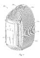
- FIG. 1is a perspective view demonstrating the first embodiment of the present invention as assembled.
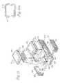
- FIG. 2is an exploded view demonstrating the first embodiment of the present invention.
- FIG. 3is a cross-sectional view demonstrating the operating configuration of the case of the first embodiment of the present invention.
- FIG. 4demonstrates the operating configuration of the case of the first embodiment of the present invention as viewed along 4 — 4 of FIG. 3 .
- FIG. 5is a cross-sectional view demonstrating the non-operating configuration of the case of the first embodiment of the present invention.
- FIG. 6demonstrates the non-operating configuration of the case of the first embodiment of the present invention as viewed along 6 — 6 of FIG. 5 .
- FIG. 7is a perspective view demonstrating the second embodiment of the present invention as assembled.
- FIG. 8is an exploded view demonstrating the second embodiment of the present invention.
- FIG. 9is a back elevation view demonstrating the second embodiment of the present invention.
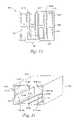
- FIG. 10is a perspective view demonstrating the third embodiment of the present invention as assembled.
- FIG. 11is an exploded view demonstrating the third embodiment of the present invention.
- FIG. 11 ais cover 306 viewed along 11 a — 11 a of FIG. 11 .
- FIGS. 12 , 13 , 14 , 15 , and 16illustrate an alternative embodiment of a case according to the teachings of the present invention.
- Apparatus 100demonstrates a first embodiment of the present invention.
- Apparatus 100has a housing, demonstrated by housing 102 in FIG. 1 .
- Housing 102is adapted to contain objects 104 , shown in FIG. 2 , such as electronic circuit cards.
- Apparatus 100has case 106 contained within housing 102 that is adapted to confine objects 104 to different locations within housing 102 , as demonstrated in FIG. 2 .
- Case 106is thermally coupled to each of objects 104 .
- Apparatus 100has at least one heat sink 108 adapted to absorb heat from case 106 .
- the heat sinkis thermally coupled to case 106 and to housing 102 .
- two heat sinksas demonstrated by heat sinks 108 in FIG. 2 , are used. In other embodiments, additional heat sinks are employed.
- housing 102 of apparatus 100includes partial-shell 110 , shown in FIGS. 1 and 2 .
- Partial-shell 110can have a number of fins, as exemplified by fin 112 in FIG. 1 , distributed on its exterior.
- Partial-shell 110has an aperture, which is covered by cover 114 , as shown in FIGS. 1 and 2 .
- Both partial-shell 110 and cover 114can be of any material having a suitable combination of thermal properties, corrosion resistance, and strength, for example a formulation of aluminum, bronze, and nickel.
- Cover 114selectively seals housing 102 against the weather and a pressure differential. Selective sealing can be accomplished using any suitable method, for example using cap screws or a combination of threaded studs and nuts to compress a suitable gasket, such as a gasket that seals against the weather and a pressure differential, between cover 114 and partial-shell 110 .
- Case 106has walls 118 and walls 120 that constitute a frame, as shown in FIGS. 2 and 3 .
- Case 106has several partitions that divide the region within case 106 into a several sections, as exemplified by partition 122 and section 124 in FIG. 2 .
- Case 106also includes partition 126 , shown in FIG. 4 , that divides the partitioned region within case 106 into two partitioned regions.
- Walls 118 , walls 120 , each partition 122 , and partition 126can be of any material having suitable thermal and strength properties, such as aluminum, copper, etc.
- FIG. 4demonstrates that partition 126 divides each wall 120 into two individual portions, demonstrated by wall portions 120 a and b for one wall and by wall portions 120 c and d for the other wall.
- partition 126divides each partition 122 into two portions, e.g., partitions 122 a, b, and c of FIG. 3 are divided into partition-portions 122 aa and 122 ab, 122 ba and 122 bb, and 122 ca and 122 cb, respectively.
- Each partition 122is thermally coupled to the frame by establishing substantially void-free contact between each partition 122 and each of the walls 118 , as demonstrated in FIG. 2 and by partitions 122 a, b, and c of FIG. 3 .
- Each partition 122is similarly thermally coupled to partition 126 , as demonstrated by partition-portions 122 aa, 122 ab, 122 ba, 122 bb, 122 ca, and 122 cb in FIG. 4 .
- Substantially void-free contactcan be accomplished using any suitable method, such as by polishing or disposing a thermally conducting material between the mating surfaces of walls 118 and each partition 122 and maintaining forced contact between the mating surfaces using any suitable method, such as by clamping, using a resilient material, by wedging, or the like.
- the thermally conducting materialcan be of the type specially manufactured for thermal contact situations such as this.
- Each section 124is divided into several slots, as exemplified by slots 128 a and b in FIG. 3 .
- a slotcan include one groove in one of walls 120 and an opposite groove in the neighboring partition, as exemplified by partition 122 a.
- a slotcan also include opposing slots in neighboring partitions, as exemplified by partitions 122 b and c.
- Each slotcan contain an object 104 , such as an electronic circuit card. As demonstrated by object 104 a in FIGS.
- an objectcan be thermally coupled to a wall 120 , a neighboring partition, as exemplified by 122 a, and partition 126 .
- an objectcan also be thermally coupled to two neighboring partitions, as exemplified by partitions 122 b and c, and partition 126 .
- the configuration demonstrated in FIGS. 3 and 4corresponds to an operating configuration.
- the configuration of case 106can be selectively reconfigured between the operating configuration and a non-operating configuration, demonstrated in FIGS. 5 and 6 .
- the non-operating configurationinvolves a portion, such as wall portion 120 a in FIG. 6 , of at least one of the walls 120 and alternating partition portions, demonstrated by partition portion 122 ba, being displaced relative to the objects, as exemplified by objects 104 a and b.
- FIG. 6demonstrates that wall portion 120 a is displaced relative to wall portion 120 b and partition-portion 122 ba is displaced relative to partition-portion 122 bb.
- Selectively reconfiguring case 106 from the operating to the non-operating configurationfacilitates the insertion and removal of objects 104 .
- Selectively reconfiguring case 106 from the non-operating to the operating configurationsecures each object 104 in place to form one of the thermal couplings described above.
- a thermally conducting materialof the type specially manufactured for thermal contact situations, can be deployed between the mating surfaces.
- Selectively reconfiguring case 106 from the operating to the non-operating configurationcan also involve the other side of partition 126 , e.g., wall portion 120 c and partition-portion 122 bb being displaced relative to wall portion 120 d and partition-portion 122 ba, respectively.
- At least one heat sink 108is thermally coupled to case 106 , but two heat sinks 108 can be thermally coupled to opposing frame-walls, e.g., to walls 120 , as demonstrated in FIG. 2 . Alternatively, at least one heat sink can be thermally coupled to each of the walls 118 and each of the walls 120 .
- Heat sink 108is a solid block of material having thermal properties suitable for heat sinks, such as aluminum, copper, brass, bronze, or the like.
- a thermal couplingcan be established between a heat sink 108 and any of the walls of case 106 by brazing or using a thermally conductive epoxy. Polishing the respective contact surfaces or disposing a thermally conducting material between the respective contact surfaces and screwing the respective heat sink to the respective wall can also be used to establish a thermal coupling between a heat sink 108 and any of the walls of case 106 .
- Apparatus 100has cage 130 adapted to contain case 106 therein.
- Cage 130has openings 132 and openings 133 perpendicular to openings 132 , as shown in FIG. 2 .
- Cage 130has a pair of continuous walls 134 .
- at least one heat sink 108as thermally coupled to a respective wall 120 of case 106 , protrudes through the respective opening 132 .
- each of the walls 118 of case 106can also have at least one heat sink 108 thermally coupled thereto
- each of the walls 134 of cage 130can also have openings so that the respective heat sinks 108 protrude through these openings.
- Cage 130can be of any suitable material, such as plastic.
- Apparatus 100has base 136 adapted to attach cage 130 , containing case 106 therein, thereto.
- Base 136is also adapted to attach partial shell 110 thereto.
- Base 136can be any material having suitable corrosion resistance and strength, such as nylon, plastic, such as ABS, or structural foam.
- base 136comprises a cable head assembly constructed as taught and described in co-pending application Ser. No. 09/804,106 entitled CABLE HEAD ASSEMBLY and filed on even date herewith, which application is incorporated herein by reference.
- thermally conducting pad 138can be of any material having suitable thermal properties, such as aluminum, copper, etc.
- Thermal coupling between a thermally conducting pad 138 and a heat sink 108can be enhanced by polishing the respective contact surfaces or by disposing a thermally conducting material between the respective contact surfaces.
- Thermal coupling of thermally conducting pad 138 to the interior of partial-shell 110can be accomplished by molding, brazing, or epoxying, using a suitable thermally conductive epoxy. Polishing the respective contact surfaces or disposing a thermally conducting material between them and screwing thermally conducting pad 138 to the interior of partial-shell 110 can also be used to thermally couple thermally conducting pad 138 to the interior of partial-shell 110 .
- Cage 130can be attached to base 136 using any suitable method, such as cap screws, nuts and bolts, or a threaded-stud-and-nut arrangement.
- Base 136seals housing 102 against the weather and a pressure differential. Sealing can be accomplished using any suitable sealing method, such as compressing a gasket between base 136 and partial shell 110 .
- Any suitable gasketcan be used, such as a gasket of type employed by the automotive industry for engine-head gaskets.
- the gasketcan be silicone or a suitable equivalent. Compression of the gasket between base 136 and partial shell 110 can be accomplished using any suitable method, such as cap screws or a threaded-stud-and-nut arrangement.
- Base 136can include lead-out 140 , such as for wires used to input and output electrical signals to and from objects 104 .
- Lead-out 140can be sealed against the weather and a pressure differential using any suitable material, such as a suitable elastomer.
- Apparatus 100can be fitted with a pressure relief valve to guard against excessive external-to-internal pressure differences.
- Apparatus 200shown in FIGS. 7–9 , demonstrates a second embodiment of the present invention.
- Apparatus 200has housing 202 , exemplified in FIG. 7 for containing objects, such as electronic circuit cards.
- Apparatus 200has a case disposed within housing 202 that is adapted to confine the objects to different locations within the housing.
- the caseis structurally and functionally equivalent to case 106 described above and exemplified in FIGS. 2–6 for apparatus 100 .
- the caseis of the same material as case 106 , or a suitable equivalent.
- Apparatus 200has at least one heat sink thermally coupled to the case and to housing 202 .
- apparatus 200has two heat sinks, as demonstrated by heat sinks 108 in FIG. 2 for apparatus 100 , or more.
- the heat sinkcan functionally equivalent to heat sink 108 .
- the heat sinkcan be of the same material as heat sink 108 , or a suitable equivalent.
- Apparatus 200has partial-shells 210 a and b.
- Partial-shell 210 ahas opposing openings 210 a 1 and a 2 and partial shell 210 b has opposing openings 210 b 1 and b 2 , as shown in FIG. 8 .
- Partial shells 210 a and bhave a number of fins, demonstrated by fins 212 a and b, respectively, on their exteriors.
- Partial-shells 210 acan be of any material having a suitable combination of thermal properties, corrosion resistance, and strength, for example a formulation of aluminum, bronze, and nickel.
- Apparatus 200has cage 230 adapted to contain the case, including at least one heat sink.
- the heat sinkprotrudes through one of the openings 232 , shown in FIG. 8 , of cage 230 , but an additional heat sink can protrude through the other opening 232 .
- Cage 230can include flange 230 a that frames opening 230 b, an opening opposite opening 230 b that is framed by flange 230 c, and a pair of walls, as demonstrated by walls 234 in FIG. 8 .
- Each of the walls 234can have openings therein so that additional heat sinks thermally coupled to the case can protrude therethrough.
- Cage 230can be of plastic or a suitable equivalent.
- Partial-shells 210 a and bare butted together to form a single-shell about cage 230 that has opposing first and second openings comprising openings 210 a 1 and b 1 and 210 a 2 and b 2 , respectively.
- the first and second openingsare coincident with opening 230 b and the opening framed by flange 230 c, respectively.
- the sealing materialcan be of a thermal conductivity sufficient to thermally couple partial-shells 210 a and b. Cap screws, nuts and bolts, a threaded-stud-and-nut arrangement, or a suitable equivalent can be used to compress the sealing material between partial-shells 210 a and b and to hold partial-shells 210 a and b together.
- Thermally conducting pad 238can be of any material having suitable thermal properties, such as aluminum, copper, etc. There can be at least one thermally conducting pad 238 thermally coupled to partial shells 210 a and b, respectively.
- Thermal coupling of thermally conducting pad 238 to partial-shells 210 a and bcan be accomplished by molding, brazing, or epoxying, using a suitable thermally conductive epoxy. Polishing the respective contact surfaces or disposing a thermally conducting material between them and screwing thermally conducting pad 238 to partial-shells 210 a and b can also be used to thermally couple thermally conducting pad 238 to the interior of partial-shells 210 a and b.
- Apparatus 200has cover 214 that simultaneously selectively covers the first opening in the single-shell and seals opening 230 b of cage 230 against the weather and a pressure differential.
- Cover 214can be of any material having a suitable combination of thermal properties, corrosion resistance, and strength, for example a formulation of aluminum, bronze, and nickel.
- Selective sealing of opening 230 b, using cover 214can be accomplished by compressing a suitable gasket, such as a gasket that seals against the weather and a pressure differential, between cover 214 and flange 230 a of cage 230 , but two gaskets, as demonstrated by gaskets 231 a and b in FIG. 8 , can be used.
- Gaskets 231 a and bcan be of any suitable material, such as silicone, rubber, or the like.
- gasket 231 bis embedded in groove 230 c.
- Groove 230 cis formed in flange 230 a of cage 230 , as shown in FIG. 8 .
- apparatus 200has cover 214 that simultaneously selectively covers the first opening in the single-shell and seals opening 230 b of cage 230 against the weather and a pressure differential.
- Cover 214can be of any material having a suitable combination of thermal properties, corrosion resistance, and strength, for example a formulation of aluminum, bronze, and nickel.
- selective sealing of opening 230 b, using cover 214is accomplished by compressing a suitable gasket, such as gasket 231 b that seals against the weather and a pressure differential, between cover 214 and flange 230 a of cage 230 .
- Gasket 231 bcan be of any suitable material, such as silicone, rubber, or the like.
- heat sink 231 ais sandwiched between the case and cover 214 to thermally couple them.
- Heat sink 231 ais any material or combination of materials having thermal properties suitable for heat sinks, such as aluminum, copper, brass, bronze, or the like.
- a thermal couplingis established between heat sink 231 a and cover 214 while compressing gasket 231 b between cover 214 and flange 230 a, i.e., heat sink 231 a is brought into forced contact with cover 214 and the case using cap screws, a threaded-stud-and-nut arrangement, or the like.
- a thermally conducting materialis disposed between heat sink 231 a and cover 214 and between heat sink 231 a and the case.
- heat sink 231 ais brazed, screwed, bolted, epoxied, using a thermally conductive epoxy, or the like to the case and cover 214 is brought into forced contact with heat sink 231 a using cap screws, a threaded-stud-and-nut arrangement, or the like, while compressing gasket 231 b between cover 214 and flange 230 a.
- heat sink 231 ais brazed, screwed, bolted, epoxied, using a thermally conductive epoxy, or the like to cover 214 and is brought into forced contact with the case using cap screws, a threaded-stud-and-nut arrangement, or the like, while compressing gasket 231 b between cover 214 and flange 230 a.
- heat sink 231 aabsorbs heat dissipated by the objects, e.g. objects 104 of FIG. 2 , confined within the case, as follows: the heat dissipated by the objects is transferred to the case via thermal contact between the objects and the case, and the heat transferred to the case is absorbed by heat sink 231 a via thermal contact between the case and heat sink 231 a. The heat absorbed by heat sink 231 a is transferred to cover 214 via thermal contact between heat sink 231 a and cover 214 and is subsequently transferred exteriorly of cover 214 .
- Apparatus 200has cover 236 .
- cover 236comprises a cable head assembly constructed as taught and described in co-pending application Ser. No. 09/804,106 entitled CABLE HEAD ASSEMBLY and filed on even date herewith, which application is incorporated herein by reference.
- Cover 236can be any material having suitable corrosion resistance and strength, such as nylon, plastic, such as ABS, or structural foam. Cover 236 simultaneously covers the second opening in the single-shell and seals the opening framed by flange 230 c of cage 230 against the weather and a pressure differential. Sealing the opening framed by flange 230 c of cage 230 using cover 236 can be accomplished by compressing a suitable gasket, as demonstrated by gasket 237 , between cover 236 and flange 230 c using any suitable method, such as cap screws or a threaded-stud-and-nut arrangement. Gasket 237 can be of the type employed by the automotive industry for engine-head gaskets and can be of silicone or a suitable equivalent.
- FIG. 9is a back view of apparatus 200 demonstrating cover 236 simultaneously covering the second opening in the single-shell and sealing the opening framed by flange 230 c of cage 230 against the weather and a pressure differential.
- Cover 236includes lead-out 240 such as for wires used to input and output electrical signals to and from the objects.
- Lead-out 240can be sealed against the weather and a pressure differential using any suitable material, such as a suitable elastomer.
- cage 230contains the case containing the objects and including at least one heat sink protruding through one of its openings 232 and when opening 230 b and the opening framed by flange 230 c are sealed by covers 214 and 236 , respectively, the objects are sealed against a pressure differential and the weather.
- the sealed casecan be fitted with a pressure-relief valve to guard against excessive external-to-internal pressure differences.
- Apparatus 300shown in FIGS. 10 and 11 , demonstrates a third embodiment of the present invention.
- FIG. 10demonstrates that apparatus 300 has housing 302 that can be used for containing objects, such as electronic circuit cards.
- Housing 302includes shell 304 that is sealed against the weather and a pressure differential by a pair of first covers 306 and a second cover (not shown) opposite first covers 306 .
- Shell 304can have a number of fins, as exemplified by fin 307 in FIG. 10 , distributed on its exterior.
- Shell 304includes protrusion 305 on each of its ends having an aperture therethrough.
- protrusion 305is a lug.
- a tether 305 apasses through the aperture of each protrusion 305 and through an aperture (not shown) in each of covers 306 to form a loop that interconnects each protrusion 305 to one of covers 306 .
- Tether 305 acan be of any material of suitable tensile strength and corrosion resistance, such as an aramid, e.g., Kevlar, or the like.
- tether 305 ahas two ends, and the respective ends of a tether 305 a are connected to a cover 306 and an end of shell 304 using any suitable method, such as screwing, gluing, riveting, or the like.
- shell 304is divided into two compartments, such as compartment 308 , by partition 310 .
- Shell 304has a pair of first apertures, such as aperture 312 , one for each compartment.
- Each aperture 312is selectively sealed against the weather and a pressure differential by one of covers 306 .
- Shell 304 and covers 306can be of any material having a suitable combination of thermal properties, corrosion resistance, and strength, for example a formulation of aluminum, bronze, and nickel, nylon, ABS, or the like.
- Selective sealing of the respective apertures, using covers 306can accomplished using any suitable method, for example cap screws, nuts-and-bolts, or a combination of threaded studs and nuts, to compress a suitable gasket, such as a gasket that seals against the weather and a pressure differential, between the respective cover 306 and shell 304 .
- a suitable gasketsuch as a gasket that seals against the weather and a pressure differential
- FIG. 11 aillustrates one embodiment of a bottom view of cover 306 .
- Embedded gasket 306 acan be any suitable material that seals against the weather and a pressure differential, such as silicone, rubber, or the like.
- Shell 304has a second aperture opposite covers 306 , sealed by the second cover against the weather and a pressure differential.
- the second covercan include a lead-out.
- the second covercan be any material having suitable corrosion resistance and strength, such as nylon, plastic, ABS, or structural foam.
- Sealing of the second aperture using the second covercan be accomplished using any suitable sealing method, such as compressing a gasket between the second cover and shell 304 .
- Any suitable gasketcan be used, such as a gasket of type employed by the automotive industry for engine-head gaskets that can be of silicone or an equivalent material. Compression of the gasket between the second cover and shell 304 can be accomplished using any suitable method, such as cap screws, nuts-and-bolts, or a threaded-stud-and-nut arrangement.
- the shell 304has at least one third aperture 314 located in one of the compartments between and perpendicular to first aperture 312 and the second aperture. There can be a pair opposing apertures 314 in each compartment, as demonstrated for compartment 308 in FIG. 11 , however.
- the shellalso has at least one third cover 316 , shown in FIG. 11 .
- Cover 316is adapted to seal aperture 314 against the weather and a pressure differential.
- Cover 316has a number of fins, as exemplified by fin 307 , on its exterior and a heat sink, as exemplified by heat sink 320 , thermally coupled to its interior.
- heat sink 320is functionally equivalent to heat sink 108 of apparatus 100 .
- heat sink 320can be of the same material as heat sink 108 , or a suitable equivalent.
- Portion 322 of cover 316can be thermally coupled to a portion of the shell, as demonstrated in FIG. 11 . In the configuration where there can be a pair opposing apertures 314 in each compartment, each aperture is sealed against the weather and a pressure differential by a cover 316 , as demonstrated in FIG. 11 .
- the third embodimentincludes at least one case 324 , shown in FIG. 11 .
- case 324is structurally and functionally equivalent to case 106 of the first embodiment.
- case 324is of the same material as case 106 , or a suitable equivalent. As demonstrated in FIG. 11 , a case 324 can be located in each compartment.
- heat sink 320extends through aperture 314 and is thermally coupled to case 324 .
- Case 400can be as demonstrated by case 400 in FIGS. 12–16 .
- Case 400is disposed within a housing and is adapted to confine objects 401 , such as electronic circuit cards, at different locations within the housing.
- Case 400has walls 402 and walls 404 that constitute frame 406 , demonstrated in FIG. 13 .
- Case 400has at least one partition 408 that divides the region within it into at least two regions.
- Case 400has several partitions 410 - 1 to 410 -N and at least one partition 412 that divide each of the two regions into several sections.
- Walls 402 , walls 404 , each of partitions 410 - 1 to 410 -N, and partition 408can be of any material having suitable thermal and strength properties, such as aluminum, copper, etc.
- Walls 402are thermally coupled to walls 404 .
- Partitions 410 - 1 to 410 -N and partition 412are thermally coupled to walls 404 .
- Partition 408is thermally coupled to walls 402 .
- Thermal contactcan be accomplished using any suitable method, such as by polishing or disposing a thermally conducting material between the contact surfaces and maintaining forced contact between the mating surfaces using any suitable method, such as by using a resilient material or by wedging as described below.
- the thermally conducting materialcan be of the type specially manufactured for thermal contact situations such as this.
- Frame 406has at least one slot 414 adapted to accommodate partition 408 .
- Slot 414includes a pair of opposing grooves 414 a and b as shown.
- Frame 406has several slots 416 - 1 to 416 -M, each adapted to accommodate one of partitions 410 - 1 to 410 -N.
- Each of slots 416 - 1 to 416 -Mrespectively includes a pair of opposing grooves 416 - 1 a and 416 - 1 b to 416 -Ma to 416 -Mb as shown.
- Frame 406has at least one slot 418 adapted to accommodate partition 412 .
- Slot 418includes a pair of opposing grooves 418 a and b as shown.
- FIG. 14is an enlarged view of encircled region 14 of FIG. 12 and demonstrates one embodiment case 400 .
- Partition 410 - j of FIG. 14is any one of partitions 410 - 1 to 410 -N.
- Slot 416 - kis any one of slots 416 - 1 to 416 -M.
- Slot 416 - kis adapted to provide a clearance gap 420 - i on either side of partition 410 - j. This demonstrates that each of slots 416 - 1 to 416 -M is adapted to provide clearance gap on either of its sides.
- Partition 412is composite configuration that includes a pair of outer layers 422 . Outer layers 422 sandwich resilient layer 424 between them.
- Layers 422can be of any material having suitable thermal and strength properties, such as aluminum, copper, etc.
- Layer 424can be any material having suitable resilience properties, such as a suitable elastomeric gasket.
- Slot 418is adapted to provide a clearance gap 426 on either side of partition 412 .
- Resilient layer 424exerts a force on each of layers 422 , which in turn bear against and transmit the force to adjacent objects 401 , as facilitated by clearance gaps 426 .
- an object 401bears against an adjacent partition 410 - j, which transmits the force, as facilitated by their respective clearance gaps 420 - i to the next object 401 .
- This chain of eventscontinues until the objects 401 that are adjacent one of walls 402 are forced against one of walls 402 , thus thermally coupling objects 401 to partition 410 - j and 412 , to a pair of partitions 410 - j, or to a partition 410 - j and one of walls 402 and thus securing objects 401 within case 400 .
- a thermally conducting material of the type specially manufactured for thermal contact situationscan be deployed between the contact surfaces.
- FIG. 15is an enlarged view of encircled region 14 of FIG. 12 and demonstrates another embodiment of case 400 .
- partition 510 - jis equivalent to partition 410 - j of FIG. 14 and is any one of partitions 410 - 1 to 410 -N of FIG. 12 .
- slot 516 - kis equivalent to slot 416 - k of FIG. 14 and is any one of slots 416 - 1 to 416 -M of FIG. 13 .
- Slot 516 - kis adapted to provide a clearance gap 520 - i on either side of partition 510 - j.
- slot 520 - iis equivalent to slot 420 - i of FIG. 14 .
- Partition 512includes a pair of outer layers 522 .
- Layers 522can be of any material having suitable thermal and strength properties, such as aluminum, copper, etc.
- Wedge 524is inserted between layers 522 , as demonstrated in FIG. 16 , a top view of partition 524 .
- Wedge 524can be any suitable material, e.g., plastic, aluminum, copper, or the like.
- wedge 512is replaced by several wedges positioned one above the other at discrete vertical locations between layers 522 .
- Slot 518is adapted to provide a clearance gap 526 on either side of partition 512 .
- wedge 524exerts a force on each of layers 522 , which in turn bear against and transmit the force to adjacent objects 501 , as facilitated by clearance gaps 526 .
- objects 501are equivalent to objects 401 in FIG. 14 .
- an object 501bears against an adjacent partition 510 - j, which transmits the force, as facilitated by clearance gaps 520 - i to the next object 501 .
- each heat sinkis configured to encapsulate a phase-change material (PCM) that changes from a solid to a liquid and vice versa.
- PCMphase-change material
- the PCMcan be any suitable liquid-solid PCM, such as paraffin.
- each heat sinkis configured to encapsulate a PCM that changes from a liquid to a vapor and vice versa.
- the PCMcan be any suitable liquid-vapor PCM, such as FLUROINERT, a product of Dow Chemical Corporation.
- each heat sinkis configured to include at least one heat pipe.
- partial-shell 110including an aperture and a multitude fins on its exterior, as demonstrated by fin 112 in FIG. 1 , is formed.
- Cover 114is formed and used to selectively seal the aperture against the weather and a pressure differential.
- Forming case 106adapted to confine the objects to different locations within the housing, is formed.
- Forming case 106involves forming a frame, partition 126 , and a plurality of second partitions, demonstrated by partition 122 in FIG. 2 .
- the region within the frameis divided into two regions using partition 126 , each region is divided into a plurality of sections, demonstrated by section 124 in FIG. 2 , using the plurality of partitions 122 , and a plurality of slots, demonstrated by slots 128 a and b, is formed in each of the sections 124 .
- Thermal couplings between each of the partitions 122 , the frame, and partition 126are formed.
- Manufacturing case 106also involves adapting it to be selectively reconfigured between a non-operating configuration, as demonstrated in FIGS. 5 and 6 , and an operating configuration, as demonstrated in FIGS. 3 and 4 .
- An objectsuch as an object 104 is either thermally coupled to one of walls 120 , partition 126 , and a neighboring partition, as exemplified by 122 a or to two neighboring partitions, as exemplified by partitions 122 b and c, and to partition 126 by first ensuring the case is in the non-operating configuration. Then, the object is inserted into one of the slots, e.g., 128 a or b, and the case is selectively reconfigured into the operating configuration.
- a thermally conducting material of the type specially manufactured for thermal contact situationscan be deployed between the mating surfaces of the thermal couplings.
- At least one heat sink 108is formed using a solid block of material. As demonstrated in FIG. 2 , two heat sinks 108 can be formed and thermally coupled to one of walls 120 , respectively.
- Manufacturing apparatus 100includes manufacturing cage 130 , positioning case 106 , including at least one heat sink 108 thermally coupled to one of walls 120 , within cage 130 so that at least one heat sink 108 protrudes though an opening 132 .
- Cage 130is attached to base 136 .
- Base 136is attached to partial-shell 110 to seal housing 102 against the weather and a pressure differential. Sealing housing 102 using base 102 also includes sealing lead-out 140 of base 136 against the weather and a pressure differential.
- Manufacturing apparatus 100includes thermally coupling at least one heat sink 108 to partial shell 110 , thermal coupling accomplished by forming a thermally conducting pad 138 and thermally coupling it to the interior of partial-shell 110 .
- Thermal coupling between heat sink 108 and partial shell 110is established by bringing heat sink 108 into thermal contact with a corresponding thermally conducting pad 138 , accomplished by positioning cage 130 within partial-shell 110 .
- partial-shells 210 a and beach having a number of fins on their respective exteriors, as demonstrated by fins 212 a and b, respectively, in FIGS. 7 and 8 are formed.
- a case that can be structurally and functionally equivalent to case 106 , described above for apparatus 100is formed.
- At least one heat sinkis formed and thermally coupled to the case.
- two heat sinkscan be coupled to two opposing walls of the case.
- Manufacturing apparatus 200includes forming cage 230 and positioning the case, including at least one sink thermally coupled thereto, within it so that at least one heat sink protrudes an opening 232 .
- Manufacturing apparatus 200includes butting partial-shells 210 a and b together to form a single-shell about cage 230 that has opposing first and second openings, respectively comprising openings 210 a 1 and b 1 and 210 a 2 and b 2 , shown in FIG. 8 .
- the first and second openingsare coincident with opening 230 b and the second opening framed by flange 230 c of cage 230 , respectively.
- Butting partial-shells 210 a and b togethercan include sealing the abutment against the weather and pressure differential using a suitable material that can also thermally couple partial-shells 210 a and b.
- Cover 214is formed and is used to selectively simultaneously cover the first opening in the single-shell and seal the opening 230 b of the cage against the weather and a pressure differential.
- gasket 231 ais a heat sink and is used to thermally couple the case to cover 214 .
- Cover 236 having lead-out 240is formed and is used to simultaneously close at least a portion of the second opening in the single-shell and seal the opening of cage 230 framed by flange 230 c against the weather and a pressure differential. Sealing the opening of cage 230 framed by flange 230 c also involves sealing lead-out 240 against the weather and a pressure differential. Sealing opening 230 b and the opening framed by flange 230 c of the cage also seals the objects contained within the case against the weather and a pressure differential.
- Manufacturing apparatus 200includes thermally coupling at least one heat sink to partial-shells 210 a or b.
- the thermal couplingis accomplished when partial-shells 210 a and b are butted together to form a single-shell about cage 230 , and at least one heat sink protrudes through one opening 232 in cage 230 and abuts a corresponding thermally conducting pad 238 .
- a suitable thermally conducting materialcan be deployed between the heat sink and thermally conducting pad 238 .
- shell 304is formed.
- the interior of shell 304 so formedis divided into a pair of compartments, such as compartment 308 in FIG. 11 , by partition 310 .
- Shell 304 so formedhas a pair of first apertures 312 and a second aperture opposite apertures 312 .
- Shell 310 so formedhas at least one third aperture 314 located in one compartment between and perpendicular to one of apertures 312 and the second aperture.
- Shell 304 so formedcan have a pair opposing apertures 314 in each compartment, as demonstrated for compartment 308 in FIG. 11 , however.
- At least one case 324that can be structurally and functionally equivalent to the case 106 of apparatus 100 is formed. Case 324 is positioned in the compartment having aperture 314 .
- a pair of first covers 306is formed and each is used to selectively seal one of the first apertures 312 against the weather and a pressure differential.
- a second cover having a lead-out for wiresis formed and used to selectively seal the second aperture. Sealing the second aperture involves sealing the lead-out against the weather and a pressure differential.
- At least one third cover 316is formed.
- Cover 316 so formedhas a number of fins, as demonstrated by fin 307 , on its exterior.
- Third cover 316is used to seal aperture 314 against the weather and a pressure differential.
- Portion 322 of cover 316can be thermally coupled to shell 304 .
- At least one heat sink 320is formed and thermally coupled to case 324 and the interior of cover 316 .
- each aperture 314is sealed against the weather and a pressure differential by a cover 316 .
- a heat sink 320is thermally coupled to the interior of each cover 316 and a case 324 .
- Portion 322 of each cover 316can be thermally coupled to shell 304 .
- each heat sinkis manufactured by configuring it to encapsulate a PCM that changes from a solid to a liquid and vice versa. In another embodiment of the present invention, each heat sink is manufactured by configuring it to encapsulate a PCM that changes from a liquid to a vapor and vice versa. In another embodiment of the present invention, each heat sink is manufactured by configuring it to include at least one heat pipe.
- Embodiments of the present inventionhave been described.
- the embodimentsprovide a housing adapted to contain objects, for example electronic circuit cards; at least one case located within the housing, the case adapted to confine the objects to different locations within the housing, the case also thermally coupled to the objects; and at least one heat sink adapted to absorb heat from the case, the heat sink thermally coupled to the case and the housing.
Landscapes
- Engineering & Computer Science (AREA)
- Physics & Mathematics (AREA)
- Thermal Sciences (AREA)
- Microelectronics & Electronic Packaging (AREA)
- Computer Networks & Wireless Communication (AREA)
- Cooling Or The Like Of Electrical Apparatus (AREA)
- Cooling Or The Like Of Semiconductors Or Solid State Devices (AREA)
Abstract
Description
Claims (13)
Priority Applications (3)
| Application Number | Priority Date | Filing Date | Title |
|---|---|---|---|
| US10/673,739US7075789B2 (en) | 2000-11-06 | 2003-09-29 | Mechanical housing |
| US11/456,270US20070127212A1 (en) | 2000-11-06 | 2006-07-10 | Mechanical Housing |
| US11/932,103US7633757B2 (en) | 2000-11-06 | 2007-10-31 | Mechanical housing |
Applications Claiming Priority (3)
| Application Number | Priority Date | Filing Date | Title |
|---|---|---|---|
| US24617400P | 2000-11-06 | 2000-11-06 | |
| US09/804,129US6628521B2 (en) | 2000-11-06 | 2001-03-12 | Mechanical housing |
| US10/673,739US7075789B2 (en) | 2000-11-06 | 2003-09-29 | Mechanical housing |
Related Parent Applications (1)
| Application Number | Title | Priority Date | Filing Date |
|---|---|---|---|
| US09/804,129ContinuationUS6628521B2 (en) | 2000-11-06 | 2001-03-12 | Mechanical housing |
Related Child Applications (1)
| Application Number | Title | Priority Date | Filing Date |
|---|---|---|---|
| US11/456,270ContinuationUS20070127212A1 (en) | 2000-11-06 | 2006-07-10 | Mechanical Housing |
Publications (2)
| Publication Number | Publication Date |
|---|---|
| US20040163552A1 US20040163552A1 (en) | 2004-08-26 |
| US7075789B2true US7075789B2 (en) | 2006-07-11 |
Family
ID=26937769
Family Applications (4)
| Application Number | Title | Priority Date | Filing Date |
|---|---|---|---|
| US09/804,129Expired - LifetimeUS6628521B2 (en) | 2000-11-06 | 2001-03-12 | Mechanical housing |
| US10/673,739Expired - LifetimeUS7075789B2 (en) | 2000-11-06 | 2003-09-29 | Mechanical housing |
| US11/456,270AbandonedUS20070127212A1 (en) | 2000-11-06 | 2006-07-10 | Mechanical Housing |
| US11/932,103Expired - Fee RelatedUS7633757B2 (en) | 2000-11-06 | 2007-10-31 | Mechanical housing |
Family Applications Before (1)
| Application Number | Title | Priority Date | Filing Date |
|---|---|---|---|
| US09/804,129Expired - LifetimeUS6628521B2 (en) | 2000-11-06 | 2001-03-12 | Mechanical housing |
Family Applications After (2)
| Application Number | Title | Priority Date | Filing Date |
|---|---|---|---|
| US11/456,270AbandonedUS20070127212A1 (en) | 2000-11-06 | 2006-07-10 | Mechanical Housing |
| US11/932,103Expired - Fee RelatedUS7633757B2 (en) | 2000-11-06 | 2007-10-31 | Mechanical housing |
Country Status (4)
| Country | Link |
|---|---|
| US (4) | US6628521B2 (en) |
| AU (1) | AU2002235169A1 (en) |
| CA (1) | CA2428279C (en) |
| WO (1) | WO2002037912A2 (en) |
Cited By (10)
| Publication number | Priority date | Publication date | Assignee | Title |
|---|---|---|---|---|
| US20070115635A1 (en)* | 2005-11-18 | 2007-05-24 | Low Andrew G | Passive cooling for fiber to the premise (FTTP) electronics |
| US7450382B1 (en) | 2007-05-15 | 2008-11-11 | Adc Telecommunications, Inc. | Apparatus for enclosing electronic components |
| US20080278915A1 (en)* | 2007-05-10 | 2008-11-13 | Adc Telecommunications, Inc. | Chassis mounted heat sink system |
| US20080291627A1 (en)* | 2007-05-23 | 2008-11-27 | Adc Telecommunications, Inc. | Apparatus for enclosing electronic components used in telecommunication systems |
| US7734040B1 (en) | 2008-03-25 | 2010-06-08 | Adtran, Inc. | Modular housing system for outside plant telecommunications equipment |
| US20100242590A1 (en)* | 2009-03-27 | 2010-09-30 | Daniel Measurement And Control, Inc. | Flow Meter and Temperature Stabilizing Cover Therefor |
| US7855891B1 (en) | 2008-03-25 | 2010-12-21 | Adtran, Inc. | Modular heat sinks for housings for electronic equipment |
| US20110038120A1 (en)* | 2001-04-24 | 2011-02-17 | Apple Inc. | Heat dissipation in computing device |
| US7915544B1 (en) | 2008-06-05 | 2011-03-29 | Adtran, Inc. | Cable seal apparatus and techniques for outside plant telecommunications housings |
| US20130050939A1 (en)* | 2011-08-28 | 2013-02-28 | Purewave Networks, Inc. | Methods and system for effectively removing heat from a wireless base station |
Families Citing this family (43)
| Publication number | Priority date | Publication date | Assignee | Title |
|---|---|---|---|---|
| KR20030073042A (en)* | 2002-03-08 | 2003-09-19 | 현대네트웍스 주식회사 | Device for cooling of outside the board type system in dsl |
| US7031158B2 (en)* | 2002-10-30 | 2006-04-18 | Charles Industries, Ltd. | Heat pipe cooled electronics enclosure |
| US6781830B2 (en)* | 2002-11-05 | 2004-08-24 | Adc Dsl Systems, Inc. | Methods and systems of heat transfer for electronic enclosures |
| US6979772B2 (en)* | 2003-05-14 | 2005-12-27 | Chaun-Choung Technology Corp. | Integrated heat dissipating enclosure for electronic product |
| USD508469S1 (en)* | 2003-12-18 | 2005-08-16 | Honeywell International Inc. | Housing for an automation system controller |
| USD514075S1 (en)* | 2003-12-18 | 2006-01-31 | Honeywell International Inc. | Housing for an electronic circuit module |
| USD518450S1 (en)* | 2003-12-18 | 2006-04-04 | Honeywell International, Inc. | Modular electronic housing |
| US7164581B2 (en)* | 2004-06-21 | 2007-01-16 | Computer Network Technology Corp. | Modular chassis divided along a midplane and cooling system therefor |
| US20060130221A1 (en)* | 2004-12-20 | 2006-06-22 | Bulala Cherie A | Multi-function toilet device |
| USD518003S1 (en)* | 2005-06-22 | 2006-03-28 | Honeywell International Inc. | Housing for an electronic circuit module |
| US20080098634A1 (en)* | 2006-11-01 | 2008-05-01 | Skyline Products, Inc. | Outdoor display sign |
| USD568841S1 (en) | 2006-12-21 | 2008-05-13 | Adc Telecommunications, Inc. | Enclosure for electronic components |
| US7408782B2 (en)* | 2007-01-04 | 2008-08-05 | Tellabs Bedford, Inc. | Multiple printed circuit board heat transfer guide plates |
| US7796376B2 (en)* | 2008-01-17 | 2010-09-14 | Yaskawa America, Inc. | Electrical enclosure cooling structure assembly and method |
| WO2009113818A2 (en)* | 2008-03-12 | 2009-09-17 | Kmw Inc. | Enclosure device of wireless communication apparatus |
| US7646606B2 (en)* | 2008-05-13 | 2010-01-12 | Honeywell International Inc. | IGBT packaging and cooling using PCM and liquid |
| WO2010028350A1 (en)* | 2008-09-08 | 2010-03-11 | Intergraph Technologies Company | Ruggedized computer capable of operating in high-temperature environments |
| EP2299582B1 (en)* | 2009-09-18 | 2015-03-11 | SMA Solar Technology AG | Inverter with a housing and electric and electronic components assembled within same |
| WO2011119926A2 (en)* | 2010-03-25 | 2011-09-29 | Porreca Paul J | Conduction-cooled apparatus and methods of forming said apparatus |
| BRPI1005385A2 (en)* | 2010-06-28 | 2016-04-12 | Zte Corp | enclosed integrated access system and reduction method for power consumption |
| US8427828B2 (en)* | 2010-07-20 | 2013-04-23 | Themis Computer | Printed circuit board module enclosure and apparatus using same |
| US8537540B2 (en)* | 2010-11-02 | 2013-09-17 | Technology Advancement Group, Inc. | Field serviceable CPU module |
| US20120120594A1 (en)* | 2010-11-12 | 2012-05-17 | Tien-Sheng Huang | Heat dissipating casing structure for main board |
| EP2671434B1 (en)* | 2011-02-04 | 2017-05-17 | Sew-Eurodrive GmbH & Co. KG | Electrical device |
| US8830680B2 (en)* | 2011-07-18 | 2014-09-09 | Public Wireless, Inc. | Systems and methods for heat extraction in a power supply |
| US9161478B2 (en)* | 2012-02-24 | 2015-10-13 | Futurewei Technologies, Inc. | Apparatus and method for an active antenna heat sink |
| US9274548B2 (en)* | 2013-03-01 | 2016-03-01 | Seagate Technology Llc | Electronic apparatus comprising backplane and methods of assembling and disassembling |
| EP3120642B1 (en) | 2014-03-17 | 2023-06-07 | Ubiquiti Inc. | Array antennas having a plurality of directional beams |
| US10327357B2 (en)* | 2014-09-18 | 2019-06-18 | Artesyn Embedded Computing, Inc. | Thermal conduction to a cylindrical shaft |
| US9338907B2 (en)* | 2014-09-24 | 2016-05-10 | Hil Tech Llc | Thermally managed enclosure |
| US10720683B2 (en) | 2014-09-30 | 2020-07-21 | Cps Technology Holdings Llc | Battery module thermal management features for internal flow |
| US9825343B2 (en) | 2014-09-30 | 2017-11-21 | Johnson Controls Technology Company | Battery module passive thermal management features and positioning |
| US10658717B2 (en) | 2014-09-30 | 2020-05-19 | Cps Technology Holdings Llc | Battery module active thermal management features and positioning |
| US10164332B2 (en) | 2014-10-14 | 2018-12-25 | Ubiquiti Networks, Inc. | Multi-sector antennas |
| US10284268B2 (en) | 2015-02-23 | 2019-05-07 | Ubiquiti Networks, Inc. | Radio apparatuses for long-range communication of radio-frequency information |
| TWM523267U (en)* | 2015-07-16 | 2016-06-01 | 鋐寶科技股份有限公司 | Electronic apparatus |
| CN206743244U (en) | 2015-10-09 | 2017-12-12 | 优倍快网络公司 | Multiplexer device |
| US10674641B2 (en)* | 2016-04-04 | 2020-06-02 | Hamilton Sundstrand Corporation | Immersion cooling systems and methods |
| USD835040S1 (en) | 2016-09-09 | 2018-12-04 | Corning Research & Development Corporation | 1×4 distribution point unit |
| WO2020207621A2 (en)* | 2019-04-10 | 2020-10-15 | Sew-Eurodrive Gmbh & Co. Kg | Electric appliance having a housing part |
| USD971900S1 (en) | 2019-06-03 | 2022-12-06 | Space Exploration Technologies Corp. | Antenna apparatus |
| USD971192S1 (en) | 2019-06-03 | 2022-11-29 | Space Exploration Technologies Corp. | Antenna apparatus |
| USD976242S1 (en) | 2019-06-03 | 2023-01-24 | Space Exploration Technologies Corp. | Antenna apparatus |
Citations (88)
| Publication number | Priority date | Publication date | Assignee | Title |
|---|---|---|---|---|
| US2737579A (en) | 1951-04-06 | 1956-03-06 | Acf Ind Inc | Amplifier assembly |
| US2796559A (en) | 1952-09-11 | 1957-06-18 | Bendix Aviat Corp | Electrical apparatus |
| US2833966A (en) | 1956-06-13 | 1958-05-06 | George N Goodier | Heat conducting tube mount |
| US2876277A (en) | 1954-12-29 | 1959-03-03 | Ibm | Electrical component mounting apparatus |
| US3087095A (en) | 1959-12-28 | 1963-04-23 | Bell Telephone Labor Inc | Cushion mounting for electrical apparatus |
| US3135321A (en) | 1960-03-07 | 1964-06-02 | Trane Co | Heat exchanger |
| US3366171A (en) | 1966-07-14 | 1968-01-30 | Bbc Brown Boveri & Cie | Heat sink for semi-conductor elements |
| US3467891A (en) | 1967-10-03 | 1969-09-16 | Gen Electric | Combination electrical,mechanical,and thermal connector assembly |
| US3487267A (en) | 1968-01-02 | 1969-12-30 | Jerrold Electronics Corp | Thermally conducting transistor support arms |
| US3697929A (en) | 1971-01-18 | 1972-10-10 | Bunker Ramo | Controlled insertion force receptacle for flat circuit bearing elements |
| US3767974A (en) | 1972-01-03 | 1973-10-23 | Cogar Corp | Insertion and extraction lever for printed circuit cards |
| US3809798A (en) | 1972-09-06 | 1974-05-07 | H Simon | Angle type feedthrough cable clamp |
| US3997819A (en)* | 1974-09-09 | 1976-12-14 | Siemens Aktiengesellschaft | Housing for electrical communications and measuring devices |
| US4172212A (en) | 1978-07-24 | 1979-10-23 | International Telephone And Telegraph Corporation | Submarine housing for submarine cable system repeater components or the like |
| US4184539A (en) | 1978-07-10 | 1980-01-22 | The United States Of America As Represented By The Secretary Of The Navy | Electronic card mount and heat transfer assembly for underwater vehicles |
| US4259843A (en) | 1979-10-09 | 1981-04-07 | Cromemco Inc. | Isolation chamber for electronic devices |
| JPS5693634A (en) | 1979-12-26 | 1981-07-29 | Motoda Electronics Co Ltd | Device for sucking thin sheet |
| US4301494A (en) | 1979-09-28 | 1981-11-17 | Wescom, Inc. | Printed circuit board faceplate assembly |
| JPS58105187A (en) | 1981-12-17 | 1983-06-22 | 佐瀬 英三 | Flour mill model harnessing water wheel |
| US4449576A (en) | 1980-11-25 | 1984-05-22 | Kabel- Und Metallwerke | Heat-producing elements with heat pipes |
| JPS6079834A (en) | 1983-10-07 | 1985-05-07 | Nec Corp | Structure of optical submarine repeater unit |
| US4528615A (en)* | 1983-05-13 | 1985-07-09 | At&T Bell Laboratories | Repeater housing and circuit mounting structure |
| US4547833A (en) | 1983-12-23 | 1985-10-15 | Schlumberger Technology Corporation | High density electronics packaging system for hostile environment |
| US4559790A (en) | 1982-10-18 | 1985-12-24 | General Electric Company | Apparatus for maintaining electronic equipment and the like at low temperatures in hot ambient environments |
| US4564061A (en) | 1981-12-18 | 1986-01-14 | Ant Nachrichtentechnik Gmbh | Cooling system for communications devices with high power losses |
| JPS6226936A (en) | 1985-07-26 | 1987-02-04 | Nec Corp | Heat dissipation buffering structure of submarine repeater |
| JPS6267936A (en) | 1985-09-19 | 1987-03-27 | Fujitsu Ltd | wireless communication device |
| US4656559A (en) | 1984-05-10 | 1987-04-07 | Ultima Electronics Ltd. | Holder and heat sink for electronic components |
| JPS6279404A (en) | 1985-10-03 | 1987-04-11 | Nec Corp | Optical submarine repeater enclosure |
| US4662002A (en) | 1984-01-19 | 1987-04-28 | Standard Telephones And Cables Public Limited Company | Optical repeaters |
| US4679250A (en) | 1984-01-19 | 1987-07-07 | Standard Telephones And Cables Plc | Optical repeaters |
| GB2193552A (en) | 1986-08-08 | 1988-02-10 | Stc Plc | Repeater housing |
| US4777561A (en) | 1985-03-26 | 1988-10-11 | Hughes Aircraft Company | Electronic module with self-activated heat pipe |
| US4805482A (en) | 1987-08-24 | 1989-02-21 | Brunswick Corporation | Cam adjustment assembly |
| US4815913A (en) | 1987-03-20 | 1989-03-28 | Matsushita Electric Industrial Co., Ltd. | Electronic component mounting device |
| US4858068A (en) | 1986-03-21 | 1989-08-15 | Alcatel Cit | Electronic circuit housing |
| US4858070A (en) | 1987-04-24 | 1989-08-15 | Racal Data Communications Inc. | Modular expandable housing arrangement for electronic apparatus |
| JPH024287A (en) | 1988-06-22 | 1990-01-09 | Olympus Optical Co Ltd | Display control system |
| US4909752A (en) | 1989-03-31 | 1990-03-20 | Honeywell, Inc. | Circuit card retainer |
| JPH02166798A (en) | 1988-12-21 | 1990-06-27 | Nec Corp | Heat radiation structure for communication equipment case |
| US4953058A (en) | 1989-09-01 | 1990-08-28 | General Dynamics Corporation, Space Systems Div. | Modular segment adapted to provide a passively cooled housing for heat generating electronic modules |
| US4962445A (en) | 1988-04-21 | 1990-10-09 | Societe Anonyme Dite: Alcatel Cit | Housing for submersible equipment |
| US4987978A (en) | 1989-10-10 | 1991-01-29 | Jungersen Thoger G | Wheelchair safety brakes |
| US5019939A (en) | 1989-10-24 | 1991-05-28 | Ag Communication Systems Corp. | Thermal management plate |
| US5045971A (en) | 1989-04-18 | 1991-09-03 | Mitsubishi Denki Kabushiki Kaisha | Electronic device housing with temperature management functions |
| US5048793A (en) | 1990-06-14 | 1991-09-17 | Miller Pipeline Corporation | Pipe jack |
| US5089935A (en) | 1990-02-28 | 1992-02-18 | Mitsubishi Denki Kabushiki Kaisha | Control device case |
| US5105337A (en) | 1989-12-29 | 1992-04-14 | Alcatel Cit | Housing for underwater electronic circuits |
| US5267122A (en) | 1992-06-15 | 1993-11-30 | Alcatel Network Systems, Inc. | Optical network unit |
| US5309315A (en) | 1991-08-09 | 1994-05-03 | Pulse Embedded Computer Systems, Inc. | Severe environment enclosure with thermal heat sink and EMI protection |
| US5329425A (en) | 1991-02-25 | 1994-07-12 | Alcatel N.V. | Cooling system |
| US5337218A (en) | 1992-06-02 | 1994-08-09 | International Business Machines Corporation | Circuit card interconnecting structure |
| US5398164A (en) | 1993-02-24 | 1995-03-14 | International Business Machines Corporation | Printed circuit card latching and stiffening assembly |
| US5424916A (en) | 1989-07-28 | 1995-06-13 | The Charles Stark Draper Laboratory, Inc. | Combination conductive and convective heatsink |
| JPH07177645A (en) | 1993-12-21 | 1995-07-14 | Nec Eng Ltd | Heat dissipating/shock absorbing structure for submarine repeater |
| JPH0865868A (en) | 1994-08-19 | 1996-03-08 | Nec Eng Ltd | Heat radiation/buffering structure of submarine repeater |
| US5519573A (en) | 1994-12-27 | 1996-05-21 | Intel Corporation | I/O riser card for motherboard in a personal computer/server |
| US5822196A (en) | 1996-06-05 | 1998-10-13 | Compaq Computer Corporation | Securing a card in an electronic device |
| US5825621A (en) | 1997-06-12 | 1998-10-20 | Harris Corporation | Closed loop cooling housing for printed circuit card-mounted, sealed heat exchanger |
| US5842514A (en) | 1997-03-05 | 1998-12-01 | Northern Telecom Limited | Electronic unit |
| US5864365A (en)* | 1996-01-26 | 1999-01-26 | Kaman Sciences Corporation | Environmentally controlled camera housing assembly |
| US5896268A (en) | 1997-08-11 | 1999-04-20 | Abacon Telecommunications Corporation | Enclosure for high-density subscriber line modules |
| US5923531A (en) | 1997-10-14 | 1999-07-13 | International Business Machines Corporation | Enhanced circuit board arrangement for a computer |
| US5995378A (en) | 1997-12-31 | 1999-11-30 | Micron Technology, Inc. | Semiconductor device socket, assembly and methods |
| US6002588A (en) | 1997-12-04 | 1999-12-14 | Lockheed Martin Corporation | Thermally conductive vibration isolators |
| US6038129A (en) | 1998-04-28 | 2000-03-14 | Lucent Technologies Inc. | Cooling electronic apparatus |
| US6045140A (en) | 1997-07-11 | 2000-04-04 | Cummins Engine Company, Inc. | Retention gasket with cooperating cover |
| US6104611A (en) | 1995-10-05 | 2000-08-15 | Nortel Networks Corporation | Packaging system for thermally controlling the temperature of electronic equipment |
| US6118662A (en) | 1999-11-05 | 2000-09-12 | Special Product Company | Enclosure for telecommunications equipment |
| EP1041002A2 (en) | 1999-04-01 | 2000-10-04 | Negesat Di Boer Fabrizio & C. SNC | Protective casing with cooling for equipment in air, space or land vehicles |
| US6151213A (en) | 1999-05-12 | 2000-11-21 | 3Com Corporation | Ventilation and cooling control system for modular platforms |
| JP2001085879A (en) | 1999-09-13 | 2001-03-30 | Hitachi Ltd | Assembly structure of electronic circuit board |
| US6209631B1 (en) | 1999-07-23 | 2001-04-03 | Esco Electronics Corporation | Thermal management apparatus for a sealed enclosure |
| US6289678B1 (en) | 1998-12-03 | 2001-09-18 | Phoenix Group, Inc. | Environmental system for rugged disk drive |
| US6292361B1 (en) | 1999-12-20 | 2001-09-18 | Dell Usa, L.P. | Apparatus and method for mounting and cooling a system component assembly in a computer |
| US6292556B1 (en) | 1997-11-06 | 2001-09-18 | Anacapa Technology, Inc. | Local loop telecommunication repeater housings employing thermal collection, transfer and distribution via solid thermal conduction |
| US6295208B1 (en) | 1999-02-12 | 2001-09-25 | 3Com Corporation | Backplate for securing a circuit card to a computer chassis |
| US6310772B1 (en) | 1999-09-02 | 2001-10-30 | Special Product Company | Enclosure for telecommunications equipment |
| US20020008962A1 (en) | 2000-02-14 | 2002-01-24 | Hutchison Randall D. | Concentrical slot telecommunications equipment enclosure |
| US6381146B1 (en) | 2000-09-28 | 2002-04-30 | Hewlett-Packard Company | Module removal system |
| US6396691B1 (en)* | 2000-04-17 | 2002-05-28 | Circa Telecom, Usa, Inc. | Thermal cover for T1/HDSL repeater case |
| US6406312B1 (en) | 2001-04-25 | 2002-06-18 | Juniper Networks, Inc. | Circuit card captivation and ejection mechanism including a lever to facilitate removal of the mechanism from a housing |
| US6421252B1 (en) | 2000-11-10 | 2002-07-16 | International Business Machines Corporation | System and method for a self aligning multiple card enclosure with hot plug capability |
| US6430044B2 (en) | 2000-02-10 | 2002-08-06 | Special Product Company | Telecommunications enclosure with individual, separated card holders |
| US6493236B1 (en) | 2001-05-29 | 2002-12-10 | Sony Computer Entertainment Inc. | Electronic equipment |
| US6496385B1 (en) | 1999-09-29 | 2002-12-17 | Silicon Graphics, Inc. | Method and assembly for installation or removal of printed circuit card |
| US6507494B1 (en) | 2000-07-27 | 2003-01-14 | Adc Telecommunications, Inc. | Electronic equipment enclosure |
| US6587339B1 (en) | 2002-03-29 | 2003-07-01 | Thornhurst Manufacturing, Inc. | Protective pot or container |
Family Cites Families (13)
| Publication number | Priority date | Publication date | Assignee | Title |
|---|---|---|---|---|
| US336171A (en)* | 1886-02-16 | Vault-light | ||
| US5264719A (en)* | 1986-01-07 | 1993-11-23 | Harris Corporation | High voltage lateral semiconductor device |
| CA2120468A1 (en)* | 1993-04-05 | 1994-10-06 | Kenneth Alan Salisbury | Electronic module containing an internally ribbed, integral heat sink and bonded, flexible printed wiring board with two-sided component population |
| US5381314A (en)* | 1993-06-11 | 1995-01-10 | The Whitaker Corporation | Heat dissipating EMI/RFI protective function box |
| US5343361A (en)* | 1993-06-11 | 1994-08-30 | The Whitaker Corporation | Thermal junction for card edges in a card cage and ground clip therefor |
| US5455739A (en)* | 1994-04-05 | 1995-10-03 | Alcatel Network Systems, Inc. | Assembly for transferring heat from heat generating components to a surrounding housing |
| US5482888A (en)* | 1994-08-12 | 1996-01-09 | United Microelectronics Corporation | Method of manufacturing a low resistance, high breakdown voltage, power MOSFET |
| JP3233808B2 (en)* | 1995-03-17 | 2001-12-04 | 富士通株式会社 | Electronic package cooling system |
| US5828807A (en)* | 1996-04-30 | 1998-10-27 | Next Level Communications | Optical network unit (ONU) mechanical enclosure |
| US6028769A (en)* | 1996-05-20 | 2000-02-22 | Adc Telecommunication, Inc. | Multiple integrated service unit for communication system |
| US6065530A (en)* | 1997-05-30 | 2000-05-23 | Alcatel Usa Sourcing, L.P. | Weatherproof design for remote transceiver |
| US5918137A (en)* | 1998-04-27 | 1999-06-29 | Spectrian, Inc. | MOS transistor with shield coplanar with gate electrode |
| US6396129B1 (en)* | 2001-03-05 | 2002-05-28 | Siliconware Precision Industries Co., Ltd. | Leadframe with dot array of silver-plated regions on die pad for use in exposed-pad semiconductor package |
- 2001
- 2001-03-12USUS09/804,129patent/US6628521B2/ennot_activeExpired - Lifetime
- 2001-11-05AUAU2002235169Apatent/AU2002235169A1/ennot_activeAbandoned
- 2001-11-05CACA2428279Apatent/CA2428279C/ennot_activeExpired - Fee Related
- 2001-11-05WOPCT/US2001/047232patent/WO2002037912A2/ennot_activeApplication Discontinuation
- 2003
- 2003-09-29USUS10/673,739patent/US7075789B2/ennot_activeExpired - Lifetime
- 2006
- 2006-07-10USUS11/456,270patent/US20070127212A1/ennot_activeAbandoned
- 2007
- 2007-10-31USUS11/932,103patent/US7633757B2/ennot_activeExpired - Fee Related
Patent Citations (94)
| Publication number | Priority date | Publication date | Assignee | Title |
|---|---|---|---|---|
| US2737579A (en) | 1951-04-06 | 1956-03-06 | Acf Ind Inc | Amplifier assembly |
| US2796559A (en) | 1952-09-11 | 1957-06-18 | Bendix Aviat Corp | Electrical apparatus |
| US2876277A (en) | 1954-12-29 | 1959-03-03 | Ibm | Electrical component mounting apparatus |
| US2833966A (en) | 1956-06-13 | 1958-05-06 | George N Goodier | Heat conducting tube mount |
| US3087095A (en) | 1959-12-28 | 1963-04-23 | Bell Telephone Labor Inc | Cushion mounting for electrical apparatus |
| US3135321A (en) | 1960-03-07 | 1964-06-02 | Trane Co | Heat exchanger |
| US3366171A (en) | 1966-07-14 | 1968-01-30 | Bbc Brown Boveri & Cie | Heat sink for semi-conductor elements |
| US3467891A (en) | 1967-10-03 | 1969-09-16 | Gen Electric | Combination electrical,mechanical,and thermal connector assembly |
| US3487267A (en) | 1968-01-02 | 1969-12-30 | Jerrold Electronics Corp | Thermally conducting transistor support arms |
| US3697929A (en) | 1971-01-18 | 1972-10-10 | Bunker Ramo | Controlled insertion force receptacle for flat circuit bearing elements |
| US3767974A (en) | 1972-01-03 | 1973-10-23 | Cogar Corp | Insertion and extraction lever for printed circuit cards |
| US3809798A (en) | 1972-09-06 | 1974-05-07 | H Simon | Angle type feedthrough cable clamp |
| US3997819A (en)* | 1974-09-09 | 1976-12-14 | Siemens Aktiengesellschaft | Housing for electrical communications and measuring devices |
| US4184539A (en) | 1978-07-10 | 1980-01-22 | The United States Of America As Represented By The Secretary Of The Navy | Electronic card mount and heat transfer assembly for underwater vehicles |
| US4172212A (en) | 1978-07-24 | 1979-10-23 | International Telephone And Telegraph Corporation | Submarine housing for submarine cable system repeater components or the like |
| US4301494A (en) | 1979-09-28 | 1981-11-17 | Wescom, Inc. | Printed circuit board faceplate assembly |
| US4259843A (en) | 1979-10-09 | 1981-04-07 | Cromemco Inc. | Isolation chamber for electronic devices |
| JPS5693634A (en) | 1979-12-26 | 1981-07-29 | Motoda Electronics Co Ltd | Device for sucking thin sheet |
| US4449576A (en) | 1980-11-25 | 1984-05-22 | Kabel- Und Metallwerke | Heat-producing elements with heat pipes |
| JPS58105187A (en) | 1981-12-17 | 1983-06-22 | 佐瀬 英三 | Flour mill model harnessing water wheel |
| US4564061A (en) | 1981-12-18 | 1986-01-14 | Ant Nachrichtentechnik Gmbh | Cooling system for communications devices with high power losses |
| US4559790A (en) | 1982-10-18 | 1985-12-24 | General Electric Company | Apparatus for maintaining electronic equipment and the like at low temperatures in hot ambient environments |
| US4528615A (en)* | 1983-05-13 | 1985-07-09 | At&T Bell Laboratories | Repeater housing and circuit mounting structure |
| JPS6079834A (en) | 1983-10-07 | 1985-05-07 | Nec Corp | Structure of optical submarine repeater unit |
| US4547833A (en) | 1983-12-23 | 1985-10-15 | Schlumberger Technology Corporation | High density electronics packaging system for hostile environment |
| US4662002A (en) | 1984-01-19 | 1987-04-28 | Standard Telephones And Cables Public Limited Company | Optical repeaters |
| US4679250A (en) | 1984-01-19 | 1987-07-07 | Standard Telephones And Cables Plc | Optical repeaters |
| US4656559A (en) | 1984-05-10 | 1987-04-07 | Ultima Electronics Ltd. | Holder and heat sink for electronic components |
| US4777561A (en) | 1985-03-26 | 1988-10-11 | Hughes Aircraft Company | Electronic module with self-activated heat pipe |
| JPS6226936A (en) | 1985-07-26 | 1987-02-04 | Nec Corp | Heat dissipation buffering structure of submarine repeater |
| JPS6267936A (en) | 1985-09-19 | 1987-03-27 | Fujitsu Ltd | wireless communication device |
| JPS6279404A (en) | 1985-10-03 | 1987-04-11 | Nec Corp | Optical submarine repeater enclosure |
| US4858068A (en) | 1986-03-21 | 1989-08-15 | Alcatel Cit | Electronic circuit housing |
| GB2193552A (en) | 1986-08-08 | 1988-02-10 | Stc Plc | Repeater housing |
| US4815913A (en) | 1987-03-20 | 1989-03-28 | Matsushita Electric Industrial Co., Ltd. | Electronic component mounting device |
| US4858070A (en) | 1987-04-24 | 1989-08-15 | Racal Data Communications Inc. | Modular expandable housing arrangement for electronic apparatus |
| US4805482A (en) | 1987-08-24 | 1989-02-21 | Brunswick Corporation | Cam adjustment assembly |
| US4962445A (en) | 1988-04-21 | 1990-10-09 | Societe Anonyme Dite: Alcatel Cit | Housing for submersible equipment |
| JPH024287A (en) | 1988-06-22 | 1990-01-09 | Olympus Optical Co Ltd | Display control system |
| JPH02166798A (en) | 1988-12-21 | 1990-06-27 | Nec Corp | Heat radiation structure for communication equipment case |
| US4909752A (en) | 1989-03-31 | 1990-03-20 | Honeywell, Inc. | Circuit card retainer |
| US5045971A (en) | 1989-04-18 | 1991-09-03 | Mitsubishi Denki Kabushiki Kaisha | Electronic device housing with temperature management functions |
| US5424916A (en) | 1989-07-28 | 1995-06-13 | The Charles Stark Draper Laboratory, Inc. | Combination conductive and convective heatsink |
| US4953058A (en) | 1989-09-01 | 1990-08-28 | General Dynamics Corporation, Space Systems Div. | Modular segment adapted to provide a passively cooled housing for heat generating electronic modules |
| US4987978A (en) | 1989-10-10 | 1991-01-29 | Jungersen Thoger G | Wheelchair safety brakes |
| US5019939A (en) | 1989-10-24 | 1991-05-28 | Ag Communication Systems Corp. | Thermal management plate |
| US5105337A (en) | 1989-12-29 | 1992-04-14 | Alcatel Cit | Housing for underwater electronic circuits |
| US5089935A (en) | 1990-02-28 | 1992-02-18 | Mitsubishi Denki Kabushiki Kaisha | Control device case |
| US5048793A (en) | 1990-06-14 | 1991-09-17 | Miller Pipeline Corporation | Pipe jack |
| US5329425A (en) | 1991-02-25 | 1994-07-12 | Alcatel N.V. | Cooling system |
| US5309315A (en) | 1991-08-09 | 1994-05-03 | Pulse Embedded Computer Systems, Inc. | Severe environment enclosure with thermal heat sink and EMI protection |
| US5337218A (en) | 1992-06-02 | 1994-08-09 | International Business Machines Corporation | Circuit card interconnecting structure |
| US5267122A (en) | 1992-06-15 | 1993-11-30 | Alcatel Network Systems, Inc. | Optical network unit |
| US5398164A (en) | 1993-02-24 | 1995-03-14 | International Business Machines Corporation | Printed circuit card latching and stiffening assembly |
| JPH07177645A (en) | 1993-12-21 | 1995-07-14 | Nec Eng Ltd | Heat dissipating/shock absorbing structure for submarine repeater |
| JPH0865868A (en) | 1994-08-19 | 1996-03-08 | Nec Eng Ltd | Heat radiation/buffering structure of submarine repeater |
| US5519573A (en) | 1994-12-27 | 1996-05-21 | Intel Corporation | I/O riser card for motherboard in a personal computer/server |
| US6104611A (en) | 1995-10-05 | 2000-08-15 | Nortel Networks Corporation | Packaging system for thermally controlling the temperature of electronic equipment |
| US5864365A (en)* | 1996-01-26 | 1999-01-26 | Kaman Sciences Corporation | Environmentally controlled camera housing assembly |
| US5822196A (en) | 1996-06-05 | 1998-10-13 | Compaq Computer Corporation | Securing a card in an electronic device |
| US5842514A (en) | 1997-03-05 | 1998-12-01 | Northern Telecom Limited | Electronic unit |
| US5825621A (en) | 1997-06-12 | 1998-10-20 | Harris Corporation | Closed loop cooling housing for printed circuit card-mounted, sealed heat exchanger |
| US6045140A (en) | 1997-07-11 | 2000-04-04 | Cummins Engine Company, Inc. | Retention gasket with cooperating cover |
| US5896268A (en) | 1997-08-11 | 1999-04-20 | Abacon Telecommunications Corporation | Enclosure for high-density subscriber line modules |
| US5923531A (en) | 1997-10-14 | 1999-07-13 | International Business Machines Corporation | Enhanced circuit board arrangement for a computer |
| US20030156708A1 (en) | 1997-11-06 | 2003-08-21 | Laetsch Erich K. | Local loop telecommunication repeater housings employing thermal collection, transfer and distribution via solid thermal conduction |
| US6535603B2 (en) | 1997-11-06 | 2003-03-18 | Anacapa Technology, Inc. | Local loop telecommunication repeater housings employing thermal collection, transfer and distribution via solid thermal conduction |
| US6510223B2 (en) | 1997-11-06 | 2003-01-21 | Anacapa Technology, Inc. | Local loop telecommunication repeater housings employing thermal collection, transfer and distribution via solid thermal conduction |
| US20020050798A1 (en) | 1997-11-06 | 2002-05-02 | Laetsch Erich K. | Local loop telecommunication repeater housings employing thermal collection, transfer and distribution via solid thermal conduction |
| US6292556B1 (en) | 1997-11-06 | 2001-09-18 | Anacapa Technology, Inc. | Local loop telecommunication repeater housings employing thermal collection, transfer and distribution via solid thermal conduction |
| US6002588A (en) | 1997-12-04 | 1999-12-14 | Lockheed Martin Corporation | Thermally conductive vibration isolators |
| US5995378A (en) | 1997-12-31 | 1999-11-30 | Micron Technology, Inc. | Semiconductor device socket, assembly and methods |
| US6038129A (en) | 1998-04-28 | 2000-03-14 | Lucent Technologies Inc. | Cooling electronic apparatus |
| US6289678B1 (en) | 1998-12-03 | 2001-09-18 | Phoenix Group, Inc. | Environmental system for rugged disk drive |
| US6295208B1 (en) | 1999-02-12 | 2001-09-25 | 3Com Corporation | Backplate for securing a circuit card to a computer chassis |
| EP1041002A2 (en) | 1999-04-01 | 2000-10-04 | Negesat Di Boer Fabrizio & C. SNC | Protective casing with cooling for equipment in air, space or land vehicles |
| US6151213A (en) | 1999-05-12 | 2000-11-21 | 3Com Corporation | Ventilation and cooling control system for modular platforms |
| US6209631B1 (en) | 1999-07-23 | 2001-04-03 | Esco Electronics Corporation | Thermal management apparatus for a sealed enclosure |
| US6310772B1 (en) | 1999-09-02 | 2001-10-30 | Special Product Company | Enclosure for telecommunications equipment |
| JP2001085879A (en) | 1999-09-13 | 2001-03-30 | Hitachi Ltd | Assembly structure of electronic circuit board |
| US6496385B1 (en) | 1999-09-29 | 2002-12-17 | Silicon Graphics, Inc. | Method and assembly for installation or removal of printed circuit card |
| US6118662A (en) | 1999-11-05 | 2000-09-12 | Special Product Company | Enclosure for telecommunications equipment |
| US6292361B1 (en) | 1999-12-20 | 2001-09-18 | Dell Usa, L.P. | Apparatus and method for mounting and cooling a system component assembly in a computer |
| US6430044B2 (en) | 2000-02-10 | 2002-08-06 | Special Product Company | Telecommunications enclosure with individual, separated card holders |
| US6611426B2 (en) | 2000-02-10 | 2003-08-26 | Special Products Company | Telecommunications enclosure with individual, separated card holders |
| US6404637B2 (en) | 2000-02-14 | 2002-06-11 | Special Product Company | Concentrical slot telecommunications equipment enclosure |
| US20020008962A1 (en) | 2000-02-14 | 2002-01-24 | Hutchison Randall D. | Concentrical slot telecommunications equipment enclosure |
| US6396691B1 (en)* | 2000-04-17 | 2002-05-28 | Circa Telecom, Usa, Inc. | Thermal cover for T1/HDSL repeater case |
| US6507494B1 (en) | 2000-07-27 | 2003-01-14 | Adc Telecommunications, Inc. | Electronic equipment enclosure |
| US6381146B1 (en) | 2000-09-28 | 2002-04-30 | Hewlett-Packard Company | Module removal system |
| US6421252B1 (en) | 2000-11-10 | 2002-07-16 | International Business Machines Corporation | System and method for a self aligning multiple card enclosure with hot plug capability |
| US6406312B1 (en) | 2001-04-25 | 2002-06-18 | Juniper Networks, Inc. | Circuit card captivation and ejection mechanism including a lever to facilitate removal of the mechanism from a housing |
| US6493236B1 (en) | 2001-05-29 | 2002-12-10 | Sony Computer Entertainment Inc. | Electronic equipment |
| US6587339B1 (en) | 2002-03-29 | 2003-07-01 | Thornhurst Manufacturing, Inc. | Protective pot or container |
Non-Patent Citations (7)
| Title |
|---|
| "Hardened Telecom Enclosures for Optimal Thermal Management of Electronics", SPC TelEquip, pp. 1-20, Date Unknown. |
| Abacon Telecommunications, HDSL High Capacity Repeater Case, 2 pgs., date unknown. |
| Abacon Telecommunications, HDSL Low Capacity Repeater Case, 1 pg., date unknown. |
| Circa Enterprises, Inc. "Digital Repeater Housings-HDSL Repeater", 2 pgs., 2000. |
| Circa Enterprises, Inc. "Digital Repeater Housings-T1 Repeater", 2 pgs., 2000. |
| Joe Ricke Sr., "Managing Heat in Electronic Enclosures," Electronic Packaging & Production, pp. 87-88, 90, 92, vol. 36, No. 2, Feb. 1996. |
| Seri Lee, "How to Select a Heat Sink," Electronics Cooling, 9 pgs., Oct. 6, 2000. |
Cited By (18)
| Publication number | Priority date | Publication date | Assignee | Title |
|---|---|---|---|---|
| US20110038120A1 (en)* | 2001-04-24 | 2011-02-17 | Apple Inc. | Heat dissipation in computing device |
| US9720462B2 (en) | 2001-04-24 | 2017-08-01 | Apple Inc. | Heat dissipation in computing device |
| US9116674B2 (en) | 2001-04-24 | 2015-08-25 | Apple Inc. | Heat dissipation in computing device |
| US8605426B2 (en) | 2001-04-24 | 2013-12-10 | Apple Inc. | Heat dissipation in computing device |
| US8050028B2 (en)* | 2001-04-24 | 2011-11-01 | Apple Inc. | Heat dissipation in computing device |
| US20070115635A1 (en)* | 2005-11-18 | 2007-05-24 | Low Andrew G | Passive cooling for fiber to the premise (FTTP) electronics |
| US7457123B1 (en) | 2007-05-10 | 2008-11-25 | Adc Telecommunications, Inc. | Chassis mounted heat sink system |
| US20080278915A1 (en)* | 2007-05-10 | 2008-11-13 | Adc Telecommunications, Inc. | Chassis mounted heat sink system |
| US20080285231A1 (en)* | 2007-05-15 | 2008-11-20 | Adc Telecommunications, Inc. | Apparatus for enclosing electronic components |
| US7450382B1 (en) | 2007-05-15 | 2008-11-11 | Adc Telecommunications, Inc. | Apparatus for enclosing electronic components |
| US7535716B2 (en) | 2007-05-23 | 2009-05-19 | Adc Telecommunications, Inc. | Apparatus for enclosing electronic components used in telecommunication systems |
| US20080291627A1 (en)* | 2007-05-23 | 2008-11-27 | Adc Telecommunications, Inc. | Apparatus for enclosing electronic components used in telecommunication systems |
| US7734040B1 (en) | 2008-03-25 | 2010-06-08 | Adtran, Inc. | Modular housing system for outside plant telecommunications equipment |
| US7855891B1 (en) | 2008-03-25 | 2010-12-21 | Adtran, Inc. | Modular heat sinks for housings for electronic equipment |
| US7915544B1 (en) | 2008-06-05 | 2011-03-29 | Adtran, Inc. | Cable seal apparatus and techniques for outside plant telecommunications housings |
| US8247708B1 (en) | 2008-06-05 | 2012-08-21 | Adtran, Inc. | Cable seal apparatus and techniques for outside plant telecommunications housings |
| US20100242590A1 (en)* | 2009-03-27 | 2010-09-30 | Daniel Measurement And Control, Inc. | Flow Meter and Temperature Stabilizing Cover Therefor |
| US20130050939A1 (en)* | 2011-08-28 | 2013-02-28 | Purewave Networks, Inc. | Methods and system for effectively removing heat from a wireless base station |
Also Published As
| Publication number | Publication date |
|---|---|
| AU2002235169A1 (en) | 2002-05-15 |
| WO2002037912A2 (en) | 2002-05-10 |
| US20080239674A1 (en) | 2008-10-02 |
| US6628521B2 (en) | 2003-09-30 |
| US20070127212A1 (en) | 2007-06-07 |
| US20040163552A1 (en) | 2004-08-26 |
| US7633757B2 (en) | 2009-12-15 |
| WO2002037912A3 (en) | 2003-05-30 |
| CA2428279C (en) | 2010-09-28 |
| CA2428279A1 (en) | 2002-05-10 |
| US20020054481A1 (en) | 2002-05-09 |
Similar Documents
| Publication | Publication Date | Title |
|---|---|---|
| US7075789B2 (en) | Mechanical housing | |
| US7515416B2 (en) | Structures for holding cards incorporating electronic and/or micromachined components | |
| US10249555B2 (en) | Composite heat sink structures | |
| US6198183B1 (en) | Integrated electric drive unit including an electric motor and an electronic control and monitoring module | |
| US11158461B2 (en) | Capacitor | |
| US5060113A (en) | Connector assembly | |
| US20220151095A1 (en) | Electronic assembly including a compression assembly for cable connector modules | |
| KR20200049620A (en) | Antenna apparatus | |
| US6341067B1 (en) | Printed circuit board for a CCD camera head | |
| CN110662389A (en) | A heat sink and electronic equipment | |
| US6587339B1 (en) | Protective pot or container | |
| CA2429774C (en) | Housings for circuit cards | |
| JPS62502929A (en) | Cooling stack of electrically insulated semiconductors | |
| CN115857116A (en) | An optical module heat dissipation component and communication equipment | |
| US20190189329A1 (en) | Electrical assembly having cavities for coolant | |
| CN210039494U (en) | LED display box body, LED display box body group and LED display screen | |
| US7150089B2 (en) | Enhanced heat transfer for housings | |
| US11749923B2 (en) | Cooling system for socket connector | |
| JP7616787B2 (en) | Systems and methods for high voltage isolation with thermal conductivity - Patents.com | |
| CA1300701C (en) | Connector assembly | |
| CN117321712A (en) | Capacitor and inverter device | |
| CN217770641U (en) | Box for electromechanical device | |
| TWI797413B (en) | connector assembly | |
| CN215453530U (en) | Communication power supply | |
| KR100467142B1 (en) | Flexible gas tight electrical connection for generators |
Legal Events
| Date | Code | Title | Description |
|---|---|---|---|
| STCF | Information on status: patent grant | Free format text:PATENTED CASE | |
| FPAY | Fee payment | Year of fee payment:4 | |
| FPAY | Fee payment | Year of fee payment:8 | |
| AS | Assignment | Owner name:TYCO ELECTRONICS SERVICES GMBH, SWITZERLAND Free format text:ASSIGNMENT OF ASSIGNORS INTEREST;ASSIGNOR:ADC TELECOMMUNICATIONS, INC.;REEL/FRAME:036060/0174 Effective date:20110930 | |
| AS | Assignment | Owner name:COMMSCOPE EMEA LIMITED, IRELAND Free format text:ASSIGNMENT OF ASSIGNORS INTEREST;ASSIGNOR:TYCO ELECTRONICS SERVICES GMBH;REEL/FRAME:036956/0001 Effective date:20150828 | |
| AS | Assignment | Owner name:COMMSCOPE TECHNOLOGIES LLC, NORTH CAROLINA Free format text:ASSIGNMENT OF ASSIGNORS INTEREST;ASSIGNOR:COMMSCOPE EMEA LIMITED;REEL/FRAME:037012/0001 Effective date:20150828 | |
| AS | Assignment | Owner name:JPMORGAN CHASE BANK, N.A., AS COLLATERAL AGENT, ILLINOIS Free format text:PATENT SECURITY AGREEMENT (TERM);ASSIGNOR:COMMSCOPE TECHNOLOGIES LLC;REEL/FRAME:037513/0709 Effective date:20151220 Owner name:JPMORGAN CHASE BANK, N.A., AS COLLATERAL AGENT, ILLINOIS Free format text:PATENT SECURITY AGREEMENT (ABL);ASSIGNOR:COMMSCOPE TECHNOLOGIES LLC;REEL/FRAME:037514/0196 Effective date:20151220 Owner name:JPMORGAN CHASE BANK, N.A., AS COLLATERAL AGENT, IL Free format text:PATENT SECURITY AGREEMENT (TERM);ASSIGNOR:COMMSCOPE TECHNOLOGIES LLC;REEL/FRAME:037513/0709 Effective date:20151220 Owner name:JPMORGAN CHASE BANK, N.A., AS COLLATERAL AGENT, IL Free format text:PATENT SECURITY AGREEMENT (ABL);ASSIGNOR:COMMSCOPE TECHNOLOGIES LLC;REEL/FRAME:037514/0196 Effective date:20151220 | |
| MAFP | Maintenance fee payment | Free format text:PAYMENT OF MAINTENANCE FEE, 12TH YEAR, LARGE ENTITY (ORIGINAL EVENT CODE: M1553) Year of fee payment:12 | |
| AS | Assignment | Owner name:COMMSCOPE, INC. OF NORTH CAROLINA, NORTH CAROLINA Free format text:RELEASE BY SECURED PARTY;ASSIGNOR:JPMORGAN CHASE BANK, N.A.;REEL/FRAME:048840/0001 Effective date:20190404 Owner name:COMMSCOPE TECHNOLOGIES LLC, NORTH CAROLINA Free format text:RELEASE BY SECURED PARTY;ASSIGNOR:JPMORGAN CHASE BANK, N.A.;REEL/FRAME:048840/0001 Effective date:20190404 Owner name:ANDREW LLC, NORTH CAROLINA Free format text:RELEASE BY SECURED PARTY;ASSIGNOR:JPMORGAN CHASE BANK, N.A.;REEL/FRAME:048840/0001 Effective date:20190404 Owner name:ALLEN TELECOM LLC, ILLINOIS Free format text:RELEASE BY SECURED PARTY;ASSIGNOR:JPMORGAN CHASE BANK, N.A.;REEL/FRAME:048840/0001 Effective date:20190404 Owner name:REDWOOD SYSTEMS, INC., NORTH CAROLINA Free format text:RELEASE BY SECURED PARTY;ASSIGNOR:JPMORGAN CHASE BANK, N.A.;REEL/FRAME:048840/0001 Effective date:20190404 Owner name:COMMSCOPE TECHNOLOGIES LLC, NORTH CAROLINA Free format text:RELEASE BY SECURED PARTY;ASSIGNOR:JPMORGAN CHASE BANK, N.A.;REEL/FRAME:049260/0001 Effective date:20190404 Owner name:COMMSCOPE, INC. OF NORTH CAROLINA, NORTH CAROLINA Free format text:RELEASE BY SECURED PARTY;ASSIGNOR:JPMORGAN CHASE BANK, N.A.;REEL/FRAME:049260/0001 Effective date:20190404 Owner name:REDWOOD SYSTEMS, INC., NORTH CAROLINA Free format text:RELEASE BY SECURED PARTY;ASSIGNOR:JPMORGAN CHASE BANK, N.A.;REEL/FRAME:049260/0001 Effective date:20190404 Owner name:ALLEN TELECOM LLC, ILLINOIS Free format text:RELEASE BY SECURED PARTY;ASSIGNOR:JPMORGAN CHASE BANK, N.A.;REEL/FRAME:049260/0001 Effective date:20190404 Owner name:ANDREW LLC, NORTH CAROLINA Free format text:RELEASE BY SECURED PARTY;ASSIGNOR:JPMORGAN CHASE BANK, N.A.;REEL/FRAME:049260/0001 Effective date:20190404 | |
| AS | Assignment | Owner name:WILMINGTON TRUST, NATIONAL ASSOCIATION, AS COLLATE Free format text:PATENT SECURITY AGREEMENT;ASSIGNOR:COMMSCOPE TECHNOLOGIES LLC;REEL/FRAME:049892/0051 Effective date:20190404 Owner name:JPMORGAN CHASE BANK, N.A., NEW YORK Free format text:ABL SECURITY AGREEMENT;ASSIGNORS:COMMSCOPE, INC. OF NORTH CAROLINA;COMMSCOPE TECHNOLOGIES LLC;ARRIS ENTERPRISES LLC;AND OTHERS;REEL/FRAME:049892/0396 Effective date:20190404 Owner name:JPMORGAN CHASE BANK, N.A., NEW YORK Free format text:TERM LOAN SECURITY AGREEMENT;ASSIGNORS:COMMSCOPE, INC. OF NORTH CAROLINA;COMMSCOPE TECHNOLOGIES LLC;ARRIS ENTERPRISES LLC;AND OTHERS;REEL/FRAME:049905/0504 Effective date:20190404 Owner name:WILMINGTON TRUST, NATIONAL ASSOCIATION, AS COLLATERAL AGENT, CONNECTICUT Free format text:PATENT SECURITY AGREEMENT;ASSIGNOR:COMMSCOPE TECHNOLOGIES LLC;REEL/FRAME:049892/0051 Effective date:20190404 | |
| AS | Assignment | Owner name:RUCKUS WIRELESS, LLC (F/K/A RUCKUS WIRELESS, INC.), NORTH CAROLINA Free format text:RELEASE OF SECURITY INTEREST AT REEL/FRAME 049905/0504;ASSIGNOR:JPMORGAN CHASE BANK, N.A., AS COLLATERAL AGENT;REEL/FRAME:071477/0255 Effective date:20241217 Owner name:COMMSCOPE TECHNOLOGIES LLC, NORTH CAROLINA Free format text:RELEASE OF SECURITY INTEREST AT REEL/FRAME 049905/0504;ASSIGNOR:JPMORGAN CHASE BANK, N.A., AS COLLATERAL AGENT;REEL/FRAME:071477/0255 Effective date:20241217 Owner name:COMMSCOPE, INC. OF NORTH CAROLINA, NORTH CAROLINA Free format text:RELEASE OF SECURITY INTEREST AT REEL/FRAME 049905/0504;ASSIGNOR:JPMORGAN CHASE BANK, N.A., AS COLLATERAL AGENT;REEL/FRAME:071477/0255 Effective date:20241217 Owner name:ARRIS SOLUTIONS, INC., NORTH CAROLINA Free format text:RELEASE OF SECURITY INTEREST AT REEL/FRAME 049905/0504;ASSIGNOR:JPMORGAN CHASE BANK, N.A., AS COLLATERAL AGENT;REEL/FRAME:071477/0255 Effective date:20241217 Owner name:ARRIS TECHNOLOGY, INC., NORTH CAROLINA Free format text:RELEASE OF SECURITY INTEREST AT REEL/FRAME 049905/0504;ASSIGNOR:JPMORGAN CHASE BANK, N.A., AS COLLATERAL AGENT;REEL/FRAME:071477/0255 Effective date:20241217 Owner name:ARRIS ENTERPRISES LLC (F/K/A ARRIS ENTERPRISES, INC.), NORTH CAROLINA Free format text:RELEASE OF SECURITY INTEREST AT REEL/FRAME 049905/0504;ASSIGNOR:JPMORGAN CHASE BANK, N.A., AS COLLATERAL AGENT;REEL/FRAME:071477/0255 Effective date:20241217 |