US7075640B2 - Consumable for laser capture microdissection - Google Patents
Consumable for laser capture microdissectionDownload PDFInfo
- Publication number
- US7075640B2 US7075640B2US08/984,979US98497997AUS7075640B2US 7075640 B2US7075640 B2US 7075640B2US 98497997 AUS98497997 AUS 98497997AUS 7075640 B2US7075640 B2US 7075640B2
- Authority
- US
- United States
- Prior art keywords
- transfer film
- laser capture
- capture microdissection
- substrate surface
- film carrier
- Prior art date
- Legal status (The legal status is an assumption and is not a legal conclusion. Google has not performed a legal analysis and makes no representation as to the accuracy of the status listed.)
- Expired - Fee Related
Links
Images


Classifications
- G—PHYSICS
- G01—MEASURING; TESTING
- G01N—INVESTIGATING OR ANALYSING MATERIALS BY DETERMINING THEIR CHEMICAL OR PHYSICAL PROPERTIES
- G01N1/00—Sampling; Preparing specimens for investigation
- G01N1/28—Preparing specimens for investigation including physical details of (bio-)chemical methods covered elsewhere, e.g. G01N33/50, C12Q
- G01N1/2813—Producing thin layers of samples on a substrate, e.g. smearing, spinning-on
- G—PHYSICS
- G01—MEASURING; TESTING
- G01N—INVESTIGATING OR ANALYSING MATERIALS BY DETERMINING THEIR CHEMICAL OR PHYSICAL PROPERTIES
- G01N1/00—Sampling; Preparing specimens for investigation
- G01N1/02—Devices for withdrawing samples
- G01N2001/028—Sampling from a surface, swabbing, vaporising
- G—PHYSICS
- G01—MEASURING; TESTING
- G01N—INVESTIGATING OR ANALYSING MATERIALS BY DETERMINING THEIR CHEMICAL OR PHYSICAL PROPERTIES
- G01N1/00—Sampling; Preparing specimens for investigation
- G01N1/28—Preparing specimens for investigation including physical details of (bio-)chemical methods covered elsewhere, e.g. G01N33/50, C12Q
- G01N1/2813—Producing thin layers of samples on a substrate, e.g. smearing, spinning-on
- G01N2001/2833—Collecting samples on a sticky, tacky, adhesive surface
- G01N2001/284—Collecting samples on a sticky, tacky, adhesive surface using local activation of adhesive, i.e. Laser Capture Microdissection
Definitions
- the present inventionrelates generally to the field of laser capture microdissection (LCM). More particularly, the present invention relates to apparatus for acquiring LCM samples that include an LCM film mounted on at least a part of the interior of an analysis container. Specifically, a preferred implementation of the present invention relates to a substantially planarized ethylene vinyl acetate (EVA) polymer LCM film that is hot vacuum baked onto the bottom of a microcentrifuge tube cap.
- EVAethylene vinyl acetate
- Laser capture microdissectionis a one-step technique which integrates a standard laboratory microscope with a low-energy laser and a transparent ethylene vinyl acetate polymer thermoplastic film such as is used for the plastic seal in food product packaging.
- the operatorlooks through a microscope at a tissue biopsy section mounted on a standard glass histopathology slide, which typically contains groups of different types of cells.
- a thermoplastic filmis placed over and in contact with the tissue biopsy section.
- the operatorUpon identifying a group of cells of interest within the tissue section, the operator centers them in a target area of the microscope field and then generates a pulse from a laser such as a carbon dioxide laser having an intensity of about 50 milliwatts (mW) and a pulse duration of between about 50 to about 500 milliseconds (mS).
- a lasersuch as a carbon dioxide laser having an intensity of about 50 milliwatts (mW) and a pulse duration of between about 50 to about 500 milliseconds (mS).
- the laser pulsecauses localized heating of the plastic film as it passes through it, imparting to it an adhesive property.
- the cellsthen stick to the localized adhesive area of the plastic tape directly above them, whereupon the cells are immediately extracted and ready for analysis. Because of the small diameter of the laser beam,
- Laser capture microdissectionhas successfully extracted cells in all tissues in which it has been tested. These include kidney glomeruli, in situ breast carcinoma, atypical ductal hyperplasia of the breast, prostatic interepithielial neoplasia, and lymphoid follicles.
- the direct access to cells provided by laser capture microdissectionwill likely lead to a revolution in the understanding of the molecular basis of cancer and other diseases, helping to lay the groundwork for earlier and more precise disease detection.
- CGAPCancer Genome Anatomy Project
- the LCM techniqueis generally described in the recently published article: Laser Capture Microdissection, Science , Volume 274, Number 5289, Issue 8, pp 998–1001, published in 1996, the entire contents of which are incorporated herein by reference.
- the purpose of the LCM techniqueis to provide a simple method for the procurement of selected human cells from a heterogeneous population contained on a typical histopathology biopsy slide.
- a typical tissue biopsy sampleconsists of a 5 to 10 micron slice of tissue that is placed on a glass microscope slide using techniques well known in the field of pathology. This tissue slice is a cross section of the body organ that is being studied. The tissue consists of a variety of different types of cells. Often a pathologist desires to remove only a small portion of the tissue for further analysis.
- LCMemploys a thermoplastic transfer film that is placed on top of the tissue sample.
- This filmis manufactured containing organic dyes that are chosen to selectively absorb in the near infrared region of the spectrum overlapping the emission region of common AlGaAs laser diodes.
- organic dyesthat are chosen to selectively absorb in the near infrared region of the spectrum overlapping the emission region of common AlGaAs laser diodes.
- Thermoplastic transfer filmssuch as a 100 micron thick ethyl vinyl acetate (EVA) film available from Electroseal Corporation of Pompton Lakes, N.J. (type E540) have been used in LCM applications.
- EVAethyl vinyl acetate
- the filmis chosen to have a low melting point of about 90° C.
- thermoplastic EVA films used in LCM techniqueshave been doped with dyes, such as an infrared napthalocyanine dye, available from Aldrich Chemical Company (dye number 43296-2 or 39317-7). These dyes have a strong absorption in the 800 nm region, a wavelength region that overlaps with laser emitters used to selectively melt the film.
- the dyeis mixed with the melted bulk plastic at an elevated temperature.
- the dyed plasticis then manufactured into a film using standard film manufacturing techniques.
- the dye concentration in the plasticis about 0.001 M.
- the organic dyes which are used to alter the absorption characteristics of the filmsmay have detrimental photochemistry effects in some cases. This could result in contamination of LCM samples.
- the organic dyes employed to dateare sensitive to the wavelength of the incident laser light and thus the film must be matched to the laser employed.
- An object of the inventionis to improve the speed of the laser capture microdissection technique. Another object of the invention is to improve the accuracy of the laser capture microdissection technique. Another object of the invention is to improve the reproducibility of the laser capture microdissection technique. Yet another object of the invention is to reduce the amount of contamination involved with the laser capture microdissection technique. Therefore, there is a particular need for an LCM consumable that integrates an LCM film into the interior of an analysis container.
- a planar capincludes a substantially planarized ethylene vinyl acetate (EVA) polymer LCM film that is hot vacuum baked onto the bottom of a microcentrifuge tube cap.
- EVAethylene vinyl acetate
- the laser capture microdissection capscan be shipped as-baked (i.e., packaged without post-bake processing) to protect the laser capture microdissection transfer film and minimize contamination.
- the cap, and the configuration in which it is shippedprovides the additional advantages of quick and easy utilization. Thus, it is rendered possible to simultaneously satisfy the requirements of speed, accuracy and resistance to contamination, which, in the case of the prior art, are mutually contradicting and cannot be simultaneously satisfied.
- a first aspect of the inventionincludes a laser capture microdissection assembly comprising: a plate having a substantially planar top surface; and at least one laser capture microdissection cap connected to said substantially planar top surface of said plate, wherein said at least one laser capture microdissection cap includes a transfer film carrier having a substrate surface; and a substantially planarized laser capture microdissection transfer film connected to said substrate surface of said transfer film carrier.
- a second aspect of the inventionincludes a laser capture microdissection apparatus, comprising: a transfer film carrier having a substrate surface; and a laser capture microdissection transfer film coupled to said substrate surface of said transfer film carrier, said laser capture microdissection transfer film including at least one integrally formed structural feature that protrudes and provides a controllable spacing between said laser capture microdissection transfer film and a sample.
- a third aspect of the inventionincludes an integral portion of a biological reaction vessel, comprising: a transfer film carrier having a substrate surface; and a laser capture microdissection transfer film coupled to said substrate surface of said transfer film carrier.
- a fourth aspect of the inventionincludes a laser capture microdissection assembly comprising: a plate having a top surface; and at least one laser capture microdissection cap coupled to said top surface of said plate, wherein each of said at least one laser capture microdissection cap includes a transfer film carrier having a substrate surface; and a laser capture microdissection transfer film coupled to said substrate surface of said transfer film carrier.
- a fifth aspect of the inventionincludes a method of making the laser capture microdissection assembly comprising: providing a plate having a substantially planar top surface; providing at least one laser capture microdissection cap, said at least one laser capture microdissection cap including a transfer film carrier having a substrate surface; providing a laser capture microdissection transfer film adjacent to said substrate surface of said transfer film carrier; and hot vacuum baking said at least one laser capture microdissection cap and said plate so as to substantially planarize said laser capture microdissection transfer film.
- a sixth aspect of the inventionincludes a method of making a laser capture microdissection consumable, comprising: providing a transfer film carrier having a substrate surface; and forming a laser capture microdissection transfer film on said substrate surface, wherein forming includes hot vacuum baking said laser capture microdissection transfer film.
- a seventh aspect of the inventionincludes a method of making an integral portion of a biological reaction vessel, comprising: providing a transfer film carrier having a substrate surface; and fabricating a laser capture microdissection transfer film on said substrate surface.
- An eight aspect of the inventionincludes a method of making a laser capture microdissection assembly, comprising: providing a plate having a top surface; providing at least one laser capture microdissection cap, said at least one laser capture microdissection cap including a transfer film carrier having a substrate surface; providing, for said at least one laser capture microdissection cap, a laser capture microdissection transfer film coupled to said substrate surface of said transfer film carrier; placing said at least one laser capture microdissection cap in contact with said plate; and hot vacuum baking both said at least one laser capture microdissection cap and said plate so as to produce said laser capture microdissection assembly.
- a ninth aspect of the inventionincludes a method of imaging a sample with a microscope, comprising: providing said microscope; locating a scattering media within a beam path defined by said microscope and within a few millimeters of a sample; and imaging said sample through said scattering media with said microscope.
- a tenth aspect of the inventionincludes a microscope, comprising: a scattering media located within a beam path defined by said microscope and within a few millimeters of a sample.
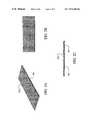
- FIGS. 1A–1Cillustrate three views of a laser capture microdissection (LCM) sample plate, representing an embodiment of the present invention
- FIGS. 2A–2Cillustrate three views of the sample plate shown in FIGS. 1A–1C after coating with a release agent, representing an embodiment of the present invention
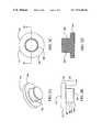
- FIGS. 3A–3Dillustrate four views of a sample carrier, representing an embodiment of the present invention
- FIGS. 4A–4Dillustrate four views of the sample carrier illustrated in FIGS. 3A–3D after an LCM film is added, representing an embodiment of the present invention
- FIGS. 5A–5Cillustrate three views of an assembly that includes four of the sample carriers depicted in FIGS. 4A–4D and one of the plates depicted in FIGS. 2A–2C , representing an embodiment of the present invention
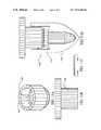
- FIGS. 6A–6Cillustrate three views of a completed assembly after vacuum hot cast molding, representing an embodiment of the present invention
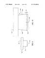
- FIGS. 7A–7Billustrate two sequential views of a laser capture microdissection film with molded features, representing an embodiment of the present invention
- FIG. 8illustrates a bottom view of a laser capture microdissection film with molded features, representing an embodiment of the present invention
- FIG. 9illustrates a side view of a laser capture microdissection apparatus, representing an embodiment of the invention.
- FIG. 10illustrates a side view of a microcentrifuge tube cap with a negative draft, representing an embodiment of the invention.
- FIGS. 11A–11Dillustrates a several views of a biological reaction vessel, representing an embodiment of the invention.
- plate 100is depicted.
- Plate 100can be fabricated from metal, glass, ceramic, or any other material suitable for the subsequent processing steps described below.
- plate 100is a glass microscope slide. It is important that the top surface 101 of plate 100 be flat.
- the depicted embodimentshows a bare microscope slide, the plate can be coated, or otherwise surface treated, in a preliminary processing step.
- FIGS. 2A–2Cthe plate 100 is depicted with a release agent 210 .
- the release agent 210is applied to the top surface 101 . It will be noted that the top surface 101 is obscured by the release agent 210 in FIGS. 2A–2B but is clearly visible as an interface in FIG. 2C .
- the release agentcan be any suitable nonadhesive material such as, for example, silicones, or TEFLON (i.e., polytetrafluoroethylene).
- the release coatingcan be a surfactant that increases the contact angle of liquids with which it comes in contact. It is important that the release agent 210 maintain and extend the flatness provided initially by the top surface 101 .
- the release agent 210can include a silicone containing surfactant agent such as, for example, RAIN-X.
- the sample carrier 300has an upper portion 310 and a lower portion 320 .
- the upper portion 310includes a top surface 315 and an outer perimeter 317 , and a shoulder 319 .
- the lower portion 320includes a flare 322 , an inner perimeter 324 , a taper 326 and a substrate surface 328 .
- the sample carrier 300can be a polymeric cap that is of transparent optical quality.
- the capcould be fabricated from polycarbonate, or other suitable optically transparent plastic.
- the capdoes not need to be optically transparent provided the absorption characteristics of the polymer from which it is made are compatible with suitable transmission of the laser energy to the capture film.
- a laser capture microdissection (LCM) transfer film 400is shown being applied to the sample carrier 300 .
- the laser capture microdissection transfer film 400can be applied to the bottom of a circular cap by punching a circular section from a free-standing sheet of ethylene vinyl acetate.
- the LCM transfer film 400can be molded to the bottom of the cap.
- the LCM transfer film 400can be deposited on the cap using a process such as spin coating, dipping, or spraying. In any event, manufacture of the consumable should be carried out in a sterile environment.
- the LCM transfer film 400be thin.
- a 50 micron thick filmis preferable to a 100 micron thick film.
- the filmcan advantageously be fabricated in thicknesses of approximately 500, 400, 300, 200, 100, 50 microns, or less.
- FIGS. 5A–5Ca plurality of combined sample carriers 300 together with their corresponding LCM transfer films 400 are depicted being lowered toward the release agent 210 that is coated on top of the plate 100 .
- the LCM transfer films 400can be an ethylene vinyl acetate (EVA) polymeric material.
- EVAethylene vinyl acetate
- FIGS. 6A–6Cthe assembly of four sample carriers 300 on plate 100 is depicted during the process step of vacuum hot baking.
- the process of vacuum hot bakingcauses the EVA to soften, melt and flow thereby conforming to the substantially planar surface presented by the release agent 210 .
- the flatness possessed by the plate 100is transferred to the LCM transfer film 400 . This also eliminates trapped air.
- the hot vacuum baking of the filmcan take place in moderate vacuum.
- the hot cast moldingtakes place at one torr and 95 degrees C. for approximately one hour.
- the LCM filminstead of attaching the LCM film to the base of the cap prior to its placement on top of the release agent coated plate, the LCM film can be coated on top of the release agent as a film layer.
- a sample carriercan then be placed on top of the LCM film.
- An assembly of one, or more, such combinationscan then be subjected to hot vacuum melt casting to planarize at least that portion of the LCM film that is located at the interface between the sample carrier and the release agent. In this way, when the sample carrier is removed from the plate, a portion of the planarized LCM film that corresponds with the bottom surface of the sample carrier will be broken away from the assembly together with the cap that is being removed. Those portions of the LCM film that are not adjacent the bottom of the cap being removed will remain on the plate.
- a twisting motionis applied to the sample carrier either before and/or during linear separation of the two prime components so as to exert a sheer force both within the LCM film and between the LCM film and the release layer.
- the release coatingcan be a silicone.
- the release coatingcan be a polytetrafluoroethylene.
- transfer film carriercan be substituted for the phrase “sample carrier.”
- sample carriercarries the transfer film. Only that portion of the sample that is transferred to the transfer film is carried by the carrier.
- the ethylene vinyl acetatecan be selected from among the available materials based on the following criteria.
- the ethylene vinyl acetateshould have a high melt index.
- a high melt indexis indicated by low viscosity and low molecular weight.
- the transfer filmis somewhat sticky but will not bind to everything with which it comes in contact.
- the capscan be made from clear plexiglass G (i.e., polymethyl methacrylate). By treating the glass slide with a surfactant before the caps are vacuum hot cast in place, the completed caps can be popped off the glass slide just before they are needed for acquisition of sample material.
- clear plexiglass Gi.e., polymethyl methacrylate
- the capis sized to fit in a standard microcentrifuge tube.
- the LCM transfer filmcan be attached to the cap using glue, or by welding the thermoplastic, or by some other mechanical means, holding the film in place.
- the side walls of the capcan have a negative draft. This negative draft can be machined into the tooling with which the caps are made.
- the capAfter capturing the tissue to be analyzed on the bottom of the cap, the cap is placed on the microcentrifuge tube containing proteinase (i.e., protease, e.g., Trypsin) solution and the tube is inverted. The tissue is then dissolved and the DNA is free to enter the solution. The solution is then pipetted out of the tube and into the PCR mixture.
- proteinasei.e., protease, e.g., Trypsin
- the EVA filmexpands both up and down when it is exposed to the energy from the laser. As an approximation, it is believed that the EVA film expands approximately 12–15% downward and upward when it is exposed to the LCM charge from the laser. The upward expansion is restricted by the plastic cap.
- the thickness of the LCM transfer filmshould be held to within 20%, preferably 5%.
- the bottom, exposed surface of the LCM transfer filmcan be termed a capture surface.
- the flatness of the LCM transfer filmshould be held to within approximately five microns, preferably approximately one micron.
- the flatness of the filmcan readily characterized based on the number of fringes multiplied by ⁇ /2.
- the flatness of the LCM transfer filmshould preferably be held to within two waves which is approximately equal to 1 ⁇ 4 micron per fringe, given a ⁇ of 540 nm.
- the dye in the ethylene vinyl acetateis what absorbs the laser energy.
- the ethylene vinyl acetatetransforms to a liquid phase, infuses into the cell structure of interest and then hardens.
- the particular manufacturing process used for fabricating the assemblyshould be inexpensive and reproducible. Conveniently, the fabrication of the present invention can be carried out by using any coating and baking method. It is preferred that the process be conducted in a contaminant-free environment. For the manufacturing operation, it is moreover an advantage to employ an automated method.
- the particular manufacturing process used for fabricating the assemblyis not essential to the present invention as long as it provides the described assembly. Normally those who make or use the invention will select the manufacturing process based upon tooling and energy requirements, the expected application requirements of the final product, and the demands of the overall manufacturing process.
- the particular material used for the capshould be biologically and chemically inert.
- the cap of the present inventioncan be made of any material with a melting point higher than that of EVA. It is preferred that the material be inexpensive.
- the capcan include polymethyl methacrylate. By proper selection of the polymeric materials, the cap can be solid. There is no need for a through-hole through the center axis of the cap.
- the particular material selected for the capis not essential to the present invention, as long as it provides the described function. Normally, those who make or use the invention will select the best commercially available material based upon the economics of cost and availability, the expected application requirements of the final product, and the demands of the overall manufacturing process.
- the LCM transfer filmcan be any suitable thermoplastic.
- the LCM transfer filmcan include one or more of: EVAs; polyurethanes (PU); polyvinyl acetates; ethylene-methyl acrylate (EMAC); polycarbonate (PC); ethylene-vinyl alcohol copolymers (EVOH); polypropylene (PP); and expandable or general purpose polystyrene (PS).
- EVAX 410, 200 and 205are suitable resins of EVA that are commercially available from DuPont wherein the operative variant is the amount of vinyl.
- the LCM transfer filmcan include an absorptive substance.
- the absorptive substancecan include an absorptive dye. This dye can be either a broad band absorptive dye or a frequency specific absorptive dye.
- the absorptive dyescan include one or more of: tin(IV) 2,3-naphthalocyanine dichloride; silicon(IV) 2,3-naphthalocyanine dihydroxide; silicon (IV) 2,3-naphthalocyanine dioctyloxide; and vanadyl 2,11,20,29-tetra-tert-butyl-2,3-naphthalocyanine.
- the absorptive substancecan include a plurality of Fullerines (i.e., Bucky Balls, e.g., C60).
- the LCM transfer filmcan also include a scattering media. Since the LCM transfer film is very close to the sample, the scattering media reduces shadows, thereby improving the process of imaging.
- the scattering mediacan include a diffusing material.
- the LCM transfer filmcan be loaded with a small particulate material that scatters the illumination light so as to minimize shadows and improve imaging without detrimentally effecting the LCM beam.
- the transfer filmcan include a dichromatic gelatin (DCG) to perform the same functions. The DCG can be exposed and developed to provide specific diffuser properties within the transfer film such as shaping.
- noncontact LCM transfer film and/or carrierThere are a variety of techniques for building a noncontact LCM transfer film and/or carrier.
- the purpose of the noncontact LCM approachis to provide a method for the elimination of problems associated with nonspecific binding of tissue to an LCM film.
- these portions of the samplecan be lifted mistakenly from the slide due to nonspecific attachment to the LCM film. That is, these areas stick to the film even though they were not illuminated by the laser. If these portions are transferred to the reagent vessel they will be digested by the reagents and appear as contaminants in the sample. It is important to prevent the loosely bound tissue areas from contacting the film.
- One method for preventing the contact of the film to areas of tissue that might nonspecifically transferis to offset (distance) the film a few microns from the tissue sample.
- the filmexpands roughly 10% of its thickness (about 5 to 10 microns based on a typical thickness of 50 to 100 microns) and contacts the tissue, thereby allowing transfer in the illuminated region. Outside this region, the film and tissue never come in contact because the film is spaced away from the tissue.
- the filmmust not be spaced too far from the tissue (greater than a few microns) since the film needs to contact the tissue after its expands due to the laser illumination.
- One technique to make a noncontact LCM transfer film that “stands-off” a few micronsis to create a series of pedestals that are a few microns high so as to provide a series of standoffs for the cap to rest on.
- These pedestalscan be created by exposing edges of the transfer film to the focused laser beam.
- the laser beamdistorts the normally flat film in the focal region raising the surface in this region.
- the height of these pedestalscan be adjusted by changing the power and pulse length of the focused laser beam.
- the diametercan be adjusted by changing the diameter of the laser beam.
- the exposure levelsare similar to the levels used for tissue transfer: approximately 10–90 mW for approximately 10–90 milliseconds. (To create the pedestals it may help to expose the film when it is in contact with a glass slide.)
- the reagent vialcan be constructed so that it has an internal rim that contacts the pedestals, sealing them from the reagent, thereby preventing tissue that might be on the pedestals from contaminating the sample.
- an LCM film 700can be provided with features 710 .
- the features 710can include a raised portion 720 (pedestal) and a protruding feature 730 (e.g., rim).
- the features 710can be molded (e.g., replicated), or otherwise formed (e.g., by laser), in the LCM film 700 .
- Such featuresgive the LCM film 700 a working surface that defines a topography.
- the purpose of the features 710is to provide an additional way of selecting single cells from a tissue sample using LCM, other than just a very small laser spot size.
- the features 710 that are fabricated into the LCM transfer filmcan be roughly the size of a desired cell 740 .
- the features 710can extend out from the film surface for a distance of several microns.
- the film 700itself can be offset from the cells a distance of from approximately 5 to approximately 10 microns by the protruding feature 730 that runs around the circumference of the cap. To stabilize the plane of the film, it will be appreciated that the protruding feature only needs to extend along at least three points of a perimeter of the film and does not need to be a continuous rim.
- the features 710can be fabricated by hot cast molding the LCM film 700 against a mold that has complimentary shapes of the features laser machined into the mold surface.
- a moldcan be made out of a polished metal surface or a glass surface using a Q-switched laser focused to a diameter of from approximately 5 to approximately 20 microns.
- the features 710can also be fabricated by molding the film against a mold surface that is micromachined with a diamond stylus. The topography is transferred from the mold to the film via replication.
- a protuberance (raised portion 720 ) for acquiring the desired cell 740can include a small raised area of LCM film roughly 5 to 20 microns in diameter.
- the raised portion 720will contact the tissue first and the laser power can be adjusted so that the surrounding adjacent film regions do not contact the tissue.
- the raised portion 720provides spatial discrimination in addition to the spatial discrimination provided by the position, size and mode of the laser beam.
- An advantage of the features 710is that a larger laser beam could be used and a researcher or laboratory technician could still achieve single cell lift-off.
- the raised portion of the film (raised portion 720 )will be heated to a higher temperature than the surrounding flat film area.
- the protruding feature 730(i.e., the rim) will not be heated. This would also increase the likelihood that a cell in the region of the feature would be captured exclusively. Of course, it is advantageous that raised portion 720 not protrude as far as protruding feature 730 .
- multiple pedestals 800could be molded into an LCM film 810 to allow multiple single cell lift off regions.
- the LCM film 810could again include a rim 820 . Multiple cells could then be analyzed in a single microcentrifuge tube.
- the structural featurei.e., spacer
- the structural featurethat holds the film away from the sample can be hot vacuum baked into the transfer film.
- a negative of the structural featurecan be formed in a plate.
- the structural featureis then replicated (as a positive) in the film when it is heated and flows into the void defined by the negative of the feature.
- the structural featurecan be formed in the transfer film with the use of a laser, or even with micro-machining equipment.
- the structural feature, or spacer,can be integrally formed in the laser capture microdissection transfer film.
- the structural featureprovides a separation between the transfer film and the sample. This separation holds the film away from the sample, thereby enabling noncontact laser capture microdissection.
- the transfer filmcan be connected to the substrate surface with a refractive index matching transparent fluid or glue.
- the transfer filmcan be coupled to the substrate surface by punching both the sample carrier and the transfer film from stock material simultaneously. It is even possible to couple the film to the carrier with double-sided tape.
- the laser capture microdissection transfer filmincludes a substantially planarized low land area.
- This low land areacan be provided with structural features that protrude so as to define a laser capture microdissection acquisition zone. These protrusions can be termed pedestals.
- the low landcan also be provided with structural features that hold most of the film away from the sample. In order to support the plane of the film, it is preferable to have at least three such supporting features. If these supporting features run around most, or all, of a perimeter of a transfer film, they can be termed a rim.
- the transfer filmWhen the transfer film is exposed to the electromagnetic energy, it expands (both up and down) against the substrate surface and contacts the tissue, thereby injecting itself into the sample. In the case where there is a space between the transfer film and the top surface of the sample, (noncontact laser capture microdissection) the expanding film will be projected through that space before it contacts the top surface of the sample at the beginning of the injection phase.
- FIG. 9a scatter illuminator design for an LCM device is illustrated.
- the purpose of the scatter illuminator designis to provide a more appropriate illuminator for an LCM microscope that generates a more even illumination to prevent shadows from obscuring internal cell structure.
- a laser capture microdissection apparatusincludes a top portion 910 and a bottom portion 920 .
- the top portion 910includes an upper surface to which a scattering media 930 can be coupled.
- the bottom portion 920includes a substrate surface to which a scattering media 940 can be coupled. Either, or both, of the scattering media 930 and 940 can be used.
- the scattering mediacan be incorporated into the transfer film carrier and/or the LCM transfer film.
- a scattering mediae.g., a piece of paper
- a scattering media of this typeeliminates the need for refractive index matching of the sample.
- Such a scattering mediacan allow visualization of the cell nucleus and other subcellular structures that would normally be obscured by normal illumination techniques.
- the scattering mediacan be a diffuser material.
- a diffuser material that is suitable for use as the scattering mediais milk glass which is a very dense, fine diffuser available from Edmund Scientific as Part No. P43,717. Standard laser printer/photocopier paper can even be used as the scattering media.
- Other types of transparent scattering mediacan be used, such as, for example, frosted glass, a lenticular sheet, a volume diffuser, and/or a surface diffuser.
- the scattering mediashould be a material that aggressively scatters the illumination light.
- a single sheet of typical ground glassis generally inadequate and needs to be combined in multiple layers as a serial stack of three or four sheets of ground glass to diffuse the illumination light sufficiently.
- the scattering mediacan be directly or indirectly connected to the transfer film carrier and/or the LCM transfer film.
- the scattering mediacan be formed on a surface of, or the interior of, the transfer film carrier and/or the LCM transfer film.
- the scattering mediacan be fabricated so as to shape the LCM beam and/or the illumination beam.
- the scattering medianeeds to be within a few millimeters of the sample to be effective. A few millimeters means less than one centimeter, preferably less than five millimeters.
- the apparatus 1000includes a top portion 1010 and a bottom portion 1020 .
- the bottom portion 1020includes a negative draft 1030 .
- the negative draft 1030is preferably approximately 5°.
- the bottom portion 1020also includes a chamfer 1040 .
- the chamfer 1040is preferably approximately 20°.
- the bottom portion 1020also includes a girdle 1050 .
- the width of the girdle 1050 for line contact with the interior of an analysis vesselis preferably approximately 0.01′′.
- Caps with a negative draftcan be fabricated with a break-apart plastic injection molding die. Alternatively, negative draft caps can be fabricated by interpolation with computer numeric control cutting tool machinery.
- a laser capture microdissection (LCM) biological reaction vessel 1100including an analysis vessel 1110 with an internal ridge and a cap 1120 with a transfer film 1130 .
- the transfer film 1130can include EVA and can have a stand-off rim 1150 .
- Stand-off rim 1150can be a 10–20 micron ridge providing a noncontact region in the center of the transfer film 1130 .
- the cap 1120is an integral portion of the biological reaction vessel 1100 .
- the analysis vessel 1110is formed to include an internal ridge 1140 .
- the internal ridgeslopes back toward an opening in the analysis vessel 1110 so as to make a tight seal with the cap 1120 , even if the stand-off rim is not present.
- the purpose of combining the internal ridge 1140 with the stand-off rim 1150 in a single embodimentis to provide an LCM analysis vessel and film carrier that have features to facilitate a noncontact method for positioning the transfer film over the tissue sample.
- the LCM non-contact methodreduces the probability that areas of tissue outside the focal adhesion region will be transferred. However, if the stand-off rim 1150 later comes in contact with the reaction, this advantage will be lost.
- the analysis vessel 1110 with this internal sealing featureallows the transfer film 1130 , with stand-off rim 1150 , to contact the tissue but not contact reaction fluid in the analysis vessel 1110 .
- the biological reaction vessel 1100includes the cap 1120 (lid) that can be removably coupled to the analysis vessel 1110 .
- the transfer film 1130is attached to the clear plastic cap 1120 .
- the transfer film 1130can be hot cast molded to include the stand-off rim 1150 that is 10 microns thicker than the central region of the cap 1120 .
- the stand-off rim 1150can be termed an annular rim.
- the transfer film 1130expands in the region of the focused laser beam and is able to bridge the 10 micron gap, thereby contacting the tissue and allowing transfer of a portion of the tissue to the film.
- This stand-off rim 1150can be termed a standoff region and acts as a spacer elevating the central region of the transfer film 1130 above the tissue and preventing the transfer film 1130 from contacting the tissue in this central region, until the LCM laser activate the transfer film 1130 .
- This stand-off region featurecan be molded into the transfer film 1130 by pressing the transfer film 1130 onto a heated plate that contains an inverse image of this step (spacer) feature. This method replicates the feature.
- a moldcould be constructed using a polished metal plate and standard chemical etching techniques. It could also be manufactured using glass or silicon substrates and chemical etching. Alternatively, a diamond lathe could be used to machine this feature onto a suitable metal substrate (e.g., copper, aluminum, steel, etc.).
- the cap 1120 that seals the liquid reagent analysis vessel 1110can be made out of inert plastic such as polypropylene or polyethylene.
- the analysis vessel 1110has the internal ridge 1140 (step) that is designed to mate with and cover the annular rim of the cap 1120 providing a tight seal at this point. This seal prevents liquids in the analysis vessel 1110 from contacting the bottom surface of the rim of the cap.
- This designeliminates nonspecific tissue transfer since the stand-off rim 1150 is the only area of the cap 1120 that contacts the tissue (other than the desired transfer regions illuminated by the laser) and the digestion reagents in the analysis vessel 1110 never contact this region (stand-off rim 1150 ).
- the internal ridge 1140 feature in the analysis vesselcan be designed with a slight angle so as to partially cut into the Transfer film 1130 providing a very tight seal similar to vacuum flange sealing techniques.
- a slight bulge or indentationcan be molded into the barrel of the cap 1120 or into the top portion of the analysis vessel 1110 so as to provide a downward directed force and a positive seal between the cap 1120 and the analysis vessel 1110 .
- a glass microscope slideis first cleaned. Then the glass microscope slide is spray coated with a thin layer of a commercially available silicone release agent, in this example a silicone containing surfactant that is readily commercially available (i.e., RAINEX). Meanwhile, a supply of sample carriers in the form of microcentrifuge tube caps are molded from plexiglass G. Cylindrical chips of LCM film punched from a sheet of ethylene vinyl acetate (EVA) are then attached to the bottom surface of the caps, optionally with an epoxy adhesive. The resultant cap subassemblies are then placed on top of the release agent coated glass subassembly for hot vacuum baking.
- a commercially available silicone release agentin this example a silicone containing surfactant that is readily commercially available (i.e., RAINEX).
- a supply of sample carriers in the form of microcentrifuge tube capsare molded from plexiglass G. Cylindrical chips of LCM film punched from a sheet of ethylene vinyl a
- the hot vacuum bakingis carried out at a pressure of approximately one torr or less at a temperature of 95° C. for approximately one hour. This planarizes the transfer film.
- the baked assemblyis then allowed to cool to room temperature.
- the resulting assemblycan include a planoconcave void located between each of the caps and the underlying plate. In this way only the perimeter of the bottom of the caps is in contact with the glass plate.
- Thisprovides two significant advantages. First, the working surface of the LCM film is spaced apart from the glass slide in a vacuum and remains free of surface damage and contaminants. Second, the removal of each cap from the glass slide is facilitated by the fact that only a fraction of the surface area of the bottom of the cap is attached to the release layer that has been coated on the glass slide. Therefore, removal of the cap from the slide requires much less force than if the entire lower surface of the cap were in contact with the release layer.
- the completed consumable productscan be sterilized (e.g., with beta or gamma radiation). Finally, the completed consumable products should be subjected to a rigorous quality assurance inspection.
- a practical application of the present invention that has value within the technological artsis the collection of a large database of gene expression patterns of both healthy and diseased tissue, at different stages of diseases.
- This databasewill be used to more fully understand that pathogenesis of cancer and infectious diseases.
- the present inventionwill enable a scientist to identify gene patterns and incorporate this information into effective diagnostics for disease.
- the present inventionwill allow medical doctors to compare actual patient tissue samples with archived data from patient samples at different disease stages, thereby allowing them to prescribe more effective stage therapies, eliminate unnecessary procedures, and reduce patient suffering.
- Other research areas where the present invention will find useare drug discovery, developmental biology, forensics, botany, and the study of infectious diseases such a drug-resistant tuberculosis. There are virtually innumerable uses for the present invention, all of which need not be detailed here.
- Laser capture microdissectionrepresenting an embodiment of the invention can be cost effective and advantageous for at least the following reasons.
- the present inventionwill replace current methods with better technology that allows for more accurate and reproducible results.
- the present inventioncan be used to provide a low cost injection molded polymer disposable that integrates a laser capture microdissection film into the interior surface of an analysis container such as a microcentrifuge tube.
- the individual componentsneed not be formed in the disclosed shapes, or assembled in the disclosed configuration, but could be provided in virtually any shape, and assembled in virtually any configuration. Further, the individual components need not be fabricated from the disclosed materials, but could be fabricated from virtually any suitable materials. Further, although the caps and cap assemblies disclosed herein are described as a physically separate module, it will be manifest that the caps and cap assemblies may be integrated into other apparatus with which they are associated. Furthermore, all the disclosed elements and features of each disclosed embodiment can be combined with, or substituted for, the disclosed elements and features of every other disclosed embodiment except where such elements or features are mutually exclusive.
Landscapes
- Physics & Mathematics (AREA)
- Health & Medical Sciences (AREA)
- Life Sciences & Earth Sciences (AREA)
- Chemical & Material Sciences (AREA)
- Analytical Chemistry (AREA)
- Biochemistry (AREA)
- General Health & Medical Sciences (AREA)
- General Physics & Mathematics (AREA)
- Immunology (AREA)
- Pathology (AREA)
- Sampling And Sample Adjustment (AREA)
Abstract
Description
Claims (76)
Priority Applications (15)
| Application Number | Priority Date | Filing Date | Title |
|---|---|---|---|
| US08/984,979US7075640B2 (en) | 1997-10-01 | 1997-12-04 | Consumable for laser capture microdissection |
| EP98950746AEP1021700B1 (en) | 1997-10-01 | 1998-09-30 | Consumable for laser capture microdissection |
| DE69821508TDE69821508T2 (en) | 1997-10-01 | 1998-09-30 | CONSUMPTION UNIT FOR LASER STICKING MICRODISECTION |
| AT02027060TATE500496T1 (en) | 1997-10-01 | 1998-09-30 | METHOD FOR LASER ATTACHMENT MICRODISCISSION |
| CA002306030ACA2306030C (en) | 1997-10-01 | 1998-09-30 | Consumable for laser capture microdissection |
| HK01100380.7AHK1029623B (en) | 1997-10-01 | 1998-09-30 | Consumable for laser capture microdissection |
| PCT/US1998/020340WO1999017094A2 (en) | 1997-10-01 | 1998-09-30 | Consumable for laser capture microdissection |
| DE69842157TDE69842157D1 (en) | 1997-10-01 | 1998-09-30 | Method for laser attachment microdissection |
| AU96718/98AAU9671898A (en) | 1997-10-01 | 1998-09-30 | Consumable for laser capture microdissection |
| JP2000514115AJP4125481B2 (en) | 1997-10-01 | 1998-09-30 | Consumables for laser capture microdissection |
| EP02015774.9AEP1260807B1 (en) | 1997-10-01 | 1998-09-30 | Consumable for laser capture microdissection |
| EP02027060AEP1304556B1 (en) | 1997-10-01 | 1998-09-30 | A method for performing laser capture microdissection |
| AT98950746TATE259057T1 (en) | 1997-10-01 | 1998-09-30 | CONSUMABLE UNIT FOR LASER ATTACHMENT - MICRO DISSECTION |
| US11/276,887US7221447B2 (en) | 1997-10-01 | 2006-03-17 | Consumable for laser capture microdissection |
| JP2008039148AJP4423482B2 (en) | 1997-10-01 | 2008-02-20 | Consumables for laser capture microdissection |
Applications Claiming Priority (2)
| Application Number | Priority Date | Filing Date | Title |
|---|---|---|---|
| US6073297P | 1997-10-01 | 1997-10-01 | |
| US08/984,979US7075640B2 (en) | 1997-10-01 | 1997-12-04 | Consumable for laser capture microdissection |
Related Child Applications (1)
| Application Number | Title | Priority Date | Filing Date |
|---|---|---|---|
| US11/276,887DivisionUS7221447B2 (en) | 1997-10-01 | 2006-03-17 | Consumable for laser capture microdissection |
Publications (2)
| Publication Number | Publication Date |
|---|---|
| US20010038449A1 US20010038449A1 (en) | 2001-11-08 |
| US7075640B2true US7075640B2 (en) | 2006-07-11 |
Family
ID=36640985
Family Applications (2)
| Application Number | Title | Priority Date | Filing Date |
|---|---|---|---|
| US08/984,979Expired - Fee RelatedUS7075640B2 (en) | 1997-10-01 | 1997-12-04 | Consumable for laser capture microdissection |
| US11/276,887Expired - Fee RelatedUS7221447B2 (en) | 1997-10-01 | 2006-03-17 | Consumable for laser capture microdissection |
Family Applications After (1)
| Application Number | Title | Priority Date | Filing Date |
|---|---|---|---|
| US11/276,887Expired - Fee RelatedUS7221447B2 (en) | 1997-10-01 | 2006-03-17 | Consumable for laser capture microdissection |
Country Status (1)
| Country | Link |
|---|---|
| US (2) | US7075640B2 (en) |
Cited By (11)
| Publication number | Priority date | Publication date | Assignee | Title |
|---|---|---|---|---|
| US20020001837A1 (en)* | 2000-04-26 | 2002-01-03 | Baer Thomas M. | Laser capture microdissection (LCM) extraction device and device carrier, and method for post-LCM fluid processing |
| US20050266172A1 (en)* | 2004-05-27 | 2005-12-01 | Eastman Kodak Company | Linear laser light beam for making OLEDS |
| US20090272186A1 (en)* | 2008-05-05 | 2009-11-05 | Core Laboratories Lp | Enhanced process for preparing core sample thin sections |
| US20130214154A1 (en)* | 2010-09-02 | 2013-08-22 | Wayne State University | System and method for ionization of molecules for mass spectrometry and ion mobility spectrometry |
| US8715955B2 (en) | 2004-09-09 | 2014-05-06 | Life Technologies Corporation | Laser microdissection apparatus and method |
| US8722357B2 (en) | 2001-11-05 | 2014-05-13 | Life Technologies Corporation | Automated microdissection instrument |
| US9177773B2 (en) | 2010-10-25 | 2015-11-03 | Wayne State University | Systems and methods extending the laserspray ionization mass spectrometry concept from atmospheric pressure to vacuum |
| US20160025690A1 (en)* | 2013-03-11 | 2016-01-28 | Shimadzu Corporation | Flow path switching valve |
| WO2017027627A1 (en) | 2015-08-10 | 2017-02-16 | Life Technologies Corporation | Biological sample preparation for testing |
| US9824872B2 (en) | 2010-09-02 | 2017-11-21 | Wayne State University | Systems and methods for high throughput solvent assisted ionization inlet for mass spectrometry |
| US10156501B2 (en) | 2001-11-05 | 2018-12-18 | Life Technologies Corporation | Automated microdissection instrument for determining a location of a laser beam projection on a worksurface area |
Families Citing this family (6)
| Publication number | Priority date | Publication date | Assignee | Title |
|---|---|---|---|---|
| US7556733B2 (en)* | 2001-06-15 | 2009-07-07 | Mds Analytical Technologies (Us) Inc. | Low volume filtration column devices and methods of filtering therewith |
| US7456938B2 (en)* | 2003-11-07 | 2008-11-25 | Mds Analytical Technologies (Us) Inc. | Laser microdissection on inverted polymer films |
| US20080220039A1 (en)* | 2004-09-17 | 2008-09-11 | Sherman Darren R | Thin Film Medical Devices Manufactured on Application Specific Core Shapes |
| US8383378B2 (en)* | 2005-10-10 | 2013-02-26 | The Regents Of The University Of California | Micro-bubble plate for patterning biological and non-biological materials |
| KR101721349B1 (en)* | 2012-12-17 | 2017-03-29 | 내셔널 타이완 유니버시티 | Sampling assembly, microscope module, and microscope apparatus |
| CA3197977A1 (en)* | 2020-11-11 | 2022-05-19 | Lance A. Liotta | Laser capture microdissection visualization chemistry |
Citations (195)
| Publication number | Priority date | Publication date | Assignee | Title |
|---|---|---|---|---|
| US2801568A (en) | 1954-11-15 | 1957-08-06 | Evelyn S Dakin | Microscope slide |
| US3680947A (en) | 1970-04-21 | 1972-08-01 | Western Electric Co | Microscope apparatus with movable fluid bearing object support |
| US3684099A (en)* | 1970-07-21 | 1972-08-15 | Carl T Kiebach | Assembly element for press |
| US3705769A (en) | 1970-11-12 | 1972-12-12 | Johannsmeier Karl Heinz | Optical alignment and contact printing system with improved chuck assembly |
| GB1317803A (en) | 1969-07-31 | 1973-05-23 | Siemens Ag | Specimen vessels and closure caps therefor |
| US3836231A (en) | 1971-09-30 | 1974-09-17 | Gen Electric | Uniform liquid crystal cells and method for making the same |
| US3848962A (en) | 1973-10-18 | 1974-11-19 | Coulter Electronics | Slide mounting apparatus for microscopy |
| US3939019A (en) | 1974-08-02 | 1976-02-17 | Pickett John E P | Covering apparatus and method for film mounted serial tissue sections |
| US3995941A (en)* | 1972-03-14 | 1976-12-07 | Asahi Glass Co., Ltd. | Liquid crystal cells |
| US4064205A (en) | 1974-07-02 | 1977-12-20 | Logetronics, Inc. | Method for making a printing plate from a porous substrate |
| US4080476A (en) | 1976-11-15 | 1978-03-21 | Datascope Corporation | Anti-fog coated optical substrates |
| US4149803A (en) | 1975-05-23 | 1979-04-17 | Litz Per Erik | Composite petrographic thin section slide and method of making same |
| US4205059A (en) | 1977-03-09 | 1980-05-27 | Hagens Gunther Von | Animal and vegetal tissues permanently preserved by synthetic resin impregnation |
| US4210384A (en) | 1976-09-11 | 1980-07-01 | Carl Zeiss-Stiftung | Inverted-design optical microscope |
| US4245003A (en) | 1979-08-17 | 1981-01-13 | James River Graphics, Inc. | Coated transparent film for laser imaging |
| US4302480A (en) | 1978-06-16 | 1981-11-24 | Merck Patent Gesellschaft Mit Beschrankter Haftung | Thin cover sheet for use in microscopic staining and a process for its production |
| US4303866A (en) | 1979-06-12 | 1981-12-01 | Costruzioni Aeronautiche Giovanni Agusta S.P.A. | Method and device for mounting pieces inside the vacuum chamber of an electron microscope |
| US4320157A (en) | 1980-08-08 | 1982-03-16 | Hagens Gunther Von | Method for preserving large sections of biological tissue with polymers |
| US4333983A (en) | 1980-04-25 | 1982-06-08 | Optical Coating Laboratory, Inc. | Optical article and method |
| EP0081976A1 (en) | 1981-12-11 | 1983-06-22 | Sterilin Limited | Piercable closures for sample bottles |
| US4436385A (en) | 1980-07-25 | 1984-03-13 | Carl-Zeiss-Stiftung | Specimen holder for inverted microscopes |
| US4467915A (en) | 1980-08-20 | 1984-08-28 | Snyder Robert G | Emulsion package and method of mixing the emulsion |
| US4497792A (en) | 1981-12-18 | 1985-02-05 | Sherwood Medical Company | Specimen embedding composition |
| US4508435A (en) | 1982-06-18 | 1985-04-02 | Coulter Electronics, Inc. | Air vacuum chuck for a microscope |
| US4509834A (en) | 1982-03-24 | 1985-04-09 | Hodgson R W | Positioning apparatus for positioning a workpiece relative to a frame of reference |
| US4538885A (en) | 1982-06-18 | 1985-09-03 | Coulter Electronics, Inc. | Optical microscope system |
| US4552033A (en) | 1980-07-08 | 1985-11-12 | Gebr. Marzhauser Wetzlar oHG | Drive system for a microscope stage or the like |
| US4588674A (en) | 1982-10-14 | 1986-05-13 | Stewart Malcolm J | Laser imaging materials comprising carbon black in overlayer |
| US4588579A (en) | 1982-10-19 | 1986-05-13 | Rolf Bachhuber | Process for the production of thin sections of biological tissue |
| US4600282A (en) | 1983-11-14 | 1986-07-15 | Canon Kabushiki Kaisha | Alignment apparatus |
| US4614431A (en) | 1983-02-18 | 1986-09-30 | Hitachi, Ltd. | Alignment apparatus with optical length-varying optical system |
| US4624915A (en) | 1982-07-29 | 1986-11-25 | Board Of Trustees Of Michigan State University | Positive selection sorting of cells |
| US4627009A (en) | 1983-05-24 | 1986-12-02 | Nanometrics Inc. | Microscope stage assembly and control system |
| US4629687A (en) | 1982-07-29 | 1986-12-16 | Board Of Trustees Of Michigan State University | Positive selection sorting of cells |
| US4673261A (en) | 1985-05-16 | 1987-06-16 | Alessi Industries, Inc. | Motion control apparatus for precise repeatable positioning |
| US4684781A (en) | 1985-01-29 | 1987-08-04 | Physical Sciences, Inc. | Method for bonding using laser induced heat and pressure |
| US4702565A (en) | 1985-03-07 | 1987-10-27 | Carl-Zeiss-Stiftung | Cross-slide stage for a microscope |
| US4731530A (en) | 1986-04-21 | 1988-03-15 | Mikan Peter J | Joystick control having optical sensors |
| US4743463A (en) | 1986-02-21 | 1988-05-10 | Eastman Kodak Company | Method for forming patterns on a substrate or support |
| US4752455A (en) | 1986-05-27 | 1988-06-21 | Kms Fusion, Inc. | Pulsed laser microfabrication |
| US4756922A (en) | 1986-05-12 | 1988-07-12 | Freund Industrial Co., Ltd. | Powder coating method |
| US4784873A (en) | 1983-05-30 | 1988-11-15 | Arthur Pfeiffer Vakuumtechnik Wetzlar Gmbh | Method of producing biological specimens |
| US4807984A (en) | 1986-02-18 | 1989-02-28 | Hitachi, Ltd. | Apparatus and method for specimen inspection |
| US4824229A (en) | 1986-04-09 | 1989-04-25 | Sapporo Breweries, Ltd. | Microscope with automatic sweeping device |
| US4836667A (en) | 1986-05-06 | 1989-06-06 | Slidex Corporation | Microscope |
| US4839194A (en) | 1985-07-05 | 1989-06-13 | Bone Diagnostic Center | Methods of preparing tissue samples |
| US4852985A (en) | 1986-10-16 | 1989-08-01 | Olympus Optical Co., Ltd. | Illuminating device for microscopes |
| US4856873A (en) | 1987-05-15 | 1989-08-15 | Storz Instrument Company | Documentation illumination module |
| US4871245A (en) | 1986-10-27 | 1989-10-03 | Olympus Optical Co., Ltd. | Surgical microscope |
| US4895735A (en) | 1988-03-01 | 1990-01-23 | Texas Instruments Incorporated | Radiation induced pattern deposition |
| US4906494A (en) | 1985-10-09 | 1990-03-06 | The Dow Chemical Company | Antistatic sheet material, package and method of making |
| US4911782A (en) | 1988-03-28 | 1990-03-27 | Cyto-Fluidics, Inc. | Method for forming a miniaturized biological assembly |
| US4920053A (en) | 1984-03-29 | 1990-04-24 | Olympus Optical Co., Ltd. | Method for micromanipulating cells by moving cell-containing vessel on stage of inverted microscope while pricking cells with tip of stylus |
| US4923294A (en) | 1988-10-20 | 1990-05-08 | Micron Technology, Inc. | Lead frame holding device |
| US4954715A (en) | 1989-06-26 | 1990-09-04 | Zoeld Tibor | Method and apparatus for an optimized multiparameter flow-through particle and cell analyzer |
| US4964708A (en) | 1989-07-14 | 1990-10-23 | Mason Michael S | Microscope for medical surgery |
| US4987006A (en) | 1990-03-26 | 1991-01-22 | Amp Incorporated | Laser transfer deposition |
| EP0409550A1 (en) | 1989-07-18 | 1991-01-23 | Ethicon, Inc. | Polymeric liquid dressing for skin |
| US4992660A (en) | 1989-06-26 | 1991-02-12 | Jeol Ltd. | Scanning tunneling microscope |
| US5017428A (en) | 1987-02-07 | 1991-05-21 | Pelikan Aktiengesellschaft | Multiple impression thermal transfer ribbon |
| WO1991007683A1 (en) | 1989-11-09 | 1991-05-30 | Insystems, Inc. | Specimen review station |
| US5023187A (en) | 1985-09-13 | 1991-06-11 | Fisher Scientific Company | Method and device for accelerated treatment of thin sample on surface |
| US5029791A (en) | 1990-03-08 | 1991-07-09 | Candela Laser Corporation | Optics X-Y positioner |
| US5057689A (en) | 1989-09-20 | 1991-10-15 | Matsushita Electric Industrial Co., Ltd. | Scanning electron microscope and a method of displaying cross sectional profiles using the same |
| US5077620A (en) | 1990-06-06 | 1991-12-31 | George Mauro | Motorized optical component positioning stage |
| US5089909A (en) | 1987-05-15 | 1992-02-18 | Storz Instrument Company | Documentation illumination module for a microscope system |
| US5103338A (en) | 1990-10-04 | 1992-04-07 | Crowley Kevin D | Apparatus for positioning objects for microscopic examination |
| US5126877A (en) | 1990-09-08 | 1992-06-30 | Carl-Zeiss-Stiftung | Illumination system for a surgical microscope |
| US5132129A (en) | 1989-08-18 | 1992-07-21 | Lrc Products Limited | Production of thin walled hollow polyurethane articles and polyurethane coatings on substrates |
| US5143552A (en) | 1988-03-09 | 1992-09-01 | Tokyo Electron Limited | Coating equipment |
| US5158895A (en) | 1990-03-30 | 1992-10-27 | Fujirebio Inc. | Automatic immunological measuring system |
| US5162941A (en) | 1991-07-23 | 1992-11-10 | The Board Of Governors Of Wayne State University | Confocal microscope |
| US5165297A (en) | 1991-02-15 | 1992-11-24 | Albert Einstein College Of Medicine Of Yeshiva University, A Div. Of Yeshiva Univ. | Remote controlled micromanipulator |
| US5173802A (en) | 1990-09-19 | 1992-12-22 | Carl-Zeiss-Stiftung | Counterbalanced supporting frame for a surgical microscope |
| US5173803A (en) | 1990-09-19 | 1992-12-22 | Carl-Zeiss-Stiftung | Pivoting device for supporting frames for optical observation equipment |
| US5192503A (en) | 1990-05-23 | 1993-03-09 | Mcgrath Charles M | Probe clip in situ assay apparatus |
| US5202230A (en) | 1990-09-07 | 1993-04-13 | Kamentsky Louis A | Methods of detecting cut cells in a tissue section |
| US5217768A (en) | 1991-09-05 | 1993-06-08 | Advanced Dielectric Technologies | Adhesiveless susceptor films and packaging structures |
| US5221698A (en) | 1991-06-27 | 1993-06-22 | The Regents Of The University Of Michigan | Bioactive composition |
| US5225326A (en) | 1988-08-31 | 1993-07-06 | Research Development Foundation | One step in situ hybridization assay |
| US5253110A (en) | 1988-12-22 | 1993-10-12 | Nikon Corporation | Illumination optical arrangement |
| US5262891A (en) | 1991-04-30 | 1993-11-16 | Olympus Optical Co., Ltd. | Optical microscope of the transmission type |
| US5263384A (en) | 1991-02-20 | 1993-11-23 | Olympus Optical Co., Ltd. | Moving stage |
| US5280384A (en) | 1988-11-09 | 1994-01-18 | Senko Medical Instrument Mfg. Co., Ltd. | Semitransparent slide, and filter combination for a microscope |
| WO1994002646A1 (en) | 1992-07-17 | 1994-02-03 | Aprogenex Inc. | Enriching and identyfying fetal cells in maternal blood for in situ hybridization |
| US5288996A (en) | 1990-11-19 | 1994-02-22 | At&T Bell Laboratories | Near-field optical microscopic examination of genetic material |
| US5292559A (en) | 1992-01-10 | 1994-03-08 | Amp Incorporated | Laser transfer process |
| US5296291A (en) | 1989-05-05 | 1994-03-22 | W. R. Grace & Co.-Conn. | Heat resistant breathable films |
| US5296963A (en) | 1991-02-27 | 1994-03-22 | Hitachi, Ltd. | Apparatus and method for applying a laser beam through a microscope |
| US5300540A (en) | 1990-09-04 | 1994-04-05 | Masters Thomas R | Preserved cellular structures |
| US5312393A (en) | 1992-12-31 | 1994-05-17 | Douglas Mastel | Ring lighting system for microsurgery |
| US5323009A (en) | 1990-04-06 | 1994-06-21 | Harris Martin R | Conforcal microscope |
| US5337178A (en) | 1992-12-23 | 1994-08-09 | International Business Machines Corporation | Titlable optical microscope stage |
| US5345333A (en) | 1991-04-19 | 1994-09-06 | Unimat (Usa) Corporation | Illumination system and method for a high definition light microscope |
| US5346765A (en) | 1990-02-06 | 1994-09-13 | Sumitono Bakelite Company Limited | Cover tape for packaging chip type electronic parts |
| US5349436A (en) | 1992-12-02 | 1994-09-20 | Harry Fisch | Biological assembly |
| US5357366A (en) | 1992-12-08 | 1994-10-18 | Marchlenski Stanley P | Mechanical stage adjustment mechanism |
| US5359417A (en) | 1991-10-18 | 1994-10-25 | Carl-Zeiss-Stiftung | Surgical microscope for conducting computer-supported stereotactic microsurgery and a method for operating the same |
| US5367401A (en) | 1990-11-23 | 1994-11-22 | Perceptive Scientific Instruments, Inc. | Microscope slide rotary stage |
| EP0388168B1 (en) | 1989-03-16 | 1994-12-14 | Johnson & Johnson Clinical Diagnostics, Inc. | Incubator |
| US5378675A (en) | 1991-11-05 | 1995-01-03 | Konica Corporation | Thermal transfer recording image receiving sheet |
| US5386112A (en) | 1990-06-29 | 1995-01-31 | Dixon; Arthur E. | Apparatus and method for transmitted-light and reflected-light imaging |
| US5391329A (en) | 1993-08-23 | 1995-02-21 | Hughes Aircraft Company | Process for making a solid optical limiter containing a graded distribution of reverse saturable material |
| US5393647A (en) | 1993-07-16 | 1995-02-28 | Armand P. Neukermans | Method of making superhard tips for micro-probe microscopy and field emission |
| US5403970A (en) | 1989-11-21 | 1995-04-04 | Yamaha Corporation | Electrical musical instrument using a joystick-type control apparatus |
| US5412503A (en) | 1992-08-27 | 1995-05-02 | U.S. Philips Corporation | Specimen holder for a particle beam optical apparatus |
| US5416131A (en) | 1992-06-10 | 1995-05-16 | Uno Plast A/S | Article with a coating having friction-reducing properties in wet condition as well as a method for the production of such a coated article |
| US5420716A (en) | 1992-07-01 | 1995-05-30 | Olympus Optical Co., Ltd. | Surgical microscope apparatus |
| US5427950A (en)* | 1992-01-18 | 1995-06-27 | Kabushiki Kaisha Seitai Kagaku Kankyusho | Method for radioactivity measurement, process for preparing sample and device therefor |
| US5434703A (en) | 1991-10-09 | 1995-07-18 | Fuji Photo Optical Co., Ltd. | Binocular stereomicroscope |
| WO1995023960A1 (en) | 1994-03-01 | 1995-09-08 | Government Of The United States, Represented By The Secretary Of The Department Of Health And Human Services | Isolation of cellular material under microscopic visualization |
| US5450233A (en) | 1992-04-28 | 1995-09-12 | Olympus Optical Co., Ltd. | Microscope having Y-shaped frame structure |
| US5455420A (en) | 1994-07-12 | 1995-10-03 | Topometrix | Scanning probe microscope apparatus for use in a scanning electron |
| WO1995030919A1 (en) | 1994-05-09 | 1995-11-16 | The Regents Of The University Of California | Illuminator elements for conventional light microscopes |
| US5468967A (en) | 1994-08-26 | 1995-11-21 | National University Of Singapore | Double reflection cathodoluminescence detector with extremely high discrimination against backscattered electrons |
| US5471260A (en) | 1994-10-28 | 1995-11-28 | Leica Inc. | Joystick for an ophthalmic instrument where vertical movement is controlled by rotating the joystick |
| US5479252A (en) | 1993-06-17 | 1995-12-26 | Ultrapointe Corporation | Laser imaging system for inspection and analysis of sub-micron particles |
| US5486335A (en) | 1992-05-01 | 1996-01-23 | Trustees Of The University Of Pennsylvania | Analysis based on flow restriction |
| US5492837A (en) | 1993-08-27 | 1996-02-20 | Biogenex Laboratories | Mounting medium for microscope slide preparations |
| US5492861A (en) | 1992-09-03 | 1996-02-20 | Deutsche Forschungsanstalt Fuer Luft-Und Raumfahrt E.V. | Process for applying structured layers using laser transfer |
| US5493861A (en) | 1991-08-19 | 1996-02-27 | Danfoss A/S | Hydraulic system with pump and load |
| US5494646A (en) | 1993-04-14 | 1996-02-27 | Seymour; Eugene H. | Sampling device and sample adequacy system |
| US5504366A (en) | 1992-07-17 | 1996-04-02 | Biotechnology Research And Development Corp. | System for analyzing surfaces of samples |
| US5506725A (en) | 1994-12-28 | 1996-04-09 | Koike Seiki Co., Ltd. | Transmission type confocal laser microscope |
| US5513768A (en) | 1992-07-20 | 1996-05-07 | Smith; James C. | Sealing cap for containers |
| US5517353A (en) | 1993-05-28 | 1996-05-14 | Nikon Corporation | Illuminating apparatus for a microscope |
| WO1996016517A1 (en) | 1994-11-22 | 1996-05-30 | Unisys Corporation | Extracting and processing data derived from a common channel signalling network |
| US5529841A (en) | 1994-09-29 | 1996-06-25 | The United States Of America As Represented By The Secretary Of The Navy | Hydrogen sulfide analyzer with protective barrier |
| US5531997A (en) | 1992-05-29 | 1996-07-02 | The Regents Of University Of California | Coated transplant and method for making same |
| US5532873A (en) | 1993-09-08 | 1996-07-02 | Dixon; Arthur E. | Scanning beam laser microscope with wide range of magnification |
| US5532476A (en) | 1994-12-21 | 1996-07-02 | Mikan; Peter J. | Redundant indicator for detecting neutral position of joystick member |
| US5532128A (en) | 1991-11-19 | 1996-07-02 | Houston Advanced Research Center | Multi-site detection apparatus |
| US5535052A (en) | 1992-07-24 | 1996-07-09 | Carl-Zeiss-Stiftung | Laser microscope |
| US5536941A (en) | 1995-02-22 | 1996-07-16 | Gatan, Inc. | Rotatable wide angle camera and prism assembly for electron microscopes |
| US5537863A (en) | 1993-07-15 | 1996-07-23 | Nikon Corporation | Scanning probe microscope having a cantilever used therein |
| US5541064A (en) | 1985-11-04 | 1996-07-30 | Cell Analysis Systems, Inc. | Methods and apparatus for immunoploidy analysis |
| US5552928A (en) | 1991-10-30 | 1996-09-03 | Nikon Corporation | Microscope with movable stage and objective for examining large sample |
| US5557456A (en) | 1994-03-04 | 1996-09-17 | Oncometrics Imaging Corp. | Personal interface device for positioning of a microscope stage |
| US5556790A (en) | 1994-12-05 | 1996-09-17 | Pettit; John W. | Method for Automated DNA sequencing |
| US5559329A (en) | 1994-08-31 | 1996-09-24 | Touchstone Research Laboratory, Ltd. | Scanning electron microscope fiber push-out apparatus and method |
| US5558329A (en) | 1995-03-01 | 1996-09-24 | Liu; William S. Y. | Photoelectric digitized joystick |
| US5574077A (en) | 1992-04-17 | 1996-11-12 | Dougherty; Thomas K. | Microwave-absorbing materials containing polar icosahedral molecular units and methods of making the same |
| US5578832A (en) | 1994-09-02 | 1996-11-26 | Affymetrix, Inc. | Method and apparatus for imaging a sample on a device |
| US5580612A (en) | 1992-08-06 | 1996-12-03 | Hoechst Aktiengesellschaft | Process for production of layer element containing at least one monomolecular layer of an amphiphilic molecule and one fullerene |
| WO1996040435A1 (en) | 1995-06-07 | 1996-12-19 | Becton Dickinson And Company | Device and method for phage-based antibiotic susceptibility testing |
| US5587748A (en) | 1994-10-28 | 1996-12-24 | Leica Inc. | Joystick override control for an ophthalmic instrument |
| US5587833A (en) | 1993-07-09 | 1996-12-24 | Compucyte Corporation | Computerized microscope specimen encoder |
| US5598888A (en) | 1994-09-23 | 1997-02-04 | Grumman Aerospace Corporation | Cryogenic temperature gradient microscopy chamber |
| US5621207A (en) | 1994-08-29 | 1997-04-15 | Hasbro, Inc. | Optical joystick using a plurality of multiplexed photoemitters and a corresponding photodetector |
| US5621619A (en)* | 1990-10-25 | 1997-04-15 | Cts Corporation | All ceramic surface mount sip and dip networks having spacers and solder barriers |
| WO1997013838A1 (en) | 1995-10-10 | 1997-04-17 | The Government Of The United States Of America, Represented By The Secretary, Department Of Health And Human Services | Isolation of cellular material under microscopic visualization |
| US5631734A (en) | 1994-02-10 | 1997-05-20 | Affymetrix, Inc. | Method and apparatus for detection of fluorescently labeled materials |
| US5633535A (en)* | 1995-01-27 | 1997-05-27 | Chao; Clinton C. | Spacing control in electronic device assemblies |
| US5638206A (en) | 1993-09-29 | 1997-06-10 | Ushiodenki Kabushiki Kaisha | Confocal optical microscope and length measuring device using this microscope |
| US5639428A (en) | 1994-07-19 | 1997-06-17 | Becton Dickinson And Company | Method and apparatus for fully automated nucleic acid amplification, nucleic acid assay and immunoassay |
| US5641896A (en) | 1994-05-11 | 1997-06-24 | Dr. Khaled Karrai Und Dr. Miles Haines Gesellschaft Burgerlichen Rechts | Coupled oscillator scanning imager |
| DE19603996A1 (en) | 1996-02-05 | 1997-08-14 | Bayer Ag | Individual cells cut from polymer substrate foil |
| WO1997029354A1 (en) | 1996-02-05 | 1997-08-14 | Bayer Aktiengesellschaft | Process and device for sorting and for extraction of biological objects arranged on planar means, such as biological cells or cell organelles, histological sections, chromosome particles etc. using laser beams |
| US5659421A (en) | 1995-07-05 | 1997-08-19 | Neuromedical Systems, Inc. | Slide positioning and holding device |
| US5665582A (en) | 1990-10-29 | 1997-09-09 | Dekalb Genetics Corp. | Isolation of biological materials |
| US5674328A (en) | 1996-04-26 | 1997-10-07 | General Electric Company | Dry tape covered laser shock peening |
| US5686313A (en) | 1992-09-08 | 1997-11-11 | Leica Ag | Method for preparation of microscopic, especially electron-microscopic, slides for the preparation of sections |
| US5707801A (en) | 1988-08-31 | 1998-01-13 | Aprogenex, Inc. | Manual in situ hybridization assay |
| US5723290A (en) | 1994-11-03 | 1998-03-03 | Trustees Of The University Of Pennsylvania | Methods for profiling mRNA expression in neurites |
| US5728527A (en) | 1993-07-20 | 1998-03-17 | University Of Massachusetts Medical Center | Detection of hybridized oligonocleotide probes in living cells |
| US5751839A (en) | 1994-11-17 | 1998-05-12 | Chemunex | Apparatus and process for the detection and counting of rarely occurring mammalian cells |
| US5756049A (en) | 1996-10-25 | 1998-05-26 | Hach Company | Water testing capsule using water soluble film membranes |
| US5759781A (en) | 1995-12-22 | 1998-06-02 | Yale University | Multiparametric fluorescence in situ hybridization |
| US5763191A (en) | 1990-12-12 | 1998-06-09 | Boehringer Mannheim Gmbh | Universal binding film |
| US5786022A (en) | 1996-10-31 | 1998-07-28 | Ethicon, Inc. | Coating mixture for surgical articles |
| WO1998035215A1 (en) | 1997-02-07 | 1998-08-13 | Arcturus Engineering, Inc. | Laser capture microdissection analysis vessel |
| WO1998036261A1 (en) | 1997-02-14 | 1998-08-20 | Arcturus Engineering, Inc. | Broadband absorbing film for laser capture microdissection |
| US5812312A (en) | 1997-09-04 | 1998-09-22 | Lorincz; Andrew Endre | Microscope slide |
| US5817462A (en) | 1995-02-21 | 1998-10-06 | Applied Spectral Imaging | Method for simultaneous detection of multiple fluorophores for in situ hybridization and multicolor chromosome painting and banding |
| WO1999000658A1 (en) | 1997-06-27 | 1999-01-07 | The Government Of The United States Of America, | Convex geometry adhesive film system for laser capture microdissection |
| US5860937A (en) | 1997-04-30 | 1999-01-19 | Becton, Dickinson & Company | Evacuated sample collection tube with aqueous additive |
| WO1999009390A1 (en) | 1997-08-20 | 1999-02-25 | The University Of Miami | A high quality, continuous throughput, tissue fixation-dehydration-fat removal-impregnation method |
| WO1999017094A2 (en) | 1997-10-01 | 1999-04-08 | Arcturus Engineering, Inc. | Consumable for laser capture microdissection |
| WO1999019341A1 (en) | 1997-10-10 | 1999-04-22 | President & Fellows Of Harvard College | Replica amplification of nucleic acid arrays |
| US5912134A (en) | 1994-09-02 | 1999-06-15 | Biometric Imaging, Inc. | Disposable cartridge and method for an assay of a biological sample |
| WO1999039176A1 (en) | 1998-02-03 | 1999-08-05 | The Government Of The United States Of America, Represented By The Secretary Of The Department Of Health And Human Services | Mechanical handling systems for laser capture microdissection |
| WO1999045094A1 (en) | 1998-03-02 | 1999-09-10 | Compucyte Corp. | Selective cell analysis |
| US5985085A (en) | 1997-10-01 | 1999-11-16 | Arcturus Engineering, Inc. | Method of manufacturing consumable for laser capture microdissection |
| WO2000005587A2 (en) | 1998-07-21 | 2000-02-03 | Arcturus Engineering, Inc. | Fluidic extraction of microdissected samples |
| WO2000006992A1 (en) | 1998-07-30 | 2000-02-10 | The Government Of The United States Of America, Represented By The Secretary, The Department Of Health And Human Services | Precision laser capture microdissection utilizing short pulse length |
| WO2000034757A1 (en) | 1998-12-10 | 2000-06-15 | The Government Of The Unites States Of America Represented By The Secretary, Department Of Health And Human Services | Designs for non-contact laser capture microdissection |
| WO2000034756A2 (en) | 1998-12-08 | 2000-06-15 | Arcturus Engineering, Inc. | Small diameter laser capture microdissection |
| WO2000049410A2 (en) | 1999-02-16 | 2000-08-24 | The Government Of The United States Of America, As Represented By The Secretary Department Of Health & Human Services, The National Institutes Of Health | Lcm (laser capture microdissection) for cellular protein analysis |
| WO2000066994A2 (en) | 1999-04-29 | 2000-11-09 | Arcturus Engineering, Inc. | Processing technology for lcm samples |
| WO2000068662A1 (en) | 1999-05-10 | 2000-11-16 | The Government Of The United States Of America, Represented By The Secretary, Department Of Health And Human Services | Surface coatings for hot-melt adhesive films |
| US6184973B1 (en) | 1997-02-07 | 2001-02-06 | Arcturus Engineering, Inc. | Laser capture microdissection pressure plate and transfer arm |
| WO2001033190A2 (en) | 1999-11-04 | 2001-05-10 | Arcturus Engineering, Inc. | Automated laser capture microdissection |
| US6251467B1 (en) | 1994-03-01 | 2001-06-26 | The United States Of America As Represented By The Department Of Health And Human Services | Isolation of cellular material under microscopic visualization |
| US6251516B1 (en) | 1994-03-01 | 2001-06-26 | The United States Of America As Represented By The Department Of Health And Human Services | Isolation of cellular material under microscopic visualization |
| US6277648B1 (en) | 1991-12-02 | 2001-08-21 | Qiagen Gmbh | Process and a device for the isolation of cell components such as nucleic acids from natural sources |
Family Cites Families (2)
| Publication number | Priority date | Publication date | Assignee | Title |
|---|---|---|---|---|
| US621550A (en)* | 1899-03-21 | Automatic mechanism for opening or closing electric circuits | ||
| US5371368A (en)* | 1992-07-23 | 1994-12-06 | Alfano; Robert R. | Ultrafast optical imaging of objects in a scattering medium |
- 1997
- 1997-12-04USUS08/984,979patent/US7075640B2/ennot_activeExpired - Fee Related
- 2006
- 2006-03-17USUS11/276,887patent/US7221447B2/ennot_activeExpired - Fee Related
Patent Citations (212)
| Publication number | Priority date | Publication date | Assignee | Title |
|---|---|---|---|---|
| US2801568A (en) | 1954-11-15 | 1957-08-06 | Evelyn S Dakin | Microscope slide |
| GB1317803A (en) | 1969-07-31 | 1973-05-23 | Siemens Ag | Specimen vessels and closure caps therefor |
| DE1938943C3 (en) | 1969-07-31 | 1974-05-30 | Siemens Ag, 1000 Berlin Und 8000 Muenchen | Cover cap for a sample vessel |
| US3680947A (en) | 1970-04-21 | 1972-08-01 | Western Electric Co | Microscope apparatus with movable fluid bearing object support |
| US3684099A (en)* | 1970-07-21 | 1972-08-15 | Carl T Kiebach | Assembly element for press |
| US3705769A (en) | 1970-11-12 | 1972-12-12 | Johannsmeier Karl Heinz | Optical alignment and contact printing system with improved chuck assembly |
| US3836231A (en) | 1971-09-30 | 1974-09-17 | Gen Electric | Uniform liquid crystal cells and method for making the same |
| US3995941A (en)* | 1972-03-14 | 1976-12-07 | Asahi Glass Co., Ltd. | Liquid crystal cells |
| US3848962A (en) | 1973-10-18 | 1974-11-19 | Coulter Electronics | Slide mounting apparatus for microscopy |
| US4064205A (en) | 1974-07-02 | 1977-12-20 | Logetronics, Inc. | Method for making a printing plate from a porous substrate |
| US3939019A (en) | 1974-08-02 | 1976-02-17 | Pickett John E P | Covering apparatus and method for film mounted serial tissue sections |
| US4149803A (en) | 1975-05-23 | 1979-04-17 | Litz Per Erik | Composite petrographic thin section slide and method of making same |
| US4210384A (en) | 1976-09-11 | 1980-07-01 | Carl Zeiss-Stiftung | Inverted-design optical microscope |
| US4080476A (en) | 1976-11-15 | 1978-03-21 | Datascope Corporation | Anti-fog coated optical substrates |
| US4205059A (en) | 1977-03-09 | 1980-05-27 | Hagens Gunther Von | Animal and vegetal tissues permanently preserved by synthetic resin impregnation |
| US4302480A (en) | 1978-06-16 | 1981-11-24 | Merck Patent Gesellschaft Mit Beschrankter Haftung | Thin cover sheet for use in microscopic staining and a process for its production |
| US4303866A (en) | 1979-06-12 | 1981-12-01 | Costruzioni Aeronautiche Giovanni Agusta S.P.A. | Method and device for mounting pieces inside the vacuum chamber of an electron microscope |
| US4245003A (en) | 1979-08-17 | 1981-01-13 | James River Graphics, Inc. | Coated transparent film for laser imaging |
| US4333983A (en) | 1980-04-25 | 1982-06-08 | Optical Coating Laboratory, Inc. | Optical article and method |
| US4552033A (en) | 1980-07-08 | 1985-11-12 | Gebr. Marzhauser Wetzlar oHG | Drive system for a microscope stage or the like |
| US4436385A (en) | 1980-07-25 | 1984-03-13 | Carl-Zeiss-Stiftung | Specimen holder for inverted microscopes |
| US4320157A (en) | 1980-08-08 | 1982-03-16 | Hagens Gunther Von | Method for preserving large sections of biological tissue with polymers |
| US4467915A (en) | 1980-08-20 | 1984-08-28 | Snyder Robert G | Emulsion package and method of mixing the emulsion |
| EP0081976A1 (en) | 1981-12-11 | 1983-06-22 | Sterilin Limited | Piercable closures for sample bottles |
| EP0081976B1 (en) | 1981-12-11 | 1985-08-14 | Sterilin Limited | Piercable closures for sample bottles |
| US4497792A (en) | 1981-12-18 | 1985-02-05 | Sherwood Medical Company | Specimen embedding composition |
| US4509834A (en) | 1982-03-24 | 1985-04-09 | Hodgson R W | Positioning apparatus for positioning a workpiece relative to a frame of reference |
| US4508435A (en) | 1982-06-18 | 1985-04-02 | Coulter Electronics, Inc. | Air vacuum chuck for a microscope |
| US4538885A (en) | 1982-06-18 | 1985-09-03 | Coulter Electronics, Inc. | Optical microscope system |
| US4624915A (en) | 1982-07-29 | 1986-11-25 | Board Of Trustees Of Michigan State University | Positive selection sorting of cells |
| US4629687A (en) | 1982-07-29 | 1986-12-16 | Board Of Trustees Of Michigan State University | Positive selection sorting of cells |
| US4588674A (en) | 1982-10-14 | 1986-05-13 | Stewart Malcolm J | Laser imaging materials comprising carbon black in overlayer |
| US4588579A (en) | 1982-10-19 | 1986-05-13 | Rolf Bachhuber | Process for the production of thin sections of biological tissue |
| US4614431A (en) | 1983-02-18 | 1986-09-30 | Hitachi, Ltd. | Alignment apparatus with optical length-varying optical system |
| US4627009A (en) | 1983-05-24 | 1986-12-02 | Nanometrics Inc. | Microscope stage assembly and control system |
| US4784873A (en) | 1983-05-30 | 1988-11-15 | Arthur Pfeiffer Vakuumtechnik Wetzlar Gmbh | Method of producing biological specimens |
| US4600282A (en) | 1983-11-14 | 1986-07-15 | Canon Kabushiki Kaisha | Alignment apparatus |
| US4920053A (en) | 1984-03-29 | 1990-04-24 | Olympus Optical Co., Ltd. | Method for micromanipulating cells by moving cell-containing vessel on stage of inverted microscope while pricking cells with tip of stylus |
| US4684781A (en) | 1985-01-29 | 1987-08-04 | Physical Sciences, Inc. | Method for bonding using laser induced heat and pressure |
| US4702565A (en) | 1985-03-07 | 1987-10-27 | Carl-Zeiss-Stiftung | Cross-slide stage for a microscope |
| US4673261A (en) | 1985-05-16 | 1987-06-16 | Alessi Industries, Inc. | Motion control apparatus for precise repeatable positioning |
| US4839194A (en) | 1985-07-05 | 1989-06-13 | Bone Diagnostic Center | Methods of preparing tissue samples |
| US5023187A (en) | 1985-09-13 | 1991-06-11 | Fisher Scientific Company | Method and device for accelerated treatment of thin sample on surface |
| US4906494A (en) | 1985-10-09 | 1990-03-06 | The Dow Chemical Company | Antistatic sheet material, package and method of making |
| US5541064A (en) | 1985-11-04 | 1996-07-30 | Cell Analysis Systems, Inc. | Methods and apparatus for immunoploidy analysis |
| US4807984A (en) | 1986-02-18 | 1989-02-28 | Hitachi, Ltd. | Apparatus and method for specimen inspection |
| US4743463A (en) | 1986-02-21 | 1988-05-10 | Eastman Kodak Company | Method for forming patterns on a substrate or support |
| US4824229A (en) | 1986-04-09 | 1989-04-25 | Sapporo Breweries, Ltd. | Microscope with automatic sweeping device |
| US4731530A (en) | 1986-04-21 | 1988-03-15 | Mikan Peter J | Joystick control having optical sensors |
| US4836667A (en) | 1986-05-06 | 1989-06-06 | Slidex Corporation | Microscope |
| US4756922A (en) | 1986-05-12 | 1988-07-12 | Freund Industrial Co., Ltd. | Powder coating method |
| US4752455A (en) | 1986-05-27 | 1988-06-21 | Kms Fusion, Inc. | Pulsed laser microfabrication |
| US4852985A (en) | 1986-10-16 | 1989-08-01 | Olympus Optical Co., Ltd. | Illuminating device for microscopes |
| US4871245A (en) | 1986-10-27 | 1989-10-03 | Olympus Optical Co., Ltd. | Surgical microscope |
| US5017428A (en) | 1987-02-07 | 1991-05-21 | Pelikan Aktiengesellschaft | Multiple impression thermal transfer ribbon |
| US5089909A (en) | 1987-05-15 | 1992-02-18 | Storz Instrument Company | Documentation illumination module for a microscope system |
| US4856873A (en) | 1987-05-15 | 1989-08-15 | Storz Instrument Company | Documentation illumination module |
| US4895735A (en) | 1988-03-01 | 1990-01-23 | Texas Instruments Incorporated | Radiation induced pattern deposition |
| US5143552A (en) | 1988-03-09 | 1992-09-01 | Tokyo Electron Limited | Coating equipment |
| US4911782A (en) | 1988-03-28 | 1990-03-27 | Cyto-Fluidics, Inc. | Method for forming a miniaturized biological assembly |
| US5707801A (en) | 1988-08-31 | 1998-01-13 | Aprogenex, Inc. | Manual in situ hybridization assay |
| US5225326A (en) | 1988-08-31 | 1993-07-06 | Research Development Foundation | One step in situ hybridization assay |
| US4923294A (en) | 1988-10-20 | 1990-05-08 | Micron Technology, Inc. | Lead frame holding device |
| US5280384A (en) | 1988-11-09 | 1994-01-18 | Senko Medical Instrument Mfg. Co., Ltd. | Semitransparent slide, and filter combination for a microscope |
| US5253110A (en) | 1988-12-22 | 1993-10-12 | Nikon Corporation | Illumination optical arrangement |
| EP0388168B1 (en) | 1989-03-16 | 1994-12-14 | Johnson & Johnson Clinical Diagnostics, Inc. | Incubator |
| US5296291A (en) | 1989-05-05 | 1994-03-22 | W. R. Grace & Co.-Conn. | Heat resistant breathable films |
| US4992660A (en) | 1989-06-26 | 1991-02-12 | Jeol Ltd. | Scanning tunneling microscope |
| US4954715A (en) | 1989-06-26 | 1990-09-04 | Zoeld Tibor | Method and apparatus for an optimized multiparameter flow-through particle and cell analyzer |
| US4964708A (en) | 1989-07-14 | 1990-10-23 | Mason Michael S | Microscope for medical surgery |
| EP0409550A1 (en) | 1989-07-18 | 1991-01-23 | Ethicon, Inc. | Polymeric liquid dressing for skin |
| US5132129A (en) | 1989-08-18 | 1992-07-21 | Lrc Products Limited | Production of thin walled hollow polyurethane articles and polyurethane coatings on substrates |
| US5057689A (en) | 1989-09-20 | 1991-10-15 | Matsushita Electric Industrial Co., Ltd. | Scanning electron microscope and a method of displaying cross sectional profiles using the same |
| WO1991007683A1 (en) | 1989-11-09 | 1991-05-30 | Insystems, Inc. | Specimen review station |
| US5403970A (en) | 1989-11-21 | 1995-04-04 | Yamaha Corporation | Electrical musical instrument using a joystick-type control apparatus |
| US5346765A (en) | 1990-02-06 | 1994-09-13 | Sumitono Bakelite Company Limited | Cover tape for packaging chip type electronic parts |
| US5029791A (en) | 1990-03-08 | 1991-07-09 | Candela Laser Corporation | Optics X-Y positioner |
| US4987006A (en) | 1990-03-26 | 1991-01-22 | Amp Incorporated | Laser transfer deposition |
| US5158895A (en) | 1990-03-30 | 1992-10-27 | Fujirebio Inc. | Automatic immunological measuring system |
| US5323009A (en) | 1990-04-06 | 1994-06-21 | Harris Martin R | Conforcal microscope |
| US5192503A (en) | 1990-05-23 | 1993-03-09 | Mcgrath Charles M | Probe clip in situ assay apparatus |
| US5077620A (en) | 1990-06-06 | 1991-12-31 | George Mauro | Motorized optical component positioning stage |
| US5386112A (en) | 1990-06-29 | 1995-01-31 | Dixon; Arthur E. | Apparatus and method for transmitted-light and reflected-light imaging |
| US5300540A (en) | 1990-09-04 | 1994-04-05 | Masters Thomas R | Preserved cellular structures |
| US5202230A (en) | 1990-09-07 | 1993-04-13 | Kamentsky Louis A | Methods of detecting cut cells in a tissue section |
| US5126877A (en) | 1990-09-08 | 1992-06-30 | Carl-Zeiss-Stiftung | Illumination system for a surgical microscope |
| US5173803A (en) | 1990-09-19 | 1992-12-22 | Carl-Zeiss-Stiftung | Pivoting device for supporting frames for optical observation equipment |
| US5173802A (en) | 1990-09-19 | 1992-12-22 | Carl-Zeiss-Stiftung | Counterbalanced supporting frame for a surgical microscope |
| US5103338A (en) | 1990-10-04 | 1992-04-07 | Crowley Kevin D | Apparatus for positioning objects for microscopic examination |
| US5621619A (en)* | 1990-10-25 | 1997-04-15 | Cts Corporation | All ceramic surface mount sip and dip networks having spacers and solder barriers |
| US5665582A (en) | 1990-10-29 | 1997-09-09 | Dekalb Genetics Corp. | Isolation of biological materials |
| US5288996A (en) | 1990-11-19 | 1994-02-22 | At&T Bell Laboratories | Near-field optical microscopic examination of genetic material |
| US5367401A (en) | 1990-11-23 | 1994-11-22 | Perceptive Scientific Instruments, Inc. | Microscope slide rotary stage |
| US5763191A (en) | 1990-12-12 | 1998-06-09 | Boehringer Mannheim Gmbh | Universal binding film |
| US5165297A (en) | 1991-02-15 | 1992-11-24 | Albert Einstein College Of Medicine Of Yeshiva University, A Div. Of Yeshiva Univ. | Remote controlled micromanipulator |
| US5263384A (en) | 1991-02-20 | 1993-11-23 | Olympus Optical Co., Ltd. | Moving stage |
| US5296963A (en) | 1991-02-27 | 1994-03-22 | Hitachi, Ltd. | Apparatus and method for applying a laser beam through a microscope |
| US5345333A (en) | 1991-04-19 | 1994-09-06 | Unimat (Usa) Corporation | Illumination system and method for a high definition light microscope |
| US5262891A (en) | 1991-04-30 | 1993-11-16 | Olympus Optical Co., Ltd. | Optical microscope of the transmission type |
| US5221698A (en) | 1991-06-27 | 1993-06-22 | The Regents Of The University Of Michigan | Bioactive composition |
| US5162941A (en) | 1991-07-23 | 1992-11-10 | The Board Of Governors Of Wayne State University | Confocal microscope |
| US5493861A (en) | 1991-08-19 | 1996-02-27 | Danfoss A/S | Hydraulic system with pump and load |
| US5217768A (en) | 1991-09-05 | 1993-06-08 | Advanced Dielectric Technologies | Adhesiveless susceptor films and packaging structures |
| US5434703A (en) | 1991-10-09 | 1995-07-18 | Fuji Photo Optical Co., Ltd. | Binocular stereomicroscope |
| US5359417A (en) | 1991-10-18 | 1994-10-25 | Carl-Zeiss-Stiftung | Surgical microscope for conducting computer-supported stereotactic microsurgery and a method for operating the same |
| US5552928A (en) | 1991-10-30 | 1996-09-03 | Nikon Corporation | Microscope with movable stage and objective for examining large sample |
| US5378675A (en) | 1991-11-05 | 1995-01-03 | Konica Corporation | Thermal transfer recording image receiving sheet |
| US5532128A (en) | 1991-11-19 | 1996-07-02 | Houston Advanced Research Center | Multi-site detection apparatus |
| US6277648B1 (en) | 1991-12-02 | 2001-08-21 | Qiagen Gmbh | Process and a device for the isolation of cell components such as nucleic acids from natural sources |
| US5292559A (en) | 1992-01-10 | 1994-03-08 | Amp Incorporated | Laser transfer process |
| US5427950A (en)* | 1992-01-18 | 1995-06-27 | Kabushiki Kaisha Seitai Kagaku Kankyusho | Method for radioactivity measurement, process for preparing sample and device therefor |
| US5574077A (en) | 1992-04-17 | 1996-11-12 | Dougherty; Thomas K. | Microwave-absorbing materials containing polar icosahedral molecular units and methods of making the same |
| US5450233A (en) | 1992-04-28 | 1995-09-12 | Olympus Optical Co., Ltd. | Microscope having Y-shaped frame structure |
| US5486335A (en) | 1992-05-01 | 1996-01-23 | Trustees Of The University Of Pennsylvania | Analysis based on flow restriction |
| US5531997A (en) | 1992-05-29 | 1996-07-02 | The Regents Of University Of California | Coated transplant and method for making same |
| US5416131A (en) | 1992-06-10 | 1995-05-16 | Uno Plast A/S | Article with a coating having friction-reducing properties in wet condition as well as a method for the production of such a coated article |
| US5420716A (en) | 1992-07-01 | 1995-05-30 | Olympus Optical Co., Ltd. | Surgical microscope apparatus |
| US5619035A (en) | 1992-07-17 | 1997-04-08 | Biotechnology Research & Development Corporation | System for analyzing surfaces of samples |
| US5504366A (en) | 1992-07-17 | 1996-04-02 | Biotechnology Research And Development Corp. | System for analyzing surfaces of samples |
| WO1994002646A1 (en) | 1992-07-17 | 1994-02-03 | Aprogenex Inc. | Enriching and identyfying fetal cells in maternal blood for in situ hybridization |
| US5513768A (en) | 1992-07-20 | 1996-05-07 | Smith; James C. | Sealing cap for containers |
| US5535052A (en) | 1992-07-24 | 1996-07-09 | Carl-Zeiss-Stiftung | Laser microscope |
| US5580612A (en) | 1992-08-06 | 1996-12-03 | Hoechst Aktiengesellschaft | Process for production of layer element containing at least one monomolecular layer of an amphiphilic molecule and one fullerene |
| US5412503A (en) | 1992-08-27 | 1995-05-02 | U.S. Philips Corporation | Specimen holder for a particle beam optical apparatus |
| US5492861A (en) | 1992-09-03 | 1996-02-20 | Deutsche Forschungsanstalt Fuer Luft-Und Raumfahrt E.V. | Process for applying structured layers using laser transfer |
| US5686313A (en) | 1992-09-08 | 1997-11-11 | Leica Ag | Method for preparation of microscopic, especially electron-microscopic, slides for the preparation of sections |
| US5349436A (en) | 1992-12-02 | 1994-09-20 | Harry Fisch | Biological assembly |
| US5357366A (en) | 1992-12-08 | 1994-10-18 | Marchlenski Stanley P | Mechanical stage adjustment mechanism |
| US5337178A (en) | 1992-12-23 | 1994-08-09 | International Business Machines Corporation | Titlable optical microscope stage |
| US5312393A (en) | 1992-12-31 | 1994-05-17 | Douglas Mastel | Ring lighting system for microsurgery |
| US5494646A (en) | 1993-04-14 | 1996-02-27 | Seymour; Eugene H. | Sampling device and sample adequacy system |
| US5517353A (en) | 1993-05-28 | 1996-05-14 | Nikon Corporation | Illuminating apparatus for a microscope |
| US5479252A (en) | 1993-06-17 | 1995-12-26 | Ultrapointe Corporation | Laser imaging system for inspection and analysis of sub-micron particles |
| US5587833A (en) | 1993-07-09 | 1996-12-24 | Compucyte Corporation | Computerized microscope specimen encoder |
| US5602674A (en) | 1993-07-09 | 1997-02-11 | Compucyte Corp. | Computerized specimen encoder |
| US5537863A (en) | 1993-07-15 | 1996-07-23 | Nikon Corporation | Scanning probe microscope having a cantilever used therein |
| US5393647A (en) | 1993-07-16 | 1995-02-28 | Armand P. Neukermans | Method of making superhard tips for micro-probe microscopy and field emission |
| US5728527A (en) | 1993-07-20 | 1998-03-17 | University Of Massachusetts Medical Center | Detection of hybridized oligonocleotide probes in living cells |
| US5391329A (en) | 1993-08-23 | 1995-02-21 | Hughes Aircraft Company | Process for making a solid optical limiter containing a graded distribution of reverse saturable material |
| US5492837A (en) | 1993-08-27 | 1996-02-20 | Biogenex Laboratories | Mounting medium for microscope slide preparations |
| US5532873A (en) | 1993-09-08 | 1996-07-02 | Dixon; Arthur E. | Scanning beam laser microscope with wide range of magnification |
| US5638206A (en) | 1993-09-29 | 1997-06-10 | Ushiodenki Kabushiki Kaisha | Confocal optical microscope and length measuring device using this microscope |
| US5631734A (en) | 1994-02-10 | 1997-05-20 | Affymetrix, Inc. | Method and apparatus for detection of fluorescently labeled materials |
| US6251467B1 (en) | 1994-03-01 | 2001-06-26 | The United States Of America As Represented By The Department Of Health And Human Services | Isolation of cellular material under microscopic visualization |
| US6010888A (en) | 1994-03-01 | 2000-01-04 | The United States Of America As Represented By The Department Of Health And Human Services | Isolation of cellular material under microscopic visualization |
| US5843657A (en)* | 1994-03-01 | 1998-12-01 | The United States Of America As Represented By The Department Of Health And Human Services | Isolation of cellular material under microscopic visualization |
| WO1995023960A1 (en) | 1994-03-01 | 1995-09-08 | Government Of The United States, Represented By The Secretary Of The Department Of Health And Human Services | Isolation of cellular material under microscopic visualization |
| US20010031481A1 (en) | 1994-03-01 | 2001-10-18 | Liotta Lance A. | Isolation of cellular material under microscopic visualization |
| US5843644A (en) | 1994-03-01 | 1998-12-01 | The United States Of America As Represented By The Secretary Of The Department Of Health And Human Services | Isolation of cellular material under microscopic visualization using an adhesive/extraction reagent tipped probe |
| US6251516B1 (en) | 1994-03-01 | 2001-06-26 | The United States Of America As Represented By The Department Of Health And Human Services | Isolation of cellular material under microscopic visualization |
| US6204030B1 (en) | 1994-03-01 | 2001-03-20 | The United States Of America As Represented By The Secretary Of The Department Of Health And Human Services | Isolation of cellular material under microscopic visualization |
| US5557456A (en) | 1994-03-04 | 1996-09-17 | Oncometrics Imaging Corp. | Personal interface device for positioning of a microscope stage |
| WO1995030919A1 (en) | 1994-05-09 | 1995-11-16 | The Regents Of The University Of California | Illuminator elements for conventional light microscopes |
| US5641896A (en) | 1994-05-11 | 1997-06-24 | Dr. Khaled Karrai Und Dr. Miles Haines Gesellschaft Burgerlichen Rechts | Coupled oscillator scanning imager |
| US5455420A (en) | 1994-07-12 | 1995-10-03 | Topometrix | Scanning probe microscope apparatus for use in a scanning electron |
| US5510615A (en) | 1994-07-12 | 1996-04-23 | Topometrix Corporation | Scanning probe microscope apparatus for use in a scanning electron microscope |
| US5639428A (en) | 1994-07-19 | 1997-06-17 | Becton Dickinson And Company | Method and apparatus for fully automated nucleic acid amplification, nucleic acid assay and immunoassay |
| US5468967A (en) | 1994-08-26 | 1995-11-21 | National University Of Singapore | Double reflection cathodoluminescence detector with extremely high discrimination against backscattered electrons |
| US5621207A (en) | 1994-08-29 | 1997-04-15 | Hasbro, Inc. | Optical joystick using a plurality of multiplexed photoemitters and a corresponding photodetector |
| US5559329A (en) | 1994-08-31 | 1996-09-24 | Touchstone Research Laboratory, Ltd. | Scanning electron microscope fiber push-out apparatus and method |
| US5578832A (en) | 1994-09-02 | 1996-11-26 | Affymetrix, Inc. | Method and apparatus for imaging a sample on a device |
| US5912134A (en) | 1994-09-02 | 1999-06-15 | Biometric Imaging, Inc. | Disposable cartridge and method for an assay of a biological sample |
| US5598888A (en) | 1994-09-23 | 1997-02-04 | Grumman Aerospace Corporation | Cryogenic temperature gradient microscopy chamber |
| US5529841A (en) | 1994-09-29 | 1996-06-25 | The United States Of America As Represented By The Secretary Of The Navy | Hydrogen sulfide analyzer with protective barrier |
| US5471260A (en) | 1994-10-28 | 1995-11-28 | Leica Inc. | Joystick for an ophthalmic instrument where vertical movement is controlled by rotating the joystick |
| US5587748A (en) | 1994-10-28 | 1996-12-24 | Leica Inc. | Joystick override control for an ophthalmic instrument |
| US5723290A (en) | 1994-11-03 | 1998-03-03 | Trustees Of The University Of Pennsylvania | Methods for profiling mRNA expression in neurites |
| US5751839A (en) | 1994-11-17 | 1998-05-12 | Chemunex | Apparatus and process for the detection and counting of rarely occurring mammalian cells |
| WO1996016517A1 (en) | 1994-11-22 | 1996-05-30 | Unisys Corporation | Extracting and processing data derived from a common channel signalling network |
| US5556790A (en) | 1994-12-05 | 1996-09-17 | Pettit; John W. | Method for Automated DNA sequencing |
| US5532476A (en) | 1994-12-21 | 1996-07-02 | Mikan; Peter J. | Redundant indicator for detecting neutral position of joystick member |
| US5506725A (en) | 1994-12-28 | 1996-04-09 | Koike Seiki Co., Ltd. | Transmission type confocal laser microscope |
| US5633535A (en)* | 1995-01-27 | 1997-05-27 | Chao; Clinton C. | Spacing control in electronic device assemblies |
| US5817462A (en) | 1995-02-21 | 1998-10-06 | Applied Spectral Imaging | Method for simultaneous detection of multiple fluorophores for in situ hybridization and multicolor chromosome painting and banding |
| US5536941A (en) | 1995-02-22 | 1996-07-16 | Gatan, Inc. | Rotatable wide angle camera and prism assembly for electron microscopes |
| US5558329A (en) | 1995-03-01 | 1996-09-24 | Liu; William S. Y. | Photoelectric digitized joystick |
| WO1996040435A1 (en) | 1995-06-07 | 1996-12-19 | Becton Dickinson And Company | Device and method for phage-based antibiotic susceptibility testing |
| US5659421A (en) | 1995-07-05 | 1997-08-19 | Neuromedical Systems, Inc. | Slide positioning and holding device |
| WO1997013838A1 (en) | 1995-10-10 | 1997-04-17 | The Government Of The United States Of America, Represented By The Secretary, Department Of Health And Human Services | Isolation of cellular material under microscopic visualization |
| US5759781A (en) | 1995-12-22 | 1998-06-02 | Yale University | Multiparametric fluorescence in situ hybridization |
| DE19603996A1 (en) | 1996-02-05 | 1997-08-14 | Bayer Ag | Individual cells cut from polymer substrate foil |
| WO1997029354A1 (en) | 1996-02-05 | 1997-08-14 | Bayer Aktiengesellschaft | Process and device for sorting and for extraction of biological objects arranged on planar means, such as biological cells or cell organelles, histological sections, chromosome particles etc. using laser beams |
| US5674328A (en) | 1996-04-26 | 1997-10-07 | General Electric Company | Dry tape covered laser shock peening |
| US5756049A (en) | 1996-10-25 | 1998-05-26 | Hach Company | Water testing capsule using water soluble film membranes |
| US5786022A (en) | 1996-10-31 | 1998-07-28 | Ethicon, Inc. | Coating mixture for surgical articles |
| US5859699A (en) | 1997-02-07 | 1999-01-12 | Arcturus Engineering, Inc. | Laser capture microdissection analysis vessel |
| US6157446A (en) | 1997-02-07 | 2000-12-05 | Arcturus Engineering, Inc. | Laser capture microdissection analysis vessel |
| US6184973B1 (en) | 1997-02-07 | 2001-02-06 | Arcturus Engineering, Inc. | Laser capture microdissection pressure plate and transfer arm |
| US6215550B1 (en) | 1997-02-07 | 2001-04-10 | Arcturus Engineering, Inc. | Laser capture microdissection optical system |
| WO1998035215A1 (en) | 1997-02-07 | 1998-08-13 | Arcturus Engineering, Inc. | Laser capture microdissection analysis vessel |
| WO1998036261A1 (en) | 1997-02-14 | 1998-08-20 | Arcturus Engineering, Inc. | Broadband absorbing film for laser capture microdissection |
| US5860937A (en) | 1997-04-30 | 1999-01-19 | Becton, Dickinson & Company | Evacuated sample collection tube with aqueous additive |
| WO1999000658A1 (en) | 1997-06-27 | 1999-01-07 | The Government Of The United States Of America, | Convex geometry adhesive film system for laser capture microdissection |
| US6100051A (en) | 1997-06-27 | 2000-08-08 | The United States Of America As Represented By The Department Of Health And Human Services | Method utilizing convex geometry for laser capture microdissection |
| WO1999009390A1 (en) | 1997-08-20 | 1999-02-25 | The University Of Miami | A high quality, continuous throughput, tissue fixation-dehydration-fat removal-impregnation method |
| US5812312A (en) | 1997-09-04 | 1998-09-22 | Lorincz; Andrew Endre | Microscope slide |
| WO1999017094A2 (en) | 1997-10-01 | 1999-04-08 | Arcturus Engineering, Inc. | Consumable for laser capture microdissection |
| US5985085A (en) | 1997-10-01 | 1999-11-16 | Arcturus Engineering, Inc. | Method of manufacturing consumable for laser capture microdissection |
| WO1999019341A1 (en) | 1997-10-10 | 1999-04-22 | President & Fellows Of Harvard College | Replica amplification of nucleic acid arrays |
| WO1999039176A1 (en) | 1998-02-03 | 1999-08-05 | The Government Of The United States Of America, Represented By The Secretary Of The Department Of Health And Human Services | Mechanical handling systems for laser capture microdissection |
| WO1999045094A1 (en) | 1998-03-02 | 1999-09-10 | Compucyte Corp. | Selective cell analysis |
| WO2000005587A2 (en) | 1998-07-21 | 2000-02-03 | Arcturus Engineering, Inc. | Fluidic extraction of microdissected samples |
| WO2000005587A3 (en) | 1998-07-21 | 2000-04-27 | Arcturus Eng Inc | Fluidic extraction of microdissected samples |
| WO2000006992A1 (en) | 1998-07-30 | 2000-02-10 | The Government Of The United States Of America, Represented By The Secretary, The Department Of Health And Human Services | Precision laser capture microdissection utilizing short pulse length |
| WO2000034756A2 (en) | 1998-12-08 | 2000-06-15 | Arcturus Engineering, Inc. | Small diameter laser capture microdissection |
| WO2000034756A3 (en) | 1998-12-08 | 2000-08-17 | Arcturus Eng Inc | Small diameter laser capture microdissection |
| WO2000034757A1 (en) | 1998-12-10 | 2000-06-15 | The Government Of The Unites States Of America Represented By The Secretary, Department Of Health And Human Services | Designs for non-contact laser capture microdissection |
| WO2000049410A3 (en) | 1999-02-16 | 2001-03-08 | Us Health | Lcm (laser capture microdissection) for cellular protein analysis |
| WO2000049410A2 (en) | 1999-02-16 | 2000-08-24 | The Government Of The United States Of America, As Represented By The Secretary Department Of Health & Human Services, The National Institutes Of Health | Lcm (laser capture microdissection) for cellular protein analysis |
| WO2000066994A2 (en) | 1999-04-29 | 2000-11-09 | Arcturus Engineering, Inc. | Processing technology for lcm samples |
| WO2000068662A1 (en) | 1999-05-10 | 2000-11-16 | The Government Of The United States Of America, Represented By The Secretary, Department Of Health And Human Services | Surface coatings for hot-melt adhesive films |
| WO2001033190A2 (en) | 1999-11-04 | 2001-05-10 | Arcturus Engineering, Inc. | Automated laser capture microdissection |
Non-Patent Citations (54)
| Title |
|---|
| Allred, D. C. and Mohsin, S. K. (2000). "Biological Features of Human Premalignant Breast Disease," Chapter 24 In Disease of the Breast, 2nd ed., J. R. Harris, ed., Lippicott Williams & Wilkins: Philadelphia, pp. 355-366. |
| Anonymous. (Sep. 22, 1995). "Lazer Hazards," Section II, Chapter 6 In OSHA Technical Manual. United States Department of Labor Occupational Safety and Health Administration, pp. 6-1-6-40. |
| Ashkin, A. et al., "Internal cell manipulation using infrared laser traps", Proc. Natl. Acad. Sci. USA, vol. 86, No. 20, Oct. 1989, pp. 7914-7918. |
| Bentley-Lawrence, J. et al. (1988). "Sensitive, High-Resolution Chromatin and Chromosome Mapping In Situ: Presence and Orientation of Two Closely Integrated Copies of EBV in a Lymphoma Line," Cell 52:51-61. |
| Berns et al. (Apr. 1998). "Laser Scissors and Tweezers," Scientific America, pp. 62-67. |
| Bielser, G. et al., "Cell surgery by laser micro-dissection: a preparative method", Journal of Microscopy, vol. 107, Pt. 1, May 1976, pp. 19-24. |
| Böhm, M. et al. (Jul. 1997). "Non-Contact Laser Microdissection of Membrane-Mounted Native Tissue," Amer. J. of Pathol. 151(1):63-67. |
| Bonner, R. et al., "Laser Capture Microdissection: Molecular Analysis of Tissue", Science, vol. 278, Nov. 21, 1997, pp. 1481-1483. |
| Brignole, E. (Nov./Dec. 2000). "Laser-Capture Microdissection," pp. 1-5, located at <<http://pubs.acs.org/subscribe/journals/mdd/v03/i09/html/toolbox.html>> visted on Dec. 14, 2001 from Modern Drug Discovery, 3(9):69-70. |
| Burgemeister et al. (Mar. 13, 1998). "Laser Microdissection and Laser Pressure Catapulting: Genetic Analysis of Single Cells After Laser Microbeam Seperation: Trophoblastic Cells from Cervical Mucus and Fetal Erythroblasts from Maternal Blood," P.A.L.M. Mikrolaser Technologies Workshop, Abstract (1 page total). |
| Chu, S. S. et al. (2000). "Laser Capture Microdissection: Applications in Cancer Research," Biomedical Product 2514p. 58:1-3. |
| Chui, G. (1999). "The Ecosystems Within" Section F, Science & Technology San Jose Mercury News pp. 1-5. |
| Cremer, M. et al. (Mar. 25-28, 1998). "Collection of Individual Chromosomes and Nuclear Segments by Laser Microdissection and Laser Pressure Catapulting," P.A.L.M. Mikrolaser Technologies Workshop, Abstract (1 page total). |
| Emmert-Buck, M. et al., "Laser Capture Microdissection", Science, vol. 274, Nov. 8, 1996, pp. 998-1001. |
| Friend, T. (1997). "Microdissection on Breakthrough Lets Scientists Isolate Those Involved in Tumor Growth," printed in USA Today Newspaper, Science Section, 2 pages. |
| Friend, T., "Getting up close to cancer genes", printed in USA Today newspaper, Science section, Aug. 5, 1997. |
| Fukui, K. et al., "Microdissection of plant chromosomes by argon-ion laser beam", Theoretical and Applied Genetics, vol. 84, No. 1-2, Jun. 1992, pp. 787-791. |
| Geduspan, J. et al., "A Growth-Promoting Influence from the Mesonephros during Limb Outgrowth", Developmental Biology, vol. 151, No. 1, May 1992, pp. 242-250. |
| Goldstein, S. R. et al. (Nov. 1, 1998). "Thermal Modeling of Laser Capture Microdissection," Applied Optics 37(31):7378-7391. |
| Goldsworthy, S. M. et al. (1999). "Effects of Fixation on RNA Extraction and Amplification from Laser Capture Microdissected Tissue" Molecular Carcinogenesis 25:86-91. |
| Harlow, E. and Lane, D. eds. (1988). Antibodies: A Laboratory Manual Cold Spring Harbor, New York: pp. iii-ix (Table of Contents Only). |
| Heng, H. H. Q. et al. (1992). "High-Resolution Mapping of Mammalian Genes by In Situ Hybridization to Free Chromatin," Proc. Natl. Acad. Sci. USA 89:9509-9513. |
| Isenberg, G. et al. (May 1976). "Cell Surgery by Laser Micro-Dissection: A Preperative Method," Microscopy 107(1):19-24. |
| Jimenez, C.R. et al., "Neuropeptide Expression and Processing as Revealed by Direct Matrix-Assisted Laser Desorption Ionization Mass Spectrometry of Single Neurons", Journal of Neurochemistry, vol. 62, No. 1, Jan. 1994, pp. 404-407. |
| Kubo, Y. et al., "Early Detection of Knudson's Two-Hits in Preneoplastic Renal Cells of the Eker Rat Model by the Laser Microdissection Procedure", Cancer Research, vol. 55, No. 5, Mar. 1995, pp. 989-990. |
| Kuska, B. (Dec. 4, 1996). "New Aim-and-Shoot Technique Speeds up Cell Analysis," J. Natl. Cancer Inst. 88(23):1708-1709. |
| Lewis, R. (1998). "Laser Aids Alzheimer's Study," Biophotonics International Nov./Dec.: 40-41. |
| Lichter, P. et al. (Jan. 1990). "High-Resolution Mapping of Human Chromosome 11 by In Situ Hybridization with Cosmid Clones," Science 247:64-69. |
| Manuelidis, L. et al. (Nov. 1982). "High-Resolution Mapping of Satellite DNA Using Biotin-Labeled DNA Probes," The J. Cell. Biol. 95:619-625. |
| Meier-Ruge, W. et al., "The laser in the Lowry technique for microdissection of freeze-dried tissue slices", Histochemical Journal, vol. 8 (1976), pp. 387-401. |
| Pontén, F. et al. (1997). "Genomic Analysis of Single Cells from Human Basal Cell Cancer Using Laser-Assisted Capture Microscopy," Mutation Res. Genomics 382:45-55. |
| Relman, D. A. (May 21, 1999). "The Search for Unrecognized Pathogens", Science 284:1308-1310. |
| Schindler, M. et al., Automated Analysis and Survival Selection of Anchorage-Dependent Cells Under Normal Growth Conditions, Cytometry, vol. 6, No. 4, Jul. 1985, pp. 368-374. |
| Schindler, M., "Select, microdissect, and eject", Nature Biotechnology, vol. 16, No. 8, Aug. 1998, pp. 719-720. |
| Schütze et al. (1997). "Cut out or Poke in-The Key to the World of Single Genes: Laser Micromanipulation as a Valuable Tool on the Look-Out for the Origin of Disease," Genetic Analysis: Biomolecular Engineering 14:1-8. |
| Schutze, K. et al., "Identification of expressed genes by laser-mediated manipulation of single cells", Nature Biotechnology, vol. 16, No. 8, Aug. 1998, pp. 737-742. |
| Schütze, L. and Lahr, G. (May 1998). "Laser Microdissection and Laser Catapulting: A Key-Technique for Single Cell Based Gene Analysis," BIOforum Int'l.:177-180. |
| Simone, N.L. et al. (Jul. 1998). "Laser-Capture Microdissection: Opening the Microscopic Frontier to Molecular Analysis," TIG 14(7):272-276. |
| Thalhammer, S. et al. (Jan. 1997). "Laser Microdissection of Metaphase Chromosomes and Characterization by Atomic Force Microscopy," J. Biomedical Optics 2(1):115-119. |
| U.S. Appl. No. 08/800,882, filed Feb. 14, 1997, Baer et al. |
| U.S. Appl. No. 08/984,979, filed Dec. 4, 1997, Baer et al. |
| U.S. Appl. No. 09/018,452, filed Feb. 4, 1998, Baer et al. |
| U.S. Appl. No. 09/058,711, filed Apr. 10, 1998, Baer et al. |
| U.S. Appl. No. 09/121,635, filed Jul. 23, 1998, Baer et al. |
| U.S. Appl. No. 09/121,677, filed Jul. 23, 1998, Baer et al. |
| U.S. Appl. No. 09/121,691, filed Jul. 23, 1998, Baer et al. |
| U.S. Appl. No. 09/208,604, filed Dec. 8, 1998, Baer et al. |
| U.S. Appl. No. 09/344,612, filed Jun. 25, 1999, Baer et al. |
| U.S. Appl. No. 09/357,423, filed Jul. 20, 1999, Baer. |
| U.S. Appl. No. 09/538,862, filed Mar. 29, 2000, Baer et al. |
| U.S. Appl. No. 09/617,742, filed Jul. 17, 2000, Baer et al. |
| U.S. Appl. No. 09/706,332, filed Nov. 3, 2000, Baer et al. |
| van den Engh, Ger et al. (Sep. 4, 1992). "Estimating Genomic Distance from DNA Sequence Location in Cell Nuclei by a Random Walk Model," Science 257:1410-1412. |
| Veigel, C. et al., "New cell biological applications of the laser microbeam technique: the microdissection and skinning of muscle fibers and the perforation and fusion of sarcolemma vesicles", European Journal of Cell Biology, vol. 63, No. 1, Feb. 1994, pp. 140-148. |
Cited By (30)
| Publication number | Priority date | Publication date | Assignee | Title |
|---|---|---|---|---|
| US7776273B2 (en)* | 2000-04-26 | 2010-08-17 | Life Technologies Corporation | Laser capture microdissection (LCM) extraction device and device carrier, and method for post-LCM fluid processing |
| US9103757B2 (en) | 2000-04-26 | 2015-08-11 | Life Technologies Corporation | Laser capture microdissection (LCM) extraction device and device carrier, and method for post-LCM fluid processing |
| US20020001837A1 (en)* | 2000-04-26 | 2002-01-03 | Baer Thomas M. | Laser capture microdissection (LCM) extraction device and device carrier, and method for post-LCM fluid processing |
| US20110059548A1 (en)* | 2000-04-26 | 2011-03-10 | Baer Thomas M | Laser Capture Microdissection (LCM) Extraction Device and Device Carrier, and Method for Post-LCM Fluid Processing |
| US10156501B2 (en) | 2001-11-05 | 2018-12-18 | Life Technologies Corporation | Automated microdissection instrument for determining a location of a laser beam projection on a worksurface area |
| US8722357B2 (en) | 2001-11-05 | 2014-05-13 | Life Technologies Corporation | Automated microdissection instrument |
| US7291365B2 (en)* | 2004-05-27 | 2007-11-06 | Eastman Kodak Company | Linear laser light beam for making OLEDS |
| US20050266172A1 (en)* | 2004-05-27 | 2005-12-01 | Eastman Kodak Company | Linear laser light beam for making OLEDS |
| US8715955B2 (en) | 2004-09-09 | 2014-05-06 | Life Technologies Corporation | Laser microdissection apparatus and method |
| US10605706B2 (en) | 2004-09-25 | 2020-03-31 | Life Technologies Corporation | Automated microdissection instrument with controlled focusing during movement of a laser beam across a tissue sample |
| US12372440B2 (en) | 2004-09-25 | 2025-07-29 | Life Technologies Corporation | Automated microdissection instrument and method for processing a biological sample |
| US11703428B2 (en) | 2004-09-25 | 2023-07-18 | Life Technologies Corporation | Automated microdissection instrument and method for processing a biological sample |
| US11175203B2 (en) | 2004-09-25 | 2021-11-16 | Life Technologies Corporation | Automated microdissection instrument using tracking information |
| US20090272186A1 (en)* | 2008-05-05 | 2009-11-05 | Core Laboratories Lp | Enhanced process for preparing core sample thin sections |
| US8076158B2 (en) | 2008-05-05 | 2011-12-13 | Core Laboratories Lp | Enhanced process for preparing core sample thin sections |
| US20190096649A1 (en)* | 2010-09-02 | 2019-03-28 | University Of The Sciences In Philadelphia | System and method for ionization of molecules for mass spectrometry and ion mobility spectrometry |
| US10796894B2 (en)* | 2010-09-02 | 2020-10-06 | University Of The Sciences In Philadelphia | System and method for ionization of molecules for mass spectrometry and ion mobility spectrometry |
| US20130214154A1 (en)* | 2010-09-02 | 2013-08-22 | Wayne State University | System and method for ionization of molecules for mass spectrometry and ion mobility spectrometry |
| US10128096B2 (en)* | 2010-09-02 | 2018-11-13 | University Of The Sciences In Philadelphia | System and method for ionization of molecules for mass spectrometry and ion mobility spectrometry |
| US20170148621A1 (en)* | 2010-09-02 | 2017-05-25 | University Of The Sciences In Philadelphia | System and method for ionization of molecules for mass spectrometry and ion mobility spectrometry |
| US9824872B2 (en) | 2010-09-02 | 2017-11-21 | Wayne State University | Systems and methods for high throughput solvent assisted ionization inlet for mass spectrometry |
| US9552973B2 (en)* | 2010-09-02 | 2017-01-24 | University Of The Sciences In Philadelphia | System and method for ionization of molecules for mass spectrometry and ion mobility spectrometry |
| US9177773B2 (en) | 2010-10-25 | 2015-11-03 | Wayne State University | Systems and methods extending the laserspray ionization mass spectrometry concept from atmospheric pressure to vacuum |
| US20160025690A1 (en)* | 2013-03-11 | 2016-01-28 | Shimadzu Corporation | Flow path switching valve |
| US10371604B2 (en) | 2015-08-10 | 2019-08-06 | Life Technologies Corporation | Biological sample preparation for testing |
| US10921218B2 (en) | 2015-08-10 | 2021-02-16 | Life Technologies Corporation | Devices and methods for laser capture microdissection |
| WO2017027627A1 (en) | 2015-08-10 | 2017-02-16 | Life Technologies Corporation | Biological sample preparation for testing |
| DE112016003660T5 (en) | 2015-08-10 | 2018-05-09 | Life Technologies Corporation | Preparation of biological sample for testing |
| US12078576B2 (en) | 2015-08-10 | 2024-09-03 | Life Technologies Corporation | Devices and methods for laser capture microdissection |
| DE212016000167U1 (en) | 2015-08-10 | 2018-04-16 | Life Technologies Corporation | Devices for a Laser Capture Miktodissektion |
Also Published As
| Publication number | Publication date |
|---|---|
| US20010038449A1 (en) | 2001-11-08 |
| US7221447B2 (en) | 2007-05-22 |
| US20060148070A1 (en) | 2006-07-06 |
Similar Documents
| Publication | Publication Date | Title |
|---|---|---|
| US7221447B2 (en) | Consumable for laser capture microdissection | |
| US5985085A (en) | Method of manufacturing consumable for laser capture microdissection | |
| EP1021700B1 (en) | Consumable for laser capture microdissection | |
| US6697149B2 (en) | Laser capture microdissection vacuum hold-down | |
| US6157446A (en) | Laser capture microdissection analysis vessel | |
| WO1998035215A9 (en) | Laser capture microdissection analysis vessel | |
| US20160003717A1 (en) | Laser Capture Microdissection (LCM) Extraction Device and Device Carrier, and Method for Post-LCM Fluid Processing | |
| JP2008076411A (en) | Convex adhesive film system for laser capture microdissection | |
| HK1029623B (en) | Consumable for laser capture microdissection | |
| EP1288645B1 (en) | Laser capture microdissection method and apparatus | |
| WO2000034756A2 (en) | Small diameter laser capture microdissection |
Legal Events
| Date | Code | Title | Description |
|---|---|---|---|
| AS | Assignment | Owner name:ARCTURUS ENGINEERING, INC., CALIFORNIA Free format text:ASSIGNMENT OF ASSIGNORS INTEREST;ASSIGNORS:BAER, THOMAS M.;HEAD, DAVID F.;REEL/FRAME:009142/0994 Effective date:19980407 | |
| AS | Assignment | Owner name:ARCTURUS ENGINEERING, INC., CALIFORNIA Free format text:ASSIGNMENT OF ASSIGNORS INTEREST;ASSIGNORS:BAER, THOMAS M.;HEAD, DAVID F.;TOEPPEN, JOHN;REEL/FRAME:009117/0541;SIGNING DATES FROM 19980407 TO 19980409 | |
| AS | Assignment | Owner name:SWIFT CURRENT PARTNERS, L.P., NEW YORK Free format text:SECURITY AGREEMENT;ASSIGNOR:ARCTURUS BIOSCIENCE, INC.;REEL/FRAME:016793/0614 Effective date:20051109 | |
| AS | Assignment | Owner name:SWIFT CURRENT PARTNERS, L.P., NEW YORK Free format text:CORRECTIVE ASSIGNMENT TO CORRECT THE RECEIVING PARTIES PREVIOUSLY RECORDED ON REEL 016793 FRAME 0614;ASSIGNOR:ARCTURUS BIOSCIENCE, INC.;REEL/FRAME:016824/0179 Effective date:20051109 Owner name:SWIFT CURRENT OFFSHORE, LTD, NEW YORK Free format text:CORRECTIVE ASSIGNMENT TO CORRECT THE RECEIVING PARTIES PREVIOUSLY RECORDED ON REEL 016793 FRAME 0614;ASSIGNOR:ARCTURUS BIOSCIENCE, INC.;REEL/FRAME:016824/0179 Effective date:20051109 Owner name:NORTH FORTY PARTNERS, LLC, NEW YORK Free format text:CORRECTIVE ASSIGNMENT TO CORRECT THE RECEIVING PARTIES PREVIOUSLY RECORDED ON REEL 016793 FRAME 0614;ASSIGNOR:ARCTURUS BIOSCIENCE, INC.;REEL/FRAME:016824/0179 Effective date:20051109 Owner name:SWIFT CURRENT PARTNERS, L.P., NEW YORK Free format text:CORRECTIVE ASSIGNMENT TO CORRECT THE RECEIVING PARTIES PREVIOUSLY RECORDED ON REEL 016793 FRAME 0614. ASSIGNOR(S) HEREBY CONFIRMS THE PATENT SECURITY AGREEMENT;ASSIGNOR:ARCTURUS BIOSCIENCE, INC.;REEL/FRAME:016824/0179 Effective date:20051109 Owner name:SWIFT CURRENT OFFSHORE, LTD, NEW YORK Free format text:CORRECTIVE ASSIGNMENT TO CORRECT THE RECEIVING PARTIES PREVIOUSLY RECORDED ON REEL 016793 FRAME 0614. ASSIGNOR(S) HEREBY CONFIRMS THE PATENT SECURITY AGREEMENT;ASSIGNOR:ARCTURUS BIOSCIENCE, INC.;REEL/FRAME:016824/0179 Effective date:20051109 Owner name:NORTH FORTY PARTNERS, LLC, NEW YORK Free format text:CORRECTIVE ASSIGNMENT TO CORRECT THE RECEIVING PARTIES PREVIOUSLY RECORDED ON REEL 016793 FRAME 0614. ASSIGNOR(S) HEREBY CONFIRMS THE PATENT SECURITY AGREEMENT;ASSIGNOR:ARCTURUS BIOSCIENCE, INC.;REEL/FRAME:016824/0179 Effective date:20051109 Owner name:SILICON VALLEY BANK, CALIFORNIA Free format text:SECURITY AGREEMENT;ASSIGNOR:ARCTURUS BIOSCIENCE, INC.;REEL/FRAME:017177/0060 Effective date:20051109 | |
| AS | Assignment | Owner name:ARCTURUS BIOSCIENCE, INC., CALIFORNIA Free format text:RELEASE;ASSIGNOR:SILICON VALLEY BANK;REEL/FRAME:017804/0637 Effective date:20060413 | |
| AS | Assignment | Owner name:MOLECULAR DEVICES CORPORATION, CALIFORNIA Free format text:ASSIGNMENT OF ASSIGNORS INTEREST;ASSIGNOR:ARCTURUS BIOSCIENCE, INC.;REEL/FRAME:018433/0093 Effective date:20060403 Owner name:ARCTURUS BIOSCIENCE, INC., CALIFORNIA Free format text:CHANGE OF NAME;ASSIGNOR:ARCTURUS ENGINEERING, INC.;REEL/FRAME:018433/0109 Effective date:20031121 | |
| AS | Assignment | Owner name:ARCUTURUS BIOSCIENCE, INC., CALIFORNIA Free format text:NOTICE OF TERMINATION AND RELEASE OF PATENT SECURITY INTEREST;ASSIGNORS:SWIFTCURRENT PARTNERS, L.P.;SWIFTCURRENT OFFSHORE, LTD.;NORTH FORTY PARTNERS, LLC;REEL/FRAME:018875/0388 Effective date:20060402 | |
| AS | Assignment | Owner name:MDS ANALYTICAL TECHNOLOGIES (US) INC., CALIFORNIA Free format text:CHANGE OF NAME;ASSIGNOR:MOLECULAR DEVICES CORPORATION;REEL/FRAME:020935/0562 Effective date:20070714 | |
| FEPP | Fee payment procedure | Free format text:PAT HOLDER NO LONGER CLAIMS SMALL ENTITY STATUS, ENTITY STATUS SET TO UNDISCOUNTED (ORIGINAL EVENT CODE: STOL); ENTITY STATUS OF PATENT OWNER: LARGE ENTITY | |
| REFU | Refund | Free format text:REFUND - SURCHARGE, PETITION TO ACCEPT PYMT AFTER EXP, UNINTENTIONAL (ORIGINAL EVENT CODE: R2551); ENTITY STATUS OF PATENT OWNER: LARGE ENTITY | |
| FPAY | Fee payment | Year of fee payment:4 | |
| AS | Assignment | Owner name:MOLECULAR DEVICES, INC.,CALIFORNIA Free format text:CHANGE OF NAME;ASSIGNOR:MDS ANALYTICAL TECHNOLOGIES (US) INC;REEL/FRAME:024091/0148 Effective date:20100201 Owner name:MOLECULAR DEVICES, INC., CALIFORNIA Free format text:CHANGE OF NAME;ASSIGNOR:MDS ANALYTICAL TECHNOLOGIES (US) INC;REEL/FRAME:024091/0148 Effective date:20100201 | |
| AS | Assignment | Owner name:LIFE TECHNOLOGIES CORPORATION,CALIFORNIA Free format text:ASSIGNMENT OF ASSIGNORS INTEREST;ASSIGNOR:MOLECULAR DEVICES, INC.;REEL/FRAME:024369/0740 Effective date:20100409 | |
| FPAY | Fee payment | Year of fee payment:8 | |
| FEPP | Fee payment procedure | Free format text:MAINTENANCE FEE REMINDER MAILED (ORIGINAL EVENT CODE: REM.) | |
| LAPS | Lapse for failure to pay maintenance fees | Free format text:PATENT EXPIRED FOR FAILURE TO PAY MAINTENANCE FEES (ORIGINAL EVENT CODE: EXP.) | |
| STCH | Information on status: patent discontinuation | Free format text:PATENT EXPIRED DUE TO NONPAYMENT OF MAINTENANCE FEES UNDER 37 CFR 1.362 | |
| FP | Lapsed due to failure to pay maintenance fee | Effective date:20180711 |