US7074205B1 - Method and apparatus for power connection in a modular patient care system - Google Patents
Method and apparatus for power connection in a modular patient care systemDownload PDFInfo
- Publication number
- US7074205B1 US7074205B1US09/379,212US37921299AUS7074205B1US 7074205 B1US7074205 B1US 7074205B1US 37921299 AUS37921299 AUS 37921299AUS 7074205 B1US7074205 B1US 7074205B1
- Authority
- US
- United States
- Prior art keywords
- module
- modules
- unit
- patient care
- care system
- Prior art date
- Legal status (The legal status is an assumption and is not a legal conclusion. Google has not performed a legal analysis and makes no representation as to the accuracy of the status listed.)
- Expired - Fee Related
Links
Images


Classifications
- H—ELECTRICITY
- H01—ELECTRIC ELEMENTS
- H01R—ELECTRICALLY-CONDUCTIVE CONNECTIONS; STRUCTURAL ASSOCIATIONS OF A PLURALITY OF MUTUALLY-INSULATED ELECTRICAL CONNECTING ELEMENTS; COUPLING DEVICES; CURRENT COLLECTORS
- H01R13/00—Details of coupling devices of the kinds covered by groups H01R12/70 or H01R24/00 - H01R33/00
- H01R13/66—Structural association with built-in electrical component
- H01R13/70—Structural association with built-in electrical component with built-in switch
- H01R13/703—Structural association with built-in electrical component with built-in switch operated by engagement or disengagement of coupling parts, e.g. dual-continuity coupling part
- H01R13/7036—Structural association with built-in electrical component with built-in switch operated by engagement or disengagement of coupling parts, e.g. dual-continuity coupling part the switch being in series with coupling part, e.g. dead coupling, explosion proof coupling
- H01R13/7038—Structural association with built-in electrical component with built-in switch operated by engagement or disengagement of coupling parts, e.g. dual-continuity coupling part the switch being in series with coupling part, e.g. dead coupling, explosion proof coupling making use of a remote controlled switch, e.g. relais, solid state switch activated by the engagement of the coupling parts
- A—HUMAN NECESSITIES
- A61—MEDICAL OR VETERINARY SCIENCE; HYGIENE
- A61M—DEVICES FOR INTRODUCING MEDIA INTO, OR ONTO, THE BODY; DEVICES FOR TRANSDUCING BODY MEDIA OR FOR TAKING MEDIA FROM THE BODY; DEVICES FOR PRODUCING OR ENDING SLEEP OR STUPOR
- A61M5/00—Devices for bringing media into the body in a subcutaneous, intra-vascular or intramuscular way; Accessories therefor, e.g. filling or cleaning devices, arm-rests
- A61M5/14—Infusion devices, e.g. infusing by gravity; Blood infusion; Accessories therefor
- A61M5/1413—Modular systems comprising interconnecting elements
- A—HUMAN NECESSITIES
- A61—MEDICAL OR VETERINARY SCIENCE; HYGIENE
- A61M—DEVICES FOR INTRODUCING MEDIA INTO, OR ONTO, THE BODY; DEVICES FOR TRANSDUCING BODY MEDIA OR FOR TAKING MEDIA FROM THE BODY; DEVICES FOR PRODUCING OR ENDING SLEEP OR STUPOR
- A61M5/00—Devices for bringing media into the body in a subcutaneous, intra-vascular or intramuscular way; Accessories therefor, e.g. filling or cleaning devices, arm-rests
- A61M5/14—Infusion devices, e.g. infusing by gravity; Blood infusion; Accessories therefor
- A61M5/168—Means for controlling media flow to the body or for metering media to the body, e.g. drip meters, counters ; Monitoring media flow to the body
- A61M5/172—Means for controlling media flow to the body or for metering media to the body, e.g. drip meters, counters ; Monitoring media flow to the body electrical or electronic
- G—PHYSICS
- G16—INFORMATION AND COMMUNICATION TECHNOLOGY [ICT] SPECIALLY ADAPTED FOR SPECIFIC APPLICATION FIELDS
- G16H—HEALTHCARE INFORMATICS, i.e. INFORMATION AND COMMUNICATION TECHNOLOGY [ICT] SPECIALLY ADAPTED FOR THE HANDLING OR PROCESSING OF MEDICAL OR HEALTHCARE DATA
- G16H10/00—ICT specially adapted for the handling or processing of patient-related medical or healthcare data
- G16H10/60—ICT specially adapted for the handling or processing of patient-related medical or healthcare data for patient-specific data, e.g. for electronic patient records
- G—PHYSICS
- G16—INFORMATION AND COMMUNICATION TECHNOLOGY [ICT] SPECIALLY ADAPTED FOR SPECIFIC APPLICATION FIELDS
- G16H—HEALTHCARE INFORMATICS, i.e. INFORMATION AND COMMUNICATION TECHNOLOGY [ICT] SPECIALLY ADAPTED FOR THE HANDLING OR PROCESSING OF MEDICAL OR HEALTHCARE DATA
- G16H20/00—ICT specially adapted for therapies or health-improving plans, e.g. for handling prescriptions, for steering therapy or for monitoring patient compliance
- G16H20/10—ICT specially adapted for therapies or health-improving plans, e.g. for handling prescriptions, for steering therapy or for monitoring patient compliance relating to drugs or medications, e.g. for ensuring correct administration to patients
- G16H20/17—ICT specially adapted for therapies or health-improving plans, e.g. for handling prescriptions, for steering therapy or for monitoring patient compliance relating to drugs or medications, e.g. for ensuring correct administration to patients delivered via infusion or injection
- G—PHYSICS
- G16—INFORMATION AND COMMUNICATION TECHNOLOGY [ICT] SPECIALLY ADAPTED FOR SPECIFIC APPLICATION FIELDS
- G16H—HEALTHCARE INFORMATICS, i.e. INFORMATION AND COMMUNICATION TECHNOLOGY [ICT] SPECIALLY ADAPTED FOR THE HANDLING OR PROCESSING OF MEDICAL OR HEALTHCARE DATA
- G16H40/00—ICT specially adapted for the management or administration of healthcare resources or facilities; ICT specially adapted for the management or operation of medical equipment or devices
- G16H40/20—ICT specially adapted for the management or administration of healthcare resources or facilities; ICT specially adapted for the management or operation of medical equipment or devices for the management or administration of healthcare resources or facilities, e.g. managing hospital staff or surgery rooms
- G—PHYSICS
- G16—INFORMATION AND COMMUNICATION TECHNOLOGY [ICT] SPECIALLY ADAPTED FOR SPECIFIC APPLICATION FIELDS
- G16H—HEALTHCARE INFORMATICS, i.e. INFORMATION AND COMMUNICATION TECHNOLOGY [ICT] SPECIALLY ADAPTED FOR THE HANDLING OR PROCESSING OF MEDICAL OR HEALTHCARE DATA
- G16H40/00—ICT specially adapted for the management or administration of healthcare resources or facilities; ICT specially adapted for the management or operation of medical equipment or devices
- G16H40/40—ICT specially adapted for the management or administration of healthcare resources or facilities; ICT specially adapted for the management or operation of medical equipment or devices for the management of medical equipment or devices, e.g. scheduling maintenance or upgrades
- G—PHYSICS
- G16—INFORMATION AND COMMUNICATION TECHNOLOGY [ICT] SPECIALLY ADAPTED FOR SPECIFIC APPLICATION FIELDS
- G16H—HEALTHCARE INFORMATICS, i.e. INFORMATION AND COMMUNICATION TECHNOLOGY [ICT] SPECIALLY ADAPTED FOR THE HANDLING OR PROCESSING OF MEDICAL OR HEALTHCARE DATA
- G16H40/00—ICT specially adapted for the management or administration of healthcare resources or facilities; ICT specially adapted for the management or operation of medical equipment or devices
- G16H40/60—ICT specially adapted for the management or administration of healthcare resources or facilities; ICT specially adapted for the management or operation of medical equipment or devices for the operation of medical equipment or devices
- G16H40/67—ICT specially adapted for the management or administration of healthcare resources or facilities; ICT specially adapted for the management or operation of medical equipment or devices for the operation of medical equipment or devices for remote operation
- A—HUMAN NECESSITIES
- A61—MEDICAL OR VETERINARY SCIENCE; HYGIENE
- A61M—DEVICES FOR INTRODUCING MEDIA INTO, OR ONTO, THE BODY; DEVICES FOR TRANSDUCING BODY MEDIA OR FOR TAKING MEDIA FROM THE BODY; DEVICES FOR PRODUCING OR ENDING SLEEP OR STUPOR
- A61M2205/00—General characteristics of the apparatus
- A61M2205/60—General characteristics of the apparatus with identification means
- A61M2205/6054—Magnetic identification systems
- A—HUMAN NECESSITIES
- A61—MEDICAL OR VETERINARY SCIENCE; HYGIENE
- A61M—DEVICES FOR INTRODUCING MEDIA INTO, OR ONTO, THE BODY; DEVICES FOR TRANSDUCING BODY MEDIA OR FOR TAKING MEDIA FROM THE BODY; DEVICES FOR PRODUCING OR ENDING SLEEP OR STUPOR
- A61M5/00—Devices for bringing media into the body in a subcutaneous, intra-vascular or intramuscular way; Accessories therefor, e.g. filling or cleaning devices, arm-rests
- A61M5/14—Infusion devices, e.g. infusing by gravity; Blood infusion; Accessories therefor
- A61M5/168—Means for controlling media flow to the body or for metering media to the body, e.g. drip meters, counters ; Monitoring media flow to the body
- A61M5/16804—Flow controllers
- A61M5/16827—Flow controllers controlling delivery of multiple fluids, e.g. sequencing, mixing or via separate flow-paths
- G—PHYSICS
- G16—INFORMATION AND COMMUNICATION TECHNOLOGY [ICT] SPECIALLY ADAPTED FOR SPECIFIC APPLICATION FIELDS
- G16H—HEALTHCARE INFORMATICS, i.e. INFORMATION AND COMMUNICATION TECHNOLOGY [ICT] SPECIALLY ADAPTED FOR THE HANDLING OR PROCESSING OF MEDICAL OR HEALTHCARE DATA
- G16H70/00—ICT specially adapted for the handling or processing of medical references
- H—ELECTRICITY
- H01—ELECTRIC ELEMENTS
- H01R—ELECTRICALLY-CONDUCTIVE CONNECTIONS; STRUCTURAL ASSOCIATIONS OF A PLURALITY OF MUTUALLY-INSULATED ELECTRICAL CONNECTING ELEMENTS; COUPLING DEVICES; CURRENT COLLECTORS
- H01R13/00—Details of coupling devices of the kinds covered by groups H01R12/70 or H01R24/00 - H01R33/00
- H01R13/64—Means for preventing incorrect coupling
- H01R13/641—Means for preventing incorrect coupling by indicating incorrect coupling; by indicating correct or full engagement
- H—ELECTRICITY
- H01—ELECTRIC ELEMENTS
- H01R—ELECTRICALLY-CONDUCTIVE CONNECTIONS; STRUCTURAL ASSOCIATIONS OF A PLURALITY OF MUTUALLY-INSULATED ELECTRICAL CONNECTING ELEMENTS; COUPLING DEVICES; CURRENT COLLECTORS
- H01R2201/00—Connectors or connections adapted for particular applications
- H01R2201/12—Connectors or connections adapted for particular applications for medicine and surgery
Definitions
- the present inventionrelates generally to modular patient care systems. More specifically, the present invention relates to modular connection arrangement wherein modules are detachably connected to each other in a convenient, flexible, interchangeable, and secure manner. Additionally, the present invention relates to a scheme for flexibly, bilaterally, and safely providing electrical power from a central management unit to attached peripheral units.
- Kerns et alU.S. Pat. No. 4,756,706; “Kerns”) discloses a centrally managed pump system in which pump and monitoring modules are selectively attached to a central management unit.
- the central management unitcontrols the internal setup and programming of the attached modules, and receives and displays information from them.
- Each moduleis capable of being detached from the central management unit except for the first module, which is permanently attached. Once attached and programmed, a module which is subsequently detached is still capable of operating independently of the management unit.
- Kernsprovides for distinct, direct electrical connectivity from each stack module to the central management unit.
- Each moduleis provided with a separate AC power signal from the central management unit AC+ and AC ⁇ leads.
- Each modulealso contains its own power supply for autonomous operation when disconnected from the central management unit (Kerns FIG. 6 ).
- Kernshas several disadvantages.
- Rubalcaba(U.S. Pat. No. 4,898,578) also discloses a drug infusion system which includes a plurality of infusion pump modules selectively attached to a central management unit so as to provide for centralized control.
- the central management unitobtains infusion parameters from the user and then performs calculations with the parameters to establish the desired infusion rate. Once this rate is determined, the central management unit may control the infusion accordingly.
- Rubalcabaprovides no solution for the problems related to electrical and mechanical connectivity of units described above with respect to Kerns.
- a modular patient care systemcomprising an interface unit for providing a user interface to the system and for providing electrical power to at least one functional unit, the functional unit being capable of removable connection to the interface unit for providing patient therapies or monitoring the condition of the patient, the functional unit being for removable attachment to the interface unit or other functional units so as to form a linear array of units.
- the linear array of unitscomprises an originating end and a terminating end, and each unit has an originating side and a terminating side, the originating side of any unit being capable of removable connection to the terminating side of any other unit.
- the originating sideis the left side
- the terminating sideis the right side of the linear array.
- the interface unit according to the present inventionhas a left power lead for powering left side functional units and a right power lead for powering right side functional units.
- Power supply aspects of the left and right sidesare substantially symmetric.
- power supplying aspects of the interface unitare arranged so as to connect power to the left power lead when functional units are attached to the left, but to leave the left power lead electrically isolated when no functional units are attached to the left. This prevents the unsafe and insecure situation of a live voltage existing at an exposed left power lead of the linear array of units, which would be subject to shorting out or otherwise undesirably discharging.
- the interface unitincludes a power source for receiving electrical power from a power supply and providing electrical power, a detecting lead for detecting the presence of a right sense signal, such as a ground signal, from a unit attached to the left, means for coupling the power source to the left power lead in the presence of the right sense signal, and means for decoupling the power source from the left power lead in the absence of the right sense signal.
- the detecting leadis connected to a gate of a field effect transistor
- the power sourceis connected to a drain of the field effect transistor
- the left power leadis coupled to a source of the field effect transistor.
- a flexible, bilateral, and safe powering scheme in the modular patient care system according to the present inventionis also provided for by providing an exemplary functional unit having a left lead and a right lead, the left lead for contacting the right lead of a left adjacent functional unit or the right power lead of the left adjacent interface unit in the linear array, the right lead for contacting the left lead of a right adjacent functional unit in the linear array or the right power lead of the right adjacent interface unit in the linear array.
- the functional unithas a load unidirectionally coupled to the left and right leads and capable of receiving electrical power from either of the leads.
- the functional unitalso has a right sense signal lead for providing a right sense signal to the adjacent right unit, if any, and a left detect lead for detecting the right sense signal from the adjacent left unit, if any.
- the functional unitalso has a left sense signal lead for providing a left sense signal to the adjacent left unit, if any, and a right detect lead for detecting the left sense signal from the adjacent right unit, if any.
- the functional unitcomprises means for bidirectionally connecting the left power lead to the right power lead only upon detecting both left and right signals.
- a functional unit which is located between two other units in the linear arrayis capable of powering its load while also passing power, in either direction as needed, to the adjacent unit which is located farther away from the interface unit.
- the functional unitis located at the left end of the linear array, the left power lead remains electrically isolated because no right sense signal is detected.
- the functional unitis located at the right end of the linear array, the right power lead remains electrically isolated because no left sense signal is detected.
- the functional unitsare capable of flexible, bilateral power connection in the linear array of units, and live power contacts are prevented from existing at the leads located at the ends of the linear array of units for safety and security.
- a modular patient care systemhaving an interface module for providing a user interface to the system and at least one functional module capable of removable connection to the interface module.
- the functional moduleis for providing patient therapies or monitoring the patient's condition and is capable of removable attachment to the interface module or other functional modules so as to form a linear array of modules.
- the linear array of modulescomprises an originating end and a terminating end, and each module has an originating side and a terminating side, the originating side of any module being capable of removable connection to the terminating side of any other module.
- an exemplary functional modulecomprises a first portion grippable by a user and is configured and dimensioned so as to be capable of being held by a single hand of the user by gripping the first portion.
- Any pair of modulesincluding for example the interface module and the exemplary functional module, are easily, flexibly, and interchangeably coupled by including a hinge connector pair for allowing hingeable engagement of the pair, a latch mechanism for securing the pair together, and a guide mechanism located between the hinge connector pair and the latch mechanism for discouraging off-axis engagement of the modules and for providing mechanical stability to the engaged pair.
- the latch mechanismis designed to automatically secure the pair together, such that engagement of the modules takes place in a single-handed, single step operation, but is designed to require a manual operation by a hand separate from the hand gripping the first portion to unlatch the modules during disengagement. This provides for increased security and prevention of accidental disengagement of modules.
- the latch mechanismspringably couples together such that tactile feedback is provided to the user during attachment.
- An optional fastener for fastening the latching mechanism togethermay be included, which requires a special tool for unfastening the latching mechanism so as to further increase system security at the option of the user.
- FIG. 1is a front view of a multi-module electronic system wherein the individual modules are interconnected electrically and structurally in accordance with the present invention
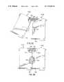
- FIG. 2shows an oblique view of two modules showing structural and electrical features for module connection in accordance with the present invention
- FIG. 3 ashows a front view of the modules shown in FIG. 2 positioned for subsequent engagement with each other, with portions broken away to reveal the connection scheme according to the present invention and associated electronic components;
- FIG. 3 bshows the modules of FIG. 3 a after engagement
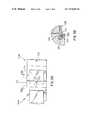
- FIG. 4shows an exploded perspective view of a single module showing the interconnector parts of the present invention enlarged and out-of-scale;
- FIG. 5 ashows a bottom view of a pair of engaged modules in accordance with an embodiment of the present invention
- FIG. 5 bshows a front cut-away view of the modules of FIG. 5 a to reveal a latching and locking scheme in accordance with an embodiment of the present invention
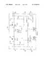
- FIG. 6shows a functional diagram of the power provision features of the interface unit according to the presented invention.
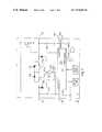
- FIG. 7discloses a functional circuit diagram of the bilateral powering features of a functional unit in accordance with the present invention.
- FIG. 8shows a functional diagram of the unit detection and power features of a modular patient care system in accordance with the present invention.
- FIG. 1discloses a modular patient care system 100 in accordance with the present invention.
- Modular patient care system 100comprises a plurality of modules or units, including interface unit 102 and functional units 104 , detachably coupled to each other to form a linear array. Shown in FIG. 1 are exemplary functional units 104 A, 104 B, 104 C, and 104 D coupled to interface unit 102 . While four functional units are shown in FIG. 1 , a modular patient care system in accordance with the present invention may comprise interface unit 102 coupled to only a single functional unit 104 , or may comprise interface unit 102 coupled to as many as “N” functional units 104 .
- Interface unit 102generally performs the functions of (1) providing a physical attachment of the system to structures such as IV poles and bedrails, (2) providing electrical power to the system, (3) providing an interface between the system and external devices, (4) providing a user interface to the system, and (5) providing overall system control, which includes providing information to and receiving information from functional units 104 .
- Shown in FIG. 1are certain user interface aspects of interface unit 102 , which may include an information display 106 , numerical hardkeys 108 , and softkeys 110 .
- Functional units 104are generally for providing patient therapies or monitoring responsive to information, at least some of which may be received from interface unit 102 . In many cases, functional units 104 are also for communicating information to interface unit 102 .
- functional unit 104 Amay be an infusion pump unit for delivering fluids to a patient responsive to certain commands received from interface unit 102
- functional unit 104 Bmay be a blood pressure monitoring unit for providing patient blood pressure information to the interface unit 102 .
- the scope of the inventionis not so limited, however.
- each functional unitmay have a SELECT key on the face of the unit.
- the systembe designed such that selection of a particular functional unit requires that the SELECT key located on the functional unit be depressed in order to select that functional unit. This requirement will help insure that the proper functional unit is selected, in particular when infusion pump units are used for multiple drug infusions.
- display 106 of interface unit 102is configured so as to act as the user interface for the selected functional unit.
- display 102is configured in accordance with a function specific domain to provide function specific displays and softkeys 110 as explained in greater detail in incorporated U.S. Pat. No. 5,713,856.
- each individual functional unit 104is not critical. Rather, the present invention is directed toward (1) the mechanical and electromechanical coupling of the functional units 104 to each other and to interface unit 102 , and (2) the electrical powering scheme of the modular patient care system 100 .
- functional units 104(1) require means for detachably coupling to each other and to interface unit 102 , and (2) require electrical power.
- interface unit 102 and functional units 104are laterally interchangeable.
- laterally interchangeableit is meant that the modules may be placed in any order in forming a linear array of modules.
- the modular patient care system 100may instead have its modules ordered left-to-right in the sequence 104 C, 102 , 104 B, 104 D, 104 A without affecting its functionality.
- the units 102 and 104 of FIG. 1should have substantially identical interconnection features on their respective left sides, and should have corresponding substantially identical interconnection features on their right sides.
- the interconnection featureswould have substantially identical interconnection features on their respective top sides, and would have corresponding substantially identical interconnection features on their bottom sides. For clarity of explanation, however, only a left-to-right physical arrangement is described.
- each of the units 102 and 104should also have power, unit detection, and communication circuitry which is complementary.
- complementaryit is meant that the units 102 and 104 generally have power, unit detection, and communications circuit contacts on a first side and on a second side, and that the first side contacts of one unit may be connected to corresponding second side contacts of any other unit, with the overall linear array of units comprising modular patient care system 100 being fully operational.
- the first side of a unitis the left side
- the second side of a unitis the right side.
- functional unit 104 Cmust be capable of receiving electrical power from interface unit 102 to its left and transferring it to unit 104 D to its right; yet, if physically interchanged with functional unit 104 B, unit 104 C must be capable of receiving electrical power from interface unit 102 to its right and transferring it to unit 104 A to its left, and so on.
- each functional unit 104may include a unit ID indicator 112 which identifies a logical address of the functional unit within the linear array.
- the logical address of a functional unit 104indicates its position in the linear array relative to other functional units 104 .
- the logical address of a functional unit 104such as unit 104 B, is used by the interface unit 102 to identify and uniquely communicate with functional unit 104 B in a common communications bus environment to be described later.
- the logical address of a functional unitcorresponds to its sequential position in the linear array of functional units.
- 1may illustratively contain functional units 104 A- 104 D with logical addresses A, B, C, and D, ordered left to right.
- the left side of the leftmost unitforms an originating end of the linear array, while the right side of the rightmost unit forms a terminating end of the linear array.
- interface unit 102is substantially identical to interconnection features of functional units 104 . Therefore, only an exemplary unit 104 A will be described. Also, an exemplary unit 104 B, substantially identical to unit 104 A and for connecting thereto, will be described when needed for clarity.
- FIG. 2shows an oblique representation of exemplary units 104 A and 104 B positioned before being matably connected
- FIGS. 3 a and 3 bshow appropriate cut-away views of units 104 A and 104 B during and after the connection process, respectively.
- unit 104 Acomprises a chassis 200 having a left side 202 , a front 204 , and a right side 206 . It is to be appreciated that although FIG. 2 shows numbered components on units 104 A and 104 B according to their visibility in the oblique drawing, the units 104 A and 104 B contain substantially identical numbered components.
- Unit 104 Afurther comprises a male connector portion 208 on right side 206 , a female connector portion 210 on left side 202 , a male elevation feature 212 formed on right side 206 , a female recess feature 214 formed in left side 202 , a catch feature 216 formed near the bottom of right side 206 , and a latch 218 near the bottom of left side 202 .
- Unit 104 Afurther comprises cover 220 tethered to male connector portion 208 for covering the male connector portion 208 during periods of non-use, and pocket 222 formed in right side 206 near male connector portion 208 for receiving cover 220 otherwise.
- Unit 104 Afurther comprises cover 224 tethered to female connector portion 210 for covering female connector portion 210 during periods of non-use, and pocket 226 formed in left side 202 near female connector portion 210 for receiving cover 220 otherwise.
- units 104 A and 104 Bare designed to be connected using the steps of (1) tilting the units relative to each other while inserting male connector portion 208 into female connector portion 210 , (2) swinging down the units to a nearly parallel position such that male elevation feature 212 is received into female recess feature 214 and latch 218 is received into catch feature 216 , and (3) pressing the units together such that latch 218 is locked into catch feature 216 .
- Male connector portion 208 of unit 104 Ais positioned and formed for hingeable connection with female connector portion 210 of unit 104 B for achieving mechanical and electrical coupling of units 104 and 105 .
- male connector portion 208 and female connector portion 210also form a 15-pin electrical connector pair for electrically coupling. This electrical connector pair is for electrically coupling electronic components contained in units 104 A and 104 B, these electronic components being shown generally as elements 300 in FIGS. 3 a and 3 b .
- the geometry of male connector portion 208 and female connector portion 210include lead-in and chamfer to reduce the probability of dropping and off-axis insertion.
- the geometry of the male-female pairis designed to prevent a unit from falling off if it is hooked but not yet latched.
- the mechanical characteristics of the male-female pairare detailed in U.S. patent application Ser. No. 08/403,502, cross-referenced above.
- Male elevation feature 212is formed on right side 206 of unit 104 A for mating with female recess feature 214 formed in left side 202 of unit 104 B to provide multiple contact surfaces for improved front to back stability during vibration of the connected units. Further, the geometry of male elevation feature 212 includes lead-in and chamfer for mechanical guidance into recess feature 214 such that the probability of off-axis insertion is reduced.
- Latch 218is for engaging a catch feature 216 during connection. This keeps the units together mechanically after attachment.
- latch 218is spring loaded with a pre-load force sufficient to positively engage the catch feature 216 , close, and remain latched unless disengaged by an operator.
- techniques known in the artmay be used to shape latch 218 and catch feature 216 such that a small vibration resonates through units 104 A and 104 B upon attachment, to provide tactile feedback to the user.
- Cover 220is for covering male connector portions 208 during transport and periods of non-use.
- cover 220is made of an elastomeric material which is elastic and waterproof.
- Cover 220is tethered to male connector portion 208 to reduce the possibility of being lost or misplaced by the user, and is dimensioned and configured to be swung up and over male hook feature 208 for protection.
- Pocket 222is formed in right side 206 beneath male connector portion 208 for receiving cover 220 , which nests into pocket 224 when not in use. Cover 220 may be swung up out of pocket 222 to cover male connector portion 208 to protect connector portion 208 from dust or fluids. Similar purpose, material, and configurations apply to cover 224 and pocket 226 .
- the covers 220 and 224 and pockets 222 and 226are configured and dimensioned such that the covers recess flush yet are partially compressed when the units 104 A and 104 B are attached, thus providing additional shock cushioning and preventing rattling during vibration or transport.
- the size and geometry of unit 104 Ais generally such that it may be held by a single hand of a user, although the invention is not necessarily so limited. This is generally the same user hand which receives the tactile feedback described above upon unit attachment.
- FIG. 4shows a view of unit 104 A exploded to more succinctly show male connector portion 208 and female connector portion 210 with respect to a preferred embodiment of the invention.
- male connector portion 208comprises electrical contacts 400 contained on a curved lip 404 formed on a body portion 406 .
- female connector portion 210comprises electrical contacts 408 protruding into an aperture 410 formed in body portion 412 .
- the contact geometry and orientation of electrical contacts 400 and 408may allow a first set of individual electrical contact pairs formed by joining the connectors to make electrical connection prior to a second set of electrical contacts during connection. A result of this geometry and orientation will be that the first set of contacts will also break after the second set of contacts during disconnection. This ensures, for example, that an electrical ground connection between the units may made first during module attachment, creating a path to dissipate electrostatic discharge.
- body portions 406 and 412are made of a low surface energy/hydrophobic material to shed fluid from exposed surfaces.
- the electrical contacts 400 and 408are insert-molded into body portions 406 and 412 , which prevents extraneous fluids from accumulating adjacent to electrical connections.
- FIGS. 5A and 5Bshow units 104 A and 104 B with additional features in accordance with a preferred embodiment of the invention.
- FIG. 5Ashows a bottom view of coupled units 104 A and 104 B.
- Unit 104 Bcomprises latch 218 for engaging catch feature 216 of unit 104 A.
- a fastener 500may be employed to provide a means for making the attachment of units 104 A and 104 B permanent until the fastener 500 is released by a user using a releasing technique.
- This releasing techniquemay employ the use of a special tool (not shown) made available only to specified users.
- FIG. 5Bshows a side view of latch 218 engaged to catch feature 216 , further showing a latch tongue 502 of latch 218 which forms a hole 504 in an area which overlaps catch feature 216 .
- Fastener 500which is, for example, a screw, is inserted from the bottom of functional unit 104 A near catch feature 216 through hole 504 and into a boss 506 contained in functional unit 104 A near catch feature 216 .
- the configuration shownadvantageously provides for permanent attachment of the units until a user such as a medical technician disengages fastener 500 . In this manner, for example, miscellaneous persons around and in the area of the modular patient care system 100 are prevented either from intentionally or accidentally causing disconnection of units.
- the unique combination of the module elements describedthus far provide for many advantages in stability, safety, security, and ease of use.
- the attachment of a functional unitmay be achieved in a one hand, single step operation, while the presence of latch 218 and catch feature 216 dictate that detachment must take place in a two step operation.
- Thisis advantageous in a medical environment where quick, easy attachment of units to the linear array may be necessary, but where detachment of units should be permissible only upon an explicit, reasoned desire of a user and not by accident.
- This featureis enhanced an a preferred embodiment of the invention employing a fastener 500 , wherein further steps are needed to detach modules.
- latch 218 and catch feature 216provide for tactile feedback during the attachment operation. This is advantageous in the medical environment by freeing up the eyes of the user during attachment to pay attention to more sensitive events taking place, such as insuring that needles, lines, fluids, or pumps are not being disturbed during the mechanical movement. Further, the avoidance of the need for visual feedback to the user may save precious moments during medical emergencies when the user's eyes are more advantageously averted to the emergency at hand.
- male elevation feature 212 mated to recess feature 214provides for additional front to back stability of the units during handling and abuse. These features also provide guidance during connection to prevent off-axis insertion. Vibration of coupled units is further reduced by the compression of covers 220 and 224 against each other and pockets 222 and 226 .
- the contact geometry, contact orientation, and hook geometry as shown in FIG. 4prevent fluid from accumulating on surfaces of the male connector portion 208 .
- the contact geometry, contact orientation, and contact location of the electrical contacts 408prevent fluid from accumulating on surfaces of the female connector portion 210 .
- Use of low surface energy/hydrophobic material for body portions 406 and 412 , insert-molding of the contacts 400 and 408 , and the presence of covers 220 and 224further discourage unwanted fluid accumulation and ingress.
- electrical poweris supplied to functional modules 104 by interface unit 102 .
- the interface unit 102may be powered by conventional methods known in the art.
- At least one electrical power pathexists among the electrical contacts 408 and 400 at the connecting point of any two units.
- interface unit 102is to supply electrical power to all functional units 104 by powering functional units 104 B and 104 C, which each use a portion of this power and which, in turn, transfer at least a portion of this power further down the line to units 104 A and 104 D, respectively.
- the module powering system in accordance with the present inventionis to permit lateral interchangeability of the modules, and thus the powering system of any functional unit 104 is to be bilateral.
- bilateralit is meant that the functional unit 104 may receive power from either its first or second side, and may transmit this power, if necessary, to attached units on its second or first side, respectively.
- a module powering systemis to comprise an interface unit 102 and functional units 104 which, if they are positioned on the originating or terminating end of a linear array, do not allow a live voltage to exist at the open electrical contacts which will exist at these ends. Such a requirement provides, for example, for added security of the unit from power failure due to accidental or intentional shorting of the exposed power leads.
- FIG. 6shows a functional diagram of the power aspects of interface unit 102 designed in accordance with the present invention.
- Interface unit 102comprises a microprocessor 600 , a power source 602 , a left transistor 604 , and a right transistor 606 .
- Power source 602is adapted for providing an 8-volt DC voltage by either generating its own power, as from a DC voltage source such as an internal battery, or for adapting power from an external AC or DC source, as is known in the art.
- Interface unit 102further comprises left and right power leads 610 and 612 , respectively, for coupling to and providing power to left and right adjacent functional units, respectively, when connected. Power leads 610 and/or 612 will be left open, however, when adjacent units are not connected. Interface unit 102 further comprises left and right module detect leads 614 and 616 , respectively, for detecting the presence of attached functional units on the left and right sides, respectively. Interface unit 102 further comprises ground leads 618 to 620 for providing left and right sense signals, respectively (which in this embodiment are ground signals) to adjacently attached units. It is noted that additional electrical contacts not shown may provide an overall ground plane signal to attached functional units, as is known in the art.
- lead 607 of power source 602is coupled to the source of left transistor 604 and also to the source of right transistor 606 .
- transistors 604 and 606are, in this embodiment, P-channel enhancement MOSFETS.
- the gate of left transistor 604is coupled to left module detect lead 614
- the gate of right transistor 606is coupled to right module detect lead 616 .
- the drain of left transistor 604is coupled to left power lead 610
- the drain of right transistor 606is coupled to right power lead 612 .
- transistor 604will conduct (i.e., create a “short” between its drain and source) when its gate is low with respect to the source, and will not conduct (i.e., create an “open”) when its gate is high.
- Transistor 606behaves similarly.
- left module detect lead 614is grounded by attachment to an external signal, such as a signal provided by an attached functional unit to the left, transistor 604 will conduct, and thus power lead 610 will be coupled to power source lead 607 to provide power.
- transistor 604does not conduct and leaves power lead 610 electrically isolated from power source lead 607 . This, of course, is a desired result. Similar characteristics exist for right module detect lead 616 , transistor 606 , and right power lead 612 .
- FIG. 7shows a functional diagram of the power aspects of an exemplary functional unit 104 A designed in accordance with the present invention.
- Functional unit 104 Acomprises a microprocessor 700 and a load 702 such as an infusion pump motor. It is noted that load 702 may represent any kind of electrical system requiring power, however.
- Functional unit 104 Afurther comprises a left transistor 704 and a right transistor 706 .
- Load 702receives electrical power provided between an input node 707 and a ground plane, generally denoted by element 708 in FIG. 7 .
- Functional unit 104 Afurther comprises a left power lead 710 , a right power lead 712 , a left module detect lead 714 , a right module detect lead 716 , a left ground lead 718 , and a right ground lead 720 .
- the drain of left transistor 704is coupled to the drain of right transistor 706 .
- Transistors 704 and 706are, in this embodiment, P-channel enhancement MOSFETS.
- the source of left transistor 704is coupled to left power lead 710
- the source of right transistor 706is coupled to right power lead 712 .
- Left power lead 710is also coupled through a resistor 722 to the left module detect lead 714 , which is in turn coupled directly to the gate of right transistor 706 .
- right power lead 712is coupled through a resistor 724 to the right module detect lead 716 , which is in turn coupled directly to the gate of left transistor 704 .
- Left power lead 710is coupled to the cathode of a diode 726 whose anode is in turn coupled to input node 707 of load 702 .
- right power lead 712is coupled to the cathode of a diode 728 whose anode is in turn coupled to the input node 707 of load 702 .
- a positive power voltageis present at lead 710
- poweris supplied to load 702 without being supplied to lead 712 unless both transistors 704 and 706 are conductive.
- a positive power voltageis present at lead 712
- poweris supplied to load 702 without being supplied to lead 710 unless both transistors 704 and 706 are conductive.
- transistor 704will conduct (i.e., create a “short” between its drain and source) when its gate is low with respect to the source, and will not conduct (i.e., create an “open”) when its gate is high.
- Transistor 706behaves similarly.
- the gate of transistor 704will be forced low when right module detect lead 716 is grounded by an adjacent attached unit to the right.
- the gate of transistor 706will be forced low when left detect lead 714 is grounded by an adjacent attached unit to the left.
- Schottky diodes 730 and 732are provided across the drain and source of transistors 704 and 706 , respectively, for protection against reverse voltages, as is known in the art. It is noted that, as described above and as shown in FIG. 7 , module 104 A forms a laterally symmetric powering arrangement.
- a modular patient care system 100comprising the interface unit of FIG. 6 and functional modules according to FIG. 7 advantageously provides for bilateral power sourcing and transfer through the functional modules 104 , while providing electrical isolation of power leads of units at the originating and terminating ends, respectively.
- FIG. 8shows the modules of FIG. 6 and FIG. 7 arranged in an exemplary arrangement comprising functional unit 104 A at the originating (left) end, functional unit 104 D at the terminating (right) end, and units 104 B, 102 , and 104 C in the middle, respectively.
- the electrical leads between unitsare arranged according to the following simple scheme.
- Left power leads ( 610 or 710 )are coupled to right power leads ( 712 or 612 ) in any pair of adjacent units.
- Left module detect leads ( 714 or 614 )are coupled to right ground leads ( 620 or 720 ) in any pair of adjacent units.
- left ground leads ( 618 or 718 )are coupled to right module detect leads ( 716 or 616 ) in any pair of adjacent units.
- the powering configuration of the modular patient care system 100 shown in FIG. 8advantageously functions as follows.
- lead 720 of unit 104 Bgrounds the gate of left transistor 704 of unit 102 via module detect lead 614 .
- Transistor 604is turned on, and power is thus supplied through left power lead 610 of unit 102 to right power lead 712 of unit 104 B, thus powering the load 702 of unit 104 B.
- Left ground lead 618 of unit 102grounds the gate of left transistor 704 of unit 104 B through right module detect lead 716 , making transistor 704 conductive.
- right ground lead 720 of unit 104 Agrounds the gate of right transistor 706 of unit 104 B, making transistor 706 conductive.
- left module detect lead 714 of unit 104 ABecause it is the leftmost unit.
- right transistor 706 of unit 104 Aremains turned off.
- left power lead 710 of leftmost unit 104 Ais electrically isolated from right power lead 712 , which is the desired result.
- right side units 104 C and 104 Doperate in a similar but reflexive fashion to the left side units 104 A and 104 B.
- poweris provided to both units 104 C and 104 D, but right power lead 712 of rightmost unit 104 D remains electrically isolated from a power source. This, of course, is the desired result.
- the units 102 and 104 A through 104 Dcan be arranged in any order in FIG. 8 with the desired result of (1) powering of all units, (2) electrical isolation of the left power leads 710 or 610 of the leftmost (originating) unit, and (3) electrical isolation of the right power leads 712 or 612 of the rightmost (terminating) unit.
Landscapes
- Health & Medical Sciences (AREA)
- Engineering & Computer Science (AREA)
- Biomedical Technology (AREA)
- Public Health (AREA)
- General Health & Medical Sciences (AREA)
- Epidemiology (AREA)
- Business, Economics & Management (AREA)
- Medical Informatics (AREA)
- Primary Health Care (AREA)
- General Business, Economics & Management (AREA)
- Heart & Thoracic Surgery (AREA)
- Vascular Medicine (AREA)
- Anesthesiology (AREA)
- Hematology (AREA)
- Life Sciences & Earth Sciences (AREA)
- Animal Behavior & Ethology (AREA)
- Veterinary Medicine (AREA)
- Chemical & Material Sciences (AREA)
- Bioinformatics & Cheminformatics (AREA)
- Medicinal Chemistry (AREA)
- Infusion, Injection, And Reservoir Apparatuses (AREA)
Abstract
Description
Claims (10)
Priority Applications (9)
| Application Number | Priority Date | Filing Date | Title |
|---|---|---|---|
| US09/379,212US7074205B1 (en) | 1995-03-13 | 1999-08-23 | Method and apparatus for power connection in a modular patient care system |
| US09/793,475US7384410B2 (en) | 1995-03-13 | 2001-02-26 | System and method for managing patient care |
| US11/318,412US8639521B2 (en) | 1995-03-13 | 2005-12-23 | Method for programming a patient care device |
| US11/318,017US20060190302A1 (en) | 1995-03-13 | 2005-12-23 | System and method for managing patient care |
| US11/318,018US7771385B2 (en) | 1995-03-13 | 2005-12-23 | Method of providing care to a patient |
| US11/317,277US7771386B2 (en) | 1995-03-13 | 2005-12-23 | Patient care system |
| US11/317,867US8645154B2 (en) | 1995-03-13 | 2005-12-23 | Method for delivering a fluid to a patient |
| US11/484,319US7553291B2 (en) | 1995-03-13 | 2006-07-10 | Modular patient care system with interchangeable modules |
| US12/854,087US8235938B2 (en) | 1995-03-13 | 2010-08-10 | Method of providing care to a patient |
Applications Claiming Priority (3)
| Application Number | Priority Date | Filing Date | Title |
|---|---|---|---|
| US08/403,503US5713856A (en) | 1995-03-13 | 1995-03-13 | Modular patient care system |
| US08/871,307US5941846A (en) | 1995-03-13 | 1997-06-09 | Method and apparatus for power connection in a modular patient care system |
| US09/379,212US7074205B1 (en) | 1995-03-13 | 1999-08-23 | Method and apparatus for power connection in a modular patient care system |
Related Parent Applications (1)
| Application Number | Title | Priority Date | Filing Date |
|---|---|---|---|
| US08/871,307ContinuationUS5941846A (en) | 1995-03-13 | 1997-06-09 | Method and apparatus for power connection in a modular patient care system |
Related Child Applications (3)
| Application Number | Title | Priority Date | Filing Date |
|---|---|---|---|
| US09/793,475Continuation-In-PartUS7384410B2 (en) | 1995-03-13 | 2001-02-26 | System and method for managing patient care |
| US11/318,018Continuation-In-PartUS7771385B2 (en) | 1995-03-13 | 2005-12-23 | Method of providing care to a patient |
| US11/484,319ContinuationUS7553291B2 (en) | 1995-03-13 | 2006-07-10 | Modular patient care system with interchangeable modules |
Publications (1)
| Publication Number | Publication Date |
|---|---|
| US7074205B1true US7074205B1 (en) | 2006-07-11 |
Family
ID=27409444
Family Applications (3)
| Application Number | Title | Priority Date | Filing Date |
|---|---|---|---|
| US09/379,212Expired - Fee RelatedUS7074205B1 (en) | 1995-03-13 | 1999-08-23 | Method and apparatus for power connection in a modular patient care system |
| US11/484,319Expired - Fee RelatedUS7553291B2 (en) | 1995-03-13 | 2006-07-10 | Modular patient care system with interchangeable modules |
| US12/854,087Expired - Fee RelatedUS8235938B2 (en) | 1995-03-13 | 2010-08-10 | Method of providing care to a patient |
Family Applications After (2)
| Application Number | Title | Priority Date | Filing Date |
|---|---|---|---|
| US11/484,319Expired - Fee RelatedUS7553291B2 (en) | 1995-03-13 | 2006-07-10 | Modular patient care system with interchangeable modules |
| US12/854,087Expired - Fee RelatedUS8235938B2 (en) | 1995-03-13 | 2010-08-10 | Method of providing care to a patient |
Country Status (1)
| Country | Link |
|---|---|
| US (3) | US7074205B1 (en) |
Cited By (44)
| Publication number | Priority date | Publication date | Assignee | Title |
|---|---|---|---|---|
| US7668731B2 (en) | 2002-01-11 | 2010-02-23 | Baxter International Inc. | Medication delivery system |
| US7927313B2 (en) | 2004-05-27 | 2011-04-19 | Baxter International Inc. | Medical device configuration based on recognition of identification information |
| US7934912B2 (en) | 2007-09-27 | 2011-05-03 | Curlin Medical Inc | Peristaltic pump assembly with cassette and mounting pin arrangement |
| US8062008B2 (en) | 2007-09-27 | 2011-11-22 | Curlin Medical Inc. | Peristaltic pump and removable cassette therefor |
| US8083503B2 (en) | 2007-09-27 | 2011-12-27 | Curlin Medical Inc. | Peristaltic pump assembly and regulator therefor |
| US8315885B2 (en) | 2009-04-14 | 2012-11-20 | Baxter International Inc. | Therapy management development platform |
| US8945066B2 (en) | 2009-11-06 | 2015-02-03 | Crisi Medical Systems, Inc. | Medication injection site and data collection system |
| US9078809B2 (en) | 2011-06-16 | 2015-07-14 | Crisi Medical Systems, Inc. | Medication dose preparation and transfer system |
| US9101534B2 (en) | 2010-04-27 | 2015-08-11 | Crisi Medical Systems, Inc. | Medication and identification information transfer apparatus |
| US9514131B1 (en) | 2010-05-30 | 2016-12-06 | Crisi Medical Systems, Inc. | Medication container encoding, verification, and identification |
| US9744298B2 (en) | 2011-06-22 | 2017-08-29 | Crisi Medical Systems, Inc. | Selectively controlling fluid flow through a fluid pathway |
| US9934540B2 (en) | 2011-07-01 | 2018-04-03 | Baxter International Inc. | Systems and methods for intelligent patient interface device |
| US9931498B2 (en) | 2013-03-13 | 2018-04-03 | Crisi Medical Systems, Inc. | Injection site information cap |
| US10293107B2 (en) | 2011-06-22 | 2019-05-21 | Crisi Medical Systems, Inc. | Selectively Controlling fluid flow through a fluid pathway |
| US20190251310A1 (en)* | 2018-02-12 | 2019-08-15 | Hand Held Products, Inc. | Apparatuses and systems for attaching modules on a mobile scanning device |
| US10405757B2 (en) | 2014-02-25 | 2019-09-10 | Icu Medical, Inc. | Patient monitoring system with gatekeeper signal |
| US10492991B2 (en) | 2010-05-30 | 2019-12-03 | Crisi Medical Systems, Inc. | Medication container encoding, verification, and identification |
| CN113490462A (en)* | 2019-02-26 | 2021-10-08 | 康曼德公司 | Modular docking system for electrosurgical devices |
| US11219578B2 (en) | 2015-06-19 | 2022-01-11 | Takeda Pharmaceutical Company Limited | Pooling device for single or multiple medical containers |
| US11270792B2 (en) | 2015-10-19 | 2022-03-08 | Icu Medical, Inc. | Hemodynamic monitoring system with detachable display unit |
| US11471206B2 (en) | 2018-09-07 | 2022-10-18 | Cilag Gmbh International | Method for controlling a modular energy system user interface |
| US11515667B2 (en)* | 2020-01-21 | 2022-11-29 | Carefusion 303, Inc. | Method and system for modular connections with electrical components |
| US11696789B2 (en) | 2018-09-07 | 2023-07-11 | Cilag Gmbh International | Consolidated user interface for modular energy system |
| US11743665B2 (en) | 2019-03-29 | 2023-08-29 | Cilag Gmbh International | Modular surgical energy system with module positional awareness sensing with time counter |
| US11804679B2 (en) | 2018-09-07 | 2023-10-31 | Cilag Gmbh International | Flexible hand-switch circuit |
| US11857252B2 (en) | 2021-03-30 | 2024-01-02 | Cilag Gmbh International | Bezel with light blocking features for modular energy system |
| US11903900B2 (en) | 2018-10-03 | 2024-02-20 | Takeda Pharmaceutical Company Limited | Packaging for multiple containers |
| US11923084B2 (en) | 2018-09-07 | 2024-03-05 | Cilag Gmbh International | First and second communication protocol arrangement for driving primary and secondary devices through a single port |
| US11950860B2 (en) | 2021-03-30 | 2024-04-09 | Cilag Gmbh International | User interface mitigation techniques for modular energy systems |
| US11968776B2 (en) | 2021-03-30 | 2024-04-23 | Cilag Gmbh International | Method for mechanical packaging for modular energy system |
| US11963727B2 (en) | 2021-03-30 | 2024-04-23 | Cilag Gmbh International | Method for system architecture for modular energy system |
| USD1026010S1 (en) | 2019-09-05 | 2024-05-07 | Cilag Gmbh International | Energy module with alert screen with graphical user interface |
| US11978554B2 (en) | 2021-03-30 | 2024-05-07 | Cilag Gmbh International | Radio frequency identification token for wireless surgical instruments |
| US11980411B2 (en) | 2021-03-30 | 2024-05-14 | Cilag Gmbh International | Header for modular energy system |
| US12004824B2 (en) | 2021-03-30 | 2024-06-11 | Cilag Gmbh International | Architecture for modular energy system |
| US12040749B2 (en) | 2021-03-30 | 2024-07-16 | Cilag Gmbh International | Modular energy system with dual amplifiers and techniques for updating parameters thereof |
| US12079460B2 (en) | 2022-06-28 | 2024-09-03 | Cilag Gmbh International | Profiles for modular energy system |
| US12144136B2 (en) | 2018-09-07 | 2024-11-12 | Cilag Gmbh International | Modular surgical energy system with module positional awareness with digital logic |
| US12214161B2 (en) | 2018-10-03 | 2025-02-04 | Takeda Pharmaceutical Company Limited | Pooling device for single or multiple medical containers |
| US12228987B2 (en) | 2021-03-30 | 2025-02-18 | Cilag Gmbh International | Method for energy delivery for modular energy system |
| US12235697B2 (en) | 2021-03-30 | 2025-02-25 | Cilag Gmbh International | Backplane connector attachment mechanism for modular energy system |
| US12293432B2 (en) | 2021-04-14 | 2025-05-06 | Cilag Gmbh International | Cooperative overlays of interacting instruments which result in both overlays being effected |
| US12369994B2 (en) | 2021-03-30 | 2025-07-29 | Cilag Gmbh International | Modular energy system with multi-energy port splitter for multiple energy devices |
| US12444094B2 (en) | 2022-03-07 | 2025-10-14 | Cilag Gmbh International | Systems and methods for controlling surgical data overlay |
Families Citing this family (94)
| Publication number | Priority date | Publication date | Assignee | Title |
|---|---|---|---|---|
| BRPI0418857A (en)* | 2004-05-14 | 2007-11-20 | Nokia Corp | computer program method, system and product for controlling at least one device function |
| US7751907B2 (en) | 2007-05-24 | 2010-07-06 | Smiths Medical Asd, Inc. | Expert system for insulin pump therapy |
| US9026370B2 (en) | 2007-12-18 | 2015-05-05 | Hospira, Inc. | User interface improvements for medical devices |
| US8076618B2 (en)* | 2008-09-10 | 2011-12-13 | Enthermics Medical Systems, Inc. | Modular fluid warmer |
| US20100069939A1 (en)* | 2008-09-15 | 2010-03-18 | Olympus Medical Systems Corp. | Operation system |
| US8271106B2 (en) | 2009-04-17 | 2012-09-18 | Hospira, Inc. | System and method for configuring a rule set for medical event management and responses |
| EP2724739B1 (en) | 2009-07-30 | 2015-07-01 | Tandem Diabetes Care, Inc. | Portable infusion pump system |
| US11244745B2 (en) | 2010-01-22 | 2022-02-08 | Deka Products Limited Partnership | Computer-implemented method, system, and apparatus for electronic patient care |
| US20110313789A1 (en) | 2010-01-22 | 2011-12-22 | Deka Products Limited Partnership | Electronic patient monitoring system |
| US11210611B2 (en) | 2011-12-21 | 2021-12-28 | Deka Products Limited Partnership | System, method, and apparatus for electronic patient care |
| US10242159B2 (en) | 2010-01-22 | 2019-03-26 | Deka Products Limited Partnership | System and apparatus for electronic patient care |
| US9789247B2 (en) | 2011-12-21 | 2017-10-17 | Deka Products Limited Partnership | Syringe pump, and related method and system |
| US9744300B2 (en) | 2011-12-21 | 2017-08-29 | Deka Products Limited Partnership | Syringe pump and related method |
| US11881307B2 (en) | 2012-05-24 | 2024-01-23 | Deka Products Limited Partnership | System, method, and apparatus for electronic patient care |
| US10911515B2 (en) | 2012-05-24 | 2021-02-02 | Deka Products Limited Partnership | System, method, and apparatus for electronic patient care |
| US11164672B2 (en) | 2010-01-22 | 2021-11-02 | Deka Products Limited Partnership | System and apparatus for electronic patient care |
| US9677555B2 (en) | 2011-12-21 | 2017-06-13 | Deka Products Limited Partnership | System, method, and apparatus for infusing fluid |
| US10453157B2 (en) | 2010-01-22 | 2019-10-22 | Deka Products Limited Partnership | System, method, and apparatus for electronic patient care |
| US9295778B2 (en) | 2011-12-21 | 2016-03-29 | Deka Products Limited Partnership | Syringe pump |
| US20120184882A1 (en)* | 2010-11-12 | 2012-07-19 | Zoll Medical Corporation | Hand Mounted CPR Chest Compression Monitor |
| AU2012299169B2 (en) | 2011-08-19 | 2017-08-24 | Icu Medical, Inc. | Systems and methods for a graphical interface including a graphical representation of medical data |
| CA2852271A1 (en) | 2011-10-21 | 2013-04-25 | Hospira, Inc. | Medical device update system |
| US10022498B2 (en) | 2011-12-16 | 2018-07-17 | Icu Medical, Inc. | System for monitoring and delivering medication to a patient and method of using the same to minimize the risks associated with automated therapy |
| US9675756B2 (en) | 2011-12-21 | 2017-06-13 | Deka Products Limited Partnership | Apparatus for infusing fluid |
| US10563681B2 (en) | 2011-12-21 | 2020-02-18 | Deka Products Limited Partnership | System, method, and apparatus for clamping |
| US10722645B2 (en) | 2011-12-21 | 2020-07-28 | Deka Products Limited Partnership | Syringe pump, and related method and system |
| US11295846B2 (en) | 2011-12-21 | 2022-04-05 | Deka Products Limited Partnership | System, method, and apparatus for infusing fluid |
| US12196364B2 (en) | 2011-12-21 | 2025-01-14 | DEKA Research Products Limited Partnership | System, method, and apparatus for clamping |
| US11217340B2 (en) | 2011-12-21 | 2022-01-04 | Deka Products Limited Partnership | Syringe pump having a pressure sensor assembly |
| US12131826B2 (en) | 2011-12-21 | 2024-10-29 | Deka Products Limited Partnership | Syringe pump and related method |
| US8636202B2 (en)* | 2012-01-25 | 2014-01-28 | Codonics, Inc. | First time confirmation of database entry |
| JP6306566B2 (en) | 2012-03-30 | 2018-04-04 | アイシーユー・メディカル・インコーポレーテッド | Air detection system and method for detecting air in an infusion system pump |
| US9180242B2 (en) | 2012-05-17 | 2015-11-10 | Tandem Diabetes Care, Inc. | Methods and devices for multiple fluid transfer |
| US9381297B2 (en) | 2012-06-07 | 2016-07-05 | Tandem Diabetes Care, Inc. | Sealed infusion device with electrical connector port |
| AU2013296555B2 (en) | 2012-07-31 | 2017-10-19 | Icu Medical, Inc. | Patient care system for critical medications |
| JP6105607B2 (en)* | 2012-09-27 | 2017-03-29 | テルモ株式会社 | Device mounting apparatus and method for controlling device mounting apparatus |
| ES2878067T3 (en)* | 2013-01-23 | 2021-11-18 | Baxter Corp Englewood | Patient care device specific configuration output |
| WO2014138446A1 (en) | 2013-03-06 | 2014-09-12 | Hospira,Inc. | Medical device communication method |
| US9522224B2 (en) | 2013-03-14 | 2016-12-20 | Carefusion 303, Inc. | Inductively powered modular medical device system |
| US9968739B2 (en) | 2013-03-14 | 2018-05-15 | Carefusion 303, Inc. | Rotary valve for a disposable infusion set |
| US9173998B2 (en) | 2013-03-14 | 2015-11-03 | Tandem Diabetes Care, Inc. | System and method for detecting occlusions in an infusion pump |
| US9468714B2 (en) | 2013-03-14 | 2016-10-18 | Carefusion 303, Inc. | Memory and identification associated with IV set |
| US10226571B2 (en) | 2013-03-14 | 2019-03-12 | Carefusion 303, Inc. | Pump segment placement |
| US9492608B2 (en) | 2013-03-15 | 2016-11-15 | Tandem Diabetes Care, Inc. | Method and device utilizing insulin delivery protocols |
| US10039878B2 (en) | 2013-05-07 | 2018-08-07 | Carefusion 303, Inc. | Method for reliable intermodule connection in an infusion system |
| AU2014268355B2 (en) | 2013-05-24 | 2018-06-14 | Icu Medical, Inc. | Multi-sensor infusion system for detecting air or an occlusion in the infusion system |
| US10166328B2 (en) | 2013-05-29 | 2019-01-01 | Icu Medical, Inc. | Infusion system which utilizes one or more sensors and additional information to make an air determination regarding the infusion system |
| WO2014194065A1 (en) | 2013-05-29 | 2014-12-04 | Hospira, Inc. | Infusion system and method of use which prevents over-saturation of an analog-to-digital converter |
| EP3039596A4 (en) | 2013-08-30 | 2017-04-12 | Hospira, Inc. | System and method of monitoring and managing a remote infusion regimen |
| US9662436B2 (en) | 2013-09-20 | 2017-05-30 | Icu Medical, Inc. | Fail-safe drug infusion therapy system |
| EP4250313A3 (en) | 2013-12-26 | 2023-11-22 | Tandem Diabetes Care, Inc. | Integration of infusion pump with remote electronic device |
| US9545475B2 (en) | 2014-02-07 | 2017-01-17 | Carefusion 303, Inc. | Adjustment of infusion user interface upon docking event |
| WO2015127189A1 (en) | 2014-02-21 | 2015-08-27 | Deka Products Limited Partnership | Syringe pump having a pressure sensor assembly |
| EP3110474B1 (en) | 2014-02-28 | 2019-12-18 | ICU Medical, Inc. | Infusion system and method which utilizes dual wavelength optical air-in-line detection |
| EP3138032B1 (en) | 2014-04-30 | 2024-07-24 | ICU Medical, Inc. | Patient care system with conditional alarm forwarding |
| US11344673B2 (en) | 2014-05-29 | 2022-05-31 | Icu Medical, Inc. | Infusion system and pump with configurable closed loop delivery rate catch-up |
| US9724470B2 (en) | 2014-06-16 | 2017-08-08 | Icu Medical, Inc. | System for monitoring and delivering medication to a patient and method of using the same to minimize the risks associated with automated therapy |
| JP6707545B2 (en)* | 2014-09-15 | 2020-06-10 | カプセル・テック・インコーポレイテッド | Capture and manage health management information |
| US9539383B2 (en) | 2014-09-15 | 2017-01-10 | Hospira, Inc. | System and method that matches delayed infusion auto-programs with manually entered infusion programs and analyzes differences therein |
| EP3193975B1 (en) | 2014-09-18 | 2022-07-06 | DEKA Products Limited Partnership | Apparatus and method for infusing fluid through a tube by appropriately heating the tube |
| BR112017006984B1 (en) | 2014-10-10 | 2022-10-11 | Becton, Dickinson And Company | VOLTAGE CONTROL DEVICE AND LABELING SYSTEM |
| WO2016057751A1 (en) | 2014-10-10 | 2016-04-14 | Becton, Dickinson And Company | Syringe labeling device |
| CN107533578B (en)* | 2014-12-18 | 2021-04-02 | 德尔格制造股份两合公司 | Smart Patient Monitor Base |
| US11344668B2 (en)* | 2014-12-19 | 2022-05-31 | Icu Medical, Inc. | Infusion system with concurrent TPN/insulin infusion |
| US10850024B2 (en) | 2015-03-02 | 2020-12-01 | Icu Medical, Inc. | Infusion system, device, and method having advanced infusion features |
| WO2016178973A1 (en)* | 2015-05-01 | 2016-11-10 | Laboratory Corporation Of America Holdings | Enhanced decision support for systems, methods, and media for laboratory benefit services |
| US11324886B2 (en) | 2015-06-12 | 2022-05-10 | Carefusion 303, Inc. | Medical device with automated modality switching |
| EP3352657B1 (en) | 2015-09-23 | 2024-02-14 | Koninklijke Philips N.V. | Modular pulse oximeter platform with interchangeable modules |
| WO2017060260A1 (en)* | 2015-10-09 | 2017-04-13 | Fresenius Vial Sas | Rack module and rack |
| KR102711298B1 (en) | 2015-10-13 | 2024-09-30 | 벡톤 디킨슨 앤드 컴퍼니 | Multi-modal fluorescence imaging flow cytometry system |
| CA3023658C (en) | 2016-05-13 | 2023-03-07 | Icu Medical, Inc. | Infusion pump system and method with common line auto flush |
| WO2017214441A1 (en) | 2016-06-10 | 2017-12-14 | Icu Medical, Inc. | Acoustic flow sensor for continuous medication flow measurements and feedback control of infusion |
| EP3425765A1 (en) | 2017-07-03 | 2019-01-09 | France Brevets | Adaptor for a device to bus contact connection |
| CA3069538A1 (en) | 2017-07-19 | 2019-01-24 | Smiths Medical Asd, Inc. | Housing arrangements for infusion pumps |
| US10607051B2 (en)* | 2017-11-10 | 2020-03-31 | Orange Electronic Co., Ltd | Method for setting tire pressure measurement device |
| US10089055B1 (en) | 2017-12-27 | 2018-10-02 | Icu Medical, Inc. | Synchronized display of screen content on networked devices |
| WO2019232080A1 (en)* | 2018-05-31 | 2019-12-05 | Tc1 Llc | Improved blood pump controllers |
| CA3106519A1 (en) | 2018-07-17 | 2020-01-23 | Icu Medical, Inc. | Systems and methods for facilitating clinical messaging in a network environment |
| ES2985889T3 (en) | 2018-07-17 | 2024-11-07 | Icu Medical Inc | Updating infusion pump drug libraries and operational software in a networked environment |
| JP7047185B2 (en) | 2018-08-16 | 2022-04-04 | デカ・プロダクツ・リミテッド・パートナーシップ | Medical pump |
| DE102018122994A1 (en)* | 2018-09-19 | 2020-03-19 | B. Braun Melsungen Ag | Lock for a modular organization system |
| CA3138528A1 (en) | 2019-05-08 | 2020-11-12 | Icu Medical, Inc. | Threshold signature based medical device management |
| US11278671B2 (en) | 2019-12-04 | 2022-03-22 | Icu Medical, Inc. | Infusion pump with safety sequence keypad |
| US11590057B2 (en) | 2020-04-03 | 2023-02-28 | Icu Medical, Inc. | Systems, methods, and components for transferring medical fluids |
| EP4175621A4 (en)* | 2020-07-02 | 2024-07-17 | ICU Medical, Inc. | GEODEPENDENT RECONFIGURATION OF INFUSION PUMP SETTINGS |
| CA3189781A1 (en) | 2020-07-21 | 2022-01-27 | Icu Medical, Inc. | Fluid transfer devices and methods of use |
| EP4208798A4 (en) | 2020-09-05 | 2024-10-09 | ICU Medical, Inc. | Identity-based secure medical device communications |
| US11135360B1 (en) | 2020-12-07 | 2021-10-05 | Icu Medical, Inc. | Concurrent infusion with common line auto flush |
| USD1091564S1 (en) | 2021-10-13 | 2025-09-02 | Icu Medical, Inc. | Display screen or portion thereof with graphical user interface for a medical device |
| DE102021127476A1 (en)* | 2021-10-22 | 2023-04-27 | B. Braun Melsungen Aktiengesellschaft | System and method for delivering medication to a medical device |
| CA3241894A1 (en) | 2021-12-10 | 2023-06-15 | Icu Medical, Inc. | Medical fluid compounding systems with coordinated flow control |
| AU2022483600A1 (en)* | 2022-10-28 | 2025-05-15 | Carefusion 303, Inc. | Modular infusion control device and method |
| EP4574186A1 (en)* | 2023-12-20 | 2025-06-25 | CareFusion 303, Inc. | Infusion module adapter |
| US20250229021A1 (en)* | 2024-01-16 | 2025-07-17 | Craig Anthony Lampe | Intuitive Total Intravenous Anesthesia Infusion System and Method of Operation |
Citations (27)
| Publication number | Priority date | Publication date | Assignee | Title |
|---|---|---|---|---|
| US4529401A (en) | 1982-01-11 | 1985-07-16 | Cardiac Pacemakers, Inc. | Ambulatory infusion pump having programmable parameters |
| US4756706A (en) | 1985-01-23 | 1988-07-12 | American Hospital Supply Corporation | Centrally managed modular infusion pump system |
| US4785969A (en) | 1986-11-10 | 1988-11-22 | Pyxis Corporation | Medication dispensing system |
| US4847764A (en) | 1987-05-21 | 1989-07-11 | Meditrol, Inc. | System for dispensing drugs in health care institutions |
| US4857713A (en) | 1986-02-14 | 1989-08-15 | Brown Jack D | Hospital error avoidance system |
| US4898578A (en) | 1988-01-26 | 1990-02-06 | Baxter International Inc. | Drug infusion system with calculator |
| US5038800A (en) | 1989-03-03 | 1991-08-13 | Fukuda Denshi Co., Ltd. | System for monitoring patient by using LAN |
| US5041086A (en) | 1987-12-04 | 1991-08-20 | Pacesetter Infusion, Ltd. | Clinical configuration of multimode medication infusion system |
| US5047948A (en) | 1989-04-25 | 1991-09-10 | Turner Joseph D | Medication dispensing system |
| US5153827A (en) | 1989-01-30 | 1992-10-06 | Omni-Flow, Inc. | An infusion management and pumping system having an alarm handling system |
| US5181910A (en) | 1991-02-28 | 1993-01-26 | Pharmacia Deltec, Inc. | Method and apparatus for a fluid infusion system with linearized flow rate change |
| US5301105A (en) | 1991-04-08 | 1994-04-05 | Desmond D. Cummings | All care health management system |
| US5527289A (en) | 1992-04-15 | 1996-06-18 | Hill-Rom Company, Inc. | IV management apparatus |
| US5573506A (en) | 1994-11-25 | 1996-11-12 | Block Medical, Inc. | Remotely programmable infusion system |
| US5640953A (en) | 1995-03-09 | 1997-06-24 | Siemens Medical Systems, Inc. | Portable patient monitor reconfiguration system |
| US5713856A (en) | 1995-03-13 | 1998-02-03 | Alaris Medical Systems, Inc. | Modular patient care system |
| US5732401A (en) | 1996-03-29 | 1998-03-24 | Intellitecs International Ltd. | Activity based cost tracking systems |
| US5781442A (en) | 1995-05-15 | 1998-07-14 | Alaris Medical Systems, Inc. | System and method for collecting data and managing patient care |
| US5885245A (en) | 1996-08-02 | 1999-03-23 | Sabratek Corporation | Medical apparatus with remote virtual input device |
| US5890129A (en) | 1997-05-30 | 1999-03-30 | Spurgeon; Loren J. | System for exchanging health care insurance information |
| US5895371A (en) | 1996-08-27 | 1999-04-20 | Sabratek Corporation | Medical treatment apparatus and method |
| US5924074A (en) | 1996-09-27 | 1999-07-13 | Azron Incorporated | Electronic medical records system |
| US5941846A (en) | 1995-03-13 | 1999-08-24 | Alaris Medical Systems, Inc. | Method and apparatus for power connection in a modular patient care system |
| US5963565A (en) | 1996-10-31 | 1999-10-05 | Altera Corporation | Apparatus and method for external supervision of electronic test equipment operating parameters |
| US6055458A (en) | 1997-08-28 | 2000-04-25 | Bausch & Lomb Surgical, Inc. | Modes/surgical functions |
| JP2000189514A (en) | 1998-06-16 | 2000-07-11 | Sarcos Inc | Automatic management device for multiple drug administration |
| US20020026330A1 (en) | 2000-08-23 | 2002-02-28 | Klein Edward E. | System and method for patient medication management and compliance using a portable computing device |
Family Cites Families (12)
| Publication number | Priority date | Publication date | Assignee | Title |
|---|---|---|---|---|
| US5935099A (en) | 1992-09-09 | 1999-08-10 | Sims Deltec, Inc. | Drug pump systems and methods |
| US4835372A (en) | 1985-07-19 | 1989-05-30 | Clincom Incorporated | Patient care system |
| EP0497041B1 (en) | 1991-01-31 | 1997-01-08 | Baxter International Inc. | Automated infusion pump with replaceable memory cartridges |
| WO1993024893A1 (en) | 1992-05-26 | 1993-12-09 | Baxter International Inc. | Infusion pump configuration scheme using eeproms |
| JP3660678B2 (en) | 1992-10-15 | 2005-06-15 | ザ ゼネラル ホスピタル コーポレーション | Infusion pump with electronically loadable drug library |
| WO1994016617A1 (en) | 1993-01-22 | 1994-08-04 | Minnesota Mining And Manufacturing Company | Electrical safety system for electrical device |
| US5434775A (en)* | 1993-11-04 | 1995-07-18 | The General Hospital Corporation | Managing an inventory of devices |
| US5685844A (en) | 1995-01-06 | 1997-11-11 | Abbott Laboratories | Medicinal fluid pump having multiple stored protocols |
| US5782805A (en) | 1996-04-10 | 1998-07-21 | Meinzer; Randolph | Medical infusion pump |
| AU9104498A (en) | 1997-08-22 | 1999-03-16 | Deka Products Limited Partnership | System and method for intelligent admixture and delivery of medications |
| US5935088A (en)* | 1997-09-08 | 1999-08-10 | Bosley; Marguerite | Massaging apparatus with vacuum, auxiliary power source and pinch rollers |
| WO1999032031A1 (en) | 1997-12-22 | 1999-07-01 | Siemens Medical Systems, Inc. | Automatic configuration of medical equipment |
- 1999
- 1999-08-23USUS09/379,212patent/US7074205B1/ennot_activeExpired - Fee Related
- 2006
- 2006-07-10USUS11/484,319patent/US7553291B2/ennot_activeExpired - Fee Related
- 2010
- 2010-08-10USUS12/854,087patent/US8235938B2/ennot_activeExpired - Fee Related
Patent Citations (30)
| Publication number | Priority date | Publication date | Assignee | Title |
|---|---|---|---|---|
| US4529401A (en) | 1982-01-11 | 1985-07-16 | Cardiac Pacemakers, Inc. | Ambulatory infusion pump having programmable parameters |
| US4756706A (en) | 1985-01-23 | 1988-07-12 | American Hospital Supply Corporation | Centrally managed modular infusion pump system |
| US4857713A (en) | 1986-02-14 | 1989-08-15 | Brown Jack D | Hospital error avoidance system |
| US4785969A (en) | 1986-11-10 | 1988-11-22 | Pyxis Corporation | Medication dispensing system |
| US4847764C1 (en) | 1987-05-21 | 2001-09-11 | Meditrol Inc | System for dispensing drugs in health care instituions |
| US4847764A (en) | 1987-05-21 | 1989-07-11 | Meditrol, Inc. | System for dispensing drugs in health care institutions |
| US5041086A (en) | 1987-12-04 | 1991-08-20 | Pacesetter Infusion, Ltd. | Clinical configuration of multimode medication infusion system |
| US4898578A (en) | 1988-01-26 | 1990-02-06 | Baxter International Inc. | Drug infusion system with calculator |
| US5153827A (en) | 1989-01-30 | 1992-10-06 | Omni-Flow, Inc. | An infusion management and pumping system having an alarm handling system |
| US5317506A (en) | 1989-01-30 | 1994-05-31 | Abbott Laboratories | Infusion fluid management system |
| US5038800A (en) | 1989-03-03 | 1991-08-13 | Fukuda Denshi Co., Ltd. | System for monitoring patient by using LAN |
| US5047948A (en) | 1989-04-25 | 1991-09-10 | Turner Joseph D | Medication dispensing system |
| US5181910A (en) | 1991-02-28 | 1993-01-26 | Pharmacia Deltec, Inc. | Method and apparatus for a fluid infusion system with linearized flow rate change |
| US5301105A (en) | 1991-04-08 | 1994-04-05 | Desmond D. Cummings | All care health management system |
| US5527289A (en) | 1992-04-15 | 1996-06-18 | Hill-Rom Company, Inc. | IV management apparatus |
| US5573506A (en) | 1994-11-25 | 1996-11-12 | Block Medical, Inc. | Remotely programmable infusion system |
| US5871465A (en) | 1994-11-25 | 1999-02-16 | I-Flow Corporation | Remotely programmable infusion system |
| US5640953A (en) | 1995-03-09 | 1997-06-24 | Siemens Medical Systems, Inc. | Portable patient monitor reconfiguration system |
| US5941846A (en) | 1995-03-13 | 1999-08-24 | Alaris Medical Systems, Inc. | Method and apparatus for power connection in a modular patient care system |
| US5713856A (en) | 1995-03-13 | 1998-02-03 | Alaris Medical Systems, Inc. | Modular patient care system |
| US5781442A (en) | 1995-05-15 | 1998-07-14 | Alaris Medical Systems, Inc. | System and method for collecting data and managing patient care |
| US5732401A (en) | 1996-03-29 | 1998-03-24 | Intellitecs International Ltd. | Activity based cost tracking systems |
| US5885245A (en) | 1996-08-02 | 1999-03-23 | Sabratek Corporation | Medical apparatus with remote virtual input device |
| US5895371A (en) | 1996-08-27 | 1999-04-20 | Sabratek Corporation | Medical treatment apparatus and method |
| US5924074A (en) | 1996-09-27 | 1999-07-13 | Azron Incorporated | Electronic medical records system |
| US5963565A (en) | 1996-10-31 | 1999-10-05 | Altera Corporation | Apparatus and method for external supervision of electronic test equipment operating parameters |
| US5890129A (en) | 1997-05-30 | 1999-03-30 | Spurgeon; Loren J. | System for exchanging health care insurance information |
| US6055458A (en) | 1997-08-28 | 2000-04-25 | Bausch & Lomb Surgical, Inc. | Modes/surgical functions |
| JP2000189514A (en) | 1998-06-16 | 2000-07-11 | Sarcos Inc | Automatic management device for multiple drug administration |
| US20020026330A1 (en) | 2000-08-23 | 2002-02-28 | Klein Edward E. | System and method for patient medication management and compliance using a portable computing device |
Non-Patent Citations (1)
| Title |
|---|
| Klein, Edward E., U.S. Appl. No. US 2002/0026330 A1, Feb. 28, 2002. |
Cited By (96)
| Publication number | Priority date | Publication date | Assignee | Title |
|---|---|---|---|---|
| US7668731B2 (en) | 2002-01-11 | 2010-02-23 | Baxter International Inc. | Medication delivery system |
| US7927313B2 (en) | 2004-05-27 | 2011-04-19 | Baxter International Inc. | Medical device configuration based on recognition of identification information |
| US7934912B2 (en) | 2007-09-27 | 2011-05-03 | Curlin Medical Inc | Peristaltic pump assembly with cassette and mounting pin arrangement |
| US8062008B2 (en) | 2007-09-27 | 2011-11-22 | Curlin Medical Inc. | Peristaltic pump and removable cassette therefor |
| US8083503B2 (en) | 2007-09-27 | 2011-12-27 | Curlin Medical Inc. | Peristaltic pump assembly and regulator therefor |
| US8315885B2 (en) | 2009-04-14 | 2012-11-20 | Baxter International Inc. | Therapy management development platform |
| US9089643B2 (en) | 2009-04-14 | 2015-07-28 | Baxter International Inc. | Therapy management development platform |
| US10546101B2 (en) | 2009-04-14 | 2020-01-28 | Baxter International Inc. | Therapy management development platform |
| US11690958B2 (en) | 2009-11-06 | 2023-07-04 | Crisi Medical Systems, Inc. | Medication injection site and data collection system |
| US8945066B2 (en) | 2009-11-06 | 2015-02-03 | Crisi Medical Systems, Inc. | Medication injection site and data collection system |
| US9039655B2 (en) | 2009-11-06 | 2015-05-26 | Crisi Medical Systems, Inc. | Medication injection site and data collection system |
| US10503873B2 (en) | 2009-11-06 | 2019-12-10 | Crisi Medical Systems, Inc. | Medication injection site and data collection system |
| US9101534B2 (en) | 2010-04-27 | 2015-08-11 | Crisi Medical Systems, Inc. | Medication and identification information transfer apparatus |
| US11801201B2 (en) | 2010-04-27 | 2023-10-31 | Crisi Medical Systems, Inc. | Medication and identification information transfer apparatus |
| US12274672B2 (en) | 2010-04-27 | 2025-04-15 | Crisi Medical Systems, Inc. | Medication and identification information transfer apparatus |
| US10245214B2 (en) | 2010-04-27 | 2019-04-02 | Crisi Medical Systems, Inc. | Medication and identification information transfer apparatus |
| US10751253B2 (en) | 2010-04-27 | 2020-08-25 | Crisi Medical Systems, Inc. | Medication and identification information transfer apparatus |
| US12295913B2 (en) | 2010-05-30 | 2025-05-13 | Crisi Medical Systems, Inc. | Medication container encoding, verification, and identification |
| US10813836B2 (en) | 2010-05-30 | 2020-10-27 | Crisi Medical Systems, Inc. | Medication container encoding, verification, and identification |
| US10327987B1 (en) | 2010-05-30 | 2019-06-25 | Crisi Medical Systems, Inc. | Medication container encoding, verification, and identification |
| US9514131B1 (en) | 2010-05-30 | 2016-12-06 | Crisi Medical Systems, Inc. | Medication container encoding, verification, and identification |
| US10492991B2 (en) | 2010-05-30 | 2019-12-03 | Crisi Medical Systems, Inc. | Medication container encoding, verification, and identification |
| US12343311B2 (en) | 2011-06-16 | 2025-07-01 | Crisi Medical Systems, Inc. | Medication dose preparation and transfer system |
| US9078809B2 (en) | 2011-06-16 | 2015-07-14 | Crisi Medical Systems, Inc. | Medication dose preparation and transfer system |
| US11464708B2 (en) | 2011-06-16 | 2022-10-11 | Crisi Medical Systems, Inc. | Medication dose preparation and transfer system |
| US10391033B2 (en) | 2011-06-16 | 2019-08-27 | Crisi Medical Systems, Inc. | Medication dose preparation and transfer system |
| US9615999B2 (en) | 2011-06-16 | 2017-04-11 | Crisi Medical Systems, Inc. | Medication dose preparation and transfer system |
| US9744298B2 (en) | 2011-06-22 | 2017-08-29 | Crisi Medical Systems, Inc. | Selectively controlling fluid flow through a fluid pathway |
| US10532154B2 (en) | 2011-06-22 | 2020-01-14 | Crisi Medical Systems, Inc. | Selectively controlling fluid flow through a fluid pathway |
| US10293107B2 (en) | 2011-06-22 | 2019-05-21 | Crisi Medical Systems, Inc. | Selectively Controlling fluid flow through a fluid pathway |
| US11464904B2 (en) | 2011-06-22 | 2022-10-11 | Crisi Medical Systems, Inc. | Selectively controlling fluid flow through a fluid pathway |
| US10811131B2 (en) | 2011-07-01 | 2020-10-20 | Baxter International Inc. | Systems and methods for intelligent patient interface device |
| US9934540B2 (en) | 2011-07-01 | 2018-04-03 | Baxter International Inc. | Systems and methods for intelligent patient interface device |
| US10143830B2 (en) | 2013-03-13 | 2018-12-04 | Crisi Medical Systems, Inc. | Injection site information cap |
| US10946184B2 (en) | 2013-03-13 | 2021-03-16 | Crisi Medical Systems, Inc. | Injection site information cap |
| US10420926B2 (en) | 2013-03-13 | 2019-09-24 | Crisi Medical Systems, Inc. | Injection site information cap |
| US11717667B2 (en) | 2013-03-13 | 2023-08-08 | Crisi Medical Systems, Inc. | Injection site information cap |
| US9931498B2 (en) | 2013-03-13 | 2018-04-03 | Crisi Medical Systems, Inc. | Injection site information cap |
| US10405757B2 (en) | 2014-02-25 | 2019-09-10 | Icu Medical, Inc. | Patient monitoring system with gatekeeper signal |
| US11684548B2 (en) | 2015-06-19 | 2023-06-27 | Takeda Pharmaceutical Company Limited | Pooling device for single or multiple medical containers |
| US11219578B2 (en) | 2015-06-19 | 2022-01-11 | Takeda Pharmaceutical Company Limited | Pooling device for single or multiple medical containers |
| US11270792B2 (en) | 2015-10-19 | 2022-03-08 | Icu Medical, Inc. | Hemodynamic monitoring system with detachable display unit |
| US10726222B2 (en)* | 2018-02-12 | 2020-07-28 | Hand Held Products, Inc. | Apparatuses and systems for attaching modules on a mobile scanning device |
| US20190251310A1 (en)* | 2018-02-12 | 2019-08-15 | Hand Held Products, Inc. | Apparatuses and systems for attaching modules on a mobile scanning device |
| US11684400B2 (en) | 2018-09-07 | 2023-06-27 | Cilag Gmbh International | Grounding arrangement of energy modules |
| US12239353B2 (en) | 2018-09-07 | 2025-03-04 | Cilag Gmbh International | Energy module for driving multiple energy modalities through a port |
| US11678925B2 (en) | 2018-09-07 | 2023-06-20 | Cilag Gmbh International | Method for controlling an energy module output |
| US11666368B2 (en) | 2018-09-07 | 2023-06-06 | Cilag Gmbh International | Method for constructing and using a modular surgical energy system with multiple devices |
| US11638602B2 (en) | 2018-09-07 | 2023-05-02 | Cilag Gmbh International | Coordinated stackable multi-module surgical system |
| US11696789B2 (en) | 2018-09-07 | 2023-07-11 | Cilag Gmbh International | Consolidated user interface for modular energy system |
| US11696791B2 (en) | 2018-09-07 | 2023-07-11 | Cilag Gmbh International | Surgical instrument utilizing drive signal to power secondary function |
| US11696790B2 (en) | 2018-09-07 | 2023-07-11 | Cilag Gmbh International | Adaptably connectable and reassignable system accessories for modular energy system |
| US11712280B2 (en) | 2018-09-07 | 2023-08-01 | Cilag Gmbh International | Passive header module for a modular energy system |
| US11628006B2 (en)* | 2018-09-07 | 2023-04-18 | Cilag Gmbh International | Method for energy distribution in a surgical modular energy system |
| US12178491B2 (en) | 2018-09-07 | 2024-12-31 | Cilag Gmbh International | Control circuit for controlling an energy module output |
| US12144136B2 (en) | 2018-09-07 | 2024-11-12 | Cilag Gmbh International | Modular surgical energy system with module positional awareness with digital logic |
| US11804679B2 (en) | 2018-09-07 | 2023-10-31 | Cilag Gmbh International | Flexible hand-switch circuit |
| US11471206B2 (en) | 2018-09-07 | 2022-10-18 | Cilag Gmbh International | Method for controlling a modular energy system user interface |
| US11806062B2 (en) | 2018-09-07 | 2023-11-07 | Cilag Gmbh International | Surgical modular energy system with a segmented backplane |
| US12042201B2 (en) | 2018-09-07 | 2024-07-23 | Cilag Gmbh International | Method for communicating between modules and devices in a modular surgical system |
| US11896279B2 (en) | 2018-09-07 | 2024-02-13 | Cilag Gmbh International | Surgical modular energy system with footer module |
| US12035956B2 (en) | 2018-09-07 | 2024-07-16 | Cilag Gmbh International | Instrument tracking arrangement based on real time clock information |
| US11918269B2 (en) | 2018-09-07 | 2024-03-05 | Cilag Gmbh International | Smart return pad sensing through modulation of near field communication and contact quality monitoring signals |
| US11923084B2 (en) | 2018-09-07 | 2024-03-05 | Cilag Gmbh International | First and second communication protocol arrangement for driving primary and secondary devices through a single port |
| US11931089B2 (en) | 2018-09-07 | 2024-03-19 | Cilag Gmbh International | Modular surgical energy system with module positional awareness sensing with voltage detection |
| US12376896B2 (en) | 2018-09-07 | 2025-08-05 | Cilag Gmbh International | Power and communication mitigation arrangement for modular surgical energy system |
| US11950823B2 (en) | 2018-09-07 | 2024-04-09 | Cilag Gmbh International | Regional location tracking of components of a modular energy system |
| US12369960B2 (en) | 2018-09-07 | 2025-07-29 | Cilag Gmbh International | Method for energy distribution in a surgical modular energy system |
| US11684401B2 (en) | 2018-09-07 | 2023-06-27 | Cilag Gmbh International | Backplane connector design to connect stacked energy modules |
| US11510720B2 (en) | 2018-09-07 | 2022-11-29 | Cilag Gmbh International | Managing simultaneous monopolar outputs using duty cycle and synchronization |
| US11998258B2 (en) | 2018-09-07 | 2024-06-04 | Cilag Gmbh International | Energy module for driving multiple energy modalities |
| US11903900B2 (en) | 2018-10-03 | 2024-02-20 | Takeda Pharmaceutical Company Limited | Packaging for multiple containers |
| US12214161B2 (en) | 2018-10-03 | 2025-02-04 | Takeda Pharmaceutical Company Limited | Pooling device for single or multiple medical containers |
| US12433824B2 (en) | 2018-10-03 | 2025-10-07 | Takeda Pharmaceutical Company Limited | Packaging for multiple containers |
| CN113490462A (en)* | 2019-02-26 | 2021-10-08 | 康曼德公司 | Modular docking system for electrosurgical devices |
| US11743665B2 (en) | 2019-03-29 | 2023-08-29 | Cilag Gmbh International | Modular surgical energy system with module positional awareness sensing with time counter |
| USD1026010S1 (en) | 2019-09-05 | 2024-05-07 | Cilag Gmbh International | Energy module with alert screen with graphical user interface |
| US12283770B2 (en) | 2020-01-21 | 2025-04-22 | Carefusion 303, Inc. | Method and system for modular connections with electrical components |
| US11515667B2 (en)* | 2020-01-21 | 2022-11-29 | Carefusion 303, Inc. | Method and system for modular connections with electrical components |
| US11764517B2 (en) | 2020-01-21 | 2023-09-19 | Carefusion 303, Inc. | Method and system for modular connections with electrical components |
| US11963727B2 (en) | 2021-03-30 | 2024-04-23 | Cilag Gmbh International | Method for system architecture for modular energy system |
| US11980411B2 (en) | 2021-03-30 | 2024-05-14 | Cilag Gmbh International | Header for modular energy system |
| US12235697B2 (en) | 2021-03-30 | 2025-02-25 | Cilag Gmbh International | Backplane connector attachment mechanism for modular energy system |
| US11857252B2 (en) | 2021-03-30 | 2024-01-02 | Cilag Gmbh International | Bezel with light blocking features for modular energy system |
| US12040749B2 (en) | 2021-03-30 | 2024-07-16 | Cilag Gmbh International | Modular energy system with dual amplifiers and techniques for updating parameters thereof |
| US12004824B2 (en) | 2021-03-30 | 2024-06-11 | Cilag Gmbh International | Architecture for modular energy system |
| US11950860B2 (en) | 2021-03-30 | 2024-04-09 | Cilag Gmbh International | User interface mitigation techniques for modular energy systems |
| US12228987B2 (en) | 2021-03-30 | 2025-02-18 | Cilag Gmbh International | Method for energy delivery for modular energy system |
| US12369994B2 (en) | 2021-03-30 | 2025-07-29 | Cilag Gmbh International | Modular energy system with multi-energy port splitter for multiple energy devices |
| US11978554B2 (en) | 2021-03-30 | 2024-05-07 | Cilag Gmbh International | Radio frequency identification token for wireless surgical instruments |
| US11968776B2 (en) | 2021-03-30 | 2024-04-23 | Cilag Gmbh International | Method for mechanical packaging for modular energy system |
| US12354186B2 (en) | 2021-04-14 | 2025-07-08 | Cilag Gmbh International | Customization of overlaid data and configuration |
| US12315036B2 (en) | 2021-04-14 | 2025-05-27 | Cilag Gmbh International | Mixed reality feedback systems that cooperate to increase efficient perception of complex data feeds |
| US12293432B2 (en) | 2021-04-14 | 2025-05-06 | Cilag Gmbh International | Cooperative overlays of interacting instruments which result in both overlays being effected |
| US12444094B2 (en) | 2022-03-07 | 2025-10-14 | Cilag Gmbh International | Systems and methods for controlling surgical data overlay |
| US12079460B2 (en) | 2022-06-28 | 2024-09-03 | Cilag Gmbh International | Profiles for modular energy system |
Also Published As
| Publication number | Publication date |
|---|---|
| US7553291B2 (en) | 2009-06-30 |
| US20070088249A1 (en) | 2007-04-19 |
| US20110028885A1 (en) | 2011-02-03 |
| US8235938B2 (en) | 2012-08-07 |
Similar Documents
| Publication | Publication Date | Title |
|---|---|---|
| US7074205B1 (en) | Method and apparatus for power connection in a modular patient care system | |
| US5941846A (en) | Method and apparatus for power connection in a modular patient care system | |
| US11631949B2 (en) | Magnetic connector assembly | |
| EP0871989B1 (en) | Electrical and structural interconnector | |
| US5986880A (en) | Electronic apparatus having I/O board with cable-free redundant adapter cards thereon | |
| US5015199A (en) | Electric connector | |
| US20250210911A1 (en) | Method and system for modular connections with electrical components | |
| US7198520B1 (en) | In-line remote controllable power switch | |
| CN100538590C (en) | The interface of portable patient point-of care diagnostic device | |
| CA2707693A1 (en) | Method and apparatus for power connection in a modular patient care system | |
| EP1617896B1 (en) | Defibrillator/monitor system having a pod with leads capable of wirelessly communicating | |
| US9568681B2 (en) | Connecting unit with latch mechanism | |
| CN117254284A (en) | Modular connector for infusion pump system | |
| EP2317608B1 (en) | Cable plug system | |
| KR200339723Y1 (en) | Power cord Safe Unit | |
| CA2215305C (en) | Electrical and structural interconnector |
Legal Events
| Date | Code | Title | Description |
|---|---|---|---|
| AS | Assignment | Owner name:BANKERS TRUST COMPANY, NEW YORK Free format text:SECURITY INTEREST;ASSIGNOR:ALARIS MEDICAL SYSTEMS, INC.;REEL/FRAME:011731/0265 Effective date:20010322 | |
| AS | Assignment | Owner name:IISBC BANK USA, NEW YORK Free format text:SECURITY INTEREST;ASSIGNOR:ALARIS MEDICAL SYSTEMS, INC.;REEL/FRAME:013403/0338 Effective date:20011016 | |
| AS | Assignment | Owner name:ALARIS MEDICAL SYSTEMS, INC., CALIFORNIA Free format text:SECURITY AGREEMENT;ASSIGNOR:HSBC BANK USA;REEL/FRAME:014231/0582 Effective date:20030630 Owner name:ALARIS MEDICAL SYSTEMS, INC., CALIFORNIA Free format text:CHANGE OF NAME;ASSIGNOR:ALARIS MEDICAL INC.;REEL/FRAME:014234/0887 Effective date:20030630 Owner name:ALARIS MEDICAL INC., CALIFORNIA Free format text:MERGER;ASSIGNOR:ALARIS MEDICAL SYSTEMS INC.;REEL/FRAME:014229/0718 Effective date:20030630 Owner name:CITICORP NORTH AMERICA, INC., NEW YORK Free format text:SECURITY AGREEMENT;ASSIGNOR:ALARIS MEDICAL SYSTEMS, INC.;REEL/FRAME:014236/0724 Effective date:20030630 | |
| AS | Assignment | Owner name:ALARIS MEDICAL SYSTEMS, INC., CALIFORNIA Free format text:ASSIGNMENT OF ASSIGNORS INTEREST;ASSIGNOR:COLEMAN, DALE;REEL/FRAME:014904/0504 Effective date:20040707 | |
| AS | Assignment | Owner name:ALARIS MEDICAL SYSTEMS, INC., CALIFORNIA Free format text:CORRECTIVE ASSIGNMENT TO CORRECT THE ASSIGNEE ADDRESS PREVIOUSLY RECORDED ON REEL 01490 FRAME 0504;ASSIGNOR:COLEMAN, DALE;REEL/FRAME:014914/0567 Effective date:20040707 | |
| AS | Assignment | Owner name:ALARIS MEDICAL SYSTEMS, INC., CALIFORNIA Free format text:RELEASE BY SECURED PARTY;ASSIGNOR:CITICORP NORTH AMERICA, INC.;REEL/FRAME:015736/0573 Effective date:20040707 | |
| AS | Assignment | Owner name:CARDINAL HEALTH 303, INC., CALIFORNIA Free format text:CHANGE OF NAME;ASSIGNOR:ALARIS MEDICAL SYSTEMS, INC.;REEL/FRAME:017049/0962 Effective date:20041013 | |
| CC | Certificate of correction | ||
| FPAY | Fee payment | Year of fee payment:4 | |
| AS | Assignment | Owner name:CAREFUSION 303, INC.,CALIFORNIA Free format text:CHANGE OF NAME;ASSIGNOR:CARDINAL HEALTH 303, INC.;REEL/FRAME:023800/0598 Effective date:20090801 Owner name:CAREFUSION 303, INC., CALIFORNIA Free format text:CHANGE OF NAME;ASSIGNOR:CARDINAL HEALTH 303, INC.;REEL/FRAME:023800/0598 Effective date:20090801 | |
| FPAY | Fee payment | Year of fee payment:8 | |
| FEPP | Fee payment procedure | Free format text:MAINTENANCE FEE REMINDER MAILED (ORIGINAL EVENT CODE: REM.) | |
| LAPS | Lapse for failure to pay maintenance fees | Free format text:PATENT EXPIRED FOR FAILURE TO PAY MAINTENANCE FEES (ORIGINAL EVENT CODE: EXP.) | |
| STCH | Information on status: patent discontinuation | Free format text:PATENT EXPIRED DUE TO NONPAYMENT OF MAINTENANCE FEES UNDER 37 CFR 1.362 | |
| FP | Lapsed due to failure to pay maintenance fee | Effective date:20180711 |