US7072584B1 - Network hub employing 1:N optical protection - Google Patents
Network hub employing 1:N optical protectionDownload PDFInfo
- Publication number
- US7072584B1 US7072584B1US10/126,983US12698302AUS7072584B1US 7072584 B1US7072584 B1US 7072584B1US 12698302 AUS12698302 AUS 12698302AUS 7072584 B1US7072584 B1US 7072584B1
- Authority
- US
- United States
- Prior art keywords
- signal
- tunable
- transmit
- output
- optical
- Prior art date
- Legal status (The legal status is an assumption and is not a legal conclusion. Google has not performed a legal analysis and makes no representation as to the accuracy of the status listed.)
- Expired - Lifetime, expires
Links
- 230000003287optical effectEffects0.000titleclaimsabstractdescription155
- 238000004891communicationMethods0.000claimsdescription46
- 230000009977dual effectEffects0.000claimsdescription32
- 230000008878couplingEffects0.000claimsdescription12
- 238000010168coupling processMethods0.000claimsdescription12
- 238000005859coupling reactionMethods0.000claimsdescription12
- 239000004744fabricSubstances0.000claimsdescription12
- 238000000034methodMethods0.000claimsdescription8
- 238000010586diagramMethods0.000description14
- 230000005540biological transmissionEffects0.000description4
- 239000000835fiberSubstances0.000description4
- 230000004048modificationEffects0.000description4
- 238000012986modificationMethods0.000description4
- 230000008901benefitEffects0.000description3
- 238000006243chemical reactionMethods0.000description3
- 239000013307optical fiberSubstances0.000description3
- 229910052691ErbiumInorganic materials0.000description2
- 238000010276constructionMethods0.000description2
- 238000005516engineering processMethods0.000description2
- UYAHIZSMUZPPFV-UHFFFAOYSA-NerbiumChemical compound[Er]UYAHIZSMUZPPFV-UHFFFAOYSA-N0.000description2
- 238000001914filtrationMethods0.000description2
- 230000001419dependent effectEffects0.000description1
- 230000008030eliminationEffects0.000description1
- 238000003379elimination reactionMethods0.000description1
- 238000012423maintenanceMethods0.000description1
- 230000007246mechanismEffects0.000description1
- 230000008929regenerationEffects0.000description1
- 238000011069regeneration methodMethods0.000description1
Images


Classifications
- H—ELECTRICITY
- H04—ELECTRIC COMMUNICATION TECHNIQUE
- H04J—MULTIPLEX COMMUNICATION
- H04J14/00—Optical multiplex systems
- H04J14/02—Wavelength-division multiplex systems
- H04J14/0287—Protection in WDM systems
- H04J14/0289—Optical multiplex section protection
- H04J14/029—Dedicated protection at the optical multiplex section (1+1)
- H—ELECTRICITY
- H04—ELECTRIC COMMUNICATION TECHNIQUE
- H04J—MULTIPLEX COMMUNICATION
- H04J14/00—Optical multiplex systems
- H04J14/02—Wavelength-division multiplex systems
- H04J14/0278—WDM optical network architectures
- H04J14/0283—WDM ring architectures
- H—ELECTRICITY
- H04—ELECTRIC COMMUNICATION TECHNIQUE
- H04J—MULTIPLEX COMMUNICATION
- H04J14/00—Optical multiplex systems
- H04J14/02—Wavelength-division multiplex systems
- H04J14/0287—Protection in WDM systems
- H04J14/0293—Optical channel protection
- H04J14/0294—Dedicated protection at the optical channel (1+1)
- H—ELECTRICITY
- H04—ELECTRIC COMMUNICATION TECHNIQUE
- H04J—MULTIPLEX COMMUNICATION
- H04J14/00—Optical multiplex systems
- H04J14/02—Wavelength-division multiplex systems
- H04J14/0287—Protection in WDM systems
- H04J14/0297—Optical equipment protection
Definitions
- the present inventionrelates generally to optical networks and more particularly relates to an optical network hub incorporating 1:N optical protection against both communication line and equipment failures.
- Optical communication systemsare becoming more and more widespread due mainly to the very large bandwidths they offer for carrying information.
- the growth and diversity of lightwave networks, such as Wavelength Division Multiplexed (WDM) and Dense WDM (DWDM) networksare placing new demands on all aspects of optical networks including, for example, capacity management and provisioning, maintenance, and reliable and robust operation.
- WDMWavelength Division Multiplexed
- DWDMDense WDM
- WDM ring networksare commonly used in metropolitan area network (MAN) applications but can also be used in LANs and WANs.
- Wavelength division multiplexed (WDM) optical networksare particularly desirable because of their restoration capabilities and suitability for minimizing the number of optical fibers for the interconnection of system nodes.
- a typical WDM optical ring networkincludes network elements with optical add/drop multiplexers (OADMs), whereby some optical channels are dropped, some are added and/or other channels are expressed or passed through.
- OADMsoptical add/drop multiplexers
- each ring nodeis connected to exactly two other ring nodes.
- the OADMsare used to construct a ring network whereby adjacent OADMs are connected pair wise while the network nodes are situated so as to form a ring.
- any nodecan be reached from any other node using two physically separate paths, i.e. one traveling clockwise and one counter clockwise. This is used for providing protection against route failures.
- the use of at least two parallel fibers with traffic flowing in opposite directionsprovides restoration capabilities in the event of a fiber cut break.
- An Optical Add/Drop Multiplexerfunctions to filter or drop one or more wavelengths transiting on the ring.
- the optical technologies usable for producing an OADMcan be placed in two main categories, namely: (1) those using fixed filtering, whereby an OADM is produced for dropping and adding a fixed wavelength, and (2) those using tunable filtering, whereby an external control determines the wavelength of the dropped and added channel.
- OADMsare used to drop, add or express one or more optical channels.
- the OADMcomprises a drop module adapted to generate a drop channel from the multi-wavelength input signal and an add module adapted to add a channel to the multi-wavelength output signal.
- FIG. 1A block diagram of a prior art network hub providing 1:1 protection against equipment and link failures is shown in FIG. 1 .
- the optical networkgenerally referenced 10 , illustrates a popular topology of a logical star over a physical ring.
- the networkcomprises a hub 12 and a plurality of access nodes 14 connected by optical fiber links 26 to form an optical ring network.
- Each access nodecomprises an Optical Add/Drop Multiplexer (OADM) 28 connected to a plurality of line cards or transceivers 30 .
- the plurality of line cards 30are connected to an electrical switch 29 .
- Each channel or wavelengthis terminated at a different access node, thus establishing a dedicated point to point connection between the hub and each of the access nodes.
- OADMOptical Add/Drop Multiplexer
- Communications between the hub and any one access nodeoccurs using a different wavelength.
- communications at a particular wavelengthoccurs between the hub and a single access node.
- a wavelengthit is possible for a wavelength to be shared by one or more access nodes on the ring.
- a second ringcan be implemented that carries communications between nodes in the opposite or counter-clockwise direction.
- the hubcomprises double equipment and, in particular, comprises two multiplexers 16 , 24 , two sets of line cards 18 , 22 and a single switch 20 . Note that in a dual hub system, four sets of line cards are required in order to achieve the same level of protection. Note also that under normal conditions, i.e. no line failure, both paths to an access node may be used to double the available bandwidth and thus improve efficiency. Further, a second switch may be used for redundancy purposes.
- the protection schemeshould protect against not only equipment failures within the network hub but also against communication link failures on the optical ring.
- the present inventionis a 1:N protection scheme that provides both equipment and line optical protection for a network hub.
- the inventionis suitable for use in DWDM based optical ring networks, and in particular, in networks constructed having a logical star over physical ring topology.
- the optical protection scheme of the present inventionis also applicable in rings employing dual network hubs for increased reliability.
- Implementation of the protection schemedoes not require any modification of the access nodes.
- Conventional access nodesmay be used unchanged.
- the hubis modified to comprise only N+1 transceivers, assuming an N channel DWDM network.
- Each of the N transmittersoperates using a different wavelength, i.e. ⁇ 1 to ⁇ N .
- Protection against line failuresis achieved by optically splitting the transmit signal into two paths and transmitting each separately in opposite directions over the ring (i.e. 1+1 protection). In the event of a line failure, the other signal should still arrive at the destination.
- a transceiver having a tunable wavelengthcan be constructed using a transmitter having a tunable laser and a receiver having a tunable filter.
- the spare tunable transceiverreplaces the failed transceiver.
- the tunable transceiveris configured to transmit and receive data at the wavelength of the failed fixed wavelength transceiver.
- the electronic switch fabricis configured to transmit and receive data traffic to and from the tunable transceiver rather than the failed fixed wavelength transceiver.
- the tunable transceiveris adapted to be configured to transmit and receive over any of the N wavelengths of the fixed wavelength transceivers thus being able to replace any fixed transceiver in the event of a failure.
- optical signalsarrive at the hub from both directions of the ring.
- An optical switchis used to select one of the two received signals based on some suitable criteria such as BER, power levels, SNR, etc.
- the received signalis then forwarded in parallel to a demultiplexer and the tunable transceiver. If the receiver portion of the tunable transceiver is configured to the wavelength of the received signal, the signal is processed by the tunable transceiver and forwarded to the electronic switch fabric.
- the 1:N protection scheme of the present inventionthus eliminates the costly requirement of doubling the equipment at the hub while providing protection against line and equipment failures.
- the elimination of double equipment in the hubpresents a problem in that wavelength sharing on the ring network is not supported since different data signals having the same wavelength cannot arrive at the hub from different directions.
- the deployment of dual hubs on a ringis problematic.
- the present inventionovercomes this problem by providing a means of permitting the implementation of the protection scheme of the present invention in a ring network employing dual hubs. Dual hubs are desirable in order to provide equipment redundancy whereby one hub functions as the working hub and the second operates as the standby hub which takes over in the event of a failure of the working hub.
- a dual hub ring networkis supported by the addition of switches in the hub at the front end which either couple the two incoming communication links together or to the internal circuitry of the hub.
- One of the two hubs on the ringis either in a working mode or in a standby (or bypass) operation mode. The failure of the working hub causes the standby hub to become active and take over as the working hub.
- a key advantage of the protection scheme of the present inventionis that in addition to providing 1:N protection, the scheme provides protection against any single point of failure that may occur otherwise.
- the protection scheme of the present inventionreduces the number of line cards and OEO cards required to support a single hub DWDM ring network wherein a single channel is dropped/added at each access node.
- the savingsare significantly greater if any of the access nodes drops/adds several DWDM channels.
- a network hubfor providing 1:N protection connected over a Dense Wave Division Multiplexing (DWDM) optical ring network to a plurality of access nodes comprising N transceivers, each transceiver adapted to transmit and receive over a different wavelength, wherein N is a positive integer, a first multiplexer and a second multiplexer adapted to multiplex the N signals into a single multiplexed signal, N first couplers, each first coupler adapted to couple the signal output of one of the N transceivers to an input of the first multiplexer and the second multiplexer, a tunable transceiver adapted to transmit and receive over a plurality of wavelengths, wherein in the event of a failure of one of the N transceivers, the tunable transceiver configured to transmit and receive using the wavelength of the failed transceiver, a first coupler adapted to combine the output of the first multiplexer and the tunable transceiver and to transmit a
- DWDMDense Wave Division
- a network hubfor providing 1:N protection connected over a Dense Wave Division Multiplexing (DWDM) optical ring network to a plurality or access nodes comprising N OEO modules, each transceiver adapted to transmit and receive over a different wavelength, wherein N is a positive integer and wherein each OEO module is in communication with a first network interface port of an ADM device, a tunable OEO module adapted to transmit and receive over a plurality of wavelengths, wherein in the event of a failure of one of the N transceivers, the tunable transceiver configured to transmit and receive using the wavelength of the failed transceiver, an N ⁇ 1 optical switch adapted to transmit and receive and to be connected to the tunable OEO module and second network interface ports on N ADM devices, a mux/demux adapted to multiplex and demultiplex N signals output of the N OEO modules to and from a multiplexed signal, means for combining the multiplexed signal and the output
- DWDMDense Wave Division
- a method of providing 1:N protection in a network hub connected to a dual hub based Dense Wave Division Multiplexing (DWDM) optical ring incorporating a plurality of access nodescomprising the steps of providing N transceivers, each transceiver adapted to transmit and receive over a different wavelength, wherein N is a positive integer, providing a tunable transceiver adapted to transmit and receive over a plurality of wavelengths, wherein in the event of a failure of one of the N transceivers, the tunable transceiver configured to transmit and receive using the wavelength of the failed transceiver, splitting the signal output of each transceiver to generate N first output signals and N second output signals, multiplexing the N first output signals to generate a first multiplexed signal and the N second output signals to generate a second multiplexed signal, coupling the output of the tunable transceiver to generate a first tunable output signal and a second tunable output
- a network hubfor providing 1:N protection connected in a dual hub based Dense Wave Division Multiplexing (DWDM) optical ring network incorporating a plurality of access nodes comprising N OEO modules, each transceiver adapted to transmit and receive over a different wavelength, wherein N is a positive integer and wherein each OEO module is in communication with a first network interface port of an add/drop multiplexer (ADM) device, a tunable OEO module adapted to transmit and receive over a plurality of wavelengths, wherein in the event of a failure of one of the N transceivers, the tunable transceiver configured to transmit and receive using the wavelength of the failed transceiver, an N ⁇ 1 optical switch adapted to transmit and receive and to be connected to the tunable OEO module and second network interface ports on N ADM devices, a first coupler/switch for coupling, in a transmit direction, the signal output of each of N OEO modules to generate N first output signals
- DWDMDense Wave Division Multiple
- FIG. 1is a block diagram of a prior art network hub providing 1:1 protection against equipment and link failures
- FIG. 2is a block diagram of a network hub incorporating 1:N protection against both line and equipment failures constructed in accordance with the present invention
- FIG. 3is a block diagram of a network hub incorporating 1:N protection against both line and equipment failures employing tunable transceivers constructed in accordance with the present invention
- FIG. 4is a block diagram of a network hub incorporating 1:N protection against both line and equipment failures employing tunable OEO modules constructed in accordance with the present invention
- FIG. 5is a network diagram illustrating an example dual hub optical ring network wherein each hub provides 1:N protection against line and equipment failures in accordance with the present invention
- FIG. 6is a block diagram of a network hub incorporating 1:N protection against both line and equipment failures employing tunable transceivers and adapted to operate in a dual hub optical ring network in accordance with the present invention.
- FIG. 7is a block diagram of a network hub incorporating 1:N protection against both line and equipment failures employing tunable OEO modules and adapted to operate in a dual hub optical ring network in accordance with the present invention.
- the present inventionis a 1:N protection scheme that provides both equipment and line optical protection for a network hub.
- the inventionis suitable for use in DWDM based optical ring networks, and in particular, in networks constructed having a logical star over physical ring topology.
- the optical protection scheme of the present inventionis also applicable in rings employing dual network hubs for increased reliability.
- the 1:N optical protection schemeis described in the context of a network hub device situated on a physical ring but connected to a plurality of access nodes in a logical star topology.
- the inventionis not limited to this application, as one skilled in the communication arts can apply the optical protection scheme of the present invention to other network topologies and configurations without departing from the spirit and scope of the present invention.
- line cardis defined as the portion of the network device, i.e. hub, access node, etc., responsible for transmitting and receiving over the physical medium (i.e. the optical fiber).
- Line cardsmay also be referred to as transceivers or transmitter/receivers.
- transceiveris defined as any device or combination of devices able to transmit and receive information.
- a transceivermay comprise separate transmitter, separate receiver or may comprise a line card.
- OADM or ADMis defined as any device capable of dropping and/or adding one or more DWDM channels.
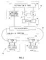
- FIG. 2A schematic block diagram of a network hub incorporating 1:N protection against both line and equipment failures constructed in accordance with the present invention is shown in FIG. 2 .
- the network hubillustrates the general application of the protection scheme of the invention to an optical hub.
- FIG. 3A detailed implementation of an embodiment of the general scheme of FIG. 2 is presented in FIG. 3 , described in more detail infra.
- the networkgenerally referenced 40 , comprises a network hub 42 and a plurality of access nodes 56 .
- the hubcomprises a switch 44 , line card with tunable transceiver 46 , N line cards with fixed wavelength transceivers 48 , a multiplexer/demultiplexer 50 and a 2 ⁇ 2 coupler/switch 52 .
- the access nodescomprise an OADM module 58 and one or more line cards 60 .
- the protection scheme illustratedis especially suited for optical ring networks logical star over physical ring network topology. Implementation of the protection scheme does not require any modification of the access nodes. Conventional access nodes may be used unchanged.
- the hubis modified to comprise only N+1 transceivers/line cards, assuming an N channel DWDM network. Each of the N transmitters operates using a different wavelength, i.e. ⁇ 1 to ⁇ N .
- an N+1 th line card 46provides protection for the N fixed wavelength line cards.
- This line cardcomprises a tunable transceiver whose wavelength for transmission and reception can be dynamically configured. At a minimum, the tunable transceiver can be configured to transmit and receive over any of the N wavelengths of the fixed line cards. Alternatively, the tunable transceiver can be adapted to communicate over additional wavelengths other than the wavelengths of the N fixed line cards.
- a tunable transceiver having a configurable wavelengthmay be constructed from a transmitter having a tunable laser and a receiver that incorporates a tunable filter.
- the output of the tunable transceiver and the multiplexed N channel data streamare optically coupled together, such as using a passive optical coupler, optically split and transmitted over both directions of the ring.
- an optical amplifiermay be used to boost the strength of the optical signal before being transmitted over the ring.
- an amplifier of the commonly known Erbium Doped Fiber Amplifier (EDFA) type of amplifiersmay be used.
- the receive signalis received from both directions of the ring.
- a 1 ⁇ 2 optical switchis employed to select one of the two input data streams to pass through to the receiver that are received from both directions of the ring. Since the hub comprises a single line card per wavelength, only one of the input data stream receive signals can be processed.
- the hubcomprises means for generating the appropriate control signal for the switch.
- the control for the optical switchmay be provided by control means with the optical switch itself, the electronic switch fabric 44 , separate management entity, control unit, etc.
- the criteria for selecting one of the two receive signalsmay be based on any suitable metric such as the signal yielding the higher Bit Error Rate (BER), the received signal with the higher quality, the signal with the higher power level, etc.
- Sensors adapted to read the power level of the received signalmay be placed on each of the links to the hub. The power readings are then used by the entity responsible for making the selection decision.
- the hubmay comprise means to detect a Loss of Signal (LOS) condition on the links and in such an event, configure the optical switch to select the working link (i.e. the link not in LOS condition).
- LOSLoss of Signal
- the output of the optical switchis then split and passed to both the tunable transceiver and the demultiplexers.
- the demultiplexerfunctions to separate the received signal into individual wavelengths which are subsequently input to the line cards according to the particular wavelength associated therewith.
- protection against a line failureis achieved since the data stream is split and transmitted in opposite directions of the ring to the access nodes.
- Equipment protectionis achieved by use of the tunable transceiver/line card which serves as a standby transceiver in the event of a failure of any of the fixed wavelength transceivers/line cards in the hub.
- the tunable transceivermay be utilized to increase the capacity of the hub in the absence of a failure. Once a failure is detected, however, it is configured to replace the failed line card.
- the splittermay be placed before the multiplexer, i.e. between the line cards and the multiplexer, to protect against the single point of failure of the splitter that exists otherwise. This is illustrated in the embodiments presented infra.
- FIG. 3A block diagram of a network hub incorporating 1:N protection against both line and equipment failures employing tunable transceivers constructed in accordance with the present invention is shown in FIG. 3 .
- the network hub shownis a closed system illustrating a detailed embodiment of the general application of the protection scheme shown in FIG. 2 .
- the hub, generally referenced 70is adapted to be connected in an optical ring network to communication links traveling in opposite directions, herein labeled East link 82 and West link 84 .
- the hubprovides protection against any single point of failure.
- the hubprovides a 1:N optical protection scheme for a logical star over physical ring network topology.
- the access nodesremain substantially unchanged relative to off the shelf conventional access nodes while the hub is modified to provide protection against both line and equipment failures.
- the hub 70comprises means for avoiding the single point of failure problem that would arise otherwise.
- the hubcomprises an electrical switch fabric 72 connected to N line cards 74 (assuming N number of DWDM channels) configured to wavelength ⁇ 1 . . . ⁇ N , N 1 ⁇ 2 coupler/switch modules 76 , dual multiplexer/demultiplexers 78 , dual 2 ⁇ (2 ⁇ 1) couplers 80 , a tunable line card 86 and associated 1 ⁇ 2 coupler/switch 92 .
- a management module 100provides administration, operation, control and management functions in the hub.
- the hubIn the transmit direction, the hub operates as follows. Data traffic output of the switch is steered to the appropriate line card, wherein each line card is adapted to generate an optical signal having a different fixed wavelength.
- the line cardmay be adapted to transmit and receive data at any rate using any desired format or protocol, e.g., 1 Gigabit Ethernet (GE), 10 GE, etc. with the limitation that all N+1 line cards communicate at the same rate.
- the N optical data streamsare then optically split and sent along two paths.
- the N signals in each pathare multiplexed via two multiplexers 78 and output to dual 2 ⁇ (2 ⁇ 1) couplers 80 .
- Each coupler 80comprises two 2 ⁇ 1 optical couplers, one for the transmit direction and one for the receive direction.
- the tunable transceiverreceives a data stream from the electronic switch fabric and generates an optical signal having a variable wavelength.
- the outputis input to the 1 ⁇ 2 coupler 92 whose output is input to the 2 ⁇ (2 ⁇ 1) couplers 80 .
- the 2 ⁇ (2 ⁇ 1) couplers 80function to combine the multiplexed signal with the output of the tunable transceiver and transmit the combined signal in opposite directions of the ring.
- One 2 ⁇ (2 ⁇ 1) coupleris connected to the East link and the other 2 ⁇ (2 ⁇ 1) coupler is connected to the West link.
- the tunable transceivercomprises a transmitter 88 having a tunable laser.
- the signals received from the East and West directionsare each split via 2 ⁇ (2 ⁇ 1) couplers 80 and input to the dual demultiplexers 78 and the switch 92 .
- the two receive signalsare demultiplexed and each wavelength is input to an optical switch 76 associated with a particular wavelength.
- the switchselects one or the other received signal and forwards it to the line card associated therewith.
- the criteria for selecting one of the two receive signalsmay be based on any suitable metric such as the signal yielding the higher Bit Error Rate (BER), the received signal with the higher quality, the signal with the higher power level, etc.
- Sensors adapted to read the power level of the received signalmay be placed on each of the links to the hub.
- the hubmay comprise means to detect a Loss of Signal (LOS) condition on the links and in such an event, configure the optical switch to select the working link (i.e. the link not in LOS condition).
- LOSLoss of Signal
- the split signals received from opposite directions of the ringare also input to an optical switch 92 .
- the switch 92makes the same selection as the N switches 76 depending on the chosen criteria.
- the signalis input to the receiver incorporating a tunable filter 90 .
- the control signals 98 provided by the electronic switch fabric 72function to configure the optical switches and the tunable transceiver.
- the control signalsdetermine the optical switch selection and enable and configure the wavelength of the tunable transceiver.
- the control signalsmay be provided by other entities in the hub such as the management module 100 , by the optical switches themselves, external control unit, etc.
- the LOS conditionis detected by means within the hub and the optical switches 76 , 92 are configured to receive the signal from the non-failed link.
- the tunable transceiveris configured to transmit and receive the wavelength of the failed channel.
- the electrical switch fabric 72is configured to send and receive data traffic to and from the tunable transceiver rather than the failed line card.
- the optical switchesmay be placed before the mux/demuxs, i.e. between the mux/demuxs and the 2 ⁇ (2 ⁇ 1) couplers, such that the signal output of each 2 ⁇ (2 ⁇ 1) coupler is input to the mux/demux.
- the optical switchesmay be placed before the mux/demuxs, i.e. between the mux/demuxs and the 2 ⁇ (2 ⁇ 1) couplers, such that the signal output of each 2 ⁇ (2 ⁇ 1) coupler is input to the mux/demux.
- the protection scheme of FIG. 3implements the 1:N optical protection scheme for line cards as a closed system.
- the electronic switch fabricin the event of a line card failure, is configured to direct the affected data to the standby tunable transceiver.
- the optical protection scheme of the present inventioncan also be applied to an open system that employs Optical/Electrical/Optical (OEO) conversion modules. In this case, the data traffic does not pass through the electronic switch fabric and a different configuration is used.
- OEOOptical/Electrical/Optical
- An OEOis an electrical based repeater used to regenerate the signal in the electrical domain.
- the OEO modulesfunction to convert the signal from optical to electrical and back to optical.
- the optical signal received by the OEOis converted from the optical domain to the electrical domain by an optical to electrical converter to yield an electrical signal.
- the electrical signalis then amplified and regenerated to yield a regenerated electrical signal.
- This signalis then converted to an optical signal by electrical to optical converter at a particular wavelength that is usually fixed. Benefits of electrical regeneration of the signal include wavelength conversion and the removal of noise from the ring.
- each channelis accessible electrically for other possible purposes.
- FIG. 4A block diagram of a network hub incorporating 1:N protection against both line and equipment failures employing tunable OEO modules constructed in accordance with the present invention is shown in FIG. 4 .
- This configurationemploys external add/drop multiplexers (ADMs) having any desired data rate, e.g., OC-48, OC-192, etc.
- ADMsexternal add/drop multiplexers
- Each external ADMsupports at least two data streams for protection purposes.
- the present inventionalso contemplates a hub configuration for providing 1:N protection that employs both line cards and OEO modules.
- the OEOs usedpreferably are (1) identical in the case that the ADMs are identical having the same data rate; (2) bit rate transparent wherein the ADMs are configured to different data rates; or (3) reconfigureable via software in conjunction with the use of tunable transceivers.
- the hubgenerally referenced 110 , comprises N OEO modules 112 (assuming N number of DWDM channels), N 1 ⁇ 2 coupler/switch modules 114 , dual multiplexer/demultiplexers 116 , dual 2 ⁇ (2 ⁇ 1) couplers 118 , an N ⁇ 1 optical switch 120 , tunable OEO module 122 and associated 1 ⁇ 2 coupler/switch 124 .
- a management module 136provides administration, operation, control and management functions in the hub.
- the tunable OEO modulecomprises a tunable transmitter and receiver at the network side.
- the operation of the hub 110is similar to that of the hub 70 of FIG. 3 with the difference being the use of OEO modules in communication with the external ADMs rather than line cards and the absence of an electrical switch fabric.
- Each OEO moduleis configured to convert the signal received from the external ADM to a different fixed wavelength.
- the multiplexed signalsare coupled with the signal from the tunable OEO module and the coupled signal sent in opposite directions over the ring, e.g., East link 126 and West link 128 .
- the external ADMs 130comprise a user interface 132 and at least two network interfaces 134 , 135 .
- the user interfaceis connected to a source of user data 138 .
- One network interface of each ADMis connected to one of N OEO modules 112 .
- the second network interface of each ADMis connected to an N ⁇ 1 optical switch 120 which is configured to couple one of the N inputs to the tunable OEO module 122 in the event of a failure.
- the optical switch 120functions to steer the spare OEO module to a particular ADM via the second network interface in the ADM.
- the output of the tunable OEO moduleis subsequently split for transmission over both directions of the ring.
- the management module 136is adapted to control the N ⁇ 1 optical switch 120 and configure the tunable OEO 122 to transmit and receive over the wavelength of the failed OEO module.
- the protection scheme of the present inventionreduces the number of line cards and OEO cards required to support a single hub DWDM ring network wherein a single channel is dropped/added at each access node.
- the savingsare significantly greater if any of the access nodes drops/adds several DWDM channels.
- a cardcomprising a 1 ⁇ 2 coupler and a 1 ⁇ 2 switch may be inserted at the output of the ADM to obtain the functionality of the scheme in FIG. 4 .
- the 1:N optical protection scheme of FIGS. 3 and 4can be applied to optical ring networks with the following limitations:
- FIG. 5A network diagram illustrating an example dual hub optical ring network wherein each hub provides 1:N protection against line and equipment failures in accordance with the present invention is shown in FIG. 5 .
- the networkgenerally referenced 140 , comprises two hubs 142 , 148 and a plurality of access nodes 144 each incorporating an OADM 146 .
- the protection scheme of the present inventioneliminates the use of double equipment in the hub, it does not support wavelength sharing on the ring. This is because different data signals having the same wavelength cannot arrive at the hub from opposite directions.
- the present inventionprovides a mechanism for providing the 1:N optical protection scheme in a dual hub ring network.
- one or more switchesare added to each hub that switch the signal received over the link either to the internal hub circuitry or through to the port connected to the opposite link.
- FIG. 6A block diagram of a network hub incorporating 1:N protection against both line and equipment failures employing tunable transceivers and adapted to operate in a dual hub optical ring network in accordance with the present invention is shown in FIG. 6 .
- the hub, generally referenced 150is adapted to be connected in a dual hub based optical ring network to communication links traveling in opposite directions, herein labeled East link 186 and West link 184 .
- the hubprovides a 1:N optical protection scheme for a logical star over physical ring network topology.
- the access nodesremain unchanged while the hub is modified to provide protection against both line and equipment failures.
- the hub 150comprises means for avoiding the single point of failure problem that would arise otherwise.
- the hubcomprises a switch 152 coupled to N line cards 154 (assuming N number of DWDM channels), N 1 ⁇ 2 coupler/switch modules 156 , dual multiplexer/demultiplexers 158 , 2 ⁇ (2 ⁇ 1) couplers 160 , a tunable line card 172 and associated 1 ⁇ 2 coupler/switch 178 .
- a management module 170provides administration, operation, control and management functions in the hub. It is noted that this portion of the hub is similar in construction and operation to that of FIG. 3 .
- a pair of optical switchesare added which control whether the receive signal is passed to the receiver or back out to the link in the opposite direction.
- the switches 162 , 164can be in either a working mode or a bypass (or standby) mode of operation. In FIG. 6 , the switches are shown in the working mode of operation. In operation, the ring comprises two such hubs with one being in working mode and the in standby mode. Under normal conditions, the hubs cannot be in the same operation mode at the same time, i.e. one node is always in a working mode and the other in standby.
- the hubIn the working mode, the hub operates as described in connection with the hub 70 shown in FIG. 3 , providing 1:N protection scheme as described supra.
- the optical switchescouple the East and West links together and the hub becomes transparent to the devices on the network.
- a means of communications between the two hubs and possible other entitiesis provided.
- the OADMs 168 , 182 and line cards 166 , 180 coupled respectively theretoprovide in band or out of band control communications channel.
- Data related to the operating state of each hubis communicated between the hubs. For example, when a failure in a working hub is detected, the standby hub is notified and a switchover is affected whereby the optical switches 162 , 164 in the standby hub are switched to place the hub in a working operation mode.
- FIG. 7A block diagram of a network hub incorporating 1:N protection against both line and equipment failures employing tunable OEO modules and adapted to operate in a dual hub optical ring network in accordance with the present invention is shown in FIG. 7 .
- This configurationemploys external ADMs having any desired data rate, e.g., OC-48, OC-192, etc.
- Each external ADMsupports at least two data streams for protection purposes.
- the hubgenerally referenced 190 , comprises N OEO modules 192 (assuming N number of DWDM channels), N 1 ⁇ 2 coupler/switch modules 194 , dual multiplexer/demultiplexers 196 , 2 ⁇ (2 ⁇ 1) couplers 198 , an N ⁇ 1 optical switch 204 , tunable OEO module 206 and associated 1 ⁇ 2 coupler/switch 208 .
- a management module 210provides administration, operation, control and management functions in the hub. It is noted that this portion of the hub is similar in construction and operation to that of FIG. 4 .
- the operation of the hub 190is similar to that of the hub 110 of FIG. 4 with the difference being the addition of optical switches 200 , 202 , internal OADMs 201 , 211 and OEO modules 213 , 215 .
- Each OEO moduleis configured to convert the signal received from the external ADM to a different fixed wavelength.
- the multiplexed signalsare coupled with the signal from the tunable OEO module and the coupled signal sent in opposite directions over the ring, e.g., East link 224 and West link 226 .
- the external ADMs 212comprise a user interface 214 and at least two network interfaces 216 , 218 .
- the user interfaceis connected to a source of user data.
- One network interface of each ADMis connected to one of N OEO modules.
- the second network interface of each ADMis connected to an N ⁇ 1 optical switch which is configured to couple one of the N inputs to the tunable OEO module in the event of a failure.
- the output of the tunable OEO moduleis subsequently split for transmission over both directions of the ring.
- the pair of optical switches 200 , 202control whether the signals received over the links are bypassed between each other or are passed to the hub circuitry. Similar to that of the hub 150 in FIG. 6 , the switches 200 , 202 can be either in a working mode or a bypass (or standby) mode of operation. In FIG. 7 , the switches are shown in the working mode of operation. In operation, the ring comprises two such hubs with one being in working mode and the other in standby mode. Under normal conditions, the hubs cannot be in the same operation mode at the same time, i.e. one node is always in a working mode and the other in standby.
- the hubIn working mode, the hub operates to provide 1:N protection as described supra.
- the switchescouple the East and West links together and the hub becomes transparent to the devices on the network.
- a means of communications between the two hubs and possible other entitiesis provided.
- the internal OADMs 201 , 211are coupled to OEO modules 213 , 215 , respectively, and provide an in band and/or out of band control communications channel.
- Data related to the operating state of each hubis communicated between the hubs. For example, a failure in a working hub is detected, the standby hub is notified and a switchover is affected whereby the switches 200 , 202 in the standby hub are thrown to place the hub in a working operation mode.
- the present inventionis not limited to the embodiments illustrated above.
- the closed system of FIG. 3 and the open system of FIG. 4may be combined to construct a hybrid system comprising portions of both systems.
- Such a hybrid systemcomprises one or more transceivers operative in combination with OEOs and external ADMs or the equivalent thereof.
- the systems of FIGS. 6 and 7may be combined whereby several transceivers (or line cards, etc.) are combined with several OEO modules in the same device.
Landscapes
- Engineering & Computer Science (AREA)
- Computer Networks & Wireless Communication (AREA)
- Signal Processing (AREA)
- Optical Communication System (AREA)
Abstract
Description
| Term | Definition | ||
| ADM | Add Drop Multiplexer | ||
| BER | Bit Error Rate | ||
| DWDM | Dense Wave Division Multiplexing | ||
| EDFA | Erbium Doped Fiber Amplifier | ||
| GE | Gigabit Ethernet | ||
| LAN | Local Area Network | ||
| LOS | Loss of Signal | ||
| MAN | Metropolitan Area Network | ||
| OADM | Optical Add Drop Multiplexer | ||
| OC | Optical Carrier | ||
| OEO | Optical-Electrical-Optical conversion | ||
| SNR | Signal to Noise Ratio | ||
| WAN | Wide Area Network | ||
| WDM | Wave Division Multiplexing | ||
- 1. The connection between the hub and each of the access nodes (i.e. OADMs within the nodes) is limited to point to point connections only. In other words, a dedicated wavelength must be provisioned for each access node. Normally, wavelengths cannot be shared without the use of two transceivers in the hub.
- 2. A dual hub topology may not employ the protection scheme of
FIGS. 3 and 4 . The use of the protection scheme is dependent on the location of the two hubs (same or different sites) and on the required connectivity between them.
Claims (30)
Priority Applications (1)
| Application Number | Priority Date | Filing Date | Title |
|---|---|---|---|
| US10/126,983US7072584B1 (en) | 2002-04-22 | 2002-04-22 | Network hub employing 1:N optical protection |
Applications Claiming Priority (1)
| Application Number | Priority Date | Filing Date | Title |
|---|---|---|---|
| US10/126,983US7072584B1 (en) | 2002-04-22 | 2002-04-22 | Network hub employing 1:N optical protection |
Publications (1)
| Publication Number | Publication Date |
|---|---|
| US7072584B1true US7072584B1 (en) | 2006-07-04 |
Family
ID=36613828
Family Applications (1)
| Application Number | Title | Priority Date | Filing Date |
|---|---|---|---|
| US10/126,983Expired - LifetimeUS7072584B1 (en) | 2002-04-22 | 2002-04-22 | Network hub employing 1:N optical protection |
Country Status (1)
| Country | Link |
|---|---|
| US (1) | US7072584B1 (en) |
Cited By (27)
| Publication number | Priority date | Publication date | Assignee | Title |
|---|---|---|---|---|
| US20050191054A1 (en)* | 2004-02-26 | 2005-09-01 | Yasuhiko Aoki | Optical network with selective mode switching |
| US20050213970A1 (en)* | 2004-03-29 | 2005-09-29 | Gaku Kimura | Relay transmission apparatus |
| US20060133804A1 (en)* | 2004-12-17 | 2006-06-22 | Tellabs Operations, Inc. | Method and apparatus for protecting optical signals within a wavelength division multiplexed environment |
| US20060210266A1 (en)* | 2005-03-18 | 2006-09-21 | Fujitsu Limited | Optical apparatus and optical cross connect apparatus |
| US20060253726A1 (en)* | 2005-05-06 | 2006-11-09 | Vikas Kukshya | Fault-tolerant architecture for a distributed control system |
| US20070211742A1 (en)* | 2006-01-30 | 2007-09-13 | Infinera Corporation | Application of hardware-based mailboxes in network transceivers and distributed approach for predictable software-based protection switching |
| US20090136233A1 (en)* | 2007-11-22 | 2009-05-28 | Yasuyuki Fukashiro | Optical transmission system and optical node |
| US7570886B1 (en)* | 2003-03-14 | 2009-08-04 | Afferton Thomas S | Network with optical bandwidth on demand |
| US20090304163A1 (en)* | 2008-06-05 | 2009-12-10 | Hon Hai Precision Industry Co., Ltd. | Call processing device and method |
| US20100002593A1 (en)* | 2008-07-04 | 2010-01-07 | Hon Hai Precision Industry Co., Ltd. | Method for detecting faults in gateway |
| US7680032B1 (en)* | 2003-12-19 | 2010-03-16 | Ciena Corporation | Bidirectional line switched partial rings, mesh networks, and methods of operation |
| US20110007654A1 (en)* | 2008-02-12 | 2011-01-13 | At&T Intellectual Property Ii, L.P. | Restoring Aggregated Circuits with Circuit Integrity Checks in a Hierarchical Network |
| US20130129340A1 (en)* | 2011-11-17 | 2013-05-23 | Finisar Corporation | Dual optical electrical conversion module |
| US20150078739A1 (en)* | 2013-09-17 | 2015-03-19 | Doron Handelman | Apparatus and methods for enabling recovery in optical networks |
| US20150125141A1 (en)* | 2013-11-06 | 2015-05-07 | Tellabs Operations, Inc. | Procedures, apparatuses, systems, and computer programs for providing optical network channel protection |
| EP2940911A1 (en)* | 2014-05-02 | 2015-11-04 | Deutsche Telekom AG | Optical transmission network and optical network elements for transmitting WDM signals |
| US9191101B2 (en) | 2011-06-21 | 2015-11-17 | Huawei Technologies Co., Ltd. | Optical line transmission protection system and method |
| US20150333821A1 (en)* | 2012-08-03 | 2015-11-19 | Nec Corporation | Multi-failure resolution optical node, optical communication system using same, and wavelength path switching method |
| US9325413B2 (en) | 2012-12-30 | 2016-04-26 | Doron Handelman | Apparatus and methods for enabling recovery from failures in optical networks |
| EP3091679A1 (en)* | 2015-05-05 | 2016-11-09 | Deutsche Telekom AG | Method for more effective data transmission in an optical telecommunication network in wavelength multiplex operation of optical wavelengths, wherein the optical telecommunication network has a plurality of network elements and two superordinate network nodes, optical telecommunication network, computer program and computer program product |
| WO2016192784A1 (en)* | 2015-06-02 | 2016-12-08 | Telefonaktiebolaget Lm Ericsson (Publ) | Transport network and method |
| US9910234B2 (en) | 2015-06-09 | 2018-03-06 | Alcatel-Lucent Usa Inc. | Datacenter interconnection system |
| CN108028812A (en)* | 2015-09-15 | 2018-05-11 | 阿尔卡特朗讯 | Method for operating line switching unit, line switching unit, line card and network node thereof |
| US20190312661A1 (en)* | 2016-06-20 | 2019-10-10 | Nippon Telegraph And Telephone Corporation | Optical transceiver and control method |
| US10536236B2 (en) | 2013-08-26 | 2020-01-14 | Coriant Operations, Inc. | Intranodal ROADM fiber management apparatuses, systems, and methods |
| EP3879727A1 (en)* | 2020-03-04 | 2021-09-15 | Corning Research & Development Corporation | Switching at a terminal end transceiver between primary and auxiliary communication paths |
| EP4009554A1 (en)* | 2020-12-01 | 2022-06-08 | Deutsche Telekom AG | System and method providing failure protection based on a faulty port in an aggregation network being an optical transport network |
Citations (9)
| Publication number | Priority date | Publication date | Assignee | Title |
|---|---|---|---|---|
| US5216666A (en) | 1991-12-12 | 1993-06-01 | Alcatel Network Systems, Inc. | 1:n ring-type signal protection apparatus |
| US5299293A (en) | 1991-04-02 | 1994-03-29 | Alcatel N.V. | Protection arrangement for an optical transmitter/receiver device |
| US5663949A (en) | 1994-11-15 | 1997-09-02 | Fujitsu Limited | Line protection switching system in duplexed fiber interface shelf |
| US5777761A (en)* | 1995-12-22 | 1998-07-07 | Mci Communications Corporation | System and method for photonic facility and line protection switching using wavelength translation |
| US6046832A (en) | 1997-12-04 | 2000-04-04 | Fishman; Ilya M. | System and method for protection of WDM/SONET networks |
| US20020145779A1 (en)* | 2001-03-16 | 2002-10-10 | Strasser Thomas Andrew | Method and apparatus for interconnecting a plurality of optical transducers with a wavelength division multiplexed optical switch |
| US6512611B1 (en) | 1999-12-23 | 2003-01-28 | Nortel Networks Limited | Method of deactivating protection fiber resources in optical ring networks |
| US6744760B1 (en)* | 1999-07-23 | 2004-06-01 | Nortel Networks Limited | Node configurations within communication systems |
| US20040131366A1 (en)* | 2000-03-16 | 2004-07-08 | Hideaki Tsushima | Wavelength tunable optical transmitter, optical transponder and optical transmission system |
- 2002
- 2002-04-22USUS10/126,983patent/US7072584B1/ennot_activeExpired - Lifetime
Patent Citations (9)
| Publication number | Priority date | Publication date | Assignee | Title |
|---|---|---|---|---|
| US5299293A (en) | 1991-04-02 | 1994-03-29 | Alcatel N.V. | Protection arrangement for an optical transmitter/receiver device |
| US5216666A (en) | 1991-12-12 | 1993-06-01 | Alcatel Network Systems, Inc. | 1:n ring-type signal protection apparatus |
| US5663949A (en) | 1994-11-15 | 1997-09-02 | Fujitsu Limited | Line protection switching system in duplexed fiber interface shelf |
| US5777761A (en)* | 1995-12-22 | 1998-07-07 | Mci Communications Corporation | System and method for photonic facility and line protection switching using wavelength translation |
| US6046832A (en) | 1997-12-04 | 2000-04-04 | Fishman; Ilya M. | System and method for protection of WDM/SONET networks |
| US6744760B1 (en)* | 1999-07-23 | 2004-06-01 | Nortel Networks Limited | Node configurations within communication systems |
| US6512611B1 (en) | 1999-12-23 | 2003-01-28 | Nortel Networks Limited | Method of deactivating protection fiber resources in optical ring networks |
| US20040131366A1 (en)* | 2000-03-16 | 2004-07-08 | Hideaki Tsushima | Wavelength tunable optical transmitter, optical transponder and optical transmission system |
| US20020145779A1 (en)* | 2001-03-16 | 2002-10-10 | Strasser Thomas Andrew | Method and apparatus for interconnecting a plurality of optical transducers with a wavelength division multiplexed optical switch |
Cited By (46)
| Publication number | Priority date | Publication date | Assignee | Title |
|---|---|---|---|---|
| US7570886B1 (en)* | 2003-03-14 | 2009-08-04 | Afferton Thomas S | Network with optical bandwidth on demand |
| US7680032B1 (en)* | 2003-12-19 | 2010-03-16 | Ciena Corporation | Bidirectional line switched partial rings, mesh networks, and methods of operation |
| US7369765B2 (en)* | 2004-02-26 | 2008-05-06 | Fujitsu Limited | Optical network with selective mode switching |
| US20050191054A1 (en)* | 2004-02-26 | 2005-09-01 | Yasuhiko Aoki | Optical network with selective mode switching |
| US7548693B2 (en)* | 2004-03-29 | 2009-06-16 | Fujitsu Limited | Relay transmission apparatus |
| US20050213970A1 (en)* | 2004-03-29 | 2005-09-29 | Gaku Kimura | Relay transmission apparatus |
| US20060133804A1 (en)* | 2004-12-17 | 2006-06-22 | Tellabs Operations, Inc. | Method and apparatus for protecting optical signals within a wavelength division multiplexed environment |
| US20060210266A1 (en)* | 2005-03-18 | 2006-09-21 | Fujitsu Limited | Optical apparatus and optical cross connect apparatus |
| US7764881B2 (en)* | 2005-03-18 | 2010-07-27 | Fujitsu Limited | Optical apparatus and optical cross connect apparatus |
| US20060253726A1 (en)* | 2005-05-06 | 2006-11-09 | Vikas Kukshya | Fault-tolerant architecture for a distributed control system |
| US20070211742A1 (en)* | 2006-01-30 | 2007-09-13 | Infinera Corporation | Application of hardware-based mailboxes in network transceivers and distributed approach for predictable software-based protection switching |
| US8477596B2 (en)* | 2006-01-30 | 2013-07-02 | Infinera Corporation | Application of hardware-based mailboxes in network transceivers and distributed approach for predictable software-based protection switching |
| US20090136233A1 (en)* | 2007-11-22 | 2009-05-28 | Yasuyuki Fukashiro | Optical transmission system and optical node |
| US8165467B2 (en)* | 2007-11-22 | 2012-04-24 | Hitachi, Ltd. | Optical transmission system and optical node |
| US9007890B2 (en) | 2008-02-12 | 2015-04-14 | At&T Intellectual Property Ii, L.P. | Restoring aggregated circuits with circuit integrity checks in a hierarchical network |
| US8451712B2 (en)* | 2008-02-12 | 2013-05-28 | At&T Intellectual Property Ii, L.P. | Restoring aggregated circuits with circuit integrity checks in a hierarchical network |
| US20110007654A1 (en)* | 2008-02-12 | 2011-01-13 | At&T Intellectual Property Ii, L.P. | Restoring Aggregated Circuits with Circuit Integrity Checks in a Hierarchical Network |
| US7826347B2 (en)* | 2008-06-05 | 2010-11-02 | Hon Hai Precision Industry Co., Ltd. | Call processing device and method |
| US20090304163A1 (en)* | 2008-06-05 | 2009-12-10 | Hon Hai Precision Industry Co., Ltd. | Call processing device and method |
| US20100002593A1 (en)* | 2008-07-04 | 2010-01-07 | Hon Hai Precision Industry Co., Ltd. | Method for detecting faults in gateway |
| US9191101B2 (en) | 2011-06-21 | 2015-11-17 | Huawei Technologies Co., Ltd. | Optical line transmission protection system and method |
| US9054796B2 (en)* | 2011-11-17 | 2015-06-09 | Finisar Corporation | Dual optical electrical conversion module |
| US20130129340A1 (en)* | 2011-11-17 | 2013-05-23 | Finisar Corporation | Dual optical electrical conversion module |
| US9590725B2 (en)* | 2012-08-03 | 2017-03-07 | Nec Corporation | Multi-failure resolution optical node, optical communication system using same, and wavelength path switching method |
| US20150333821A1 (en)* | 2012-08-03 | 2015-11-19 | Nec Corporation | Multi-failure resolution optical node, optical communication system using same, and wavelength path switching method |
| US9325413B2 (en) | 2012-12-30 | 2016-04-26 | Doron Handelman | Apparatus and methods for enabling recovery from failures in optical networks |
| US10536236B2 (en) | 2013-08-26 | 2020-01-14 | Coriant Operations, Inc. | Intranodal ROADM fiber management apparatuses, systems, and methods |
| US9853721B2 (en) | 2013-09-17 | 2017-12-26 | Doron Handelman | Apparatus and methods for enabling recovery in optical networks |
| US9344187B2 (en)* | 2013-09-17 | 2016-05-17 | Doron Handelman | Apparatus and methods for enabling recovery in optical networks |
| US20150078739A1 (en)* | 2013-09-17 | 2015-03-19 | Doron Handelman | Apparatus and methods for enabling recovery in optical networks |
| US9723385B2 (en)* | 2013-11-06 | 2017-08-01 | Coriant Operations, LLC | Procedures, apparatuses, systems, and computer programs for providing optical network channel protection |
| US20150125141A1 (en)* | 2013-11-06 | 2015-05-07 | Tellabs Operations, Inc. | Procedures, apparatuses, systems, and computer programs for providing optical network channel protection |
| EP2940911A1 (en)* | 2014-05-02 | 2015-11-04 | Deutsche Telekom AG | Optical transmission network and optical network elements for transmitting WDM signals |
| EP3091679A1 (en)* | 2015-05-05 | 2016-11-09 | Deutsche Telekom AG | Method for more effective data transmission in an optical telecommunication network in wavelength multiplex operation of optical wavelengths, wherein the optical telecommunication network has a plurality of network elements and two superordinate network nodes, optical telecommunication network, computer program and computer program product |
| WO2016192784A1 (en)* | 2015-06-02 | 2016-12-08 | Telefonaktiebolaget Lm Ericsson (Publ) | Transport network and method |
| US10667024B2 (en) | 2015-06-02 | 2020-05-26 | Telefonaktiebolaget Lm Ericsson (Publ) | Transport network and method |
| US10261276B2 (en) | 2015-06-09 | 2019-04-16 | Nokia Of America Corporation | Datacenter interconnection system |
| US9910234B2 (en) | 2015-06-09 | 2018-03-06 | Alcatel-Lucent Usa Inc. | Datacenter interconnection system |
| US20180234357A1 (en)* | 2015-09-15 | 2018-08-16 | Alcatel Lucent | Method for operating a line switching component, line switching component, line card, and network node thereof |
| US10419364B2 (en)* | 2015-09-15 | 2019-09-17 | Alcatel Lucent | Method for operating a line switching component, line switching component, line card, and network node thereof |
| JP2018527861A (en)* | 2015-09-15 | 2018-09-20 | アルカテル−ルーセント | Method for operating line switching components, line switching components, line cards, and network nodes thereof |
| CN108028812A (en)* | 2015-09-15 | 2018-05-11 | 阿尔卡特朗讯 | Method for operating line switching unit, line switching unit, line card and network node thereof |
| US20190312661A1 (en)* | 2016-06-20 | 2019-10-10 | Nippon Telegraph And Telephone Corporation | Optical transceiver and control method |
| US10594431B2 (en)* | 2016-06-20 | 2020-03-17 | Nippon Telegraph And Telephone Corporation | Optical transceiver and control method |
| EP3879727A1 (en)* | 2020-03-04 | 2021-09-15 | Corning Research & Development Corporation | Switching at a terminal end transceiver between primary and auxiliary communication paths |
| EP4009554A1 (en)* | 2020-12-01 | 2022-06-08 | Deutsche Telekom AG | System and method providing failure protection based on a faulty port in an aggregation network being an optical transport network |
Similar Documents
| Publication | Publication Date | Title |
|---|---|---|
| US7072584B1 (en) | Network hub employing 1:N optical protection | |
| US6850663B2 (en) | Equipments including transponder for optical fiber transmission | |
| US5986783A (en) | Method and apparatus for operation, protection, and restoration of heterogeneous optical communication networks | |
| US6331906B1 (en) | Method and apparatus for operation, protection and restoration of heterogeneous optical communication networks | |
| EP0716521B1 (en) | Ring network communication structure on an optical carrier and reconfigurable node for said structure | |
| US6542268B1 (en) | Optical channel cross connect for telecommunication systems in wdm technology (wavelength division multiplexing) having a double spatial switching structure of optical flows strictly not blocking and interposed functional units operating on single channels | |
| US7321729B2 (en) | Optical ring network with selective signal regeneration and wavelength conversion | |
| US6839514B1 (en) | Method and apparatus for operation, protection, and restoration of heterogeneous optical communication networks | |
| US20110116790A1 (en) | Wavelength path communication node apparatus, wavelength path communication control method, program, and recording medium | |
| EP1536583B1 (en) | Optical ring network with optical subnets | |
| US20050286896A1 (en) | Hybrid optical ring network | |
| US20020181037A1 (en) | Failure protection switching in optical network | |
| US6968130B1 (en) | System and method for fully utilizing available optical transmission spectrum in optical networks | |
| US20050019034A1 (en) | System and method for communicating optical traffic between ring networks | |
| US6735392B1 (en) | System and method for transmitting and restoring an optical signal | |
| US20050002671A1 (en) | Wavelength division multiplexed optical transmission systems, apparatuses, and methods | |
| EP1014613A2 (en) | Shared optical protection in an optical communications network | |
| US20050196169A1 (en) | System and method for communicating traffic between optical rings | |
| US20020106146A1 (en) | Optical network structure | |
| US20050036444A1 (en) | WDM bidirectional add/drop self-healing hubbed ring network | |
| EP1231811A2 (en) | Transparent optical-electronic-optical switch | |
| US7305184B2 (en) | Method and system for management of directly connected optical components |
Legal Events
| Date | Code | Title | Description |
|---|---|---|---|
| AS | Assignment | Owner name:ATRICA IRELAND LIMITED, IRELAND Free format text:ASSIGNMENT OF ASSIGNORS INTEREST;ASSIGNORS:LICHTMAN, EYAL;SHABTAY, LIOR;REEL/FRAME:012827/0890 Effective date:20020415 | |
| AS | Assignment | Owner name:VENTURE LENDING & LEASING III, INC., CALIFORNIA Free format text:SECURITY INTEREST;ASSIGNOR:ARTICA IRELAND LIMITED;REEL/FRAME:013609/0057 Effective date:20021213 | |
| AS | Assignment | Owner name:VENTURE LENDING & LEASING III, INC., CALIFORNIA Free format text:CORRECTION TO THE SPELLING OF THE CONVEYING PARTY;ASSIGNOR:ATRICA IRELAND LIMITED;REEL/FRAME:014174/0374 Effective date:20021213 | |
| AS | Assignment | Owner name:ATRICA ISRAEL LTD., ISRAEL Free format text:ASSIGNMENT OF ASSIGNORS INTEREST;ASSIGNOR:ATRICA IRELAND LIMITED;REEL/FRAME:016038/0920 Effective date:20041228 | |
| AS | Assignment | Owner name:ATRICA IRELAND LIMITED, CALIFORNIA Free format text:RELEASE BY SECURED PARTY;ASSIGNOR:VENTURE LENDING & LEASING III, INC.;REEL/FRAME:017024/0716 Effective date:20060109 | |
| STCF | Information on status: patent grant | Free format text:PATENTED CASE | |
| AS | Assignment | Owner name:SPVC VI, LLC, MINNESOTA Free format text:SECURITY AGREEMENT;ASSIGNOR:ATRICA ISRAEL LTD.;REEL/FRAME:019511/0116 Effective date:20070530 Owner name:GUNNALLEN VENTURE PARTNERS X-A, LLC, FLORIDA Free format text:SECURITY AGREEMENT;ASSIGNOR:ATRICA ISRAEL LTD.;REEL/FRAME:019511/0116 Effective date:20070530 Owner name:JK&B CAPITAL FUND IV, L.P., ILLINOIS Free format text:SECURITY AGREEMENT;ASSIGNOR:ATRICA ISRAEL LTD.;REEL/FRAME:019511/0116 Effective date:20070530 Owner name:JK&B CAPITAL FUND IV, Q.I.P., ILLINOIS Free format text:SECURITY AGREEMENT;ASSIGNOR:ATRICA ISRAEL LTD.;REEL/FRAME:019511/0116 Effective date:20070530 Owner name:BENHAMOU GLOBAL INVESTORS, LLC, CALIFORNIA Free format text:SECURITY AGREEMENT;ASSIGNOR:ATRICA ISRAEL LTD.;REEL/FRAME:019511/0116 Effective date:20070530 Owner name:LITUNG VENTURE CAPITAL CORPORATION, TAIWAN Free format text:SECURITY AGREEMENT;ASSIGNOR:ATRICA ISRAEL LTD.;REEL/FRAME:019511/0116 Effective date:20070530 Owner name:INNOVACOM 4, CALIFORNIA Free format text:SECURITY AGREEMENT;ASSIGNOR:ATRICA ISRAEL LTD.;REEL/FRAME:019511/0116 Effective date:20070530 Owner name:CADOGAN, WILLIAM J., FLORIDA Free format text:SECURITY AGREEMENT;ASSIGNOR:ATRICA ISRAEL LTD.;REEL/FRAME:019511/0116 Effective date:20070530 Owner name:GEMINI ISRAEL III LP, ISRAEL Free format text:SECURITY AGREEMENT;ASSIGNOR:ATRICA ISRAEL LTD.;REEL/FRAME:019511/0116 Effective date:20070530 Owner name:GEMINI ISRAEL III OVERFLOW FUND L.P., ISRAEL Free format text:SECURITY AGREEMENT;ASSIGNOR:ATRICA ISRAEL LTD.;REEL/FRAME:019511/0116 Effective date:20070530 Owner name:GEMINI ISRAEL III PARALLEL FUND L.P., ISRAEL Free format text:SECURITY AGREEMENT;ASSIGNOR:ATRICA ISRAEL LTD.;REEL/FRAME:019511/0116 Effective date:20070530 Owner name:GEMINI PARTNER INVESTORS L.P., ISRAEL Free format text:SECURITY AGREEMENT;ASSIGNOR:ATRICA ISRAEL LTD.;REEL/FRAME:019511/0116 Effective date:20070530 Owner name:RANDOLPH ASSOCIATES, ILLINOIS Free format text:SECURITY AGREEMENT;ASSIGNOR:ATRICA ISRAEL LTD.;REEL/FRAME:019511/0116 Effective date:20070530 Owner name:LEGEND VENTURES I, L.P., MARYLAND Free format text:SECURITY AGREEMENT;ASSIGNOR:ATRICA ISRAEL LTD.;REEL/FRAME:019511/0116 Effective date:20070530 Owner name:RANDOLPH STREET PARTNERS V, ILLINOIS Free format text:SECURITY AGREEMENT;ASSIGNOR:ATRICA ISRAEL LTD.;REEL/FRAME:019511/0116 Effective date:20070530 Owner name:HSP MULTIPLE STRATEGY FUND LLC, CALIFORNIA Free format text:SECURITY AGREEMENT;ASSIGNOR:ATRICA ISRAEL LTD.;REEL/FRAME:019511/0116 Effective date:20070530 Owner name:TOMASETTA FAMILY PARTNERSHIP LP, CALIFORNIA Free format text:SECURITY AGREEMENT;ASSIGNOR:ATRICA ISRAEL LTD.;REEL/FRAME:019511/0116 Effective date:20070530 Owner name:WAVELAND TECHNOLOGY PARTNERS, L.P., CALIFORNIA Free format text:SECURITY AGREEMENT;ASSIGNOR:ATRICA ISRAEL LTD.;REEL/FRAME:019511/0116 Effective date:20070530 Owner name:IRA DEHYIMY C/O VITESSE SEMICONDUCTOR CORP., CALIF Free format text:SECURITY AGREEMENT;ASSIGNOR:ATRICA ISRAEL LTD.;REEL/FRAME:019511/0116 Effective date:20070530 Owner name:THE CHALLENGE FUND-ETGAR II, LP, ISRAEL Free format text:SECURITY AGREEMENT;ASSIGNOR:ATRICA ISRAEL LTD.;REEL/FRAME:019511/0116 Effective date:20070530 Owner name:SPVC VI, LLC,MINNESOTA Free format text:SECURITY AGREEMENT;ASSIGNOR:ATRICA ISRAEL LTD.;REEL/FRAME:019511/0116 Effective date:20070530 Owner name:GUNNALLEN VENTURE PARTNERS X-A, LLC,FLORIDA Free format text:SECURITY AGREEMENT;ASSIGNOR:ATRICA ISRAEL LTD.;REEL/FRAME:019511/0116 Effective date:20070530 Owner name:JK&B CAPITAL FUND IV, L.P.,ILLINOIS Free format text:SECURITY AGREEMENT;ASSIGNOR:ATRICA ISRAEL LTD.;REEL/FRAME:019511/0116 Effective date:20070530 Owner name:JK&B CAPITAL FUND IV, Q.I.P.,ILLINOIS Free format text:SECURITY AGREEMENT;ASSIGNOR:ATRICA ISRAEL LTD.;REEL/FRAME:019511/0116 Effective date:20070530 Owner name:BENHAMOU GLOBAL INVESTORS, LLC,CALIFORNIA Free format text:SECURITY AGREEMENT;ASSIGNOR:ATRICA ISRAEL LTD.;REEL/FRAME:019511/0116 Effective date:20070530 Owner name:LITUNG VENTURE CAPITAL CORPORATION,TAIWAN Free format text:SECURITY AGREEMENT;ASSIGNOR:ATRICA ISRAEL LTD.;REEL/FRAME:019511/0116 Effective date:20070530 Owner name:INNOVACOM 4,CALIFORNIA Free format text:SECURITY AGREEMENT;ASSIGNOR:ATRICA ISRAEL LTD.;REEL/FRAME:019511/0116 Effective date:20070530 Owner name:CADOGAN, WILLIAM J.,FLORIDA Free format text:SECURITY AGREEMENT;ASSIGNOR:ATRICA ISRAEL LTD.;REEL/FRAME:019511/0116 Effective date:20070530 Owner name:GEMINI ISRAEL III LP,ISRAEL Free format text:SECURITY AGREEMENT;ASSIGNOR:ATRICA ISRAEL LTD.;REEL/FRAME:019511/0116 Effective date:20070530 Owner name:GEMINI ISRAEL III OVERFLOW FUND L.P.,ISRAEL Free format text:SECURITY AGREEMENT;ASSIGNOR:ATRICA ISRAEL LTD.;REEL/FRAME:019511/0116 Effective date:20070530 Owner name:GEMINI ISRAEL III PARALLEL FUND L.P.,ISRAEL Free format text:SECURITY AGREEMENT;ASSIGNOR:ATRICA ISRAEL LTD.;REEL/FRAME:019511/0116 Effective date:20070530 Owner name:GEMINI PARTNER INVESTORS L.P.,ISRAEL Free format text:SECURITY AGREEMENT;ASSIGNOR:ATRICA ISRAEL LTD.;REEL/FRAME:019511/0116 Effective date:20070530 Owner name:RANDOLPH ASSOCIATES,ILLINOIS Free format text:SECURITY AGREEMENT;ASSIGNOR:ATRICA ISRAEL LTD.;REEL/FRAME:019511/0116 Effective date:20070530 Owner name:LEGEND VENTURES I, L.P.,MARYLAND Free format text:SECURITY AGREEMENT;ASSIGNOR:ATRICA ISRAEL LTD.;REEL/FRAME:019511/0116 Effective date:20070530 Owner name:RANDOLPH STREET PARTNERS V,ILLINOIS Free format text:SECURITY AGREEMENT;ASSIGNOR:ATRICA ISRAEL LTD.;REEL/FRAME:019511/0116 Effective date:20070530 Owner name:HSP MULTIPLE STRATEGY FUND LLC,CALIFORNIA Free format text:SECURITY AGREEMENT;ASSIGNOR:ATRICA ISRAEL LTD.;REEL/FRAME:019511/0116 Effective date:20070530 Owner name:TOMASETTA FAMILY PARTNERSHIP LP,CALIFORNIA Free format text:SECURITY AGREEMENT;ASSIGNOR:ATRICA ISRAEL LTD.;REEL/FRAME:019511/0116 Effective date:20070530 Owner name:WAVELAND TECHNOLOGY PARTNERS, L.P.,CALIFORNIA Free format text:SECURITY AGREEMENT;ASSIGNOR:ATRICA ISRAEL LTD.;REEL/FRAME:019511/0116 Effective date:20070530 Owner name:IRA DEHYIMY C/O VITESSE SEMICONDUCTOR CORP.,CALIFO Free format text:SECURITY AGREEMENT;ASSIGNOR:ATRICA ISRAEL LTD.;REEL/FRAME:019511/0116 Effective date:20070530 Owner name:THE CHALLENGE FUND-ETGAR II, LP,ISRAEL Free format text:SECURITY AGREEMENT;ASSIGNOR:ATRICA ISRAEL LTD.;REEL/FRAME:019511/0116 Effective date:20070530 | |
| FEPP | Fee payment procedure | Free format text:PAYOR NUMBER ASSIGNED (ORIGINAL EVENT CODE: ASPN); ENTITY STATUS OF PATENT OWNER: LARGE ENTITY | |
| AS | Assignment | Owner name:ATRICA ISRAEL, LTD., ISRAEL Free format text:RELEASE BY SECURED PARTY;ASSIGNORS:SPVC VI, LLC;GUNNALLEN VENTURE PARTNERS X-A, LLC;JK&B CAPITAL FUND IV, L.P.;AND OTHERS;REEL/FRAME:020417/0090 Effective date:20080104 Owner name:ATRICA ISRAEL, LTD.,ISRAEL Free format text:RELEASE BY SECURED PARTY;ASSIGNORS:SPVC VI, LLC;GUNNALLEN VENTURE PARTNERS X-A, LLC;JK&B CAPITAL FUND IV, L.P.;AND OTHERS;REEL/FRAME:020417/0090 Effective date:20080104 | |
| FPAY | Fee payment | Year of fee payment:4 | |
| AS | Assignment | Owner name:NOKIA SIEMENS NETWORKS ETHERNET SOLUTIONS LTD., IS Free format text:CHANGE OF NAME;ASSIGNOR:ATRICA ISRAEL LTD.;REEL/FRAME:028264/0642 Effective date:20081001 | |
| FPAY | Fee payment | Year of fee payment:8 | |
| MAFP | Maintenance fee payment | Free format text:PAYMENT OF MAINTENANCE FEE, 12TH YEAR, LARGE ENTITY (ORIGINAL EVENT CODE: M1553) Year of fee payment:12 |