US7072407B2 - Combination power and full duplex data cable - Google Patents
Combination power and full duplex data cableDownload PDFInfo
- Publication number
- US7072407B2 US7072407B2US09/753,747US75374700AUS7072407B2US 7072407 B2US7072407 B2US 7072407B2US 75374700 AUS75374700 AUS 75374700AUS 7072407 B2US7072407 B2US 7072407B2
- Authority
- US
- United States
- Prior art keywords
- cable
- power
- coaxial
- data
- converter
- Prior art date
- Legal status (The legal status is an assumption and is not a legal conclusion. Google has not performed a legal analysis and makes no representation as to the accuracy of the status listed.)
- Expired - Lifetime, expires
Links
Images


Classifications
- H—ELECTRICITY
- H04—ELECTRIC COMMUNICATION TECHNIQUE
- H04B—TRANSMISSION
- H04B3/00—Line transmission systems
- H04B3/54—Systems for transmission via power distribution lines
- H04B3/548—Systems for transmission via power distribution lines the power on the line being DC
- H—ELECTRICITY
- H04—ELECTRIC COMMUNICATION TECHNIQUE
- H04B—TRANSMISSION
- H04B3/00—Line transmission systems
- H04B3/54—Systems for transmission via power distribution lines
- H04B3/542—Systems for transmission via power distribution lines the information being in digital form
- H—ELECTRICITY
- H04—ELECTRIC COMMUNICATION TECHNIQUE
- H04B—TRANSMISSION
- H04B2203/00—Indexing scheme relating to line transmission systems
- H04B2203/54—Aspects of powerline communications not already covered by H04B3/54 and its subgroups
- H04B2203/5404—Methods of transmitting or receiving signals via power distribution lines
- H04B2203/5425—Methods of transmitting or receiving signals via power distribution lines improving S/N by matching impedance, noise reduction, gain control
- H—ELECTRICITY
- H04—ELECTRIC COMMUNICATION TECHNIQUE
- H04B—TRANSMISSION
- H04B2203/00—Indexing scheme relating to line transmission systems
- H04B2203/54—Aspects of powerline communications not already covered by H04B3/54 and its subgroups
- H04B2203/5429—Applications for powerline communications
- H04B2203/5445—Local network
- H—ELECTRICITY
- H04—ELECTRIC COMMUNICATION TECHNIQUE
- H04B—TRANSMISSION
- H04B2203/00—Indexing scheme relating to line transmission systems
- H04B2203/54—Aspects of powerline communications not already covered by H04B3/54 and its subgroups
- H04B2203/5462—Systems for power line communications
- H04B2203/547—Systems for power line communications via DC power distribution
- H—ELECTRICITY
- H04—ELECTRIC COMMUNICATION TECHNIQUE
- H04B—TRANSMISSION
- H04B2203/00—Indexing scheme relating to line transmission systems
- H04B2203/54—Aspects of powerline communications not already covered by H04B3/54 and its subgroups
- H04B2203/5462—Systems for power line communications
- H04B2203/5483—Systems for power line communications using coupling circuits
- H—ELECTRICITY
- H04—ELECTRIC COMMUNICATION TECHNIQUE
- H04B—TRANSMISSION
- H04B2203/00—Indexing scheme relating to line transmission systems
- H04B2203/54—Aspects of powerline communications not already covered by H04B3/54 and its subgroups
- H04B2203/5462—Systems for power line communications
- H04B2203/5491—Systems for power line communications using filtering and bypassing
Definitions
- the present inventionrelates to the field of Neighborhood Area Networks (NANs), and more specifically to NANs incorporating coaxial cable to increase the data rate and distance of the NAN.
- NANsNeighborhood Area Networks
- LANsLocal area networks
- Numerous LANsuse the Ethernet standards set forth by the IEEE 802.3. Under this standard, 100Base-TX (100 Mbit) baseband data signals are transferred over unshielded twisted pairs (UTP) such as Cat-5. Under Ethernet standards, transmission distances are limited to the IEEE 802.3-specified 100 meter maximum. The 100 meter maximum is based upon CSMA/CD collision domain and Cat-5 attenuation criteria. When significantly longer distances are required, fiber optic cable is employed.
- Fiber optic cablehas much higher capital and outdoor installation costs in order to protect the delicate fibers. Fiber transceiver nodes are also more expensive than for UTP, such as Cat-5. Consequently, economics have encouraged the widespread proliferation of 100Base-TX Cat-5-based LAN systems. Fiber optic systems are typically used only for longer trunk lines between work groups. Fiber cable is also limited in that it is a dielectric material and cannot conduct electrical power. Thus, fiber cable cannot be used to supply electric power to remote sites.
- LANsusually employ a conventional AC power system to supply power to hubs, repeaters, switches, and other network components. Installation of certain components must be made in locations that are not conveniently located near AC power sources. In such conditions, power must be supplied either by installing separate power wires, by using batteries, or by employing the Cat-5 wiring itself.
- the total equivalent resistance for the power circuitcomprises the sum of the source and return wire resistances.
- a six (6) Watt switch operating at 3.3 Vconsumes nearly 2A, which in turn dictates that a 100 meter length of Cat-5 cable would drop nearly 34 V and 60 Watts in the wire alone.
- U.S. Pat. No. 5,994,998describes an alternate technique for using the signal pairs in a Cat-5 cable to carry power. This reduces the resistance by a factor of two (2).
- this techniqueis impractical for longer distances because of the degradation of the signal to noise ratio. Such degradation is caused by increased noise generated by power supply current through greater lengths of cable in addition to the decreased signal level.
- Another disadvantage of this techniqueis the high cost of quality inductors. The relatively expensive inductors are required to isolate signals from power without seriously altering the delicate IEEE 802.32u specification for 100Base-TX signals.
- CATVCommunity Antenna TV
- the CATVis not a LAN in the Ethernet sense and usually carries signals as modulated radio frequency (RF) in the down link direction rather than bi-directional baseband data signals.
- RFradio frequency
- the CATVemploys a power distribution system to power RF amplifiers at periodic distances to compensate for attenuation at VHF and UHF frequencies.
- Amplifier system poweris usually supplied by AC or DC power distribution systems comprising either: 1) the outer shield and inner conductor of the cable itself; or 2) separate power wires running with the cable.
- U.S. Pat. No. 3,987,240describes a CATV power system of the first method in which DC power of one polarity is coupled to the center conductor of a coaxial cable. The opposite polarity is coupled to the shield of the coaxial cable.
- the high frequency TV signalsare also conducted over the same coaxial cable with high quality chokes and filters used to separate the power from the RF signals at the amplifiers.
- the disadvantage of the first methodis the relatively high cost and quality of the chokes and filters required to effectively separate the power from the RF in the face of power system noise and transients.
- the second methoduses separate power distribution wires to avoid the costs of quality chokes and filters.
- a NANdiffers from a LAN in that a NAN averages greater distances between users and requires a server having greater capacity. A NAN may therefore exceed the 100 meter maximum length specified by the IEEE for Cat-5 cable.
- a NANfurther differs form a LAN in that the NAN requires that a power distribution system be integrated with the data distribution system to power boosters, repeaters, hubs and switches.
- a NANalso differs from a LAN in that the NAN deploys outdoor aerial and underground burial techniques and technology. Both aerial and underground burial techniques are required to give a NAN the flexibility for networking residences and businesses in neighborhoods.
- coaxial cablehas advantages over Cat-5 cable such as lower impedance and lower attenuation.
- the attenuation of low loss coaxial cableis 60% less than that of Cat-5 (to 100BaseTX signals) and provides a 40–50% increase in range.
- Coaxial cableis also mechanically a hardier connection due to the thicker spacing in its shielding and sheath.
- coaxial cableis more robust and more resistant to physical impact than Cat-5 cable.
- Coaxial cableis, therefore, superior in enduring environmental conditions, including without limitation underground burial.
- the typical NANwould benefit from successful incorporation of coaxial cable therein.
- conventional specificationsdo not support the use of coaxial cable in a NAN.
- the present inventionprovides a dual coaxial data and DC power transmission system that exceeds transmission distances found with use of conventional Cat-5 cable. Since the 802.3u specification is not usable for the coaxial media, the present invention provides a converter for converting 100BaseT differential Cat-5 (100 ohm impedance signals) to single ended coaxial (50 ohm impedance) signals and back again.
- the present inventionintegrates power distribution throughout the coaxial cables of a NAN to remote sites.
- the shield of one coaxial cablemay be the positive polarity and the shield of a second coaxial cable may be the negative polarity of the NAN power system. Due to the relatively low resistance of shielding and the use of high voltage switching regulators, system power may be distributed over a 4,000 foot segment of coaxial cable. Power distribution in the shields further reduces noise input into the center conductor and improves signal to noise ratios for data transmission.
- the capability of providing 4,000 foot long NAN distribution segmentspermits convenient and economical installation of distribution boxes at central locations for connection to AC line power taps, as well as, uplinks to the NAN servers.
- a coaxial cablemay be placed in electrical communication with a converter to convert the coaxial data to differential data.
- the differential datais then transmitted to a local Cat-5 cable that is in communication with a local destination.
- the converterfurther receives differential data from the Cat-5 cable, converts it to coaxial data, and transmits the coaxial data to the coaxial cable.
- the convertermay further include an amplifier to boost the coaxial data into the coaxial cable. Such boosting overcomes the attenuation caused by the comparatively longer transmission distances.
- the converterfurther receives and transmits system power between the coaxial cable and the power bus.
- System powermay be directed across the Cat-5 cable to power local devices at a destination in the network.
- System powermay also be directed from the converter to power other network devices in communication with the converter, such as a switch.
- the NAN systemmay employ a switch in communication with the converter to route data and system power to one of a plurality of coax cables to arrive at a specific destination.
- the present inventionprovides a system to integrate power and data into a typical NAN.
- the present inventionextends the distance of individual data segments between switches, pedestals and aerial boxes, beyond the industry-specified maximums.
- the NAN system of the present inventionextends the range for power distribution such that the NAN system requires at least ten (10) times fewer power taps from power utilities.
- the NAN systemprovides increased reliability and economy of data and power distribution cables.
- the NAN systemfurther converts Cat-5 differential data signals to single ended coaxial cable signals to thereby extend range and to take advantage of the hardy coaxial cable reliability.
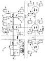
- FIG. 1is a block diagram of a NAN power and data distribution system
- FIG. 2is a block diagram of one embodiment of a distribution box for use with the NAN system of the present invention
- FIG. 3is a schematic diagram of one embodiment of an aerial or pedestal switch assembly for use with the NAN system of the present invention
- FIG. 5is a schematic diagram of the PNET converter of FIG. 4 and further including an amplifier
- FIG. 6is a schematic diagram of one embodiment of a power supply for use with the NAN system of the present invention.
- FIG. 7is a schematic diagram of a power manager for use with the NAN system of the present invention.
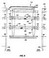
- FIG. 8is a schematic diagram of a dual coaxial cable for use with the NAN system of the present invention.
- FIGS. 1–8wherein like parts are designated by like numerals throughout. It will be readily understood that the components of the present invention, as generally described and illustrated in the figures herein, could be arranged and designed in a wide variety of different configurations. Thus, the following more detailed description of the embodiments of the apparatus, system, and method of the present invention, as represented in FIGS. 1 through 8 , is not intended to limit the scope of the invention, as claimed, but is merely representative of presently preferred embodiments of the invention.
- the NAN 10is configured to distribute both data and power throughout its various segments.
- the NAN 10includes a distribution box 12 which may be in electrical communication with a power drop 14 such as an AC power drop 14 .
- the AC power drop 14may receive metered AC power from an AC power source 16 such as a utility company service line or generator.
- the distribution box 12may further be in electrical communication with an uplink 18 to enable communication with another device or network.
- the uplink 18may be configured to interface with a fiber optic network (not shown).
- the distribution box 12may be configured with switching equipment for communicating between the fiber optic network and the segments of the NAN 10 .
- the distribution box 12is in communication with a coaxial cable 20 A to supply power and data to one or more segments of the NAN 10 .
- the coaxial cable 20 Ais disposed aerially although one of skill in the art will appreciate that the coaxial cable 20 A may be disposed in a variety of environments including being buried or underwater. Aerial disposition is a convenient method to traverse a street or other right-of-way.
- the coaxial cable 20 Ais in communication with an aerial switch 24 A.
- the aerial switch 24 Areceives data and power from the coaxial cable 20 A.
- the aerial switch 24 Atransfers the power and data through a port to another coaxial cable 20 B.
- Additional coaxial cables 20may be included in the NAN 10 , as needed, to complete various segments.
- an aerial switch 24may be in communication with one or more coaxial cables 20 , as needed, by design.
- the aerial switch 24may also be configured to deliver power and data to one or more Cat-5 cables 26 to downlink data to the Cat-5 cable 26 .
- the Cat-5 cable 26may be directed to a respective destination 28 .
- the destination 28may be a residence, office, or other location where data transmission is desired. Destinations 28 are used to house network devices which are configured to interface with a Cat-5 cable 26 .
- additional coaxial cables 20 B, 20 Care in electrical communication with aerial switches 24 B, 24 C.
- Additional aerial switches 24 B, 24 Care incorporated into the NAN 10 as needed to transfer data and power to destinations 28 .
- Each aerial switch 24may be configured to transfer power and data to Cat-5 cables 26 or to other coaxial cables 20 .
- the Cat-5 cables 26provide the transmission segment between the aerial switches 24 and the destinations 28 .
- additional coaxial cables 20 and aerial switches 24may be introduced into the NAN 10 to serve a geographical area.
- the number of aerial switches 24 shown in FIG. 1is for illustrative purposes and the actual number will vary based on the network design.
- Destination 30illustrates equipment which may be placed in communication with the NAN 10 .
- a conventional personal computer 32may be in electrical communication with an interface card 34 .
- the interface card 34is in turn connected to the Cat-5 cable 26 .
- the destination 30generically represents one of various network devices served by the NAN 10 .
- Other network devicesmay include printers, facsimile machines, scanners, terminals, and so forth.
- the Cat-5 cable 26may communicate with these and other network devices.
- the destination 30may also house a plurality of computers 32 , which may communicate with the NAN 10 .
- the destination 30may further house a LAN to interface with the NAN 10 .
- FIG. 1further illustrates buried components and segments of the NAN 10 .
- the distribution box 12 or aerial switch 24may be in communication with a buried coaxial cable 20 to provide a downlink for data and power to other portions of the NAN 10 .
- a buried coaxial cable 20 Dis shown in communication with an aerial switch 24 B and a pedestal mounted switch 36 A.
- a pedestal mounted switch 36is typically configured to provide underground switching and perform similarly to an aerial switch 24 .
- the pedestal mounted switch 36 Amay further be in communication with other pedestal mounted switches 36 B, 36 C through coaxial cables 20 to provide power and data to destinations 28 .
- the pedestal mounted switch 36may provide a downlink for data to destinations 28 through communication with Cat-5 cables 26 .
- the Cat-5 cables 26may be disposed underground and provide the segment between the pedestal mounted switch 36 and the destination 28 .
- switches 24 , 36 and cables 20 , 26may be incorporated into the NAN 10 . All such variations are included within the scope of the present invention.
- a given switch 24 , 36may provide a downlink for as many additional switches 24 , 36 as feasible.
- a switching nodeis a network device having the ability to direct or redirect data and power to an intended destination.
- the switches 24 , 36may be termed switching nodes.
- a segmentis defined herein as a distance traversed by power or data in the NAN 10 .
- a segmentmay be embodied by the coaxial cable 20 or by the Cat-5 cable 26 .
- the suitable number of switches 24 , 36 and ultimate length of segmentsis determined by power supply size, switch power consumption, average network loading per customer, number of customers per distribution segment, and repeater latency for specific applications.
- Power sourcesmay be installed, wherever needed, to supply power to remote locations of the NAN 10 .
- AC powermay be supplied by additional power drops 14 ; or AC power may be distributed by a power bus or extra wires in the coaxial cable 16 .
- the distribution box 12includes a switch 200 which is in communication with the uplink 18 through an uplink port 202 .
- the switch 200further includes one or more downlink ports 204 , which are operably connected to Cat-5 cables 206 to provide downlinks for the power and data.
- the distribution box 12further includes a Power Network (PNET) converter 208 .
- the PNET converter 208converts differential data received from the Cat-5 cable 206 into dual coaxial data suitable for transmission on a dual coaxial cable.
- the PNET converter 208further receives system power from a power control 220 and converts the system power into dual coaxial power.
- the distribution box 12may be configured to serve any reasonable number of distribution segments 210 . As shown in FIG. 2 , the distribution box 12 is operably connected to two (2) distribution segments 210 . One of skill in the art will appreciate that the number of distribution segments 210 may vary depending on the number of downlink ports 204 .
- a distribution segmentmay include a dual coaxial cable 212 , which is operably connected to a corresponding PNET converter 208 to provide the conversion from Cat-5 cable 206 .
- the power for the distribution segments 210may be supplied by any of a variety of methods from the AC power drop 14 .
- the AC power drop 14is in electrical communication with a power conditioner 214 .
- the power conditioner 214is configured to filter out transients, limit current for fault conditions, and supply conditioned AC power to a power transformer 216 .
- the power transformer 216transforms the incoming AC power to 48 VAC and supplies this to a power supply 218 .
- the power supply 218converts the AC voltage to filtered and regulated DC voltage.
- the regulated DC voltageis then passed to the power control 220 .
- the power control 220is configured to supply DC voltage to the PNET converter 208 and to the switch 200 .
- the power control 220may be further configured to run diagnostic operations to monitor power supply over the distribution segments 210 .
- the power control 220may include a network port 222 and a communications controller 224 .
- the network port 222allows for electrical communication of the power control 220 with a Cat-5 cable 226 that is typically in communication with the switch 200 .
- the communications controller 224is typically in communication with the network port 222 to access network administration resources provided by the switch 200 .
- the power control 220provides remote power control to permit cycling of power to network devices within a distribution segment 210 . When network devices become partially or completely disabled by electrostatic energy, lightning, or connection transients, the network devices may be reset by cycling power.
- the distribution box 200may further include a storage battery 228 that contains a reserve of DC voltage.
- the storage battery 228delivers DC voltage to the power supply 218 , as required, in the event of an interruption of power from the AC power drop 14 .
- FIG. 3a block diagram of an aerial switch or pedestal mount switch 24 , 36 is shown and is generally designated as switch assembly 300 .
- the switch assembly 300includes a PNET converter 302 , which is operably connected to an uplink coaxial cable 304 to provide an uplink interface.
- the uplink coaxial cable 304may be considered a component of an uplink segment. As such, the coaxial cable 304 may be operably connected at its opposing end to the distribution box 12 or to another switch assembly 300 .
- the PNET converter 302converts received dual coaxial data to Cat-5 differential data.
- the PNET converter 302is in electrical communication with a switch 306 for transmitting differential data compatible with Cat-5 cables.
- the switch 306is typically configured with sufficient intelligence to enable routing of data packets.
- the switch 306may be configured with a plurality of ports 308 , such as eight (8) ports as shown in FIG. 3 .
- the switch 306may be configured with more than eight (8) ports 308 , but typical installations use an eight (8) port switch 306 for reasons of economy.
- the switch 306is configured to support full duplex 100 Mbps (200 Mbps total) nonblocking internal bus architecture. Although pricing for 100 Mbps technology is presently attractive, evolution to gigabit speeds for cost and performance is anticipated. Additionally, the components described in FIG. 3 may be combined into a single board to eliminate cable connectors, decrease cost, and increase reliability.
- the switch 306may be connected through its ports 308 to one or more Cat-5 cables 309 , which ultimately lead to destinations 28 .
- the Cat-5 cables 309may be considered downlink segments with respect to the switch assembly 300 .
- the switch 306is configured to route data to appropriate destinations based on addresses within the received data packets.
- the switch 306may also be in communication with a second PNET converter 310 , which converts received differential data into coaxial data.
- the PNET converter 310may be operably connected to one or more coaxial cables 312 , 314 which may be considered components of downlink segments.
- the switch assembly 300may further include a power manager 316 configured to enable remote control and remote diagnostics of power distribution to downstream segments of the NAN 10 .
- the PNET converter 302may receive power from the coaxial cable 304 and may transfer the power to the power manager 316 .
- the power manager 316may direct received power into an unmanaged line 320 and a managed line 322 by operation of a switch 324 .
- the switch 324may remain open.
- Powermay be directed to the unmanaged line 320 .
- the power manager 316may include a resetable fuse 326 along the unmanaged line to protect segments of the NAN 10 from power supply shorts.
- Powermay be directed through the unmanaged line 320 to the switch 306 to power the switch 306 .
- the switch 306may direct power to the Cat-5 cables 309 to provide power distribution to the cables 309 .
- the powermay further be directed along the unmanaged line 320 to the PNET converter 310 and to a coaxial cable 312 . This configuration enables powering of the managed switch 306 during cycling of power to the coaxial cable 314 .
- the powermay be directed to managed line 322 by operation of the switch 324 .
- the switch 324When the switch 324 is closed, the power is directed to the PNET converter 310 where it is transmitted to a segment 314 .
- the power managers 316are typically able to delay the powering up of certain segments, such as distant segments.
- the segment 314is a segment to which power may be delayed by operation of the switch 324 .
- closer switches 300may be powered up without the loading effect of the more remote switches 300 .
- the power manager 316automatically connects power through switch 324 to the more remote set of switches 300 . Permitting network control and diagnostics of remote segments also enables faults to be remotely located and, if possible, remotely reset.
- the ratio of power managers 316 to regular switches 300may be only 1 to 10. Thus, not all switches 300 need include a power manager 316 . In embodiments where a power manager 316 is not included, the power is obviously not directed to managed and unmanaged lines and is, instead, passed directly to downlink segments.
- the switch assembly 300may further include a pingable network node 328 for data system fault detection. The node 328 may be in electrical communication with the switch 306 and the power manager 316 to direct pings to the power manager 316 .
- FIG. 4a schematic diagram of one embodiment of a PNET converter 400 is shown.
- the PNET converter 400typically operates in both downlink mode and uplink mode. In the downlink mode, the PNET converter 400 converts differential data to coaxial data.
- the PNET converter 400receives differential data and system power from a Cat-5 cable through downlink port 402 .
- a pair of lines 404 , 406are typically placed in electrical communication with a twisted pair of Cat-5 cable for receiving differential data.
- the lines 404 , 406are in electrical communication with a transformer 408 that is configured to convert differential data to coaxial data.
- a transformer 408may be a Halo TG22-S012.
- the transformer 408 of the depicted embodimentis capable of receiving or transmitting IEEE 802.3u data and converting it to single ended 50 ohm impedance coaxial cable data, a medium that is not specified in the 802.3u specification.
- the transformer 408may be in electrical communication with a line 410 , which may couple to a DC blocking capacitor 412 that may be approximately 0.01 uF.
- the blocking capacitor 412permits transference of data packets, while restricting DC power and attendant 20 power supply noise.
- the line 410continues after the blocking capacitor 412 to a downlink coaxial port 414 .
- the downlink coaxial port 414is typically configured to couple to a dual coaxial cable 416 to transmit coaxial data. More specifically, the downlink coaxial port 414 couples to a conductor 418 in a single coaxial cable 420 in the dual coaxial cable 416 .
- the downlink coaxial port 414may couple to the conductor 418 through a connector 422 , such as a TNC connector.
- an additional line 424is also in communication with the transformer 408 and the downlink coaxial port 414 .
- the line 424is typically placed in communication with a coaxial shield 426 of the single coaxial cable 420 through the downlink coaxial port 414 and the connector 422 .
- the line 424is able to transmit system power as it does not have a blocking capacitor.
- the PNET converter 400further includes an uplink port 428 for communication with a Cat-5 cable.
- a pair or lines 430 , 432may be in electrical communication with a twisted pair of a Cat-5 cable for transmitting differential data.
- the lines 430 , 432are in electrical communication with a transformer 434 that is configured to convert coaxial data to differential data.
- the transformer 434may be one section of a Halo TG22-S012.
- the transformer 434may be in electrical communication with a line 436 that couples to a DC blocking capacitor 438 that may be approximately 0.01 uF.
- the blocking capacitor 438 of the depicted embodimentpasses data packets and restricts DC power and attendant power supply noise.
- the line 436continues after the blocking capacitor 438 to an uplink coaxial port 440 .
- the uplink coaxial port 440is typically configured to couple to a conductor 442 of a single coaxial cable 444 of the dual coaxial cable 416 .
- the uplink coaxial port 440may couple to the single coaxial cable 444 through a connector 446 , such as a TNC connector.
- an additional line 448is also in communication with the transformer 434 and the downlink coaxial port 440 .
- the line 448 of the depicted embodimentis placed in communication with a coaxial shield 450 of the single coaxial cable 444 through the downlink coaxial port 440 and the connector 446 .
- the line 448is able to transmit system power as it does not have a blocking capacitor.
- the dual coaxial cable 416is configured to transmit coaxial data, in full duplex, through the conductors 418 , 442 and to transmit system power through the coaxial shields 426 , 450 .
- the system powermay be DC power.
- One coaxial shield, such as shield 450may be designated as the positive polarity and the other coaxial shield, such as shield 426 , may be designated as the negative polarity.
- the coaxial shields 426 , 450may be embodied as braided copper.
- the DC resistance of the braided copper shields 426 , 450is an order of magnitude less than for 24 gauge Cat-5 wire.
- a 60 VDC (100 W) distribution voltagecan provide power for a 20 switch segment distributed over 4,000 feet of coaxial cable.
- a further advantage of coaxial shields for power distributionis that they reduce noise input into the conductors 418 , 442 and thereby improve signal to noise ratios for data transmission.
- the capability of providing 4,000 foot long NAN distribution segmentspermits convenient and economical installation of distribution boxes at central locations for connection to AC line power taps as well as uplinks to NAN servers.
- the line 448may serve as the positive polarity for system power and the line 424 may serve as the negative polarity.
- Line 448may be in communication with line 452 to direct system power to a filtering capacitor 454 and a transient voltage suppressor 456 that are parallel to one another.
- the filter capacitor 454filters system power and the transient voltage suppressor 456 conditions the system power for transients.
- the PNET converter 400may further include an additional filtering capacitor 458 to filter system power.
- the filtering capacitor 458may be disposed between lines 448 , 424 .
- the line 424may be in electrical communication with line 460 , which is also in communication with the filtering capacitor 454 and the transient voltage suppressor 456 .
- the line 460may further be in communication with a control capacitor 462 parallel to a resistor 464 .
- the control capacitor 462 and the resistor 464provide a controlled path from negative polarity or ground to earth ground 466 .
- a ground connector 468may be coupled to earth ground 466 .
- the ground connector 468may be placed in electrical communication with a ground wire 470 in the coaxial cable 416 .
- the ground wire 470may be in communication with a shield 472 in the coaxial cable 416 to ground the shield 472 .
- the shield 472surrounds both single coaxial cables 420 , 444 for additional protection.
- the PNET converter 400may further include a resettable fuse 474 , such as a positive temperature coefficient thermistor (PTC), in communication with line 452 .
- a resettable fuse 474such as a positive temperature coefficient thermistor (PTC)
- PTCpositive temperature coefficient thermistor
- the resettable fuse 474 of the depicted embodimentprovides fuse protection for faults such as shorts to protect other power segments or branches from shorts. When the system power is turned off, the resettable fuse 474 cools down and is reset. If the short remains upon power reset, then the resettable fuse 474 trips again thereby preventing the shorted segment from killing power to the rest of the NAN 10 .
- the PNET converter 400may further include a fused power connector 476 in electrical communication with the resettable fuse 420 and the filter capacitor 454 and the transient voltage suppressor 456 .
- the fused power connector 476may be configured to provide system power to other segments of the NAN 10 .
- the PNET converter 400may further include another power connector 478 that may not be protected by a resettable fuse 474 .
- the power connector 478may be in communication with the filtering capacitor 454 and the transient voltage suppressor 456 .
- the power connector 478typically provides system power to certain devices such as the switch 306 in the switch assembly 300 . In the embodiment of FIG. 3 , the system power may be first directed through a power manager 316 before it is received in the switch 306 .
- the PNET converter 400may further include an auxiliary power connector 480 configured to receive DC or AC auxiliary power.
- the auxiliary power connector 480is typically in electrical communication with a power port 482 .
- the power port 482is typically configured to enable electrical communication with auxiliary power wires 484 in the coaxial cable 416 .
- DC or AC powermay be transmitted from a distribution box 12 or switch assembly 300 to another network device through the coaxial cable 416 .
- the auxiliary power wires 484permit a remote power box to be powered from a more conveniently located distribution box 12 .
- the PNET converter 400may further include additional lines 486 , 488 that are in communication with the downlink port 402 .
- the lines 486 , 488are typically in electrical communication with lines 430 , 432 respectively.
- the lines 486 , 488may be placed in communication with a twisted pair of Cat-5 cable through the downlink port 402 .
- the lines 486 , 488may serve to upload differential data.
- the PNET converter 400may further include additional lines 490 , 492 that are in communication with the uplink port 428 and lines 404 , 406 respectively.
- the lines 490 , 492may be placed in communication with a twisted pair of Cat-5 cable through the uplink port 428 .
- the lines 490 , 492may be used to download differential data to lines 404 , 406 for conversion to coaxial data and transmission to coaxial cable 416 .
- the additional lines 486 , 488 , 490 , 492serve as crossover connections to permit full duplex data communication through either downlink port 402 or uplink port 428 for further downloading and uploading and are together an optional feature of the present invention.
- the PNET converter 400 of FIG. 4is one embodiment for converting differential data to coaxial data and back again.
- the PNET converter 400is further capable of receiving system power from Cat-5 cable or coaxial cable and distributing the power over other segments of the NAN 10 .
- One of skill in the artwill appreciate that the PNET converter 400 may be embodied in alternative ways and the embodiment of FIG. 4 is for illustrative purposes only. For example, methods for blocking and filtering system power may be achieved with or without the use of blocking or filtering capacitors. Other configurations for external connection of system power may also vary and would be included within the scope of the invention.
- the PNET converter 400further includes an amplifier 500 in electrical communication with the transformer and the downlink coaxial port connector 414 .
- the amplifier 500may be a wideband linear amplifier with 50 ohm output impedance for driving a 50 ohm coaxial cable 414 .
- the gain of the amplifier 500may be set by gain resistors 502 and 503 and is flat out to 100 MHZ. The gain compensates for attenuation in longer lengths of coaxial cable 414 and provides for extended cable lengths.
- Gain resistors 502 and 503may also be replaced with a pre-emphasis network that boosts gain at higher frequencies where cable attenuation is greater.
- the power supply 218may be in electrical communication with the power transformer 216 through an electrical connector, such as a jumper 600 .
- AC power from the power transformer 216passes to the jumper 600 and is fused by a resettable fuse 602 .
- the powermay then be rectified by a rectifier 604 and filtered by capacitors 606 , 608 , 610 , 611 , diode 612 , and resistors 614 , 616 .
- the poweris typically then steered by rectifier 618 and switched by relay 620 to power output connector 622 .
- the relay 620may be controlled by a latched microcontroller port pin that is in communication with a connector 624 .
- a control signal received from the connector 624passes through a resistor 626 and is inverted by transistor 628 and biasing resistors 630 , 632 .
- the inverted control signalthen drives relay control transistor 634 .
- the capacitor 636 and the resistor 638provide a short time delay for turn on and off while switch 640 permits manual reset of the power output connector 622 by service personnel.
- the power supply 218is typically further in communication with a storage battery 228 through a connector 642 .
- the storage battery 228 of the depicted embodimentprovides backup power to run the distribution segment for hours in the event of a power line failure.
- Components 644 , 646 , 648 , 650 , 652 , 654form a charging circuit to charge the storage battery 228 during receipt of AC power.
- Diode 646typically steers current from the storage battery 228 and an unmanaged load connector 656 to the power supply 218 during power outages.
- Resistor 658 of the depicted embodimentprovides a “crowbar” short on the power output connector 622 to discharge switch power supplies more quickly during a power reset cycle.
- the power supply 218 shown in FIG. 6is for illustrative purposes only and the invention is not limited to this embodiment exclusively. Rather, the invention may be implemented through various embodiments of power supplies.
- the power manager 316may include a circuit relay 700 with a crow bar resistor 702 for increasing the reset speed of switches and other loads in communication with the connector 704 on the downlink side of the power distribution system.
- the relay 700is controlled by logic signals received through connector 706 and the time constants of capacitor 708 and resistor 710 .
- the time constantis set for 3–6 seconds to permit loads on the uplink side of connector 712 of the power manager 316 to come up to voltage before the managed segment connector 714 is permitted to be powered up.
- the power manager 316may further include capacitors 716 , 718 , 720 , 722 that store charge during uplink power up. When relay 700 is closed, the charge of capacitors 716 , 718 , 720 , 722 helps boost the power up speed of the downlink loads.
- FIG. 8a schematic diagram of one embodiment of a dual coaxial cable 416 suitable for a NAN 10 of FIG. 1 is shown.
- a practical NANmust employ economical, as well as, hardy/reliable signal and power distribution cable.
- the instant inventionexceeds these requirements with a dual coaxial cable 416 with extra shielding and outdoor sheath.
- the overall cable 416may be covered with a cable shield 472 for EMI and electrostatic discharge protection.
- the cable 416may further include a heavy outer sheath 800 surrounding the cable shield 472 .
- the cable 416may further include auxiliary wires 484 to permit transmission of power to remote network power supplies and devices.
- the single coaxial cables 420 , 444may be configured with a low loss dielectric 802 around center conductors 418 , 442 to extend signal transmission range. Additionally, the single coaxial cables 420 , 444 include coaxial shields 426 , 450 having a heavy gauge braid for conducting system power and for greater hardiness. The single coaxial cables 420 , 444 may each be contained within insulating sheaths 804 , 806 that may be thicker than conventional sheathes to increase robustness. The single coaxial cables 420 , 444 may be in communication with TNC connectors 446 to increase reliability and connection to coaxial ports 414 , 440 .
- the dual coaxial cableis among the hardiest of outdoor network cable technologies.
- the heavy outer sheath 800enables the cable 416 , alternatively, to be sown underground with a vibratory plow or attached to aerial wiring systems.
- Buried dual coaxial cablesare very resistant to garden shovel damage.
- Aerial mount dual coaxial cablesare resistant to weather.
- Coaxial cable faultsare easily diagnosed and repaired with field replaceable splices. Additionally, for a nominal cost, additional 16–18 gauge wires may be added to the dual sheath cable to provide additional signaling and power wires.
- coaxial cablesare much easier and economical to splice in the field for installation and maintenance.
- the present inventionprovides a dual coaxial data and DC power transmission system that exceeds transmission distances found with conventional Cat-5 cable. Since the 802.3u specification is not usable for the coaxial media, the present invention provides a PNET converter 400 for converting 100BaseT differential Cat-5 (100 ohm impedance signals) to single ended coaxial (50 ohm impedance) signals and back again.
- the PNET converter 400may further include an amplifier 500 for boosting data signal levels from a switch output into the coaxial cable. The boosting overcomes the attenuation caused by longer transmission distances.
- the present inventionintegrates power distribution throughout the coaxial cables of a NAN 10 to remote sites. Power distribution in this fashion is necessary because it is not acceptable to power network switches and hubs from a customer's premises power. Furthermore, it is economically prohibitive to employ 50 Amp power drops from utility power lines everywhere network device power is required.
- the shield of one coaxial cablemay be the positive polarity and the shield of a second coaxial cable may be the negative polarity of the NAN power system. Due to the relatively low resistance of shielding and by use of high voltage switching regulators, system power may be distributed over a 4,000 foot segment of coaxial cable. Power distribution in the shields further reduces noise input into the center conductor and improves signal to noise ratios for data transmission.
- the capability of providing 4,000 foot long NAN distribution segmentspermits convenient and economical installation of distribution boxes at central locations for connection to AC line power taps as well as uplinks to the NAN servers.
- the present inventionprovides a system to integrate power and data into a NAN.
- the present inventionextends the distance of individual data segments between switches, pedestals and aerial boxes beyond the industry-specified maximums.
- the NAN system of the present inventionextends the range for power distribution such that the NAN system requires at least ten times fewer power taps from power utilities than required by the industry-specified standards.
- the NAN systemprovides increased reliability and economy of data and power distribution cables.
- the NAN systemfurther converts Cat-5 differential data signals to single ended coaxial cable signals to thereby extend range and to reap the benefits of hardy coaxial cable reliability.
Landscapes
- Engineering & Computer Science (AREA)
- Power Engineering (AREA)
- Computer Networks & Wireless Communication (AREA)
- Signal Processing (AREA)
- Cable Transmission Systems, Equalization Of Radio And Reduction Of Echo (AREA)
Abstract
Description
Claims (50)
Priority Applications (2)
| Application Number | Priority Date | Filing Date | Title |
|---|---|---|---|
| US09/753,747US7072407B2 (en) | 2000-01-31 | 2000-12-27 | Combination power and full duplex data cable |
| PCT/US2001/004060WO2002052745A1 (en) | 2000-12-27 | 2001-02-08 | Combination power and full duplex data cable |
Applications Claiming Priority (2)
| Application Number | Priority Date | Filing Date | Title |
|---|---|---|---|
| US17906000P | 2000-01-31 | 2000-01-31 | |
| US09/753,747US7072407B2 (en) | 2000-01-31 | 2000-12-27 | Combination power and full duplex data cable |
Publications (2)
| Publication Number | Publication Date |
|---|---|
| US20020037054A1 US20020037054A1 (en) | 2002-03-28 |
| US7072407B2true US7072407B2 (en) | 2006-07-04 |
Family
ID=25031973
Family Applications (1)
| Application Number | Title | Priority Date | Filing Date |
|---|---|---|---|
| US09/753,747Expired - LifetimeUS7072407B2 (en) | 2000-01-31 | 2000-12-27 | Combination power and full duplex data cable |
Country Status (2)
| Country | Link |
|---|---|
| US (1) | US7072407B2 (en) |
| WO (1) | WO2002052745A1 (en) |
Cited By (15)
| Publication number | Priority date | Publication date | Assignee | Title |
|---|---|---|---|---|
| US20040153848A1 (en)* | 2002-12-17 | 2004-08-05 | International Business Machines Corporation | Dynamic cable assignment on gigabit infrastructure |
| US20060276073A1 (en)* | 2005-04-07 | 2006-12-07 | Mcmurray William J | Accelerator |
| US20080030201A1 (en)* | 2004-05-13 | 2008-02-07 | Koninklijke Philips Electronics N.V., A Corporation | Method Of Operating A Shielded Connection, And Communication Network |
| US20110119507A1 (en)* | 2007-07-06 | 2011-05-19 | Eaton Industries Gmbh | System and method for controlling bus-networked devices via an open field bus |
| US8045565B1 (en) | 2001-11-20 | 2011-10-25 | Brookline Flolmstead Llc | Method and apparatus for an environmentally hardened ethernet network system |
| USRE43163E1 (en) | 1999-05-14 | 2012-02-07 | Brookline Flolmstead Llc | High-speed network of independently linked nodes |
| US9069519B1 (en) | 2013-12-31 | 2015-06-30 | Ultravision Technologies, Llc | Power and control system for modular multi-panel display system |
| US9164722B2 (en) | 2013-12-31 | 2015-10-20 | Ultravision Technologies, Llc | Modular display panels with different pitches |
| US20150321627A1 (en)* | 2011-12-06 | 2015-11-12 | Continental Automotive Gmbh | Network component for a vehicle network and corresponding vehicle network |
| US9207904B2 (en) | 2013-12-31 | 2015-12-08 | Ultravision Technologies, Llc | Multi-panel display with hot swappable display panels and methods of servicing thereof |
| CN105393465A (en)* | 2013-07-26 | 2016-03-09 | 皇家飞利浦有限公司 | Picking-up signals in electrically contactless manners |
| US9311847B2 (en) | 2014-07-16 | 2016-04-12 | Ultravision Technologies, Llc | Display system having monitoring circuit and methods thereof |
| US9416551B2 (en) | 2013-12-31 | 2016-08-16 | Ultravision Technologies, Llc | Preassembled display systems and methods of installation thereof |
| US10061553B2 (en) | 2013-12-31 | 2018-08-28 | Ultravision Technologies, Llc | Power and data communication arrangement between panels |
| US10659170B2 (en)* | 2017-12-14 | 2020-05-19 | Technetix B.V. | Electrical tap |
Families Citing this family (40)
| Publication number | Priority date | Publication date | Assignee | Title |
|---|---|---|---|---|
| GB2375466A (en)* | 2001-05-09 | 2002-11-13 | Ian Paul Rees | System for connecting viewing stations |
| DE10324373A1 (en)* | 2003-05-28 | 2004-12-23 | Siemens Ag | Power supply via data lines in local networks |
| US6906618B2 (en)* | 2003-06-26 | 2005-06-14 | Abet Technologies, Llc | Method and system for bidirectional data and power transmission |
| US6998538B1 (en)* | 2004-07-30 | 2006-02-14 | Ulectra Corporation | Integrated power and data insulated electrical cable having a metallic outer jacket |
| US7208684B2 (en)* | 2004-07-30 | 2007-04-24 | Ulectra Corporation | Insulated, high voltage power cable for use with low power signal conductors in conduit |
| US20060046766A1 (en)* | 2004-09-01 | 2006-03-02 | Abet Technologies, Llc | Method and system for bidirectional communications and power transmission |
| US8638216B2 (en) | 2004-09-17 | 2014-01-28 | Keith Lamon | Systems and methods for direct current system digital carried message conveyance |
| US7859397B2 (en) | 2004-09-17 | 2010-12-28 | Keith Lamon | Systems and methods for direct current system digital carried message conveyance |
| US7307520B2 (en) | 2004-09-17 | 2007-12-11 | Keith Lamon | Systems and methods for direct current system digital carried message conveyance |
| US7405652B2 (en)* | 2004-09-21 | 2008-07-29 | Abet Technologies, Llc | Communication and AC power system |
| US8587825B2 (en)* | 2005-01-20 | 2013-11-19 | Zih Corp | Ethernet and USB powered printers and methods for supplying ethernet and USB power to a printer |
| JP2008537193A (en)* | 2005-01-31 | 2008-09-11 | アベット テクノロジーズ,エルエルシー | Secure computer system |
| US8214061B2 (en) | 2006-05-26 | 2012-07-03 | Abl Ip Holding Llc | Distributed intelligence automated lighting systems and methods |
| US7848770B2 (en)* | 2006-08-29 | 2010-12-07 | Lgc Wireless, Inc. | Distributed antenna communications system and methods of implementing thereof |
| US7817958B2 (en) | 2006-12-22 | 2010-10-19 | Lgc Wireless Inc. | System for and method of providing remote coverage area for wireless communications |
| US8005050B2 (en)* | 2007-03-23 | 2011-08-23 | Lgc Wireless, Inc. | Localization of a mobile device in distributed antenna communications system |
| US8010116B2 (en) | 2007-06-26 | 2011-08-30 | Lgc Wireless, Inc. | Distributed antenna communications system |
| US9112547B2 (en)* | 2007-08-31 | 2015-08-18 | Adc Telecommunications, Inc. | System for and method of configuring distributed antenna communications system |
| US8311085B2 (en) | 2009-04-14 | 2012-11-13 | Clear-Com Llc | Digital intercom network over DC-powered microphone cable |
| WO2011009135A2 (en)* | 2009-07-17 | 2011-01-20 | Samac Robert A | Automated, adjustable, machine-tool work-piece-mounting apparatus |
| US20140218535A1 (en) | 2011-09-21 | 2014-08-07 | Magna Electronics Inc. | Vehicle vision system using image data transmission and power supply via a coaxial cable |
| US10099614B2 (en) | 2011-11-28 | 2018-10-16 | Magna Electronics Inc. | Vision system for vehicle |
| US10089537B2 (en) | 2012-05-18 | 2018-10-02 | Magna Electronics Inc. | Vehicle vision system with front and rear camera integration |
| US9639906B2 (en) | 2013-03-12 | 2017-05-02 | Hm Electronics, Inc. | System and method for wideband audio communication with a quick service restaurant drive-through intercom |
| US10567705B2 (en) | 2013-06-10 | 2020-02-18 | Magna Electronics Inc. | Coaxial cable with bidirectional data transmission |
| EP2833591A1 (en) | 2013-07-31 | 2015-02-04 | Siemens Aktiengesellschaft | Subsea data communication interface unit |
| ES2686933T3 (en)* | 2013-09-30 | 2018-10-22 | Moog Unna Gmbh | Conversion system, tilt system with a conversion system, and method to operate a conversion system |
| US9473205B2 (en)* | 2014-05-01 | 2016-10-18 | Microchip Technology Incorporated | Coaxial data communication with reduced EMI |
| US9866270B2 (en) | 2014-05-01 | 2018-01-09 | Microchip Technology Incorporated | Coaxial data communication with reduced EMI |
| US10348418B1 (en) | 2014-07-22 | 2019-07-09 | Esker Technologies, LLC | Transient and spurious signal filter |
| US10417143B2 (en) | 2015-10-08 | 2019-09-17 | Esker Technologies, LLC | Apparatus and method for sending power over synchronous serial communication wiring |
| US11285878B2 (en) | 2015-12-17 | 2022-03-29 | Magna Electronics Inc. | Vehicle vision system with camera line power filter |
| US10560154B2 (en) | 2016-07-11 | 2020-02-11 | Esker Technologies, LLC | Power line signal coupler |
| US10128906B2 (en) | 2016-07-11 | 2018-11-13 | Esker Technologies, LLC | Power line signal coupler |
| EP3513413B1 (en)* | 2016-09-15 | 2022-11-02 | Commscope Technologies LLC | Power distribution system for remote radiohead installations |
| US10277268B2 (en)* | 2017-06-02 | 2019-04-30 | Psemi Corporation | Method and apparatus for switching of shunt and through switches of a transceiver |
| JP7004209B2 (en)* | 2018-01-10 | 2022-01-21 | 日立金属株式会社 | Differential transmission cable module |
| DE102019118015A1 (en)* | 2019-07-04 | 2021-01-07 | Connaught Electronics Ltd. | A system and method for transmitting power and signals |
| EP4053577A1 (en)* | 2021-03-04 | 2022-09-07 | Koninklijke Philips N.V. | Transmission line with twisted coaxial cables |
| CN114374442B (en)* | 2021-12-31 | 2024-06-18 | 达沃客(珠海)智能科技有限公司 | A bridge-type transmission device for underwater wireless signals |
Citations (48)
| Publication number | Priority date | Publication date | Assignee | Title |
|---|---|---|---|---|
| US3860748A (en) | 1973-06-20 | 1975-01-14 | Jerrold Electronics Corp | Catv primary and auxiliary power distribution apparatus |
| US3987240A (en) | 1974-06-26 | 1976-10-19 | Glentronics/Division Of Sawyer Industries, Inc. | Direct current power system including standby for community antenna television networks |
| US4839531A (en)* | 1987-10-14 | 1989-06-13 | The Boeing Company | Computer network interconnecting apparatus |
| US4897841A (en) | 1989-01-11 | 1990-01-30 | Hughes Lan Systems, Inc. | System and method for bridging local area networks using concurrent broadband channels |
| US4947389A (en) | 1989-06-06 | 1990-08-07 | At&T Bell Laboratories | Multi-channel ring architecture for distributed networks |
| US5033112A (en) | 1987-07-13 | 1991-07-16 | Northern Telecom Limited | Closed loop, programmable power and communication system |
| US5148144A (en) | 1991-03-28 | 1992-09-15 | Echelon Systems Corporation | Data communication network providing power and message information |
| US5202780A (en) | 1989-04-22 | 1993-04-13 | Alcatel N.V. | Optical communication system for the subscriber area |
| US5420858A (en)* | 1993-05-05 | 1995-05-30 | Synoptics Communications, Inc. | Method and apparatus for communications from a non-ATM communication medium to an ATM communication medium |
| US5428806A (en)* | 1993-01-22 | 1995-06-27 | Pocrass; Alan L. | Computer networking system including central chassis with processor and input/output modules, remote transceivers, and communication links between the transceivers and input/output modules |
| US5477091A (en) | 1991-11-27 | 1995-12-19 | Merlin Gerin | High quality electrical power distribution system |
| US5559377A (en) | 1989-04-28 | 1996-09-24 | Abraham; Charles | Transformer coupler for communication over various lines |
| US5572517A (en) | 1995-02-28 | 1996-11-05 | General Instrument Corporation | Configurable hybrid medium access control for cable metropolitan area networks |
| US5600644A (en) | 1995-03-10 | 1997-02-04 | At&T | Method and apparatus for interconnecting LANs |
| US5699276A (en) | 1995-12-15 | 1997-12-16 | Roos; Charles E. | Utility meter providing an interface between a digital network and home electronics |
| US5701120A (en) | 1992-12-13 | 1997-12-23 | Siemens Business Communication Systems, Inc. | Partitioned point-to-point communications networks |
| US5867484A (en) | 1997-01-31 | 1999-02-02 | Intellect Network Technologies | Switchable multi-drop video distribution system |
| US5896385A (en) | 1995-08-09 | 1999-04-20 | U.S. Philips Corporation | Transmission control method between a plurality of stations and corresponding stations and communication systems |
| US5910954A (en)* | 1994-08-01 | 1999-06-08 | 3Com Corporation | Network switch |
| US5920802A (en) | 1997-06-11 | 1999-07-06 | Gte Laboratories Incorporated | System and method to improve power distribution in a coaxial cable amplifier |
| US5926101A (en) | 1995-11-16 | 1999-07-20 | Philips Electronics North America Corporation | Method and apparatus for routing messages in a network of nodes with minimal resources |
| US5950111A (en)* | 1997-09-25 | 1999-09-07 | Lucent Technologies Inc. | Self-terminating coaxial to unshielded twisted-pair cable passive CATV distribution panel |
| US5960411A (en) | 1997-09-12 | 1999-09-28 | Amazon.Com, Inc. | Method and system for placing a purchase order via a communications network |
| US5963556A (en) | 1993-06-23 | 1999-10-05 | Digital Equipment Corporation | Device for partitioning ports of a bridge into groups of different virtual local area networks |
| US5978373A (en) | 1997-07-11 | 1999-11-02 | Ag Communication Systems Corporation | Wide area network system providing secure transmission |
| US5982767A (en) | 1996-05-30 | 1999-11-09 | Mitel Corporation | Merged telephone and data network |
| US5982854A (en) | 1996-02-23 | 1999-11-09 | Alcatel Usa, Inc. | Fiber optic based subscriber terminal |
| US5994998A (en) | 1997-05-29 | 1999-11-30 | 3Com Corporation | Power transfer apparatus for concurrently transmitting data and power over data wires |
| US6009097A (en) | 1997-04-04 | 1999-12-28 | Lucent Technologies Inc. | System for routing packet switched traffic |
| US6016307A (en) | 1996-10-31 | 2000-01-18 | Connect One, Inc. | Multi-protocol telecommunications routing optimization |
| US6023467A (en) | 1997-05-08 | 2000-02-08 | Ericsson, Inc. | Operations and maintenance data flows over a point to multipoint broadband access network |
| US6023734A (en) | 1997-08-29 | 2000-02-08 | International Business Corporation | Establishing direct communications between two hosts without using a high performance LAN connection |
| US6058367A (en) | 1997-06-13 | 2000-05-02 | Tele-Publishing, Inc. | System for matching users based upon responses to sensory stimuli |
| US6079020A (en) | 1998-01-27 | 2000-06-20 | Vpnet Technologies, Inc. | Method and apparatus for managing a virtual private network |
| US6085249A (en) | 1997-10-24 | 2000-07-04 | Pictra, Inc. | Method and apparatuses for transferring data for multiple applications through a single communication link in response to authentication information |
| US6104711A (en) | 1997-03-06 | 2000-08-15 | Bell Atlantic Network Services, Inc. | Enhanced internet domain name server |
| US6104727A (en) | 1995-04-21 | 2000-08-15 | Hybrid Networks, Inc. | Asymmetric communication system with regulated upstream channel |
| US6112251A (en) | 1998-01-13 | 2000-08-29 | Cabletron Systems, Inc. | Virtual local network for sending multicast transmissions to trunk stations |
| US6122740A (en) | 1996-12-19 | 2000-09-19 | Intel Corporation | Method and apparatus for remote network access logging and reporting |
| US6130879A (en) | 1997-09-22 | 2000-10-10 | Integrated Telecom Express | Access and setup process for end-to-end data and analog voice connections |
| US6144399A (en)* | 1999-03-25 | 2000-11-07 | Mediaone Group, Inc. | Passive system used to merge telephone and broadband signals onto one coaxial cable |
| US6144668A (en) | 1997-11-26 | 2000-11-07 | International Business Machines Corporation | Simultaneous cut through and store-and-forward frame support in a network device |
| US6151629A (en) | 1998-03-02 | 2000-11-21 | Compaq Computer Corporation | Triggered remote dial-up for internet access |
| US6169741B1 (en) | 1995-10-12 | 2001-01-02 | 3Com Corporation | Method and apparatus for transparent intermediate system based filtering on a LAN multicast packets |
| US6175569B1 (en) | 1997-11-07 | 2001-01-16 | International Business Machines Corporation | Extending asynchronous transfer mode ATM QoS across local area networks |
| US6249528B1 (en)* | 1998-03-12 | 2001-06-19 | I-Cube, Inc. | Network switch providing per virtual channel queuing for segmentation and reassembly |
| US6667967B1 (en)* | 1999-05-14 | 2003-12-23 | Omninet Capital, Llc | High-speed network of independently linked nodes |
| US6813279B1 (en)* | 1999-12-29 | 2004-11-02 | Intel Corporation | Ethernet to ATM converter |
- 2000
- 2000-12-27USUS09/753,747patent/US7072407B2/ennot_activeExpired - Lifetime
- 2001
- 2001-02-08WOPCT/US2001/004060patent/WO2002052745A1/enactiveApplication Filing
Patent Citations (50)
| Publication number | Priority date | Publication date | Assignee | Title |
|---|---|---|---|---|
| US3860748A (en) | 1973-06-20 | 1975-01-14 | Jerrold Electronics Corp | Catv primary and auxiliary power distribution apparatus |
| US3987240A (en) | 1974-06-26 | 1976-10-19 | Glentronics/Division Of Sawyer Industries, Inc. | Direct current power system including standby for community antenna television networks |
| US5033112A (en) | 1987-07-13 | 1991-07-16 | Northern Telecom Limited | Closed loop, programmable power and communication system |
| US4839531A (en)* | 1987-10-14 | 1989-06-13 | The Boeing Company | Computer network interconnecting apparatus |
| US4897841A (en) | 1989-01-11 | 1990-01-30 | Hughes Lan Systems, Inc. | System and method for bridging local area networks using concurrent broadband channels |
| US5202780A (en) | 1989-04-22 | 1993-04-13 | Alcatel N.V. | Optical communication system for the subscriber area |
| US5559377A (en) | 1989-04-28 | 1996-09-24 | Abraham; Charles | Transformer coupler for communication over various lines |
| US4947389A (en) | 1989-06-06 | 1990-08-07 | At&T Bell Laboratories | Multi-channel ring architecture for distributed networks |
| US5148144A (en) | 1991-03-28 | 1992-09-15 | Echelon Systems Corporation | Data communication network providing power and message information |
| US5477091A (en) | 1991-11-27 | 1995-12-19 | Merlin Gerin | High quality electrical power distribution system |
| US5701120A (en) | 1992-12-13 | 1997-12-23 | Siemens Business Communication Systems, Inc. | Partitioned point-to-point communications networks |
| US5428806A (en)* | 1993-01-22 | 1995-06-27 | Pocrass; Alan L. | Computer networking system including central chassis with processor and input/output modules, remote transceivers, and communication links between the transceivers and input/output modules |
| US5420858A (en)* | 1993-05-05 | 1995-05-30 | Synoptics Communications, Inc. | Method and apparatus for communications from a non-ATM communication medium to an ATM communication medium |
| US5963556A (en) | 1993-06-23 | 1999-10-05 | Digital Equipment Corporation | Device for partitioning ports of a bridge into groups of different virtual local area networks |
| US5910954A (en)* | 1994-08-01 | 1999-06-08 | 3Com Corporation | Network switch |
| US5572517A (en) | 1995-02-28 | 1996-11-05 | General Instrument Corporation | Configurable hybrid medium access control for cable metropolitan area networks |
| US5847751A (en) | 1995-02-28 | 1998-12-08 | General Instrument Corporation | CATV communication system remote hub for distribution of digital, analog, broadcast and interactive communications |
| US5600644A (en) | 1995-03-10 | 1997-02-04 | At&T | Method and apparatus for interconnecting LANs |
| US6104727A (en) | 1995-04-21 | 2000-08-15 | Hybrid Networks, Inc. | Asymmetric communication system with regulated upstream channel |
| US5896385A (en) | 1995-08-09 | 1999-04-20 | U.S. Philips Corporation | Transmission control method between a plurality of stations and corresponding stations and communication systems |
| US6169741B1 (en) | 1995-10-12 | 2001-01-02 | 3Com Corporation | Method and apparatus for transparent intermediate system based filtering on a LAN multicast packets |
| US5926101A (en) | 1995-11-16 | 1999-07-20 | Philips Electronics North America Corporation | Method and apparatus for routing messages in a network of nodes with minimal resources |
| US5699276A (en) | 1995-12-15 | 1997-12-16 | Roos; Charles E. | Utility meter providing an interface between a digital network and home electronics |
| US5982854A (en) | 1996-02-23 | 1999-11-09 | Alcatel Usa, Inc. | Fiber optic based subscriber terminal |
| US5982767A (en) | 1996-05-30 | 1999-11-09 | Mitel Corporation | Merged telephone and data network |
| US6016307A (en) | 1996-10-31 | 2000-01-18 | Connect One, Inc. | Multi-protocol telecommunications routing optimization |
| US6122740A (en) | 1996-12-19 | 2000-09-19 | Intel Corporation | Method and apparatus for remote network access logging and reporting |
| US5867484A (en) | 1997-01-31 | 1999-02-02 | Intellect Network Technologies | Switchable multi-drop video distribution system |
| US6104711A (en) | 1997-03-06 | 2000-08-15 | Bell Atlantic Network Services, Inc. | Enhanced internet domain name server |
| US6009097A (en) | 1997-04-04 | 1999-12-28 | Lucent Technologies Inc. | System for routing packet switched traffic |
| US6023467A (en) | 1997-05-08 | 2000-02-08 | Ericsson, Inc. | Operations and maintenance data flows over a point to multipoint broadband access network |
| US5994998A (en) | 1997-05-29 | 1999-11-30 | 3Com Corporation | Power transfer apparatus for concurrently transmitting data and power over data wires |
| US6140911A (en) | 1997-05-29 | 2000-10-31 | 3Com Corporation | Power transfer apparatus for concurrently transmitting data and power over data wires |
| US5920802A (en) | 1997-06-11 | 1999-07-06 | Gte Laboratories Incorporated | System and method to improve power distribution in a coaxial cable amplifier |
| US6058367A (en) | 1997-06-13 | 2000-05-02 | Tele-Publishing, Inc. | System for matching users based upon responses to sensory stimuli |
| US5978373A (en) | 1997-07-11 | 1999-11-02 | Ag Communication Systems Corporation | Wide area network system providing secure transmission |
| US6023734A (en) | 1997-08-29 | 2000-02-08 | International Business Corporation | Establishing direct communications between two hosts without using a high performance LAN connection |
| US5960411A (en) | 1997-09-12 | 1999-09-28 | Amazon.Com, Inc. | Method and system for placing a purchase order via a communications network |
| US6130879A (en) | 1997-09-22 | 2000-10-10 | Integrated Telecom Express | Access and setup process for end-to-end data and analog voice connections |
| US5950111A (en)* | 1997-09-25 | 1999-09-07 | Lucent Technologies Inc. | Self-terminating coaxial to unshielded twisted-pair cable passive CATV distribution panel |
| US6085249A (en) | 1997-10-24 | 2000-07-04 | Pictra, Inc. | Method and apparatuses for transferring data for multiple applications through a single communication link in response to authentication information |
| US6175569B1 (en) | 1997-11-07 | 2001-01-16 | International Business Machines Corporation | Extending asynchronous transfer mode ATM QoS across local area networks |
| US6144668A (en) | 1997-11-26 | 2000-11-07 | International Business Machines Corporation | Simultaneous cut through and store-and-forward frame support in a network device |
| US6112251A (en) | 1998-01-13 | 2000-08-29 | Cabletron Systems, Inc. | Virtual local network for sending multicast transmissions to trunk stations |
| US6079020A (en) | 1998-01-27 | 2000-06-20 | Vpnet Technologies, Inc. | Method and apparatus for managing a virtual private network |
| US6151629A (en) | 1998-03-02 | 2000-11-21 | Compaq Computer Corporation | Triggered remote dial-up for internet access |
| US6249528B1 (en)* | 1998-03-12 | 2001-06-19 | I-Cube, Inc. | Network switch providing per virtual channel queuing for segmentation and reassembly |
| US6144399A (en)* | 1999-03-25 | 2000-11-07 | Mediaone Group, Inc. | Passive system used to merge telephone and broadband signals onto one coaxial cable |
| US6667967B1 (en)* | 1999-05-14 | 2003-12-23 | Omninet Capital, Llc | High-speed network of independently linked nodes |
| US6813279B1 (en)* | 1999-12-29 | 2004-11-02 | Intel Corporation | Ethernet to ATM converter |
Cited By (47)
| Publication number | Priority date | Publication date | Assignee | Title |
|---|---|---|---|---|
| USRE43163E1 (en) | 1999-05-14 | 2012-02-07 | Brookline Flolmstead Llc | High-speed network of independently linked nodes |
| US8045565B1 (en) | 2001-11-20 | 2011-10-25 | Brookline Flolmstead Llc | Method and apparatus for an environmentally hardened ethernet network system |
| US7535830B2 (en)* | 2002-12-17 | 2009-05-19 | International Business Machines Corporation | Dynamic cable assignment on gigabit infrastructure |
| US20040153848A1 (en)* | 2002-12-17 | 2004-08-05 | International Business Machines Corporation | Dynamic cable assignment on gigabit infrastructure |
| US20080030201A1 (en)* | 2004-05-13 | 2008-02-07 | Koninklijke Philips Electronics N.V., A Corporation | Method Of Operating A Shielded Connection, And Communication Network |
| US7482815B2 (en)* | 2004-05-13 | 2009-01-27 | Nxp B.V. | Method of operating a shielded connection, and communication network |
| US20060276073A1 (en)* | 2005-04-07 | 2006-12-07 | Mcmurray William J | Accelerator |
| US8935435B2 (en)* | 2007-07-06 | 2015-01-13 | Eaton Electrical Ip Gmbh & Co. Kg | System and method for controlling bus-networked devices via an open field bus |
| US11182327B2 (en) | 2007-07-06 | 2021-11-23 | Eaton Intelligent Power Limited | System and method for controlling bus-networked devices via an open field bus |
| US10599604B2 (en) | 2007-07-06 | 2020-03-24 | Eaton Intelligent Power Unlimited | System and method for controlling bus-networked devices via an open field bus |
| US9164934B2 (en) | 2007-07-06 | 2015-10-20 | Eaton Electrical Ip Gmbh & Co. Kg | System and method for controlling bus-networked devices via an open field bus |
| US20110119507A1 (en)* | 2007-07-06 | 2011-05-19 | Eaton Industries Gmbh | System and method for controlling bus-networked devices via an open field bus |
| US9533635B2 (en)* | 2011-12-06 | 2017-01-03 | Continental Automotive Gmbh | Network component for a vehicle network and corresponding vehicle network |
| US20150321627A1 (en)* | 2011-12-06 | 2015-11-12 | Continental Automotive Gmbh | Network component for a vehicle network and corresponding vehicle network |
| CN105393465A (en)* | 2013-07-26 | 2016-03-09 | 皇家飞利浦有限公司 | Picking-up signals in electrically contactless manners |
| US9941932B2 (en)* | 2013-07-26 | 2018-04-10 | Philips Lighting Holding B.V. | Picking-up signals in electrically contactless manners |
| US9416551B2 (en) | 2013-12-31 | 2016-08-16 | Ultravision Technologies, Llc | Preassembled display systems and methods of installation thereof |
| US9134773B2 (en) | 2013-12-31 | 2015-09-15 | Ultravision Technologies, Llc | Modular display panel |
| US9207904B2 (en) | 2013-12-31 | 2015-12-08 | Ultravision Technologies, Llc | Multi-panel display with hot swappable display panels and methods of servicing thereof |
| US9069519B1 (en) | 2013-12-31 | 2015-06-30 | Ultravision Technologies, Llc | Power and control system for modular multi-panel display system |
| US9349306B2 (en) | 2013-12-31 | 2016-05-24 | Ultravision Technologies, Llc | Modular display panel |
| US9372659B2 (en) | 2013-12-31 | 2016-06-21 | Ultravision Technologies, Llc | Modular multi-panel display system using integrated data and power cables |
| US9195281B2 (en) | 2013-12-31 | 2015-11-24 | Ultravision Technologies, Llc | System and method for a modular multi-panel display |
| US9513863B2 (en) | 2013-12-31 | 2016-12-06 | Ultravision Technologies, Llc | Modular display panel |
| US9528283B2 (en) | 2013-12-31 | 2016-12-27 | Ultravision Technologies, Llc | Method of performing an installation of a display unit |
| US9164722B2 (en) | 2013-12-31 | 2015-10-20 | Ultravision Technologies, Llc | Modular display panels with different pitches |
| US9535650B2 (en) | 2013-12-31 | 2017-01-03 | Ultravision Technologies, Llc | System for modular multi-panel display wherein each display is sealed to be waterproof and includes array of display elements arranged to form display panel surface |
| US9582237B2 (en) | 2013-12-31 | 2017-02-28 | Ultravision Technologies, Llc | Modular display panels with different pitches |
| US9642272B1 (en) | 2013-12-31 | 2017-05-02 | Ultravision Technologies, Llc | Method for modular multi-panel display wherein each display is sealed to be waterproof and includes array of display elements arranged to form display panel surface |
| US9832897B2 (en) | 2013-12-31 | 2017-11-28 | Ultravision Technologies, Llc | Method of assembling a modular multi-panel display system |
| US9916782B2 (en) | 2013-12-31 | 2018-03-13 | Ultravision Technologies, Llc | Modular display panel |
| US9226413B1 (en) | 2013-12-31 | 2015-12-29 | Ultravision Technologies, Llc | Integrated data and power cord for use with modular display panels |
| US9940856B2 (en) | 2013-12-31 | 2018-04-10 | Ultravision Technologies, Llc | Preassembled display systems and methods of installation thereof |
| US9978294B1 (en) | 2013-12-31 | 2018-05-22 | Ultravision Technologies, Llc | Modular display panel |
| US9984603B1 (en) | 2013-12-31 | 2018-05-29 | Ultravision Technologies, Llc | Modular display panel |
| US9990869B1 (en) | 2013-12-31 | 2018-06-05 | Ultravision Technologies, Llc | Modular display panel |
| US10061553B2 (en) | 2013-12-31 | 2018-08-28 | Ultravision Technologies, Llc | Power and data communication arrangement between panels |
| US10248372B2 (en) | 2013-12-31 | 2019-04-02 | Ultravision Technologies, Llc | Modular display panels |
| US10373535B2 (en) | 2013-12-31 | 2019-08-06 | Ultravision Technologies, Llc | Modular display panel |
| US10380925B2 (en) | 2013-12-31 | 2019-08-13 | Ultravision Technologies, Llc | Modular display panel |
| US10410552B2 (en) | 2013-12-31 | 2019-09-10 | Ultravision Technologies, Llc | Modular display panel |
| US10540917B2 (en) | 2013-12-31 | 2020-01-21 | Ultravision Technologies, Llc | Modular display panel |
| US9081552B1 (en) | 2013-12-31 | 2015-07-14 | Ultravision Technologies, Llc | Integrated data and power cord for use with modular display panels |
| US10871932B2 (en) | 2013-12-31 | 2020-12-22 | Ultravision Technologies, Llc | Modular display panels |
| US10706770B2 (en) | 2014-07-16 | 2020-07-07 | Ultravision Technologies, Llc | Display system having module display panel with circuitry for bidirectional communication |
| US9311847B2 (en) | 2014-07-16 | 2016-04-12 | Ultravision Technologies, Llc | Display system having monitoring circuit and methods thereof |
| US10659170B2 (en)* | 2017-12-14 | 2020-05-19 | Technetix B.V. | Electrical tap |
Also Published As
| Publication number | Publication date |
|---|---|
| WO2002052745A1 (en) | 2002-07-04 |
| US20020037054A1 (en) | 2002-03-28 |
Similar Documents
| Publication | Publication Date | Title |
|---|---|---|
| US7072407B2 (en) | Combination power and full duplex data cable | |
| US7259657B2 (en) | Multi-subnet power line communications system and method | |
| US5864284A (en) | Apparatus for coupling radio-frequency signals to and from a cable of a power distribution network | |
| US7103240B2 (en) | Method and apparatus for providing inductive coupling and decoupling of high-frequency, high-bandwidth data signals directly on and off of a high voltage power line | |
| EP0667067B1 (en) | Transmission network and filter therefor | |
| US7667344B2 (en) | Coupling communications signals to underground power lines | |
| US7187276B2 (en) | Power line communication system and method of using the same | |
| US6348874B1 (en) | Power distribution to nodes in a distributed system | |
| US7218219B2 (en) | Data communication over a power line | |
| US20060255930A1 (en) | Power line communications system and method | |
| US7561026B2 (en) | Bypass device and method for a power line communications system | |
| SE1000953A1 (en) | Signal repeater system arrangement for stable data communication | |
| US20020109585A1 (en) | Apparatus, method and system for range extension of a data communication signal on a high voltage cable | |
| US20010054953A1 (en) | Digital communications utilizing medium voltage power distribution lines | |
| AU2001255401A1 (en) | Digital communications utilizing medium voltage power distribution lines | |
| WO2006047440A2 (en) | Arrangement of inductive couplers for data communication | |
| US8045565B1 (en) | Method and apparatus for an environmentally hardened ethernet network system | |
| US6836898B1 (en) | Subscriber power module for CATV customer interface equipment | |
| EP1259074A1 (en) | Communication system comprising means for preventing intermodulation products |
Legal Events
| Date | Code | Title | Description |
|---|---|---|---|
| AS | Assignment | Owner name:SWITCHPOINT NETWORKS, INC., UTAH Free format text:ASSIGNMENT OF ASSIGNORS INTEREST;ASSIGNOR:SCHURIG, ALMA K.;REEL/FRAME:012082/0434 Effective date:20010727 | |
| AS | Assignment | Owner name:OMNINET CAPITAL LLC, AS AGENT, CALIFORNIA Free format text:SECURITY AGREEMENT;ASSIGNOR:SWITCHPOINT NETWORKS, INC.;REEL/FRAME:013271/0021 Effective date:20020619 | |
| AS | Assignment | Owner name:OMNINET CAPITAL, LLC, CALIFORNIA Free format text:ASSIGNMENT OF ASSIGNORS INTEREST;ASSIGNOR:SWITCHPOINT NETWORKS, INC.;REEL/FRAME:013912/0846 Effective date:20030822 | |
| AS | Assignment | Owner name:OMNINET INVESTMENTS, LLC, CALIFORNIA Free format text:ASSIGNMENT OF ASSIGNORS INTEREST;ASSIGNOR:OMNINET CAPITAL, LLC;REEL/FRAME:015215/0334 Effective date:20041004 | |
| AS | Assignment | Owner name:SWITCHPOINT NETWORKS INC., UTAH Free format text:SECURITY INTEREST RELEASE AND TERMINATION;ASSIGNOR:OMNINET CAPITAL LLC, AS AGENT;REEL/FRAME:015242/0083 Effective date:20041006 | |
| AS | Assignment | Owner name:BROOKLINE FLOLMSTEAD LLC, NEVADA Free format text:ASSIGNMENT OF ASSIGNORS INTEREST;ASSIGNOR:OMNINET INVESTMENTS, LLC;REEL/FRAME:015361/0885 Effective date:20041013 | |
| STCF | Information on status: patent grant | Free format text:PATENTED CASE | |
| CC | Certificate of correction | ||
| CC | Certificate of correction | ||
| CC | Certificate of correction | ||
| FEPP | Fee payment procedure | Free format text:PAYOR NUMBER ASSIGNED (ORIGINAL EVENT CODE: ASPN); ENTITY STATUS OF PATENT OWNER: LARGE ENTITY | |
| FPAY | Fee payment | Year of fee payment:4 | |
| FPAY | Fee payment | Year of fee payment:8 | |
| AS | Assignment | Owner name:RATEZE REMOTE MGMT. L.L.C., DELAWARE Free format text:MERGER;ASSIGNOR:BROOKLINE FLOLMSTED LLC;REEL/FRAME:037253/0659 Effective date:20150826 | |
| MAFP | Maintenance fee payment | Free format text:PAYMENT OF MAINTENANCE FEE, 12TH YEAR, LARGE ENTITY (ORIGINAL EVENT CODE: M1553) Year of fee payment:12 |