US7072341B2 - Real time streaming media communication system - Google Patents
Real time streaming media communication systemDownload PDFInfo
- Publication number
- US7072341B2 US7072341B2US10/077,510US7751002AUS7072341B2US 7072341 B2US7072341 B2US 7072341B2US 7751002 AUS7751002 AUS 7751002AUS 7072341 B2US7072341 B2US 7072341B2
- Authority
- US
- United States
- Prior art keywords
- client
- network address
- caller
- real time
- channel
- Prior art date
- Legal status (The legal status is an assumption and is not a legal conclusion. Google has not performed a legal analysis and makes no representation as to the accuracy of the status listed.)
- Expired - Lifetime, expires
Links
- 238000004891communicationMethods0.000titledescription20
- 230000011664signalingEffects0.000claimsdescription87
- 238000013519translationMethods0.000claimsdescription53
- 230000004044responseEffects0.000claimsdescription44
- 238000000034methodMethods0.000claimsdescription18
- 239000000284extractSubstances0.000abstractdescription7
- 238000010586diagramMethods0.000description9
- 230000000977initiatory effectEffects0.000description9
- 230000005236sound signalEffects0.000description7
- RYGMFSIKBFXOCR-UHFFFAOYSA-NCopperChemical compound[Cu]RYGMFSIKBFXOCR-UHFFFAOYSA-N0.000description5
- 229910052802copperInorganic materials0.000description5
- 239000010949copperSubstances0.000description5
- 230000005540biological transmissionEffects0.000description3
- 238000007906compressionMethods0.000description3
- 230000006835compressionEffects0.000description3
- 230000008878couplingEffects0.000description3
- 238000010168coupling processMethods0.000description3
- 238000005859coupling reactionMethods0.000description3
- 239000000835fiberSubstances0.000description2
- 238000012986modificationMethods0.000description2
- 230000004048modificationEffects0.000description2
- 241000237519BivalviaSpecies0.000description1
- 230000001413cellular effectEffects0.000description1
- 230000008859changeEffects0.000description1
- 235000020639clamNutrition0.000description1
- 238000013144data compressionMethods0.000description1
- 238000005538encapsulationMethods0.000description1
- 230000006870functionEffects0.000description1
- 238000012423maintenanceMethods0.000description1
- 230000000737periodic effectEffects0.000description1
- 230000008569processEffects0.000description1
- 238000010025steamingMethods0.000description1
- 238000012546transferMethods0.000description1
Images


Classifications
- H—ELECTRICITY
- H04—ELECTRIC COMMUNICATION TECHNIQUE
- H04L—TRANSMISSION OF DIGITAL INFORMATION, e.g. TELEGRAPHIC COMMUNICATION
- H04L61/00—Network arrangements, protocols or services for addressing or naming
- H04L61/09—Mapping addresses
- H04L61/25—Mapping addresses of the same type
- H04L61/2503—Translation of Internet protocol [IP] addresses
- H04L61/256—NAT traversal
- H04L61/2564—NAT traversal for a higher-layer protocol, e.g. for session initiation protocol [SIP]
- H—ELECTRICITY
- H04—ELECTRIC COMMUNICATION TECHNIQUE
- H04L—TRANSMISSION OF DIGITAL INFORMATION, e.g. TELEGRAPHIC COMMUNICATION
- H04L61/00—Network arrangements, protocols or services for addressing or naming
- H04L61/09—Mapping addresses
- H04L61/25—Mapping addresses of the same type
- H04L61/2503—Translation of Internet protocol [IP] addresses
- H04L61/256—NAT traversal
- H04L61/2589—NAT traversal over a relay server, e.g. traversal using relay for network address translation [TURN]
- H—ELECTRICITY
- H04—ELECTRIC COMMUNICATION TECHNIQUE
- H04L—TRANSMISSION OF DIGITAL INFORMATION, e.g. TELEGRAPHIC COMMUNICATION
- H04L65/00—Network arrangements, protocols or services for supporting real-time applications in data packet communication
- H04L65/10—Architectures or entities
- H04L65/1045—Proxies, e.g. for session initiation protocol [SIP]
- H—ELECTRICITY
- H04—ELECTRIC COMMUNICATION TECHNIQUE
- H04L—TRANSMISSION OF DIGITAL INFORMATION, e.g. TELEGRAPHIC COMMUNICATION
- H04L65/00—Network arrangements, protocols or services for supporting real-time applications in data packet communication
- H04L65/10—Architectures or entities
- H04L65/1053—IP private branch exchange [PBX] functionality entities or arrangements
Definitions
- the present inventionrelates to communicating media data in a packet switched data network and, more specifically, to establishing and maintaining real time media data sessions through a firewall.
- each telephone handsetis coupled to a local switching station on a dedicated pair of copper wires known as a subscriber loop.
- the circuitis completed by dynamically coupling each subscriber loop to a dedicated pair of copper wires between the two switching stations.
- a computing devicedigitizes the analog signals and formats the digitized data into frames such that multiple conversations can be transmitted simultaneously on the same fiber.
- a computing devicereforms the analog signals for transmission on copper wires. Twisted pair copper wires of the subscriber loop are still used to couple the telephone handset to the local switching station.
- Each end point computerincludes appropriate hardware for driving a microphone and a speaker.
- Each end pointoperates simultaneously both as a sender of real time voice data and as a receiver of real time voice data to support a full duplex voice conversation.
- the end point computerconverts voice signals from analog format, as detected by the microphone, to digital format.
- the softwarethen facilitates data compression down to a rate compatible with the end point computer's data connection to an Internet Service Provider (ISP) and facilitates encapsulation of the digitized and compressed voice data into a frame compatible with the user datagram protocol and internet protocol (UDP/IP) to enable communication to the other end point via the Internet.
- ISPInternet Service Provider
- UDP/IPuser datagram protocol and internet protocol
- the end point computer and softwarereverse the process to recover the analog voice information for presentation to the operator via the speaker associated with the receiving computer.
- the International Telephony Union(ITU) had developed a set of standards for Internet telephony.
- the ITU Q.931 standardrelates to call signaling and set up
- the ITU H.245 standardprovides for negotiation of channel usage and compression capabilities between the two endpoints
- the ITU H.323 standardprovides for real time voice data between the two end points to occur utilizing UDP/IP to deliver the real time voice data.
- SIPSession Initiation Protocol
- NATnetwork address translation
- both the ITU Internet telephony standards and the SIP standardsprovide for each endpoint to designate a real time transport protocol (RTP) channel, which comprises an IP address and port number, for receipt of media datagrams and to provide that RTP channel to the other end point.
- RTPreal time transport protocol
- the private network clientdoes not have a globally unique IP address, a frame sent to such non-globally unique IP address can not be routed on the Internet and will be lost. Further, even if the private network client were able to identify and designate the IP address of the NAT firewall, the private network client has no means for establishing a port on the NAT firewall for receipt of media datagrams.
- NAT firewallswhich typically provide both IP address translation and port translation of all frames sent from the private network to the Internet.
- a system and method for establishing and maintaining Internet telephony conversations between two clientsboth of which are located on private networks behind NAT firewalls.
- an Internet routable IP addresse.g. public IP address on the Internet
- a first aspect of the present inventionis to provide a device for sending datagrams representing real time streaming media frames to a client independent of whether the client is served by a network address proxy.
- the devicecomprises means for receiving a datagram originated by the client that includes an indicated network address and an indicated port number for receipt of the datagrams representing real time streaming media frames, means for extracting a source network address and a source port number from the datagram originated by the client, means for comparing the indicated network address to the source network address.
- the deviceaddresses the datagrams representing real time streaming media frames to the source network address and source port number if the indicated network address and the source network address are not the same. And, the device addresses the datagrams representing real time streaming media frames to the indicated network address and the indicated port number if the indicated network address and the source network address are the same.
- a second aspect of the present inventionit to provide a device for sending datagrams representing real time streaming frames to a client independent of whether the client is served by a network address proxy.
- the devicecomprises means for receiving a datagram originated by the client that includes an indicated network address and an indicated port number for receipt of the datagrams representing real time streaming media frames and means for establishing a destination network address and destination port number for sending the datagrams representing real time streaming media frames to the client.
- the destination network address and destination port numberbeing the indicated network address and the indicated port number respectively if the indicated network address matches a source network address extracted from the datagram.
- the destination network addressbeing a source network address and a source port number extracted from the datagram if the indicated network address does not match the source network address.
- a third aspect of the present inventionis to also provide a device for sending datagrams representing real time streaming frames to a client independent of whether the client is served by a network address proxy.
- the devicecomprises means for receiving a session set up datagram originated by the client that includes an indicated network address and an indicated port number for receipt of the datagrams representing real time streaming media frames, means for receiving a session datagram originated by the client, and means for establishing a destination network address and destination port number for sending the datagrams representing real time streaming media frames to the client.
- the destination network address and destination port numberbeing the indicated network address and the indicated port number respectively if the indicated network address matches a source network address extracted from the session datagram.
- the destination network address and port numberbeing a source network address and a source port number extracted from the datagram if the indicated network address does not match the source network address extracted from the session datagram.
- FIG. 1is a block diagram of a real time media communication network in accordance with one embodiment of this invention
- FIGS. 2 a and 2 bare block diagrams representing call set up messaging in accordance with one embodiment of the present invention.
- FIG. 3 ais a block diagram of a directory server in accordance with one embodiment of the present invention.
- FIG. 3 bis a block diagram of a call control manager in accordance with one embodiment of the present invention.
- FIGS. 4 a and 4 bare flow charts showing exemplary operation of a client registration application in accordance with one embodiment of the present invention.
- FIGS. 5 a and 5 bare flow charts showing exemplary operation of a directory server session set up application in accordance with one embodiment of the present invention
- FIG. 6is a flow chart showing exemplary operation of a call control manager session set up server application in accordance with one embodiment of the present invention
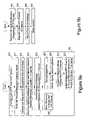
- FIG. 7is a flow chart showing exemplary operation of a session relay server in accordance with one embodiment of the present invention.
- FIG. 8is a block diagram of a real time streaming media client in accordance with one embodiment of the present invention.
- FIGS. 9 a and 9 bare flow charts showing exemplary operation of a client in accordance with one embodiment of the present invention.
- each element with a reference numberis similar to other elements with the same reference number independent of any letter designation following the reference number.
- a reference number with a specific letter designation following the reference numberrefers to the specific element with the number and letter designation and a reference number without a specific letter designation refers to all elements with the same reference number independent of any letter designation following the reference number in the drawings.
- circuitsmay be implemented in a hardware circuit(s), a processor executing software code, or a combination of a hardware circuit(s) and a processor or control block of an integrated circuit executing machine readable code.
- the term circuit, module, server, or other equivalent description of an element as used throughout this specificationis intended to encompass a hardware circuit (whether discrete elements or an integrated circuit block), a processor or control block executing code, or a combination of a hardware circuit(s) and a processor and/or control block executing code.
- the real time media communication network 10includes a network 12 interconnecting a plurality of network devices.
- the network 12may be the Internet.
- the network 12may be referred to as the “Internet”, however, it should be appreciated this is for illustrative purposes only and does not limit the network 12 to the Internet or similar networks.
- Coupled to the Internet 12are a plurality of network devices which for purposes of this invention includes a real time media communication client 14 , network address translation proxy servers 28 and 30 , each operating as a firewall for private networks 24 and 26 respectively, and a telephony service provider 34 that includes a directory server 38 and a call control manager 36 .
- Each of the network devicesoperates a suite of IP protocols that enable the device to set up TCP/IP logical connections and/or UDP/IP channels with other network devices over the Internet 12 .
- Each deviceis assigned a public Internet Protocol (IP) address and IP datagrams are communicated between the various devices utilizing each device's IP network address for routing the datagrams from the source device to the destination device.
- IPInternet Protocol
- Each network address translation proxy 28 and 30may be a network address translation (NAT) server that operates as an IP layer proxy for clients 16 and 18 that are coupled to each of a private networks 24 and 26 respectively.
- NATnetwork address translation
- the network address translation proxy 28 and 30may be referred to as a “NAT Server”, however, it should be appreciated this is for illustrative purposes only and does not limit the structure to that of a traditional NAT server.
- Each private network 24 and 26may function in a similar manner to the Internet 12 using the IP protocols for routing datagrams between the clients 16 and 18 and its respective NAT server 28 and 30 .
- the IP network address assigned to each client 16 or 18 on the private networkmay be an address selected from a class of IP network addresses reserved for private networks and the IP network address assigned to each client 16 or 18 may be the same as the address assigned to another client on another private network.
- Datagrams with an IP address within the private network classare routable on the private network but are not routable on the Internet 12 .
- Datagrams with an IP address that is globally unique (routable on the Internet 12 )are routable on the private network but are always routed to the NAT server 30 or 28 which in turn proxies the datagram on the Internet.
- the NAT server 28 or 30emulates the destination device when opening a connection and communicating datagrams with the initiating device on the private network and operates as an IP layer proxy, by performing both address translation and port translation, to open a connection and exchange data with the destination device, on behalf of the initiating device, over the Internet 12 .
- the NAT server 28 and 30may also be capable of translating connectionless datagrams sent by the initiating device on the private network by performing both address translation, port translation, and sending the connectionless datagrams to the destination device over the Internet 12 . And, if a connectionless datagram were to be replied to by the destination device and the reply datagram is: 1) received at the NAT server on the same port number as the NAT server utilized when translating the connectionless datagram; 2) includes a source network address and port number which matches the destination network address and port number of the connectionless datagram sent by the NAT server; and 3) is received within a predefined time window following when the NAT server sent the connectionless datagram, then the response datagram may be routed back to the initiating device on the private network.
- the NAT servermay maintain a translation table that maps the source address and port number of the initiating device to the corresponding translated source address and port number of the NAT server for each TCP/IP connection opened (and UDP/IP connectionless datagram sent) by NAT server on the Internet.
- the NAT servermay utilize the translation table to relay a reply frame received over the Internet 12 back to the appropriate initiating device by looking up the initiating device network address and port number that is associated with the port number on which the NAT server received the reply datagram on the Internet 12 .
- each entry in the translation tablemay also include the destination network address and port number to which the translated frame was sent over the Internet 12 .
- the NAT servermay verify that a reply frame is truly a reply frame from the device to which the translated frame was sent by comparing the source address and port number of the reply frame to the destination network address and port number to which the translated frame was sent.
- the telephone service provider 34or more specifically the directory server 38 and the call control manager 36 , enable the signaling and maintenance of real time streaming media sessions between a caller client and a callee client, each of which is selected from the group of clients 14 , 16 , and 18 , independent of whether the caller client and/or the callee client is operating on a private network 24 or 26 and served by a NAT server 28 or 30 .
- the directory server 38 and the call control manager 36enable client 14 operating as a caller client to signal a real time streaming media session to either of clients 16 or 18 operating on private networks 24 and 26 respectively and, enable either of clients 16 or 18 operating as a caller client to signal and maintain a real time streaming media session with another of clients 14 , 16 or 18 .
- the directory server 34facilitates signaling a media session. Human operators are accustomed to working with 10-digit telephone numbers which, once assigned to a person, remain relatively stable. However, each client 14 , 16 , and 18 coupled to the Internet 12 or to a private network 24 or 26 is addressed via a 12-digit network address which may change each time the device logs onto a network. Therefore, the directory server 34 maintains a client table database 42 that associates each client 14 , 16 , and 18 to a client identifier that is stable and to a network address currently assigned to the client. As such, the caller client may quarry the directory server 34 identifying a callee client by its stable client identifier to obtain a network address for signaling the callee client.
- Each of NAT server 28 and 30prevents a caller client from directly signaling a callee client 16 or 18 on its private network 24 or 26 because it can only reverse translate a datagram that is a reply to a datagram initiated by a client 16 or 18 respectively.
- a call signaling message to initiate a media sessionis a first message originated by a caller client to initiate a media session and therefore can not be a reply to a message originated by the callee client to the caller client. Therefore, the directory server 34 also maintains an open channel to each client 16 or 18 that is located on a private network.
- the client 16 or 18periodically sends a ping datagram to the directory server 34 such that its NAT server 28 or 30 respectively translates the datagram and writes an applicable entry to its translation table.
- the directory server 34extracts the source network address and source port ID number from each ping datagram. Because the NAT server can reverse translate a datagram sent from the directory server 34 to the extracted source network address and source port number, such extracted source network address and source port number identify the open channel until the next ping datagram from the client is received. Therefore, the directory server 34 may relay a call signaling message form a caller client to a callee client on the open channel even if the callee client is operating on a private network.
- the call control manager 36facilitates communication of real time media data during the session between the caller client and the callee client when both the caller client and the callee client are on a private network 24 or 26 .
- a NAT servercan not reverse translate a datagram unless it is in response to a datagram originated by a client, it is impossible for client 16 on private network 28 to initiate sending datagrams to client 18 because NAT server 30 will not reverse translate and it is impossible for client 18 to initiate sending datagram to client 16 because NAT server 28 will not reverse translate.
- both clients 16 and 18may initiate sending datagrams to the call control manager 36 and the call control manager 36 operates as a relay there between.
- the call control manager 36can extract a source network address and a source port number from datagrams originated by client 18 (and translated by NAT server 30 ) to identify a destination network address and port number to which datagrams can be sent as response datagrams that are reverse translatable by the NAT server 30 .
- the response datagramsinclude the real time steaming media data received from client 16 .
- the call control manager 36can extract a source network address and a source port number from datagrams originated by client 16 (and translated by NAT server 28 ) to identify a destination network address and port number to which datagrams can be sent as response datagrams that are reverse translatable by the NAT server 28 .
- the response datagramsinclude the real time media session data received from client 18 .
- FIG. 2 arepresents signaling a media session and relaying of real time streaming media data between caller client 16 that is served by the NAT server 28 and callee client 18 that is served by the NAT server 30 utilizing the directory server 38 and the call control manager 36 .
- Signal 57represents the caller client 16 originating a call request message to the directory server 38 to obtain a network address for signaling the callee client 18 .
- the call request messagewill identify the callee client by its stable client identifier.
- Signal 59represents the directory server 38 responding to the caller client 16 , on the open channel to the caller client 16 , with a call request acknowledge signal that includes a network address to utilize for signaling the callee client 18 . Because the callee client 18 is on the private network 30 and can not be directly signaled, the network address in the call request acknowledge message will be the network address of the directory server 38 .
- Signal 60represents the caller client 16 originating a media session signaling message to the directory server 38 that includes the session identifier and a real time transport protocol channel (caller client RTP channel) established by the caller client 16 for receipt of media datagrams during the media session.
- Signal 62represents the directory server 38 passing the media session signaling message to the call control manager 36 .
- Signal 64represents the call control manager returning a call signaling message to the directory server 38 that include a real time transport protocol channel established by the call control manager 36 for receipt of media datagrams during the session (CCM RTP channel) substituted for the caller client RTP channel.
- Signal 66represents the directory server sending the call signaling message that was received from the call control manager 26 to the callee client 18 on the open channel to the callee client 18 .
- the caller client RTP channelwill include a network address that is local to private network 24 and is unrouteable on the Internet 12 .
- the CCM RTP channelwill include a network address that is globally unique.
- Signal 68represent the callee client 18 generating a response message back to the directory server 38 that includes a callee client RTP channel that is established by the callee client 18 for receipt of media datagrams during the session. Again, the callee client RTP channel will include a network address that is unrouteable on the Internet 12 .
- Signal 70represents the directory server 38 passing the response message to the call control manager 36 and signal 72 represents the response message back from the call control manager 36 that includes the CCM RTP channel substituted for the callee client RTP channel.
- Signal 74represents the directory server passing the response signal to the caller client on the open channel to the caller client 16 .
- the sessionstarts and the caller client 16 and the callee client 18 each begin sending media session datagrams encapsulating real time streaming media frames to the call control manager 36 on the CCM RTP channel as represented by signals 76 and 80 respectively.
- the call control manager 36extracts the source network address and source port number from datagrams received from each of the caller client 16 and the callee client 18 during the session to determine a destination network address and destination port number to each of the caller client 16 and the callee client 18 .
- the call control manager 36then relays the datagrams received from the caller client 16 to the callee client 18 utilizing the destination network address and destination port number as extracted from datagrams originated by the callee client 18 and relays datagrams received from the callee client 18 to the caller client 16 utilizing the destination network address and destination port number as extracted from datagrams originated by the caller client 16 .
- FIG. 2 brepresents signaling a media session and communication real time streaming media data between a caller client 14 that has a globally unique network address and a callee client 18 served by NAT server 30 .
- Signal 87represents the caller client 14 originating a call request message to the directory server 38 to obtain a network address for signaling the callee client 18 .
- the call request messagewill identify the callee client 18 by its stable client identifier.
- Signal 89represents the directory server 38 responding to the caller client 14 with a call request acknowledge signal that includes a network address to utilize for signaling the callee client 18 . Because the callee client 18 is on the private network 30 and can not be directly signaled, the network address in the call request acknowledge message will be the network address of the directory server 38 .
- Signal 90represents the caller client 14 originating a call signaling message to the directory server 38 that includes the session identifier and a caller RTP channel established by the caller client 14 for receipt of media datagrams during the media session.
- Signal 92represents the directory server 38 passing the call signaling message to the callee client 18 on the open channel to the callee client 18 .
- Signal 94represent the callee client 18 generating a response message back to the directory server 38 that includes a callee RTP channel established by the callee client 18 for receipt of media datagrams during the media session.
- Signal 96represents the directory server 38 passing the response message to the caller client 14 .
- the callee client 18begins originating datagrams encapsulating real time streaming media frames to the caller client 14 on the caller RTP channel as represented by signal 100 .
- the caller client 14extracts the source network address and source port number from datagrams received from the callee client 18 to use as a destination network address and destination port number for sending datagrams to the callee client 18 as represented by signal 98 .
- FIG. 3 ais a block diagram representing an exemplary directory server 38 .
- the directory server 38may be embodied in typical server hardware that includes a processor 20 for operating a client registration server application 40 , a client table database 42 , and a session set up server application 44 as well as operating an IP suite 13 and a network interface circuit 12 for communicating with other devices coupled to the Internet 12 .
- a processor 20for operating a client registration server application 40 , a client table database 42 , and a session set up server application 44 as well as operating an IP suite 13 and a network interface circuit 12 for communicating with other devices coupled to the Internet 12 .
- the structure and functionality of each of the client registration server application 40 , the client table database 42 , and the session set up server application 44may be embodied in a single application or distributed across multiple applications operating on the directory server hardware.
- the client table database 42associated each client, as identified by its unique client identifier 180 , to its current network address 184 and to the current open channel to the client 182 .
- the client table database 42also includes a global/local indicator 186 that indicates whether the current network address 184 is a local network address “L” or a globally unique network address “G”.
- the client registration server application 40operates in accordance with the flowcharts of FIGS. 4 a and 4 b .
- Step 190represents receipt of such a request.
- the requestwill include the client identifier and will include the client's current network address. In the case of client 14 , this will be a globally unique network address and in the case of clients 16 and 18 this will be a local network address that is routable only on the private network 24 and 26 respectively.
- Step 192represents writing the client network address to field 184 in the record associated with the client as identified by the client identifier field 180 .
- Step 194represents extracting the source network address of the UDP/IP or TCP/IP datagram that encapsulated the registration request and determining whether the client network address matches the extracted source network address.
- client 14which is directly coupled to the internet
- the two addresseswill match.
- the two addresseswill not match because the client network address will be the clients local network address while the extracted source network address will be the globally unique network address of the NAT server 28 and 30 respectively.
- step 196represents writing a global indicator “G” to the local/global indicator field 186 in the client table database 42 . If the addresses do not match, step 198 represents writing a local indicator “L” to the local/global indicator field 186 in the client table database 42 .
- step 200represents writing the extracted source network address and an extracted port number to an open channel field 182 in the client table database 42 .
- each NAT server 28 and 30will reverse translate a datagram that is received on the same port number on which a translated datagram was sent.
- the directory server 38may send a datagram to the extracted source address and extracted source port number and the NAT server will reverse translate the datagram and send it to the client on the private network.
- Step 206represents assigning a keep alive ping interval to the client.
- the NAT serverwill only reverse translate datagrams that are received within brief time window following the sending of the translated frame.
- the purpose of the ping intervalis to set a time interval for the client to continually ping the directory server 38 so that the reverse channel through the NAT server remains open.
- the Flowchart of FIG. 4 brepresents steps performed by the client registration server application 40 upon receipt of a ping message from the client.
- Step 208represents receipt of such a message.
- the messageincludes the client identifier.
- Step 210represents updating the open channel field 182 in the client table database 42 to reflect the source network address and the source port number extracted from a UDP datagram comprising the ping message.
- step 130represents receipt of a call request message from a caller client.
- the call request messageincludes the caller identifier and the callee identifier.
- the session set up server application 44returns different messages to the caller client based on the whether the callee client has a globally unique network address or a local network address.
- the callee clientmust be one of the above, if not the callee is unrecognized at step 138 .
- the session set up server application 44returns a call request acknowledge message to the caller client at step 140 .
- the call request acknowledge messageincludes the callee network address (which is a globally unique network address) and an IP layer variable of 1.
- the session set up server application 44returns a call request acknowledge message to the caller client at step 144 .
- the call request acknowledge messageincludes the network address of the directory server 38 (which is a globally unique network address), an IP layer variable of 1, and a session reference ID.
- the caller clientmay initiate a call signaling message directly to the client if the client has a globally unique network address and to the directory server 38 if the callee client has a local network address.
- the flowchart of FIG. 5 brepresents steps performed by the session set up server application 44 upon receipt of a call signaling message at step 150 .
- the call signaling messagewill include the session reference ID provided to the caller client in the call request acknowledge message and will include the caller RTP channel for the session.
- the caller RTP channelwill include the network address of the caller client (whether local or globally unique) and a port number established by the caller client for the session.
- Step 152represents determining whether the caller has a globally unique network address by comparing the network address provided by the caller client at step 150 to a source network address extracted from a datagram originated by the caller client when sending the call signaling message.
- the caller clienthas a globally unique network address and the session set up server 44 forwards the call signaling message to the callee at step 154 utilizing the open channel to the callee client as determined by referencing the open channel field 182 in the client table database 42 .
- the call signaling message forwarded at step 154includes the session reference ID and includes the caller RTP channel.
- Step 158represents receiving a call signaling message back from the call control manager 36 at step 158 .
- the signaling message received back from the call control manager 36 at step 158will include the session reference ID and include a CCM RTP channel.
- the CCM RTP channelwill include the globally unique network address of the call control manager 36 and a port number established by the call control manager 36 for the session.
- Step 160represents forwarding the call signaling message received at step 158 to the callee client utilizing the open channel to the callee client.
- Step 162represents receiving a response message from the callee.
- the response messagewill include the session reference ID and will include a callee RTP channel.
- the callee RTP channelincludes the network address of the callee client (local network address) and a port number established by the callee for the session.
- Step 162represents passing the response message received at step 162 to the call control manager 36 and step 166 represents receiving a response message back from the call control manager 36 .
- the response back from the call control manager at step 166includes the session reference ID and the CALL CONTROL MANAGER RTP channel established by the call control manager 36 for the session.
- Step 168represents sending the response to the caller client utilizing the open channel to the caller client.
- FIG. 3 bis a block diagram representing an exemplary call control manager 36 .
- the call control manager 36may be embodied in typical server hardware that includes a processor 22 for operating a session relay server application 46 , a session database application 48 , and a session set up server 50 as well as operating an IP suite 17 and a network interface circuit 15 for communicating with other devices coupled to the Internet 12 . It is envisioned that the structure of the call control manager 36 and the directory sever 38 may be operating on two separate hardware systems coupled by a local area network or through the Internet. It is also envisioned that the call control manager 36 and the directory server 38 may be implemented on the same hardware system.
- the flowchart of FIG. 6represents steps performed by the session set up server 50 in response to receiving a call signaling message from the directory server (e.g. step 156 of the flowchart of FIG. 5 b ).
- Step 212represents receiving the call signaling message that includes the session reference ID and the caller RTP channel.
- Step 214represents assigning a port number to the session to establish the CCM RTP channel that includes the network address for the call control manager 36 and the port number established for the session.
- Step 216represents writing the session reference ID, the caller RTP channel, and the CCM RTP channel (or at least the port number) to fields 230 , 234 , and 232 of the session table 48 respectively.
- Step 218represents replacing the caller RTP channel with the CCM RTP channel in the call signaling message and step 220 represents returning the call signaling message to the directory server (e.g. step 158 of the flowchart of FIG. 5 b ).
- Step 222represents receiving the response message from the directory server (e.g. step 164 of FIG. 6 b ) that includes the session reference ID and the callee RTP channel.
- Step 124represents writing the callee RTP channel to field 236 of the session table 48 .
- Step 226represents replacing the callee RTP channel with the CCM RTP channel in the response message and step 228 represents returning the response message to the directory server (e.g. step 166 of the flowchart of FIG. 5 b ).
- the flow chart of FIG. 7represents steps performed by the session relay server 46 to relay time media frames between a caller client and a callee client when both clients are served by NAT servers.
- Step 240represents receiving a datagram that embodies at least a portion of a real time media frame originated by the caller.
- Step 242represents extracting the source network address from the datagram and step 244 represents comparing the extracted source network address to the network address of the caller RTP channel. If at step 246 the two are not the same, step 248 represents writing the extracted source network address and an extracted port number to the caller RTP channel field 234 in the session table 48 .
- Step 250represents forwarding the datagram to the callee utilizing the callee RTP channel for the destination address and the CCM RTP channel for the source address.
- forwarding the datagram to the callee at step 250may be performed simultaneously with the steps 242 through 248 , or prior to performing steps 242 through 248 . It should also be appreciated that steps 242 through 248 do not need to be performed on each datagram, but only need to be performed on a periodic basis.
- step 252represents receiving a datagram that embodies at least a portion of a real time media frame originated by the callee.
- Step 254represents extracting the source network address from the datagram and step 256 represents comparing the extracted source network address to the network address of the callee RTP channel. If at step 258 the two are not the same, step 260 represents writing the extracted source network address and an extracted port number to the callee RTP channel field 236 in the session table 48 .
- Step 262represents forwarding the datagram to the caller utilizing the caller RTP channel for the destination address and the CCM RTP channel for the source address.
- forwarding the datagram to the caller at step 262may be performed simultaneously with, or prior to, performing steps 254 through 260 and steps 254 through 250 , or prior to performing steps 254 through 260 .
- the structure of client 102is applicable for client 14 , 16 or 18 of FIG. 1 .
- the client 102may include a desk top computer 104 and a traditional plain old telephone server (POTS) telephone 124 coupled thereto.
- POTSplain old telephone server
- the desk top computer 104may include a processor 112 for operating a real time streaming media application 108 , a real time transport protocol engine 106 , an IP suite 110 and a network interface circuit 116 for communicating with other devices coupled to the network.
- the processor 112may also operate a POTS emulation circuit 114 .
- the POTS emulation circuit 114includes an RJ-11 female jack 122 for coupling the POTS telephone 124 to the POTS emulation circuit 114 .
- the POTS emulation circuit 114comprises a tip and ring emulation circuit 120 for emulating low frequency POTS signals on the POTS tip and ring lines for operating the telephone 124 .
- the POTS emulation circuit 114further includes an audio system 118 for interfacing the tip and ring emulation circuit 120 with the media communication application 108 .
- the audio system 118provides for digitizing analog audio signals generated by the microphone in the telephone 124 (and provided to the POTS emulation circuit 114 on the tip and ring lines) and presenting a digital audio signal to the media communication application 108 (preferably by writing the digital audio data to memory using direct memory access systems).
- the audio system 118simultaneously provides for receiving a digital audio signal from the media communication application 108 , converting the digital audio signal to an analog audio signal, and coupling the analog audio signal to the tip and ring emulation circuit 120 .
- the tip and ring emulation circuit 120modulates the tip and ring lines for driving the speaker of the telephone 124 in accordance with the analog audio signal generated by the audio system 118 .
- client 102In addition to client 102 being implemented in a desk top computer 104 and a telephone 124 , other configurations of a client 102 are envisioned which include all of the above systems embedded therein. Other configurations include, but are not limited to, an Internet telephony appliance structured as a network interface home telephone, a gaming device, or another consumer product with Internet telephony capabilities coupled to the Internet 12 ( FIG. 1 ) via a wired or wireless connection such as the cellular telephone network, the PCS network, or other wide area RF network.
- an Internet telephony appliancestructured as a network interface home telephone, a gaming device, or another consumer product with Internet telephony capabilities coupled to the Internet 12 ( FIG. 1 ) via a wired or wireless connection such as the cellular telephone network, the PCS network, or other wide area RF network.
- Step 270represents establishing a caller RTP channel (or at least a port number) for the media session.
- Step 272represents sending the call request message to the directory server 38 (e.g. step 130 of FIG. 5 a ) and step 274 represents receiving the call request acknowledge back from the directory server 38 (e.g. step 140 , 142 , or 144 of FIG. 5 a ).
- the media communication application 108After receiving the call request acknowledge at step 274 , the media communication application 108 sends the call signaling message to the network address designated in the call request acknowledge message at step 276 . It should be appreciated that if the callee has a globally unique network address, then the call request acknowledge would include the network address of the callee and the call signaling message sent at step 276 would go directly to the callee. If the callee does not have a globally unique network address but is served by a local call control manager, then the call request acknowledge would include the network address of the local call control manager and the call signaling message sent at step 276 would go directly to local call control manager. If the callee does not have a globally unique network address and is not served by a local call control manager, then the call request acknowledge would include the network address of the directory server 38 and the call signaling message sent at step 276 would go to the directory server 38 .
- Step 278represents receiving the response message from either the callee client, the local call control manager, or the directory server 38 that includes the session reference ID and a designated RTP channel for sending real time streaming media frames.
- the steps within box 280represent steps performed during the media session.
- Step 282represents sending datagrams representing real time streaming media frames to the designated RTP channel.
- Step 284represents receiving datagrams representing real time streaming media frames on the caller RTP channel established at step 270 .
- the designated RTP channelmay include a local network address of the callee (in a case where the caller has a globally unique network address and the callee has a local network address) frames sent to the designated RTP channel will not reach the callee.
- the media communication application 108extracts the source network address from a datagram received on the caller RTP channel.
- the media communication applicationcompares the extracted source network address to the network address of the designated RTP channel. If the two are not the same, the media communication application 108 updates the designated RTP channel to reflect the extracted source network address and an extracted source port number at sep 290 .
- Step 292represents receiving a call signaling message that includes a designated RTP channel.
- the designated RTP channelmay be that of the caller client if the caller client has a globally unique network address or may be the CCM RTP channel if caller client has a local network address.
- Step 294represents establishing a callee RTP channel for the session or at least a port number for the session and step 296 represents returning a response message that includes the callee RTP channel.
- Step 298represents the media session that includes the steps discussed with reference to FIG. 9 b.
- the above described systems and methodsprovide for real time media communication between two clients if one or both of the clients have a private network address and are coupled to the Internet by a firewall server performing address translation and port translation.
Landscapes
- Engineering & Computer Science (AREA)
- Computer Networks & Wireless Communication (AREA)
- Signal Processing (AREA)
- Multimedia (AREA)
- Data Exchanges In Wide-Area Networks (AREA)
- Computer And Data Communications (AREA)
Abstract
Description
Claims (12)
Priority Applications (1)
| Application Number | Priority Date | Filing Date | Title |
|---|---|---|---|
| US10/077,510US7072341B2 (en) | 2001-02-20 | 2002-02-15 | Real time streaming media communication system |
Applications Claiming Priority (4)
| Application Number | Priority Date | Filing Date | Title |
|---|---|---|---|
| US09/788,865US6993012B2 (en) | 2001-02-20 | 2001-02-20 | Method for communicating audio data in a packet switched network |
| US09/819,492US6928082B2 (en) | 2001-03-28 | 2001-03-28 | System and method for determining a connectionless communication path for communicating audio data through an address and port translation device |
| US09/977,438US7050422B2 (en) | 2001-02-20 | 2001-10-15 | System and method for providing real time connectionless communication of media data through a firewall |
| US10/077,510US7072341B2 (en) | 2001-02-20 | 2002-02-15 | Real time streaming media communication system |
Related Parent Applications (3)
| Application Number | Title | Priority Date | Filing Date |
|---|---|---|---|
| US09/788,865Continuation-In-PartUS6993012B2 (en) | 2001-02-20 | 2001-02-20 | Method for communicating audio data in a packet switched network |
| US09/819,492Continuation-In-PartUS6928082B2 (en) | 2001-02-20 | 2001-03-28 | System and method for determining a connectionless communication path for communicating audio data through an address and port translation device |
| US09/977,438Continuation-In-PartUS7050422B2 (en) | 2001-02-20 | 2001-10-15 | System and method for providing real time connectionless communication of media data through a firewall |
Publications (2)
| Publication Number | Publication Date |
|---|---|
| US20020114333A1 US20020114333A1 (en) | 2002-08-22 |
| US7072341B2true US7072341B2 (en) | 2006-07-04 |
Family
ID=27419861
Family Applications (2)
| Application Number | Title | Priority Date | Filing Date |
|---|---|---|---|
| US10/077,510Expired - LifetimeUS7072341B2 (en) | 2001-02-20 | 2002-02-15 | Real time streaming media communication system |
| US10/077,205Expired - LifetimeUS7173928B2 (en) | 2001-02-20 | 2002-02-15 | System and method for establishing channels for a real time streaming media communication system |
Family Applications After (1)
| Application Number | Title | Priority Date | Filing Date |
|---|---|---|---|
| US10/077,205Expired - LifetimeUS7173928B2 (en) | 2001-02-20 | 2002-02-15 | System and method for establishing channels for a real time streaming media communication system |
Country Status (4)
| Country | Link |
|---|---|
| US (2) | US7072341B2 (en) |
| JP (1) | JP2004528774A (en) |
| AU (3) | AU2002258114A1 (en) |
| WO (3) | WO2002082763A2 (en) |
Cited By (17)
| Publication number | Priority date | Publication date | Assignee | Title |
|---|---|---|---|---|
| US20040032876A1 (en)* | 2002-08-19 | 2004-02-19 | Ajay Garg | Selection of transmission channels |
| US20040153858A1 (en)* | 2002-12-23 | 2004-08-05 | Hwang Shaw Hwa | Direct peer-to-peer transmission protocol between two virtual networks |
| US20040190495A1 (en)* | 2003-03-27 | 2004-09-30 | White Isaac D. M. | Internet Protocol (IP) address exchange service |
| US20040244010A1 (en)* | 2003-05-29 | 2004-12-02 | Microsoft Corporation | Controlled relay of media streams across network perimeters |
| US20040268149A1 (en)* | 2003-06-30 | 2004-12-30 | Aaron Jeffrey A. | Network firewall host application identification and authentication |
| US20050015492A1 (en)* | 2003-06-26 | 2005-01-20 | Microsoft Corporation | Method and system for distributing load by redirecting traffic |
| US20050283536A1 (en)* | 2004-06-21 | 2005-12-22 | Insors Integrated Communications | Real time streaming data communications through a security device |
| US20060056409A1 (en)* | 2003-08-19 | 2006-03-16 | Christopher Piche | Method and apparatus to permit data transmission to traverse firewalls |
| US20070010293A1 (en)* | 2005-07-08 | 2007-01-11 | Pchome Online Inc. | Phone connected to a personal computer |
| US20070110050A1 (en)* | 2005-11-16 | 2007-05-17 | Cable Television Laboratories, Inc. | Method and system of determining last hop device addresses |
| US20080069092A1 (en)* | 2004-09-27 | 2008-03-20 | Matsushita Electric Industrial Co., Ltd. | Information Processing Device, Communication Processing Device, Information Processing System, Information Processing Method, Communication Processing Method, and Program |
| US7594259B1 (en)* | 2004-09-15 | 2009-09-22 | Nortel Networks Limited | Method and system for enabling firewall traversal |
| US7734022B1 (en)* | 2004-12-03 | 2010-06-08 | At&T Corp. | Method and apparatus for managing call requests in a communication network |
| US20100241746A1 (en)* | 2005-02-23 | 2010-09-23 | International Business Machines Corporation | Method, Program and System for Efficiently Hashing Packet Keys into a Firewall Connection Table |
| US7957382B1 (en)* | 2002-07-24 | 2011-06-07 | Cisco Technology, Inc. | Method and apparatus for handling embedded addresses in data sent through multiple network address translation (NAT) devices |
| US20120096176A1 (en)* | 2004-03-10 | 2012-04-19 | Core Wireless Licensing S.A.R.L. | System and method for pushing content to a terminal utilizing a network-initiated data service technique |
| US20140052874A1 (en)* | 2011-04-26 | 2014-02-20 | Huawei Technologies Co., Ltd. | Method and apparatus for recovering memory of user plane buffer |
Families Citing this family (55)
| Publication number | Priority date | Publication date | Assignee | Title |
|---|---|---|---|---|
| GB2362482A (en)* | 2000-05-15 | 2001-11-21 | Ridgeway Systems & Software Lt | Direct slave addressing to indirect slave addressing |
| GB2365256A (en) | 2000-07-28 | 2002-02-13 | Ridgeway Systems & Software Lt | Audio-video telephony with port address translation |
| GB2369746A (en)* | 2000-11-30 | 2002-06-05 | Ridgeway Systems & Software Lt | Communications system with network address translation |
| JP2004528774A (en)* | 2001-02-20 | 2004-09-16 | イノメディア プライベート. リミテッド. | System and method for establishing a channel for a real-time streaming media communication system |
| US7272650B2 (en)* | 2001-04-17 | 2007-09-18 | Intel Corporation | Communication protocols operable through network address translation (NAT) type devices |
| US6970445B2 (en)* | 2001-06-14 | 2005-11-29 | Flarion Technologies, Inc. | Methods and apparatus for supporting session signaling and mobility management in a communications system |
| US20030009561A1 (en) | 2001-06-14 | 2003-01-09 | Sollee Patrick N. | Providing telephony services to terminals behind a firewall and /or network address translator |
| US7068655B2 (en)* | 2001-06-14 | 2006-06-27 | Nortel Networks Limited | Network address and/or port translation |
| US6954442B2 (en)* | 2001-06-14 | 2005-10-11 | Flarion Technologies, Inc. | Methods and apparatus for using a paging and location server to support session signaling |
| US7477629B2 (en)* | 2001-06-14 | 2009-01-13 | Qualcomm Incorporated | Methods and apparatus for supporting session registration messaging |
| US7769865B1 (en)* | 2001-10-16 | 2010-08-03 | Sprint Communications Company L.P. | Configuring computer network communications in response to detected firewalls |
| US8095668B2 (en)* | 2001-11-09 | 2012-01-10 | Rockstar Bidco Lp | Middlebox control |
| US9497168B2 (en)* | 2002-07-30 | 2016-11-15 | Avaya Inc. | Method and apparatus for supporting communications between a computing device within a network and an external computing device |
| JP3924523B2 (en)* | 2002-10-29 | 2007-06-06 | 富士通株式会社 | Transmission apparatus and transmission method |
| SE524238C2 (en)* | 2002-11-05 | 2004-07-13 | Marratech Ab | Device and method for negotiating network parameters |
| JP4374202B2 (en) | 2003-02-28 | 2009-12-02 | 株式会社日立製作所 | Stream distribution computer, program, NAS device |
| JP3741312B2 (en)* | 2003-03-28 | 2006-02-01 | ソニー株式会社 | Network system and communication method, information processing apparatus and method, and program |
| US20050117605A1 (en)* | 2003-07-22 | 2005-06-02 | Innomedia Pte Ltd. | Network address and port translation gateway with real-time media channel management |
| US7257837B2 (en)* | 2003-07-26 | 2007-08-14 | Innomedia Pte | Firewall penetration system and method for real time media communications |
| JP2005094067A (en)* | 2003-09-12 | 2005-04-07 | Nec Corp | DATA DISTRIBUTION SYSTEM, SERVER DEVICE, DATA DISTRIBUTION DEVICE, DATA DISTRIBUTION METHOD USED FOR THEM, AND PROGRAM THEREOF |
| TWI257217B (en)* | 2003-11-10 | 2006-06-21 | Inst Information Industry | Method to detect the form of network address translation |
| US7409465B2 (en)* | 2003-11-25 | 2008-08-05 | Nokia Corporation | Network-network interface for inter-operator service |
| CN100574254C (en)* | 2004-02-09 | 2009-12-23 | 财团法人资讯工业策进会 | Processing method for traversing network address conversion device and call initiation protocol server |
| US8126017B1 (en)* | 2004-05-21 | 2012-02-28 | At&T Intellectual Property Ii, L.P. | Method for address translation in telecommunication features |
| JP4328266B2 (en)* | 2004-06-28 | 2009-09-09 | パナソニック株式会社 | ENUM server, IP telephone apparatus and IP telephone system |
| US8014496B2 (en)* | 2004-07-28 | 2011-09-06 | Verizon Business Global Llc | Systems and methods for providing network-based voice authentication |
| US8571011B2 (en)* | 2004-08-13 | 2013-10-29 | Verizon Business Global Llc | Method and system for providing voice over IP managed services utilizing a centralized data store |
| US20060053485A1 (en)* | 2004-09-08 | 2006-03-09 | Chia-Hsin Li | Network connection through NAT routers and firewall devices |
| US8477605B2 (en) | 2004-09-29 | 2013-07-02 | Rockstar Consortium Us Lp | Preventing illicit communications |
| US20070269036A1 (en)* | 2004-12-30 | 2007-11-22 | Michael Bates | Cross-protocol universal call identifier |
| US20060173997A1 (en)* | 2005-01-10 | 2006-08-03 | Axis Ab. | Method and apparatus for remote management of a monitoring system over the internet |
| US20060200517A1 (en)* | 2005-03-03 | 2006-09-07 | Steve Nelson | Method and apparatus for real time multi-party conference document copier |
| US8787393B2 (en)* | 2005-04-11 | 2014-07-22 | International Business Machines Corporation | Preventing duplicate sources from clients served by a network address port translator |
| US7639668B2 (en)* | 2005-05-31 | 2009-12-29 | Alcatel-Lucent Usa Inc. | Method for securing RTS communications across middleboxes |
| US7277040B2 (en)* | 2005-07-01 | 2007-10-02 | Dsp Group Inc. | Analog to digital converter with ping-pong architecture |
| US20070043876A1 (en)* | 2005-08-19 | 2007-02-22 | Nokia Corporation | Stimulation traffic for binding refreshment |
| US7957326B1 (en) | 2005-12-29 | 2011-06-07 | Nortel Networks Limited | Integrated home service network |
| JP4728933B2 (en)* | 2006-11-15 | 2011-07-20 | Necアクセステクニカ株式会社 | IP telephone communication system, IP telephone communication method, and program thereof |
| US9253148B2 (en)* | 2007-10-24 | 2016-02-02 | At&T Intellectual Property I, L.P. | System and method for logging communications |
| JP2009164948A (en)* | 2008-01-08 | 2009-07-23 | Nec Corp | Communication system, server, terminal, packet transfer method, and program |
| KR101432036B1 (en)* | 2008-01-16 | 2014-08-21 | 삼성전자주식회사 | Network system for relaying communication between devices and Method for therefor |
| CN101562784B (en)* | 2008-04-14 | 2012-06-06 | 华为技术有限公司 | Method, device and system for distributing messages |
| US8509114B1 (en)* | 2008-04-22 | 2013-08-13 | Avaya Inc. | Circuit emulation service over IP with dynamic bandwidth allocation |
| JP2010081279A (en)* | 2008-09-26 | 2010-04-08 | Hitachi Ltd | Receiving apparatus, transmitting and receiving system, and receiving method |
| US8526596B2 (en)* | 2010-01-07 | 2013-09-03 | Grape Technology Group, Inc. | Cross-protocol universal call identifier |
| US8638356B2 (en)* | 2011-07-08 | 2014-01-28 | Skype | Communication system |
| TWI573448B (en) | 2012-11-21 | 2017-03-01 | 財團法人工業技術研究院 | Streaming connection management method and system |
| CN105049541B (en)* | 2014-04-17 | 2018-06-22 | 财团法人资讯工业策进会 | For the network address conversion penetrating system and method for real-time Communication for Power |
| US9225734B1 (en) | 2014-09-10 | 2015-12-29 | Fortinet, Inc. | Data leak protection in upper layer protocols |
| US9647982B2 (en)* | 2015-03-03 | 2017-05-09 | Oracle International Corporation | Peer tunneling for real-time communications |
| US10015287B2 (en)* | 2015-03-04 | 2018-07-03 | Oracle International Corporation | Efficient tunneled streams for real-time communications |
| US10298577B1 (en)* | 2016-03-31 | 2019-05-21 | Amazon Technologies, Inc. | Credential vending to processes |
| US11388203B2 (en) | 2016-08-16 | 2022-07-12 | Avaya Inc. | Systems and methods for media tunneling through edge server |
| US10880120B2 (en)* | 2018-07-19 | 2020-12-29 | Avaya Inc. | System and methods for tunneling media through secure channel |
| US20240129264A1 (en)* | 2022-10-14 | 2024-04-18 | Oracle International Corporation | Managing digital message transmission via a proxy digital mailbox |
Citations (15)
| Publication number | Priority date | Publication date | Assignee | Title |
|---|---|---|---|---|
| EP0781015A2 (en) | 1995-12-18 | 1997-06-25 | Sony Corporation | Computer network telephone system |
| EP0841831A2 (en) | 1996-11-07 | 1998-05-13 | AT&T Corp. | Wan-based voice gateway |
| US5799068A (en) | 1992-06-29 | 1998-08-25 | Elonex I.P. Holdings Ltd. | Smart phone integration with computer systems |
| US5916302A (en) | 1996-12-06 | 1999-06-29 | International Business Machines Corporation | Multimedia conferencing using parallel networks |
| EP0966145A2 (en) | 1998-06-19 | 1999-12-22 | Nortel Networks Corporation | IP telephony gateway |
| US6075783A (en) | 1997-03-06 | 2000-06-13 | Bell Atlantic Network Services, Inc. | Internet phone to PSTN cellular/PCS system |
| US6321253B1 (en) | 1998-10-02 | 2001-11-20 | Nortel Networks Limited | Systems and methods for simultaneous network management of voice and data signals |
| US6360265B1 (en)* | 1998-07-08 | 2002-03-19 | Lucent Technologies Inc. | Arrangement of delivering internet protocol datagrams for multimedia services to the same server |
| US20020103898A1 (en)* | 2001-01-31 | 2002-08-01 | Moyer Stanley L. | System and method for using session initiation protocol (SIP) to communicate with networked appliances |
| US20020141389A1 (en) | 2001-04-03 | 2002-10-03 | Fangman Richard E. | System and method for routing IP packets |
| US20030016664A1 (en)* | 2001-07-23 | 2003-01-23 | Melampy Patrick J. | System and method for providing rapid rerouting of real-time multi-media flows |
| US20030048780A1 (en)* | 2001-09-10 | 2003-03-13 | Phomsopha Bounthavivone K. | Supporting real-time multimedia applications via a network address translator |
| US6731642B1 (en)* | 1999-05-03 | 2004-05-04 | 3Com Corporation | Internet telephony using network address translation |
| US6822957B1 (en)* | 1998-03-05 | 2004-11-23 | 3Com Corporation | Distributed network address translation for a network telephony system |
| US20040252683A1 (en) | 2000-06-30 | 2004-12-16 | Kennedy Thomas Scott | System, method , and computer program product for resolving addressing in a network including a network address translator |
Family Cites Families (5)
| Publication number | Priority date | Publication date | Assignee | Title |
|---|---|---|---|---|
| US6185184B1 (en)* | 1995-09-25 | 2001-02-06 | Netspeak Corporation | Directory server for providing dynamically assigned network protocol addresses |
| KR19980086889A (en)* | 1997-05-15 | 1998-12-05 | 이데이 노부유끼 | Data communication method, data communication terminal, data communication system and communication control system |
| WO2000008819A1 (en)* | 1998-08-04 | 2000-02-17 | At & T Corp. | A method for performing gate coordination on a per-call basis |
| US6522880B1 (en)* | 2000-02-28 | 2003-02-18 | 3Com Corporation | Method and apparatus for handoff of a connection between network devices |
| JP2004528774A (en)* | 2001-02-20 | 2004-09-16 | イノメディア プライベート. リミテッド. | System and method for establishing a channel for a real-time streaming media communication system |
- 2002
- 2002-02-15JPJP2002580593Apatent/JP2004528774A/enactivePending
- 2002-02-15USUS10/077,510patent/US7072341B2/ennot_activeExpired - Lifetime
- 2002-02-15AUAU2002258114Apatent/AU2002258114A1/ennot_activeAbandoned
- 2002-02-15WOPCT/IB2002/002187patent/WO2002082763A2/enactiveApplication Filing
- 2002-02-15USUS10/077,205patent/US7173928B2/ennot_activeExpired - Lifetime
- 2002-02-15WOPCT/IB2002/002186patent/WO2002073923A2/ennot_activeApplication Discontinuation
- 2002-02-15AUAU2002258113Apatent/AU2002258113A1/ennot_activeAbandoned
- 2002-02-16WOPCT/IB2002/001997patent/WO2002082762A2/ennot_activeApplication Discontinuation
- 2002-02-16AUAU2002256856Apatent/AU2002256856A1/ennot_activeAbandoned
Patent Citations (15)
| Publication number | Priority date | Publication date | Assignee | Title |
|---|---|---|---|---|
| US5799068A (en) | 1992-06-29 | 1998-08-25 | Elonex I.P. Holdings Ltd. | Smart phone integration with computer systems |
| EP0781015A2 (en) | 1995-12-18 | 1997-06-25 | Sony Corporation | Computer network telephone system |
| EP0841831A2 (en) | 1996-11-07 | 1998-05-13 | AT&T Corp. | Wan-based voice gateway |
| US5916302A (en) | 1996-12-06 | 1999-06-29 | International Business Machines Corporation | Multimedia conferencing using parallel networks |
| US6075783A (en) | 1997-03-06 | 2000-06-13 | Bell Atlantic Network Services, Inc. | Internet phone to PSTN cellular/PCS system |
| US6822957B1 (en)* | 1998-03-05 | 2004-11-23 | 3Com Corporation | Distributed network address translation for a network telephony system |
| EP0966145A2 (en) | 1998-06-19 | 1999-12-22 | Nortel Networks Corporation | IP telephony gateway |
| US6360265B1 (en)* | 1998-07-08 | 2002-03-19 | Lucent Technologies Inc. | Arrangement of delivering internet protocol datagrams for multimedia services to the same server |
| US6321253B1 (en) | 1998-10-02 | 2001-11-20 | Nortel Networks Limited | Systems and methods for simultaneous network management of voice and data signals |
| US6731642B1 (en)* | 1999-05-03 | 2004-05-04 | 3Com Corporation | Internet telephony using network address translation |
| US20040252683A1 (en) | 2000-06-30 | 2004-12-16 | Kennedy Thomas Scott | System, method , and computer program product for resolving addressing in a network including a network address translator |
| US20020103898A1 (en)* | 2001-01-31 | 2002-08-01 | Moyer Stanley L. | System and method for using session initiation protocol (SIP) to communicate with networked appliances |
| US20020141389A1 (en) | 2001-04-03 | 2002-10-03 | Fangman Richard E. | System and method for routing IP packets |
| US20030016664A1 (en)* | 2001-07-23 | 2003-01-23 | Melampy Patrick J. | System and method for providing rapid rerouting of real-time multi-media flows |
| US20030048780A1 (en)* | 2001-09-10 | 2003-03-13 | Phomsopha Bounthavivone K. | Supporting real-time multimedia applications via a network address translator |
Non-Patent Citations (1)
| Title |
|---|
| Alan B. Johnston, SIP, Understanding the Session Initiation Protocol, 2001, pp. 0-52. |
Cited By (39)
| Publication number | Priority date | Publication date | Assignee | Title |
|---|---|---|---|---|
| US7957382B1 (en)* | 2002-07-24 | 2011-06-07 | Cisco Technology, Inc. | Method and apparatus for handling embedded addresses in data sent through multiple network address translation (NAT) devices |
| US20040032876A1 (en)* | 2002-08-19 | 2004-02-19 | Ajay Garg | Selection of transmission channels |
| US20040153858A1 (en)* | 2002-12-23 | 2004-08-05 | Hwang Shaw Hwa | Direct peer-to-peer transmission protocol between two virtual networks |
| US20040190495A1 (en)* | 2003-03-27 | 2004-09-30 | White Isaac D. M. | Internet Protocol (IP) address exchange service |
| US8514839B2 (en)* | 2003-03-27 | 2013-08-20 | At&T Intellectual Property I, L.P. | Internet protocol (IP) address exchange service |
| US8902881B2 (en) | 2003-03-27 | 2014-12-02 | At&T Intellectual Property I, L.P. | Internet Protocol (IP) address exchange service |
| US7454510B2 (en)* | 2003-05-29 | 2008-11-18 | Microsoft Corporation | Controlled relay of media streams across network perimeters |
| US20040244010A1 (en)* | 2003-05-29 | 2004-12-02 | Microsoft Corporation | Controlled relay of media streams across network perimeters |
| US7945685B2 (en)* | 2003-05-29 | 2011-05-17 | Microsoft Corporation | Controlled relay of media streams across network perimeters |
| KR101066757B1 (en)* | 2003-05-29 | 2011-09-21 | 마이크로소프트 코포레이션 | How to establish a media session |
| US20090028146A1 (en)* | 2003-05-29 | 2009-01-29 | Microsoft Corporation | Controlled relay of media streams across network perimeters |
| US7543061B2 (en)* | 2003-06-26 | 2009-06-02 | Microsoft Corporation | Method and system for distributing load by redirecting traffic |
| US8713092B2 (en) | 2003-06-26 | 2014-04-29 | Microsoft Corporation | Method and system for distributing load by redirecting traffic |
| US9723093B2 (en) | 2003-06-26 | 2017-08-01 | Microsoft Technology Licensing, Llc | Method and system for distributing load by redirecting traffic |
| US20090282149A1 (en)* | 2003-06-26 | 2009-11-12 | Microsoft Corporation | Method and system for distributing load by redirecting traffic |
| US20050015492A1 (en)* | 2003-06-26 | 2005-01-20 | Microsoft Corporation | Method and system for distributing load by redirecting traffic |
| US8234703B2 (en)* | 2003-06-30 | 2012-07-31 | At&T Intellectual Property I, L.P. | Network firewall host application identification and authentication |
| US8590035B2 (en)* | 2003-06-30 | 2013-11-19 | At&T Intellectual Property I, L.P. | Network firewall host application identification and authentication |
| US20110023109A1 (en)* | 2003-06-30 | 2011-01-27 | Aaron Jeffrey A | Network Firewall Host Application Identification and Authentication |
| US20120260331A1 (en)* | 2003-06-30 | 2012-10-11 | At&T Intellectual Property I, L.P. | Network Firewall Host Application Identification and Authentication |
| US7827602B2 (en)* | 2003-06-30 | 2010-11-02 | At&T Intellectual Property I, L.P. | Network firewall host application identification and authentication |
| US20040268149A1 (en)* | 2003-06-30 | 2004-12-30 | Aaron Jeffrey A. | Network firewall host application identification and authentication |
| US20060056409A1 (en)* | 2003-08-19 | 2006-03-16 | Christopher Piche | Method and apparatus to permit data transmission to traverse firewalls |
| US7522594B2 (en)* | 2003-08-19 | 2009-04-21 | Eye Ball Networks, Inc. | Method and apparatus to permit data transmission to traverse firewalls |
| US20120096176A1 (en)* | 2004-03-10 | 2012-04-19 | Core Wireless Licensing S.A.R.L. | System and method for pushing content to a terminal utilizing a network-initiated data service technique |
| US8416753B2 (en)* | 2004-03-10 | 2013-04-09 | Core Wireless Licensing S.A.R.L. | System and method for pushing content to a terminal utilizing a network-initiated data service technique |
| US8689313B2 (en)* | 2004-06-21 | 2014-04-01 | Insors Integrated Communications | Real time streaming data communications through a security device |
| US20050283536A1 (en)* | 2004-06-21 | 2005-12-22 | Insors Integrated Communications | Real time streaming data communications through a security device |
| US7594259B1 (en)* | 2004-09-15 | 2009-09-22 | Nortel Networks Limited | Method and system for enabling firewall traversal |
| US7860021B2 (en) | 2004-09-27 | 2010-12-28 | Panasonic Corporation | Apparatus, system and method for maintaining communication between an information processing device and a server |
| US20080069092A1 (en)* | 2004-09-27 | 2008-03-20 | Matsushita Electric Industrial Co., Ltd. | Information Processing Device, Communication Processing Device, Information Processing System, Information Processing Method, Communication Processing Method, and Program |
| US7734022B1 (en)* | 2004-12-03 | 2010-06-08 | At&T Corp. | Method and apparatus for managing call requests in a communication network |
| US8112547B2 (en)* | 2005-02-23 | 2012-02-07 | International Business Machines Corporation | Efficiently hashing packet keys into a firewall connection table |
| US20100241746A1 (en)* | 2005-02-23 | 2010-09-23 | International Business Machines Corporation | Method, Program and System for Efficiently Hashing Packet Keys into a Firewall Connection Table |
| US20070010293A1 (en)* | 2005-07-08 | 2007-01-11 | Pchome Online Inc. | Phone connected to a personal computer |
| US7539216B2 (en)* | 2005-11-16 | 2009-05-26 | Cable Television Laboratories, Inc. | Method and system of determining last hop device addresses |
| US20070110050A1 (en)* | 2005-11-16 | 2007-05-17 | Cable Television Laboratories, Inc. | Method and system of determining last hop device addresses |
| US20140052874A1 (en)* | 2011-04-26 | 2014-02-20 | Huawei Technologies Co., Ltd. | Method and apparatus for recovering memory of user plane buffer |
| US9459830B2 (en)* | 2011-04-26 | 2016-10-04 | Huawei Technologies Co., Ltd. | Method and apparatus for recovering memory of user plane buffer |
Also Published As
| Publication number | Publication date |
|---|---|
| US7173928B2 (en) | 2007-02-06 |
| WO2002073923A2 (en) | 2002-09-19 |
| AU2002256856A1 (en) | 2002-10-21 |
| AU2002258114A1 (en) | 2002-10-21 |
| AU2002258113A1 (en) | 2002-09-24 |
| WO2002082762A3 (en) | 2002-12-27 |
| US20020114333A1 (en) | 2002-08-22 |
| WO2002082762A2 (en) | 2002-10-17 |
| WO2002082763A2 (en) | 2002-10-17 |
| WO2002082763A3 (en) | 2004-02-05 |
| US20020122416A1 (en) | 2002-09-05 |
| JP2004528774A (en) | 2004-09-16 |
| WO2002073923A3 (en) | 2003-01-03 |
Similar Documents
| Publication | Publication Date | Title |
|---|---|---|
| US7072341B2 (en) | Real time streaming media communication system | |
| US7050422B2 (en) | System and method for providing real time connectionless communication of media data through a firewall | |
| US6928082B2 (en) | System and method for determining a connectionless communication path for communicating audio data through an address and port translation device | |
| US6993012B2 (en) | Method for communicating audio data in a packet switched network | |
| US6697377B1 (en) | Method for communicating audio data in a packet switched network | |
| US7257837B2 (en) | Firewall penetration system and method for real time media communications | |
| US7333492B2 (en) | Firewall proxy system and method | |
| US20050117605A1 (en) | Network address and port translation gateway with real-time media channel management | |
| US7356136B2 (en) | System for discover of provisioning information by telephones in a frame switched network without a broadcast based protocol | |
| US7715413B2 (en) | Multi-network exchange system for telephony applications | |
| US20070217408A1 (en) | Address Resolution Device, Address Resolution Method, And Communication System Including The Same | |
| AU2005201075B2 (en) | Apparatus and method for voice processing of voice over internet protocol (VOIP) | |
| US20050047423A1 (en) | Protocol interworking framework | |
| US7542475B2 (en) | Communication between users located behind a NAT device | |
| US20100002701A1 (en) | System and method for media communication through network address translation | |
| US20070233901A1 (en) | Methods and systems for integrating network services with multiple communication protocols | |
| CN101834836B (en) | Communication method, device and system based on public IP network | |
| KR100397547B1 (en) | An internet voice communication method using WebCallAgent | |
| KR100438236B1 (en) | Method for Transmitting Voice Packet through Network Address Translation Server in VoIP Gateway | |
| US8072965B2 (en) | Modem relay originator | |
| JP2006050552A (en) | Communication system, main apparatus used in communication system, and communication method used in communication system |
Legal Events
| Date | Code | Title | Description |
|---|---|---|---|
| AS | Assignment | Owner name:INNOMEDIA PTE LTD., JAPAN Free format text:ASSIGNMENT OF ASSIGNORS INTEREST;ASSIGNORS:XU, CHARLES;JU, PAUL PAY-LUN;LIU, FU-HUA;AND OTHERS;REEL/FRAME:012608/0217 Effective date:20020208 | |
| STCF | Information on status: patent grant | Free format text:PATENTED CASE | |
| FPAY | Fee payment | Year of fee payment:4 | |
| FPAY | Fee payment | Year of fee payment:8 | |
| FEPP | Fee payment procedure | Free format text:MAINTENANCE FEE REMINDER MAILED (ORIGINAL EVENT CODE: REM.) | |
| FEPP | Fee payment procedure | Free format text:11.5 YR SURCHARGE- LATE PMT W/IN 6 MO, SMALL ENTITY (ORIGINAL EVENT CODE: M2556) | |
| MAFP | Maintenance fee payment | Free format text:PAYMENT OF MAINTENANCE FEE, 12TH YR, SMALL ENTITY (ORIGINAL EVENT CODE: M2553) Year of fee payment:12 | |
| AS | Assignment | Owner name:GREEN FIELD, SERIES 93 OF ALLIED SECURITY TRUST I, NEW JERSEY Free format text:ASSIGNMENT OF ASSIGNORS INTEREST;ASSIGNOR:INNOMEDIA PTE LTD.;REEL/FRAME:059250/0536 Effective date:20220210 | |
| FEPP | Fee payment procedure | Free format text:ENTITY STATUS SET TO UNDISCOUNTED (ORIGINAL EVENT CODE: BIG.); ENTITY STATUS OF PATENT OWNER: LARGE ENTITY | |
| AS | Assignment | Owner name:PALO ALTO NETWORKS, INC., CALIFORNIA Free format text:ASSIGNMENT OF ASSIGNORS INTEREST;ASSIGNOR:GREEN FIELD, SERIES 93 OF ALLIED SECURITY TRUST I;REEL/FRAME:064259/0425 Effective date:20230615 |