US7070586B2 - Surgical access apparatus and method - Google Patents
Surgical access apparatus and methodDownload PDFInfo
- Publication number
- US7070586B2 US7070586B2US10/379,461US37946103AUS7070586B2US 7070586 B2US7070586 B2US 7070586B2US 37946103 AUS37946103 AUS 37946103AUS 7070586 B2US7070586 B2US 7070586B2
- Authority
- US
- United States
- Prior art keywords
- trocar
- helix
- body wall
- shaft
- anchor
- Prior art date
- Legal status (The legal status is an assumption and is not a legal conclusion. Google has not performed a legal analysis and makes no representation as to the accuracy of the status listed.)
- Expired - Lifetime, expires
Links
- 238000000034methodMethods0.000titleclaimsdescription30
- 230000013011matingEffects0.000claims3
- 210000000746body regionAnatomy0.000claims2
- 210000003815abdominal wallAnatomy0.000abstractdescription91
- 238000000926separation methodMethods0.000abstractdescription4
- 210000001835visceraAnatomy0.000description26
- 230000003187abdominal effectEffects0.000description21
- 210000004303peritoneumAnatomy0.000description14
- 210000000683abdominal cavityAnatomy0.000description13
- 238000003780insertionMethods0.000description12
- 230000037431insertionEffects0.000description12
- 230000033001locomotionEffects0.000description12
- 210000000056organAnatomy0.000description11
- 210000001519tissueAnatomy0.000description11
- 230000008901benefitEffects0.000description10
- 230000035515penetrationEffects0.000description9
- 230000006378damageEffects0.000description7
- 230000006870functionEffects0.000description7
- 238000002357laparoscopic surgeryMethods0.000description6
- 238000012800visualizationMethods0.000description5
- 239000012530fluidSubstances0.000description4
- 210000003205muscleAnatomy0.000description4
- 230000003287optical effectEffects0.000description4
- 210000002808connective tissueAnatomy0.000description3
- 230000004048modificationEffects0.000description3
- 238000012986modificationMethods0.000description3
- 210000000577adipose tissueAnatomy0.000description2
- 230000002411adverseEffects0.000description2
- 210000004204blood vesselAnatomy0.000description2
- 238000010276constructionMethods0.000description2
- 238000012966insertion methodMethods0.000description2
- 239000000463materialSubstances0.000description2
- 230000007246mechanismEffects0.000description2
- 210000004379membraneAnatomy0.000description2
- 239000012528membraneSubstances0.000description2
- 230000000149penetrating effectEffects0.000description2
- 230000004044responseEffects0.000description2
- 210000001015abdomenAnatomy0.000description1
- 230000001154acute effectEffects0.000description1
- 230000009286beneficial effectEffects0.000description1
- 230000015572biosynthetic processEffects0.000description1
- 230000000740bleeding effectEffects0.000description1
- 230000008859changeEffects0.000description1
- 230000000052comparative effectEffects0.000description1
- 230000001419dependent effectEffects0.000description1
- 230000001627detrimental effectEffects0.000description1
- 238000009792diffusion processMethods0.000description1
- 230000035876healingEffects0.000description1
- 238000005286illuminationMethods0.000description1
- 230000003993interactionEffects0.000description1
- 230000009545invasionEffects0.000description1
- 230000014759maintenance of locationEffects0.000description1
- 238000002324minimally invasive surgeryMethods0.000description1
- 238000012544monitoring processMethods0.000description1
- 230000003387muscularEffects0.000description1
- 230000017074necrotic cell deathEffects0.000description1
- 230000008816organ damageEffects0.000description1
- 230000037361pathwayEffects0.000description1
- 230000008569processEffects0.000description1
- 230000000750progressive effectEffects0.000description1
- 230000007704transitionEffects0.000description1
- 230000002792vascularEffects0.000description1
- 230000000007visual effectEffects0.000description1
Images


Classifications
- A—HUMAN NECESSITIES
- A61—MEDICAL OR VETERINARY SCIENCE; HYGIENE
- A61B—DIAGNOSIS; SURGERY; IDENTIFICATION
- A61B17/00—Surgical instruments, devices or methods
- A61B17/34—Trocars; Puncturing needles
- A61B17/3417—Details of tips or shafts, e.g. grooves, expandable, bendable; Multiple coaxial sliding cannulas, e.g. for dilating
- A61B17/3421—Cannulas
- A—HUMAN NECESSITIES
- A61—MEDICAL OR VETERINARY SCIENCE; HYGIENE
- A61B—DIAGNOSIS; SURGERY; IDENTIFICATION
- A61B17/00—Surgical instruments, devices or methods
- A61B17/34—Trocars; Puncturing needles
- A61B17/3417—Details of tips or shafts, e.g. grooves, expandable, bendable; Multiple coaxial sliding cannulas, e.g. for dilating
- A—HUMAN NECESSITIES
- A61—MEDICAL OR VETERINARY SCIENCE; HYGIENE
- A61B—DIAGNOSIS; SURGERY; IDENTIFICATION
- A61B90/00—Instruments, implements or accessories specially adapted for surgery or diagnosis and not covered by any of the groups A61B1/00 - A61B50/00, e.g. for luxation treatment or for protecting wound edges
- A61B90/30—Devices for illuminating a surgical field, the devices having an interrelation with other surgical devices or with a surgical procedure
- A—HUMAN NECESSITIES
- A61—MEDICAL OR VETERINARY SCIENCE; HYGIENE
- A61M—DEVICES FOR INTRODUCING MEDIA INTO, OR ONTO, THE BODY; DEVICES FOR TRANSDUCING BODY MEDIA OR FOR TAKING MEDIA FROM THE BODY; DEVICES FOR PRODUCING OR ENDING SLEEP OR STUPOR
- A61M25/00—Catheters; Hollow probes
- A61M25/01—Introducing, guiding, advancing, emplacing or holding catheters
- A61M25/02—Holding devices, e.g. on the body
- A61M25/04—Holding devices, e.g. on the body in the body, e.g. expansible
- A—HUMAN NECESSITIES
- A61—MEDICAL OR VETERINARY SCIENCE; HYGIENE
- A61B—DIAGNOSIS; SURGERY; IDENTIFICATION
- A61B1/00—Instruments for performing medical examinations of the interior of cavities or tubes of the body by visual or photographical inspection, e.g. endoscopes; Illuminating arrangements therefor
- A61B1/313—Instruments for performing medical examinations of the interior of cavities or tubes of the body by visual or photographical inspection, e.g. endoscopes; Illuminating arrangements therefor for introducing through surgical openings, e.g. laparoscopes
- A61B1/3132—Instruments for performing medical examinations of the interior of cavities or tubes of the body by visual or photographical inspection, e.g. endoscopes; Illuminating arrangements therefor for introducing through surgical openings, e.g. laparoscopes for laparoscopy
- A—HUMAN NECESSITIES
- A61—MEDICAL OR VETERINARY SCIENCE; HYGIENE
- A61B—DIAGNOSIS; SURGERY; IDENTIFICATION
- A61B17/00—Surgical instruments, devices or methods
- A61B17/34—Trocars; Puncturing needles
- A61B17/3474—Insufflating needles, e.g. Veress needles
- A—HUMAN NECESSITIES
- A61—MEDICAL OR VETERINARY SCIENCE; HYGIENE
- A61B—DIAGNOSIS; SURGERY; IDENTIFICATION
- A61B17/00—Surgical instruments, devices or methods
- A61B2017/00681—Aspects not otherwise provided for
- A61B2017/00685—Archimedes screw
- A—HUMAN NECESSITIES
- A61—MEDICAL OR VETERINARY SCIENCE; HYGIENE
- A61B—DIAGNOSIS; SURGERY; IDENTIFICATION
- A61B17/00—Surgical instruments, devices or methods
- A61B17/32—Surgical cutting instruments
- A61B2017/320044—Blunt dissectors
- A—HUMAN NECESSITIES
- A61—MEDICAL OR VETERINARY SCIENCE; HYGIENE
- A61B—DIAGNOSIS; SURGERY; IDENTIFICATION
- A61B17/00—Surgical instruments, devices or methods
- A61B17/34—Trocars; Puncturing needles
- A61B17/3403—Needle locating or guiding means
- A61B2017/3405—Needle locating or guiding means using mechanical guide means
- A—HUMAN NECESSITIES
- A61—MEDICAL OR VETERINARY SCIENCE; HYGIENE
- A61B—DIAGNOSIS; SURGERY; IDENTIFICATION
- A61B17/00—Surgical instruments, devices or methods
- A61B17/34—Trocars; Puncturing needles
- A61B2017/348—Means for supporting the trocar against the body or retaining the trocar inside the body
- A61B2017/3482—Means for supporting the trocar against the body or retaining the trocar inside the body inside
- A61B2017/3484—Anchoring means, e.g. spreading-out umbrella-like structure
- A—HUMAN NECESSITIES
- A61—MEDICAL OR VETERINARY SCIENCE; HYGIENE
- A61B—DIAGNOSIS; SURGERY; IDENTIFICATION
- A61B17/00—Surgical instruments, devices or methods
- A61B17/34—Trocars; Puncturing needles
- A61B2017/348—Means for supporting the trocar against the body or retaining the trocar inside the body
- A61B2017/3482—Means for supporting the trocar against the body or retaining the trocar inside the body inside
- A61B2017/349—Trocar with thread on outside
- A—HUMAN NECESSITIES
- A61—MEDICAL OR VETERINARY SCIENCE; HYGIENE
- A61B—DIAGNOSIS; SURGERY; IDENTIFICATION
- A61B90/00—Instruments, implements or accessories specially adapted for surgery or diagnosis and not covered by any of the groups A61B1/00 - A61B50/00, e.g. for luxation treatment or for protecting wound edges
- A61B90/08—Accessories or related features not otherwise provided for
- A61B2090/0801—Prevention of accidental cutting or pricking
- A61B2090/08021—Prevention of accidental cutting or pricking of the patient or his organs
- A—HUMAN NECESSITIES
- A61—MEDICAL OR VETERINARY SCIENCE; HYGIENE
- A61B—DIAGNOSIS; SURGERY; IDENTIFICATION
- A61B90/00—Instruments, implements or accessories specially adapted for surgery or diagnosis and not covered by any of the groups A61B1/00 - A61B50/00, e.g. for luxation treatment or for protecting wound edges
- A61B90/36—Image-producing devices or illumination devices not otherwise provided for
- A61B90/37—Surgical systems with images on a monitor during operation
- A61B2090/373—Surgical systems with images on a monitor during operation using light, e.g. by using optical scanners
- A—HUMAN NECESSITIES
- A61—MEDICAL OR VETERINARY SCIENCE; HYGIENE
- A61M—DEVICES FOR INTRODUCING MEDIA INTO, OR ONTO, THE BODY; DEVICES FOR TRANSDUCING BODY MEDIA OR FOR TAKING MEDIA FROM THE BODY; DEVICES FOR PRODUCING OR ENDING SLEEP OR STUPOR
- A61M25/00—Catheters; Hollow probes
- A61M25/01—Introducing, guiding, advancing, emplacing or holding catheters
- A61M25/02—Holding devices, e.g. on the body
- A61M2025/0286—Holding devices, e.g. on the body anchored in the skin by suture or other skin penetrating devices
- A—HUMAN NECESSITIES
- A61—MEDICAL OR VETERINARY SCIENCE; HYGIENE
- A61M—DEVICES FOR INTRODUCING MEDIA INTO, OR ONTO, THE BODY; DEVICES FOR TRANSDUCING BODY MEDIA OR FOR TAKING MEDIA FROM THE BODY; DEVICES FOR PRODUCING OR ENDING SLEEP OR STUPOR
- A61M25/00—Catheters; Hollow probes
- A61M25/01—Introducing, guiding, advancing, emplacing or holding catheters
- A61M25/02—Holding devices, e.g. on the body
Definitions
- This inventionrelates generally to surgical access devices and more specifically to trocars and insufflation devices used in laparoscopic surgery.
- Abdominal inflationis a critical component of Laparoscopic Surgery.
- the most common method to achieve inflationis to pass a sharp needle through the abdominal wall and into the inner abdominal region, and then inject a gas through the needle and into the region thereby creating an enlarged or ballooned cavity to accommodate a laparoscopic procedure.
- insertion of the needlehas been required without any visual aid to facilitate location of the sharp needlepoint.
- the sharp insufflation needlehas been provided with a spring-loaded and retractable safety mechanism.
- the safety mechanisms associated with most insufflation needlesconsist of a blunt or rounded member disposed within the lumen of the needle, and biased by a spring to an extended position beyond the needle tip.
- This springmust be responsive to the insertion pressure during placement of the needle but must be capable of immediately moving forward when that pressure is relieved. This is highly mechanical event and at best, offers a less than optimal arrangement.
- a length of hollow tubingconfigured as a helix, is provided with a closed and rounded distal end. At least one distal side opening allows insufflation gas to exit the spiral tube at the distal end.
- the proximal end of the spiral tubeis fitted with a connecting hub and a valve for connection to a gas supply.
- the spiral tubeis inserted into a small skin incision and subsequently rotated to separate or part abdominal tissue until the distal end emerges from the abdominal wall and into the abdominal region.
- a significant characteristic of the spiral tubeis that its distal tip emerges nearly parallel to the plane of the inner surface of the abdominal wall and the adjacent internal organs. With this orientation, the blunt distal end of the device presents no danger to these delicate internal structures.
- a laparoscopic insufflation needleis adapted for movement across an abdominal wall of a patient to insufflate an abdominal region of the patient, the needle comprises an elongate tube having an inflation channel extending between a proximal end and a distal end.
- the tubeis adapted at the proximal end for connection to a source of fluid under pressure, and is adapted at its distal end to expel the fluid under pressure to insufflate the abdominal region of the patient.
- An optical elementcan be disposed at the distal end of the elongate tube to facilitate visualization of the abdominal wall and the abdominal region of the patient.
- an insufflation needleis adapted for movement across an abdominal wall and into an abdominal region of a patient.
- the needleincludes an elongate tube for insufflating the abdominal region with a fluid under pressure.
- the tubeis configured to provide a mechanical advantage when moved across the abdominal wall.
- the insufflation needleincludes an elongate tube for insufflating the abdominal region with a fluid under pressure.
- the elongate tube at its distal endis angled relative to the proximal end of the tube to produce an exit angle with an interior surface of the abdominal wall. This exit angle is in a range of less than about 40 degrees in order to inhibit penetration of interior organs of the patient.
- the elongate tube of the insufflation needlehas a distal end with a distal tip that is free of sharp edges to inhibit cutting the abdominal wall during penetration of the abdominal wall, and to inhibit cutting the interior organs following penetration of the abdominal wall.
- An associated method for accessing an abdominal region of the patient by crossing an abdominal wall of the patientincludes the steps of providing an insufflation needle in the configuration of a tube, and turning the tube to facilitate the crossing of the abdominal wall with the insufflation needle.
- an access deviceis used to create an abdominal cavity in an abdominal region containing interior organs of the patient.
- the methodincludes the steps of providing an elongate shaft having an axis extending between a proximal end and a distal end, and moving the shaft across the abdominal wall to place the distal end of the shaft in the abdominal region. Following this placement, the elongate shaft can be pulled to move the abdominal wall away from the interior organs and to create the abdominal cavity around the interior organs in the abdominal region.
- a surgical deviceis adapted to provide access across an abdominal wall and into an abdominal region of a patient.
- the deviceincludes a trocar with a blunt tip obturator and a cannula.
- a shaft with a proximal end and a distal endforms a coil having a coil axis, the coil being adapted to facilitate rotational movement of the shaft across the abdominal wall.
- the proximal end of the shaftis coupled to the trocar so that movement by the shaft across the abdominal wall is accompanied by movement of the trocar into the abdominal wall.
- a trocaris placed across an abdominal wall of a patient by providing a shaft in the form of a coil having a proximal end and a distal end.
- the proximal end of the coilis coupled to the trocar so that screwing the coil into the abdominal wall moves the trocar with the shaft into the abdominal wall with a mechanical advantage which is dependent upon the configuration of the coil.
- an anchoris adapted for use with a trocar having a cannula configured for placement in an operative position across an abdominal wall.
- the anchorincludes a coiled structural element which extends outwardly of the cannula. This structural element has properties for engaging the abdominal wall at a location spaced from the cannula to inhibit withdrawal of the cannula from its operative position.
- the trocarcan be removably coupled to the anchor by an external thread or helix which engages the coiled anchor.
- a proximally directed forcecan be applied to the trocar to elevate the abdominal wall while penetrating the abdominal wall.
- FIG. 1is a side view of a patient in a prone position and prepared for laparoscopic surgery
- FIG. 2is a top plan view showing organs internal to an abdominal region of the patient
- FIG. 3is a side elevation view of the patient with an inflated abdominal cavity
- FIG. 4is a perspective view of an insufflation needle of the prior art
- FIG. 5illustrates an initial step in an insertion method associated with the insufflation needles of the prior art
- FIG. 6illustrates an undesirable puncture of internal organs which can result when using the insufflation needles of the prior art
- FIG. 7is a perspective view of one embodiment of the present insufflation device.
- FIG. 8is an enlarged perspective view of one embodiment of a distal end portion of the insufflation device illustrated in FIG. 7 ;
- FIG. 9is an enlarged perspective view of the distal end portion of an alternate embodiment of the insufflation device.
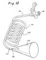
- FIG. 10is a perspective view of an alternate embodiment of the device including a distal tip emitting visible light
- FIG. 11is an enlarged perspective view of the distal end portion in another embodiment of the insufflation device.
- FIG. 12is an enlarged perspective view of the distal end portion in a further embodiment of the insufflation device.
- FIG. 13is an enlarged cross-section view of the abdominal wall showing an initial step in a preferred method for insertion of the device;
- FIG. 14is an enlarged cross-sectional view of the abdominal wall showing a continuing step in a preferred method for insertion
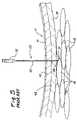
- FIG. 15is a close-up view of the abdominal wall illustrating a further step in the insertion method as the distal end emerges in close proximity to the internal organs of the patient;
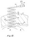
- FIG. 16is a schematic perspective view of the device within the abdominal wall
- FIG. 17is a perspective view of a wound site after removal of the device.
- FIG. 18is a front elevation view of a combination including an insufflation device rotatably attached to a trocar;
- FIG. 19is a front elevation view showing the combination of FIG. 18 in use to cross the abdominal wall;
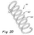
- FIGS. 20–26illustrate a further embodiment of the invention
- FIG. 20is a perspective view of the insufflation device or anchor associated with this embodiment.
- FIG. 21is an assembled view showing an obturator inserted into a cannula having an external helix
- FIG. 22is a side elevation view of the trocar and anchor of this embodiment.
- FIG. 23is a side elevation view showing engagement of the anchor by the trocar
- FIG. 24is a side elevation view of the trocar and anchor operably disposed in a perpendicular relationship with a body wall;
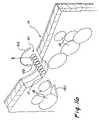
- FIG. 25is a side elevation view of the trocar and anchor operably disposed in an oblique relationship with the body wall;
- FIG. 26illustrates proximal external forces applied to the trocar to elevate the abdominal wall, while distal internal forces are applied to the trocar to penetrate the abdominal wall.
- FIG. 1A patient is illustrated in FIG. 1 and designated generally by the reference numeral 10 .
- the patient 10is shown in a prone position with his abdomen 12 facing upwardly as he is readied for laparoscopic surgery.
- minimally invasive surgeryis undertaken through an abdominal wall 14 and within an abdominal region 16 of the patient.
- This laparoscopic surgerycommonly involves internal organs 18 as best illustrated in FIG. 2 .
- laparoscopic surgerycalls for minimal invasion of the abdominal wall 14 through tubular access devices, commonly referred to as trocars.
- These trocarsare designated by the reference numeral 20 in FIG. 3 .
- the trocars 20are placed through small openings in the abdominal wall to provide access for visualization and surgical instruments. They are commonly provided with sharp points which although facilitating puncture of the abdominal wall, can be particularly threatening to the internal organs 18 which initially are in close proximity to the abdominal wall.
- This needle 23has included an elongate cannula 25 having a distal end 27 and a proximal end 30 .
- the cannulahas been provided with a sharp distal tip 31 of comparative interest to the present invention.
- the cannula 25has been coupled through a housing 32 to a connector 34 .
- a source of gas under pressure 36has been coupled to the connector 34 to provide the insufflation gas through the cannula 25 .
- the present procedure for placement of the Veress needlehas generally required that the needle be inserted perpendicular to the abdominal wall 14 . This has produced a perpendicular exit angle with an inner surface 39 of the abdominal wall 14 , and most importantly has produced a highly detrimental perpendicular relationship between the Veress needle 23 and the interior organs 18 .
- FIG. 5shows a greatly enlarged view of the abdominal wall 14 with the internal organs 18 in close proximity.
- the Veress needle 23has been forced through the abdominal wall 14 and the sharp distal tip 31 has just become exposed at an inner surface 39 of the abdominal wall 14 .
- the safety member 38has been deployed in this limited time and narrow space to shield the distal tip 31 .
- FIGS. 5 and 6It can be seen from FIGS. 5 and 6 that great care has been required during insertion of the Veress needle 23 in order to avoid damage to the adjacent internal organs 18 .
- the needle 23is commonly inserted through the abdominal wall 14 by pushing forward or distally.
- the forward motionmust be carefully controlled to avoid overshooting the abdominal wall 14 and inadvertently penetrating one of the internal organs 18 before the safety member 38 can respond and move forward to shield the sharp tip 31 .
- Thishas required that the spring force be carefully balanced between that which is required to penetrate the abdominal wall 14 and that which is required to prevent penetration of the internal organs 18 .
- the abdominal wall 14consists of skin 41 , layers of muscle 43 and a layer of connective tissue 45 .
- the peritoneumwhich forms the inner surface 39 of the abdominal wall 14 , may be very thin and delicate or it may be very tough.
- the safety member 38 associated with the distal end 27 of the Veress needle 23may be unable to respond in sufficient time to be effective, particularly if the peritoneum exerts an elastic load as the needle 23 is urged forward.
- an abrupt rupture of the peritoneummay allow a sharp, unshielded tip to penetrate the internal organs 18 before the safety member 38 can respond.
- FIG. 7a preferred embodiment of an insufflation device 101 of the present invention is shown in the configuration of a coil 102 formed of a spiraled length of hollow tubing 103 .
- the tubing 103has a diameter 104 , and an axis 105 extending between a proximal end 107 and a distal end 110 .
- a distal tip 111can be rounded or blunted to ensure that there are no sharp edges to cut or tear body tissue.
- the distal end 110may have at least one side port 112 that permits gas to escape from the lumen of the tubing 103 .
- the proximal end 107 of the coil 102may include a tubular extension 114 terminating in a connector 116 which is adapted to be coupled to the source of gas 36 ( FIG. 1 ).
- the coil 102can be formed with individual convolutions 118 which are spaced to provide maximum engagement with the body tissue while avoiding overcompression and necrosis of the tissue.
- the distal end 110 of the coiled insufflation device 101can be substantially or completely closed and formed with a hemispherical distal tip 111 providing a smooth transition to the coiled tubing 103 .
- the side port 112is preferably sized and configured to deliver maximum gas flow from the coiled tubing 103 to the abdominal cavity 21 .
- the distal tip 111is formed from a material that is optically clear.
- an optical viewing device 121such as an endoscope, angioscope or the like.
- the optical viewing device 121could be disposed in the lumen of the coiled tubing 103 and subsequently advanced to the distal end 110 for visually monitoring insertion of the insufflation device 101 .
- the optical viewing device 121may include an illumination device or light 130 within the lumen of the coiled tubing 103 .
- the light 130will produce an illuminated area 132 that is viewable from outside the body of the patient 10 .
- This form of viewingwhich is commonly referred to as transillumination, provides a clear indication as to the position of the distal end 110 when it has reached a preferred location.
- the indicationmay be some change in the emission characteristics of the light 130 , or may result from diffusion of the omitted light in a manner that indicates proper placement.
- the distal tip 111 of the coiled tubing 103may present an end condition that is not rounded.
- the coil tubing 103may terminate in a straight perpendicular surface 125 as illustrated in FIG. 11 .
- the lumen of the tubing 103would be unobstructed.
- the distal end 110is provided with a sharp, pointed tip 127 .
- the preferred embodiment of the present inventioncomprises a blunt or rounded tip
- the sharp tip 127 of FIG. 12 embodimentstill offers the significant advantage associated with the reduced entry and exit angles provided by the coil construction.
- FIGS. 13 , 14 , and 15show progressive positions of the insufflation device 101 as it is maneuvered through the abdominal wall 14 .
- a nick 134has been made in the skin 41 of the wall 14 .
- the entry angle of the distal tip 121can be increased to facilitate passage through the nick 134 .
- this entry angleis designated by the Greek letter ⁇ .
- the coil 102is preferably oriented so that its axis 105 is substantially perpendicular to the abdominal wall 14 as illustrated in FIG. 14 . This greatly reduces the entry angle ⁇ as the distal tip 121 passes through the layer of muscle 43 and associated connective tissue 45 ( FIG. 5 ) which comprise the abdominal wall 14 .
- FIG. 14Continued penetration of the coiled tubing 103 through the abdominal wall 14 is illustrated in FIG. 14 .
- the distal tip and the following convolutions 118exit the wall 14 at an exit angle designated by the Greek letter ⁇ in FIG. 15 .
- this exit angle ⁇is of particular importance to the present invention. Although this angle is measured with respect to an inner surface 136 of the abdominal wall 14 , it can be appreciated that the internal organs 18 are also in contact with, or generally parallel to this inner surface 136 . Accordingly, the exit angle ⁇ is also the angle which the distal tip 121 presents to the internal organs 18 . When this angle is generally perpendicular, as in the past (see FIG. 6 ), the probability of organ penetration is great. However, when this exit angle ⁇ is reduced to a very small acute angle, the distal tip 111 tends to slide along the surface of the internal organs 18 , particularly if the distal tip 111 has a blunt configuration as first discussed with reference to FIG. 8 .
- the coiled device 101 of the present inventionis illustrated schematically so that one can appreciate the forces associated with placement of the device 101 through the body wall 14 .
- the straight Veress needle 23FIG. 1
- the straight Veress needle 23would be placed using a force applied in the same direction as that desired for movement of the device 101 , specifically a forward force applied in the direction represented by an arrow 150 .
- the insufflation device 101 of the present embodimentmoves in the desired forward direction 150 , but does so only in response to a rotational force represented by an arrow 152 .
- the forward direction of movement illustrated by the arrow 150may even be realized while the coiled tubing 103 is pulled backwardly by a force opposite to the forward direction of arrow 150 .
- the entire device 101may be held in traction rather than pushed to provide the desired forward motion.
- the coiled tubing 103acts as a “corkscrew” and propels or advances itself in the forward direction 150 , but only in response to rotational motion shown by arrow 152 . This tractional rotation of the coiled tubing 103 tends to provide a safety margin as the body wall 14 is pulled or drawn away from the internal organs 18 .
- the present inventionmay comprise larger than ordinary tubing 103 since the placement force is not perpendicular to the abdominal wall 14 and internal organs 18 .
- the placement forceas shown by arrow 152 , is rotational and incremental rather than direct and uncontrollable.
- the slow and deliberate advancement of the blunt distal end 110gradually parts tissue, such as the skin 41 , muscle 43 , and connective tissue 45 in a more natural manner than with the straight, cutting penetration of the past.
- the blunt distal end 110tends to wind its way through body tissue seeking weak, less dense or fatty tissue, and avoiding included blood vessels, and muscle that is normally more vascular than fatty tissue.
- FIG. 17An insertion site 21 associated with the present invention is shown in FIG. 17 at a time when the device 101 has been removed, and the tissue, previously separated by the procedure, has generally returned to its original condition. Since little or no cutting has occurred, there is minimal bleeding and no potential for herniation of the site.
- a track 138 through which the device 101 passes as it is rotated through the tissue,has the same length and convoluted nature as the device 101 itself. With respect to the track 138 , its length, convoluted nature and general lack of cut tissue provides improved healing even though the diameter size of the insufflation device 101 may have been as much as two or three times that of existing insufflation needles.
- the insufflation device 101can provide a gas flow significantly greater than existing insufflation needles. But even if the diameter or gauge size of the present insufflation device 101 is the same as that of the prior art, its gas flow will be significantly greater primarily due to the lack of obstruction in the lumen of the tubing 103 .
- the coiled insufflation device 101can be further appreciated in combination with a trocar, such as the trocar 20 discussed with reference to FIG. 3 .
- the trocar 20is shown to have a valve housing 141 , a cannula 143 , and a removable obturator 145 .
- the coiled insufflation device 101is rotatably attached to the trocar 20 , for example with an attachment ring 147 .
- the trocar 20is preferably disposed inside of and coaxial with the coiled insufflation device 101 . With this orientation, the device 101 is free to rotate on its axis around the cannula 143 of the trocar 20 .
- the device 101will typically be as long as, if not slightly longer than, the cannula 143 so that the distal tip 111 extends at least to the tip of the obturator 145 .
- FIG. 19Operation of this combination is illustrated in FIG. 19 .
- the coiled insufflation device 101As the coiled insufflation device 101 is rotated into the abdominal wall 14 of the patient, it advances in the manner previously discussed. Due to its attachment to the trocar 20 , this advancement tends to pull the trocar into the abdominal wall 14 .
- One major advantage associated with this combinationis that the device 101 provides an outward counter force which resists any tendency of the abdominal wall 14 to tent inwardly due to the forward movement of the trocar 20 .
- This systemwould be particularly useful for bariatric patients which have a large quantity of abdominal wall fat.
- these patientsoften a large amount of leverage must be applied against the trocar to overcome the bulk of abdominal wall fat. This in turn widens the trocar entry wound and makes slippage of the trocar more likely.
- the surgeondoes not have to fight the abdominal wall during insertion and will further benefit from the tremendous retention provided by the insufflation device 101 .
- trocarsare typically placed normal to the surface of the abdominal wall 14 and also normal to the peritoneum.
- an inwardly directed forcewas applied to the trocar 20 to push the trocar 20 through the abdominal wall 14 .
- This forcecaused the abdominal wall to tent inwardly as the force was directed against succeeding muscular and fat layers of the wall 14 .
- the forcewas directed against the peritoneum and tended to separate the peritoneum from the remainder of the abdominal wall.
- the device 101can be pulled with an outwardly directed force while the trocar 20 is pushed with an inwardly directed force.
- the outward forceexceeds the inward force, two significant advantages are realized.
- the device 101provides a further advantage as it functions to hold the peritoneum against the remainder of the abdominal wall 14 .
- This featureresists any tendency toward peritoneal separation regardless of its cause.
- angular placement of the trocar 20can be accommodated without a risk of separating the peritoneum from the adjacent layer of the abdominal wall 14 .
- Angular placementwill also enable the surgeon to reach lateral internal sites more easily, without forcing the trocar 20 to cant with commensurate stress on the instruments.
- FIGS. 21–24A further embodiment of the invention is illustrated in FIGS. 21–24 .
- This embodimentis similar to that of FIG. 18 in that it includes the insufflation device 101 ( FIG. 20 ), the trocar 20 with cannula 143 ( FIG. 21 ), and the obturator 145 ( FIG. 21 ).
- FIG. 21differs from that of FIG. 18 in at least two aspects.
- the insufflation device 101is not attached to the trocar, but rather is separate from the trocar to permit the unique operation discussed in greater detail below.
- a helix 161is formed on the outer surface of the cannula 143 of the trocar 20 .
- This helix 161can be formed with multiple convolutions or preferrably with only a single convolution 163 .
- the helix 161functions as an external thread on the trocar 20 . Its preferred placement could be anywhere along the cannula 143 , or perhaps even on the exposed distal tip of the obturator 145 .
- the insufflation device 101can function in this embodiment as an anchor 167 which can be embedded in the abdominal wall 14 in the manner previously discussed.
- the anchor 167can function as an insufflation needle; however, in this case the anchor 167 has an additional purpose and that is to provide the helix or coil 102 which can function as an internal thread.
- the trocar 20 with its external thread or helix 161can be screwed into the anchor 167 thereby drawing the trocar 20 through the abdominal wall 14 .
- an internal forceis developed between these two structures which moves the trocar 20 forward or distally into the abdominal wall 14 .
- No directional external forceis required to produce this forward movement.
- the usermerely rotates the trocar 20 as shown by the arrows 169 , to produce the internal force that draws the trocar 20 into the abdominal wall 14 .
- the system and method associated with this embodimentis particularly beneficial when the trocar 20 is to be inserted at a non-perpendicular angle to the abdominal wall 14 .
- the trocar 20is to be inserted at an angle to the abdominal wall 14 .
- thiswould ultimately bring the distal trip of the obturator into an angular relationship with the peritoneum 171 of the abdominal wall 14 .
- the peritoneum 171forms a relatively strong inner surface of the wall 14
- an angular relationship with the trocars of the pasthas tended to resist penetration of the peritoneum 171 and ultimately separated the peritoneum 171 from the remainder of the wall 14 .
- the anchor 167is initially placed at the preferred angle, as illustrated in FIG. 25 . Then the trocar 20 is merely threaded along the axis of the anchor 167 . In this case, the anchor 167 defines the pathway through the peritoneum 171 and provides a continuous axial force which draws the trocar 20 along the axis of the anchor 167 . In this manner, an angular placement of the trocar 20 can be easily achieved without substantial risk of peritoneal separation.
- the anchor 167can function as an insufflation needle as discussed with reference to previous embodiments. However, certainly one of its primary functions is to helically receive the trocar 20 even while it is being inserted. Once the trocar 20 engages the anchor 167 , a rearward or proximate force can be applied to the trocar 20 to elevate the abdominal wall 14 and thereby create the abdominal cavity 21 . This external force would typically be applied along the arrow 173 as illustrated in FIG. 24 .
- the anchor 167is initially inserted into the abdominal wall 14 in the manner previously discussed. Then the user moves the cannula 143 of the trocar 20 along the axis of the anchor 167 until the external thread or helix 161 engages the internal thread or coil 102 of the anchor 167 . The user can then merely turn the trocar in the direction of the arrows 167 to provide an engagement between the helix 161 and coil 102 . Once this engagement is achieved, the user can pull the trocar 20 proximally along the arrow 173 to elevate the abdominal wall 14 and produce the abdominal cavity 21 .
Landscapes
- Health & Medical Sciences (AREA)
- Life Sciences & Earth Sciences (AREA)
- Surgery (AREA)
- Animal Behavior & Ethology (AREA)
- General Health & Medical Sciences (AREA)
- Engineering & Computer Science (AREA)
- Biomedical Technology (AREA)
- Heart & Thoracic Surgery (AREA)
- Veterinary Medicine (AREA)
- Public Health (AREA)
- Medical Informatics (AREA)
- Pathology (AREA)
- Molecular Biology (AREA)
- Nuclear Medicine, Radiotherapy & Molecular Imaging (AREA)
- Biophysics (AREA)
- Pulmonology (AREA)
- Anesthesiology (AREA)
- Hematology (AREA)
- Oral & Maxillofacial Surgery (AREA)
- Surgical Instruments (AREA)
- Endoscopes (AREA)
Abstract
Description
Claims (14)
Priority Applications (8)
| Application Number | Priority Date | Filing Date | Title |
|---|---|---|---|
| US10/379,461US7070586B2 (en) | 2003-01-17 | 2003-03-03 | Surgical access apparatus and method |
| EP04712378AEP1601403A4 (en) | 2003-03-03 | 2004-02-18 | Surgical access apparatus and method |
| JP2006508766AJP2006519084A (en) | 2003-03-03 | 2004-02-18 | Surgical access device and method |
| CA002516617ACA2516617A1 (en) | 2003-03-03 | 2004-02-18 | Surgical access apparatus and method |
| PCT/US2004/004883WO2004078026A2 (en) | 2003-03-03 | 2004-02-18 | Surgical access apparatus and method |
| AU2004218514AAU2004218514A1 (en) | 2003-03-03 | 2004-02-18 | Surgical access apparatus and method |
| US11/383,927US7942862B2 (en) | 2003-01-17 | 2006-05-17 | Surgical access apparatus and method |
| US13/078,750US8961493B2 (en) | 2003-01-17 | 2011-04-01 | Surgical access apparatus and method |
Applications Claiming Priority (2)
| Application Number | Priority Date | Filing Date | Title |
|---|---|---|---|
| US10/346,846US6887194B2 (en) | 2003-01-17 | 2003-01-17 | Surgical access apparatus and method |
| US10/379,461US7070586B2 (en) | 2003-01-17 | 2003-03-03 | Surgical access apparatus and method |
Related Parent Applications (1)
| Application Number | Title | Priority Date | Filing Date |
|---|---|---|---|
| US10/346,846Continuation-In-PartUS6887194B2 (en) | 2003-01-17 | 2003-01-17 | Surgical access apparatus and method |
Related Child Applications (1)
| Application Number | Title | Priority Date | Filing Date |
|---|---|---|---|
| US11/383,927ContinuationUS7942862B2 (en) | 2003-01-17 | 2006-05-17 | Surgical access apparatus and method |
Publications (2)
| Publication Number | Publication Date |
|---|---|
| US20040143237A1 US20040143237A1 (en) | 2004-07-22 |
| US7070586B2true US7070586B2 (en) | 2006-07-04 |
Family
ID=32961269
Family Applications (3)
| Application Number | Title | Priority Date | Filing Date |
|---|---|---|---|
| US10/379,461Expired - LifetimeUS7070586B2 (en) | 2003-01-17 | 2003-03-03 | Surgical access apparatus and method |
| US11/383,927Expired - Fee RelatedUS7942862B2 (en) | 2003-01-17 | 2006-05-17 | Surgical access apparatus and method |
| US13/078,750Expired - Fee RelatedUS8961493B2 (en) | 2003-01-17 | 2011-04-01 | Surgical access apparatus and method |
Family Applications After (2)
| Application Number | Title | Priority Date | Filing Date |
|---|---|---|---|
| US11/383,927Expired - Fee RelatedUS7942862B2 (en) | 2003-01-17 | 2006-05-17 | Surgical access apparatus and method |
| US13/078,750Expired - Fee RelatedUS8961493B2 (en) | 2003-01-17 | 2011-04-01 | Surgical access apparatus and method |
Country Status (6)
| Country | Link |
|---|---|
| US (3) | US7070586B2 (en) |
| EP (1) | EP1601403A4 (en) |
| JP (1) | JP2006519084A (en) |
| AU (1) | AU2004218514A1 (en) |
| CA (1) | CA2516617A1 (en) |
| WO (1) | WO2004078026A2 (en) |
Cited By (35)
| Publication number | Priority date | Publication date | Assignee | Title |
|---|---|---|---|---|
| US20080154314A1 (en)* | 2006-08-16 | 2008-06-26 | Mcdevitt Dennis M | Composite interference screw for attaching a graft ligament to a bone, and other apparatus for making attachments to bone |
| US20080171988A1 (en)* | 2007-01-17 | 2008-07-17 | Erblan Surgical, Inc. | Double-cone sphincter introducer assembly and integrated valve assembly |
| US20090319043A1 (en)* | 2007-08-16 | 2009-12-24 | Mcdevitt Dennis | Helicoil interference fixation system for attaching a graft ligament to a bone |
| US20090326461A1 (en)* | 2008-06-27 | 2009-12-31 | Tyco Healthcare Group Lp | Low profile instrument access device |
| US20100194060A1 (en)* | 2008-11-03 | 2010-08-05 | Erblan Surgical, Inc. | Universal closure and method of lubrication |
| US20100234806A1 (en)* | 2009-03-10 | 2010-09-16 | Tyco Healthcare Group Lp | Port fixation using expandable threads |
| US8235942B2 (en) | 2005-05-04 | 2012-08-07 | Olympus Endo Technology America Inc. | Rotate-to-advance catheterization system |
| US8317678B2 (en) | 2005-05-04 | 2012-11-27 | Olympus Endo Technology America Inc. | Rotate-to-advance catheterization system |
| US8343040B2 (en) | 2005-05-04 | 2013-01-01 | Olympus Endo Technology America Inc. | Rotate-to-advance catheterization system |
| US8366674B2 (en) | 2005-05-04 | 2013-02-05 | Olympus Endo Technology America Inc. | Rotate-to-advance catheterization system |
| US8377041B2 (en) | 2005-02-28 | 2013-02-19 | Olympus Endo Technology America Inc. | Rotate-to-advance catheterization system |
| US8377090B2 (en) | 2002-05-16 | 2013-02-19 | Applied Medical Resources Corporation | Blunt tip obturator |
| US8414477B2 (en) | 2005-05-04 | 2013-04-09 | Olympus Endo Technology America Inc. | Rotate-to-advance catheterization system |
| US8435229B2 (en) | 2006-02-28 | 2013-05-07 | Olympus Endo Technology America Inc. | Rotate-to-advance catheterization system |
| US8517977B2 (en)* | 2006-10-06 | 2013-08-27 | Applied Medical Resources Corporation | Visual insufflation port |
| US8574220B2 (en) | 2006-02-28 | 2013-11-05 | Olympus Endo Technology America Inc. | Rotate-to-advance catheterization system |
| US8608769B2 (en) | 2001-09-24 | 2013-12-17 | Applied Medical Resources Corporation | Bladeless optical obturator |
| US8636759B2 (en) | 2001-09-24 | 2014-01-28 | Applied Medical Resources Corporation | Bladeless obturator |
| US20140100431A1 (en)* | 2012-10-05 | 2014-04-10 | Fox Chase Cancer Center | Method for inserting medical instrument |
| US8764631B2 (en) | 1997-02-10 | 2014-07-01 | Olympus Endo Technology America Inc. | Rotate to advance catheterization system |
| US8777841B2 (en) | 2007-05-18 | 2014-07-15 | Olympus Endo Technology America Inc. | Rotate-to-advance catheterization system |
| US8795326B2 (en) | 2007-10-05 | 2014-08-05 | Covidien Lp | Expanding seal anchor for single incision surgery |
| US8979865B2 (en) | 2010-03-10 | 2015-03-17 | Smith & Nephew, Inc. | Composite interference screws and drivers |
| US9155531B2 (en) | 2013-03-15 | 2015-10-13 | Smith & Nephew, Inc. | Miniaturized dual drive open architecture suture anchor |
| US9155558B2 (en) | 2004-06-29 | 2015-10-13 | Applied Medical Resources Corporation | Insufflating optical surgical instrument |
| US9220395B2 (en) | 1999-09-27 | 2015-12-29 | James J. Frassica | Rotate-to-advance catheterization system |
| US9254148B2 (en) | 2011-05-02 | 2016-02-09 | Applied Medical Resources Corporation | Low-profile surgical universal access port |
| US9265899B2 (en) | 2008-01-25 | 2016-02-23 | Applied Medical Resources Corporation | Insufflating access system |
| US9308080B2 (en) | 2010-03-10 | 2016-04-12 | Smith & Nephew Inc. | Composite interference screws and drivers |
| US9314266B2 (en) | 2008-09-29 | 2016-04-19 | Applied Medical Resources Corporation | First-entry trocar system |
| US9579188B2 (en) | 2010-03-10 | 2017-02-28 | Smith & Nephew, Inc. | Anchor having a controlled driver orientation |
| US9775702B2 (en) | 2010-03-10 | 2017-10-03 | Smith & Nephew, Inc. | Composite interference screws and drivers |
| US9808298B2 (en) | 2013-04-09 | 2017-11-07 | Smith & Nephew, Inc. | Open-architecture interference screw |
| US9901355B2 (en) | 2011-03-11 | 2018-02-27 | Smith & Nephew, Inc. | Trephine |
| US9924934B2 (en) | 2011-06-07 | 2018-03-27 | Smith & Nephew, Inc. | Surgical anchor delivery system |
Families Citing this family (13)
| Publication number | Priority date | Publication date | Assignee | Title |
|---|---|---|---|---|
| ES2385982T3 (en)* | 2003-02-25 | 2012-08-06 | Chemetall Gmbh | Procedure for coating metal surfaces with a silane-rich composition |
| US7811251B2 (en)* | 2005-10-13 | 2010-10-12 | Tyco Healthcare Group Lp | Trocar anchor |
| US20100228233A1 (en)* | 2006-02-23 | 2010-09-09 | Darren Kahn | Medical device for infusion having coiled tubing of adjustable length |
| AU2007223403B2 (en) | 2006-03-01 | 2013-03-28 | Applied Medical Resources Corporation | Gas insufflation suction and irrigation medical tubing |
| USD558339S1 (en)* | 2006-09-09 | 2007-12-25 | Cs Medical, Inc. | Combined tracheal catheter and connector |
| EP2182853A4 (en) | 2007-08-10 | 2012-08-08 | Univ Yale | SUSPENSION / RETRACTION DEVICE FOR SURGICAL HANDLING |
| AU2008302043B2 (en) | 2007-09-21 | 2013-06-27 | Covidien Lp | Surgical device |
| US20100262079A1 (en)* | 2009-04-13 | 2010-10-14 | Tyco Healthcare Group Lp | Bendable veress needle assembly |
| US20100274081A1 (en)* | 2009-04-22 | 2010-10-28 | Tyco Healthcare Group Lp | Visual veress needle assembly |
| CA2786908A1 (en)* | 2010-02-05 | 2011-08-11 | Boston Scientific Scimed, Inc. | Flexible endoscopic ultrasound guided biopsy device |
| CA2839282A1 (en) | 2011-06-28 | 2013-01-03 | Novatract Surgical, Inc. | Tissue retractor assembly |
| US9132065B2 (en) | 2012-04-30 | 2015-09-15 | Cook Medical Technologies Llc | Enteral feeding percutaneous access clip |
| AU2019408052B2 (en)* | 2018-12-21 | 2025-04-03 | University of Galway | A medical anchor device |
Citations (9)
| Publication number | Priority date | Publication date | Assignee | Title |
|---|---|---|---|---|
| US5334150A (en) | 1992-11-17 | 1994-08-02 | Kaali Steven G | Visually directed trocar for laparoscopic surgical procedures and method of using same |
| US5407427A (en)* | 1992-06-16 | 1995-04-18 | Loma Linda University Medical Center | Trocar facilitator for endoscopic surgery |
| US5443484A (en) | 1992-06-16 | 1995-08-22 | Loma Linda University Medical Center | Trocar and method for endoscopic surgery |
| US5695462A (en)* | 1996-01-18 | 1997-12-09 | Conmed Corporation | Gas insufflation needle apparatus and method of use |
| US5957888A (en)* | 1995-10-10 | 1999-09-28 | United States Surgical Corporation | Surgical cannula having a variable length |
| US5976079A (en)* | 1995-12-20 | 1999-11-02 | Fraunhofer Gesellschaft Zur Foerderung Der Angewandten Forschung E.V. | Device for lifting the abdominal wall for conducting endoscopic examinations including surgery |
| US6001084A (en) | 1995-12-18 | 1999-12-14 | Riek; Siegfried | Medical needle for endoscopic surgery |
| US6508759B1 (en)* | 1993-10-08 | 2003-01-21 | Heartport, Inc. | Stereoscopic percutaneous visualization system |
| US20050107803A1 (en)* | 2003-11-14 | 2005-05-19 | Guanche Carlos A. | Cannula delivery and support system |
Family Cites Families (14)
| Publication number | Priority date | Publication date | Assignee | Title |
|---|---|---|---|---|
| US4254762A (en) | 1979-10-23 | 1981-03-10 | Inbae Yoon | Safety endoscope system |
| US4762130A (en) | 1987-01-15 | 1988-08-09 | Thomas J. Fogarty | Catheter with corkscrew-like balloon |
| US4878492A (en)* | 1987-10-08 | 1989-11-07 | C. R. Bard, Inc. | Laser balloon catheter |
| US5685820A (en) | 1990-11-06 | 1997-11-11 | Partomed Medizintechnik Gmbh | Instrument for the penetration of body tissue |
| US5538509A (en) | 1994-01-31 | 1996-07-23 | Richard-Allan Medical Industries, Inc. | Trocar assembly |
| US5478329A (en) | 1994-05-06 | 1995-12-26 | Ternamian; Artin M. | Trocarless rotational entry cannula |
| WO1996001132A1 (en) | 1994-07-01 | 1996-01-18 | Northgate Technologies Incorporated | High flow insufflation instrument for laparoscopic surgery |
| US5658306A (en)* | 1994-07-01 | 1997-08-19 | Archimedes Surgical, Inc. | Method for making additional incisions in laparoscopic surgery |
| US5738628A (en) | 1995-03-24 | 1998-04-14 | Ethicon Endo-Surgery, Inc. | Surgical dissector and method for its use |
| US6068637A (en) | 1995-10-03 | 2000-05-30 | Cedar Sinai Medical Center | Method and devices for performing vascular anastomosis |
| DE29521431U1 (en) | 1995-12-18 | 1997-04-30 | Bachmann, Karl-Heinz, 78667 Villingendorf | Medical needle |
| US5842971A (en) | 1996-05-22 | 1998-12-01 | Yoon; Inbae | Optical endoscopic portals and methods of using the same to establish passages through cavity walls |
| US6468228B1 (en)* | 1996-06-18 | 2002-10-22 | Vance Products Incorporated | Surgical tissue morcellator |
| US6471638B1 (en)* | 2000-04-28 | 2002-10-29 | Origin Medsystems, Inc. | Surgical apparatus |
- 2003
- 2003-03-03USUS10/379,461patent/US7070586B2/ennot_activeExpired - Lifetime
- 2004
- 2004-02-18EPEP04712378Apatent/EP1601403A4/ennot_activeWithdrawn
- 2004-02-18CACA002516617Apatent/CA2516617A1/ennot_activeAbandoned
- 2004-02-18JPJP2006508766Apatent/JP2006519084A/enactivePending
- 2004-02-18AUAU2004218514Apatent/AU2004218514A1/ennot_activeAbandoned
- 2004-02-18WOPCT/US2004/004883patent/WO2004078026A2/enactiveApplication Filing
- 2006
- 2006-05-17USUS11/383,927patent/US7942862B2/ennot_activeExpired - Fee Related
- 2011
- 2011-04-01USUS13/078,750patent/US8961493B2/ennot_activeExpired - Fee Related
Patent Citations (10)
| Publication number | Priority date | Publication date | Assignee | Title |
|---|---|---|---|---|
| US5407427A (en)* | 1992-06-16 | 1995-04-18 | Loma Linda University Medical Center | Trocar facilitator for endoscopic surgery |
| US5443484A (en) | 1992-06-16 | 1995-08-22 | Loma Linda University Medical Center | Trocar and method for endoscopic surgery |
| US5577993A (en) | 1992-06-16 | 1996-11-26 | Loma Linda University Medical Center | Trocar facilitator for endoscopic surgery and method of using the same |
| US5334150A (en) | 1992-11-17 | 1994-08-02 | Kaali Steven G | Visually directed trocar for laparoscopic surgical procedures and method of using same |
| US6508759B1 (en)* | 1993-10-08 | 2003-01-21 | Heartport, Inc. | Stereoscopic percutaneous visualization system |
| US5957888A (en)* | 1995-10-10 | 1999-09-28 | United States Surgical Corporation | Surgical cannula having a variable length |
| US6001084A (en) | 1995-12-18 | 1999-12-14 | Riek; Siegfried | Medical needle for endoscopic surgery |
| US5976079A (en)* | 1995-12-20 | 1999-11-02 | Fraunhofer Gesellschaft Zur Foerderung Der Angewandten Forschung E.V. | Device for lifting the abdominal wall for conducting endoscopic examinations including surgery |
| US5695462A (en)* | 1996-01-18 | 1997-12-09 | Conmed Corporation | Gas insufflation needle apparatus and method of use |
| US20050107803A1 (en)* | 2003-11-14 | 2005-05-19 | Guanche Carlos A. | Cannula delivery and support system |
Cited By (64)
| Publication number | Priority date | Publication date | Assignee | Title |
|---|---|---|---|---|
| US8764631B2 (en) | 1997-02-10 | 2014-07-01 | Olympus Endo Technology America Inc. | Rotate to advance catheterization system |
| US9220395B2 (en) | 1999-09-27 | 2015-12-29 | James J. Frassica | Rotate-to-advance catheterization system |
| US8608769B2 (en) | 2001-09-24 | 2013-12-17 | Applied Medical Resources Corporation | Bladeless optical obturator |
| US9655643B2 (en) | 2001-09-24 | 2017-05-23 | Applied Medical Resources Corporation | Bladeless optical obturator |
| US10568658B2 (en) | 2001-09-24 | 2020-02-25 | Applied Medical Resources Corporation | Bladeless optical obturator |
| US9254125B2 (en) | 2001-09-24 | 2016-02-09 | Applied Medical Resources Corporation | Bladeless obturator |
| US8636759B2 (en) | 2001-09-24 | 2014-01-28 | Applied Medical Resources Corporation | Bladeless obturator |
| US8940009B2 (en) | 2001-09-24 | 2015-01-27 | Applied Medical Resources Corporation | Bladeless optical obturator |
| US9545248B2 (en) | 2002-05-16 | 2017-01-17 | Applied Medical Resources Corporation | Blunt tip obturator |
| US11207098B2 (en) | 2002-05-16 | 2021-12-28 | Applied Medical Resources Corporation | Blunt tip obturator |
| US10368906B2 (en) | 2002-05-16 | 2019-08-06 | Applied Medical Resources Corporation | Blunt tip obturator |
| US8377090B2 (en) | 2002-05-16 | 2013-02-19 | Applied Medical Resources Corporation | Blunt tip obturator |
| US8608768B2 (en) | 2002-05-16 | 2013-12-17 | Applied Medical Resources Corporation | Blunt tip obturator |
| US10226589B2 (en) | 2003-10-03 | 2019-03-12 | Applied Medical Resources Corporation | Insufflating optical surgical instrument |
| US10918814B2 (en) | 2003-10-03 | 2021-02-16 | Applied Medical Resources Corporation | Insufflating optical surgical instrument |
| US9155558B2 (en) | 2004-06-29 | 2015-10-13 | Applied Medical Resources Corporation | Insufflating optical surgical instrument |
| US8377041B2 (en) | 2005-02-28 | 2013-02-19 | Olympus Endo Technology America Inc. | Rotate-to-advance catheterization system |
| US8343040B2 (en) | 2005-05-04 | 2013-01-01 | Olympus Endo Technology America Inc. | Rotate-to-advance catheterization system |
| US8317678B2 (en) | 2005-05-04 | 2012-11-27 | Olympus Endo Technology America Inc. | Rotate-to-advance catheterization system |
| US8235942B2 (en) | 2005-05-04 | 2012-08-07 | Olympus Endo Technology America Inc. | Rotate-to-advance catheterization system |
| US8747300B2 (en) | 2005-05-04 | 2014-06-10 | Olympus Endo Technology America Inc. | Rotate-to-advance catheterization system |
| US8414477B2 (en) | 2005-05-04 | 2013-04-09 | Olympus Endo Technology America Inc. | Rotate-to-advance catheterization system |
| US8366674B2 (en) | 2005-05-04 | 2013-02-05 | Olympus Endo Technology America Inc. | Rotate-to-advance catheterization system |
| US8435229B2 (en) | 2006-02-28 | 2013-05-07 | Olympus Endo Technology America Inc. | Rotate-to-advance catheterization system |
| US8574220B2 (en) | 2006-02-28 | 2013-11-05 | Olympus Endo Technology America Inc. | Rotate-to-advance catheterization system |
| US20080154314A1 (en)* | 2006-08-16 | 2008-06-26 | Mcdevitt Dennis M | Composite interference screw for attaching a graft ligament to a bone, and other apparatus for making attachments to bone |
| US8992612B2 (en) | 2006-08-16 | 2015-03-31 | Smith & Nephew, Inc. | Helicoil interference fixation system for attaching a graft ligament to a bone |
| US9492062B2 (en) | 2006-10-06 | 2016-11-15 | Applied Medical Resources Corporation | Visual insufflation port |
| US11123105B2 (en) | 2006-10-06 | 2021-09-21 | Applied Medical Resources Corporation | Visual insufflation port |
| US8517977B2 (en)* | 2006-10-06 | 2013-08-27 | Applied Medical Resources Corporation | Visual insufflation port |
| US20080171988A1 (en)* | 2007-01-17 | 2008-07-17 | Erblan Surgical, Inc. | Double-cone sphincter introducer assembly and integrated valve assembly |
| US8777841B2 (en) | 2007-05-18 | 2014-07-15 | Olympus Endo Technology America Inc. | Rotate-to-advance catheterization system |
| US8870755B2 (en) | 2007-05-18 | 2014-10-28 | Olympus Endo Technology America Inc. | Rotate-to-advance catheterization system |
| US20090319043A1 (en)* | 2007-08-16 | 2009-12-24 | Mcdevitt Dennis | Helicoil interference fixation system for attaching a graft ligament to a bone |
| US8894661B2 (en) | 2007-08-16 | 2014-11-25 | Smith & Nephew, Inc. | Helicoil interference fixation system for attaching a graft ligament to a bone |
| US9474518B2 (en) | 2007-10-05 | 2016-10-25 | Covidien Lp | Expanding seal anchor for single incision surgery |
| US8795326B2 (en) | 2007-10-05 | 2014-08-05 | Covidien Lp | Expanding seal anchor for single incision surgery |
| US9265899B2 (en) | 2008-01-25 | 2016-02-23 | Applied Medical Resources Corporation | Insufflating access system |
| US8092423B2 (en) | 2008-06-27 | 2012-01-10 | Tyco Healthcare Group Lp | Low profile instrument access device |
| US7850667B2 (en) | 2008-06-27 | 2010-12-14 | Tyco Healthcare Group Lp | Low profile instrument access device |
| US20110077597A1 (en)* | 2008-06-27 | 2011-03-31 | Tyco Healthcare Group Lp | Low profile instrument access device |
| US20090326461A1 (en)* | 2008-06-27 | 2009-12-31 | Tyco Healthcare Group Lp | Low profile instrument access device |
| US9314266B2 (en) | 2008-09-29 | 2016-04-19 | Applied Medical Resources Corporation | First-entry trocar system |
| US9358040B2 (en) | 2008-09-29 | 2016-06-07 | Applied Medical Resources Corporation | First-entry trocar system |
| US10856906B2 (en) | 2008-09-29 | 2020-12-08 | Applied Medical Resources Corporation | First-entry trocar system |
| US10022150B2 (en) | 2008-09-29 | 2018-07-17 | Applied Medical Resources Corporation | First-entry trocar system |
| US11723689B2 (en) | 2008-09-29 | 2023-08-15 | Applied Medical Resources Corporation | First-entry trocar system |
| US20100194060A1 (en)* | 2008-11-03 | 2010-08-05 | Erblan Surgical, Inc. | Universal closure and method of lubrication |
| US7857789B2 (en)* | 2009-03-10 | 2010-12-28 | Tyco Healthcare Group Lp | Port fixation using expandable threads |
| US20100234806A1 (en)* | 2009-03-10 | 2010-09-16 | Tyco Healthcare Group Lp | Port fixation using expandable threads |
| US8979865B2 (en) | 2010-03-10 | 2015-03-17 | Smith & Nephew, Inc. | Composite interference screws and drivers |
| US9308080B2 (en) | 2010-03-10 | 2016-04-12 | Smith & Nephew Inc. | Composite interference screws and drivers |
| US9808337B2 (en) | 2010-03-10 | 2017-11-07 | Smith & Nephew, Inc. | Composite interference screws and drivers |
| US9579188B2 (en) | 2010-03-10 | 2017-02-28 | Smith & Nephew, Inc. | Anchor having a controlled driver orientation |
| US9775702B2 (en) | 2010-03-10 | 2017-10-03 | Smith & Nephew, Inc. | Composite interference screws and drivers |
| US9788935B2 (en) | 2010-03-10 | 2017-10-17 | Smith & Nephew, Inc. | Composite interference screws and drivers |
| US9901355B2 (en) | 2011-03-11 | 2018-02-27 | Smith & Nephew, Inc. | Trephine |
| US9254148B2 (en) | 2011-05-02 | 2016-02-09 | Applied Medical Resources Corporation | Low-profile surgical universal access port |
| US9924934B2 (en) | 2011-06-07 | 2018-03-27 | Smith & Nephew, Inc. | Surgical anchor delivery system |
| US9597061B2 (en)* | 2012-10-05 | 2017-03-21 | The Institute For Cancer Research | Method for inserting medical instrument |
| US20140100431A1 (en)* | 2012-10-05 | 2014-04-10 | Fox Chase Cancer Center | Method for inserting medical instrument |
| US9788828B2 (en) | 2013-03-15 | 2017-10-17 | Smith & Nephew, Inc. | Miniaturized dual drive open architecture suture anchor |
| US9155531B2 (en) | 2013-03-15 | 2015-10-13 | Smith & Nephew, Inc. | Miniaturized dual drive open architecture suture anchor |
| US9808298B2 (en) | 2013-04-09 | 2017-11-07 | Smith & Nephew, Inc. | Open-architecture interference screw |
Also Published As
| Publication number | Publication date |
|---|---|
| CA2516617A1 (en) | 2004-09-16 |
| US7942862B2 (en) | 2011-05-17 |
| WO2004078026A2 (en) | 2004-09-16 |
| US20040143237A1 (en) | 2004-07-22 |
| US8961493B2 (en) | 2015-02-24 |
| AU2004218514A1 (en) | 2004-09-16 |
| US20110196307A1 (en) | 2011-08-11 |
| JP2006519084A (en) | 2006-08-24 |
| US20060217681A1 (en) | 2006-09-28 |
| EP1601403A4 (en) | 2008-06-18 |
| WO2004078026A3 (en) | 2005-05-19 |
| EP1601403A2 (en) | 2005-12-07 |
Similar Documents
| Publication | Publication Date | Title |
|---|---|---|
| US7070586B2 (en) | Surgical access apparatus and method | |
| US8105285B2 (en) | Surgical access apparatus and method | |
| US10568658B2 (en) | Bladeless optical obturator | |
| EP3744271B1 (en) | Insufflating optical surgical instrument | |
| US5630805A (en) | Method for accessing the peritoneal cavity | |
| EP2428171B1 (en) | Bladeless Obturator | |
| US7758603B2 (en) | Blunt tip obturator | |
| EP1983910B1 (en) | Trocars with advanced fixation | |
| US20070049963A1 (en) | Direct vision port site dissector | |
| GB2378138A (en) | Device for assisting laparoscopic surgery |
Legal Events
| Date | Code | Title | Description |
|---|---|---|---|
| AS | Assignment | Owner name:APPLIED MEDICAL RESOURCES CORPORATION, CALIFORNIA Free format text:ASSIGNMENT OF ASSIGNORS INTEREST;ASSIGNORS:HART, CHARLES C.;BRUSTAD, JOHN R.;REEL/FRAME:013843/0484 Effective date:20030128 | |
| STCF | Information on status: patent grant | Free format text:PATENTED CASE | |
| FPAY | Fee payment | Year of fee payment:4 | |
| AS | Assignment | Owner name:CITIBANK, N.A., TEXAS Free format text:SECURITY AGREEMENT;ASSIGNOR:APPLIED MEDICAL RESOURCES CORPORATION;REEL/FRAME:028115/0276 Effective date:20120417 | |
| FPAY | Fee payment | Year of fee payment:8 | |
| AS | Assignment | Owner name:JPMORGAN CHASE BANK, N.A., AS ADMINISTRATIVE AGENT, ILLINOIS Free format text:SECURITY INTEREST;ASSIGNOR:APPLIED MEDICAL RESOURCES CORPORATION;REEL/FRAME:042669/0725 Effective date:20170531 Owner name:JPMORGAN CHASE BANK, N.A., AS ADMINISTRATIVE AGENT Free format text:SECURITY INTEREST;ASSIGNOR:APPLIED MEDICAL RESOURCES CORPORATION;REEL/FRAME:042669/0725 Effective date:20170531 | |
| MAFP | Maintenance fee payment | Free format text:PAYMENT OF MAINTENANCE FEE, 12TH YEAR, LARGE ENTITY (ORIGINAL EVENT CODE: M1553) Year of fee payment:12 | |
| AS | Assignment | Owner name:CITIBANK, N.A., TEXAS Free format text:SECURITY INTEREST;ASSIGNOR:APPLIED MEDICAL RESOURCES CORPORATION;REEL/FRAME:056683/0001 Effective date:20210625 | |
| AS | Assignment | Owner name:APPLIED MEDICAL RESOURCES CORPORATION, CALIFORNIA Free format text:RELEASE BY SECURED PARTY;ASSIGNOR:JPMORGAN CHASE BANK, N.A.;REEL/FRAME:056751/0169 Effective date:20210625 | |
| AS | Assignment | Owner name:APPLIED MEDICAL RESOURCES CORPORATION, CALIFORNIA Free format text:RELEASE BY SECURED PARTY;ASSIGNOR:CITIBANK N.A., AS ADMINISTRATIVE AGENT;REEL/FRAME:066796/0262 Effective date:20240129 Owner name:APPLIED MEDICAL RESOURCES CORPORATION, CALIFORNIA Free format text:RELEASE BY SECURED PARTY;ASSIGNOR:CITIBANK N.A., AS ADMINISTRATIVE AGENT;REEL/FRAME:066795/0595 Effective date:20240129 |