US7070565B2 - Solid hydrogel coupling for ultrasound imaging and therapy - Google Patents
Solid hydrogel coupling for ultrasound imaging and therapyDownload PDFInfo
- Publication number
- US7070565B2 US7070565B2US10/449,819US44981903AUS7070565B2US 7070565 B2US7070565 B2US 7070565B2US 44981903 AUS44981903 AUS 44981903AUS 7070565 B2US7070565 B2US 7070565B2
- Authority
- US
- United States
- Prior art keywords
- hydrogel
- dimensionally stable
- coupling
- ultrasound transducer
- mass
- Prior art date
- Legal status (The legal status is an assumption and is not a legal conclusion. Google has not performed a legal analysis and makes no representation as to the accuracy of the status listed.)
- Expired - Fee Related, expires
Links
- 239000000017hydrogelSubstances0.000titleclaimsabstractdescription438
- 238000010168coupling processMethods0.000titleclaimsabstractdescription308
- 230000008878couplingEffects0.000titleclaimsabstractdescription307
- 238000005859coupling reactionMethods0.000titleclaimsabstractdescription307
- 238000002560therapeutic procedureMethods0.000titleabstractdescription17
- 238000012285ultrasound imagingMethods0.000titleabstractdescription4
- 239000007787solidSubstances0.000titledescription7
- 238000002604ultrasonographyMethods0.000claimsabstractdescription149
- 229920002401polyacrylamidePolymers0.000claimsabstractdescription67
- XLYOFNOQVPJJNP-UHFFFAOYSA-NwaterSubstancesOXLYOFNOQVPJJNP-UHFFFAOYSA-N0.000claimsabstractdescription39
- 239000012530fluidSubstances0.000claimsdescription47
- HRPVXLWXLXDGHG-UHFFFAOYSA-NAcrylamideChemical groupNC(=O)C=CHRPVXLWXLXDGHG-UHFFFAOYSA-N0.000claimsdescription44
- 239000003795chemical substances by applicationSubstances0.000claimsdescription33
- -1poly(2-hydroxyethyl methacrylate)Polymers0.000claimsdescription11
- 238000002835absorbanceMethods0.000claimsdescription10
- 230000008018meltingEffects0.000claimsdescription10
- 238000002844meltingMethods0.000claimsdescription10
- 229920000642polymerPolymers0.000claimsdescription6
- 229920002338polyhydroxyethylmethacrylatePolymers0.000claimsdescription3
- 239000000463materialSubstances0.000abstractdescription28
- 239000003814drugSubstances0.000abstractdescription7
- 229940079593drugDrugs0.000abstractdescription4
- 239000000499gelSubstances0.000description75
- 239000000203mixtureSubstances0.000description39
- 238000000034methodMethods0.000description36
- 238000006116polymerization reactionMethods0.000description29
- 210000001519tissueAnatomy0.000description26
- 239000000523sampleSubstances0.000description23
- 239000000178monomerSubstances0.000description19
- 230000000452restraining effectEffects0.000description17
- 238000011282treatmentMethods0.000description17
- 238000003384imaging methodMethods0.000description13
- 230000002500effect on skinEffects0.000description11
- 230000001965increasing effectEffects0.000description11
- 239000002609mediumSubstances0.000description11
- 206010028980NeoplasmDiseases0.000description10
- 230000006378damageEffects0.000description10
- ROOXNKNUYICQNP-UHFFFAOYSA-Nammonium persulfateChemical compound[NH4+].[NH4+].[O-]S(=O)(=O)OOS([O-])(=O)=OROOXNKNUYICQNP-UHFFFAOYSA-N0.000description9
- 230000008901benefitEffects0.000description8
- 239000000243solutionSubstances0.000description8
- 238000010438heat treatmentMethods0.000description7
- 206010004446Benign prostatic hyperplasiaDiseases0.000description6
- 208000004403Prostatic HyperplasiaDiseases0.000description6
- 239000008280bloodSubstances0.000description6
- 210000004369bloodAnatomy0.000description6
- 230000001939inductive effectEffects0.000description6
- 239000003999initiatorSubstances0.000description6
- KWYHDKDOAIKMQN-UHFFFAOYSA-NN,N,N',N'-tetramethylethylenediamineChemical compoundCN(C)CCN(C)CKWYHDKDOAIKMQN-UHFFFAOYSA-N0.000description5
- 230000009286beneficial effectEffects0.000description5
- 238000004519manufacturing processMethods0.000description5
- 230000008569processEffects0.000description5
- 150000003254radicalsChemical class0.000description5
- 238000012360testing methodMethods0.000description5
- 230000001225therapeutic effectEffects0.000description5
- 206010028851NecrosisDiseases0.000description4
- 229910001870ammonium persulfateInorganic materials0.000description4
- 238000006243chemical reactionMethods0.000description4
- 230000003247decreasing effectEffects0.000description4
- 230000000694effectsEffects0.000description4
- 238000002474experimental methodMethods0.000description4
- 230000023597hemostasisEffects0.000description4
- 230000002401inhibitory effectEffects0.000description4
- 238000012886linear functionMethods0.000description4
- 238000005259measurementMethods0.000description4
- 238000012546transferMethods0.000description4
- 230000005540biological transmissionEffects0.000description3
- 230000015572biosynthetic processEffects0.000description3
- 201000011510cancerDiseases0.000description3
- 238000004891communicationMethods0.000description3
- 238000001502gel electrophoresisMethods0.000description3
- 230000036541healthEffects0.000description3
- 230000036571hydrationEffects0.000description3
- 238000006703hydration reactionMethods0.000description3
- 239000007788liquidSubstances0.000description3
- 238000012986modificationMethods0.000description3
- 230000004048modificationEffects0.000description3
- ZIUHHBKFKCYYJD-UHFFFAOYSA-Nn,n'-methylenebisacrylamideChemical compoundC=CC(=O)NCNC(=O)C=CZIUHHBKFKCYYJD-UHFFFAOYSA-N0.000description3
- 230000017074necrotic cell deathEffects0.000description3
- 229920003023plasticPolymers0.000description3
- 239000004033plasticSubstances0.000description3
- 238000002360preparation methodMethods0.000description3
- 238000000926separation methodMethods0.000description3
- 208000024891symptomDiseases0.000description3
- QKNYBSVHEMOAJP-UHFFFAOYSA-N2-amino-2-(hydroxymethyl)propane-1,3-diol;hydron;chlorideChemical compoundCl.OCC(N)(CO)COQKNYBSVHEMOAJP-UHFFFAOYSA-N0.000description2
- 239000004971Cross linkerSubstances0.000description2
- 206010018910HaemolysisDiseases0.000description2
- 206010060862Prostate cancerDiseases0.000description2
- 208000000236Prostatic NeoplasmsDiseases0.000description2
- 208000007536ThrombosisDiseases0.000description2
- 238000002679ablationMethods0.000description2
- 238000010521absorption reactionMethods0.000description2
- 239000003242anti bacterial agentSubstances0.000description2
- 229940088710antibiotic agentDrugs0.000description2
- 230000023555blood coagulationEffects0.000description2
- 210000004556brainAnatomy0.000description2
- 238000004364calculation methodMethods0.000description2
- 238000012512characterization methodMethods0.000description2
- 239000007822coupling agentSubstances0.000description2
- 230000007423decreaseEffects0.000description2
- 238000001962electrophoresisMethods0.000description2
- 230000002349favourable effectEffects0.000description2
- 238000001914filtrationMethods0.000description2
- 230000008588hemolysisEffects0.000description2
- 230000000887hydrating effectEffects0.000description2
- 208000015181infectious diseaseDiseases0.000description2
- 230000003902lesionEffects0.000description2
- 229920002521macromoleculePolymers0.000description2
- 230000007246mechanismEffects0.000description2
- 238000012544monitoring processMethods0.000description2
- 238000000465mouldingMethods0.000description2
- 239000007800oxidant agentSubstances0.000description2
- 210000002307prostateAnatomy0.000description2
- 230000005855radiationEffects0.000description2
- 230000002829reductive effectEffects0.000description2
- 238000011160researchMethods0.000description2
- 231100000075skin burnToxicity0.000description2
- 238000003756stirringMethods0.000description2
- 238000007920subcutaneous administrationMethods0.000description2
- 238000001356surgical procedureMethods0.000description2
- 229940124597therapeutic agentDrugs0.000description2
- LENZDBCJOHFCAS-UHFFFAOYSA-NtrisChemical compoundOCC(N)(CO)COLENZDBCJOHFCAS-UHFFFAOYSA-N0.000description2
- 208000003200AdenomaDiseases0.000description1
- 206010001233Adenoma benignDiseases0.000description1
- 229920001817AgarPolymers0.000description1
- 229910000497AmalgamInorganic materials0.000description1
- 206010002091AnaesthesiaDiseases0.000description1
- 208000003174Brain NeoplasmsDiseases0.000description1
- 239000004593EpoxySubstances0.000description1
- 229910018487Ni—CrInorganic materials0.000description1
- 206010067482No adverse eventDiseases0.000description1
- MXRIRQGCELJRSN-UHFFFAOYSA-NO.O.O.[Al]Chemical compoundO.O.O.[Al]MXRIRQGCELJRSN-UHFFFAOYSA-N0.000description1
- 208000018737Parkinson diseaseDiseases0.000description1
- 241001632427RadiolaSpecies0.000description1
- 208000024313Testicular NeoplasmsDiseases0.000description1
- 206010057644Testis cancerDiseases0.000description1
- 230000002159abnormal effectEffects0.000description1
- 230000009471actionEffects0.000description1
- 230000001154acute effectEffects0.000description1
- 230000002411adverseEffects0.000description1
- 239000008272agarSubstances0.000description1
- XAGFODPZIPBFFR-UHFFFAOYSA-NaluminiumChemical compound[Al]XAGFODPZIPBFFR-UHFFFAOYSA-N0.000description1
- 229910052782aluminiumInorganic materials0.000description1
- 239000012080ambient airSubstances0.000description1
- 125000003368amide groupChemical group0.000description1
- 230000037005anaesthesiaEffects0.000description1
- 238000013459approachMethods0.000description1
- 239000007864aqueous solutionSubstances0.000description1
- 239000005441auroraSubstances0.000description1
- 230000000740bleeding effectEffects0.000description1
- 230000000903blocking effectEffects0.000description1
- 230000017531blood circulationEffects0.000description1
- 210000004204blood vesselAnatomy0.000description1
- 201000003163breast adenomaDiseases0.000description1
- 239000007853buffer solutionSubstances0.000description1
- 239000006172buffering agentSubstances0.000description1
- 230000015556catabolic processEffects0.000description1
- 230000002490cerebral effectEffects0.000description1
- 239000003638chemical reducing agentSubstances0.000description1
- VNNRSPGTAMTISX-UHFFFAOYSA-Nchromium nickelChemical compound[Cr].[Ni]VNNRSPGTAMTISX-UHFFFAOYSA-N0.000description1
- 230000004087circulationEffects0.000description1
- 238000001816coolingMethods0.000description1
- 238000005336crackingMethods0.000description1
- 239000003431cross linking reagentSubstances0.000description1
- 238000007872degassingMethods0.000description1
- 230000001627detrimental effectEffects0.000description1
- 238000011161developmentMethods0.000description1
- 238000002059diagnostic imagingMethods0.000description1
- 238000002405diagnostic procedureMethods0.000description1
- 230000003292diminished effectEffects0.000description1
- 208000037265diseases, disorders, signs and symptomsDiseases0.000description1
- 208000035475disorderDiseases0.000description1
- 238000006073displacement reactionMethods0.000description1
- 238000009826distributionMethods0.000description1
- 229920001971elastomerPolymers0.000description1
- 238000011846endoscopic investigationMethods0.000description1
- 238000001839endoscopyMethods0.000description1
- 210000003754fetusAnatomy0.000description1
- 238000011990functional testingMethods0.000description1
- 230000002496gastric effectEffects0.000description1
- 210000001981hip boneAnatomy0.000description1
- 239000012585homogenous mediumSubstances0.000description1
- 230000001660hyperkinetic effectEffects0.000description1
- 238000001727in vivoMethods0.000description1
- 238000010348incorporationMethods0.000description1
- 230000000977initiatory effectEffects0.000description1
- 238000011835investigationMethods0.000description1
- 230000007794irritationEffects0.000description1
- 210000003734kidneyAnatomy0.000description1
- 230000000670limiting effectEffects0.000description1
- 238000012417linear regressionMethods0.000description1
- 210000004185liverAnatomy0.000description1
- 238000013507mappingMethods0.000description1
- 239000011159matrix materialSubstances0.000description1
- 238000013160medical therapyMethods0.000description1
- 238000002483medicationMethods0.000description1
- 239000012528membraneSubstances0.000description1
- QSHDDOUJBYECFT-UHFFFAOYSA-NmercuryChemical compound[Hg]QSHDDOUJBYECFT-UHFFFAOYSA-N0.000description1
- 229910052753mercuryInorganic materials0.000description1
- 125000002496methyl groupChemical group[H]C([H])([H])*0.000description1
- 238000002156mixingMethods0.000description1
- 210000000056organAnatomy0.000description1
- 230000002611ovarianEffects0.000description1
- 238000013021overheatingMethods0.000description1
- JRKICGRDRMAZLK-UHFFFAOYSA-LperoxydisulfateChemical compound[O-]S(=O)(=O)OOS([O-])(=O)=OJRKICGRDRMAZLK-UHFFFAOYSA-L0.000description1
- 230000000704physical effectEffects0.000description1
- 239000002861polymer materialSubstances0.000description1
- 229920002635polyurethanePolymers0.000description1
- 239000004814polyurethaneSubstances0.000description1
- 230000005588protonationEffects0.000description1
- 210000000664rectumAnatomy0.000description1
- 239000012966redox initiatorSubstances0.000description1
- 238000012552reviewMethods0.000description1
- 210000003625skullAnatomy0.000description1
- 230000001954sterilising effectEffects0.000description1
- 238000004659sterilization and disinfectionMethods0.000description1
- 239000000126substanceSubstances0.000description1
- 238000006467substitution reactionMethods0.000description1
- 230000002195synergetic effectEffects0.000description1
- 230000002123temporal effectEffects0.000description1
- 210000002435tendonAnatomy0.000description1
- 201000003120testicular cancerDiseases0.000description1
- 238000004154testing of materialMethods0.000description1
- 210000001550testisAnatomy0.000description1
- 230000002485urinary effectEffects0.000description1
- 230000002792vascularEffects0.000description1
- 239000011800void materialSubstances0.000description1
Images


Classifications
- A—HUMAN NECESSITIES
- A61—MEDICAL OR VETERINARY SCIENCE; HYGIENE
- A61K—PREPARATIONS FOR MEDICAL, DENTAL OR TOILETRY PURPOSES
- A61K41/00—Medicinal preparations obtained by treating materials with wave energy or particle radiation ; Therapies using these preparations
- A61K41/0028—Disruption, e.g. by heat or ultrasounds, sonophysical or sonochemical activation, e.g. thermosensitive or heat-sensitive liposomes, disruption of calculi with a medicinal preparation and ultrasounds
- A—HUMAN NECESSITIES
- A61—MEDICAL OR VETERINARY SCIENCE; HYGIENE
- A61B—DIAGNOSIS; SURGERY; IDENTIFICATION
- A61B8/00—Diagnosis using ultrasonic, sonic or infrasonic waves
- A61B8/42—Details of probe positioning or probe attachment to the patient
- A61B8/4272—Details of probe positioning or probe attachment to the patient involving the acoustic interface between the transducer and the tissue
- A61B8/4281—Details of probe positioning or probe attachment to the patient involving the acoustic interface between the transducer and the tissue characterised by sound-transmitting media or devices for coupling the transducer to the tissue
- A—HUMAN NECESSITIES
- A61—MEDICAL OR VETERINARY SCIENCE; HYGIENE
- A61K—PREPARATIONS FOR MEDICAL, DENTAL OR TOILETRY PURPOSES
- A61K49/00—Preparations for testing in vivo
- A61K49/22—Echographic preparations; Ultrasound imaging preparations ; Optoacoustic imaging preparations
- A61K49/222—Echographic preparations; Ultrasound imaging preparations ; Optoacoustic imaging preparations characterised by a special physical form, e.g. emulsions, liposomes
- A61K49/226—Solutes, emulsions, suspensions, dispersions, semi-solid forms, e.g. hydrogels
- A—HUMAN NECESSITIES
- A61—MEDICAL OR VETERINARY SCIENCE; HYGIENE
- A61N—ELECTROTHERAPY; MAGNETOTHERAPY; RADIATION THERAPY; ULTRASOUND THERAPY
- A61N7/00—Ultrasound therapy
- A61N7/02—Localised ultrasound hyperthermia
- A—HUMAN NECESSITIES
- A61—MEDICAL OR VETERINARY SCIENCE; HYGIENE
- A61P—SPECIFIC THERAPEUTIC ACTIVITY OF CHEMICAL COMPOUNDS OR MEDICINAL PREPARATIONS
- A61P35/00—Antineoplastic agents
- A—HUMAN NECESSITIES
- A61—MEDICAL OR VETERINARY SCIENCE; HYGIENE
- A61B—DIAGNOSIS; SURGERY; IDENTIFICATION
- A61B17/00—Surgical instruments, devices or methods
- A61B17/22—Implements for squeezing-off ulcers or the like on inner organs of the body; Implements for scraping-out cavities of body organs, e.g. bones; for invasive removal or destruction of calculus using mechanical vibrations; for removing obstructions in blood vessels, not otherwise provided for
- A61B17/225—Implements for squeezing-off ulcers or the like on inner organs of the body; Implements for scraping-out cavities of body organs, e.g. bones; for invasive removal or destruction of calculus using mechanical vibrations; for removing obstructions in blood vessels, not otherwise provided for for extracorporeal shock wave lithotripsy [ESWL], e.g. by using ultrasonic waves
- A61B17/2251—Implements for squeezing-off ulcers or the like on inner organs of the body; Implements for scraping-out cavities of body organs, e.g. bones; for invasive removal or destruction of calculus using mechanical vibrations; for removing obstructions in blood vessels, not otherwise provided for for extracorporeal shock wave lithotripsy [ESWL], e.g. by using ultrasonic waves characterised by coupling elements between the apparatus, e.g. shock wave apparatus or locating means, and the patient, e.g. details of bags, pressure control of bag on patient
- A61B2017/2253—Implements for squeezing-off ulcers or the like on inner organs of the body; Implements for scraping-out cavities of body organs, e.g. bones; for invasive removal or destruction of calculus using mechanical vibrations; for removing obstructions in blood vessels, not otherwise provided for for extracorporeal shock wave lithotripsy [ESWL], e.g. by using ultrasonic waves characterised by coupling elements between the apparatus, e.g. shock wave apparatus or locating means, and the patient, e.g. details of bags, pressure control of bag on patient using a coupling gel or liquid
Definitions
- the present inventiongenerally relates to a hydrogel based coupling for use in ultrasonic imaging and therapy, and method for use of the same, and more specifically, pertains to a dimensionally stable hydrogel that remains stable when transmitting relatively high intensity ultrasound to a therapy site, and a method for using the same.
- Ultrasoundis widely used for imaging a patient's internal structures without risk of exposure to potentially harmful radiation, as may occur when using X-rays for imaging.
- the first recorded use of ultrasound for imagingwas by Dr. Karl Dussik, a Psychiatrist working at a hospital in Bad Ischl, Austria, who employed ultrasound to locate brain tumors. He used two opposed probes, including one for transmitting ultrasound waves, and the other for receiving them. With these probes, he transmitted an ultrasound beam through a patient's skull, and used the received signal to visualize the cerebral structure by measuring the ultrasound beam attenuation. He published a description of his technique in 1942, in an article entitled, “ Hyperphonography of the Brain .”
- ultrasound examinationis a safe diagnostic procedure that uses high frequency sound waves to produce an image of the internal structures of a patient's body. Many studies have shown that these sound waves are harmless and may be used with complete safety, even to visualize the fetus in pregnant women, where the use of X-rays would be inappropriate. Furthermore, ultrasound examinations are sometimes quicker and typically less expensive than other imaging techniques.
- HIFU therapyemploys ultrasound transducers that are capable of delivering 1,000–10,000 W/cm 2 to a focal spot, in contrast to diagnostic imaging ultrasound, where intensity levels are usually below 0.1 W/cm 2 .
- a portion of the energy from these high intensity sound wavesis transferred to the targeted location as thermal energy.
- the amount of thermal energy thus transferredcan be sufficiently intense to cauterize undesired tissue, or to cause necrosis of undesired tissue (by inducing a temperature rise to beyond 70° C.) without actual physical charring of the tissue.
- Tissue necrosiscan also be achieved by mechanical action alone (i.e., by cavitation that results in mechanical disruption of the tissue structure).
- HIFUcan be used to induce hemostasis.
- the focal region of this energy transfercan be tightly controlled so as to obtain necrosis of abnormal or undesired tissue in a small target area without damaging adjoining normal tissue.
- deep-seated tumorscan be destroyed with HIFU without surgical exposure of the tumor site.
- HIFU therapyis less invasive.
- the current direction of medical therapyis progressively toward utilizing less-invasive and non-operative approaches, as is evident from the increasing use of laparoscopic and endoscopic techniques.
- Advantagesinclude reduced blood loss, reduced risk of infection, shorter hospital stays, and lower health care costs.
- HIFUhas the potential to provide an additional treatment methodology consistent with this trend by offering a method of non-invasive surgery.
- HIFUenables transcutaneous tumor treatment without making a single incision, thus avoiding blood loss and the risk of infection.
- HIFU therapymay be performed without the need for anesthesia, thereby reducing surgical complications and cost. Most importantly, these treatments may be performed on an outpatient basis, further reducing health care cost, while increasing patient comfort.
- HIFUHIFU
- the use of HIFU for the destruction of tumorsis a relatively new technique.
- the first clinical trialswere performed on patients with hyperkinetic and hypertonic disorders (symptoms of Parkinson's disease).
- HIFUwas used to produce coagulation necrosis lesions in specific complexes of the brain. While the treatment was quite successful, monitoring and guidance of the HIFU lesion formation was not easily achieved (as reported by N. T. Sanghvi and R. H. Hawes, (1994) “High-intensity focused ultrasound,” Gastrointestinal Endoscopy Clinics of North America, 4:383–95).
- HIFUhas also been studied for the de-bulking of malignant tumors (C. R. Hill and G. R. ter Haar, (1995) “Review article: high intensity focused ultrasound-potential for cancer treatment,” Br J Radiol , 68: 1296–1303), prostate cancer (S. Madersbacher, M. Pedevilla, L. Vingers, M. Susani, and M. Marberger, (1995) “Effect of high-intensity focused ultrasound on human prostate cancer in vivo,” Cancer Research , 55: 3346–51), and testicular cancer (S. Madersbacher, C. Kratzik, M. Susani, M. Pedevilla, and M.
- An important component in any type of ultrasound therapy systemis the mechanism for coupling the acoustic energy into the tissue.
- Good acoustic couplingis necessary to efficiently transfer the ultrasound energy from the transducer to the treatment site.
- the ideal acoustic coupleris a homogenous medium that has low attenuation and acoustic impedance similar to that of the tissue being treated. Due to its desirable acoustic transmission characteristics, water has commonly been used as the coupling medium in many therapeutic applications of ultrasound.
- the HIFU transducerwas contained within a water-filled, conical, plastic housing with a thin, polyurethane membrane at the tip. This coupler was designed for superficial treatments, since it places the HIFU focus only several millimeters beyond the tip of the cone. While this coupling method has been useful for hemostasis experiments, it has many drawbacks that would make it impractical for a clinical setting. These disadvantages include degassing, sterilization, circulation, and containment issues. Due to the limitations of the current HIFU applicators, an alternative coupling medium is desirable.
- hydrogelsare hydrophilic, cross-linked, polymer networks that become swollen by absorption of water.
- the high WC and favorable mechanical properties of hydrogelshave made them attractive for a wide range of biomedical applications, including soft contact lenses, maxillofacial reconstruction, burn dressings, and artificial tendons.
- hydrogelsconsist mostly of water, they inherently have low attenuation and acoustic impedance similar to tissue. They can be formed into rigid shapes and have relatively low material costs.
- hydrogelscan have consistencies similar to soft rubber, and can be formed into relatively rigid, three-dimensional (3-D) shapes. It would be desirable to provide hydrogel based couplings, methods for producing such hydrogel couplings, and methods for using such hydrogel couplings, wherein each coupling and each method is specifically configured for use in HIFU applications. It should be understood that because of the significant increase in power in HIFU as opposed to imaging, HIFU applications require much more robust couplers that can withstand the higher energy conveyed through the material, than is required in diagnostic or imaging applications.
- PA gelPolyacrylamide (PA) gel has been employed as an acoustic coupler for non HIFU applications.
- the structure and properties of polyacrylamidehave been extensively researched for the past 30 years.
- Currently, its most common biomedical applicationis gel electrophoresis for the separation of charged macromolecules.
- PA gelcan have a very high WC, ranging from 70% to greater than 90% water by weight. The gel can be prepared relatively easily and quickly at room temperature.
- PAhas been used for a variety of biomedical applications, and has been shown in many studies to have very good biocompatibility.
- An important consideration for any blood-contacting deviceis its resistance to causing thrombosis on its surface. Experiments have shown PA to exhibit no platelet adhesion.
- PA gel-based coupling materialsA recent clinical study that investigated the use of a PA-based blood filtration technique showed the material to have good blood compatibility, with no signs of hemolysis or blood clotting. It would thus be desirable to develop PA gel-based coupling materials, a method for making such materials, and a method for using such materials, where the materials are specifically configured for HIFU therapy applications.
- a first aspect of the present inventionis directed to a hydrogel coupling adapted to be disposed between an ultrasound transducer and a target, for use in acoustically coupling an ultrasound transducer with at least one of the target and a physical boundary associated with the target.
- Desirable targetsmight include surface tissue on a patient, as well as sub-dermal areas within a patient's body.
- the physical boundarycan be the dermal layer of a patient, and the target area can be a sub-dermal area, so that the acoustic transducer must be coupled with the dermal layer. The acoustical energy generated by the transducer must then move through the coupling, through the dermal layer (the physical boundary), and be focused on the target.
- the target or physical boundarymay also represent the wall of an internal body cavity.
- a probe including an ultrasound transducer and a hydrogel coupling in accord with the present inventionmay be inserted into a body cavity, so that the hydrogel coupling acoustically couples the acoustic transducer to the wall of the body cavity.
- the focal regioncan be proximate the wall, in which case the wall is the target. In other cases, the focal region can be beyond the wall, in which case the wall is the physical boundary, and the target is beyond the wall.
- a probemay be surgically inserted into a patient, such that the hydrogel coupling of the present invention couples to internal tissues.
- internal tissuecan be considered either a boundary or a target, depending on the focal length of the acoustic transducer and the size and shape of the hydrogel coupling, and the location of the tissue to be treated.
- the hydrogel couplingincludes a dimensionally stable hydrogel mass having a proximal surface configured to be disposed adjacent to an ultrasound transducer, and a distal surface configured to acoustically couple with at least one of a target and a physical boundary associated with a target.
- a distance between the proximal surface and an outer extent of the distal surface of the dimensionally stable hydrogel massi.e., its length is selected to ensure that a focal region of an ultrasound transducer is disposed proximate a target.
- the targetwill be proximate a boundary such as a dermal layer or a cavity wall, and the distance will differ from the focal length of the acoustic transducer by a relatively small amount. In other cases, the target will be disposed beyond such a boundary, and the distance will be selected to ensure that when the dimensionally stable hydrogel mass is disposed between the acoustic transducer and the boundary, such that when the acoustic transducer is coupled with the boundary, the focal region of the acoustic transducer is proximate the target. Longer focal lengths will require a dimensionally stable hydrogel mass having a greater length. By selecting a dimensionally stable hydrogel mass having an appropriate length, the focal region will overlap the target.
- the proximal surface of the dimensionally stable hydrogel massis further configured to conform to an outer surface of an ultrasound transducer.
- the proximal surfaceis convex in shape.
- the distal surface of the dimensionally stable hydrogel masscan be shaped as desired. Beneficial distal surface shapes include concave surfaces, convex surfaces and flat surfaces.
- the body of the dimensionally stable hydrogel massi.e., the portion between the proximal and distal surfaces) can be shaped as desired.
- a generally cone shaped, dimensionally stable hydrogel massis likely to be preferred, since the acoustic beam from an ultrasonic transducer configured for applying HIFU is generally focused to a cone shape, starting out with a broad footprint near the ultrasonic transducer, and narrowing to a small focal region.
- Dimensionally stable hydrogel masses in the shapes of cones and truncated coneshave been empirically determined to be useful.
- the dimensionally stable hydrogel massis substantially transparent, to avoid blocking a view of a target when in use. This characteristic facilitates the use of the hydrogel coupling, since a clinician will be able to see through the dimensionally stable hydrogel mass, to verify where the outer extent of the distal surface is contacting the boundary or the target.
- hydrogel couplings in accord with the present inventioninclude a retaining housing configured to removably couple the dimensionally stable hydrogel mass to an ultrasound transducer.
- dimensionally stable hydrogel massescan be used, removed, discarded, and replaced with another dimensionally stable hydrogel mass.
- the retaining housingsubstantially conforms to an outer surface of the dimensionally stable hydrogel mass.
- the retaining housingcan substantially enclose the dimensionally stable hydrogel mass, except for the outer extent of the distal surface and the proximal surface.
- Tie retaining housingis preferably formed from a polymer material.
- the dimensionally stable hydrogel masscan be made from poly(2-hydroxyethyl methacrylate), PA, or combinations thereof.
- PApoly(2-hydroxyethyl methacrylate)
- an amount of acrylamide monomer employed in the masscan be varied such that an acoustical impedance of the dimensionally stable hydrogel mass substantially corresponds to an acoustical impedance of at least one of the target and the physical boundary associated with the target with which the dimensionally stable hydrogel mass is to acoustically couple.
- One particularly beneficial embodiment of a hydrogel coupling in accord with the present inventionincludes a dimensionally stable hydrogel mass having a melting point that is sufficiently high, and an acoustical absorbance that is sufficiently low to enable the dimensionally stable hydrogel mass to maintain its structural integrity when employed to couple an acoustic transducer with at least one of a target and a physical boundary associated with a target, under the following conditions: (a) the transducer is energized for a period ranging from about 1 second to about 100 seconds; and, (b) the intensity of the acoustical beam generated by the transducer ranges from about 100 W/cm2 to about 10,000 W/cm2.
- inventionswill include means to hydrate the dimensionally stable hydrogel mass.
- the masscan be hydrated with a fluid channel having a proximal end configured to be coupled to a water supply, and having a distal end disposed adjacent to the outer extent of the distal surface.
- a fluid channelis preferably included within the dimensionally stable hydrogel mass.
- at least a portion of the fluid channelcan be coupled with, or integral to, the retaining housing.
- Yet another embodiment of the first aspect of the present inventionincludes means to deliver a medicinal agent outside the distal surface of the dimensionally stable hydrogel mass, which includes a fluid channel having a distal end configured to be coupled to a fluid supply of a medicinal agent, the fluid channel having a distal end extending through the distal surface, alternatively, a quantity of a medicinal agent disposed within the dimensionally stable hydrogel mass.
- the medicinal agentcan be distributed substantially evenly throughout the dimensionally stable hydrogel mass, or can be distributed proximate the distal surface of the dimensionally stable hydrogel mass.
- a related aspect of the present inventionis directed to a hydrogel coupling that is adapted to be disposed between an ultrasound transducer and at least one of a target and a physical boundary associated with a target, to acoustically couple the ultrasound transducer with at least one of the target and the physical boundary associated with the target.
- the dimensionally stable hydrogel masshas a melting point that is sufficiently high, and an acoustical absorbance that is sufficiently low to enable the dimensionally stable hydrogel mass to maintain its structural integrity when employed to couple an acoustic transducer to at least one of the target and the physical boundary associated with a target, under the following conditions: (a) the transducer is energized for a period ranging from about 1 second to about 100 seconds, and (b) the intensity of the acoustical beam at the focal region of the transducer ranges from about 100 W/cm 2 to about 10,000 W/cm 2 .
- the dimensionally stable hydrogel masshas a proximal surface configured to be disposed adjacent to an ultrasound transducer, and a distal surface configured to acoustically couple with at least one of the target and the physical boundary associated with the target.
- the separation between the first and second portionis not required to be controlled, although if desired, it can be.
- the distal and proximal surfaces of the dimensionally stable hydrogel masscan be configured as desired, so that the proximal surface is configured to conform to an outer surface of an ultrasound transducer, and the distal surface may be convex, concave, or flat.
- kitscontaining components to be used to acoustically couple an ultrasound transducer with a target, wherein the ultrasound transducer is configured to apply HIFU to a target.
- the kitincludes at least a dimensionally stable hydrogel mass having a proximal surface configured to be disposed adjacent to an ultrasound transducer that is designed to produce HIFU applied to a target, and a distal surface having an outer extent configured to acoustically couple with at least one of a target and a boundary associated with the target, where the boundary is disposed between the ultrasound transducer and the target.
- the kitalso includes at least a sealed package configured to maintain the dimensionally stable hydrogel mass in a hydrated condition until the dimensionally stable hydrogel mass is removed from the sealed package in preparation for use.
- the sealed packageis further configured to maintain the dimensionally stable hydrogel mass in a sterile condition until the dimensionally stable hydrogel mass is removed from the sealed package in preparation for use.
- the sealed packageis preferably hermetically sealed and/or vacuum-sealed.
- kitswill include instructions for using the dimensionally stable hydrogel mass to couple an ultrasound transducer with a target, to facilitate an application of HIFU to a target.
- the instructionswill at least inform users how to maintain the distal surface of the dimensionally stable hydrogel mass in a hydrated condition.
- At least one embodiment of the kitwill include a semisolid or fluidic coupling medium to be used to enhance an acoustic coupling of the lower surface of the dimensionally stable hydrogel mass to an outer surface of an ultrasound transducer that will apply HIFU.
- the kitcan include any combination of: (1) a retaining housing configured to removably couple the dimensionally stable hydrogel mass with an ultrasound transducer; (2) means to hydrate the distal surface of the dimensionally stable hydrogel mass; (3) means to deliver a medicinal fluid proximate the distal surface of the dimensionally stable hydrogel mass; and, (4) a fluid channel having a proximal end configured to couple to a fluid supply, and a distal end configured to be disposed proximate the distal end of the dimensionally stable hydrogel mass.
- Still another aspect of the present inventionis directed to a method for using a dimensionally stable hydrogel mass to acoustically couple an ultrasound transducer with at least one of a target and a physical boundary associated with the target, wherein the ultrasound transducer is configured to apply HIFU to a target.
- the methodincludes the steps of selecting an input power level and a duration to be used to energize the ultrasound transducer, and providing a dimensionally stable hydrogel mass capable of maintaining its structural integrity when used to couple the ultrasound transducer with at least one of the target and a physical boundary associated with the target, using the input power level and for the duration selected.
- Further steps of the methodinclude coupling a proximal surface of the dimensionally stable hydrogel mass to an outer surface of the ultrasound transducer and coupling an outer extent of the distal surface of the dimensionally stable hydrogel mass to at least one of the target and the physical boundary separating the target from the distal surface of the dimensionally stable hydrogel mass.
- the step of energizing the ultrasound transducer at the selected input power level and for the selected durationis performed, the dimensionally stable hydrogel mass acoustically coupling the acoustic transducer to at least one of the target and a physical boundary separating the target from the distal surface of the dimensionally stable hydrogel mass.
- Additional stepscan include hydrating the distal surface of the dimensionally stable hydrogel mass, to prevent damage to the distal surface of the dimensionally stable hydrogel mass by the HIFU, and/or delivering a medicinal agent to at least one of the target and the physical boundary, after coupling the distal surface of the dimensionally stable hydrogel mass to at least one of the target and the physical boundary.
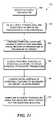
- the step of providing a dimensionally stable hydrogel massincludes the step of selecting a dimensionally stable hydrogel mass in which a length between the lower surface and the distal surface of the dimensionally stable hydrogel mass will ensure that a focal region of the ultrasound transducer is disposed proximate the target.
- the step of providing a dimensionally stable hydrogel massincludes the step of selecting a dimensionally stable hydrogel mass that has a melting point sufficiently high, and an acoustical absorbance sufficiently low to enable the dimensionally stable hydrogel mass to maintain its structural integrity when employed to couple an acoustic transducer to a target, under the following conditions: (a) the transducer is energized for a period ranging from about 1 second to about 100 seconds, and (b) the intensity of the acoustical beam at the focal region of the transducer ranges from about 100 W/cm2 to about 10,000 W/cm2.
- the step of coupling a proximal surface of the dimensionally stable hydrogel mass to an outer surface of the ultrasound transducercan include the step of using a retaining housing to removably couple the dimensionally stable hydrogel mass with the ultrasound transducer.
- the retaining housingsubstantially encompasses each surface of the dimensionally stable hydrogel mass, except for the proximal surface and the outer extent of the distal surface.
- Still another aspect of the present inventionis directed to a method for making a dimensionally stable hydrogel mass to acoustically couple with an ultrasound transducer configured to apply HIFU to a target, wherein the dimensionally stable hydrogel mass includes a proximal surface configured to couple with an ultrasound transducer and a distal surface configured to couple with at least one of a target and a physical boundary separating the target from the ultrasound transducer.
- the methodincludes the steps of providing at least one monomer capable of forming a dimensionally stable hydrogel mass when polymerized and hydrated, providing an agent for inducing polymerization of the at least one monomer, providing a quantity of water sufficient to hydrate the quantity of the at least one monomer that will be polymerized, and providing a mold configured to form a dimensionally stable hydrogel mass to a desired size and shape.
- the dimensionally stable hydrogel massis produced by mixing appropriate quantities of each monomer, the agent for inducing polymerization, and water together to form a mixture, introducing the mixture into the mold, and allowing the mixture to polymerize in the mold. Once polymerization is complete, the dimensionally stable hydrogel mass is removed from the mold.
- the moldincludes reservoir and a mold volume which are in fluid communication.
- the mold volumeconforms to the desired size and shape of the dimensionally stable hydrogel mass to be produced.
- the mixtureis introduced into the mold via the reservoir, until the mold volume is filled with the mixture, and additional mixture is in the reservoir. Polymerization of the mixture in the reservoir is inhibited, while polymerization of the mixture in the mold volume is allowed. The polymerization reduces the volume of the mixture in the mold volume, so that more of the mixture in the reservoir flows into the mold volume and polymerizes.
- the mixture in the reservoir volumeis allowed to polymerize.
- the dimensionally stable hydrogel massis removed from the mold, and any undesired portion of the dimensionally stable hydrogel mass (i.e. the portion corresponding to the reservoir) is removed.
- the step of inhibiting the polymerization of the mixture in the reservoirincludes the step of stirring the mixture in the reservoir.
- the reservoiris disposed above a portion of the mold volume corresponding to the distal surface of the desired dimensionally stable hydrogel mass.
- the reservoircan be shaped to produce a dimensionally stable hydrogel mass whose distal surface is convex, flat, or concave.
- the methodpreferably uses at least one monomer and an agent for inducing polymerization, which have been selected to produce a dimensionally stable hydrogel mass that has a desired melting point and a desired acoustical absorbance, so as to enable the dimensionally stable hydrogel mass to maintain its structural integrity when employed to couple an acoustic transducer to a target under predefined conditions.
- a fluid channelis preferably formed within the dimensionally stable hydrogel being produced.
- the methodcan include the step of adding a medicinal agent to the mixture before the mixture is introduced into the mold, such that the dimensionally stable hydrogel mass produced includes a medicinal agent.
- the medicinal agentcan be added to the dimensionally stable hydrogel mass after it has polymerized.
- FIG. 1(Prior Art) schematically illustrates dimensions and beam characteristics of a 3.5 MHz acoustic transducer that is capable of being used for HIFU therapeutic applications;
- FIG. 2Aschematically illustrates an exemplary shape for hydrogel couplings in accord with the present invention
- FIG. 2Bschematically illustrates how closely the exemplary shape of the hydrogel coupling shown in FIG. 2A corresponds to the focused beam characteristics of the acoustic transducer of FIG. 1 ;
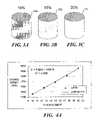
- FIG. 3Aschematically illustrates a polyacrylamide (PA) gel coupler in accord with the present invention, produced using 10% acrylamide monomer;
- PApolyacrylamide
- FIG. 3Bschematically illustrates a PA gel coupler in accord with the present invention, produced using 15% acrylamide monomer
- FIG. 3Cschematically illustrates a PA gel coupler in accord with the present invention, produced using 20% acrylamide monomer
- FIG. 4Ais a graphical representation of sound speed in PA hydrogel couplings versus acrylamide concentration, showing a linear data fit
- FIG. 4Bis a graphical representation of sound speed in PA hydrogel couplings versus acrylamide concentration, showing a polynomial data fit
- FIG. 5Ais a graphical representation of the acoustic impedance of PA hydrogel couplings versus acrylamide concentration, showing a linear data fit;
- FIG. 5Bis a graphical representation of the acoustic impedance of PA hydrogel couplings versus acrylamide concentration, showing a polynomial data fit;
- FIG. 6Ais a graphical representation of the attenuation coefficient of PA hydrogel couplings versus acrylamide concentration, showing a linear data fit
- FIG. 6Bis a graphical representation of the attenuation coefficient of PA hydrogel couplings versus frequency for different acrylamide concentrations, showing a polynomial data fit;
- FIG. 6Cis a graphical representation of the attenuation coefficient of a 15% PA hydrogel coupling versus gel temperature
- FIG. 7schematically illustrates each component of a three-part gel mold with the mold in an unassembled state, wherein the mold is configured to produce a substantially cone shaped hydrogel coupling, in accord with the present invention
- FIG. 8schematically illustrates the three-part gel mold of FIG. 7 in an assembled state
- FIGS. 9A–9Cschematically illustrates the three-part gel mold of FIG. 7 being filled with a mixture that polymerizes to form the solid hydrogel coupling;
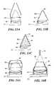
- FIGS. 10A and 10Bschematically illustrate the top portion of the three-part gel mold of FIG. 7 , to show how the shape of the top portion of the mold determines the shape of the distal surface of the hydrogel coupling produced by the mold;
- FIGS. 11A–11Dschematically illustrate how changes to the top portion of the three-part gel mold of FIG. 7 affect the shape of the distal surface of the hydrogel coupling produced by the mold;
- FIG. 12Aschematically illustrates a hydrogel coupling in accord with the present invention, coupled to an acoustic transducer that is mounted on a probe;
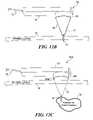
- FIG. 12Bschematically illustrates the hydrogel coupling, acoustic transducer, and probe of FIG. 12A being employed to deliver HIFU to a target location on the dermal layer of a patient;
- FIG. 12Cschematically illustrates the probe and acoustic transducer of FIGS. 12A and 12B , and a different hydrogel coupling, in accord with the present invention, having a length selected so that a focal region of the acoustic transducer extends to a target underneath the dermal layer of the patient, to deliver HIFU to the sub-dermal target;
- FIG. 13Aschematically illustrates an exploded view of a probe including an acoustic transducer, a hydrogel coupling, and a restraining housing;
- FIG. 13Bschematically illustrates the probe of FIG. 13A , with the hydrogel coupling secured to the acoustic transducer by the restraining housing;
- FIG. 13Cschematically illustrates beam characteristics achieved by the probe of FIG. 13B when the acoustic transducer is energized
- FIG. 14Aschematically illustrates an exploded view of the probe of FIG. 13A , a different hydrogel coupling, and a different restraining housing;
- FIG. 14Bschematically illustrates the probe of FIG. 14A with the different hydrogel coupling secured to the acoustic transducer using the different restraining housing;
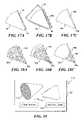
- FIG. 15Aschematically illustrates an acoustic transducer and a hydrogel coupling, in accord with the present invention, the hydrogel coupling having a length that is selected so that a focal region of the acoustic transducer overlaps a desired target, when the outer extent of the distal surface of the hydrogel coupling is brought into contact with a surface overlying the target;
- FIGS. 15B–15Geach schematically illustrates a hydrogel coupling in accord with the present invention, each different hydrogel having a different length, such that an outer extent of the distal surface of each hydrogel coupling is offset from a focal region of an acoustic transducer by a different amount;
- FIG. 16is a representation of a plurality of Schlieren images of ultrasound field produced by the 3.5 MHz spherically concave transducer of FIG. 1 , showing the image when now hydrogel coupling is used in comparison to the images for different length hydrogel couplings;
- FIG. 17Aschematically illustrates a hydrogel coupling and an external fluid channel, wherein the external fluid channel is employed to hydrate the tip of the hydrogel coupling;
- FIG. 17Bschematically illustrates a hydrogel coupling, a restraining housing, and an external fluid channel attached to the restraining housing;
- FIG. 17Cschematically illustrates a hydrogel coupling with an internal fluid channel
- FIG. 18Aschematically illustrates a hydrogel coupling with a medicinal agents dispersed within the hydrogel coupling
- FIG. 18Bschematically illustrates the hydrogel coupling of FIG. 18A responding to an acoustical beam passing through the hydrogel coupling, showing how the acoustical beam drives the medicinal agent out of the hydrogel coupling;
- FIG. 18Cschematically illustrates a hydrogel coupling with medicinal agent disposed substantially adjacent to the tip of the hydrogel coupling, and showing an optional fluid channel used to deliver a medicinal agent to the tip;
- FIG. 19schematically illustrates a kit in accord with the present invention, which includes at least a hydrogel coupling, and may optionally include one or more of a restraining housing, instructions, and coupling gel for coupling the hydrogel coupling with an acoustic transducer;
- FIG. 20is a flowchart of the sequence of logical steps employed to utilize a hydrogel coupling in accord with one aspect of the present invention, wherein the hydrogel coupling must be sufficiently robust not to breakdown or melt in HIFU applications;
- FIG. 21is a flowchart of the sequence of logical steps employed to utilize a hydrogel coupling in accord with another aspect of the present invention, wherein the hydrogel coupling has a length that ensures the focal region of the acoustic transducer is proximate the target;
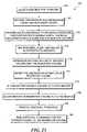
- FIG. 22is a flowchart of the sequence of logical steps employed to produce a hydrogel coupling having a length that ensures the focal region of the acoustic transducer is proximate the target;
- FIG. 23is a flowchart of the sequence of logical steps employed to produce a hydrogel coupling using a mold that has a reservoir and a mold volume, and which accommodates shrinkage of the hydrogel material during polymerization.
- the present inventionrelates to utilizing solid hydrogels as acoustic couplings for clinical applications of ultrasound imaging and therapy, particularly HIFU based therapy.
- Various aspects of the present inventionare disclosed in regard to different embodiments of hydrogel based couplings, methods for using such couplings, and methods for fabricating such couplings.
- hydrogel couplings in accord with the present inventionwere evaluated by using such hydrogel couplings to acoustically couple a known acoustic transducer to a variety of targets.
- the specific acoustic transducer employedwas a prior art HIFU transducer 10 (SU-102-01) obtained from Sonic Concepts (Woodinville, Wash.).
- the single element, spherically concave transducerhas a center frequency of 3.5 MHz. Its aperture diameter and radius of curvature are 35 mm and 55 mm, respectively, providing an f-number of 1.57.
- Field mapping of the focal regionshowed the 6 dB focal width and focal depth to be 1.0 mm and 10.6 mm, respectively.
- the basic beam characteristics of this acoustic transducerare also shown in FIG. 1 .
- the present inventionis not limited to use with the specific transducer employed in the empirical testing. While other acoustic transducers suitable for HIPU applications may have different specifications (i.e. different aperture diameters, different curvatures, different f-numbers, and different focal regions), many acoustic transducers suitable for HIFU application will exhibit a generally conical shaped beam 12 , and a substantially smaller focal region 14 .
- FIG. 2Ashows a hydrogel coupling 16 having a generally conical shape.
- a lower surface 20is preferably configured to couple easily in good acoustic contact with an ultrasound transducer. Coupling is most readily achieved if the shape of proximal surface 20 corresponds to the shape of an outer surface of the transducer. However, a mismatch of shapes is not fatal, if sufficient liquid or gel based coupling media is disposed between the outer surface of the transducer and the proximal surface of hydrogel coupling 16 . As many HIFU transducers exhibit a generally conical shaped beam, hydrogel couplings having similar shapes are particularly well suited for coupling such transducers to targets.
- the dimensions selected for the cone shaped hydrogel couplingsubstantially corresponded to the beam dimensions shown in FIG. 1 .
- a hydrogel coupling configured to couple a transducer having different beam dimensionscan similarly be produced having dimensions substantially corresponding to the beam dimensions of a specific transducer.
- Hydrogel coupling 16thus substantially corresponds to the beam dimensions of a specific transducer, and a distal surface 18 of hydrogel coupling 16 extends into the focal region of the transducer. While the shape of the hydrogel coupling is not required to substantially match the beam dimensions of a transducer in each aspect of the present invention, in at least some embodiments the dimensions of the hydrogel coupling will substantially match the dimensions of the beam from a selected transducer. As will be described in greater detail below, in some aspects of the present invention, the dimensions of the hydrogel coupling are manipulated specifically to achieve a shape differing from the beam dimensions of a transducer for a specific purpose.
- FIG. 2Bclearly illustrates that hydrogel coupling 16 substantially corresponds to the focal characteristics of beam 12 , which is generated by transducer 10 a
- Transducer 10 adiffers from transducer 10 in that it is mounted in a base 15 , whereas a base is not shown in connection with transducer 10 .
- the upper curved surface of a transducercan be accommodated in bases of various sizes and shapes.
- the base used with transducer 10 afacilitates mounting the transducer to a probe, as discussed below.
- hydrogel coupling 16is coupled with transducer 10 a .
- the outer extent of distal surface 18is disposed proximate focal region 14 .
- hydrogel coupling 16must be sufficiently robust to endure HIFU applications without melting or damage that would cause distal surface 18 (disposed proximate the focal region) to fail to maintain acoustic coupling with the tissue of a patient.
- the outer extent or tip of the distal surface of the couplingwill be disposed proximate the focal region. That portion of the coupling will be exposed to temperatures significantly greater than those experienced by couplings used to couple imaging transducers to targets.
- One aspect of the present inventionis directed to a hydrogel coupling wherein the specific hydrogel is selected to ensure that the hydrogel coupling is sufficiently robust for use in HIFU applications.
- the material selectedmust have sufficient transmissivity to avoid overheating as a result of absorbing ultrasound energy. In other words, it is important that the coupling material deliver as much as possible of the HIFU energy to the focal region and not absorb the energy.
- the energy deposited in a coupling medium disposed proximate the focal region of a transducercan be calculated as follows:
- T2 ⁇ ⁇ ⁇ ⁇ ⁇ It ⁇ ⁇ ⁇ c m + T 0 ( 1 )
- Tthe temperature after a time t
- Ithe temporal average intensity
- ttime
- ⁇the absorbance coefficient in Nepers/cm
- ⁇the density of the medium
- c mthe specific heat per unit mass.
- the majority of attenuation(more than 95%) can be attributed to absorbance, and as a result, the absorbance is assumed to be approximately equal to the attenuation.
- the counteracting parametersare thermal convection dissipating energy out of the HIFU focus, and cooling due to blood flow.
- the equationdoes demonstrate that a large temperature increase in the coupling medium can be expected at or near the focus.
- a robust coupling mediummust be able to handle large temperature increases by having a high melting point, as well as having a low attenuation that reduces the temperature increase.
- hydrogels used to produce hydrogel couplingsare selected to ensure that when the hydrogel coupling is used in conjunction with an acoustic transducer in accord with certain parameters, and with a portion of the hydrogel coupling disposed proximate the focal region of the transducer, the dimensionally stable hydrogel mass forming the coupling has a melting point that is sufficiently high, and an acoustical absorbance that is sufficiently low to enable the dimensionally stable hydrogel mass to maintain its structural integrity.
- the parametersare: (a) the transducer is energized for a period ranging from about 1 second to about 100 seconds; and, (b) the intensity of the acoustical beam generated by the transducer ranges from about 100 W/cm 2 to about 10,000 W/cm 2 .
- PA hydrogelscan have very high WC, ranging from 70% to more than 90% water by weight and can be prepared relatively easily and quickly at room temperature.
- the mechanical properties of PA hydrogels, and therefore their acoustic properties,can be varied in a straightforward manner simply by changing the overall concentration of acrylamide monomer in the material.
- PAhas been used for a variety of biomedical applications and has been shown in many studies to have very good biocompatibility.
- PAblood-contacting device
- a recent clinical study that investigated the use of a PA-based blood filtration techniqueshowed the material to have good blood-compatibility, with no signs of hemolysis or blood clotting.
- Moderate material costs and straightforward manufacturing methodsenable inexpensive, custom-designed, disposable HIFU coupling devices to be made from PA gels.
- FIGS. 3A–3Cschematically represent three PA gel test plugs fabricated in order to gain empirical data about hydrogel couplings suitable for HIFU applications. Each sample has a diameter of 2.5 cm and a height of approximately 3 cm. Stiffness and transparency increase with acrylamide concentration. Note that plug 22 a was formed using acrylamide monomer at a concentration of 10%, and is slightly opaque as indicated by the shading in this plug. Plug 22 b was formed using acrylamide monomer at a concentration of 15%, and is more transparent, as indicated by the diminished shading in plug 22 b . Plug 22 c was formed using acrylamide monomer at a concentration of 20%, and is substantially transparent, as indicated by the lack of shading. The procedure for producing the gel plugs is explained in detail below. This procedure was also employed for producing generally cone-shaped PA hydrogel couplings, as well as PA hydrogel couplings having other shapes. Substantially transparent couplings have the advantage of enabling a clinician to see through the coupling, to better view the target area.
- a cross-linking agentis used to hold the long polymer chains together in a matrix.
- Bisacrylamidealso known as N,N′-methylenebis(acrylamide)
- the bisacrylamide moleculeconsists of two acrylamide residues joined at their amide groups by a methyl group. The two acrylamide residues participate in the polymerization reaction as though they were two independent monomers.
- this buffering agentis used to adjust the pH of the gel to pH 8.
- the pH of the mediumis important in determining the charges on the biological molecules used.
- the pH of the solutionmay affect the protonation state of the —NH 2 groups of the acrylamide monomers. With respect to the present invention, the influence of pH was not investigated, but was simply kept constant for each gel. Because the production of PA electrophoresis gels is well known, the same pH level was employed in making PA for use in the present invention.
- the buffer solution employedwas Trizma base, also called Tris(hydroxymethyl)aminomethane, and Trizma hydrochloride, also called Tris(hydroxymethyl)aminomethane hydrochloride.
- Ammonium persulfatewas employed as an initiator for polymerization, since it is a source of free radicals. In solution, APS forms the persulfate ion, S 2 O 8 2 ⁇ . This common, water-soluble initiator is one of the strongest chemical oxidizing agents known.
- TEMEDalso known as N,N,N′,N′-Tetramethylethylenediamine catalyzes the radical formation process.
- APS and TEMEDform a redox system, where APS is the oxidizing agent and TEMED is the reducing agent.
- TEMEDis the reducing agent.
- the APS-TEMED redox systemis a type of thermal initiator. For a 15% -weight in volume PA gel, the maximum temperature during polymerization was about 61° C. The proportion of APS-TEMED initiator to total solution determines the rate at which polymerization occurs. Polymerization rate increases with an increasing proportion of the initiator. In addition, reaction rate and temperature increase with the concentration of acrylamide in solution. Thus, higher-concentration gels tend to polymerize at a faster rate and reach higher temperatures during polymerization than lower-concentration gels.
- the physical properties of PAvary according to the concentration of acrylamide monomer in the gel.
- Acrylamide concentrations used in gathering empirical data relating to the present inventionranged from 10% to 20% weight in volume (w/v). The percent concentration was determined by the ratio of the mass of total acrylamide to the volume of pre-polymerized solution.
- An aqueous solution of 40% w/v acrylamide with a 19:1 monomer to cross-linker ratio(LIQUI-GEL; ICN Biomedicals, Aurora, Ohio) was used to prepare the gels.
- the hydrogelswere formed in solution by the free radical, chain-reaction polymerization process noted above. The initiated solution was transferred to either a cylindrical mold (see FIGS.
- FIGS. 7 and 8a substantially cone-shaped mold
- the cylindrical moldwas primarily employed to produce plugs for material testing and characterization, while the cone shaped mold was employed to produce hydrogel couplings that were tested with the acoustic transducer described in connection with FIG. 1 .
- the moldwas kept upright, so that the gel's top face formed parallel to the bottom face.
- Each gel plugwas allowed to polymerize for about 25 to 30 minutes.
- the resulting cylindrical gel plugswere 2.5 cm in diameter and approximately 3 cm in height ( FIGS. 3A–3C ).
- hydrogelsA difficulty associated with using hydrogels is that they dehydrate when left exposed to ambient air, and swell when placed in water due to increased absorption of the water. Therefore, the gels were either tested within one hour after polymerization, or stored in vacuum-sealed, plastic bags for later use.
- WCWater content
- densitywas measured for gels with varying acrylamide concentrations. WC was determined for acrylamide concentrations of 10%, 15%, and 20% w/v. Six gel samples were tested for each concentration. Density was measured for concentrations of 10%, 12.5%, 15%, 17.5%, and 20% w/v. Seven gel samples were tested for each concentration.
- the WCwas determined by comparing the mass of the hydrated gel immediately after polymerization, m h , to the mass of the dehydrated gel, m d .
- Water contentwas calculated using the following formula:
- the density, ⁇ of the gel immediately after polymerizationwas calculated by dividing the mass of the gel by its volume. Mass was measured with an electronic scale, and volume was measured using a water displacement technique.
- the WC of PAdecreased from 87% to 76% as a linear function of increasing acrylamide concentration.
- the density of the gelwas found to be slightly greater than the density of water, increasing from 1.02 to 1.05 g/ml as a linear function of increasing acrylamide concentration.
- a pulse transmission techniquewas used to measure the attenuation coefficient and speed of sound in the PA samples. Calculations were based on the well known substitution method, where two acoustic paths are compared. The sample path contained the gel sample with approximately two centimeters of water on either side, and the reference path contained only water. The attenuation coefficient was measured at frequencies of 1 MHz to 5 MHz.
- the acoustic properties of PAincreased as linear functions of increasing acrylamide concentration. Sound speed ranged from 1546 to 1595 m/s for 10% and 20% w/v gels, respectively ( FIG. 4A ). Acoustic impedance ranged from 1.58 to 1.68 Mrayl ( FIG. 5A ). Attenuation ranged from 0.08 to 0.14 dB/cm at 1 MHz ( FIG. 6A ). Linear regression showed that the rate of increase in attenuation coefficient with concentration was larger at higher frequencies. A plot of attenuation coefficient versus frequency showed that attenuation was not a linear function of frequency ( FIG. 6B ).
- the thermal conductivity, k(W/m/° C.), and specific heat capacity, Cp(J/kg/° C.), of PAwere measured by monitoring the thermal dissipation of a heat impulse.
- a nickel-chromium heating wirewas pulled taut through the center of a custom-made measurement cell.
- the initiated PA solutionwas poured into the measurement cell (approximately a cube with 5 cm edges) and allowed to polymerize into the hydrogel.
- Four needle T-type thermocouples(Omega Engineering Inc., Stamford, Conn.) were inserted into the gel parallel to the heating wire. The thermocouples were placed at different radial distances from the wire, ranging from 4 mm to 11 mm.
- thermocouple temperatureswere measured using an ultrasound imaging system (a model HDI 1000TM from ATL Corp., Bothell, Wash.).
- a LabVIEWTMNational Instruments, Austin, Tex. program controlled the length of the current pulse delivered to the heating wire, and recorded the four thermocouple temperatures over time.
- T(° C.)was the temperature elevation from ambient at some radial distance, r(m), from the wire; t(s) was the time after heating at which the measurement was made; Q(J) was the total deposited heat (J); L(m) was wire length; ⁇ (kg/m 3 ) was the density of the gel; and ⁇ (m 2 /s) was the thermal diffusivity of the gel. This equation assumes that the time until measurement was significantly larger than the heating time, and that the diameter of the wire is negligible.
- Thermal propertieswere measured for three different acrylamide concentrations: 10%, 15%, and 20% w/v. Heat was applied for 5s, which resulted in a temperature rise of about 1° C. at 4 mm from the wire. Ln(Tt) versus r 2 /t was graphed for each of the four thermocouple positions. By fitting a line to the data, the slope and intercept were used to calculate C p and k. Two independent experiments were performed for each acrylamide concentration.
- the thermal conductivity and specific heat capacitydid not vary measurably with acrylamide concentration over the range tested.
- E OverallPower efficiency was measured to determine the effectiveness of the PA coupler in delivering focused ultrasound into water.
- E OverallPower efficiency of the transducer-coupler device was defined as the ratio of output acoustic power delivered to a water bath, to input electrical power supplied to the transducer.
- E Transducerwas determined by measuring output acoustic power for the transducer without any coupler attached. The efficiency of the coupler could then be calculated from Equation 3. A test was performed to determine how acrylamide concentration affected the power efficiency of the device.
- E Coupler Theoryexp( ⁇ 2 ⁇ d ) (5) where ⁇ acute over ( ⁇ ) ⁇ (nepers/cm) was the measured attenuation coefficient of the gel at 3.5 MHz, and d(5.2 cm) was the length of the gel. For this calculation, it was assumed that loss of acoustic power was due only to attenuation in the gel coupler. Attenuation due to water was assumed to be negligible.
- Table 2lists the measured and theoretical power efficiency for the different couplers.
- the transducer efficiencywas measured at 55.8%. Attaching the 5.2 cm gel cone to the transducer dropped the overall efficiency to between 22.4% and 28.6%, for 20% and 10% acrylamide concentrations, respectively. Normalizing the overall efficiency to the transducer efficiency showed the gel cones to have coupler efficiencies from 40.1% to 51.3%. For comparison, the coupler efficiency of the water-filled cone was measured to be 65.3%. The measured coupler efficiency of the gel cone was 14% to 23% less than its calculated theoretical efficiency.
- the attenuation coefficient used for PA at 3.5 MHzwas calculated from polynomials fit to the measured attenuation data, and was found to be 0.029, 0.046, and 0.059-nepers/cm, for 10%, 15%, and 20% acrylamide, respectively.
- the favorable acoustic properties of PAmake the material a good coupling medium for applications of both therapeutic and diagnostic ultrasound.
- the gelis a homogeneous material that consists mostly of water. It has low attenuation, with sound speed and acoustic impedance similar to that of tissue. Due to the gel's ideal impedance, minimal reflections will occur at the gel-tissue interface.
- An advantage of the PA couplingis that its acoustic properties vary linearly with acrylamide concentration. Acoustic characterization of the material is, therefore, a straightforward process, if gel concentration is known, making it relatively easy to match the impedance of specific tissue in a patient's body.
- a PA couplerhas several properties that make it desirable for HIFU applications.
- the acoustic propertiesvary linearly with acrylamide concentration, which allows for straightforward modification of the gel's acoustic and impedance characteristics.
- the PA coupler's acoustic impedancecan be matched to a particular tissue simply by varying the acrylamide concentration.
- reducing impedance mismatch at the gel-tissue interfacecan diminish the occurrence of skin burns caused by reflections and standing waves.
- Matching sound speed of a PA coupling to a specific tissue typecan reduce adverse effects caused by refraction of the ultrasound beam at the gel-tissue interface. In some HIFU applications, this issue may be of substantial importance, since a shift in the position of the focus can result in undesirable damage to surrounding normal tissue.
- PA couplingsDue to its low attenuation, PA couplings have acceptable power transfer efficiency. Since efficiency decreases with increasing coupler length, it might be advantageous to use transducers with short focal distances for superficial HIFU treatments.
- Hydrogels in generalhave the advantages associated with being a solid coupling material. Unlike water-filled couplers, there are no problems with containment and leakage of the hydrogel coupling medium.
- couplingscan be formed to fit to a specific HIFU transducer. Their shape and size can also be modified for a particular application. For transcutaneous applications, the depth of the focus below the tissue interface can be adjusted by using couplings with different lengths, as described in detail below. For intraoperative hemostasis applications, the shape and height of the cone tip can be varied to achieve more effective treatments. Modifying the tip shape is done by selecting an appropriate mold, as described below.
- the couplingneed not be permanently attached to a HIFU transducer. Unlike prior art aluminum couplers, which were held to the PZT element by epoxy, the coupling can be temporarily attached with a thin layer of water or sonography gel and readily replaced with a different coupling.
- the disposable nature of the couplingis ideal for HIFU applications in which the focus is near the distal tip of the coupling. While a gel may ultimately sustain some HIFU or mechanically related damage to its tip, this damage does not permanently impair the transducer for farther use, since a new coupling can readily replace the current one.
- PA hydrogelshave been empirically tested and proven capable of being used for HIFU applications, it is expected that other hydrogel materials, and or mixtures of different hydrogels will be identified as being sufficiently robust to be employed as a coupler for HIFU applications.
- poly(2-hydroxyethyl methacrylate), or pHEMAis likely to be a useful hydrogel for HIFU applications.
- the three part moldincludes a base portion 32 , a middle portion 34 , and a top portion 36 .
- Base portion 32is configured to match the concave outer surface of the transducer, and thus includes a concave surface 40 .
- Base portion 32can be modified to achieve a mold configured to produce a hydrogel coupling for a different transducer having a distal surface with a different shape or dimension.
- the proximal surface of the hydrogel coupling produced by mold 30corresponds to the shape of the outer surface of the transducer with which the hydrogel mass is to be used.
- FIG. 7shows a hydrogel coupling 38 seated in base portion 32 .
- Middle portion 34is substantially cone shaped, to match the focal characteristics of the exemplary transducer, as shown in FIGS. 1 and 2B , discussed above. Of course, other shapes can be employed, as desired.
- Top portion 36includes a tip molding portion 42 , which as described in detail below can be modified to achieve a desired shape for the outer extent or tip of the distal surface of a hydrogel coupling produced using mold 30 .
- Top portion 36also includes a drip channel 44 coupling a reservoir 46 in fluid communication with a mold volume 48 . Mold volume 48 is defined by base portion 32 , middle portion 34 and top portion 36 .
- FIGS. 9A–9CThe function of reservoir 46 is illustrated in FIGS. 9A–9C .
- a liquid mixturesuch as the acrylamide monomer based mixture disclosed above
- FIG. 9Bthe mixture within the mold volume is allowed to polymerize, while polymerization of the mixture in the reservoir is inhibited.
- An exemplary technique to prevent polymerizationis agitating or stirring the mixture in the reservoir.
- agitating or stirring the mixture in the reservoirmay be appropriate. For example, some polymer reactions are initiated by illuminating with light of an appropriate wavelength (dental polymers used to replace mercury amalgams are an example).
- inhibiting polymerizationmight involve preventing light of that wavelength from reaching the mixture in the reservoir, while light is applied to the mixture in the mold volume.
- PA hydrogel described in detail aboverepresents an exemplary hydrogel, mold 30 , and variants of mold 30 , can be used to form other hydrogel materials into acoustic couplings, and thus the technique for inhibiting the polymerization in the reservoir will be dictated by the initiator used to induce polymerization in the specific reaction and material employed.
- the mixture in the reservoiris allowed to polymerize.
- the moldis taken apart, and the portion of the hydrogel within the reservoir (and within the drip channel coupling the reservoir to the mold volume) can be trimmed away.
- mold 30performed admirably for laboratory purposes, mass production of hydrogel couplings will likely be achieved using molds specifically adapted for high speed production.
- the present inventionis not limited to manufacture specifically using mold 30 , or even to three part molds.
- FIGS. 10A–11Dprovide details on how modifying top portion 36 can enable hydrogel couplings having distal surfaces of different configurations to be achieved.
- the distal surface of the hydrogel couplingshould closely conform to the surface of the target or boundary, respectively. While coupling gels can be used to fill any gaps, closely matched surfaces enhance coupling and ease of use.
- top portion 36comprises an outer ring 36 a and an inner portion 36 b .
- Inner portion 36 bincludes the reservoir and the drip channel described above (reference numbers omitted to simplify the Figure, see FIG. 8 ).
- a surface 54 adetermines the shape of the tip of the distal surface of the hydrogel coupling produced.
- ring 36 a and middle portion 34can rotatably couple together using threads in an area 62 .
- the dimensions of ring 36 a and middle portion 34can be configured at area 62 such that ring 36 a is press fit onto middle portion 34 securely enough so that the mold does not come apart while molding the PA material, but loosely enough so that the ring can be removed after the mold is used, to disassemble the mold.
- ring 36 a and inner portion 36 bare notched at area 64 , to enable inner portion 36 b to be held securely in position, as shown in FIG. 10B .
- FIGS. 11A–11Dillustrate inner portions of different shapes, and the tip of the distal surface of a hydrogel coupling that is achieved using that inner portion.
- inner portion 36 bcan be employed to produce a hydrogel coupling having a tip on distal surface 54 b that is a full convex, corresponding to a full concave surface 54 a on the bottom of inner portion 36 b .
- a useful radius of curvature for surface 54 ais about 4.8 mm.
- inner portion 36 ccan be employed to produce a hydrogel coupling having a tip on distal surface 56 b that is a short convex, conforming to a short concave surface 56 a on the bottom of inner portion 36 c .
- a useful radius of curvature for concave surface 56 ais 7.3 mm.
- inner portion 36 dcan be employed to produce a hydrogel coupling having a tip on distal surface 58 b that is flat, conforming to a flat 58 a
- inner portion 36 ecan be employed to produce a hydrogel coupling having a tip on distal surface 60 b that is concave, conforming to a convex surface 60 a
- a useful radius of curvature for convex surface 60 ais 7.3 mm.
- FIG. 12Aillustrates an exemplary use of hydrogel couplings in accord with the present invention.
- a conical hydrogel coupling 66is attached to an acoustic transducer 68 , mounted to a handle 70 .
- a lead 72couples the transducer to a power supply 74 .
- probe 65is being used to apply HIFU to a target proximate a dermal layer 76 of a patient (not otherwise shown).
- Focal region 14is proximate to (within) the dermal layer.
- the distal surface of coupling 66is disposed proximate to the focal region of the transducer.
- probe 65could be used inside a patient's body, inserted via a body cavity or incision, and is not limited to external use.
- the significance of probe 65is that the focal region of the transducer is disposed proximate to the distal surface of the hydrogel coupling so that the tip of the hydrogel coupling is immediately adjacent to the treatment site.
- the HIFUcan be easily aimed by observing the tip of the distal surface of the hydrogel coupling.
- a probe 65 a shown in FIG. 12Cis different, in that the distal surface of a hydrogel coupling 66 a is not disposed immediately adjacent to or proximate to the focal region of the transducer.
- Hydrogel coupling 66 ais significantly shorter, such that when the tip of the hydrogel coupling lies against the dermal layer of the patient, the focal region of the transducer is within a subcutaneous target 78 . Selecting an even shorter hydrogel coupling would enable the focal region to penetrate further below the dermal layer and deeper into the subcutaneous target, while selecting a longer hydrogel coupling will bring the focal region closer to the dermal layer.
- a hydrogel coupling of an appropriate lengthcan be selected, so as to ensure that the focal region of the transducer is disposed proximate to the desired target.
- less robust hydrogelscan be employed, because the distal surface is no longer proximate to the focal region, where the highest temperatures are likely to be encountered.
- FIGS. 13A–13Cillustrate how a restraining housing 80 a can be used to removably secure hydrogel coupling 66 to transducer 68 .
- FIG. 13Ais an exploded view illustrating how restraining housing 80 a fits over hydrogel coupling 66 .
- the restraining housinghas been secured to transducer 68 (or handle 70 ), thereby mounting hydrogel coupling 66 in place.
- Restraining housing 80 ais open at its conical end, so that a tip of distal surface 82 of the hydrogel coupling is exposed and extends beyond the restraining housing.
- FIG. 13Cshows transducer 68 being energized, resulting in acoustical waves 84 . Note that the focal region of the transducer is proximate to the upper extent of distal surface 82 of the hydrogel coupling.
- FIGS. 14A and 14Bshow a shorter restraining housing 80 b being used to couple a shorter hydrogel coupling 86 to the same transducer.
- FIG. 14Ais an exploded view illustrating how restraining housing 80 b fits over hydrogel coupling 86
- FIG. 14Bis an assembled view.
- FIG. 14Balso includes beam dimension 12 and focal region 14 , illustrating that a distal surface 88 of hydrogel coupling 86 is not disposed proximate to the focal region.
- FIGS. 15A–15Gfurther illustrate how the length of a hydrogel coupling can be selected to enable the focal region to be disposed adjacent to a target.
- a hydrogel coupling 90is shown positioned over transducer 68 .
- Coupling 90has a length 92 .
- the position of the focal region relative to a distal surface of the hydrogel couplingcan be varied. Longer hydrogel couplings (e.g., hydrogel coupling 94 e ) will result in distal surfaces of the couplings being disposed closer to the focal region.
- Shorter couplings(e.g., coupling 94 a ) will result in distal surfaces of the hydrogel couplings being disposed farther away from the focal region. As shown in FIG. 12C , the shorter the coupling, the farther away the focal region will be from the distal surface of the coupling, which will be brought into contact with the surface of intervening tissue.
- FIG. 16illustrates Schlieren images obtained using hydrogel couplings of varying lengths.
- Schlieren imagingwas used to visualize the ultrasound field emitted from the HIFU transducer with the hydrogel coupler attached, and to determine if the gel coupler was in any way distorting the HIFU field.
- Four 15% gel cones of different shapeswere tested: a 2 cm truncated cone; a 3 cm truncated cone; a full-length cone with flat tip; and a full-length gel cone with convex rounded tip.
- a collimated beam of lightpassed through an optically transparent tank containing degassed water. The HIFU beam was directed into the water tank, perpendicular to the light beam axis. The light leaving the tank was focused and filtered, and the image was displayed on a screen.
- FIGS. 17A–17Cillustrate several structures that can be used to achieve such hydration.
- FIG. 17A–17Cillustrate several structures that can be used to achieve such hydration.
- a fluid channel 98is coupled with a water supply (not shown), and the other end of the fluid channel is disposed adjacent to a tip 95 of the distal surface of hydrogel 96 .
- a fluid channel 98 ais attached to a restraining housing 100 and is coupled with a water supply (not shown); the other end of the fluid channel is disposed adjacent to tip 95 of the distal surface of hydrogel 96 .
- a fluid channel 102is disposed within hydrogel coupling 96 a . Fluid channel 102 is coupled with a water supply (not shown), and the other end of the fluid channel is disposed adjacent to a tip 95 a of the distal surface of hydrogel 96 a , to enable the surface to be hydrated.
- a unique advantage of using a hydrogelis the possibility of introducing medication, such as antibiotics, into the hydrogel coupling, and to administer such medications where the hydrogel coupling contacts the tissue of a patient.
- the hydrogel couplercan be used to transfer antibiotics, in addition to ultrasound, into the treatment site.
- FIGS. 18A–18Cillustrate several structures that can be used to achieve such medication.
- a hydrogel coupling 96 bhas a medicinal agent 104 distributed throughout the hydrogel. The agent can be added after the hydrogel is produced.
- Hydrogelsinclude many channels within the hydrogel where such medicinal agents can be absorbed and stored. It is expected that if the polymerization is not detrimental to the medicinal agent, the medicine can be added before the hydrogel is produced.
- energizing a transducer coupled to the hydrogelcauses some of the medicinal agent to be “pushed out” of tip 95 b of the distal surface of the hydrogel coupling.
- the effect of the therapeutic agentcould be either synergistic with, or independent of HIFU.
- the therapeutic outcomecan either be enhanced exponentially, or arithmetically, depending on the choice of the therapeutic agent and the HIFU dose.
- medicinal agent 104has been distributed proximate to a tip 95 c of the distal surface, rather than throughout hydrogel coupling 96 c .
- a fluid channel 98 ais shown as an optional element and can be used to hydrate tip 95 c of the distal surface of hydrogel coupling 96 c , or even to deliver additional medicinal agents. If desired, fluid channel 98 a could be used as the sole method of delivering a medicinal agent.
- Kit 110containing components to be used for acoustically coupling an ultrasound transducer with a target.
- Kit 110includes at least a hydrogel coupling 112 , having a proximal surface configured to be disposed adjacent to an ultrasound transducer, and a distal surface configured to acoustically couple with at least one of a target and a boundary associated with the target.
- the kitalso includes at least a sealed package 122 configured to maintain the hydrogel coupling in a hydrated condition until removed from the sealed package in preparation for use.
- the sealed packagecan be hermetically sealed and/or vacuum-sealed to maintain the contents of the package in a sterile state and avoid loss of hydration of the hydrogel coupler.
- kit 110includes instructions 118 for using the hydrogel coupling to couple an ultrasound transducer with a target, to facilitate an application of HIFU therapy.
- the instructionsmay also inform users how to maintain the distal surface of the dimensionally stable hydrogel coupling in a hydrated condition.
- coupling gel 116is a semisolid or fluidic coupling medium used to enhance an acoustic coupling of the proximal surface of the hydrogel coupling to an outer surface of an ultrasound transducer that is used to administer the HIFU therapy.
- a retaining housing 114configured to removably couple the hydrogel coupling with an ultrasound transducer.
- kits containing different length hydrogel couplerswill preferably be available.
- FIGS. 20–23are flow charts illustrating sequences of logical steps employed in carrying out the present invention.
- FIG. 20illustrates the steps for using a hydrogel coupling sufficiently robust to withstand the ultrasound intensities to be employed;
- FIG. 21illustrates the steps for ensuring that a focal region of a transducer is proximate a target;
- FIG. 22illustrates the steps for making a hydrogel coupling configured to ensure that a focal region of a transducer is proximate a target;
- FIG. 23illustrates the steps for producing a hydrogel that accommodates for shrinkage during polymerization.
- a flow chart 120begins in a block 122 , in which a specific acoustic transducer is selected.
- a block 124an input power level and a duration for energizing the ultrasound transducer are selected.
- a block 126refers to providing a hydrogel coupling that is capable of maintaining its structural integrity when used to couple the ultrasound transducer with at least one of the target and a physical boundary associated with the target under the input power level and duration selected.
- the hydrogel coupling providedhas a length that will ensure that a focal region of the ultrasound transducer is disposed proximate the target.
- the proximal surface of the hydrogel couplingis coupled with an outer surface of the ultrasound transducer
- the distal surface of the hydrogel couplingis coupled with at least one of the target and a physical boundary separating the target from the distal surface of the hydrogel coupling.
- a restraining housingcan be used to secure the hydrogel coupling.
- the ultrasound transduceris energized at the selected input power level and duration.
- Additional stepscan include hydrating the distal surface of the dimensionally stable hydrogel mass, to prevent damage to the tip of the distal surface of the dimensionally stable hydrogel mass by the HIFU, and/or delivering a medicinal agent to at least one of the target and the physical boundary, after coupling the distal surface of the dimensionally stable hydrogel mass to at least one of the target and the physical boundary.
- a flow chart 134begins in a block 136 , where a specific ultrasound transducer to be employed is selected.
- an input power level and a durationare selected to energize the ultrasound transducer.
- a block 140indicates that a hydrogel coupling is provided having a length that will ensure that a focal region of the ultrasound transducer is disposed proximate to the target.
- the proximal surface of the hydrogel couplingis coupled with an outer surface of the ultrasound transducer
- the distal surface of the hydrogel couplingis coupled with at least one of the target and a physical boundary separating the target from the distal surface of the hydrogel coupling.
- a restraining housingcan be used to secure the hydrogel coupling.
- the ultrasound transduceris energized at the selected input power level and duration.
- Flow chart 148 of FIG. 22illustrates the steps involved in producing a hydrogel coupling having a length that will ensure a focal region of a specific ultrasound transducer is disposed proximate to the target.
- the monomer, or mixture of monomersare selected from which the hydrogel will be produced.
- acrylamide monomerscan be beneficially employed.
- the inventionis not so limited, and other monomer(s) can alternatively be employed.
- an agentis provided for inducing polymerization of the at least one monomer, providing a quantity of water sufficient to hydrate the quantity of the selected monomer(s).
- a moldconfigured to form a hydrogel coupling having the desired size and shape is provided.
- the moldis configured to produce a hydrogel coupling having a length that ensures a focal region of a specific ultrasound transducer is disposed proximate to the target, generally as described above.
- the monomer, agent, and waterare mixed together in the appropriate amounts. Those of ordinary skill in the art will recognize that many different components for producing hydrogels are known.
- the mixtureis introduced into the mold.
- the mixtureis allowed to polymerize, and in a block 162 , the hydrogel coupling is removed from the mold.
- a flow chart 164illustrates the logical steps for producing a hydrogel coupling using a mold with a reservoir to accommodate shrinkage.
- the monomeris selected, and in a block 168 , an agent for inducing polymerization of the monomer, and water, are provided.
- a moldconfigured to form a hydrogel coupling having the desired size and shape is provided.
- the moldincludes both a mold volume corresponding to the size and shape of the desired hydrogel coupling, and a reservoir in fluid communication with the mold volume.
- a block 172the monomer, the agent, and water are mixed together in appropriate amounts.
- the mixtureis introduced into the mold.
- the mixture in the reservoiris inhibited from polymerization, while in a block 178 the mixture in the mold volume is allowed to polymerize.
- the mixture in the reservoiris allowed to polymerize, as indicated in block 180 .
- the hydrogel couplingis removed from the mold, and the hydrogel coupling is trimmed in a block 184 , to remove the portion corresponding to the reservoir portion and interconnection to the mold.
- hydrogelsare dimensionally stable, solid appearing materials, in sharp contrast to the semi-solid, paste-like coupling gels frequently used to couple imaging transducers to tissue.
- dimensionally stable hydrogel masshas been employed to emphasize this property.
Landscapes
- Health & Medical Sciences (AREA)
- Life Sciences & Earth Sciences (AREA)
- Animal Behavior & Ethology (AREA)
- Veterinary Medicine (AREA)
- Public Health (AREA)
- General Health & Medical Sciences (AREA)
- Nuclear Medicine, Radiotherapy & Molecular Imaging (AREA)
- Radiology & Medical Imaging (AREA)
- Physics & Mathematics (AREA)
- Chemical & Material Sciences (AREA)
- Epidemiology (AREA)
- Biomedical Technology (AREA)
- Engineering & Computer Science (AREA)
- Acoustics & Sound (AREA)
- Pharmacology & Pharmacy (AREA)
- Medicinal Chemistry (AREA)
- Dispersion Chemistry (AREA)
- Biophysics (AREA)
- Pathology (AREA)
- Heart & Thoracic Surgery (AREA)
- Medical Informatics (AREA)
- Molecular Biology (AREA)
- Surgery (AREA)
- Organic Chemistry (AREA)
- General Chemical & Material Sciences (AREA)
- Chemical Kinetics & Catalysis (AREA)
- Ultra Sonic Daignosis Equipment (AREA)
- Medicines That Contain Protein Lipid Enzymes And Other Medicines (AREA)
- Surgical Instruments (AREA)
Abstract
Description
where T is the temperature after a time t, T0is the temperature at the start of HIFU application (t=0), I is the temporal average intensity, t is time, α is the absorbance coefficient in Nepers/cm, ρ is the density of the medium, and cmis the specific heat per unit mass. The majority of attenuation (more than 95%) can be attributed to absorbance, and as a result, the absorbance is assumed to be approximately equal to the attenuation.
- HIFU intensity, I, on the order of 1000 W/cm2
- HIFU application time, t, on the order of 100 seconds
- Density, ρ, on the order of 1 g/ml
- Specific heat per unit mass, cmis, on the order of 6.5 J/g for PA
- Attenuation coefficient, α, on the order of 0.035 Np/cm, at 3 MHz for PA
Therefore, the temperature rise determined from the above equation is:
T−T0≈1000° C.
| TABLE 1 | |||||
| Acryl. | WC(%) | ρ(g/cm3) | c(m/s) | Z(Mrayl) | α(dB/cm) N = 7 |
| Conc. | N = 6 | N = 7 | N = 7 | N = 7 | 1 | 2 | 3 | 4 | 5 |
| 10% | 87.0 +/− | 1.024 +/− | 546 +/− | 1.583 +/− | 0.077 +/− | 0.115 +/− | 0.206 +/− | 0.300 +/− | 0.437 +/− |
| 0.8 | 0.006 | 2 | 0.008 | 0.039 | 0.033 | 0.031 | 0.037 | 0.058 | |
| 12.5% | — | 1.031 +/− | 558 +/− | 1.607 +/− | 0.099 +/− | 0.179 +/− | 0.259 +/− | 0.386 +/− | 0.523 +/− |
| 0.005 | 2 | 0.008 | 0.027 | 0.043 | 0.043 | 0.037 | 0.051 | ||
| 15% | 81.6 +/− | 1.038 +/− | 568 +/− | 1.628 +/− | 0.121 +/− | 0.185 +/− | 0.331 +/− | 0.495 +/− | 0.698 +/− |
| 1.0 | 0.004 | 2 | 0.005 | 0.027 | 0.042 | 0.037 | 0.042 | 0.112 | |
| 17.5% | — | 1.043 +/− | 582 +/− | 1.649 +/− | 0.119 +/− | 0.249 +/− | 0.376 +/− | 0.540 +/− | 0.760 +/− |
| 0.005 | 2 | 0.009 | 0.051 | 0.036 | 0.033 | 0.036 | 0.029 | ||
| 20% | 76.0 +/− | 1.052 +/− | 595 +/− | 1.679 +/− | 0.142 +/− | 0.236 +/− | 0.413 +/− | 0.647 +/− | 0.873 +/− |
| 1.1 | 0.003 | 2 | 0.004 | 0.020 | 0.047 | 0.046 | 0.066 | 0.041 | |
where T(° C.) was the temperature elevation from ambient at some radial distance, r(m), from the wire; t(s) was the time after heating at which the measurement was made; Q(J) was the total deposited heat (J); L(m) was wire length; ρ (kg/m3) was the density of the gel; and χ (m2/s) was the thermal diffusivity of the gel. This equation assumes that the time until measurement was significantly larger than the heating time, and that the diameter of the wire is negligible.
EOverall=ETransducer×ECoupler (4)
where ETransducerwas the transducer efficiency, and ECouplerwas the coupler efficiency. ETransducerwas determined by measuring output acoustic power for the transducer without any coupler attached. The efficiency of the coupler could then be calculated from
ECoupler. Theory=exp(−2αd) (5)
where {acute over (α)} (nepers/cm) was the measured attenuation coefficient of the gel at 3.5 MHz, and d(5.2 cm) was the length of the gel. For this calculation, it was assumed that loss of acoustic power was due only to attenuation in the gel coupler. Attenuation due to water was assumed to be negligible.
| TABLE 2 | |||
| Measured | Measured | Theoretical | |
| Coupler | Overall | Coupler | Coupler |
| Type | Efficiency (%) | Efficiency (%) | Efficiency (%) |
| No Coupler | 55.8 | 100 | 100 |
| Water-Filled Cone | 36.4 | 65.3 | 100 |
| 10% Acryl. 5.2 cm | 28.6 | 51.3 | 74.2 |
| 15% Acryl. 5.2 cm | 26.3 | 47.3 | 61.7 |
| 20% Acryl. 5.2 cm | 22.4 | 40.1 | 53.8 |
Beneficial Properties of PA Hydrogel Couplings
Claims (45)
Priority Applications (2)
| Application Number | Priority Date | Filing Date | Title |
|---|---|---|---|
| US10/449,819US7070565B2 (en) | 2002-05-30 | 2003-05-30 | Solid hydrogel coupling for ultrasound imaging and therapy |
| US11/369,281US20060184074A1 (en) | 2002-05-30 | 2006-03-07 | Solid hydrogel coupling for ultrasound imaging and therapy |
Applications Claiming Priority (2)
| Application Number | Priority Date | Filing Date | Title |
|---|---|---|---|
| US38456602P | 2002-05-30 | 2002-05-30 | |
| US10/449,819US7070565B2 (en) | 2002-05-30 | 2003-05-30 | Solid hydrogel coupling for ultrasound imaging and therapy |
Related Child Applications (1)
| Application Number | Title | Priority Date | Filing Date |
|---|---|---|---|
| US11/369,281ContinuationUS20060184074A1 (en) | 2002-05-30 | 2006-03-07 | Solid hydrogel coupling for ultrasound imaging and therapy |
Publications (2)
| Publication Number | Publication Date |
|---|---|
| US20030233045A1 US20030233045A1 (en) | 2003-12-18 |
| US7070565B2true US7070565B2 (en) | 2006-07-04 |
Family
ID=29712058
Family Applications (2)
| Application Number | Title | Priority Date | Filing Date |
|---|---|---|---|
| US10/449,819Expired - Fee RelatedUS7070565B2 (en) | 2002-05-30 | 2003-05-30 | Solid hydrogel coupling for ultrasound imaging and therapy |
| US11/369,281AbandonedUS20060184074A1 (en) | 2002-05-30 | 2006-03-07 | Solid hydrogel coupling for ultrasound imaging and therapy |
Family Applications After (1)
| Application Number | Title | Priority Date | Filing Date |
|---|---|---|---|
| US11/369,281AbandonedUS20060184074A1 (en) | 2002-05-30 | 2006-03-07 | Solid hydrogel coupling for ultrasound imaging and therapy |
Country Status (6)
| Country | Link |
|---|---|
| US (2) | US7070565B2 (en) |
| EP (1) | EP1519683A4 (en) |
| JP (1) | JP2005527336A (en) |
| AU (1) | AU2003232433A1 (en) |
| CA (1) | CA2484515A1 (en) |
| WO (1) | WO2003101530A2 (en) |
Cited By (101)
| Publication number | Priority date | Publication date | Assignee | Title |
|---|---|---|---|---|
| US20040234453A1 (en)* | 2003-05-19 | 2004-11-25 | Smith Larry L. | Geometrically shaped coupling hydrogel standoffs for high intensity focused ultrasound |
| US20070197914A1 (en)* | 2006-01-25 | 2007-08-23 | Kabushiki Kaisha Toshiba | Ultrasonic probe and apparatus for obtaining ultrasonic image |
| US20080195003A1 (en)* | 2007-02-08 | 2008-08-14 | Sliwa John W | High intensity focused ultrasound transducer with acoustic lens |
| US20080194967A1 (en)* | 2007-02-08 | 2008-08-14 | Sliwa John W | High intensity focused ultrasound transducer with acoustic lens |
| US20080189932A1 (en)* | 2007-02-08 | 2008-08-14 | Sliwa John W | High intensity focused ultrasound transducer with accoustic lens |
| US20080194965A1 (en)* | 2007-02-08 | 2008-08-14 | Sliwa John W | Device and method for high intensity focused ultrasound ablation with acoustic lens |
| US20100241035A1 (en)* | 2004-10-06 | 2010-09-23 | Guided Therapy Systems, L.L.C. | System and method for ultra-high frequency ultrasound treatment |
| US8166332B2 (en) | 2005-04-25 | 2012-04-24 | Ardent Sound, Inc. | Treatment system for enhancing safety of computer peripheral for use with medical devices by isolating host AC power |
| US8235909B2 (en) | 2004-05-12 | 2012-08-07 | Guided Therapy Systems, L.L.C. | Method and system for controlled scanning, imaging and/or therapy |
| US8282554B2 (en) | 2004-10-06 | 2012-10-09 | Guided Therapy Systems, Llc | Methods for treatment of sweat glands |
| US8366622B2 (en) | 2004-10-06 | 2013-02-05 | Guided Therapy Systems, Llc | Treatment of sub-dermal regions for cosmetic effects |
| US8388546B2 (en) | 2006-10-23 | 2013-03-05 | Bard Access Systems, Inc. | Method of locating the tip of a central venous catheter |
| US8388541B2 (en) | 2007-11-26 | 2013-03-05 | C. R. Bard, Inc. | Integrated system for intravascular placement of a catheter |
| US8409097B2 (en) | 2000-12-28 | 2013-04-02 | Ardent Sound, Inc | Visual imaging system for ultrasonic probe |
| US8437833B2 (en) | 2008-10-07 | 2013-05-07 | Bard Access Systems, Inc. | Percutaneous magnetic gastrostomy |
| US8444562B2 (en) | 2004-10-06 | 2013-05-21 | Guided Therapy Systems, Llc | System and method for treating muscle, tendon, ligament and cartilage tissue |
| US8478382B2 (en) | 2008-02-11 | 2013-07-02 | C. R. Bard, Inc. | Systems and methods for positioning a catheter |
| US8480585B2 (en) | 1997-10-14 | 2013-07-09 | Guided Therapy Systems, Llc | Imaging, therapy and temperature monitoring ultrasonic system and method |
| US8512256B2 (en) | 2006-10-23 | 2013-08-20 | Bard Access Systems, Inc. | Method of locating the tip of a central venous catheter |
| US8535228B2 (en) | 2004-10-06 | 2013-09-17 | Guided Therapy Systems, Llc | Method and system for noninvasive face lifts and deep tissue tightening |
| US8636665B2 (en) | 2004-10-06 | 2014-01-28 | Guided Therapy Systems, Llc | Method and system for ultrasound treatment of fat |
| USD699359S1 (en) | 2011-08-09 | 2014-02-11 | C. R. Bard, Inc. | Ultrasound probe head |
| US8663112B2 (en) | 2004-10-06 | 2014-03-04 | Guided Therapy Systems, Llc | Methods and systems for fat reduction and/or cellulite treatment |
| US8690779B2 (en) | 2004-10-06 | 2014-04-08 | Guided Therapy Systems, Llc | Noninvasive aesthetic treatment for tightening tissue |
| US8708935B2 (en) | 2004-09-16 | 2014-04-29 | Guided Therapy Systems, Llc | System and method for variable depth ultrasound treatment |
| US8715186B2 (en) | 2009-11-24 | 2014-05-06 | Guided Therapy Systems, Llc | Methods and systems for generating thermal bubbles for improved ultrasound imaging and therapy |
| WO2014094127A1 (en) | 2012-12-20 | 2014-06-26 | Smilesonica Inc. | Internal ultrasound gel |
| US8764687B2 (en) | 2007-05-07 | 2014-07-01 | Guided Therapy Systems, Llc | Methods and systems for coupling and focusing acoustic energy using a coupler member |
| US8781555B2 (en) | 2007-11-26 | 2014-07-15 | C. R. Bard, Inc. | System for placement of a catheter including a signal-generating stylet |
| US8784336B2 (en) | 2005-08-24 | 2014-07-22 | C. R. Bard, Inc. | Stylet apparatuses and methods of manufacture |
| US8801693B2 (en) | 2010-10-29 | 2014-08-12 | C. R. Bard, Inc. | Bioimpedance-assisted placement of a medical device |
| US8849382B2 (en) | 2007-11-26 | 2014-09-30 | C. R. Bard, Inc. | Apparatus and display methods relating to intravascular placement of a catheter |
| US8852103B2 (en) | 2011-10-17 | 2014-10-07 | Butterfly Network, Inc. | Transmissive imaging and related apparatus and methods |
| US8858471B2 (en) | 2011-07-10 | 2014-10-14 | Guided Therapy Systems, Llc | Methods and systems for ultrasound treatment |
| US8857438B2 (en) | 2010-11-08 | 2014-10-14 | Ulthera, Inc. | Devices and methods for acoustic shielding |
| US8915870B2 (en) | 2004-10-06 | 2014-12-23 | Guided Therapy Systems, Llc | Method and system for treating stretch marks |
| USD724745S1 (en) | 2011-08-09 | 2015-03-17 | C. R. Bard, Inc. | Cap for an ultrasound probe |
| US9011337B2 (en) | 2011-07-11 | 2015-04-21 | Guided Therapy Systems, Llc | Systems and methods for monitoring and controlling ultrasound power output and stability |
| US9011336B2 (en) | 2004-09-16 | 2015-04-21 | Guided Therapy Systems, Llc | Method and system for combined energy therapy profile |
| US20150174388A1 (en)* | 2007-05-07 | 2015-06-25 | Guided Therapy Systems, Llc | Methods and Systems for Ultrasound Assisted Delivery of a Medicant to Tissue |
| US9114247B2 (en) | 2004-09-16 | 2015-08-25 | Guided Therapy Systems, Llc | Method and system for ultrasound treatment with a multi-directional transducer |
| US9125578B2 (en) | 2009-06-12 | 2015-09-08 | Bard Access Systems, Inc. | Apparatus and method for catheter navigation and tip location |
| US9144421B1 (en) | 2008-12-17 | 2015-09-29 | Mirabilis Medica Inc. | Optimization of acoustic window and target depth for transabdominal ultrasound treatment or imaging of the uterus |
| US9149658B2 (en) | 2010-08-02 | 2015-10-06 | Guided Therapy Systems, Llc | Systems and methods for ultrasound treatment |
| US9211107B2 (en) | 2011-11-07 | 2015-12-15 | C. R. Bard, Inc. | Ruggedized ultrasound hydrogel insert |
| US9216276B2 (en) | 2007-05-07 | 2015-12-22 | Guided Therapy Systems, Llc | Methods and systems for modulating medicants using acoustic energy |
| US9263663B2 (en) | 2012-04-13 | 2016-02-16 | Ardent Sound, Inc. | Method of making thick film transducer arrays |
| US9339206B2 (en) | 2009-06-12 | 2016-05-17 | Bard Access Systems, Inc. | Adaptor for endovascular electrocardiography |
| US9445734B2 (en) | 2009-06-12 | 2016-09-20 | Bard Access Systems, Inc. | Devices and methods for endovascular electrography |
| US9456766B2 (en) | 2007-11-26 | 2016-10-04 | C. R. Bard, Inc. | Apparatus for use with needle insertion guidance system |
| US9492097B2 (en) | 2007-11-26 | 2016-11-15 | C. R. Bard, Inc. | Needle length determination and calibration for insertion guidance system |
| US9504446B2 (en) | 2010-08-02 | 2016-11-29 | Guided Therapy Systems, Llc | Systems and methods for coupling an ultrasound source to tissue |
| US9510802B2 (en) | 2012-09-21 | 2016-12-06 | Guided Therapy Systems, Llc | Reflective ultrasound technology for dermatological treatments |
| US9521961B2 (en) | 2007-11-26 | 2016-12-20 | C. R. Bard, Inc. | Systems and methods for guiding a medical instrument |
| US9532724B2 (en) | 2009-06-12 | 2017-01-03 | Bard Access Systems, Inc. | Apparatus and method for catheter navigation using endovascular energy mapping |
| US9554716B2 (en) | 2007-11-26 | 2017-01-31 | C. R. Bard, Inc. | Insertion guidance system for needles and medical components |
| US9566454B2 (en) | 2006-09-18 | 2017-02-14 | Guided Therapy Systems, Llc | Method and sysem for non-ablative acne treatment and prevention |
| US9636031B2 (en) | 2007-11-26 | 2017-05-02 | C.R. Bard, Inc. | Stylets for use with apparatus for intravascular placement of a catheter |
| US9649048B2 (en) | 2007-11-26 | 2017-05-16 | C. R. Bard, Inc. | Systems and methods for breaching a sterile field for intravascular placement of a catheter |
| US9667889B2 (en) | 2013-04-03 | 2017-05-30 | Butterfly Network, Inc. | Portable electronic devices with integrated imaging capabilities |
| US9694212B2 (en) | 2004-10-06 | 2017-07-04 | Guided Therapy Systems, Llc | Method and system for ultrasound treatment of skin |
| US9827449B2 (en) | 2004-10-06 | 2017-11-28 | Guided Therapy Systems, L.L.C. | Systems for treating skin laxity |
| US9839372B2 (en) | 2014-02-06 | 2017-12-12 | C. R. Bard, Inc. | Systems and methods for guidance and placement of an intravascular device |
| US9901714B2 (en) | 2008-08-22 | 2018-02-27 | C. R. Bard, Inc. | Catheter assembly including ECG sensor and magnetic assemblies |
| US10046139B2 (en) | 2010-08-20 | 2018-08-14 | C. R. Bard, Inc. | Reconfirmation of ECG-assisted catheter tip placement |
| US10349890B2 (en) | 2015-06-26 | 2019-07-16 | C. R. Bard, Inc. | Connector interface for ECG-based catheter positioning system |
| US10420960B2 (en) | 2013-03-08 | 2019-09-24 | Ulthera, Inc. | Devices and methods for multi-focus ultrasound therapy |
| US10449330B2 (en) | 2007-11-26 | 2019-10-22 | C. R. Bard, Inc. | Magnetic element-equipped needle assemblies |
| US10507008B2 (en) | 2015-01-08 | 2019-12-17 | Casey K. Scully | Ultrasound probe couplers and related methods |
| US10524691B2 (en) | 2007-11-26 | 2020-01-07 | C. R. Bard, Inc. | Needle assembly including an aligned magnetic element |
| US10537304B2 (en) | 2008-06-06 | 2020-01-21 | Ulthera, Inc. | Hand wand for ultrasonic cosmetic treatment and imaging |
| US10561862B2 (en) | 2013-03-15 | 2020-02-18 | Guided Therapy Systems, Llc | Ultrasound treatment device and methods of use |
| US10603521B2 (en) | 2014-04-18 | 2020-03-31 | Ulthera, Inc. | Band transducer ultrasound therapy |
| US10639008B2 (en) | 2009-10-08 | 2020-05-05 | C. R. Bard, Inc. | Support and cover structures for an ultrasound probe head |
| US10751509B2 (en) | 2007-11-26 | 2020-08-25 | C. R. Bard, Inc. | Iconic representations for guidance of an indwelling medical device |
| US10820885B2 (en) | 2012-06-15 | 2020-11-03 | C. R. Bard, Inc. | Apparatus and methods for detection of a removable cap on an ultrasound probe |
| US10864385B2 (en) | 2004-09-24 | 2020-12-15 | Guided Therapy Systems, Llc | Rejuvenating skin by heating tissue for cosmetic treatment of the face and body |
| US10973584B2 (en) | 2015-01-19 | 2021-04-13 | Bard Access Systems, Inc. | Device and method for vascular access |
| US10980510B2 (en) | 2015-01-08 | 2021-04-20 | Casey K. Scully | Ultrasound probe couplers and related methods |
| US10992079B2 (en) | 2018-10-16 | 2021-04-27 | Bard Access Systems, Inc. | Safety-equipped connection systems and methods thereof for establishing electrical connections |
| US11000207B2 (en) | 2016-01-29 | 2021-05-11 | C. R. Bard, Inc. | Multiple coil system for tracking a medical device |
| US11103213B2 (en) | 2009-10-08 | 2021-08-31 | C. R. Bard, Inc. | Spacers for use with an ultrasound probe |
| US11207548B2 (en) | 2004-10-07 | 2021-12-28 | Guided Therapy Systems, L.L.C. | Ultrasound probe for treating skin laxity |
| US11224895B2 (en) | 2016-01-18 | 2022-01-18 | Ulthera, Inc. | Compact ultrasound device having annular ultrasound array peripherally electrically connected to flexible printed circuit board and method of assembly thereof |
| US11235179B2 (en) | 2004-10-06 | 2022-02-01 | Guided Therapy Systems, Llc | Energy based skin gland treatment |
| US11241218B2 (en) | 2016-08-16 | 2022-02-08 | Ulthera, Inc. | Systems and methods for cosmetic ultrasound treatment of skin |
| US11520043B2 (en) | 2020-11-13 | 2022-12-06 | Decision Sciences Medical Company, LLC | Systems and methods for synthetic aperture ultrasound imaging of an object |
| US11607192B2 (en) | 2013-09-13 | 2023-03-21 | Decision Sciences International Corporation | Coherent spread-spectrum coded waveforms in synthetic aperture image formation |
| US11724133B2 (en) | 2004-10-07 | 2023-08-15 | Guided Therapy Systems, Llc | Ultrasound probe for treatment of skin |
| US11723687B2 (en) | 2019-12-11 | 2023-08-15 | Medline Industries, Lp | Window dressing for use with ultrasonic aid in venipuncture |
| US11737726B2 (en) | 2015-10-08 | 2023-08-29 | Decision Sciences Medical Company, LLC | Acoustic orthopedic tracking system and methods |
| US11839512B2 (en) | 2015-02-25 | 2023-12-12 | Decision Sciences Medical Company, LLC | Acoustic signal transmission couplants and coupling mediums |
| US11883688B2 (en) | 2004-10-06 | 2024-01-30 | Guided Therapy Systems, Llc | Energy based fat reduction |
| US11944849B2 (en) | 2018-02-20 | 2024-04-02 | Ulthera, Inc. | Systems and methods for combined cosmetic treatment of cellulite with ultrasound |
| US11957516B2 (en) | 2011-10-28 | 2024-04-16 | Decision Sciences International Corporation | Spread spectrum coded waveforms in ultrasound diagnostics |
| US11957511B2 (en) | 2018-03-27 | 2024-04-16 | Civco Medical Instruments Co., Inc. | Covers for ultrasound probe |
| US11974878B2 (en) | 2019-06-25 | 2024-05-07 | 3M Innovative Properties Company | Ultrasonic coupling device |
| US12076591B2 (en) | 2018-01-26 | 2024-09-03 | Ulthera, Inc. | Systems and methods for simultaneous multi-focus ultrasound therapy in multiple dimensions |
| US12102473B2 (en) | 2008-06-06 | 2024-10-01 | Ulthera, Inc. | Systems for ultrasound treatment |
| US12133766B2 (en) | 2019-06-25 | 2024-11-05 | Solventum Intellectual Properties Company | Ultrasonic coupling device |
| US12377293B2 (en) | 2019-07-15 | 2025-08-05 | Ulthera, Inc. | Systems and methods for measuring elasticity with imaging of ultrasound multi-focus shearwaves in multiple dimensions |
Families Citing this family (60)
| Publication number | Priority date | Publication date | Assignee | Title |
|---|---|---|---|---|
| US7377941B2 (en)* | 2004-06-29 | 2008-05-27 | Micardia Corporation | Adjustable cardiac valve implant with selective dimensional adjustment |
| DE602005020304D1 (en) | 2004-07-15 | 2010-05-12 | Micardia Corp | FORM MEMORY DEVICES FOR SHAPING THE HEART ANATOMY |
| US7402134B2 (en)* | 2004-07-15 | 2008-07-22 | Micardia Corporation | Magnetic devices and methods for reshaping heart anatomy |
| US7285087B2 (en)* | 2004-07-15 | 2007-10-23 | Micardia Corporation | Shape memory devices and methods for reshaping heart anatomy |
| US7553284B2 (en)* | 2005-02-02 | 2009-06-30 | Vaitekunas Jeffrey J | Focused ultrasound for pain reduction |
| WO2007084508A2 (en) | 2006-01-13 | 2007-07-26 | Mirabilis Medica, Inc. | Apparatus for delivering high intensity focused ultrasound energy to a treatment site internal to a patient's body |
| US8277379B2 (en) | 2006-01-13 | 2012-10-02 | Mirabilis Medica Inc. | Methods and apparatus for the treatment of menometrorrhagia, endometrial pathology, and cervical neoplasia using high intensity focused ultrasound energy |
| US7877142B2 (en)* | 2006-07-05 | 2011-01-25 | Micardia Corporation | Methods and systems for cardiac remodeling via resynchronization |
| WO2008006002A2 (en) | 2006-07-05 | 2008-01-10 | Micardia Corporation | Methods and systems for cardiac remodeling via resynchronization |
| GB0619322D0 (en)* | 2006-09-30 | 2006-11-08 | Greater Glasgow Nhs Board | Apparatus for coupling an ultrasound probe to an object |
| US9241683B2 (en) | 2006-10-04 | 2016-01-26 | Ardent Sound Inc. | Ultrasound system and method for imaging and/or measuring displacement of moving tissue and fluid |
| US20080139944A1 (en)* | 2006-12-08 | 2008-06-12 | Weymer Raymond F | Devices for covering ultrasound probes of ultrasound machines |
| WO2008077096A2 (en)* | 2006-12-19 | 2008-06-26 | Cedars-Sinai Medical Center | Ultrasonic bath to increase tissue perfusion |
| WO2008102293A1 (en)* | 2007-02-23 | 2008-08-28 | Koninklijke Philips Electronics N.V. | An ultrasonic apparatus, a therapeutic system and a method of increasing a workflow |
| US8052604B2 (en) | 2007-07-31 | 2011-11-08 | Mirabilis Medica Inc. | Methods and apparatus for engagement and coupling of an intracavitory imaging and high intensity focused ultrasound probe |
| US8187270B2 (en) | 2007-11-07 | 2012-05-29 | Mirabilis Medica Inc. | Hemostatic spark erosion tissue tunnel generator with integral treatment providing variable volumetric necrotization of tissue |
| US8439907B2 (en) | 2007-11-07 | 2013-05-14 | Mirabilis Medica Inc. | Hemostatic tissue tunnel generator for inserting treatment apparatus into tissue of a patient |
| US9248318B2 (en) | 2008-08-06 | 2016-02-02 | Mirabilis Medica Inc. | Optimization and feedback control of HIFU power deposition through the analysis of detected signal characteristics |
| US8216161B2 (en) | 2008-08-06 | 2012-07-10 | Mirabilis Medica Inc. | Optimization and feedback control of HIFU power deposition through the frequency analysis of backscattered HIFU signals |
| US9050449B2 (en)* | 2008-10-03 | 2015-06-09 | Mirabilis Medica, Inc. | System for treating a volume of tissue with high intensity focused ultrasound |
| EP2331207B1 (en)* | 2008-10-03 | 2013-12-11 | Mirabilis Medica Inc. | Apparatus for treating tissues with hifu |
| US9492687B2 (en)* | 2009-12-31 | 2016-11-15 | ZetrOZ Systems, LLC | Low-profile ultrasound transducer |
| AU2011207601B2 (en)* | 2010-01-19 | 2014-10-02 | The Board Of Regents Of The University Of Texas System | Apparatuses and systems for generating high-frequency shockwaves, and methods of use |
| CN101864136B (en)* | 2010-06-09 | 2012-01-04 | 中国科学院深圳先进技术研究院 | Ultraphonic elastic imaging body model and preparation method thereof |
| CN102416225B (en)* | 2010-09-27 | 2014-07-02 | 重庆融海超声医学工程研究中心有限公司 | Ultrasonic transducer |
| AR087170A1 (en) | 2011-07-15 | 2014-02-26 | Univ Texas | APPARATUS FOR GENERATING THERAPEUTIC SHOCK WAVES AND ITS APPLICATIONS |
| US20130079241A1 (en) | 2011-09-15 | 2013-03-28 | Jianhua Luo | Methods for Diagnosing Prostate Cancer and Predicting Prostate Cancer Relapse |
| US10835767B2 (en) | 2013-03-08 | 2020-11-17 | Board Of Regents, The University Of Texas System | Rapid pulse electrohydraulic (EH) shockwave generator apparatus and methods for medical and cosmetic treatments |
| CN104225632B (en)* | 2013-06-08 | 2017-05-31 | 百仕联创新医学技术(北京)有限公司 | Solid ultrasonic couplant and preparation method thereof |
| CN104274843B (en)* | 2013-07-02 | 2016-12-28 | 百仕联创新医学技术(北京)有限公司 | Solid ultrasonic couplant and preparation method thereof |
| WO2015148966A1 (en) | 2014-03-28 | 2015-10-01 | Khokhlova Vera | Boiling histotripsy methods and systems for uniform volumetric ablation of an object by high-intensity focused ultrasound waves with shocks |
| WO2015153909A2 (en) | 2014-04-02 | 2015-10-08 | Chevillet John R | High intensity focused ultrasound and methods of performing non-invasive biopsies using same |
| KR102461535B1 (en) | 2014-04-04 | 2022-10-31 | 포토소닉스 메디컬, 인크. | Methods, devices and systems for treating bacteria with mechanical stress energy and electromagnetic energy |
| US10485427B2 (en)* | 2014-11-06 | 2019-11-26 | Lawrence Livermore National Security, Llc | System and method for synthesis of impedance matching and signal converting material for all optical photo-acoustic detection |
| WO2016183307A1 (en) | 2015-05-12 | 2016-11-17 | Soliton, Inc. | Methods of treating cellulite and subcutaneous adipose tissue |
| US11224356B2 (en) | 2015-06-18 | 2022-01-18 | University Of Washington | MRI-feedback control of ultrasound based mechanical fractionation of biological tissue |
| WO2017027473A1 (en) | 2015-08-07 | 2017-02-16 | University Of Pittsburgh-Of The Commonwealth System Of Higher Education | Methods for predicting prostate cancer relapse |
| WO2017083088A1 (en) | 2015-11-09 | 2017-05-18 | Healthcare Evolution, Llc | Ultrashield devices and methods for use in ultrasonic procedures |
| EP3432985A4 (en) | 2016-03-23 | 2019-11-20 | Soliton, Inc. | SYSTEM AND METHOD FOR PULSED ACOUSTIC WAVE SKIN CLEANING |
| JP6521458B2 (en)* | 2016-04-07 | 2019-05-29 | 日本ライフライン株式会社 | Pseudo-myocardium and method for producing the same, specimen for evaluation of cauterization performance, and evaluation device for cauterization performance |
| US20180001113A1 (en)* | 2016-06-30 | 2018-01-04 | L'oreal | Ultrasound device with topical conducting medium |
| TW202448390A (en) | 2016-07-21 | 2024-12-16 | 美商席利通公司 | Rapid pulse electrohydraulic (eh) shockwave generator apparatus with improved electrode lifetime |
| CN106540280A (en)* | 2016-12-08 | 2017-03-29 | 唐山天恩科技有限公司 | Medical supersonic coupled patch and preparation method thereof |
| EP3582686A4 (en) | 2017-02-19 | 2020-12-02 | Soliton, Inc. | SELECTIVE LASER INDUCED OPTICAL BREAKTHROUGH IN A BIOLOGICAL MEDIUM |
| JP6885242B2 (en)* | 2017-07-14 | 2021-06-09 | コニカミノルタ株式会社 | Ultrasonic probe |
| US20190192437A1 (en)* | 2017-12-27 | 2019-06-27 | Industrial Technology Research Institute | Powder form and use of hydrogel compositions for alleviating degenerative joint and tendon tear |
| WO2019232427A1 (en) | 2018-05-31 | 2019-12-05 | Matt Mcgrath Design & Co., Llc | Integrated medical imaging apparatus including multi-dimensional user interface |
| CN112752544B (en)* | 2018-08-24 | 2023-08-15 | 美多力医疗器械私人有限公司 | Device for guiding placement of ultrasonic probe auxiliary equipment |
| CN113613905A (en) | 2019-03-06 | 2021-11-05 | 决策科学医疗有限责任公司 | Method for manufacturing and distributing semi-rigid acoustically coupled articles and packaging for ultrasonic imaging |
| DE102019204522A1 (en)* | 2019-03-29 | 2020-10-01 | Johann Lechner | Gel molded article, process for its manufacture and its use |
| US12097162B2 (en) | 2019-04-03 | 2024-09-24 | Soliton, Inc. | Systems, devices, and methods of treating tissue and cellulite by non-invasive acoustic subcision |
| US11154274B2 (en) | 2019-04-23 | 2021-10-26 | Decision Sciences Medical Company, LLC | Semi-rigid acoustic coupling articles for ultrasound diagnostic and treatment applications |
| KR102258518B1 (en)* | 2019-09-17 | 2021-05-28 | 연세대학교 산학협력단 | Probe Cover mounted on probe of ultrasonic inspection device and ultrasonic inspection device having the same probe cover |
| JP7479866B2 (en)* | 2020-02-18 | 2024-05-09 | キヤノンメディカルシステムズ株式会社 | Ultrasound diagnostic equipment |
| US20210339052A1 (en)* | 2020-03-10 | 2021-11-04 | Valam Corporation | Removable High Intensity Focused Ultrasound Transducer Assembly and Coupling Mechanism |
| US20230404530A1 (en)* | 2020-11-03 | 2023-12-21 | Nina Medical Ltd. | Pelvic floor diagnostic-therapeutic treatment chair |
| EP4258997A1 (en)* | 2020-12-14 | 2023-10-18 | Bard Access Systems, Inc. | Securement of hands-free ultrasound probe |
| CN113133826B (en)* | 2021-04-23 | 2023-04-07 | 四川大学华西医院 | HIFU low-temperature focusing method, equipment and system |
| US12377018B2 (en) | 2021-10-27 | 2025-08-05 | Curative Sound, LLC | Handheld focused extracorporeal shock wave therapy device, kit, and method |
| JP2024546908A (en)* | 2021-12-16 | 2024-12-26 | ペタル サージカル,インコーポレイテッド | Systems and methods for image-guided boiling histotripsy tissue intervention - Patents.com |
Citations (11)
| Publication number | Priority date | Publication date | Assignee | Title |
|---|---|---|---|---|
| US5039774A (en) | 1988-06-02 | 1991-08-13 | Takiron Co., Ltd. | Liquid segment polyurethane gel and couplers for ultrasonic diagnostic probe comprising the same |
| US5065742A (en) | 1989-07-10 | 1991-11-19 | Richard Wolf Gmbh | Ultrasonic wave coupler for locating transducer in a lithotriptic apparatus |
| US5394877A (en)* | 1993-04-01 | 1995-03-07 | Axon Medical, Inc. | Ultrasound medical diagnostic device having a coupling medium providing self-adherence to a patient |
| US5522878A (en) | 1988-03-25 | 1996-06-04 | Lectec Corporation | Solid multipurpose ultrasonic biomedical couplant gel in sheet form and method |
| US5833647A (en)* | 1995-10-10 | 1998-11-10 | The Penn State Research Foundation | Hydrogels or lipogels with enhanced mass transfer for transdermal drug delivery |
| US6039694A (en) | 1998-06-25 | 2000-03-21 | Sonotech, Inc. | Coupling sheath for ultrasound transducers |
| US6491672B2 (en)* | 2000-02-10 | 2002-12-10 | Harmonia Medical Technologies, Inc. | Transurethral volume reduction of the prostate (TUVOR) |
| US6685639B1 (en)* | 1998-01-25 | 2004-02-03 | Chongqing Hifu | High intensity focused ultrasound system for scanning and curing tumor |
| US6719699B2 (en)* | 2002-02-07 | 2004-04-13 | Sonotech, Inc. | Adhesive hydrophilic membranes as couplants in ultrasound imaging applications |
| US20040234453A1 (en)* | 2003-05-19 | 2004-11-25 | Smith Larry L. | Geometrically shaped coupling hydrogel standoffs for high intensity focused ultrasound |
| US6846291B2 (en)* | 2002-11-20 | 2005-01-25 | Sonotech, Inc. | Production of lubricious coating on adhesive hydrogels |
Family Cites Families (9)
| Publication number | Priority date | Publication date | Assignee | Title |
|---|---|---|---|---|
| GB8514052D0 (en)* | 1985-06-04 | 1985-07-10 | Geistlich Soehne Ag | Compositions |
| DE3605277A1 (en)* | 1986-02-19 | 1987-08-20 | Siemens Ag | CONNECTING BODY FOR A SHOCK WAVE THERAPY DEVICE |
| FR2627977A1 (en)* | 1988-03-02 | 1989-09-08 | Consigny Denis | Gel distributor for medical ultrasonic analyser - is of echomography, doppler type, with gel fed from end of flexible pipe by distributor |
| JPH0349754A (en)* | 1989-07-17 | 1991-03-04 | Nitto Denko Corp | Ultrasonic treatment aid |
| JPH03133435A (en)* | 1989-10-19 | 1991-06-06 | Mitsubishi Petrochem Co Ltd | Solid contact medium for ultrasonic probes |
| JP3373602B2 (en)* | 1993-08-05 | 2003-02-04 | 株式会社東芝 | Ultrasound therapy equipment |
| DE4315282C2 (en)* | 1993-05-07 | 1999-10-07 | Siemens Ag | Use of an acoustic pressure pulse source |
| DE19509004C1 (en)* | 1995-03-13 | 1996-10-24 | Siemens Ag | Acoustic therapy device, e.g. for dry-couple lithotripsy |
| JP2001212155A (en)* | 2000-02-04 | 2001-08-07 | Toshiba Corp | Ultrasound therapy equipment |
- 2003
- 2003-05-30AUAU2003232433Apatent/AU2003232433A1/ennot_activeAbandoned
- 2003-05-30JPJP2004508882Apatent/JP2005527336A/enactivePending
- 2003-05-30EPEP03756271Apatent/EP1519683A4/ennot_activeWithdrawn
- 2003-05-30CACA002484515Apatent/CA2484515A1/ennot_activeAbandoned
- 2003-05-30USUS10/449,819patent/US7070565B2/ennot_activeExpired - Fee Related
- 2003-05-30WOPCT/US2003/016981patent/WO2003101530A2/enactiveApplication Filing
- 2006
- 2006-03-07USUS11/369,281patent/US20060184074A1/ennot_activeAbandoned
Patent Citations (11)
| Publication number | Priority date | Publication date | Assignee | Title |
|---|---|---|---|---|
| US5522878A (en) | 1988-03-25 | 1996-06-04 | Lectec Corporation | Solid multipurpose ultrasonic biomedical couplant gel in sheet form and method |
| US5039774A (en) | 1988-06-02 | 1991-08-13 | Takiron Co., Ltd. | Liquid segment polyurethane gel and couplers for ultrasonic diagnostic probe comprising the same |
| US5065742A (en) | 1989-07-10 | 1991-11-19 | Richard Wolf Gmbh | Ultrasonic wave coupler for locating transducer in a lithotriptic apparatus |
| US5394877A (en)* | 1993-04-01 | 1995-03-07 | Axon Medical, Inc. | Ultrasound medical diagnostic device having a coupling medium providing self-adherence to a patient |
| US5833647A (en)* | 1995-10-10 | 1998-11-10 | The Penn State Research Foundation | Hydrogels or lipogels with enhanced mass transfer for transdermal drug delivery |
| US6685639B1 (en)* | 1998-01-25 | 2004-02-03 | Chongqing Hifu | High intensity focused ultrasound system for scanning and curing tumor |
| US6039694A (en) | 1998-06-25 | 2000-03-21 | Sonotech, Inc. | Coupling sheath for ultrasound transducers |
| US6491672B2 (en)* | 2000-02-10 | 2002-12-10 | Harmonia Medical Technologies, Inc. | Transurethral volume reduction of the prostate (TUVOR) |
| US6719699B2 (en)* | 2002-02-07 | 2004-04-13 | Sonotech, Inc. | Adhesive hydrophilic membranes as couplants in ultrasound imaging applications |
| US6846291B2 (en)* | 2002-11-20 | 2005-01-25 | Sonotech, Inc. | Production of lubricious coating on adhesive hydrogels |
| US20040234453A1 (en)* | 2003-05-19 | 2004-11-25 | Smith Larry L. | Geometrically shaped coupling hydrogel standoffs for high intensity focused ultrasound |
Non-Patent Citations (2)
| Title |
|---|
| Vaezy, Shahram et al. 2001. "Acoustic surgery." Physics World (Aug.): 35-39. |
| Vaezy, Shahram et al. 2001. "Experimental Investigations and Device Development." First International Workshop on the Application of HIFU in Medicine. (May 10-13): 4pp. |
Cited By (236)
| Publication number | Priority date | Publication date | Assignee | Title |
|---|---|---|---|---|
| US8480585B2 (en) | 1997-10-14 | 2013-07-09 | Guided Therapy Systems, Llc | Imaging, therapy and temperature monitoring ultrasonic system and method |
| US9272162B2 (en) | 1997-10-14 | 2016-03-01 | Guided Therapy Systems, Llc | Imaging, therapy, and temperature monitoring ultrasonic method |
| US9907535B2 (en) | 2000-12-28 | 2018-03-06 | Ardent Sound, Inc. | Visual imaging system for ultrasonic probe |
| US8409097B2 (en) | 2000-12-28 | 2013-04-02 | Ardent Sound, Inc | Visual imaging system for ultrasonic probe |
| US20040234453A1 (en)* | 2003-05-19 | 2004-11-25 | Smith Larry L. | Geometrically shaped coupling hydrogel standoffs for high intensity focused ultrasound |
| US8235909B2 (en) | 2004-05-12 | 2012-08-07 | Guided Therapy Systems, L.L.C. | Method and system for controlled scanning, imaging and/or therapy |
| US9114247B2 (en) | 2004-09-16 | 2015-08-25 | Guided Therapy Systems, Llc | Method and system for ultrasound treatment with a multi-directional transducer |
| US10039938B2 (en) | 2004-09-16 | 2018-08-07 | Guided Therapy Systems, Llc | System and method for variable depth ultrasound treatment |
| US9011336B2 (en) | 2004-09-16 | 2015-04-21 | Guided Therapy Systems, Llc | Method and system for combined energy therapy profile |
| US8708935B2 (en) | 2004-09-16 | 2014-04-29 | Guided Therapy Systems, Llc | System and method for variable depth ultrasound treatment |
| US9895560B2 (en) | 2004-09-24 | 2018-02-20 | Guided Therapy Systems, Llc | Methods for rejuvenating skin by heating tissue for cosmetic treatment of the face and body |
| US10328289B2 (en) | 2004-09-24 | 2019-06-25 | Guided Therapy Systems, Llc | Rejuvenating skin by heating tissue for cosmetic treatment of the face and body |
| US9095697B2 (en) | 2004-09-24 | 2015-08-04 | Guided Therapy Systems, Llc | Methods for preheating tissue for cosmetic treatment of the face and body |
| US10864385B2 (en) | 2004-09-24 | 2020-12-15 | Guided Therapy Systems, Llc | Rejuvenating skin by heating tissue for cosmetic treatment of the face and body |
| US11590370B2 (en) | 2004-09-24 | 2023-02-28 | Guided Therapy Systems, Llc | Rejuvenating skin by heating tissue for cosmetic treatment of the face and body |
| US10888717B2 (en) | 2004-10-06 | 2021-01-12 | Guided Therapy Systems, Llc | Probe for ultrasound tissue treatment |
| US9833639B2 (en) | 2004-10-06 | 2017-12-05 | Guided Therapy Systems, L.L.C. | Energy based fat reduction |
| US10525288B2 (en) | 2004-10-06 | 2020-01-07 | Guided Therapy Systems, Llc | System and method for noninvasive skin tightening |
| US10265550B2 (en) | 2004-10-06 | 2019-04-23 | Guided Therapy Systems, L.L.C. | Ultrasound probe for treating skin laxity |
| US10532230B2 (en) | 2004-10-06 | 2020-01-14 | Guided Therapy Systems, Llc | Methods for face and neck lifts |
| US8444562B2 (en) | 2004-10-06 | 2013-05-21 | Guided Therapy Systems, Llc | System and method for treating muscle, tendon, ligament and cartilage tissue |
| US8460193B2 (en)* | 2004-10-06 | 2013-06-11 | Guided Therapy Systems Llc | System and method for ultra-high frequency ultrasound treatment |
| US10252086B2 (en) | 2004-10-06 | 2019-04-09 | Guided Therapy Systems, Llc | Ultrasound probe for treatment of skin |
| US8366622B2 (en) | 2004-10-06 | 2013-02-05 | Guided Therapy Systems, Llc | Treatment of sub-dermal regions for cosmetic effects |
| US8506486B2 (en) | 2004-10-06 | 2013-08-13 | Guided Therapy Systems, Llc | Ultrasound treatment of sub-dermal tissue for cosmetic effects |
| US10245450B2 (en) | 2004-10-06 | 2019-04-02 | Guided Therapy Systems, Llc | Ultrasound probe for fat and cellulite reduction |
| US8523775B2 (en) | 2004-10-06 | 2013-09-03 | Guided Therapy Systems, Llc | Energy based hyperhidrosis treatment |
| US8535228B2 (en) | 2004-10-06 | 2013-09-17 | Guided Therapy Systems, Llc | Method and system for noninvasive face lifts and deep tissue tightening |
| US8636665B2 (en) | 2004-10-06 | 2014-01-28 | Guided Therapy Systems, Llc | Method and system for ultrasound treatment of fat |
| US8641622B2 (en) | 2004-10-06 | 2014-02-04 | Guided Therapy Systems, Llc | Method and system for treating photoaged tissue |
| US10238894B2 (en) | 2004-10-06 | 2019-03-26 | Guided Therapy Systems, L.L.C. | Energy based fat reduction |
| US8663112B2 (en) | 2004-10-06 | 2014-03-04 | Guided Therapy Systems, Llc | Methods and systems for fat reduction and/or cellulite treatment |
| US8672848B2 (en) | 2004-10-06 | 2014-03-18 | Guided Therapy Systems, Llc | Method and system for treating cellulite |
| US8690779B2 (en) | 2004-10-06 | 2014-04-08 | Guided Therapy Systems, Llc | Noninvasive aesthetic treatment for tightening tissue |
| US8690780B2 (en) | 2004-10-06 | 2014-04-08 | Guided Therapy Systems, Llc | Noninvasive tissue tightening for cosmetic effects |
| US8690778B2 (en) | 2004-10-06 | 2014-04-08 | Guided Therapy Systems, Llc | Energy-based tissue tightening |
| US8333700B1 (en) | 2004-10-06 | 2012-12-18 | Guided Therapy Systems, L.L.C. | Methods for treatment of hyperhidrosis |
| US11883688B2 (en) | 2004-10-06 | 2024-01-30 | Guided Therapy Systems, Llc | Energy based fat reduction |
| US20100241035A1 (en)* | 2004-10-06 | 2010-09-23 | Guided Therapy Systems, L.L.C. | System and method for ultra-high frequency ultrasound treatment |
| US10603519B2 (en) | 2004-10-06 | 2020-03-31 | Guided Therapy Systems, Llc | Energy based fat reduction |
| US10070883B2 (en)* | 2004-10-06 | 2018-09-11 | Guided Therapy Systems, Llc | Systems and method for ultra-high frequency ultrasound treatment |
| US10046182B2 (en) | 2004-10-06 | 2018-08-14 | Guided Therapy Systems, Llc | Methods for face and neck lifts |
| US10046181B2 (en) | 2004-10-06 | 2018-08-14 | Guided Therapy Systems, Llc | Energy based hyperhidrosis treatment |
| US10010726B2 (en) | 2004-10-06 | 2018-07-03 | Guided Therapy Systems, Llc | Ultrasound probe for treatment of skin |
| US10010725B2 (en) | 2004-10-06 | 2018-07-03 | Guided Therapy Systems, Llc | Ultrasound probe for fat and cellulite reduction |
| US10010724B2 (en) | 2004-10-06 | 2018-07-03 | Guided Therapy Systems, L.L.C. | Ultrasound probe for treating skin laxity |
| US10010721B2 (en) | 2004-10-06 | 2018-07-03 | Guided Therapy Systems, L.L.C. | Energy based fat reduction |
| US9974982B2 (en) | 2004-10-06 | 2018-05-22 | Guided Therapy Systems, Llc | System and method for noninvasive skin tightening |
| US11717707B2 (en) | 2004-10-06 | 2023-08-08 | Guided Therapy Systems, Llc | System and method for noninvasive skin tightening |
| US10603523B2 (en) | 2004-10-06 | 2020-03-31 | Guided Therapy Systems, Llc | Ultrasound probe for tissue treatment |
| US8915854B2 (en) | 2004-10-06 | 2014-12-23 | Guided Therapy Systems, Llc | Method for fat and cellulite reduction |
| US8915853B2 (en) | 2004-10-06 | 2014-12-23 | Guided Therapy Systems, Llc | Methods for face and neck lifts |
| US8915870B2 (en) | 2004-10-06 | 2014-12-23 | Guided Therapy Systems, Llc | Method and system for treating stretch marks |
| US8920324B2 (en) | 2004-10-06 | 2014-12-30 | Guided Therapy Systems, Llc | Energy based fat reduction |
| US8932224B2 (en) | 2004-10-06 | 2015-01-13 | Guided Therapy Systems, Llc | Energy based hyperhidrosis treatment |
| US10610706B2 (en) | 2004-10-06 | 2020-04-07 | Guided Therapy Systems, Llc | Ultrasound probe for treatment of skin |
| US9833640B2 (en) | 2004-10-06 | 2017-12-05 | Guided Therapy Systems, L.L.C. | Method and system for ultrasound treatment of skin |
| US9827449B2 (en) | 2004-10-06 | 2017-11-28 | Guided Therapy Systems, L.L.C. | Systems for treating skin laxity |
| US9827450B2 (en) | 2004-10-06 | 2017-11-28 | Guided Therapy Systems, L.L.C. | System and method for fat and cellulite reduction |
| US8282554B2 (en) | 2004-10-06 | 2012-10-09 | Guided Therapy Systems, Llc | Methods for treatment of sweat glands |
| US11697033B2 (en) | 2004-10-06 | 2023-07-11 | Guided Therapy Systems, Llc | Methods for lifting skin tissue |
| US10610705B2 (en) | 2004-10-06 | 2020-04-07 | Guided Therapy Systems, L.L.C. | Ultrasound probe for treating skin laxity |
| US9713731B2 (en) | 2004-10-06 | 2017-07-25 | Guided Therapy Systems, Llc | Energy based fat reduction |
| US11400319B2 (en) | 2004-10-06 | 2022-08-02 | Guided Therapy Systems, Llc | Methods for lifting skin tissue |
| US9039619B2 (en) | 2004-10-06 | 2015-05-26 | Guided Therapy Systems, L.L.C. | Methods for treating skin laxity |
| US9707412B2 (en) | 2004-10-06 | 2017-07-18 | Guided Therapy Systems, Llc | System and method for fat and cellulite reduction |
| US9700340B2 (en) | 2004-10-06 | 2017-07-11 | Guided Therapy Systems, Llc | System and method for ultra-high frequency ultrasound treatment |
| US9694211B2 (en) | 2004-10-06 | 2017-07-04 | Guided Therapy Systems, L.L.C. | Systems for treating skin laxity |
| US11338156B2 (en) | 2004-10-06 | 2022-05-24 | Guided Therapy Systems, Llc | Noninvasive tissue tightening system |
| US9694212B2 (en) | 2004-10-06 | 2017-07-04 | Guided Therapy Systems, Llc | Method and system for ultrasound treatment of skin |
| US11235179B2 (en) | 2004-10-06 | 2022-02-01 | Guided Therapy Systems, Llc | Energy based skin gland treatment |
| US11235180B2 (en) | 2004-10-06 | 2022-02-01 | Guided Therapy Systems, Llc | System and method for noninvasive skin tightening |
| US11207547B2 (en) | 2004-10-06 | 2021-12-28 | Guided Therapy Systems, Llc | Probe for ultrasound tissue treatment |
| US20170043190A1 (en)* | 2004-10-06 | 2017-02-16 | Guided Therapy Systems Llc | Systems and Method for Ultra-High Frequency Ultrasound Treatment |
| US9533175B2 (en) | 2004-10-06 | 2017-01-03 | Guided Therapy Systems, Llc | Energy based fat reduction |
| US9522290B2 (en) | 2004-10-06 | 2016-12-20 | Guided Therapy Systems, Llc | System and method for fat and cellulite reduction |
| US11179580B2 (en) | 2004-10-06 | 2021-11-23 | Guided Therapy Systems, Llc | Energy based fat reduction |
| US11167155B2 (en) | 2004-10-06 | 2021-11-09 | Guided Therapy Systems, Llc | Ultrasound probe for treatment of skin |
| US10888718B2 (en) | 2004-10-06 | 2021-01-12 | Guided Therapy Systems, L.L.C. | Ultrasound probe for treating skin laxity |
| US10888716B2 (en) | 2004-10-06 | 2021-01-12 | Guided Therapy Systems, Llc | Energy based fat reduction |
| US9440096B2 (en) | 2004-10-06 | 2016-09-13 | Guided Therapy Systems, Llc | Method and system for treating stretch marks |
| US9427600B2 (en) | 2004-10-06 | 2016-08-30 | Guided Therapy Systems, L.L.C. | Systems for treating skin laxity |
| US9283410B2 (en) | 2004-10-06 | 2016-03-15 | Guided Therapy Systems, L.L.C. | System and method for fat and cellulite reduction |
| US9283409B2 (en) | 2004-10-06 | 2016-03-15 | Guided Therapy Systems, Llc | Energy based fat reduction |
| US9427601B2 (en) | 2004-10-06 | 2016-08-30 | Guided Therapy Systems, Llc | Methods for face and neck lifts |
| US9320537B2 (en) | 2004-10-06 | 2016-04-26 | Guided Therapy Systems, Llc | Methods for noninvasive skin tightening |
| US9421029B2 (en) | 2004-10-06 | 2016-08-23 | Guided Therapy Systems, Llc | Energy based hyperhidrosis treatment |
| US10960236B2 (en) | 2004-10-06 | 2021-03-30 | Guided Therapy Systems, Llc | System and method for noninvasive skin tightening |
| US11724133B2 (en) | 2004-10-07 | 2023-08-15 | Guided Therapy Systems, Llc | Ultrasound probe for treatment of skin |
| US11207548B2 (en) | 2004-10-07 | 2021-12-28 | Guided Therapy Systems, L.L.C. | Ultrasound probe for treating skin laxity |
| US8166332B2 (en) | 2005-04-25 | 2012-04-24 | Ardent Sound, Inc. | Treatment system for enhancing safety of computer peripheral for use with medical devices by isolating host AC power |
| US8868958B2 (en) | 2005-04-25 | 2014-10-21 | Ardent Sound, Inc | Method and system for enhancing computer peripheral safety |
| US11207496B2 (en) | 2005-08-24 | 2021-12-28 | C. R. Bard, Inc. | Stylet apparatuses and methods of manufacture |
| US10004875B2 (en) | 2005-08-24 | 2018-06-26 | C. R. Bard, Inc. | Stylet apparatuses and methods of manufacture |
| US8784336B2 (en) | 2005-08-24 | 2014-07-22 | C. R. Bard, Inc. | Stylet apparatuses and methods of manufacture |
| US8939911B2 (en)* | 2006-01-25 | 2015-01-27 | Kabushiki Kaisha Toshiba | Ultrasonic probe and apparatus for obtaining ultrasonic image |
| US20070197914A1 (en)* | 2006-01-25 | 2007-08-23 | Kabushiki Kaisha Toshiba | Ultrasonic probe and apparatus for obtaining ultrasonic image |
| US9566454B2 (en) | 2006-09-18 | 2017-02-14 | Guided Therapy Systems, Llc | Method and sysem for non-ablative acne treatment and prevention |
| US8388546B2 (en) | 2006-10-23 | 2013-03-05 | Bard Access Systems, Inc. | Method of locating the tip of a central venous catheter |
| US8512256B2 (en) | 2006-10-23 | 2013-08-20 | Bard Access Systems, Inc. | Method of locating the tip of a central venous catheter |
| US9345422B2 (en) | 2006-10-23 | 2016-05-24 | Bard Acess Systems, Inc. | Method of locating the tip of a central venous catheter |
| US9833169B2 (en) | 2006-10-23 | 2017-12-05 | Bard Access Systems, Inc. | Method of locating the tip of a central venous catheter |
| US9265443B2 (en) | 2006-10-23 | 2016-02-23 | Bard Access Systems, Inc. | Method of locating the tip of a central venous catheter |
| US8774907B2 (en) | 2006-10-23 | 2014-07-08 | Bard Access Systems, Inc. | Method of locating the tip of a central venous catheter |
| US8858455B2 (en) | 2006-10-23 | 2014-10-14 | Bard Access Systems, Inc. | Method of locating the tip of a central venous catheter |
| US20080189932A1 (en)* | 2007-02-08 | 2008-08-14 | Sliwa John W | High intensity focused ultrasound transducer with accoustic lens |
| WO2008098099A3 (en)* | 2007-02-08 | 2008-11-20 | St Jude Medical Atrial Fibrill | High intensity focused ultrasound transducer with acoustic lens |
| US20080194967A1 (en)* | 2007-02-08 | 2008-08-14 | Sliwa John W | High intensity focused ultrasound transducer with acoustic lens |
| US20080195003A1 (en)* | 2007-02-08 | 2008-08-14 | Sliwa John W | High intensity focused ultrasound transducer with acoustic lens |
| US7877854B2 (en) | 2007-02-08 | 2011-02-01 | St. Jude Medical, Atrial Fibrillation Division, Inc. | Method of manufacturing an ultrasound transducer |
| US8382689B2 (en) | 2007-02-08 | 2013-02-26 | St. Jude Medical, Atrial Fibrillation Division, Inc. | Device and method for high intensity focused ultrasound ablation with acoustic lens |
| US20080194965A1 (en)* | 2007-02-08 | 2008-08-14 | Sliwa John W | Device and method for high intensity focused ultrasound ablation with acoustic lens |
| US8102734B2 (en) | 2007-02-08 | 2012-01-24 | St. Jude Medical, Atrial Fibrillation Division, Inc. | High intensity focused ultrasound transducer with acoustic lens |
| US8764687B2 (en) | 2007-05-07 | 2014-07-01 | Guided Therapy Systems, Llc | Methods and systems for coupling and focusing acoustic energy using a coupler member |
| US9216276B2 (en) | 2007-05-07 | 2015-12-22 | Guided Therapy Systems, Llc | Methods and systems for modulating medicants using acoustic energy |
| US20180043147A1 (en)* | 2007-05-07 | 2018-02-15 | Guided Therapy Systems, Llc | Methods and Systems for Ultrasound Assisted Delivery of a Medicant to Tissue |
| US20150174388A1 (en)* | 2007-05-07 | 2015-06-25 | Guided Therapy Systems, Llc | Methods and Systems for Ultrasound Assisted Delivery of a Medicant to Tissue |
| US11717661B2 (en)* | 2007-05-07 | 2023-08-08 | Guided Therapy Systems, Llc | Methods and systems for ultrasound assisted delivery of a medicant to tissue |
| US10449330B2 (en) | 2007-11-26 | 2019-10-22 | C. R. Bard, Inc. | Magnetic element-equipped needle assemblies |
| US10231753B2 (en) | 2007-11-26 | 2019-03-19 | C. R. Bard, Inc. | Insertion guidance system for needles and medical components |
| US11529070B2 (en) | 2007-11-26 | 2022-12-20 | C. R. Bard, Inc. | System and methods for guiding a medical instrument |
| US10966630B2 (en) | 2007-11-26 | 2021-04-06 | C. R. Bard, Inc. | Integrated system for intravascular placement of a catheter |
| US9681823B2 (en) | 2007-11-26 | 2017-06-20 | C. R. Bard, Inc. | Integrated system for intravascular placement of a catheter |
| US10342575B2 (en) | 2007-11-26 | 2019-07-09 | C. R. Bard, Inc. | Apparatus for use with needle insertion guidance system |
| US10751509B2 (en) | 2007-11-26 | 2020-08-25 | C. R. Bard, Inc. | Iconic representations for guidance of an indwelling medical device |
| US8388541B2 (en) | 2007-11-26 | 2013-03-05 | C. R. Bard, Inc. | Integrated system for intravascular placement of a catheter |
| US9649048B2 (en) | 2007-11-26 | 2017-05-16 | C. R. Bard, Inc. | Systems and methods for breaching a sterile field for intravascular placement of a catheter |
| US9636031B2 (en) | 2007-11-26 | 2017-05-02 | C.R. Bard, Inc. | Stylets for use with apparatus for intravascular placement of a catheter |
| US10524691B2 (en) | 2007-11-26 | 2020-01-07 | C. R. Bard, Inc. | Needle assembly including an aligned magnetic element |
| US9554716B2 (en) | 2007-11-26 | 2017-01-31 | C. R. Bard, Inc. | Insertion guidance system for needles and medical components |
| US9549685B2 (en) | 2007-11-26 | 2017-01-24 | C. R. Bard, Inc. | Apparatus and display methods relating to intravascular placement of a catheter |
| US9999371B2 (en) | 2007-11-26 | 2018-06-19 | C. R. Bard, Inc. | Integrated system for intravascular placement of a catheter |
| US10849695B2 (en) | 2007-11-26 | 2020-12-01 | C. R. Bard, Inc. | Systems and methods for breaching a sterile field for intravascular placement of a catheter |
| US9526440B2 (en) | 2007-11-26 | 2016-12-27 | C.R. Bard, Inc. | System for placement of a catheter including a signal-generating stylet |
| US11123099B2 (en) | 2007-11-26 | 2021-09-21 | C. R. Bard, Inc. | Apparatus for use with needle insertion guidance system |
| US8849382B2 (en) | 2007-11-26 | 2014-09-30 | C. R. Bard, Inc. | Apparatus and display methods relating to intravascular placement of a catheter |
| US11779240B2 (en) | 2007-11-26 | 2023-10-10 | C. R. Bard, Inc. | Systems and methods for breaching a sterile field for intravascular placement of a catheter |
| US9521961B2 (en) | 2007-11-26 | 2016-12-20 | C. R. Bard, Inc. | Systems and methods for guiding a medical instrument |
| US10602958B2 (en) | 2007-11-26 | 2020-03-31 | C. R. Bard, Inc. | Systems and methods for guiding a medical instrument |
| US9492097B2 (en) | 2007-11-26 | 2016-11-15 | C. R. Bard, Inc. | Needle length determination and calibration for insertion guidance system |
| US8781555B2 (en) | 2007-11-26 | 2014-07-15 | C. R. Bard, Inc. | System for placement of a catheter including a signal-generating stylet |
| US9456766B2 (en) | 2007-11-26 | 2016-10-04 | C. R. Bard, Inc. | Apparatus for use with needle insertion guidance system |
| US10105121B2 (en) | 2007-11-26 | 2018-10-23 | C. R. Bard, Inc. | System for placement of a catheter including a signal-generating stylet |
| US10165962B2 (en) | 2007-11-26 | 2019-01-01 | C. R. Bard, Inc. | Integrated systems for intravascular placement of a catheter |
| US11134915B2 (en) | 2007-11-26 | 2021-10-05 | C. R. Bard, Inc. | System for placement of a catheter including a signal-generating stylet |
| US10238418B2 (en) | 2007-11-26 | 2019-03-26 | C. R. Bard, Inc. | Apparatus for use with needle insertion guidance system |
| US11707205B2 (en) | 2007-11-26 | 2023-07-25 | C. R. Bard, Inc. | Integrated system for intravascular placement of a catheter |
| US8478382B2 (en) | 2008-02-11 | 2013-07-02 | C. R. Bard, Inc. | Systems and methods for positioning a catheter |
| US8971994B2 (en) | 2008-02-11 | 2015-03-03 | C. R. Bard, Inc. | Systems and methods for positioning a catheter |
| US10537304B2 (en) | 2008-06-06 | 2020-01-21 | Ulthera, Inc. | Hand wand for ultrasonic cosmetic treatment and imaging |
| US12102473B2 (en) | 2008-06-06 | 2024-10-01 | Ulthera, Inc. | Systems for ultrasound treatment |
| US11123039B2 (en) | 2008-06-06 | 2021-09-21 | Ulthera, Inc. | System and method for ultrasound treatment |
| US11723622B2 (en) | 2008-06-06 | 2023-08-15 | Ulthera, Inc. | Systems for ultrasound treatment |
| US11027101B2 (en) | 2008-08-22 | 2021-06-08 | C. R. Bard, Inc. | Catheter assembly including ECG sensor and magnetic assemblies |
| US9901714B2 (en) | 2008-08-22 | 2018-02-27 | C. R. Bard, Inc. | Catheter assembly including ECG sensor and magnetic assemblies |
| US8437833B2 (en) | 2008-10-07 | 2013-05-07 | Bard Access Systems, Inc. | Percutaneous magnetic gastrostomy |
| US9907513B2 (en) | 2008-10-07 | 2018-03-06 | Bard Access Systems, Inc. | Percutaneous magnetic gastrostomy |
| US9144421B1 (en) | 2008-12-17 | 2015-09-29 | Mirabilis Medica Inc. | Optimization of acoustic window and target depth for transabdominal ultrasound treatment or imaging of the uterus |
| US9339206B2 (en) | 2009-06-12 | 2016-05-17 | Bard Access Systems, Inc. | Adaptor for endovascular electrocardiography |
| US9532724B2 (en) | 2009-06-12 | 2017-01-03 | Bard Access Systems, Inc. | Apparatus and method for catheter navigation using endovascular energy mapping |
| US10912488B2 (en) | 2009-06-12 | 2021-02-09 | Bard Access Systems, Inc. | Apparatus and method for catheter navigation and tip location |
| US10271762B2 (en) | 2009-06-12 | 2019-04-30 | Bard Access Systems, Inc. | Apparatus and method for catheter navigation using endovascular energy mapping |
| US9445734B2 (en) | 2009-06-12 | 2016-09-20 | Bard Access Systems, Inc. | Devices and methods for endovascular electrography |
| US10231643B2 (en) | 2009-06-12 | 2019-03-19 | Bard Access Systems, Inc. | Apparatus and method for catheter navigation and tip location |
| US9125578B2 (en) | 2009-06-12 | 2015-09-08 | Bard Access Systems, Inc. | Apparatus and method for catheter navigation and tip location |
| US11419517B2 (en) | 2009-06-12 | 2022-08-23 | Bard Access Systems, Inc. | Apparatus and method for catheter navigation using endovascular energy mapping |
| US10639008B2 (en) | 2009-10-08 | 2020-05-05 | C. R. Bard, Inc. | Support and cover structures for an ultrasound probe head |
| US11998386B2 (en) | 2009-10-08 | 2024-06-04 | C. R. Bard, Inc. | Support and cover structures for an ultrasound probe head |
| US11103213B2 (en) | 2009-10-08 | 2021-08-31 | C. R. Bard, Inc. | Spacers for use with an ultrasound probe |
| US8715186B2 (en) | 2009-11-24 | 2014-05-06 | Guided Therapy Systems, Llc | Methods and systems for generating thermal bubbles for improved ultrasound imaging and therapy |
| US9039617B2 (en) | 2009-11-24 | 2015-05-26 | Guided Therapy Systems, Llc | Methods and systems for generating thermal bubbles for improved ultrasound imaging and therapy |
| US9345910B2 (en) | 2009-11-24 | 2016-05-24 | Guided Therapy Systems Llc | Methods and systems for generating thermal bubbles for improved ultrasound imaging and therapy |
| US9504446B2 (en) | 2010-08-02 | 2016-11-29 | Guided Therapy Systems, Llc | Systems and methods for coupling an ultrasound source to tissue |
| US9149658B2 (en) | 2010-08-02 | 2015-10-06 | Guided Therapy Systems, Llc | Systems and methods for ultrasound treatment |
| US10183182B2 (en) | 2010-08-02 | 2019-01-22 | Guided Therapy Systems, Llc | Methods and systems for treating plantar fascia |
| US10046139B2 (en) | 2010-08-20 | 2018-08-14 | C. R. Bard, Inc. | Reconfirmation of ECG-assisted catheter tip placement |
| US8801693B2 (en) | 2010-10-29 | 2014-08-12 | C. R. Bard, Inc. | Bioimpedance-assisted placement of a medical device |
| US9415188B2 (en) | 2010-10-29 | 2016-08-16 | C. R. Bard, Inc. | Bioimpedance-assisted placement of a medical device |
| US8857438B2 (en) | 2010-11-08 | 2014-10-14 | Ulthera, Inc. | Devices and methods for acoustic shielding |
| US8858471B2 (en) | 2011-07-10 | 2014-10-14 | Guided Therapy Systems, Llc | Methods and systems for ultrasound treatment |
| US9452302B2 (en) | 2011-07-10 | 2016-09-27 | Guided Therapy Systems, Llc | Systems and methods for accelerating healing of implanted material and/or native tissue |
| US9011337B2 (en) | 2011-07-11 | 2015-04-21 | Guided Therapy Systems, Llc | Systems and methods for monitoring and controlling ultrasound power output and stability |
| USD699359S1 (en) | 2011-08-09 | 2014-02-11 | C. R. Bard, Inc. | Ultrasound probe head |
| USD754357S1 (en) | 2011-08-09 | 2016-04-19 | C. R. Bard, Inc. | Ultrasound probe head |
| USD724745S1 (en) | 2011-08-09 | 2015-03-17 | C. R. Bard, Inc. | Cap for an ultrasound probe |
| US9033884B2 (en) | 2011-10-17 | 2015-05-19 | Butterfly Network, Inc. | Transmissive imaging and related apparatus and methods |
| US9022936B2 (en) | 2011-10-17 | 2015-05-05 | Butterfly Network, Inc. | Transmissive imaging and related apparatus and methods |
| US9028412B2 (en) | 2011-10-17 | 2015-05-12 | Butterfly Network, Inc. | Transmissive imaging and related apparatus and methods |
| US9198637B2 (en) | 2011-10-17 | 2015-12-01 | Butterfly Network, Inc. | Transmissive imaging and related apparatus and methods |
| US9149255B2 (en) | 2011-10-17 | 2015-10-06 | Butterfly Network, Inc. | Image-guided high intensity focused ultrasound and related apparatus and methods |
| US8852103B2 (en) | 2011-10-17 | 2014-10-07 | Butterfly Network, Inc. | Transmissive imaging and related apparatus and methods |
| US9268014B2 (en) | 2011-10-17 | 2016-02-23 | Butterfly Network, Inc. | Transmissive imaging and related apparatus and methods |
| US9268015B2 (en) | 2011-10-17 | 2016-02-23 | Butterfly Network, Inc. | Image-guided high intensity focused ultrasound and related apparatus and methods |
| US9155521B2 (en) | 2011-10-17 | 2015-10-13 | Butterfly Network, Inc. | Transmissive imaging and related apparatus and methods |
| US9247924B2 (en) | 2011-10-17 | 2016-02-02 | Butterfly Networks, Inc. | Transmissive imaging and related apparatus and methods |
| US11957516B2 (en) | 2011-10-28 | 2024-04-16 | Decision Sciences International Corporation | Spread spectrum coded waveforms in ultrasound diagnostics |
| US9211107B2 (en) | 2011-11-07 | 2015-12-15 | C. R. Bard, Inc. | Ruggedized ultrasound hydrogel insert |
| US9263663B2 (en) | 2012-04-13 | 2016-02-16 | Ardent Sound, Inc. | Method of making thick film transducer arrays |
| US10820885B2 (en) | 2012-06-15 | 2020-11-03 | C. R. Bard, Inc. | Apparatus and methods for detection of a removable cap on an ultrasound probe |
| US9802063B2 (en) | 2012-09-21 | 2017-10-31 | Guided Therapy Systems, Llc | Reflective ultrasound technology for dermatological treatments |
| US9510802B2 (en) | 2012-09-21 | 2016-12-06 | Guided Therapy Systems, Llc | Reflective ultrasound technology for dermatological treatments |
| WO2014094127A1 (en) | 2012-12-20 | 2014-06-26 | Smilesonica Inc. | Internal ultrasound gel |
| US10265547B2 (en) | 2012-12-20 | 2019-04-23 | Smilesonica Inc. | Internal ultrasound gel |
| US10420960B2 (en) | 2013-03-08 | 2019-09-24 | Ulthera, Inc. | Devices and methods for multi-focus ultrasound therapy |
| US11969609B2 (en) | 2013-03-08 | 2024-04-30 | Ulthera, Inc. | Devices and methods for multi-focus ultrasound therapy |
| US11517772B2 (en) | 2013-03-08 | 2022-12-06 | Ulthera, Inc. | Devices and methods for multi-focus ultrasound therapy |
| US10561862B2 (en) | 2013-03-15 | 2020-02-18 | Guided Therapy Systems, Llc | Ultrasound treatment device and methods of use |
| US9667889B2 (en) | 2013-04-03 | 2017-05-30 | Butterfly Network, Inc. | Portable electronic devices with integrated imaging capabilities |
| US11607192B2 (en) | 2013-09-13 | 2023-03-21 | Decision Sciences International Corporation | Coherent spread-spectrum coded waveforms in synthetic aperture image formation |
| US12121394B2 (en) | 2013-09-13 | 2024-10-22 | Decision Sciences International Corporation | Coherent spread-spectrum coded waveforms in synthetic aperture image formation |
| US10863920B2 (en) | 2014-02-06 | 2020-12-15 | C. R. Bard, Inc. | Systems and methods for guidance and placement of an intravascular device |
| US9839372B2 (en) | 2014-02-06 | 2017-12-12 | C. R. Bard, Inc. | Systems and methods for guidance and placement of an intravascular device |
| US11351401B2 (en) | 2014-04-18 | 2022-06-07 | Ulthera, Inc. | Band transducer ultrasound therapy |
| US10603521B2 (en) | 2014-04-18 | 2020-03-31 | Ulthera, Inc. | Band transducer ultrasound therapy |
| US10980510B2 (en) | 2015-01-08 | 2021-04-20 | Casey K. Scully | Ultrasound probe couplers and related methods |
| US10507008B2 (en) | 2015-01-08 | 2019-12-17 | Casey K. Scully | Ultrasound probe couplers and related methods |
| US10973584B2 (en) | 2015-01-19 | 2021-04-13 | Bard Access Systems, Inc. | Device and method for vascular access |
| US11839512B2 (en) | 2015-02-25 | 2023-12-12 | Decision Sciences Medical Company, LLC | Acoustic signal transmission couplants and coupling mediums |
| US11026630B2 (en) | 2015-06-26 | 2021-06-08 | C. R. Bard, Inc. | Connector interface for ECG-based catheter positioning system |
| US10349890B2 (en) | 2015-06-26 | 2019-07-16 | C. R. Bard, Inc. | Connector interface for ECG-based catheter positioning system |
| US11737726B2 (en) | 2015-10-08 | 2023-08-29 | Decision Sciences Medical Company, LLC | Acoustic orthopedic tracking system and methods |
| US12251259B2 (en) | 2015-10-08 | 2025-03-18 | Decision Sciences Medical Company, LLC | Acoustic orthopedic tracking system and methods |
| US11224895B2 (en) | 2016-01-18 | 2022-01-18 | Ulthera, Inc. | Compact ultrasound device having annular ultrasound array peripherally electrically connected to flexible printed circuit board and method of assembly thereof |
| US11000207B2 (en) | 2016-01-29 | 2021-05-11 | C. R. Bard, Inc. | Multiple coil system for tracking a medical device |
| US11241218B2 (en) | 2016-08-16 | 2022-02-08 | Ulthera, Inc. | Systems and methods for cosmetic ultrasound treatment of skin |
| US12076591B2 (en) | 2018-01-26 | 2024-09-03 | Ulthera, Inc. | Systems and methods for simultaneous multi-focus ultrasound therapy in multiple dimensions |
| US11944849B2 (en) | 2018-02-20 | 2024-04-02 | Ulthera, Inc. | Systems and methods for combined cosmetic treatment of cellulite with ultrasound |
| US11957511B2 (en) | 2018-03-27 | 2024-04-16 | Civco Medical Instruments Co., Inc. | Covers for ultrasound probe |
| US11621518B2 (en) | 2018-10-16 | 2023-04-04 | Bard Access Systems, Inc. | Safety-equipped connection systems and methods thereof for establishing electrical connections |
| US10992079B2 (en) | 2018-10-16 | 2021-04-27 | Bard Access Systems, Inc. | Safety-equipped connection systems and methods thereof for establishing electrical connections |
| US11974878B2 (en) | 2019-06-25 | 2024-05-07 | 3M Innovative Properties Company | Ultrasonic coupling device |
| US12133766B2 (en) | 2019-06-25 | 2024-11-05 | Solventum Intellectual Properties Company | Ultrasonic coupling device |
| US12377293B2 (en) | 2019-07-15 | 2025-08-05 | Ulthera, Inc. | Systems and methods for measuring elasticity with imaging of ultrasound multi-focus shearwaves in multiple dimensions |
| US11723687B2 (en) | 2019-12-11 | 2023-08-15 | Medline Industries, Lp | Window dressing for use with ultrasonic aid in venipuncture |
| US11520043B2 (en) | 2020-11-13 | 2022-12-06 | Decision Sciences Medical Company, LLC | Systems and methods for synthetic aperture ultrasound imaging of an object |
| US12320893B2 (en) | 2020-11-13 | 2025-06-03 | Decision Sciences Medical Company, LLC | Systems and methods for synthetic aperture ultrasound imaging of an object |
Also Published As
| Publication number | Publication date |
|---|---|
| WO2003101530A2 (en) | 2003-12-11 |
| AU2003232433A1 (en) | 2003-12-19 |
| JP2005527336A (en) | 2005-09-15 |
| EP1519683A4 (en) | 2008-03-19 |
| US20030233045A1 (en) | 2003-12-18 |
| WO2003101530A3 (en) | 2004-04-08 |
| EP1519683A2 (en) | 2005-04-06 |
| US20060184074A1 (en) | 2006-08-17 |
| CA2484515A1 (en) | 2003-12-11 |
Similar Documents
| Publication | Publication Date | Title |
|---|---|---|
| US7070565B2 (en) | Solid hydrogel coupling for ultrasound imaging and therapy | |
| Marberger et al. | Extracorporeal ablation of renal tumours with high-intensity focused ultrasound. | |
| US6626855B1 (en) | Controlled high efficiency lesion formation using high intensity ultrasound | |
| JP2863506B2 (en) | Transurethral focused ultrasound therapy apparatus and method | |
| EP1028660B1 (en) | Apparatus for medical procedures using high-intensity focused ultrasound | |
| US5993389A (en) | Devices for providing acoustic hemostasis | |
| US8611189B2 (en) | Acoustic coupler using an independent water pillow with circulation for cooling a transducer | |
| US12383421B2 (en) | Contraceptive devices | |
| CN110381854A (en) | Methods for implanting and reversing stimulus-responsive implants | |
| JP2003033365A (en) | Ultrasound therapy equipment | |
| CN111629684A (en) | Methods and devices for delivering stimulation to occlusive implants | |
| HÄCker et al. | Extracorporeally induced ablation of renal tissue by high‐intensity focused ultrasound | |
| CN1443084A (en) | Apparatus for minimally invasive ultrasound treatment of intervertebral disc disorders | |
| CN111167024A (en) | Ultrasound therapy system and dose control method | |
| JP4454114B2 (en) | Ultrasonic therapy device | |
| Wang et al. | Concept of biological focal field and its importance in tissue resection tith high intensity focused ultrasound. | |
| ter Haar et al. | Phase 1 clinical trial of the use of focused ultrasound surgery for the treatment of soft tissue tumours | |
| JP4459979B2 (en) | Ultrasonic therapy device | |
| RU2319469C1 (en) | Surgical method for treating benign nodular neoplasms in mammary gland with high intensity laser radiation | |
| Khan et al. | Development of an Injectable Hydrogel for Histotripsy Ablation Toward Future Glioblastoma Therapy Applications | |
| RU2554329C2 (en) | Method of baker's cyst surgery | |
| Zhilyakov et al. | A Dual-Port Introducer for Mediated Laser-Induced Thermotherapy of Baker’s Cyst | |
| RU2652750C1 (en) | Method of treatment of cavitary formations | |
| Izadifar | VISUALIZATION OF ULTRASOUND INDUCED CAVITATION BUBBLES USING SYNCHROTRON ANALYZER BASED IMAGING | |
| Magnetto | HIGH INTENSITY FOCUSED ULTRASOUND AND OXYGEN LOAD NANOBUBBLES: TWO DIFFERENT APPROCHES FOR CANCER TREATMENT |
Legal Events
| Date | Code | Title | Description |
|---|---|---|---|
| AS | Assignment | Owner name:WASHINGTON, UNIVERSITY OF, WASHINGTON Free format text:ASSIGNMENT OF ASSIGNORS INTEREST;ASSIGNOR:VAEZY, SHAHRAM;REEL/FRAME:014440/0006 Effective date:20030715 Owner name:UNIVERSITY OF WASHINGTON, WASHINGTON Free format text:ASSIGNMENT OF ASSIGNORS INTEREST;ASSIGNOR:NOBLE, MISTY;REEL/FRAME:014440/0026 Effective date:20030707 Owner name:WASHINGTON, UNIVERSITY OF, WASHINGTON Free format text:ASSIGNMENT OF ASSIGNORS INTEREST;ASSIGNOR:KACZKOWSKI, PETER;REEL/FRAME:014440/0028 Effective date:20030815 Owner name:WASHINGTON, UNIVERSITY OF, WASHINGTON Free format text:ASSIGNMENT OF ASSIGNORS INTEREST;ASSIGNOR:MARTIN, ROY W.;REEL/FRAME:014440/0024 Effective date:20030710 Owner name:WASHINGTON, UNIVERSITY OF, WASHINGTON Free format text:ASSIGNMENT OF ASSIGNORS INTEREST;ASSIGNOR:PROKOP, ADRIAN;REEL/FRAME:014444/0833 Effective date:20030712 | |
| AS | Assignment | Owner name:NAVY, SECRETARY OF THE, UNITED STATES OF AMERICA, Free format text:CONFIRMATORY LICENSE;ASSIGNOR:WASHINGTON, UNIVERSITY OF;REEL/FRAME:014674/0811 Effective date:20031009 | |
| AS | Assignment | Owner name:NATIONAL INSTITUTES OF HEALTH (NIH), U.S. DEPT. OF Free format text:EXECUTIVE ORDER 9424, CONFIRMATORY LICENSE;ASSIGNOR:UNIVERSITY OF WASHINGTON;REEL/FRAME:021192/0367 Effective date:20080630 | |
| CC | Certificate of correction | ||
| FPAY | Fee payment | Year of fee payment:4 | |
| FPAY | Fee payment | Year of fee payment:8 | |
| FEPP | Fee payment procedure | Free format text:MAINTENANCE FEE REMINDER MAILED (ORIGINAL EVENT CODE: REM.) | |
| LAPS | Lapse for failure to pay maintenance fees | Free format text:PATENT EXPIRED FOR FAILURE TO PAY MAINTENANCE FEES (ORIGINAL EVENT CODE: EXP.) | |
| STCH | Information on status: patent discontinuation | Free format text:PATENT EXPIRED DUE TO NONPAYMENT OF MAINTENANCE FEES UNDER 37 CFR 1.362 |