US7069611B2 - Regional boarding ramp for commuter aircraft - Google Patents
Regional boarding ramp for commuter aircraftDownload PDFInfo
- Publication number
- US7069611B2 US7069611B2US09/854,082US85408201AUS7069611B2US 7069611 B2US7069611 B2US 7069611B2US 85408201 AUS85408201 AUS 85408201AUS 7069611 B2US7069611 B2US 7069611B2
- Authority
- US
- United States
- Prior art keywords
- gangway
- height
- corridor
- boarding ramp
- aircraft
- Prior art date
- Legal status (The legal status is an assumption and is not a legal conclusion. Google has not performed a legal analysis and makes no representation as to the accuracy of the status listed.)
- Expired - Fee Related
Links
- 230000003028elevating effectEffects0.000claimsabstractdescription4
- 238000009408flooringMethods0.000claimsdescription6
- 230000005540biological transmissionEffects0.000claimsdescription5
- 230000001681protective effectEffects0.000claimsdescription3
- 230000002441reversible effectEffects0.000claimsdescription3
- 230000007704transitionEffects0.000claimsdescription2
- 238000003032molecular dockingMethods0.000abstractdescription2
- 238000010276constructionMethods0.000description4
- 239000004744fabricSubstances0.000description3
- 230000004048modificationEffects0.000description2
- 238000012986modificationMethods0.000description2
- 230000015572biosynthetic processEffects0.000description1
- 238000004519manufacturing processMethods0.000description1
- 230000007246mechanismEffects0.000description1
- 239000002184metalSubstances0.000description1
- 230000037361pathwayEffects0.000description1
- 230000000284resting effectEffects0.000description1
Images


Classifications
- B—PERFORMING OPERATIONS; TRANSPORTING
- B64—AIRCRAFT; AVIATION; COSMONAUTICS
- B64F—GROUND OR AIRCRAFT-CARRIER-DECK INSTALLATIONS SPECIALLY ADAPTED FOR USE IN CONNECTION WITH AIRCRAFT; DESIGNING, MANUFACTURING, ASSEMBLING, CLEANING, MAINTAINING OR REPAIRING AIRCRAFT, NOT OTHERWISE PROVIDED FOR; HANDLING, TRANSPORTING, TESTING OR INSPECTING AIRCRAFT COMPONENTS, NOT OTHERWISE PROVIDED FOR
- B64F1/00—Ground or aircraft-carrier-deck installations
- B64F1/30—Ground or aircraft-carrier-deck installations for embarking or disembarking passengers
- B64F1/305—Bridges extending between terminal building and aircraft, e.g. telescopic, vertically adjustable
- B—PERFORMING OPERATIONS; TRANSPORTING
- B64—AIRCRAFT; AVIATION; COSMONAUTICS
- B64F—GROUND OR AIRCRAFT-CARRIER-DECK INSTALLATIONS SPECIALLY ADAPTED FOR USE IN CONNECTION WITH AIRCRAFT; DESIGNING, MANUFACTURING, ASSEMBLING, CLEANING, MAINTAINING OR REPAIRING AIRCRAFT, NOT OTHERWISE PROVIDED FOR; HANDLING, TRANSPORTING, TESTING OR INSPECTING AIRCRAFT COMPONENTS, NOT OTHERWISE PROVIDED FOR
- B64F1/00—Ground or aircraft-carrier-deck installations
- B64F1/30—Ground or aircraft-carrier-deck installations for embarking or disembarking passengers
- B64F1/315—Mobile stairs
Definitions
- the present inventionrelates to a walkway for protecting the movement of airline passengers to and from aircraft and in particular to a movable ramp passenger walkway for the protective movement of passengers between the ground and the doorway of the aircraft.
- a walkwayhaving a series of fixed height corridor sections and a ramp section.
- the sectionsare joined in an articulating manner so that the plurality of corridor sections may be deployed over a long distance as from a terminal or bus to the aircraft.
- Each sectionis provided with a floor to permit passengers to walk above the ground between the bus and the aircraft.
- the ramp sectionis variable in height to accommodate docking with aircraft of varying heights.
- a top and side cover of each sectionis provided with a weather proof fabric for protection of passengers from inclement weather as they pass to and from the aircraft.
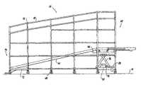
- FIG. 1is a side elevational view of the ramped passageway according to the present invention docked at one end to the terminal bus and at its other end to an aircraft;
- FIG. 2is a perspective view of the frame structure forming the passageway shown in FIG. 1 ;
- FIG. 3is a perspective view of an expanded frame section of the passageway according to the present invention.
- FIG. 4Ais a perspective view of the frame sections shown in FIG. 3 with the frame section collapsed;
- FIG. 4Bis a reverse perspective view of the frame section shown in FIG. 4A ;
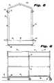
- FIG. 5is a front elevational view of the frame section shown in FIG. 3 ;
- FIG. 6is a side elevational view of the frame section shown in FIG. 3 ;
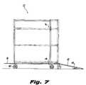
- FIG. 7is a side elevational view of the frame section shown in FIG. 4B ;
- FIG. 8is a top plan view of the walkway illustrating the articulated relationship between the sections.
- FIG. 9is a side elevational view of the gangway section showing the various inner elements of the gangway.
- the movable walkway of the present invention depicted by the numeral 10is generally illustrated in FIG. 1 . As illustrated the walkway is installed to permit passengers to walk from a bus 12 (or from a terminal exit) directly to an aircraft 14 waiting on the airport apron 16 .
- the construction of the walkway 10is illustrated in FIG. 2 , without any enclosure or covering.
- the walkway 10thus is formed of frame like skeleton structures divided into a plurality of sections each similar in construction to that shown in my earlier patent, namely a plurality of partially collapsible fixed height corridor sections 22 (only one shown) and an inclined gangway section 24 .
- the corridor sections 22are articulately connected to each other and to the inclined gangway 24 in sequence, in a manner to be described hereinafter, with respect to FIG. 8 .
- each corridor section 22comprises a plurality of U-shaped supports 26 .
- Each support 26is formed ( FIG. 5 ) of a pair of vertically disposed tubular legs 28 and a connecting roof arch beam 30 .
- the vertical legs 28each terminate at their upper ends in a clevis 32 into which the respective ends of the individual arched roof beam 30 seat.
- the cross-section of the vertical upright legs 28is somewhat larger than that of the arched roof beam 32 and suitable bolts or pins inserted therethrough hold the arched roof beam 32 fixedly to the upright legs 28 much in the manner shown in my earlier patent.
- the U-shaped supports 26are interconnected by a plurality of horizontal cross braces 34 .
- the cross braces 34will be fixed at each of their ends to the vertical legs 28 , by suitable bolts or weldments so as to rigidly maintain the vertical supports 26 aligned and parallel with one another.
- the length of each corridor 22is fixed.
- each corridor section 22alternate vertical supports 26 , (central support when only three supports are used) are provided with a cuff like guide 36 fixed in alignment with each of the braces 34 .
- a three support corridoris divided into two portions, denominated for conveyance as the anterior A and the posterior B portions.
- the set of the braces 34 , of the anterior portionare not attached to the center support but freely move through the corresponding guide 36 .
- the portions A & Bcan seemingly telescope with respect to each other as seen in the figures.
- a sub-flooring, generally depicted by the numeral 38is provided as seen in detail in FIG. 2 .
- the sub-flooring 38comprises an array of longitudinal braces 40 similar to the braces 34 and arranged similarly as described above so that one set of braces 40 slide freely through cuff-like guides 42 fixed to the corresponding support 26 , thus maintaining the collapsibility.
- Interconnecting the opposed floor brace 40is an array of longitudinal and transverse floor beams 44 .
- Each arrangement of braces 40 and floor beams 44are staggered at different levels to each other, to maintain collapsibility, by sliding one over the other as seen in FIGS. 4 a , 4 b & 6 .
- the sub-flooris arranged upward of the lower ends 46 of the vertical legs so as to be spaced from the ground.
- Each vertical leg 28is provided with a roller or caster 48 at its lower end. (for the sake of clarity not all the drawings show the rollers.)
- each sectionis completed by attaching a central deck plate 50 over each sub floor 38 .
- an inclined transitional ramp 52is attached at the free end of the deck plate 50 in the anterior portion A of each corridor.
- the transitional ramp 52is provided with a folded-in bottom 54 forming a lip resting stability on the ground.
- the free end of the deck plate 50 in the posterior portion Bextends as a short shelf like member 56 adapted to extend outwardly over the adjacent floor in the next sequential corridor or gangway section.
- the transitional ramp 52 and the extensions 56are provided with holes 57 which will register with each other on serially arranging the corridors so as to form pivot bearings allow the corridors 22 to articulate or swing relative to each other with a defined arc.
- the gangway 24is constructed having a plurality of vertically oriented U-shaped supports 58 and horizontal braces 60 , similar to those used in formation of the rigid fixed section 22 , except that they increase in height from the anterior end 62 where they are aligned and equal in height to those forming the corridor section 22 to a height at its posterior end 64 capable of fully enclosing the doorway opening of any commuter or small aircraft.
- a second distinction between the gangway 24 and the corridor 22lies in the fact that the frame structure is not collapsible and the braces 60 are fixedly on the vertical supports held at each end as well as between the ends to form a fixed length passageway.
- the gangway 24is provided with a raisable sub-floor, generally depicted by the numeral 66 formed of parallel side beams and a plurality of cross beams in the arrangement of a ladder.
- the sub-floor 66is pivotedly attached at its rear anterior end 68 to the lower beams of the gangway 24 so as to be raisable at its posterior end 64 , by means of a carriage assembly 70 slideably mounted in the lower most anterior brace 72 , which is formed in the shape of a c-channel. (see also FIG. 9 .)
- auxiliary deck plate 76extends forwardly to form a continuous extension ramp through the gangway 24 .
- a horizontal stable platform 78which is guided within a pair of horizontally opposed rails 80 , so as to be able to reciprocally slide between a first position cantilevered outward from the gangway passage 24 to a second storage position within the gangway 24 .
- the rails 80are themselves guided by vertical tracks 82 and are connected to the posterior end of the sub-flooring 66 , by a curved hinge 84 ( FIG. 9 ).
- the stable platform 78is raised and lowered selectively by a scissor type elevating mechanism 86 .
- the upper and lower ends of the scissor 86ride is horizontal rails 88 , fixed to the lower portion of the vertical support, while the upper ends of the scissors 86 , ride in the respective horizontal rails 80 .
- the scissor 86is actuated by a reversible electric motor 90 and screw transmission system 92 to elevate the platforms 78 and the forward end of the sub-floor 66 . Having the anterior end 68 of the sub-floor mounted in a slidable carriage 70 avoids binding or other problems, as the sub-floor 66 is raised at the posterior end.
- an inclined ramp 94is formed within the gangway 24 which can be elevated to the proper height of the aircraft door and whereby the stable platform 78 can be extended to abut the door sill providing a smooth walking transition for the passengers from ground level to aircraft level.
- FIG. 8also shows the pivot pin arranged between the aligned corridor section 22 .
- bracket 102fixed to the lower most portion of the posterior end of the gangway 24 .
- This bracket 102is employed to allow a motive drive device such as an electric cart to be hooked thereto enabling the operator of the cart to easily maneuver and move the walkway.
- the corridor and inclined gangway sections 22 and 24are covered in the manner described in my earlier patent with a fabric cover capable of maintaining suitable condition within the walkway no matter the anterior weather condition.
- the fabricmay be provided with windows, removable panels or screens.
- rigid plastic or metal wall panelscan be installed along the bottom of the corridor or inclined gangway sections 22 and 24 to insure the absence of rain or snow with the passageway.
Landscapes
- Engineering & Computer Science (AREA)
- Mechanical Engineering (AREA)
- Aviation & Aerospace Engineering (AREA)
- Architecture (AREA)
- Civil Engineering (AREA)
- Structural Engineering (AREA)
- Escalators And Moving Walkways (AREA)
- Bridges Or Land Bridges (AREA)
Abstract
Description
Claims (13)
Priority Applications (1)
| Application Number | Priority Date | Filing Date | Title |
|---|---|---|---|
| US09/854,082US7069611B2 (en) | 2000-05-12 | 2001-05-11 | Regional boarding ramp for commuter aircraft |
Applications Claiming Priority (2)
| Application Number | Priority Date | Filing Date | Title |
|---|---|---|---|
| US20372200P | 2000-05-12 | 2000-05-12 | |
| US09/854,082US7069611B2 (en) | 2000-05-12 | 2001-05-11 | Regional boarding ramp for commuter aircraft |
Publications (2)
| Publication Number | Publication Date |
|---|---|
| US20040211014A1 US20040211014A1 (en) | 2004-10-28 |
| US7069611B2true US7069611B2 (en) | 2006-07-04 |
Family
ID=22755049
Family Applications (1)
| Application Number | Title | Priority Date | Filing Date |
|---|---|---|---|
| US09/854,082Expired - Fee RelatedUS7069611B2 (en) | 2000-05-12 | 2001-05-11 | Regional boarding ramp for commuter aircraft |
Country Status (3)
| Country | Link |
|---|---|
| US (1) | US7069611B2 (en) |
| AU (1) | AU2001263076A1 (en) |
| WO (1) | WO2001088274A1 (en) |
Cited By (22)
| Publication number | Priority date | Publication date | Assignee | Title |
|---|---|---|---|---|
| US20060059636A1 (en)* | 2002-06-28 | 2006-03-23 | Suggate Trevor R | Modular platform, walkway or ramp |
| US20070107147A1 (en)* | 2005-08-20 | 2007-05-17 | Hubner Gmbh | Seal for aircraft boarding stairs or boarding bridge |
| US20070235591A1 (en)* | 2004-03-23 | 2007-10-11 | Fmt International Trade Ab | Device for Passenger Bridges for Aircraft |
| US20070289074A1 (en)* | 2006-06-14 | 2007-12-20 | Hubner Gmbh | Aircraft boarding bridge or aircraft boarding stairs |
| US20080028973A1 (en)* | 2004-08-26 | 2008-02-07 | Nobuhiro Hayashi | Conveyance Apparatus with Lifting/Lowering Load Carrying Platform |
| US20090307853A1 (en)* | 2008-06-16 | 2009-12-17 | Setzer Jr Mitchell Olin | Protable docking station |
| US7653957B1 (en)* | 2008-05-07 | 2010-02-02 | Mark Edward Curtiss | Collapseable utility ramp |
| US20110078864A1 (en)* | 2009-10-06 | 2011-04-07 | Bennett Ronald W | Extended safety cage for retractable gangway |
| US20110232010A1 (en)* | 2010-03-24 | 2011-09-29 | Peterson Robert L | Microbridges for regional aircraft and methods of using same |
| US20110243693A1 (en)* | 2010-03-31 | 2011-10-06 | Andrew Brooks | Downwardly insertable vehicle restraints |
| DE202012008839U1 (en) | 2012-09-14 | 2012-10-31 | Hübner GmbH | Access tunnel to an airplane |
| US8806690B1 (en) | 2013-12-23 | 2014-08-19 | Keith Consolidated Industries, Inc. | Dual bridge aircraft passenger boarding ramp assembly and method |
| US8869334B1 (en)* | 2013-05-28 | 2014-10-28 | Grant Leum | Mobile loading dock with load-bearing frame |
| US20140352085A1 (en)* | 2013-06-03 | 2014-12-04 | East Island Aviation Services, Inc. | Apparatus to interface a boarding bridge and a low doorsill airplane |
| US20160193093A1 (en)* | 2013-07-03 | 2016-07-07 | Korea Airports Corporation | Automatic Slope Adjusting Device |
| US9434482B2 (en)* | 2012-09-17 | 2016-09-06 | Shenzhen Cimc-Tianda Airport Support Ltd | Cab of passenger boarding bridge and passenger boarding bridge having the same and docking method thereof |
| US20160376030A1 (en)* | 2015-06-24 | 2016-12-29 | HÜBNER GmbH & Co. KG | Access tunnel to an aircraft |
| US9637876B2 (en)* | 2013-06-25 | 2017-05-02 | Fmt International Trade Ab | Device for slanting floors in passenger bridges |
| US9688493B2 (en) | 2015-11-09 | 2017-06-27 | Grant Leum | Mobile loading dock with side extensions |
| US20170225803A1 (en)* | 2016-02-04 | 2017-08-10 | HÜBNER GmbH & Co. KG | Access device to an airplane |
| US10365016B1 (en)* | 2018-05-11 | 2019-07-30 | Grant Leum | Solar-powered mobile loading dock |
| US11028541B2 (en)* | 2018-12-22 | 2021-06-08 | Richard Carl Till | Modular bridge system |
Families Citing this family (10)
| Publication number | Priority date | Publication date | Assignee | Title |
|---|---|---|---|---|
| US6994505B2 (en)* | 2004-01-09 | 2006-02-07 | Frank's International | Pick-up and lay-down system and method |
| CN2717815Y (en)* | 2004-06-08 | 2005-08-17 | 中国国际海运集装箱(集团)股份有限公司 | Passenger bridge passageway cab apron apparatus and sprine lamination used for cab apron apparatus |
| FR2886624B1 (en)* | 2005-06-02 | 2007-09-28 | Air France Sa Soc | SAFETY EQUIPMENT FOR PASSENGER TRANSFER TUNNEL AND TUNNEL HAVING SUCH EQUIPMENT |
| CN103640449A (en)* | 2013-12-24 | 2014-03-19 | 威海广泰空港设备股份有限公司 | Automatic leveling device and method for landing stair platform |
| WO2016076696A1 (en)* | 2014-11-12 | 2016-05-19 | Maquinaria Jersa, Sa. De C.V. | Connecting cabin for aircraft transfer |
| FR3036100A1 (en)* | 2015-05-13 | 2016-11-18 | Acet-Cod | EQUIPMENT FOR THE COMFORT AND SAFETY OF PASSENGERS AND FOR AIRPORT SAFETY DURING LANDING AND LANDING OPERATIONS IN A RESERVED AREA. |
| CN107367391B (en)* | 2015-10-27 | 2019-05-31 | 浙江联宜电机有限公司 | Scooter climbing testboard |
| US9746846B1 (en) | 2016-09-09 | 2017-08-29 | Accenture Global Solutions Limited | Automated loading bridge positioning using encoded decals |
| US10908580B2 (en)* | 2016-09-09 | 2021-02-02 | Accenture Global Solutions Limited | Devices, systems, and methods for automated loading bridge positioning using shapes associated with a vehicle |
| CN114151712B (en)* | 2021-11-29 | 2023-08-18 | 中冶华天南京工程技术有限公司 | Accessible leveling support |
Citations (26)
| Publication number | Priority date | Publication date | Assignee | Title |
|---|---|---|---|---|
| US2362170A (en)* | 1942-08-10 | 1944-11-07 | Pacific Engineering Corp | Portable folding scaffold |
| US2470337A (en)* | 1947-01-20 | 1949-05-17 | Richard L Campbell | Extensible canopy |
| US2828757A (en)* | 1956-07-17 | 1958-04-01 | Tepee Trail Inc | Collapsible passageway |
| US3131705A (en)* | 1962-02-12 | 1964-05-05 | Marino Inc L | Stabilized portable canopy |
| US3599262A (en)* | 1970-04-21 | 1971-08-17 | Cochran Western Corp | Attitude sensing system for use during loading and unloading of vehicles |
| US3683440A (en)* | 1970-10-13 | 1972-08-15 | Sperry Rand Corp | Automatic terminal bridge control system |
| US3687321A (en)* | 1970-03-24 | 1972-08-29 | Stanray Corp | Load carrying vehicle |
| US3845591A (en)* | 1973-06-11 | 1974-11-05 | J Stine | Expandable cover system |
| US3944096A (en)* | 1974-04-01 | 1976-03-16 | Cochran-Boothe Airport Systems | Freight transporter and loader for aircraft |
| US3964118A (en)* | 1975-04-28 | 1976-06-22 | Marriott Corporation | Cargo transfer vehicle with double angle catwalk adjustment |
| US4084713A (en)* | 1976-05-03 | 1978-04-18 | Collins Industries, Inc. | Vehicle wheelchair ramp |
| US4161049A (en)* | 1977-11-01 | 1979-07-17 | Abex Corporation | Passenger loading bridge |
| US4319376A (en)* | 1978-06-05 | 1982-03-16 | Abex Corporation | Passenger loading bridge |
| US4344200A (en)* | 1980-09-25 | 1982-08-17 | Abex Corporation | Bridge brake system |
| US4488326A (en)* | 1982-09-30 | 1984-12-18 | Autoquip Corporation | Pallet dock lift |
| US4517698A (en)* | 1983-01-05 | 1985-05-21 | Lamp L Thomas A | Cargo handling ramp |
| US4553720A (en)* | 1983-03-31 | 1985-11-19 | Thyssen Industrie Aktiengesellschaft | Connecting mechanism for an airplane passenger bridge |
| US4768617A (en)* | 1987-07-16 | 1988-09-06 | Wenger Corporation | Adjustable stairway having retractable wheel carriage |
| US4886413A (en)* | 1988-04-29 | 1989-12-12 | Fmc Corporation | Loader platform interface control and stop means |
| US5105915A (en)* | 1990-12-24 | 1992-04-21 | Gary Jerry M | Wheelchair lifting device |
| US5137114A (en)* | 1991-10-28 | 1992-08-11 | The Moving Company | Stair track device |
| US5226204A (en)* | 1991-02-12 | 1993-07-13 | Subtechnique, Inc. | Tele-robotic passenger loading bridge control system |
| US5603343A (en)* | 1995-02-03 | 1997-02-18 | James Larson | Passageway for loading and unloading aircraft |
| US6055692A (en)* | 1997-02-24 | 2000-05-02 | Accessair Systems, Inc. | Boarding bridge for commuter type aircraft or the like |
| US6330726B1 (en)* | 2000-02-18 | 2001-12-18 | Fmc Corporation | Gangway system |
| US6481039B1 (en)* | 2001-05-23 | 2002-11-19 | Dew Engineering And Development Limited | Passenger loading bridge extending from a terminal at ground level and for servicing aircraft of various sizes |
Family Cites Families (5)
| Publication number | Priority date | Publication date | Assignee | Title |
|---|---|---|---|---|
| US3046850A (en)* | 1958-03-10 | 1962-07-31 | Clair W Tellefson | Foldable walkway and storage apparatus therefor |
| US3422477A (en)* | 1966-07-14 | 1969-01-21 | Wollard Aircraft Equipment Inc | Telescoping conveyance loader |
| US3538528A (en)* | 1968-08-01 | 1970-11-10 | Gorden Jacobson | Access ramp |
| US3779596A (en)* | 1972-07-28 | 1973-12-18 | Avco Corp | Mobile passenger loading lounge for aircraft |
| US5704086A (en)* | 1996-01-02 | 1998-01-06 | Fmc Corporation | Passenger boarding bridge |
- 2001
- 2001-05-11USUS09/854,082patent/US7069611B2/ennot_activeExpired - Fee Related
- 2001-05-14AUAU2001263076Apatent/AU2001263076A1/ennot_activeAbandoned
- 2001-05-14WOPCT/US2001/015345patent/WO2001088274A1/enactiveApplication Filing
Patent Citations (26)
| Publication number | Priority date | Publication date | Assignee | Title |
|---|---|---|---|---|
| US2362170A (en)* | 1942-08-10 | 1944-11-07 | Pacific Engineering Corp | Portable folding scaffold |
| US2470337A (en)* | 1947-01-20 | 1949-05-17 | Richard L Campbell | Extensible canopy |
| US2828757A (en)* | 1956-07-17 | 1958-04-01 | Tepee Trail Inc | Collapsible passageway |
| US3131705A (en)* | 1962-02-12 | 1964-05-05 | Marino Inc L | Stabilized portable canopy |
| US3687321A (en)* | 1970-03-24 | 1972-08-29 | Stanray Corp | Load carrying vehicle |
| US3599262A (en)* | 1970-04-21 | 1971-08-17 | Cochran Western Corp | Attitude sensing system for use during loading and unloading of vehicles |
| US3683440A (en)* | 1970-10-13 | 1972-08-15 | Sperry Rand Corp | Automatic terminal bridge control system |
| US3845591A (en)* | 1973-06-11 | 1974-11-05 | J Stine | Expandable cover system |
| US3944096A (en)* | 1974-04-01 | 1976-03-16 | Cochran-Boothe Airport Systems | Freight transporter and loader for aircraft |
| US3964118A (en)* | 1975-04-28 | 1976-06-22 | Marriott Corporation | Cargo transfer vehicle with double angle catwalk adjustment |
| US4084713A (en)* | 1976-05-03 | 1978-04-18 | Collins Industries, Inc. | Vehicle wheelchair ramp |
| US4161049A (en)* | 1977-11-01 | 1979-07-17 | Abex Corporation | Passenger loading bridge |
| US4319376A (en)* | 1978-06-05 | 1982-03-16 | Abex Corporation | Passenger loading bridge |
| US4344200A (en)* | 1980-09-25 | 1982-08-17 | Abex Corporation | Bridge brake system |
| US4488326A (en)* | 1982-09-30 | 1984-12-18 | Autoquip Corporation | Pallet dock lift |
| US4517698A (en)* | 1983-01-05 | 1985-05-21 | Lamp L Thomas A | Cargo handling ramp |
| US4553720A (en)* | 1983-03-31 | 1985-11-19 | Thyssen Industrie Aktiengesellschaft | Connecting mechanism for an airplane passenger bridge |
| US4768617A (en)* | 1987-07-16 | 1988-09-06 | Wenger Corporation | Adjustable stairway having retractable wheel carriage |
| US4886413A (en)* | 1988-04-29 | 1989-12-12 | Fmc Corporation | Loader platform interface control and stop means |
| US5105915A (en)* | 1990-12-24 | 1992-04-21 | Gary Jerry M | Wheelchair lifting device |
| US5226204A (en)* | 1991-02-12 | 1993-07-13 | Subtechnique, Inc. | Tele-robotic passenger loading bridge control system |
| US5137114A (en)* | 1991-10-28 | 1992-08-11 | The Moving Company | Stair track device |
| US5603343A (en)* | 1995-02-03 | 1997-02-18 | James Larson | Passageway for loading and unloading aircraft |
| US6055692A (en)* | 1997-02-24 | 2000-05-02 | Accessair Systems, Inc. | Boarding bridge for commuter type aircraft or the like |
| US6330726B1 (en)* | 2000-02-18 | 2001-12-18 | Fmc Corporation | Gangway system |
| US6481039B1 (en)* | 2001-05-23 | 2002-11-19 | Dew Engineering And Development Limited | Passenger loading bridge extending from a terminal at ground level and for servicing aircraft of various sizes |
Cited By (43)
| Publication number | Priority date | Publication date | Assignee | Title |
|---|---|---|---|---|
| US20060059636A1 (en)* | 2002-06-28 | 2006-03-23 | Suggate Trevor R | Modular platform, walkway or ramp |
| US7596826B2 (en)* | 2004-03-23 | 2009-10-06 | Fmt International Trade Ab | Device for passenger bridges for aircraft |
| US20070235591A1 (en)* | 2004-03-23 | 2007-10-11 | Fmt International Trade Ab | Device for Passenger Bridges for Aircraft |
| US20080028973A1 (en)* | 2004-08-26 | 2008-02-07 | Nobuhiro Hayashi | Conveyance Apparatus with Lifting/Lowering Load Carrying Platform |
| US7552683B2 (en)* | 2004-08-26 | 2009-06-30 | Daifuku Co., Ltd. | Conveying apparatus with lifting/lowering platform |
| US20070107147A1 (en)* | 2005-08-20 | 2007-05-17 | Hubner Gmbh | Seal for aircraft boarding stairs or boarding bridge |
| US7360268B2 (en)* | 2005-08-20 | 2008-04-22 | Hubner Gmbh | Seal for aircraft boarding stairs or boarding bridge |
| US20070289074A1 (en)* | 2006-06-14 | 2007-12-20 | Hubner Gmbh | Aircraft boarding bridge or aircraft boarding stairs |
| US7690065B2 (en)* | 2006-06-14 | 2010-04-06 | Hübner GmbH | Aircraft boarding bridge or aircraft boarding stairs |
| US7653957B1 (en)* | 2008-05-07 | 2010-02-02 | Mark Edward Curtiss | Collapseable utility ramp |
| US20090307853A1 (en)* | 2008-06-16 | 2009-12-17 | Setzer Jr Mitchell Olin | Protable docking station |
| US7870629B2 (en)* | 2008-06-16 | 2011-01-18 | Setzer Jr Mitchell Olin | Portable docking station |
| US20110078864A1 (en)* | 2009-10-06 | 2011-04-07 | Bennett Ronald W | Extended safety cage for retractable gangway |
| US8015647B2 (en)* | 2009-10-06 | 2011-09-13 | Aluminum Ladder Company | Extended safety cage for retractable gangway |
| US8266750B2 (en)* | 2010-03-24 | 2012-09-18 | Gatelink Aircraft Boarding Systems, Inc. | Microbridges for regional aircraft and methods of using same |
| US20160009414A1 (en)* | 2010-03-24 | 2016-01-14 | Robert L. Peterson | Microbridges for regional aircraft and methods of using same |
| US9815572B2 (en) | 2010-03-24 | 2017-11-14 | Gatelink Aircraft Boarding Systems, Inc. | Microbridges for regional aircraft and methods of using same |
| US11021268B2 (en) | 2010-03-24 | 2021-06-01 | Gatelink Aircraft Boarding Systems, Inc. | Microbridges for regional aircraft and methods of using same |
| US8677540B2 (en) | 2010-03-24 | 2014-03-25 | Gatelink Aircraft Boarding Systems, Inc. | Microbridges for regional aircraft and methods of using the same |
| US20230348102A1 (en)* | 2010-03-24 | 2023-11-02 | Gatelink Aircraft Boarding Systems, Inc. | Microbridges for regional aircraft and methods of using same |
| US20110232010A1 (en)* | 2010-03-24 | 2011-09-29 | Peterson Robert L | Microbridges for regional aircraft and methods of using same |
| US9487307B2 (en)* | 2010-03-24 | 2016-11-08 | Gatelink Aircraft Boarding Systems, Inc. | Microbridges for regional aircraft and methods of using same |
| US9096397B2 (en)* | 2010-03-31 | 2015-08-04 | Rite-Hite Holding Corporation | Downwardly insertable vehicle restraints |
| US20110243693A1 (en)* | 2010-03-31 | 2011-10-06 | Andrew Brooks | Downwardly insertable vehicle restraints |
| DE202012008839U1 (en) | 2012-09-14 | 2012-10-31 | Hübner GmbH | Access tunnel to an airplane |
| US9434482B2 (en)* | 2012-09-17 | 2016-09-06 | Shenzhen Cimc-Tianda Airport Support Ltd | Cab of passenger boarding bridge and passenger boarding bridge having the same and docking method thereof |
| US8869334B1 (en)* | 2013-05-28 | 2014-10-28 | Grant Leum | Mobile loading dock with load-bearing frame |
| US20140352085A1 (en)* | 2013-06-03 | 2014-12-04 | East Island Aviation Services, Inc. | Apparatus to interface a boarding bridge and a low doorsill airplane |
| US9284066B2 (en)* | 2013-06-03 | 2016-03-15 | East Island Aviation Services, Inc. | Apparatus to interface a boarding bridge and a low doorsill airplane |
| US9409657B2 (en) | 2013-06-03 | 2016-08-09 | East Island Aviation Services, Inc. | Apparatus to interface a boarding bridge and a low doorsill airplane |
| US9637876B2 (en)* | 2013-06-25 | 2017-05-02 | Fmt International Trade Ab | Device for slanting floors in passenger bridges |
| US20160193093A1 (en)* | 2013-07-03 | 2016-07-07 | Korea Airports Corporation | Automatic Slope Adjusting Device |
| US9839564B2 (en)* | 2013-07-03 | 2017-12-12 | Korea Airports Corporation | Automatic slope adjusting device |
| US8863341B1 (en) | 2013-12-23 | 2014-10-21 | William Floyd Keith | Dual bridge aircraft passenger boarding ramp assembly and method |
| US8806690B1 (en) | 2013-12-23 | 2014-08-19 | Keith Consolidated Industries, Inc. | Dual bridge aircraft passenger boarding ramp assembly and method |
| US9745080B2 (en)* | 2015-06-24 | 2017-08-29 | HÜBNER GmbH & Co. KG | Access tunnel to an aircraft |
| US20160376030A1 (en)* | 2015-06-24 | 2016-12-29 | HÜBNER GmbH & Co. KG | Access tunnel to an aircraft |
| US9688493B2 (en) | 2015-11-09 | 2017-06-27 | Grant Leum | Mobile loading dock with side extensions |
| CN107031862A (en)* | 2016-02-04 | 2017-08-11 | 许布奈有限两合公司 | Into the entrance equipment of aircraft |
| US20170225803A1 (en)* | 2016-02-04 | 2017-08-10 | HÜBNER GmbH & Co. KG | Access device to an airplane |
| US9969506B2 (en)* | 2016-02-04 | 2018-05-15 | HÜBNER GmbH & Co. KG | Access device to an airplane |
| US10365016B1 (en)* | 2018-05-11 | 2019-07-30 | Grant Leum | Solar-powered mobile loading dock |
| US11028541B2 (en)* | 2018-12-22 | 2021-06-08 | Richard Carl Till | Modular bridge system |
Also Published As
| Publication number | Publication date |
|---|---|
| AU2001263076A1 (en) | 2001-11-26 |
| WO2001088274A1 (en) | 2001-11-22 |
| US20040211014A1 (en) | 2004-10-28 |
Similar Documents
| Publication | Publication Date | Title |
|---|---|---|
| US7069611B2 (en) | Regional boarding ramp for commuter aircraft | |
| US3664456A (en) | Conveyance servicing structure | |
| AU609175B2 (en) | Airbridge | |
| US5603343A (en) | Passageway for loading and unloading aircraft | |
| CA2138779C (en) | A combined stairs and person hoist | |
| US6055692A (en) | Boarding bridge for commuter type aircraft or the like | |
| US6212724B1 (en) | Passenger boarding bridge for narrow body aircraft | |
| KR101886436B1 (en) | Transport installation with an aerial cable provided with a maintenance vehicle | |
| US20220041300A1 (en) | Microbridges for regional aircraft and methods of using same | |
| US8251177B2 (en) | Collapsible access tower | |
| CN107013045B (en) | Loading platform | |
| CA1095465A (en) | Wheelchair lift device | |
| US7422096B2 (en) | Extension for conveyor | |
| US10232956B2 (en) | Aerobridge providing multiple access points to aircraft vehicle | |
| US4319376A (en) | Passenger loading bridge | |
| US3391416A (en) | Conveyance loader system | |
| RU2540724C2 (en) | Ramp (versions) | |
| CN107031862A (en) | Into the entrance equipment of aircraft | |
| RU42421U1 (en) | PANDUS (OPTIONS) | |
| US3047891A (en) | Embarkation gangway | |
| US2778694A (en) | Mobile swinging lift platform equipment | |
| AU2006100845A4 (en) | Emergency evacuation system for track vehicle | |
| GB2140749A (en) | Wheelchair elevator for passenger vehicles | |
| CA2601829C (en) | Boarding bridge for commuter type aircraft or the like | |
| USRE26859E (en) | Conveyance loader system |
Legal Events
| Date | Code | Title | Description |
|---|---|---|---|
| AS | Assignment | Owner name:INFRA-STRUCTURES, INC., NEW YORK Free format text:ASSIGNMENT OF ASSIGNORS INTEREST;ASSIGNOR:LARSON, MR. JAMES;REEL/FRAME:016635/0523 Effective date:20050810 | |
| AS | Assignment | Owner name:FIFTH THIRD BANK (CHICAGO), ILLINOIS Free format text:SECURITY AGREEMENT;ASSIGNOR:INFRA-STRUCTURES, INC.;REEL/FRAME:016418/0116 Effective date:20050815 | |
| FEPP | Fee payment procedure | Free format text:PAYOR NUMBER ASSIGNED (ORIGINAL EVENT CODE: ASPN); ENTITY STATUS OF PATENT OWNER: SMALL ENTITY Free format text:PAYER NUMBER DE-ASSIGNED (ORIGINAL EVENT CODE: RMPN); ENTITY STATUS OF PATENT OWNER: SMALL ENTITY | |
| FEPP | Fee payment procedure | Free format text:PAYER NUMBER DE-ASSIGNED (ORIGINAL EVENT CODE: RMPN); ENTITY STATUS OF PATENT OWNER: SMALL ENTITY Free format text:PAYOR NUMBER ASSIGNED (ORIGINAL EVENT CODE: ASPN); ENTITY STATUS OF PATENT OWNER: SMALL ENTITY | |
| AS | Assignment | Owner name:AFC TRADING, INC., NEW YORK Free format text:ASSIGNMENT OF ASSIGNORS INTEREST;ASSIGNOR:FIFTH THIRD BANK (CHICAGO);REEL/FRAME:023456/0841 Effective date:20090227 | |
| FPAY | Fee payment | Year of fee payment:4 | |
| REMI | Maintenance fee reminder mailed | ||
| FPAY | Fee payment | Year of fee payment:8 | |
| SULP | Surcharge for late payment | Year of fee payment:7 | |
| FEPP | Fee payment procedure | Free format text:MAINTENANCE FEE REMINDER MAILED (ORIGINAL EVENT CODE: REM.) | |
| LAPS | Lapse for failure to pay maintenance fees | Free format text:PATENT EXPIRED FOR FAILURE TO PAY MAINTENANCE FEES (ORIGINAL EVENT CODE: EXP.) | |
| STCH | Information on status: patent discontinuation | Free format text:PATENT EXPIRED DUE TO NONPAYMENT OF MAINTENANCE FEES UNDER 37 CFR 1.362 |