US7068977B1 - Method and system for interference assessment and reduction in a wireless communication system - Google Patents
Method and system for interference assessment and reduction in a wireless communication systemDownload PDFInfo
- Publication number
- US7068977B1 US7068977B1US10/269,225US26922502AUS7068977B1US 7068977 B1US7068977 B1US 7068977B1US 26922502 AUS26922502 AUS 26922502AUS 7068977 B1US7068977 B1US 7068977B1
- Authority
- US
- United States
- Prior art keywords
- signal
- interference
- channel
- spatial signature
- channels
- Prior art date
- Legal status (The legal status is an assumption and is not a legal conclusion. Google has not performed a legal analysis and makes no representation as to the accuracy of the status listed.)
- Expired - Fee Related, expires
Links
- 238000004891communicationMethods0.000titleclaimsabstractdescription26
- 238000000034methodMethods0.000titleclaimsabstractdescription16
- 230000009467reductionEffects0.000titledescription9
- 239000013598vectorSubstances0.000claimsdescription24
- 239000011159matrix materialSubstances0.000claimsdescription11
- 238000012549trainingMethods0.000claimsdescription6
- 238000010586diagramMethods0.000description9
- 230000002452interceptive effectEffects0.000description7
- 230000005540biological transmissionEffects0.000description6
- 238000005516engineering processMethods0.000description6
- 238000012545processingMethods0.000description6
- 230000007246mechanismEffects0.000description4
- 238000007781pre-processingMethods0.000description4
- 230000003044adaptive effectEffects0.000description2
- 230000000875corresponding effectEffects0.000description2
- 238000001514detection methodMethods0.000description2
- 230000000694effectsEffects0.000description2
- 230000002708enhancing effectEffects0.000description2
- 230000008569processEffects0.000description2
- 238000005070samplingMethods0.000description2
- 230000001360synchronised effectEffects0.000description2
- 230000008901benefitEffects0.000description1
- 210000004027cellAnatomy0.000description1
- 210000003850cellular structureAnatomy0.000description1
- 230000001143conditioned effectEffects0.000description1
- 230000002596correlated effectEffects0.000description1
- 238000009795derivationMethods0.000description1
- 238000013461designMethods0.000description1
- 230000008030eliminationEffects0.000description1
- 238000003379elimination reactionMethods0.000description1
- 238000001914filtrationMethods0.000description1
- 230000002085persistent effectEffects0.000description1
- 230000035755proliferationEffects0.000description1
- 238000003908quality control methodMethods0.000description1
- 230000008054signal transmissionEffects0.000description1
- 238000001228spectrumMethods0.000description1
- 230000007480spreadingEffects0.000description1
Images


Classifications
- H—ELECTRICITY
- H04—ELECTRIC COMMUNICATION TECHNIQUE
- H04B—TRANSMISSION
- H04B17/00—Monitoring; Testing
- H—ELECTRICITY
- H04—ELECTRIC COMMUNICATION TECHNIQUE
- H04B—TRANSMISSION
- H04B17/00—Monitoring; Testing
- H04B17/0082—Monitoring; Testing using service channels; using auxiliary channels
- H04B17/0087—Monitoring; Testing using service channels; using auxiliary channels using auxiliary channels or channel simulators
- H—ELECTRICITY
- H04—ELECTRIC COMMUNICATION TECHNIQUE
- H04B—TRANSMISSION
- H04B17/00—Monitoring; Testing
- H04B17/30—Monitoring; Testing of propagation channels
- H04B17/309—Measuring or estimating channel quality parameters
- H04B17/345—Interference values
- H—ELECTRICITY
- H04—ELECTRIC COMMUNICATION TECHNIQUE
- H04B—TRANSMISSION
- H04B7/00—Radio transmission systems, i.e. using radiation field
- H04B7/02—Diversity systems; Multi-antenna system, i.e. transmission or reception using multiple antennas
- H04B7/04—Diversity systems; Multi-antenna system, i.e. transmission or reception using multiple antennas using two or more spaced independent antennas
- H04B7/08—Diversity systems; Multi-antenna system, i.e. transmission or reception using multiple antennas using two or more spaced independent antennas at the receiving station
- H04B7/0837—Diversity systems; Multi-antenna system, i.e. transmission or reception using multiple antennas using two or more spaced independent antennas at the receiving station using pre-detection combining
- H04B7/0842—Weighted combining
- H—ELECTRICITY
- H04—ELECTRIC COMMUNICATION TECHNIQUE
- H04W—WIRELESS COMMUNICATION NETWORKS
- H04W24/00—Supervisory, monitoring or testing arrangements
Definitions
- the present inventionrelates to wireless communication system in general, and more particularly, to a method and system for noise and interference reduction in a wireless communication system.
- a wireless communication systeminvolves a cellular structure where a call control and management device such as a base station communicates with a number of mobile terminals using a predetermined frequency band. For every terminal, signals other than those that are destined for it are considered to be noises or interferences fro other sources.
- the sources for the interferencescan vary in a great deal. For example, each terminal may represent a potential source of interference for other mobile terminal in the same coverage area. Given the market acceptance of wireless communication devices, the number of wireless communications devices will probably only increase over the next several years. As such, the interference is likely to increase over time.
- an adaptive antenna arrayalso referred to as a smart antenna, having interference reduction or nulling capabilities may be used.
- the antenna arraytypically contains one or more antenna elements.
- the receivers of base stations or terminalsreceive the combination of the signals of interest and interfering communication signals transmitted from other sources including persistent noises such as the thermal noise.
- preprocessingsuch as channelization and CDMA despreading, it may be possible to enhance the signal of interest and suppress any interference and noise components.
- the power levels of interference componentsare significantly higher than those of the signals of interest, a sufficiently high signal to interference and noise ratio is hard to obtain to assure a correct detection of the signals of interest or the underlying digital symbols.
- a method and system for interference assessment and reductionis disclosed.
- the present disclosuredescribes a method and system for accurately detecting the characteristics of the interfering signals from relevant sources utilizing an antenna array.
- the antenna arrayuses one or more signal channels for communicating with one or more mobile terminals.
- at least one channelis assigned as an empty channel in which no desired signal is carried so as to provide a representation of all relevant interference. Since the spatial characteristics of the interference on the empty channel and the regular signal channels should be very similar, the spatial signature of the signal channels is analyzed based on the interference received on the empty channel and the desired signals received on at least one signal channel. The analyzed spatial signature is then used for reducing the interference on all signal channels.
- a base stationdesignates a code channel in which the expected communications between the base station and a particular terminal is withheld while every other communication code channels are still used as normal.
- the interfering signalscan be well exposed and the characteristics can be accurately detected in the designated code channel.
- the base stationcan specifically design beamforming mechanism or other means to cancel or minimize the impact of such interference during regular uses of all code channels.
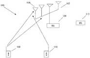
- FIG. 1illustrates wireless communication system utilizing an antenna array.
- FIGS. 2–5illustrate four flow diagrams for estimating and reducing the interference according to different embodiments of the present disclosure.
- the present disclosureintroduces a unique inactive code channel for each antenna array such that only the interferences generated from relevant sources will be better estimated due to the lack of regular data signals. The characteristics of all interfering signals are thus captured and used for canceling such signals in other communications using other code channels.
- FIG. 1shows a wireless communication system 100 having an adaptive array antenna 102 for receiving, transmitting, and processing a wireless transmission signal.
- the array 102includes m antenna elements 104 , each of which may be coupled to a separate train of signal processing equipment with a base site such as a base station (BS) 106 .
- Each train of signal processing equipmentincludes components such as a radio frequency receiver and analog-to-digital converter, subchannel demodulator, or symbol synchronizer.
- the symbol synchronizercontrols a plurality of sampling devices to sample the signal at a rate that is determined according to a conventional symbol rate sampling algorithm.
- each of the signals received by the array elements 104constitutes a distinct and different superposition or summation of different reflections of an original signal transmitted by, for example, one of the mobile terminals 108 .
- the received signalmay contain a direct “line of sight” component that is not reflected off of any surfaces so that the received signal at each array element 104 may include an original signal.
- the received signaltypically is a summation of a plurality of reflections of the original signal, or a summation of the original signal and the plurality of reflections of the original signal.
- the signal received by each antenna element 104also contains interferences from other mobile terminals such as terminal 110 , or base sites 112 as well as random noises.
- the signal from the mobile terminal 108 that the antenna array 102 is attempting to receivewill be referred to as a “desired signal” and the signals from other mobile terminals and base sites will be referred to as “interference signals”.
- the signalsare then processed by the train of signal processing equipment associated with each element. In one example, certain weight calculator determines weights to be supplied to limit the effects of interference and noise.
- the received signals at different antenna elements 104 of that antenna array 102can be mathematically modeled as a vector multiplied by the initially sent signal. That vector is usually determined by various factors including the location of the mobile terminal, the propagation environment, the configuration of the antenna array elements, carrier frequency, etc. These factors are collectively referred to as the spatial signature of the mobile terminal. Similarly, the concept of spatial signature can apply to any transmission device. In the following discussion, although a mobile terminal may be used as one example of the transmission device, it is not limited to a mobile terminal such as terminal 108 or 110 of FIG. 1 , and can be any signal transmission source. Moreover, in one example of the present disclosure, a synchronous CDMA communication system will be used to illustrate the invention, but the principles thereof can be applied to TDMA, OFDM, FDMA, or any similar systems.
- mobile terminalsare assigned with orthogonal spreading codes known as code channels, which separates the signals in the code domain.
- code channelsorthogonal spreading codes
- the transmission time for signals in these code channelsis adjusted so the signals sent from a mobile terminal (e.g., terminal 108 ) may arrive at the antenna array 104 at almost the same time. It is understood that if the timing accuracy is not maintained, then signals transmitted from other terminals will pose interference. As mentioned earlier, transmissions from other cells and other systems also lead to interference with the desired terminal's signal at the antenna.
- the antenna array 102 along with the base station 106is expected to provide solutions to suppress interferences. From the perspective of the antenna array, since each mobile terminal has its own unique spatial signature, transmission devices at different locations will have different spatial signatures.
- CDMA technologydivides a radio spectrum into wideband digital radio signals with each signal waveform carrying several different coded channels, while each coded channel is identified by a unique channel code.
- the processing mechanismseparates the channels by correlating or matching signals with the proper channel code sequence and enhancing the correlated one without enhancing others.
- the majority of code channelsare used for voice or data communications, but a small number of code channels are used for control purposes such as the pilot, synchronization, paging, and access channels.
- FIG. 2is a flow diagram 200 illustrating one example of the present disclosure for interference assessment and reduction.
- one or more code channelsare preserved for signal quality control purposes only (referred to as “empty channels”). Unlike the other code channels, these empty channels will not carry any desired signal at all so that the information represented thereon is merely unneeded interference including noises.
- the characteristics of the exposed interferencecan then be detected and used for the elimination or reduction thereof on other code channels. For example, using the empty channel, the base station and a particular terminal do not transmit signals at all or transmit signals at power levels that are detectably lower than normal to facilitate the assessment of the interference so that it can be dealt with more efficiently.
- preprocessingsuch as the despreading process is done to extract each code channel symbols from a wideband signal.
- multiple access schemeis using the Orthogonal Frequency Division Multiple Access (OFDM) technology
- FFTfast Fourier transform
- FDMAFrequency Division Multiple Access
- filtering mechanismare used to decompose a wideband signal into multiple narrow-band signals.
- TDMATime Division Multiple Access
- preprocessingsimply means to separate the signal into different groups based on the time slots they occupy.
- the covariance matrix R in of the empty channelis estimated.
- the signal spatial signatureis estimated based on R x and R in .
- an estimation of a receive/uplink beam forming vector w nullis done based on a in step 210 .
- the communication signals receivedare then appropriately demodulated based on y(n).
- a transmit/downlink beam forming vectorcan be estimated based on a receive beam forming vector and calibration vectors.
- FIG. 3is a flow diagram 300 illustrating another embodiment for estimating and reducing the interferences.
- the flow diagram 300is similar to the flow diagram 200 of FIG. 2 except that steps 206 and 208 are now replaced by step 306 in which the spatial signature is estimated with the assistance of a training sequence s(n) in the code channel.
- Steps 302 , 304 , 308 and 310matches the steps 202 , 204 , 210 , and 212 of FIG. 2 . Since the wireless communication system is full aware of what's in the training sequence, it would be easier to detect the spatial signature and assess other interference.
- FIG. 4is a flow diagram 400 illustrating another embodiment of the present disclosure. Steps 402 – 412 are the same as steps 202 – 212 respectively, and then in step 414 , the signal s(n) of the code channel is derived from y(n). Once the s(n) is derived, in step 416 , it is plugged back into formula
- FIG. 5is another flow diagram 500 illustrating one other embodiment of the present disclosure.
- the diagram 500is similar to the diagram 300 except that after y(n) is obtained, the signal s(n) of the signal channel is derived from y(n) in step 512 . The s(n) is then fed back to step 506 where the spatial signature a is better estimated using the training sequence.
- the s(n)can be cached temporarily after step 512 so that when in a next round of derivation, a new s(n) can be compared with the stored s(n). A tolerance between these two s(n) values can be set up to decide whether the new s(n) needs to be fed back to step 506 . Therefore, the convergence of the values of s(n) in different rounds of estimation helps to obtain the best spatial signature for interference reduction. It is also possible that the repetition through the feedback loop formed by steps 506 – 512 can be set at a predetermined number by the operator.
- the spatial signature of the current frameis compared with ones obtained in the previous frames according to some predetermined criteria to keep it updated and accurate in an interference environment.
- the interference reduction taking advantage of the empty channelscan be implemented through both the base station and the terminals. These two ends of the communications can cooperate to make channel assignment and interference reduction more efficient. Since conventionally, the base station has more processing capacity than the terminal, estimation of the profile of the interference can be done there. However, as the terminal gets more intelligent, a lot of the analysis can also be done on the terminal. The improved beam forming mechanism can then be also implemented on the terminal side.
- the empty channelis a predetermined code channel. If the wireless communication system is using Time Division Multiple Access technology, the empty channel can be a time slot. Similarly, the empty channel can be frequency bins for OFDM technology based systems and subcarriers in FDMA technology based systems.
Landscapes
- Engineering & Computer Science (AREA)
- Computer Networks & Wireless Communication (AREA)
- Signal Processing (AREA)
- Physics & Mathematics (AREA)
- Electromagnetism (AREA)
- Quality & Reliability (AREA)
- Mobile Radio Communication Systems (AREA)
- Noise Elimination (AREA)
Abstract
Description
to get a better spatial signature to be used for other channels.
Claims (10)
Priority Applications (7)
| Application Number | Priority Date | Filing Date | Title |
|---|---|---|---|
| US10/269,225US7068977B1 (en) | 2002-10-11 | 2002-10-11 | Method and system for interference assessment and reduction in a wireless communication system |
| PCT/US2003/027072WO2004034615A1 (en) | 2002-10-11 | 2003-08-29 | Method and system for interference assessment and reduction in a wireless communication system |
| AT03749206TATE554543T1 (en) | 2002-10-11 | 2003-08-29 | METHOD AND SYSTEM FOR FAULT ASSESSMENT AND REDUCTION IN A WIRELESS COMMUNICATION SYSTEM |
| EP03749206AEP1550250B1 (en) | 2002-10-11 | 2003-08-29 | Method and system for interference assessment and reduction in a wireless communication system |
| AU2003268253AAU2003268253A1 (en) | 2002-10-11 | 2003-08-29 | Method and system for interference assessment and reduction in a wireless communication system |
| CN038240556ACN1703854B (en) | 2002-10-11 | 2003-08-29 | Method and system for interference assessment and reduction in wireless communication systems |
| KR1020057006254AKR101004661B1 (en) | 2002-10-11 | 2003-08-29 | Method and system for interference evaluation and reduction in wireless communication system |
Applications Claiming Priority (1)
| Application Number | Priority Date | Filing Date | Title |
|---|---|---|---|
| US10/269,225US7068977B1 (en) | 2002-10-11 | 2002-10-11 | Method and system for interference assessment and reduction in a wireless communication system |
Publications (1)
| Publication Number | Publication Date |
|---|---|
| US7068977B1true US7068977B1 (en) | 2006-06-27 |
Family
ID=32092420
Family Applications (1)
| Application Number | Title | Priority Date | Filing Date |
|---|---|---|---|
| US10/269,225Expired - Fee RelatedUS7068977B1 (en) | 2002-10-11 | 2002-10-11 | Method and system for interference assessment and reduction in a wireless communication system |
Country Status (7)
| Country | Link |
|---|---|
| US (1) | US7068977B1 (en) |
| EP (1) | EP1550250B1 (en) |
| KR (1) | KR101004661B1 (en) |
| CN (1) | CN1703854B (en) |
| AT (1) | ATE554543T1 (en) |
| AU (1) | AU2003268253A1 (en) |
| WO (1) | WO2004034615A1 (en) |
Cited By (13)
| Publication number | Priority date | Publication date | Assignee | Title |
|---|---|---|---|---|
| US20030228017A1 (en)* | 2002-04-22 | 2003-12-11 | Beadle Edward Ray | Method and system for waveform independent covert communications |
| US20040224725A1 (en)* | 2003-02-17 | 2004-11-11 | Samsung Electronics Co., Ltd. | Wireless communication system and method using multiple antennas |
| US20050058111A1 (en)* | 2003-09-15 | 2005-03-17 | Pai-Fu Hung | WLAN device having smart antenna system |
| US20050163194A1 (en)* | 2004-01-28 | 2005-07-28 | Qualcomm Incorporated | Interference estimation in a wireless communication system |
| US20050254555A1 (en)* | 2004-05-17 | 2005-11-17 | Teague Edward H | Interference control via selective blanking/attenuation of interfering transmissions |
| US20060269023A1 (en)* | 2005-05-26 | 2006-11-30 | Intel Corporation | Interference rejection in wireless networks |
| US20080039067A1 (en)* | 2006-08-10 | 2008-02-14 | Navini Networks, Inc. | System and Method for Improving the Robustness of Spatial Division Multiple Access Via Nulling |
| US20080108359A1 (en)* | 2006-11-06 | 2008-05-08 | Fujitsu Limited | Reuse pattern network scheduling using interference levels |
| US20080107035A1 (en)* | 2006-11-06 | 2008-05-08 | Fujitsu Limited | Interference measuring and mapping method and apparatus for wireless networks using relay stations |
| US20080171551A1 (en)* | 2007-01-11 | 2008-07-17 | Fujitsu Limited | Reuse pattern network scheduling using load levels |
| US20120057566A1 (en)* | 2010-09-08 | 2012-03-08 | Sassan Ahmadi | ENHANCED BASE STATION AND METHOD FOR COMMUNICATING THROUGH AN ENHANCED DISTRIBUTED ANTENNA SYSTEM (eDAS) |
| US9055449B2 (en) | 2012-12-03 | 2015-06-09 | Cisco Technology, Inc. | Explicit and implicit hybrid beamforming channel sounding |
| US20190281628A1 (en)* | 2013-02-05 | 2019-09-12 | Cable Television Laboratories, Inc. | Transmission opportunity scheduling |
Families Citing this family (7)
| Publication number | Priority date | Publication date | Assignee | Title |
|---|---|---|---|---|
| US7254399B2 (en)* | 2004-10-12 | 2007-08-07 | Nokia Corporation | Techniques for interference reduction in wireless communications networks |
| US8515466B2 (en) | 2007-02-16 | 2013-08-20 | Qualcomm Incorporated | Scheduling based on rise-over-thermal in a wireless communication system |
| US8254279B2 (en)* | 2007-04-24 | 2012-08-28 | Qualcomm Incorporated | Estimation of thermal noise and rise-over-thermal in a wireless communication system |
| JP5193357B2 (en) | 2008-03-18 | 2013-05-08 | テレフオンアクチーボラゲット エル エム エリクソン(パブル) | Memory efficient noise floor estimation method and configuration |
| EP2258053A4 (en) | 2008-03-25 | 2016-06-08 | Ericsson Telefon Ab L M | Methods and devices for multiple modulated data streams signaling |
| CN111446997B (en)* | 2019-10-21 | 2021-09-14 | 清华大学 | Self-adaptive digital beam synthesis method based on deep learning |
| CN116206620B (en)* | 2023-05-05 | 2023-07-07 | 北京和熵通信科技有限公司 | Training scene voice communication interference effect evaluation method and device |
Citations (10)
| Publication number | Priority date | Publication date | Assignee | Title |
|---|---|---|---|---|
| US5251216A (en)* | 1989-07-01 | 1993-10-05 | Orbitel Mobile Communications Limited | Receiver gain control for radio telephone system |
| US5375123A (en)* | 1993-02-05 | 1994-12-20 | Telefonakitebolaget L. M. Ericsson | Allocation of channels using interference estimation |
| US5507007A (en) | 1991-09-27 | 1996-04-09 | Televerket | Method of distributing capacity in a radio cell system |
| US5828948A (en)* | 1995-04-07 | 1998-10-27 | Telefonaktiebolaget Lm Ericsson | Dynamic allocation of channels in a cellular telephone system |
| US5898927A (en)* | 1994-12-22 | 1999-04-27 | Nec Corporation | Autonomous channel reuse in cellular mobile communication with subsequent power control |
| US6115409A (en)* | 1999-06-21 | 2000-09-05 | Envoy Networks, Inc. | Integrated adaptive spatial-temporal system for controlling narrowband and wideband sources of interferences in spread spectrum CDMA receivers |
| US6141567A (en)* | 1999-06-07 | 2000-10-31 | Arraycomm, Inc. | Apparatus and method for beamforming in a changing-interference environment |
| US20010055952A1 (en)* | 1999-06-03 | 2001-12-27 | Ficarra Louis J. | Automatic diagnostic for detection of interference in wireless communication system |
| US6415131B1 (en)* | 1995-12-11 | 2002-07-02 | Stanford Telecommunications, Inc. | DMA cellular radio system with a channel quality criterion |
| US6640104B1 (en)* | 1999-12-28 | 2003-10-28 | Lucent Technologies Inc. | Dynamic channel assignment for intelligent antennas |
Family Cites Families (5)
| Publication number | Priority date | Publication date | Assignee | Title |
|---|---|---|---|---|
| US7265201B1 (en)* | 1995-06-23 | 2007-09-04 | Millennium Pharmaceuticals, Inc. | Human chemotactic cytokine |
| US6052605A (en)* | 1997-03-31 | 2000-04-18 | Radio Frequency Systems, Inc. | Continuous interference assessment and avoidance in a land mobile radio system |
| US5982327A (en)* | 1998-01-12 | 1999-11-09 | Motorola, Inc. | Adaptive array method, device, base station and subscriber unit |
| KR20000041527A (en)* | 1998-12-22 | 2000-07-15 | 최승원 | Apparatus and method for calculating a most suitable weight vector of an antenna system |
| DE10051144C2 (en)* | 2000-10-16 | 2002-11-14 | Siemens Ag | Method for improving channel estimation in a radio communication system |
- 2002
- 2002-10-11USUS10/269,225patent/US7068977B1/ennot_activeExpired - Fee Related
- 2003
- 2003-08-29WOPCT/US2003/027072patent/WO2004034615A1/ennot_activeApplication Discontinuation
- 2003-08-29ATAT03749206Tpatent/ATE554543T1/enactive
- 2003-08-29CNCN038240556Apatent/CN1703854B/ennot_activeExpired - Fee Related
- 2003-08-29AUAU2003268253Apatent/AU2003268253A1/ennot_activeAbandoned
- 2003-08-29KRKR1020057006254Apatent/KR101004661B1/ennot_activeExpired - Fee Related
- 2003-08-29EPEP03749206Apatent/EP1550250B1/ennot_activeExpired - Lifetime
Patent Citations (10)
| Publication number | Priority date | Publication date | Assignee | Title |
|---|---|---|---|---|
| US5251216A (en)* | 1989-07-01 | 1993-10-05 | Orbitel Mobile Communications Limited | Receiver gain control for radio telephone system |
| US5507007A (en) | 1991-09-27 | 1996-04-09 | Televerket | Method of distributing capacity in a radio cell system |
| US5375123A (en)* | 1993-02-05 | 1994-12-20 | Telefonakitebolaget L. M. Ericsson | Allocation of channels using interference estimation |
| US5898927A (en)* | 1994-12-22 | 1999-04-27 | Nec Corporation | Autonomous channel reuse in cellular mobile communication with subsequent power control |
| US5828948A (en)* | 1995-04-07 | 1998-10-27 | Telefonaktiebolaget Lm Ericsson | Dynamic allocation of channels in a cellular telephone system |
| US6415131B1 (en)* | 1995-12-11 | 2002-07-02 | Stanford Telecommunications, Inc. | DMA cellular radio system with a channel quality criterion |
| US20010055952A1 (en)* | 1999-06-03 | 2001-12-27 | Ficarra Louis J. | Automatic diagnostic for detection of interference in wireless communication system |
| US6141567A (en)* | 1999-06-07 | 2000-10-31 | Arraycomm, Inc. | Apparatus and method for beamforming in a changing-interference environment |
| US6115409A (en)* | 1999-06-21 | 2000-09-05 | Envoy Networks, Inc. | Integrated adaptive spatial-temporal system for controlling narrowband and wideband sources of interferences in spread spectrum CDMA receivers |
| US6640104B1 (en)* | 1999-12-28 | 2003-10-28 | Lucent Technologies Inc. | Dynamic channel assignment for intelligent antennas |
Cited By (29)
| Publication number | Priority date | Publication date | Assignee | Title |
|---|---|---|---|---|
| US20030228017A1 (en)* | 2002-04-22 | 2003-12-11 | Beadle Edward Ray | Method and system for waveform independent covert communications |
| US7406337B2 (en)* | 2003-02-17 | 2008-07-29 | Samsung Electronics Co., Ltd. | Wireless communication system and method using multiple antennas |
| US20040224725A1 (en)* | 2003-02-17 | 2004-11-11 | Samsung Electronics Co., Ltd. | Wireless communication system and method using multiple antennas |
| US20050058111A1 (en)* | 2003-09-15 | 2005-03-17 | Pai-Fu Hung | WLAN device having smart antenna system |
| US20050163194A1 (en)* | 2004-01-28 | 2005-07-28 | Qualcomm Incorporated | Interference estimation in a wireless communication system |
| US20050254555A1 (en)* | 2004-05-17 | 2005-11-17 | Teague Edward H | Interference control via selective blanking/attenuation of interfering transmissions |
| US8085831B2 (en) | 2004-05-17 | 2011-12-27 | Qualcomm Incorporated | Interference control via selective blanking/attenuation of interfering transmissions |
| US20060269023A1 (en)* | 2005-05-26 | 2006-11-30 | Intel Corporation | Interference rejection in wireless networks |
| US7684529B2 (en)* | 2005-05-26 | 2010-03-23 | Intel Corporation | Interference rejection in wireless networks |
| US20080039067A1 (en)* | 2006-08-10 | 2008-02-14 | Navini Networks, Inc. | System and Method for Improving the Robustness of Spatial Division Multiple Access Via Nulling |
| US7801239B2 (en) | 2006-08-10 | 2010-09-21 | Cisco Technology, Inc. | System and method for improving the robustness of spatial division multiple access via nulling |
| WO2008021589A3 (en)* | 2006-08-10 | 2008-11-06 | Navini Networks Inc | System and method for improving the robustness of spatial division multiple access via nulling |
| US7450673B2 (en)* | 2006-08-10 | 2008-11-11 | Cisco Technology, Inc. | System and method for improving the robustness of spatial division multiple access via nulling |
| US20090004988A1 (en)* | 2006-08-10 | 2009-01-01 | Cisco Technology, Inc. | System and method for improving the robustness of spatial division multiple access via nulling |
| US20080108359A1 (en)* | 2006-11-06 | 2008-05-08 | Fujitsu Limited | Reuse pattern network scheduling using interference levels |
| US20080107035A1 (en)* | 2006-11-06 | 2008-05-08 | Fujitsu Limited | Interference measuring and mapping method and apparatus for wireless networks using relay stations |
| US7643429B2 (en)* | 2006-11-06 | 2010-01-05 | Fujitsu Limited | Interference measuring and mapping method and apparatus for wireless networks using relay stations |
| US20100061248A1 (en)* | 2006-11-06 | 2010-03-11 | Fujitsu Limited | Interference measuring and mapping method and apparatus for wireless networks using relay stations |
| US7877097B2 (en) | 2006-11-06 | 2011-01-25 | Fujitsu Limited | Reuse pattern network scheduling using interference levels |
| US20110086653A1 (en)* | 2006-11-06 | 2011-04-14 | Fujitsu Limited | Reuse pattern network scheduling using interference levels |
| US7983172B2 (en) | 2006-11-06 | 2011-07-19 | Fujitsu Semiconductor Limited | Interference measuring and mapping method and apparatus for wireless networks using relay stations |
| US20080171551A1 (en)* | 2007-01-11 | 2008-07-17 | Fujitsu Limited | Reuse pattern network scheduling using load levels |
| US20120057566A1 (en)* | 2010-09-08 | 2012-03-08 | Sassan Ahmadi | ENHANCED BASE STATION AND METHOD FOR COMMUNICATING THROUGH AN ENHANCED DISTRIBUTED ANTENNA SYSTEM (eDAS) |
| US8599794B2 (en)* | 2010-09-08 | 2013-12-03 | Intel Corporation | Enhanced base station and method for communicating through an enhanced distributed antenna system (eDAS) |
| US20140056270A1 (en)* | 2010-09-08 | 2014-02-27 | Sassan Ahmadi | ENHANCED BASE STATION AND METHOD FOR COMMUNICATING THROUGH AN ENHANCED DISTRIBUTED ANTENNA SYSTEM (eDAS) |
| US9203577B2 (en)* | 2010-09-08 | 2015-12-01 | Intel Corporation | Enhanced base station and method for communicating through an enhanced distributed antenna system (eDAS) |
| US9788313B2 (en) | 2010-09-08 | 2017-10-10 | Intel Corporation | User equipment for receiving coordinated multi-point (COMP) transmissions |
| US9055449B2 (en) | 2012-12-03 | 2015-06-09 | Cisco Technology, Inc. | Explicit and implicit hybrid beamforming channel sounding |
| US20190281628A1 (en)* | 2013-02-05 | 2019-09-12 | Cable Television Laboratories, Inc. | Transmission opportunity scheduling |
Also Published As
| Publication number | Publication date |
|---|---|
| EP1550250A1 (en) | 2005-07-06 |
| EP1550250B1 (en) | 2012-04-18 |
| ATE554543T1 (en) | 2012-05-15 |
| WO2004034615A1 (en) | 2004-04-22 |
| CN1703854B (en) | 2012-05-30 |
| KR20050049540A (en) | 2005-05-25 |
| AU2003268253A1 (en) | 2004-05-04 |
| EP1550250A4 (en) | 2008-07-09 |
| KR101004661B1 (en) | 2011-01-03 |
| CN1703854A (en) | 2005-11-30 |
Similar Documents
| Publication | Publication Date | Title |
|---|---|---|
| US7068977B1 (en) | Method and system for interference assessment and reduction in a wireless communication system | |
| US7151755B2 (en) | Method and system for multi-cell interference reduction in a wireless communication system | |
| US7058146B2 (en) | Method and wireless communications systems using coordinated transmission and training for interference mitigation | |
| US7321645B2 (en) | Method and arrangement for detecting a random access channel preamble using multiple antenna reception in a communication system | |
| KR100559070B1 (en) | Adaptive antenna array and method for control thereof | |
| US6347234B1 (en) | Practical space-time radio method for CDMA communication capacity enhancement | |
| US7423961B2 (en) | Radio apparatus and adaptive array processing method | |
| US20020057660A1 (en) | Method and apparatus for searcher beamforming in CDMA base station system using array antenna | |
| US6931244B2 (en) | Radio equipment capable of real time change of antenna directivity and doppler frequency estimating circuit used for the radio equipment | |
| KR100896442B1 (en) | Apparatus and Method for Eliminating Interference of Adjacent Cells in Broadband Wireless Communication Systems | |
| US6463105B1 (en) | Methods and systems for estimation of the carrier to interference ratio for a wireless communication channel | |
| US8891591B2 (en) | Receiver circuit and method | |
| US8351955B2 (en) | Method and device for determining antenna cooperation set, method and device for determining base station cooperation set | |
| US7492741B2 (en) | Space-time multipath searcher | |
| US8320317B2 (en) | Ranging method and apparatus in wireless communication system | |
| US7489732B2 (en) | Decreasing computational complexity of TD-SCDMA measurement process | |
| JP2002084216A (en) | Array antenna wireless communication device | |
| US7688774B2 (en) | Interference cancellation in radio system receiver | |
| US7184465B2 (en) | Signal processing method and apparatus for a spread spectrum radio communication receiver | |
| US6985106B2 (en) | Array antenna radio communication apparatus | |
| US8244196B2 (en) | Apparatus and method for estimating noise and interference power in a communication system | |
| US6724845B1 (en) | Modified filtering for asynchronous inputs | |
| GB2336506A (en) | Method of Reducing Co-channel Interference | |
| MXPA99000213A (en) | Adaptive communication system and method using unequal weighting of interference and noise |
Legal Events
| Date | Code | Title | Description |
|---|---|---|---|
| AS | Assignment | Owner name:NAVINI NETWORKS, INC., TEXAS Free format text:ASSIGNMENT OF ASSIGNORS INTEREST;ASSIGNORS:YANG, WEIDONG;XU, GUANGHAN;REEL/FRAME:013390/0565 Effective date:20021010 | |
| AS | Assignment | Owner name:CISCO TECHNOLOGY, INC., CALIFORNIA Free format text:ASSIGNMENT OF ASSIGNORS INTEREST;ASSIGNOR:CISCO-NAVINI NETWORKS LLC;REEL/FRAME:021230/0847 Effective date:20080313 Owner name:NAVINI NETWORKS, INC. UNDER THE NAME OF CISCO-NAVI Free format text:MERGER;ASSIGNOR:NIGHT ACQUISITION CORP.;REEL/FRAME:021230/0802 Effective date:20071219 Owner name:CISCO-NAVINI NETWORKS LLC, CALIFORNIA Free format text:CHANGE OF NAME;ASSIGNOR:CISCO-NAVINI NETWORKS, INC.;REEL/FRAME:021230/0866 Effective date:20071220 | |
| FEPP | Fee payment procedure | Free format text:PAT HOLDER NO LONGER CLAIMS SMALL ENTITY STATUS, ENTITY STATUS SET TO UNDISCOUNTED (ORIGINAL EVENT CODE: STOL); ENTITY STATUS OF PATENT OWNER: LARGE ENTITY | |
| REFU | Refund | Free format text:REFUND - SURCHARGE, PETITION TO ACCEPT PYMT AFTER EXP, UNINTENTIONAL (ORIGINAL EVENT CODE: R2551); ENTITY STATUS OF PATENT OWNER: LARGE ENTITY | |
| FPAY | Fee payment | Year of fee payment:4 | |
| FPAY | Fee payment | Year of fee payment:8 | |
| FEPP | Fee payment procedure | Free format text:MAINTENANCE FEE REMINDER MAILED (ORIGINAL EVENT CODE: REM.) | |
| LAPS | Lapse for failure to pay maintenance fees | Free format text:PATENT EXPIRED FOR FAILURE TO PAY MAINTENANCE FEES (ORIGINAL EVENT CODE: EXP.) | |
| STCH | Information on status: patent discontinuation | Free format text:PATENT EXPIRED DUE TO NONPAYMENT OF MAINTENANCE FEES UNDER 37 CFR 1.362 | |
| FP | Lapsed due to failure to pay maintenance fee | Effective date:20180627 |