US7068973B1 - Method and apparatus for retransmitting received satellite signals inside a structure - Google Patents
Method and apparatus for retransmitting received satellite signals inside a structureDownload PDFInfo
- Publication number
- US7068973B1 US7068973B1US09/513,543US51354300AUS7068973B1US 7068973 B1US7068973 B1US 7068973B1US 51354300 AUS51354300 AUS 51354300AUS 7068973 B1US7068973 B1US 7068973B1
- Authority
- US
- United States
- Prior art keywords
- signal
- repeater
- gps
- converting
- unlicensed frequency
- Prior art date
- Legal status (The legal status is an assumption and is not a legal conclusion. Google has not performed a legal analysis and makes no representation as to the accuracy of the status listed.)
- Expired - Lifetime
Links
Images


Classifications
- H—ELECTRICITY
- H04—ELECTRIC COMMUNICATION TECHNIQUE
- H04B—TRANSMISSION
- H04B7/00—Radio transmission systems, i.e. using radiation field
- H04B7/14—Relay systems
- H04B7/15—Active relay systems
- H04B7/155—Ground-based stations
- H04B7/15507—Relay station based processing for cell extension or control of coverage area
- H04B7/15514—Relay station based processing for cell extension or control of coverage area for shadowing compensation
- G—PHYSICS
- G01—MEASURING; TESTING
- G01S—RADIO DIRECTION-FINDING; RADIO NAVIGATION; DETERMINING DISTANCE OR VELOCITY BY USE OF RADIO WAVES; LOCATING OR PRESENCE-DETECTING BY USE OF THE REFLECTION OR RERADIATION OF RADIO WAVES; ANALOGOUS ARRANGEMENTS USING OTHER WAVES
- G01S19/00—Satellite radio beacon positioning systems; Determining position, velocity or attitude using signals transmitted by such systems
- G01S19/01—Satellite radio beacon positioning systems transmitting time-stamped messages, e.g. GPS [Global Positioning System], GLONASS [Global Orbiting Navigation Satellite System] or GALILEO
- G01S19/03—Cooperating elements; Interaction or communication between different cooperating elements or between cooperating elements and receivers
- G01S19/10—Cooperating elements; Interaction or communication between different cooperating elements or between cooperating elements and receivers providing dedicated supplementary positioning signals
- G01S19/11—Cooperating elements; Interaction or communication between different cooperating elements or between cooperating elements and receivers providing dedicated supplementary positioning signals wherein the cooperating elements are pseudolites or satellite radio beacon positioning system signal repeaters
- H—ELECTRICITY
- H04—ELECTRIC COMMUNICATION TECHNIQUE
- H04B—TRANSMISSION
- H04B7/00—Radio transmission systems, i.e. using radiation field
- H04B7/14—Relay systems
- H04B7/15—Active relay systems
- H04B7/185—Space-based or airborne stations; Stations for satellite systems
- H04B7/18578—Satellite systems for providing broadband data service to individual earth stations
Definitions
- the present inventionrelates generally to repeaters. More particularly, it concerns a repeater system for retransmitting received satellite signals such as GPS signals inside a structure.
- Repeater systemsare typically used to extend the range of a radio frequency communications signal and to fill nulls in the intended coverage area of the transmitting antenna. Nulls are regions that are blocked from receiving radio frequency (RF) signals. Nulls are caused by hills, trees, structures, buildings, etc.
- RFradio frequency
- a typical repeater systemcomprises three basic parts: a link antenna which is directed/aimed at the transmitting antenna; repeater electronics; and a broadcast antenna which is directed towards the area of interest.
- the link antennais highly directive (high gain) with a very narrow beamwidth since it only needs to “see” the transmitting antenna.
- the broadcast antennahas a larger beamwidth which is determined by the intended area to be covered.
- the repeater electronicsmay contain an assortment of filters, splitters, and RF amplifiers.
- the output poweris primarily determined by the sum of the link and broadcast antenna gains and the maximum (linear) output power of the amplifier(s).
- the system gainis determined by the sum of the passive antenna gains, plus the gain of the amplifier(s). This is limited by the isolation (or mutual coupling) between the broadcast and link antennas. The isolation depends on the antenna type, front to back (F/B) ratio, beamwidth and antenna placement/separation.
- GPSGlobal Positioning System
- a GPS receiving antennamust have an unobstructed view of the sky such that a minimum number of GPS satellites are always in view at any particular time. Consequently, accurately determining the position of a GPS receiver requires the GPS receiving antenna to be in the line-of-sight of these GPS transmitting antennas at all times. Therefore, when a person with a GPS receiver enters a structure such as a building, a car garage, a tunnel, etc., the GPS signal is lost. This is a particularly troublesome problem in light of a new FCC mandate.
- the FCChas mandated that wireless communications systems (e.g., cellular and PCS) must provide Enhanced 911 service.
- wireless communications systemse.g., cellular and PCS
- This mandaterequires that persons making wireless 911 calls be located to within 125 meters of their actual location.
- the mandatealso requires locating such persons with a 67% reliability.
- a commercial version of the GPSis being considered as an approach to providing the required location information.
- the commercial GPSbeing considered uses the Standard Positioning System (SPS).
- SPSStandard Positioning System
- the SPSis 95% accurate in providing the location of a GPS receiver to within 100 meters horizontally and 156 meters vertically of the actual GPS receiver location.
- GPS receiversare blocked from communicating with GPS satellites when the receivers are inside a structure such as a building, a car garage, a tunnel, etc. Since many wireless users spend a significant amount of time inside structures, this represents a major problem in trying to meet the 67% reliability requirement.
- the present inventionis directed to addressing this need.
- the present inventionprovides a method of retransmitting a GPS signal or other received satellite signals inside a structure.
- the methodincludes receiving the satellite signal, amplifying the received signal to produce a second satellite signal, and retransmitting the second signal inside the structure.
- FIG. 1is a structure that includes a GPS repeater system according to one embodiment of the invention
- FIG. 2is another structure that includes a GPS repeater system according to another embodiment of the invention.
- FIG. 3is a block diagram of a primary GPS repeater used in the GPS repeater systems of FIGS. 1 and 2 ;
- FIG. 4is a block diagram of one embodiment of a gain block used in the primary GPS repeater of FIG. 3 ;
- FIG. 5is a block diagram of another embodiment of the gain block of FIG. 3 ;
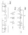
- FIG. 6is a block diagram of another primary GPS repeater used in the GPS repeater systems of FIGS. 1 and 2 ;
- FIG. 7is a block diagram of one embodiment of a gain block used in the primary GPS repeater of FIG. 6 ;
- FIG. 8is a block diagram of a secondary GPS repeater used in the GPS repeater system of FIG. 2 ;
- FIG. 9is a block diagram of one embodiment of a gain block used in the secondary GPS repeater of FIG. 8 .
- the antenna system 5for retransmitting a GPS signal 6 inside a structure 10 .
- the antenna system 5includes a link antenna 12 for receiving the GPS signal 6 from a GPS transmitting antenna 8 , a GPS repeater 14 for amplifying the received GPS signal 7 to produce a second GPS signal 15 and a broadcast antenna 16 for retransmitting the second GPS signal 15 inside the structure 10 .
- This embodimentworks best where the structure 10 has the dimensions of a two-story building.
- the GPS repeater 14feeds the received GPS signal 7 into the structure 10 .
- the external link antenna 12captures the GPS signal 6 and feeds it to the GPS repeater 14 .
- the GPS repeater 14boosts the received GPS signal 7 and drives an internal broadcast antenna 16 that radiates the second GPS signal 15 inside the structure 10 .
- the present inventionovercomes the inability of GPS receivers to work inside a structure, which is a major shortcoming of the Global Positioning System.
- GPSGlobal Positioning System
- Examples of commercial uses of the GPSinclude: Enhanced 911 service; wireless phone services that provide an Internet connection; wireless services that provide the location of, e.g., hotels, restaurants, and businesses; services that provide assistance to the elderly and handicapped; and locator services (provide by, e.g., rental car companies) that provide location information that can be received inside structures such as parking garages, buildings and tunnels.
- the GPS repeater 14includes the components shown in FIG. 3 . Those components include a band pass filter 18 , a low noise amplifier 20 , a gain block 22 , a power amp 24 and second band pass filter 26 .
- the band pass filters 18 and 26are selected so as to reduce the out-of-band signals. For a GPS repeater system, the pass band will usually be around 1575.42 MHz (+/ ⁇ 500 kHz).
- the gain block 22includes a radio frequency (RF) amplifier 28 , a band pass filter 30 and a second RF amplifier 32 , as shown in FIG. 4 .
- RFradio frequency
- the gain block 22includes a mixer 34 for down converting the GPS signal 7 to an intermediate frequency (IF) signal 36 .
- the GPS signal 7is combined by a mixer 34 with a local oscillator (LO) signal 40 to produce the IF signal 36 .
- the IFis between about 140 MHz to 160 MHz, depending on the application. Thus, where the LO signal 40 is 1640 MHz and the GPS signal 7 is 1.5 GHz, then the IF signal would be 140 MHz.
- the IF signal 36is amplified by amplifiers 42 and filtered by a band pass filter 44 .
- the band pass filter 44significantly reduces the complex components or images of the GPS signal 7 and the LO signal 40 .
- a second mixer 46converts the IF signal 36 to produce the RF signal 38 .
- the IF signal 36is combined by the second mixer 46 with the LO signal 40 to produce the RF signal 38 .
- the IFis between about 140 MHz to 160 MHz, depending on the application.
- the LO signal 40is 1640 MHz and the IF signal is 140 MHz, then the RF signal 38 is 1.5 GHz. Therefore, in this embodiment, the RF signal 38 is the second GPS signal 15 .
- the RF signal 38is an unlicensed frequency signal.
- the unlicensed frequency signalcan be in any frequency range not licensed by the Federal Communications Commission (FCC). Some examples of unlicensed frequency bands include: 902–928 MHz and 2.4 GHz.
- the antenna system 105for retransmitting a received GPS signal 107 inside a structure 110 .
- the antenna system 105includes a link antenna 112 for receiving the GPS signal 107 , a primary GPS repeater 114 for amplifying the GPS signal 107 to produce an RF signal 138 , a first broadcast antenna 116 to broadcast the RF signal 138 to one or more secondary repeaters 250 located to cover the intended coverage area inside the structure 110 .
- the RF signal 138is broadcast to the secondary repeater(s) 250 at either the original GPS frequency or another available frequency.
- the RF signal 138is in one of the unlicensed frequency bands such as the Instrumentation, Scientific and Medical (ISM) frequency band of 902 MHz–928 MHz.
- ISMInstrumentation, Scientific and Medical
- Each secondary repeater 250receives the RF signal 138 via a link antenna 113 , amplifies the RF signal 138 to produce a second GPS signal 115 and retransmits the second GPS signal 115 via a second broadcast antenna 117 inside the structure 110 .
- the secondary repeater(s) 250may be placed inside the structure 110 or even placed external to the structure 110 such that the RF signal 138 can be retransmitted into the structure through the windows or walls of the structure. This embodiment works best where the structure 110 has the dimensions of a multi-story building.
- the primary repeater 114includes the components shown in FIG. 6 . Those components include a band pass filter 1118 , a low noise amplifier 120 , a gain block 122 , a power amp 124 and second band pass filter 126 .
- the gain block 122includes, as shown in FIG. 7 , a mixer 152 for down converting the GPS signal 107 to an IF signal 154 .
- the GPS signal 107is combined by a mixer 152 with a local oscillator (LO) signal 140 to produce the IF signal 154 .
- the IFis between about 140 MHz to 160 MHz, depending on the application.
- the IF signal 140is 1640 MHz and the GPS signal 107 is 1.5 GHz, then the IF signal would be 140 MHz.
- the IF signal 154is amplified by amplifiers 156 and filtered by a band pass filter 162 .
- the band pass filter 162significantly reduces the complex components or images of the GPS signal 107 and the LO signal 140 .
- a second mixer 158up converts the IF signal 154 to produce the RF signal 138 .
- the IF signal 154is combined by the second mixer 158 with a second LO signal 164 to produce the RF signal 138 .
- the IFis between about 140 MHz to 160 MHz, depending on the application.
- the second LO signal 164is 762 MHz and the IF signal is 140 MHz, then the RF signal 138 is 902 MHz.
- the secondary repeater 250includes the components shown in FIG. 8 . Those components include a band pass filter 218 , a low noise amplifier 220 , a gain block 222 , a power amp 224 and second band pass filter 226 .
- the gain block 222includes, as shown in FIG. 9 , a mixer 270 for down converting the RF signal 138 to an IF signal 272 .
- the RF signal 138is combined by a mixer 270 with a local oscillator (LO) signal 278 to produce the IF signal 272 .
- the IFis between about 140 MHz to 160 MHz, depending on the application.
- the IF signal 272is amplified by amplifiers 274 and filtered by a band pass filter 276 .
- the band pass filter 276significantly reduces the complex components or images of the RF signal 138 and the first LO signal 278 .
- a second mixer 280converts the IF signal 272 to produce the second GPS signal 215 .
- the IF signal 272is combined by the second mixer 280 with a second LO signal 282 to produce the second GPS signal 215 .
- the IFis between about 140 MHz to 160 MHz, depending on the application.
- the second LO signal 282is 1340 MHz and the IF signal is 160 MHz, then the second GPS signal 215 is 1.5 GHz.
- the amplifierscomprise relatively low power, linear integrated circuit chip components, such as monolithic microwave integrated circuit (MMIC) chips.
- MMICmonolithic microwave integrated circuit
- These chipsmay comprise chips made by the Gallium Arsenide (GaAs) heterojunction transistor manufacturing process.
- GaAsGallium Arsenide
- silicon process chips or CMOS process chipsmight also be utilized.
- MMIC power amplifier chipsSome examples of MMIC power amplifier chips are as follows:
- RF MicrodevicesPCS linear power amplifier RF 2125P, RF 2125, RF 2126 or RF 2146, RF Micro Devices, Inc., 7625 Thorndike Road, Greensboro, N.C. 27409, or 7341-D W. Friendly Ave., Greensboro, N.C. 27410;
- Pacific Monolithics PM 2112 single supply RF IC power amplifierPacific Monolithics, Inc., 1308 Moffett Park Drive, Sunnyvale, Calif.;
- the GPS repeater system of the present inventionfills the GPS null or “blank” areas within structures. In this way, the GPS can be used to locate individuals inside buildings, tunnels, garages, etc.
- the repeater system of the present inventionis used in satellite transmission applications such as digital radio.
- satellite transmission applicationssuch as digital radio.
- digital radio signals transmitted by satellitescan be obstructed from receiving antennas by structures such as buildings, car garages, tunnels, etc. Therefore, the claimed repeater is capable of retransmitting a satellite signal inside a structure such that an uninterrupted satellite signal can be transmitted to a receiver.
Landscapes
- Engineering & Computer Science (AREA)
- Computer Networks & Wireless Communication (AREA)
- Physics & Mathematics (AREA)
- General Physics & Mathematics (AREA)
- Signal Processing (AREA)
- Radar, Positioning & Navigation (AREA)
- Remote Sensing (AREA)
- Astronomy & Astrophysics (AREA)
- Aviation & Aerospace Engineering (AREA)
- Radio Relay Systems (AREA)
Abstract
Description
Claims (21)
Priority Applications (9)
| Application Number | Priority Date | Filing Date | Title |
|---|---|---|---|
| US09/513,543US7068973B1 (en) | 2000-02-25 | 2000-02-25 | Method and apparatus for retransmitting received satellite signals inside a structure |
| AU2001234463AAU2001234463A1 (en) | 2000-01-14 | 2001-01-16 | Repeaters for wireless communication systems |
| CA002397430ACA2397430A1 (en) | 2000-01-14 | 2001-01-16 | Repeaters for wireless communication systems |
| PCT/US2001/001446WO2001052447A2 (en) | 2000-01-14 | 2001-01-16 | Repeaters for wireless communication systems |
| US10/181,109US7577398B2 (en) | 2000-01-14 | 2001-01-16 | Repeaters for wireless communication systems |
| US12/538,508US8010042B2 (en) | 1999-07-20 | 2009-08-10 | Repeaters for wireless communication systems |
| US13/220,541US8358970B2 (en) | 1999-07-20 | 2011-08-29 | Repeaters for wireless communication systems |
| US13/745,540US8630581B2 (en) | 1999-07-20 | 2013-01-18 | Repeaters for wireless communication systems |
| US14/153,871US8971796B2 (en) | 1999-07-20 | 2014-01-13 | Repeaters for wireless communication systems |
Applications Claiming Priority (1)
| Application Number | Priority Date | Filing Date | Title |
|---|---|---|---|
| US09/513,543US7068973B1 (en) | 2000-02-25 | 2000-02-25 | Method and apparatus for retransmitting received satellite signals inside a structure |
Related Parent Applications (1)
| Application Number | Title | Priority Date | Filing Date |
|---|---|---|---|
| US09/506,245Continuation-In-PartUS6445904B1 (en) | 1999-07-20 | 2000-02-17 | Repeater diversity system |
Related Child Applications (1)
| Application Number | Title | Priority Date | Filing Date |
|---|---|---|---|
| PCT/US2001/001446Continuation-In-PartWO2001052447A2 (en) | 1999-07-20 | 2001-01-16 | Repeaters for wireless communication systems |
Publications (1)
| Publication Number | Publication Date |
|---|---|
| US7068973B1true US7068973B1 (en) | 2006-06-27 |
Family
ID=36600593
Family Applications (1)
| Application Number | Title | Priority Date | Filing Date |
|---|---|---|---|
| US09/513,543Expired - LifetimeUS7068973B1 (en) | 1999-07-20 | 2000-02-25 | Method and apparatus for retransmitting received satellite signals inside a structure |
Country Status (1)
| Country | Link |
|---|---|
| US (1) | US7068973B1 (en) |
Cited By (14)
| Publication number | Priority date | Publication date | Assignee | Title |
|---|---|---|---|---|
| US20030123401A1 (en)* | 2001-11-20 | 2003-07-03 | Dean Richard F. | Reverse link power controlled repeater |
| US20030151387A1 (en)* | 2001-03-27 | 2003-08-14 | General Electric Company | Hybrid energy off highway vehicle electric power management system and method |
| US20040147221A1 (en)* | 2002-11-08 | 2004-07-29 | Leonid Sheynblat | Apparatus and method for determining the location of a repeater |
| EP1895681A1 (en)* | 2006-09-04 | 2008-03-05 | E-Blink | System for wireless transmission of data from a base station to a relay station in a cellular telephone network |
| US20080062906A1 (en)* | 2004-04-05 | 2008-03-13 | Kenneth Baker | Repeater that Reports Detected Neighbors |
| US20080225929A1 (en)* | 2007-03-02 | 2008-09-18 | Qualcomm Incorporated | Closed Form Calculation of Temporal Equalizer Weights Used in a Repeater Transmitter Leakage Cancellation System |
| US20100073225A1 (en)* | 2008-09-22 | 2010-03-25 | Wintecronics Ltd. | Two-way radio handheld transceiver capable of wireless reception and transmission of location information associated therewith, and system including the same |
| US7778596B2 (en) | 2004-07-29 | 2010-08-17 | Qualcomm Incorporated | Airlink sensing watermarking repeater |
| US8010042B2 (en) | 1999-07-20 | 2011-08-30 | Andrew Llc | Repeaters for wireless communication systems |
| CN103080772A (en)* | 2010-07-06 | 2013-05-01 | 伽利略卫星导航有限公司 | Indoor satellite navigation system |
| US9118380B2 (en) | 2004-04-05 | 2015-08-25 | Qualcomm Incorporated | Repeater with positioning capabilities |
| US9320040B2 (en) | 2010-02-26 | 2016-04-19 | E-Blink | Method and device for sending/receiving electromagnetic signals received/sent on one or more first frequency bands |
| US9979532B2 (en)* | 2010-08-26 | 2018-05-22 | Golba Llc | Method and system for distributed communication |
| US10009790B2 (en) | 2012-05-04 | 2018-06-26 | EBlink NV | Wide area transport networks for mobile radio access networks and methods of use |
Citations (8)
| Publication number | Priority date | Publication date | Assignee | Title |
|---|---|---|---|---|
| US4972346A (en)* | 1987-03-24 | 1990-11-20 | Mitsubishi Denki Kabushiki Kaisha | High-frequency signal booster |
| EP0559557A1 (en)* | 1992-03-02 | 1993-09-08 | Societe Nouvelle D'equipement Du Calvados | System for radiolocalisation, especially for tracking trajectories of meteorological balloons |
| US5628049A (en)* | 1994-08-29 | 1997-05-06 | Nec Corporation | Mobile satellite terminal equipment |
| US5825327A (en) | 1996-03-08 | 1998-10-20 | Snaptrack, Inc. | GPS receivers and garments containing GPS receivers and methods for using these GPS receivers |
| US5831574A (en) | 1996-03-08 | 1998-11-03 | Snaptrack, Inc. | Method and apparatus for determining the location of an object which may have an obstructed view of the sky |
| US5937332A (en)* | 1997-03-21 | 1999-08-10 | Ericsson, Inc. | Satellite telecommunications repeaters and retransmission methods |
| US6052558A (en)* | 1997-04-28 | 2000-04-18 | Motorola, Inc. | Networked repeater |
| US6134437A (en)* | 1997-06-13 | 2000-10-17 | Ericsson Inc. | Dual-mode satellite/cellular phone architecture with physically separable mode |
- 2000
- 2000-02-25USUS09/513,543patent/US7068973B1/ennot_activeExpired - Lifetime
Patent Citations (8)
| Publication number | Priority date | Publication date | Assignee | Title |
|---|---|---|---|---|
| US4972346A (en)* | 1987-03-24 | 1990-11-20 | Mitsubishi Denki Kabushiki Kaisha | High-frequency signal booster |
| EP0559557A1 (en)* | 1992-03-02 | 1993-09-08 | Societe Nouvelle D'equipement Du Calvados | System for radiolocalisation, especially for tracking trajectories of meteorological balloons |
| US5628049A (en)* | 1994-08-29 | 1997-05-06 | Nec Corporation | Mobile satellite terminal equipment |
| US5825327A (en) | 1996-03-08 | 1998-10-20 | Snaptrack, Inc. | GPS receivers and garments containing GPS receivers and methods for using these GPS receivers |
| US5831574A (en) | 1996-03-08 | 1998-11-03 | Snaptrack, Inc. | Method and apparatus for determining the location of an object which may have an obstructed view of the sky |
| US5937332A (en)* | 1997-03-21 | 1999-08-10 | Ericsson, Inc. | Satellite telecommunications repeaters and retransmission methods |
| US6052558A (en)* | 1997-04-28 | 2000-04-18 | Motorola, Inc. | Networked repeater |
| US6134437A (en)* | 1997-06-13 | 2000-10-17 | Ericsson Inc. | Dual-mode satellite/cellular phone architecture with physically separable mode |
Non-Patent Citations (1)
| Title |
|---|
| "An Introduction to SnapTrack(TM) Server-Aided GPS Technology" (11 pages); source: www.snaptrackinc.com. |
Cited By (41)
| Publication number | Priority date | Publication date | Assignee | Title |
|---|---|---|---|---|
| US8010042B2 (en) | 1999-07-20 | 2011-08-30 | Andrew Llc | Repeaters for wireless communication systems |
| US8971796B2 (en) | 1999-07-20 | 2015-03-03 | Andrew Llc | Repeaters for wireless communication systems |
| US8630581B2 (en) | 1999-07-20 | 2014-01-14 | Andrew Llc | Repeaters for wireless communication systems |
| US8358970B2 (en) | 1999-07-20 | 2013-01-22 | Andrew Corporation | Repeaters for wireless communication systems |
| US20030151387A1 (en)* | 2001-03-27 | 2003-08-14 | General Electric Company | Hybrid energy off highway vehicle electric power management system and method |
| US7924751B2 (en) | 2001-11-20 | 2011-04-12 | Qualcomm Incorporated | Reverse link power controlled repeater |
| US20030123401A1 (en)* | 2001-11-20 | 2003-07-03 | Dean Richard F. | Reverse link power controlled repeater |
| US8665774B2 (en) | 2001-11-20 | 2014-03-04 | Qualcomm Incorporated | Reverse link power-controlled repeater |
| US20040147221A1 (en)* | 2002-11-08 | 2004-07-29 | Leonid Sheynblat | Apparatus and method for determining the location of a repeater |
| US20050208889A1 (en)* | 2002-11-08 | 2005-09-22 | Kenneth Baker | Repeater with positioning capabilities |
| US7457584B2 (en) | 2002-11-08 | 2008-11-25 | Qualcomm Incorporated | Repeater with positioning capabilities |
| US7831263B2 (en)* | 2002-11-08 | 2010-11-09 | Qualcomm Incorporated | Apparatus and method for determining the location of a repeater |
| US9118380B2 (en) | 2004-04-05 | 2015-08-25 | Qualcomm Incorporated | Repeater with positioning capabilities |
| US8514764B2 (en) | 2004-04-05 | 2013-08-20 | Qualcomm Incorporated | Repeater that reports detected neighbors |
| US20080062906A1 (en)* | 2004-04-05 | 2008-03-13 | Kenneth Baker | Repeater that Reports Detected Neighbors |
| US7778596B2 (en) | 2004-07-29 | 2010-08-17 | Qualcomm Incorporated | Airlink sensing watermarking repeater |
| EP1895681A1 (en)* | 2006-09-04 | 2008-03-05 | E-Blink | System for wireless transmission of data from a base station to a relay station in a cellular telephone network |
| US8116239B2 (en) | 2007-03-02 | 2012-02-14 | Qualcomm Incorporated | Use of a filterbank in an adaptive on-channel repeater utilizing adaptive antenna arrays |
| US20080225930A1 (en)* | 2007-03-02 | 2008-09-18 | Qualcomm Incorporated | Use of a Filterbank in an Adaptive On-Channel Repeater Utilizing Adaptive Antenna Arrays |
| US7911985B2 (en) | 2007-03-02 | 2011-03-22 | Qualcomm Incorporated | Automatic gain control and filtering techniques for use in on-channel repeater |
| US7907891B2 (en) | 2007-03-02 | 2011-03-15 | Qualcomm Incorporated | Physical layer repeater utilizing real time measurement metrics and adaptive antenna array to promote signal integrity and amplification |
| US7907513B2 (en) | 2007-03-02 | 2011-03-15 | Qualcomm Incorporated | Superimposed composite channel filter |
| US20080225929A1 (en)* | 2007-03-02 | 2008-09-18 | Qualcomm Incorporated | Closed Form Calculation of Temporal Equalizer Weights Used in a Repeater Transmitter Leakage Cancellation System |
| US8121535B2 (en) | 2007-03-02 | 2012-02-21 | Qualcomm Incorporated | Configuration of a repeater |
| US20080311848A1 (en)* | 2007-03-02 | 2008-12-18 | Qualcomm Incorporated | Configuration of a Repeater |
| US20080225758A1 (en)* | 2007-03-02 | 2008-09-18 | Qualcomm Incorporated | Automatic Gain Control and Filtering Techniques for Use in On-Channel Repeater |
| US20080232241A1 (en)* | 2007-03-02 | 2008-09-25 | Qualcomm Incorporated | Superimposed Composite Channel Filter |
| US8599906B2 (en) | 2007-03-02 | 2013-12-03 | Qualcomm Incorporated | Closed form calculation of temporal equalizer weights used in a repeater transmitter leakage cancellation system |
| US20080225775A1 (en)* | 2007-03-02 | 2008-09-18 | Qualcomm Incorporated | Physical Layer Repeater Utilizing Real Time Measurement Metrics and Adaptive Antenna Array to Promote Signal Integrity and Amplification |
| US8619837B2 (en) | 2007-03-02 | 2013-12-31 | Qualcomm Incorporated | Use of adaptive antenna array in conjunction with an on-channel repeater to improve signal quality |
| US20080225931A1 (en)* | 2007-03-02 | 2008-09-18 | Qualcomm Incorporated | Use of Adaptive Antenna Array in Conjunction with an On-Channel Repeater to Improve Signal Quality |
| US20100073225A1 (en)* | 2008-09-22 | 2010-03-25 | Wintecronics Ltd. | Two-way radio handheld transceiver capable of wireless reception and transmission of location information associated therewith, and system including the same |
| US9320040B2 (en) | 2010-02-26 | 2016-04-19 | E-Blink | Method and device for sending/receiving electromagnetic signals received/sent on one or more first frequency bands |
| EP2591379A4 (en)* | 2010-07-06 | 2013-12-11 | Galileo Satellite Navigation Ltd | INTERIOR SATELLITE NAVIGATION SYSTEM |
| CN103080772A (en)* | 2010-07-06 | 2013-05-01 | 伽利略卫星导航有限公司 | Indoor satellite navigation system |
| CN103080772B (en)* | 2010-07-06 | 2015-10-07 | 伽利略卫星导航有限公司 | Indoor satellite navigation system |
| US9979532B2 (en)* | 2010-08-26 | 2018-05-22 | Golba Llc | Method and system for distributed communication |
| US11283585B2 (en) | 2010-08-26 | 2022-03-22 | Golba Llc | Method and system for distributed communication |
| US11664965B2 (en) | 2010-08-26 | 2023-05-30 | Golba Llc | Method and system for distributed communication |
| US11924147B2 (en) | 2010-08-26 | 2024-03-05 | Golba Llc | Method and system for distributed communication |
| US10009790B2 (en) | 2012-05-04 | 2018-06-26 | EBlink NV | Wide area transport networks for mobile radio access networks and methods of use |
Similar Documents
| Publication | Publication Date | Title |
|---|---|---|
| US7068973B1 (en) | Method and apparatus for retransmitting received satellite signals inside a structure | |
| US7139580B2 (en) | Method and apparatus for estimating the position of a terminal based on identification codes for transmission sources | |
| JP3352954B2 (en) | Wireless terminal | |
| US6806830B2 (en) | Electronic device precision location via local broadcast signals | |
| JP4364121B2 (en) | Reduction of mutual interference in combined GPS receiver and communication system | |
| US8750925B2 (en) | Voice data RF GPS integrated circuit | |
| US6615021B1 (en) | Method and apparatus for transmitting radio frequency signals to and from a pager | |
| JP3294202B2 (en) | Satellite positioning assistance system | |
| CN1781257B (en) | Improving performance of a receiver in an interference environment | |
| EP1071160A2 (en) | Repeater with side-to-side arranged antennas and with adaptive feedback signal cancellation circuit | |
| US7729656B2 (en) | Cellular network low noise amplifiers for use with multiple frequencies | |
| US6154656A (en) | Wireless communication device and system incorporating location-determining means | |
| AU2019386760B2 (en) | RTK base station apparatus and signal interaction system and method | |
| US10228469B2 (en) | Reception device | |
| JP2003298486A (en) | Radio relaying system | |
| WO2021183067A1 (en) | A gnss repeater architecture and location finding method for indoor positioning systems using lower frequencies than gnss signals | |
| US20080218427A1 (en) | Multiple mode RF communication system | |
| US20250211279A1 (en) | Terminal Device | |
| US20050206567A1 (en) | System for transmitting a signal for positioning and method for producing the system | |
| CN118573257A (en) | Variable-frequency wireless blind supplementing system based on public network mobile signals | |
| US20030048228A1 (en) | Antenna device using in a shielded environment | |
| JP2007218651A (en) | Retransmission device for positioning signal | |
| JP4050645B2 (en) | Satellite signal receiving antenna, satellite signal receiving system, and satellite signal retransmission system | |
| US6643509B1 (en) | Civil aviation communication system | |
| US7746274B2 (en) | Global positioning receiver with PN code output |
Legal Events
| Date | Code | Title | Description |
|---|---|---|---|
| AS | Assignment | Owner name:ANDREW CORPORATION, ILLINOIS Free format text:ASSIGNMENT OF ASSIGNORS INTEREST;ASSIGNORS:LOVINGGOOD, BRECK W.;TENNANT, DAVID T.;REEL/FRAME:010637/0341;SIGNING DATES FROM 20000216 TO 20000221 | |
| STCF | Information on status: patent grant | Free format text:PATENTED CASE | |
| AS | Assignment | Owner name:BANK OF AMERICA, N.A., AS ADMINISTRATIVE AGENT, CA Free format text:SECURITY AGREEMENT;ASSIGNORS:COMMSCOPE, INC. OF NORTH CAROLINA;ALLEN TELECOM, LLC;ANDREW CORPORATION;REEL/FRAME:020362/0241 Effective date:20071227 Owner name:BANK OF AMERICA, N.A., AS ADMINISTRATIVE AGENT,CAL Free format text:SECURITY AGREEMENT;ASSIGNORS:COMMSCOPE, INC. OF NORTH CAROLINA;ALLEN TELECOM, LLC;ANDREW CORPORATION;REEL/FRAME:020362/0241 Effective date:20071227 | |
| AS | Assignment | Owner name:ANDREW LLC, NORTH CAROLINA Free format text:CHANGE OF NAME;ASSIGNOR:ANDREW CORPORATION;REEL/FRAME:021805/0044 Effective date:20080827 | |
| FPAY | Fee payment | Year of fee payment:4 | |
| AS | Assignment | Owner name:COMMSCOPE, INC. OF NORTH CAROLINA, NORTH CAROLINA Free format text:PATENT RELEASE;ASSIGNOR:BANK OF AMERICA, N.A., AS ADMINISTRATIVE AGENT;REEL/FRAME:026039/0005 Effective date:20110114 Owner name:ALLEN TELECOM LLC, NORTH CAROLINA Free format text:PATENT RELEASE;ASSIGNOR:BANK OF AMERICA, N.A., AS ADMINISTRATIVE AGENT;REEL/FRAME:026039/0005 Effective date:20110114 Owner name:ANDREW LLC (F/K/A ANDREW CORPORATION), NORTH CAROL Free format text:PATENT RELEASE;ASSIGNOR:BANK OF AMERICA, N.A., AS ADMINISTRATIVE AGENT;REEL/FRAME:026039/0005 Effective date:20110114 | |
| AS | Assignment | Owner name:JPMORGAN CHASE BANK, N.A., AS COLLATERAL AGENT, NE Free format text:SECURITY AGREEMENT;ASSIGNORS:ALLEN TELECOM LLC, A DELAWARE LLC;ANDREW LLC, A DELAWARE LLC;COMMSCOPE, INC. OF NORTH CAROLINA, A NORTH CAROLINA CORPORATION;REEL/FRAME:026276/0363 Effective date:20110114 | |
| AS | Assignment | Owner name:JPMORGAN CHASE BANK, N.A., AS COLLATERAL AGENT, NE Free format text:SECURITY AGREEMENT;ASSIGNORS:ALLEN TELECOM LLC, A DELAWARE LLC;ANDREW LLC, A DELAWARE LLC;COMMSCOPE, INC OF NORTH CAROLINA, A NORTH CAROLINA CORPORATION;REEL/FRAME:026272/0543 Effective date:20110114 | |
| FPAY | Fee payment | Year of fee payment:8 | |
| AS | Assignment | Owner name:COMMSCOPE TECHNOLOGIES LLC, NORTH CAROLINA Free format text:CHANGE OF NAME;ASSIGNOR:ANDREW LLC;REEL/FRAME:035283/0849 Effective date:20150301 | |
| AS | Assignment | Owner name:WILMINGTON TRUST, NATIONAL ASSOCIATION, AS COLLATERAL AGENT, CONNECTICUT Free format text:SECURITY INTEREST;ASSIGNORS:ALLEN TELECOM LLC;COMMSCOPE TECHNOLOGIES LLC;COMMSCOPE, INC. OF NORTH CAROLINA;AND OTHERS;REEL/FRAME:036201/0283 Effective date:20150611 Owner name:WILMINGTON TRUST, NATIONAL ASSOCIATION, AS COLLATE Free format text:SECURITY INTEREST;ASSIGNORS:ALLEN TELECOM LLC;COMMSCOPE TECHNOLOGIES LLC;COMMSCOPE, INC. OF NORTH CAROLINA;AND OTHERS;REEL/FRAME:036201/0283 Effective date:20150611 | |
| AS | Assignment | Owner name:COMMSCOPE, INC. OF NORTH CAROLINA, NORTH CAROLINA Free format text:RELEASE OF SECURITY INTEREST PATENTS (RELEASES RF 036201/0283);ASSIGNOR:WILMINGTON TRUST, NATIONAL ASSOCIATION;REEL/FRAME:042126/0434 Effective date:20170317 Owner name:COMMSCOPE TECHNOLOGIES LLC, NORTH CAROLINA Free format text:RELEASE OF SECURITY INTEREST PATENTS (RELEASES RF 036201/0283);ASSIGNOR:WILMINGTON TRUST, NATIONAL ASSOCIATION;REEL/FRAME:042126/0434 Effective date:20170317 Owner name:REDWOOD SYSTEMS, INC., NORTH CAROLINA Free format text:RELEASE OF SECURITY INTEREST PATENTS (RELEASES RF 036201/0283);ASSIGNOR:WILMINGTON TRUST, NATIONAL ASSOCIATION;REEL/FRAME:042126/0434 Effective date:20170317 Owner name:ALLEN TELECOM LLC, NORTH CAROLINA Free format text:RELEASE OF SECURITY INTEREST PATENTS (RELEASES RF 036201/0283);ASSIGNOR:WILMINGTON TRUST, NATIONAL ASSOCIATION;REEL/FRAME:042126/0434 Effective date:20170317 | |
| MAFP | Maintenance fee payment | Free format text:PAYMENT OF MAINTENANCE FEE, 12TH YEAR, LARGE ENTITY (ORIGINAL EVENT CODE: M1553) Year of fee payment:12 | |
| AS | Assignment | Owner name:COMMSCOPE, INC. OF NORTH CAROLINA, NORTH CAROLINA Free format text:RELEASE BY SECURED PARTY;ASSIGNOR:JPMORGAN CHASE BANK, N.A.;REEL/FRAME:048840/0001 Effective date:20190404 Owner name:COMMSCOPE TECHNOLOGIES LLC, NORTH CAROLINA Free format text:RELEASE BY SECURED PARTY;ASSIGNOR:JPMORGAN CHASE BANK, N.A.;REEL/FRAME:048840/0001 Effective date:20190404 Owner name:ALLEN TELECOM LLC, ILLINOIS Free format text:RELEASE BY SECURED PARTY;ASSIGNOR:JPMORGAN CHASE BANK, N.A.;REEL/FRAME:048840/0001 Effective date:20190404 Owner name:ANDREW LLC, NORTH CAROLINA Free format text:RELEASE BY SECURED PARTY;ASSIGNOR:JPMORGAN CHASE BANK, N.A.;REEL/FRAME:048840/0001 Effective date:20190404 Owner name:REDWOOD SYSTEMS, INC., NORTH CAROLINA Free format text:RELEASE BY SECURED PARTY;ASSIGNOR:JPMORGAN CHASE BANK, N.A.;REEL/FRAME:048840/0001 Effective date:20190404 Owner name:REDWOOD SYSTEMS, INC., NORTH CAROLINA Free format text:RELEASE BY SECURED PARTY;ASSIGNOR:JPMORGAN CHASE BANK, N.A.;REEL/FRAME:049260/0001 Effective date:20190404 Owner name:ANDREW LLC, NORTH CAROLINA Free format text:RELEASE BY SECURED PARTY;ASSIGNOR:JPMORGAN CHASE BANK, N.A.;REEL/FRAME:049260/0001 Effective date:20190404 Owner name:ALLEN TELECOM LLC, ILLINOIS Free format text:RELEASE BY SECURED PARTY;ASSIGNOR:JPMORGAN CHASE BANK, N.A.;REEL/FRAME:049260/0001 Effective date:20190404 Owner name:COMMSCOPE, INC. OF NORTH CAROLINA, NORTH CAROLINA Free format text:RELEASE BY SECURED PARTY;ASSIGNOR:JPMORGAN CHASE BANK, N.A.;REEL/FRAME:049260/0001 Effective date:20190404 Owner name:COMMSCOPE TECHNOLOGIES LLC, NORTH CAROLINA Free format text:RELEASE BY SECURED PARTY;ASSIGNOR:JPMORGAN CHASE BANK, N.A.;REEL/FRAME:049260/0001 Effective date:20190404 | |
| AS | Assignment | Owner name:JPMORGAN CHASE BANK, N.A., NEW YORK Free format text:ABL SECURITY AGREEMENT;ASSIGNORS:COMMSCOPE, INC. OF NORTH CAROLINA;COMMSCOPE TECHNOLOGIES LLC;ARRIS ENTERPRISES LLC;AND OTHERS;REEL/FRAME:049892/0396 Effective date:20190404 Owner name:JPMORGAN CHASE BANK, N.A., NEW YORK Free format text:TERM LOAN SECURITY AGREEMENT;ASSIGNORS:COMMSCOPE, INC. OF NORTH CAROLINA;COMMSCOPE TECHNOLOGIES LLC;ARRIS ENTERPRISES LLC;AND OTHERS;REEL/FRAME:049905/0504 Effective date:20190404 Owner name:WILMINGTON TRUST, NATIONAL ASSOCIATION, AS COLLATE Free format text:PATENT SECURITY AGREEMENT;ASSIGNOR:COMMSCOPE TECHNOLOGIES LLC;REEL/FRAME:049892/0051 Effective date:20190404 Owner name:WILMINGTON TRUST, NATIONAL ASSOCIATION, AS COLLATERAL AGENT, CONNECTICUT Free format text:PATENT SECURITY AGREEMENT;ASSIGNOR:COMMSCOPE TECHNOLOGIES LLC;REEL/FRAME:049892/0051 Effective date:20190404 | |
| AS | Assignment | Owner name:RUCKUS WIRELESS, LLC (F/K/A RUCKUS WIRELESS, INC.), NORTH CAROLINA Free format text:RELEASE OF SECURITY INTEREST AT REEL/FRAME 049905/0504;ASSIGNOR:JPMORGAN CHASE BANK, N.A., AS COLLATERAL AGENT;REEL/FRAME:071477/0255 Effective date:20241217 Owner name:COMMSCOPE TECHNOLOGIES LLC, NORTH CAROLINA Free format text:RELEASE OF SECURITY INTEREST AT REEL/FRAME 049905/0504;ASSIGNOR:JPMORGAN CHASE BANK, N.A., AS COLLATERAL AGENT;REEL/FRAME:071477/0255 Effective date:20241217 Owner name:COMMSCOPE, INC. OF NORTH CAROLINA, NORTH CAROLINA Free format text:RELEASE OF SECURITY INTEREST AT REEL/FRAME 049905/0504;ASSIGNOR:JPMORGAN CHASE BANK, N.A., AS COLLATERAL AGENT;REEL/FRAME:071477/0255 Effective date:20241217 Owner name:ARRIS SOLUTIONS, INC., NORTH CAROLINA Free format text:RELEASE OF SECURITY INTEREST AT REEL/FRAME 049905/0504;ASSIGNOR:JPMORGAN CHASE BANK, N.A., AS COLLATERAL AGENT;REEL/FRAME:071477/0255 Effective date:20241217 Owner name:ARRIS TECHNOLOGY, INC., NORTH CAROLINA Free format text:RELEASE OF SECURITY INTEREST AT REEL/FRAME 049905/0504;ASSIGNOR:JPMORGAN CHASE BANK, N.A., AS COLLATERAL AGENT;REEL/FRAME:071477/0255 Effective date:20241217 Owner name:ARRIS ENTERPRISES LLC (F/K/A ARRIS ENTERPRISES, INC.), NORTH CAROLINA Free format text:RELEASE OF SECURITY INTEREST AT REEL/FRAME 049905/0504;ASSIGNOR:JPMORGAN CHASE BANK, N.A., AS COLLATERAL AGENT;REEL/FRAME:071477/0255 Effective date:20241217 |