US7068867B2 - Ultrasonic position indicator - Google Patents
Ultrasonic position indicatorDownload PDFInfo
- Publication number
- US7068867B2 US7068867B2US10/335,703US33570303AUS7068867B2US 7068867 B2US7068867 B2US 7068867B2US 33570303 AUS33570303 AUS 33570303AUS 7068867 B2US7068867 B2US 7068867B2
- Authority
- US
- United States
- Prior art keywords
- instrument
- ultrasound
- signals
- subject
- optical
- Prior art date
- Legal status (The legal status is an assumption and is not a legal conclusion. Google has not performed a legal analysis and makes no representation as to the accuracy of the status listed.)
- Expired - Lifetime
Links
Images


Classifications
- A—HUMAN NECESSITIES
- A61—MEDICAL OR VETERINARY SCIENCE; HYGIENE
- A61B—DIAGNOSIS; SURGERY; IDENTIFICATION
- A61B8/00—Diagnosis using ultrasonic, sonic or infrasonic waves
- A61B8/08—Clinical applications
- A61B8/0833—Clinical applications involving detecting or locating foreign bodies or organic structures
- A61B8/0841—Clinical applications involving detecting or locating foreign bodies or organic structures for locating instruments
- A—HUMAN NECESSITIES
- A61—MEDICAL OR VETERINARY SCIENCE; HYGIENE
- A61B—DIAGNOSIS; SURGERY; IDENTIFICATION
- A61B5/00—Measuring for diagnostic purposes; Identification of persons
- A61B5/0093—Detecting, measuring or recording by applying one single type of energy and measuring its conversion into another type of energy
- A61B5/0095—Detecting, measuring or recording by applying one single type of energy and measuring its conversion into another type of energy by applying light and detecting acoustic waves, i.e. photoacoustic measurements
- A—HUMAN NECESSITIES
- A61—MEDICAL OR VETERINARY SCIENCE; HYGIENE
- A61B—DIAGNOSIS; SURGERY; IDENTIFICATION
- A61B5/00—Measuring for diagnostic purposes; Identification of persons
- A61B5/06—Devices, other than using radiation, for detecting or locating foreign bodies ; Determining position of diagnostic devices within or on the body of the patient
- A61B5/061—Determining position of a probe within the body employing means separate from the probe, e.g. sensing internal probe position employing impedance electrodes on the surface of the body
- A—HUMAN NECESSITIES
- A61—MEDICAL OR VETERINARY SCIENCE; HYGIENE
- A61B—DIAGNOSIS; SURGERY; IDENTIFICATION
- A61B5/00—Measuring for diagnostic purposes; Identification of persons
- A61B5/68—Arrangements of detecting, measuring or recording means, e.g. sensors, in relation to patient
- A61B5/6846—Arrangements of detecting, measuring or recording means, e.g. sensors, in relation to patient specially adapted to be brought in contact with an internal body part, i.e. invasive
- A61B5/6847—Arrangements of detecting, measuring or recording means, e.g. sensors, in relation to patient specially adapted to be brought in contact with an internal body part, i.e. invasive mounted on an invasive device
- A61B5/6852—Catheters
- A—HUMAN NECESSITIES
- A61—MEDICAL OR VETERINARY SCIENCE; HYGIENE
- A61B—DIAGNOSIS; SURGERY; IDENTIFICATION
- A61B8/00—Diagnosis using ultrasonic, sonic or infrasonic waves
- A61B8/08—Clinical applications
- A61B8/0833—Clinical applications involving detecting or locating foreign bodies or organic structures
- A—HUMAN NECESSITIES
- A61—MEDICAL OR VETERINARY SCIENCE; HYGIENE
- A61B—DIAGNOSIS; SURGERY; IDENTIFICATION
- A61B17/00—Surgical instruments, devices or methods
- A61B17/34—Trocars; Puncturing needles
- A61B17/3403—Needle locating or guiding means
- A—HUMAN NECESSITIES
- A61—MEDICAL OR VETERINARY SCIENCE; HYGIENE
- A61B—DIAGNOSIS; SURGERY; IDENTIFICATION
- A61B90/00—Instruments, implements or accessories specially adapted for surgery or diagnosis and not covered by any of the groups A61B1/00 - A61B50/00, e.g. for luxation treatment or for protecting wound edges
- A61B90/36—Image-producing devices or illumination devices not otherwise provided for
- A61B90/37—Surgical systems with images on a monitor during operation
- A61B2090/378—Surgical systems with images on a monitor during operation using ultrasound
- A61B2090/3782—Surgical systems with images on a monitor during operation using ultrasound transmitter or receiver in catheter or minimal invasive instrument
- A61B2090/3788—Surgical systems with images on a monitor during operation using ultrasound transmitter or receiver in catheter or minimal invasive instrument transmitter only
Definitions
- the inventionrelates to imaging internal regions of a subject and more particularly to monitoring positions of instruments inside the subject using ultrasonic imaging.
- Such surgical instrumentsinclude needles, endoscopes (a bundle of optical fibers, or a small camera encapsulated by a catheter), and catheters. These instruments may be used for procedures such as biopsies, endoscopic imaging, and cardiac catheterization surgeries. These procedures are performed, e.g., to diagnose tissues or organs suspected of being cancerous or otherwise in need of treatment, and for treating cardiac disease or malfunction.
- X-Ray fluoroscopySeveral techniques exist for monitoring the position of an instrument inside a human, including X-Ray fluoroscopy.
- Conventional X-Ray fluoroscopyis designed to reduce/minimize X-ray dosage, but long procedures can produce significant doses in the patient. Further, long-term exposure of personnel conducting X-Ray fluoroscopy procedures is a concern.
- metal instrumentsproduce a very strong signal in response to X-rays, saturating detectors and thus producing a “halo” around the instrument's image such that a tip of the instrument may be obscured.
- ultrasound or electromagnetic radiationOther techniques for monitoring instrument position include using ultrasound or electromagnetic radiation.
- Ultrasoundis common because when operated at low power its energy is not hazardous and because soft tissues in the body that contain water are ideal for transmitting and reflecting sound waves.
- An ultrasound imagertransmits sound waves to a specific area in the body and detects reflected signals. The imager forms a gray-scale image where the position of each feature is calculated from the delay in the reflected sound wave, and different intensities of reflected signals appear as different levels of gray in the image.
- a high impedance mismatch between the instrument and the surrounding tissuesresults in strong scattering of the sound waves.
- Another challenge with locating the tip of an instrument using ultrasoundresults from the two-dimensional scanning nature of the ultrasound imaging procedure.
- the operatorcan view the cross section of the instrument in the plane “cut out” by the array. Consequently, only when the instrument is coplanar with the scanning motion can one identify its shape and locate its tip easily; at any other angle only the part of the instrument that is coplanar with the imaged plane can be identified.
- passive and active acoustic reflectors or transducersmay be attached to instruments as discussed in U.S. Pat. No. 4,431,006 and U.S. Pat. No. 4,697,595, respectively.
- Ultrasound transducerscan be integrated with instruments such as a catheter.
- a position sensormay be attached to a needle and convey position information to an imager.
- a low-power RF emittermay be attached to the tip of an instrument and RF sensors outside of the body may be used to detect the position of the emitter.
- Non-concentric coilsmay be attached to an instrument to produce signals in response to externally-applied magnetic fields to allow determination of position and orientation of an instrument attached to the coils.
- ultrasound pulsescan be produced outside of a subject, conveyed to the inside of the subject using acoustical fibers, and reflected signals collected and transmitted with these same fibers.
- the inventionprovides a system for monitoring a position of an instrument in a subject.
- the systemincludes a light transmission medium configured to transmit light pulses to a desired region to produce an acoustic signal, at least one ultrasound sensor configured to receive the acoustic signal and to produce a transduced signal from the acoustic signal, and a processing unit connected to the at least one ultrasound sensor and configured to locate a source of the acoustic signal using the transduced signal.
- the systemfurther includes a photoacoustic transducer including a photoacoustic material disposed in the desired region to absorb light transmitted by the light transmission medium to produce the acoustic signal.
- the light transmission mediumis an optical fiber and the photoacoustic material is disposed at an end of the optical fiber.
- the photoacoustic materialis a first photoacoustic material configured to produce a first frequency of sound from absorbed light
- the systemfurther comprising a second photoacoustic material configured to produce a second frequency of sound from absorbed light and coupled to the fiber distally from the first material, the first photoacoustic material being disposed and configured to absorb a first portion of light transmitted by the light transmission medium and to pass a second portion of the light transmitted by the light transmission medium.
- the optical fiberis coupled to the instrument.
- the end of the optical fiber, on which the photoacoustic material is disposed,is disposed a known distance from an end of the instrument.
- the light transmission mediumcomprises a plurality of optical fibers and the system further comprises position indicators coupled to the plurality of fibers.
- the position indicatorscomprise photoacoustic transducers including different photoacoustic materials configured to produce different frequencies of ultrasound signals, and wherein the processor is configured to distinguish between the photoacoustic transducers in accordance with the respective frequencies associated with the photoacoustic materials.
- the systemfurther includes an optical driver coupled to the processor, wherein the processor is configured to cause the optical driver to provide optical signals to the plurality of optical fibers at different times, and wherein the processor is configured to distinguish between the position indicators in accordance with respective excitation times of the position indicators.
- the systemfurther includes the instrument, wherein the position indicators are coupled to the instrument and have ultrasound-emitting portions that are disposed at least one of at known locations relative to the instrument and at known locations relative to each other.
- the systemfurther includes a sensor disposed among the plurality of position indicators and coupled to the processor, the processor being further configured to determine distances from the sensor to the position indicators in response to information provided to the processor by the sensor.
- the systemfurther includes the instrument, the instrument being further configured to selectively contain the plurality of position indicators and deploy ultrasound-emitting portions of the position indicators outside of the instrument.
- the instrumentcomprises a retractable sleeve for selectively containing and deploying the position indicators.
- the inventionprovides a system for monitoring a position of an instrument in a subject, the instrument being configured to be inserted into the subject.
- the systemincludes an array of ultrasound transducers configured to translate between ultrasound signals and electrical signals, an optical driver configured to provide optical excitation signals, a position indicator including an optical fiber, coupled to the optical driver and attached to the instrument, and a photoacoustic material disposed to absorb light transmitted by the optical fiber, a display configured to provide images in response to control signals, and a processor connected to the transducers, the optical driver, and the display, and configured to: actuate the array to emit ultrasound signals into the subject, receive first electrical signals from the array indicative of reflections of the emitted ultrasound signals, process the first electrical signals into first control signals indicative of a first image of the subject and to convey the first control signals to the display, actuate the driver to provide an excitation signal to the optical fiber, receive a second electrical signal from the array indicative of an ultrasound signal produced by the photoacoustic material, determine a position of the instrument from the
- Implementations of the inventionmay include one or more of the following features.
- the processoris configured to control the display to provide the images from the first and second control signals such that the first and second images at least appear to be provided concurrently.
- the processoris configured to actuate the transmission from the array and to actuate the optical driver at different, alternating times.
- the inventionprovides a method of monitoring a position of a position indicator relative to a subject, the indicator being disposed in a region inside the subject.
- the methodincludes applying first ultrasound signals to a region of the subject, detecting reflected and scattered ultrasound signals from the region of the subject in response to the applied first ultrasound signals, producing a subject image of the region of the subject from the reflected signals, transmitting an excitation signal into the region of the subject to the position indicator to produce another ultrasound signal at a location associated with the position indicator, determining a position of the position indicator from second ultrasound signals related to the other ultrasound signal, producing a position-indicator image from the second ultrasound signals, and superimposing the subject image and the position-indicator image.
- Transmitting the excitation signalcomprises transmitting light through an optical fiber, the method further comprising photoacoustically transducing the light into the another ultrasound signal and emitting the another ultrasound signal from the position indicator.
- the methodfurther includes transmitting light through another optical fiber into the region of the subject to another position indicator, emitting a further ultrasound signal from the another position indicator, distinguishing between third ultrasound signals, related to the further ultrasound signal, and the second ultrasound signals based on at least one of timing of receipt of the second and third signals and frequencies of the second and third signals, and producing another position-indicator image from the third ultrasound signals.
- the methodfurther includes deploying the position indicators from an instrument inserted into a volume in the region of the subject, allowing the position indicators to extend to one of their respective full extensions and into contact with a surface bounding the volume in the region of the subject, moving the instrument within the volume, and producing position-indicator images with the instrument at different positions within the volume.
- the methodfurther includes calculating a volume of the body cavity in which the position indicators are deployed from relative positions of the indicators.
- the body cavityis a chamber of the heart.
- the volumeis calculated separately during diastolic and systolic cycles, the method further comprising calculating cardiac output from a difference in the volume of the chamber during each cardiac cycle.
- Photoacoustically transducing the light into the another ultrasound signalcomprises absorbing the light by a photoacoustic material disposed at a tip of the position indicator.
- Implementations of the inventionmay also include one or more of the following features.
- the other ultrasound signalis produced by absorbing the excitation signal by a portion of the subject in the region.
- the methodfurther includes determining distances from tips of the position indicators to a sensor disposed among the position indicators.
- the methodfurther includes forming an ultrasound image of internal structures of the subject using ultrasound pulses emitted by the position indicators, scattered by the structures, and received by the sensor.
- the inventionprovides an instrument for use with an ultrasound imager for monitoring positions associated with the instrument while the instrument is disposed in a subject.
- the instrumentincludes a body having a proximal end and a distal end, the body being configured to be inserted into the subject, a first optical fiber coupled to the body and having a distal end disposed adjacent to the distal end of the body, and a first photoacoustic material on the first optical fiber configured to transduce optical signals received from the first optical fiber into first ultrasound signals and to emit the first ultrasound signals into the subject.
- Implementations of the inventionmay include one or more of the following features.
- the distal end of the first optical fiberis disposed a known distance from the distal end of the body.
- the instrumentfurther includes a second optical fiber coupled to the body and having a distal end, and a second photoacoustic material on the second optical fiber, the second photoacoustic material configured to transduce optical signals received from the second optical fiber into second ultrasound signals and to emit the second ultrasound signals into the subject, the first and second photoacoustic materials being configured such that frequencies of the first and second ultrasound signals are different.
- the first and second optical fibersare fixedly coupled to the body along portions of their lengths and distal portions of their lengths releasably contained by the body.
- the bodyincludes a sleeve for releasably containing the distal portions of the optical fibers, the sleeve being movable between a first position for containing the distal portions of the fibers and a second position for deploying the distal portions of the fibers.
- the instrumentfurther includes an acoustic sensor, configured to transduce acoustic signals, coupled to the body.
- the bodyis configured to be inserted into a human.
- the inventionprovides a system for monitoring the position of an instrument in a subject, the instrument being configured to be inserted into the subject.
- the systemincludes a plurality of ultrasound transducers configured to translate between ultrasound signals and electrical signals, driver means coupled to the ultrasound transducers for providing first excitation signals to the ultrasound transducers and for providing second excitation signals, position indicator means coupled to the driver and to the instrument for producing ultrasound signals in response to the second excitation signals from the driver means, and processor means, coupled to the transducers and the driver means, for controlling the driver means to cause the transducers to transmit first ultrasound signals into the subject, for determining an image of the subject from reflected subject signals related to the first ultrasound signals, for controlling the driver means to cause the position indicator means to produce a second ultrasound signals, for determining an indicator image corresponding to the position indicator means from indicator signals related to the second ultrasound signal, and for controlling a display to show an association between the indicator image and the image of the subject.
- the driver meansincludes an electrical driver coupled to the transducers and an optical driver coupled to the position indicator means.
- the position indicator meansincludes a photoacoustic material on an optical fiber.
- the position indicator meansincludes multiple optical fibers each having a photoacoustic material on a respective tip. Different optical fibers of the position indicator means have different photoacoustic material characteristics that produce different frequencies of ultrasound.
- the position indicator meanscomprises multiple ultrasound emitters, the system further comprising an acoustic sensor configured to receive and transduce ultrasound from the multiple ultrasound emitters, and to transmit the transduced information to the processing means that is further for determining distances from the acoustic sensor to the multiple ultrasound emitters.
- the inventionprovides a method of monitoring a position of a position indicator relative to a subject, the indicator being disposed in a region inside the subject.
- the methodincludes applying first ultrasound signals to the region of the subject, detecting first reflected ultrasound signals from the region of the subject in response to the applied first ultrasound signals, storing a first image obtained from the first reflected ultrasound signals, applying second ultrasound signals to the region of the subject at a first time, providing an excitation signal to the position indicator at a second time, after the first time, detecting second reflected ultrasound signals and the acoustic signal produced by the position indicator from the region of the subject, storing a second image obtained from the second reflected ultrasound signals and the acoustic signal produced by the position indicator, comparing the first and second images to produce a position-indicator image to isolate the acoustic signal produced by the position indicator, determining the position of the position indicator from the position-indicator image, and superimposing an image of the subject and the position-indicator image.
- Implementations of the inventionmay include one or more of the following features.
- the image of the subject used for the superimposingis the first image, and wherein the comparing comprises subtracting one of the first and second images from the other of the first and second images.
- the image of the subject used for the superimposingis the first image, and wherein the comparing comprises high pass filtering of a difference between the first and second images.
- the inventionprovides a method of monitoring a position of a position indicator relative to a subject, the indicator being disposed in a region inside the subject.
- the methodincludes applying first ultrasound signals to a region of the subject, detecting first reflected ultrasound signals from the region of the subject in response to the applied first ultrasound signals, storing a first image obtained from the first reflected ultrasound signals, applying second ultrasound signals to the region of the subject, detecting the second ultrasound signal at the position indicator, providing an excitation signal to the position indicator to produce an acoustic signal substantially when the second ultrasound signal reaches the position indicator, detecting second reflected ultrasound signals and the acoustic signal produced by the position indicator from the region of the subject, storing a second image obtained from the second reflected ultrasound signals and the acoustic signal produced by the position indicator, comparing the first and second images to produce a position-indicator image to isolate the acoustic signal produced by the position indicator, determining the position of the position indicator from position-indicator image, and superimposing an image of
- Implementations of the inventionmay include one or more of the following features.
- the image of the subject used for the superimposingis the first image, and wherein the comparing comprises subtracting one of the first and second images from the other of the first and second images.
- the image of the subject used for the superimposingis the first image, and wherein the comparing comprises high pass filtering of a difference between the first and second images.
- a low-cost, disposable ultrasound sourcecan be disposed on an instrument inserted into a body for emitting ultrasound that is detectable outside of the body, or at another location within the body.
- An ultrasound sourcecan be provided on a surgical instrument and excited without using electric wires or external attachment to the instrument.
- Surgical instrument positioningcan be determined without being affected by electromagnetic interference. Different tissue types may be identified using a surgical instrument positioning system. Different instruments may be concurrently disposed in a subject and have their respective positions identified independently. The orientation of an instrument relative to body features or fiducial markers can be identified easily. Images of position indicators can be superimposed on/with images of a subject. Volumes/geometries of cavities, vessels, etc.
- FIG. 1is a simplified diagram of an ultrasound system for monitoring a position of a position indicator.
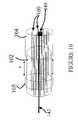
- FIG. 2is a simplified, see-through perspective view of a position indicator disposed in a needle.
- FIG. 3is a simplified, see-through perspective view of a position indicator disposed externally to a needle.
- FIG. 4is a simplified, see-through perspective view of a position indicator disposed in a catheter.
- FIG. 5is a block flow diagram of a process of using the system shown in FIG. 1 .
- FIG. 6is a perspective view of the position indicator shown in FIG. 2 in use.
- FIG. 7is a simplified, see-through perspective view of two position indicators disposed in a needle.
- FIGS. 8–9are simplified, see-through perspective views of multiple position indicators disposed in a catheter with a retractable sleeve, with the sleeve in a closed position and a retracted position, respectively.
- FIG. 10is a simplified, see-through perspective view of multiple position indicators disposed in a catheter with a retractable sleeve, with the sleeve in a closed position, and with a sensor disposed among the indicators.
- FIG. 11is a simplified, cut-away view of a human heart and multiple position indicators disposed in a catheter in a deployed state.
- FIG. 12is a simplified perspective view of a position indicator integrated with an acoustic sensor.
- Exemplary embodiments of the inventionprovide techniques for monitoring the position of a tool/instrument inside of a subject such as a human body.
- An optical fiberis connected to the instrument with a distal end of the fiber disposed near (and/or at a known distance from) a tip of the instrument.
- the distal end of the fiberis coated with a photoacoustic material and light is transmitted through the fiber from the proximal end to the distal end, absorbed by the coating, producing an ultrasound wave emanating from the photoacoustic material.
- the ultrasound waves from the fiberare detected by an ultrasound imager that is preferably disposed outside the subject.
- the imagerproduces an image of the fiber tip and overlays that with an image that the imager produces of the subject.
- Other embodimentsare within the scope and spirit of the invention and the appended claims.
- a system 10 for monitoring the location of an instrument 12 in a subject 14includes an ultrasound imager 16 and a position indicator 18 .
- the subject 14is shown as a human being, but the system and use of the system can be applied to other subjects such as other animals or even inanimate objects.
- the instrument 12can be any of a variety of instruments for use in minimally-invasive surgical procedures such as a catheter, an endoscope, a needle, a guidewire, etc.
- the instrument 12is preferably of surgical grade.
- the ultrasound imager 16is configured to produce images of the subject 14 and images of the position indicator 18 .
- the imager 16is configured in a conventional way with known apparatus.
- the imager 16includes an array 20 of transducers, responsive to electric excitation signals from a driver (e.g., a voltage or current source under control of a processor 22 ), for transmitting ultrasound signals and/or receiving corresponding reflected ultrasound signals.
- the transducerscan convert these reflected signals to electrical signals and transmit the electrical signals to the processor 22 of the imager.
- the processor 22is configured (e.g., with appropriate software and electronics) to determine a subject image (e.g., intensities of pixels for a black-and-white image) and to transmit indicia of the image to a display 24 for displaying the image.
- a subject imagee.g., intensities of pixels for a black-and-white image
- the imager 16includes an optical driver 26 coupled to the processor 22 and configured to supply optical excitation signals through an optical fiber 28 to the position indicator 18 .
- the position indicator 18is configured to produce ultrasound signals (as discussed below) in the vicinity of a distal end of the indicator 18 that can be detected by the array 20 .
- the detected signalsare converted to a position indicator image (as discussed below) in a manner similar to the production of the subject image (as described above).
- the processor 22is configured to coordinate application of ultrasound signals through the array 20 and application of optical signals from the driver 26 to image both the subject 14 and the position indicator 18 at or near the same time and to superimpose images of each on the display 24 .
- Displayed images of the position indicator 18can be of a different color (or display modality, such as blinking or other types of display features) than of the subject 14 (ultrasound subject images are typically black-and-white images).
- images of the subject 14 and of the indicator 18may be alternated quickly such that effectively an observer sees what appears to be superimposed, concurrently-displayed images.
- the indicator 18is not excited during imaging of the subject, and the array 20 does not transmit during imaging of the indicator 18 .
- both imager and indicatorcan be operated simultaneously, with different modes of operation as discussed below.
- the position indicator 18includes a distal end 30 of the optical fiber 28 and a photoacoustic transducer 32 .
- the photoacoustic transducer 32is a photoacoustic coating, although other forms of transducers may be used.
- the indicator 18is disposed inside the instrument 12 (here, a needle) with the transducer 32 located a known distance D from a tip 34 of the instrument 12 .
- the coating 32is configured to absorb optical signals transmitted through the fiber 28 to produce corresponding acoustic waves.
- Exemplary photoacoustic materials for the coating 32include, but are not limited to, graphite, graphite/epoxy resin mixtures, silicon elastomers (e.g., polydimehtylsiloxaine) mixed with absorbing particles such as carbon black or graphite, and metals (e.g., aluminum).
- the coating 32has a higher optical absorption coefficient than water at the wavelength used for generation of a photoacoustic signal. Assuming a coating with an absorption coefficient of water, the coating 32 can produce an acoustic signal with a pressure amplitude of at least about 6 ⁇ 10 3 Pascal, with a signal-to-noise ratio (SNR) at the array 20 ( FIG.
- SNRsignal-to-noise ratio
- Light pulses absorbed by the coating 32produce sound waves via the photoacoustic effect.
- the characteristics of the coating 32 materialsuch as its optical absorption coefficient, its thermal expansion coefficient and other acoustic characteristics (such as sound velocity or bulk modulus) and its thickness and characteristics of the optical pulses absorbed, affect the frequency and amplitude (i.e., the coating's acoustic signature) of the acoustic waves produced by the coating 32 .
- the choice of acoustic parametersdepends on the application of the instrument, for example if deep penetration into the body of a subject is required, a low frequency signal ( ⁇ 1 MHz), that is less attenuated by the tissue should be used.
- the acoustic signature of the coating 32can be determined and calibrated by the imager 16 ( FIG. 1 ), such that multiple coatings 32 can be distinguished by the imager 16 , as discussed below with respect to FIG. 7 .
- the instrument 12is a needle as in FIG. 2 , but the position indicator 18 is disposed externally to the instrument 12 .
- the position indicator 18is disposed internally to the instrument 12 (here, inside the lumen), with the instrument 12 being a hollow catheter.
- the fiber 28is preferably disposed in a track or groove in the wall of the needle.
- the coating 32may be disposed at or very near a distal end 36 of the catheter.
- the fiber 28can be attached to any of various acceptable instruments 12 .
- a cylindrical track or groovecan be made in a wall 38 of the instrument 12 , preferably with a diameter substantially equal to that of the fiber 28 (e.g., a few hundred microns).
- the trackcan be internal to the instrument 12 or can be external to the instrument 12 (e.g., a partially-cylindrical track).
- gluemay be applied to the instrument 12 and/or the fiber 28 at one or more places along the track.
- a trackcan be made in the guiding catheter of the needle.
- the trackshould be external to the lumen to help prevent blocking of the lumen, e.g., for biopsies.
- the tip of the position indicator 18should not be attached to the instrument 12 so that the coating coincides with the tip 34 of the needle to help prevent interfering of the indicator 18 with the tip 34 .
- the tip of the position indicator 18can preferably coincide with the tip of the instrument 12 .
- the instrument 12is an endoscope, for example, one (and possibly more) of the optical fibers composing the endoscope fiber bundle may be coated, without significantly sacrificing the performance of the endoscope for internal viewing.
- a process 50 for monitoring the position of the instrument tip 34 using the system 10includes the stages shown.
- the process 50is exemplary only and not limiting.
- the process 50can be altered, e.g., by having stages added, removed, or rearranged.
- the array 20is aligned, the fiber 18 is attached to the instrument 12 , (the fiber 18 may be pre-fabricated inside the instrument 12 , to be a “part of” the instrument) and the instrument 12 is inserted into the subject 14 .
- the array 20is positioned to image a desired portion of the subject 14 , i.e., where the tip 34 of the instrument 12 is to be inserted.
- the instrument 12 with the position indicator 18 attachedis inserted into the subject 14 in the field of view of the array 20 .
- the instrument 12may be inserted in the vasculature of the subject 14 or through other tracks of the subject 14 that guide the instrument 12 , although this is not required.
- the imager 16images the subject 14 .
- the position indicator 18is preferably not excited/transmitting.
- the processor 22causes the array 20 to transmit ultrasound signals into the subject 14 and to receive reflected signals from the subject 14 .
- the array 20converts the reflected ultrasound signals to electrical signals and transfers these electrical signals to the processor 22 .
- the processor 22associates returned-signal amplitudes with pixels by determining the roundtrip time for the signals to emanate from and return to the array 20 , in conjunction with the angles of the signals with respect to the array 20 .
- the processor 22converts these amplitudes into intensities associated with the pixels and transfers this information to the display 24 for display of a subject image corresponding to the imaged region of the subject 14 .
- the imager 16images the position indicator 18 .
- the array 20preferably does not transmit.
- the processor 22causes the optical driver 26 to send light pulses 70 through the fiber 28 to the position indicator 18 .
- the coating 32 of the indicator 18absorbs the light and through the photoacoustic effect produces ultrasound waves 72 that radiate from the coating 32 .
- These ultrasound wavestravel through the subject 14 forming subject-influenced ultrasound signals, related to but different from the emitted waves, that are received by the array 20 .
- the array 20converts the indicator's ultrasound signals to electrical signals and transfers these electrical signals to the processor 22 .
- the processor 22associates signal amplitudes with pixels by determining the one-way travel time for the signals to emanate from the coating 32 and reach the array 20 , in conjunction with the angles of the signals with respect to the array 20 .
- the distance between the position indicator 18 and the array 20is determined by measuring the time difference between the onset of the optical pulse at the proximal end of the fiber 28 and the time the signal is received by the array 20 multiplied by the speed of sound in the tissue.
- the time delay between the onset of the optical pulse and its absorption at the distal endis negligible, since the velocity of light in the fiber 28 is much faster than that of sound in the tissue.
- the processor 22converts these amplitudes into intensities associated with the pixels and transfers this information to the display 24 for display of a position indicator image.
- the stages 54 and 56are alternated such that the display 24 provides a superposition of the subject image in the region of the indicator, and the position indicator image.
- the superimposed imagesthus show the indicator's position relative to the subject 14 .
- the processor 22controls the array 20 and the optical driver 26 to alternate which image is determined.
- the alternating cyclesmay not image the subject 14 and the indicator 18 with equal frequency.
- the array 20continues to transmit and receive ultrasonic waves.
- the position indicator 18is programmed to transmit acoustic waves at alternating cycles, e.g., it is turned on in one imaging cycle (or a certain number of cycles), termed “ON cycles,” and then turned off at the following imaging cycle/cycles, termed “OFF cycles,” of the array 20 .
- ON cyclesimaging cycle
- OFF cyclesimaging cycle/cycles
- the probe of array 20is preferably not moved relative to the subject 14 . Both images are stored in the memory of the processor 22 . Consequently, when the image obtained by the array 20 during the ON cycle is compared (e.g., by signal processing such as subtraction, high-pass filtering, etc.) to the image obtained during the OFF cycle, the indicator's position can be highlighted.
- the position indicator's signalOnce the position indicator's signal is identified, its distance can be determined from measuring the time difference between the onset of the optical pulse in the fiber 28 and the time the signal is received by the array 20 multiplied by the speed of sound in the tissue.
- Such a configurationuses additional signal processing instruments to extract the position of the indicator 18 , and may be used, e.g., in cases where the transmitter of the array 20 cannot be turned on and off periodically.
- an acoustic sensor 130is placed in the vicinity of the position indicator 18 .
- This sensor 130may be an ultrasound transducer (such as a thin PVDF film, connected to the processor 22 via electric wires 134 ) or an optical transducer.
- the ultrasound signals transmitted from the array 20are detected by the sensor 130 and transmitted to the processor 22 .
- the processor 22provides excitation signals to produce acoustic signals from the indicator 18 . In this case, due to the relative speeds of sound and light, the produced acoustic signal will essentially coincide with the reflected ultrasound signals for imaging.
- Position indicatorsmay be used that do not include a photoacoustic material.
- light that propagates through the fiber 28emanates from a distal end of the fiber 28 and irradiates portions of the subject 14 near the distal end of the fiber 28 .
- the emitted lightcan irradiate tissues or walls surrounding a cavity or vessel containing the instrument 12 .
- a photoacoustic effectoccurs and an acoustic signal is generated in the tissue itself and travels to, and is received by, the array 20 .
- Acoustic signals produced in tissueprovide information about the optic and acoustic properties of the tissue.
- Different tissueshave different optic and acoustic properties and thus different tissues may be discerned based upon the acoustic waves received by the array 20 .
- Different tissues or different states of tissuefor example oxygenated or ischemic
- absorb different wavelengths of lightFor example oxygenated or ischemic
- a photoacoustic signalis generated only when light is absorbed by the tissue. Therefore, by using different wavelengths of light and monitoring the photoacoustic signal, it can be determined which tissues are excited and their properties.
- photoacoustic materialsmay be disposed on instruments, preferably at the tip or other known location(s) on each instrument, such that light emitted from an uncoated fiber irradiates, and is absorbed by, the photoacoustic material on the instrument. This material produces acoustic signals in response to the absorbed light that can be received by the array 20 and further processed.
- coating materialsthat absorb at different spectral bands may be used. In such embodiments, different wavelengths may be used to induce acoustic signals via the photoacoustic effect, while other wavelengths may pass through the coating and illuminate the tissue directly to perform ablation of plaques or myocardial tissue for example.
- Position indicatorsmay be configured without optical fibers, or with other means of transmitting light.
- multiple position indicatorsmay be used with a single instrument.
- two position indicators 80 , 82are provided with an instrument 84 .
- Coatings 86 , 88 of the indicators 80 , 82are preferably disposed at known distances from a tip 90 of the instrument 84 and from each other.
- the coatings 86 , 88are configured to provide different frequencies of ultrasound such that they may be distinguished during processing and display.
- the indicators 80 , 82may be excited at different times to provide for distinguishing the indicators 80 , 82 .
- operation to monitor their positionspreferably includes determining the acoustic signature of the position indicators before insertion into the subject 14 .
- the tips of position indicators 80 , 82may be placed within the field of view of the array 20 and the optical driver 26 actuated to supply optical signals to the indicators 80 , 82 .
- the coatings of indicators 80 , 82absorb the signals and produce acoustic waves that the array 20 receives and converts to electrical impulses that are sent to the processor 22 .
- the processor 22discerns the different frequencies produced and associated the various frequencies with the corresponding indicators 80 , 82 . If the indicators 80 , 82 are distinguished using different time triggering, the processor 22 associates the excitation times with the appropriate indicators 80 , 82 .
- the time difference between optical triggering of the different indicators 80 , 82should be larger than the maximum distance between the position indicators 80 and 82 divided by the speed of sound in the tissue, to avoid confusion between the indicators 80 , 82 .
- the position, shape, and/or tip location, of the instrument 12can be determined.
- the location of the tip 90can be extrapolated from the positions of the tips of indicators 80 , 82 if the instrument 84 is rigid, at least in the vicinity of the tip 90 and the indicators 80 , 82 . Consequently, a “virtual” position indicator for the tip 90 may be added on the display.
- the position of the virtual indicatorcan be extrapolated from the known distance between the tip of indicator 80 and the tip 90 of the instrument 84 , and from the orientation of the instrument calculated according to the positions of the tips of indicators 80 and 82 respectively.
- the indicators 80 , 82can be used to determine the flex or bend of the instrument 84 . To do this, preferably more than two indicators are used on the instrument 84 . The locations of the tips of indicators 80 , 82 will also indicate an orientation of the instrument 84 . To provide a frame of reference for the orientation of the instrument 84 , fiduciary markers (that may be other position indicators similar to the indicators 80 , 82 ) may be placed at known locations inside and/or outside of the subject 14 .
- Such a configurationcan serve to monitor the insertion of a needle or a knife under ultrasound guidance.
- a “needle guide” trajectoryis calculated prior to the insertion of a needle or knife into the body.
- a virtual trajectoryis drawn on the display unit used by the operator. The operator tries to direct the tip of a needle or knife along the direction of the virtual line. If the needle bends or flexes, however, the operator might be guiding a different part of the instrument, misjudging it to be the tip.
- the inventioncan be used to monitor the position of the tip of the instrument relative to the calculated virtual “needle guide,” and serve to warn the operator by a beep or other type of alarm that the instrument is misplaced relative to the needle guide trajectory.
- the systemcan calculate (or extrapolate) the future trajectory of the instrument and warn the operator prior to a displacement relative to the needle guide trajectory.
- a warning systemis particularly important when performing minimally invasive procedures in the brain or thyroid gland, which require thin needles that can bend easily, and high-precision instrument manipulation is needed in order to prevent serious injury.
- many position indicators 100can be placed in an instrument such as a catheter 102 as shown, e.g., for mapping vessels of a subject.
- Fibers 101 of the indicators 100are very flexible and have a diameter of several tens of microns.
- the catheter 102is configured (e.g., micromachined) to contain tracks (e.g., cylindrical tracks) to hold the position indicators 100 in the catheter 102 .
- the indicators 100may be held in the catheter 102 such that their tips are disposed in a desired orientation at the tip 103 of the catheter 102 .
- a sleeve 104encapsulates, but does not fixedly hold in place, the position indicators 100 outboard of the catheter's tip 103 .
- the sleeve 104encapsulates the indicators 100 during insertion of the catheter 102 into the subject 106 .
- a desired position in a vessel 108 of the subject 106e.g., part of the subject's vasculature
- the sleeve 104is retracted along a length of the catheter to a retracted position shown in FIG. 9 at which point the sleeve 104 is stopped by a stopper 105 .
- the position indicators 100are able to flex outwardly until they reach a wall of the vessel 08 or fully extend.
- the indicators 100are configured such that they will span the breadth of the vessel 108 .
- the catheter 102can be moved, e.g., pulled proximally, along the vessel 108 and the locations of the position indicators 100 monitored to yield a mapping of the geometry of the vessel 108 .
- a three-dimensional image of the vessel 108can be determined by moving the catheter 102 in the vessel 108 at a constant speed and obtaining images at constant time intervals.
- a sensor 140can be placed among the indicators 100 .
- the sensor 140is an acoustic transducer that can be connected to the processor 22 ( FIG. 1 ) via a line 142 (e.g., a wire, or an optical fiber if the sensor 140 is an optical transducer). Signals produced by the sensor 140 are conveyed to the processor 22 for analysis. If the various indicators 100 are excited individually, then the processor 22 can determine the respective distances from the sensor 140 to the tips of the indicators 100 using the difference between the excitation times of the indicators and the reception times at the sensor 140 of the sounds produced by the indicators 100 , and the speed of sound in the subject (e.g., in blood).
- this additional information regarding the distances of the indicator tips to the sensor 140can be used in mapping the vessel in which the instrument 102 is disposed.
- the resolution provided by the sensor 140will depend on the geometry of the indicators 100 , e.g., several tens of microns. If the sensor 140 is an ultrasound imager, the indicators 100 can serve as acoustic sources for acoustic energy. The energy reflected or scattered from internal structures is detected by the imager 140 .
- Such a configurationprovides multidirectional imaging of internal structures and reduces (if not eliminates) the need to supply high voltage to a conventional ultrasound transducer for emitting ultrasound radiation intravascularly.
- the system described abovemay be used to monitor the insertion of a balloon catheter or a stent into the vascular system. As the insert expands (the balloon is inflated), its size can be monitored directly by the system shown in FIGS. 8–10 . A warning indicator may alert the operator prior to possible rupture of the blood vessel by the expanding insert.
- a catheter instrument 110includes fiber position indicators 112 .
- the catheteris configured, e.g., micromachined, to contain a preferably small number, here four, of indicators 112 .
- the lengths of fibers 114 of the indicators 112 that are not fixedly contained by the catheter 110is preferably greater than those of the configuration shown in FIGS. 8–9 for mapping vessels.
- the angles that the fibers 114 can form with respect to the instrument 110are preferably greater than those for the vessel-mapping configuration.
- the instrument 110is inserted into a cavity 116 of a subject 118 (here, a chamber of a human heart) until the instrument 110 contacts a wall of the cavity 116 , and the indicators 112 are deployed.
- the indicators 112can be deployed according to various mechanisms, e.g., by being triggered by an external system or by internal events (such as temperature change or biochemical reactions), etc.
- the indicators 112are allowed to reach walls of the cavity 116 , and the instrument 110 is moved while images are taken of the position indicators 112 contacting the cavity walls.
- the positions of the indicators 112are determined, and can be mapped according to the ultrasound image of the subject 118 . From the relative positions of indicators 112 , the volume of the cavity 116 can be calculated. For example, the direct measurement of cardiac output could be determined using this technique.
Landscapes
- Life Sciences & Earth Sciences (AREA)
- Health & Medical Sciences (AREA)
- Engineering & Computer Science (AREA)
- Physics & Mathematics (AREA)
- Molecular Biology (AREA)
- Surgery (AREA)
- Pathology (AREA)
- Biomedical Technology (AREA)
- Heart & Thoracic Surgery (AREA)
- Medical Informatics (AREA)
- Veterinary Medicine (AREA)
- Biophysics (AREA)
- Animal Behavior & Ethology (AREA)
- General Health & Medical Sciences (AREA)
- Public Health (AREA)
- Nuclear Medicine, Radiotherapy & Molecular Imaging (AREA)
- Radiology & Medical Imaging (AREA)
- Human Computer Interaction (AREA)
- Acoustics & Sound (AREA)
- Ultra Sonic Daignosis Equipment (AREA)
Abstract
Description
Claims (25)
Priority Applications (4)
| Application Number | Priority Date | Filing Date | Title |
|---|---|---|---|
| US10/335,703US7068867B2 (en) | 2003-01-02 | 2003-01-02 | Ultrasonic position indicator |
| PCT/IB2003/006451WO2004060168A1 (en) | 2003-01-02 | 2003-12-31 | Ultrasonic position indicator |
| EP03808327AEP1578276A1 (en) | 2003-01-02 | 2003-12-31 | Ultrasonic position indicator |
| AU2003303617AAU2003303617A1 (en) | 2003-01-02 | 2003-12-31 | Ultrasonic position indicator |
Applications Claiming Priority (1)
| Application Number | Priority Date | Filing Date | Title |
|---|---|---|---|
| US10/335,703US7068867B2 (en) | 2003-01-02 | 2003-01-02 | Ultrasonic position indicator |
Publications (2)
| Publication Number | Publication Date |
|---|---|
| US20040131299A1 US20040131299A1 (en) | 2004-07-08 |
| US7068867B2true US7068867B2 (en) | 2006-06-27 |
Family
ID=32680853
Family Applications (1)
| Application Number | Title | Priority Date | Filing Date |
|---|---|---|---|
| US10/335,703Expired - LifetimeUS7068867B2 (en) | 2003-01-02 | 2003-01-02 | Ultrasonic position indicator |
Country Status (4)
| Country | Link |
|---|---|
| US (1) | US7068867B2 (en) |
| EP (1) | EP1578276A1 (en) |
| AU (1) | AU2003303617A1 (en) |
| WO (1) | WO2004060168A1 (en) |
Cited By (51)
| Publication number | Priority date | Publication date | Assignee | Title |
|---|---|---|---|---|
| US20060241572A1 (en)* | 2005-04-26 | 2006-10-26 | Gan Zhou | Image-guided laser catheter |
| US20090299168A1 (en)* | 2008-04-04 | 2009-12-03 | Ehman Richard L | Passive Acoustic Driver For Magnetic Resonance Elastography |
| US20100160749A1 (en)* | 2008-12-24 | 2010-06-24 | Glusense Ltd. | Implantable optical glucose sensing |
| US20100199773A1 (en)* | 2007-10-30 | 2010-08-12 | Tea Time Partners, L.P. | Method and apparatus for noise reduction in ultrasound detection |
| US20100291610A1 (en)* | 2006-03-08 | 2010-11-18 | Yael Porat | Regulating Stem Cells |
| US7884933B1 (en) | 2010-05-05 | 2011-02-08 | Revolutionary Business Concepts, Inc. | Apparatus and method for determining analyte concentrations |
| US20110087105A1 (en)* | 2009-10-09 | 2011-04-14 | Soma Development, Llc | Ultrasound Guided Probe Device and Sterilizable Shield for Same |
| US7951357B2 (en) | 2004-07-14 | 2011-05-31 | Glusense Ltd. | Implantable power sources and sensors |
| US20110144502A1 (en)* | 2009-12-15 | 2011-06-16 | Tea Time Partners, L.P. | Imaging guidewire |
| US20110263963A1 (en)* | 2010-04-26 | 2011-10-27 | Canon Kabushiki Kaisha | Acoustic-wave measuring apparatus and method |
| US8150499B2 (en) | 2006-05-19 | 2012-04-03 | Kardium Inc. | Automatic atherectomy system |
| WO2012006607A3 (en)* | 2010-07-09 | 2012-05-24 | Board Of Regents, The University Of Texas System | Methods for optoacoustic guidance and confirmation of placement of novel indwelling medical apparatus |
| US8207651B2 (en) | 2009-09-16 | 2012-06-26 | Tyco Healthcare Group Lp | Low energy or minimum disturbance method for measuring frequency response functions of ultrasonic surgical devices in determining optimum operating point |
| US20130044563A1 (en)* | 2011-08-08 | 2013-02-21 | Canon Kabushiki Kaisha | Object information acquisition apparatus, object information acquisition system, display control method, display method, and program |
| US20130096413A1 (en)* | 2011-10-12 | 2013-04-18 | Regents Of The University Of Minnesota | Optical ultrasound transducer |
| US20130096422A1 (en)* | 2010-02-15 | 2013-04-18 | The University Of Texas At Austin | Interventional photoacoustic imaging system |
| US8489172B2 (en) | 2008-01-25 | 2013-07-16 | Kardium Inc. | Liposuction system |
| US8685724B2 (en) | 2004-06-01 | 2014-04-01 | Kwalata Trading Limited | In vitro techniques for use with stem cells |
| US8906011B2 (en) | 2007-11-16 | 2014-12-09 | Kardium Inc. | Medical device for use in bodily lumens, for example an atrium |
| US8920411B2 (en) | 2006-06-28 | 2014-12-30 | Kardium Inc. | Apparatus and method for intra-cardiac mapping and ablation |
| US8940002B2 (en) | 2010-09-30 | 2015-01-27 | Kardium Inc. | Tissue anchor system |
| US9011423B2 (en) | 2012-05-21 | 2015-04-21 | Kardium, Inc. | Systems and methods for selecting, activating, or selecting and activating transducers |
| US9037205B2 (en) | 2011-06-30 | 2015-05-19 | Glusense, Ltd | Implantable optical glucose sensing |
| US9072511B2 (en) | 2011-03-25 | 2015-07-07 | Kardium Inc. | Medical kit for constricting tissue or a bodily orifice, for example, a mitral valve |
| US9119633B2 (en) | 2006-06-28 | 2015-09-01 | Kardium Inc. | Apparatus and method for intra-cardiac mapping and ablation |
| US9192468B2 (en) | 2006-06-28 | 2015-11-24 | Kardium Inc. | Method for anchoring a mitral valve |
| US9198592B2 (en) | 2012-05-21 | 2015-12-01 | Kardium Inc. | Systems and methods for activating transducers |
| US9204964B2 (en) | 2009-10-01 | 2015-12-08 | Kardium Inc. | Medical device, kit and method for constricting tissue or a bodily orifice, for example, a mitral valve |
| US9211110B2 (en) | 2013-03-15 | 2015-12-15 | The Regents Of The University Of Michigan | Lung ventillation measurements using ultrasound |
| US9452016B2 (en) | 2011-01-21 | 2016-09-27 | Kardium Inc. | Catheter system |
| US9480525B2 (en) | 2011-01-21 | 2016-11-01 | Kardium, Inc. | High-density electrode-based medical device system |
| US20160317119A1 (en)* | 2013-12-20 | 2016-11-03 | Koninklijke Philips N.V. | System and method for tracking a penetrating instrument |
| US9492227B2 (en) | 2011-01-21 | 2016-11-15 | Kardium Inc. | Enhanced medical device for use in bodily cavities, for example an atrium |
| USD777925S1 (en) | 2012-01-20 | 2017-01-31 | Kardium Inc. | Intra-cardiac procedure device |
| USD777926S1 (en) | 2012-01-20 | 2017-01-31 | Kardium Inc. | Intra-cardiac procedure device |
| US9572557B2 (en) | 2006-02-21 | 2017-02-21 | Kardium Inc. | Method and device for closing holes in tissue |
| US9636083B2 (en) | 2012-07-17 | 2017-05-02 | The Johns Hopkins University | High quality closed-loop ultrasound imaging system |
| US9744038B2 (en) | 2008-05-13 | 2017-08-29 | Kardium Inc. | Medical device for constricting tissue or a bodily orifice, for example a mitral valve |
| US10028783B2 (en) | 2006-06-28 | 2018-07-24 | Kardium Inc. | Apparatus and method for intra-cardiac mapping and ablation |
| US10206607B2 (en) | 2011-04-29 | 2019-02-19 | The Board Of Regents Of The University Of Texas System | Methods and apparatus for optoacoustic guidance and confirmation of placement of indwelling medical apparatus |
| US10368936B2 (en) | 2014-11-17 | 2019-08-06 | Kardium Inc. | Systems and methods for selecting, activating, or selecting and activating transducers |
| US10575765B2 (en) | 2014-10-13 | 2020-03-03 | Glusense Ltd. | Analyte-sensing device |
| US10722184B2 (en) | 2014-11-17 | 2020-07-28 | Kardium Inc. | Systems and methods for selecting, activating, or selecting and activating transducers |
| US10827977B2 (en) | 2012-05-21 | 2020-11-10 | Kardium Inc. | Systems and methods for activating transducers |
| US10871487B2 (en) | 2016-04-20 | 2020-12-22 | Glusense Ltd. | FRET-based glucose-detection molecules |
| US10888304B2 (en) | 2014-05-12 | 2021-01-12 | University Of Washington | Real-time photoacoustic and ultrasound imaging system and method |
| US11033392B2 (en) | 2006-08-02 | 2021-06-15 | Kardium Inc. | System for improving diastolic dysfunction |
| US11259867B2 (en) | 2011-01-21 | 2022-03-01 | Kardium Inc. | High-density electrode-based medical device system |
| US11389232B2 (en) | 2006-06-28 | 2022-07-19 | Kardium Inc. | Apparatus and method for intra-cardiac mapping and ablation |
| US11406353B2 (en) | 2013-09-03 | 2022-08-09 | The Johns Hopkins University | Device for utilizing transmission ultrasonography to enable ultrasound-guided placement of central venous catheters |
| US11638611B2 (en) | 2019-05-03 | 2023-05-02 | Board Of Regents, The University Of Texas System | Systems and methods for locating an inserted catheter tip |
Families Citing this family (43)
| Publication number | Priority date | Publication date | Assignee | Title |
|---|---|---|---|---|
| CA2472877A1 (en)* | 2002-01-08 | 2003-07-17 | Abraham Aharoni | Ultrasonic transducer probe |
| US7244234B2 (en) | 2003-11-11 | 2007-07-17 | Soma Development Llc | Ultrasound guided probe device and method of using same |
| US20080114254A1 (en)* | 2004-09-19 | 2008-05-15 | Bioscan Ltd. | Intravascular Ultrasound Imaging Device |
| US20070001905A1 (en)* | 2005-06-30 | 2007-01-04 | Esa Eronen | Detecting the position of X-ray detector |
| US20080108867A1 (en)* | 2005-12-22 | 2008-05-08 | Gan Zhou | Devices and Methods for Ultrasonic Imaging and Ablation |
| US20080011990A1 (en)* | 2006-07-14 | 2008-01-17 | Tenvera, Inc. | Installation of Fiber Optic Cables |
| US20080013909A1 (en)* | 2006-07-14 | 2008-01-17 | Tenvera, Inc. | Modular Optical Fiber Network Interface |
| US20080013956A1 (en)* | 2006-07-14 | 2008-01-17 | Tenvera, Inc. | Provisioning of Services Via an Optical Fiber Network |
| US20080013907A1 (en)* | 2006-07-14 | 2008-01-17 | Tenvera, Inc. | Optical Fiber Blowing Device and Method |
| US20080011514A1 (en)* | 2006-07-14 | 2008-01-17 | Tenvera, Inc. | Optical Fiber Distribution Apparatus and Method |
| US20080013957A1 (en)* | 2006-07-14 | 2008-01-17 | Tenvera, Inc. | Service Aggregation Gateway |
| US20080013893A1 (en)* | 2006-07-14 | 2008-01-17 | Tenvera, Inc. | Optical Fiber Ferrule and Ferrule Receiver, and Method for Manufacturing the Same |
| US9066742B2 (en)* | 2007-11-09 | 2015-06-30 | The Spectranetics Corporation | Intra-vascular device with pressure detection capabilities using pressure sensitive material |
| US8979828B2 (en) | 2008-07-21 | 2015-03-17 | The Spectranetics Corporation | Tapered liquid light guide |
| US9421065B2 (en) | 2008-04-02 | 2016-08-23 | The Spectranetics Corporation | Liquid light-guide catheter with optically diverging tip |
| DE102009011726A1 (en)* | 2009-03-04 | 2010-09-09 | Siemens Aktiengesellschaft | Medical device for controlling location of e.g. left-ventricular, minimally invasive catheter-based cardiac assist device-blood pump in heart of patient, has reference position sensor arranged at surface of heart of patient |
| EP2696929A1 (en) | 2011-04-11 | 2014-02-19 | The Spectranetics Corporation | Needle and guidewire holder |
| EP2548516A1 (en)* | 2011-07-20 | 2013-01-23 | Universiteit Twente | A system for enabling generation of photoacoustic images |
| KR101907948B1 (en)* | 2012-01-30 | 2018-10-16 | 한국전자통신연구원 | Photo-accustic tomography |
| JP6066232B2 (en)* | 2013-01-09 | 2017-01-25 | 富士フイルム株式会社 | Photoacoustic image generating apparatus and insert |
| JP5819387B2 (en)* | 2013-01-09 | 2015-11-24 | 富士フイルム株式会社 | Photoacoustic image generating apparatus and insert |
| JP6041832B2 (en)* | 2013-08-02 | 2016-12-14 | 富士フイルム株式会社 | Photoacoustic image generating apparatus and operating method thereof |
| JP6049208B2 (en)* | 2014-01-27 | 2016-12-21 | 富士フイルム株式会社 | Photoacoustic signal processing apparatus, system, and method |
| KR101654675B1 (en)* | 2014-02-03 | 2016-09-06 | 삼성메디슨 주식회사 | Method, apparatus and system for generating diagnostic image using photoacoustic material |
| WO2016006188A1 (en)* | 2014-07-08 | 2016-01-14 | 富士フイルム株式会社 | Photoacoustic image generation device and insert |
| WO2016088013A1 (en)* | 2014-12-01 | 2016-06-09 | Koninklijke Philips N.V. | Registration of optical shape sensing tool |
| EP3236859B1 (en)* | 2014-12-24 | 2021-03-31 | Koninklijke Philips N.V. | Needle trajectory prediction for target biopsy |
| JP6408136B2 (en)* | 2015-03-30 | 2018-10-17 | 富士フイルム株式会社 | Biopsy needle and photoacoustic measurement device |
| WO2016158073A1 (en)* | 2015-03-31 | 2016-10-06 | 富士フイルム株式会社 | Biopsy needle and photoacoustic measurement device |
| JP6411655B2 (en)* | 2015-06-30 | 2018-10-24 | 富士フイルム株式会社 | Photoacoustic image generating apparatus and insert |
| WO2017002337A1 (en)* | 2015-06-30 | 2017-01-05 | 富士フイルム株式会社 | Photoacoustic image-generating apparatus and insertion object |
| JP6445172B2 (en)* | 2015-08-31 | 2018-12-26 | 富士フイルム株式会社 | Photoacoustic image generating apparatus and insert |
| WO2017079732A1 (en)* | 2015-11-07 | 2017-05-11 | Ji-Xin Cheng | An intraoperative optoacoustic guide apparatus and method |
| US10548566B2 (en)* | 2016-12-08 | 2020-02-04 | Metal Industries Research & Development Centre | System and method for tracking signal of wire in a blood vessel |
| US11259778B2 (en)* | 2017-03-22 | 2022-03-01 | Boston Scientific Scimed Inc. | All optical atrial ablation device |
| CN110475516B (en)* | 2017-03-29 | 2023-07-14 | 富士胶片株式会社 | Ultrasonic diagnostic device |
| WO2018221384A1 (en)* | 2017-05-31 | 2018-12-06 | 富士フイルム株式会社 | Insert and photoacoustic measurement device comprising said insert |
| US20200205781A1 (en)* | 2018-12-27 | 2020-07-02 | Avent, Inc. | Miniscule Transducer for a Medical Article |
| SG11202110858WA (en) | 2019-04-23 | 2021-10-28 | Agency Science Tech & Res | Placement device for medical or veterinary use, placement tracking system, and method for tracking |
| CN110037779B (en)* | 2019-05-05 | 2020-09-29 | 深圳大学 | A handheld interventional device and a method of using the handheld interventional device |
| CN116437857A (en)* | 2020-06-17 | 2023-07-14 | 波士顿科学医疗设备有限公司 | Electroanatomical mapping system |
| US20220361859A1 (en)* | 2021-05-12 | 2022-11-17 | Boston Scientific Scimed Inc | Devices, Systems, and Methods for Positioning an Elongate Member within a Body Lumen |
| DE102021205113A1 (en)* | 2021-05-19 | 2022-11-24 | Siemens Healthcare Gmbh | Medical object for arrangement in an examination object and system for detecting a medical object |
Citations (7)
| Publication number | Priority date | Publication date | Assignee | Title |
|---|---|---|---|---|
| US5350377A (en)* | 1992-10-26 | 1994-09-27 | Ultrasonic Sensing & Monitoring Systems, Inc. | Medical catheter using optical fibers that transmit both laser energy and ultrasonic imaging signals |
| US6238426B1 (en)* | 1999-07-19 | 2001-05-29 | Light Sciences Corporation | Real-time monitoring of photodynamic therapy over an extended time |
| US20010055435A1 (en)* | 2000-08-02 | 2001-12-27 | Elena Biagi | Opto-acoustic generator of ultrasound waves from laser energy supplied via optical fiber |
| US20020058890A1 (en)* | 1999-03-04 | 2002-05-16 | Visuri Steven R. | Laser and acoustic lens for lithotripsy |
| US6514249B1 (en)* | 1997-07-08 | 2003-02-04 | Atrionix, Inc. | Positioning system and method for orienting an ablation element within a pulmonary vein ostium |
| US20040067000A1 (en)* | 2002-10-07 | 2004-04-08 | Bates Kenneth N. | Systems and methods for minimally-invasive optical-acoustic imaging |
| US6863653B1 (en)* | 1997-05-07 | 2005-03-08 | Eclipse Surgical Technologies, Inc. | Ultrasound device for axial ranging |
Family Cites Families (6)
| Publication number | Priority date | Publication date | Assignee | Title |
|---|---|---|---|---|
| US4431006A (en) | 1982-01-07 | 1984-02-14 | Technicare Corporation | Passive ultrasound needle probe locator |
| US4697595A (en) | 1984-07-24 | 1987-10-06 | Telectronics N.V. | Ultrasonically marked cardiac catheters |
| US5217018A (en)* | 1989-05-16 | 1993-06-08 | Hewlett-Packard Company | Acoustic transmission through cladded core waveguide |
| US6983179B2 (en)* | 1993-07-20 | 2006-01-03 | Biosense, Inc. | Method for mapping a heart using catheters having ultrasonic position sensors |
| IL119262A0 (en)* | 1996-02-15 | 1996-12-05 | Biosense Israel Ltd | Locatable biopsy needle |
| JP4443672B2 (en)* | 1998-10-14 | 2010-03-31 | 株式会社東芝 | Ultrasonic diagnostic equipment |
- 2003
- 2003-01-02USUS10/335,703patent/US7068867B2/ennot_activeExpired - Lifetime
- 2003-12-31EPEP03808327Apatent/EP1578276A1/ennot_activeWithdrawn
- 2003-12-31AUAU2003303617Apatent/AU2003303617A1/ennot_activeAbandoned
- 2003-12-31WOPCT/IB2003/006451patent/WO2004060168A1/ennot_activeApplication Discontinuation
Patent Citations (7)
| Publication number | Priority date | Publication date | Assignee | Title |
|---|---|---|---|---|
| US5350377A (en)* | 1992-10-26 | 1994-09-27 | Ultrasonic Sensing & Monitoring Systems, Inc. | Medical catheter using optical fibers that transmit both laser energy and ultrasonic imaging signals |
| US6863653B1 (en)* | 1997-05-07 | 2005-03-08 | Eclipse Surgical Technologies, Inc. | Ultrasound device for axial ranging |
| US6514249B1 (en)* | 1997-07-08 | 2003-02-04 | Atrionix, Inc. | Positioning system and method for orienting an ablation element within a pulmonary vein ostium |
| US20020058890A1 (en)* | 1999-03-04 | 2002-05-16 | Visuri Steven R. | Laser and acoustic lens for lithotripsy |
| US6238426B1 (en)* | 1999-07-19 | 2001-05-29 | Light Sciences Corporation | Real-time monitoring of photodynamic therapy over an extended time |
| US20010055435A1 (en)* | 2000-08-02 | 2001-12-27 | Elena Biagi | Opto-acoustic generator of ultrasound waves from laser energy supplied via optical fiber |
| US20040067000A1 (en)* | 2002-10-07 | 2004-04-08 | Bates Kenneth N. | Systems and methods for minimally-invasive optical-acoustic imaging |
Cited By (143)
| Publication number | Priority date | Publication date | Assignee | Title |
|---|---|---|---|---|
| US8685724B2 (en) | 2004-06-01 | 2014-04-01 | Kwalata Trading Limited | In vitro techniques for use with stem cells |
| US7951357B2 (en) | 2004-07-14 | 2011-05-31 | Glusense Ltd. | Implantable power sources and sensors |
| US9468500B2 (en)* | 2005-04-26 | 2016-10-18 | Tea Time Partners, L.P. | Image-guided laser catheter |
| US20060241572A1 (en)* | 2005-04-26 | 2006-10-26 | Gan Zhou | Image-guided laser catheter |
| US9572557B2 (en) | 2006-02-21 | 2017-02-21 | Kardium Inc. | Method and device for closing holes in tissue |
| US10358629B2 (en) | 2006-03-08 | 2019-07-23 | Kwalata Trading Limited | Regulating stem cells |
| US9234173B2 (en) | 2006-03-08 | 2016-01-12 | Kwalata Trading Ltd. | Regulating stem cells |
| US8541232B2 (en) | 2006-03-08 | 2013-09-24 | Kwalata Trading Limited | Composition comprising a progenitor/precursor cell population |
| US20100291610A1 (en)* | 2006-03-08 | 2010-11-18 | Yael Porat | Regulating Stem Cells |
| US8532746B2 (en) | 2006-05-19 | 2013-09-10 | Kardium Inc. | Automatic atherectomy system |
| US8150499B2 (en) | 2006-05-19 | 2012-04-03 | Kardium Inc. | Automatic atherectomy system |
| US10820941B2 (en) | 2006-06-28 | 2020-11-03 | Kardium Inc. | Apparatus and method for intra-cardiac mapping and ablation |
| US10828093B2 (en) | 2006-06-28 | 2020-11-10 | Kardium Inc. | Apparatus and method for intra-cardiac mapping and ablation |
| US9119634B2 (en) | 2006-06-28 | 2015-09-01 | Kardium Inc. | Apparatus and method for intra-cardiac mapping and ablation |
| US10028783B2 (en) | 2006-06-28 | 2018-07-24 | Kardium Inc. | Apparatus and method for intra-cardiac mapping and ablation |
| US9987084B2 (en) | 2006-06-28 | 2018-06-05 | Kardium Inc. | Apparatus and method for intra-cardiac mapping and ablation |
| US9987083B2 (en) | 2006-06-28 | 2018-06-05 | Kardium Inc. | Apparatus and method for intra-cardiac mapping and ablation |
| US10828094B2 (en) | 2006-06-28 | 2020-11-10 | Kardium Inc. | Apparatus and method for intra-cardiac mapping and ablation |
| US8920411B2 (en) | 2006-06-28 | 2014-12-30 | Kardium Inc. | Apparatus and method for intra-cardiac mapping and ablation |
| US9119633B2 (en) | 2006-06-28 | 2015-09-01 | Kardium Inc. | Apparatus and method for intra-cardiac mapping and ablation |
| US11389231B2 (en) | 2006-06-28 | 2022-07-19 | Kardium Inc. | Apparatus and method for intra-cardiac mapping and ablation |
| US11399890B2 (en) | 2006-06-28 | 2022-08-02 | Kardium Inc. | Apparatus and method for intra-cardiac mapping and ablation |
| US11389232B2 (en) | 2006-06-28 | 2022-07-19 | Kardium Inc. | Apparatus and method for intra-cardiac mapping and ablation |
| US9192468B2 (en) | 2006-06-28 | 2015-11-24 | Kardium Inc. | Method for anchoring a mitral valve |
| US11033392B2 (en) | 2006-08-02 | 2021-06-15 | Kardium Inc. | System for improving diastolic dysfunction |
| US20100199773A1 (en)* | 2007-10-30 | 2010-08-12 | Tea Time Partners, L.P. | Method and apparatus for noise reduction in ultrasound detection |
| US8166825B2 (en) | 2007-10-30 | 2012-05-01 | Tea Time Partners, L.P. | Method and apparatus for noise reduction in ultrasound detection |
| US9877779B2 (en) | 2007-11-16 | 2018-01-30 | Kardium Inc. | Medical device for use in bodily lumens, for example an atrium |
| US10828096B2 (en) | 2007-11-16 | 2020-11-10 | Kardium Inc. | Medical device for use in bodily lumens, for example an atrium |
| US9839474B2 (en) | 2007-11-16 | 2017-12-12 | Kardium Inc. | Medical device for use in bodily lumens, for example an atrium |
| US11801091B2 (en) | 2007-11-16 | 2023-10-31 | Kardium Inc. | Medical device for use in bodily lumens, for example an atrium |
| US11751940B2 (en) | 2007-11-16 | 2023-09-12 | Kardium Inc. | Medical device for use in bodily lumens, for example an atrium |
| US11633231B2 (en) | 2007-11-16 | 2023-04-25 | Kardium Inc. | Medical device for use in bodily lumens, for example an atrium |
| US11432874B2 (en) | 2007-11-16 | 2022-09-06 | Kardium Inc. | Medical device for use in bodily lumens, for example an atrium |
| US11413091B2 (en) | 2007-11-16 | 2022-08-16 | Kardium Inc. | Medical device for use in bodily lumens, for example an atrium |
| US8906011B2 (en) | 2007-11-16 | 2014-12-09 | Kardium Inc. | Medical device for use in bodily lumens, for example an atrium |
| US9820810B2 (en) | 2007-11-16 | 2017-11-21 | Kardium Inc. | Medical device for use in bodily lumens, for example an atrium |
| US9750569B2 (en) | 2007-11-16 | 2017-09-05 | Kardium Inc. | Medical device for use in bodily lumens, for example an atrium |
| US8932287B2 (en) | 2007-11-16 | 2015-01-13 | Kardium Inc. | Medical device for use in bodily lumens, for example an atrium |
| US9603661B2 (en) | 2007-11-16 | 2017-03-28 | Kardium Inc. | Medical device for use in bodily lumens, for example an atrium |
| US9585717B2 (en) | 2007-11-16 | 2017-03-07 | Kardium Inc. | Medical device for use in bodily lumens, for example an atrium |
| US10499986B2 (en) | 2007-11-16 | 2019-12-10 | Kardium Inc. | Medical device for use in bodily lumens, for example an atrium |
| US10828098B2 (en) | 2007-11-16 | 2020-11-10 | Kardium Inc. | Medical device for use in bodily lumens, for example an atrium |
| US10828095B2 (en) | 2007-11-16 | 2020-11-10 | Kardium Inc. | Medical device for use in bodily lumens, for example an atrium |
| US11331141B2 (en) | 2007-11-16 | 2022-05-17 | Kardium Inc. | Medical device for use in bodily lumens, for example an atrium |
| US11304751B2 (en) | 2007-11-16 | 2022-04-19 | Kardium Inc. | Medical device for use in bodily lumens, for example an atrium |
| US11076913B2 (en) | 2007-11-16 | 2021-08-03 | Kardium Inc. | Medical device for use in bodily lumens, for example an atrium |
| US10828097B2 (en) | 2007-11-16 | 2020-11-10 | Kardium Inc. | Medical device for use in bodily lumens, for example an atrium |
| US8489172B2 (en) | 2008-01-25 | 2013-07-16 | Kardium Inc. | Liposuction system |
| US8615285B2 (en)* | 2008-04-04 | 2013-12-24 | Mayo Foundation For Medical Education And Research | Passive acoustic driver for magnetic resonance elastography |
| US10080545B2 (en) | 2008-04-04 | 2018-09-25 | Mayo Foundation For Medical Education And Research | Passive acoustic driver for magnetic resonance elastography |
| US20090299168A1 (en)* | 2008-04-04 | 2009-12-03 | Ehman Richard L | Passive Acoustic Driver For Magnetic Resonance Elastography |
| US9744038B2 (en) | 2008-05-13 | 2017-08-29 | Kardium Inc. | Medical device for constricting tissue or a bodily orifice, for example a mitral valve |
| US20100160749A1 (en)* | 2008-12-24 | 2010-06-24 | Glusense Ltd. | Implantable optical glucose sensing |
| US8207651B2 (en) | 2009-09-16 | 2012-06-26 | Tyco Healthcare Group Lp | Low energy or minimum disturbance method for measuring frequency response functions of ultrasonic surgical devices in determining optimum operating point |
| US8569925B2 (en) | 2009-09-16 | 2013-10-29 | Covidien Lp | Low energy or minimum disturbance method for measuring frequency response functions of ultrasonic surgical devices in determining optimum operating point |
| US8390169B2 (en) | 2009-09-16 | 2013-03-05 | Covidien Lp | Low energy or minimum disturbance method for measuring frequency response functions of ultrasonic surgical devices in determining optimum operating point |
| US9204964B2 (en) | 2009-10-01 | 2015-12-08 | Kardium Inc. | Medical device, kit and method for constricting tissue or a bodily orifice, for example, a mitral valve |
| US10687941B2 (en) | 2009-10-01 | 2020-06-23 | Kardium Inc. | Medical device, kit and method for constricting tissue or a bodily orifice, for example, a mitral valve |
| US10813758B2 (en) | 2009-10-01 | 2020-10-27 | Kardium Inc. | Medical device, kit and method for constricting tissue or a bodily orifice, for example, a mitral valve |
| US9867703B2 (en) | 2009-10-01 | 2018-01-16 | Kardium Inc. | Medical device, kit and method for constricting tissue or a bodily orifice, for example, a mitral valve |
| US20110087105A1 (en)* | 2009-10-09 | 2011-04-14 | Soma Development, Llc | Ultrasound Guided Probe Device and Sterilizable Shield for Same |
| US8761862B2 (en) | 2009-10-09 | 2014-06-24 | Stephen F. Ridley | Ultrasound guided probe device and sterilizable shield for same |
| US20110144502A1 (en)* | 2009-12-15 | 2011-06-16 | Tea Time Partners, L.P. | Imaging guidewire |
| US20130096422A1 (en)* | 2010-02-15 | 2013-04-18 | The University Of Texas At Austin | Interventional photoacoustic imaging system |
| US20110263963A1 (en)* | 2010-04-26 | 2011-10-27 | Canon Kabushiki Kaisha | Acoustic-wave measuring apparatus and method |
| US9125591B2 (en)* | 2010-04-26 | 2015-09-08 | Canon Kabushiki Kaisha | Acoustic-wave measuring apparatus and method |
| US7884933B1 (en) | 2010-05-05 | 2011-02-08 | Revolutionary Business Concepts, Inc. | Apparatus and method for determining analyte concentrations |
| US8199322B2 (en) | 2010-05-05 | 2012-06-12 | Revolutionary Business Concepts, Inc. | Apparatus and method for determining analyte concentrations |
| WO2012006607A3 (en)* | 2010-07-09 | 2012-05-24 | Board Of Regents, The University Of Texas System | Methods for optoacoustic guidance and confirmation of placement of novel indwelling medical apparatus |
| US8940002B2 (en) | 2010-09-30 | 2015-01-27 | Kardium Inc. | Tissue anchor system |
| US10485608B2 (en) | 2011-01-21 | 2019-11-26 | Kardium Inc. | Catheter system |
| US11607261B2 (en) | 2011-01-21 | 2023-03-21 | Kardium Inc. | Enhanced medical device for use in bodily cavities, for example an atrium |
| US12383325B2 (en) | 2011-01-21 | 2025-08-12 | Kardium Inc. | Enhanced medical device for use in bodily cavities, for example an atrium |
| US9486273B2 (en) | 2011-01-21 | 2016-11-08 | Kardium Inc. | High-density electrode-based medical device system |
| US9452016B2 (en) | 2011-01-21 | 2016-09-27 | Kardium Inc. | Catheter system |
| US9492227B2 (en) | 2011-01-21 | 2016-11-15 | Kardium Inc. | Enhanced medical device for use in bodily cavities, for example an atrium |
| US9492228B2 (en) | 2011-01-21 | 2016-11-15 | Kardium Inc. | Enhanced medical device for use in bodily cavities, for example an atrium |
| US12349955B2 (en) | 2011-01-21 | 2025-07-08 | Kardium Inc. | Enhanced medical device for use in bodily cavities, for example an atrium |
| US9526573B2 (en) | 2011-01-21 | 2016-12-27 | Kardium Inc. | Enhanced medical device for use in bodily cavities, for example an atrium |
| US9675401B2 (en) | 2011-01-21 | 2017-06-13 | Kardium Inc. | Enhanced medical device for use in bodily cavities, for example an atrium |
| US12178490B2 (en) | 2011-01-21 | 2024-12-31 | Kardium Inc. | Enhanced medical device for use in bodily cavities, for example an atrium |
| US12059202B2 (en) | 2011-01-21 | 2024-08-13 | Kardium Inc. | Catheter system |
| US11896295B2 (en) | 2011-01-21 | 2024-02-13 | Kardium Inc. | High-density electrode-based medical device system |
| US9480525B2 (en) | 2011-01-21 | 2016-11-01 | Kardium, Inc. | High-density electrode-based medical device system |
| US11596463B2 (en) | 2011-01-21 | 2023-03-07 | Kardium Inc. | Enhanced medical device for use in bodily cavities, for example an atrium |
| US11259867B2 (en) | 2011-01-21 | 2022-03-01 | Kardium Inc. | High-density electrode-based medical device system |
| US11298173B2 (en) | 2011-01-21 | 2022-04-12 | Kardium Inc. | Enhanced medical device for use in bodily cavities, for example an atrium |
| US11350989B2 (en) | 2011-01-21 | 2022-06-07 | Kardium Inc. | Catheter system |
| US11399881B2 (en) | 2011-01-21 | 2022-08-02 | Kardium Inc. | Enhanced medical device for use in bodily cavities, for example an atrium |
| US9072511B2 (en) | 2011-03-25 | 2015-07-07 | Kardium Inc. | Medical kit for constricting tissue or a bodily orifice, for example, a mitral valve |
| US10058318B2 (en) | 2011-03-25 | 2018-08-28 | Kardium Inc. | Medical kit for constricting tissue or a bodily orifice, for example, a mitral valve |
| US10206607B2 (en) | 2011-04-29 | 2019-02-19 | The Board Of Regents Of The University Of Texas System | Methods and apparatus for optoacoustic guidance and confirmation of placement of indwelling medical apparatus |
| US9037205B2 (en) | 2011-06-30 | 2015-05-19 | Glusense, Ltd | Implantable optical glucose sensing |
| US9723994B2 (en)* | 2011-08-08 | 2017-08-08 | Canon Kabushiki Kaisha | Object information acquisition apparatus, object information acquisition system, display control method, display method, and program |
| US20130044563A1 (en)* | 2011-08-08 | 2013-02-21 | Canon Kabushiki Kaisha | Object information acquisition apparatus, object information acquisition system, display control method, display method, and program |
| US20130096413A1 (en)* | 2011-10-12 | 2013-04-18 | Regents Of The University Of Minnesota | Optical ultrasound transducer |
| USD777926S1 (en) | 2012-01-20 | 2017-01-31 | Kardium Inc. | Intra-cardiac procedure device |
| USD777925S1 (en) | 2012-01-20 | 2017-01-31 | Kardium Inc. | Intra-cardiac procedure device |
| US9445862B2 (en) | 2012-05-21 | 2016-09-20 | Kardium Inc. | Systems and methods for selecting, activating, or selecting and activating transducers |
| US9198592B2 (en) | 2012-05-21 | 2015-12-01 | Kardium Inc. | Systems and methods for activating transducers |
| US9980679B2 (en) | 2012-05-21 | 2018-05-29 | Kardium Inc. | Systems and methods for activating transducers |
| US11805974B2 (en) | 2012-05-21 | 2023-11-07 | Kardium Inc. | Systems and methods for selecting, activating, or selecting and activating transducers |
| US10918446B2 (en) | 2012-05-21 | 2021-02-16 | Kardium Inc. | Systems and methods for selecting, activating, or selecting and activating transducers |
| US12376796B2 (en) | 2012-05-21 | 2025-08-05 | Kardium Inc. | Systems and methods for activating transducers |
| US12376795B2 (en) | 2012-05-21 | 2025-08-05 | Kardium Inc. | Systems and methods for activating transducers |
| US10827977B2 (en) | 2012-05-21 | 2020-11-10 | Kardium Inc. | Systems and methods for activating transducers |
| US9888972B2 (en) | 2012-05-21 | 2018-02-13 | Kardium Inc. | Systems and methods for selecting, activating, or selecting and activating transducers |
| US11154248B2 (en) | 2012-05-21 | 2021-10-26 | Kardium Inc. | Systems and methods for activating transducers |
| US9532831B2 (en) | 2012-05-21 | 2017-01-03 | Kardium Inc. | Systems and methods for activating transducers |
| US9693832B2 (en) | 2012-05-21 | 2017-07-04 | Kardium Inc. | Systems and methods for selecting, activating, or selecting and activating transducers |
| US9439713B2 (en) | 2012-05-21 | 2016-09-13 | Kardium Inc. | Systems and methods for activating transducers |
| US9011423B2 (en) | 2012-05-21 | 2015-04-21 | Kardium, Inc. | Systems and methods for selecting, activating, or selecting and activating transducers |
| US12324636B2 (en) | 2012-05-21 | 2025-06-10 | Kardium Inc. | Systems and methods for selecting, activating, or selecting and activating transducers |
| US9259264B2 (en) | 2012-05-21 | 2016-02-16 | Kardium Inc. | Systems and methods for activating transducers |
| US9017321B2 (en) | 2012-05-21 | 2015-04-28 | Kardium, Inc. | Systems and methods for activating transducers |
| US11690684B2 (en) | 2012-05-21 | 2023-07-04 | Kardium Inc. | Systems and methods for selecting, activating, or selecting and activating transducers |
| US12226172B2 (en) | 2012-05-21 | 2025-02-18 | Kardium Inc. | Systems and methods for selecting, activating, or selecting and activating transducers |
| US11672485B2 (en) | 2012-05-21 | 2023-06-13 | Kardium Inc. | Systems and methods for activating transducers |
| US10470826B2 (en) | 2012-05-21 | 2019-11-12 | Kardium Inc. | Systems and methods for selecting, activating, or selecting and activating transducers |
| US11633238B2 (en) | 2012-05-21 | 2023-04-25 | Kardium Inc. | Systems and methods for selecting, activating, or selecting and activating transducers |
| US11589821B2 (en) | 2012-05-21 | 2023-02-28 | Kardium Inc. | Systems and methods for activating transducers |
| US10568576B2 (en) | 2012-05-21 | 2020-02-25 | Kardium Inc. | Systems and methods for activating transducers |
| US9572509B2 (en) | 2012-05-21 | 2017-02-21 | Kardium Inc. | Systems and methods for activating transducers |
| US9017320B2 (en) | 2012-05-21 | 2015-04-28 | Kardium, Inc. | Systems and methods for activating transducers |
| US9636083B2 (en) | 2012-07-17 | 2017-05-02 | The Johns Hopkins University | High quality closed-loop ultrasound imaging system |
| US9211110B2 (en) | 2013-03-15 | 2015-12-15 | The Regents Of The University Of Michigan | Lung ventillation measurements using ultrasound |
| US9345453B2 (en) | 2013-03-15 | 2016-05-24 | The Regents Of The University Of Michigan | Lung ventilation measurements using ultrasound |
| US11406353B2 (en) | 2013-09-03 | 2022-08-09 | The Johns Hopkins University | Device for utilizing transmission ultrasonography to enable ultrasound-guided placement of central venous catheters |
| US20160317119A1 (en)* | 2013-12-20 | 2016-11-03 | Koninklijke Philips N.V. | System and method for tracking a penetrating instrument |
| US10595816B2 (en)* | 2013-12-20 | 2020-03-24 | Kononklijke Philips N.V. | System and method for tracking a penetrating instrument |
| US10888304B2 (en) | 2014-05-12 | 2021-01-12 | University Of Washington | Real-time photoacoustic and ultrasound imaging system and method |
| US10575765B2 (en) | 2014-10-13 | 2020-03-03 | Glusense Ltd. | Analyte-sensing device |
| US12133745B2 (en) | 2014-11-17 | 2024-11-05 | Kardium Inc. | Systems and methods for selecting, activating, or selecting and activating transducers |
| US10368936B2 (en) | 2014-11-17 | 2019-08-06 | Kardium Inc. | Systems and methods for selecting, activating, or selecting and activating transducers |
| US10722184B2 (en) | 2014-11-17 | 2020-07-28 | Kardium Inc. | Systems and methods for selecting, activating, or selecting and activating transducers |
| US10751006B2 (en) | 2014-11-17 | 2020-08-25 | Kardium Inc. | Systems and methods for selecting, activating, or selecting and activating transducers |
| US10758191B2 (en) | 2014-11-17 | 2020-09-01 | Kardium Inc. | Systems and methods for selecting, activating, or selecting and activating transducers |
| US11026637B2 (en) | 2014-11-17 | 2021-06-08 | Kardium Inc. | Systems and methods for selecting, activating, or selecting and activating transducers |
| US11026638B2 (en) | 2014-11-17 | 2021-06-08 | Kardium Inc. | Systems and methods for selecting, activating, or selecting and activating transducers |
| US12383208B2 (en) | 2014-11-17 | 2025-08-12 | Kardium Inc. | Systems and methods for selecting, activating, or selecting and activating transducers |
| US10871487B2 (en) | 2016-04-20 | 2020-12-22 | Glusense Ltd. | FRET-based glucose-detection molecules |
| US11638611B2 (en) | 2019-05-03 | 2023-05-02 | Board Of Regents, The University Of Texas System | Systems and methods for locating an inserted catheter tip |
Also Published As
| Publication number | Publication date |
|---|---|
| EP1578276A1 (en) | 2005-09-28 |
| AU2003303617A1 (en) | 2004-07-29 |
| US20040131299A1 (en) | 2004-07-08 |
| WO2004060168A1 (en) | 2004-07-22 |
Similar Documents
| Publication | Publication Date | Title |
|---|---|---|
| US7068867B2 (en) | Ultrasonic position indicator | |
| JP6346971B2 (en) | Imaging system | |
| JP4689146B2 (en) | Mapping apparatus and mapping method | |
| US8428691B2 (en) | Method and apparatus for localizing an ultrasound catheter | |
| CN102469986B (en) | Device with integrated ultrasonic transducer and flow sensor | |
| KR100884696B1 (en) | Three-dimensional reconstruction using ultrasound | |
| US9486143B2 (en) | Intravascular forward imaging device | |
| US20120287750A1 (en) | Imaging apparatus | |
| JP2005529701A (en) | Computer generated display of imaging pattern of imaging device | |
| WO2007005201A1 (en) | Medical imaging device having a forward looking flow detector | |
| US20130184590A1 (en) | Method and apparatus for orienting a medical image | |
| US20130204138A1 (en) | Steerable catheter navigation with the use of interference ultrasonography | |
| JP3740550B2 (en) | Catheter device for evaluation of transvascular, ultrasound and hemodynamics | |
| EP1362553B1 (en) | Catheter tracking system | |
| US20240299009A1 (en) | Spectroscopic photoacoustic imaging probe | |
| US20240423482A1 (en) | Transponder tracking and ultrasound image enhancement | |
| WO2024263947A1 (en) | Transponder tracking and ultrasound image enhancement | |
| WO2024238961A1 (en) | Spectroscopic photoacoustic imaging probe | |
| WO2024089043A1 (en) | A catheter for placement in a ventricular system | |
| HK1055384A (en) | Ultrasound imaging of the heart |
Legal Events
| Date | Code | Title | Description |
|---|---|---|---|
| AS | Assignment | Owner name:SILICON VALLEY BANK, CALIFORNIA Free format text:SECURITY AGREEMENT;ASSIGNOR:GLUCON, INC.;REEL/FRAME:017236/0774 Effective date:20050725 | |
| STCF | Information on status: patent grant | Free format text:PATENTED CASE | |
| AS | Assignment | Owner name:GLUCON INC, CALIFORNIA Free format text:RELEASE;ASSIGNOR:SILICON VALLEY BANK;REEL/FRAME:021172/0859 Effective date:20080625 | |
| AS | Assignment | Owner name:INTELLIDX, INC., CALIFORNIA Free format text:CHANGE OF NAME;ASSIGNOR:GLUCON, INC.;REEL/FRAME:021511/0401 Effective date:20080131 | |
| FEPP | Fee payment procedure | Free format text:PAT HOLDER NO LONGER CLAIMS SMALL ENTITY STATUS, ENTITY STATUS SET TO UNDISCOUNTED (ORIGINAL EVENT CODE: STOL); ENTITY STATUS OF PATENT OWNER: LARGE ENTITY | |
| REFU | Refund | Free format text:REFUND - SURCHARGE, PETITION TO ACCEPT PYMT AFTER EXP, UNINTENTIONAL (ORIGINAL EVENT CODE: R2551); ENTITY STATUS OF PATENT OWNER: LARGE ENTITY | |
| FEPP | Fee payment procedure | Free format text:PAYOR NUMBER ASSIGNED (ORIGINAL EVENT CODE: ASPN); ENTITY STATUS OF PATENT OWNER: LARGE ENTITY | |
| AS | Assignment | Owner name:PANASONIC SHIKOKU ELECTRONICS CO., LTD., JAPAN Free format text:ASSIGNMENT OF ASSIGNORS INTEREST;ASSIGNOR:INTELLIDX, INC. (FORMERLY GLUCON INC.);REEL/FRAME:022856/0294 Effective date:20081111 | |
| FPAY | Fee payment | Year of fee payment:4 | |
| FPAY | Fee payment | Year of fee payment:8 | |
| AS | Assignment | Owner name:PANASONIC HEALTHCARE CO., LTD., JAPAN Free format text:CHANGE OF NAME;ASSIGNOR:PANASONIC SHIKOKU ELECTRONICS CO., LTD.;REEL/FRAME:032334/0369 Effective date:20101001 | |
| AS | Assignment | Owner name:PANASONIC CORPORATION, JAPAN Free format text:ASSIGNMENT OF ASSIGNORS INTEREST;ASSIGNOR:PANASONIC HEALTHCARE CO., LTD.;REEL/FRAME:032480/0433 Effective date:20140301 | |
| AS | Assignment | Owner name:PHC HOLDINGS CO., LTD., JAPAN Free format text:ASSIGNMENT OF ASSIGNORS INTEREST;ASSIGNOR:PANASONIC CORPORATION;REEL/FRAME:032785/0498 Effective date:20140331 Owner name:PANASONIC HEALTHCARE HOLDINGS CO., LTD., JAPAN Free format text:CHANGE OF NAME;ASSIGNOR:PHC HOLDINGS CO., LTD.;REEL/FRAME:032785/0563 Effective date:20140331 | |
| MAFP | Maintenance fee payment | Free format text:PAYMENT OF MAINTENANCE FEE, 12TH YEAR, LARGE ENTITY (ORIGINAL EVENT CODE: M1553) Year of fee payment:12 | |
| AS | Assignment | Owner name:PHC HOLDINGS CORPORATION, JAPAN Free format text:CHANGE OF NAME;ASSIGNOR:PANASONIC HEALTHCARE HOLDINGS CO., LTD.;REEL/FRAME:046459/0861 Effective date:20180401 |