US7068836B1 - System and method for mapping a surface - Google Patents
System and method for mapping a surfaceDownload PDFInfo
- Publication number
- US7068836B1 US7068836B1US09/560,584US56058400AUS7068836B1US 7068836 B1US7068836 B1US 7068836B1US 56058400 AUS56058400 AUS 56058400AUS 7068836 B1US7068836 B1US 7068836B1
- Authority
- US
- United States
- Prior art keywords
- feature
- registration
- image
- cumulative
- frames
- Prior art date
- Legal status (The legal status is an assumption and is not a legal conclusion. Google has not performed a legal analysis and makes no representation as to the accuracy of the status listed.)
- Expired - Lifetime
Links
Images


Classifications
- G—PHYSICS
- G01—MEASURING; TESTING
- G01B—MEASURING LENGTH, THICKNESS OR SIMILAR LINEAR DIMENSIONS; MEASURING ANGLES; MEASURING AREAS; MEASURING IRREGULARITIES OF SURFACES OR CONTOURS
- G01B11/00—Measuring arrangements characterised by the use of optical techniques
- G01B11/24—Measuring arrangements characterised by the use of optical techniques for measuring contours or curvatures
- G01B11/25—Measuring arrangements characterised by the use of optical techniques for measuring contours or curvatures by projecting a pattern, e.g. one or more lines, moiré fringes on the object
- G01B11/2513—Measuring arrangements characterised by the use of optical techniques for measuring contours or curvatures by projecting a pattern, e.g. one or more lines, moiré fringes on the object with several lines being projected in more than one direction, e.g. grids, patterns
- A—HUMAN NECESSITIES
- A61—MEDICAL OR VETERINARY SCIENCE; HYGIENE
- A61C—DENTISTRY; APPARATUS OR METHODS FOR ORAL OR DENTAL HYGIENE
- A61C9/00—Impression cups, i.e. impression trays; Impression methods
- A61C9/004—Means or methods for taking digitized impressions
- A61C9/0046—Data acquisition means or methods
- A61C9/0053—Optical means or methods, e.g. scanning the teeth by a laser or light beam
- A61C9/006—Optical means or methods, e.g. scanning the teeth by a laser or light beam projecting one or more stripes or patterns on the teeth
- G—PHYSICS
- G06—COMPUTING OR CALCULATING; COUNTING
- G06K—GRAPHICAL DATA READING; PRESENTATION OF DATA; RECORD CARRIERS; HANDLING RECORD CARRIERS
- G06K7/00—Methods or arrangements for sensing record carriers, e.g. for reading patterns
- G06K7/10—Methods or arrangements for sensing record carriers, e.g. for reading patterns by electromagnetic radiation, e.g. optical sensing; by corpuscular radiation
- A—HUMAN NECESSITIES
- A61—MEDICAL OR VETERINARY SCIENCE; HYGIENE
- A61C—DENTISTRY; APPARATUS OR METHODS FOR ORAL OR DENTAL HYGIENE
- A61C9/00—Impression cups, i.e. impression trays; Impression methods
- A61C9/004—Means or methods for taking digitized impressions
Definitions
- the present inventionrelates generally to the mapping of objects, and more specifically, to providing specific images to aid the mapping of objects.
- FIG. 1illustrates an object 100 having visible surfaces 101 – 104 .
- the visible surfaces 101 – 103form a rectangular shape residing on top of a generally planer surface 104 .
- an imageProjected onto the object 100 is an image, which includes the line 110 .
- the image of line 110is received by a viewing device, such as a camera, (not shown) and processed in order to determine the shape of that portion of object 100 where the line 110 resides.
- a viewing devicesuch as a camera
- By moving the line 110 across the object 100it is possible to map the entire object 100 .
- Limitations associated with using an image comprising a single line 110is that a significant amount of time is needed to scan the object 100 to provide an accurate map, and a fixed reference point is needed at either the scanner or the object.
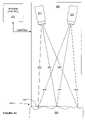
- FIG. 2illustrates a prior art solution to reduce the amount of time taken to scan an object.
- FIG. 2illustrates an image including lines 121 through 125 .
- By providing multiple linesit is possible to scan a greater surface area at once, thus allowing for more efficient processing of data associated with the object 100 .
- Limitations of using patterns such as are illustrated in FIG. 2include the need for a fixed reference point, and that the surface resolution capable of being mapped can be reduced because of the potential for improper processing of data due to overlapping of the discrete portions of the image.
- FIG. 3illustrates the shapes of FIGS. 1 and 2 from a side view such that only surface 102 is visible.
- the projection deviceprojects a pattern in a direction perpendicular to the surface 101 which forms the top edge of surface 102 in FIG. 3 .
- the point from the center of the projection lens to the surfaceis referred to as the projection axis, the rotational axis of the projection lens, or the centerline of the projection lens.
- an imaginary line from a center point of the viewing device(not shown) is refereed to as the view axis, the rotational axis of the view device, or the centerline of the view device, extends in the direction which the viewing device is oriented.
- the physical relationship of the projection axis and the view axis with respect to each otheris generally known.
- the projection axis and the view axisreside in a common plane.
- the relationship between the projection system and the view systemis physically calibrated, such that the relationship between the projector, and the view device is known.
- point of referenceis to describe the reference from which a third person, such as the reader, is viewing an image. For example, for FIG. 2 , the point of reference is above and to the side of the point that is formed by surfaces 101 , 102 , and 103 .
- FIG. 4illustrates the object 100 with the image of FIG. 2 projected upon it where the point of reference is equal to the projection angle.
- the point of referenceis equal to the projection angle
- no discontinuitiesappear in the projected image.
- the lines 121 – 125appear to be straight lines upon the object 100 .
- the point of referenceis equal to the projection axis
- no useful data for mapping objectsis obtained, because the lines appear to be undistorted.
- FIG. 5illustrates the object 100 from a point of reference equal to the view angle of FIG. 2 .
- the surfaces 104 , 103 and 101are visible because the view axis is substantially perpendicular to the line formed by surfaces 101 and 103 , and is to the right of the plane formed by surface 102 , see FIG. 2 , which is therefore not illustrated in FIG. 5 .
- the lines 121 and 122appear to be a single continuous straight line.
- line pairs 122 and 123 , and 123 and 124coincide to give the impression that they are single continuous lines.
- line 125is projected upon a single level surface elevation, surface 104 , line 125 is a continuous single line.
- the line pairs 121 and 122 , 122 and 123 , and 123 and 124will be improperly interpreted as single lines.
- the two-tiered object illustrated in FIG. 2may actually be mapped as a single level surface, or otherwise inaccurately displayed because the processing steps can not distinguish between the line pairs.
- FIG. 6illustrates a prior art solution for overcoming the problem described in FIG. 5 .
- FIG. 6illustrates the shape 100 having an image projected upon it whereby a plurality of lines having different line widths, or thickness, are used.
- FIG. 7illustrates the pattern of FIG. 6 from the same point of reference as that of FIG. 5 .
- line 421is still lined up with line 422 to form what appears to be a continuous line.
- line 421 and line 425have different thickness, it is now possible for an analysis of the image to determine the correct identity of the specific line segments.
- the analysis of the received imagecan now determine that line 422 projected on surface 104 , and line 422 projected on surface 101 are actually a common line. Utilizing this information, the analysis of the received image can determine that a step type feature occurs on the object being scanned, resulting in the incongruity between the two segments of line 422 .
- FIG. 8illustrates from a side point of reference a structure having a surface 710 with sharply varying features.
- the surface 710is illustrated to be substantially perpendicular to the point of reference of FIG. 8 .
- the object 700has side surfaces 713 and 715 , and top surfaces 711 and 712 . From the point of reference of FIG. 8 , the actual surfaces 711 , 712 , 713 and 715 are not viewed, only their edges are represented.
- the surface 711is a relatively steep sloped surface, while the surface 712 is a relatively gentle sloped surface.
- a first line 721has a width of four.
- a second projected line 722has a width of one.
- a third projected line 723has a width of eight.
- the line 721having a width of four, is projected onto a relatively flat surface 714 . Because of the angle between the projection axis and the view axis, the actual line 721 width viewed at the flat surface 714 is approximately two. If the lines 722 and 723 where also projected upon the relatively flat surface 714 their respected widths would vary by approximately the same proportion amount as that of 721 , such that the thickness can be detected during the analysis steps of mapping the surface. However, because line 722 is projected onto the angled surface 711 , the perspective from the viewing device along the viewing axis is such that the line 722 has a viewed width of two.
- Line 722appears to have a width of two because the steep angle of the surface 710 allows for a greater portion of the projected line 722 to be projected onto a greater area of the surface 711 . It is this greater area of the surface 722 that is viewed to give the perception that the projected line 722 has a thickness of two.
- line 723is affected by surface 712 to give the perception that the projected line 723 having an actual width of eight, has a width of two. This occurs because the angle of the surface 712 , relative to the viewing device allows the surface area with the projected line 723 to appear to have a width of two. The result of this phenomenon is further illustrated in FIG. 9 .
- FIG. 9illustrates the shape 700 of FIG. 8 from the point of reference of the view axis.
- the lines 721 – 723are projected onto the surface 714 in such a manner that the difference between the line thickness can be readily determined. Therefore, when an analysis of the surface area 714 occurs, the lines are readily discernable based upon the viewed image.
- the line 722can be erroneously identified as being line 721 because not only are the widths the same, but line 722 on surface 711 lines up with line 721 on surface 714 .
- the line 723having a projected width of eight, has a viewed width of two. Therefore, during the analysis of the received images, it may not be possible to distinguish between lines 721 , 722 , and 723 on surfaces 711 and 712 . The inability to distinguish between such lines can result in an erroneous analysis of the surfaces.
- One proposed method of scanningdisclosed in foreign patent DE 198 21 611.4, used a pattern that had rows of black and white triangles and squares running parallel to a plane of triangulation.
- the rowsused measuring features that include a digital encrypted pattern.
- a surface being scannedcauses shadowing and/or undercuts, a break in the sequence can result due to a portion of the pattern being hidden.
- the disclosed encrypted patternis such that breaks in the sequence can result in the inability to decode the pattern, since it may not be possible to know which portion of the pattern is missing.
- a further limitation of the type of encoding describedis that distortion can cause one encoding feature to look like another. For example, a triangle can be made to look like a square.
- FIG. 1illustrates an object being scanned by a single line in accordance with the prior art
- FIG. 2illustrates an object being scanned by a plurality of lines in accordance with the prior art
- FIG. 3illustrates a projection axis and a view axis associated with the lines of FIG. 2 in accordance with the prior art
- FIG. 4illustrates the object of FIG. 1 from a point of reference equal to the projection axis of FIG. 3 ;
- FIG. 5illustrates the object of FIG. 3 from the view axis of FIG. 3 ;
- FIG. 6illustrates an object having a plurality of lines of varying thickness projected upon it in accordance with the prior art
- FIG. 7illustrates the object of FIG. 6 from a point of reference equal to the view axis as shown in FIG. 3 ;
- FIG. 8illustrates an object from a side view having varying projected line thickness in accordance with the prior art
- FIG. 9illustrates the object of FIG. 8 from point of reference equal to the view axis of FIG. 8 ;
- FIG. 10illustrates a system in accordance with the present invention
- FIG. 11illustrates a portion of the system of FIG. 10 in accordance with the present invention
- FIG. 12illustrates, in flow diagram form, a method in accordance with the present invention
- FIG. 13illustrates, the object of FIG. 3 from a point of reference equal to the view axis of FIG. 3 in accordance with the present invention
- FIG. 14illustrates, the object of FIG. 3 from a point of reference equal to the view axis of FIG. 3 in accordance with the present invention
- FIG. 15illustrates an object having a pattern projected upon it in accordance with the present invention
- FIG. 16illustrates a table identifying various types of pattern components in accordance with the present invention
- FIG. 17illustrates a set of unique identifiers in accordance with the present invention
- FIG. 18illustrates a set of repeating identifiers in accordance with the present invention
- FIGS. 19–22illustrate, in flow diagram form, a method in accordance with the present invention
- FIG. 23illustrates a sequence of images to be projected upon an object in accordance with an embodiment of the present invention
- FIG. 24illustrates an image having varying features in accordance with an embodiment of the present invention
- FIG. 25illustrates a projected image feature being reflected off surfaces at different depths in accordance with the present invention
- FIG. 26illustrates the projected image of FIG. 25 as viewed at the different depths
- FIGS. 27–30illustrate a dentition object from various perspectives in accordance with the present invention
- FIG. 31illustrates a method in accordance with a specific embodiment of the present invention
- FIGS. 32 and 33illustrate a dentition object being scanned from various perspectives in accordance with the present invention
- FIG. 34illustrates primitive shapes for modeling a dentition object
- FIGS. 35 and 36illustrate methods in accordance with a specific embodiment of the present invention
- FIG. 37illustrates a graphical representation of a method for selecting various entry points for registration in accordance with the present invention.
- FIGS. 38–43illustrate methods in accordance with a specific embodiment of the present invention.
- an imageis projected upon a surface.
- the imagecan include a pattern having a plurality of individual shapes used to measure and map the surface.
- the plurality of individual shapesinclude features that are detectable in a direction parallel to the plane formed by a projection axis of the projected shapes and a point associated with a view axis.
- the imagefurther comprises a feature containing encoding information for identifying the plurality of shapes individually.
- the encoding featurevaries in a direction substantially orthogonal to a plane formed by the projection axis and a point of a view axis, and can be a separate feature from each of the plurality of individual shapes, can be a feature integral to the plurality of individual shapes, and/or be displayed at different time intervals from the plurality of individual shapes.
- the feature containing encoding informationis oriented such that the encoding information is retrieved along a line substantially perpendicular to a plane formed by the projection axis and the point along the view axis.
- the use of the featureis used to perform multi-frame reference independent scanning.
- FIGS. 10 and 11represent a system for implementing a specific embodiment of the present invention
- FIGS. 12 , and 19 – 22illustrate specific methods in accordance with the present invention
- FIGS. 13–18 , 23 , 24illustrates specific implementations of the method in combination with the system.
- FIG. 10illustrates a system controller 951 that provides control signals to the scanning device 980 .
- the scanning device 980projects an image bound by lines 962 and 963 , and retrieves, or views, the images within the reflected lines 972 and 973 .
- the system controller 951provides specific information to the scanner 980 specifying a specific image to be projected upon the surface 991 of the object 990 .
- the reflected imageis captured by the scanning device 980 , which in turn provides the captured information back to the system controller 951 .
- the captured informationcan be provided back to system controller 951 automatically, or can be stored within the scanning device 980 and retrieved by the system 951 .
- the image data once received by the system controller 951is analyzed in order to determine the shape of the surface 991 . Note that the analysis of the received data can be performed either by the system controller 951 , or by an external-processing device that is not shown.
- the scanning device 980which includes a projecting device (projector) 960 and a viewing device (viewer) 970 .
- the projector 960is oriented such that the image is projected on the object 990 .
- the projector 960has a projection axis 961 .
- the projection axis 961begins at the center of the lens projecting the image and is representative of the direction of projection.
- the viewer 970has a view axis 971 that extends from the center of the lens associated with the viewer 970 and represents the direction from which images are being received.
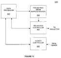
- FIG. 11illustrates in greater detail the system controller 951 of FIG. 10 .
- the system controller 951further includes data processor 952 , a projection image representation 953 , the projector controller 954 , and a viewer controller 955 .
- the viewer controller 955provides the interface needed to receive data from the viewer 970 representing the reflected image data.
- the reflected image datais received from the viewer 970 at the viewer controller 955 , and subsequently provided to the data processor 952 .
- the projector controller 954provides the interface necessary to control the projector 960 .
- the projector controller 954provides the projector 960 with the image to be projected in a format supported by the projector.
- the projector 960projects the image onto the surface of the object.
- the projector controller 954receives or accesses the projection image representation 953 in order to provide the projector with the image.
- the projection image representation 953is an electronic representation of the image stored in a memory location.
- the stored imagecan represent a bit mapped image, or other standard or custom protocol used to define the image to be projected by the projector 960 .
- the projection imageis a digital image (electrically generated)
- the representationcan be stored in memory by data processor 952 , thereby allowing the data processor 952 to modify the projection image representation, it is possible to vary the image as necessary in accordance with the present invention.
- the projection image representation 953need not be present. Instead, the projection controller 954 may select one or more transparencies (not illustrated) associated with the projector 960 . Such transparencies can include any combination of films, plates, or other types of retical devices that project images.
- the data processor 952controls the projection and reception of data through the controller 954 and 955 respectively.
- FIG. 12illustrates a method in accordance with the present invention that will be discussed with reference to the system of FIG. 10 and the accompanying Figures.
- projection/view planerefers to a plane formed by the projection axis and at least one point of the view axis.
- the term projection/view planeis best understood with reference to FIG. 3 . Assuming that FIG. 3 represents a cross section of the object 100 .
- the projection axis illustratedis directed such that it lies entirely within the plane formed by the sheet of paper including FIG. 3 .
- the view axis of FIG. 3is also lying entirely within the plane represented by the sheet of paper of FIG. 3 .
- the projection/view plane formed by the projection axis of FIG. 3 and at least one point of the view axis of FIG. 3includes the sheet of paper on which the Figure is drawn.
- the projection/view planecan be described to contain substantially all of the projection axis and at least one point of the view axis, or all of the view axis and at least one point of the projection axis.
- the point of the view axis nearest the view deviceis the point to be included within that projection/view plane.
- the projection/view plane described with reference to FIG. 3would be substantially orthogonal to the surface 104 , and orthogonal to each of the lines 121 – 125 .
- the projection/view planeis represented by line 99 , which represents the plane from an edge view intersecting the lines 121 – 125 .
- an imageis projected having an encoding (variable) feature with a component, or components, that varies orthogonal to the projection/view plane.
- the projection/view planeis illustrated by the line 936 indicating that the orientation of the view/projection plane is on edge such the plane appears to be a line, and each of the shapes or patterns 931 – 935 represent an encoding feature.
- Each of the individual features 931 – 935has a component(s) that varies in a direction orthogonal to the projection/view plane.
- feature 933varies orthogonal to the projection plane such that three individual lines can be identified.
- the thicknesses of the three individual linesBy varying the thicknesses of the three individual lines a unique pattern is associated with each of the features 931 – 935 .
- the bar code feature 933varies orthogonal between no line, thin line, no line, thick line, no line, thin line, and no line.
- the individual lines of the feature 933are projected parallel to the projection/view plane. Projecting lines parallel to the projection/view plane reduces, or eliminates, the viewed distortion affects of surface topology on the width of the lines.
- the thickness, or relative thickness, of each individual line of the feature 933can be readily identified independent of surface topology. As a result, the feature 933 can be identified substantially independent of surface topology.
- FIG. 13displays a specific embodiment of an image having five separate lines (measuring features) 431 – 435 .
- the lines 431 – 435 illustratedhave lengths that run substantially orthogonal to the projection/view plane, and are uniformly spaced from each other in a direction parallel to the projection/view plane. By providing a plurality of lines which are detectable in the direction parallel to the projection/view plane, multiple measuring lines can be viewed and analyzed simultaneously.
- five unique bar codes 931 – 935are also illustrated.
- Each of the unique bar codes (variable features) 931 – 935are associated with, and repeated along a respective measuring feature 431 – 435 . In other implementations, each bar code can be repeated along a measuring feature more than the two times illustrated. Note that the bar codes illustrated are illustrated as repeating sets. In other implementations, the bar codes would not need to be grouped in sets.
- the lines 431 – 435 and bar codes 931 – 935are generated using visible light that is low-intensity, such that the pattern is eye-tolerant and skin tolerant.
- the lines 431 – 435can be viewed as white lines, and the bar codes 931 – 935 can be viewed as specific colors or combinations of colors.
- high-intensity or laser lightcan also be used depending upon the application.
- the lines 432 and 433appear to be a continuous line at the edge of object 101 .
- the lines 432 and 433can be distinguished from each other by analyzing the (encoding feature) barcodes associated with each line. In other words, where line 432 and line 433 appear to the viewer to be a common line, it can now be readily determined that they are two different lines because the bar code associated with line 432 on the left would not be the same as the bar code associated with line 433 on the right.
- the analysis of the retrieved imageswould determine that there is a discontinuity somewhere between the left most bar code 932 and the right most bar code 933 causing the line segments 432 and 433 to appear as a common line.
- the location of such an edgecan be determined with greater precision by providing repeating bar code patterns in relatively close proximity to one another. For example, the edge where surface 102 meets surface 101 can be determined only to an accuracy equal to the spacing between adjacent bar codes. This is because when the analysis encounters what appears to be a single line having two different bar codes it is unknown where between the two bar codes the discontinuity has occurred. Therefore, by repeating the bar code more frequently along the measuring lines of FIG. 13 the location of discontinuities can be more accurately identified.
- the encoding features 931 – 935 of FIG. 13are non-repeating in that no two bar codes are the same. However, an encoding value, or sequence, can be repeated within a projected image as long as ambiguity is avoided. For example, if the image includes 60 lines (measuring features) using a binary encoding, 6 bits of data are needed to identify each line uniquely. However, due to the fact that the range of focus of the scanner is limited by the depth of field, each individual line of the 60 lines can show up as a recognizable image only within a certain range.
- FIGS. 25 and 26better illustrate how the depth of field affects the repeating of features.
- FIG. 25illustrates a projector projecting a SHAPE along a path 2540 .
- the SHAPEWhen the SHAPE is projected onto a surface its image is reflected along a reflection path to a viewing device 2506 .
- reflection path 2544results when the SHAPE is reflected off a surface at the location 2531
- a reflection path 2541results when the SHAPE is reflected off a surface at the location 2532
- a reflection path 2542results when the SHAPE is reflected off a surface at the location 2533
- a reflection path 2543results when the SHAPE is reflected off a surface at the location 2534 .
- FIG. 26represents the SHAPE as the viewer 2506 would view it.
- the image reflected off of the surface 2531which is the surface closest to the projector, is viewed as the right most image in FIG. 26
- the image reflected off of the surface 2534which is the surface furthest from the projector, is viewed as the left most image in FIG. 26 .
- the left and right most imageswhich are furthest and closest to the projector 2505 respectively, are out of focus. Because they are out of focus they can not be accurately detected based upon the image received by the viewing device 2506 .
- any surface closer to the projection device 2505 than plane 2525 , or further from the projection device 2505 than the plane 2526is not capable of reflecting a usable SHAPE because it is outside the viewable range 2610 , or field of view. Therefore, the SHAPE can be repeated and still be uniquely identified, so long as the repeated SHAPE can not be viewed within the range 2610 of FIG. 6 .
- a projectorprojects approximately 80 lines.
- Each of the 80 lineshas a color-coded encoding sequence. For example, if three colors are used (red, blue, green), an encoding feature having three color locations could uniquely identify 27 different lines.
- This coding sequence of 27 linescan be repeated three times to cover all 80 lines, provided the field of view is such that lines having the same encoding can not be viewed at the same location.
- five color locationscan be added with or without increasing the number of lines in a sequence to provide recognition capability where a specific color location may be lost.
- coding featuresmay be repeated, as long as the fields of view in which each of the repeating features may be viewed do not overlap.
- a sequence of 12 unique encoding featuresrequiring only four bits of binary data, can be repeated five times to encode all 60 lines, provided there is no chance for features to be viewed at the same location.
- reference independent scanningBy providing a pattern having a large number of measuring features with associated coding features reference independent scanning is achieved. Specifically, neither the object nor the scanner need to be fixed in space, nor with reference to each other. Instead, on a frame by frame basis, the reference independent scanner retrieves enough measuring information (a 3D cloud), which is accurate due to the encoding feature, to permit registration to its adjacent frame. Registration is the processes which determines the overlapping features on adjacent frames to form an integrated map of the object.
- FIG. 14illustrates the object of FIG. 13 whereby the measuring lines 431 – 435 have varying thickness. However, the thickness of lines 431 – 435 is subject to distortion. Thereby making identification of the individual lines 431 – 435 based upon their thickness alone prone to error. This is better illustrated with reference to FIG. 15 .
- FIG. 15represents the object 700 of FIGS. 8 and 9 having a pattern in accordance with the present invention projected upon its surface.
- FIG. 15illustrates the projection of lines 721 – 723 having varying widths.
- the lines 722 and 723when projected onto the surfaces 711 and 712 respectively, appear to have the same line thickness as line 721 . Therefore, merely having measuring lines of varying thickness will not allow an analysis of the images to determine which line is which.
- identification of the lines 721 – 723 , and the subsequent mapping analysisis improved over the prior art.
- FIG. 16a table is illustrated where a specific set of shapes used in a direction orthogonal to the projection/view plane are illustrated.
- Column 1 of table 16represents unique feature identifiers.
- the columns 2 – 4 of table 16illustrate specific manners in which each feature identifier can be represented.
- Column 2indicates bar codes.
- Column 3indicates colors capable of being used either alone or with other encoding features. Note that some types of encoding features, including color features, can be implemented as an integral part of a measuring feature as well as an encoding feature separate from the measuring feature. Likewise, other types of encoding can be based upon the intensity at which a measuring feature and/or its encoding feature is projected.
- Column 4represents patterns that can be utilized either independently from the shape to identify the shape, or in combination as part of a shape.
- a line comprising a repeating pattern sequence of the type illustrated in Column 4can be provided.
- the change of pattern in a direction orthogonal to the projection/view planecan be relative to the actual shape itself.
- one of ordinary skill in the artwill recognize that many variations as to variable components would be anticipated by the sent invention.
- FIG. 17illustrates in tabular form, the use of unique non-repeating identifiers for each line. For example, referring to the first row of FIG. 17 the sequence 0 -F sequentially is presented. In one implementation, each of the values from 0 through F will represent a unique code associated with a specific line. One skilled in the art will recognize that in order to identify the specific codes, some type of spacer may need to exist between each individual code. For example, a long space, or a unique code can be used.
- FIG. 18illustrates four unique repeating code sequences.
- the letter S in table 18is utilized to represent a spacer used between repeating sequences.
- a spacercan be some unique identifier specifying where each of the repeating codes of the encoding sequence begins and/or ends.
- a representation of the surface imageis received at a viewer. This is analogous to the discussion of FIG. 10 whereby the viewer 970 receives the reflected image.
- the location of a point associated with an objectis determined based upon the orthogonally varying feature.
- the pointis based upon the variable component because each one of the shapes, e.g. lines is qualified to a unique code pattern prior to being used for object analysis.
- FIG. 19illustrates sub steps to be associated with step 611 of FIG. 12 .
- a first imageis projected, while at step 622 a second feature is projected.
- the first imagecan be analogous to the combination of the measuring line 431 and its associated encoding features 931 .
- the second featurecould be represented by the combination of the measuring line 432 and its encoding features 932 .
- a specific line in a group of linessuch as illustrated in FIG.
- steps 621 and 622can occur at different times as discussed with reference to FIG. 23 .
- FIG. 21illustrates another method in accordance with the present invention.
- a plurality of first features, and a plurality of second featuresare projected. These features may be projected simultaneously, or at separate locations.
- one of the plurality of first featuresis determined, or identified, based upon the second features.
- the plurality of first featureswould include the lines measuring 431 – 435 .
- the bar code 931 – 935a specific one of the lines 431 – 435 can be identified.
- the location of a point at the surfaceis determined based upon the specific one of the plurality of parallel first features.
- This specific embodimentis an advantage over the prior art, in that a line identified by the analysis of the received shape is not utilized until its identity is verified based upon the encoding information.
- FIG. 22illustrates another method in accordance with the present invention.
- parallel first and second discrete shapesare projected. Examples of such discrete shapes would include the lines 431 and 432 of FIG. 14 . However, one of ordinary skill in the art will recognize that a variety of other parallel shapes could be projected.
- an encoding feature relative to the first discrete shapeis projected.
- the encoding feature relative to the line 432could include the encoding feature 932 or even an encoding feature 933 .
- an encoding feature relative to the second discrete shapeis projected.
- the first discrete shapeis identified based upon the first encoding feature. This is accomplished in a manner similar to as discussed previously.
- a location of a specific point of an objectis determined based upon the first discrete shape.
- FIG. 23illustrates another embodiment of the present invention. Specifically, FIG. 23 illustrates a series of images projected at times T 1 , T 2 , T 3 and T 4 .
- the image projectedincludes measuring features 1011 through 1013 .
- no encoding featureis projected.
- an image containing encoding features 1021 – 1023is projected.
- the patterns of times T 1 and T 2are repeated during times T 3 and T 4 respectively.
- the result of alternating the projection of encoding and measuring featuresis that denser patterns can be used, allowing for more information to be obtained.
- the image of time T 4shows the encoding features 1021 – 1023 overlying the measuring features 1011 – 1013 .
- the measuring featureshave been included for illustration purposes only, and would not generally be present at the same time as the encoding features.
- FIG. 24illustrates an image having features with different characteristics. Specifically, FIG. 24 illustrates an image 1100 having lines 1131 through 1134 with a distance X between the individual lines, while the distance between lines 1134 , 1135 , and 1136 have a substantially greater distance Y separating the lines.
- the line 1135can be used to map surface features that otherwise may not be mappable. Note that the pattern 1100 could be used with or without the coding techniques described herein.
- each 2D point of the 2D image framecan be converted into a 3D point using conventional 3D imaging techniques, provided each 2D point of the 2D image frame can be correlated to a projected point.
- the use of a projected frame pattern that has encoding featuresenables correlation of the points of the 2D image to a respective projected point.
- Multi-frame reference independent scanningis described herein in accordance with another aspect of the present disclosure.
- multiple 3D image framesare received by using a hand-held scanner to scan an object one frame at a time to obtain a plurality of frames, where each frame captures only a portion of the object.
- reference independent scanninghas a spatial position that is frame-by-frame variable relative to the object being scanned, and whose spatial position is not fixed, or tracked, relative to a reference point. For example, there is no fixed reference point relative to the object being scanned.
- One type of reference independent scanner disclosed hereinincludes a hand-held scanner that projects a pattern in successive frames having measuring features and encoding features. This allows each viewed point of a frame to have a known corresponding projected point, thereby enabling the 2D frame data to be converted into 3D frame data.
- FIGS. 27–28are used to discuss multiple frame reference independent scanning.
- FIGS. 27 , 28 , and 30illustrate an object 2700 from different points of view.
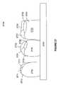
- the object 2700includes three teeth 2710 , 2720 , and 2730 , and a gum portion 2740 that is adjacent to the three teeth.
- the FIG. 27 point-of-viewis such that a plurality of non continuous surface portions are viewed.
- three noncontiguous surface portions 2711 – 2713are viewed.
- the surface portion 2713represents a side portion of the tooth 2710 .
- the surface portion 2711represents a portion of the tooth 2710 biting surface that is not continuous with surface portion 2713 .
- the surface portion 2712represents another portion of the tooth 2710 biting surface that is not continuous with either portion 2711 or 2713 .
- tooth 2720has four surface portions 2721 – 2724
- tooth 2730has four surface portions 2731 – 2734 .
- FIG. 28illustrates the object 2700 from a slightly different point-of-view ( FIG. 28 point-of-view).
- the point-of-view change from FIG. 27 to FIG. 28is the result of the viewer, i.e. scanner, moving in a direction that allows a greater portion of the upper teeth surfaces to be viewed.
- the change in point-of-viewhas resulted in variations to a plurality of viewed surface portions.
- tooth 2710tooth portion 2813 now represents a smaller 2D surface than did its corresponding tooth portion 2713 ; while tooth portions 2811 and 2812 now are viewed as larger 2D surfaces than their corresponding portions 2711 and 2712 of FIG. 27 .
- tooth 2720surface 2824 now is viewed as a smaller 2D surface than its corresponding tooth surface 2724 of FIG. 27 .
- tooth surface 2821represents a continuously viewed tooth surface that includes both of the surfaces 2721 and 2723 from the FIG. 27 point-of-view.
- the viewed 2D surfaces 2832 and 2835each include portions of surface 2732 and previously unviewed surface area.
- FIG. 29is from the same point-of-view as FIG. 28 with the viewed surface portions of FIG. 27 indicated as shaded areas.
- surface portion 2711 of FIG. 27is represented as a shaded portion within the surface portion 2811 .
- the change in the point-of-view between FIG. 27 and FIG. 28results in a viewed surface portion 2811 that encompasses the smaller viewed surface portion 2711 .
- the change in perspectivehas resulted in different surface portions being viewed.
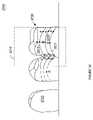
- FIG. 30illustrates the object 2700 from another point-of-view. Specifically, the FIG. 30 point-of-view is from directly over the teeth 2710 – 2730 . Superimposed onto FIG. 30 are the viewed surface portions of FIG. 28 .
- the object 2700 illustrated in FIGS. 27–30will be referenced further herein to describe a specific embodiment of multiframe reference independent scanning.
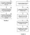
- FIG. 31illustrates a method 3100 in accordance with a specific embodiment of reference independent scanning.
- the objectis scanned to obtain a 2D cloud of data.
- the 2D cloud of dataincludes a plurality of frames. Each of the frames has a plurality of 2D points, which, if viewed, would represent a 2D image.
- a first frame of the 2D cloud of datais converted to 3D frame model.
- a 3D frame modelis a 3D point model, which includes a plurality of points in three-dimensional space.
- the actual conversion to a 3D frame point modelis performed on some or all of the frame's 2D cloud of data using conventional techniques for converting a scanned 2D cloud of data into a 3D point model.
- surfaces with non continuous viewed surfacessuch as the teeth 2710 – 2730 of FIG. 27 , can be successfully scanned frame-by-frame.
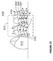
- FIGS. 32 and 33further illustrate the object 2700 being scanned from the FIG. 27 and FIG. 28 points-of-view respectively.
- the scan patternincludes scan lines 3221 – 3223 . Any scan line portion outside the frame boundary 3210 is not capable of being properly scanned.
- each scan linewhen sensed at the CCD (charge coupled diode) chip of the scanner, is converted to plurality of 2D points (cloud of data).
- Some or all points of a scan linecan be used in accordance with the present invention. For example, every other, or every third point of a scan line can be used depending upon the desired resolution of a final 3D model.
- FIG. 32illustrates four points (A–D) of each line being identified. A 2D coordinate value, such as an X-Y coordinate, is determined for each of these points.
- a scan rate of 1 to 20 frames per secondis used. Greater scan rates can be used. In a specific embodiment, the scan rate is chosen to allow for real-time viewing of a three-dimensional image.
- the pulse time during which each frame is capturedis a function of the speed at which the scanner is expected to be moving. For dentition structures, a maximum pulse width has been determined to be approximately 140 micro-second, although much faster pulse widths, i.e. 3 micro-seconds, are likely to be used.
- the teeth 2710 – 2730will be coated with a substance that results in a surface that is more opaque than the teeth themselves.
- each point of the cloud of datawill be analyzed during the various steps and functions described herein.
- only a portion of the cloud of datawill be analyzed. For example, it may be determined only every 3 rd or 4 th point needs to be analyzed for a desired resolution to be met.
- a portion of the frame datacan be a bounding box that is smaller than the entire frame of data such that only a specific spatial portion of the cloud of data is used for example, only a center portion of the cloud of data is included within the bounding box.
- FIG. 33illustrates the object 2700 being scanned from the FIG. 28 point of view.
- the viewed pattern including lines 3321 – 3323are positioned differently on the teeth 2710 – 2730 .
- the frame boundary 3310has moved to include most of the tooth 2720 .
- FIG. 34illustrates another embodiment of a 3D frame model referred to herein as a 3D primitive model.
- a 3D primitive modelincludes a plurality of primitive shapes based upon the frame's 3D points. In the specific embodiment illustrated adjacent points from the 3D point model are selected to form triangles, including triangle PS 1 –PS 3 as primitive shapes. Other implementations can use different or varied primitive shapes.
- a second 3D frame modelis generated from the second frame of the cloud data.
- the second 3D frame modelmay be a point model or a primitive model.
- a registrationis performed between the first frame model and the second frame model to generate a cumulative model.
- “Registration”refers to the process of aligning the first model to the second model to determine a best fit by using those portions of the second model which overlap the first model. Those portions of the second model that do not overlap the first model are portions of the scanned object not yet mapped, and are added to the first model to create a cumulative model. Registration is better understood with reference to the method of FIG. 35 .
- FIG. 35includes a registration method 3500 that, in a specific embodiment, would be called by one of the registration steps of FIG. 31 .
- a registration method 3500that, in a specific embodiment, would be called by one of the registration steps of FIG. 31 .
- an entry point into registrationis determined.
- the entry point into registrationdefines an initial guess of the alignment of the overlapping portions of the two models. The specific embodiment of choosing an entry point will be discussed in greater detail with reference to FIG. 36 .
- a registration of the two shapesis attempted. If an overlap is detected meeting a defined closeness of fit, or quality, the registration is successful. When the registration is successful the flow returns to the calling step of FIG. 31 . When a registration is not successful the flow proceeds to the step 3598 were a decision whether to continue is made.
- a decision to continuecan be made based on a number of factors. In one embodiment, the decision to continue is made based upon the number of registration entry points that have been tried. If the decision at step 3598 is quit registration attempts, the flow proceeds to step 3503 where registration error handling occurs. Otherwise the flow continues at step 3501 .
- FIG. 36illustrates a specific method for choosing a registration entry point.
- a determinationis made whether this is the first entry point for a specific registration attempt of a new frame. If so the flow proceeds to step 3601 , otherwise the flow proceeds to step 3698 .
- the X and Y components of the entry pointare determined based upon two-dimensional analysis of the 2D cloud of data for each of the two frames.
- the two-dimensional analysisperforms a cross-correlation of the 2D images. These 2D images do not have to be from the 2D cloud of data, instead, data associated with a plain video image of the object, with no pattern, can be used for cross correlation. In this way, a probable movement of the scanner can be determined.
- the cross-correlationis used to determine how the pixels have moved to determine how the scanner has probably been moved.
- a probable movement in the Z directionis determined.
- the previous frame's Z-coordinateis used, and any change in the Z-direction is calculated as part of the registration.
- a probable Z coordinateis calculated as part of the entry point.
- the optical parameters of the systemcan “zoom” the second frame in relationship to the first one until the best fit is received. The zoom factor that is used for that could tell us how far the two surfaces are away from each other in Z.
- the X, Y and Z coordinatescan be aligned so that the Z-coordinate is roughly parallel to the view axis.
- step 3606the entry point value is returned.
- step 3698a determination is made whether all entry point variations have been tried for the registration steps 3601 and 3602 . If not the flow proceeds to step 3603 , otherwise the flow proceeds to step 3697 .
- FIG. 37illustrates a specific method for selecting the registration entry point variations. Specifically, FIG. 37 illustrates the initial entry point E 1 and subsequent entry points E 2 –E 9 . The entry points E 2 –E 9 are selected sequentially in any predetermined order.
- the specific embodiment of FIG. 37illustrates the registration entry points E 2 –E 9 as various points of a circle 3720 having a radius 3710 .
- the dimensions of the entry point variationsare two-dimensional, for example the X and Y dimensions. In other embodiments, the entry points can vary in three dimensions. Note that varying number of entry points, i.e. subsets of entry points, can be used to speed up the registration process. For example, single frame registration as used herein could use fewer than the nine entry points indicated. Likewise, cumulative registration, described herein, could benefit by using more than the nine points illustrated.
- step 3697the flow proceeds to step 3697 once all variations of the first identified entry point have been tried.
- step 3697all entry points associated with the first identified entry point have been tried, and it is determined whether a second identified entry point has been identified by step 3604 . If not, flow proceeds to step 3604 where the second entry point is defined.
- the scanner movement between two previous frame modelsis determined.
- an assumptionis made that the scanner movement is constant for at least one additional frame.
- the entry point at step 3604is defined to be the location of the previous frame plus the calculated scanner movement.
- step 3606returns the entry point to the calling step of FIG. 35 .
- an assumptioncan be made that the direction of the scanner movement remained the same but that it accelerated at a difference rate.
- step 3696a determination is made whether an additional registration entry point variation for the second identified entry point exists. If so, the flow proceeds to step 3605 , otherwise the flow returns to the calling step of FIG. 35 at step 3607 and indicates that selection of a new entry point was unsuccessful. At step 3605 the next entry point variation of the second identified entry point is identified and the flow returns to the calling step of FIG. 35 .
- Different entry point routinescan be used depending upon the type of registration being performed. For example, for a registration process that is not tolerant of breaks in frame data, it will be necessary to try more entry points before discarding a specific frame. For a registration process that is tolerant of breaks in frame data, simpler or fewer entry points can be attempted, thereby speeding up the registration process.
- next 3D model portionis generated from the next frame's cloud of data.
- step 3106registration is performed between the next 3D model portion and the cumulative model to update the cumulative model.
- the cumulative modelis updated by adding all the new points from frame to the existing cumulative model to arrive at a new cumulative model.
- a new surfacecan be stored that is based on the 3D points acquired so far, thereby reducing the amount of data stored.
- the method 3100is completed, otherwise the flow proceeds to steps 3105 through step 3199 , until each frame's cloud of points has been registered.
- a model for the object 2700from a plurality of smaller frames, such as frames 3210 and 3310 .
- highly accurate models of large objectscan be obtained. For example, a model of a patients entire dentition structure, including gums, teeth, and orthodontic and prosthetic structures can be obtained. In another embodiment, a model of the patients face can be obtained.
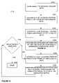
- FIG. 38illustrates a method 3800 , which is an alternate method of registering an object using a plurality of frames from a reference independent scanner. Specifically, at step 3801 the object is scanned to receive a cloud data for the object. As previously described, the cloud of data includes data from a plurality of frames, with each frame including a plurality of points.
- a single frame registrationis performed.
- a single frame registrationperforms a registration between adjacent frames of the scanned image without generating a cumulative model.
- a cumulative image of the single frame registration processis displayed.
- the image formed by the single frame registration processcan be used to assist in the scanning process.
- the image displayed as a result of the single frame registrationwhile not as accurate as a cumulative model, can be used by the scanner's operator to determine areas where additional scanning is needed.
- the single frame registration processis such that any error introduced between any two frames is “extended” to all subsequent frames of a 3D model generated using single frame registration.
- the level of accuracyis adequate to assist an operator during the scanning process.
- the registration resultswhich describe the movement from one frame to another, can be used as an entry point for the cumulative registration process.
- Single frame registrationis discussed in greater detail with reference to FIG. 39 .
- a cumulative registrationis performed.
- the cumulative registrationcreates a cumulative 3D model by registering each new frame into the cumulative model. For example, if 1000 individual frames were captured at step 3801 representing 1000 reference independent 3D model portions (frames), the cumulative registration step 3803 would combine the 1000 reference independent 3D model portions into a single cumulative 3D model representing the object. For example, where each of the 1000 reference independent 3D model portions represent a portion of one or more teeth, including frames 3210 and 3310 of FIGS. 32 and 33 , the single cumulative 3D model will represent an entire set of teeth including teeth 2710 – 2730 .
- step 3804the results of the registration are reported. This will be discussed in further detail below.
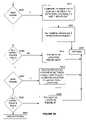
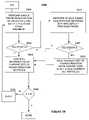
- FIG. 39describes a method 3900 that is specific to a single frame rendering implementation for step 3802 of FIG. 38 .
- a variable xis set equal to 2.
- a registration between the current frame (3DFx) and the immediately, or first, previous adjacent frame (3DFx-1)is performed. Registration between two frames is referred to as single frame registration. A specific embodiment of registration between two models is discussed in greater detail with reference to the method illustrated in FIG. 40 .
- step 3999it is determined whether or not the single frame registration of step 3904 was successful.
- a registration methodsuch as the method of FIG. 40 , provides a success indicator which is evaluated at step 3999 .
- the flowproceeds to step 3905 when registration is successful, otherwise the flow proceeds to step 3907 .
- step 3905the current 3D frame (3DFx) is added to the current frame set of 3D frames.
- this setwill generally be a set of transformation matrices.
- the current frame set of 3D framesis a sequential set of frames, where each frame in the sequence has a high degree of likelihood being successfully registered with [both] of its two adjacent frames.
- the newly registered framecan be displayed relative to the previous frame that is already being displayed.
- step 3907if the registration of step 3904 was not successful.
- step 3907a registration is attempted between current frame (3DFx) and the second previously adjacent frame (3DFx-2).
- Step 3997directs the flow to step 3905 if the registration of step 3907 was successful. Otherwise, step 3997 directs the flow to step 3908 , thereby indicating an unsuccessful registration of the current frame (3DFx).
- step 3908saves the current frame set, i.e. set of matrices, and a new current frame set is begun. Flow from step 3908 proceeds to step 3905 where the current frame is added to the current frame set, which was newly created at step 3908 . Therefore, it is possible for the single frame registration step 3802 to identify multiple frames sets.
- breaks in single frame registrationare generally acceptable because the purpose of single frame registration is to assist the operator and define entry points to cumulative registration.
- One method of dealing with breaks during single frame registrationis to merely display the first frame after the break at the same location as the last frame before the break, thereby allowing the operator to continue to view an image.
- a first modelis a 3D primitive shape model, while the second model is a 3D point model.
- the primitive shapes in the first 3D modelare referenced as S 1 . . . Sn, where n is the total number of shapes in the first model; and, the points in the second 3D model are references as P 1 . . . Pz, where z is the total number of points in the second model.
- each individual point of the second model P 1 . . . Pzis analyzed to determine a shape closest to its location.
- the shape S 1 –Sn that is the closest to P 1is the shape having the surface location that is the closest to P 1 than any other surface location of any other shapes.
- the shape closest to point P 1is referred to as Sc 1
- the shape closest to point Pzis referred to as Scz.
- points that are located directly above or below a triangleare associated to a triangle, and points that are not located directly above or below a triangle surface are associated to a line formed between two triangles, or a point formed by multiple triangles. Note that in the broad sense that the lines that form the triangles and the points forming the corner points of the triangles can be regarded as shapes.
- vectors D 1 . . . Dzare calculated for each of the points P 1 . . . Pz.
- each vectorfor example D 1
- the non-overlapping pointswhich are not needed for registration, have an associated vector having a comparatively large magnitude than an overlapping point, or may not reside directly above or below a specific triangle. Therefore, in a specific embodiment, only those vectors having a magnitude less than a predefined value (an epsilon value) are used for further registration.
- epsilon valuescan also be used to further reduce risks of decoding errors. For example, if one of the measuring lines of the pattern is misinterpreted to be a different line, the misinterpretation can result in a large error in the Z-direction. For a typical distance between adjacent pattern lines of approximately 0.3 mm and an angle of triangulation of approx. 13°; an error in the X-direction of 0.3 mm results in a three-dimensional transformation error of approx. 1.3 mm (0.3 mm/tan 13°) in the Z-direction.
- the epsilon valueis first selected to be a value greater than 0.5 mm, such as 2.0 mm, and after reaching a certain quality the value is reduced.
- the vectors D 1 . . . Dzare treated as spring forces to determine movement of the second 3D model frame.
- the second 3D modelis moved in a linear direction defined by the sum of all force vectors D 1 . . . Dz divided by the number of vectors.
- the vectors D 1 . . . Dzare recalculated for each point of the second 3D model.
- the vectors D 1 . . . Dzare treated as spring forces to determine movement of the second 3D model.
- the second 3D model frameis rotated about its center of mass based upon the vectors D 1 . . . Dz.
- the second 3D modelis rotated about its center of mass until the spring forces are minimized.
- the quality of the registrationis determined with respect to the current orientation of the second 3D model.
- various methodscan be used to define the quality of the registration. For example, a standard deviation of the vectors D 1 . . . Dz having a magnitude less than epsilon can be used.
- qualityis calculated using the following steps: square the distance of the vectors, sum the squared distances of all vectors within the epsilon distance, divide this sum by the number of vectors, and take the square root.
- the vector values D 1 . . . Dzneed to be recalculated after the rotation step 4006 .
- step 4098It is determined at step 4098 whether the current quality of registration is improving. In a specific embodiment, this is determined by comparing the quality of the previous pass through the loop including step 4003 with the current quality. If the quality is not improving the flow returns to the calling step with an indication that the registration was not successful. Otherwise, the flow proceeds to step 4003 .
- step 4003Upon returning to step 4003 , another registration iteration occurs, using the new frame location. Note that once the frame data has been scanned and stored there is no need to do the registration exactly in the order of scanning. Registration could start other way round, or use any other order that could make sense. Especially when scanning results in multiple passes there is already a knowledge of where a frame roughly belongs. Therefore, the registration of adjacent frames can be done independently of the order of imaging.
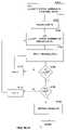
- FIG. 41illustrates a specific embodiment of a method 4100 for FIG. 38 .
- the method 4100discloses a cumulative registration which attempts to combine all of the individual 3D frame models into a single cumulative 3D model.
- Steps 4101 – 4103are setup steps.
- a variable xis to set equal to 1
- a variable x_lastdefines the total number of 3D model sets. Note, the number of 3D model sets is based upon the step 3908 of FIG. 39 .
- a 3D cumulative model (3Dc)is initially defined to equal the first 3D frame of the current set of frames.
- the 3D cumulative modelis modified to include that information from subsequent frame models that is not already represented by the 3D cumulative model.
- Yis set equal to 2
- a variable Y_lastis defined to indicate the total number of frames (3DF), or frame models, in the set Sx, where Sx represents the current set of frame models being registered.
- the 3D cumulative model (3Dc)is modified to include additional information based upon the registration between the current 3D frame model being registered (Sx(3DFy)) and the 3D cumulative model (3DC).
- Sx(3DFy)the current 3D frame model
- 3Dyindicates the frame model
- Sxindicates the frame set.
- a specific embodiment for performing the registration of step 4104is further described by the method illustrated in FIGS. 42–43 .
- step 4199it is determined whether the current 3D frame model is the last 3D frame model of the current step. In accordance with a specific implementation of FIG. 41 , this can be accomplished by determining if the variable Y is equal to the value Y_last. When Y is equal to Y_last the flow proceeds to step 4198 . Otherwise, the flow proceeds to step 4106 , where Y is incremented, prior to returning to step 4104 for further registration of 3D frame models associated with current set Sy.
- step 4198it is determined whether the current set of frames is the last set of frames. In accordance with the specific implementation of FIG. 41 , this can be accomplished by determining if the variable x is equal to the value x_last. The flow proceeds to step 4105 when x is equal to a x_last. Otherwise, the flow proceeds to step 4107 , where x is incremented, prior to returning to step 4103 for further registration using the next set.
- Step 4105reports results of the registration of the method 4100 , as well as any other cleanup operations. For example, while ideally the method 4100 results in a single 3D cumulative model in reality multiple 3D cumulative models can be generated (see discussion at step 4207 of FIG. 43 ). When this occurs step 4105 can report the resulting number of 3D cumulative models to the user, or to a subsequent routine for handling. As a part of step 4105 , the user can have an option to assist in registering the multiple 3D models to each other. For example, if two 3D cumulative models are generated, the user can manipulate the 3D cumulative models graphically to assist identification of entry point, which can be used for performing a registration between the two 3D cumulative models.
- a second cumulative registration processcan be performed using the resulting matrices from the first cumulative registration as entry points for the new calculations.
- an enlarged number of entry pointscan be used, or a higher percentage of points can be used.
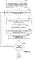
- FIGS. 42–43illustrate a specific embodiment of registration associated with step 4104 of FIG. 41 .
- Step 4201is similar to step 4002 of FIG. 40 , where each point (P 1 . . . Pm) of the current frame Sx(3Dy) is analyzed to determine the shape of the cumulative model that is the closest shape.
- Step 4202defines vectors for each point of the current frame in a manner similar to that previously described with reference to step 4003 of FIG. 40 .
- Steps 4203 through 4206move the current 3D frame model in the manner described at steps 4004 – 4006 of FIG. 40 , where the first model of method 4000 is the cumulative model and a second model of method 4000 is the current frame.
- One method of determining quality improvementis to compare a quality value based on the current position of the model register to the quality value based on the previous position of the model. As previously discussed with reference to FIG. 40 , the quality value can be determined using the standard deviation, or other quality calculation based on the D vectors. Note, by default, a first pass through steps 4202 – 4206 for each model 3Dy results in an improved alignment. If an improved alignment has occurred, the flow returns to step 4202 , otherwise the flow proceeds to step 4298 of FIG. 43 .
- the flow control for the cumulative registration method of FIG. 42is different than the flow control for the single frame registration method of FIG. 40 . Specifically, the cumulative flow continues until no improvement in quality is realized, while the single frame flow stops once a specified quality is reached. Other embodiments of controlling the flow within the registration routines are anticipated.
- the registration iteration processcontinues as long as a convergence criteria is met.
- the convergence criteriais considered met as long as an improvement in quality of greater than a fixed percentage is realized.
- Such a percentagecan be in the range of 0.5–10%.
- a stationary iterationis a pass through the registration routine, once the quality level has stopped improving, or has met a predefined criteria.
- a number of stationary iterationscan be fixed. For example, 3 to 10 additional iterations can be specified.
- step 4298it is determined whether or not the current registration is successful. In a specific implementation success is based solely upon whether the calculated quality value of the current model placement meets a predefined criteria. If so, the registration has been successful and the routine 4200 returns to the calling step. If the criteria is not met, the flow proceeds to step 4207 .
- step 4207it has been determined that current frame model cannot be successfully registered into the cumulative 3D model. Therefore, the current cumulative 3D model is saved, and a new cumulative 3D model is started having the current frame. As previously described, because a new 3D cumulative model has been started, the current 3D frame model, which is a point model, is converted to a primitive model before returning to the calling step.
- the movement of the frame during steps 4004 , 4006 , 4203 , and 4205may include an acceleration, or over movement, component.
- an analysismay indicate that a movement in a specific direction needs to be 1 mm.
- the framecan be moved by 1.5 mm, or some other scaled factor.
- Subsequent movements of the framecan use a similar or different acceleration factor.
- a smaller acceleration valuecan be used as registration progresses.
- the use of an acceleration factorhelps compensate for local minima, which result when no overlapping features happen to align. When this happens, a small movement value can result in a lower quality level.
- accelerationit is more likely that the misalignment can be overcome.
- accelerationcan be beneficial to overcome “bumpiness” in a feature.
- systems for scanning and/or registering of scanned datawill include generic or specific processing modules and memory.
- the processing modulescan be based on a single processing device or a plurality of processing devices.
- Such a processing devicemay be a microprocessor, microcontroller, digital processor, microcomputer, a portion of a central processing unit, a state machine, logic circuitry, and/or any device that manipulates the signal.
- the manipulation of these-signalsis generally-based upon operational instructions represented in a memory.
- the memorymay be a single memory device or a plurality of memory devices.
- Such a memory device(machine readable media) may be a read only memory, a random access memory, a floppy disk memory, magnetic tape memory, erasable memory, a portion of a system memory, any other device that stores operational instructions in a digital format. Note that when the processing module implements one or more of its functions, it may do so where the memory storing the corresponding operational instructions is embedded within the circuitry comprising a state machine and/or other logic circuitry.
- the present inventionhas been described with reference to specific embodiments. In other embodiments, more than two registration processes can be used. For example, if the cumulative registration process has breaks resulting in multiple cumulative models, a subsequent registration routine can be used to attempt registration between the multiple cumulative models.
- a reference independent scannerthat in a specific embodiment incorporates variable identifiers in a direction orthogonal to a projection/view plane.
Landscapes
- Physics & Mathematics (AREA)
- Engineering & Computer Science (AREA)
- Health & Medical Sciences (AREA)
- General Physics & Mathematics (AREA)
- Computer Vision & Pattern Recognition (AREA)
- General Health & Medical Sciences (AREA)
- Electromagnetism (AREA)
- Theoretical Computer Science (AREA)
- Artificial Intelligence (AREA)
- Toxicology (AREA)
- Public Health (AREA)
- Dentistry (AREA)
- Oral & Maxillofacial Surgery (AREA)
- Optics & Photonics (AREA)
- Veterinary Medicine (AREA)
- Life Sciences & Earth Sciences (AREA)
- Epidemiology (AREA)
- Animal Behavior & Ethology (AREA)
- Length Measuring Devices By Optical Means (AREA)
Abstract
Description
Claims (30)
Priority Applications (29)
| Application Number | Priority Date | Filing Date | Title |
|---|---|---|---|
| US09/560,584US7068836B1 (en) | 2000-04-28 | 2000-04-28 | System and method for mapping a surface |
| PCT/US2001/011969WO2001080761A2 (en) | 2000-04-19 | 2001-04-13 | Interactive orthodontic care system based on intra-oral scanning of teeth |
| US09/835,039US6648640B2 (en) | 1999-11-30 | 2001-04-13 | Interactive orthodontic care system based on intra-oral scanning of teeth |
| EP01928490.0AEP1301140B2 (en) | 2000-04-19 | 2001-04-13 | Bending machine for a medical device |
| AT01928490TATE488313T1 (en) | 2000-04-19 | 2001-04-13 | BENDING MACHINE FOR A MEDICAL DEVICE |
| US09/834,593US7068825B2 (en) | 1999-03-08 | 2001-04-13 | Scanning system and calibration method for capturing precise three-dimensional information of objects |
| JP2001577864AJP2004504077A (en) | 2000-04-19 | 2001-04-13 | Interactive orthodontic care system based on intraoral scanning of teeth |
| EP01925005AEP1287482A4 (en) | 2000-04-28 | 2001-04-13 | Method and system for scanning a surface and generating a three-dimensional object |
| JP2001581218AJP4206213B2 (en) | 2000-04-28 | 2001-04-13 | Method and system for scanning a surface and creating a three-dimensional object |
| EP10004337.1AEP2204136B1 (en) | 2000-04-19 | 2001-04-13 | Orthodontic archwire |
| PCT/US2001/012107WO2001084479A1 (en) | 2000-04-28 | 2001-04-13 | Method and system for scanning a surface and generating a three-dimensional object |
| AU2001251606AAU2001251606A1 (en) | 2000-04-28 | 2001-04-13 | Method and system for scanning a surface and generating a three-dimensional object |
| EP10009822.7AEP2258303B1 (en) | 2000-04-19 | 2001-04-13 | System for creating an individual three-dimensional virtual tooth model |
| US09/835,007US7027642B2 (en) | 2000-04-28 | 2001-04-13 | Methods for registration of three-dimensional frames to create three-dimensional virtual models of objects |
| US10/280,758US7029275B2 (en) | 1999-11-30 | 2002-10-24 | Interactive orthodontic care system based on intra-oral scanning of teeth |
| US10/951,119US7013191B2 (en) | 1999-11-30 | 2004-09-27 | Interactive orthodontic care system based on intra-oral scanning of teeth |
| US10/953,240US7197179B2 (en) | 2000-04-28 | 2004-09-29 | Methods for registration of three-dimensional frames to create three-dimensional virtual models of objects |
| US10/993,323US7058213B2 (en) | 1999-03-08 | 2004-11-18 | Scanning system and calibration method for capturing precise three-dimensional information of objects |
| JP2004364269AJP5325366B2 (en) | 2000-04-28 | 2004-12-16 | Method and system for scanning a surface and creating a three-dimensional object |
| JP2004364282AJP5362166B2 (en) | 2000-04-28 | 2004-12-16 | Method and system for scanning a surface and creating a three-dimensional object |
| JP2004364294AJP4989848B2 (en) | 2000-04-28 | 2004-12-16 | Method and system for scanning a surface and creating a three-dimensional object |
| US11/285,629US7590462B2 (en) | 1999-11-30 | 2005-11-22 | Interactive orthodontic care system based on intra-oral scanning of teeth |
| US11/303,722US7697721B2 (en) | 2000-04-28 | 2005-12-16 | System and method for mapping a surface |
| US11/387,387US7305110B2 (en) | 1999-03-08 | 2006-03-23 | Scanning system and calibration method for capturing precise three-dimensional information of objects |
| US11/636,739US7379584B2 (en) | 2000-04-28 | 2006-12-11 | Methods for registration of three-dimensional frames to create three-dimensional virtual models of objects |
| JP2007261981AJP5269380B2 (en) | 2000-04-19 | 2007-10-05 | Interactive orthodontic care system based on intraoral scanning of teeth |
| JP2008047760AJP2008276743A (en) | 2000-04-28 | 2008-02-28 | Method and system for scanning surface and preparing three-dimensional object |
| US12/510,921US8121718B2 (en) | 1999-11-30 | 2009-07-28 | Interactive orthodontic care system based on intra-oral scanning of teeth |
| JP2012090832AJP2012179370A (en) | 2000-04-19 | 2012-04-12 | Interactive orthodontic care system based on intra-oral scanning of teeth |
Applications Claiming Priority (1)
| Application Number | Priority Date | Filing Date | Title |
|---|---|---|---|
| US09/560,584US7068836B1 (en) | 2000-04-28 | 2000-04-28 | System and method for mapping a surface |
Related Parent Applications (3)
| Application Number | Title | Priority Date | Filing Date |
|---|---|---|---|
| US56012800AContinuation-In-Part | 1999-11-30 | 2000-04-28 | |
| US09/560,134Continuation-In-PartUS6851949B1 (en) | 1999-03-08 | 2000-04-28 | Method and apparatus for generating a desired three-dimensional digital model of an orthodontic structure |
| US09/560,583Continuation-In-PartUS6738508B1 (en) | 1999-03-08 | 2000-04-28 | Method and system for registering data |
Related Child Applications (9)
| Application Number | Title | Priority Date | Filing Date |
|---|---|---|---|
| US09/560,644Continuation-In-PartUS6413084B1 (en) | 1999-03-08 | 2000-04-28 | Method and system of scanning |
| US56064000AContinuation-In-Part | 1999-11-30 | 2000-04-28 | |
| US09/560,641Continuation-In-PartUS6512994B1 (en) | 1999-03-08 | 2000-04-28 | Method and apparatus for producing a three-dimensional digital model of an orthodontic patient |
| US09/834,593Continuation-In-PartUS7068825B2 (en) | 1999-03-08 | 2001-04-13 | Scanning system and calibration method for capturing precise three-dimensional information of objects |
| US09/835,007Continuation-In-PartUS7027642B2 (en) | 2000-04-28 | 2001-04-13 | Methods for registration of three-dimensional frames to create three-dimensional virtual models of objects |
| US09/835,039Continuation-In-PartUS6648640B2 (en) | 1999-11-30 | 2001-04-13 | Interactive orthodontic care system based on intra-oral scanning of teeth |
| US10/280,758Continuation-In-PartUS7029275B2 (en) | 1999-11-30 | 2002-10-24 | Interactive orthodontic care system based on intra-oral scanning of teeth |
| US10/993,323Continuation-In-PartUS7058213B2 (en) | 1999-03-08 | 2004-11-18 | Scanning system and calibration method for capturing precise three-dimensional information of objects |
| US11/303,722ContinuationUS7697721B2 (en) | 2000-04-28 | 2005-12-16 | System and method for mapping a surface |
Publications (1)
| Publication Number | Publication Date |
|---|---|
| US7068836B1true US7068836B1 (en) | 2006-06-27 |
Family
ID=36261951
Family Applications (2)
| Application Number | Title | Priority Date | Filing Date |
|---|---|---|---|
| US09/560,584Expired - LifetimeUS7068836B1 (en) | 1999-03-08 | 2000-04-28 | System and method for mapping a surface |
| US11/303,722Expired - LifetimeUS7697721B2 (en) | 2000-04-28 | 2005-12-16 | System and method for mapping a surface |
Family Applications After (1)
| Application Number | Title | Priority Date | Filing Date |
|---|---|---|---|
| US11/303,722Expired - LifetimeUS7697721B2 (en) | 2000-04-28 | 2005-12-16 | System and method for mapping a surface |
Country Status (1)
| Country | Link |
|---|---|
| US (2) | US7068836B1 (en) |
Cited By (27)
| Publication number | Priority date | Publication date | Assignee | Title |
|---|---|---|---|---|
| US20030175024A1 (en)* | 2002-03-13 | 2003-09-18 | Olympus Optical Co., Ltd. | Three-dimensional image photographing apparatus and method capable of acquiring more natural pasted three-dimensional image including texture image |
| US20060100722A1 (en)* | 2001-06-21 | 2006-05-11 | Bell Robert A | Method and apparatus for spatially coordinating, storing and manipulating computer aided design drawings |
| US7233351B1 (en)* | 2001-02-23 | 2007-06-19 | Nextengine, Inc. | Method for high resolution incremental imaging |
| US20090116712A1 (en)* | 2007-11-02 | 2009-05-07 | Osama Al-Moosawi | Apparatus and method for wound diagnosis |
| US20100135534A1 (en)* | 2007-08-17 | 2010-06-03 | Renishaw Plc | Non-contact probe |
| US20120154576A1 (en)* | 2009-09-11 | 2012-06-21 | Renishaw Plc | Non-contact object inspection |
| US20120301013A1 (en)* | 2005-01-07 | 2012-11-29 | Qualcomm Incorporated | Enhanced object reconstruction |
| US8359114B2 (en) | 2006-11-28 | 2013-01-22 | Dentsable, Inc. | Haptically enabled dental modeling system |
| US20170079577A1 (en)* | 2005-10-14 | 2017-03-23 | Aranz Healthcare Limited | Method of monitoring a surface feature and apparatus therefor |
| US10013527B2 (en) | 2016-05-02 | 2018-07-03 | Aranz Healthcare Limited | Automatically assessing an anatomical surface feature and securely managing information related to the same |
| US10828133B2 (en) | 2016-12-02 | 2020-11-10 | Swift Health Systems Inc. | Indirect orthodontic bonding systems and methods for bracket placement |
| US10874302B2 (en) | 2011-11-28 | 2020-12-29 | Aranz Healthcare Limited | Handheld skin measuring or monitoring device |
| US10881489B2 (en) | 2017-01-31 | 2021-01-05 | Swift Health Systems Inc. | Hybrid orthodontic archwires |
| US11058517B2 (en) | 2017-04-21 | 2021-07-13 | Swift Health Systems Inc. | Indirect bonding trays, non-sliding orthodontic appliances, and registration systems for use thereof |
| US11058520B2 (en) | 2012-10-30 | 2021-07-13 | University Of Southern California | Orthodontic appliance with snap fitted, non-sliding archwire |
| US11116407B2 (en) | 2016-11-17 | 2021-09-14 | Aranz Healthcare Limited | Anatomical surface assessment methods, devices and systems |
| US11612458B1 (en) | 2017-03-31 | 2023-03-28 | Swift Health Systems Inc. | Method of tongue preconditioning in preparation for lingual orthodontic treatment |
| US11903723B2 (en) | 2017-04-04 | 2024-02-20 | Aranz Healthcare Limited | Anatomical surface assessment methods, devices and systems |
| US12039726B2 (en) | 2019-05-20 | 2024-07-16 | Aranz Healthcare Limited | Automated or partially automated anatomical surface assessment methods, devices and systems |
| US12042354B2 (en) | 2019-03-01 | 2024-07-23 | Swift Health Systems Inc. | Indirect bonding trays with bite turbo and orthodontic auxiliary integration |
| US12053345B2 (en) | 2021-09-03 | 2024-08-06 | Swift Health Systems Inc. | Method of administering adhesive to bond orthodontic brackets |
| US12053346B2 (en) | 2019-10-31 | 2024-08-06 | Swift Health Systems Inc. | Indirect orthodontic bonding systems and methods |
| US12090025B2 (en) | 2020-06-11 | 2024-09-17 | Swift Health Systems Inc. | Orthodontic appliance with non-sliding archform |
| USD1043994S1 (en) | 2022-01-06 | 2024-09-24 | Swift Health Systems Inc. | Archwire |
| US12193908B2 (en) | 2021-09-03 | 2025-01-14 | Swift Health Systems, Inc. | Orthodontic appliance with non-sliding archform |
| US12268571B2 (en) | 2021-03-12 | 2025-04-08 | Swift Health Systems Inc. | Indirect orthodontic bonding systems and methods |
| US12318267B2 (en) | 2013-03-14 | 2025-06-03 | Dental Imaging Technologies Corporation | Scanning sequence for an intra-oral imaging system |
Families Citing this family (11)
| Publication number | Priority date | Publication date | Assignee | Title |
|---|---|---|---|---|
| US6634552B2 (en)* | 2001-09-26 | 2003-10-21 | Nec Laboratories America, Inc. | Three dimensional vision device and method, and structured light bar-code patterns for use in the same |
| GB0612786D0 (en)* | 2006-06-28 | 2006-08-09 | Spiral Scratch Ltd | Imaging with depth information |
| US20090060304A1 (en)* | 2007-09-04 | 2009-03-05 | Gulfo Joseph V | Dermatology information |
| CA2606267A1 (en)* | 2007-10-11 | 2009-04-11 | Hydro-Quebec | System and method for three-dimensional mapping of a structural surface |
| DE102009026248A1 (en)* | 2009-07-24 | 2011-01-27 | Degudent Gmbh | Generation of a complete data record |
| US8843153B2 (en) | 2010-11-01 | 2014-09-23 | Seven Networks, Inc. | Mobile traffic categorization and policy for network use optimization while preserving user experience |
| US9037439B2 (en)* | 2011-05-13 | 2015-05-19 | Align Technology, Inc. | Prioritization of three dimensional dental elements |
| MX346981B (en)* | 2011-10-21 | 2017-04-07 | Koninklijke Philips Nv | Method and apparatus for determining anatomic properties of a patient. |
| CN104380037A (en)* | 2012-06-12 | 2015-02-25 | 株式会社岛精机制作所 | Three-dimensional measurement apparatus, and three-dimensional measurement method |
| CA3037357A1 (en) | 2016-09-20 | 2018-03-29 | Certainteed Gypsum, Inc. | System, method and apparatus for drywall joint detection and measurement |
| EP3938733A4 (en) | 2019-03-15 | 2023-03-22 | Certainteed Gypsum, Inc. | METHOD OF CHARACTERIZING A SURFACE TEXTURE AND TEXTURE CHARACTERIZATION TOOL |
Citations (73)
| Publication number | Priority date | Publication date | Assignee | Title |
|---|---|---|---|---|
| US4286852A (en) | 1979-05-23 | 1981-09-01 | Solid Photography, Inc. | Recording images of a three-dimensional surface by focusing on a plane of light irradiating the surface |
| US4294544A (en) | 1979-08-03 | 1981-10-13 | Altschuler Bruce R | Topographic comparator |
| US4508452A (en) | 1975-08-27 | 1985-04-02 | Robotic Vision Systems, Inc. | Arrangement for sensing the characteristics of a surface and determining the position of points thereon |
| US4575805A (en) | 1980-12-24 | 1986-03-11 | Moermann Werner H | Method and apparatus for the fabrication of custom-shaped implants |
| US4616121A (en) | 1982-11-01 | 1986-10-07 | National Research Development Corporation | Automatic welding with imaging of workpiece surfaces and of the junction between the surfaces |
| US4634278A (en) | 1984-02-06 | 1987-01-06 | Robotic Vision Systems, Inc. | Method of three-dimensional measurement with few projected patterns |
| US4745469A (en) | 1987-02-18 | 1988-05-17 | Perceptron, Inc. | Vehicle wheel alignment apparatus and method |
| US4935635A (en) | 1988-12-09 | 1990-06-19 | Harra Dale G O | System for measuring objects in three dimensions |
| US5011405A (en) | 1989-01-24 | 1991-04-30 | Dolphin Imaging Systems | Method for determining orthodontic bracket placement |
| US5027281A (en) | 1989-06-09 | 1991-06-25 | Regents Of The University Of Minnesota | Method and apparatus for scanning and recording of coordinates describing three dimensional objects of complex and unique geometry |
| US5028799A (en) | 1988-08-01 | 1991-07-02 | Robotic Vision System, Inc. | Method and apparatus for three dimensional object surface determination using co-planar data from multiple sensors |
| US5098426A (en) | 1989-02-06 | 1992-03-24 | Phoenix Laser Systems, Inc. | Method and apparatus for precision laser surgery |
| US5131844A (en) | 1991-04-08 | 1992-07-21 | Foster-Miller, Inc. | Contact digitizer, particularly for dental applications |
| US5214686A (en) | 1991-12-13 | 1993-05-25 | Wake Forest University | Three-dimensional panoramic dental radiography method and apparatus which avoids the subject's spine |
| US5238404A (en) | 1992-04-27 | 1993-08-24 | Ormco Corporation | Orthodontic brace for positioning teeth |
| US5243665A (en) | 1990-03-07 | 1993-09-07 | Fmc Corporation | Component surface distortion evaluation apparatus and method |
| US5347454A (en) | 1990-04-10 | 1994-09-13 | Mushabac David R | Method, system and mold assembly for use in preparing a dental restoration |
| US5368478A (en) | 1990-01-19 | 1994-11-29 | Ormco Corporation | Method for forming jigs for custom placement of orthodontic appliances on teeth |
| US5395238A (en) | 1990-01-19 | 1995-03-07 | Ormco Corporation | Method of forming orthodontic brace |
| US5431562A (en) | 1990-01-19 | 1995-07-11 | Ormco Corporation | Method and apparatus for designing and forming a custom orthodontic appliance and for the straightening of teeth therewith |
| US5447432A (en) | 1990-01-19 | 1995-09-05 | Ormco Corporation | Custom orthodontic archwire forming method and apparatus |
| US5454717A (en) | 1990-01-19 | 1995-10-03 | Ormco Corporation | Custom orthodontic brackets and bracket forming method and apparatus |
| US5456600A (en) | 1992-11-09 | 1995-10-10 | Ormco Corporation | Coordinated orthodontic archwires and method of making same |
| US5464349A (en) | 1993-11-09 | 1995-11-07 | Ormco Corporation | Orthodontic appliance providing for mesial rotation of molars |
| US5474448A (en) | 1990-01-19 | 1995-12-12 | Ormco Corporation | Low profile orthodontic appliance |
| US5513276A (en) | 1994-06-02 | 1996-04-30 | The Board Of Regents Of The University Of Oklahoma | Apparatus and method for three-dimensional perspective imaging of objects |
| US5518397A (en) | 1990-01-19 | 1996-05-21 | Ormco Corporation | Method of forming an orthodontic brace |
| US5533895A (en) | 1990-01-19 | 1996-07-09 | Ormco Corporation | Orthodontic appliance and group standardized brackets therefor and methods of making, assembling and using appliance to straighten teeth |
| US5542842A (en) | 1992-11-09 | 1996-08-06 | Ormco Corporation | Bracket placement jig assembly and method of placing orthodontic brackets on teeth therewith |
| JPH0921620A (en) | 1995-07-05 | 1997-01-21 | Fuji Facom Corp | 3D shape measurement method for objects |
| US5604817A (en) | 1992-09-03 | 1997-02-18 | Kaltenbach & Voigt Gmbh & Co. | Tooth measurement without calbration bodies |
| US5615003A (en) | 1994-11-29 | 1997-03-25 | Hermary; Alexander T. | Electromagnetic profile scanner |
| US5618176A (en) | 1995-06-12 | 1997-04-08 | Ormco Corporation | Orthodontic bracket and ligature and method of ligating archwire to bracket |
| US5715166A (en) | 1992-03-02 | 1998-02-03 | General Motors Corporation | Apparatus for the registration of three-dimensional shapes |
| US5724435A (en) | 1994-04-15 | 1998-03-03 | Hewlett Packard Company | Digital filter and method of tracking a structure extending in three spatial dimensions |
| WO1998011404A1 (en) | 1996-09-12 | 1998-03-19 | Syrinx Medical Technologies Gmbh | Method for increasing the significance of tridimensional measuring of objects |
| US5742294A (en) | 1994-03-17 | 1998-04-21 | Fujitsu Limited | Method and apparatus for synthesizing images |
| USRE35816E (en) | 1990-10-15 | 1998-06-02 | Image Guided Technologies Inc. | Method and apparatus for three-dimensional non-contact shape sensing |
| US5823778A (en) | 1996-06-14 | 1998-10-20 | The United States Of America As Represented By The Secretary Of The Air Force | Imaging method for fabricating dental devices |
| US5848115A (en) | 1997-05-02 | 1998-12-08 | General Electric Company | Computed tomography metrology |
| US5880961A (en) | 1994-08-02 | 1999-03-09 | Crump; Craig D. | Appararus and method for creating three-dimensional modeling data from an object |
| US5886775A (en) | 1997-03-12 | 1999-03-23 | M+Ind | Noncontact digitizing imaging system |
| US5975893A (en) | 1997-06-20 | 1999-11-02 | Align Technology, Inc. | Method and system for incrementally moving teeth |
| US5985495A (en) | 1996-03-25 | 1999-11-16 | Nikon Corporation | Methods for measuring image-formation characteristics of a projection-optical system |
| US5988862A (en) | 1996-04-24 | 1999-11-23 | Cyra Technologies, Inc. | Integrated system for quickly and accurately imaging and modeling three dimensional objects |
| US5991437A (en) | 1996-07-12 | 1999-11-23 | Real-Time Geometry Corporation | Modular digital audio system having individualized functional modules |
| US6031941A (en)* | 1995-12-27 | 2000-02-29 | Canon Kabushiki Kaisha | Three-dimensional model data forming apparatus |
| JP2000113193A (en) | 1998-10-08 | 2000-04-21 | Minolta Co Ltd | Synthesizing method for multi-viewpoint three- dimensional data and recording medium |
| US6068482A (en) | 1996-10-04 | 2000-05-30 | Snow; Michael Desmond | Method for creation and utilization of individualized 3-dimensional teeth models |
| US6088695A (en) | 1996-09-17 | 2000-07-11 | Kara; Salim G. | System and method for communicating medical records using bar coding |
| US6100893A (en) | 1997-05-23 | 2000-08-08 | Light Sciences Limited Partnership | Constructing solid models using implicit functions defining connectivity relationships among layers of an object to be modeled |
| US6099314A (en) | 1995-07-21 | 2000-08-08 | Cadent Ltd. | Method and system for acquiring three-dimensional teeth image |
| US6124934A (en) | 1999-01-08 | 2000-09-26 | Shahar; Arie | High-accuracy high-stability method and apparatus for measuring distance from surface to reference plane |
| US6139499A (en) | 1999-02-22 | 2000-10-31 | Wilk; Peter J. | Ultrasonic medical system and associated method |
| US6167151A (en) | 1996-12-15 | 2000-12-26 | Cognitens, Ltd. | Apparatus and method for 3-dimensional surface geometry reconstruction |
| US6201546B1 (en) | 1998-05-29 | 2001-03-13 | Point Cloud, Inc. | Systems and methods for generating three dimensional, textured models |
| US6205716B1 (en) | 1995-12-04 | 2001-03-27 | Diane P. Peltz | Modular video conference enclosure |
| US6211506B1 (en) | 1979-04-30 | 2001-04-03 | Diffracto, Ltd. | Method and apparatus for electro-optically determining the dimension, location and attitude of objects |
| US6217334B1 (en) | 1997-01-28 | 2001-04-17 | Iris Development Corporation | Dental scanning method and apparatus |
| US6227851B1 (en) | 1998-12-04 | 2001-05-08 | Align Technology, Inc. | Manipulable dental model system for fabrication of a dental appliance |
| US6227850B1 (en) | 1999-05-13 | 2001-05-08 | Align Technology, Inc. | Teeth viewing system |
| US6253164B1 (en) | 1997-12-24 | 2001-06-26 | Silicon Graphics, Inc. | Curves and surfaces modeling based on a cloud of points |
| US6266453B1 (en) | 1999-07-26 | 2001-07-24 | Computerized Medical Systems, Inc. | Automated image fusion/alignment system and method |
| US6413084B1 (en) | 2000-04-28 | 2002-07-02 | Ora Metrix, Inc. | Method and system of scanning |
| US6495848B1 (en)* | 1998-05-14 | 2002-12-17 | Orametrix, Inc. | Evaluation of projection pattern for transitions in pattern to determine spatial structure of 3D surfaces |
| US6542249B1 (en)* | 1999-07-20 | 2003-04-01 | The University Of Western Ontario | Three-dimensional measurement method and apparatus |
| US6542248B1 (en)* | 1999-03-04 | 2003-04-01 | Byk-Gardner Gmbh | Device and method for the determination of the quality of structured surfaces |
| US6549288B1 (en)* | 1998-05-14 | 2003-04-15 | Viewpoint Corp. | Structured-light, triangulation-based three-dimensional digitizer |
| US6553138B2 (en) | 1998-12-30 | 2003-04-22 | New York University | Method and apparatus for generating three-dimensional representations of objects |
| US6556783B1 (en)* | 1997-01-16 | 2003-04-29 | Janet L. Gelphman | Method and apparatus for three dimensional modeling of an object |
| US6728423B1 (en)* | 2000-04-28 | 2004-04-27 | Orametrix, Inc. | System and method for mapping a surface |
| US6744914B1 (en)* | 2000-04-28 | 2004-06-01 | Orametrix, Inc. | Method and system for generating a three-dimensional object |
| US6744932B1 (en)* | 2000-04-28 | 2004-06-01 | Orametrix, Inc. | System and method for mapping a surface |
- 2000
- 2000-04-28USUS09/560,584patent/US7068836B1/ennot_activeExpired - Lifetime
- 2005
- 2005-12-16USUS11/303,722patent/US7697721B2/ennot_activeExpired - Lifetime
Patent Citations (76)
| Publication number | Priority date | Publication date | Assignee | Title |
|---|---|---|---|---|
| US4508452A (en) | 1975-08-27 | 1985-04-02 | Robotic Vision Systems, Inc. | Arrangement for sensing the characteristics of a surface and determining the position of points thereon |
| US6211506B1 (en) | 1979-04-30 | 2001-04-03 | Diffracto, Ltd. | Method and apparatus for electro-optically determining the dimension, location and attitude of objects |
| US4286852A (en) | 1979-05-23 | 1981-09-01 | Solid Photography, Inc. | Recording images of a three-dimensional surface by focusing on a plane of light irradiating the surface |
| US4294544A (en) | 1979-08-03 | 1981-10-13 | Altschuler Bruce R | Topographic comparator |
| US4575805A (en) | 1980-12-24 | 1986-03-11 | Moermann Werner H | Method and apparatus for the fabrication of custom-shaped implants |
| US4616121A (en) | 1982-11-01 | 1986-10-07 | National Research Development Corporation | Automatic welding with imaging of workpiece surfaces and of the junction between the surfaces |
| US4634278A (en) | 1984-02-06 | 1987-01-06 | Robotic Vision Systems, Inc. | Method of three-dimensional measurement with few projected patterns |
| US4745469A (en) | 1987-02-18 | 1988-05-17 | Perceptron, Inc. | Vehicle wheel alignment apparatus and method |
| US5028799A (en) | 1988-08-01 | 1991-07-02 | Robotic Vision System, Inc. | Method and apparatus for three dimensional object surface determination using co-planar data from multiple sensors |
| US4935635A (en) | 1988-12-09 | 1990-06-19 | Harra Dale G O | System for measuring objects in three dimensions |
| US5011405A (en) | 1989-01-24 | 1991-04-30 | Dolphin Imaging Systems | Method for determining orthodontic bracket placement |
| US5098426A (en) | 1989-02-06 | 1992-03-24 | Phoenix Laser Systems, Inc. | Method and apparatus for precision laser surgery |
| US5027281A (en) | 1989-06-09 | 1991-06-25 | Regents Of The University Of Minnesota | Method and apparatus for scanning and recording of coordinates describing three dimensional objects of complex and unique geometry |
| US5447432A (en) | 1990-01-19 | 1995-09-05 | Ormco Corporation | Custom orthodontic archwire forming method and apparatus |
| US5474448A (en) | 1990-01-19 | 1995-12-12 | Ormco Corporation | Low profile orthodontic appliance |
| US5533895A (en) | 1990-01-19 | 1996-07-09 | Ormco Corporation | Orthodontic appliance and group standardized brackets therefor and methods of making, assembling and using appliance to straighten teeth |
| US5518397A (en) | 1990-01-19 | 1996-05-21 | Ormco Corporation | Method of forming an orthodontic brace |
| US5368478A (en) | 1990-01-19 | 1994-11-29 | Ormco Corporation | Method for forming jigs for custom placement of orthodontic appliances on teeth |
| US5395238A (en) | 1990-01-19 | 1995-03-07 | Ormco Corporation | Method of forming orthodontic brace |
| US5431562A (en) | 1990-01-19 | 1995-07-11 | Ormco Corporation | Method and apparatus for designing and forming a custom orthodontic appliance and for the straightening of teeth therewith |
| US5454717A (en) | 1990-01-19 | 1995-10-03 | Ormco Corporation | Custom orthodontic brackets and bracket forming method and apparatus |
| US5243665A (en) | 1990-03-07 | 1993-09-07 | Fmc Corporation | Component surface distortion evaluation apparatus and method |
| US5347454A (en) | 1990-04-10 | 1994-09-13 | Mushabac David R | Method, system and mold assembly for use in preparing a dental restoration |
| USRE35816E (en) | 1990-10-15 | 1998-06-02 | Image Guided Technologies Inc. | Method and apparatus for three-dimensional non-contact shape sensing |
| US5131844A (en) | 1991-04-08 | 1992-07-21 | Foster-Miller, Inc. | Contact digitizer, particularly for dental applications |
| US5214686A (en) | 1991-12-13 | 1993-05-25 | Wake Forest University | Three-dimensional panoramic dental radiography method and apparatus which avoids the subject's spine |
| US5715166A (en) | 1992-03-02 | 1998-02-03 | General Motors Corporation | Apparatus for the registration of three-dimensional shapes |
| US5238404A (en) | 1992-04-27 | 1993-08-24 | Ormco Corporation | Orthodontic brace for positioning teeth |
| US5604817A (en) | 1992-09-03 | 1997-02-18 | Kaltenbach & Voigt Gmbh & Co. | Tooth measurement without calbration bodies |
| US5542842A (en) | 1992-11-09 | 1996-08-06 | Ormco Corporation | Bracket placement jig assembly and method of placing orthodontic brackets on teeth therewith |
| US5456600A (en) | 1992-11-09 | 1995-10-10 | Ormco Corporation | Coordinated orthodontic archwires and method of making same |
| US5464349A (en) | 1993-11-09 | 1995-11-07 | Ormco Corporation | Orthodontic appliance providing for mesial rotation of molars |
| US5742294A (en) | 1994-03-17 | 1998-04-21 | Fujitsu Limited | Method and apparatus for synthesizing images |
| US5724435A (en) | 1994-04-15 | 1998-03-03 | Hewlett Packard Company | Digital filter and method of tracking a structure extending in three spatial dimensions |
| US5513276A (en) | 1994-06-02 | 1996-04-30 | The Board Of Regents Of The University Of Oklahoma | Apparatus and method for three-dimensional perspective imaging of objects |
| US5880961A (en) | 1994-08-02 | 1999-03-09 | Crump; Craig D. | Appararus and method for creating three-dimensional modeling data from an object |
| US5615003A (en) | 1994-11-29 | 1997-03-25 | Hermary; Alexander T. | Electromagnetic profile scanner |
| US5618176A (en) | 1995-06-12 | 1997-04-08 | Ormco Corporation | Orthodontic bracket and ligature and method of ligating archwire to bracket |
| JPH0921620A (en) | 1995-07-05 | 1997-01-21 | Fuji Facom Corp | 3D shape measurement method for objects |
| US6099314A (en) | 1995-07-21 | 2000-08-08 | Cadent Ltd. | Method and system for acquiring three-dimensional teeth image |
| US6205716B1 (en) | 1995-12-04 | 2001-03-27 | Diane P. Peltz | Modular video conference enclosure |
| US6031941A (en)* | 1995-12-27 | 2000-02-29 | Canon Kabushiki Kaisha | Three-dimensional model data forming apparatus |
| US5985495A (en) | 1996-03-25 | 1999-11-16 | Nikon Corporation | Methods for measuring image-formation characteristics of a projection-optical system |
| US5988862A (en) | 1996-04-24 | 1999-11-23 | Cyra Technologies, Inc. | Integrated system for quickly and accurately imaging and modeling three dimensional objects |
| US5823778A (en) | 1996-06-14 | 1998-10-20 | The United States Of America As Represented By The Secretary Of The Air Force | Imaging method for fabricating dental devices |
| US5991437A (en) | 1996-07-12 | 1999-11-23 | Real-Time Geometry Corporation | Modular digital audio system having individualized functional modules |
| WO1998011404A1 (en) | 1996-09-12 | 1998-03-19 | Syrinx Medical Technologies Gmbh | Method for increasing the significance of tridimensional measuring of objects |
| US6088695A (en) | 1996-09-17 | 2000-07-11 | Kara; Salim G. | System and method for communicating medical records using bar coding |
| US6068482A (en) | 1996-10-04 | 2000-05-30 | Snow; Michael Desmond | Method for creation and utilization of individualized 3-dimensional teeth models |
| US6167151A (en) | 1996-12-15 | 2000-12-26 | Cognitens, Ltd. | Apparatus and method for 3-dimensional surface geometry reconstruction |
| US6556783B1 (en)* | 1997-01-16 | 2003-04-29 | Janet L. Gelphman | Method and apparatus for three dimensional modeling of an object |
| US6217334B1 (en) | 1997-01-28 | 2001-04-17 | Iris Development Corporation | Dental scanning method and apparatus |
| US5886775A (en) | 1997-03-12 | 1999-03-23 | M+Ind | Noncontact digitizing imaging system |
| US5848115A (en) | 1997-05-02 | 1998-12-08 | General Electric Company | Computed tomography metrology |
| US6100893A (en) | 1997-05-23 | 2000-08-08 | Light Sciences Limited Partnership | Constructing solid models using implicit functions defining connectivity relationships among layers of an object to be modeled |
| US5975893A (en) | 1997-06-20 | 1999-11-02 | Align Technology, Inc. | Method and system for incrementally moving teeth |
| US6217325B1 (en) | 1997-06-20 | 2001-04-17 | Align Technology, Inc. | Method and system for incrementally moving teeth |
| US6253164B1 (en) | 1997-12-24 | 2001-06-26 | Silicon Graphics, Inc. | Curves and surfaces modeling based on a cloud of points |
| US6549288B1 (en)* | 1998-05-14 | 2003-04-15 | Viewpoint Corp. | Structured-light, triangulation-based three-dimensional digitizer |
| US6495848B1 (en)* | 1998-05-14 | 2002-12-17 | Orametrix, Inc. | Evaluation of projection pattern for transitions in pattern to determine spatial structure of 3D surfaces |
| US6201546B1 (en) | 1998-05-29 | 2001-03-13 | Point Cloud, Inc. | Systems and methods for generating three dimensional, textured models |
| JP2000113193A (en) | 1998-10-08 | 2000-04-21 | Minolta Co Ltd | Synthesizing method for multi-viewpoint three- dimensional data and recording medium |
| US6405151B1 (en) | 1998-10-08 | 2002-06-11 | Minolta Co., Ltd. | Method of composing three-dimensional multi-viewpoints data |
| US6466892B2 (en) | 1998-10-08 | 2002-10-15 | Minolta Co., Ltd. | Method of composing three-dimensional multi-viewpoints data |
| US6227851B1 (en) | 1998-12-04 | 2001-05-08 | Align Technology, Inc. | Manipulable dental model system for fabrication of a dental appliance |
| US6553138B2 (en) | 1998-12-30 | 2003-04-22 | New York University | Method and apparatus for generating three-dimensional representations of objects |
| US6124934A (en) | 1999-01-08 | 2000-09-26 | Shahar; Arie | High-accuracy high-stability method and apparatus for measuring distance from surface to reference plane |
| US6139499A (en) | 1999-02-22 | 2000-10-31 | Wilk; Peter J. | Ultrasonic medical system and associated method |
| US6542248B1 (en)* | 1999-03-04 | 2003-04-01 | Byk-Gardner Gmbh | Device and method for the determination of the quality of structured surfaces |
| US6227850B1 (en) | 1999-05-13 | 2001-05-08 | Align Technology, Inc. | Teeth viewing system |
| US6542249B1 (en)* | 1999-07-20 | 2003-04-01 | The University Of Western Ontario | Three-dimensional measurement method and apparatus |
| US6266453B1 (en) | 1999-07-26 | 2001-07-24 | Computerized Medical Systems, Inc. | Automated image fusion/alignment system and method |
| US6413084B1 (en) | 2000-04-28 | 2002-07-02 | Ora Metrix, Inc. | Method and system of scanning |
| US6728423B1 (en)* | 2000-04-28 | 2004-04-27 | Orametrix, Inc. | System and method for mapping a surface |
| US6744914B1 (en)* | 2000-04-28 | 2004-06-01 | Orametrix, Inc. | Method and system for generating a three-dimensional object |
| US6744932B1 (en)* | 2000-04-28 | 2004-06-01 | Orametrix, Inc. | System and method for mapping a surface |
Non-Patent Citations (5)
| Title |
|---|
| Dianne Rekow article, "Computer-aided design and manufacturing in dentistry: A review of the state of the art", Journal of Prosthetic Dentistry, vol. 58, Oct. 1987, pp. 512-516. |
| International Search Report dated Aug. 15, 2001, for International Application No. PCT/US01/12107 of OraMetrix, Inc. |
| U.S. Appl. No. 09/560,133, filed Apr. 28, 2000, Rubbert et al. |
| U.S. Appl. No. 09/560,645, filed Apr. 28, 2000, Rubbert et al. |
| Yee et al., "Three-Dimensional Imaging System", Optical Engineering, vol. 33, No. 6, pp. 2070-2075 (Jun. 1994). |
Cited By (58)
| Publication number | Priority date | Publication date | Assignee | Title |
|---|---|---|---|---|
| US7233351B1 (en)* | 2001-02-23 | 2007-06-19 | Nextengine, Inc. | Method for high resolution incremental imaging |
| US20060100722A1 (en)* | 2001-06-21 | 2006-05-11 | Bell Robert A | Method and apparatus for spatially coordinating, storing and manipulating computer aided design drawings |
| US7433744B2 (en)* | 2001-06-21 | 2008-10-07 | Robert A Bell | Method and apparatus for spatially coordinating, storing and manipulating computer aided design drawings |
| US20030175024A1 (en)* | 2002-03-13 | 2003-09-18 | Olympus Optical Co., Ltd. | Three-dimensional image photographing apparatus and method capable of acquiring more natural pasted three-dimensional image including texture image |
| US7295698B2 (en)* | 2002-03-13 | 2007-11-13 | Olympus Corporation | Three-dimensional image photographing apparatus and method capable of acquiring more natural pasted three-dimensional image including texture image |
| US9234749B2 (en)* | 2005-01-07 | 2016-01-12 | Qualcomm Incorporated | Enhanced object reconstruction |
| US20120301013A1 (en)* | 2005-01-07 | 2012-11-29 | Qualcomm Incorporated | Enhanced object reconstruction |
| US10827970B2 (en) | 2005-10-14 | 2020-11-10 | Aranz Healthcare Limited | Method of monitoring a surface feature and apparatus therefor |
| US20170079577A1 (en)* | 2005-10-14 | 2017-03-23 | Aranz Healthcare Limited | Method of monitoring a surface feature and apparatus therefor |
| US8359114B2 (en) | 2006-11-28 | 2013-01-22 | Dentsable, Inc. | Haptically enabled dental modeling system |
| US20100135534A1 (en)* | 2007-08-17 | 2010-06-03 | Renishaw Plc | Non-contact probe |
| US20100142798A1 (en)* | 2007-08-17 | 2010-06-10 | Renishaw Plc | Non-contact measurement apparatus and method |
| US20100158322A1 (en)* | 2007-08-17 | 2010-06-24 | Renishaw Plc. | Phase analysis measurement apparatus and method |
| USRE46012E1 (en) | 2007-08-17 | 2016-05-24 | Renishaw Plc | Non-contact probe |
| US8923603B2 (en)* | 2007-08-17 | 2014-12-30 | Renishaw Plc | Non-contact measurement apparatus and method |
| US8605983B2 (en) | 2007-08-17 | 2013-12-10 | Renishaw Plc | Non-contact probe |
| US8792707B2 (en) | 2007-08-17 | 2014-07-29 | Renishaw Plc | Phase analysis measurement apparatus and method |
| US20100191126A1 (en)* | 2007-11-02 | 2010-07-29 | Woundmatrix, Inc. | Apparatus and method for wound diagnosis |
| US7989757B2 (en) | 2007-11-02 | 2011-08-02 | Woundmatrix, Inc. | Apparatus and method for wound diagnosis |
| US20090116712A1 (en)* | 2007-11-02 | 2009-05-07 | Osama Al-Moosawi | Apparatus and method for wound diagnosis |
| US7705291B2 (en) | 2007-11-02 | 2010-04-27 | Woundmatrix, Inc. | Apparatus and method for wound diagnosis |
| US9329030B2 (en)* | 2009-09-11 | 2016-05-03 | Renishaw Plc | Non-contact object inspection |
| US20120154576A1 (en)* | 2009-09-11 | 2012-06-21 | Renishaw Plc | Non-contact object inspection |
| US10874302B2 (en) | 2011-11-28 | 2020-12-29 | Aranz Healthcare Limited | Handheld skin measuring or monitoring device |
| US11850025B2 (en) | 2011-11-28 | 2023-12-26 | Aranz Healthcare Limited | Handheld skin measuring or monitoring device |
| US12279925B2 (en) | 2012-10-30 | 2025-04-22 | University Of Southern California | Orthodontic appliance with snap fitted, non- sliding archwire |
| US11058520B2 (en) | 2012-10-30 | 2021-07-13 | University Of Southern California | Orthodontic appliance with snap fitted, non-sliding archwire |
| US11129696B2 (en) | 2012-10-30 | 2021-09-28 | University Of Southern California | Orthodontic appliance with snap fitted, non-sliding archwire |
| US11510758B2 (en) | 2012-10-30 | 2022-11-29 | University Of Southern California | Orthodontic appliance with snap fitted, non-sliding archwire |
| US11510757B2 (en) | 2012-10-30 | 2022-11-29 | University Of Southern California | Orthodontic appliance with snap fitted, non-sliding archwire |
| US11517405B2 (en) | 2012-10-30 | 2022-12-06 | University Of Southern California | Orthodontic appliance with snap fitted, non-sliding archwire |
| US12318267B2 (en) | 2013-03-14 | 2025-06-03 | Dental Imaging Technologies Corporation | Scanning sequence for an intra-oral imaging system |
| US10013527B2 (en) | 2016-05-02 | 2018-07-03 | Aranz Healthcare Limited | Automatically assessing an anatomical surface feature and securely managing information related to the same |
| US10777317B2 (en) | 2016-05-02 | 2020-09-15 | Aranz Healthcare Limited | Automatically assessing an anatomical surface feature and securely managing information related to the same |
| US11923073B2 (en) | 2016-05-02 | 2024-03-05 | Aranz Healthcare Limited | Automatically assessing an anatomical surface feature and securely managing information related to the same |
| US11250945B2 (en) | 2016-05-02 | 2022-02-15 | Aranz Healthcare Limited | Automatically assessing an anatomical surface feature and securely managing information related to the same |
| US11116407B2 (en) | 2016-11-17 | 2021-09-14 | Aranz Healthcare Limited | Anatomical surface assessment methods, devices and systems |
| US12268472B2 (en) | 2016-11-17 | 2025-04-08 | ARANZ Medical Limited | Anatomical surface assessment methods, devices and systems |
| US11612459B2 (en) | 2016-12-02 | 2023-03-28 | Swift Health Systems Inc. | Indirect orthodontic bonding systems and methods for bracket placement |
| US12207987B2 (en) | 2016-12-02 | 2025-01-28 | Swift Health Systems Inc. | Indirect orthodontic bonding systems and methods for bracket placement |
| US11911971B2 (en) | 2016-12-02 | 2024-02-27 | Swift Health Systems Inc. | Indirect orthodontic bonding systems and methods for bracket placement |
| US10828133B2 (en) | 2016-12-02 | 2020-11-10 | Swift Health Systems Inc. | Indirect orthodontic bonding systems and methods for bracket placement |
| US10881489B2 (en) | 2017-01-31 | 2021-01-05 | Swift Health Systems Inc. | Hybrid orthodontic archwires |
| US12370021B2 (en) | 2017-01-31 | 2025-07-29 | Swift Health Systems Inc. | Hybrid orthodontic archwires |
| US11957536B2 (en) | 2017-01-31 | 2024-04-16 | Swift Health Systems Inc. | Hybrid orthodontic archwires |
| US11612458B1 (en) | 2017-03-31 | 2023-03-28 | Swift Health Systems Inc. | Method of tongue preconditioning in preparation for lingual orthodontic treatment |
| US12279883B2 (en) | 2017-04-04 | 2025-04-22 | ARANZ Medical Limited | Anatomical surface assessment methods, devices and systems |
| US11903723B2 (en) | 2017-04-04 | 2024-02-20 | Aranz Healthcare Limited | Anatomical surface assessment methods, devices and systems |
| US11058517B2 (en) | 2017-04-21 | 2021-07-13 | Swift Health Systems Inc. | Indirect bonding trays, non-sliding orthodontic appliances, and registration systems for use thereof |
| US12220294B2 (en) | 2017-04-21 | 2025-02-11 | Swift Health Systems Inc. | Indirect bonding trays, non-sliding orthodontic appliances, and registration systems for use thereof |
| US12042354B2 (en) | 2019-03-01 | 2024-07-23 | Swift Health Systems Inc. | Indirect bonding trays with bite turbo and orthodontic auxiliary integration |
| US12039726B2 (en) | 2019-05-20 | 2024-07-16 | Aranz Healthcare Limited | Automated or partially automated anatomical surface assessment methods, devices and systems |
| US12053346B2 (en) | 2019-10-31 | 2024-08-06 | Swift Health Systems Inc. | Indirect orthodontic bonding systems and methods |
| US12090025B2 (en) | 2020-06-11 | 2024-09-17 | Swift Health Systems Inc. | Orthodontic appliance with non-sliding archform |
| US12268571B2 (en) | 2021-03-12 | 2025-04-08 | Swift Health Systems Inc. | Indirect orthodontic bonding systems and methods |
| US12193908B2 (en) | 2021-09-03 | 2025-01-14 | Swift Health Systems, Inc. | Orthodontic appliance with non-sliding archform |
| US12053345B2 (en) | 2021-09-03 | 2024-08-06 | Swift Health Systems Inc. | Method of administering adhesive to bond orthodontic brackets |
| USD1043994S1 (en) | 2022-01-06 | 2024-09-24 | Swift Health Systems Inc. | Archwire |
Also Published As
| Publication number | Publication date |
|---|---|
| US7697721B2 (en) | 2010-04-13 |
| US20060093206A1 (en) | 2006-05-04 |
Similar Documents
| Publication | Publication Date | Title |
|---|---|---|
| US7068836B1 (en) | System and method for mapping a surface | |
| US6744932B1 (en) | System and method for mapping a surface | |
| US6744914B1 (en) | Method and system for generating a three-dimensional object | |
| US6413084B1 (en) | Method and system of scanning | |
| US6771809B1 (en) | Method and system for registering data | |
| US6728423B1 (en) | System and method for mapping a surface | |
| US6738508B1 (en) | Method and system for registering data | |
| JP4989848B2 (en) | Method and system for scanning a surface and creating a three-dimensional object | |
| US8280152B2 (en) | Method for optical measurement of the three dimensional geometry of objects | |
| EP3907702B1 (en) | Three-dimensional sensor system and three-dimensional data acquisition method | |
| JP5132832B1 (en) | Measuring apparatus and information processing apparatus | |
| US6532299B1 (en) | System and method for mapping a surface | |
| EP1649423B1 (en) | Method and sytem for the three-dimensional surface reconstruction of an object | |
| US20120089364A1 (en) | Three-dimensional measurement apparatus, three-dimensional measurement method, and computer-readable medium storing control program | |
| CN113505626B (en) | Quick three-dimensional fingerprint acquisition method and system | |
| CN105091782A (en) | Multilane laser light plane calibration method based on binocular vision | |
| JP2008276743A (en) | Method and system for scanning surface and preparing three-dimensional object | |
| Maas | Robust automatic surface reconstruction with structured light | |
| CN111971525A (en) | Method and system for measuring an object with a stereoscope | |
| JP2007508557A (en) | Device for scanning three-dimensional objects | |
| JP2003067726A (en) | Solid model generation system and method | |
| JP2013037012A (en) | Measurement device, information processing device, measurement method, information processing method and program | |
| CN220982189U (en) | Scanner and light projector unit | |
| Kondo et al. | Robust arch detection and tooth segmentation in 3D images of dental plaster models | |
| Koppula et al. | Fast volume calibration and occlusion free depth estimation using enhanced optical orthogonal codes |
Legal Events
| Date | Code | Title | Description |
|---|---|---|---|
| STCF | Information on status: patent grant | Free format text:PATENTED CASE | |
| FPAY | Fee payment | Year of fee payment:4 | |
| FPAY | Fee payment | Year of fee payment:8 | |
| AS | Assignment | Owner name:HEALTHCARE FINANCIAL SOLUTIONS, LLC, AS AGENT, MAR Free format text:ASSIGNMENT OF SECURITY INTEREST;ASSIGNOR:GENERAL ELECTRIC CAPITAL CORPORATION, AS AGENT;REEL/FRAME:037163/0547 Effective date:20151119 | |
| AS | Assignment | Owner name:SOLAR CAPITAL LTD., AS SUCCESSOR AGENT, NEW YORK Free format text:ASSIGNMENT OF INTELLECTUAL PROPERTY SECURITY AGREEMENT;ASSIGNOR:HEALTHCARE FINANCIAL SOLUTIONS, LLC, AS RETIRING AGENT;REEL/FRAME:038711/0638 Effective date:20160513 | |
| AS | Assignment | Owner name:SWK FUNDING LLC, TEXAS Free format text:SECURITY INTEREST;ASSIGNORS:ORAMETRIX, INC.;ORAMETRIX GMBH;ORAMETRIX PTY LTD;REEL/FRAME:041257/0545 Effective date:20161215 | |
| MAFP | Maintenance fee payment | Free format text:PAYMENT OF MAINTENANCE FEE, 12TH YR, SMALL ENTITY (ORIGINAL EVENT CODE: M2553) Year of fee payment:12 | |
| AS | Assignment | Owner name:ORAMETRIX, INC., TEXAS Free format text:RELEASE BY SECURED PARTY;ASSIGNOR:SOLAR CAPITAL LTD.;REEL/FRAME:045977/0631 Effective date:20161215 | |
| AS | Assignment | Owner name:ORAMETRIX, INC., TEXAS Free format text:RELEASE BY SECURED PARTY;ASSIGNOR:SWK FUNDING LLC;REEL/FRAME:046058/0021 Effective date:20180501 Owner name:ORAMETRIX PTY LTD., AUSTRALIA Free format text:RELEASE BY SECURED PARTY;ASSIGNOR:SWK FUNDING LLC;REEL/FRAME:046058/0021 Effective date:20180501 Owner name:ORAMETRIX GMBH, GERMANY Free format text:RELEASE BY SECURED PARTY;ASSIGNOR:SWK FUNDING LLC;REEL/FRAME:046058/0021 Effective date:20180501 |