US7068451B1 - Disk drive estimating a sinusoidal error in a wedge time period due to eccentricity in disk rotation - Google Patents
Disk drive estimating a sinusoidal error in a wedge time period due to eccentricity in disk rotationDownload PDFInfo
- Publication number
- US7068451B1 US7068451B1US10/989,674US98967404AUS7068451B1US 7068451 B1US7068451 B1US 7068451B1US 98967404 AUS98967404 AUS 98967404AUS 7068451 B1US7068451 B1US 7068451B1
- Authority
- US
- United States
- Prior art keywords
- wtp
- wedge
- servo
- disk
- circumflex over
- Prior art date
- Legal status (The legal status is an assumption and is not a legal conclusion. Google has not performed a legal analysis and makes no representation as to the accuracy of the status listed.)
- Expired - Fee Related
Links
- 238000000034methodMethods0.000claimsabstractdescription15
- 230000004044responseEffects0.000claimsdescription22
- 238000001514detection methodMethods0.000claimsdescription18
- 238000004804windingMethods0.000description12
- 238000010586diagramMethods0.000description11
- 230000001360synchronised effectEffects0.000description9
- 238000005070samplingMethods0.000description5
- 238000011084recoveryMethods0.000description4
- 230000008569processEffects0.000description2
- 230000007704transitionEffects0.000description2
- 238000012935AveragingMethods0.000description1
- 238000007476Maximum LikelihoodMethods0.000description1
- 230000005534acoustic noiseEffects0.000description1
- 230000009471actionEffects0.000description1
- 238000010420art techniqueMethods0.000description1
- 230000008859changeEffects0.000description1
- 230000005669field effectEffects0.000description1
- 238000004519manufacturing processMethods0.000description1
- 238000009987spinningMethods0.000description1
- 238000012360testing methodMethods0.000description1
Images


Classifications
- G—PHYSICS
- G11—INFORMATION STORAGE
- G11B—INFORMATION STORAGE BASED ON RELATIVE MOVEMENT BETWEEN RECORD CARRIER AND TRANSDUCER
- G11B5/00—Recording by magnetisation or demagnetisation of a record carrier; Reproducing by magnetic means; Record carriers therefor
- G11B5/48—Disposition or mounting of heads or head supports relative to record carriers ; arrangements of heads, e.g. for scanning the record carrier to increase the relative speed
- G11B5/58—Disposition or mounting of heads or head supports relative to record carriers ; arrangements of heads, e.g. for scanning the record carrier to increase the relative speed with provision for moving the head for the purpose of maintaining alignment of the head relative to the record carrier during transducing operation, e.g. to compensate for surface irregularities of the latter or for track following
- G11B5/596—Disposition or mounting of heads or head supports relative to record carriers ; arrangements of heads, e.g. for scanning the record carrier to increase the relative speed with provision for moving the head for the purpose of maintaining alignment of the head relative to the record carrier during transducing operation, e.g. to compensate for surface irregularities of the latter or for track following for track following on disks
- G11B5/59627—Aligning for runout, eccentricity or offset compensation
- G—PHYSICS
- G11—INFORMATION STORAGE
- G11B—INFORMATION STORAGE BASED ON RELATIVE MOVEMENT BETWEEN RECORD CARRIER AND TRANSDUCER
- G11B20/00—Signal processing not specific to the method of recording or reproducing; Circuits therefor
- G11B20/10—Digital recording or reproducing
- G11B20/12—Formatting, e.g. arrangement of data block or words on the record carriers
- G11B20/1217—Formatting, e.g. arrangement of data block or words on the record carriers on discs
- G11B20/1258—Formatting, e.g. arrangement of data block or words on the record carriers on discs where blocks are arranged within multiple radial zones, e.g. Zone Bit Recording or Constant Density Recording discs, MCAV discs, MCLV discs
- G—PHYSICS
- G11—INFORMATION STORAGE
- G11B—INFORMATION STORAGE BASED ON RELATIVE MOVEMENT BETWEEN RECORD CARRIER AND TRANSDUCER
- G11B20/00—Signal processing not specific to the method of recording or reproducing; Circuits therefor
- G11B20/10—Digital recording or reproducing
- G11B20/12—Formatting, e.g. arrangement of data block or words on the record carriers
- G11B2020/1264—Formatting, e.g. arrangement of data block or words on the record carriers wherein the formatting concerns a specific kind of data
- G11B2020/1265—Control data, system data or management information, i.e. data used to access or process user data
- G11B2020/1281—Servo information
- G11B2020/1282—Servo information in embedded servo fields
Definitions
- the present inventionrelates to disk drives.
- the present inventionrelates to a disk drive estimating a sinusoidal error in a wedge time period due to eccentricity in disk rotation.
- a disk drivetypically comprises one or more disks rotated by a spindle motor while heads are actuated radially over the disk surfaces.
- Each disk surfacecomprises a number of radially spaced, concentric tracks, where each track is divided into a number of data sectors.
- a number of embedded servo sectors forming servo wedgesare also written on each disk surface, which facilitate seeking the head and maintaining the head over the centerline of a target track during read and write operations.
- the disksare rotated at a constant angular velocity (CAV) while varying the data rate from an inner diameter zone to an outer diameter zone to maximize the recording density.
- CAVconstant angular velocity
- Each servo sectorcomprises a sync mark for synchronizing to servo data recorded in the servo sector, such as a Gray coded track address.
- a sync mark detection windowis opened when the head reaches the expected circumferential location for a servo sync mark as determined from a wedge period counter clocked at a predetermined frequency. Since the disk is rotated at a constant angular velocity, the sync mark detection window should be opened at a constant wedge time period (WTP). However, eccentricities in the disk rotating will introduce a sinusoidal disturbance in the WTP.
- Eccentricitiesmay occur, for example, if a media writer is used to servo write the disk before installing the disk into the disk drive, if the disk “slips” after using the head internal to the disk drive to servo write the disk, or if the disk slips after writing user data to the data sectors.
- U.S. Patent Application No. 2003/0184906suggests a technique for estimating the sinusoidal disturbance in the WTP by computing a single-point Discrete Fourier Transform (DFT) to generate eccentricity compensation values used to adjust the sync mark detection window.
- DFTDiscrete Fourier Transform
- using a single-point DFT to estimate the sinusoidal disturbancemay require a significant number of revolutions in order to generate an accurate estimate depending on the magnitude and character of the signal noise. This estimation delay is compounded due to the sinusoidal disturbance varying over the radius of the disk requiring the estimation technique be repeated at multiple radial locations.
- the present inventionmay be regarded as a disk drive comprising a disk having a plurality of tracks, wherein each track comprises a plurality of data sectors and a plurality of servo sectors forming N servo wedges, and a wedge time period (WTP) occurs between each servo wedge.
- WTPwedge time period
- An actual WTPis detected by detecting an interval between the head passing over a first and second servo wedge, and a wedge time error e(k) is estimated as the difference between the estimated WTP and the detected actual WTP.
- each servo sectorcomprises a servo sync mark
- a wedge period counteris controlled in response to the coefficients ⁇ â, ⁇ circumflex over (b) ⁇
- a sync mark detection windowis opened in response to the wedge period counter indicating the head is approaching a servo sync mark in a servo sector.
- the present inventionmay also be regarded as a method of estimating a sinusoidal error in a wedge time period (WTP) in a disk drive due to eccentricity in a disk rotating.
- the disk drivecomprises the disk having a plurality of tracks, wherein each track comprises a plurality of data sectors and a plurality of servo sectors forming N servo wedges, wherein the WTP occurs between each servo wedge.
- the disk drivefurther comprising a head actuated over the disk.
- An actual WTPis detected by detecting an interval between the head passing over a first and second servo wedge, and a wedge time error e(k) is estimated as the difference between the estimated WTP and the detected actual WTP.
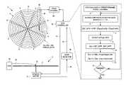
- FIGS. 1A–1Bshow a disk drive according to an embodiment of the present invention comprising a disk having a plurality of servo wedges, a head actuated over the disk, and a disk controller for estimating a sinusoidal error in a wedge time period (WTP).
- WTPwedge time period
- FIG. 2is a flow diagram according to an embodiment of the present invention for estimating the sinusoidal error in the WTP by estimating coefficients of the sinusoid using closed-loop feedback.
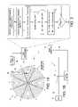
- FIG. 3Ashows an embodiment of the present invention wherein a wedge time counter is used to detect an actual WTP.
- FIG. 3Bshows an embodiment of the present invention wherein a wedge period counter is loaded with a nominal value adjusted by an eccentricity compensation value computed using the coefficients of the sinusoidal error in the WTP.
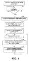
- FIG. 4is a flow diagram according to an embodiment of the present invention for using a compensated WTP for controlling the speed of a spindle motor.
- FIG. 5shows further details of the spindle control circuitry according to an embodiment of the present invention including a BEMF detector, a phased-locked-loop, BEMF detection window circuitry, a commutation sequencer, and a current modulator for generating a PWM current control signal.
- FIG. 6is a waveform showing the torque curves generated by the windings of a three-phase spindle motor and an associated commutation interval.
- FIG. 7is a flow diagram according to an embodiment of the present invention for spinning the disk up to the operating speed, calibrating a default at-speed current, and switching from the BEMF spindle speed control mode to wedge spindle speed control mode.
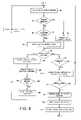
- FIG. 8is a flow diagram according to an embodiment of the present invention wherein a spindle control current is updated in response to a wedge speed error generated by accumulating a predetermined number of wedge time periods to generate a wedge time period and comparing the wedge time period to a reference time period.
- FIG. 9shows an embodiment of the present invention wherein a frequency synthesizer is used to generate a write clock at a frequency that accounts for the eccentricity in the rotation of the disk to thereby maintain a substantially constant linear bit density.
- FIGS. 1A–1Bshow a disk drive 2 according to an embodiment of the present invention comprising a disk 4 having a plurality of tracks 6 , wherein each track comprises a plurality of data sectors and a plurality of servo sectors forming N servo wedges 8 , and a wedge time period (WTP) occurs between each servo wedge 8 .
- a head 10is actuated over the disk 4 , and a disk controller 22 executes the flow diagram of FIG. 2 to estimate a sinusoidal error in the WTP due to eccentricity in the disk 4 rotating.
- an actual WTPis detected by detecting an interval between the head 10 passing over a first and second servo wedge 8 .
- a wedge time error e(k)is estimated as the difference between the estimated WTP and the detected actual WTP.
- step 15the above steps of calculating an estimated WTP, detecting an actual WTP, estimating a wedge time error e(k), and adjusting the coefficients ⁇ â, ⁇ circumflex over (b) ⁇ are repeated at least once, for example, until the wedge time error e(k) falls below a predetermined threshold.
- the present inventionuses closed-loop feedback, the above equation will converge to an accurate estimate of the coefficients ⁇ â, ⁇ circumflex over (b) ⁇ within fewer revolutions of the disk as compared to the prior art technique of computing a single-point DFT.
- the number of iterations to compute the coefficients using the above equationis determined based on a fixed number of disk revolutions.
- the iterationsare terminated once the wedge time error e(k) falls below a predetermined threshold thereby minimizing the number of disk revolutions.
- the flow diagram of FIG. 2is executed over a number of different radial locations (different tracks 6 ) to account for the change in the sinusoidal error relative to the radial location of the head 10 .
- the disk driveis partitioned into a number of zones wherein each zone comprises a predetermined band of tracks.
- the flow diagramis executed for a selected track in each zone (e.g., the middle track) and the resulting coefficients ⁇ â, ⁇ circumflex over (b) ⁇ used for each track in the zone.
- a suitable interpolation techniquemay also be employed to calculate the coefficients ⁇ â, ⁇ circumflex over (b) ⁇ based on the radial location (track number), for example, using a suitable curve fitting polynomial.
- FIG. 3Ashows an embodiment of the present invention wherein a wedge time counter 17 is clocked at a predetermined frequency.
- a sync mark detector 19detects a sync mark in the servo wedge 8
- the value of the wedge time counter 17is latched as a servo time stamp.
- the actual WTP detected at step 9 of FIG. 2is then computed as the difference between consecutive servo time stamps (wedge time counter values).
- the coefficients ⁇ â, ⁇ circumflex over (b) ⁇may be used in any suitable manner to enhance the operation of the disk drive 2 .
- the coefficients ⁇ â, ⁇ circumflex over (b) ⁇are used to enable the sync mark detector 19 at the appropriate time by opening a sync mark detection window commensurate with the head 10 approaching a servo sync mark.
- a wedge period counter 21is loaded with a count value corresponding to the estimated WTP for the current servo wedge.
- the count valueis computed by adding 23 the RTP 25 to an eccentricity compensation value 29 computed 27 using the coefficients ⁇ â, ⁇ circumflex over (b) ⁇ as a function of the wedge number and track number.
- the eccentricity compensation values 29may be computed 27 using any suitable technique such as a lookup table or curve fitting polynomial.
- the RTP 25may also be generated using any suitable technique, such as computing the average WTP over a revolution of the disk during a calibration mode. After loading the wedge period counter 21 with the estimated WTP value, the wedge period counter 21 is decremented at a predetermined frequency and then opens the sync mark detection window when the wedge period counter 21 underflows.
- the coefficients ⁇ â, ⁇ circumflex over (b) ⁇are used to estimate the WTP for use in controlling the speed of a spindle motor 12 shown in FIG. 1B .
- the spindle motor 12rotates the disk 4 at an operating speed in response to a spindle control current 14 , wherein the spindle motor 12 comprises a plurality of windings which generate a back electromotive force (BEMF) voltage 16 .
- BEMF detector 18generates a BEMF signal 20 by comparing the BEMF voltage 16 to a threshold.
- the disk controller 22executes the steps of the flow diagram shown in FIG.
- a BEMF speed erroris generated in response to the BEMF signal 20 during the BEMF spindle speed control mode, and the spindle control current 14 is updated in response to the BEMF speed error to drive the disk 4 at the operating speed. If at step 26 the BEMF speed error is substantially zero, at step 28 a reference time period is calibrated by accumulating a predetermined number of WTPs. At step 30 the coefficients ⁇ â, ⁇ circumflex over (b) ⁇ for generating the estimated WTPs are computed by executing the flow diagram of FIG.
- the disk controller 22switches to the wedge spindle speed control mode.
- an actual WTPis detected, and at step 34 a wedge speed error is generated representing a difference between the RTP and the detected actual WTP adjusted by an eccentricity compensation value computed from the coefficients ⁇ â, ⁇ circumflex over (b) ⁇ .
- the eccentricity compensation values computed at step 34 of FIG. 4are computed as a function of the current wedge number and track number.
- the disk 4is maintained at the operating speed by updating the spindle control current 14 in response to the wedge speed error.
- the head 10is connected to a distal end of an actuator arm 36 which is rotated about a pivot by a voice coil motor (VCM) 38 in order to actuate the head 10 radially over the disk 4 .
- VCMvoice coil motor
- a read channel 40processes the read signal emanating from the head 10 and detects an estimated binary sequence representing the data recorded on the disk 4 .
- the read channel 40also detects the sync marks in the servo wedges 8 used to update the wedge time counter 17 of FIG. 3A .
- the read channel 40may be implemented as a separate integrated circuit, or integrated with the disk controller 22 in a “system on a chip”.
- the BEMF detector 18may be integrated into the disk controller 22 or implemented in a separate servo controller chip.
- FIG. 5shows a spindle motor 12 according to an embodiment of the present invention comprising three windings connected at a center tap forming three phases ( ⁇ A, ⁇ B, ⁇ C); however, any suitable spindle motor comprising any suitable number of windings in any suitable configuration implementing any suitable number of phases may be employed.
- FIG. 5also shows details of spindle driver circuitry comprising three sets of commutation switches 42 A– 42 C each comprising a first field effect transistor (FET) for connecting a respective winding to a power supply Vpwr 44 and a second FET for connecting the respective winding to ground 46 .
- FETfield effect transistor
- a commutation sequencer 48generates a control signal 50 applied to the commutation switches 42 A– 42 C in order to drive current from the power supply 44 through the appropriate windings to ground 46 as determined from the commutation state.
- the commutation sequencer 48may control the commutation switches 42 A– 42 C in any suitable manner, such as in a conventional bipolar commutation sequence, tripolar commutation sequence, or hybrid bipolar-tripolar commutation sequence as disclosed in U.S. Pat. No. 5,808,440, the disclosure of which is incorporated herein by reference.
- the amount of torque generated by the spindle motor 12is determined by the angular position of the rotor with respect to the stator, the magnitude of the current driving the windings, and a torque constant Kt.
- the torque constant Ktis a function of the number of turns in the windings as well as the strength of the permanent magnets.
- FIG. 6illustrates the torque curves for the three-phase spindle motor 12 of FIG. 5 , where the three dashed-line sine waves KtA, KtB, and KtC correspond to the torque profile for each phase of the spindle motor.
- the desired torque output(shown as a solid line) is generated by changing the commutation state at the appropriate commutation interval Tc.
- the appropriate commutation intervalcan be determined by detecting zero crossings in the BEMF voltage 16 generated by the un-energized winding.
- a commutation clock 52is generated by a phase-locked-loop (PLL) 54 which locks onto the frequency of the BEMF zero crossings signal 20 .
- the commutation clock 52is applied to the commutation sequencer 48 and a BEMF speed control block 56 .
- the BEMF speed control block 56computes the BEMF speed error as the difference between an actual and desired frequency of the BEMF zero crossings signal 20 , and implements a compensator for generating a BEMF spindle control current command 58 in response to the BEMF speed error.
- a current modulator 68adjusts a duty cycle of a PWM signal 14 (spindle control current 14 in FIG. 1A ) in response to the BEMF spindle control current command 58 which controls the amount of current flowing through the energized windings, and therefore the amount of torque output and speed of the spindle motor 12 .
- BEMF detection window circuitry 59periodically disables the PWM signal 14 (e.g., holds the PWM signal 14 high) for a predetermined interval (detection window) to attenuate noise in the BEMF voltage 16 while the BEMF detector 18 compares the BEMF voltage 16 to the threshold.
- the timing of the BEMF detection windowis determined from the commutation clock 52 .
- a wedge speed control block 60generates the wedge speed error in response to the servo wedges 8 , the reference time period (RTP), and the eccentricity compensation values.
- the wedge speed control block 60implements a compensator for generating a wedge spindle control current command 62 in response to the wedge speed error.
- the compensator implemented in the wedge speed control block 60has a higher bandwidth than the compensator implemented by the BEMF speed control block 56 .
- a multiplexer 64 controlled by signal B/W 65selects between the BEMF spindle control current command 58 and the wedge spindle control current command 62 as the control current command 66 applied to the current modulator 68 .
- the current modulator 68fixes the duty cycle of the PWM signal 14 in response to an at-speed current command 74 so that the at-speed current is applied to the windings.
- the B/W signal 65also disables the BEMF detection window circuitry 59 while the speed of the spindle motor 12 is controlled in response to the wedge speed error. This embodiment helps reduce acoustic noise caused by current transients that occur when the PWM signal 14 is disabled (e.g., held high) during the detection window.
- the B/W signal 65configures the PLL 54 to output a fixed frequency commutation clock 52 corresponding to the at-speed frequency.
- the PLL 54continues to generate the commutation clock 52 in response to the BEMF signal 20 even though it may be less reliable due to the noise induced into the BEMF voltage 16 by the switching action of the PWM signal 14 .
- a wedge time counteris incremented at a predetermined frequency.
- a predetermined number of wedge time counter valuesare accumulated representing a predetermined number of WTPs.
- This embodimentis illustrated in the flow diagram of FIGS. 7 and 8 .
- the BEMF detector 18is enabled and the disk 4 is spun up to the operating speed by updating the spindle control current 14 in response to the BEMF speed error 58 .
- a reference time periodis calibrated at step 78 .
- the RTPis generated by accumulating a predetermined number of wedge time counter values.
- the wedge time counter value(adjusted by a corresponding eccentricity compensation value) is summed into the RTP (unless a servo wedge error is encountered as described below, in which case the wedge time counter value is ignored).
- the wedge time counteris reset at each servo wedge 8 , and in another embodiment, the wedge time counter is free running and the WTP is determined from the incremented wedge time counter value from wedge to wedge.
- the coefficients ⁇ â, ⁇ circumflex over (b) ⁇ for generating the estimated WTPsare computed by executing the flow diagram of FIG. 2 , and in one embodiment, over a number of different radial locations of the disk 4 .
- a default at-speed currentis calibrated which is the spindle control current 14 that generates a substantially zero BEMF speed error.
- the default at-speed currentis used as the spindle control current 14 if an error condition is detected immediately after transitioning into the wedge speed control mode. Otherwise, the at-speed current is updated while the wedge speed error is substantially zero when controlling the spindle motor 12 in the wedge speed control mode.
- the wedge time counter values(adjusted by corresponding eccentricity compensation values) are accumulated until at step 82 N wedge-to-wedge times have been accumulated into a wedge time period. If so, at step 84 the spindle control current 14 is updated in response to the wedge speed error computed by subtracting the wedge time period from the reference time period.
- the BEMF detection window circuitry 59is disabled, the wedge spindle speed control mode is enabled, and at step 88 a time-out counter for timing a time-out interval is reset. Any suitable time-out interval may be employed.
- N wedge time counter valuesare accumulated to generate the wedge speed error, and the time-out interval is configured to M*N servo wedges 8 (where M is greater than 1 e.g., 1.5). That is, an error condition is detected if N wedge time counter values have not been accumulated within M*N servo wedges 8 .
- Controlthen continues at step 90 of FIG. 8 wherein the next servo wedge 8 is detected. If a servo wedge error occurs, which may include an inability to synchronize to a servo wedge due to a burst error or detection of a bad track ID at step 92 , or a bad wedge time counter value at step 94 , then at step 96 the wedge time counter value is ignored. A bad wedge time counter value may be detected at step 94 , for example, if a servo wedge is missed altogether. If a servo wedge error is not detected, then at step 98 the wedge counter value adjusted by an eccentricity compensation value is summed into the estimated WTP.
- the eccentricity compensation valueis computed from the coefficients ⁇ â, ⁇ circumflex over (b) ⁇ for estimating the sinusoidal error in the WTP, and similar to the eccentricity compensation values 29 of FIG. 3B , in one embodiment the eccentricity compensation values are computed as a function of the current wedge number and track number. If at step 100 N wedge time counter values have been accumulated, then at step 102 the wedge speed error is computed by subtracting the WTP from the RTP. At step 104 the spindle control current 14 is updated in response to the wedge speed error. If at step 106 the wedge speed error is zero (or substantially zero), then at step 108 the at-speed current is updated with the spindle control current 14 . Some form of averaging may be employed to filter noisy or erroneous spindle control current values. At step 110 the timer for timing the time-out interval is reset, and the process continues at step 90 .
- step 100If at step 100 N wedge time counter values have not been accumulated and at step 112 the time-out interval expires, then an error condition is detected and at step 114 the spindle control current 14 is set to the at-speed current. Setting the spindle control current 14 to the at-speed current helps maintain the disk at the operating speed until the error condition subsides. If at step 116 a revolution of the disk 4 has not occurred without updating the spindle control current 14 , then control branches back to step 90 to detect the next servo wedge. Because the time-out interval has not been reset, control will branch to step 112 and step 114 until N wedge time counter values have been accumulated at step 100 .
- the disk controller 22transitions back into the BEMF spindle speed control mode.
- the BEMF detection window circuitry 59is enabled, and after waiting two revolutions of the disk 4 at step 120 to allow the BEMF speed error 58 to settle, the BEMF spindle speed control mode is enabled at step 122 and control branches to step 82 of FIG. 7 .
- the disk controller 22remains in the BEMF spindle speed control mode until again N wedge time counter values are accumulated at step 82 and the spindle control current 14 is updated at step 84 .
- the disk controller 22switches from the wedge spindle speed control mode to the BEMF spindle speed control mode without having detected an error. For example, during a calibration procedure the disk controller 22 may seek the head 10 to a calibration track where the timing between servo wedges 8 changes such that the reference time period is no longer valid. In addition, the disk controller 22 may switch from wedge spindle speed control to BEMF spindle speed control to perform certain test during manufacturing, such as resonance discover of the spindle motor 12 . After disabling the wedge spindle speed control mode the disk controller 22 sets the spindle control current 14 to the at-speed current 74 for a predetermined interval (e.g., two revolutions of the disk) to allow the BEMF speed error 58 to settle. Once the BEMF speed error 58 settles, the disk controller 22 can transition safely into the BEMF spindle speed control mode.
- a predetermined intervale.g., two revolutions of the disk
- FIG. 9shows an embodiment of the present invention wherein coefficients ⁇ â, ⁇ circumflex over (b) ⁇ for estimating the sinusoidal error in the WTP are used to adjust the write frequency to achieve a substantially constant linear bit density. That is, the coefficients ⁇ â, ⁇ circumflex over (b) ⁇ are used to compensate for the sinusoidal speed variations due to the eccentricity in the disk rotating.
- An eccentricity compensation value 124is computed 125 using coefficients ⁇ â, ⁇ circumflex over (b) ⁇ as a function of the current wedge number and track number.
- the eccentricity compensation value 124is added 126 to a base frequency control signal 128 generated 130 as a function of the current track number (which corresponds to the current zone).
- the resulting compensated control signal 132is applied to a frequency synthesizer 134 which generates a write clock 136 at a frequency that compensates for the sinusoidal speed variation as the disk rotates.
- a read clock 138is generated by read clock circuitry 140 at a frequency that substantially matches the write clock 136 for the current wedge number and track number.
- the read channel 40 of FIG. 1Amay comprise any suitable modulation/demodulation circuitry for writing data to and reading data from the disk.
- the read channel 40comprises suitable partial-response/maximum-likelihood (PRML) circuitry, such as timing recovery circuitry, equalizing circuitry, and a Viterbi type sequence detector.
- PRMLpartial-response/maximum-likelihood
- the write clock 136clocks a preamp circuit to write data to the disk at a predetermined baud rate (write clock frequency).
- baud ratewrite clock frequency
- read signal samples valuesare generated synchronous to the baud rate and an estimated data sequence detected from the synchronous read signal sample values.
- the synchronous read signal sample valuesmay be generated in any suitable manner, such as clocking a sampling device so as to sample the read signal synchronously (at a read clock frequency synchronized to the baud rate) or by sampling the read signal asynchronously and using an interpolation filter to generate synchronous read signal sample values.
- the eccentricity compensation valuesmay be used to generate the synchronous sample values, for example, by generating an initial input frequency to a synchronous sampling phase locked loop (PLL), or by generating an asynchronous sampling clock for interpolated timing recovery.
- PLLsynchronous sampling phase locked loop
- eccentricity compensation valuesmay not be necessary to use the eccentricity compensation values to generate the synchronous sample values as long as the preamble is of sufficient length to lock the PLL when using synchronous sampling timing recovery, and as long as the interpolation filter has sufficient resolution and range when using interpolated timing recovery.
Landscapes
- Moving Of The Head To Find And Align With The Track (AREA)
Abstract
Description
EST_WTP=RTP+â*cos(2πk/N)+{circumflex over (b)}*sin(2πk/N)
wherein RTP is a reference time period corresponding to a nominal WTP, k is an index representing one of the servo wedges, and {â,{circumflex over (b)}} are adjustable coefficients. An actual WTP is detected by detecting an interval between the head passing over a first and second servo wedge, and a wedge time error e(k) is estimated as the difference between the estimated WTP and the detected actual WTP. The coefficients {â,{circumflex over (b)}} for generating the estimated WTP are adjusted according to:
â(k+1)=â(k)−G*e(k)*cos(2πk/N)
{circumflex over (b)}(k+1)={circumflex over (b)}(k)−G*e(k)*sin(2πk/N)
wherein G is a predetermined gain. The above steps of calculating an estimated WTP, detecting an actual WTP, estimating a wedge time error e(k), and adjusting the coefficients {â,{circumflex over (b)}} are repeated at least once, for example, until the wedge time error e(k) falls below a predetermined threshold.
EST_WTP=RTP+â*cos(2πk/N)+{circumflex over (b)}*sin(2πk/N)
wherein RTP is a reference time period corresponding to a nominal WTP, k is an index representing one of the servo wedges, and {â,{circumflex over (b)}} are adjustable coefficients. An actual WTP is detected by detecting an interval between the head passing over a first and second servo wedge, and a wedge time error e(k) is estimated as the difference between the estimated WTP and the detected actual WTP. The coefficients {â,{circumflex over (b)}} for generating the estimated WTP are adjusted according to:
â(k+1)=â(k)−G*e(k)*cos(2k/N)
{circumflex over (b)}(k+1)={circumflex over (b)}(k)−G*e(k)*sin(2πk/N)
wherein G is a predetermined gain. The above steps of calculating an estimated WTP, detecting an actual WTP, estimating a wedge time error e(k), and adjusting the coefficients {â,{circumflex over (b)}} are repeated at least once, for example, until the wedge time error e(k) falls below a predetermined threshold.
EST_WTP=RTP+â*cos(2πk/N)+*sin(2πk/N)
wherein RTP is a reference time period corresponding to a nominal WTP, k is an index representing one of the servo wedges, and {â,{circumflex over (b)}} are adjustable coefficients. At
â(k+1)=â(k)−G*e(k)*cos(2πk/N)
{circumflex over (b)}(k+1)={circumflex over (b)}(k)−G*e(k)*sin(2πk/N)
wherein G is a predetermined gain. At
Claims (6)
EST_WTP=RTP+â*cos(2πk/N)+{circumflex over (b)}*sin(2πk/N)
â(k+1)=â(k)−G*e(k)*cos(2πk/N)
{circumflex over (b)}(k+1)={circumflex over (b)}(k)−G*e(k)*sin(2πk/N)
EST_WTP=RTP+â*cos(2πk/N)+{circumflex over (b)}*sin(2πk/N)
â(k+1)=â(k)−G*e(k)*cos(2πk/N)
{circumflex over (b)}(k+1)={circumflex over (b)}(k)−G*e(k)*sin(2πk/N)
Priority Applications (1)
| Application Number | Priority Date | Filing Date | Title |
|---|---|---|---|
| US10/989,674US7068451B1 (en) | 2004-11-16 | 2004-11-16 | Disk drive estimating a sinusoidal error in a wedge time period due to eccentricity in disk rotation |
Applications Claiming Priority (1)
| Application Number | Priority Date | Filing Date | Title |
|---|---|---|---|
| US10/989,674US7068451B1 (en) | 2004-11-16 | 2004-11-16 | Disk drive estimating a sinusoidal error in a wedge time period due to eccentricity in disk rotation |
Publications (1)
| Publication Number | Publication Date |
|---|---|
| US7068451B1true US7068451B1 (en) | 2006-06-27 |
Family
ID=36600508
Family Applications (1)
| Application Number | Title | Priority Date | Filing Date |
|---|---|---|---|
| US10/989,674Expired - Fee RelatedUS7068451B1 (en) | 2004-11-16 | 2004-11-16 | Disk drive estimating a sinusoidal error in a wedge time period due to eccentricity in disk rotation |
Country Status (1)
| Country | Link |
|---|---|
| US (1) | US7068451B1 (en) |
Cited By (138)
| Publication number | Priority date | Publication date | Assignee | Title |
|---|---|---|---|---|
| US7215496B1 (en)* | 2004-10-20 | 2007-05-08 | Western Digital Technologies, Inc. | Disk drive having adaptively-sized sectors to compensate for disk eccentricity |
| US20070164691A1 (en)* | 2005-09-29 | 2007-07-19 | Agile Systems Inc. | System and method for attenuating noise associated with a back electromotive force signal in a motor |
| US7251098B1 (en)* | 2004-11-19 | 2007-07-31 | Western Digital Technologies, Inc. | Disk drive adjusting write clock frequency to compensate for eccentricity in disk rotation |
| US7391584B1 (en) | 2006-11-07 | 2008-06-24 | Western Digital Technologies, Inc. | Compensating for repeatable phase error when servo writing a disk drive from spiral tracks |
| US20080158711A1 (en)* | 2006-12-31 | 2008-07-03 | Broadcom Corporation | Delta-sigma PLL using fractional divider from a multiphase ring oscillator |
| US7440225B1 (en) | 2006-08-21 | 2008-10-21 | Western Digital Technologies, Inc. | Disk drive employing pivot friction compensation |
| US7551390B1 (en) | 2007-08-21 | 2009-06-23 | Western Digital Technologies, Inc. | Disk drive to characterize misaligned servo wedges |
| US20090195936A1 (en)* | 2008-02-04 | 2009-08-06 | Western Digital Technologies, Inc. | Disk drive servoing off of first head while determining fly height for second head |
| US7583466B2 (en) | 2007-11-15 | 2009-09-01 | Western Digital (Fremont), Llc | Disk drive determining operating fly height by detecting head disk contact from disk rotation time |
| US7675707B1 (en) | 2008-11-21 | 2010-03-09 | Western Digital Technologies, Inc. | Disk drive employing repeatable disturbance compensation for fly height control |
| US20100079888A1 (en)* | 2008-09-29 | 2010-04-01 | Wd Media, Inc. | Eccentricity determination for a disk |
| US7839595B1 (en) | 2008-01-25 | 2010-11-23 | Western Digital Technologies, Inc. | Feed forward compensation for fly height control in a disk drive |
| US7916420B1 (en) | 2010-05-14 | 2011-03-29 | Western Digital Technologies, Inc. | Disk drive employing comb filter for repeatable fly height compensation |
| US8059357B1 (en) | 2010-03-18 | 2011-11-15 | Western Digital Technologies, Inc. | Disk drive adjusting fly height when calibrating head/disk contact |
| US8300338B1 (en) | 2010-09-30 | 2012-10-30 | Western Digital Technologies, Inc. | Disk drive correlating different fly height measurements to verify disk warpage |
| US8320069B1 (en) | 2010-03-18 | 2012-11-27 | Western Digital Technologies, Inc. | Disk drive detecting positive correlation in fly height measurements |
| US8482873B1 (en) | 2008-02-18 | 2013-07-09 | Western Digital Technologies, Inc. | Disk drive employing pulse width modulation of head control signal |
| US8654466B1 (en) | 2011-11-21 | 2014-02-18 | Western Digital Technologies, Inc. | Calculation of head media separation (HMS) from servo preamble in a hard disk drive |
| US8670206B1 (en) | 2012-03-27 | 2014-03-11 | Western Digital Technologies, Inc. | Disk drive estimating repeatable runout of reference pattern based on repeatable runout of phase error |
| US8699159B1 (en) | 2012-06-18 | 2014-04-15 | Western Digital Technologies, Inc. | Reducing effects of wide area track erasure in a disk drive |
| US8717704B1 (en) | 2012-02-28 | 2014-05-06 | Western Digital Technologies, Inc. | Disk drive defining non-circular data tracks relative to a rotation axis of the disk |
| US8724253B1 (en) | 2012-03-27 | 2014-05-13 | Western Digital Technologies, Inc. | Disk drive adjusting demodulation window for spiral track using timing feed-forward compensation |
| US8730612B1 (en) | 2011-12-16 | 2014-05-20 | Western Digital Technologies, Inc. | Disk drive evaluating ratio of fly height setting for first and second heads to verify operability |
| US8743495B1 (en) | 2011-06-03 | 2014-06-03 | Western Digital Technologies, Inc. | Disk drive detecting track squeeze when circular tracks are defined from non-circular servo tracks |
| US8749904B1 (en) | 2012-02-28 | 2014-06-10 | Western Digital Technologies, Inc. | Disk drive compensating for track squeeze by writing non-circular servo tracks |
| US8767332B1 (en) | 2013-04-03 | 2014-07-01 | Western Digital Technologies, Inc. | Disk drive predicting off-track error due to disturbances occurring over different frequency ranges |
| US8773807B1 (en) | 2012-07-24 | 2014-07-08 | Western Digital Technologies, Inc. | Disk drive calibrating fly height during startup by reading spacing pattern in servo sectors |
| US8773802B1 (en) | 2010-08-24 | 2014-07-08 | Western Digital Technologies, Inc. | Disk drive resetting fly height reference generated from a degrading calibration track |
| US8824081B1 (en) | 2012-03-13 | 2014-09-02 | Western Digital Technologies, Inc. | Disk drive employing radially coherent reference pattern for servo burst demodulation and fly height measurement |
| US8830617B1 (en) | 2013-05-30 | 2014-09-09 | Western Digital Technologies, Inc. | Disk drive adjusting state estimator to compensate for unreliable servo data |
| US8879188B1 (en) | 2010-08-23 | 2014-11-04 | Western Digital Technologies, Inc. | Disk drive employing fly height calibration tracks to account for magnetic entropy and thermal decay |
| US8879191B1 (en) | 2012-11-14 | 2014-11-04 | Western Digital Technologies, Inc. | Disk drive modifying rotational position optimization algorithm to achieve target performance for limited stroke |
| US8885279B1 (en) | 2010-08-30 | 2014-11-11 | Western Digital Technologies, Inc. | Disk drive detecting head/disk contact by evaluating a subset of touchdown metrics during a servo sector interrupt |
| US8891194B1 (en) | 2013-05-14 | 2014-11-18 | Western Digital Technologies, Inc. | Disk drive iteratively adapting correction value that compensates for non-linearity of head |
| US8891191B1 (en) | 2014-05-06 | 2014-11-18 | Western Digital Technologies, Inc. | Data storage device initializing read signal gain to detect servo seed pattern |
| US8896957B1 (en) | 2013-05-10 | 2014-11-25 | Western Digital Technologies, Inc. | Disk drive performing spiral scan of disk surface to detect residual data |
| US8902538B1 (en) | 2013-03-29 | 2014-12-02 | Western Digital Technologies, Inc. | Disk drive detecting crack in microactuator |
| US8902539B1 (en) | 2014-05-13 | 2014-12-02 | Western Digital Technologies, Inc. | Data storage device reducing seek power consumption |
| US8913342B1 (en) | 2014-03-21 | 2014-12-16 | Western Digital Technologies, Inc. | Data storage device adjusting range of microactuator digital-to-analog converter based on operating temperature |
| US8917475B1 (en) | 2013-12-20 | 2014-12-23 | Western Digital Technologies, Inc. | Disk drive generating a disk locked clock using radial dependent timing feed-forward compensation |
| US8917474B1 (en) | 2011-08-08 | 2014-12-23 | Western Digital Technologies, Inc. | Disk drive calibrating a velocity profile prior to writing a spiral track |
| US8922937B1 (en) | 2012-04-19 | 2014-12-30 | Western Digital Technologies, Inc. | Disk drive evaluating multiple vibration sensor outputs to enable write-protection |
| US8922940B1 (en) | 2014-05-27 | 2014-12-30 | Western Digital Technologies, Inc. | Data storage device reducing spindle motor voltage boost during power failure |
| US8922938B1 (en) | 2012-11-02 | 2014-12-30 | Western Digital Technologies, Inc. | Disk drive filtering disturbance signal and error signal for adaptive feed-forward compensation |
| US8922931B1 (en) | 2013-05-13 | 2014-12-30 | Western Digital Technologies, Inc. | Disk drive releasing variable amount of buffered write data based on sliding window of predicted servo quality |
| US8929021B1 (en) | 2012-03-27 | 2015-01-06 | Western Digital Technologies, Inc. | Disk drive servo writing from spiral tracks using radial dependent timing feed-forward compensation |
| US8929022B1 (en) | 2012-12-19 | 2015-01-06 | Western Digital Technologies, Inc. | Disk drive detecting microactuator degradation by evaluating frequency component of servo signal |
| US8934192B1 (en) | 2008-11-24 | 2015-01-13 | Western Digital Technologies, Inc. | Disk drive determining operating fly height by detecting head disk contact from read signal amplitude variance |
| US8934186B1 (en) | 2014-03-26 | 2015-01-13 | Western Digital Technologies, Inc. | Data storage device estimating servo zone to reduce size of track address |
| US8937784B1 (en) | 2012-08-01 | 2015-01-20 | Western Digital Technologies, Inc. | Disk drive employing feed-forward compensation and phase shift compensation during seek settling |
| US8941945B1 (en) | 2014-06-06 | 2015-01-27 | Western Digital Technologies, Inc. | Data storage device servoing heads based on virtual servo tracks |
| US8941939B1 (en) | 2013-10-24 | 2015-01-27 | Western Digital Technologies, Inc. | Disk drive using VCM BEMF feed-forward compensation to write servo data to a disk |
| US8947819B1 (en) | 2012-08-28 | 2015-02-03 | Western Digital Technologies, Inc. | Disk drive implementing hysteresis for primary shock detector based on a more sensitive secondary shock detector |
| US8953271B1 (en) | 2013-05-13 | 2015-02-10 | Western Digital Technologies, Inc. | Disk drive compensating for repeatable run out selectively per zone |
| US8953278B1 (en) | 2011-11-16 | 2015-02-10 | Western Digital Technologies, Inc. | Disk drive selecting disturbance signal for feed-forward compensation |
| US8958169B1 (en) | 2014-06-11 | 2015-02-17 | Western Digital Technologies, Inc. | Data storage device re-qualifying state estimator while decelerating head |
| US8970979B1 (en) | 2013-12-18 | 2015-03-03 | Western Digital Technologies, Inc. | Disk drive determining frequency response of actuator near servo sample frequency |
| US8982490B1 (en) | 2014-04-24 | 2015-03-17 | Western Digital Technologies, Inc. | Data storage device reading first spiral track while simultaneously writing second spiral track |
| US8982501B1 (en)* | 2014-09-22 | 2015-03-17 | Western Digital Technologies, Inc. | Data storage device compensating for repeatable disturbance when commutating a spindle motor |
| US8995082B1 (en) | 2011-06-03 | 2015-03-31 | Western Digital Technologies, Inc. | Reducing acoustic noise in a disk drive when exiting idle mode |
| US8995075B1 (en) | 2012-06-21 | 2015-03-31 | Western Digital Technologies, Inc. | Disk drive adjusting estimated servo state to compensate for transient when crossing a servo zone boundary |
| US9001454B1 (en) | 2013-04-12 | 2015-04-07 | Western Digital Technologies, Inc. | Disk drive adjusting phase of adaptive feed-forward controller when reconfiguring servo loop |
| US9007714B1 (en) | 2014-07-18 | 2015-04-14 | Western Digital Technologies Inc. | Data storage device comprising slew rate anti-windup compensation for microactuator |
| US9013824B1 (en) | 2014-06-04 | 2015-04-21 | Western Digital Technologies, Inc. | Data storage device comprising dual read sensors and dual servo channels to improve servo demodulation |
| US9013825B1 (en) | 2014-03-24 | 2015-04-21 | Western Digital Technologies, Inc. | Electronic system with vibration management mechanism and method of operation thereof |
| US9026728B1 (en) | 2013-06-06 | 2015-05-05 | Western Digital Technologies, Inc. | Disk drive applying feed-forward compensation when writing consecutive data tracks |
| US9025269B1 (en) | 2014-01-02 | 2015-05-05 | Western Digital Technologies, Inc. | Disk drive compensating for cycle slip of disk locked clock when reading mini-wedge |
| US9047919B1 (en) | 2013-03-12 | 2015-06-02 | Western Digitial Technologies, Inc. | Disk drive initializing servo read channel by reading data preceding servo preamble during access operation |
| US9047901B1 (en) | 2013-05-28 | 2015-06-02 | Western Digital Technologies, Inc. | Disk drive measuring spiral track error by measuring a slope of a spiral track across a disk radius |
| US9047932B1 (en) | 2014-03-21 | 2015-06-02 | Western Digital Technologies, Inc. | Data storage device adjusting a power loss threshold based on samples of supply voltage |
| US9053727B1 (en) | 2014-06-02 | 2015-06-09 | Western Digital Technologies, Inc. | Disk drive opening spiral crossing window based on DC and AC spiral track error |
| US9053749B1 (en) | 2013-03-15 | 2015-06-09 | Western Digital Technologies, Inc. | Disk drive comprising a per-drive and per-head fly height filter |
| US9053726B1 (en) | 2014-01-29 | 2015-06-09 | Western Digital Technologies, Inc. | Data storage device on-line adapting disturbance observer filter |
| US9053712B1 (en) | 2014-05-07 | 2015-06-09 | Western Digital Technologies, Inc. | Data storage device reading servo sector while writing data sector |
| US9058826B1 (en) | 2014-02-13 | 2015-06-16 | Western Digital Technologies, Inc. | Data storage device detecting free fall condition from disk speed variations |
| US9058834B1 (en) | 2013-11-08 | 2015-06-16 | Western Digital Technologies, Inc. | Power architecture for low power modes in storage devices |
| US9058827B1 (en) | 2013-06-25 | 2015-06-16 | Western Digitial Technologies, Inc. | Disk drive optimizing filters based on sensor signal and disturbance signal for adaptive feed-forward compensation |
| US9064537B1 (en) | 2013-09-13 | 2015-06-23 | Western Digital Technologies, Inc. | Disk drive measuring radial offset between heads by detecting a difference between ramp contact |
| US9076490B1 (en) | 2012-12-12 | 2015-07-07 | Western Digital Technologies, Inc. | Disk drive writing radial offset spiral servo tracks by reading spiral seed tracks |
| US9076472B1 (en) | 2014-08-21 | 2015-07-07 | Western Digital (Fremont), Llc | Apparatus enabling writing servo data when disk reaches target rotation speed |
| US9076473B1 (en) | 2014-08-12 | 2015-07-07 | Western Digital Technologies, Inc. | Data storage device detecting fly height instability of head during load operation based on microactuator response |
| US9076471B1 (en) | 2013-07-31 | 2015-07-07 | Western Digital Technologies, Inc. | Fall detection scheme using FFS |
| US9093105B2 (en) | 2011-12-09 | 2015-07-28 | Western Digital Technologies, Inc. | Disk drive charging capacitor using motor supply voltage during power failure |
| US9099147B1 (en) | 2014-09-22 | 2015-08-04 | Western Digital Technologies, Inc. | Data storage device commutating a spindle motor using closed-loop rotation phase alignment |
| US9111575B1 (en) | 2014-10-23 | 2015-08-18 | Western Digital Technologies, Inc. | Data storage device employing adaptive feed-forward control in timing loop to compensate for vibration |
| US9117471B1 (en)* | 2014-12-19 | 2015-08-25 | Seagate Technology Llc | AC MR-offset compensation |
| US9129630B1 (en) | 2014-12-16 | 2015-09-08 | Western Digital Technologies, Inc. | Data storage device employing full servo sectors on first disk surface and mini servo sectors on second disk surface |
| US9142249B1 (en) | 2013-12-06 | 2015-09-22 | Western Digital Technologies, Inc. | Disk drive using timing loop control signal for vibration compensation in servo loop |
| US9142225B1 (en) | 2014-03-21 | 2015-09-22 | Western Digital Technologies, Inc. | Electronic system with actuator control mechanism and method of operation thereof |
| US9142235B1 (en) | 2009-10-27 | 2015-09-22 | Western Digital Technologies, Inc. | Disk drive characterizing microactuator by injecting sinusoidal disturbance and evaluating feed-forward compensation values |
| US9141177B1 (en) | 2014-03-21 | 2015-09-22 | Western Digital Technologies, Inc. | Data storage device employing glitch compensation for power loss detection |
| US9147428B1 (en) | 2013-04-24 | 2015-09-29 | Western Digital Technologies, Inc. | Disk drive with improved spin-up control |
| US9147418B1 (en) | 2013-06-20 | 2015-09-29 | Western Digital Technologies, Inc. | Disk drive compensating for microactuator gain variations |
| US9153283B1 (en) | 2014-09-30 | 2015-10-06 | Western Digital Technologies, Inc. | Data storage device compensating for hysteretic response of microactuator |
| US9165583B1 (en) | 2014-10-29 | 2015-10-20 | Western Digital Technologies, Inc. | Data storage device adjusting seek profile based on seek length when ending track is near ramp |
| US9171568B1 (en) | 2014-06-25 | 2015-10-27 | Western Digital Technologies, Inc. | Data storage device periodically re-initializing spindle motor commutation sequence based on timing data |
| US9171567B1 (en) | 2014-05-27 | 2015-10-27 | Western Digital Technologies, Inc. | Data storage device employing sliding mode control of spindle motor |
| US9208810B1 (en) | 2014-04-24 | 2015-12-08 | Western Digital Technologies, Inc. | Data storage device attenuating interference from first spiral track when reading second spiral track |
| US9208815B1 (en) | 2014-10-09 | 2015-12-08 | Western Digital Technologies, Inc. | Data storage device dynamically reducing coast velocity during seek to reduce power consumption |
| US9208808B1 (en) | 2014-04-22 | 2015-12-08 | Western Digital Technologies, Inc. | Electronic system with unload management mechanism and method of operation thereof |
| US9214175B1 (en) | 2015-03-16 | 2015-12-15 | Western Digital Technologies, Inc. | Data storage device configuring a gain of a servo control system for actuating a head over a disk |
| US9230592B1 (en) | 2014-12-23 | 2016-01-05 | Western Digital Technologies, Inc. | Electronic system with a method of motor spindle bandwidth estimation and calibration thereof |
| US9230593B1 (en) | 2014-12-23 | 2016-01-05 | Western Digital Technologies, Inc. | Data storage device optimizing spindle motor power when transitioning into a power failure mode |
| US9245540B1 (en) | 2014-10-29 | 2016-01-26 | Western Digital Technologies, Inc. | Voice coil motor temperature sensing circuit to reduce catastrophic failure due to voice coil motor coil shorting to ground |
| US9245577B1 (en) | 2015-03-26 | 2016-01-26 | Western Digital Technologies, Inc. | Data storage device comprising spindle motor current sensing with supply voltage noise attenuation |
| US9245560B1 (en) | 2015-03-09 | 2016-01-26 | Western Digital Technologies, Inc. | Data storage device measuring reader/writer offset by reading spiral track and concentric servo sectors |
| US9251823B1 (en) | 2014-12-10 | 2016-02-02 | Western Digital Technologies, Inc. | Data storage device delaying seek operation to avoid thermal asperities |
| US9269386B1 (en) | 2014-01-29 | 2016-02-23 | Western Digital Technologies, Inc. | Data storage device on-line adapting disturbance observer filter |
| US9286925B1 (en) | 2015-03-26 | 2016-03-15 | Western Digital Technologies, Inc. | Data storage device writing multiple burst correction values at the same radial location |
| US9286927B1 (en) | 2014-12-16 | 2016-03-15 | Western Digital Technologies, Inc. | Data storage device demodulating servo burst by computing slope of intermediate integration points |
| US9343094B1 (en) | 2015-03-26 | 2016-05-17 | Western Digital Technologies, Inc. | Data storage device filtering burst correction values before downsampling the burst correction values |
| US9343102B1 (en) | 2015-03-25 | 2016-05-17 | Western Digital Technologies, Inc. | Data storage device employing a phase offset to generate power from a spindle motor during a power failure |
| US9349401B1 (en) | 2014-07-24 | 2016-05-24 | Western Digital Technologies, Inc. | Electronic system with media scan mechanism and method of operation thereof |
| US9350278B1 (en) | 2014-06-13 | 2016-05-24 | Western Digital Technologies, Inc. | Circuit technique to integrate voice coil motor support elements |
| US9355676B1 (en) | 2015-03-25 | 2016-05-31 | Western Digital Technologies, Inc. | Data storage device controlling amplitude and phase of driving voltage to generate power from a spindle motor |
| US9355667B1 (en) | 2014-11-11 | 2016-05-31 | Western Digital Technologies, Inc. | Data storage device saving absolute position at each servo wedge for previous write operations |
| US9361939B1 (en) | 2014-03-10 | 2016-06-07 | Western Digital Technologies, Inc. | Data storage device characterizing geometry of magnetic transitions |
| US9396751B1 (en) | 2015-06-26 | 2016-07-19 | Western Digital Technologies, Inc. | Data storage device compensating for fabrication tolerances when measuring spindle motor current |
| US9407015B1 (en) | 2014-12-29 | 2016-08-02 | Western Digital Technologies, Inc. | Automatic power disconnect device |
| US9418689B2 (en) | 2014-10-09 | 2016-08-16 | Western Digital Technologies, Inc. | Data storage device generating an operating seek time profile as a function of a base seek time profile |
| US9424871B1 (en) | 2012-09-13 | 2016-08-23 | Western Digital Technologies, Inc. | Disk drive correcting an error in a detected gray code |
| US9424868B1 (en) | 2015-05-12 | 2016-08-23 | Western Digital Technologies, Inc. | Data storage device employing spindle motor driving profile during seek to improve power performance |
| US9437237B1 (en) | 2015-02-20 | 2016-09-06 | Western Digital Technologies, Inc. | Method to detect power loss through data storage device spindle speed |
| US9437231B1 (en) | 2015-09-25 | 2016-09-06 | Western Digital Technologies, Inc. | Data storage device concurrently controlling and sensing a secondary actuator for actuating a head over a disk |
| US9454212B1 (en) | 2014-12-08 | 2016-09-27 | Western Digital Technologies, Inc. | Wakeup detector |
| US9471072B1 (en) | 2013-11-14 | 2016-10-18 | Western Digital Technologies, Inc | Self-adaptive voltage scaling |
| US9484733B1 (en) | 2013-09-11 | 2016-11-01 | Western Digital Technologies, Inc. | Power control module for data storage device |
| US9542966B1 (en) | 2015-07-09 | 2017-01-10 | Western Digital Technologies, Inc. | Data storage devices and methods with frequency-shaped sliding mode control |
| US9564162B1 (en) | 2015-12-28 | 2017-02-07 | Western Digital Technologies, Inc. | Data storage device measuring resonant frequency of a shock sensor by applying differential excitation and measuring oscillation |
| US9581978B1 (en) | 2014-12-17 | 2017-02-28 | Western Digital Technologies, Inc. | Electronic system with servo management mechanism and method of operation thereof |
| US9620160B1 (en) | 2015-12-28 | 2017-04-11 | Western Digital Technologies, Inc. | Data storage device measuring resonant frequency of a shock sensor by inserting the shock sensor into an oscillator circuit |
| US9823294B1 (en) | 2013-10-29 | 2017-11-21 | Western Digital Technologies, Inc. | Negative voltage testing methodology and tester |
| US9886285B2 (en) | 2015-03-31 | 2018-02-06 | Western Digital Technologies, Inc. | Communication interface initialization |
| US9899834B1 (en) | 2015-11-18 | 2018-02-20 | Western Digital Technologies, Inc. | Power control module using protection circuit for regulating backup voltage to power load during power fault |
| US9959204B1 (en) | 2015-03-09 | 2018-05-01 | Western Digital Technologies, Inc. | Tracking sequential ranges of non-ordered data |
| US10068609B1 (en) | 2017-02-23 | 2018-09-04 | Marvell International Ltd. | Variable frequency write pattern generation |
| US10783912B1 (en)* | 2019-05-22 | 2020-09-22 | Western Digital Technologies, Inc. | Calibrating elevator actuator for disk drive |
| US11417363B1 (en) | 2021-06-25 | 2022-08-16 | Western Digital Technologies, Inc. | Data storage device calibrating write parameter by pressing actuator against crash stop |
Citations (17)
| Publication number | Priority date | Publication date | Assignee | Title |
|---|---|---|---|---|
| US5297131A (en)* | 1991-05-31 | 1994-03-22 | Sony Corporation | Eccentricity detection and compensation of a disk by a preformatted encoding pattern |
| US5761165A (en)* | 1992-12-04 | 1998-06-02 | Sony Corporation | Disc device providing eccentricity compensation using a head radial position detecting circuit |
| US6067202A (en) | 1996-12-18 | 2000-05-23 | International Business Machines Corporation | Method and apparatus for controlling spindle motor commutation switching times in a disk drive |
| US20010013989A1 (en)* | 1994-06-06 | 2001-08-16 | Fujitsu Limited | Disk apparatus with real-time eccenricity correction |
| US6285622B1 (en)* | 1999-10-29 | 2001-09-04 | Mitsubishi Denki Kabushiki Kaisha | Semiconductor device |
| US6381292B1 (en)* | 1997-12-19 | 2002-04-30 | Sony Corporation | Phase synchronizing apparatus, phase synchronizing method and disc drive |
| US20020078413A1 (en)* | 2000-07-26 | 2002-06-20 | Haines Jonathan Williams | Drive with streaming-optimized write validation |
| US20020084760A1 (en)* | 2000-04-28 | 2002-07-04 | Messenger Carl R. | Disk drive employing method of spinning up spindle motor including detecting BEMF polarity change for selecting initial commutation state |
| US6498698B1 (en)* | 1999-06-29 | 2002-12-24 | Western Digital Technologies, Inc. | Servowriter employing method of unlatching actuator arm using VCM voltage limiting circuit to limit actuator arm velocity |
| US20030184906A1 (en)* | 2002-04-01 | 2003-10-02 | Hanson Reed D. | Compensation for timing variation in disc drives employing servo tracking systems |
| US6710957B2 (en)* | 2001-04-13 | 2004-03-23 | Fujitsu Limited | Servo mark detection device and servo mark detection method |
| US6754025B1 (en) | 2000-01-12 | 2004-06-22 | Maxtor Corporation | Disk drive spindle motor speed and timing control |
| US20040245950A1 (en)* | 2003-06-06 | 2004-12-09 | Ang June Christian | Electrical phase compensation in BEMF spindle motor control |
| US6882609B2 (en) | 2000-10-25 | 2005-04-19 | Lsi Logic Corporation | Header detect configuration within a DVD-RAM read device and methods of acquiring and maintaining phase lock in a wobble phase lock loop |
| US20050105205A1 (en)* | 2003-11-18 | 2005-05-19 | Fujitsu Limited | Storage medium and method for actuator movement control |
| US6954324B1 (en)* | 2003-11-26 | 2005-10-11 | Western Digital Technologies, Inc. | Disk drive disabling BEMF detection window to reduce acoustic noise while using wedge spindle speed control |
| US6972540B1 (en)* | 2004-11-19 | 2005-12-06 | Western Digital Technologies, Inc. | Disk drive employing wedge spindle speed control with eccentricity compensation |
- 2004
- 2004-11-16USUS10/989,674patent/US7068451B1/ennot_activeExpired - Fee Related
Patent Citations (19)
| Publication number | Priority date | Publication date | Assignee | Title |
|---|---|---|---|---|
| US5297131A (en)* | 1991-05-31 | 1994-03-22 | Sony Corporation | Eccentricity detection and compensation of a disk by a preformatted encoding pattern |
| US5761165A (en)* | 1992-12-04 | 1998-06-02 | Sony Corporation | Disc device providing eccentricity compensation using a head radial position detecting circuit |
| US5905705A (en)* | 1992-12-04 | 1999-05-18 | Sony Corporation | Disc device having eccentricity measurement and clock correction |
| US20010013989A1 (en)* | 1994-06-06 | 2001-08-16 | Fujitsu Limited | Disk apparatus with real-time eccenricity correction |
| US6067202A (en) | 1996-12-18 | 2000-05-23 | International Business Machines Corporation | Method and apparatus for controlling spindle motor commutation switching times in a disk drive |
| US6381292B1 (en)* | 1997-12-19 | 2002-04-30 | Sony Corporation | Phase synchronizing apparatus, phase synchronizing method and disc drive |
| US6498698B1 (en)* | 1999-06-29 | 2002-12-24 | Western Digital Technologies, Inc. | Servowriter employing method of unlatching actuator arm using VCM voltage limiting circuit to limit actuator arm velocity |
| US6285622B1 (en)* | 1999-10-29 | 2001-09-04 | Mitsubishi Denki Kabushiki Kaisha | Semiconductor device |
| US6754025B1 (en) | 2000-01-12 | 2004-06-22 | Maxtor Corporation | Disk drive spindle motor speed and timing control |
| US20020084760A1 (en)* | 2000-04-28 | 2002-07-04 | Messenger Carl R. | Disk drive employing method of spinning up spindle motor including detecting BEMF polarity change for selecting initial commutation state |
| US20020078413A1 (en)* | 2000-07-26 | 2002-06-20 | Haines Jonathan Williams | Drive with streaming-optimized write validation |
| US6882609B2 (en) | 2000-10-25 | 2005-04-19 | Lsi Logic Corporation | Header detect configuration within a DVD-RAM read device and methods of acquiring and maintaining phase lock in a wobble phase lock loop |
| US6710957B2 (en)* | 2001-04-13 | 2004-03-23 | Fujitsu Limited | Servo mark detection device and servo mark detection method |
| US20030184906A1 (en)* | 2002-04-01 | 2003-10-02 | Hanson Reed D. | Compensation for timing variation in disc drives employing servo tracking systems |
| US6882487B2 (en)* | 2002-04-01 | 2005-04-19 | Seagate Technology Llc | Compensation for timing variation in disc drives employing servo tracking systems |
| US20040245950A1 (en)* | 2003-06-06 | 2004-12-09 | Ang June Christian | Electrical phase compensation in BEMF spindle motor control |
| US20050105205A1 (en)* | 2003-11-18 | 2005-05-19 | Fujitsu Limited | Storage medium and method for actuator movement control |
| US6954324B1 (en)* | 2003-11-26 | 2005-10-11 | Western Digital Technologies, Inc. | Disk drive disabling BEMF detection window to reduce acoustic noise while using wedge spindle speed control |
| US6972540B1 (en)* | 2004-11-19 | 2005-12-06 | Western Digital Technologies, Inc. | Disk drive employing wedge spindle speed control with eccentricity compensation |
Non-Patent Citations (1)
| Title |
|---|
| A. Sacks, M. Bodson, W. Messner, "Advanced Methods for Repeatable Runout Compensation", IEEE Transactions on Magnetics, vol. 31, No. 2, Mar. 1995. |
Cited By (148)
| Publication number | Priority date | Publication date | Assignee | Title |
|---|---|---|---|---|
| US7215496B1 (en)* | 2004-10-20 | 2007-05-08 | Western Digital Technologies, Inc. | Disk drive having adaptively-sized sectors to compensate for disk eccentricity |
| US7251098B1 (en)* | 2004-11-19 | 2007-07-31 | Western Digital Technologies, Inc. | Disk drive adjusting write clock frequency to compensate for eccentricity in disk rotation |
| US7477034B2 (en)* | 2005-09-29 | 2009-01-13 | Agile Systems Inc. | System and method for commutating a motor using back electromotive force signals |
| US20070164691A1 (en)* | 2005-09-29 | 2007-07-19 | Agile Systems Inc. | System and method for attenuating noise associated with a back electromotive force signal in a motor |
| US7440225B1 (en) | 2006-08-21 | 2008-10-21 | Western Digital Technologies, Inc. | Disk drive employing pivot friction compensation |
| US7391584B1 (en) | 2006-11-07 | 2008-06-24 | Western Digital Technologies, Inc. | Compensating for repeatable phase error when servo writing a disk drive from spiral tracks |
| US7715143B2 (en)* | 2006-12-31 | 2010-05-11 | Broadcom Corporation | Delta-sigma PLL using fractional divider from a multiphase ring oscillator |
| US20080158711A1 (en)* | 2006-12-31 | 2008-07-03 | Broadcom Corporation | Delta-sigma PLL using fractional divider from a multiphase ring oscillator |
| US7551390B1 (en) | 2007-08-21 | 2009-06-23 | Western Digital Technologies, Inc. | Disk drive to characterize misaligned servo wedges |
| US7583466B2 (en) | 2007-11-15 | 2009-09-01 | Western Digital (Fremont), Llc | Disk drive determining operating fly height by detecting head disk contact from disk rotation time |
| US7839595B1 (en) | 2008-01-25 | 2010-11-23 | Western Digital Technologies, Inc. | Feed forward compensation for fly height control in a disk drive |
| US20090195936A1 (en)* | 2008-02-04 | 2009-08-06 | Western Digital Technologies, Inc. | Disk drive servoing off of first head while determining fly height for second head |
| US7630162B2 (en) | 2008-02-04 | 2009-12-08 | Western Digital Technologies, Inc. | Disk drive servoing off of first head while determining fly height for second head |
| US8780473B1 (en) | 2008-02-04 | 2014-07-15 | Western Digital Technologies, Inc. | Disk drive selecting a global digital-to-analog setting for a plurality of heads |
| US8482873B1 (en) | 2008-02-18 | 2013-07-09 | Western Digital Technologies, Inc. | Disk drive employing pulse width modulation of head control signal |
| US20100079888A1 (en)* | 2008-09-29 | 2010-04-01 | Wd Media, Inc. | Eccentricity determination for a disk |
| US7924519B2 (en) | 2008-09-29 | 2011-04-12 | Wd Media, Inc. | Eccentricity determination for a disk |
| US7675707B1 (en) | 2008-11-21 | 2010-03-09 | Western Digital Technologies, Inc. | Disk drive employing repeatable disturbance compensation for fly height control |
| US8934192B1 (en) | 2008-11-24 | 2015-01-13 | Western Digital Technologies, Inc. | Disk drive determining operating fly height by detecting head disk contact from read signal amplitude variance |
| US9142235B1 (en) | 2009-10-27 | 2015-09-22 | Western Digital Technologies, Inc. | Disk drive characterizing microactuator by injecting sinusoidal disturbance and evaluating feed-forward compensation values |
| US8320069B1 (en) | 2010-03-18 | 2012-11-27 | Western Digital Technologies, Inc. | Disk drive detecting positive correlation in fly height measurements |
| US8059357B1 (en) | 2010-03-18 | 2011-11-15 | Western Digital Technologies, Inc. | Disk drive adjusting fly height when calibrating head/disk contact |
| US7916420B1 (en) | 2010-05-14 | 2011-03-29 | Western Digital Technologies, Inc. | Disk drive employing comb filter for repeatable fly height compensation |
| US8879188B1 (en) | 2010-08-23 | 2014-11-04 | Western Digital Technologies, Inc. | Disk drive employing fly height calibration tracks to account for magnetic entropy and thermal decay |
| US8773802B1 (en) | 2010-08-24 | 2014-07-08 | Western Digital Technologies, Inc. | Disk drive resetting fly height reference generated from a degrading calibration track |
| US8885279B1 (en) | 2010-08-30 | 2014-11-11 | Western Digital Technologies, Inc. | Disk drive detecting head/disk contact by evaluating a subset of touchdown metrics during a servo sector interrupt |
| US8300338B1 (en) | 2010-09-30 | 2012-10-30 | Western Digital Technologies, Inc. | Disk drive correlating different fly height measurements to verify disk warpage |
| US8743495B1 (en) | 2011-06-03 | 2014-06-03 | Western Digital Technologies, Inc. | Disk drive detecting track squeeze when circular tracks are defined from non-circular servo tracks |
| US8995082B1 (en) | 2011-06-03 | 2015-03-31 | Western Digital Technologies, Inc. | Reducing acoustic noise in a disk drive when exiting idle mode |
| US8917474B1 (en) | 2011-08-08 | 2014-12-23 | Western Digital Technologies, Inc. | Disk drive calibrating a velocity profile prior to writing a spiral track |
| US8953278B1 (en) | 2011-11-16 | 2015-02-10 | Western Digital Technologies, Inc. | Disk drive selecting disturbance signal for feed-forward compensation |
| US8654466B1 (en) | 2011-11-21 | 2014-02-18 | Western Digital Technologies, Inc. | Calculation of head media separation (HMS) from servo preamble in a hard disk drive |
| US9390749B2 (en) | 2011-12-09 | 2016-07-12 | Western Digital Technologies, Inc. | Power failure management in disk drives |
| US9093105B2 (en) | 2011-12-09 | 2015-07-28 | Western Digital Technologies, Inc. | Disk drive charging capacitor using motor supply voltage during power failure |
| US8730612B1 (en) | 2011-12-16 | 2014-05-20 | Western Digital Technologies, Inc. | Disk drive evaluating ratio of fly height setting for first and second heads to verify operability |
| US8749904B1 (en) | 2012-02-28 | 2014-06-10 | Western Digital Technologies, Inc. | Disk drive compensating for track squeeze by writing non-circular servo tracks |
| US8717704B1 (en) | 2012-02-28 | 2014-05-06 | Western Digital Technologies, Inc. | Disk drive defining non-circular data tracks relative to a rotation axis of the disk |
| US8824081B1 (en) | 2012-03-13 | 2014-09-02 | Western Digital Technologies, Inc. | Disk drive employing radially coherent reference pattern for servo burst demodulation and fly height measurement |
| US8670206B1 (en) | 2012-03-27 | 2014-03-11 | Western Digital Technologies, Inc. | Disk drive estimating repeatable runout of reference pattern based on repeatable runout of phase error |
| US8934191B1 (en) | 2012-03-27 | 2015-01-13 | Western Digital Technologies, Inc. | Disk drive generating a disk locked clock using radial dependent timing feed-forward compensation |
| US8929021B1 (en) | 2012-03-27 | 2015-01-06 | Western Digital Technologies, Inc. | Disk drive servo writing from spiral tracks using radial dependent timing feed-forward compensation |
| US8724253B1 (en) | 2012-03-27 | 2014-05-13 | Western Digital Technologies, Inc. | Disk drive adjusting demodulation window for spiral track using timing feed-forward compensation |
| US8922937B1 (en) | 2012-04-19 | 2014-12-30 | Western Digital Technologies, Inc. | Disk drive evaluating multiple vibration sensor outputs to enable write-protection |
| US8699159B1 (en) | 2012-06-18 | 2014-04-15 | Western Digital Technologies, Inc. | Reducing effects of wide area track erasure in a disk drive |
| US9454989B1 (en) | 2012-06-21 | 2016-09-27 | Western Digital Technologies, Inc. | Disk drive adjusting estimated servo state to compensate for transient when crossing a servo zone boundary |
| US8995075B1 (en) | 2012-06-21 | 2015-03-31 | Western Digital Technologies, Inc. | Disk drive adjusting estimated servo state to compensate for transient when crossing a servo zone boundary |
| US8773807B1 (en) | 2012-07-24 | 2014-07-08 | Western Digital Technologies, Inc. | Disk drive calibrating fly height during startup by reading spacing pattern in servo sectors |
| US8937784B1 (en) | 2012-08-01 | 2015-01-20 | Western Digital Technologies, Inc. | Disk drive employing feed-forward compensation and phase shift compensation during seek settling |
| US8947819B1 (en) | 2012-08-28 | 2015-02-03 | Western Digital Technologies, Inc. | Disk drive implementing hysteresis for primary shock detector based on a more sensitive secondary shock detector |
| US9424871B1 (en) | 2012-09-13 | 2016-08-23 | Western Digital Technologies, Inc. | Disk drive correcting an error in a detected gray code |
| US8922938B1 (en) | 2012-11-02 | 2014-12-30 | Western Digital Technologies, Inc. | Disk drive filtering disturbance signal and error signal for adaptive feed-forward compensation |
| US8879191B1 (en) | 2012-11-14 | 2014-11-04 | Western Digital Technologies, Inc. | Disk drive modifying rotational position optimization algorithm to achieve target performance for limited stroke |
| US9076490B1 (en) | 2012-12-12 | 2015-07-07 | Western Digital Technologies, Inc. | Disk drive writing radial offset spiral servo tracks by reading spiral seed tracks |
| US8929022B1 (en) | 2012-12-19 | 2015-01-06 | Western Digital Technologies, Inc. | Disk drive detecting microactuator degradation by evaluating frequency component of servo signal |
| US9047919B1 (en) | 2013-03-12 | 2015-06-02 | Western Digitial Technologies, Inc. | Disk drive initializing servo read channel by reading data preceding servo preamble during access operation |
| US9053749B1 (en) | 2013-03-15 | 2015-06-09 | Western Digital Technologies, Inc. | Disk drive comprising a per-drive and per-head fly height filter |
| US8902538B1 (en) | 2013-03-29 | 2014-12-02 | Western Digital Technologies, Inc. | Disk drive detecting crack in microactuator |
| US8767332B1 (en) | 2013-04-03 | 2014-07-01 | Western Digital Technologies, Inc. | Disk drive predicting off-track error due to disturbances occurring over different frequency ranges |
| US9001454B1 (en) | 2013-04-12 | 2015-04-07 | Western Digital Technologies, Inc. | Disk drive adjusting phase of adaptive feed-forward controller when reconfiguring servo loop |
| US9147428B1 (en) | 2013-04-24 | 2015-09-29 | Western Digital Technologies, Inc. | Disk drive with improved spin-up control |
| US8896957B1 (en) | 2013-05-10 | 2014-11-25 | Western Digital Technologies, Inc. | Disk drive performing spiral scan of disk surface to detect residual data |
| US8922931B1 (en) | 2013-05-13 | 2014-12-30 | Western Digital Technologies, Inc. | Disk drive releasing variable amount of buffered write data based on sliding window of predicted servo quality |
| US8953271B1 (en) | 2013-05-13 | 2015-02-10 | Western Digital Technologies, Inc. | Disk drive compensating for repeatable run out selectively per zone |
| US8891194B1 (en) | 2013-05-14 | 2014-11-18 | Western Digital Technologies, Inc. | Disk drive iteratively adapting correction value that compensates for non-linearity of head |
| US9047901B1 (en) | 2013-05-28 | 2015-06-02 | Western Digital Technologies, Inc. | Disk drive measuring spiral track error by measuring a slope of a spiral track across a disk radius |
| US8830617B1 (en) | 2013-05-30 | 2014-09-09 | Western Digital Technologies, Inc. | Disk drive adjusting state estimator to compensate for unreliable servo data |
| US9026728B1 (en) | 2013-06-06 | 2015-05-05 | Western Digital Technologies, Inc. | Disk drive applying feed-forward compensation when writing consecutive data tracks |
| US9147418B1 (en) | 2013-06-20 | 2015-09-29 | Western Digital Technologies, Inc. | Disk drive compensating for microactuator gain variations |
| US9058827B1 (en) | 2013-06-25 | 2015-06-16 | Western Digitial Technologies, Inc. | Disk drive optimizing filters based on sensor signal and disturbance signal for adaptive feed-forward compensation |
| US9076471B1 (en) | 2013-07-31 | 2015-07-07 | Western Digital Technologies, Inc. | Fall detection scheme using FFS |
| US9484733B1 (en) | 2013-09-11 | 2016-11-01 | Western Digital Technologies, Inc. | Power control module for data storage device |
| US9064537B1 (en) | 2013-09-13 | 2015-06-23 | Western Digital Technologies, Inc. | Disk drive measuring radial offset between heads by detecting a difference between ramp contact |
| US8941939B1 (en) | 2013-10-24 | 2015-01-27 | Western Digital Technologies, Inc. | Disk drive using VCM BEMF feed-forward compensation to write servo data to a disk |
| US9823294B1 (en) | 2013-10-29 | 2017-11-21 | Western Digital Technologies, Inc. | Negative voltage testing methodology and tester |
| US9058834B1 (en) | 2013-11-08 | 2015-06-16 | Western Digital Technologies, Inc. | Power architecture for low power modes in storage devices |
| US9471072B1 (en) | 2013-11-14 | 2016-10-18 | Western Digital Technologies, Inc | Self-adaptive voltage scaling |
| US9142249B1 (en) | 2013-12-06 | 2015-09-22 | Western Digital Technologies, Inc. | Disk drive using timing loop control signal for vibration compensation in servo loop |
| US8970979B1 (en) | 2013-12-18 | 2015-03-03 | Western Digital Technologies, Inc. | Disk drive determining frequency response of actuator near servo sample frequency |
| US8917475B1 (en) | 2013-12-20 | 2014-12-23 | Western Digital Technologies, Inc. | Disk drive generating a disk locked clock using radial dependent timing feed-forward compensation |
| US9025269B1 (en) | 2014-01-02 | 2015-05-05 | Western Digital Technologies, Inc. | Disk drive compensating for cycle slip of disk locked clock when reading mini-wedge |
| US9053726B1 (en) | 2014-01-29 | 2015-06-09 | Western Digital Technologies, Inc. | Data storage device on-line adapting disturbance observer filter |
| US9269386B1 (en) | 2014-01-29 | 2016-02-23 | Western Digital Technologies, Inc. | Data storage device on-line adapting disturbance observer filter |
| US9058826B1 (en) | 2014-02-13 | 2015-06-16 | Western Digital Technologies, Inc. | Data storage device detecting free fall condition from disk speed variations |
| US9361939B1 (en) | 2014-03-10 | 2016-06-07 | Western Digital Technologies, Inc. | Data storage device characterizing geometry of magnetic transitions |
| US9142225B1 (en) | 2014-03-21 | 2015-09-22 | Western Digital Technologies, Inc. | Electronic system with actuator control mechanism and method of operation thereof |
| US8913342B1 (en) | 2014-03-21 | 2014-12-16 | Western Digital Technologies, Inc. | Data storage device adjusting range of microactuator digital-to-analog converter based on operating temperature |
| US9141177B1 (en) | 2014-03-21 | 2015-09-22 | Western Digital Technologies, Inc. | Data storage device employing glitch compensation for power loss detection |
| US9047932B1 (en) | 2014-03-21 | 2015-06-02 | Western Digital Technologies, Inc. | Data storage device adjusting a power loss threshold based on samples of supply voltage |
| US9013825B1 (en) | 2014-03-24 | 2015-04-21 | Western Digital Technologies, Inc. | Electronic system with vibration management mechanism and method of operation thereof |
| US8934186B1 (en) | 2014-03-26 | 2015-01-13 | Western Digital Technologies, Inc. | Data storage device estimating servo zone to reduce size of track address |
| US9208808B1 (en) | 2014-04-22 | 2015-12-08 | Western Digital Technologies, Inc. | Electronic system with unload management mechanism and method of operation thereof |
| US9208810B1 (en) | 2014-04-24 | 2015-12-08 | Western Digital Technologies, Inc. | Data storage device attenuating interference from first spiral track when reading second spiral track |
| US8982490B1 (en) | 2014-04-24 | 2015-03-17 | Western Digital Technologies, Inc. | Data storage device reading first spiral track while simultaneously writing second spiral track |
| US8891191B1 (en) | 2014-05-06 | 2014-11-18 | Western Digital Technologies, Inc. | Data storage device initializing read signal gain to detect servo seed pattern |
| US9053712B1 (en) | 2014-05-07 | 2015-06-09 | Western Digital Technologies, Inc. | Data storage device reading servo sector while writing data sector |
| US8902539B1 (en) | 2014-05-13 | 2014-12-02 | Western Digital Technologies, Inc. | Data storage device reducing seek power consumption |
| US8922940B1 (en) | 2014-05-27 | 2014-12-30 | Western Digital Technologies, Inc. | Data storage device reducing spindle motor voltage boost during power failure |
| US9171567B1 (en) | 2014-05-27 | 2015-10-27 | Western Digital Technologies, Inc. | Data storage device employing sliding mode control of spindle motor |
| US9053727B1 (en) | 2014-06-02 | 2015-06-09 | Western Digital Technologies, Inc. | Disk drive opening spiral crossing window based on DC and AC spiral track error |
| US9013824B1 (en) | 2014-06-04 | 2015-04-21 | Western Digital Technologies, Inc. | Data storage device comprising dual read sensors and dual servo channels to improve servo demodulation |
| US8941945B1 (en) | 2014-06-06 | 2015-01-27 | Western Digital Technologies, Inc. | Data storage device servoing heads based on virtual servo tracks |
| US8958169B1 (en) | 2014-06-11 | 2015-02-17 | Western Digital Technologies, Inc. | Data storage device re-qualifying state estimator while decelerating head |
| US9350278B1 (en) | 2014-06-13 | 2016-05-24 | Western Digital Technologies, Inc. | Circuit technique to integrate voice coil motor support elements |
| US9171568B1 (en) | 2014-06-25 | 2015-10-27 | Western Digital Technologies, Inc. | Data storage device periodically re-initializing spindle motor commutation sequence based on timing data |
| US9007714B1 (en) | 2014-07-18 | 2015-04-14 | Western Digital Technologies Inc. | Data storage device comprising slew rate anti-windup compensation for microactuator |
| US9349401B1 (en) | 2014-07-24 | 2016-05-24 | Western Digital Technologies, Inc. | Electronic system with media scan mechanism and method of operation thereof |
| US9076473B1 (en) | 2014-08-12 | 2015-07-07 | Western Digital Technologies, Inc. | Data storage device detecting fly height instability of head during load operation based on microactuator response |
| US9076472B1 (en) | 2014-08-21 | 2015-07-07 | Western Digital (Fremont), Llc | Apparatus enabling writing servo data when disk reaches target rotation speed |
| US9099147B1 (en) | 2014-09-22 | 2015-08-04 | Western Digital Technologies, Inc. | Data storage device commutating a spindle motor using closed-loop rotation phase alignment |
| US8982501B1 (en)* | 2014-09-22 | 2015-03-17 | Western Digital Technologies, Inc. | Data storage device compensating for repeatable disturbance when commutating a spindle motor |
| US9153283B1 (en) | 2014-09-30 | 2015-10-06 | Western Digital Technologies, Inc. | Data storage device compensating for hysteretic response of microactuator |
| US9208815B1 (en) | 2014-10-09 | 2015-12-08 | Western Digital Technologies, Inc. | Data storage device dynamically reducing coast velocity during seek to reduce power consumption |
| US9418689B2 (en) | 2014-10-09 | 2016-08-16 | Western Digital Technologies, Inc. | Data storage device generating an operating seek time profile as a function of a base seek time profile |
| US9111575B1 (en) | 2014-10-23 | 2015-08-18 | Western Digital Technologies, Inc. | Data storage device employing adaptive feed-forward control in timing loop to compensate for vibration |
| US9245540B1 (en) | 2014-10-29 | 2016-01-26 | Western Digital Technologies, Inc. | Voice coil motor temperature sensing circuit to reduce catastrophic failure due to voice coil motor coil shorting to ground |
| US9165583B1 (en) | 2014-10-29 | 2015-10-20 | Western Digital Technologies, Inc. | Data storage device adjusting seek profile based on seek length when ending track is near ramp |
| US9355667B1 (en) | 2014-11-11 | 2016-05-31 | Western Digital Technologies, Inc. | Data storage device saving absolute position at each servo wedge for previous write operations |
| US9454212B1 (en) | 2014-12-08 | 2016-09-27 | Western Digital Technologies, Inc. | Wakeup detector |
| US9251823B1 (en) | 2014-12-10 | 2016-02-02 | Western Digital Technologies, Inc. | Data storage device delaying seek operation to avoid thermal asperities |
| US9286927B1 (en) | 2014-12-16 | 2016-03-15 | Western Digital Technologies, Inc. | Data storage device demodulating servo burst by computing slope of intermediate integration points |
| US9129630B1 (en) | 2014-12-16 | 2015-09-08 | Western Digital Technologies, Inc. | Data storage device employing full servo sectors on first disk surface and mini servo sectors on second disk surface |
| US9581978B1 (en) | 2014-12-17 | 2017-02-28 | Western Digital Technologies, Inc. | Electronic system with servo management mechanism and method of operation thereof |
| US9117471B1 (en)* | 2014-12-19 | 2015-08-25 | Seagate Technology Llc | AC MR-offset compensation |
| US9761266B2 (en) | 2014-12-23 | 2017-09-12 | Western Digital Technologies, Inc. | Data storage device optimizing spindle motor power when transitioning into a power failure mode |
| US9230593B1 (en) | 2014-12-23 | 2016-01-05 | Western Digital Technologies, Inc. | Data storage device optimizing spindle motor power when transitioning into a power failure mode |
| US9230592B1 (en) | 2014-12-23 | 2016-01-05 | Western Digital Technologies, Inc. | Electronic system with a method of motor spindle bandwidth estimation and calibration thereof |
| US9407015B1 (en) | 2014-12-29 | 2016-08-02 | Western Digital Technologies, Inc. | Automatic power disconnect device |
| US9437237B1 (en) | 2015-02-20 | 2016-09-06 | Western Digital Technologies, Inc. | Method to detect power loss through data storage device spindle speed |
| US9245560B1 (en) | 2015-03-09 | 2016-01-26 | Western Digital Technologies, Inc. | Data storage device measuring reader/writer offset by reading spiral track and concentric servo sectors |
| US9959204B1 (en) | 2015-03-09 | 2018-05-01 | Western Digital Technologies, Inc. | Tracking sequential ranges of non-ordered data |
| US9214175B1 (en) | 2015-03-16 | 2015-12-15 | Western Digital Technologies, Inc. | Data storage device configuring a gain of a servo control system for actuating a head over a disk |
| US9355676B1 (en) | 2015-03-25 | 2016-05-31 | Western Digital Technologies, Inc. | Data storage device controlling amplitude and phase of driving voltage to generate power from a spindle motor |
| US9343102B1 (en) | 2015-03-25 | 2016-05-17 | Western Digital Technologies, Inc. | Data storage device employing a phase offset to generate power from a spindle motor during a power failure |
| US9245577B1 (en) | 2015-03-26 | 2016-01-26 | Western Digital Technologies, Inc. | Data storage device comprising spindle motor current sensing with supply voltage noise attenuation |
| US9343094B1 (en) | 2015-03-26 | 2016-05-17 | Western Digital Technologies, Inc. | Data storage device filtering burst correction values before downsampling the burst correction values |
| US9286925B1 (en) | 2015-03-26 | 2016-03-15 | Western Digital Technologies, Inc. | Data storage device writing multiple burst correction values at the same radial location |
| US9886285B2 (en) | 2015-03-31 | 2018-02-06 | Western Digital Technologies, Inc. | Communication interface initialization |
| US9424868B1 (en) | 2015-05-12 | 2016-08-23 | Western Digital Technologies, Inc. | Data storage device employing spindle motor driving profile during seek to improve power performance |
| US9396751B1 (en) | 2015-06-26 | 2016-07-19 | Western Digital Technologies, Inc. | Data storage device compensating for fabrication tolerances when measuring spindle motor current |
| US9542966B1 (en) | 2015-07-09 | 2017-01-10 | Western Digital Technologies, Inc. | Data storage devices and methods with frequency-shaped sliding mode control |
| US9437231B1 (en) | 2015-09-25 | 2016-09-06 | Western Digital Technologies, Inc. | Data storage device concurrently controlling and sensing a secondary actuator for actuating a head over a disk |
| US9899834B1 (en) | 2015-11-18 | 2018-02-20 | Western Digital Technologies, Inc. | Power control module using protection circuit for regulating backup voltage to power load during power fault |
| US10127952B2 (en) | 2015-11-18 | 2018-11-13 | Western Digital Technologies, Inc. | Power control module using protection circuit for regulating backup voltage to power load during power fault |
| US9620160B1 (en) | 2015-12-28 | 2017-04-11 | Western Digital Technologies, Inc. | Data storage device measuring resonant frequency of a shock sensor by inserting the shock sensor into an oscillator circuit |
| US9564162B1 (en) | 2015-12-28 | 2017-02-07 | Western Digital Technologies, Inc. | Data storage device measuring resonant frequency of a shock sensor by applying differential excitation and measuring oscillation |
| US10068609B1 (en) | 2017-02-23 | 2018-09-04 | Marvell International Ltd. | Variable frequency write pattern generation |
| US10783912B1 (en)* | 2019-05-22 | 2020-09-22 | Western Digital Technologies, Inc. | Calibrating elevator actuator for disk drive |
| US11417363B1 (en) | 2021-06-25 | 2022-08-16 | Western Digital Technologies, Inc. | Data storage device calibrating write parameter by pressing actuator against crash stop |
Similar Documents
| Publication | Publication Date | Title |
|---|---|---|
| US7068451B1 (en) | Disk drive estimating a sinusoidal error in a wedge time period due to eccentricity in disk rotation | |
| US6972540B1 (en) | Disk drive employing wedge spindle speed control with eccentricity compensation | |
| US6914740B1 (en) | Disk drive employing BEMF spindle speed control or wedge spindle speed control | |
| US6954324B1 (en) | Disk drive disabling BEMF detection window to reduce acoustic noise while using wedge spindle speed control | |
| US7251098B1 (en) | Disk drive adjusting write clock frequency to compensate for eccentricity in disk rotation | |
| US6646822B1 (en) | Sampled amplitude read channel employing pipelined reads to reduce the gap between sectors | |
| US8116023B1 (en) | Disk drive comprising preamble aligned zoned servo sectors | |
| US7333280B1 (en) | Servo writing a disk drive by synchronizing a servo write clock to a reference pattern on the disk and compensating for repeatable phase error | |
| US6738205B1 (en) | Self-writing of servo patterns in disk drives | |
| US7715138B1 (en) | Disk drive estimating a servo zone after synchronously detecting a servo sync mark | |
| US6084738A (en) | Writing servo information to a disc drive at a constant density | |
| US7715134B1 (en) | Demodulation compensation for spiral servo tracks in hard disk drives | |
| US8780470B1 (en) | Disk drive adjusting digital phase locked loop over sector data with frequency induced phase error measured over preamble | |
| CN101320587B (en) | Magnetic recording disk drive with patterned media and system for clocking write data | |
| US7068461B1 (en) | Servo writing a disk drive by overwriting a harmonic frequency fill pattern in the servo burst area | |
| US9305581B2 (en) | Systems and methods for memory efficient repeatable run out processing | |
| US8531798B1 (en) | Disk drive adjusting servo burst signals to compensate for radial velocity of the head | |
| US6118604A (en) | Constant density servo information in a disc drive | |
| US7391584B1 (en) | Compensating for repeatable phase error when servo writing a disk drive from spiral tracks | |
| US7602568B1 (en) | Synchronous RRO write | |
| US8022646B1 (en) | Method and apparatus for spindle motor control | |
| CN114141273B (en) | Data storage device defining track trajectory to reduce AC track compression | |
| US8094405B1 (en) | Repetitive error correction method for disk-drive servo control systems | |
| WO2000000976A2 (en) | Synchronous digital demodulator with integrated read and servo channels | |
| TW200935409A (en) | Systems and methods for fly-height control using servo data |
Legal Events
| Date | Code | Title | Description |
|---|---|---|---|
| AS | Assignment | Owner name:WESTERN DIGITAL TECHNOLOGIES, INC., CALIFORNIA Free format text:ASSIGNMENT OF ASSIGNORS INTEREST;ASSIGNORS:WANG, ZHI;CHEN, JENGHUNG;NGUYEN, DAVID DUNG TIEN;REEL/FRAME:016008/0955 Effective date:20041105 | |
| FPAY | Fee payment | Year of fee payment:4 | |
| FPAY | Fee payment | Year of fee payment:8 | |
| SULP | Surcharge for late payment | Year of fee payment:7 | |
| AS | Assignment | Owner name:JPMORGAN CHASE BANK, N.A., AS COLLATERAL AGENT, ILLINOIS Free format text:SECURITY AGREEMENT;ASSIGNOR:WESTERN DIGITAL TECHNOLOGIES, INC.;REEL/FRAME:038744/0481 Effective date:20160512 Owner name:JPMORGAN CHASE BANK, N.A., AS COLLATERAL AGENT, ILLINOIS Free format text:SECURITY AGREEMENT;ASSIGNOR:WESTERN DIGITAL TECHNOLOGIES, INC.;REEL/FRAME:038722/0229 Effective date:20160512 Owner name:U.S. BANK NATIONAL ASSOCIATION, AS COLLATERAL AGENT, CALIFORNIA Free format text:SECURITY AGREEMENT;ASSIGNOR:WESTERN DIGITAL TECHNOLOGIES, INC.;REEL/FRAME:038744/0281 Effective date:20160512 Owner name:JPMORGAN CHASE BANK, N.A., AS COLLATERAL AGENT, IL Free format text:SECURITY AGREEMENT;ASSIGNOR:WESTERN DIGITAL TECHNOLOGIES, INC.;REEL/FRAME:038722/0229 Effective date:20160512 Owner name:JPMORGAN CHASE BANK, N.A., AS COLLATERAL AGENT, IL Free format text:SECURITY AGREEMENT;ASSIGNOR:WESTERN DIGITAL TECHNOLOGIES, INC.;REEL/FRAME:038744/0481 Effective date:20160512 Owner name:U.S. BANK NATIONAL ASSOCIATION, AS COLLATERAL AGEN Free format text:SECURITY AGREEMENT;ASSIGNOR:WESTERN DIGITAL TECHNOLOGIES, INC.;REEL/FRAME:038744/0281 Effective date:20160512 | |
| FEPP | Fee payment procedure | Free format text:MAINTENANCE FEE REMINDER MAILED (ORIGINAL EVENT CODE: REM.) | |
| AS | Assignment | Owner name:WESTERN DIGITAL TECHNOLOGIES, INC., CALIFORNIA Free format text:RELEASE BY SECURED PARTY;ASSIGNOR:U.S. BANK NATIONAL ASSOCIATION, AS COLLATERAL AGENT;REEL/FRAME:045501/0714 Effective date:20180227 | |
| LAPS | Lapse for failure to pay maintenance fees | Free format text:PATENT EXPIRED FOR FAILURE TO PAY MAINTENANCE FEES (ORIGINAL EVENT CODE: EXP.) | |
| STCH | Information on status: patent discontinuation | Free format text:PATENT EXPIRED DUE TO NONPAYMENT OF MAINTENANCE FEES UNDER 37 CFR 1.362 | |
| FP | Lapsed due to failure to pay maintenance fee | Effective date:20180627 | |
| AS | Assignment | Owner name:WESTERN DIGITAL TECHNOLOGIES, INC., CALIFORNIA Free format text:RELEASE OF SECURITY INTEREST AT REEL 038744 FRAME 0481;ASSIGNOR:JPMORGAN CHASE BANK, N.A.;REEL/FRAME:058982/0556 Effective date:20220203 |