US7068361B2 - Apparatus, systems and methods for processing and treating a biological fluid with light - Google Patents
Apparatus, systems and methods for processing and treating a biological fluid with lightDownload PDFInfo
- Publication number
- US7068361B2 US7068361B2US10/269,409US26940902AUS7068361B2US 7068361 B2US7068361 B2US 7068361B2US 26940902 AUS26940902 AUS 26940902AUS 7068361 B2US7068361 B2US 7068361B2
- Authority
- US
- United States
- Prior art keywords
- light
- radiometer
- container
- fluid
- treatment
- Prior art date
- Legal status (The legal status is an assumption and is not a legal conclusion. Google has not performed a legal analysis and makes no representation as to the accuracy of the status listed.)
- Expired - Lifetime, expires
Links
- 239000013060biological fluidSubstances0.000titleclaimsabstractdescription99
- 238000000034methodMethods0.000titleabstractdescription54
- 238000012545processingMethods0.000titledescription73
- 239000012530fluidSubstances0.000claimsabstractdescription139
- 238000005286illuminationMethods0.000abstractdescription38
- 230000033001locomotionEffects0.000abstractdescription24
- 238000005259measurementMethods0.000abstractdescription15
- 239000000463materialSubstances0.000description44
- 239000003550markerSubstances0.000description26
- 239000003795chemical substances by applicationSubstances0.000description21
- 230000008569processEffects0.000description19
- 230000006870functionEffects0.000description18
- 239000000306componentSubstances0.000description16
- 239000003463adsorbentSubstances0.000description15
- 239000003570airSubstances0.000description15
- 238000012360testing methodMethods0.000description12
- 238000013019agitationMethods0.000description11
- 239000010836blood and blood productSubstances0.000description11
- 244000052769pathogenSpecies0.000description11
- 150000003071polychlorinated biphenylsChemical class0.000description11
- 229940125691blood productDrugs0.000description10
- 230000002779inactivationEffects0.000description9
- 229920003023plasticPolymers0.000description9
- 239000004033plasticSubstances0.000description9
- 238000003491arrayMethods0.000description8
- 210000004369bloodAnatomy0.000description8
- 239000008280bloodSubstances0.000description8
- 239000011521glassSubstances0.000description8
- 239000000047productSubstances0.000description8
- 210000001772blood plateletAnatomy0.000description7
- 230000001717pathogenic effectEffects0.000description7
- 230000009471actionEffects0.000description6
- XAGFODPZIPBFFR-UHFFFAOYSA-NaluminiumChemical compound[Al]XAGFODPZIPBFFR-UHFFFAOYSA-N0.000description5
- 229910052782aluminiumInorganic materials0.000description5
- 238000010586diagramMethods0.000description5
- 230000004907fluxEffects0.000description5
- 230000010355oscillationEffects0.000description5
- 210000002381plasmaAnatomy0.000description5
- 238000003860storageMethods0.000description5
- 229920001400block copolymerPolymers0.000description4
- 230000003292diminished effectEffects0.000description4
- 238000012544monitoring processMethods0.000description4
- 238000012546transferMethods0.000description4
- 238000012795verificationMethods0.000description4
- VGGSQFUCUMXWEO-UHFFFAOYSA-NEtheneChemical compoundC=CVGGSQFUCUMXWEO-UHFFFAOYSA-N0.000description3
- 239000005977EthyleneSubstances0.000description3
- 239000004793PolystyreneSubstances0.000description3
- 230000004913activationEffects0.000description3
- 239000006227byproductSubstances0.000description3
- 229920001577copolymerPolymers0.000description3
- 238000002955isolationMethods0.000description3
- 210000000265leukocyteAnatomy0.000description3
- 239000002991molded plasticSubstances0.000description3
- 239000013307optical fiberSubstances0.000description3
- -1polypropylenePolymers0.000description3
- 229920002223polystyrenePolymers0.000description3
- 230000004044responseEffects0.000description3
- 230000001954sterilising effectEffects0.000description3
- 238000004659sterilization and disinfectionMethods0.000description3
- 239000000758substrateSubstances0.000description3
- 239000003634thrombocyte concentrateSubstances0.000description3
- 241000894006BacteriaSpecies0.000description2
- OKTJSMMVPCPJKN-UHFFFAOYSA-NCarbonChemical compound[C]OKTJSMMVPCPJKN-UHFFFAOYSA-N0.000description2
- 229920002633Kraton (polymer)Polymers0.000description2
- 239000004743PolypropyleneSubstances0.000description2
- AUNGANRZJHBGPY-SCRDCRAPSA-NRiboflavinChemical compoundOC[C@@H](O)[C@@H](O)[C@@H](O)CN1C=2C=C(C)C(C)=CC=2N=C2C1=NC(=O)NC2=OAUNGANRZJHBGPY-SCRDCRAPSA-N0.000description2
- PPBRXRYQALVLMV-UHFFFAOYSA-NStyreneChemical compoundC=CC1=CC=CC=C1PPBRXRYQALVLMV-UHFFFAOYSA-N0.000description2
- 239000012503blood componentSubstances0.000description2
- 238000004364calculation methodMethods0.000description2
- 238000004891communicationMethods0.000description2
- 230000006378damageEffects0.000description2
- 238000013479data entryMethods0.000description2
- 229920001971elastomerPolymers0.000description2
- 239000005038ethylene vinyl acetateSubstances0.000description2
- 239000004811fluoropolymerSubstances0.000description2
- 229920002313fluoropolymerPolymers0.000description2
- 230000036512infertilityEffects0.000description2
- 238000003780insertionMethods0.000description2
- 230000037431insertionEffects0.000description2
- 238000012423maintenanceMethods0.000description2
- 230000013011matingEffects0.000description2
- 239000000203mixtureSubstances0.000description2
- 230000003287optical effectEffects0.000description2
- 230000002186photoactivationEffects0.000description2
- 229920003229poly(methyl methacrylate)Polymers0.000description2
- 229920000642polymerPolymers0.000description2
- 239000004926polymethyl methacrylateSubstances0.000description2
- 229920001155polypropylenePolymers0.000description2
- 229920001343polytetrafluoroethylenePolymers0.000description2
- 239000004810polytetrafluoroethyleneSubstances0.000description2
- 230000005855radiationEffects0.000description2
- 238000005070samplingMethods0.000description2
- 238000000926separation methodMethods0.000description2
- 125000000383tetramethylene groupChemical group[H]C([H])([*:1])C([H])([H])C([H])([H])C([H])([H])[*:2]0.000description2
- 239000012815thermoplastic materialSubstances0.000description2
- 238000012384transportation and deliveryMethods0.000description2
- 229920001862ultra low molecular weight polyethylenePolymers0.000description2
- WJFKNYWRSNBZNX-UHFFFAOYSA-N10H-phenothiazineChemical compoundC1=CC=C2NC3=CC=CC=C3SC2=C1WJFKNYWRSNBZNX-UHFFFAOYSA-N0.000description1
- HZLFSOZSLFKJKA-JSXRDJHFSA-N2-[2-[[(1s,3s,4r,5r)-3-(4-chlorophenyl)-8-methyl-8-azabicyclo[3.2.1]octan-4-yl]methyl-(2-sulfanylethyl)amino]ethylamino]ethanethiolChemical compoundC1([C@@H]2[C@H](CN(CCS)CCNCCS)[C@H]3CC[C@@H](C2)N3C)=CC=C(Cl)C=C1HZLFSOZSLFKJKA-JSXRDJHFSA-N0.000description1
- RBTBFTRPCNLSDE-UHFFFAOYSA-N3,7-bis(dimethylamino)phenothiazin-5-iumChemical compoundC1=CC(N(C)C)=CC2=[S+]C3=CC(N(C)C)=CC=C3N=C21RBTBFTRPCNLSDE-UHFFFAOYSA-N0.000description1
- 229920006353Acrylite®Polymers0.000description1
- NLHHRLWOUZZQLW-UHFFFAOYSA-NAcrylonitrileChemical compoundC=CC#NNLHHRLWOUZZQLW-UHFFFAOYSA-N0.000description1
- 238000012935AveragingMethods0.000description1
- AUNGANRZJHBGPY-UHFFFAOYSA-ND-LyxoflavinNatural productsOCC(O)C(O)C(O)CN1C=2C=C(C)C(C)=CC=2N=C2C1=NC(=O)NC2=OAUNGANRZJHBGPY-UHFFFAOYSA-N0.000description1
- 239000004952PolyamideSubstances0.000description1
- 241000347485Silurus glanisSpecies0.000description1
- 241000700605VirusesSpecies0.000description1
- 239000012080ambient airSubstances0.000description1
- 239000011324beadSubstances0.000description1
- 230000008901benefitEffects0.000description1
- 239000000560biocompatible materialSubstances0.000description1
- 230000005540biological transmissionEffects0.000description1
- 230000003139buffering effectEffects0.000description1
- DQXBYHZEEUGOBF-UHFFFAOYSA-Nbut-3-enoic acid;etheneChemical compoundC=C.OC(=O)CC=CDQXBYHZEEUGOBF-UHFFFAOYSA-N0.000description1
- 210000004027cellAnatomy0.000description1
- 230000008859changeEffects0.000description1
- 238000004140cleaningMethods0.000description1
- 239000002131composite materialSubstances0.000description1
- 150000001875compoundsChemical class0.000description1
- 239000000356contaminantSubstances0.000description1
- 238000001816coolingMethods0.000description1
- 238000012937correctionMethods0.000description1
- 238000013523data managementMethods0.000description1
- 238000013500data storageMethods0.000description1
- 238000006073displacement reactionMethods0.000description1
- 239000000428dustSubstances0.000description1
- 239000000975dyeSubstances0.000description1
- 239000000806elastomerSubstances0.000description1
- 238000010894electron beam technologyMethods0.000description1
- 238000005516engineering processMethods0.000description1
- 210000003743erythrocyteAnatomy0.000description1
- 230000008105immune reactionEffects0.000description1
- 230000000415inactivating effectEffects0.000description1
- 230000000977initiatory effectEffects0.000description1
- 238000005304joiningMethods0.000description1
- 239000007788liquidSubstances0.000description1
- 230000007257malfunctionEffects0.000description1
- 238000007726management methodMethods0.000description1
- 230000000873masking effectEffects0.000description1
- 239000011159matrix materialSubstances0.000description1
- 239000012528membraneSubstances0.000description1
- 229960000907methylthioninium chlorideDrugs0.000description1
- 238000002156mixingMethods0.000description1
- 238000012986modificationMethods0.000description1
- 230000004048modificationEffects0.000description1
- 239000002245particleSubstances0.000description1
- 229950000688phenothiazineDrugs0.000description1
- 229920001200poly(ethylene-vinyl acetate)Polymers0.000description1
- 229920000058polyacrylatePolymers0.000description1
- 229920002647polyamidePolymers0.000description1
- 229920000098polyolefinPolymers0.000description1
- 239000004800polyvinyl chlorideSubstances0.000description1
- 229920000915polyvinyl chloridePolymers0.000description1
- 230000002028prematureEffects0.000description1
- 238000007639printingMethods0.000description1
- ZCCUUQDIBDJBTK-UHFFFAOYSA-NpsoralenChemical classC1=C2OC(=O)C=CC2=CC2=C1OC=C2ZCCUUQDIBDJBTK-UHFFFAOYSA-N0.000description1
- 238000004080punchingMethods0.000description1
- 230000000717retained effectEffects0.000description1
- 229960002477riboflavinDrugs0.000description1
- 235000019192riboflavinNutrition0.000description1
- 239000002151riboflavinSubstances0.000description1
- 239000005060rubberSubstances0.000description1
- 238000007789sealingMethods0.000description1
- 230000035945sensitivityEffects0.000description1
- 239000000126substanceSubstances0.000description1
- 229920001897terpolymerPolymers0.000description1
- 229920001169thermoplasticPolymers0.000description1
- 238000009827uniform distributionMethods0.000description1
Images


Classifications
- A—HUMAN NECESSITIES
- A61—MEDICAL OR VETERINARY SCIENCE; HYGIENE
- A61L—METHODS OR APPARATUS FOR STERILISING MATERIALS OR OBJECTS IN GENERAL; DISINFECTION, STERILISATION OR DEODORISATION OF AIR; CHEMICAL ASPECTS OF BANDAGES, DRESSINGS, ABSORBENT PADS OR SURGICAL ARTICLES; MATERIALS FOR BANDAGES, DRESSINGS, ABSORBENT PADS OR SURGICAL ARTICLES
- A61L2/00—Methods or apparatus for disinfecting or sterilising materials or objects other than foodstuffs or contact lenses; Accessories therefor
- A61L2/02—Methods or apparatus for disinfecting or sterilising materials or objects other than foodstuffs or contact lenses; Accessories therefor using physical phenomena
- A61L2/08—Radiation
- A61L2/081—Gamma radiation
- A—HUMAN NECESSITIES
- A61—MEDICAL OR VETERINARY SCIENCE; HYGIENE
- A61L—METHODS OR APPARATUS FOR STERILISING MATERIALS OR OBJECTS IN GENERAL; DISINFECTION, STERILISATION OR DEODORISATION OF AIR; CHEMICAL ASPECTS OF BANDAGES, DRESSINGS, ABSORBENT PADS OR SURGICAL ARTICLES; MATERIALS FOR BANDAGES, DRESSINGS, ABSORBENT PADS OR SURGICAL ARTICLES
- A61L2/00—Methods or apparatus for disinfecting or sterilising materials or objects other than foodstuffs or contact lenses; Accessories therefor
- A61L2/0005—Methods or apparatus for disinfecting or sterilising materials or objects other than foodstuffs or contact lenses; Accessories therefor for pharmaceuticals, biologicals or living parts
- A61L2/0011—Methods or apparatus for disinfecting or sterilising materials or objects other than foodstuffs or contact lenses; Accessories therefor for pharmaceuticals, biologicals or living parts using physical methods
- A61L2/0029—Radiation
- A61L2/0047—Ultraviolet radiation
- A—HUMAN NECESSITIES
- A61—MEDICAL OR VETERINARY SCIENCE; HYGIENE
- A61L—METHODS OR APPARATUS FOR STERILISING MATERIALS OR OBJECTS IN GENERAL; DISINFECTION, STERILISATION OR DEODORISATION OF AIR; CHEMICAL ASPECTS OF BANDAGES, DRESSINGS, ABSORBENT PADS OR SURGICAL ARTICLES; MATERIALS FOR BANDAGES, DRESSINGS, ABSORBENT PADS OR SURGICAL ARTICLES
- A61L2/00—Methods or apparatus for disinfecting or sterilising materials or objects other than foodstuffs or contact lenses; Accessories therefor
- A61L2/02—Methods or apparatus for disinfecting or sterilising materials or objects other than foodstuffs or contact lenses; Accessories therefor using physical phenomena
- A61L2/04—Heat
- A61L2/06—Hot gas
- A61L2/07—Steam
- A—HUMAN NECESSITIES
- A61—MEDICAL OR VETERINARY SCIENCE; HYGIENE
- A61L—METHODS OR APPARATUS FOR STERILISING MATERIALS OR OBJECTS IN GENERAL; DISINFECTION, STERILISATION OR DEODORISATION OF AIR; CHEMICAL ASPECTS OF BANDAGES, DRESSINGS, ABSORBENT PADS OR SURGICAL ARTICLES; MATERIALS FOR BANDAGES, DRESSINGS, ABSORBENT PADS OR SURGICAL ARTICLES
- A61L2/00—Methods or apparatus for disinfecting or sterilising materials or objects other than foodstuffs or contact lenses; Accessories therefor
- A61L2/02—Methods or apparatus for disinfecting or sterilising materials or objects other than foodstuffs or contact lenses; Accessories therefor using physical phenomena
- A61L2/08—Radiation
- A61L2/087—Particle radiation, e.g. electron-beam, alpha or beta radiation
- A—HUMAN NECESSITIES
- A61—MEDICAL OR VETERINARY SCIENCE; HYGIENE
- A61L—METHODS OR APPARATUS FOR STERILISING MATERIALS OR OBJECTS IN GENERAL; DISINFECTION, STERILISATION OR DEODORISATION OF AIR; CHEMICAL ASPECTS OF BANDAGES, DRESSINGS, ABSORBENT PADS OR SURGICAL ARTICLES; MATERIALS FOR BANDAGES, DRESSINGS, ABSORBENT PADS OR SURGICAL ARTICLES
- A61L2/00—Methods or apparatus for disinfecting or sterilising materials or objects other than foodstuffs or contact lenses; Accessories therefor
- A61L2/02—Methods or apparatus for disinfecting or sterilising materials or objects other than foodstuffs or contact lenses; Accessories therefor using physical phenomena
- A61L2/08—Radiation
- A61L2/10—Ultraviolet radiation
- A—HUMAN NECESSITIES
- A61—MEDICAL OR VETERINARY SCIENCE; HYGIENE
- A61L—METHODS OR APPARATUS FOR STERILISING MATERIALS OR OBJECTS IN GENERAL; DISINFECTION, STERILISATION OR DEODORISATION OF AIR; CHEMICAL ASPECTS OF BANDAGES, DRESSINGS, ABSORBENT PADS OR SURGICAL ARTICLES; MATERIALS FOR BANDAGES, DRESSINGS, ABSORBENT PADS OR SURGICAL ARTICLES
- A61L2/00—Methods or apparatus for disinfecting or sterilising materials or objects other than foodstuffs or contact lenses; Accessories therefor
- A61L2/24—Apparatus using programmed or automatic operation
- A—HUMAN NECESSITIES
- A61—MEDICAL OR VETERINARY SCIENCE; HYGIENE
- A61L—METHODS OR APPARATUS FOR STERILISING MATERIALS OR OBJECTS IN GENERAL; DISINFECTION, STERILISATION OR DEODORISATION OF AIR; CHEMICAL ASPECTS OF BANDAGES, DRESSINGS, ABSORBENT PADS OR SURGICAL ARTICLES; MATERIALS FOR BANDAGES, DRESSINGS, ABSORBENT PADS OR SURGICAL ARTICLES
- A61L2/00—Methods or apparatus for disinfecting or sterilising materials or objects other than foodstuffs or contact lenses; Accessories therefor
- A61L2/26—Accessories or devices or components used for biocidal treatment
- A61L2/28—Devices for testing the effectiveness or completeness of sterilisation, e.g. indicators which change colour
- A—HUMAN NECESSITIES
- A61—MEDICAL OR VETERINARY SCIENCE; HYGIENE
- A61M—DEVICES FOR INTRODUCING MEDIA INTO, OR ONTO, THE BODY; DEVICES FOR TRANSDUCING BODY MEDIA OR FOR TAKING MEDIA FROM THE BODY; DEVICES FOR PRODUCING OR ENDING SLEEP OR STUPOR
- A61M1/00—Suction or pumping devices for medical purposes; Devices for carrying-off, for treatment of, or for carrying-over, body-liquids; Drainage systems
- A61M1/02—Blood transfusion apparatus
- A61M1/0209—Multiple bag systems for separating or storing blood components
- A—HUMAN NECESSITIES
- A61—MEDICAL OR VETERINARY SCIENCE; HYGIENE
- A61M—DEVICES FOR INTRODUCING MEDIA INTO, OR ONTO, THE BODY; DEVICES FOR TRANSDUCING BODY MEDIA OR FOR TAKING MEDIA FROM THE BODY; DEVICES FOR PRODUCING OR ENDING SLEEP OR STUPOR
- A61M1/00—Suction or pumping devices for medical purposes; Devices for carrying-off, for treatment of, or for carrying-over, body-liquids; Drainage systems
- A61M1/02—Blood transfusion apparatus
- A61M1/0272—Apparatus for treatment of blood or blood constituents prior to or for conservation, e.g. freezing, drying or centrifuging
- A61M1/0277—Frames constraining or supporting bags, e.g. during freezing
- A—HUMAN NECESSITIES
- A61—MEDICAL OR VETERINARY SCIENCE; HYGIENE
- A61M—DEVICES FOR INTRODUCING MEDIA INTO, OR ONTO, THE BODY; DEVICES FOR TRANSDUCING BODY MEDIA OR FOR TAKING MEDIA FROM THE BODY; DEVICES FOR PRODUCING OR ENDING SLEEP OR STUPOR
- A61M1/00—Suction or pumping devices for medical purposes; Devices for carrying-off, for treatment of, or for carrying-over, body-liquids; Drainage systems
- A61M1/14—Dialysis systems; Artificial kidneys; Blood oxygenators ; Reciprocating systems for treatment of body fluids, e.g. single needle systems for hemofiltration or pheresis
- A—HUMAN NECESSITIES
- A61—MEDICAL OR VETERINARY SCIENCE; HYGIENE
- A61M—DEVICES FOR INTRODUCING MEDIA INTO, OR ONTO, THE BODY; DEVICES FOR TRANSDUCING BODY MEDIA OR FOR TAKING MEDIA FROM THE BODY; DEVICES FOR PRODUCING OR ENDING SLEEP OR STUPOR
- A61M1/00—Suction or pumping devices for medical purposes; Devices for carrying-off, for treatment of, or for carrying-over, body-liquids; Drainage systems
- A61M1/36—Other treatment of blood in a by-pass of the natural circulatory system, e.g. temperature adaptation, irradiation ; Extra-corporeal blood circuits
- A61M1/3681—Other treatment of blood in a by-pass of the natural circulatory system, e.g. temperature adaptation, irradiation ; Extra-corporeal blood circuits by irradiation
- A61M1/3683—Other treatment of blood in a by-pass of the natural circulatory system, e.g. temperature adaptation, irradiation ; Extra-corporeal blood circuits by irradiation using photoactive agents
- A61M1/3686—Other treatment of blood in a by-pass of the natural circulatory system, e.g. temperature adaptation, irradiation ; Extra-corporeal blood circuits by irradiation using photoactive agents by removing photoactive agents after irradiation
- C—CHEMISTRY; METALLURGY
- C02—TREATMENT OF WATER, WASTE WATER, SEWAGE, OR SLUDGE
- C02F—TREATMENT OF WATER, WASTE WATER, SEWAGE, OR SLUDGE
- C02F1/00—Treatment of water, waste water, or sewage
- C02F1/30—Treatment of water, waste water, or sewage by irradiation
- C02F1/32—Treatment of water, waste water, or sewage by irradiation with ultraviolet light
- C02F1/325—Irradiation devices or lamp constructions
- G—PHYSICS
- G01—MEASURING; TESTING
- G01J—MEASUREMENT OF INTENSITY, VELOCITY, SPECTRAL CONTENT, POLARISATION, PHASE OR PULSE CHARACTERISTICS OF INFRARED, VISIBLE OR ULTRAVIOLET LIGHT; COLORIMETRY; RADIATION PYROMETRY
- G01J1/00—Photometry, e.g. photographic exposure meter
- G01J1/10—Photometry, e.g. photographic exposure meter by comparison with reference light or electric value provisionally void
- G01J1/20—Photometry, e.g. photographic exposure meter by comparison with reference light or electric value provisionally void intensity of the measured or reference value being varied to equalise their effects at the detectors, e.g. by varying incidence angle
- G01J1/28—Photometry, e.g. photographic exposure meter by comparison with reference light or electric value provisionally void intensity of the measured or reference value being varied to equalise their effects at the detectors, e.g. by varying incidence angle using variation of intensity or distance of source
- G01J1/30—Photometry, e.g. photographic exposure meter by comparison with reference light or electric value provisionally void intensity of the measured or reference value being varied to equalise their effects at the detectors, e.g. by varying incidence angle using variation of intensity or distance of source using electric radiation detectors
- G01J1/32—Photometry, e.g. photographic exposure meter by comparison with reference light or electric value provisionally void intensity of the measured or reference value being varied to equalise their effects at the detectors, e.g. by varying incidence angle using variation of intensity or distance of source using electric radiation detectors adapted for automatic variation of the measured or reference value
- G—PHYSICS
- G01—MEASURING; TESTING
- G01J—MEASUREMENT OF INTENSITY, VELOCITY, SPECTRAL CONTENT, POLARISATION, PHASE OR PULSE CHARACTERISTICS OF INFRARED, VISIBLE OR ULTRAVIOLET LIGHT; COLORIMETRY; RADIATION PYROMETRY
- G01J1/00—Photometry, e.g. photographic exposure meter
- G01J1/42—Photometry, e.g. photographic exposure meter using electric radiation detectors
- G01J1/4228—Photometry, e.g. photographic exposure meter using electric radiation detectors arrangements with two or more detectors, e.g. for sensitivity compensation
- G—PHYSICS
- G01—MEASURING; TESTING
- G01J—MEASUREMENT OF INTENSITY, VELOCITY, SPECTRAL CONTENT, POLARISATION, PHASE OR PULSE CHARACTERISTICS OF INFRARED, VISIBLE OR ULTRAVIOLET LIGHT; COLORIMETRY; RADIATION PYROMETRY
- G01J1/00—Photometry, e.g. photographic exposure meter
- G01J1/42—Photometry, e.g. photographic exposure meter using electric radiation detectors
- G01J1/429—Photometry, e.g. photographic exposure meter using electric radiation detectors applied to measurement of ultraviolet light
- G—PHYSICS
- G01—MEASURING; TESTING
- G01J—MEASUREMENT OF INTENSITY, VELOCITY, SPECTRAL CONTENT, POLARISATION, PHASE OR PULSE CHARACTERISTICS OF INFRARED, VISIBLE OR ULTRAVIOLET LIGHT; COLORIMETRY; RADIATION PYROMETRY
- G01J1/00—Photometry, e.g. photographic exposure meter
- G01J1/42—Photometry, e.g. photographic exposure meter using electric radiation detectors
- G01J1/44—Electric circuits
- A—HUMAN NECESSITIES
- A61—MEDICAL OR VETERINARY SCIENCE; HYGIENE
- A61L—METHODS OR APPARATUS FOR STERILISING MATERIALS OR OBJECTS IN GENERAL; DISINFECTION, STERILISATION OR DEODORISATION OF AIR; CHEMICAL ASPECTS OF BANDAGES, DRESSINGS, ABSORBENT PADS OR SURGICAL ARTICLES; MATERIALS FOR BANDAGES, DRESSINGS, ABSORBENT PADS OR SURGICAL ARTICLES
- A61L2202/00—Aspects relating to methods or apparatus for disinfecting or sterilising materials or objects
- A61L2202/10—Apparatus features
- A61L2202/12—Apparatus for isolating biocidal substances from the environment
- A61L2202/122—Chambers for sterilisation
- A—HUMAN NECESSITIES
- A61—MEDICAL OR VETERINARY SCIENCE; HYGIENE
- A61L—METHODS OR APPARATUS FOR STERILISING MATERIALS OR OBJECTS IN GENERAL; DISINFECTION, STERILISATION OR DEODORISATION OF AIR; CHEMICAL ASPECTS OF BANDAGES, DRESSINGS, ABSORBENT PADS OR SURGICAL ARTICLES; MATERIALS FOR BANDAGES, DRESSINGS, ABSORBENT PADS OR SURGICAL ARTICLES
- A61L2202/00—Aspects relating to methods or apparatus for disinfecting or sterilising materials or objects
- A61L2202/10—Apparatus features
- A61L2202/14—Means for controlling sterilisation processes, data processing, presentation and storage means, e.g. sensors, controllers, programs
- C—CHEMISTRY; METALLURGY
- C02—TREATMENT OF WATER, WASTE WATER, SEWAGE, OR SLUDGE
- C02F—TREATMENT OF WATER, WASTE WATER, SEWAGE, OR SLUDGE
- C02F2201/00—Apparatus for treatment of water, waste water or sewage
- C02F2201/32—Details relating to UV-irradiation devices
- C02F2201/322—Lamp arrangement
- C02F2201/3227—Units with two or more lamps
- C—CHEMISTRY; METALLURGY
- C02—TREATMENT OF WATER, WASTE WATER, SEWAGE, OR SLUDGE
- C02F—TREATMENT OF WATER, WASTE WATER, SEWAGE, OR SLUDGE
- C02F2201/00—Apparatus for treatment of water, waste water or sewage
- C02F2201/32—Details relating to UV-irradiation devices
- C02F2201/326—Lamp control systems
Definitions
- the present inventiongenerally relates to apparatus, systems and methods for processing and treating biological fluids, such as blood and blood components. More particularly, the present invention relates to such apparatus, systems and methods. having a light sensing system to measure the illumination intensity of a plurality of lamps, a radiometer with a plurality of light sensors that may be inserted into the apparatus to calibrate the light sensing system, an interface printed circuit board that interfaces a computer printed circuit board with the electronics and sensors of the apparatus, a sensor arrangement to detect the motion of an agitator for agitating the biological fluid, methods for calibrating, sensing and correcting light intensity measurements, a radiometer for accurately measuring light in the apparatus to provide a reference for calibrating the light sensing system, and methods for determining the length of treatment to reach a desired illumination dose by using the calibrated light sensing system.
- U.S. Pat. No. 4,952,812discloses an apparatus for treating unwanted white blood cells in platelet concentrate with ultraviolet radiation to limit the ability of white cells to trigger an immune reaction in a patient.
- the containersare placed on a slidable drawer that is introduced into a housing between facing arrays of lamps for irradiation from both sides of the container.
- the draweror a portion of the drawer may be pivoted in a rocking motion to agitate the platelet concentrate.
- U.S. Pat. No. 5,557,098, also incorporated by reference herein,discloses a system and apparatus for treating a biological fluid with light for the purpose of inactivating pathogens that may be present in the biological fluid.
- a slidable draweris used to position the containers of biological fluid between facing arrays of light emitting diodes.
- Extended flaps on the containers, located outside the light field,are automatically punched to indicate different stages of the light treatment.
- U.S. Pat. No. 6,245,570which is also incorporated by reference herein, discloses apparatus and methods for treating a container of a blood product between two facing arrays of light.
- the containerincludes a light sensitive tape that changes color when exposed to ultraviolet light, thereby indicating when the treatment process is complete.
- Prior art radiometerstypically measure light intensity at a single point and from only one direction.
- the present inventionis embodied in an apparatus for treating a biological fluid in a fluid treatment chamber having a plurality of lamps and a light sensing system to determine the light intensity emitted from the plurality of lamps with the light intensity measurements corrected with previously determined calibration coefficients to provide a calibrated light intensity.
- the present inventionis embodied in a light sensing system for apparatus to treat a biological fluid in a fluid treatment chamber with at least one light source.
- the systemincludes at least one light sensor to sense the light level within the treatment chamber.
- the light sensorpreferably provides an output frequency signal that is related to the sensed light intensity. This frequency signal is counted and analyzed to determine the light intensity in the treatment chamber. Multiple frequency signals from multiple sensors may be multiplexed prior to counting. The count of the frequency signals may be corrected with calibration coefficients that were determined in a prior calibration procedure.
- the present inventionis also embodied in an electronic control system for the biological fluid treatment apparatus with a computer circuit board and an interface circuit board to interface a display, an operator input device, the light sensing system, the lamp control system and a plurality of sensors and the like with the computer circuit board.
- the present inventionis also directed to methods for calibrating, sensing and correcting light intensity measurements.
- the methodsalso include determining the length of treatment of a biological fluid in order to reach a desired illumination dose.
- the present inventionis embodied in a radiometer with a plurality of light sensors disposed on at least one side, and preferably on opposite sides of the radiometer, to measure light intensity from at least one array of illumination sources.
- the radiometeris separately calibrated to provide accurate light measurements over a predetermined area of the treatment chamber, which measurements are used by a central processing unit of the apparatus to determine appropriate calibration coefficients for the light sensing system.
- the radiometersimulates the dimensions and geometry of the product to be treated with light in the apparatus.
- FIG. 1is a perspective view of an apparatus for treating a biological fluid with light, embodying the present invention
- FIG. 2is a perspective view of the apparatus of FIG. 1 showing the modular components of the apparatus separated;
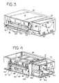
- FIG. 3is a perspective view of the apparatus of FIG. 1 with the front access door open;
- FIG. 4is a perspective view of the apparatus of FIG. 1 with front, top and side panels removed;
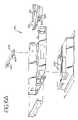
- FIG. 5is a partially exploded view of the apparatus of FIG. 1 ;
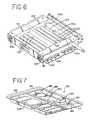
- FIG. 6is a perspective view of a light drawer with a socket panel open
- FIG. 6Ais an exploded view of the light drawer of FIG. 6 .
- FIG. 7is a perspective view of a fluid container carrying tray
- FIG. 8is a perspective view of the fluid carrying drawer with tray removed
- FIG. 8Ais a partial side view of the drawer tilt knob and assembly of the fluid carrying drawer
- FIG. 8Bis a modified partial side view of the drawer tilt knob and assembly of the fluid carrying drawer
- FIG. 9is another perspective view, from the underside, of the fluid carrying drawer without the fluid container carrying tray;
- FIG. 10is a front view of the fluid carrying drawer with fluid carrying tray removed showing side-to-side oscillation of the tray;
- FIG. 11is a perspective view of a container marker assembly
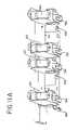
- FIG. 11Ais another perspective view, from the underside, of the container marker assembly
- FIG. 12is an enlarged perspective view of an individual marking unit of the container marker assembly
- FIG. 13is a perspective view of stacked apparatus embodying the present invention.
- FIG. 14is a block diagram of one embodiment of a control system for the apparatus of the present invention.
- FIG. 14Ais a perspective view of a light sensing device which may be used with the apparatus of FIG. 1 ;
- FIG. 15is a plan view of a disposable fluid processing set embodying the present invention.
- FIG. 16is a plan view of another disposable fluid processing set embodying the present invention.
- FIG. 17is a plan view of a disposable fluid processing set embodying the present invention in position for attachment with containers of a collected biological fluid;
- FIG. 18is a perspective view of a part of the disposable fluid processing set embodying the present invention that includes at least one container disposed within a holder;
- FIG. 18Ais a perspective view of an alternative embodiment of the holder in a closed position with containers disposed therein;
- FIG. 18Bis a perspective view of the holder of FIG. 18A in an open position but without container(s);
- FIG. 18Cis a perspective view of another alternative embodiment of a holder in an open position
- FIG. 18Dis a perspective view of another alternative embodiment of a holder with the frame portions separated;
- FIG. 19is a flow chart showing the start-up phase of the control system for the present invention.
- FIG. 20Ais a flow chart showing the pretreatment phase of the control system for the present invention.
- FIG. 20Bis a continuation of the flow chart of FIG. 20A ;
- FIG. 21is a flow chart showing the treatment phase of the control system for the present invention.
- FIG. 21Ais a flow chart showing the steps employed to measure the illumination intensity during the treatment phase of the apparatus of the present invention.
- FIG. 21Bis a flow chart showing the steps employed in calibrating the apparatus of the present invention to measure the illumination intensity in accordance with the present invention
- FIG. 22is a flow chart showing the operator initiated instrument settings functions of the control system for the present invention.
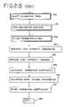
- FIG. 23is a flow chart showing the diagnostic functions of the control system for the present invention.
- FIG. 24is a rear perspective view of one embodiment of the fluid-carrying drawer, fluid container carrying tray and an alternative embodiment of the agitation assembly;
- FIG. 25is a top view of the motor for moving the fluid-carrying drawer
- FIG. 26is an exploded view of the drawer sub-assembly and fluid-carrying tray
- FIG. 27is a perspective view of the fluid carrying drawer with the fluid carrying tray placed therein;
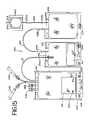
- FIG. 28is a perspective view from the underside, of the fluid carrying drawer without the fluid carrying tray;
- FIG. 29is a perspective view of an radiometer embodying the present invention.
- FIG. 30is a cross-sectional view, taken along section line 30 — 30 of the radiometer shown in FIG. 29 ;
- FIG. 31is an exploded view of the radiometer of FIG. 29 ;
- FIG. 32is a perspective view of the radiometer positioned within a compartment of the fluid container carrying tray
- FIG. 33is a block diagram showing the preferred interconnections and relationships between the printed circuit boards that contain the electronic circuitry for the control system of the present invention.
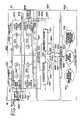
- FIG. 34is a diagram of the lamps and the light sensing circuitry for the light sensing system of the present invention.
- FIG. 35is an electrical schematic diagram of the light sensing circuitry.
- Light box 10An apparatus for treating a biological fluid is generally shown in FIGS. 1–14 and is referred to herein generally as light box 10 .
- Light box 10may be used for treating a variety of materials for a variety of purposes.
- Light box 10is particularly useful in the treatment of biological fluids.
- biological fluidrefers to any fluid that is found in or that may be introduced into the body including, but not limited to, blood and blood products.
- blood productrefers to whole blood or a component of whole blood such as red blood cells, white blood cells, platelets, plasma or a combination of one or more of such components that have been separated from whole blood.
- light box 10is in the treatment of a blood product that has been combined with a photochemical agent for activation when subjected to light.
- photochemical agentsare used, for example, in the inactivation of viruses, bacteria, white blood cells and other contaminants (collectively referred to herein as “pathogens”).
- pathogensviruses, bacteria, white blood cells and other contaminants
- the activated agentinactivates pathogens that may be present in a blood product.
- the biological fluid to be treatedis introduced into a fluid treatment chamber within light box 10 in flexible, plastic, sterilizable, translucent, biologically compatible containers.
- the containersmay be integrally connected to other containers and plastic tubing useful in the processing of the biological fluid both before and after the treatment provided by light box 10 . Examples of the disposable processing set and its components are shown in FIGS. 15–18 . The light box, the disposable processing set and the methods of using them are described in more detail below.
- light box 10includes a housing 12 defined by top panel 14 , bottom panel 16 , front and rear panels 17 , and side panels 18 .
- Housing 12is supported by feet 13 attached to bottom panel 16 ( FIG. 4 ).
- feet 13are rubber or other elastomeric mounts.
- Side panels 18may include handles 22 for grasping and transporting light box 10 .
- An openable or removable door 24 in side panel 18allows for access to the interior of light box 10 and, more specifically, the electronic components of light box 10 , which are described in more detail below.
- Door 24may be opened or removed by turning fasteners 25 .
- light box 10be fairly compact.
- light box 10may be approximately 100–120 cm wide, 20–100 cm deep and between approximately 30–40 cm high.
- a compact instrumentallows, for example, for placement of a greater number of instruments per treatment center and/or may allow two or more instruments to be stacked on top of each other (as shown in FIG. 13 ), resulting in greater throughput of biological fluid per horizontal area or space (i.e. bench space, shelf space or the like).
- Light box 10may include a control module 26 and a fluid treatment module 28 .
- control module 26may include and/or house the command and control elements for the treatment of biological fluid.
- Fluid treatment module 28houses the elements and components where fluid processing takes place.
- Control module 26 and fluid treatment module 28may be contained in the same housing but in a preferred embodiment, as shown in FIG. 2 , they are readily separable modules. Control module 26 and fluid treatment module 28 are electrically and physically connected when light box 10 is in use, but may be separated as shown in FIG. 2 . In one embodiment, control module 26 and fluid treatment module 28 are held together, in part, by a draw pin 30 ( FIG. 4 ), which holds together interfitting parts of the modules. Alternatively, modules 26 and 28 may be held together by captive fasteners 31 (also shown in FIG. 4 ) with or without draw pin 30 . Control module 26 and fluid treatment module 28 may be separated by removing draw pin 30 and/or turning of fasteners 31 shown in FIG. 4 .
- Fasteners 31may be accessed by removing door 24 (shown in FIG. 1 ) in side panel 18 .
- door 24shown in FIG. 1
- other means of connecting and readily separating control and fluid treatment modulesmay be used, including, mating clips and slots on the facing panels of the control 26 and fluid treatment module 28 .
- Providing light box 10 in two readily separable modules 26 and 28allows for easier access to the control and fluid treatment modules 26 and 28 and, generally, provides for easier serviceability of light box 10 . For example, if off-site service is required for control module 26 only, that module can be removed without requiring removal and transport of the entire light box 10 .
- control module 26includes a control panel 32 located in the front of light box 10 .
- Control panel 32includes, a display screen 37 such as, but not limited to, an LCD display for providing graphical, textual and alphanumerical information to the operator regarding the treatment process.
- a key pad 39is included within control panel 32 of control module 26 .
- a different keypad 39 ais shown in FIG. 29 , which is a four-by-four matrix with 10 numerical digits including the ⁇ and # functions, such as the keypads typically provided on telephones. Additional means of data entry are provided by bar code reader scanner 41 which, when not in use, rests in slot 43 or a scanner holder.
- a trough 45may be provided for the coiled cable of bar code reader 41 .
- coiled cable of bar code reader/scanner 41may be routed through the rear of scanner holder 43 .
- Control panelmay also include the on/off switch 35 for light box 10 .
- Control module 26will typically include a programmable microprocessor for operation of light box 10 including central processing unit 27 and memory devices such as random access memory (RAM) and EPROMS for the system program storage and non-volatile memory for back-up data storage.
- Control module 26may further include an isolation transformer 29 for converting an AC input voltage to a DC control system voltage and for maintaining leakage current within acceptable limits for medical devices.
- Other components within control module 26may include power supply 167 , input/output board 33 and a power inlet module 34 , filtered pass through 34 b for use with an external light intensity sensing device and filtered output pass through 34 a.
- Control module 26may be adapted for connection to external components such as a printer 500 ( FIG. 14 ) through parallel and/or serial ports 612 , 613 and/or 616 ( FIG. 33 ) (such as to a label printer through a serial port), or to a computer printed circuit board (PCB) 602 or, for example, to an Ethernet port 621 .
- Computer PCB 602can receive data from the several instruments, allowing the operator at a treatment center to retrieve information regarding the several procedures.
- control module 26may also include other components such as additional printed circuit boards shown in FIG. 33 . While FIG. 14 illustrates one embodiment of an electronic control system to light box 10 , the preferred embodiment is illustrated in FIGS. 33–35 , which are discussed in detail below.
- fluid treatment module 28includes front door 36 which when opened, allows for introduction and removal of the biological fluid into a fluid treatment chamber, as described in more detail below.
- the front panel 17 of fluid treatment module 28may also be opened to allow for fuller access to the interior of fluid treatment module.
- panel 17may include fasteners 17 a and ball detents which, when turned, allow front panel 17 to be opened or removed.
- FIGS. 4 and 5generally show the interior of fluid treatment module 28 with at least top panel 14 and front panel 17 removed.
- fluid treatment module 28includes an interior framework 38 that defines, in part, a fluid treatment chamber 40 and light chambers 42 and 44 for housing light sources (described in more detail below).
- the framework 38may typically be constructed of any sturdy material which will allow light box 10 to support one or more additional light boxes as generally shown in FIG. 13 .
- a preferred materialis aluminum and, in particular, Aluminum 6061 hardened to T-6 or Aluminum 5052/H32.
- light box 10may include a single light chamber, placed in close proximity to fluid treatment chamber or two or more light chambers disposed around a fluid treatment chamber in other than “top and bottom” positions.
- fluid treatment chamber 40is adapted to receive fluid carrying drawer 50 .
- Light chambers 42 and 44are adapted to receive light drawers 60 and 70 .
- Fluid treatment module 28may, optionally, further include a container marker assembly 74 shown, for example, in FIG. 5 .
- Marker assembly 74may carry one or more markers 76 a – 76 d for marking containers, before and/or after treatment, as will be discussed in more detail below.
- fluid carrying drawer 50allows for introduction of biological fluid into fluid treatment chamber 40 .
- Fluid carrying drawer 50may be moveable, either manually or automatically, into and out of fluid treatment chamber 40 .
- drawer 40may include handle 80 .
- movement of fluid carrying drawer 50is facilitated by slides 82 on either or both sides of drawer 50 , which are disposed within rails 86 of framework 38 , as best seen in FIGS. 8 , 9 and 13 .
- fluid carrying drawer 50may include rollers or other devices that allow for movement of drawer 50 into and out of fluid treatment chamber 40 .
- fluid carrying drawer 50preferably includes a pivot mount that permits the drawer to be tilted downwardly when fully withdrawn.
- the ability to tilt drawer 50 downwardlymay be particularly useful for loading containers of fluid in the upper light boxes where two or more light boxes are stacked on top of each other, as shown in FIG. 13 .
- fluid carrying drawer 50may be hingedly attached to framework 38 so that when fluid carrying drawer 50 is fully opened and is outside of housing 12 , front edge of drawer 50 may be tilted downwardly at, for example, a 20–45° angle, and preferably a 30° angle.
- light box 10may include spring loaded tilt knob 83 which, when pulled, releases fluid carrying drawer 50 and allows it to be tilted in the manner described above. More specifically, as shown in FIG. 8A , tilt knob 83 is connected to rod 82 a which is attached to slide 82 ( FIG. 9 ). The end of rod 82 a is coupled to pivot member 83 a, which is connected to ring 83 b attached to drawer 50 . Rod 82 a further includes a spring 82 c and spring stops 82 d. When the end of rod 82 a is coupled to pivot member 83 a, movement of ring 83 b is prevented (as shown in FIG. 8A ).
- knob 83when knob 83 is pulled, (as shown in FIG. 8B ) rod 82 a is uncoupled from pivot member 83 a, allowing ring to rotate relative to pivot member 83 a and, thereby, allowing drawer 50 to be tilted downwardly, as shown in FIG. 13 .
- light box 10 and more specifically, fluid-carrying drawer 50may include release button 300 which, when pressed, allows drawer 50 to be downwardly tilted in the manner shown in FIGS. 26–28 .
- button 300actuates rod 302 , which is attached to bell crank 304 .
- bell crank 304pivots around cylinder 306 .
- the pivoting of bell crank 304pulls rod 308 , thereby disengaging latch pawl 310 from its fixed position on the internal framework of light box 10 (not shown).
- latch pawl 310disengaged, fluid-carrying drawer 50 may be tilted downwardly for ease of loading of the biological fluid containers as generally shown in FIG. 13 .
- fluid carrying drawer 50is generally open and includes a central cavity 88 to allow for placement of a container-carrying tray 90 shown in FIG. 7 .
- Container carrying tray 90may be integral with fluid carrying drawer 50 , although, a removable non-integrated tray 90 may be preferable for easier container loading and/or tray cleaning.
- fluid carrying drawer 50be continuously or periodically agitated to provide mixing of the biological fluid and ensure that substantially all of the biological fluid is sufficiently and uniformly exposed to light and/or any photochemical agent. Accordingly, fluid carrying drawer 50 may be attached to means for agitating the biological fluid.
- fluid carrying drawer 50may include an agitation assembly that, for example, provides side-to side oscillation of tray 90 .
- Agitation assemblymay include a pair of fixed lower rails 95 b that extend front to back within light chamber.
- Upper rails 95 aare attached to the lower rails by pivotally attached link arms 93 a and 93 b. The link arms allow side-to-side motion of the upper rails 95 a.
- an electrical motor 92is attached to lower rail 95 b.
- Motor 92rotates a cam 97 a.
- Cam 97 amay be an L-shaped crank or bracket attached to roller 97 .
- Roller 97is captured between parallel walls 97 b depending from upper rail 95 a. As crank 97 a causes roller 97 to orbit around the motor 92 axis, roller slides fore and aft and up and down between walls 97 b, imparting side-to-side motion of upper rail 95 a.
- the agitation assemblymay include I-shaped legs 320 .
- the bottom flared portions of legs 320are affixed to lower rods 322 which are, in turn, affixed to the floor of the fluid treatment module 26 .
- the top flared portions of legs 320are fixed to plate 324 , which receives fluid-carrying drawer 50 (and tray 90 ), as shown in FIG. 24 .
- Yoke 326is fixed to and depends from one side of plate 324 .
- Yoke 326includes a gap 328 that receives roller 330 of motor 334 .
- motor 334includes a central shaft 336 , which receives a cam 338 .
- Cam 338may be an L-shaped crank or bracket.
- Shaft 340 of cam 338receives roller 330 .
- roller 330is offset from shaft 336 by a predetermined distance.
- roller 330slides fore and aft and up and down and moves yoke 326 accordingly, resulting in side-to-side movement of fluid-carrying tray 90 .
- roller 330is offset from shaft 336 by a distance of anywhere between 0.5 and 1 inch and, more preferably, 0.75 inches. This results in a total displacement of fluid-carrying tray 90 of approximately 1.5 inches.
- Light box 10may include one or more light sources, preferably disposed above and below fluid treatment chamber 50 .
- the light source(s)be readily accessible.
- “readily accessible”means that access to the light source can be quickly and easily had without the use of, for example, a screwdriver or other tools.
- the light sourceit may be desirable that the light source be either partially or completely removable from the housing 12 and/or fluid treatment module 28 .
- the light source(s)may be accessible through any one of the front, side, top or bottom panels.
- the light sourcesare housed in light drawers 60 and 70 . As shown in FIG.
- Light drawers 60 and 70may include slides 99 ( FIG. 6 ) attached to the bottom surface of drawers 60 and 70 . Slides 99 rest and move on brackets 96 and slide mounting blocks 98 of framework 38 as shown in FIG. 5 . Light drawers 60 and 70 may also include handles 84 for grasping during insertion and removal.
- light drawer 60 and/or 70may be divided into two or more chambers 101 and 103 separated by dividing wall 102 .
- Dividing wall 102minimizes light from one light chamber of radiating into the other light chamber. This ensures that the light emitted from each lamp or lamp array and contacting the biological fluid is substantially constant.
- each of the lamp arrays within light chambers 101 and 103may be independently monitored and controlled from control module 26 . Thus, when one array of lamps is turned off, the other array of lamps may remain on. As described in more detail below, this may be particularly useful where two or more containers of biological fluid requiring different levels of treatment are being treated.
- Each of light chambers 101 and 103 of light drawer 60 or 70is generally defined by four sidewalls 105 a–d and a bottom wall 107 .
- Walls 105 a–d and 107may be made of or coated with a reflective material to maximize the amount of light delivered to the biological fluid.
- the light sourceprovides light in the ultraviolet A (UVA) range
- walls 105 a–d and 107may be made of a highly reflective aluminum to provide substantial reflection of UVA light.
- a materialis sold under the name 1500 G-2 and is available from ALANOD of Ennepetal, Germany.
- the light sources suitable for use in the present inventionmay include any light source that is capable of providing light of a particular wavelength and intensity for treating a particular biological fluid.
- light sources capable of providing white light, red light, infrared, ultraviolet A and/or B lightmay be used.
- Light drawers 60 and 70may include a single lamp or an array of multiple lamps 100 .
- light sourcemay include standard fluorescent lamps or bulbs capable of providing light of a wavelength in the UVA (ultraviolet A) range. Such lamps may be obtained from Sankyo Denki of Japan under the product code BL352.
- Light drawers 60 and 70may further, optionally, include fans 109 for cooling lamps 100 and, more specifically, ends of lamps 100 at or near the lamp filaments.
- Socket panelmay also serve as a printed circuit board. Socket panel 106 may be hinged and openable to allow for easy access to lamps 100 , easy insertion and removal of lamps 100 , and in general, easier serviceability of light drawers 60 and 70 .
- a portion of fluid treatment chamber 40 and, for that matter, fluid carrying drawer 50are separated from light drawers 60 and 70 by glass plates 110 .
- upper glass plate 110rests on framework 38 and is, generally, held in place by clamps 112 and 114 .
- a lower glass plate 110 separating a portion of fluid carrying drawer 50 from lower light drawer 70may also be included.
- Glass plates 110are substantially translucent to light of the wavelengths used for the treatment of biological fluid. Preferably, glass plates 110 may also filter unwanted light. Alternatively, a separate filter may be provided for placement between the light source and the fluid treatment chamber 40 .
- glass plate 110may be substantially translucent to ultraviolet light within the range to 320–400 nm, but not translucent to light of a wavelength of less than about 320 nm.
- Such glass platesare commercially available from Schott Glass of Yonkers, N.Y. under the product designation B-270.
- fluid treatment module 28may optionally further include marker assembly 74 .
- Marker assembly 74may include one or more markers 76 a – 76 d for marking containers within fluid treatment chamber.
- One or more markers 76may be provided to mark containers at different stages of the treatment.
- Markers 76 a–dmay be punches for punching holes into a portion of the container such as the container flap as described in U.S. Pat. No. 5,557,098, which is incorporated by reference.
- markersmay be stampers for stamping designated portions of a container with ink.
- Such markersare commercially available from Trodat of Wels, Austria under the product name Printy 4911.
- marker assembly 74may include a plurality of markers 76 a–d for marking a plurality of containers during different stages of the light treatment. Markers 76 a–d may be attached to a bracket 78 , which includes a slide 114 . Slide 114 is suspended from and movable within track 116 which is attached to the interior framework 38 of light box 10 . Thus the entire assembly 74 can be withdrawn from fluid treatment module 28 for reinking, replacement of markers 76 or for general servicing as shown in FIG. 5 .
- each individual marker unitincludes a marker drive motor 120 that moves markers 76 up and down through gear 122 , gear 124 , lead screw 128 , lead nut 126 , bracket 130 and spring 132 . Movement of gears 122 and 124 actuates movement of lead screw 128 and causes downward and/or upward movement of lead nut 126 , bracket 130 and consequently marker 76 .
- Fluid treatment module 28includes blower 134 which provides air flow into fluid treatment chamber 40 and fluid containers and thus, provides for temperature control of fluid treatment chamber 40 ( FIG. 5 ).
- Blower 134receives ambient air through an opening in bottom wall 16 located below blower 134 .
- Blower 134may be provided with a filter to prevent dust from entering fluid treatment module 26 .
- air from blower 134may also pass through opening 136 of fluid treatment module 28 and a perforation or opening 136 a in control module 26 , as seen, for example in FIGS. 2 and 4 .
- fluid treatment module 26may be provided with an air flow sensor for monitoring air movement. As shown in FIG.
- sensor 135may be located at blower 134 or in close proximity thereto in fluid treatment module 26 .
- a temperature sensor 135 disposed in light box 10senses the ambient temperature. Thus, if the ambient temperature rises above a predetermined threshold temperature, such as may occur if blower 134 fails, the treatment procedure will be terminated and the container of biological fluids will be marked or identified as unusable.
- fluid carrying drawer 50may include a tray 90 for holding one or more containers of biological fluid.
- Tray 90shown in FIG. 7 , may be placed within the cavity 88 of the fluid carrying drawer 50 ( FIG. 8 ).
- tray 90may be made of a molded plastic material. Where the biological fluid is treated from two sides, the molded plastic material should be sufficiently translucent to the light provided by the lamps 100 .
- Suitable materials for tray 90include acrylic polymers such as polymethyl methacrylate (PMMA) or members of the polyolefin family such as methylpentene copolymer. Such materials are available from many sources including CYRO Industries of Rockaway, N.J. under the product name ACRYLITE® OP 4 or from Mitsui Plastics of White Plains, N.Y. under the name TPX.
- tray 90may be divided into a first portion 180 and a second portion 182 separated by dividing wall 184 . As shown in FIG. 27 , at least a portion of dividing wall 184 may be made of or covered with a reflective material of the type described above. In a preferred embodiment, the portion of dividing wall that separates first compartments 188 (described below) is reflective. A reflective divider provides improved and more uniform distribution of light to the fluid containers. As shown in FIG. 7 , tray 90 may include retaining tabs 186 for placing a slit or other aperture of a biological fluid container 206 over tab 186 to limit movement of the container within tray 90 and ensure that the container is substantially within the field of light provided by the light source. The volume of tray 90 should be sufficient to hold at least the entire volume of biological fluid contained within the containers so as to minimize the risk that, in the event of container leakage, liquid will overflow and contact the electrical and mechanical components of light box 10 , even during agitation.
- tray 90may be compartmentalized to provide separate compartments for the container undergoing treatment on the one hand, and the remainder or a portion of the remainder of the disposable processing set, on the other hand.
- first portion 180 and second portion 182each include a first compartment 188 and second compartment 190 separated by discontinuous wall 192 .
- First compartment 188may hold a container of biological fluid 206 and the second compartment may hold the remaining components of the fluid processing set.
- a slot in the wall 192accommodates the tubing that connects container 206 with the remainder of the disposable processing set. The slot may also assist in limiting movement of container 206 within tray 90 .
- Tray 90 or second compartment 190 of traymay further include container retaining tabs or pegs 193 to hold in place the containers in the second compartment and/or limit movement of such containers within tray 90 .
- pegs 193may be located on drawer 50 , as shown in FIG. 26 .
- container 206 within a first compartment 188is positioned substantially within the field of light provided by the light source.
- the remainder of the disposable processing set and/or containers within a second compartment 190are outside the field light, preferably held in place by tray cover 380 , described below.
- containers within second compartment 190are aligned substantially with marker assembly 74 as shown in FIGS. 4 and 5 .
- the status of the treatmentmay be indicated on the other containers of the processing set within the second compartment 190 by markers 76 a–d.
- drawer 50may include a cover 380 of the type shown in FIGS. 26–28 .
- Cover 380holds in place containers within second compartment 190 .
- cover 380may be hingedly attached to drawer 50 and flipped over compartments 190 prior to the illumination process.
- cover 380may include latch 382 for securing cover 380 to dividing wall 184 of tray 90 .
- Cover 380may also include a plurality of apertures 384 aligned with bag placement sensors (described below).
- Cover 380can be made of any suitable material which is not translucent to light from light sources.
- cover 380is made of aluminum.
- Light box 10may include sensors for detecting different conditions during the pretreatment and treatment processes.
- the sensorsrelay signals to the microprocessor of the light box 10 that is housed within control module 26 .
- sensorse.g., 404 , 430
- the computeralerts the operator, either by an audible alarm or a message on the display screen 37 .
- the operatormay, in response to the alarm or message, take action through keypad 39 .
- the control systemmay be preprogrammed to automatically take action; such as a terminate treatment, if necessary.
- light box 10may include internal light intensity sensors 404 for measuring the intensity of light provided by the lamps 100 to fluid treatment chamber 50 .
- sensors 404send signals through input/output board 33 ( FIG. 14 ) to microprocessor 160 as described above.
- light intensity sensors 404may be located within the light chambers 101 and 103 of light drawers 60 and 70 ( FIG. 6 ).
- light drawer 60 and/or 70include a light intensity sensor subassembly 402 on the underside of drawer 60 and/or 70 .
- subassembly 402includes two or more sensors 404 attached thereon and placed within sensor windows 406 located in the bottom wall 107 of drawers 60 and/or 70 .
- Sensor windows 406allow light from lamps 100 to pass through and contact sensors 404 .
- Sensors 404may include or be used with one or more filters to filter out unwanted light.
- the filters used in association with sensors 404have a maximum sensitivity in the wavelength range that substantially matches the wavelength range within which the particular photochemical agent is most effectively activated (i.e., the “action curve”). This allows sensors 404 to detect the effectiveness of photochemical activation.
- Sensors 404are available, for example, from Micropac Industries, Inc. of Garland, Tex. under part number 61120. Filters are available from a variety of sources such as Schott Technical Glass of Duryea, Pa.
- a fluid carrying drawer sensor 144may be included for monitoring the position of fluid carrying drawer within fluid treatment chamber 40 .
- Fluid carrying drawer positioning sensor 144ensures that the drawer 50 is in a fully closed position and therefore, that containers of biological fluid are substantially within the field of light provided by lamps 100 . If the drawer is not in a fully closed position, sensor 144 sends a signal to the microprocessor, alerting the operator and preventing treatment from proceeding.
- Light box 10may, optionally, further include temperature sensors 145 for either directly or indirectly monitoring and measuring the temperature within fluid treatment chamber 40 .
- Temperature sensormay be disposed within the fluid treatment chamber 40 or, as shown in FIGS. 4 and 5 , may be disposed on the exterior of light box 10 to measure the ambient temperature of the outside environment.
- ambient temperature sensor 145may be located anywhere on the surface of light box 10 .
- ambient temperature sensor 145is placed at or near control module 26 .
- Ambient temperature sensor 145provides an indication of the air temperature being delivered to fluid treatment chamber by blower 134 .
- the ambient temperature sensorsends a signal to the microprocessor as generally described above, which alerts the operator that the temperature is approaching or has exceeded its limit. Accordingly, the operator and/or instrument may take further action.
- sensor 430may be attached to marker subassembly 74 , as shown in FIG. 11A , and measures movement of the agitation assembly described above.
- sensor 430may be attached to marker subassembly 74
- sensor 430may include an infrared source such as, but not limited to a light emitting diode (LED) or laser that contacts a selected reflective portion of the agitation assembly. If sensor 430 does not detect reflection or does not detect reflection at the predetermined frequency, it signals the microprocessor accordingly.
- LEDlight emitting diode
- FIG. 27A preferred embodiment of a motion sensor arrangement for the agitator system is illustrated in FIG. 27 .
- This agitator motion sensorincludes a light emitter 386 , such as a lamp, a light emitting diode, a laser diode, or the like, disposed on one side of tray 90 .
- An aperture 388is defined through one edge of cover 380 and a light detector 385 , such as a photo-diode, photo-transistor, photo-multiplier tube, or the like, is disposed on the opposite side of cover 380 from the light emitter 386 .
- a brief electronic pulsewill be generated by light detector 385 when light is transmitted through aperture 388 to light detector 385 . Based upon the rate of pulses, the speed of agitation can be determined or confirmed. Also, if no pulses are received, it can be assumed that the agitator system is not in motion.
- Light box 10may also include a sensor 440 to detect whether the front door of the light box is closed during treatment.
- Door sensormay be a magnetic switch that detects contact between door 36 and magnetic plate 441 shown in FIG. 3 .
- plunger switch 36 aFIG. 4
- light box 10may include a door lock 388 .
- Door lock 388may include a solenoid that establishes contact with a pin on door 36 and ensures that door 36 remains locked during treatment.
- Light box 10may also include sensors 450 for determining whether containers are in position for marking by markers 76 .
- sensors 450may be attached to markers 76 and may include optical receivers aligned with light emitting diodes (LED) (not shown) typically located below fluid carrying tray 90 .
- LEDlight emitting diodes
- the labels of containers placed within the second compartment 190 of tray 90 or a holder or organizer used to hold together containers in compartment 190prevent optical receiver 450 from receiving the LED signal, indicating the presence of a container.
- each marker 76 a–dmay include a microswitch (shown as 470 in FIG. 14 ) to detect whether movement of the marker has occurred and to prevent mechanical failure or damage to the parts that make up the marker.
- a pair of light emitters 383 and 384may be disposed on one side of an edge of cover 380 .
- a pair of light detectors 381 and 382may be disposed on an opposite side of the edge of cover 380 .
- a pair of apertures 387 and 389is defined through the edge of tray 90 .
- a computer printed circuit board (PCB) 602preferably includes a 486 DX 4 compatible central processing unit (CPU), or microprocessor, 603 typically operating at 100 MHz, or more, to provide, and to service, a multiplicity of functions.
- a DRAM module 604provides memory for CPU 603 , which may be, by way of example, about 32 Megabytes. Flash memory may be added to a compact flash socket 605 . Preferably, about 32 Megabytes of flash memory is provided.
- VGA BIOS 606is programmable to support displays on display screen 37 on control panel 32 ( FIGS. 1 and 2 ).
- a VGA port 607provides video information to display screen 37 on control panel 32 via output lines 608 .
- a PC/ 104 portprovides an ISA Bus 610 for transferring information to and from computer PCB 602 .
- RS232 compatible ports 612 through 615provide serial information transfer, such as from bar code reader 41 .
- One of the RS232 portsis configurable as an RS 485 port, if desired.
- Port 615is at the rear panel of the light box 10 , and ports 612 and 613 are spares.
- one of spare ports 612 or 613may be used for a label printer.
- a printer port 618 on computer PCB 602is brought out to the back panel of light box 10 as a port 619 for connection to a printer.
- an Ethernet port 620 on computer PCB 602is provided as an Ethernet port 621 on the back panel.
- Computer PCB 602is preferably an off-the-shelf computer board, such as that commercially available from Ampro Computers, Inc., San Jose, Calif. under part number LB3-486e. More information about this and comparable computer PCBs is available at internet site www.ampro.com, which is incorporated herein in by reference in its entirety.
- An interface PCB 606directly or indirectly interfaces computer PCB 602 with most of the other electrical apparatus, such as lamps, sensors, displays and so forth. Interface PCB 606 is subdivided into several portions.
- An LCD portion 624receives video and control signals from computer PCB via lines 608 and provides control signals to a back light inverter (BLI) PCB 626 to control and to supply power for the backlighting of display panel 37 . LCD portion 624 also supplies video and control signals, and power, via lines 627 to display panel 37 .
- a keypad and LED portion 630receives inputs from keypad 39 at the user interface 32 , and sends such inputs to computer PCB 602 via ISA bus 610 .
- a light sensor portion 634 of interface PCB 606bi-directionally communicates with a relay PCB 640 via a plurality of lines 635 to provide control output signals and to receive sensor input signals.
- a miscellaneous sensors portion 636 and a relay control portion 637bi-directionally communicate with relay PCB 640 via a plurality of lines 638 to provide control output signals and to receive sensor input signals.
- Interface PCB 606also supplies operating power to the other PCBs.
- Interface PCB 606receives +5 Vdc and +12 Vdc at a connector 622 and +24 Vdc at a connector 623 , all from a power supply 167 .
- Relay PCB 640is supplied with +5 Vdc and +24 Vdc on certain of lines 638
- front panel user interface 37is supplied with +5 Vdc on one of lines 627
- BLI PCB 626is supplied with +5 Vdc on one of lines 625
- computer PCBis supplied with +5 Vdc and +12 Vdc on certain of lines 610 , all from interface PCB 606 .
- relay PCB 640directly receives 240 Vac from the power supply 167 at a connector 641 to supply power to the shaker motor 92 .
- Relay PCB 640controls the application of power to upper lamp ballasts 645 and lower lamp ballasts 646 , such as with electronic relays located on relay PCB 640 , to supply operating power to upper lamps 100 and to lower lamps 100 under the influence of control signals from light sensor interface 634 on interface PCB 606 .
- Light sensor circuitry shown in FIG. 34is disposed on upper and lower light sensor PCBs 643 and 644 and provides signals to relay PCB 640 that are indicative of the intensity of illumination provided by the upper and lower lamps, respectively.
- Relay PCB 640also controls the application of power to shaker motor 647 and blower fan 648 , such as with electronic relays, in accordance with control signals from relay control interface 637 on interface PCB 606 .
- Relay PCB 640routes signals from door solenoid 648 and miscellaneous sensors 649 to miscellaneous sensors interface 636 on interface PCB 606 .
- light box 10has two light chambers 42 and 43 for treating biological fluids in either or both chambers.
- Two light arraysconsisting of four lamps 100 are disposed in an upper position and in a lower position in each chamber for a total of 16 lamps, as seen in FIG. 34 .
- a light sensing systemfor sensing the intensity of the illumination from lamps 100 , is generally designated 650 .
- Disposed adjacently to the upper lamp arrays in chambers 42 and 43is upper light sensor PCB 643 .
- Lower light sensor PCB 644is similarly adjacently disposed to lower light arrays.
- Light sensors 404are positioned on upper and lower light sensor PCBs 643 and 644 , respectively, between pairs of lamps 100 such that each sensor monitors the illumination level of two adjacent lamps.
- each light sensoris preferably located midway between a pair of monitored lamps 100 .
- Light sensors 404provide a frequency output generally in the range of 10 Hz to 1 MHz depending upon the sensed irradiation level. In this application, sensors 404 preferably operate near a mid-range, such as in about the 1 KHz to 100 KHz range, for example.
- the frequency outputs from upper light sensors 404are sent to a pair of multiplexers 651 and 652 .
- Multiplexer 652is a secondary or redundant multiplexer that is used to confirm that data received from multiplexer 651 is accurate.
- a test circuit 654consists of an oscillator 655 that has its frequency divided by a divider 656 to provide three test or reference frequencies on three lines 657 , which are provided as inputs to multiplexers 651 and 652 .
- these test frequenciesmay be about 230 KHz, 115 KHz and 57.5 KHz.
- the power supply +5 Vdcis also provided as an input to multiplexers 651 and 652 to monitor the power supply for any undesired noise that could interfere with the signals from the light sensors.
- Three address selection lines 658including A 0 , A 1 and A 2 , are used to cause multiplexers 651 or 652 to alternately sample one of the outputs from the four light sensors, one of the three test frequencies or the power supply voltage. For example, the sampling periods may be about 15 milliseconds.
- These address selection bits on lines 658are generated by a programmable logic device (PLD) 680 on interface PCB 606 and supplied to upper light sensor PCB by lines 669 and to lower light sensor PCB by lines 668 .
- Lower light sensors 404 , multiplexers 660 and 661 and test circuit 662 on lower light sensor PCB 644operate similarly to the corresponding elements described on upper light sensor PCB 643 to provide a second multiplexed frequency signal.
- PLDprogrammable logic device
- the outputs of multiplexers 652 and 660are routed to a frequency counter 670 on interface PCB 606 via lines 665 and 664 .
- the outputs of multiplexers 651 and 661are routed to frequency counter 671 also on interface PCB 606 via lines 667 and 666 .
- Counters 670 and 671are commercially available from Intel Corporation, Santa Clara, Calif. under part number 8254.
- PLD 680selects data from frequency counter 670 by a chip selection line 681 or from frequency counter 671 by a chip selection line 682 .
- Frequency counters 670 and 671 and PLD 680share a common data bus 683 for the transfer of data therebetween.
- PLD 680thus receives counts from counters 670 and 671 that represent the frequencies received by these counters from multiplexers 651 , 652 , 660 and 661 which, in turn, represent the illumination levels from all 16 of the lamps 100 in light box 10 .
- PLD 680provides this lamp illumination data to computer PCB 602 on data busses 687 and 688 .
- PLD 680essentially acts as a conduit for the count information from counters 670 and 671 to computer PCB 602 , provides buffering of these count signals and provides chip select functions to select counter 670 or 671 .
- Counters 670 and 671can issue interrupt requests to PLD 680 on lines 684 and 685 , respectively.
- PLD 680can also issue interrupt requests to computer PCB 602 on a line 686 and control signals are received by PLD 680 from computer PCB 602 on one or more lines 689 .
- PLD 680is commercially available, for example, from Altera Corporation of San Jose, Calif. under part number EPM7128S.
- Sensor read software 690enables CPU 603 on computer PCB 602 to read the data sent from PLD 680 on data busses 687 and 688 .
- Independent illumination software 691monitors the data for any malfunction or irregularity. For example, if the illumination data from any light sensor 404 is below a defined threshold level, one of the lamps 100 may have failed or is providing insufficient illumination. In this instance, a message will be displayed on display 37 to replace one or more lamps 100 .
- Energy measurement software 692measures the illumination level supplied by lamps 100 , as by analyzing the frequency counts from PLD 480 , and then essentially integrating the measured illumination level over time until the predetermined illumination dose for the biological fluid being treated in light box 10 is reached.
- Software 692may recalculate the light intensities about every second, for example. Frequent recalculations are preferred because the light intensity from lamps 100 changes with temperature. Based upon these continuous recalculations of light intensity, energy measurement software 692 also determines the current illumination dose that the biological fluid has been subjected to since the initiation of treatment.
- Software 692is essentially integrating the light intensity in real time to determine the current illumination dose. Software 692 can similarly estimate how much additional time is required, based upon currently measured light intensities, to reach the desired illumination dose.
- software 692Upon reaching the dosage entered by the user at the beginning of treatment, software 692 causes illumination to cease and the user is advised that treatment is completed.
- Software 692also preferably constantly monitors the count of the test frequencies 657 because these frequencies are known and the count results will confirm the signal paths and counting accuracy with respect to the frequency signals from light sensors 404 .
- the redundant light sensing channel provided by secondary multiplexers 652 and 661are also preferably monitored to confirm the accuracy of information received from primary multiplexers 651 and 660 . If the frequency count data received from primary multiplexers 651 and 660 are not within a certain tolerance with the data received from secondary multiplexers 652 and 661 , an error message will be supplied to the user, as on display 37 .
- energy measurement software 692terminates illumination in light box 10 .
- Radiometer 460may be provided to verify light intensity provided by light box 10 and for calibration of light box 10 .
- Radiometer 460may be adapted for placement within fluid treatment chamber 40 for measuring the energy dose delivered to the biological fluid. More specifically, radiometer 460 may be adapted for placement within the fluid container carrying tray 90 . In one embodiment, radiometer 460 may be adapted for placement within a compartment of tray 90 such as first compartment 188 of tray 90 .
- radiometer 460may include a support 465 having a top surface 467 and a bottom surface 468 .
- Support 465is typically a printed circuit board.
- One or more sensors 469are electrically and physically connected to support 465 .
- support 465also includes data port 512 .
- radiometer 460may include a plurality of sensors 469 spaced across the top and/or bottom surface(s) to receive light from different points on one or more lamps. Also, sensors 469 may be placed on one side of support 465 , but preferably are placed on both the top surface 467 and the bottom surface 468 . Top and bottom placement of sensors 469 is particularly preferred where radiometer 460 is used to measure light provided by two facing light sources, such as the two arrays of lamps 100 in one of the embodiments of light box 10 .
- Radiometer 460is preferably calibrated with a precision light source in accordance with NIST standards.
- a bar code 506may be placed on the edge of one of the halves 504 .
- Bar code 506preferably contains information on the identity of each radiometer, such as a unique identifying number or a serial number.
- the calibration coefficients determined during the most recent calibration of radiometer 460 for each of the sensors 469are also preferably included in bar code 506 , and an expiration date by which radiometer 460 will need to be recalibrated. For example, the expiration date may be one year from the date of the most recent calibration.
- reading of bar code 506 by bar code reader 41will provide CPU 603 with information on the identity of radiometer 460 , the calibration coefficients associated with that particular radiometer, and the date by which radiometer 460 needs to be recalibrated.
- Support 465is preferably housed in cover 501 .
- cover 501may be made of two halves 503 and 504 that are attached together.
- Cover 501may include a label 506 ( FIG. 29 ) displaying a unique bar code for each radiometer 460 .
- radiometeralso includes intermediate panels or substrates 508 and 510 .
- Cover halves 503 and 504 and substrates 508 and 510may be made of any hard, commercially available molded plastic.
- a preferred materialis a terpolymer of acrylonitrile, butyldiene and styrene (ABS). Slots in cover 501 and substrates 508 and 510 are provided to accommodate sensors 469 .
- ABSterpolymer of acrylonitrile, butyldiene and styrene
- a connector cable 516is attached to radiometer 460 for electrical connection to light box 10 and, for example, to port 461 ( FIG. 5 ).
- Thisallows radiometer 460 to transmit data to the computer PCB 602 ( FIG. 33 ) of light box 10 , which system provides information to the operator and/or automatically takes action based on the transmitted data.
- Radiometer 460may also include a slit 472 ( FIG. 29 ) for placement over tab 186 ( FIG. 7 ) in tray 90 of light box 10 .
- Sensors 469are generally any device that is capable of detecting light of selected wavelengths. These sensors are preferably robust such that they reproducibly detect the appropriate wavelengths accurately.
- these sensorsmay comprise a plurality of optical fibers that absorb the selected wavelengths and channel the light into an appropriate detector. Such optical fibers can be configured to appropriate dimensions to represent the dimensions over which the light delivery is to be measured. An advantage of this configuration is that the optical fibers can cover a large percentage of the area over which the light delivery is to be measured.
- sensors 469 in radiometer 460are preferably the same type of sensor as sensors 404 in light sensing system 650 . Of courses, sensors 404 and 469 need to be capable of detecting light of the desired wavelengths. Sensors 469 may also include or be used with filters to filter out unwanted light as substantially described above.
- radiometer 460When used in connection with light box 10 , it is preferred that the dimensions and geometry of radiometer 460 be substantially equivalent to the dimensions of the fluid-filled containers used with light box 10 . Accordingly, it is preferred that the light sensing area of radiometer 460 have a height, a width and a thickness substantially equal to such filled containers. A radiometer with dimensions substantially equal to the fluid-filled container provides a reliable approximation of the energy being delivered to the fluid and of the effectiveness of the treatment.
- radiometer 460may be used for light intensity verification by, for example, the operator and for calibration of light box 10 generally and more specifically, of internal light sensors 404 .
- the operatormay place radiometer 460 in first compartment 188 of tray 90 , as shown in FIG. 32 .
- Connector cable 516may be pressed into strain relief tabs 474 within light box 10 ( FIG. 8 ) or, more preferably, thread through slot 390 in drawer 50 , as shown in FIG. 32 .
- the fluid carrying drawer 50is inserted into fluid treatment chamber 40 and door 36 is closed. Lamps 100 are turned on and the light delivered is measured by sensors 469 in radiometer 460 .
- the light measured by sensors 469is processed by the system's microprocessor 603 on computer PCB 602 to provide a calibrated reading of the energy being provided to the fluid treatment chamber 40 .
- microprocessor 603may use the calibrated readings of the light levels from each sensor 649 of radiometer 460 to calculate a calibration coefficient for light levels sensed by each sensor 404 on upper and lower light sensor PCBs 643 and 644 .
- energy measurement software 692FIG. 34
- the flow chart in FIG. 21Aalso provides information about the processes of determining the light intensity and determining the treatment time.
- the operatorcan monitor the output of lamps 100 and determine any diminishment in the lamp output by comparing the reading to a pre-set acceptable energy dose range.
- the readings provided by sensors 469are also compared to the readings provided by sensors 404 to detect any diminished sensing capability of sensors 404 .
- the processmay be repeated with the other first compartment 188 .
- the energy dose measured by radiometer 460is substantially equal to the energy dose detected by sensors 404 , but is outside the pre-set dose range, this may be an indication that the output of lamps 100 has diminished and that lamps 100 may have to be replaced.
- the energy dose as measured by radiometer 460is substantially equal to the expected pre-set dose of the instrument, but both are different from the energy dose as measured by sensors 404 , this may be an indication that sensing capability of sensors 404 has diminished.
- the dose as measured by sensors 404is substantially equal to the expected pre-set dose, but different than the energy dose as measured by radiometer 460 , this may indicate that the sensing capability of radiometer 460 has diminished.
- Radiometer 460may also be used to calibrate light box 10 .
- Radiometer 460itself may be calibrated against a standard (e.g. a standard from the National Institute for Standards and Technology or NIST), or by using an independent calibration system that has been calibrated to NIST standards.
- a standarde.g. a standard from the National Institute for Standards and Technology or NIST
- radiometer 460may have utility in other applications and is not limited to use in the apparatus or methods of the present invention. Indeed, radiometer 460 may be used whenever light is to be measured over an extended surface area or from opposite directions. Radiometer 460 also has utility where it is desired to average light intensity measurements over a surface area, including non-planar surfaces. It will be readily appreciated that radiometer 460 could be configured with complex, non-planar surfaces, if so desired.
- the components of the fluid treatment module 28 including the agitator assembly, the light sources, the blower, the marker subassemblyare powered by power supplies in an alternative embodiment of the electronic control system shown in FIG. 14 .
- the letter “n”represents the number of electrical or mechanical components such as sensors, lamps, ballasts etc.
- power supplies (ballasts) 166power lamps 100 and are controlled by relay board and isolation transformer 29 .
- Shaker motor 92is powered through relay board and isolation transformer 29 .
- Additional power supply 168supplies power for the blower 134 , light drawer fans 109 , and drive motors 120 for markers 76 a–d and door lock 480 .
- the power supply for powering these componentsmay be approximately 24 volts DC.
- Power supply for powering shaker motormay be 230V AC.
- Power supply 167may supply +5 and +12 volts DC to, for example, computer board 160 .
- light box 10includes a programmable computer software-based control system 600 to control the operation of light box 10 that has already been described with reference to FIGS. 33–35 .
- the control system 600is further generally and diagrammatically depicted in FIGS. 19–23 and is described in greater detail in connection with the description of the method of processing and treating a biological fluid which follows the description of the disposable processing set provided below.
- Disposable processing sets useful with light box 10are shown in FIGS. 15–18 .
- the disposable processing setwill include two or more plastic containers integrally connected by plastic tubing. At least one of the containers should be suitable for holding the biological fluid during light treatment. The other container should be suitable for storage of the biological fluid after treatment.
- the disposable processing setmay be joined with containers of biological fluid, and the fluid may be transferred to containers of the disposable processing set. Further details about these disposable processing sets are described in the U.S. Patent Application entitled “Fluid Processing Sets and Organizers for the Same,” bearing Ser. No. 10/269,444, filed Oct. 11, 2002, and incorporated herein by reference, in it entirety.
- Processing set 200includes a container 202 , a container 206 , a container 210 and a container 214 .
- the containersmay be integrally interconnected with tubing segments as generally shown and described in detail below.
- the sizes and internal volumes of containers 202 , 206 , 210 and 214may vary depending on the biological fluid being processed.
- container 202may be capable of holding approximately 5–30 ml of fluid
- containers 206 and 210approximately 1000 ml
- container 214between approximately 1000–1500 ml.
- other desirable sizes and volumesmay be used and are within the scope of the present invention.
- container 202may include, for example, a photochemical agent which is mixed with the biological fluid.
- photochemical agentsinclude psoralen compounds described in U.S. Pat. No. 5,709,991 and compounds from the family of phenothiazine dyes such as, but not limited to, methylene blue and riboflavin.
- Container 202may be made of any material suitable for holding such photochemical agents.
- One such materialmay be a blend of ethylene polypropylene, polyamide and a block copolymer of ethylene and butylene with terminal blocks of polystyrene. Containers made of such material are available from Baxter Healthcare Corporation under the name PL2411.
- Container 202includes a tubing segment 203 extending therefrom and having a sealed end 204 .
- a second tubing 205 extending from container 202is integrally connected to container 206 .
- the photochemical agentmay be contained or predisposed within container 206 , thereby eliminating the need for a separate container 202 for holding the photochemical agent.
- the photochemical agentmay be combined with the biological fluid prior to joinder to the disposable processing set.
- the photochemical agentmay be included in a container 201 used to hold the biological fluid collected from a donor ( FIG. 17 ).
- Container 206is preferably a container suitable for holding the biological fluid during light treatment. Accordingly, it is desirable that container 206 be made of a clear, durable, thermoplastic material that is translucent to light of the selected wavelength and sterilizable by known forms of sterilization including steam sterilization, gamma and electron beam radiation.
- containeris made of a material that is substantially translucent to UVA light and remains stable after sterilization.
- materialsmay include polyvinyl chloride, but more preferably, may be blends of thermoplastic polymers and copolymers, including general purpose polymers, elastomers and the like.
- One such materialincludes the block copolymer described above which includes a central block of ethylene and butylene and terminal blocks of polystyrene.
- Block copolymers of the type described aboveare available from the Shell Chemical Company under the name KRATON.
- the block copolymermay be blended with other polymers such as ultra low-density polyethylene (ULDPE) and ethylene vinyl acetate (EVA).
- ULDPEultra low-density polyethylene
- EVAethylene vinyl acetate
- Containers made of the blended materialare available from Baxter Healthcare Corporation of Deerfield, Ill. under the name PL-2410.
- Other thermoplastic materialsmay also be suitable for container 206 , including materials including KRATON, EVA, and polypropylene.
- a container made from such materialis also available from Baxter Healthcare Corporation under the name PL-732.
- Still other suitable materials for container 206include fluoropolymers such as polytetrafluoroethylene (PTFE), PFA or copolymers including
- Container 206further includes a slit 207 which, as described above, may be placed over retaining tab 186 in tray 90 .
- Container 206includes a tubing segment 208 which may be integrally connected to a container 210 .
- container 210may, for example, include an adsorbent material 211 for removing excess photochemical agent or the byproducts of the photoactivation process.
- the adsorbent materialmay be contained in a semi-permeable pouch, preferably affixed to the container walls or portions thereof within the interior chamber of container 210 .
- the interior chamber of container 210has a volume sufficient to hold the biological fluid from container 206 .
- Such a container and the adsorbent materialare disclosed in more detail in copending patent application entitled “Plastic Containers Having Inner Pouches and Methods for Making Such Containers” which is being filed simultaneously herewith in the names of Mahmood Mohiuddin, George D. Cimino and Derek J. Hei, and is incorporated by reference in its entirety. Materials such as those used in the PL-2410 and PL-732 containers described above are suitable for use in container 210 .
- Container 210may also include a time-sensitive tape 209 . Tape 209 changes color with time, thus informing the operator if the biological fluid has contacted the adsorbent material for a sufficient period of time.
- Container 210may be integrally connected by tubing segment 211 to another container 214 which may be suitable for storage of the biological fluid. As shown in FIG. 15 , the portion of tubing segment 211 that communicates with the interior of container 210 may include a filter 211 a to capture loose particles of adsorbent, if any.
- Container 214may include and/or be capable of receiving a label 216 which may carry bar codes 222 or other indicia that provide information about the biological fluid.
- bar codes 222may identify the donor, the product, the lot number of the biological fluid, expiration date and the like.
- Container 214may include additional bar codes or indicia 224 which are used to provide information regarding the status or progress of the fluid treatment (described in more detail below).
- Container 214may also include a slit 226 and/or apertures 228 , 230 for placement over corresponding pegs ( 193 ) on tray 90 . Materials such as those described above are suitable for use in container 214 .
- Container 214may also include sampling pouches 214 a and access ports 214 b to allow for fluid access during later transfusion, as will be recognized by those of ordinary skill.
- disposable processing setmay include a single container for housing the adsorbent material of container 210 and for storing the biological fluid, thereby combining the functions of container 210 and 214 described above.
- the disposable processing set 200 described hereinmay further include frangible members 230 ( a–c ) disposed within tubing segments as shown in FIG. 15 .
- Frangible members 230are broken at the appropriate time to establish fluid communication between the containers of the processing set 200 .
- frangible connectorsare described in detail in U.S. Pat. No. 4,294,297 which is incorporated by reference herein.
- Tubing segments of disposable processing set 200may further include indicators 234 a and 234 b on the tubing to indicate proper positioning of the disposable processing set within the tray 90 (as will be described more detail below) and/or to serve as indicators of where tubing is to be severed and sealed.
- indicators 234may be plastic rings disposed around tubing segments. Of course, other tubing indicating means may be used.
- disposable processing set 240also includes a container 242 which carries a photochemical agent, a container 244 which holds the biological fluid during light treatment, a container 246 which includes an adsorbent material for removing excess photochemical agent and/or the byproducts of the photoactivation process, and a container 248 suitable for storage of the biological fluid.
- Container 248is adapted to receive label 249 with bar codes or other indicia and may include additional indicia 251 including, for example, additional bar codes as substantially described above.
- container 246is a flow through device which includes adsorbent material 212 but does not include a chamber for holding the biological fluid for any significant period of time.
- Disposable processing set 240may further include an air reservoir 256 and air sink 258 .
- Air reservoir 256provides air to help expel biological fluid from container 244 and air sink 258 receives excess air expelled from storage container 248 after processing.
- Air reservoir 256 and air sink 258may be made of any suitable biocompatible material, including the materials described above.
- the containers of disposable processing set 240may also be made from the materials generally described above.
- container 256is substantially impermeable to air.
- the containers of disposable processing set 240 shown in FIG. 16may be integrally interconnected by tubing segments 243 , 245 and 247 .
- Tubing segmentsmay further include frangible members 249 ( a–c ) for opening fluid communication between the containers.
- Disposable processing set 200(or 240 ) is typically provided to the user in a sealed package in a manner that is easy for the user to unpack and use. For example, upon opening the package, it is preferred that the container to be used first in the fluid processing be located near the top of the package. For example, in the processing set 200 shown in FIG. 15 , container 202 would be located near the top of the package, followed by container 206 , followed by the remainder of the disposable processing set that includes containers 210 and 214 . In addition, if disposable processing set includes container 202 , (or 242 in the embodiment of FIG. 16 ) at least such container should include a separate and additional light impermeable overwrap to protect the contents (i.e. the photochemical agent) from exposure to light which could result in premature activation of the photochemical agent. In one embodiment, the light impermeable overwrap may be permanently sealed to the outer walls of container 202 .
- containers 210 and 214may be contained within or held together by a holder.
- Holdermay be any device such as a clamp that holds together containers 210 and 214 .
- the holdermay be integral with the disposable processing set or may be provided separately.
- holder 260may be a receptacle or other shell-like holding device.
- holder 260may include a bottom wall 262 which separates the containers 210 and 214 from container 206 .
- holder 260may have sidewalls 262 and 264 , a back wall 268 and includes a substantially open front portion as shown in FIGS. 17–18 .
- bottom wall 262may include a slot 263 to accommodate tubing that connects containers of disposable processing set 200 .
- Holder 260may also include additional side openings 265 (shown, for example, in FIG. 17 ) for holding tubing segments of container 202 prior to unpackaging of the disposable processing set.
- Holder 260may be made of any suitable material such as but not limited to plastic or cardboard.
- holder 260is made of a moldable plastic material that may be sterilizable and impact resistant.
- FIGS. 18A–18DAlternative embodiments of holder 260 are shown in FIGS. 18A–18D .
- holdermay include two frame or partial frame portions 600 and 602 .
- Frame portions 600 and 602may be joined and include hinge 604 as shown in FIGS. 18B and 18C .
- frame members 600 and 602may be completely separable as shown in FIG. 18D .
- Frame portions 600 and 602include means for securing together the frame portions such as mating slots 605 and pins or lugs 606 as shown.
- Holder 260 shown in FIGS. 18A–18Dincludes a central opening 608 to allow the label of a container placed within holder 260 to be exposed to the outside environment to allow scanning by, for example, a bar code reader and/or marking by markers 76 as described below.
- container 210is placed in the front portion of holder 260 , such that a label to be applied to the container 210 and other indicia on the container itself are exposed to the outside environment through the open portion of holder 260 as shown in FIG. 17 .
- labelis shown as applied to container 214 .
- container 214may not include label at the time of use and a label may be transferred to container 214 from a container of biological fluid.
- container 214may include a label and an additional label may be transferred from a container of biological fluid.
- container 214may be folded in half (or tri-folded) with container 210 (also folded) placed behind container 214 .
- folded container 214may be lightly spot welded at its ends to keep the container folded and improve handleability of the container.
- the weldshould be sufficiently strong to keep container 214 in a folded position, but not so strong that undue force applied by the user would be required to disconnect the welded ends. Spot welded ends of container 210 should release when tugged gently by the user.
- a container of collected blood or biological fluidis provided.
- representative methods of collecting blood productsinclude the automated and manual centrifugal processing, separation and collection of blood products, membrane separation of blood products and the like.
- AMICUS® Separatorsold by Baxter Healthcare Corporation.
- containers of the collected blood productwill typically bear a label that includes information identifying the donor, the blood product and lot numbers. Most typically, such information is presented in the form of one or more bar codes on the label, which can be scanned and read by bar code reader, such as bar code reader 41 of light box 10 .
- bar code readersuch as bar code reader 41 of light box 10 .
- Such labelsmay be removable and transferable to container 214 of the disposable processing set 200 .
- the collection containerwill include a tubing segment extending therefrom. Accordingly, tubing from the collection container 201 and tubing segment 203 from the disposable processing set 200 are brought together and joined in a sterile manner, as shown generally in FIG. 17 .
- a device that is useful for the sterile joinder of tubing portionsis available from Terumo Corporation of Japan and sold under the name Terumo SCD. This device heat seals two opposing tubing portions in a sterile manner. The heat from the heat sealing kills any bacteria from the outside environment that may enter or reside in the tubing segments, thereby preserving the sterility of the entire processing set.
- any method and apparatus for joining two tubing segments while maintaining sterilitymay be used.
- frangible member 230 ais broken to provide an open flow path from the collection container 201 to the container 206 ( FIG. 15 ). Photochemical agent from container 202 is also allowed to flow into container 206 . After fluid transfer to container 206 , tubing segment may be severed and sealed and the portion of the disposable processing set that included container 202 and the collection container(s) 201 are discarded. Indicator 234 a provides a reference point as to where the tubing is to be severed. It is preferable that the indicator be placed as close as possible to the container 206 so that most of the biological fluid is retained within container 206 where it is most likely to be mixed and treated.
- operatormay scan the label and other container indicia with bar code reader 41 .
- Bar codes 222 on the main container label 216 or the container itselfprovide the instrument with information regarding the biological fluid to be treated. Based on the data, the light treating instrument or operator prescribes the light dosage and then calculates the duration of the treatment.
- Container 206 of disposable processing set 200is typically placed in first compartment of tray 90 .
- Slit 207 in container 206is placed over retaining tab 186 in first compartment 188 and holder 260 with containers placed therein is placed within the second compartment 190 of tray 90 .
- Slits and/or apertures in container 216are likewise placed over retaining tabs or pegs 193 in second compartment 190 .
- Tubing connecting container 206 with container 210 (and/or 214 )may be pressed into the slot in wall 192 . It is preferable that the tubing be positioned parallel to the direction of the side-to-side oscillation provided by the agitator assembly described above. This further ensures that any fluid within tubing segment 208 is also mixed.
- Indicator 234 bnot only serves as a reference point for severance of the tubing but also serves as a reference point for container placement by ensuring that substantially the entire container and biological fluid therein is within the field of light.
- the indicatorhas a diameter greater than the width of the slot.
- plunger switch 36 a( FIG. 4 ) is pressed when door 36 is closed. If door 36 is open, plunger switch 36 a serves as an electrical cut off. If, the door is open, the system will not permit the treatment to proceed.
- Light box 10includes a programmable computer software-based control system to control the operation of light box 10 .
- the control systemis generally and diagrammatically depicted in FIGS. 19–23 .
- the, systemtests, monitors and controls various aspects of the light box 10 and treatment operation such as the start up, container loading, container treatment and container unloading stages of the light box operation.
- the control systemallows the operator to take action or advises the operator of the treatment status through either an alphanumeric or a graphical user interface displayed on screen 37 .
- the various functionsmay be initiated by the operator through control panel or automatically by the control system itself.
- the control systemwill initiate a series of steps including checking for file system integrity 700 a, loading the software 700 b, displaying the graphical user interface (GUI) screen 701 , and continuing to initialize 702 the light box 10 until a screen is generated requesting the user to log in 703 .
- the main menu 704is displayed.
- the operatormay then select from the series of available functions 705 including the treatment function 706 , the print function 707 or the illuminate settings 708 . Alternatively, the operator may choose the exit function 712 to exit the system. Diagnostic checks 710 may also be selected and performed, typically by a service technician.
- the control systemthrough the programmed software will automatically determine if treatment is appropriate 713 and more particularly, if light box 10 is prepared for treatment as shown in FIG. 20A .
- an error message 714will be displayed and the user will be requested to press the enter 714 a option. Treatment will then not be enabled and will not proceed until the condition is remedied. If treatment is enabled however, the system will then determine if treatment was otherwise cancelled 715 . If not, the system will prompt the operator to input the container (i.e. biological fluid) information 716 .
- Container informationmay be input manually or by scanning bar codes 222 on, for example, container 214 shown in FIG. 15 .
- the systemagain determines if the treatment process has been cancelled. If the data from the bag information entry in step 716 is valid at step 718 , the system proceeds to the next function or phase as generally shown in FIG. 20B .
- the control systemdisplays additional options for the operator to select at step 719 .
- the operatormay proceed to treatment of the container, request treatment of a second container or cancel the operation entirely as shown at step 720 .
- the usermay elect to return or to enter the next selection. If “Bag 2” option is selected at step 719 a, the operator is again requested to input container information at step 722 and the system will repeat the steps generally described above before commencing the treatment process at step 724 a. If treatment on a single container is to be performed, the operator selects the treatment function at step 324 , which is described in more detail below. When the treatment process at step 724 is finished, the system prompts the user for another treatment.
- step 726If another treatment is selected at step 726 , the system returns to point A in FIG. 20A to input the new bag information, step 716 , and to determine if the new bag information is valid, step 718 , while continuing to permit treatment to be cancelled at steps 715 and 717 .
- the instrumentmay display, for verification by the operator, information regarding the fluid to be treated and the treatment process generally, as at step 730 .
- the instrumentmay display, the predetermined target dose of energy to be applied to containers, the selected treatment time and a running value of the dosage percent being applied to the biological fluid during the treatment as shown in step 730 . Treatment will continue unless terminated by the operator or automatically terminated by the instrument in response to an alarm condition.
- containermay be marked by markers 76 at the beginning of treatment and after treatment is completed.
- the marks made by marker 76obliterate or otherwise masks the bar code, making it unreadable.
- a container with two masked bar codes 224indicates that treatment has been successfully completed.
- thisserves as an indication that treatment was not successfully completed and the container may have to be discarded.
- Masking of bar codes 224 by markers 76also ensures that a treated container will not be treated again.
- the systemperforms an energy calculation at step 732 , which is computed by multiplying the light intensity sensor readings by preselected calibration factors, averaging the readings across the sensors in the same chamber and plane and adding the reading received for planes in the same chamber.
- the control systemfurther verifies the treatment status at step 734 . If treatment is completed at step 735 , the system will check the keypad at step 735 a and determine if the stop key was pressed at step 735 b before turning off lamps 100 as shown at step 736 .
- the systemmay automatically update information on the lamp life as shown at step 737 and update container records at step 738 .
- Control systemmay continue to power shaker motor 92 until terminated.
- the resultsare preferably transmitted to a microprocessor or central processing unit (CPU) 603 on computer board 602 ( FIG. 33 ).
- CPUcentral processing unit
- the systemwill prompt the operator to unload containers at step 742 and may prompt the user to perform another treatment, if desired, as at step 725 in FIG. 20B .
- the processmay be repeated as generally described above.
- FIG. 21AThe processes of determining the light intensity, determining the current energy dose and determining the treatment time based upon a predetermined or target energy dose is shown in the flow chart of FIG. 21A . This corresponds, in part, to the energy calculation step 732 in FIG. 21 . It is assumed that treatment has been initiated at step 724 , which also corresponds to steps 724 or 724 a in FIG. 20B .
- lamps 100are illuminated at step 770 .
- Light sensors 404 at step 771make a measurement of the light intensity from lamps 100 .
- Light sensors 404convert the measured illumination level into a signal with a frequency that is related to the sensed light intensity at step 771 .
- the signals from each sensor 404are combined by a multiplexer into a multiplexed frequency signal.
- the frequencies of each sensor in the multiplexed signalare counted to provide a count that represents a composite of the illumination levels measured each for each light sensor.
- the count of the test frequency signals 657is then checked at step 774 to determine the accuracy of the counted test frequency signals from step 773 . Since the frequencies of test signals 657 are known, the count of these frequencies will confirm the accuracy of the information counted by the counter. This in turn, will determine the reliability of the count of the sensor signals from step 773 .
- the counts of the sensor signals from step 773 , and the count of the test frequencies from step 774are compared to corresponding counts from a secondary or redundant sensing circuit, to confirm that the counts from the primary sensing circuit are valid.
- calibration coefficientsare applied to each sensor count by CPU 603 to provide a corrected signal count. These calibration coefficients are defined during the calibration procedure, as will be explained below in FIG. 21B .
- CPU 603can determine the corresponding light intensity level in light box 10 at step 777 .
- the light sensing systemtypically measures the light intensity about once every second. Using the corrected light intensity measurements, CPU 603 continuously updates the current energy dose that has been delivered to one or both of treatment chambers 42 and/or 44 .
- CPUcan determine the remaining treatment time as well as the total treatment time, at step 779 , needed to deliver the target dose, which was identified as one of the treatment parameters at step 730 in FIG. 21 .
- target doseis reached, treatment is terminated and illumination ceases, at step 779 a.
- the process of calibrating the light box 10 with a pair of radiometers 460is illustrated in FIG. 21B .
- the userfirst selects the calibration mode at step 780 .
- a bar code on radiometer 460is first scanned to identify the radiometer being used at step 781 .
- this bar codeidentifies radiometer 460 by serial number or the like, provides calibration codes, such as for each sensor 469 in radiometer 460 , and also provides an expiration date before which radiometer 460 will need recalibration.
- the radiometer calibration codesare provided to CPU 603 for use in correcting light intensity measurements made by the radiometer.
- radiometer 460placed in one of the compartments of tray 90 such as the compartment that corresponds to first chamber 42 of light box 10 , as in step 782 .
- the previously described agitator systemis started so that the radiometer measures light intensities from lamps 100 as if radiometer 460 is a biological fluid under treatment.
- radiometer 460has eight light sensors 469 disposed on each side, with four sensors located near the corners and the remaining four sensors located more centrally between the four corners. Note that radiometer 460 will be measuring light intensity as actually received by a biological fluid after being filtered by any filters and as received after light transmission through tray 90 from the lower lamps 100 .
- Radiometer 460The light intensities measured by radiometer 460 are therefore more accurate than the light intensities measured by light sensors 404 , which are disposed on the opposite sides of lamps 100 from radiometer 460 . Radiometer 460 is thus able to more accurately measure light intensity in tray 90 where biological fluids are placed for treatment. It is therefore desirable to calibrate light sensing system 650 to measure light intensity received at tray 90 similarly to that measured by radiometer 460 .
- CPU 603receives data from each sensor 469 in radiometer 640 to measure the light intensity in step 783 . At the same time, CPU 603 receives data from both upper and lower light sensors 404 in step 784 , which corresponds to steps 771 – 773 in FIG. 21A . In step 785 , CPU 603 calculates a calibration coefficient for each sensor 404 based upon the corrected illumination intensity readings from radiometer 460 and the uncorrected illumination intensities from illumination sensing system 650 .
- Calibration coefficient or correction coefficientmeans any number or set of numbers that is used to correct measured illumination intensities to within a predefined tolerance of NIST standards.
- a general objectiveis to transfer the more accurate illumination measurement capabilities of the pre-calibrated radiometer 460 when disposed in treatment chambers 42 or 44 to the more remotely located light sensing system 650 such that light sensing system 650 will measure light intensities in chambers 42 and 44 in a manner similar to that of radiometer 460 when disposed therein.
- These calibration coefficientsare preferably linear scaling factors that enable the light sensing system 650 to emulate the light measuring accuracy of radiometer 460 in the treatment chambers.
- These calibration coefficients, as determined in step 785are temporarily stored in memory for future use.
- the userwill be prompted to again calibrate the first chamber 42 with a second radiometer 460 .
- Use of a second radiometeris preferred to confirm the calibration results obtained from the first radiometer.
- the userscans a bar code on the second radiometer so that light box 10 can confirm that a different radiometer is being used.
- Steps 782 – 785are repeated with the second radiometer. If the calibration results from the second radiometer at step 785 are within a certain tolerance, such as about 10 per cent, the calibration coefficient results are saved in memory, at step 787 for use in obtaining corrected light intensity measurements.
- steps 781 – 787are preferably repeated to calibrate the light intensity measurements in the second compartment.
- Treatment time and energy dosagewill vary depending on the biological fluid to be treated.
- the treatment timemay be at least one minute but may also be less than one minute.
- the treatmentmay typically be anywhere between 1–30 minutes.
- treatmentis typically between 1–10 minutes, but more typically approximately 3–4 minutes.
- pathogen inactivation of blood plasmatreatment may also preferably be approximately 3–4 minutes.
- Energy per unit area, or energy fluxis the product of power per unit area or, in the case of radiant flux, at the target, and the time of exposure. Accordingly, the amount of energy per unit area delivered to the target (for example, in one embodiment, the biological fluid) will vary with the duration of exposure and the irradiance—the radiant power per unit area incident on the target. In one embodiment the total radiant energy flux delivered may be between approximately 1–100 J/cm2 measured across a wavelength range of between approximately 300–700 nm. However, any useful wavelength that activates photochemical agents may be used. In general, light box 10 can be retrofitted for various illumination frequencies to illuminate treatment targets in treatment chamber 40 , including those light frequencies outside of the range of 300–700 nm.
- the total radiant energy flux delivered to the biological fluidmay preferably be between 1–20 Joules/cm 2 measured across a wavelength range of between approximately 320–400 nm.
- the total radiant energy flux delivered to blood platelets or blood plasmamay be between approximately 1–5 J/cm2 and more typically approximately 3–4 J/cm 2 measured across a wavelength range of between approximately 320–400 nm.
- the energyshould not be outside the predetermined range in that excess heat generated within fluid treatment chamber 40 is to be avoided.
- temperature within chamber 40should typically not exceed 37 C. If an external temperature sensor of the type described above is used, the ambient temperature should be between 18–30 C.
- tray 90is preferably agitated at a preset frequency.
- the frequencyshould not be so great so as to harm the biological fluid or components thereof.
- the tray 90may be agitated between approximately 40–100 cycles/min and for blood platelets, more preferably, between approximately 40–80 cycles/per minute.
- a cycleis defined as one complete back and forth oscillation of drawer 80 .
- it may be desirable for agitationmay continue for up to 30 minutes after blood platelets have been treated with the desired target light dose, i.e., after illumination in the light box 10 is terminated.
- fluid from container 206may be transferred to container 210 by breaking frangible number 230 b and opening the flow path between the containers 206 and 210 ( FIG. 15 ).
- container 210may also include time-sensitive tabs 209 that change color over time. This way, the operator will know if the container has been in contact with the adsorbent material for the appropriate period of time.
- the adsorbent materialis selected to remove any residual photochemical agent or any by products of the photochemical process that may have been included in the biological fluid.
- the adsorbent materialmay include polystyrene beads or activated charcoal or other adsorbent material. Such materials are described in greater detail in International Publication No. WO 96/40857, incorporated by reference herein.
- the biological fluidmay simply pass-through container 246 without residing for any significant time, within the container.
- the details of the removal process and materials usedare described in the above-identified International Publication No. WO96/40857.
- the residence time, if any, of the biological fluid in container 210will be anywhere between approximately 30 seconds and 7 days.
- the biological fluidmay be transferred to container 214 (or 248 in FIG. 16 ) by breaking frangible member 230 C where it may be stored prior to transfusion to a recipient.
- Label 216 (or 249 ) applied to storage container 214 (or 248 )now carries identifying information regarding the donor and the fluid.
- Masked bar codes 224 (or 251 )indicate successful treatment of the biological fluid and that no additional treatment is required.
- the containermay be severed and sealed from the remaining portion of the disposable processing set as generally described above.
- control systemmay prompt the operator to perform other customer functions at steps 743 , 744 and 744 a, such as a system settings function at step 745 that allows the operator to set the date and time at step 748 and select the appropriate language at step 749 .
- the control systemalso allows the operator to select certain container management functions such as auto-printing at step 751 , a report printer at step 752 , a label printer at step 753 or transmitting process reports to a data management system at step 754 .
- the diagnostics menu 755 shown in general in FIG. 23may be selected.
- the usermay select to see product data at step 757 , initiate device tests at step 758 , access service information at step 760 or initiate diagnostics at step 760 .
- steps 757 – 759may have sub-options like diagnostics step 760 .
- Selecting diagnostics option 760permits a maintenance person or supervisor to enter new operator ID information at step 762 to permit new persons to be authorized to operate light box 10 , to over-write bag records at step 763 , to reset lamp life information, as when lamps are replaced, at step 764 and to print a maintenance log at step 765 .
Landscapes
- Health & Medical Sciences (AREA)
- Life Sciences & Earth Sciences (AREA)
- Veterinary Medicine (AREA)
- Animal Behavior & Ethology (AREA)
- General Health & Medical Sciences (AREA)
- Public Health (AREA)
- Heart & Thoracic Surgery (AREA)
- Engineering & Computer Science (AREA)
- Vascular Medicine (AREA)
- Epidemiology (AREA)
- Biomedical Technology (AREA)
- Hematology (AREA)
- Anesthesiology (AREA)
- General Physics & Mathematics (AREA)
- Spectroscopy & Molecular Physics (AREA)
- Physics & Mathematics (AREA)
- Cardiology (AREA)
- Chemical & Material Sciences (AREA)
- Medicinal Chemistry (AREA)
- Molecular Biology (AREA)
- Environmental & Geological Engineering (AREA)
- Organic Chemistry (AREA)
- Water Supply & Treatment (AREA)
- Hydrology & Water Resources (AREA)
- Toxicology (AREA)
- Emergency Medicine (AREA)
- Urology & Nephrology (AREA)
- Apparatus Associated With Microorganisms And Enzymes (AREA)
- Investigating Or Analysing Materials By Optical Means (AREA)
- Investigating Or Analysing Biological Materials (AREA)
- Measurement Of The Respiration, Hearing Ability, Form, And Blood Characteristics Of Living Organisms (AREA)
- External Artificial Organs (AREA)
- Apparatus For Disinfection Or Sterilisation (AREA)
Abstract
Description
Claims (11)
Priority Applications (17)
| Application Number | Priority Date | Filing Date | Title |
|---|---|---|---|
| US10/269,409US7068361B2 (en) | 1999-06-03 | 2002-10-11 | Apparatus, systems and methods for processing and treating a biological fluid with light |
| BRPI0314618ABR0314618B1 (en) | 2002-10-11 | 2003-09-24 | RADIOMETER HAVING AT LEAST ONE SIDE THAT DEFINE AN AREA, ADAPTED TO MEASURE LIGHT INTENSITY FROM A SOURCE OF LIGHT |
| JP2004542997AJP4632298B2 (en) | 2002-10-11 | 2003-09-24 | Apparatus, system and method for processing and processing biological fluids with light |
| MXPA05003895AMXPA05003895A (en) | 2002-10-11 | 2003-09-24 | Apparatus, systems and methods for processing and treating a biological fluid with light. |
| SG200702664-4ASG155051A1 (en) | 2002-10-11 | 2003-09-24 | Apparatus, systems and methods for processing and treating a biological fluid with light |
| CN2007101367427ACN101201270B (en) | 2002-10-11 | 2003-09-24 | Apparatus, systems and methods for processing and treating a biological fluid with light |
| PCT/US2003/029997WO2004033081A2 (en) | 2002-10-11 | 2003-09-24 | Apparatus, systems and methods for processing and treating a biological fluid with light |
| EP03759447AEP1551462B1 (en) | 2002-10-11 | 2003-09-24 | Apparatus for processing and treating a biological fluid with light |
| KR1020057006059AKR101070030B1 (en) | 2002-10-11 | 2003-09-24 | Apparatus systems and methods for processing and treating a biological fluid with light |
| AU2003275178AAU2003275178B8 (en) | 2002-10-11 | 2003-09-24 | Apparatus, systems and methods for processing and treating a biological fluid with light |
| CNB038240742ACN100337691C (en) | 2002-10-11 | 2003-09-24 | Devices, systems and methods for treating and processing biological fluids with light |
| CA2502415ACA2502415C (en) | 2002-10-11 | 2003-09-24 | Apparatus, systems and methods for processing and treating a biological fluid with light |
| ES03759447TES2392042T3 (en) | 2002-10-11 | 2003-09-24 | Device for processing and treating a biological fluid with light |
| BRPI0314618ABRPI0314618B8 (en) | 2002-10-11 | 2003-09-24 | radiometer having at least one side defining an area, adapted to measure light intensity from a light source |
| ZA200502742AZA200502742B (en) | 2002-10-11 | 2005-04-05 | Apparatus, systems and methods for processing and treating a biological fluid with light |
| US11/443,599US7433030B2 (en) | 1999-06-03 | 2006-05-31 | Apparatus, systems and methods for processing and treating a biological fluid with light |
| US11/443,927US7601298B2 (en) | 1999-06-03 | 2006-05-31 | Method for processing and treating a biological fluid with light |
Applications Claiming Priority (2)
| Application Number | Priority Date | Filing Date | Title |
|---|---|---|---|
| US09/325,325US6565802B1 (en) | 1999-06-03 | 1999-06-03 | Apparatus, systems and methods for processing and treating a biological fluid with light |
| US10/269,409US7068361B2 (en) | 1999-06-03 | 2002-10-11 | Apparatus, systems and methods for processing and treating a biological fluid with light |
Related Parent Applications (1)
| Application Number | Title | Priority Date | Filing Date |
|---|---|---|---|
| US09/325,325Continuation-In-PartUS6565802B1 (en) | 1999-06-03 | 1999-06-03 | Apparatus, systems and methods for processing and treating a biological fluid with light |
Related Child Applications (2)
| Application Number | Title | Priority Date | Filing Date |
|---|---|---|---|
| US11/443,927DivisionUS7601298B2 (en) | 1999-06-03 | 2006-05-31 | Method for processing and treating a biological fluid with light |
| US11/443,599DivisionUS7433030B2 (en) | 1999-06-03 | 2006-05-31 | Apparatus, systems and methods for processing and treating a biological fluid with light |
Publications (2)
| Publication Number | Publication Date |
|---|---|
| US20030165398A1 US20030165398A1 (en) | 2003-09-04 |
| US7068361B2true US7068361B2 (en) | 2006-06-27 |
Family
ID=32092426
Family Applications (3)
| Application Number | Title | Priority Date | Filing Date |
|---|---|---|---|
| US10/269,409Expired - LifetimeUS7068361B2 (en) | 1999-06-03 | 2002-10-11 | Apparatus, systems and methods for processing and treating a biological fluid with light |
| US11/443,599Expired - Fee RelatedUS7433030B2 (en) | 1999-06-03 | 2006-05-31 | Apparatus, systems and methods for processing and treating a biological fluid with light |
| US11/443,927Expired - Fee RelatedUS7601298B2 (en) | 1999-06-03 | 2006-05-31 | Method for processing and treating a biological fluid with light |
Family Applications After (2)
| Application Number | Title | Priority Date | Filing Date |
|---|---|---|---|
| US11/443,599Expired - Fee RelatedUS7433030B2 (en) | 1999-06-03 | 2006-05-31 | Apparatus, systems and methods for processing and treating a biological fluid with light |
| US11/443,927Expired - Fee RelatedUS7601298B2 (en) | 1999-06-03 | 2006-05-31 | Method for processing and treating a biological fluid with light |
Country Status (12)
| Country | Link |
|---|---|
| US (3) | US7068361B2 (en) |
| EP (1) | EP1551462B1 (en) |
| JP (1) | JP4632298B2 (en) |
| KR (1) | KR101070030B1 (en) |
| CN (2) | CN100337691C (en) |
| BR (2) | BR0314618B1 (en) |
| CA (1) | CA2502415C (en) |
| ES (1) | ES2392042T3 (en) |
| MX (1) | MXPA05003895A (en) |
| SG (1) | SG155051A1 (en) |
| WO (1) | WO2004033081A2 (en) |
| ZA (1) | ZA200502742B (en) |
Cited By (12)
| Publication number | Priority date | Publication date | Assignee | Title |
|---|---|---|---|---|
| US20060176767A1 (en)* | 2002-04-26 | 2006-08-10 | Gambro, Inc. | Container or bag mixing apparatuses and/or methods |
| US20080156738A1 (en)* | 2006-12-29 | 2008-07-03 | Andy Albrecht | Control for UV water disinfection |
| US20090010806A1 (en)* | 2007-07-02 | 2009-01-08 | Navigant Biotechnologies, Llc | Apparatus for Photo Reduction of Contaminants in Blood and Blood Products with Calibration Means |
| US20090218512A1 (en)* | 2008-03-03 | 2009-09-03 | Vioguard Corporation | Ultraviolet treatment device |
| US20100282980A1 (en)* | 2009-05-11 | 2010-11-11 | Caridianbct Biotechnologies, Llc | Stable Calibration Means for Apparatus for Photo Reduction of Contaminants in Blood |
| US20120263814A1 (en)* | 2011-04-13 | 2012-10-18 | Colop Stempelerzeugung Skopek Gesellschaft M.B.H. & Co. Kg. | Apparatus for manufacturing stamp printing blocks |
| US20150125138A1 (en)* | 2012-10-31 | 2015-05-07 | Pluristem Ltd. | Method and device for thawing biological material |
| US9594239B1 (en)* | 2009-06-16 | 2017-03-14 | Lester F. Ludwig | Optical tomography for microscopy, cell cytometry, microplate array instrumentation, crystallography, and other applications |
| US10799533B2 (en) | 2015-10-23 | 2020-10-13 | Cerus Corporation | Plasma compositions and methods of use thereof |
| US11096963B2 (en) | 2015-06-26 | 2021-08-24 | Cerus Corporation | Cryoprecipitate compositions and methods of preparation thereof |
| US11235090B2 (en) | 2017-03-03 | 2022-02-01 | Cerus Corporation | Kits and methods for preparing pathogen-inactivated platelet compositions |
| US11679171B2 (en) | 2021-06-08 | 2023-06-20 | Steribin, LLC | Apparatus and method for disinfecting substances as they pass through a pipe |
Families Citing this family (96)
| Publication number | Priority date | Publication date | Assignee | Title |
|---|---|---|---|---|
| US9044523B2 (en) | 2000-06-15 | 2015-06-02 | Terumo Bct, Inc. | Reduction of contaminants in blood and blood products using photosensitizers and peak wavelengths of light |
| US20050012489A1 (en)* | 2003-07-16 | 2005-01-20 | Jmc Products D/B/A Ljm Products, Inc. | High frequency pulse width modulation |
| US8296071B2 (en)* | 2004-03-15 | 2012-10-23 | Terumo Bct Biotechnologies, Llc | Methods for uniformly treating biological samples with electromagnetic radiation |
| US7227128B2 (en)* | 2005-06-30 | 2007-06-05 | Applera Corporation | System and methods for improving signal/noise ratio for signal detectors |
| KR100645186B1 (en)* | 2005-07-07 | 2006-11-10 | 현대모비스 주식회사 | Center upper tray |
| DE102005062634A1 (en) | 2005-12-23 | 2007-06-28 | Blutspendedienst der Landesverbände des Deutschen Roten Kreuzes Niedersachsen, Sachsen-Anhalt, Thüringen, Oldenburg und Bremen gGmbH | Method for inactivation of pathogens, e.g. bacteria and viruses in donor blood, blood plasma and erythrocyte concentrations, involves filling exposure bag with supplement to less than thirty percent volume of maximum volume of exposure bag |
| DE102005062410A1 (en) | 2005-12-23 | 2007-08-09 | Forschungsgemeinschaft Der Drk-Blutspendedienste E.V. | Method for irradiating platelet concentrates in flexible containers with ultraviolet light |
| US11318249B2 (en) | 2006-02-09 | 2022-05-03 | Deka Products Limited Partnership | Infusion pump assembly |
| EP3165247B1 (en) | 2006-02-09 | 2020-10-28 | DEKA Products Limited Partnership | Pumping fluid delivery systems and methods using force application assembley |
| GB2439144A (en)* | 2006-06-15 | 2007-12-19 | Revostate Ltd | System for photoradiation of blood or fractions thereof |
| US20080002383A1 (en)* | 2006-06-16 | 2008-01-03 | Carl H. Schulman | Electronic component furniture construction and methods and apparatus therefor |
| FR2907685B1 (en)* | 2006-10-25 | 2009-02-20 | Germitec Soc Par Actions Simpl | SYSTEM FOR DISINFECTING MEDICAL INSTRUMENTS |
| GB0703175D0 (en)* | 2007-02-20 | 2007-03-28 | Ge Healthcare Bio Sciences Ab | Polymeric device suitable for ultraviolet detection |
| EP2008669A1 (en)* | 2007-06-22 | 2008-12-31 | Maco Pharma S.A. | Irradiation apparatus for inactivating pathogens and/or leukocytes in a biological fluid and process |
| US8088593B2 (en) | 2007-10-02 | 2012-01-03 | Theranos, Inc. | Modular point-of-care devices, systems, and uses thereof |
| CA2919786C (en) | 2007-12-31 | 2019-10-22 | Deka Products Limited Partnership | Infusion pump assembly |
| US11357910B2 (en) | 2007-12-31 | 2022-06-14 | Deka Products Limited Partnership | Pump assembly with switch |
| US8336927B2 (en) | 2008-08-15 | 2012-12-25 | Luke Liang | Tilt latch with cantilevered angular extension |
| US8220846B2 (en) | 2008-08-15 | 2012-07-17 | Vision Industries Group, Inc. | Latch for tiltable sash windows |
| CN102313906B (en)* | 2010-06-30 | 2013-06-05 | 清华大学 | Radiometer receiving device |
| US9603989B2 (en) | 2010-08-24 | 2017-03-28 | Fenwal, Inc. | Methods for anticoagulating blood |
| WO2012067918A1 (en)* | 2010-11-17 | 2012-05-24 | Kci Licensing, Inc. | Reduced-pressure systems and methods employing an ultraviolet light source for reducing bioburden |
| JP5945282B2 (en) | 2011-01-21 | 2016-07-05 | セラノス, インコーポレイテッド | System and method for maximizing sample usage |
| US8570720B2 (en)* | 2011-05-03 | 2013-10-29 | Jeffrey Yao | CFAST duplication system |
| US20140170735A1 (en) | 2011-09-25 | 2014-06-19 | Elizabeth A. Holmes | Systems and methods for multi-analysis |
| US9632102B2 (en) | 2011-09-25 | 2017-04-25 | Theranos, Inc. | Systems and methods for multi-purpose analysis |
| US8475739B2 (en) | 2011-09-25 | 2013-07-02 | Theranos, Inc. | Systems and methods for fluid handling |
| US9810704B2 (en) | 2013-02-18 | 2017-11-07 | Theranos, Inc. | Systems and methods for multi-analysis |
| US20160077015A1 (en)* | 2011-09-25 | 2016-03-17 | Theranos, Inc. | Systems and methods for multi-analysis |
| US10012664B2 (en) | 2011-09-25 | 2018-07-03 | Theranos Ip Company, Llc | Systems and methods for fluid and component handling |
| US9399093B2 (en) | 2012-01-27 | 2016-07-26 | Fenwal, Inc. | Systems and methods for performing online extracorporeal photopheresis |
| US20130252227A1 (en) | 2012-03-20 | 2013-09-26 | Fenwal, Inc. | Apparatus and Method for Providing Cryopreserved ECP-Treated Mononuclear Cells |
| US11571504B2 (en) | 2019-03-21 | 2023-02-07 | Fenwal, Inc. | Apparatus and method for batch photoactivation of mononuclear cells |
| US10172995B2 (en) | 2013-02-06 | 2019-01-08 | Fenwal, Inc. | System and method for determining irradiation exposure time with irradiation sensors during extracorporeal photopheresis |
| JP6144782B2 (en) | 2013-02-06 | 2017-06-07 | フェンウォール、インコーポレイテッド | Method for delivering a desired amount of light to cells in a light-attenuating medium |
| CA2946525C (en)* | 2013-05-17 | 2021-06-29 | Germitec SA | Methods, systems, and devices for high-level disinfection |
| US10213544B2 (en) | 2013-06-13 | 2019-02-26 | Fenwal, Inc. | Methods for treating a suspension of mononuclear cells to facilitate extracorporeal photopheresis |
| GB2516667A (en)* | 2013-07-29 | 2015-02-04 | Atlas Genetics Ltd | An improved cartridge, cartridge reader and method for preventing reuse |
| CN103736160B (en)* | 2013-12-31 | 2017-02-22 | 深圳市华科核医疗技术有限公司 | Medical blood irradiation system and blood irradiation processing method |
| CA3187726A1 (en) | 2014-08-08 | 2016-02-11 | Fremon Scientific, Inc. | Smart bag used in sensing physiological and/or physical parameters of bags containing biological substance |
| US20160114095A1 (en) | 2014-10-27 | 2016-04-28 | Fenwal, Inc. | Methods and systems for collecting mononuclear cells |
| JP6632359B2 (en)* | 2015-01-05 | 2020-01-22 | フェンウォール、インコーポレイテッド | System and method for detecting minimum hematocrit using an illuminated receiver in extracorporeal photopheresis |
| EP3552637B1 (en)* | 2015-02-06 | 2022-09-28 | Fenwal, Inc. | System for determining irradiation exposure time with light sensors during extracorporeal photopheresis |
| US9901668B2 (en) | 2015-03-17 | 2018-02-27 | Fenwal, Inc. | Indicating to a medical device performance of an operation by another medical device |
| WO2016170511A1 (en)* | 2015-04-24 | 2016-10-27 | Limestone Labs Limited | Sanitizing device and method for sanitizing articles |
| US9816073B2 (en) | 2015-07-27 | 2017-11-14 | Fenwal, Inc. | Systems and methods for detecting fluid leaks using a non-contact sensor |
| US20170028121A1 (en)* | 2015-07-31 | 2017-02-02 | Fenwal, Inc. | Irradiation device for biological fluids |
| US10434240B2 (en) | 2015-08-17 | 2019-10-08 | Fenwal, Inc. | Methods and systems for processing and washing a photopheresis mononuclear cell product |
| US11507064B2 (en) | 2016-05-09 | 2022-11-22 | Strong Force Iot Portfolio 2016, Llc | Methods and systems for industrial internet of things data collection in downstream oil and gas environment |
| US11774944B2 (en) | 2016-05-09 | 2023-10-03 | Strong Force Iot Portfolio 2016, Llc | Methods and systems for the industrial internet of things |
| US11327475B2 (en) | 2016-05-09 | 2022-05-10 | Strong Force Iot Portfolio 2016, Llc | Methods and systems for intelligent collection and analysis of vehicle data |
| US10983507B2 (en) | 2016-05-09 | 2021-04-20 | Strong Force Iot Portfolio 2016, Llc | Method for data collection and frequency analysis with self-organization functionality |
| US10751433B2 (en)* | 2016-11-28 | 2020-08-25 | Fenwal, Inc. | Systems and methods for controlling an irradiation device |
| EP3354300B1 (en) | 2017-01-30 | 2020-08-05 | Fenwal, Inc. | Systems for collecting mononuclear cells having a suitable hematocrit for extracorporeal photopheresis |
| BR102017005171A8 (en)* | 2017-03-15 | 2021-05-18 | Velsis Sist E Tecnologia Viaria S/A | embedded system for instantaneous measurement of weight, vibration, deformation, pressure, acceleration and temperature of vehicles and containers |
| EP3395406A1 (en)* | 2017-04-28 | 2018-10-31 | EFSEN Engineering A/S | A system and a method for irradiating an object |
| EP3422354B1 (en) | 2017-06-29 | 2025-09-17 | Fenwal, Inc. | System and method for authenticating medical device disposable components |
| US11442445B2 (en) | 2017-08-02 | 2022-09-13 | Strong Force Iot Portfolio 2016, Llc | Data collection systems and methods with alternate routing of input channels |
| EP3461512B1 (en) | 2017-10-02 | 2022-04-13 | Fenwal, Inc. | Systems for monitoring and controlling fluid balance during a biological fluid procedure |
| EP3461510B1 (en) | 2017-10-02 | 2022-04-27 | Fenwal, Inc. | Systems and methods for returning treated mononuclear cells to a blooo source |
| EP3466449B1 (en) | 2017-10-06 | 2022-08-03 | Fenwal, Inc. | Integrated platelet collection and pathogen inactivation processing systems and fluid circuits |
| US11679193B2 (en) | 2017-12-20 | 2023-06-20 | Fenwal, Inc. | System and method of collecting and infusing an apoptotic white blood cell component and a transplant component |
| US11554185B2 (en) | 2017-12-29 | 2023-01-17 | Cerus Corporation | Systems and methods for treating biological fluids |
| DE102018000575A1 (en) | 2018-01-24 | 2019-07-25 | Thermo Electron Led Gmbh | Laboratory device with UV irradiation device and disinfection method for a laboratory device |
| US11318239B2 (en) | 2018-03-01 | 2022-05-03 | Fenwal, Inc. | Systems and methods for performing online extracorporeal photopheresis |
| US10837885B2 (en) | 2018-05-07 | 2020-11-17 | Fremon Scientific, Inc. | Thawing biological substances |
| US10886022B2 (en) | 2018-05-18 | 2021-01-05 | Fenwal, Inc. | System and method for authenticating disposable components in extracorporeal photopheresis |
| USD877927S1 (en)* | 2018-06-15 | 2020-03-10 | Violet Defense Technology, Inc. | Sterilization device |
| US11678825B2 (en) | 2018-10-04 | 2023-06-20 | Fenwal, Inc. | Methods and systems for collecting samples in a photopheresis procedure |
| EP3666311A1 (en) | 2018-12-13 | 2020-06-17 | Fenwal, Inc. | Systems and methods for treating a biological fluid with light in the event of a bulb outage |
| US11759562B2 (en) | 2018-12-26 | 2023-09-19 | Fenwal Inc. | Low volume extracorporeal photopheresis systems and methods |
| US11504463B2 (en) | 2019-01-10 | 2022-11-22 | Fenwal, Inc. | Systems and methods for verifying that a biological product is ready for treatment |
| CN111481713B (en)* | 2019-01-25 | 2021-11-02 | 宁波方太厨具有限公司 | Pedal drawer structure and sterilizer of opening |
| JP7176088B2 (en) | 2019-02-25 | 2022-11-21 | 大塚電子株式会社 | Photodynamic therapy device |
| US12390546B2 (en)* | 2019-03-14 | 2025-08-19 | Solventum Intellectual Properties Company | Sterilization indicator reading apparatus with a color sensor |
| US11883543B2 (en) | 2019-04-16 | 2024-01-30 | Fenwal, Inc. | Systems and methods for photoactivation of a biological fluid |
| EP3987533A1 (en)* | 2019-06-22 | 2022-04-27 | Cerus Corporation | Systems and methods for implementing treatment of biological fluids |
| KR20220024691A (en) | 2019-06-22 | 2022-03-03 | 세루스 코포레이션 | biological fluid treatment system |
| AU2020308035B2 (en)* | 2019-06-28 | 2025-07-24 | Cerus Corporation | System and methods for implementing a biological fluid treatment device |
| US12290624B2 (en) | 2019-08-09 | 2025-05-06 | Fenwal, Inc. | System and method for irradiating biological fluids |
| US11577016B2 (en) | 2019-08-20 | 2023-02-14 | Fenwal, Inc. | System and method for irradiating biological fluids |
| CN110933821A (en)* | 2019-12-28 | 2020-03-27 | 诚通凯胜生态建设有限公司 | Garden landscape lighting control method, system and computer storage medium |
| IT202000003407A1 (en)* | 2020-02-19 | 2021-08-19 | Pelham Crescent S R L | MACHINE FOR THE EXTRA-BODY PHOTOPHERESIS OF A BIOLOGICAL FLUID |
| WO2021247442A1 (en)* | 2020-06-01 | 2021-12-09 | Cao Group, Inc | Uv disinfection system |
| EP3984961A1 (en)* | 2020-10-15 | 2022-04-20 | Grundfos Holding A/S | A method and reactor for exposing a fluid to uv radiation |
| CN116568346A (en)* | 2020-10-19 | 2023-08-08 | 塞鲁斯公司 | Modular Lighting Units for Biofluid Handling Systems |
| FR3117872A1 (en)* | 2020-12-21 | 2022-06-24 | Maco Pharma | Method and system for producing apoptotic mononuclear cells |
| KR102281207B1 (en)* | 2021-01-29 | 2021-07-26 | 김진왕 | Offline extracorporeal blood spectroscopic device |
| NL2027484B1 (en)* | 2021-02-03 | 2022-09-05 | Priva Holding B V | A fluid disinfection reactor and a method |
| US20220265880A1 (en)* | 2021-02-22 | 2022-08-25 | Raytheon Company | Low-cost, portable, flameless-heater-powered thermo-chemical decontamination system for facemasks and other types of personal protection equipment (ppe) |
| US11844888B1 (en)* | 2021-03-12 | 2023-12-19 | Danilo O. Fernandez | Photonic corpuscular irradiator machine |
| EP4317361B1 (en)* | 2021-03-22 | 2025-01-29 | FUJIFILM Corporation | Test tool and testing method |
| CN112938671A (en)* | 2021-04-08 | 2021-06-11 | 上海三菱电梯有限公司 | Elevator control detection circuit with controllable discharging loop and elevator emergency rescue system |
| US12318530B2 (en) | 2021-04-13 | 2025-06-03 | Fenwal, Inc. | Systems and methods for performing extracorporeal photopheresis |
| EP4309694A1 (en) | 2022-07-22 | 2024-01-24 | Fenwal, Inc. | Blood processing and treatment systems and methods with procedure estimator |
| EP4477237A1 (en)* | 2023-06-14 | 2024-12-18 | Fässler, Daniel | Method for sterilising and sterile storage of medical instruments |
Citations (146)
| Publication number | Priority date | Publication date | Assignee | Title |
|---|---|---|---|---|
| US2937279A (en) | 1957-10-25 | 1960-05-17 | Ethicon Inc | Sterilization indicator |
| US3078182A (en) | 1960-09-09 | 1963-02-19 | Shuford Mills Inc | Color-changing pressure-sensitive adhesive indicator tapes |
| US3221741A (en) | 1962-06-18 | 1965-12-07 | Veen Harry H Le | Container for collecting and storing blood having anticoagulant means therein |
| US3346464A (en) | 1965-10-23 | 1967-10-10 | Ritter Pfaudler Corp | Biological sterility indicator and method for making and using same |
| US3692493A (en) | 1970-09-22 | 1972-09-19 | Us Health Education & Welfare | Lymphocyte transport bag |
| US3698494A (en) | 1970-04-20 | 1972-10-17 | Labaz | Balance for blood bag |
| US3924700A (en) | 1974-11-29 | 1975-12-09 | Lifeline Instr Inc | Blood withdrawing device |
| US4035304A (en) | 1974-07-05 | 1977-07-12 | Terumo Corporation | Blood filtering bag |
| US4066556A (en) | 1976-10-28 | 1978-01-03 | Johnson & Johnson | Fluid filter and method of making same |
| US4073723A (en) | 1976-11-15 | 1978-02-14 | Swank Roy L | Anti-coagulating and filtering blood |
| US4092246A (en) | 1975-05-16 | 1978-05-30 | Abcor, Inc. | Helically wound blood filter |
| US4121714A (en) | 1977-03-23 | 1978-10-24 | Faser Industries | Sterilizable package with tear-off indicators |
| US4162676A (en) | 1976-08-05 | 1979-07-31 | Dow Corning Corporation | Blood bag having co2 absorbent therein |
| US4194622A (en) | 1978-07-03 | 1980-03-25 | Faser Industries | Sterilizable package and a method of packaging for sterilization |
| US4235233A (en) | 1977-05-04 | 1980-11-25 | Johnson & Johnson | Bag for collecting, storing and administering including filtering blood, blood components, intravenous fluids and similar fluids |
| US4294247A (en) | 1977-07-25 | 1981-10-13 | Baxter Travenol Laboratories, Inc. | Frangible, resealable closure for a flexible tube |
| EP0047462A2 (en) | 1980-09-10 | 1982-03-17 | Biotest-Serum-Institut GmbH | Method for the cold-sterilisation of preparations containing blood coagulation factor VIII |
| US4321232A (en) | 1980-03-25 | 1982-03-23 | Tegal Corporation | Package and sterilizing process for same |
| US4348357A (en) | 1980-12-12 | 1982-09-07 | Motorola, Inc. | Plasma pressure pulse sterilization |
| US4396383A (en) | 1981-11-09 | 1983-08-02 | Baxter Travenol Laboratories, Inc. | Multiple chamber solution container including positive test for homogenous mixture |
| US4437472A (en) | 1981-06-19 | 1984-03-20 | Henry Naftulin | Apparatus for collecting fluids |
| US4458733A (en) | 1982-04-06 | 1984-07-10 | Baxter Travenol Laboratories, Inc. | Mixing apparatus |
| US4484920A (en) | 1982-04-06 | 1984-11-27 | Baxter Travenol Laboratories, Inc. | Container for mixing a liquid and a solid |
| US4507114A (en) | 1983-10-21 | 1985-03-26 | Baxter Travenol Laboratories, Inc. | Multiple chamber container having leak detection compartment |
| EP0184331A2 (en) | 1984-11-05 | 1986-06-11 | E.I. Du Pont De Nemours And Company | Psoralen inactivation of human T-cell leukemia virus III (HTLV III) |
| US4608255A (en) | 1985-01-31 | 1986-08-26 | American National Red Cross | Biocompatible method for in situ production of functional platelets and product produced thereby lacking immunogenicity |
| EP0196515A1 (en) | 1985-03-14 | 1986-10-08 | Baxter Travenol Laboratories, Inc. | Photodynamic inactivation of virus in therapeutic protein compositions |
| US4687335A (en)* | 1985-12-09 | 1987-08-18 | Atlantic Richfield Company | Temperature compensation means for a radiometer |
| US4726949A (en) | 1986-08-26 | 1988-02-23 | Baxter Travenol Laboratories, Inc. | Irradiation of blood products |
| US4772124A (en)* | 1987-04-24 | 1988-09-20 | Fusion Systems Corporation | Probe for a radiometer |
| US4776455A (en) | 1986-03-07 | 1988-10-11 | Lever Brothers Company | Compartmented product for dispensing treatment agents in a washing or dishwashing machine |
| US4834743A (en) | 1986-11-10 | 1989-05-30 | Sherwood Medical Company | Autologous transfusion system and apparatus |
| US4866282A (en) | 1986-08-26 | 1989-09-12 | Baxter International Inc. | Irradiation of blood products |
| US4877964A (en) | 1987-08-05 | 1989-10-31 | Kureha Chemical Industry Co., Ltd. | Ultraviolet sterilizing apparatus |
| US4878891A (en) | 1987-06-25 | 1989-11-07 | Baylor Research Foundation | Method for eradicating infectious biological contaminants in body tissues |
| US4880425A (en) | 1984-06-08 | 1989-11-14 | Miles Laboratories, Inc. | Blood bag having label providing enhanced gas transmissibility |
| US4900321A (en) | 1986-12-12 | 1990-02-13 | Baxter International Inc. | Set with integrally formed sample cell |
| US4915500A (en) | 1985-08-16 | 1990-04-10 | The United States Of America As Represented By The Department Of Energy | Multichannel optical sensing device |
| US4921473A (en) | 1989-02-02 | 1990-05-01 | Therakos, Inc. | Multicomponent fluid separation and irradiation system |
| US4952812A (en) | 1986-08-26 | 1990-08-28 | Baxter International Inc. | Irradiation of blood products |
| US4976707A (en) | 1988-05-04 | 1990-12-11 | Sherwood Medical Company | Fluid collection, storage and infusion apparatus |
| US4976851A (en) | 1988-06-06 | 1990-12-11 | Terumo Kabushiki Kaisha | Liquid separator |
| US4997083A (en) | 1987-05-29 | 1991-03-05 | Vifor S.A. | Container intended for the separate storage of active compositions and for their subsequent mixing |
| US4997769A (en)* | 1985-06-21 | 1991-03-05 | Radiometer A/S | Method and an apparatus for determining blood components |
| US5008548A (en)* | 1989-08-01 | 1991-04-16 | Nahum Gat | Personal UV radiometer |
| US5019256A (en) | 1990-10-19 | 1991-05-28 | Fischer & Porter Company | Ultraviolet lamp rack assembly |
| US5024536A (en) | 1990-07-16 | 1991-06-18 | Hill Diane E | Resealable compartmented bags |
| US5049146A (en) | 1989-05-31 | 1991-09-17 | Baxter International, Inc. | Blood/gas separator and flow system |
| US5057429A (en) | 1986-08-27 | 1991-10-15 | Kawasumi Laboratories Inc. | Apparatus for floating animal cells in a double-bag container |
| US5080747A (en) | 1990-05-07 | 1992-01-14 | Klockner Bartelt, Inc. | Heat sealing mechanism with linearly movable seal bars |
| US5087636A (en) | 1990-02-20 | 1992-02-11 | University Of British Columbia | Method to destroy malignant cells in mononuclear cell populations |
| US5096813A (en) | 1988-07-18 | 1992-03-17 | Massachusetts Institute Of Technology | Visual indicator system |
| US5100401A (en) | 1988-11-14 | 1992-03-31 | Baxter International Inc. | Plastic composition with anti-hemolytic effect |
| WO1992006696A1 (en) | 1990-10-11 | 1992-04-30 | Innovatsionno-Venchurnaya Firma 'chernovitsky Gorodskoi Tsentr Nauchno-Tekhnicheskogo Tvorchestva Molodezhi 'ort' | Method for obtaining bioactive preparation from blood |
| US5120499A (en) | 1990-01-11 | 1992-06-09 | U. V. Black Box Corporation | Method and system for asepticizing contact lenses and storing device |
| US5120649A (en) | 1990-05-15 | 1992-06-09 | New York Blood Center, Inc. | Photodynamic inactivation of viruses in blood cell-containing compositions |
| WO1992011057A1 (en) | 1990-12-20 | 1992-07-09 | Baxter International Inc. | Systems and methods eradicating contaminants in fluids |
| US5133932A (en) | 1988-03-29 | 1992-07-28 | Iatros Limited | Blood processing apparatus |
| WO1992013621A1 (en) | 1991-02-04 | 1992-08-20 | Iowa State University Research Foundation, Inc. | Modified resins for solid-phase extraction |
| US5147330A (en) | 1989-10-18 | 1992-09-15 | Ljungberg & Kogel | Blood cradle |
| WO1992019284A1 (en) | 1991-05-08 | 1992-11-12 | Baxter International Inc. | Container for irradiation of blood products |
| US5176634A (en) | 1990-08-02 | 1993-01-05 | Mcgaw, Inc. | Flexible multiple compartment drug container |
| US5184020A (en) | 1989-10-26 | 1993-02-02 | Hearst David P | Device and method for photoactivation |
| EP0526678A1 (en) | 1991-06-24 | 1993-02-10 | Maco Pharma | Sterilising bag for sterile filtration of blood and set of bags for collection of blood |
| US5269946A (en) | 1991-05-22 | 1993-12-14 | Baxter Healthcare Corporation | Systems and methods for removing undesired matter from blood cells |
| EP0580176A1 (en) | 1992-07-23 | 1994-01-26 | Imab-Stiftung | Apparatus for sterilising |
| US5288647A (en) | 1988-05-02 | 1994-02-22 | Stratagene | Method of irradiating biological specimens |
| US5288605A (en) | 1992-03-02 | 1994-02-22 | Steritech, Inc. | Methods for inactivating bacteria in blood preparations with 8-methoxypsoralen |
| US5290221A (en) | 1990-12-20 | 1994-03-01 | Baxter International Inc. | Systems for eradicating contaminants using photoactive materials in fluids like blood |
| US5300019A (en) | 1990-12-20 | 1994-04-05 | Baxter International Inc. | Systems and methods for eradicating contaminants using photoactive materials in fluids like blood |
| US5304113A (en) | 1986-11-21 | 1994-04-19 | The Mcw Research Foundation, Inc. | Method of eradicating infectious biological contaminants |
| US5340974A (en)* | 1991-12-09 | 1994-08-23 | Hughes Aircraft Company | Polychromatic source calibration by one or more spectrally filtered photodetector currents |
| US5354262A (en) | 1986-02-18 | 1994-10-11 | Boehringer Laboratories | Apparatus for removal of insoluble fat from blood of a patient |
| US5373966A (en) | 1990-06-01 | 1994-12-20 | O'reilly; Daniel J. | Single use dispensing sachets and method of and means for manufacture of same |
| US5405343A (en) | 1991-03-07 | 1995-04-11 | Blutspendedienst Der Landesverbande Des Deutschen Roten Kreuzes Niedersachsen, Oldenburg Und Bremen G Gmbh | Blood bag system |
| US5427695A (en) | 1993-07-26 | 1995-06-27 | Baxter International Inc. | Systems and methods for on line collecting and resuspending cellular-rich blood products like platelet concentrate |
| US5443987A (en) | 1993-09-02 | 1995-08-22 | Decicco; Benedict T. | Detection system for microbial contamination in health-care products |
| US5446289A (en) | 1994-04-15 | 1995-08-29 | Despatch Industries Limited Partnership | Ultraviolet passthrough sterilization device |
| US5459030A (en) | 1992-03-02 | 1995-10-17 | Steritech, Inc. | Synthetic media compositions for inactivating bacteria and viruses in blood preparations with 8-methoxypsoralen |
| US5459322A (en) | 1993-12-14 | 1995-10-17 | Therakos, Inc. | Ultraviolet light chamber |
| US5462526A (en) | 1993-09-15 | 1995-10-31 | Mcgaw, Inc. | Flexible, sterile container and method of making and using same |
| US5476634A (en) | 1990-03-30 | 1995-12-19 | Iit Research Institute | Method and apparatus for rendering medical materials safe |
| WO1996000091A1 (en) | 1994-06-25 | 1996-01-04 | Opperbas Holding B.V. | A method of virus inactivation in samples by uv irradiation |
| US5482828A (en) | 1992-03-02 | 1996-01-09 | Steritech, Inc. | Synthetic media compositions and methods for inactivating bacteria and viruses in blood preparations with 8-methoxypsoralen |
| US5503721A (en) | 1991-07-18 | 1996-04-02 | Hri Research, Inc. | Method for photoactivation |
| US5507525A (en) | 1992-03-05 | 1996-04-16 | Baxter International Inc. | Blood bag labels and the like |
| US5514106A (en) | 1994-12-20 | 1996-05-07 | Baxter International Inc. | Bag including an identification system indicative of treatment of the bag |
| US5521392A (en)* | 1994-04-29 | 1996-05-28 | Efos Canada Inc. | Light cure system with closed loop control and work piece recording |
| US5527704A (en) | 1994-12-06 | 1996-06-18 | Baxter International Inc. | Apparatus and method for inactivating viral contaminants in body fluids |
| US5536238A (en) | 1990-12-20 | 1996-07-16 | Baxter International Inc. | Systems and methods for simultaneously removing free and entrained contaminants in fluids like blood using photoactive therapy and cellular separation techniques |
| US5543062A (en) | 1992-10-07 | 1996-08-06 | Asahi Medical Co., Ltd. | Leukocyte-removing filter device and system and method of using thereof |
| US5545516A (en) | 1990-05-01 | 1996-08-13 | The American National Red Cross | Inactivation of extracellular enveloped viruses in blood and blood components by phenthiazin-5-ium dyes plus light |
| US5557098A (en) | 1994-12-20 | 1996-09-17 | Baxter International Inc. | System to identify bags disinfected by irradiation which punches holes in a polarized portion of the bag to indicate processing thereof |
| US5560403A (en) | 1993-01-19 | 1996-10-01 | Baxter International Inc. | Multiple chamber container |
| US5562836A (en) | 1994-05-11 | 1996-10-08 | Baxter International Inc. | Method for storing blood in a container having multiple chambers |
| US5569928A (en) | 1993-12-14 | 1996-10-29 | Therakos, Inc | Photoactivation light array |
| US5571666A (en) | 1988-10-28 | 1996-11-05 | Oklahoma Medical Research Foundation | Thiazine dyes used to inactivate HIV in biological fluids |
| WO1996040857A1 (en) | 1995-06-07 | 1996-12-19 | Cerus Corporation | Methods and devices for the removal of psoralens from blood products |
| US5593823A (en) | 1993-06-28 | 1997-01-14 | Cerus Corporation | Method for inactivating pathogens in blood using photoactivation of 4'-primary amino-substituted psoralens |
| US5606169A (en) | 1995-09-25 | 1997-02-25 | Westvaco Corporation | Ultraviolet light sterilization retrofit for paperboard packaging filling machines |
| US5609820A (en) | 1990-07-06 | 1997-03-11 | Bridges; Jack E. | Apparatus for rendering medical materials safe |
| US5627426A (en) | 1993-03-22 | 1997-05-06 | General Electric Company | Lamp with IR reflecting film and light-scattering coating |
| WO1997018844A1 (en) | 1995-11-21 | 1997-05-29 | Pall Corporation | Inactivation method and system in biological fluids |
| US5637451A (en) | 1995-03-29 | 1997-06-10 | New York Blood Center, Inc. | Photodynamic treatment of red blood cells with phthalocyanines and red light at higher light fluence rates is protective of red blood cells |
| US5658722A (en) | 1990-05-15 | 1997-08-19 | New York Blood Center, Inc. | Process for the sterilization of biological compositions using UVA1 irradiation |
| US5691132A (en) | 1994-11-14 | 1997-11-25 | Cerus Corporation | Method for inactivating pathogens in red cell compositions using quinacrine mustard |
| WO1997043915A1 (en) | 1996-05-22 | 1997-11-27 | Purepulse Technologies, Inc. | Parametric control in pulsed light sterilization of packages and their contents |
| US5695489A (en) | 1991-09-30 | 1997-12-09 | Baxter International Inc. | Blood filtering container |
| EP0491757B1 (en) | 1989-09-13 | 1998-01-07 | Blutspendedienst Der Landesverbände Des Drk Niedersachsen, Sachsen-Anhalt, Thüringen, Oldenburg Und Bremen Ggmbh | Process for inactivating viruses in blood and blood products |
| US5709991A (en) | 1992-03-02 | 1998-01-20 | Cerus Corporation | Proralen inactivation of microorganisms and psoralen removal |
| US5724988A (en) | 1991-10-18 | 1998-03-10 | Baxter International Inc. | Bone marrow kit |
| US5757425A (en)* | 1995-12-19 | 1998-05-26 | Eastman Kodak Company | Method and apparatus for independently calibrating light source and photosensor arrays |
| WO1998022150A1 (en) | 1996-11-19 | 1998-05-28 | Baxter International Inc. | Method and apparatus for inactivating contaminants in biological fluid |
| US5762867A (en) | 1994-09-01 | 1998-06-09 | Baxter International Inc. | Apparatus and method for activating photoactive agents |
| US5772644A (en) | 1993-12-28 | 1998-06-30 | Microtek Medical, Inc. | Filter pouch for stone and tissue sample collection |
| US5772880A (en) | 1993-09-14 | 1998-06-30 | Baxter International, Inc. | Container with a tangential port |
| WO1998028607A1 (en) | 1996-12-20 | 1998-07-02 | Baxter International Inc. | Systems and methods for quantifying photoreactions in light activated materials |
| WO1998030327A1 (en) | 1997-01-06 | 1998-07-16 | Cerus Corporation | Methods and devices for the reduction of small organic compounds from blood products |
| US5785700A (en) | 1992-06-03 | 1998-07-28 | Zimmer Patient Care, A Division Of Zimmer, Inc. | Autotransfusion system with portable detachable vacuum source |
| US5786598A (en) | 1996-05-22 | 1998-07-28 | Purepulse Technologies, Inc. | Sterilization of packages and their contents using high-intensity, short-duration pulses of incoherent, polychromatic light in a broad spectrum |
| US5792133A (en) | 1995-10-26 | 1998-08-11 | Medtronic Electromedics, Inc. | Flexible filtering pouch |
| US5843049A (en) | 1996-04-05 | 1998-12-01 | Fresenuis Ag | Arrangement for administering a medical fluid |
| WO1998022163A9 (en) | 1997-11-21 | 1998-12-17 | Intergrated cassette for valving, pumping and controlling movement of fluids | |
| US5858015A (en) | 1993-09-29 | 1999-01-12 | Dideco S.P.A. | Container for blood |
| US5858641A (en) | 1996-09-17 | 1999-01-12 | Shanbrom Technologies, Llc | Disinfectant dye removal from blood and blood fractions using a porous poly(vinyl alcohol-acetal) copolymer |
| US5869341A (en) | 1996-01-11 | 1999-02-09 | California South Pacific Investors | Detection of contaminants in food |
| WO1999006529A1 (en) | 1994-03-07 | 1999-02-11 | Dill Instruments, Inc. | Apparatus for supporting and driving a rotating cylinder |
| EP0660665B1 (en) | 1993-07-12 | 1999-05-06 | Baxter International Inc. | Apparatus and method for inactivating viral contaminants in body fluids |
| US5908742A (en) | 1992-03-02 | 1999-06-01 | Cerus Corporation | Synthetic media for blood components |
| US5910138A (en) | 1996-05-13 | 1999-06-08 | B. Braun Medical, Inc. | Flexible medical container with selectively enlargeable compartments and method for making same |
| US5928213A (en) | 1996-05-13 | 1999-07-27 | B. Braun Medical, Inc. | Flexible multiple compartment medical container with preferentially rupturable seals |
| US5935092A (en) | 1990-12-20 | 1999-08-10 | Baxter International Inc. | Systems and methods for removing free and entrained contaminants in plasma |
| US5951509A (en) | 1996-11-22 | 1999-09-14 | Therakos, Inc. | Blood product irradiation device incorporating agitation |
| US5954527A (en) | 1995-12-19 | 1999-09-21 | Fresenius Ag | Modular system, particularly for biomedical applications, a unit and a communication system for use therein |
| US5965349A (en) | 1992-03-02 | 1999-10-12 | Cerus Corporation | Methods of photodecontamination using synthetic media |
| WO2000025581A1 (en) | 1998-10-30 | 2000-05-11 | The Regents Of The University Of California | Method for laser inactivation of infectious agents |
| WO2000047240A1 (en) | 1999-02-13 | 2000-08-17 | Purepulse Technologies, Inc. | Methods of inactivating pathogens using broad-spectrum pulsed light |
| WO2000059551A1 (en) | 1999-04-01 | 2000-10-12 | Gerhard Saalmann | Photodynamic inactivation of viruses in biological fluids |
| US6158319A (en) | 1994-12-20 | 2000-12-12 | Baxter International Inc. | System to identify the status of bags that have been subjected to viral inactivation |
| WO2000074806A1 (en) | 1999-06-03 | 2000-12-14 | Baxter International Inc. | Processing set and methods for processing and treating a biological fluid |
| US6190609B1 (en) | 1996-11-19 | 2001-02-20 | Baxter International Inc. | Methods and apparatus for inactivating contaminants in biological fluid |
| EP0762893B1 (en) | 1994-06-01 | 2001-09-12 | Suomen Punainen Risti Veripalvelu | Treatment of plasma |
| EP0683671B1 (en) | 1993-02-04 | 2002-01-09 | Yale University | Immune system modulation using psoralens activated with visible light |
| US6433343B1 (en) | 1992-03-02 | 2002-08-13 | Cerus Corporation | Device and method for photoactivation |
| US20030035751A1 (en)* | 1999-06-03 | 2003-02-20 | Hanley Kathleen A. | Apparatus, systems and methods for processing and treating a biological fluid with light |
| US20030146162A1 (en)* | 1999-06-03 | 2003-08-07 | Metzel Peyton S. | Fluid processing sets and organizers for the same |
Family Cites Families (11)
| Publication number | Priority date | Publication date | Assignee | Title |
|---|---|---|---|---|
| US4400270A (en)* | 1980-04-18 | 1983-08-23 | Adco Aerospace, Inc. | Ultraviolet apparatus for disinfection and sterilization of fluids |
| US4468562A (en)* | 1982-06-17 | 1984-08-28 | Baxter Travenol Laboratories, Inc. | Dosimeter for photometric applications |
| US4776825A (en)* | 1987-05-22 | 1988-10-11 | Beckman Instruments, Inc. | Differential temperature measuring radiometer |
| EP0566569A1 (en)* | 1990-06-09 | 1993-10-27 | Uvisol Limited | Light detector |
| US5306917A (en)* | 1992-08-12 | 1994-04-26 | Reliant Laser Corporation | Electro-optical system for measuring and analyzing accumulated short-wave and long-wave ultraviolet radiation exposure |
| AU7298698A (en) | 1996-11-22 | 1998-06-10 | Therakos, Inc. | Integrated cassette for valving, pumping and controlling movement of fluids |
| CN1184939A (en)* | 1996-12-10 | 1998-06-17 | 中国科学院长春地理研究所 | Real-time calibration microwave radiometer |
| CN2315576Y (en)* | 1997-12-30 | 1999-04-21 | 中国科学院长春地理研究所 | Microwave radiometer with internal thermostat |
| US6031613A (en)* | 1998-10-26 | 2000-02-29 | Polycom, Inc. | System and method for measuring the angular position of a rotatably positionable object |
| US6369381B1 (en)* | 1999-01-29 | 2002-04-09 | Troxler Electronic Laboratories, Inc. | Apparatus and method for calibration of nuclear gauges |
| FR2797961B1 (en)* | 1999-08-26 | 2001-12-07 | Lorraine Laminage | DEVICE AND METHOD FOR MEASURING LIGHT INTENSITY USING A PHOTOMULTIPLIER INCLUDING A CALIBRATION SOURCE |
- 2002
- 2002-10-11USUS10/269,409patent/US7068361B2/ennot_activeExpired - Lifetime
- 2003
- 2003-09-24BRBRPI0314618Apatent/BR0314618B1/enactiveIP Right Grant
- 2003-09-24CACA2502415Apatent/CA2502415C/ennot_activeExpired - Lifetime
- 2003-09-24WOPCT/US2003/029997patent/WO2004033081A2/enactiveApplication Filing
- 2003-09-24CNCNB038240742Apatent/CN100337691C/ennot_activeExpired - Lifetime
- 2003-09-24JPJP2004542997Apatent/JP4632298B2/ennot_activeExpired - Lifetime
- 2003-09-24EPEP03759447Apatent/EP1551462B1/ennot_activeExpired - Lifetime
- 2003-09-24ESES03759447Tpatent/ES2392042T3/ennot_activeExpired - Lifetime
- 2003-09-24MXMXPA05003895Apatent/MXPA05003895A/enactiveIP Right Grant
- 2003-09-24KRKR1020057006059Apatent/KR101070030B1/ennot_activeExpired - Lifetime
- 2003-09-24BRBRPI0314618Apatent/BRPI0314618B8/enactiveIP Right Grant
- 2003-09-24SGSG200702664-4Apatent/SG155051A1/enunknown
- 2003-09-24CNCN2007101367427Apatent/CN101201270B/ennot_activeExpired - Lifetime
- 2005
- 2005-04-05ZAZA200502742Apatent/ZA200502742B/enunknown
- 2006
- 2006-05-31USUS11/443,599patent/US7433030B2/ennot_activeExpired - Fee Related
- 2006-05-31USUS11/443,927patent/US7601298B2/ennot_activeExpired - Fee Related
Patent Citations (165)
| Publication number | Priority date | Publication date | Assignee | Title |
|---|---|---|---|---|
| US2937279A (en) | 1957-10-25 | 1960-05-17 | Ethicon Inc | Sterilization indicator |
| US3078182A (en) | 1960-09-09 | 1963-02-19 | Shuford Mills Inc | Color-changing pressure-sensitive adhesive indicator tapes |
| US3221741A (en) | 1962-06-18 | 1965-12-07 | Veen Harry H Le | Container for collecting and storing blood having anticoagulant means therein |
| US3346464A (en) | 1965-10-23 | 1967-10-10 | Ritter Pfaudler Corp | Biological sterility indicator and method for making and using same |
| US3698494A (en) | 1970-04-20 | 1972-10-17 | Labaz | Balance for blood bag |
| US3692493A (en) | 1970-09-22 | 1972-09-19 | Us Health Education & Welfare | Lymphocyte transport bag |
| US4035304A (en) | 1974-07-05 | 1977-07-12 | Terumo Corporation | Blood filtering bag |
| US3924700A (en) | 1974-11-29 | 1975-12-09 | Lifeline Instr Inc | Blood withdrawing device |
| US4092246A (en) | 1975-05-16 | 1978-05-30 | Abcor, Inc. | Helically wound blood filter |
| US4162676A (en) | 1976-08-05 | 1979-07-31 | Dow Corning Corporation | Blood bag having co2 absorbent therein |
| US4066556A (en) | 1976-10-28 | 1978-01-03 | Johnson & Johnson | Fluid filter and method of making same |
| US4073723A (en) | 1976-11-15 | 1978-02-14 | Swank Roy L | Anti-coagulating and filtering blood |
| US4121714A (en) | 1977-03-23 | 1978-10-24 | Faser Industries | Sterilizable package with tear-off indicators |
| US4235233A (en) | 1977-05-04 | 1980-11-25 | Johnson & Johnson | Bag for collecting, storing and administering including filtering blood, blood components, intravenous fluids and similar fluids |
| US4294247A (en) | 1977-07-25 | 1981-10-13 | Baxter Travenol Laboratories, Inc. | Frangible, resealable closure for a flexible tube |
| US4194622A (en) | 1978-07-03 | 1980-03-25 | Faser Industries | Sterilizable package and a method of packaging for sterilization |
| US4321232B1 (en) | 1980-03-25 | 1997-12-09 | Abtox Inc | Package and sterilizing process for same |
| US4321232A (en) | 1980-03-25 | 1982-03-23 | Tegal Corporation | Package and sterilizing process for same |
| EP0047462A2 (en) | 1980-09-10 | 1982-03-17 | Biotest-Serum-Institut GmbH | Method for the cold-sterilisation of preparations containing blood coagulation factor VIII |
| US4348357A (en) | 1980-12-12 | 1982-09-07 | Motorola, Inc. | Plasma pressure pulse sterilization |
| US4437472A (en) | 1981-06-19 | 1984-03-20 | Henry Naftulin | Apparatus for collecting fluids |
| US4396383A (en) | 1981-11-09 | 1983-08-02 | Baxter Travenol Laboratories, Inc. | Multiple chamber solution container including positive test for homogenous mixture |
| US4458733A (en) | 1982-04-06 | 1984-07-10 | Baxter Travenol Laboratories, Inc. | Mixing apparatus |
| US4484920A (en) | 1982-04-06 | 1984-11-27 | Baxter Travenol Laboratories, Inc. | Container for mixing a liquid and a solid |
| US4507114A (en) | 1983-10-21 | 1985-03-26 | Baxter Travenol Laboratories, Inc. | Multiple chamber container having leak detection compartment |
| US4880425A (en) | 1984-06-08 | 1989-11-14 | Miles Laboratories, Inc. | Blood bag having label providing enhanced gas transmissibility |
| EP0184331A2 (en) | 1984-11-05 | 1986-06-11 | E.I. Du Pont De Nemours And Company | Psoralen inactivation of human T-cell leukemia virus III (HTLV III) |
| US4608255A (en) | 1985-01-31 | 1986-08-26 | American National Red Cross | Biocompatible method for in situ production of functional platelets and product produced thereby lacking immunogenicity |
| EP0196515A1 (en) | 1985-03-14 | 1986-10-08 | Baxter Travenol Laboratories, Inc. | Photodynamic inactivation of virus in therapeutic protein compositions |
| US4997769A (en)* | 1985-06-21 | 1991-03-05 | Radiometer A/S | Method and an apparatus for determining blood components |
| US4915500A (en) | 1985-08-16 | 1990-04-10 | The United States Of America As Represented By The Department Of Energy | Multichannel optical sensing device |
| US4687335A (en)* | 1985-12-09 | 1987-08-18 | Atlantic Richfield Company | Temperature compensation means for a radiometer |
| US5354262A (en) | 1986-02-18 | 1994-10-11 | Boehringer Laboratories | Apparatus for removal of insoluble fat from blood of a patient |
| US4776455A (en) | 1986-03-07 | 1988-10-11 | Lever Brothers Company | Compartmented product for dispensing treatment agents in a washing or dishwashing machine |
| US4866282A (en) | 1986-08-26 | 1989-09-12 | Baxter International Inc. | Irradiation of blood products |
| US4726949A (en) | 1986-08-26 | 1988-02-23 | Baxter Travenol Laboratories, Inc. | Irradiation of blood products |
| US4952812A (en) | 1986-08-26 | 1990-08-28 | Baxter International Inc. | Irradiation of blood products |
| US5057429A (en) | 1986-08-27 | 1991-10-15 | Kawasumi Laboratories Inc. | Apparatus for floating animal cells in a double-bag container |
| US4834743A (en) | 1986-11-10 | 1989-05-30 | Sherwood Medical Company | Autologous transfusion system and apparatus |
| US5304113A (en) | 1986-11-21 | 1994-04-19 | The Mcw Research Foundation, Inc. | Method of eradicating infectious biological contaminants |
| US4900321A (en) | 1986-12-12 | 1990-02-13 | Baxter International Inc. | Set with integrally formed sample cell |
| US4772124A (en)* | 1987-04-24 | 1988-09-20 | Fusion Systems Corporation | Probe for a radiometer |
| US4997083A (en) | 1987-05-29 | 1991-03-05 | Vifor S.A. | Container intended for the separate storage of active compositions and for their subsequent mixing |
| US5030200A (en) | 1987-06-25 | 1991-07-09 | Baylor Research Foundation | Method for eradicating infectious biological contaminants in body tissues |
| US4878891A (en) | 1987-06-25 | 1989-11-07 | Baylor Research Foundation | Method for eradicating infectious biological contaminants in body tissues |
| US4877964A (en) | 1987-08-05 | 1989-10-31 | Kureha Chemical Industry Co., Ltd. | Ultraviolet sterilizing apparatus |
| US5133932A (en) | 1988-03-29 | 1992-07-28 | Iatros Limited | Blood processing apparatus |
| EP0422007B1 (en) | 1988-03-29 | 1995-10-04 | Limited Iatros | UV sterilisation, e.g.for blood products |
| US5288647A (en) | 1988-05-02 | 1994-02-22 | Stratagene | Method of irradiating biological specimens |
| US5814523A (en) | 1988-05-02 | 1998-09-29 | Stratagene | Method of irradiating biological specimens |
| US5395591A (en) | 1988-05-02 | 1995-03-07 | Zimlich, Jr.; William C. | Apparatus of irradiating biological specimens |
| US4976707A (en) | 1988-05-04 | 1990-12-11 | Sherwood Medical Company | Fluid collection, storage and infusion apparatus |
| US4976851A (en) | 1988-06-06 | 1990-12-11 | Terumo Kabushiki Kaisha | Liquid separator |
| US5096813A (en) | 1988-07-18 | 1992-03-17 | Massachusetts Institute Of Technology | Visual indicator system |
| US5571666A (en) | 1988-10-28 | 1996-11-05 | Oklahoma Medical Research Foundation | Thiazine dyes used to inactivate HIV in biological fluids |
| US5100401A (en) | 1988-11-14 | 1992-03-31 | Baxter International Inc. | Plastic composition with anti-hemolytic effect |
| US4921473A (en) | 1989-02-02 | 1990-05-01 | Therakos, Inc. | Multicomponent fluid separation and irradiation system |
| EP0425593B1 (en) | 1989-05-02 | 1994-05-04 | Baxter International Inc. | Irradiation of blood products |
| US5049146A (en) | 1989-05-31 | 1991-09-17 | Baxter International, Inc. | Blood/gas separator and flow system |
| US5008548A (en)* | 1989-08-01 | 1991-04-16 | Nahum Gat | Personal UV radiometer |
| EP0491757B1 (en) | 1989-09-13 | 1998-01-07 | Blutspendedienst Der Landesverbände Des Drk Niedersachsen, Sachsen-Anhalt, Thüringen, Oldenburg Und Bremen Ggmbh | Process for inactivating viruses in blood and blood products |
| US5147330A (en) | 1989-10-18 | 1992-09-15 | Ljungberg & Kogel | Blood cradle |
| US5184020A (en) | 1989-10-26 | 1993-02-02 | Hearst David P | Device and method for photoactivation |
| US5683661A (en) | 1989-10-30 | 1997-11-04 | Cerus Corporation | Device and method for photoactivation |
| US5120499A (en) | 1990-01-11 | 1992-06-09 | U. V. Black Box Corporation | Method and system for asepticizing contact lenses and storing device |
| US5087636A (en) | 1990-02-20 | 1992-02-11 | University Of British Columbia | Method to destroy malignant cells in mononuclear cell populations |
| US5476634A (en) | 1990-03-30 | 1995-12-19 | Iit Research Institute | Method and apparatus for rendering medical materials safe |
| US5545516A (en) | 1990-05-01 | 1996-08-13 | The American National Red Cross | Inactivation of extracellular enveloped viruses in blood and blood components by phenthiazin-5-ium dyes plus light |
| US5080747A (en) | 1990-05-07 | 1992-01-14 | Klockner Bartelt, Inc. | Heat sealing mechanism with linearly movable seal bars |
| US5789150A (en) | 1990-05-15 | 1998-08-04 | New York Blood Center, Inc. | Process for the sterilization of biological compositions using UVA1 irradiation |
| US5658722A (en) | 1990-05-15 | 1997-08-19 | New York Blood Center, Inc. | Process for the sterilization of biological compositions using UVA1 irradiation |
| US5120649A (en) | 1990-05-15 | 1992-06-09 | New York Blood Center, Inc. | Photodynamic inactivation of viruses in blood cell-containing compositions |
| US5373966A (en) | 1990-06-01 | 1994-12-20 | O'reilly; Daniel J. | Single use dispensing sachets and method of and means for manufacture of same |
| US5609820A (en) | 1990-07-06 | 1997-03-11 | Bridges; Jack E. | Apparatus for rendering medical materials safe |
| US5024536A (en) | 1990-07-16 | 1991-06-18 | Hill Diane E | Resealable compartmented bags |
| US5176634A (en) | 1990-08-02 | 1993-01-05 | Mcgaw, Inc. | Flexible multiple compartment drug container |
| WO1992006696A1 (en) | 1990-10-11 | 1992-04-30 | Innovatsionno-Venchurnaya Firma 'chernovitsky Gorodskoi Tsentr Nauchno-Tekhnicheskogo Tvorchestva Molodezhi 'ort' | Method for obtaining bioactive preparation from blood |
| US5019256A (en) | 1990-10-19 | 1991-05-28 | Fischer & Porter Company | Ultraviolet lamp rack assembly |
| EP0517899B1 (en) | 1990-12-20 | 1999-02-17 | Baxter International Inc. | Systems and methods eradicating contaminants in fluids |
| US5868695A (en) | 1990-12-20 | 1999-02-09 | Baxter International Inc. | Systems and methods for eradicating contaminants using photoactive materials in fluids like blood using discrete sources of radiation |
| EP0516836B1 (en) | 1990-12-20 | 1996-03-13 | Baxter International Inc. | A device and method for eradicating contaminants in fluids |
| US5300019A (en) | 1990-12-20 | 1994-04-05 | Baxter International Inc. | Systems and methods for eradicating contaminants using photoactive materials in fluids like blood |
| US5536238A (en) | 1990-12-20 | 1996-07-16 | Baxter International Inc. | Systems and methods for simultaneously removing free and entrained contaminants in fluids like blood using photoactive therapy and cellular separation techniques |
| WO1992011057A1 (en) | 1990-12-20 | 1992-07-09 | Baxter International Inc. | Systems and methods eradicating contaminants in fluids |
| US5935092A (en) | 1990-12-20 | 1999-08-10 | Baxter International Inc. | Systems and methods for removing free and entrained contaminants in plasma |
| US5290221A (en) | 1990-12-20 | 1994-03-01 | Baxter International Inc. | Systems for eradicating contaminants using photoactive materials in fluids like blood |
| WO1992013621A1 (en) | 1991-02-04 | 1992-08-20 | Iowa State University Research Foundation, Inc. | Modified resins for solid-phase extraction |
| US5405343A (en) | 1991-03-07 | 1995-04-11 | Blutspendedienst Der Landesverbande Des Deutschen Roten Kreuzes Niedersachsen, Oldenburg Und Bremen G Gmbh | Blood bag system |
| WO1992019284A1 (en) | 1991-05-08 | 1992-11-12 | Baxter International Inc. | Container for irradiation of blood products |
| US6245570B1 (en) | 1991-05-08 | 2001-06-12 | Baxter International Inc. | Container for irradiation of blood products |
| US5269946A (en) | 1991-05-22 | 1993-12-14 | Baxter Healthcare Corporation | Systems and methods for removing undesired matter from blood cells |
| EP0526678A1 (en) | 1991-06-24 | 1993-02-10 | Maco Pharma | Sterilising bag for sterile filtration of blood and set of bags for collection of blood |
| US5503721A (en) | 1991-07-18 | 1996-04-02 | Hri Research, Inc. | Method for photoactivation |
| US5695489A (en) | 1991-09-30 | 1997-12-09 | Baxter International Inc. | Blood filtering container |
| US5724988A (en) | 1991-10-18 | 1998-03-10 | Baxter International Inc. | Bone marrow kit |
| US5340974A (en)* | 1991-12-09 | 1994-08-23 | Hughes Aircraft Company | Polychromatic source calibration by one or more spectrally filtered photodetector currents |
| US5459030A (en) | 1992-03-02 | 1995-10-17 | Steritech, Inc. | Synthetic media compositions for inactivating bacteria and viruses in blood preparations with 8-methoxypsoralen |
| US5965349A (en) | 1992-03-02 | 1999-10-12 | Cerus Corporation | Methods of photodecontamination using synthetic media |
| US5709991A (en) | 1992-03-02 | 1998-01-20 | Cerus Corporation | Proralen inactivation of microorganisms and psoralen removal |
| US5482828A (en) | 1992-03-02 | 1996-01-09 | Steritech, Inc. | Synthetic media compositions and methods for inactivating bacteria and viruses in blood preparations with 8-methoxypsoralen |
| US6433343B1 (en) | 1992-03-02 | 2002-08-13 | Cerus Corporation | Device and method for photoactivation |
| US5908742A (en) | 1992-03-02 | 1999-06-01 | Cerus Corporation | Synthetic media for blood components |
| US5288605A (en) | 1992-03-02 | 1994-02-22 | Steritech, Inc. | Methods for inactivating bacteria in blood preparations with 8-methoxypsoralen |
| US5507525A (en) | 1992-03-05 | 1996-04-16 | Baxter International Inc. | Blood bag labels and the like |
| US5785700A (en) | 1992-06-03 | 1998-07-28 | Zimmer Patient Care, A Division Of Zimmer, Inc. | Autotransfusion system with portable detachable vacuum source |
| EP0580176A1 (en) | 1992-07-23 | 1994-01-26 | Imab-Stiftung | Apparatus for sterilising |
| US5543062A (en) | 1992-10-07 | 1996-08-06 | Asahi Medical Co., Ltd. | Leukocyte-removing filter device and system and method of using thereof |
| US5560403A (en) | 1993-01-19 | 1996-10-01 | Baxter International Inc. | Multiple chamber container |
| EP0683671B1 (en) | 1993-02-04 | 2002-01-09 | Yale University | Immune system modulation using psoralens activated with visible light |
| US5627426A (en) | 1993-03-22 | 1997-05-06 | General Electric Company | Lamp with IR reflecting film and light-scattering coating |
| US5593823A (en) | 1993-06-28 | 1997-01-14 | Cerus Corporation | Method for inactivating pathogens in blood using photoactivation of 4'-primary amino-substituted psoralens |
| EP0660665B1 (en) | 1993-07-12 | 1999-05-06 | Baxter International Inc. | Apparatus and method for inactivating viral contaminants in body fluids |
| US5427695A (en) | 1993-07-26 | 1995-06-27 | Baxter International Inc. | Systems and methods for on line collecting and resuspending cellular-rich blood products like platelet concentrate |
| US5443987A (en) | 1993-09-02 | 1995-08-22 | Decicco; Benedict T. | Detection system for microbial contamination in health-care products |
| US5772880A (en) | 1993-09-14 | 1998-06-30 | Baxter International, Inc. | Container with a tangential port |
| US5462526A (en) | 1993-09-15 | 1995-10-31 | Mcgaw, Inc. | Flexible, sterile container and method of making and using same |
| US5858015A (en) | 1993-09-29 | 1999-01-12 | Dideco S.P.A. | Container for blood |
| US5459322A (en) | 1993-12-14 | 1995-10-17 | Therakos, Inc. | Ultraviolet light chamber |
| US5569928A (en) | 1993-12-14 | 1996-10-29 | Therakos, Inc | Photoactivation light array |
| EP0658355B1 (en) | 1993-12-14 | 2001-09-12 | Therakos, Inc. | Ultraviolet light chamber |
| EP0664134B1 (en) | 1993-12-14 | 2001-08-16 | Therakos, Inc. | Photoactivation light array |
| US5772644A (en) | 1993-12-28 | 1998-06-30 | Microtek Medical, Inc. | Filter pouch for stone and tissue sample collection |
| WO1999006529A1 (en) | 1994-03-07 | 1999-02-11 | Dill Instruments, Inc. | Apparatus for supporting and driving a rotating cylinder |
| US5446289A (en) | 1994-04-15 | 1995-08-29 | Despatch Industries Limited Partnership | Ultraviolet passthrough sterilization device |
| US5521392A (en)* | 1994-04-29 | 1996-05-28 | Efos Canada Inc. | Light cure system with closed loop control and work piece recording |
| US5562836A (en) | 1994-05-11 | 1996-10-08 | Baxter International Inc. | Method for storing blood in a container having multiple chambers |
| US5824216A (en) | 1994-05-11 | 1998-10-20 | Baxter International Inc. | Blood collection container |
| EP0762893B1 (en) | 1994-06-01 | 2001-09-12 | Suomen Punainen Risti Veripalvelu | Treatment of plasma |
| WO1996000091A1 (en) | 1994-06-25 | 1996-01-04 | Opperbas Holding B.V. | A method of virus inactivation in samples by uv irradiation |
| US5762867A (en) | 1994-09-01 | 1998-06-09 | Baxter International Inc. | Apparatus and method for activating photoactive agents |
| US5691132A (en) | 1994-11-14 | 1997-11-25 | Cerus Corporation | Method for inactivating pathogens in red cell compositions using quinacrine mustard |
| US5527704A (en) | 1994-12-06 | 1996-06-18 | Baxter International Inc. | Apparatus and method for inactivating viral contaminants in body fluids |
| US6158319A (en) | 1994-12-20 | 2000-12-12 | Baxter International Inc. | System to identify the status of bags that have been subjected to viral inactivation |
| US5557098A (en) | 1994-12-20 | 1996-09-17 | Baxter International Inc. | System to identify bags disinfected by irradiation which punches holes in a polarized portion of the bag to indicate processing thereof |
| US5514106A (en) | 1994-12-20 | 1996-05-07 | Baxter International Inc. | Bag including an identification system indicative of treatment of the bag |
| US5637451A (en) | 1995-03-29 | 1997-06-10 | New York Blood Center, Inc. | Photodynamic treatment of red blood cells with phthalocyanines and red light at higher light fluence rates is protective of red blood cells |
| WO1996040857A1 (en) | 1995-06-07 | 1996-12-19 | Cerus Corporation | Methods and devices for the removal of psoralens from blood products |
| US5606169A (en) | 1995-09-25 | 1997-02-25 | Westvaco Corporation | Ultraviolet light sterilization retrofit for paperboard packaging filling machines |
| US5792133A (en) | 1995-10-26 | 1998-08-11 | Medtronic Electromedics, Inc. | Flexible filtering pouch |
| WO1997018844A1 (en) | 1995-11-21 | 1997-05-29 | Pall Corporation | Inactivation method and system in biological fluids |
| US5954527A (en) | 1995-12-19 | 1999-09-21 | Fresenius Ag | Modular system, particularly for biomedical applications, a unit and a communication system for use therein |
| US5757425A (en)* | 1995-12-19 | 1998-05-26 | Eastman Kodak Company | Method and apparatus for independently calibrating light source and photosensor arrays |
| US5869341A (en) | 1996-01-11 | 1999-02-09 | California South Pacific Investors | Detection of contaminants in food |
| US5843049A (en) | 1996-04-05 | 1998-12-01 | Fresenuis Ag | Arrangement for administering a medical fluid |
| US5928213A (en) | 1996-05-13 | 1999-07-27 | B. Braun Medical, Inc. | Flexible multiple compartment medical container with preferentially rupturable seals |
| US5910138A (en) | 1996-05-13 | 1999-06-08 | B. Braun Medical, Inc. | Flexible medical container with selectively enlargeable compartments and method for making same |
| WO1997043915A1 (en) | 1996-05-22 | 1997-11-27 | Purepulse Technologies, Inc. | Parametric control in pulsed light sterilization of packages and their contents |
| US5925885A (en) | 1996-05-22 | 1999-07-20 | Purepulse Technologies, Inc. | Parametric control in pulsed light sterilization of packages and their contents |
| US5786598A (en) | 1996-05-22 | 1998-07-28 | Purepulse Technologies, Inc. | Sterilization of packages and their contents using high-intensity, short-duration pulses of incoherent, polychromatic light in a broad spectrum |
| US5858641A (en) | 1996-09-17 | 1999-01-12 | Shanbrom Technologies, Llc | Disinfectant dye removal from blood and blood fractions using a porous poly(vinyl alcohol-acetal) copolymer |
| US5922278A (en) | 1996-11-19 | 1999-07-13 | Baxter International Inc. | Method and apparatus for inactivating contaminants in biological fluid |
| WO1998022150A1 (en) | 1996-11-19 | 1998-05-28 | Baxter International Inc. | Method and apparatus for inactivating contaminants in biological fluid |
| US6190609B1 (en) | 1996-11-19 | 2001-02-20 | Baxter International Inc. | Methods and apparatus for inactivating contaminants in biological fluid |
| US5951509A (en) | 1996-11-22 | 1999-09-14 | Therakos, Inc. | Blood product irradiation device incorporating agitation |
| WO1998028607A1 (en) | 1996-12-20 | 1998-07-02 | Baxter International Inc. | Systems and methods for quantifying photoreactions in light activated materials |
| WO1998030327A1 (en) | 1997-01-06 | 1998-07-16 | Cerus Corporation | Methods and devices for the reduction of small organic compounds from blood products |
| WO1998022163A9 (en) | 1997-11-21 | 1998-12-17 | Intergrated cassette for valving, pumping and controlling movement of fluids | |
| WO2000025581A1 (en) | 1998-10-30 | 2000-05-11 | The Regents Of The University Of California | Method for laser inactivation of infectious agents |
| WO2000047240A1 (en) | 1999-02-13 | 2000-08-17 | Purepulse Technologies, Inc. | Methods of inactivating pathogens using broad-spectrum pulsed light |
| WO2000059551A1 (en) | 1999-04-01 | 2000-10-12 | Gerhard Saalmann | Photodynamic inactivation of viruses in biological fluids |
| WO2000074806A1 (en) | 1999-06-03 | 2000-12-14 | Baxter International Inc. | Processing set and methods for processing and treating a biological fluid |
| US20030035751A1 (en)* | 1999-06-03 | 2003-02-20 | Hanley Kathleen A. | Apparatus, systems and methods for processing and treating a biological fluid with light |
| US20030085173A1 (en)* | 1999-06-03 | 2003-05-08 | Degheldere Serge | Processing set and methods for processing and treating a biological fluid |
| US6565802B1 (en)* | 1999-06-03 | 2003-05-20 | Baxter International Inc. | Apparatus, systems and methods for processing and treating a biological fluid with light |
| US20030146162A1 (en)* | 1999-06-03 | 2003-08-07 | Metzel Peyton S. | Fluid processing sets and organizers for the same |
Non-Patent Citations (21)
Cited By (23)
| Publication number | Priority date | Publication date | Assignee | Title |
|---|---|---|---|---|
| US20060176767A1 (en)* | 2002-04-26 | 2006-08-10 | Gambro, Inc. | Container or bag mixing apparatuses and/or methods |
| US7601960B2 (en)* | 2006-12-29 | 2009-10-13 | General Electric Company | Control for UV water disinfection |
| US20080156738A1 (en)* | 2006-12-29 | 2008-07-03 | Andy Albrecht | Control for UV water disinfection |
| US8339592B2 (en) | 2007-07-02 | 2012-12-25 | Terumo Bct Biotechnologies, Llc | Apparatus for photo reduction of contaminants in blood and blood products with calibration means |
| US7829867B2 (en) | 2007-07-02 | 2010-11-09 | Caridianbct Biotechnologies, Llc | Apparatus for photo reduction of contaminants in blood and blood products with calibration means |
| US20110019182A1 (en)* | 2007-07-02 | 2011-01-27 | Caridianbct Biotechnologies, Llc | Apparatus for Photo Reduction of Contaminants in Blood and Blood Products with Calibration Means |
| US20090010806A1 (en)* | 2007-07-02 | 2009-01-08 | Navigant Biotechnologies, Llc | Apparatus for Photo Reduction of Contaminants in Blood and Blood Products with Calibration Means |
| US8084752B2 (en)* | 2008-03-03 | 2011-12-27 | Vioguard Corporation | Ultraviolet treatment device |
| US20090218512A1 (en)* | 2008-03-03 | 2009-09-03 | Vioguard Corporation | Ultraviolet treatment device |
| US20100282980A1 (en)* | 2009-05-11 | 2010-11-11 | Caridianbct Biotechnologies, Llc | Stable Calibration Means for Apparatus for Photo Reduction of Contaminants in Blood |
| US10656076B2 (en) | 2009-06-16 | 2020-05-19 | Nri R&D Patent Licensing, Llc | Optical tomography optoelectronic arrangements for microscopy, cell cytometry, microplate array instrumentation, crystallography, and other applications |
| US9594239B1 (en)* | 2009-06-16 | 2017-03-14 | Lester F. Ludwig | Optical tomography for microscopy, cell cytometry, microplate array instrumentation, crystallography, and other applications |
| US20170097298A1 (en)* | 2009-06-16 | 2017-04-06 | Lester F. Ludwig | Electronic imaging flow-microscope for environmental remote sensing, bioreactor process monitoring, and optical microscopic tomography |
| US9709483B2 (en)* | 2009-06-16 | 2017-07-18 | Lester F. Ludwig | Electronic imaging flow-microscope for environmental remote sensing, bioreactor process monitoring, and optical microscopic tomography |
| US20120263814A1 (en)* | 2011-04-13 | 2012-10-18 | Colop Stempelerzeugung Skopek Gesellschaft M.B.H. & Co. Kg. | Apparatus for manufacturing stamp printing blocks |
| US8790105B2 (en)* | 2011-04-13 | 2014-07-29 | Colop Stempelerzeugung Skopek Gesellschaft M.B.H. & Co. Kg. | Apparatus for manufacturing stamp printing blocks |
| US20150125138A1 (en)* | 2012-10-31 | 2015-05-07 | Pluristem Ltd. | Method and device for thawing biological material |
| US10251389B2 (en)* | 2012-10-31 | 2019-04-09 | Pluristem Ltd. | Method and device for thawing biological material |
| US11096963B2 (en) | 2015-06-26 | 2021-08-24 | Cerus Corporation | Cryoprecipitate compositions and methods of preparation thereof |
| US10799533B2 (en) | 2015-10-23 | 2020-10-13 | Cerus Corporation | Plasma compositions and methods of use thereof |
| US11235090B2 (en) | 2017-03-03 | 2022-02-01 | Cerus Corporation | Kits and methods for preparing pathogen-inactivated platelet compositions |
| US12064537B2 (en) | 2017-03-03 | 2024-08-20 | Cerus Corporation | Kits and methods for preparing pathogen-inactivated platelet compositions |
| US11679171B2 (en) | 2021-06-08 | 2023-06-20 | Steribin, LLC | Apparatus and method for disinfecting substances as they pass through a pipe |
Also Published As
| Publication number | Publication date |
|---|---|
| CA2502415C (en) | 2010-12-21 |
| CN1688344A (en) | 2005-10-26 |
| SG155051A1 (en) | 2009-09-30 |
| CN101201270B (en) | 2010-08-18 |
| US7433030B2 (en) | 2008-10-07 |
| ZA200502742B (en) | 2007-04-25 |
| ES2392042T3 (en) | 2012-12-04 |
| JP4632298B2 (en) | 2011-02-16 |
| KR20050083735A (en) | 2005-08-26 |
| EP1551462A2 (en) | 2005-07-13 |
| CA2502415A1 (en) | 2004-04-22 |
| KR101070030B1 (en) | 2011-10-04 |
| BR0314618B1 (en) | 2017-11-14 |
| EP1551462B1 (en) | 2012-07-25 |
| EP1551462A4 (en) | 2007-10-24 |
| BRPI0314618B8 (en) | 2022-05-10 |
| CN101201270A (en) | 2008-06-18 |
| MXPA05003895A (en) | 2005-11-23 |
| US20060221329A1 (en) | 2006-10-05 |
| WO2004033081A2 (en) | 2004-04-22 |
| US20030165398A1 (en) | 2003-09-04 |
| BR0314618A (en) | 2005-08-02 |
| AU2003275178A1 (en) | 2004-05-04 |
| JP2006501925A (en) | 2006-01-19 |
| US7601298B2 (en) | 2009-10-13 |
| AU2003275178B2 (en) | 2009-12-10 |
| US20060221330A1 (en) | 2006-10-05 |
| CN100337691C (en) | 2007-09-19 |
| WO2004033081A3 (en) | 2004-06-24 |
Similar Documents
| Publication | Publication Date | Title |
|---|---|---|
| US7068361B2 (en) | Apparatus, systems and methods for processing and treating a biological fluid with light | |
| US7025877B1 (en) | Processing set for processing and treating a biological fluid | |
| US6986867B2 (en) | Apparatus, systems and methods for processing and treating a biological fluid with light | |
| US7445756B2 (en) | Fluid processing sets and organizers for the same | |
| AU2003275178B8 (en) | Apparatus, systems and methods for processing and treating a biological fluid with light |
Legal Events
| Date | Code | Title | Description |
|---|---|---|---|
| AS | Assignment | Owner name:CERUS CORPORATION, CALIFORNIA Free format text:ASSIGNMENT OF ASSIGNORS INTEREST;ASSIGNOR:CIMINO, GEORGE D.;REEL/FRAME:013970/0809 Effective date:20030220 Owner name:BAXTER INTERNATIONAL, INC., ILLINOIS Free format text:ASSIGNMENT OF ASSIGNORS INTEREST;ASSIGNORS:WALDO, JEFFREY M.;HATCH, WALTER PAGE;STARK, PETER;REEL/FRAME:013970/0847;SIGNING DATES FROM 20030220 TO 20030409 | |
| STCF | Information on status: patent grant | Free format text:PATENTED CASE | |
| AS | Assignment | Owner name:FENWAL, INC.,ILLINOIS Free format text:PATENT ASSIGNMENT;ASSIGNOR:BAXTER INTERNATIONAL INC.;REEL/FRAME:019129/0001 Effective date:20070301 Owner name:FENWAL, INC., ILLINOIS Free format text:PATENT ASSIGNMENT;ASSIGNOR:BAXTER INTERNATIONAL INC.;REEL/FRAME:019129/0001 Effective date:20070301 | |
| AS | Assignment | Owner name:MORGAN STANLEY & CO. INCORPORATED,NEW YORK Free format text:FIRST-LIEN INTELLECTUAL PROPERTY SECURITY AGREEMENT;ASSIGNORS:FENWAL, INC.;FENWAL HOLDINGS, INC.;REEL/FRAME:019280/0211 Effective date:20070228 Owner name:MORGAN STANLEY & CO. INCORPORATED, NEW YORK Free format text:FIRST-LIEN INTELLECTUAL PROPERTY SECURITY AGREEMENT;ASSIGNORS:FENWAL, INC.;FENWAL HOLDINGS, INC.;REEL/FRAME:019280/0211 Effective date:20070228 | |
| AS | Assignment | Owner name:MORGAN STANLEY & CO. INCORPORATED,NEW YORK Free format text:SECOND-LIEN INTELLECTUAL PROPERTY SECURITY AGREEMENT;ASSIGNORS:FENWAL, INC.;FENWAL HOLDINGS, INC.;REEL/FRAME:019297/0168 Effective date:20070228 Owner name:MORGAN STANLEY & CO. INCORPORATED, NEW YORK Free format text:SECOND-LIEN INTELLECTUAL PROPERTY SECURITY AGREEMENT;ASSIGNORS:FENWAL, INC.;FENWAL HOLDINGS, INC.;REEL/FRAME:019297/0168 Effective date:20070228 | |
| FPAY | Fee payment | Year of fee payment:4 | |
| AS | Assignment | Owner name:FENWAL HOLDINGS, INC., ILLINOIS Free format text:RELEASE BY SECURED PARTY;ASSIGNOR:MORGAN STANLEY & CO. LLC;REEL/FRAME:029480/0549 Effective date:20121213 Owner name:FENWAL, INC., ILLINOIS Free format text:RELEASE BY SECURED PARTY;ASSIGNOR:MORGAN STANLEY & CO. LLC;REEL/FRAME:029480/0549 Effective date:20121213 Owner name:FENWAL HOLDINGS, INC., ILLINOIS Free format text:RELEASE BY SECURED PARTY;ASSIGNOR:MORGAN STANLEY & CO. LLC;REEL/FRAME:029480/0597 Effective date:20121213 Owner name:FENWAL, INC., ILLINOIS Free format text:RELEASE BY SECURED PARTY;ASSIGNOR:MORGAN STANLEY & CO. LLC;REEL/FRAME:029480/0597 Effective date:20121213 | |
| FPAY | Fee payment | Year of fee payment:8 | |
| MAFP | Maintenance fee payment | Free format text:PAYMENT OF MAINTENANCE FEE, 12TH YEAR, LARGE ENTITY (ORIGINAL EVENT CODE: M1553) Year of fee payment:12 |