US7064654B2 - Power line communication system and method of operating the same - Google Patents
Power line communication system and method of operating the sameDownload PDFInfo
- Publication number
- US7064654B2 US7064654B2US10/626,308US62630803AUS7064654B2US 7064654 B2US7064654 B2US 7064654B2US 62630803 AUS62630803 AUS 62630803AUS 7064654 B2US7064654 B2US 7064654B2
- Authority
- US
- United States
- Prior art keywords
- power line
- data
- plc
- repeater
- backhaul
- Prior art date
- Legal status (The legal status is an assumption and is not a legal conclusion. Google has not performed a legal analysis and makes no representation as to the accuracy of the status listed.)
- Expired - Lifetime, expires
Links
- 230000006854communicationEffects0.000titleclaimsabstractdescription203
- 238000004891communicationMethods0.000titleclaimsabstractdescription203
- 238000000034methodMethods0.000titleclaimsdescription41
- 239000004020conductorSubstances0.000claimsdescription171
- 230000008878couplingEffects0.000claimsdescription39
- 238000010168coupling processMethods0.000claimsdescription39
- 238000005859coupling reactionMethods0.000claimsdescription39
- 239000000835fiberSubstances0.000claimsdescription36
- 238000012545processingMethods0.000claimsdescription34
- 230000005540biological transmissionEffects0.000description44
- 238000005259measurementMethods0.000description33
- 238000001914filtrationMethods0.000description27
- 230000006870functionEffects0.000description22
- 238000002955isolationMethods0.000description22
- 230000003750conditioning effectEffects0.000description17
- 238000013519translationMethods0.000description17
- 239000003990capacitorSubstances0.000description16
- 230000007935neutral effectEffects0.000description16
- 230000004044responseEffects0.000description16
- 238000010586diagramMethods0.000description14
- 230000003321amplificationEffects0.000description10
- 238000003199nucleic acid amplification methodMethods0.000description10
- 230000001939inductive effectEffects0.000description9
- 230000001052transient effectEffects0.000description8
- 230000008569processEffects0.000description7
- 230000004913activationEffects0.000description4
- 238000001994activationMethods0.000description4
- 230000008901benefitEffects0.000description4
- 239000000872bufferSubstances0.000description4
- 238000001514detection methodMethods0.000description4
- 238000003780insertionMethods0.000description4
- 230000037431insertionEffects0.000description4
- 238000009434installationMethods0.000description4
- OJLOPKGSLYJEMD-URPKTTJQSA-Nmethyl 7-[(1r,2r,3r)-3-hydroxy-2-[(1e)-4-hydroxy-4-methyloct-1-en-1-yl]-5-oxocyclopentyl]heptanoateChemical compoundCCCCC(C)(O)C\C=C\[C@H]1[C@H](O)CC(=O)[C@@H]1CCCCCCC(=O)OCOJLOPKGSLYJEMD-URPKTTJQSA-N0.000description4
- 230000004048modificationEffects0.000description4
- 238000012986modificationMethods0.000description4
- 230000005693optoelectronicsEffects0.000description4
- 230000002093peripheral effectEffects0.000description4
- 239000000523sampleSubstances0.000description4
- XLYOFNOQVPJJNP-UHFFFAOYSA-NwaterSubstancesOXLYOFNOQVPJJNP-UHFFFAOYSA-N0.000description4
- 230000003466anti-cipated effectEffects0.000description3
- 230000007175bidirectional communicationEffects0.000description3
- 230000002457bidirectional effectEffects0.000description3
- 230000005611electricityEffects0.000description3
- 238000007726management methodMethods0.000description3
- 238000012544monitoring processMethods0.000description3
- 238000012913prioritisationMethods0.000description3
- 230000001629suppressionEffects0.000description3
- 230000007704transitionEffects0.000description3
- 241001165050OcalaSpecies0.000description2
- 230000002776aggregationEffects0.000description2
- 238000004220aggregationMethods0.000description2
- 230000002238attenuated effectEffects0.000description2
- 238000009529body temperature measurementMethods0.000description2
- 238000006243chemical reactionMethods0.000description2
- 230000001934delayEffects0.000description2
- 238000013461designMethods0.000description2
- 238000011161developmentMethods0.000description2
- 238000000313electron-beam-induced depositionMethods0.000description2
- 238000010248power generationMethods0.000description2
- 238000005070samplingMethods0.000description2
- 238000012546transferMethods0.000description2
- 238000011144upstream manufacturingMethods0.000description2
- 102100036601Aggrecan core proteinHuman genes0.000description1
- RYGMFSIKBFXOCR-UHFFFAOYSA-NCopperChemical compound[Cu]RYGMFSIKBFXOCR-UHFFFAOYSA-N0.000description1
- 206010024796LogorrhoeaDiseases0.000description1
- 108091006419SLC25A12Proteins0.000description1
- 108091006418SLC25A13Proteins0.000description1
- 239000000654additiveSubstances0.000description1
- 230000000996additive effectEffects0.000description1
- 238000004458analytical methodMethods0.000description1
- 238000013475authorizationMethods0.000description1
- 230000033228biological regulationEffects0.000description1
- 239000000969carrierSubstances0.000description1
- 230000008859changeEffects0.000description1
- 230000001143conditioned effectEffects0.000description1
- 230000007423decreaseEffects0.000description1
- 230000009977dual effectEffects0.000description1
- 230000000694effectsEffects0.000description1
- 230000007613environmental effectEffects0.000description1
- 230000005669field effectEffects0.000description1
- 238000007667floatingMethods0.000description1
- 230000006872improvementEffects0.000description1
- 238000009413insulationMethods0.000description1
- 239000000463materialSubstances0.000description1
- 230000007246mechanismEffects0.000description1
- 230000003287optical effectEffects0.000description1
- 230000000737periodic effectEffects0.000description1
- 230000010363phase shiftEffects0.000description1
- 230000005855radiationEffects0.000description1
- 238000011084recoveryMethods0.000description1
- 230000009467reductionEffects0.000description1
- 239000012723sample bufferSubstances0.000description1
- 230000008054signal transmissionEffects0.000description1
- 230000003595spectral effectEffects0.000description1
- 238000001228spectrumMethods0.000description1
- 230000001360synchronised effectEffects0.000description1
- 238000004804windingMethods0.000description1
- 229910000859α-FeInorganic materials0.000description1
Images
Classifications
- H—ELECTRICITY
- H04—ELECTRIC COMMUNICATION TECHNIQUE
- H04B—TRANSMISSION
- H04B3/00—Line transmission systems
- H04B3/54—Systems for transmission via power distribution lines
- H—ELECTRICITY
- H04—ELECTRIC COMMUNICATION TECHNIQUE
- H04B—TRANSMISSION
- H04B3/00—Line transmission systems
- H04B3/54—Systems for transmission via power distribution lines
- H04B3/56—Circuits for coupling, blocking, or by-passing of signals
- H—ELECTRICITY
- H04—ELECTRIC COMMUNICATION TECHNIQUE
- H04B—TRANSMISSION
- H04B2203/00—Indexing scheme relating to line transmission systems
- H04B2203/54—Aspects of powerline communications not already covered by H04B3/54 and its subgroups
- H04B2203/5429—Applications for powerline communications
- H04B2203/5441—Wireless systems or telephone
- H—ELECTRICITY
- H04—ELECTRIC COMMUNICATION TECHNIQUE
- H04B—TRANSMISSION
- H04B2203/00—Indexing scheme relating to line transmission systems
- H04B2203/54—Aspects of powerline communications not already covered by H04B3/54 and its subgroups
- H04B2203/5462—Systems for power line communications
- H04B2203/5466—Systems for power line communications using three phases conductors
- H—ELECTRICITY
- H04—ELECTRIC COMMUNICATION TECHNIQUE
- H04B—TRANSMISSION
- H04B2203/00—Indexing scheme relating to line transmission systems
- H04B2203/54—Aspects of powerline communications not already covered by H04B3/54 and its subgroups
- H04B2203/5462—Systems for power line communications
- H04B2203/5479—Systems for power line communications using repeaters
- H—ELECTRICITY
- H04—ELECTRIC COMMUNICATION TECHNIQUE
- H04B—TRANSMISSION
- H04B2203/00—Indexing scheme relating to line transmission systems
- H04B2203/54—Aspects of powerline communications not already covered by H04B3/54 and its subgroups
- H04B2203/5462—Systems for power line communications
- H04B2203/5483—Systems for power line communications using coupling circuits
- H04B2203/5487—Systems for power line communications using coupling circuits cables
- H—ELECTRICITY
- H04—ELECTRIC COMMUNICATION TECHNIQUE
- H04B—TRANSMISSION
- H04B2203/00—Indexing scheme relating to line transmission systems
- H04B2203/54—Aspects of powerline communications not already covered by H04B3/54 and its subgroups
- H04B2203/5462—Systems for power line communications
- H04B2203/5491—Systems for power line communications using filtering and bypassing
Definitions
- the present inventiongenerally relates to data communications over a power distribution system and more particularly, to a device for facilitating communications through power lines and method of using the same.
- PLCSpower line communication system
- existing power linesthat already have been run to many homes and offices, can be used to carry data signals to and from the homes and offices. These data signals are communicated on and off the power lines at various points in the power line communication system, such as, for example, near homes, offices, Internet service providers, and the like.
- Power distribution systemsinclude numerous sections, which transmit power at different voltages.
- the transition from one section to anothertypically is accomplished with a transformer.
- the sections of the power distribution system that are connected to the customers premisestypically are low voltage (LV) sections having a voltage between 100 volts(V) and 240V, depending on the system. In the United States, the LV section typically is about 120V.
- the sections of the power distribution system that provide the power to the LV sectionsare referred to as the medium voltage (MV) sections.
- the voltage of the MV sectionis in the range of 1,000V to 100,000V.
- the transition from the MV section to the LV section of the power distribution systemtypically is accomplished with a distribution transformer, which converts the higher voltage of the MV section to the lower voltage of the LV section.
- Power system transformersare one obstacle to using power distribution lines for data communication.
- Transformersact as a low-pass filter, passing the low frequency signals (e.g., the 50 or 60 Hz) power signals and impeding the high frequency signals (e.g., frequencies typically used for data communication).
- the low frequency signalse.g., the 50 or 60 Hz
- the high frequency signalse.g., frequencies typically used for data communication.
- power line communication systemsface the challenge of communicating the data signals around, or through, the distribution transformers.
- LV power linesup to ten (and sometimes more) customer premises will typically receive power from one distribution transformer via their respective LV power lines.
- all of the customer premises LV power linestypically are electrically connected at the transformer. Consequently, a power line communications system must be able to tolerate the interference produced by many customers.
- the power line communication systemshould provide bus arbitration and router functions for numerous customers who share a LV connection (i.e., the customer premises LV power lines that are all electrically connected to the LV power line extending from the LV side of the transformer) and a MV power line.
- components of the power line communication systemsuch as the distribution transformer bypass device (BD) must electrically isolate the MV power signal from the LV power lines and the customer premises.
- BDdistribution transformer bypass device
- a communication device of the systemshould be designed to facilitate bidirectional communication and to be installed without disrupting power to customers.
- the present inventionprovides a system for operating a power line communications system that is comprised of a plurality of network elements, which may take the form of repeaters, bypass devices, backhaul devices, wireless backhaul devices, enhanced bypass device, communication interface devices and others.
- network elementsmay take the form of repeaters, bypass devices, backhaul devices, wireless backhaul devices, enhanced bypass device, communication interface devices and others.
- two groups of network elements in the same electrical distribution systemare isolated except selected communication link.
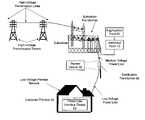
- FIG. 1is a diagram of an exemplary power distribution system with which the present invention may be employed
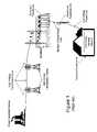
- FIG. 2is a diagram of the exemplary power distribution system of FIG. 1 modified to operate as a power line communication system, in accordance with an embodiment of the present invention
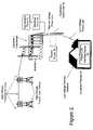
- FIG. 3is a schematic of a power line communication system in accordance with an embodiment of the present invention.
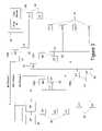
- FIG. 4is a block diagram of a bypass device, in accordance with an embodiment of the present invention.
- FIG. 5is a block diagram of a bypass device, in accordance with an embodiment of the present invention.
- FIGS. 6 a–cis a functional block diagram of a portion of a bypass device, in accordance with an embodiment of the present invention.
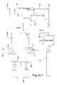
- FIG. 7is a schematic of a portion of a medium voltage interface for use in an embodiment of the present invention.
- FIG. 8is a schematic of a portion of an alternate medium voltage interface for use in an embodiment of the present invention.
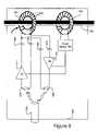
- FIG. 9is a functional block diagram illustrating of a portion of a bypass device, in accordance with an embodiment of the present invention.
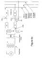
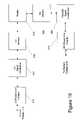
- FIG. 10is a functional block diagram of a bypass device, in accordance with another embodiment of the present invention.
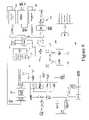
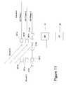
- FIG. 11is a schematic of backhaul point in a power line communication system, in accordance with an embodiment of the present invention.
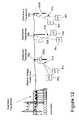
- FIG. 12is a diagram of a power distribution system modified to operate as a power line communication system, in accordance with another embodiment of the present invention.
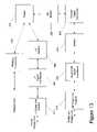
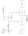
- FIG. 13is a functional block diagram of a bypass device, in accordance with another embodiment of the present invention.
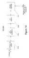
- FIG. 14is a functional block diagram of a communication device, in accordance with another embodiment of the present invention.
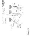
- FIG. 15is a schematic of a portion of a power line communication system in accordance with an embodiment of the present invention.
- FIG. 16is a schematic of a portion of a power line communication system in accordance with another embodiment of the present invention.
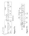
- FIGS. 17 a–bare schematics of a portion of a power line communication system in accordance an embodiment of the present invention.
- power distribution systemstypically include components for power generation, power transmission, and power delivery.
- a transmission substationtypically is used to increase the voltage from the power generation source to high voltage (HV) levels for long distance transmission on HV transmission lines to a substation.
- HVhigh voltage
- Typical voltages found on HV transmission linesrange from 69 kilovolts (kV) to in excess of 800 kV.
- power distribution systemsinclude MV power lines and LV power lines.
- MVtypically ranges from about 1000 V to about 100 kV and LV typically ranges from about 100 V to about 240 V.
- Transformersare used to convert between the respective voltage portions, e.g., between the HV section and the MV section and between the MV section and the LV section. Transformers have a primary side for connection to a first voltage (e.g., the MV section) and a secondary side for outputting another (usually lower) voltage (e.g., the LV section).
- Such transformersare often referred to as distribution transformers or a step down transformers, because they “step down” the voltage to some lower voltage. Transformers, therefore, provide voltage conversion for the power distribution system.
- poweris carried from substation transformer to a distribution transformer over one or more MV power lines. Power is carried from the distribution transformer to the customer premises via one or more LV power lines.
- a distribution transformermay function to distribute one, two, three, or more phase currents to the customer premises, depending upon the demands of the user. In the United States, for example, these local distribution transformers typically feed anywhere from one to ten homes, depending upon the concentration of the customer premises in a particular area. Distribution transformers may be pole-top transformers located on a utility pole, pad-mounted transformers located on the ground, or transformers located under ground level.
- the communication device of the present inventionmay form part of a PLCS to communicate signals to and from communication devices at the customer premises through the LV power line.
- the communication device of the present inventionmay facilitate the communication of data signals along the MV power line with 1) other power line communication devices; 2) one or more backhaul points; 3) one or more power line servers; and/or 4) devices on a network such as the Internet.
- FIG. 2One example of such a PLCS is shown in FIG. 2 and includes one or more bypass devices 100 , which may be formed by an embodiment of the present invention.
- the present inventionis embodied as a bypass device 100 to communicate data signals around the distribution transformer that would otherwise filter such data signals, preventing them from passing through the transformer.
- the communication device in this embodimentis a BD 100 that is the gateway between the LV power line subnet (i.e., the devices that are communicatively coupled to the LV power lines) and the MV power line.
- the BDprovides communication services for the user, which may include security management, routing of Internet protocol (IP) packets, filtering data, access control, service level monitoring, signal processing and modulation/demodulation of signals transmitted over the power lines.
- IPInternet protocol
- This example PLCSalso includes a backhaul point 10 , which may also be an alternate embodiment of the present invention.
- the backhaul point 10is an interface and gateway between a PLCS and a traditional non-power line telecommunication network.
- One or more backhaul points 10are communicatively coupled to an aggregation point (AP) 20 that in many embodiments may be the point of presence to the Internet.
- the backhaul point 10may be connected to the AP 20 using any available mechanism, including fiber optic conductors, T-carrier, Synchronous Optical Network (SONET), or wireless techniques well known to those skilled in the art.
- SONETSynchronous Optical Network
- the backhaul point 10may include a transceiver suited for communicating through the communication medium.
- the AP 20may include a conventional Internet Protocol (IP) data packet router and may be directly connected to an Internet backbone thereby providing access to the Internet.
- IPInternet Protocol
- the AP 20may be connected to a core router (not shown), which provides access to the Internet, or other communication network.
- a plurality of APs 20may be connected to a single core router which provides Internet access.
- the core router(or AP 20 as the case may be) may route voice traffic to and from a voice service provider and route Internet traffic to and from an Internet service provider.
- the routing of packets to the appropriate providermay be determined by any suitable means such as by including information in the data packets to determine whether a packet is voice.
- the packetmay be routed to the voice service provider and, if not, the packet may be routed to the Internet service provider.
- the packetmay include information (which may be a portion of the address) to determine whether a packet is Internet data. If the packet is Internet data, the packet may be routed to the Internet service provider and, if not, the packet may be routed to the voice service provider.
- the distribution pointmay be a router, may be coupled to a plurality of backhaul points 10 and provides routing functions between its backhaul points 10 and its AP 20 .
- a plurality of backhaul points 10are connected to each distribution point and each distribution point (of which there is a plurality) is coupled to the AP 20 , which provides access to the Internet.
- the PLCSalso may include a power line server (PLS) that is a computer system with memory for storing a database of information about the PLCS and includes a network element manager (NEM) that monitors and controls the PLCS.
- PLSpower line server
- NEMnetwork element manager
- the PLSallows network operations personnel to provision users and network equipment, manage customer data, and monitor system status, performance and usage.
- the PLSmay reside at a remote operations center to oversee a group of communication devices via the Internet.
- the PLSmay provide an Internet identity to the network devices by assigning the devices (e.g., user devices, BDs 100 , (e.g., the LV modems and MV modems of BDs), repeaters 70 , backhaul points 10 , and AP 20 ) an IP address and storing the IP address and other device identifying information (e.g., the device's location, address, serial number, etc.) in its memory.
- the PLSmay approve or deny user devices authorization requests, command status reports and measurements from the BDs, repeaters, and backhaul points, and provide application software upgrades to the communication devices (e.g., BDs, backhaul points, repeaters, and other devices).
- the PLSby collecting electric power distribution information and interfacing with utilities' back-end computer systems may provide enhanced distribution services such as automated meter reading, outage detection, load balancing, distribution automation, Volt/Volt-Amp Reactance (Volt/VAr) management, and other similar functions.
- the PLSalso may be connected to one or more APs and/or core routers directly or through the Internet and therefore can communicate with any of the BDs, repeaters, user devices, and backhaul points through the respective AP and/or core router.
- PLIDpower line interface device
- Various electrical circuits within the customer's premisesdistribute power and data signals within the customer premises.
- the customerdraws power on demand by plugging a device into a power outlet.
- the customermay plug the PLID 50 into a power outlet to digitally connect user devices to communicate data signals carried by the power wiring.
- the PLID 50thus serves as an interface for user devices to access the PLCS.
- the PLID 50can have a variety of interfaces for customer data appliances.
- a PLID 50can include a RJ-11 Plain Old Telephone Service (POTS) connector, an RS-232 connector, a USB connector, a 10 Base-T connector, RJ-45 connector, and the like.
- POTSPlain Old Telephone Service
- RS-232 connectorRS-232 connector
- USB connectorRS-232 connector
- 10 Base-T connector10 Base-T connector
- RJ-45 connector10 Base-T connector
- the user device connected to the PLID 50may be any device cable of supplying data for transmission (or for receiving such data) including, but not limited to a computer, a telephone, a telephone answering machine, a fax, a digital cable box (e.g., for processing digital audio and video, which may then be supplied to a conventional television and for transmitting requests for video programming), a video game, a stereo, a videophone, a television (which may be a digital television), a video recording device, a home network device, a utility meter, or other device.
- the PLID 50transmits the data received form the user device through the customer LV power line to a BD 100 and provides data received from the LV power line to the user device.
- the PLID 50may also be integrated with the user device, which may be a computer.
- the functions of the PLIDmay be integrated into a smart utility meter such as a gas meter, electric meter, water meter, or other utility meter to thereby provide automated meter reading (AMR).
- AMRautomated meter reading
- the BD 100typically transmits the data to the backhaul point 10 , which, in turn, transmits the data to the AP 20 .
- the AP 20then transmits the data to the appropriate destination (perhaps via a core router), which may be a network destination (such as an Internet address) in which case the packets are transmitted to, and pass through, numerous routers (herein routers are mean to include both network routers and switches) in order to arrive at the desired destination.
- a core routermay be a network destination (such as an Internet address) in which case the packets are transmitted to, and pass through, numerous routers (herein routers are mean to include both network routers and switches) in order to arrive at the desired destination.
- FIG. 3illustrates a power distribution network topology providing one example of a portion of a PLCS employing the present invention.
- the power distribution network shown in FIG. 3includes three MV phase conductors. Each of the three MV phase conductors is connected to one or more distribution transformers 60 .
- Each distribution transformer 60may include an associated BD 100 , although if no users receiving power from the distribution transformer subscribe to the PLCS service, the distribution transformer may not have an associated BD.
- Each BD 100is coupled to the MV power line and the LV power line connected to the transformer 60 , thereby providing a path for data around the transformer 60 .
- Each customer premises 40may include one or more PLIDs 50 and one or more user devices 80 . Those users who are not subscribers to the communication service may not have a PLID 50 or user device 80 connected to the PLCS.
- the PLCSmay have a maximum communication distance (MCD) (along the MV line) over which the backhaul point 10 and BD 100 may communicate reliably.
- MCDmaximum communication distance
- a distribution transformer 60 and its BD 100may be located more than the MCD away from the backhaul point 10 .
- the PLCSmay use BDs 100 located along the MV line as a repeater to repeat and/or amplify data. For example, if BD 100 c is more than the MCD from the backhaul point 10 , BD 100 b may repeat (i.e., receive and transmit on the MV line) data received from the backhaul point 10 that is intended for BD 100 c (or alternately repeat all data received on the MV line that is not intended for BD 100 b or its subnet).
- BD 100 bmay repeat data received from BD 100 c that is intended for backhaul point 10 or alternately repeat all data received on the MV line that is not received from the backhaul point 10 or that is not intended for BD 100 b or its LV subnet.
- a repeater 70is disposed between the backhaul point 10 and BD 100 a . While the repeater does not necessarily need not be near a distribution transformer, it may be more practical to install it near a distribution transformer (e.g., attached to the same pole) to allow the repeater to draw power from the LV power line extending from the transformer.
- the repeaterbecause it does not need to couple data to the LV power line—may be a self-contained device that couples to the MV line to draw power therefrom and communicate data therewith, thereby alleviating the need to provide electrical isolation from the LV power line.
- the repeater 70may function to repeat data in a manner similar to that described above with respect to the BD 100 b or may repeat all data received.
- the backhaul point 10 of FIG. 3is shown coupled to each phase of the MV power line. In practice, however, this may not be necessary. In some embodiments, such as those communicating through overhead MV conductors, data signals may couple across the MV conductors. In other words, data signals transmitted on one MV phase conductor may be present on all of the MV phase conductors due to the data coupling between the conductors. As a result, the backhaul point 10 may not need to be physically connected to all three phase conductors of the MV cable and transmission from the backhaul point 10 when coupled to one MV phase conductor will be received by the BDs 100 connected to the other MV phase conductors and vice versa. In some embodiments, however, which may include underground MV cables, it may be desirable to couple the backhaul point 10 to all of the available phase conductors.
- the following descriptionis for a communication device of the present invention that is embodied as a BD.
- the embodiment described immediately belowis a BD for bypassing a pole-mounted transformer.
- the present inventionis equally applicable for use in bypassing other types of transformers (such as pad mount and underground) and in other applications (such as repeaters and backhaul points) with minor modifications that will be evident to those skilled the art.
- the BDmay provide a path for data to bypass the transformer by being coupled to the same MV power line conductor that the transformer is coupled or to a different MV power line conductor and, in either instance, may be coupled to the same LV power lines to which the transformer is coupled.
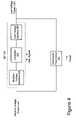
- the BD described hereinwhich is an example embodiment of the present invention, provides bi-directional communications and includes the functional block diagrams shown in FIG. 4 .
- the BD 100includes a MV power line interface (MVI) 200 , a controller 300 , and a LV power line interface (LVI) 400 .
- the BD 100is controlled by a programmable processor and associated peripheral circuitry, which form part of the controller 300 .
- the controller 300includes memory that stores, among other things, program code, which controls the operation of the processor.
- the LVI 400may include a LV power line coupler 410 , a LV signal conditioner 420 , and a LV modem 450 .
- the router 310forms part of the controller 300 and performs routing functions. Router 310 may perform routing functions using layer 3 data (e.g., IP addresses), layer 2 data (e.g., MAC addresses), or a combination of layer 2 and layer 3 data (e.g., a combination of MAC and IP addresses).
- the MVI 200may include a MV modem 280 , a first MV signal conditioner 260 , an isolator 240 , a second MV signal conditioner 220 , and a power line coupler 210 .
- the controller 300may perform other functions including controlling the operation of the LVI 400 and MVI 200 functional components. A more complete description of the controller 300 and its functionality is described below.
- this embodiment of the present inventionprovides bi-directional communications around the distribution transformer 60 to thereby provide a first communications path from the LV power line to the MV power line and a second path from the MV power line to the LV power line.
- the processing, and functional components of a communication path from the LV power line to the MV power line(the LV to MV path) will be described first. Subsequently, the processing and functional components of the communication path from the MV power line to the LV power line (the MV to LV path) will be described.
- the two pathsare logical paths.
- the LV to MV path and the MV to LV pathmay be separate physical electrical paths at certain functional blocks and may be the same physical path in other functional blocks.
- other embodiments of the present inventionmay provide for a completely, or substantially complete, separate physical path for the LV to MV and the MV to LV paths.
- the LV power linetypically includes a neutral conductor and two conductors carrying current (“energized”) conductors.
- the two energized conductorstypically carry about 120V alternating current (AC) at a frequency of 60 Hz and are 180 degrees out of phase with each other.
- the present inventionis suitable for LV power line cables having conductors that are spaced apart or that are coupled together (e.g., in a twisted pair or via the conductor insulation).
- the LVI 400includes a LV power line coupler 410 that couples data to and from the LV power line and may include a transducer.
- the coupler 410also may couple power from the LV power line, which is used to power at least a portion of the BD 100 .
- the electronics of much of the BD 100is housed in an enclosure with first and second BD cables extending from the enclosure.
- the first BD cableincludes a twisted pair of conductors including a signal conductor and neutral conductor.
- the first conductor of the first BD cableis connected to one of the energized LV conductors extending from the transformer and the second conductor of the first BD cable is connected to the neutral conductor extending from the transformer.
- clamping the BD conductors to the LV power line conductorsmakes the connection.
- the second BD cable extending from the enclosureis also a twisted pair comprised of a first and second conductor.
- the first conductor of the second BD cableis connected to the neutral conductor extending from the transformer and the second conductor of the second BD cable is connected to the second (other) energized LV conductor extending from the transformer.
- the third BD cableis a ground conductor that may be connected to an earth ground, which typically is an earth ground conductor that connects the transformer housing to a ground rod.
- the neutral conductor of the LV power linemay also be connected to the earth ground of the power line system (by the electric power company). However, their may be an intrinsic RF impedance between the BD ground conductor connection and the LV neutral conductor connections of the BD (i.e., the second conductor of the first BD cable and the first conductor of the second BD cable). Additionally, it may be desirable to add an RF impedance (e.g., an RF choke) between the connections.
- an RF impedancee.g., an RF choke
- the LV coupler 410may include a transducer and may be an inductive coupler such as toroid coupling transformer or a capacitive coupler, for coupling data to and/or from the LV power line and/or for coupling power from the LV power line.
- an inductive couplersuch as toroid coupling transformer or a capacitive coupler
- the signals entering the BD 100 via the first and second BD cablesare processed with conventional transient protection circuitry, which is well-known to those skilled in the art.
- the first signal and second signalare processed with voltage translation circuitry.
- the data signals in this embodimentwhich are in the 4.5 to 21 MHz band, “ride on” (i.e., are additive of) the low frequency power signal (the 120V 60 Hz voltage signal). Consequently, in this embodiment, it is desirable to remove the low frequency power signal, but to keep the data signals for processing, which is accomplished by the voltage translation circuitry.
- the voltage translation circuitrymay include a high pass filter to remove the low frequency power signal and may also (or instead) include other conventional voltage translation circuitry.
- the first and second signalsmay be processed with impedance translation circuitry, which is well-known in the art.
- impedance translation circuitrywhich is well-known in the art.
- One method of matching the impedance of the LV power lineis to separately terminate the BD LV conductors of the first and second BD cables through a termination resistor to ground.
- the value of the termination resistormay be selected to match the characteristic impedance of the LV power line.
- the electronics of the BD 100 that are on the LV side of the isolator 240may be powered by power received from the LV power line.
- this embodiment of the BD 100includes a power supply for powering much of the BD 100 electronics.
- the power supplymay include its own transient protection circuitry, which may be in addition to, or instead of, the transient protection circuitry that processes the data signals described above.
- the power supplymay receive power from the BD LV conductor of the first (or second) BD cable after the power signal passes through the transient protection circuitry.
- the BD 100may include a battery backup for operating the BD 100 during power outages.
- a backup power system(which may include a battery) may allow the device to detect a power outage and communicate information relating to the outage to the utility company and/or PLS. In practice, information of the outage may be transmitted to the PLS, which communicates the location, time, and/or other information of the outage to the power utility (e.g., the utility's computer system).
- the backup power systemalso may allow the BD 100 to communicate certain data packets during a power outage. For example, during an outage, the BD 100 may be programmed to communicate all voice data or only emergency voice transmissions (e.g., phone calls dialed to 911).
- the PLSmay also determine the location and/or area of a power outage. Periodically, the PLS may ping each (or some subset of) network element. The determination of a power outage may be made by a failure of a network element to respond to the periodic ping (or other command or request) transmitted by the PLS. If the network element has an alternate power source such as a batter backup, the network element may transmit a notification of the power outage (e.g., based on a low voltage measurement by the network element).
- the PLScan retrieve the network element's physical location (such as its pole number, which may be mapped to a longitude and latitude and/or street address) from memory to determine the location of the power outage.
- the PLSmay map an area without power.
- Information of the power outage, such as the location(s) time, etc.,may then be transmitted to the utility company.
- the BD 100may either transmit data to, or receive data from, the LV power line at any one instant. From the user's perspective, however, the communications may seem simultaneous because the change in direction of data flow (from transmit to receive and vice versa) is very fast and transmission and reception is contemporaneous over very short periods of time.
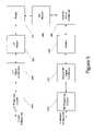
- FIG. 6is a block diagram of a portion of a bypass device.
- the processor of the controller 300controls a set of switches 426 (e.g., Field-effect Transistor (FET) switches), which when in a first configuration permit reception and when in a second configuration permit transmission thereby providing a fast LV transmit/receive switch 426 for communicating through the LV power lines.
- switches 426e.g., Field-effect Transistor (FET) switches
- the LV data signalsare in the frequency band of approximately 4.5 to 21 MHz and, as discussed, the data signals “ride on” the low frequency power signal.
- the two energized LV conductorstypically are kept separate electrically, there is significant coupling of data signals between the energized LV conductors at these frequencies. Consequently, a signal sent on one energized LV conductor from the customer premises typically will be present on both energized LV conductors at the BD 100 .
- the LV power lineoften does not, however, have a flat frequency response over the frequency band of the data signals, which is especially true for underground power distribution system cables. More specifically, LV power lines sometimes have a greater loss at higher frequencies than at lower frequencies. To compensate for the nonlinearity of the LV power line communication channel, this embodiment of the present invention provides separate, and potentially different, signal processing for the higher frequencies.
- the first signal(comprising data signals from the BD LV conductor of the first cable) is supplied to a first filter 421 a that has a pass band of approximately 4.0 to 10 MHz.
- the second signal(comprising data signals from the BD LV conductor of the second BD cable) is supplied to a second filter 421 b that has a pass band of approximately 10–21 MHz.
- Each of these filters 421provides pass band filtering and may also provide anti-aliasing filtering for their respective frequency bands, and noise filtering.
- the outputs of the first and second filters 421 a–bare supplied to a first amplifier 422 a and second amplifier 422 b , respectively.
- the outputs of the first and second amplifiers 422 a–bare coupled to a first feedback device 423 a and a second feedback device 423 b , respectively.
- Each feedback device 423measures the power over time and supplies the power measurement to the controller 300 . Based on the power measurement, the controller 300 increases, decreases, or leaves the gain of the associated amplifiers the same to provide automatic gain control (AGC).
- AGCautomatic gain control
- the outputs of the first and second amplifiers 422are also supplied to a summation device 424 that sums the two pass band, amplified signals to provide a single data signal.
- the gain of the second amplifier 422 bwhich receives signals in the 10–21 MHz band, may be greater (or may be dynamically made greater) than the gain of the first amplifier 422 a , which receives signals in the 4.5 to 10 MHz band.
- the higher gain of the second amplifier filter 422 bcan thus compensate for the greater loss of the transmission channel at the higher frequencies.
- the amplification by the amplifiers 422is accomplished by amplifying the signal a first predetermined amount, which may be the same or different (e.g., such as proportional to the anticipated loss of the channel) for each amplifier.
- the amplified signalis then attenuated so that the resultant amplified and subsequently attenuated signal is at the appropriate amplification with respect to the original signal, which may be determined by controller 300 from information received by the feedback devices 423 .
- the feedback device 423may be implemented with suitable feedback architecture, well-known to those skilled in the art.
- the feedback devices 423may use both hardware (such as feedback that may be provided by an analog to digital converter) and software (such as in modifying the reference voltage supplied to an operational amplifier that is implementing amplifier 422 ).
- Other embodimentsmay not include filtering the inputs of the two BD LV conductors at separate pass bands and separately amplifying the filtered signals. Instead, the signal may be filtered and amplified across the entire LV power line communication pass band (e.g., from 4.5 to 21 MHz). Similarly, while this embodiment divides the LV power line communication channel into two bands (for filtering, amplifying and summing), other embodiments may similarly divide the LV power line communication channel into three, four, five or more bands (for filtering, amplifying and summing).
- the output of the summing device of the LV signal conditioner 420is supplied to the LV modem 450 , which includes a modulator and demodulator.
- the LV modem 450also may include one or more additional functional submodules such as an Analog-to-Digital Converter (ADC), Digital-to-Analog Converter (DAC), a memory, source encoder/decoder, error encoder/decoder, channel encoder/decoder, MAC (Media Access Control) controller, encryption module, and decryption module.
- ADCAnalog-to-Digital Converter
- DACDigital-to-Analog Converter
- memorysource encoder/decoder
- error encoder/decodererror encoder/decoder
- channel encoder/decoderchannel encoder/decoder
- MACMedia Access Control
- encryption moduleand decryption module.
- the LV modem 450is formed, at least in part, by part number INT5130, which is an integrated power line transceiver circuit incorporating most of the above-identified submodules, and which is manufactured by Intellon, Inc. of Ocala, Fla.
- the incoming signal from the summation device 424is supplied to the ADC to convert the incoming analog signal to a digital signal.
- the digital signalis then demodulated.
- the LV modem 450then provides decryption, source decoding, error decoding, channel decoding, and media access control (MAC) all of which are known in the art and, therefore, not explained in detail here.
- the LV modem 450may examine information in the packet to determine whether the packet should be ignored or passed to the router 310 . For example, the modem 450 may compare the destination MAC address of the packet with the MAC address of the LV modem 450 (which is stored in the memory of the LV modem 450 ). If there is a match, the LV modem 450 removes the MAC header of the packet and passes the packet to the router 310 . If there is not a match, the packet may be ignored.
- the data packet from the LV modem 450may be supplied to the router 310 , which forms part of the controller 300 .
- the router 310performs prioritization, filtering, packet routing, access control, and encryption.
- the router 310 of this example embodiment of the present inventionuses a table (e.g., a routing table) and programmed routing rules stored in memory to determine the next destination of a data packet.
- the tableis a collection of information and may include information relating to which interface (e.g., LVI 400 or MVI 200 ) leads to particular groups of addresses (such as the addresses of the user devices connected to the customer LV power lines), priorities for connections to be used, and rules for handling both routine and special cases of traffic (such as voice packets and/or control packets).
- the router 310will detect routing information, such as the destination address (e.g., the destination IP address) and/or other packet information (such as information identifying the packet as voice data), and match that routing information with rules (e.g., address rules) in the table.
- the rulesmay indicate that packets in a particular group of addresses should be transmitted in a specific direction such as through the LV power line (e.g., if the packet was received from the MV power line and the destination IP address corresponds to a user device connected to the LV power line), repeated on the MV line (e.g., if the BD 100 is acting as a repeater), or be ignored (e.g., if the address does not correspond to a user device connected to the LV power line or to the BD 100 itself.
- the tablemay include information such as the IP addresses (and potentially the MAC addresses) of the user devices on the BD's LV subnet, the MAC addresses of the PLIDs 50 on the BD's LV subnet, the MV subnet mask (which may include the MAC address and/or IP address of the BD's backhaul point 10 ), and the IP address of the LV modem 450 and MV modem 280 .
- the routermay pass the packet to the MV modem 280 for transmission on the MV power line.
- the BD 100may process the packet as a request for data.
- the routermay prevent packets from being transmitted to any destination other than a DNS server or registration server.
- the router 310may replace any request for a web page received from that user device with a request for a web page on the registration server (the address of which is stored in the memory of the router).
- the router 310may also prioritize transmission of packets. For example, data packets determined to be voice packets may be given higher priority for transmission through the BD than data packets so as to reduce delays and improve the voice connection experienced by the user. Routing and/or prioritization may be based on IP addresses, MAC addresses, subscription level, or a combination thereof (e.g., the MAC address of the PLID or IP address of the user device).
- the MV modem 280receives data from the router 310 and includes a modulator and demodulator.
- the MV modem 280also may include one or more additional functional submodules such as an ADC, DAC, memory, source encoder/decoder, error encoder/decoder, channel encoder/decoder, MAC controller, encryption module, and decryption module.
- additional functional submodulessuch as an ADC, DAC, memory, source encoder/decoder, error encoder/decoder, channel encoder/decoder, MAC controller, encryption module, and decryption module.
- These functional submodulesmay be omitted in some embodiments, may be integrated into a modem integrated circuit (chip or chip set), or may be peripheral to a modem chip.
- the MV modem 280is formed, at least in part, by part number INT5130, which is an integrated power line transceiver circuit incorporating most of the identified submodules and which is manufactured by Intellon, Inc. of Ocala, Fla.
- the incoming signal from the router 310is supplied to the MV modem 280 , which provides MAC processing, for example, by adding a MAC header that includes the MAC address of the MV modem 280 as the source address and the MAC address of the backhaul point 10 (and in particular, the MAC address of the MV modem of the backhaul point) as the destination MAC address.
- the MV modem 280also provides channel encoding, source encoding, error encoding, and encryption. The data is then modulated and provided to the DAC to convert the digital data to an analog signal.
- the modulated analog signal from MV modem 280is provided to the first MV signal conditioner 260 , which may provide filtering (anti-alias, noise, and/or band pass filtering) and amplification.
- the MV signal conditioner 260may provide frequency translation.
- the translationis from the 4–21 MHz band of the LV power line to the band of the MV power line, which in this embodiment is a higher frequency band.
- translation of the frequencyis accomplished through the use of a local oscillator and a conversion mixer. This method and other methods of frequency translation are well known in the art and, therefore, not described in detail.
- frequency translationmay result in a first and second image of the original frequency although in some instances, such as in the present embodiment, only one of the two images is desired.
- the frequency translation circuitrymay include an image rejection filter to filter out the undesired image leaving only the desired frequency bandwidth, which in this embodiment is the higher frequency band of the MV power line.
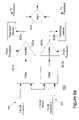
- the isolator 240 of the present embodimentprovides isolation for both the LV to MV path and the MV to LV path that is substantially the same.
- the isolator 240provides electrical isolation between the MV power line and the LV power line, thereby ensuring that the higher voltages of the MV power line do not reach the LV power line or the customer premises.
- the isolator 240 in this embodimentensures that the voltages of the MV power line do not reach the electronics on the LV side of the isolator 240 , which may be referenced to the neutral of the LV power line.
- the output of the MV first signal conditioner 260may be supplied to the isolator 240 , which may be a fiber optic isolator comprising a fiber optic transmitter (or transceiver) on the LV side of the isolator 240 and a fiber optic receiver (or transceiver) on the MV side of the isolator 240 .
- a fiber optic transmitter (or receiver)shall include a transmitter (or receiver) that forms part of a fiber optic transceiver.
- the fiber optic transmitter and fiber optic receiver (or transceivers)are communicatively coupled through a fiber optic conductor(s) or light pipe(s).
- an inductive isolatorsuch as in a transformer
- a capacitive isolatorsuch as in a capacitive isolator
- a wireless isolator pathsuch as a Bluetooth® wireless path, an 802.11 wireless path, or an ultrawideband wireless path
- the isolator 240also may include isolation signal conditioning circuitry that filters (e.g., band pass, anti-aliasing, noise), amplifies, and/or performs other processing or conditioning of the signal, which may be necessary for interfacing the isolator with the surrounding components of the device.
- the isolation signal conditioning circuitrymay be on the LV side of the isolator and/or on the MV side of the isolator 240 . While the isolator in this embodiment forms part of the MVI 200 , the isolator may instead form part of the LVI 400 .
- the isolator 240supplies the signals to the second MV signal conditioner 220 on the MV side of the isolator 240 .
- the second MV signal conditioner 220may condition the signal by filtering and/or amplifying the signal.
- the signalmay buffer the signal and provide load balancing.
- the output of these conditioning elementsmay be supplied to a MV transmit/receive switch (not shown), which controls whether the BD 100 is transmitting or receiving on the MV power line.
- the MV transmit/receive switchmay default to receive mode so that data received from the MV line will pass through the switch to the receive circuitry.
- the MV transmit/receive switchalso may be coupled to a transmission detection circuit, which detects when data is being provided for transmission on the MV line from the router 310 (for example, which may have originated from a user device). When the transmission detect circuitry detects transmission data, the circuitry transitions the switch to transmit mode so that the data to be transmitted may pass through the MV transmit/receive switch to the MV power line.
- Data passing through the MV transmit/receive switch for transmission on the MV power lineis supplied to the MV power line coupler 210 , which may include impedance translation circuitry, transient suppression circuitry, and a coupling device.
- the coupling devicecouples the data onto the MV power line as a transmission.
- the coupling devicemay be inductive, capacitive, conductive, a combination thereof, or any suitable device for communicating data signals to and/or from the MV power line.
- a coupleris described in U.S. application. Ser. No. 10/176,500, entitled “Power Line Coupling Device and Method of Using the Same,” which is hereby incorporated by reference.
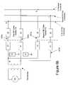
- the coupling deviceincludes a data filter which may be radio frequency (RF) filter or RF choke 705 communicatively coupled to the MV power line between the connection nodes as shown in FIG. 7 .
- the RF choke 705provides the impedance with inductors (e.g., ferrite toroids) disposed in the inductor chambers of a housing. Inductances may range from about 0.1 microHenries to 5.0 microHenries.
- the RF choke 705operates as a low pass filter.
- low frequency signalse.g., having a frequency of 50 or 60 Hz
- High frequency signalse.g., a data signal
- the RF choke 705can be modeled as a high impedance circuit to high frequency signals.
- the voltage across the RF choke 705includes data signals but substantially no power signals.
- This voltage(i.e., the voltage across the RF choke 705 ) is applied to transformer 720 via capacitors 710 to receive data signals from MV power line.
- a data signalis applied to transformer 720 , which in turn communicates the data signal to MV power line through capacitors 710 .
- Capacitors 710provide some electrical isolation between MV power line and transformer 720 . Capacitors 710 further provide filtering of stray power signals. That is, the data signal passes across capacitors 710 while any lower frequency power signals are substantially prevented from passing across capacitors 710 .
- Transformer 720may operate as a differential transceiver. That is, transformer 720 may operate to repeat data signals received from the MV power line to receive circuitry 612 and to repeat data signals received from transmit circuitry 610 to the MV power line. Transformer 720 also provides some electrical isolation between MV power line and LV power line. Transformer 720 also permits RF signals, such as data signals, to pass through and travel on down the power line.
- this coupling deviceis coupled to an isolator 240 comprised of a fiber optic transceiver.
- Capacitors 606are electrically connected between transmit circuitry 610 and receive circuitry 612 and transformer 720 .
- Transmit circuitry 610 and receive circuitry 612are electrically connected to transmit optoelectronic device 620 and receive optoelectronic device 622 , respectively.
- Transmit optoelectronic device 620e.g., a photo diode
- receive optoelectronic device 622e.g., a photo detector
- the communication medium 630 of the isolatoris a fiber optic cable that provides electrical power isolation between MV power line and LV power line.
- powermay be supplied to the MV side of the isolator 240 via a power supply that includes a transducer (e.g., a photo cell array) that converts non-electrical energy (e.g., light) into electrical energy.
- the non-electrical energy in this exampleis light that is supplied to the power supply via a light pipe or fiber optic cable 631 and has an energy source that is a light source powered from power supplied from the LV power line.
- a power supplyis disclosed in U.S. application. Ser. No. 10/292,745, Attorney Docket No. CRNT-0079, entitled “A Floating Power Supply and Method of Using the Same” filed Nov. 12, 2002, which is hereby incorporated by reference.
- the couplerincludes an inductive coupling device having a toroid 602 with windings 604 that form part of a coupling transformer.
- the couplerincludes a power coupling device 680 (e.g., a toroid transformer) that supplies electrical energy to a power supply 682 to power the electronics on the MV side of the isolator 240
- the first MV signal conditioner 220also may be omitted or combined with the second MV signal conditioner 260 when using such a coupler.
- a combined signal conditionermay include a MV transmit/receive switch, a filter (e.g., include one or more of band pass, noise, or anti-alias filter) an amplifier, and a frequency translator.
- a BD 100 employing this couplermay include the functional components shown in FIG. 10 .
- the MV power line coupler 210also receives data signals from the MV power line via a coupling device, which may take the form of any of those coupling devices described above.
- the data signals from the MV couplerpass through the transient suppression circuitry and impedance translation circuitry to the MV transmit/receive switch.
- the switchwhen in receive mode, passes the incoming data signal to the second MV signal conditioner 220 , which may provide band pass filtering of the signal (e.g., filtering out signals outside the frequency band of interest), amplification of the signal, and additional filtering (e.g., image rejection filtering, anti-aliasing, noise).
- the signalis then supplied to the isolator 240 , which in this one embodiment is a fiber optic cable and transceivers.
- the isolator 240 of the present embodimentprovides isolation for both the LV to MV path and the MV to LV path.
- the input to the isolator 240may be conditioned with signal conditioning circuitry associated with the isolator.
- signal conditioning circuitrymay include circuitry that filters (e.g., band pass, anti-aliasing, noise), amplifies, and/or performs other processing or conditioning of the signal.
- the isolator 240is comprised of a fiber optic isolator including a fiber optic transceiver on the LV side of the isolator and a fiber optic transceiver on the MV side of the isolator. As discussed, the fiber optic transceivers are communicatively coupled through a fiber optic conductor(s) or light pipe(s).
- the isolator 240provides electrical power isolation between the MV power line and the LV power line, thereby ensuring that the higher voltages of the MV power line to not reach the LV power line or the customer premises.
- the isolator 240ensures that the voltages of the MV power line do not reach the electronics on the LV side of the isolator, which are referenced to the neutral of the LV power line. While this embodiment employs a fiber optic based isolator, other embodiments may use an inductive isolator (such as in a transformer), a capacitive isolator, a wireless path (such as a Bluetooth® wireless path, an 802.11 wireless path, an ultrawideband (need more info) wireless path), or some combination thereof.
- the isolator 240may include isolation signal conditioning circuitry that filters (e.g., band pass, anti-aliasing, noise, etc.), amplifies, and/or performs other processing or conditioning of the signal.
- the isolation signal conditioning circuitrymay be on the input or output of the isolator 240 and form part of either communication path as is necessary.
- the output of the isolator 240is provided to the first MV signal conditioner 260 , which may include a low pass filter for filtering out signals above the uppermost frequency of interest or a band pass filter for filtering out signals outside the MV communication channel band.
- the conditioner 260 of this example embodimentincludes a frequency translator circuit to shift the frequency of the signal from the frequencies of the MV communication channel to those of the LV communication channel (e.g., 4.5–21 MHz).
- the second MV signal conditioner 260may also include an additional filter after the frequency translation, which may include anti-alias filtering, and/or band pass filtering.
- the signal conditioner 260may include an amplifier for amplifying the signal.
- the MV modem 280receives the output of the first MV signal conditioner 260 .
- the MV modem 280 and LV modem 450provide a bidirectional path and form part of the MV to LV path and the LV to MV path.
- the components of the MV modem 280have been described above in the context of the LV to MV path and are therefore not repeated here.
- the incoming signalis supplied to the ADC to convert the incoming analog signal to a digital signal.
- the digital signalis then demodulated.
- the modemthen provides decryption, source decoding, error decoding, and channel decoding all of which are known in the art and, therefore, not explained in detail here.
- the MV modem 280also provides MAC processing through the use of MAC addresses.
- the MAC addressis used to direct data packets to the appropriate device.
- the MAC addressesprovide a unique identifier for each device on the PLC network including, for example, user devices, BDs, PLIDs, repeaters and backhaul points (i.e., the LV modems and MV modems of the BDs, repeaters, and the backhaul points).
- the backhaul point 10will determine the MAC address of the MV modem 280 of the BD 100 servicing the user device. The information for making this determination is stored in a table in the memory of the backhaul point 10 . The backhaul point 10 will remove the MAC header of the packet and add a new header that includes the MAC address of the backhaul point 10 (as the source address) and the MAC address of the BD 100 (the destination address)—or more specifically, the MAC address of the MV modem 280 of the destination BD 100 .
- packets destined for a user device on a LV subnet of a BD 100are addressed to the MAC address of the MV modem 280 of the BD 100 and may include additional information (e.g., the destination IP address of the user device) for routing the packet to devices on the BD's LV subnet.
- additional informatione.g., the destination IP address of the user device
- the packetmay be discarded (ignored). If the destination MAC address of the received packet does match the MAC address of the MV modem 280 , the MAC header is removed from the packet and the packet is supplied to the router 310 for further processing.
- MAC sublayerfor each physical device type such as for user devices and PLCS network elements (which may include any subset of devices such as backhaul devices, BDs, repeaters, aggregation points, and core routers).
- the MV modem 280 of a BD 100upon reception of a data packet, the MV modem 280 of a BD 100 will determine if the destination MAC address of the packet matches the MAC address of the MV modem 280 and, if there is a match, the packet is passed to the router 310 . If there is no match, the packet is discarded.
- the router 310analyzes packets having a destination IP address to determine the destination of the packet which may be a user device or the BD 100 itself. This analysis includes comparing the information in the packet (e.g., a destination IP address) with information stored in memory, which may include the IP addresses of the user devices on the BD 100 LV subnet. If a match is found, the router 310 routes the packet through to the LV modem 450 for transmission on the LV power line. If the destination IP address matches the IP address of the BD 100 , the packet is processed as a command or data intended for the BD 100 (e.g., by the Command Processing software described below) and may not be passed to the LV modem 450 .
- a destination IP addresse.g., a destination IP address
- routeris sometimes used to refer to a device that routes data at the IP layer (e.g., using IP addresses).
- switchis sometimes used to refer to a device that routes at the MAC layer (e.g., using MAC addresses).
- routerrouting
- routing functionsrouting functions
- the terms “router”, “routing”, “routing functions” and the likeare meant to include both routing at the IP layer and MAC layer. Consequently, the router 310 of the present invention may use MAC addresses instead of, or in addition to, IP addresses to perform routing functions.
- Transmission Control Protocol (TCP)/IPincludes a facility referred to as the Address Resolution Protocol (ARP) that permits the creation of a table that maps IP addresses to MAC addresses.
- the tableis sometimes referred to as the ARP cache.
- the router 310may use the ARP cache or other information stored in memory to determine IP addresses based on MAC addresses (and/or vice versa).
- the ARP cache and/or other informationmay be used with information in the data packet (such as the destination IP address) to determine the routing of a packet (e.g., to determine the MAC address of the PLID communicating with the user device having the destination IP address).
- all packets received by the MV modem 280may be supplied to the router 310 .
- the router 310may determine whether the packet includes a destination IP address that corresponds to a device on the BD's LV subnet (e.g., an address corresponding to a user device address or the BD's address). Specifically, upon determining the destination IP address of an incoming packet, the router 310 may compare the identified destination address with the addresses of the devices on the subnet, which are stored in memory. If there is a match between the destination address and the IP address of a user device stored in memory, the data is routed to the LV power line for transmission to the user device. If there is a match between the destination address and the IP address of the BD 100 stored in memory, the data packet is processed as a command or information destined for the BD 100 .
- the router 310may also compare the destination address with the IP address of the backhaul point 10 , other BDs, or other repeaters (for example, if the BD is also acting as a repeater). If there is no match between the destination address and an IP address stored in memory, the packet is discarded (ignored).
- the routermay perform any or all of prioritization, packet routing, access control, filtering, and encryption.
- the router 310 of this example embodiment of the present inventionmay use a routing table to determine the destination of a data packet. Based on information in the routing table and possibly elsewhere in memory, the router 310 routes the packets. For example, voice packets may be given higher priority than data packets so as to reduce delays and improve the voice connection experienced by the user.
- the router 310supplies data packets intended for transmission along the LV power line to the LV modem 450 .
- the LV modem 450After receiving the data packet from the router 310 , the LV modem 450 provides MAC processing, which may comprise adding a MAC header that includes the source MAC address (which may be the MAC address of the LV modem 450 ) and the destination MAC address (which may be the MAC address of the PLID 50 corresponding to the user device identified by the destination IP address of the packet).
- MAC processingmay comprise adding a MAC header that includes the source MAC address (which may be the MAC address of the LV modem 450 ) and the destination MAC address (which may be the MAC address of the PLID 50 corresponding to the user device identified by the destination IP address of the packet).
- the LV modem 450To determine the MAC address of the PLID 50 that provides communications for the user device identified by the destination IP address of the packet, the LV modem 450 first determines if the destination IP address of the packet is an IP address stored in its memory (e.g., stored in its bridging table). If the IP address is stored in memory, the LV modem 450 retrieves the MAC address for communicating with the destination IP address (e.g., the MAC address of the PLID 50 ) from memory, which will also be stored therein. If the IP address is not stored in memory, the LV modem 450 transmits a request to all the devices to which it is coupled via the low voltage power line (e.g., all the PLIDs).
- the low voltage power linee.g., all the PLIDs
- the requestis a request for the MAC address for communicating with the destination IP address of the packet.
- the devicee.g., the PLID
- the LV modem 450stores the received MAC address and the IP address for which the MAC address provides communications in its memory (e.g., in its bridging table).
- the LV modem 450then adds the received MAC address as the destination MAC address for the packet.
- the packetis then channel encoded, source encoded, error encoded, and encrypted.
- the datais then modulated and provided to the DAC to convert the digital data to an analog signal.
- the output of the LV modem 450is provided to the LV signal conditioner 420 , which conditions the signal for transmission. Knowing (or determining) the frequency response (or loss) of the LV power line transmission channel allows the device to predistort signals prior to transmission to compensate for anticipated losses at certain frequencies or frequency ranges. During and/or prior to transmission, the amount of amplification necessary for particular frequency ranges may be periodically determined according to methods known in the art to provide dynamic predistortion (i.e., changing the amount of amplification of all or portions (e.g., frequencies or frequency ranges) of the signal over time) of the transmitted signal.
- the determination of the desired amount of amplificationmay, for example, be determined and/or relate to the amount of amplification performed by amplifiers 422 in the LV to MV path.
- the amplificationmay be characteristic for a particular type of channel (e.g., overhead or underground), or measured for a channel, and the predistortion thus may be fixed (preprogrammed and/or hardwired into the device).
- signals at higher frequenciesare amplified more than signals at lower frequencies to compensate for the anticipated greater loss at the higher frequencies.
- the signal to be transmittedis amplified with an amplifier that provides greater amplification at higher frequencies of the 4.5 to 21 MHz band.
- the amplifiermay have a transfer function substantially inverse to the frequency response of the LV transmission channel.
- the signalis conducted through switch 426 to the LV power line coupler 410 for transmission on the energized LV conductors of the LV power line.
- the transmissionmay not be predistorted and may be filtered and amplified substantially the same across the transmission channel.
- FIG. 6 billustrates the transmit circuit used to drive the data signal (indicated by Vs). Components to the left of the dashed line in FIG. 6 b may be inside the BD enclosure and those to the right may be outside the BD enclosure.
- the transmit circuit of this embodimentis comprised of a transformer that drives the two conductor pairs 436 and 437 . Each conductor pair 436 , 437 is coupled to ground by impedance Z 3 , which may be resistive.
- each conductor 436 a,b and 437 a,bincludes a series impedance Z 1 , which may be capacitive (e.g., providing a high pass filter) and/or resistive.
- the first and second BD cables 436 , 437are each comprised of a twisted pair of conductors 436 a,b and 437 a,b .
- each twisted pair cable 436 , 437will have an impedance (determined by the geometry of the cable) as represented by Z 2 in FIG. 6 b .
- This impedance Z 2may be modeled by a resistive component and an inductive component. The inductive component also may cause coupling between the two twisted conductors of each cable.
- the LV power line coupler 410may include the impedance matching circuitry and transient protection circuitry.
- the coupler 410couples the data signal onto the LV power line as described above for reception by a user device communicatively coupled to the LV power line via a PLID.
- the LV energized conductorsAfter the LV energized conductors enter the customer premises, typically only one LV energized conductor will be present at each wall socket where a PLID might be installed (e.g., plugged in). Given this fact regarding the internal customer premises wiring, there is no way to know to which LV energized conductor the PLID (and user device) will be connected. In addition, the subscriber may move the PLID and user device to another socket to access the PLCS and the new socket may be coupled to the second (different) LV energized conductor. Given these facts, the network designer must supply communications on both LV energized conductors and, therefore, would be motivated to simultaneously transmit the PLC RF data signal on each LV energized conductor referenced to the neutral conductor. However, in comparison to transmitting the RF data signals on both energized conductors referenced to the neutral, the following method of providing communications on the LV energized has been found to provide improved performance.
- the first BD cable 436is coupled to the LV power line so that the data signal is applied to the first LV energized conductor referenced to the LV neutral conductor.
- the second BD cable 437is coupled to the LV power line so that the data signal (Vs) is applied to the neutral conductor referenced to the second LV energized conductor.
- Vsdata signal
- the data signalis applied to the first and second LV energized conductors differentially.
- the voltage signal (representing the data) on the second LV energized conductoris equal in magnitude and opposite in polarity of the voltage on the first LV energized conductor.
- the current flow representing the data on the second LV energized conductorwill be the opposite of the current flow on the first LV energized conductor in magnitude and direction. It has been found that differentially driving the LV energized conductors as described provides significant performance improvements over methods, which may result from reduced reflections, improved signal propagation, and impedance matching among other things. It is worth noting the transmit circuit of this and the following embodiments may transmit data signals with multiple carriers (e.g., eighty or more) such as with using an Orthogonal Frequency Division Multiplex (OFDM) modulation scheme.
- OFDMOrthogonal Frequency Division Multiplex
- FIG. 6 cillustrates another embodiment of a transmit circuit for transmitting the data signal.
- Components to the left of the dashed line in FIG. 6 cmay be inside the BD enclosure and those to the right may be outside the BD enclosure.
- the transmit circuit of this embodimentis comprised of a transformer that drives one conductor pair 436 , which traverse through a common mode choke.
- the common mode chokeprovides a very low impedance to differential currents in the two conductors 436 a,b , but provides a significant or high impedance to common mode currents (i.e., currents traveling in the same direction such as in or out).
- the two conductors 436 a,bmay also be coupled to ground by an impedance Z 3 , which may be a resistive impedance.
- each conductor 436 a , bincludes a series impedance Z 1 , which may be a capacitive impedance, or other low pass filter component(s), for impeding the 60 Hz power signal and permitting the RF data signal to pass unimpeded.
- Such impedancesmay be on either side of the common mode choke, but are preferably on the LV power line side of the choke.
- each conductormay also include a surge protection circuit, which in FIG. 6 c are shown as S 1 and S 2 .
- the cable 436may be comprised of a twisted pair of conductors between the BD enclosure and LV power line.
- the twisted pair cable 436may have an impedance (determined by the geometry of the cable) as represented by Z 2 .
- This impedance Z 2may be modeled by a resistive component and an inductive component. The inductive component also may cause coupling between the two twisted wired conductors.
- the transmit circuit of either embodimentmay also include a fuse in series with each conductor and a voltage limiting device, such as a pair of oppositely disposed zener diodes, coupled between the pair of conductors and may be located between the common mode choke and the transformer.
- a voltage limiting devicesuch as a pair of oppositely disposed zener diodes
- one of the conductors of the BD cable(s) 436 or 437may used to supply power to the power supply of the BD 100 to power the BD 100 .
- these embodiments of the present inventiondrive the first and second LV energized conductors differentially to transmit the data signal (e.g., using OFDM).
- the PLIDtransmits data signals from the customer premises to the BD 100 by applying the data signal to one conductor (e.g., one energized conductor) referenced to the other conductor such as a ground and/or neutral.
- the controller 300includes the hardware and software for managing communications and control of the BD 100 .
- the controller 300includes an IDT 32334 RISC microprocessor 320 for running the embedded application software and also includes flash memory 325 for storing the boot code, device data and configuration information (serial number, MAC addresses, subnet mask, and other information), the application software, routing table, and the statistical and measured data.
- This memoryincludes the program code stored therein for operating the processor 320 to perform the routing functions described herein.
- This embodiment of the controlleralso includes random access memory (RAM) 326 for running the application software and temporary storage of data and data packets.
- This embodiment of the controller 300also includes an Analog-to-Digital Converter (ADC) 330 for taking various measurements, which may include measuring the temperature inside the BD 100 (through a temperature sensor such as a varistor or thermistor), for taking power quality measurements, detecting power outages, measuring the outputs of feedback devices 423 , and others.
- ADCAnalog-to-Digital Converter
- the embodimentalso includes a “watchdog” timer 327 for resetting the device should a hardware glitch or software problem prevent proper operation to continue.
- This embodiment of the controller 300also includes an Ethernet adapter, an optional on-board MAC and physical (PHY) layer Ethernet chipset 315 that can be used for converting peripheral component interconnect (PCI) to Ethernet signals for communicating with the backhaul side of the BD 100 .
- the RJ45 connectormay provide a port for a wireless transceiver (which may be a 802.11 compliant transceiver) for communicating wirelessly to the backhaul point 10 or other BD, which, of course, would include a similar transceiver.
- the BD 100also may have a debug port, such as debug port 317 that can be used to connect serially to a portable computer.
- the debug port 317preferably connects to any computer that provides terminal emulation to print debug information at different verbosity levels and can be used to control the BD 100 in many respects such as sending commands to extract all statistical, fault, and trend data.
- the memory of controller 300 of the BD 100also includes various program code sections such as a software upgrade handler, software upgrade processing software, the PLS command processing software (which receives commands from the PLS, and processes the commands, and may return a status back to the PLS), the ADC control software, the power quality monitoring software, the error detection and alarm processing software, the data filtering software, the traffic monitoring software, the network element provisioning software, and a dynamic host configuration protocol (DHCP) Server for auto-provisioning user devices (e.g., user computers) and associated PLIDs.
- DHCPdynamic host configuration protocol
- the router 310(i.e., processor 320 executing the routing program code) shares a bus with the LV modem 450 and MV modem 280 .
- the router 310 in this embodimentis not physically located between the two modems, but instead all three devices—the router 310 , LV modem 450 , and MV modem 280 —are communicatively coupled together via the bus. Consequently, in some instances (e.g., at the occurrence of a particular event) the router 310 may be programmed to allow the LV modem 450 to pass data directly to the MV modem 280 and vice versa, without performing data filtering and/or the other functions performed by the router 310 which are described above.
- This embodiment of the BD 100may only receive or transmit data over the LV power line at any one instant. Likewise, the BD 100 may only receive or transmit data over the MV power line at any one instant. However, as will be evident to those skilled in the art, the BD 100 may transmit or receive over the LV power line, while simultaneously transmitting or receiving data over the MV power line.
- the PLS and BD 100may communicate with each other through two types of communications: 1) PLS Commands and BD responses, and 2) BD Alerts and Alarms.
- TCP packetsare used to communicate commands and responses.
- the commandstypically are initiated by the NEM portion of the PLS.
- Responses sent by the BD 100 (or repeater)may be in the form of an acknowledgement (ACK) or negative acknowledgement (NACK), or a data response depending on the type of command received by the BD (or repeater).
- the PLSmay transmit any number of commands to the BD 100 to support system control of BD functionality. As will be evident to those skilled in the art, most of these commands are equally applicable for repeaters. For ease of discussion, however, the description of the commands will be in the context of a BD only. These commands may include altering configuration information, synchronizing the time of the BD 100 with that of the PLS, controlling measurement intervals (e.g., voltage measurements of the ADC 330 ), requesting measurement or data statistics, requesting the status of user device activations, and requesting reset or other system-level commands. Any or all of these commands may require a unique response from the BD 100 , which is transmitted by the BD 100 (or repeater) and received and stored by the PLS.
- measurement intervalse.g., voltage measurements of the ADC 330
- the BD 100(or repeater) has the ability to send Alerts and Alarms to the PLS (the NEM) via User Datagram Protocol (UDP), which does not require an established connection but also does not guarantee message delivery.
- PLSthe NEM
- UDPUser Datagram Protocol
- Alertstypically are either warnings or informational messages transmitted to the NEM in light of events detected or measured by the BD 100 .
- Alarmstypically are error conditions detected by the BD 100 . Due to the fact that UDP messages may not be guaranteed to be delivered to the PLS, the BD 100 may repeat Alarms and/or Alerts that are critically important to the operation of the device.
- an Alarmis an Out-of-Limit Alarm that indicates that an out-of-limit condition and has been detected at the BD 100 , which may indicate a power outage on the LV power line, a temperature measurement inside the BD 100 is too high, and/or other out-of-limit condition.
- Information of the Out-of-Limit conditionsuch as the type of condition (e.g., a LV voltage measurement, a BD temperature), the Out-of-Limit threshold exceeded, the time of detection, the amount (e.g., over, under, etc.) the out of limit threshold has been exceeded, is stored in the memory of the BD 100 and may be retrieved by the PLS.
- the Software Upgrade Handler softwaremay be started by the PLS Command Processing software in response to a PLS command.
- Information needed to download the upgradeincluding for example the remote file name and PLS IP address, may be included in the parameters passed to this software module (or task) from the Software Command Handler.
- this taskmay open a file transfer program such as Trivial File Transfer Protocol (TFTP) to provide a connection to the PLS and request the file.
- TFTPTrivial File Transfer Protocol
- the PLSmay transmit the upgrade through the Internet, through the backhaul point 10 , through the MV power line to the BD where the upgrade may be stored in a local RAM buffer and validated (e.g., error checked) while the BD 100 continues to operate (i.e., continues to communicate packets to and from PLIDs and the backhaul point 10 ).
- the taskcopies the downloaded software into a backup boot page, and transmits an Alert indicating successful installation to the PLS.
- a separate command transmitted from the PLS, processed by the Command Processing software of the BD 100may make the newly downloaded and validated program code the primary software operating the BD 100 . If an error occurs, the BD 100 issues an Alert indicating the download was not successful.
- the ADC Scheduler softwarein conjunction with the real-time operating system, creates ADC scheduler tasks to perform ADC sampling according to configurable periods for each sample type. Each sample type corresponds with an ADC channel.
- the ADC Scheduler softwarecreates a scheduling table in memory with entries for each sampling channel according to default configurations or commands received from the PLS. The table contains timer intervals for the next sample for each ADC channel, which are monitored by the ADC scheduler.
- the ADC Measurement Softwarein conjunction with the real-time operating system, creates ADC measurement tasks that are responsible for monitoring and measuring data accessible through the ADC 330 .
- Each separate measurable parametermay have an ADC measurement task.
- Each ADC measurement taskmay have configurable rates for processing, recording, and reporting for example.
- An ADC measurement taskmay wait on a timer (set by the ADC scheduler). When the timer expires the task may retrieve all new ADC samples for that measurement type from the sample buffer, which may be one or more samples. The raw samples are converted into a measurement value. The measurement is given the timestamp of the last ADC sample used to make the measurement. The measurement may require further processing. If the measurement (or processed measurement) exceeds limit values, an alarm condition may be generated. Out of limit Alarms may be transmitted to the PLS and repeated at the report rate until the measurement is back within limits. An out of limit recovery Alert may be generated (and transmitted to the PLS) when the out of limit condition is cleared (i.e., the measured value falls back within limit conditions).
- the measurements performed by the ADC 330may include BD inside temperature, LV power line voltage, LV power line current (e.g., the voltage across a resistor), AGC1 (corresponding to Feedback device 423 a ), and AGC2 (corresponding to Feedback device 423 a ) for example.
- the BD 100includes value limits for most of these measurements stored in memory with which the measured value may be compared. If a measurement is below a lower limit or above an upper limit (or otherwise out of an acceptable range), the BD may transmit an Out-of-Limit Alarm, which is received and stored by the PLS. In some instances, one or more measured values are processed to convert the measured value(s) to a standard or more conventional data value.
- the measured data(or measured and processed data) is stored in the memory of the BD.
- This memory areacontains a circular buffer for each ADC measurement and time stamp.
- the buffersmay be read by the PLS Command Processing software task in response to a request for a measurement report.
- the measurement datamay be backed up to flash memory by the flash store task.
- the LV power line voltage measurementmay be used to provide various information.
- the measurementmay be used to determine a power outage, or measure the power used by a consumer or by all of the consumers connected to that distribution transformer.
- itmay be used to determine the power quality of the LV power line by measuring and processing the measured values over time to provide frequency, harmonic content, and other power line quality characteristics.
- the Traffic Monitoring softwaremay collect various data packet traffic statistics, which may be stored in memory including the amount of data (i.e., packets and/or bytes) communicated (i.e., transmitted and received) through the MV power line, and/or through the LV power line; the amount of data (packets and/or bytes) communicated (transmitted and received) to and/or from the PLS; the number of Alerts and Alarms sent to the PLS; the number of DHCP requests from user devices; the number of failed user device authentications; the number of failed PLS authentications; and the number of packets and bytes received and/or transmitted from/to each user device (or PLID 50 ).
- the Data Filtering softwareprovides filtering of data packets transmitted to and/or from a user device (or PLID 50 ).
- the filtering criteriamay be supplied from the PLS (which may be based on requests received from the user) and is stored in memory of the BD 100 and may form part of the routing table.
- the Data Filtering softwaremay analyze the data packets and may prevent the transmission of data packets through the BD:1) that are transmitted to the user device from a particular source (e.g., from a particular person, user, domain name, email address, or IP or MAC source address); 2) that are transmitted from the user device to a particular destination (e.g., to a particular person, email address, user, domain name, or IP or MAC destination address); 3) that have particular content (e.g., voice data or video data); 4) based on the time of transmission or reception (e.g., times of the day and/or days of the week); 5) that surpass a threshold quantity of data (either transmitted, received, or combination thereof) for a predetermined window of time (e.g., a day, week, month, year, or subscription period); or 7) some combination thereof.
- a particular sourcee.g., from a particular person, user, domain name, email address, or IP or MAC source address
- a particular destinatione.g
- “Auto-Provisioning”is the term used that may be used to refer to the steps performed to get a new network element (e.g., a BD 100 , repeater, or backhaul point 10 ) onto the PLCS network. While skilled in working with power lines, personnel installing the BDs (linemen) often have little or no experience in working with communication networks. Consequently, it is desirable to have a system that permits easy installation of the BDs without the need to perform network configuration or other network installation procedures.
- a new network elemente.g., a BD 100 , repeater, or backhaul point 10
- each network elementincludes a unique identifier, which may be a serial number.
- the enclosure of the BD 100has a barcode that the installer scans to record the serial number.
- the installeralso records the location of the installed device. This information (the identifying information and location) is provided to a network administrator to input the information into the PLS. Alternately, the installer may wirelessly transmit the information to the PLS for reception and storage by the PLS.
- the BDafter being physically installed and powered up, transmits a request, such as a dynamic host configuration protocol (DHCP) request, to the BP 10 with whom the communication device is physically or functionally connected.
- DHCPdynamic host configuration protocol
- the BP 10assigns and transmits an IP address to the MV interface 200 (i.e., assigns an IP address to be used to communicate with the MV modem 280 ), and the MV subnet mask.
- the BPtransmits the IP address of the BP 10 to be used as the BD's network gateway address, and the IP address for the PLS.
- the BD 100receives the information from the BP 10 and stores it in its non-volatile memory.
- the BD 100then transmits an Alive Alert to the PLS (using the IP address received in response to the DHCP request) indicating that the BD is running and connected to the network.
- the Alive Alertmay include information identifying the BD, network configurations of the BD (e.g., MAC addresses of the LV modem 450 and MV modem 280 ), the IP address of the MV Interface (ie., the IP address assigned to the MV modem 280 received from the BP 10 ) and MV subnet mask for use by the communication device's backhaul interface (much of which was received from the BP 10 ). This information is stored by the PLS in the network elements database.
- the PLSmay activate the BD 100 by assigning and transmitting the BD 100 a LV subnet mask and a LV Interface IP address (i.e., the IP address used to communicate with the LV modem 450 ). If there are customers present on the LV subnet, the PLS will transmit customer information to the BD 100 , which may include such information as data filtering information, keys (e.g., encryption keys), user device IP addresses, and subscription levels for the various users and/or user devices. In addition, the PLS may configure the BD by transmitting DNS addresses (e.g., a first and second DNS address), and a registration server IP address. This information is stored by the PLS (in the network elements database) and the BD 100 . As discussed below, until a user device is registered, the BD 100 may be programmed to allow the user device to access only the domain name servers and registration server.
- DNS addressese.g., a first and second DNS address
- the new user devicetransmits a DHCP request, which is received and routed by the BD 100 to a DHCP server running in the controller 300 of the BD 100 .
- the BD 100may respond by transmitting to the user device the IP address and subnet mask for the user device, the gateway IP address for the device's network interface to be used as the network gateway (e.g., the IP address of the LV modem 450 of the BD 100 ), and the IP addresses of the Domain Name Servers (DNS) all of which are stored in memory by the user device.
- the BDmay transmit a new user device Alert to the PLS.
- the registration servermay correlate this information with information of the utility company or Internet service provider.
- the registration servermay form part of, or be separate from, the PLS.
- the BD 100prevents the user device (through its PLID 50 ) from communicating with (receiving data from or transmitting data to) any computer other than the registration server or the two DNSs.
- the BD 100may filter data packets transmitted to and/or from the user device that are not from or to the registration server or a DNS.
- requests(such as HTTP requests) for other Internet web pages may be redirected and transmitted as a request for the registration web page on the registration server, which responds by transmitting the registration web page.
- Control of access of the user devicemay be performed by limiting access based on the IP address of the user device to the IP addresses of the registration server and DNSs.
- the registration servercommunicates with the PLS to provide registration information of the user device to the PLS.
- the PLStransmits an activation message for the user device (or PLID 50 ) to the BD.
- the BD 100removes communication restrictions and permits the user device (and PLID 50 ) to communicate through the PLCS to all parts of the Internet.
- filtering of data and controlling access of the user devicemay be performed by limiting access based on the IP address of the user device (or depending on the network communication protocol, the MAC address of the user device) or the MAC address of the PLID 50 to which the user device is connected.
- the BD 100may compare the source IP address (or MAC address) with information in its memory to determine if the IP address (or MAC address) is an address that has been granted access to the PLCS. If the source address is not an address that has been granted access to the PLCS (e.g., by registering, which results in an activation message from the PLS to the BD 100 ), the BD 100 may replace the destination IP address of the packet with the IP address of the registration server and transmit the packet to the backhaul point.
- the procedure above, or portions of the procedure, with respect to provisioning user devicesmay be used to provision a PLID instead of or in addition to a user device.
- the BD 100 of the above embodimentcommunicates data signals to user devices via the LV power line.
- the BD 100may use other communication media.
- the BDmay convert the data signals to a format for communication via a telephone line, fiber optic, cable, or coaxial cable line. Such communication may be implemented in a similar fashion to the communication with LV power line as would be well known to those skilled in the art.
- the BDmay convert the data signal to radio signals for communication over a wireless communication link to the user device.
- user devicemay be coupled to a radio transceiver for communicating through the wireless communication link.
- the wireless communication linkmay be a wireless local area network implementing a network protocol in accordance with an IEEE 802.11 (e.g., a, b, or g) standard.
- the BD 100may communicate with the user device via a fiber optic link.
- the BDmay convert the data signals to light signals for communication over the fiber optic link.
- the customer premisesmay have a fiber optic cable for carrying data signals, rather than using the internal wiring of customer premise.
- the present inventionalso may be embodied as a backhaul point 10 .
- the devicemay include a controller 300 , a MV interface 200 , and a network interface.
- the MV interface of the devicewould be much the same as that described in the context of the BD 100 and may include a MV power line coupler 210 , a first MV signal conditioner 220 , and a MV modem 280 .
- some, but not all, embodimentsmay also include an isolator 240 and/or a second MV signal conditioner 260 (or the functionality therein).
- the controller 300may include a router 310 coupled to the network interface.
- the network interfacemay include a network modem, a signal conditioner adapted to condition signals for communication through the network connected to the backhaul point, which may be a wired connection.
- the backhaul point 10may include a transceiver such as a wireless transceiver for communicating with the AP wirelessly (e.g., an 802.11 wireless link) or a fiber optic transceiver for communicating with the AP via a fiber optic cable.
- the controller 300 of this embodimentmay include substantially the same software and functionality as that described with respect to the BD 100 and modifications thereto would be readily apparent to one skilled in the art.
- the backhaul pointmay include substantially the same functionality with respect to monitoring data, taking measurements (e.g., temperature measurement), receiving and invoking software upgrades, transmitting data to the PLS, processing PLS commands (e.g., resets), and transmitting Alerts and Alarms.
- measurementse.g., temperature measurement
- processing PLS commandse.g., resets
- transmitting Alerts and Alarmse.g., Alerts and Alarms.
- some embodiments of the backhaul point 10may not incorporate a separate isolator and all of the signal conditioning circuitry described above.
- the BP 10is communicatively coupled to a plurality of MV power lines as shown in FIG. 11 .
- the BP 10may be installed at a location where the MV power lines intersect in a “T”.
- This alternate embodimentmay include three MV interfaces with each having its own MV coupler.
- Each MV coupler 210may be communicatively coupled to one of the branches such as branches A, B, and C of FIG. 11 .
- a data filter 901(such as a high frequency filter or rf choke for attenuating the data signals) is communicatively to the MV phase conductors between each MV coupler 210 to isolate the three communication channels of branches A, B, and C.
- data filter 901 cis disposed between MV coupler 210 a and MV coupler 210 b on phase 3 of the MV power line.
- data filter 901 fis disposed between MV coupler 210 c and MV coupler 210 b on phase 3 of the MV power line. Consequently, data coupled to the MV power line on phase 3 by MV coupler 210 b will transmitted through branch B of the MV power line and prevented from traveling down branch A and branch C by data filters 901 c and 901 f , respectively.
- the frequency of the data signalsmay result in coupling of the data signals from one phase conductor to the other (e.g., from MV phase 3 to MV phase 2 and/or MV phase 1 ). Consequently, data filters 901 b and 901 e are communicatively coupled to phase 2 of the MV power line to prevent signals transmitted by MV coupler 210 b on phase 3 of branch B from coupling to phase 2 (of branch B) and traveling up phase 2 and down branch A or branch C. Likewise, data filters 901 b and 901 e prevent signals coupled to phase 2 in branch A and branch C, respectively, from traveling down branch B. Data filters 901 a and 901 d likewise isolate phase 1 of the MV power line. Typically, the data filters are installed (i.e., communicatively coupled to block data signals) at substantially the same longitudinal position on the MV power line on each of their respective phase conductors as shown in FIG. 11 for data filters 901 a–c.
- MV coupler 210 balternatively may be physically installed on a phase conductor of branch B.
- an additional data filter 910may be installed on each phase conductor of the MV power line between the MV coupler 210 b and the intersection of the three branches A, B, and C.
- the BP 10may have a separate coupler 210 , MV signal conditioner(s) and MV isolator 240 , but share a common MV modem 280 .
- the MV isolator 240forms part of the coupler 210 and does not require a separate component.
- the BP 10may have two, three, four, or more couplers 210 (and MV interfaces 200 ) to couple to any desired number of MV power lines.
- the data filtersmay not be necessary.
- the BP 10may have a wireless transceiver for providing a wireless link to the AP 20 (or distribution point as the case may be) and be a wireless BP 10 a .
- the wireless link to the AP 20 (or distribution point)may be a direct wireless link or may include a wireless repeater as shown in FIG. 16 .
- the wireless repeater of this embodimentis wirelessly coupled to the AP 20 (or distribution point), although the communication link could also be a wired link or fiber optic link as desired.
- the BP 10may also act as a BD 100 serving those consumer premises 40 that receive power from the distribution transformer 60 to which the BP 10 is coupled.
- this wireless BP 10 ais a BP in that it acts as a backhaul point to the other BDs 100 a and 100 b that are communicatively coupled to the MV power line.
- this BP 10 aalso is perceived as a BD 100 to the user devices of the LV power lines 61 b to which the wireless BP 10 a is communicatively coupled such as those in consumer premises 40 c and 40 d .
- a wired BP 10that communicates upstream via fiber, coaxial cable, or via another wired means also may service customers via the LV power lines (or wirelessly).
- the wireless repeatermay have a wired (or fiber optic) link to the AP 20 (or DP) instead of a wireless link as shown in FIG. 16 .
- this wireless BPmay be comprised of those components shown in FIG. 13 such as a MV interface 200 (including the MV coupler), LV interface 300 , and a wireless transceiver.
- the wireless BP 10 amay include a router 310 and addressing information stored in memory for communicating with the user devices coupled to the MV power line (via a BD 100 and PLID) such as such the MAC addresses of the MV modems of their respective BDs 100 .
- the wireless BP 10 amay have stored in memory the addresses (e.g., PLID MAC addresses) for communicating with the user devices coupled to the LV power lines to which the device 10 a is coupled.
- the wireless BP 10 amay include substantially all the functionality of the BD 100 (e.g., for provisioning user devices, tracking and filtering data, receiving software upgrades, and others described herein) and of the BP 10 (e.g., sending commands to BDs 100 , transmitting software upgrades, and others described herein).
- the present inventionmay also take the form of a repeater.
- the repeater 70may include an MVI interface 200 having many of the same components described above such as the MV coupler 210 , the first MV signal conditioner 220 (which may perform all or some of the functions of the first and second MV signal conditioners 220 and 260 described above), and the MV modem 280 .
- the repeatermay also include a controller 300 having a router 310 .
- the devicemay also include an isolator 240 and a LV power line coupler 410 (e.g., for coupling power from the LV line).
- the repeatermay include a second MV interface also coupled to the MV line for communicating on the MV power line in a second direction—opposite to the direction of communication along the MV from that of the first MV interface.
- a data filtersuch as a RF choke may be disposed on the MV power line between the respective coupling devices of the couplers of the MV interfaces to prevent data communications between the MV interfaces (so that all data is routed through the repeater) and so that the MV interfaces do not communicate with each other over the MV power line (i.e., the two communication channels are isolated). Consequently, the repeater may transmit or receive through the couplers simultaneously.
- a dual MVI interface repeatermay be especially suitable for repeating signals through underground residential distribution cables.
- the repeatermay also include an LVI to also act as a BD (to bypass a distribution transformer).
- the repeater 70may include a wireless transceiver for communicating with the backhaul point, a BD, or another repeater.
- the repeatermay permit communications to be transmitted through a distribution transformer for reception by a PLID and/or user device coupled to the LV power lines of the transformer and reception therefrom.
- Other embodiments of the repeatermay include only one MV interface and therefore, may only be able to receive or transmit at any one point in time.
- Another embodiment of a repeater that provides isolation of networksis described in related U.S. patent application Ser. No. 10/434,024, entitled “A Power Line Communication Device and Method of Using the Same,” filed May 8, 2003, which is hereby incorporated by reference in its entirety.
- the BD 100is coupled to the low voltage power lines on one side of the distribution transformer and the medium voltage power line on the other side of the distribution transformer to provide a data bypass around the distribution transformer 60 .
- the BD embodiment described aboveprovides communications for user devices communicatively coupled to the same low voltage power lines to which the BD is coupled and that extend from the bypassed distribution transformer. Consequently, with the above described BD, a BD 100 may be required for each distribution transformer to which a user device is electrically coupled in order to provide communications around the transformer for those user devices.
- an enhanced BDmay be used along with a Communication Interface Device (CID) to allow the enhanced BD to provide communication services to additional user devices electrically connected to other transformers.
- CIDCommunication Interface Device
- the enhanced BD and CIDprovide communications for user devices that are communicatively coupled to low voltage power lines other than those to which the enhanced BD is electrically coupled.
- FIG. 12An example of such a system employing an enhanced BD (EBD) 500 and multiple communication interface devices (CIDs) 550 is shown in FIG. 12 .
- FIG. 12provides just one example of such a system, and is not meant to be exclusive of all possible systems contemplated by the invention.
- the CIDs 550are communicatively coupled to the EBD 500 via a bi-directional wireless link and to the user devices at the customer premises 40 via their respective low voltage power lines.
- a first CID 550 ais installed at distribution transformer 60 a and a second CID 550 b is installed at distribution transformer 60 c .
- CID 550 ais communicatively coupled to the user devices at customer premises 40 a and 40 b via the low voltage power lines 61 a extending from distribution transformer 60 a .
- CID 550 bis communicatively coupled to the user devices at customer premises 40 e and 40 f via the low voltage power lines 61 c extending from distribution transformer 60 c .
- EBD 500is communicatively coupled to the user devices at customer premises 40 c and 40 d via the low voltage power lines 61 b extending from distribution transformer 60 b .
- each CID 550 a and 550 bis communicatively coupled to the EBD 500 via a wireless link.
- the CIDs 550provide a means for the EBD 500 to provide communications for user devices coupled to the low voltages power lines of additional distribution transformers (e.g., distribution transformers 60 a and 60 c ) and, therefore, provide a means to bypass those additional transformers.
- additional distribution transformerse.g., distribution transformers 60 a and 60 c
- the EBD 500may comprise the same components described above for the BD 100 and further include a wireless transceiver 316 , which may be comprised of an 802.11b wireless modem and an omni-directional antenna.
- the wireless transceiver 316may be coupled to Ethernet port 315 of controller 300 (shown in FIG. 9 ) for communication with the router 310 .
- FIG. 14is a functional block diagram of a CID, in accordance with one embodiment of the invention.
- the CID 550includes a LV interface, (which may be comprised of a LV power line coupler 410 a , a LV signal conditioner 420 a , and a LV modem 450 a ) that is communicatively coupled to the low voltage power line such as in a manner described above.
- the CID 550also may include a power supply that receives power from the low voltage power line as described above.
- the LV modem 450 a of the LV Interfaceis coupled to a wireless transceiver 510 (e.g., through an Ethernet or MII Interface), which may be comprised of an 802.11b wireless modem.
- the wireless transceiver 510also may include a directional or omni-directional antenna, for example.
- CID 550 and the EBD 500may communicate via a bidirectional wireless link via their respective wireless transceivers ( 510 and 316 ).
- the wireless transceiversmay be any suitable wireless transceiver and be comprised, for example, of an 802.11a wireless transceiver, an 802.11b wireless transceiver, or a Bluetooth® transceiver, for example.
- CID 550 acommunicates with the user devices and PLIDs connected to the low voltage power lines 61 a of distribution transformer 60 a such as those at customer premises 40 a and 40 b .
- CID 550 bcommunicates with the user devices and PLIDs connected to the low voltage power lines 61 c of distribution transformer 60 c such as those at customer premises 40 e and 40 f .
- Data from the user devicesmay travel through the low voltage power lines ( 61 a and 61 c ) to their respective CIDs ( 550 a and 550 b ).
- the CIDs 550provide signal conditioning, demodulation, and MAC processing as described above.
- the ClDsalso may transmit the data packets to the EBD 500 via their wireless transceivers 510 .
- the EBD 500then provides routing functions as described above, and may forward the data packets to the MV modem 280 for transmission on the MV power line.
- data packets intended for user devices communicatively coupled to the CID 550may be routed first to the EBD 500 .
- the backhaul point 10will add the MAC address of the MV modem 280 of the EBD 500 as the destination MAC address for data packets with destination IP addresses for the user devices electrically coupled (via low voltage power lines) to the EBD 500 , CID 550 a , and CID 550 b .
- data packets coupled to the MV power line that are intended for user devices communicatively coupled to the CID 550may first include the MAC address of the MV modem 280 of the EBD 500 .
- the MV modem 280Upon determination of a match between the destination MAC address of the packet and the MAC address of MV modem 280 , the MV modem 280 will remove the MAC header and supply the packet to the router 310 .
- the router 310may determine that the destination IP address of the data packet corresponds to a user device that is communicatively coupled to a particular CID 550 (e.g., based on the routing table) such as CID 550 a or 550 b . Upon making this determination, the router 310 may retrieve the MAC address of the LV modem 450 a of the CID 550 from memory and include it in a MAC header (as the destination MAC address) that is added to the packet. The router 310 may then route the data packet to the wireless transceiver 316 to be transmitted to the CID 550 via the wireless link.
- the wireless transceiver 510 of the CID 550receives the data packet and supplies the data packet to the LV modem 450 a .
- the LV modem 450 amay compare the destination MAC address of the packet with the MAC address of the LV modem 450 a . If the MAC addresses do not match, the packet may be discarded. If the MAC addresses match, the LV modem 450 a may remove the MAC header and determine the MAC address of the PLID that provides communications for the user device identified by the destination IP address of the packet.
- the LV modem 450 amay first determine if the destination IP address of the packet is an IP address stored in its memory (e.g., stored in its bridging table). If the IP address is stored in memory, the LV modem 450 a retrieves the MAC address for communicating with the IP address (e.g., the MAC address of the PLID) from memory, which will also be stored therein. If the IP address is not stored in memory, the LV modem 450 a may transmit a request to all the devices to which it is communicatively coupled via the low voltage power line.
- IP addresse.g., stored in its bridging table
- the requestis a request for the MAC address for communicating with the destination IP address of the packet.
- the devicee.g., the PLID
- the LV modem 450 amay then store the received MAC address and the IP address to which it provides communications in its memory (e.g., in its bridging table).
- the LV modem 450 aadds a new MAC header (e.g., that includes the MAC address of the PLID that provides communication for the user device identified by the destination IP address of the packet) to the packet and transmits the packet through the low voltage power line via coupler 410 a .
- the CID 550and in particular the LV modem 450 a of the CID 550 , includes routing information (e.g., a routing table and rules) stored in memory therein, which may include the MAC addresses (e.g., for PLIDs) and/or IP addresses (e.g., for the user devices) of devices communicatively coupled to the subnet of the CID 550 .
- the packetis then received by the PLID, which supplies the data packet to the appropriate user device and which may or may not remove the MAC header prior thereto.
- a single EBD 500may provide communications through one or more CIDs 550 to user devices that are coupled to low voltage power lines other than the low voltage power lines to which the EBD 500 is physically coupled.
- the EBD 500may provide communications through one, two, three, four or more CIDs 550 , thereby providing communications for up to fifty or more users (e.g., eight CIDs 550 with eight user devices each and eight user devices coupled to the low voltage power lines that are coupled to the EBD 500 ).
- the CIDs 550are coupled to low voltage power lines that receive power from the MV power line that is the same as the MV power line to which the EBD 500 is coupled (via coupler 210 ).
- the CIDs 550may be coupled to LV power lines that receive power from a MV power line that is different from the MV power line to which the EBD 500 is coupled.
- one or more CID 550may be coupled to LV power lines that receive power from a first phase and second phase of the MV power line conductors and the EBD 500 may be coupled to a third phase of the MV power line conductors.
- a CID 550may be coupled to LV power lines that do not receive power from the same set of three phase MV power lines (i.e., the LV power lines may receive power from a different set of three phase MV power line conductors).
- a CID 550may be mounted adjacent a distribution transformer (and coupled to the LV power lines thereof) on each side of the EBD 500 as shown in FIG. 12 . Furthermore, additional CIDs 550 may be installed further down or up the MV power line. In other words, one or more CIDs 550 may be installed on either or both sides of the EBD 500 so that there are two or more CIDs 550 on one or both sides of the EBD 500 along the MV power line. Also, a CID 550 need not be installed at the transformer adjacent the EBD 500 . All that is required for operation for this embodiment is that the CIDs 550 be communicatively coupled to a user device and to the EBD 500 . Depending on the wireless transceivers used, as well as other environmental considerations, the system may require a clear line of sight between the antenna of the EBD 500 and the antennas of the CIDs 550 .
- the CID 550may include a controller (which includes a processor, additional memory (e.g., RAM, ROM, PROM, and/or EPROM), and program code).
- the CID 550may be assigned (and store in memory) an IP address to allow the PLS to transmit commands to the CID 550 and collect data therefrom.
- this alternate embodimentmay assign IP addresses to user devices and may include a router and provide routing functions as described above with respect to the BD 100 (e.g., such as prioritizing voice packets over data packets or prioritizing based on the user device originally transmitting the packet).
- the CID 550may be designed to perform minimal or no any packet processing.
- the CID 550may simply receive a packet from the LV power line and wirelessly transmit the packet to the EBD 500 (or other wireless device).
- the CIDmay receive packets wirelessly and transmit those packets (substantially in tact without, for example, modifying the MAC header) on the LV power line.
- the EBD 500(or other wireless capable device) would include the bridge tables and add the MAC address of the PLID corresponding to the user device addressed by the IP packet.
- the PLIDsmay store the MAC address of the EBD 500 wirelessly coupled to the CID 550 .
- the CID 550may be designed to perform varying levels of packet processing such as minimal packet processing (transmit all packets), perform MAC address processing, or perform IP (and MAC) address processing.
- the EBD 500provides communications to the user devices coupled to the low voltage power lines to which it is coupled via coupler 210 .
- the alternate embodiment of the EBD 500may not require most of a LV interface and may couple to the LV power lines only to draw power therefrom (i.e., not communicate data therethrough).
- the CID 550does not communicate to the user devices via the low voltage power lines, but instead communicates with the user devices and/or another CID 550 via a wireless link.
- the CID 550may use the same wireless transceiver (e.g., with an omni-directional antenna) to communicate with the user devices and/or CID 550 (e.g., via an 802.11 wireless access point at the customer premises) and with the EBD 500 .
- the CID 550may use a first wireless transceiver (e.g., with an omni-directional antenna) to communicate with the user devices (e.g., via an 802.11 wireless access point at the customer premises) and a second wireless transceiver to communicate with the EBD 550 .
- Each transceivermay be communicatively coupled to a controller (in the CID 550 ) that may perform routing functions and PLS communications as described above.
- the CID 550may be configured to simply shift the frequency of the wireless signal (such as a digital spread spectrum (DSS) signal or 802.11 signal) it receives from the EBD 500 and couple the signal to the LV power line for transmission through the LV power line and reception by a user device or other intermediate device designed to receive and process such signals.
- the EBD 500may be configured to simply frequency shift the received wireless signals (such as a DSS or 802.11 signal) and transmit them through the MV power line for reception by a backhaul point designed to receive and process such signals.
- Transmission from the backhaul point through the MV power line (and from the user device through the LV power line)may be of the same transmission type (e.g., a DSS or 802.11 frequency shifted signal) or may be of another transmission type.
- the customer premisesreceive electrical power via underground power lines.
- a pad mounted or underground transformer receiving receive power via an underground MV power linemay supply power to one or more user premises via underground LV power lines.
- the pad mounted or underground transformersmay be in an enclosure that may be difficult to access for installing PLC devices.
- it simplymay be more desirable to provide power line communications to the user premises—whether the electrical distribution network of the geographical area includes underground and/or overhead power lines—without employing the MV power lines and/or a MV interface 200 .
- another embodiment of a communication device of the present inventionutilizes existing electrical distribution network infrastructure as an insertion point (a location on the electrical distribution network for inserting and/or extracting data signals) for the PLCS.
- a street light 62such as those receiving power from a LV power line, may provide an insertion point for the PLCS.
- the street light 62may be on the same LV subnet as one or more customer premises.
- the LV power line providing power to the street light 62may also be electrically coupled to one or more customer premises 40 as shown. This electrical connection—between the street light 62 and the customer premises 40 —may thus be used to provide power line communications.
- the CID 550need not be installed at a distribution transformer and may be communicatively coupled to existing electrical distribution network infrastructure to provide communications to the user devices communicatively coupled to the LV subnet to which the electrical distribution network infrastructure is coupled.
- Street lightssuch as those mounted to street light poles, are one example of existing electrical distribution network infrastructure that may be used as an insertion point. Street lights often have a photocell mounted on the top side of the light fixture. Based on the ambient light detected, the photocell controls whether the street light is turned on or off. The photocell includes a plug that plugs into a socket on the top of the light fixture. Thus, the photocell receives power from the same source as the street light itself, which typically is the LV power line. In the United States, both energized conductors typically are used to power the street light, thereby providing access to both LV conductors for communications.
- the LV power line coupler 410 a of this embodiment of the CID 550includes a cylinder shaped device that includes a plug on one side and a socket on the other side.
- the plugis adapted to plug into the socket on top of the street light fixture.
- the socket of the coupler 410 ais adapted to receive the plug of the photocell.
- the coupler 410 aallows the photocell to receive power from the street light, but also provides a method of communicatively coupling the CID 550 to the LV power line (e.g., both energized conductors and the neutral) to provide communications to the user devices on the LV subnet.
- the CID 550also preferably includes a power supply that receives power from the LV power line via the coupler 410 a as described above.
- the CID 550is communicatively coupled to a street light
- other electrical distribution network infrastructure to which the CID may be coupledinclude a traffic light (or LV power lines or control box coupled to the traffic lights), a hazard light, a sign (e.g., a business sign), decorative lighting, a billboard, or other electrical infrastructure.
- the CID 550may be communicatively coupled to the LV power line at a customer premises 40 (e.g., outside such as on top of the premises or at an outdoor electrical outlet).
- the antenna of the CID 550may be installed on top of the premises (e.g., on or near the roof) while the remaining portion of the CID 550 may be mounted indoors (e.g., in the attic).
- the LV coupler 410 amay be comprised of a wall socket plug that plugs into a wall socket, such as a 120V wall socket (or alternatively a 240V socket), or be designed to mate with a light bulb socket.
- these embodiments of the coupler 410 ainclude a male portion adapted to mate with a female receptacle.
- the male portion of the coupler 410 ais in electrical communication with a female receptacle of the coupler 410 a , which is adapted to receive the male projection of an electrical device.
- the male portion and female receptacle of the coupler 410may be electrically coupled together by one or more conductors (depending on how many conductors are present in the external female receptacle with which the coupler is designed to be used).
- the male portion of the coupler 410 a , the female receptacle of the coupler 410 a , or bothare communicatively coupled to a transceiver (e.g., a modem) such as through signal conditioning circuitry (as discussed above) and may also supply power to a power supply.
- a transceivere.g., a modem
- signal conditioning circuitryas discussed above
- a LV data signal couplermay be installed (e.g., elsewhere in the premises) to couple the data signals from the first LV energized conductor to the second LV energized conductor.
- LV data signal couplersare well-known in the art. Depending on the geometry of the energized conductors and the strength and frequency of the data signals, a LV data signal coupler may not be necessary.
- electricitye.g., to illuminate the light in the street light, to illuminate the billboard, to control and/or illuminate the traffic light
- other electrical distribution network infrastructuresmay not themselves use electricity, but may simply house or be physically near the LV power lines.
- Ideal structures for installation of a CID 550 as an electrical distribution network infrastructure insertion pointare those that include a portion with a higher elevation than surrounding structures (e.g., buildings, trees, etc.) and have a LV power line (preferably with two low voltage energized conductors).
- the CID 550may be installed anywhere communications can be achieved.
- the CID 550may be designed and installed to communicate with any wireless device that facilitates communications—hereinafter referred to as a CID Link. As discussed, it may be configured (designed and installed) to communicate with a CID Link that is an EBD 500 . However, the CID 550 also may be configured to communicate with other CIDs 550 . In addition, the CID 550 may be configured to communicate with a wireless repeater—which repeats the data to and from a backhaul point 10 (or AP 20 ) configured with a wireless transceiver.
- a wireless repeaterwhich repeats the data to and from a backhaul point 10 (or AP 20 ) configured with a wireless transceiver.
- the CID 550may be configured to communicate with a device (e.g., an AP 20 , distribution point, BP 10 ) that includes a wireless transceiver (and provides communications for a plurality of CIDs 550 ) and a line transceiver such as fiber optic transceiver or wired conductor transceiver (e.g., a conventional copper wire modem) for providing communications to and from the Internet or other destination.
- a devicee.g., an AP 20 , distribution point, BP 10
- a wireless transceiverand provides communications for a plurality of CIDs 550
- a line transceiversuch as fiber optic transceiver or wired conductor transceiver (e.g., a conventional copper wire modem) for providing communications to and from the Internet or other destination.
- a line transceiversuch as fiber optic transceiver or wired conductor transceiver (e.g., a conventional copper wire modem) for providing communications to and
- a plurality of wireless repeaters(which may act as a BP 10 ) each may be configured to provide wireless communications with a plurality of CIDs 550 .
- Each wireless repeatermay be configured to communicate data (upstream) with an AP 20 (or distribution point) via wireless or wired link.
- the CID Linkmay take the form of an EBD 500 , a wireless repeater, a backhaul point with a wireless transceiver, an AP 20 having a wireless transceiver, another CID 550 , or another device with wireless capabilities.
- one CID 550may provide communications for, and act as a backhaul point 10 for, other CIDs 550 in much the same way as described for the wireless BP 10 a above. Consequently, a plurality of CIDs 550 may form a wireless network in much the same way a wired network is formed by the BDs 100 and BP 10 described above.
- the CID Linkmay be installed at any suitable location such as on a water tower, a mobile telephone communications tower, a radio tower, a television broadcast tower, a telephone pole, an electric utility pole, a street light, a hill top, a building, a traffic light, a billboard, a sign, decorative light, or other suitable structure.
- a plurality of CIDsare installed on a plurality of utility poles for coupling to the LV power lines.
- the CIDs 550are wirelessly linked to a CID Link that provides BP functionality and which is communicatively coupled to an AP 20 .
- the CID 550may be designed to perform varying levels of packet processing such as minimal packet processing (transmitting substantially all packets), perform MAC address processing, or perform IP (and MAC) address processing (and therefore, may or may not include a router).
- each of the plurality of CIDs 550 in the networkmay have a unique MAC address, have a unique MAC address and IP address (e.g., an IP address assigned by the PLS as described above), or may simply pass through all packets without regard to addresses.
- the PLSmay assign IP addresses to (if applicable), and store the location and other configuration information (serial number, address(es), subnet mask, and other information) of, each CID 550 (and CID Link if applicable) as described above with respect to the BD 100 .
- the communication networkmay thus be comprised of a plurality of CID Links (communicatively coupled to one or more AP 20 ) that each provides communications for a plurality of CIDs 550 , which each provides communications to the user devices of one or more customer premises (via the LV power lines and/or wirelessly).
- the communication networkmay also include the MV attached network elements previously described (which may include a unique MAC and/or IP address) such as numerous wireless BPs 10 a , backhaul points 10 (which may be communicatively coupled to one or more AP 20 , which may be the same or different AP 20 to which the CID Links are coupled), which are coupled to BDs 100 , repeaters 70 , EBD 500 , and other MV power line attached devices.
- the configuration information and other information of each network elementmay be stored in the PLS.
- the LV interfacemay be comprised of a signal conditioner (if any), a coupler, and the transceiver (i.e., transmitter and receiver), which may be a modem.
- the LV interface 400may be combined with a wireless transceiver (as discussed in the context of CID 550 ) and/or a MV interface 200 (as discussed in the context of BD 100 ).
- the LV interface 40may be combined with another LV interface 400 to couple data signals, for example, to another LV power line (e.g., another LV subnet, which may have two separate LV energized conductors). Any of these combinations may also include a controller (which may or may not have router functionality) as described above.
- FIG. 17 awhich includes a first group (Group A) and second group (Group B) of PLC devices.
- Group Ais comprised of a BP 10 in communication with AP 20 .
- the communication link between the BP 10 and the AP 20may be wireless, wired, fiber optic, or another type of link.
- Group Ais also comprised of four bypass devices 100 and one repeater 70 a .
- the repeater 70 a of this embodimentis a MV-wireless repeater that is communicatively coupled to the MV power line and that repeats data through the MV power line or wirelessly.
- the repeater 70 athus includes a MV interface 200 (as described herein), a controller 300 (which may include a router), and a wireless transceiver 316 (as described herein in the context of the CIDs 550 and EBDs 500 ).
- Group Bis comprised of a wireless BP 10 a that acts a first backhaul point for the five BDs 100 in Group B.
- the wireless BP 10 ais in communication with the BDs 100 in Group B via the MV power line.
- a wireless BP 10 aincludes a wireless transceiver for wireless communications, and in this embodiment, the wireless BP 10 a is configured for wireless communications with the repeater 70 a of Group A.
- a BP(such as the BP 10 of Group A) will be able to reliably communicate data only a finite distance.
- the BP 10may directly communicate with the repeater 70 a , but not with the wireless BP 10 a .
- the BP 10may provide communications for Group B via the wireless link between the repeater 70 a and the wireless BP 10 a . More specifically, data transmitted on the MV power line by a BD 100 in Group B is received by the wireless BP 10 a and wirelessly transmitted.
- the repeater 70 areceives the wirelessly transmitted data, may process the data, and transmits the data on the MV power line.
- the BP 10receives the data via the MV power line and processes the data as described herein (e.g., MAC processing and transmission to the AP 20 for transmission on a network such as the Internet).
- Data from the AP 20 intended for a user device serviced by a PLC device in Group Bwill be received by the BP 10 .
- the BP 10may insert the MAC address of the MV modem of the repeater 70 a as the destination MAC address.
- the data packetsare then received by the repeater 70 a .
- the repeater 70 amay insert the MAC address of the MV modem of the PLC device in Group B that services the user device (corresponding to the destination IP address) as the destination MAC address of the packet.
- the wireless BP 10 amay receive the data, and transmit all data on the MV power line that is not addressed to the BP 10 a .
- the repeater 70 amay transmit all the data and the wireless BP 10 a may insert the MAC address of the MV modem of the PLC device in Group B that services the user device (corresponding to the destination IP address) as the destination MAC address of the packet.
- the repeater 70 a or wireless BP 10 amay ignore packets with IP addresses (and/or MAC addresses) that do not correspond to a user device serviced by a PLC device in Group B.
- the packetis processed as described above (e.g., signal processing, MAC processing, etc.).
- the wireless link between the repeater 70 a and the wireless BP 10 apermits communications over a portion of the power lines that might not otherwise be obtainable by the BP 10 alone.
- Group Bis on the same power line as Group A, some or all of the devices of Group B may be communicatively coupled to a different phase conductor or on a conductor in a different conductor set (e.g., a different three phase conductor set).
- the repeater 70 ais used to establish the wireless link
- another embodimentinstead may use an EBD 500 in Group A, which additionally services its own customer premises (e.g., via the LV power lines or wirelessly), to establish the wireless link.
- MV-wireless repeater 70 awhich may have a MV interface, controller, and wireless transceiver
- Group Bwhich may not service any customer premises and/or perform backhaul functions.
- the groups of the above exampleare disposed so that the communications on the MV power line of either group may not be received by the PLC devices of the other group, thereby providing network isolation between the groups.
- This network isolationmay be caused by the attenuation of the data signals traveling from one group toward the other, which may be due to the distance between the groups along the power line, the fact that the groups are on different conductors or different sets of conductors, and/or the use of one or more attenuators (e.g., RF chokes) between the groups.
- the network isolationmay be provided through the use of software methods to isolate the groups (e.g., using different addressing, using different encryption keys, or using different carrier frequencies for each group).
- One advantage of these non-power line linksis that the BDs 100 in the groups cannot receive the wireless, fiber optic, coaxial, or twisted pair communications as the case may be, and therefore, cannot get confused by receiving data not intended for the BDs 100 .
- the non-power linksfacilitate communication between the desired PLC device of each group, but otherwise maintain the isolation between the groups.
- other embodimentsmay use the MV power line conductor as the communication link.
- another methodmay be used to isolate communications of the groups of BDs 100 .
- the groupsalso (or instead) may include CIDs 550 , additional MV repeaters, EBDs 500 , other PLC devices, or some combination thereof.
- one or more additional groupsmay be added that are comprised of the components of Group B and thereby are communicatively linked to Group A via repeater 70 a (or an additional repeater 70 a designated for communication with the additional group) or to an alternative wireless BP 10 a in Group A.
- another groupcould added (e.g., having the components of Group B) to communicate with Group A via Group B, which may further include a repeater 70 a.
- the PLCSmay be comprised of a plurality of groups of CIDs 550 that each provide communications to one or more customer premises (e.g., via the LV power lines).
- each CID 550is in communication (wirelessly) with either a BP 10 with wireless capabilities (that is in communication with an AP 20 ), a wireless repeater such that shown in FIG. 16 that is wirelessly linked to an AP (perhaps through a BP 10 ), or an AP 20 that includes wireless capabilities.
- a BP 10 with wireless capabilitiesthat is in communication with an AP 20
- a wireless repeatersuch that shown in FIG. 16 that is wirelessly linked to an AP (perhaps through a BP 10 )
- an AP 20that includes wireless capabilities.
- each PLC device coupled to the power line conductormay have a “through loss” and a “coupling loss.”
- the through lossis the reduction in the strength (power) of the data signals as they pass through the PLC device (e.g., the coupling device of the PLC device) while traversing the power line conductor.
- the through loss of a PLC devicee.g., a BD 100
- the through lossmay be bidirectional and, therefore, may reduce the power of the data signals transmitted by the second PLC device (e.g., a BD 100 , repeater 70 , etc.) further down the power line that traverses up the power line, through the PLC device to the BP 10 .
- the through loss of devices on a power conductorreduces the distance over which the data signals can reliably communicated over that power line conductor.
- Coupling lossis the power loss of the data signals as that are coupled off of (or onto) the power line conductor (e.g., to or from the electronics of the PLC device).
- the data signalswhen the data signals arrive at the PLC device (e.g., its coupler) on the power line, the data signals must have power that is equal to or greater than the coupling loss of the PLC device for the data signals to be reliably received by the PLC device.
- each BD 100 in Group Ais ten decibels (dB) and the coupling loss of the repeater 70 a is fifteen dB. If the data signals transmitted by the BP 10 in FIG. 17 a are forty dB above the noise (i.e., the link budget is forty dB) when coupled onto the MV power line conductor, the data signal will essentially be indiscernible from noise after traversing through four BDs 100 . This is because the combined power loss due to the through loss of the four BDs 100 will be equal to the forty dB of power supplied by the BP 10 .
- the data signalsare transmitted by the BP 10 at sixty dB above the noise, the data signals will be received by the repeater 70 a , because forty dB will be the loss due to the BDs 100 and fifteen dB will be the loss due to the coupling loss of the repeater 70 a leaving five dB of excess power.
- These examplesare for illustrative purposes, of course, and assume that the power line itself is lossless, which is not a valid assumption in real world applications.
- FIG. 17 billustrates a method of arranging PLC devices to minimize the effects of the PLC devices' through loss on the PLCS performance.
- the data signalsmay be transmitted using modulation techniques that use carrier frequencies in the megahertz range. Due to these frequency ranges and the physical arrangement of the power lines (e.g., their diameter and spacing), the data signals may couple from one phase conductor to one or more of the other phase conductors, which typically run in parallel.
- the BP 10is communicatively coupled to the middle conductor (Phase B) of the three MV power line conductors.
- the BP 10provides communications to all of the BDs 100 in FIG. 17 b .
- the BP 10communicates with the BDs 100 b coupled to Phase B via the Phase B power line conductor.
- the BP 10communicates with the BDs 100 a coupled to Phase A via coupling of the data signals from the Phase B conductor to the Phase A conductor.
- the BP 10communicates with the BDs 100 c coupled to Phase C via coupling of the data signals from the Phase B conductor to the Phase C conductor.
- the BDs 100 c on Phase C and BDs 100 a on Phase Amay provide communications for customer premises between the BP 10 and BDs 10 b .
- the BDs 100 c and 100 aare not communicatively coupled to Phase B and, therefore, cause a significantly less (or substantially zero) through loss to the data signals communicated to the BDs 100 b on Phase B.
- the BDs 100 c on Phase C and BDs 100 a on Phase Amay have a greater effective coupling loss than they would if coupled to Phase B because there will be a loss as the data signals couple from Phase B to either Phase A or C.
- the data signalsmay couple from Phase B to Phase A for reception by the BD 100 a 1 , thereby circumventing at least a portion of the through loss of the BDs 100 a that are between the BP 10 and BD 100 a 1 .
- a PLC devicesuch as a transformer bypass device 100 , a BP 10 , and an EBD 500 , may be coupled to any MV power line phase desired by the network designer.
- the PLC devicesdo not need to be (although they may be) coupled to the MV power line phase conductor that supplies power to the distribution transformer electrically coupled to the LV power line(s) to which the PLC device is coupled.
- the BDs 100 b shown on phase Bmay service customer premises that are supplied power by a transformer coupled to (and receiving power from) Phase A or C.
- FIG. 17 b(and principles taught therein) could be used for (or in) the topology of Group A and/or B in FIG. 17 a (and with the principles taught therein).
- the functions of the PLIDmay be integrated into a smart utility meter such as a gas meter, electric meter, or water meter.
- the metermay be assigned an IP address by the PLCS (e.g., by the PLS) and, upon receiving a request or at predetermined intervals, transmit data such as consumption data to the BD 100 , the PLS, and/or a utility computer system in a manner described herein, thereby eliminating the need to have utility personnel physically travel to read the meter.
- one or more addressable switcheswhich may form part of a utility meter, may be controlled via the PLCS (e.g., with commands transmitted from the BD 100 , the PLS, and/or utility computer system) to permit connection and disconnection of gas, electricity, and/or water to the customer premises.
- PLCSe.g., with commands transmitted from the BD 100 , the PLS, and/or utility computer system
- the PLCSmay be used to control MV power line switches.
- the addressable MV power line switchmay be a motorized switch and assigned an IP address by the PLS, which is also provided to the utility computer system to thereby operate the switch.
- the utility companymay remotely operate one or more addressable MV power line switches to provide power to the area where the outage is detected by transmitting commands to the IP addresses of the switches.
- the PLCSmay be used to operate a capacitor switch that inserts or removes a capacitor (or capacitor bank) into the power distribution system.
- Capacitor banksare used to improve the efficiency of the power distribution network by providing Volt/VAr management (e.g., modifying the reactance of the power distribution network).
- the PLSmay assign an IP address to one or more capacitor switches, which is also provided to the utility computer system to thereby operate the switch. Based on power quality measurements taken and received from one or more BDs, the utility company may insert or remove one or more capacitor banks by remotely actuating one or more capacitor bank switches by transmitting commands to the IP addresses of the switches.
- the capacitor switch and the MV power line switchmay be controlled by an embodiment of the present invention that includes a MV interface and controller.
- a LV interfacemay also be employed.
- the PLID 50 in the above embodimentshas been described as a device that is separate from the user device. However, the PLID 50 may also be integrated into and form part of the user device.
- the LV interfacemay comprise a receive path (for receiving data from the LV power lines) that includes a LV modem and signal conditioning circuitry and a transmit path (for transmitting data through the LV power lines) that includes a second LV modem and signal conditioning circuitry.
- Each LV modemmay have a separate address (MAC and IP address) and operate at a separate frequency band.
- the receive or transmit LV interfacesmay also include frequency translation circuitry.
- the MV interfacemay comprise a receive path (for receiving data from the MV power line) that includes a MV modem and signal conditioning circuitry and a transmit path (for transmitting data through the MV power line) that includes a second MV modem and associated signal conditioning circuitry.
- Each MV modemmay have a separate address (MAC and IP address) and operate at a separate frequency band.
- the receive or transmit MV interfacesmay also include frequency translation circuitry.
- a repeatermay also be constructed with multiple MV modems in both of its MV interfaces or in its only MV interface as the case may be.
- first MV coupler(and an associated MV interface) may be coupled to a first MV conductor for transmitting data on the MV conductor and a second MV coupler may be coupled to a second MV conductor for receiving the return current of the transmitted data.
- the two couplersmay thus share a signal MV modem.
- the first and second couplers(coupled to the first and second MV power line conductors) may transmit (and receive) the data signals differentially as described above in the context of the LV power line transmissions and shown in FIGS. 6 b and 6 c .
- the same data signalmay be transmitted down multiple MV conductors with the signal on each conductor being phase shifted (e.g., 120 degrees or 180 degrees) with respect to the signal(s) on the other conductor(s).
- the neutral conductormay be used (e.g., as a return path or separate transmission path) instead of one or more of the MV conductors.
- the backhaul points and PLIDs for communicating with these alternate embodiments of the bypass devicewould also require similar circuitry for transmitting and receiving with multiple modems and in the different frequency bands. More specifically, the modified backhaul point and/or PLID would also require a first and second modem for transmitting and receiving, respectively, and designed to operate in the appropriate frequency bands for establishing communications. Such a system would permit full duplex communications through the power lines.
- the processorperforms routing functions and may act as a router in some instances and perform other functions at other times depending on the software that is presently being executed.
- the routermay also be a chip, chip set, or circuit board (e.g., such as an off the shelf circuit card) specifically designed for routing, any of which may include memory for storing, for example, routing information (e.g., the routing table) including MAC addresses, IP addresses, and address rules.
- the isolator described aboveprovides a non-electrical signal path (i.e., for transmission of a signal that is non-electrical), which is a fiber optic signal path.
- a non-electrical signal pathi.e., for transmission of a signal that is non-electrical
- any non-electrical signalmay be used such as a radio frequency signal, a microwave signal, and the like.
- the type of data signal coupled by the coupling devicemay be any suitable type of data signal.
- the type of signal modulation usedcan be any suitable signal modulation used in communications (Code Division Multiple Access (CDMA), Time Division Multiple Access (TDMA), Frequency Division Multiplex (FDM), Orthogonal Frequency Division Multiplex (OFDM), and the like).
- OFDMmay be used one or both of the LV and MV power lines.
- a modulation scheme producing a wideband signal such as CDMA that is relatively flat in the spectral domainmay be used to reduce radiated interference to other systems while still delivering high data communication rates.
Landscapes
- Engineering & Computer Science (AREA)
- Power Engineering (AREA)
- Computer Networks & Wireless Communication (AREA)
- Signal Processing (AREA)
- Cable Transmission Systems, Equalization Of Radio And Reduction Of Echo (AREA)
- Small-Scale Networks (AREA)
Abstract
Description
Claims (73)
Priority Applications (10)
| Application Number | Priority Date | Filing Date | Title |
|---|---|---|---|
| US10/626,308US7064654B2 (en) | 2002-12-10 | 2003-07-23 | Power line communication system and method of operating the same |
| US10/641,689US6980091B2 (en) | 2002-12-10 | 2003-08-14 | Power line communication system and method of operating the same |
| BR0317164-7ABR0317164A (en) | 2002-12-10 | 2003-12-10 | Computer method and program for operating a power line communication system (plcs) |
| PCT/US2003/039093WO2004054117A2 (en) | 2002-12-10 | 2003-12-10 | A Power Line Communication System and Method of Operating the Same |
| EP03796842AEP1579668A4 (en) | 2002-12-10 | 2003-12-10 | A power line communication system and method of operating the same |
| MXPA05005677AMXPA05005677A (en) | 2002-12-10 | 2003-12-10 | A power line communication system and method of operating the same. |
| CA002505434ACA2505434A1 (en) | 2002-12-10 | 2003-12-10 | A power line communication system and method of operating the same |
| AU2003297774AAU2003297774A1 (en) | 2002-12-10 | 2003-12-10 | A Power Line Communication System and Method of Operating the Same |
| US11/254,824US7466225B2 (en) | 2002-12-10 | 2005-10-21 | Power line communication system and method of operating the same |
| US12/333,517US8198999B2 (en) | 2002-12-10 | 2008-12-12 | Power line communication system and method of operating the same |
Applications Claiming Priority (4)
| Application Number | Priority Date | Filing Date | Title |
|---|---|---|---|
| US10/315,725US6998962B2 (en) | 2000-04-14 | 2002-12-10 | Power line communication apparatus and method of using the same |
| US10/319,317US6965302B2 (en) | 2000-04-14 | 2002-12-13 | Power line communication system and method of using the same |
| US10/436,778US7075414B2 (en) | 2003-05-13 | 2003-05-13 | Device and method for communicating data signals through multiple power line conductors |
| US10/626,308US7064654B2 (en) | 2002-12-10 | 2003-07-23 | Power line communication system and method of operating the same |
Related Parent Applications (3)
| Application Number | Title | Priority Date | Filing Date |
|---|---|---|---|
| US10/315,725Continuation-In-PartUS6998962B2 (en) | 2000-04-14 | 2002-12-10 | Power line communication apparatus and method of using the same |
| US10/319,317Continuation-In-PartUS6965302B2 (en) | 2000-04-14 | 2002-12-13 | Power line communication system and method of using the same |
| US10/436,778Continuation-In-PartUS7075414B2 (en) | 2002-12-10 | 2003-05-13 | Device and method for communicating data signals through multiple power line conductors |
Related Child Applications (1)
| Application Number | Title | Priority Date | Filing Date |
|---|---|---|---|
| US10/641,689ContinuationUS6980091B2 (en) | 2002-12-10 | 2003-08-14 | Power line communication system and method of operating the same |
Publications (2)
| Publication Number | Publication Date |
|---|---|
| US20040135676A1 US20040135676A1 (en) | 2004-07-15 |
| US7064654B2true US7064654B2 (en) | 2006-06-20 |
Family
ID=32719006
Family Applications (1)
| Application Number | Title | Priority Date | Filing Date |
|---|---|---|---|
| US10/626,308Expired - LifetimeUS7064654B2 (en) | 2002-12-10 | 2003-07-23 | Power line communication system and method of operating the same |
Country Status (1)
| Country | Link |
|---|---|
| US (1) | US7064654B2 (en) |
Cited By (29)
| Publication number | Priority date | Publication date | Assignee | Title |
|---|---|---|---|---|
| US20050212688A1 (en)* | 2004-03-12 | 2005-09-29 | Xeline Co., Ltd. | Power line communication based supplemental service meter gateway and casing structure thereof, power line communication system and method using same |
| US20060220833A1 (en)* | 2005-04-04 | 2006-10-05 | Berkman William H | Power line communications system and method |
| US20060221521A1 (en)* | 2003-04-17 | 2006-10-05 | Fabio Veroni | Electric circuit breaker |
| US20060253697A1 (en)* | 2005-05-07 | 2006-11-09 | Schulz Gary D | System and method for securing communications over low voltage power lines |
| US20070053352A1 (en)* | 2005-09-06 | 2007-03-08 | Corcoran Kevin F | Power line communications system with differentiated data services |
| US20070091800A1 (en)* | 2005-10-21 | 2007-04-26 | Corcoran Kevin F | Power line communication voice over IP system and method |
| US7218219B2 (en) | 2001-02-14 | 2007-05-15 | Current Technologies, Llc | Data communication over a power line |
| US20080195259A1 (en)* | 2007-02-08 | 2008-08-14 | Davis Terry L | Methods and systems for high speed data communication |
| WO2008105942A1 (en)* | 2006-09-28 | 2008-09-04 | The Board Of Trustees Of The Leland Stanford Junior University | Method and system for deriving location information from utility lines |
| US7424031B2 (en) | 1998-07-28 | 2008-09-09 | Serconet, Ltd. | Local area network of serial intelligent cells |
| US20080280569A1 (en)* | 2004-05-06 | 2008-11-13 | Serconet Ltd. | System and Method for Carrying a Wireless Based Signal Over Wiring |
| US7633966B2 (en) | 2000-04-19 | 2009-12-15 | Mosaid Technologies Incorporated | Network combining wired and non-wired segments |
| US7656904B2 (en) | 2003-03-13 | 2010-02-02 | Mosaid Technologies Incorporated | Telephone system having multiple distinct sources and accessories therefor |
| WO2010017549A1 (en)* | 2008-08-08 | 2010-02-11 | Ranjan Pant | Reliable, long-haul data communications over power lines for meter reading and other communications services |
| US20100191389A1 (en)* | 2009-01-29 | 2010-07-29 | Deaver Sr Brian J | System and Method for Providing Voltage Regulation in a Power Distribution Network |
| US7813451B2 (en) | 2006-01-11 | 2010-10-12 | Mobileaccess Networks Ltd. | Apparatus and method for frequency shifting of a wireless signal and systems using frequency shifting |
| US20100289629A1 (en)* | 2008-10-28 | 2010-11-18 | Cooper Technologies Company | Load Control Device with Two-Way Communication Capabilities |
| US8035507B2 (en) | 2008-10-28 | 2011-10-11 | Cooper Technologies Company | Method and apparatus for stimulating power line carrier injection with reactive oscillation |
| US20120064851A1 (en)* | 2010-09-10 | 2012-03-15 | Gary Wang | Wireless signal conversion system |
| US8175649B2 (en) | 2008-06-20 | 2012-05-08 | Corning Mobileaccess Ltd | Method and system for real time control of an active antenna over a distributed antenna system |
| US8594133B2 (en) | 2007-10-22 | 2013-11-26 | Corning Mobileaccess Ltd. | Communication system using low bandwidth wires |
| US8897215B2 (en) | 2009-02-08 | 2014-11-25 | Corning Optical Communications Wireless Ltd | Communication system using cables carrying ethernet signals |
| US8923339B2 (en) | 2011-03-06 | 2014-12-30 | PCN Technology, Inc. | Systems and methods of data transmission and management |
| US9184960B1 (en) | 2014-09-25 | 2015-11-10 | Corning Optical Communications Wireless Ltd | Frequency shifting a communications signal(s) in a multi-frequency distributed antenna system (DAS) to avoid or reduce frequency interference |
| US9281868B2 (en)* | 2014-05-28 | 2016-03-08 | Wirefi Networks, Inc. | Power line communications zoning device |
| US9338823B2 (en) | 2012-03-23 | 2016-05-10 | Corning Optical Communications Wireless Ltd | Radio-frequency integrated circuit (RFIC) chip(s) for providing distributed antenna system functionalities, and related components, systems, and methods |
| US10659170B2 (en)* | 2017-12-14 | 2020-05-19 | Technetix B.V. | Electrical tap |
| US11323435B2 (en) | 2019-05-08 | 2022-05-03 | The Boeing Company | Method and apparatus for advanced security systems over a power line connection |
| US11329693B2 (en)* | 2011-07-22 | 2022-05-10 | Texas Instruments Incorporated | Dynamic medium switch in co-located PLC and RF networks |
Families Citing this family (75)
| Publication number | Priority date | Publication date | Assignee | Title |
|---|---|---|---|---|
| US7176786B2 (en)* | 2000-01-20 | 2007-02-13 | Current Technologies, Llc | Method of isolating data in a power line communications network |
| US7103240B2 (en)* | 2001-02-14 | 2006-09-05 | Current Technologies, Llc | Method and apparatus for providing inductive coupling and decoupling of high-frequency, high-bandwidth data signals directly on and off of a high voltage power line |
| US6998962B2 (en) | 2000-04-14 | 2006-02-14 | Current Technologies, Llc | Power line communication apparatus and method of using the same |
| AU5540101A (en) | 2000-04-14 | 2001-10-30 | Current Tech Llc | Digital communications utilizing medium voltage power distribution lines |
| US7248158B2 (en) | 2000-04-14 | 2007-07-24 | Current Technologies, Llc | Automated meter reading power line communication system and method |
| US20020110311A1 (en)* | 2001-02-14 | 2002-08-15 | Kline Paul A. | Apparatus and method for providing a power line communication device for safe transmission of high-frequency, high-bandwidth signals over existing power distribution lines |
| US7248148B2 (en)* | 2000-08-09 | 2007-07-24 | Current Technologies, Llc | Power line coupling device and method of using the same |
| US7245201B1 (en) | 2000-08-09 | 2007-07-17 | Current Technologies, Llc | Power line coupling device and method of using the same |
| US7245472B2 (en)* | 2001-05-18 | 2007-07-17 | Curretn Grid, Llc | Medium voltage signal coupling structure for last leg power grid high-speed data network |
| US7102478B2 (en)* | 2002-06-21 | 2006-09-05 | Current Technologies, Llc | Power line coupling device and method of using the same |
| US6982611B2 (en) | 2002-06-24 | 2006-01-03 | Current Technologies, Llc | Power line coupling device and method of using the same |
| US6980091B2 (en) | 2002-12-10 | 2005-12-27 | Current Technologies, Llc | Power line communication system and method of operating the same |
| US7075414B2 (en)* | 2003-05-13 | 2006-07-11 | Current Technologies, Llc | Device and method for communicating data signals through multiple power line conductors |
| US7224272B2 (en)* | 2002-12-10 | 2007-05-29 | Current Technologies, Llc | Power line repeater system and method |
| US6965303B2 (en)* | 2002-12-10 | 2005-11-15 | Current Technologies, Llc | Power line communication system and method |
| US7064654B2 (en) | 2002-12-10 | 2006-06-20 | Current Technologies, Llc | Power line communication system and method of operating the same |
| US7046124B2 (en) | 2003-01-21 | 2006-05-16 | Current Technologies, Llc | Power line coupling device and method of using the same |
| US7308103B2 (en) | 2003-05-08 | 2007-12-11 | Current Technologies, Llc | Power line communication device and method of using the same |
| US20060291575A1 (en)* | 2003-07-03 | 2006-12-28 | Berkman William H | Power Line Communication System and Method |
| US7321291B2 (en)* | 2004-10-26 | 2008-01-22 | Current Technologies, Llc | Power line communications system and method of operating the same |
| US7376118B2 (en)* | 2003-09-05 | 2008-05-20 | Itron, Inc. | System and method for optimizing contiguous channel operation with cellular reuse |
| US20050097610A1 (en)* | 2003-11-03 | 2005-05-05 | Pedlow Leo M.Jr. | Distribution of preferences, provisioning and entitlements in clustered, distributed entertainment networks |
| WO2005065228A2 (en)* | 2003-12-30 | 2005-07-21 | Anthony Whelan | Broadband data services over vehicle power lines |
| US20060022786A1 (en)* | 2004-07-27 | 2006-02-02 | Baker Hughes Incorporated | Armored flat cable signalling and instrument power acquisition |
| US7616762B2 (en)* | 2004-08-20 | 2009-11-10 | Sony Corporation | System and method for authenticating/registering network device in power line communication (PLC) |
| BRPI0516989A (en)* | 2004-10-22 | 2008-09-30 | Underground Systems Inc | communications and power supply controller |
| CN101065917A (en)* | 2004-10-28 | 2007-10-31 | 科里多系统公司 | Distributed antenna system using overhead power lines |
| US7437140B2 (en)* | 2005-01-21 | 2008-10-14 | Sony Corporation | Power line network bridge |
| US7561867B2 (en)* | 2005-03-29 | 2009-07-14 | Current Technologies, Llc | Multi-unit power line communications system and method |
| US7856032B2 (en)* | 2005-04-04 | 2010-12-21 | Current Technologies, Llc | Multi-function modem device |
| US7307512B2 (en)* | 2005-04-29 | 2007-12-11 | Current Technologies, Llc | Power line coupling device and method of use |
| US20060255930A1 (en)* | 2005-05-12 | 2006-11-16 | Berkman William H | Power line communications system and method |
| US20060280138A1 (en)* | 2005-06-13 | 2006-12-14 | Nvidia Corporation | Wireless access point repeater |
| US7259657B2 (en)* | 2005-06-21 | 2007-08-21 | Current Technologies, Llc | Multi-subnet power line communications system and method |
| US7358808B2 (en)* | 2005-06-21 | 2008-04-15 | Current Technologies, Llc | Method and device for amplification of data signals over power lines |
| US7319717B2 (en)* | 2005-06-28 | 2008-01-15 | International Broadband Electric Communications, Inc. | Device and method for enabling communications signals using a medium voltage power line |
| US7414526B2 (en)* | 2005-06-28 | 2008-08-19 | International Broadband Communications, Inc. | Coupling of communications signals to a power line |
| US7667344B2 (en)* | 2005-07-15 | 2010-02-23 | International Broadband Electric Communications, Inc. | Coupling communications signals to underground power lines |
| US7522812B2 (en)* | 2005-07-15 | 2009-04-21 | International Broadband Electric Communications, Inc. | Coupling of communications signals to a power line |
| JP4825580B2 (en)* | 2005-09-05 | 2011-11-30 | アラクサラネットワークス株式会社 | Method and apparatus for reducing power consumption of network connection device |
| US7640020B2 (en)* | 2005-12-19 | 2009-12-29 | Motorola, Inc. | Method and apparatus for assigning backhaul methods |
| US8761610B2 (en)* | 2006-01-10 | 2014-06-24 | Ciena Corporation | Methods and systems for the performance analysis of fiber optic networks |
| US20080012724A1 (en)* | 2006-01-30 | 2008-01-17 | Corcoran Kevin F | Power line communications module and method |
| US7852207B2 (en)* | 2006-02-14 | 2010-12-14 | Current Technologies, Llc | Method for establishing power line communication link |
| US7796025B2 (en) | 2006-03-27 | 2010-09-14 | Current Technologies, Llc | Power line communication device and method |
| US7764943B2 (en)* | 2006-03-27 | 2010-07-27 | Current Technologies, Llc | Overhead and underground power line communication system and method using a bypass |
| US7671701B2 (en)* | 2006-06-09 | 2010-03-02 | Current Technologies, Llc | Method and device for providing broadband over power line communications |
| US7761079B2 (en)* | 2006-06-09 | 2010-07-20 | Current Technologies, Llc | Power line communication device and method |
| US20100176967A1 (en)* | 2007-01-04 | 2010-07-15 | Scott Cumeralto | Collecting utility data information and conducting reconfigurations, such as demand resets, in a utility metering system |
| US7859646B2 (en)* | 2007-01-24 | 2010-12-28 | Adelphi University | Interferometric method for improving the resolution of a lithographic system |
| US7795994B2 (en)* | 2007-06-26 | 2010-09-14 | Current Technologies, Llc | Power line coupling device and method |
| US7876174B2 (en)* | 2007-06-26 | 2011-01-25 | Current Technologies, Llc | Power line coupling device and method |
| US20090085726A1 (en)* | 2007-09-27 | 2009-04-02 | Radtke William O | Power Line Communications Coupling Device and Method |
| US8214855B2 (en)* | 2007-12-06 | 2012-07-03 | Cisco Technology, Inc. | Delivery of streams to repair errored media streams in periods of unrecoverable errors |
| US8154988B2 (en)* | 2007-12-06 | 2012-04-10 | Cisco Technology, Inc. | Delivery of streams to repair errored media streams in periods of insufficient resources |
| US20100026517A1 (en)* | 2008-01-04 | 2010-02-04 | Itron, Inc. | Utility data collection and reconfigurations in a utility metering system |
| NO20080925L (en)* | 2008-02-25 | 2009-08-25 | Geir Monsen Vavik | Signal repeater system device for stable data communication |
| EP2157704B1 (en) | 2008-08-20 | 2012-01-25 | Sony Corporation | Device for determining a common-mode signal in a power line communication network |
| US8279058B2 (en)* | 2008-11-06 | 2012-10-02 | Current Technologies International Gmbh | System, device and method for communicating over power lines |
| US20110018704A1 (en)* | 2009-07-24 | 2011-01-27 | Burrows Zachary M | System, Device and Method for Providing Power Line Communications |
| US9130657B2 (en)* | 2012-10-19 | 2015-09-08 | Stmicroelectronics, Inc. | System and method for a power line modem |
| US20140219369A1 (en)* | 2013-02-07 | 2014-08-07 | Flextronics Ap, Llc | Power line communications signal aggregation and switch |
| ES2617538T3 (en) | 2013-11-04 | 2017-06-19 | Lsis Co., Ltd. | Transformer for power line communication |
| CN103676898A (en)* | 2013-12-23 | 2014-03-26 | 国家电网公司 | Intelligent community interactive device based on composite communication automatic routing technology |
| GB2521838A (en)* | 2014-01-02 | 2015-07-08 | Ultra Electronics Ltd | A system for transmission of data and power |
| US9782822B2 (en) | 2014-07-09 | 2017-10-10 | The Boeing Company | Wheel mounting system |
| US10063280B2 (en) | 2014-09-17 | 2018-08-28 | At&T Intellectual Property I, L.P. | Monitoring and mitigating conditions in a communication network |
| US9912027B2 (en) | 2015-07-23 | 2018-03-06 | At&T Intellectual Property I, L.P. | Method and apparatus for exchanging communication signals |
| US10811767B2 (en) | 2016-10-21 | 2020-10-20 | At&T Intellectual Property I, L.P. | System and dielectric antenna with convex dielectric radome |
| US10547348B2 (en)* | 2016-12-07 | 2020-01-28 | At&T Intellectual Property I, L.P. | Method and apparatus for switching transmission mediums in a communication system |
| US10200876B2 (en)* | 2017-01-17 | 2019-02-05 | Argela Yazilim ve Bilisim Teknolojileri San. ve Tic. A.S. | Method and system for a wireless access transmission network across intersecting electromagnetically shielded regions |
| US20180309301A1 (en)* | 2017-04-21 | 2018-10-25 | Fan Wang | Solar array communications |
| US11133777B2 (en) | 2017-04-21 | 2021-09-28 | Fan Wang | Solar array communications |
| CN107230335B (en)* | 2017-05-27 | 2021-02-23 | 夏德华 | Communication method and system for photovoltaic power generation field control system |
| US11362622B2 (en)* | 2019-10-11 | 2022-06-14 | Energisa S.A. | Smart self-feeding fuse with current detection and communication |
Citations (336)
| Publication number | Priority date | Publication date | Assignee | Title |
|---|---|---|---|---|
| US1547242A (en) | 1924-04-29 | 1925-07-28 | American Telephone & Telegraph | Carrier transmission over power circuits |
| US2298435A (en) | 1940-11-26 | 1942-10-13 | Rca Corp | Radio relaying |
| US2577731A (en) | 1942-02-20 | 1951-12-11 | Int Standard Electric Corp | High-frequency traffic system over power supply lines |
| US3369078A (en) | 1965-06-28 | 1968-02-13 | Charles R. Stradley | System for transmitting stereophonic signals over electric power lines |
| US3445814A (en) | 1963-03-25 | 1969-05-20 | Electrometre Sa | System for interrogating remote stations via power lines of an electrical distribution network |
| US3605009A (en) | 1970-05-06 | 1971-09-14 | Deltaray Corp | Stabilized power supply |
| US3641536A (en) | 1970-04-14 | 1972-02-08 | Veeder Industries Inc | Gasoline pump multiplexer system for remote indicators for self-service gasoline pumps |
| US3656112A (en) | 1969-03-14 | 1972-04-11 | Constellation Science And Tech | Utility meter remote automatic reading system |
| US3696383A (en) | 1970-01-17 | 1972-10-03 | Tokyo Electric Power Co | Information transmission system for metered magnitudes |
| US3701057A (en) | 1971-05-20 | 1972-10-24 | Us Navy | Broad-band lumped-element directional coupler |
| US3702460A (en) | 1971-11-30 | 1972-11-07 | John B Blose | Communications system for electric power utility |
| US3810096A (en) | 1972-09-14 | 1974-05-07 | Integrated Syst Co | Method and system for transmitting data and indicating room status |
| US3846638A (en) | 1972-10-02 | 1974-11-05 | Gen Electric | Improved coupling arrangement for power line carrier systems |
| US3895370A (en) | 1972-07-04 | 1975-07-15 | Sits Soc It Telecom Siemens | High-frequency communication system using A-C utility lines |
| US3911415A (en) | 1973-12-18 | 1975-10-07 | Westinghouse Electric Corp | Distribution network power line carrier communication system |
| US3942168A (en) | 1975-01-31 | 1976-03-02 | Westinghouse Electric Corporation | Distribution network power line communication system |
| US3942170A (en) | 1975-01-31 | 1976-03-02 | Westinghouse Electric Corporation | Distribution network powerline carrier communication system |
| US3962547A (en) | 1975-05-27 | 1976-06-08 | Westinghouse Electric Corporation | Repeater coupler for power line communication systems |
| US3964048A (en) | 1974-01-28 | 1976-06-15 | General Public Utilities Corporation | Communicating over power network within a building or other user location |
| US3967264A (en) | 1975-01-31 | 1976-06-29 | Westinghouse Electric Corporation | Distribution network power line communication system including addressable interrogation and response repeater |
| US3973240A (en) | 1974-12-05 | 1976-08-03 | General Electric Company | Power line access data system |
| US3973087A (en) | 1974-12-05 | 1976-08-03 | General Electric Company | Signal repeater for power line access data system |
| US3993110A (en) | 1974-02-27 | 1976-11-23 | Telefonaktiebolaget L M Ericsson | Method of diffusing gas into a sealed vessel and a device for carrying out the method |
| US4004110A (en) | 1975-10-07 | 1977-01-18 | Westinghouse Electric Corporation | Power supply for power line carrier communication systems |
| US4012733A (en) | 1975-10-16 | 1977-03-15 | Westinghouse Electric Corporation | Distribution power line communication system including a messenger wire communications link |
| US4016429A (en) | 1976-01-16 | 1977-04-05 | Westinghouse Electric Corporation | Power line carrier communication system for signaling customer locations through ground wire conductors |
| FR2326087A1 (en) | 1975-09-25 | 1977-04-22 | Zellweger Uster Ag | METHOD AND DEVICE FOR BILATERAL PULSE TRANSMISSION, ESPECIALLY FOR THE MONITORING OF TEXTILE MACHINES |
| US4053876A (en) | 1976-04-08 | 1977-10-11 | Sidney Hoffman | Alarm system for warning of unbalance or failure of one or more phases of a multi-phase high-current load |
| US4057793A (en) | 1975-10-28 | 1977-11-08 | Johnson Raymond E | Current carrier communication system |
| US4060735A (en) | 1976-07-12 | 1977-11-29 | Johnson Controls, Inc. | Control system employing a programmable multiple channel controller for transmitting control signals over electrical power lines |
| US4070572A (en) | 1976-12-27 | 1978-01-24 | General Electric Company | Linear signal isolator and calibration circuit for electronic current transformer |
| US4119948A (en) | 1976-04-29 | 1978-10-10 | Ernest Michael Ward | Remote meter reading system |
| US4142178A (en) | 1977-04-25 | 1979-02-27 | Westinghouse Electric Corp. | High voltage signal coupler for a distribution network power line carrier communication system |
| GB1548652A (en) | 1974-02-08 | 1979-07-18 | Ruddy J M | Telephone extension system utilizing power line carrier signals |
| US4188619A (en) | 1978-08-17 | 1980-02-12 | Rockwell International Corporation | Transformer arrangement for coupling a communication signal to a three-phase power line |
| US4239940A (en) | 1978-12-26 | 1980-12-16 | Bertrand Dorfman | Carrier current communications system |
| US4250489A (en) | 1978-10-31 | 1981-02-10 | Westinghouse Electric Corp. | Distribution network communication system having branch connected repeaters |
| US4254402A (en) | 1979-08-17 | 1981-03-03 | Rockwell International Corporation | Transformer arrangement for coupling a communication signal to a three-phase power line |
| US4263549A (en) | 1979-10-12 | 1981-04-21 | Corcom, Inc. | Apparatus for determining differential mode and common mode noise |
| US4268818A (en) | 1978-03-20 | 1981-05-19 | Murray W. Davis | Real-time parameter sensor-transmitter |
| US4323882A (en) | 1980-06-02 | 1982-04-06 | General Electric Company | Method of, and apparatus for, inserting carrier frequency signal information onto distribution transformer primary winding |
| US4357598A (en) | 1981-04-09 | 1982-11-02 | Westinghouse Electric Corp. | Three-phase power distribution network communication system |
| US4359644A (en) | 1978-06-09 | 1982-11-16 | The Electricity Trust Of South Australia | Load shedding control means |
| US4367522A (en) | 1980-03-28 | 1983-01-04 | Siemens Aktiengesellschaft | Three-phase inverter arrangement |
| GB2101857A (en) | 1981-05-08 | 1983-01-19 | Atomic Energy Authority Uk | A communications system |
| US4383243A (en) | 1978-06-08 | 1983-05-10 | Siemens Aktiengesellschaft | Powerline carrier control installation |
| US4386436A (en) | 1981-02-27 | 1983-05-31 | Rca Corporation | Television remote control system for selectively controlling external apparatus through the AC power line |
| US4408186A (en) | 1981-02-04 | 1983-10-04 | General Electric Co. | Power line communication over ground and neutral conductors of plural residential branch circuits |
| US4409542A (en) | 1980-05-27 | 1983-10-11 | Siemens Aktiengesellschaft | Monitoring system for an LC filter circuit in an AC power network |
| US4413250A (en) | 1981-09-03 | 1983-11-01 | Beckman Instruments, Inc. | Digital communication system for remote instruments |
| US4419621A (en) | 1980-05-27 | 1983-12-06 | Siemens Aktiengesellschaft | Monitoring system for the capacitor batteries of a three-phase filter circuit |
| US4433284A (en) | 1982-04-07 | 1984-02-21 | Rockwell International Corporation | Power line communications bypass around delta-wye transformer |
| US4442492A (en) | 1979-08-21 | 1984-04-10 | Karlsson Bjoern G E | Device for central reading and registration of customers' power consumption |
| WO1984001481A1 (en) | 1982-09-30 | 1984-04-12 | Astech Inc | Telephone extension system |
| US4457014A (en) | 1980-10-03 | 1984-06-26 | Metme Communications | Signal transfer and system utilizing transmission lines |
| US4468792A (en) | 1981-09-14 | 1984-08-28 | General Electric Company | Method and apparatus for data transmission using chirped frequency-shift-keying modulation |
| US4471399A (en) | 1982-03-11 | 1984-09-11 | Westinghouse Electric Corp. | Power-line baseband communication system |
| US4473817A (en) | 1982-04-13 | 1984-09-25 | Rockwell International Corporation | Coupling power line communications signals around distribution transformers |
| US4473816A (en) | 1982-04-13 | 1984-09-25 | Rockwell International Corporation | Communications signal bypass around power line transformer |
| US4475209A (en) | 1982-04-23 | 1984-10-02 | Westinghouse Electric Corp. | Regenerator for an intrabundle power-line communication system |
| US4479033A (en) | 1982-03-29 | 1984-10-23 | Astech, Inc. | Telephone extension system utilizing power line carrier signals |
| US4481501A (en) | 1978-08-17 | 1984-11-06 | Rockwell International Corporation | Transformer arrangement for coupling a communication signal to a three-phase power line |
| US4495386A (en) | 1982-03-29 | 1985-01-22 | Astech, Inc. | Telephone extension system utilizing power line carrier signals |
| US4504705A (en) | 1982-01-18 | 1985-03-12 | Lgz Landis & Gyr Zug Ag | Receiving arrangements for audio frequency signals |
| US4517548A (en) | 1982-12-20 | 1985-05-14 | Sharp Kabushiki Kaisha | Transmitter/receiver circuit for signal transmission over power wiring |
| EP0141673A2 (en) | 1983-11-07 | 1985-05-15 | Emlux Limited | Filtering electrical signals |
| US4569045A (en) | 1983-06-06 | 1986-02-04 | Eaton Corp. | 3-Wire multiplexer |
| US4599598A (en) | 1981-09-14 | 1986-07-08 | Matsushita Electric Works, Ltd. | Data transmission system utilizing power line |
| US4636771A (en) | 1984-12-10 | 1987-01-13 | Westinghouse Electric Corp. | Power line communications terminal and interface circuit associated therewith |
| US4642607A (en) | 1985-08-06 | 1987-02-10 | National Semiconductor Corporation | Power line carrier communications system transformer bridge |
| US4644321A (en) | 1984-10-22 | 1987-02-17 | Westinghouse Electric Corp. | Wireless power line communication apparatus |
| US4652855A (en) | 1984-12-05 | 1987-03-24 | Westinghouse Electric Corp. | Portable remote meter reading apparatus |
| US4668934A (en) | 1984-10-22 | 1987-05-26 | Westinghouse Electric Corp. | Receiver apparatus for three-phase power line carrier communications |
| US4675648A (en) | 1984-04-17 | 1987-06-23 | Honeywell Inc. | Passive signal coupler between power distribution systems for the transmission of data signals over the power lines |
| US4683450A (en) | 1982-07-01 | 1987-07-28 | Feller Ag | Line with distributed low-pass filter section wherein spurious signals are attenuated |
| US4686382A (en) | 1985-08-14 | 1987-08-11 | Westinghouse Electric Corp. | Switch bypass circuit for power line communication systems |
| US4686641A (en) | 1985-03-18 | 1987-08-11 | Detroit Edison Company | Static programmable powerline carrier channel test structure and method |
| US4697166A (en) | 1986-08-11 | 1987-09-29 | Nippon Colin Co., Ltd. | Method and apparatus for coupling transceiver to power line carrier system |
| US4701945A (en) | 1984-10-09 | 1987-10-20 | Pedigo Michael K | Carrier current transceiver |
| US4724381A (en) | 1986-02-03 | 1988-02-09 | Niagara Mohawk Power Corporation | RF antenna for transmission line sensor |
| US4745391A (en) | 1987-02-26 | 1988-05-17 | General Electric Company | Method of, and apparatus for, information communication via a power line conductor |
| US4746897A (en) | 1984-01-30 | 1988-05-24 | Westinghouse Electric Corp. | Apparatus for transmitting and receiving a power line |
| US4749992A (en) | 1986-07-03 | 1988-06-07 | Total Energy Management Consultants Corp. (Temco) | Utility monitoring and control system |
| US4766414A (en) | 1986-06-17 | 1988-08-23 | Westinghouse Electric Corp. | Power line communication interference preventing circuit |
| US4772870A (en) | 1986-11-20 | 1988-09-20 | Reyes Ronald R | Power line communication system |
| US4785195A (en) | 1987-06-01 | 1988-11-15 | University Of Tennessee Research Corporation | Power line communication |
| US4800363A (en) | 1986-01-15 | 1989-01-24 | Bbc Brown, Boveri & Company, Limited | Method for data transmission via an electric distribution system and transmission system for carrying out the method |
| US4835517A (en) | 1984-01-26 | 1989-05-30 | The University Of British Columbia | Modem for pseudo noise communication on A.C. lines |
| US4890089A (en) | 1988-11-25 | 1989-12-26 | Westinghouse Electric Corp. | Distribution of line carrier communications |
| US4903006A (en) | 1989-02-16 | 1990-02-20 | Thermo King Corporation | Power line communication system |
| US4904996A (en) | 1988-01-19 | 1990-02-27 | Fernandes Roosevelt A | Line-mounted, movable, power line monitoring system |
| US4912553A (en) | 1986-03-28 | 1990-03-27 | Pal Theodore L | Wideband video system for single power line communications |
| WO1990013950A2 (en) | 1989-04-28 | 1990-11-15 | Karoly Charles Abraham | Power-line communication apparatus |
| US4973940A (en) | 1987-07-08 | 1990-11-27 | Colin Electronics Co., Ltd. | Optimum impedance system for coupling transceiver to power line carrier network |
| US4979183A (en) | 1989-03-23 | 1990-12-18 | Echelon Systems Corporation | Transceiver employing direct sequence spread spectrum techniques |
| US5006846A (en) | 1987-11-12 | 1991-04-09 | Granville J Michael | Power transmission line monitoring system |
| US5066939A (en) | 1989-10-04 | 1991-11-19 | Mansfield Jr Amos R | Method and means of operating a power line carrier communication system |
| US5068890A (en) | 1986-10-22 | 1991-11-26 | Nilssen Ole K | Combined signal and electrical power distribution system |
| US5148144A (en) | 1991-03-28 | 1992-09-15 | Echelon Systems Corporation | Data communication network providing power and message information |
| US5151838A (en) | 1989-09-20 | 1992-09-29 | Dockery Gregory A | Video multiplying system |
| WO1992016920A1 (en) | 1991-03-16 | 1992-10-01 | Gjd Manufacturing Limited | Signalling system and method |
| US5185591A (en) | 1991-07-12 | 1993-02-09 | Abb Power T&D Co., Inc. | Power distribution line communication system for and method of reducing effects of signal cancellation |
| US5191467A (en) | 1991-07-24 | 1993-03-02 | Kaptron, Inc. | Fiber optic isolater and amplifier |
| WO1993007693A1 (en) | 1991-10-07 | 1993-04-15 | Phonex Corporation | Multiple access telephone extension systems and methods |
| US5210519A (en) | 1990-06-22 | 1993-05-11 | British Aerospace Public Limited Company | Digital data transmission |
| US5257006A (en) | 1990-09-21 | 1993-10-26 | Echelon Corporation | Method and apparatus for power line communications |
| EP0581351A1 (en) | 1992-07-24 | 1994-02-02 | ITALTEL SOCIETA ITALIANA TELECOMUNICAZIONI s.p.a. | Transceiver for the exchange of informations along lines for the transport of electric power |
| US5301208A (en) | 1992-02-25 | 1994-04-05 | The United States Of America As Represented By The Secretary Of The Air Force | Transformer bus coupler |
| US5351272A (en) | 1992-05-18 | 1994-09-27 | Abraham Karoly C | Communications apparatus and method for transmitting and receiving multiple modulated signals over electrical lines |
| US5359625A (en) | 1989-08-23 | 1994-10-25 | Intellon Corporation | Spread spectrum communication system particularly-suited for RF network communication |
| US5369356A (en) | 1991-08-30 | 1994-11-29 | Siemens Energy & Automation, Inc. | Distributed current and voltage sampling function for an electric power monitoring unit |
| US5375141A (en) | 1992-06-17 | 1994-12-20 | Ricoh Company, Ltd. | Synchronizing circuit in a spread spectrum communications system |
| US5406249A (en) | 1993-03-09 | 1995-04-11 | Metricom, Inc. | Method and structure for coupling power-line carrier current signals using common-mode coupling |
| US5410720A (en) | 1992-10-28 | 1995-04-25 | Alpha Technologies | Apparatus and methods for generating an AC power signal for cable TV distribution systems |
| US5426360A (en) | 1994-02-17 | 1995-06-20 | Niagara Mohawk Power Corporation | Secondary electrical power line parameter monitoring apparatus and system |
| US5432841A (en) | 1992-07-10 | 1995-07-11 | Rimer; Neil A. | System for locating and communicating with mobile vehicles |
| US5448229A (en) | 1992-12-28 | 1995-09-05 | General Electric Company | Method and apparatus for communicating with a meter register |
| US5461629A (en) | 1992-09-09 | 1995-10-24 | Echelon Corporation | Error correction in a spread spectrum transceiver |
| WO1995029536A1 (en) | 1994-04-21 | 1995-11-02 | Norweb Plc | Hybrid electricity and telecommunications distribution network |
| US5477091A (en) | 1991-11-27 | 1995-12-19 | Merlin Gerin | High quality electrical power distribution system |
| US5485040A (en) | 1991-05-10 | 1996-01-16 | Echelon Corporation | Powerline coupling network |
| US5497142A (en) | 1991-10-17 | 1996-03-05 | Electricite De France | Directional separator-coupler circuit for medium-frequency carrier currents on a low-voltage electrical line |
| GB2293950A (en) | 1994-10-04 | 1996-04-10 | Northern Telecom Ltd | Communications system using power distribution network |
| US5533054A (en) | 1993-07-09 | 1996-07-02 | Technitrol, Inc. | Multi-level data transmitter |
| US5537087A (en) | 1991-08-07 | 1996-07-16 | Mitsubishi Denki Kabushiki Kaisha | Signal discriminator |
| US5559377A (en) | 1989-04-28 | 1996-09-24 | Abraham; Charles | Transformer coupler for communication over various lines |
| US5579221A (en) | 1993-12-31 | 1996-11-26 | Samsung Electronics Co., Ltd. | Home automation system having user controlled definition function |
| US5579335A (en) | 1995-09-27 | 1996-11-26 | Echelon Corporation | Split band processing for spread spectrum communications |
| US5592354A (en) | 1991-03-19 | 1997-01-07 | Nocentino, Jr.; Albert | Audio bandwidth interface apparatus for pilot wire relays |
| US5592482A (en) | 1989-04-28 | 1997-01-07 | Abraham; Charles | Video distribution system using in-wall wiring |
| US5598406A (en) | 1992-11-06 | 1997-01-28 | Hewlett-Packard Company | High speed data transfer over twisted pair cabling |
| US5616969A (en) | 1995-07-11 | 1997-04-01 | Morava; Irena | Power distribution system having substantially zero electromagnetic field radiation |
| US5625863A (en) | 1989-04-28 | 1997-04-29 | Videocom, Inc. | Video distribution system using in-wall wiring |
| US5630204A (en) | 1995-05-01 | 1997-05-13 | Bell Atlantic Network Services, Inc. | Customer premise wireless distribution of broad band signals and two-way communication of control signals over power lines |
| US5640416A (en) | 1995-06-07 | 1997-06-17 | Comsat Corporation | Digital downconverter/despreader for direct sequence spread spectrum communications system |
| US5664002A (en) | 1993-05-28 | 1997-09-02 | U S West, Inc. | Method and apparatus for providing power to a coaxial cable network |
| US5684450A (en) | 1992-10-22 | 1997-11-04 | Norweb Plc | Electricity distribution and/or power transmission network and filter for telecommunication over power lines |
| US5691691A (en) | 1997-01-06 | 1997-11-25 | Motorola, Inc. | Power-line communication system using pulse transmission on the AC line |
| US5694108A (en) | 1996-05-01 | 1997-12-02 | Abb Power T&D Company Inc. | Apparatus and methods for power network coupling |
| US5705974A (en) | 1995-05-09 | 1998-01-06 | Elcom Technologies Corporation | Power line communications system and coupling circuit for power line communications system |
| WO1998001905A1 (en) | 1996-07-09 | 1998-01-15 | Ambient Corporation | Capacitively coupled bi-directional data and power transmission system |
| US5712614A (en) | 1995-05-09 | 1998-01-27 | Elcom Technologies Corporation | Power line communications system |
| EP0822721A2 (en) | 1996-08-02 | 1998-02-04 | Siemens Aktiengesellschaft | Subscriber terminal connecting system for interactive telecommunication services |
| US5717685A (en) | 1989-04-28 | 1998-02-10 | Abraham; Charles | Transformer coupler for communication over various lines |
| GB2315937A (en) | 1996-08-01 | 1998-02-11 | Northern Telecom Ltd | TDMA power line communication transceiver using amplifier with reverse direction bypass |
| US5726980A (en) | 1995-03-30 | 1998-03-10 | Northern Telecom Limited | Time division duplex communications repeater |
| US5748671A (en) | 1995-12-29 | 1998-05-05 | Echelon Corporation | Adaptive reference pattern for spread spectrum detection |
| US5770996A (en) | 1996-08-30 | 1998-06-23 | Interactive Technologies, Inc. | Transformer system for power line communications |
| US5774526A (en) | 1995-07-18 | 1998-06-30 | Adaptive Networks, Inc. | Reconfigurable on-demand telephone and data line system |
| US5777769A (en) | 1995-12-28 | 1998-07-07 | Lucent Technologies Inc. | Device and method for providing high speed data transfer through a drop line of a power line carrier communication system |
| US5778116A (en) | 1997-01-23 | 1998-07-07 | Tomich; John L. | Photonic home area network fiber/power insertion apparatus |
| US5777544A (en) | 1997-03-17 | 1998-07-07 | Intellon Corporation | Apparatus and method for controlling data communications having combination of wide and narrow band frequency protocols |
| US5777545A (en) | 1995-05-09 | 1998-07-07 | Elcom Technologies Corporation | Remote control apparatus for power line communications system |
| NZ276741A (en) | 1993-11-24 | 1998-07-28 | Remote Metering Systems Ltd | Power line carrier communication: signal coupling at medium voltages |
| WO1998033258A2 (en) | 1997-01-28 | 1998-07-30 | Northern Telecom Limited | Power line transmission |
| US5796607A (en) | 1994-04-28 | 1998-08-18 | Sgs-Thomson Microelectronics, S.A. | Processors, systems, and methods for improved network communications protocol management |
| US5802102A (en) | 1995-05-25 | 1998-09-01 | Golden Bridge Technology, Inc. | Programmable two-part matched filter for spread spectrum |
| US5805053A (en) | 1996-10-21 | 1998-09-08 | Elcom Technologies, Inc. | Appliance adapted for power line communications |
| WO1998040980A1 (en) | 1997-03-14 | 1998-09-17 | Videocom, Inc. | Improved transformer coupler for communication over various electrical power lines |
| US5818821A (en) | 1994-12-30 | 1998-10-06 | Intelogis, Inc. | Universal lan power line carrier repeater system and method |
| US5818127A (en) | 1989-04-28 | 1998-10-06 | Videocom, Inc. | Transmission of FM video signals over various lines |
| US5828293A (en) | 1997-06-10 | 1998-10-27 | Northern Telecom Limited | Data transmission over a power line communications system |
| US5835005A (en) | 1994-07-13 | 1998-11-10 | Omron Corporation | Power-line data transmission method and system utilizing relay stations |
| US5850114A (en) | 1996-12-23 | 1998-12-15 | Froidevaux; Jean-Claude | Device for improving the quality of audio and/or video signals |
| ES2122920A1 (en) | 1996-12-19 | 1998-12-16 | Blazquez Fernando A Beltran | Digital modulator/demodulator adapted to the HSS (Home System Specification) standard for transmitting data via the electricity network. |
| DE19728270A1 (en) | 1997-07-02 | 1999-01-07 | Goerlitz Computerbau Gmbh | Data transmission system using supply network |
| US5864284A (en) | 1997-03-06 | 1999-01-26 | Sanderson; Lelon Wayne | Apparatus for coupling radio-frequency signals to and from a cable of a power distribution network |
| US5870016A (en) | 1997-02-03 | 1999-02-09 | Eva Cogenics Inc Euaday Division | Power line carrier data transmission systems having signal conditioning for the carrier data signal |
| US5880677A (en) | 1996-10-15 | 1999-03-09 | Lestician; Guy J. | System for monitoring and controlling electrical consumption, including transceiver communicator control apparatus and alternating current control apparatus |
| US5881098A (en) | 1996-02-21 | 1999-03-09 | Industrial Technology Research Institute | Efficient demodulation scheme for DSSS communication |
| US5892430A (en) | 1994-04-25 | 1999-04-06 | Foster-Miller, Inc. | Self-powered powerline sensor |
| EP0913955A2 (en) | 1994-04-21 | 1999-05-06 | Norweb Plc | Transmission network and filter therefor |
| GB2331683A (en) | 1997-11-24 | 1999-05-26 | Norweb Plc | Coupling telecommunications signal to power cables |
| US5933073A (en) | 1997-07-07 | 1999-08-03 | Abb Power T&D Company Inc. | Apparatus and methods for power network coupling |
| EP0933883A2 (en) | 1998-01-30 | 1999-08-04 | Siemens Aktiengesellschaft | Method and device for the determination of the transferfunction of transmitting media |
| US5937342A (en) | 1997-01-28 | 1999-08-10 | Dynamic Telecommunications, Inc. | Wireless local distribution system using standard power lines |
| US5949327A (en) | 1994-08-26 | 1999-09-07 | Norweb Plc | Coupling of telecommunications signals to a balanced power distribution network |
| US5952914A (en) | 1997-09-10 | 1999-09-14 | At&T Corp. | Power line communication systems |
| GB2335335A (en) | 1998-03-13 | 1999-09-15 | Northern Telecom Ltd | Carrying speech-band signals over power lines |
| US5963585A (en) | 1994-10-17 | 1999-10-05 | P-Com, Inc. | MSK spread-spectrum receiver which allows CDMA operations |
| EP0948143A2 (en) | 1998-04-03 | 1999-10-06 | Abb Research Ltd. | Method and device for signal communication over power lines |
| US5977650A (en) | 1998-03-17 | 1999-11-02 | Northern Telecom Limited | Transmitting communications signals over a power line network |
| US5978371A (en) | 1997-03-31 | 1999-11-02 | Abb Power T&D Company Inc. | Communications module base repeater |
| US5982276A (en) | 1998-05-07 | 1999-11-09 | Media Fusion Corp. | Magnetic field based power transmission line communication method and system |
| WO1999059261A1 (en) | 1998-05-08 | 1999-11-18 | Siemens Aktiengesellschaft | Wide-band communication system |
| EP0959569A1 (en) | 1998-05-11 | 1999-11-24 | Abb Research Ltd. | Method and apparatus for signal coupling in high or middle voltage cable |
| US5994999A (en) | 1997-07-17 | 1999-11-30 | Gec Alsthom T & D Sa | Low voltage link for transmitting on/off orders |
| US5994998A (en) | 1997-05-29 | 1999-11-30 | 3Com Corporation | Power transfer apparatus for concurrently transmitting data and power over data wires |
| US6014386A (en) | 1989-10-30 | 2000-01-11 | Videocom, Inc. | System and method for high speed communication of video, voice and error-free data over in-wall wiring |
| US6023106A (en) | 1994-12-02 | 2000-02-08 | Abraham; Charles | Power line circuits and adaptors for coupling carrier frequency current signals between power lines |
| US6037678A (en) | 1997-10-03 | 2000-03-14 | Northern Telecom Limited | Coupling communications signals to a power line |
| US6037857A (en) | 1997-06-06 | 2000-03-14 | Allen-Bradley Company, Llc | Serial data isolator industrial control system providing intrinsically safe operation |
| US6040759A (en) | 1998-02-17 | 2000-03-21 | Sanderson; Lelon Wayne | Communication system for providing broadband data services using a high-voltage cable of a power system |
| GB2341776A (en) | 1998-03-17 | 2000-03-22 | Northern Telecom Ltd | Mains signalling transient suppression |
| WO2000016496A2 (en) | 1998-09-15 | 2000-03-23 | Siemens Aktiengesellschaft | Arrangement and method for forming an overall signal, device and method for forming a current signal and a first communication signal, communication system and method for transmitting a first overall signal and a second overall signal |
| GB2342264A (en) | 1998-08-04 | 2000-04-05 | Nor Web Dpl Limited | Signal transmission over power networks |
| EP1011235A2 (en) | 1998-12-15 | 2000-06-21 | Nortel Networks Corporation | Reception of multicarrier signals over power lines |
| EP1014640A2 (en) | 1998-12-22 | 2000-06-28 | Nortel Networks Corporation | Multicarrier transmission on power lines |
| US6091932A (en) | 1995-05-20 | 2000-07-18 | Regiocom Gmbh | Bidirectional point to multipoint network using multicarrier modulation |
| GB2347601A (en) | 1998-09-03 | 2000-09-06 | Nor Web Dpl Limited | Communications apparatus with mains filter |
| WO2000059076A1 (en) | 1999-03-25 | 2000-10-05 | Nor.Web Dpl Limited | Signal coupler |
| EP1043866A2 (en) | 1999-04-08 | 2000-10-11 | Siemens Aktiengesellschaft | Arrangement for home area data transmission |
| WO2000060701A1 (en) | 1999-04-01 | 2000-10-12 | Nor.Web Dpl Limited | Coupling apparatus and method |
| WO2000060822A1 (en) | 1999-03-31 | 2000-10-12 | Siemens Aktiengesellschaft | Method, use of said method and receiver system for receiving multi-carrier signals presenting several frequency-discrete subcarriers |
| US6141634A (en) | 1997-11-26 | 2000-10-31 | International Business Machines Corporation | AC power line network simulator |
| US6144292A (en) | 1992-10-22 | 2000-11-07 | Norweb Plc | Powerline communications network employing TDMA, FDMA and/or CDMA |
| US6151330A (en) | 1996-12-04 | 2000-11-21 | Powercom Control Systems Ltd. | Electric power supply management system |
| US6157292A (en) | 1997-12-04 | 2000-12-05 | Digital Security Controls Ltd. | Power distribution grid communication system |
| US6177849B1 (en) | 1998-11-18 | 2001-01-23 | Oneline Ag | Non-saturating, flux cancelling diplex filter for power line communications |
| WO2001008321A1 (en) | 1999-07-22 | 2001-02-01 | Siemens Aktiengesellschaft | Interface circuit for surge impedance |
| EP1075091A1 (en) | 1999-07-22 | 2001-02-07 | Siemens Aktiengesellschaft | Method, circuit and system for operation of a low voltage network for data transmission in an energy distribution |
| US6212658B1 (en) | 1993-09-02 | 2001-04-03 | Sgs-Thomson Microelectronics S.A. | Method for the correction of a message in an installation |
| US6226166B1 (en) | 1997-11-28 | 2001-05-01 | Erico Lighting Technologies Pty Ltd | Transient overvoltage and lightning protection of power connected equipment |
| US6229434B1 (en) | 1999-03-04 | 2001-05-08 | Gentex Corporation | Vehicle communication system |
| US6239722B1 (en) | 1997-10-16 | 2001-05-29 | Cic Global, Llc | System and method for communication between remote locations |
| DE10008602A1 (en) | 2000-02-24 | 2001-06-07 | Siemens Ag | Data processing device with power supply and power supply for data processing devices |
| WO2001043305A1 (en) | 1999-12-08 | 2001-06-14 | Ascom Powerline Communications Ag | Coupling device |
| US6255935B1 (en) | 1998-09-14 | 2001-07-03 | Abb Research Ltd. | Coupling capacitor having an integrated connecting cable |
| WO2001050625A2 (en) | 1999-12-30 | 2001-07-12 | Siemens Aktiengesellschaft | Conversion of a two-directional so data stream for transmission via a low voltage power network |
| WO2001050629A1 (en) | 1999-12-30 | 2001-07-12 | Siemens Aktiengesellschaft | TRANSPOSING A BI-DIRECTIONAL S2m DATA STREAM FOR TRANSMISSION VIA A LOW-VOLTAGE NETWORK |
| WO2001050628A1 (en) | 1999-12-30 | 2001-07-12 | Siemens Aktiengesellschaft | Transposing a bi-directional s0 data stream for transmission via a low-voltage network |
| US6282405B1 (en) | 1992-10-22 | 2001-08-28 | Norweb Plc | Hybrid electricity and telecommunications distribution network |
| WO2001063787A1 (en) | 2000-02-24 | 2001-08-30 | Siemens Aktiengesellschaft | External modem |
| EP0916194B1 (en) | 1996-08-01 | 2001-09-26 | Nortel Networks Limited | Power line communications |
| US6297730B1 (en) | 1998-08-14 | 2001-10-02 | Nor.Web Dpl Limited | Signal connection device for a power line telecommunication system |
| US6297729B1 (en) | 1999-03-29 | 2001-10-02 | International Business Machines Corporation | Method and apparatus for securing communications along ac power lines |
| WO2001082497A1 (en) | 2000-04-19 | 2001-11-01 | Current Technologies, Llc | Method and apparatus for interfacing rf signals to medium voltage power lines |
| US6313738B1 (en) | 1997-06-09 | 2001-11-06 | At&T Corp. | Adaptive noise cancellation system |
| US20010038329A1 (en) | 2000-05-04 | 2001-11-08 | Paolo Diamanti | Coupling device for providing a communciations link for RF broadband data signals to a power line and method of installing same |
| US20010038343A1 (en) | 1998-05-01 | 2001-11-08 | Abb Automation Inc. | Wireless area network communications module for utility meters |
| US6317031B1 (en) | 1996-08-06 | 2001-11-13 | Nortel Networks Limited | Power line communications |
| US6331814B1 (en) | 1999-11-25 | 2001-12-18 | International Business Machines Corporation | Adapter device for the transmission of digital data over an AC power line |
| US20010052843A1 (en) | 1996-11-01 | 2001-12-20 | Richard M. Wiesman | Non-invasive powerline communications system |
| DE10012235C2 (en) | 2000-03-14 | 2001-12-20 | Siemens Ag | Circuit arrangement for data transmission on the energy supply lines of an electrical energy supply network |
| US20010054953A1 (en) | 2000-04-14 | 2001-12-27 | Kline Paul A. | Digital communications utilizing medium voltage power distribution lines |
| US20020010870A1 (en) | 2000-06-07 | 2002-01-24 | Gardner Steven Holmsen | Method and apparatus for dual-band modulation in powerline communication network systems |
| US20020014884A1 (en) | 2000-08-02 | 2002-02-07 | Xeline Co., Ltd. | Open type electricity meter |
| WO2002017509A1 (en) | 2000-08-24 | 2002-02-28 | Siemens Aktiengesellschaft | Method for transmitting high-frequency signals to low-frequency networks and corresponding system |
| US20020027496A1 (en) | 1999-12-30 | 2002-03-07 | Ambient Corporation | Identifying one of a plurality of wires of a power transmission cable |
| US20020041228A1 (en) | 2000-10-10 | 2002-04-11 | George Zhang | Apparatus for power line computer network system |
| US6373376B1 (en) | 2000-09-11 | 2002-04-16 | Honeywell International Inc. | AC synchronization with miswire detection for a multi-node serial communication system |
| DE10047648A1 (en) | 2000-09-26 | 2002-04-25 | Siemens Ag | Device for use in powerline communications or PLC systems has arrangement for implementing test mode whereby PLC device emits test signals irrespective of other components |
| US20020048368A1 (en) | 2000-06-07 | 2002-04-25 | Gardner Steven Holmsen | Method and apparatus for medium access control in powerline communication network systems |
| WO2002037712A1 (en) | 2000-10-31 | 2002-05-10 | Siemens Aktiengesellschaft | Method for avoiding communication collisions between co-existing plc systems on using a physical transmission medium common to all plc systems and arrangement for carrying out said method |
| US20020060624A1 (en) | 2000-11-17 | 2002-05-23 | George Zhang | Plug compatible power line communications network device |
| US6396392B1 (en) | 2000-05-23 | 2002-05-28 | Wire21, Inc. | High frequency network communications over various lines |
| US6396391B1 (en) | 1998-08-27 | 2002-05-28 | Serconet Ltd. | Communications and control network having multiple power supplies |
| EP1213849A1 (en) | 2000-12-11 | 2002-06-12 | Siemens Aktiengesellschaft | Method and apparatus for data communication over power line network |
| US20020071452A1 (en) | 2000-05-23 | 2002-06-13 | Wire21, Inc. | High frequency network multiplexed communications over various |
| DE10061584A1 (en) | 2000-12-11 | 2002-06-20 | Siemens Ag | System for data communication in an energy distribution network has communications units for information processing and connecting units to connect them to the network. |
| DE10061586A1 (en) | 2000-12-11 | 2002-06-20 | Siemens Ag | Mobile communications device for use with mobile telephone or wired networks has interfaces for communication with mobile radiotelephone networks/wired communications networks. |
| EP1217760A1 (en) | 2000-12-11 | 2002-06-26 | Siemens Aktiengesellschaft | Apparatus and method for data communication over power line network |
| US20020080010A1 (en) | 2000-12-22 | 2002-06-27 | George Zhang | Power line communications network device for DC powered computer |
| US6414578B1 (en) | 2000-12-18 | 2002-07-02 | Ascom Energy Systems Ag | Method and apparatus for transmitting a signal through a power magnetic structure |
| US6417762B1 (en) | 2001-03-30 | 2002-07-09 | Comcircuits | Power line communication system using anti-resonance isolation and virtual earth ground signaling |
| US20020095662A1 (en) | 2000-10-25 | 2002-07-18 | Ashlock Robert L. | Utilizing powerline networking as a general purpose transport for a variety of signals |
| DE10100181A1 (en) | 2001-01-04 | 2002-07-18 | Siemens Ag | Method for determining the physical properties of a communication signal produced with a power line modem for transmission over a power supply line, in which the signal is transmitted over a symmetric power line for evaluation |
| US20020098868A1 (en) | 1999-05-25 | 2002-07-25 | Meiksin Zvi H. | Through-the-earth communication system |
| US20020097953A1 (en) | 2000-12-15 | 2002-07-25 | Kline Paul A. | Interfacing fiber optic data with electrical power systems |
| US6425852B1 (en) | 1994-11-28 | 2002-07-30 | Emory University | Apparatus and method for transcranial magnetic brain stimulation, including the treatment of depression and the localization and characterization of speech arrest |
| US20020109585A1 (en) | 2001-02-15 | 2002-08-15 | Sanderson Lelon Wayne | Apparatus, method and system for range extension of a data communication signal on a high voltage cable |
| US20020110310A1 (en) | 2001-02-14 | 2002-08-15 | Kline Paul A. | Method and apparatus for providing inductive coupling and decoupling of high-frequency, high-bandwidth data signals directly on and off of a high voltage power line |
| US20020110311A1 (en) | 2001-02-14 | 2002-08-15 | Kline Paul A. | Apparatus and method for providing a power line communication device for safe transmission of high-frequency, high-bandwidth signals over existing power distribution lines |
| US6441723B1 (en) | 1999-11-15 | 2002-08-27 | General Electric Company | Highly reliable power line communications system |
| US20020118101A1 (en) | 2001-02-14 | 2002-08-29 | Kline Paul A. | Data communication over a power line |
| DE10103530A1 (en) | 2001-01-26 | 2002-08-29 | Siemens Ag | Connection device for connecting a transmission device to a power supply line |
| US6449318B1 (en) | 2000-08-28 | 2002-09-10 | Telenetwork, Inc. | Variable low frequency offset, differential, OOK, high-speed twisted pair communication |
| DE10059564A1 (en) | 2000-11-30 | 2002-09-12 | Siemens Ag | Identification and location of electrical devices, such as washing machines, cigarette dispensers, etc. using power-line communication, Bluetooth networks, etc. so that information about connected devices can be obtained |
| US20020140547A1 (en) | 2001-04-03 | 2002-10-03 | Litwin Louis Roberts | Clock synchronization over a powerline modem network for multiple devices |
| EP1021866B1 (en) | 1997-06-10 | 2002-10-23 | Nortel Networks Limited | Data transmission over a power line communications system |
| EP1251646A2 (en) | 2001-04-04 | 2002-10-23 | Siemens Aktiengesellschaft | Method for halfduplex transmission of informations between communication devices with repeaters |
| EP1253699A2 (en) | 2001-04-26 | 2002-10-30 | Siemens Aktiengesellschaft | Method for monitoring power supply networks |
| WO2002089352A1 (en) | 2001-04-26 | 2002-11-07 | Power Plus Communications Ag | Device for electrically connecting a modem to an electric network for line-bound transmission of data |
| WO2002089353A1 (en) | 2001-04-26 | 2002-11-07 | Power Plus Communications Ag | Connection of a modem for supplying data for mains-borne data transmission in a distribution device |
| US6480510B1 (en) | 1998-07-28 | 2002-11-12 | Serconet Ltd. | Local area network of serial intelligent cells |
| US20020171535A1 (en) | 2001-03-29 | 2002-11-21 | Yehuda Cern | Coupling broadband modems to power lines |
| US6486747B1 (en) | 1998-11-16 | 2002-11-26 | Bh Electronics, Inc. | High frequency test balun |
| DE10048348C2 (en) | 2000-09-28 | 2002-11-28 | Siemens Ag | Procedure for system synchronization of PLC systems |
| US6492897B1 (en) | 2000-08-04 | 2002-12-10 | Richard A. Mowery, Jr. | System for coupling wireless signals to and from a power transmission line communication system |
| US6496104B2 (en) | 2000-03-15 | 2002-12-17 | Current Technologies, L.L.C. | System and method for communication via power lines using ultra-short pulses |
| US6504357B1 (en) | 1992-02-21 | 2003-01-07 | Abb Automation Inc. | Apparatus for metering electrical power and electronically communicating electrical power information |
| US20030007576A1 (en) | 2000-12-15 | 2003-01-09 | Hossein Alavi | Blind channel estimation and data detection for PSK OFDM-based receivers |
| US6507573B1 (en) | 1997-03-27 | 2003-01-14 | Frank Brandt | Data transfer method and system in low voltage networks |
| DE10042958C2 (en) | 2000-08-31 | 2003-01-16 | Siemens Ag | Method for the detection of power lines |
| DE10026931C2 (en) | 2000-05-30 | 2003-01-23 | Siemens Ag | PLC system for high bit rate data communications |
| WO2003009083A2 (en) | 2001-07-17 | 2003-01-30 | Main.Net Communications Ltd. | Dual purpose power line modem |
| DE10026930C2 (en) | 2000-05-30 | 2003-01-30 | Siemens Ag | Method for reducing interference in the transmission of communication signals over lines |
| US6515485B1 (en) | 2000-04-19 | 2003-02-04 | Phonex Broadband Corporation | Method and system for power line impedance detection and automatic impedance matching |
| WO2003010896A1 (en) | 2001-07-23 | 2003-02-06 | Main.Net Communications Ltd. | Dynamic power line access connection |
| US6522650B1 (en) | 2000-08-04 | 2003-02-18 | Intellon Corporation | Multicast and broadcast transmission with partial ARQ |
| US20030062990A1 (en) | 2001-08-30 | 2003-04-03 | Schaeffer Donald Joseph | Powerline bridge apparatus |
| WO2003030396A2 (en) | 2001-09-27 | 2003-04-10 | Siemens Aktiengesellschaft | Method for operating a transmission system and transmission system in an energy supply network |
| US20030067910A1 (en) | 2001-08-30 | 2003-04-10 | Kaveh Razazian | Voice conferencing over a power line |
| US6549120B1 (en) | 2000-11-24 | 2003-04-15 | Kinectrics Inc. | Device for sending and receiving data through power distribution transformers |
| DE10147918A1 (en) | 2001-09-28 | 2003-04-24 | Siemens Ag | Method for reducing the radiation of signals coupled into power supply lines |
| WO2003034608A2 (en) | 2001-10-12 | 2003-04-24 | Power Plus Communications Ag | Arrangement for connecting a powerline data transmission device or a repeater in a live low-voltage mains network |
| WO2003040732A2 (en) | 2001-11-09 | 2003-05-15 | Power Plus Communications Ag | Impedance stabilization network for determining the electromagnetic interfering radiation of a modem |
| DE10147916C1 (en) | 2001-09-28 | 2003-05-28 | Siemens Ag | Method and transmission device for recognizing the transmission state of transmission devices connected to power supply lines |
| US20030103307A1 (en) | 2000-04-19 | 2003-06-05 | Kauls Dostert | Method and device for conditioning electric installations in buildings for the rapid transmission of data |
| DE10146982C1 (en) | 2001-09-24 | 2003-06-18 | Siemens Ag | Charging device for mobile communication devices with integrated Powerline modem |
| DE10147915C1 (en) | 2001-09-28 | 2003-06-26 | Siemens Ag | Methods for managing and operating communication networks via energy supply networks |
| DE10147913C1 (en) | 2001-09-28 | 2003-07-03 | Siemens Ag | Method for synchronizing transmission systems for power supply networks |
| US6590493B1 (en) | 2000-12-05 | 2003-07-08 | Nortel Networks Limited | System, device, and method for isolating signaling environments in a power line communication system |
| WO2003056715A1 (en) | 2001-12-10 | 2003-07-10 | Jorma Romunen | Controlling of data transmission voltage level by cutting principle in low voltage net |
| US20030169155A1 (en) | 2000-04-14 | 2003-09-11 | Mollenkopf James Douglas | Power line communication system and method of using the same |
| US6624745B1 (en) | 2000-05-18 | 2003-09-23 | Advanced Micro Devices, Inc. | Low pass filter for a universal home network on a customer premises european installation bus |
| US20030201759A1 (en) | 2002-04-29 | 2003-10-30 | Ambient Corporation | Full duplexing for power line data communications |
| US20030201873A1 (en) | 2002-04-29 | 2003-10-30 | Ambient Corporation | High current inductive coupler and current transformer for power lines |
| US20030210135A1 (en) | 2002-03-14 | 2003-11-13 | Ambient Corporation | Protecting medium voltage inductive coupled device from electrical transients |
| US20030222748A1 (en) | 2002-05-03 | 2003-12-04 | Ambient Corporation | Construction of medium voltage power line data couplers |
| US20030224784A1 (en) | 2002-05-28 | 2003-12-04 | Amperion, Inc. | Communications system for providing broadband communications using a medium voltage cable of a power system |
| US20030222747A1 (en) | 2002-05-28 | 2003-12-04 | Amperion, Inc. | Method and device for installing and removing a current transformer on and from a current-carrying power line |
| US20030234713A1 (en) | 2002-06-21 | 2003-12-25 | Pridmore Charles Franklin | Power line coupling device and method of using the same |
| US20040001499A1 (en) | 2002-06-26 | 2004-01-01 | Patella James Philip | Communication buffer scheme optimized for voip, QoS and data networking over a power line |
| US20040003934A1 (en) | 2002-06-24 | 2004-01-08 | Cope Leonard David | Power line coupling device and method of using the same |
| US20040032320A1 (en) | 2001-06-12 | 2004-02-19 | Main.Net Communications Ltd. | Information transmission over power lines |
| WO2004021600A1 (en) | 2002-08-20 | 2004-03-11 | Power Plus Communications Ag | Assembly and method for connecting a power line data transmission device to several power supply lines |
| US20040056734A1 (en) | 2001-05-18 | 2004-03-25 | Davidow Clifford A. | Medium voltage signal coupling structure for last leg power grid high-speed data network |
| US20040090284A1 (en) | 2002-10-17 | 2004-05-13 | Ambient Corporation | Arrangement of a data coupler for power line communications |
| US20040104798A1 (en) | 2002-11-26 | 2004-06-03 | Ambient Corporation | Arrangement of an inductive coupler for power line communications |
| US20040110483A1 (en) | 2002-12-10 | 2004-06-10 | Mollenkopf James Douglas | Power line communication sytem and method |
| US20040113756A1 (en) | 2002-12-10 | 2004-06-17 | Mollenkopf James Douglas | Device and method for coupling with electrical distribution network infrastructure to provide communications |
| US20040113757A1 (en) | 2002-12-10 | 2004-06-17 | White Melvin Joseph | Power line communication system and method of operating the same |
| US6753742B2 (en) | 2002-08-13 | 2004-06-22 | Korea Electro Technology Research Institute | Signal coupling apparatus for communication by medium voltage power line |
| US20040135676A1 (en) | 2002-12-10 | 2004-07-15 | Berkman William H. | Power line communication system and method of operating the same |
| US20040142599A1 (en) | 2003-01-21 | 2004-07-22 | Cope Leonard D. | Power line coupling device and method of using the same |
| US20040183619A1 (en) | 2003-03-14 | 2004-09-23 | Ameren Corporation | Capacitive couplers and methods for communicating data over an electrical power delivery system |
| US20040196144A1 (en) | 2001-10-02 | 2004-10-07 | Telkonet, Inc. | Method and apparatus for attaching power line communications to customer premises |
| US20040223617A1 (en) | 2003-05-08 | 2004-11-11 | Corcoran Kevin F. | Power line communication device and method of using the same |
| US20040227621A1 (en) | 2000-04-14 | 2004-11-18 | Cope Leonard D. | Power line communication apparatus and method of using the same |
| US20040227622A1 (en) | 2003-05-13 | 2004-11-18 | Giannini Paul M. | Device and method for communicating data signals through multiple power line conductors |
| US20040242185A1 (en) | 2003-05-29 | 2004-12-02 | Amperion, Inc. | Method and device for frequency translation in powerline communications |
| US20040266322A1 (en) | 2003-06-26 | 2004-12-30 | Matsushita Electric Industrial Co., Ltd. | Polishing pad, polishing apparatus and method for polishing wafer |
| US20050046550A1 (en) | 2001-10-02 | 2005-03-03 | Crenshaw Ralph E. | Method and apparatus for attaching power line communications to customer premises |
| US20050063422A1 (en) | 2003-09-19 | 2005-03-24 | Sashi Lazar | Communication protocol over power line communication networks |
| US20050077868A1 (en) | 2004-12-14 | 2005-04-14 | Ambient Corporation | Arrangement of daisy chained inductive couplers for data communication |
- 2003
- 2003-07-23USUS10/626,308patent/US7064654B2/ennot_activeExpired - Lifetime
Patent Citations (378)
| Publication number | Priority date | Publication date | Assignee | Title |
|---|---|---|---|---|
| US1547242A (en) | 1924-04-29 | 1925-07-28 | American Telephone & Telegraph | Carrier transmission over power circuits |
| US2298435A (en) | 1940-11-26 | 1942-10-13 | Rca Corp | Radio relaying |
| US2577731A (en) | 1942-02-20 | 1951-12-11 | Int Standard Electric Corp | High-frequency traffic system over power supply lines |
| US3445814A (en) | 1963-03-25 | 1969-05-20 | Electrometre Sa | System for interrogating remote stations via power lines of an electrical distribution network |
| US3369078A (en) | 1965-06-28 | 1968-02-13 | Charles R. Stradley | System for transmitting stereophonic signals over electric power lines |
| US3656112A (en) | 1969-03-14 | 1972-04-11 | Constellation Science And Tech | Utility meter remote automatic reading system |
| US3696383A (en) | 1970-01-17 | 1972-10-03 | Tokyo Electric Power Co | Information transmission system for metered magnitudes |
| US3641536A (en) | 1970-04-14 | 1972-02-08 | Veeder Industries Inc | Gasoline pump multiplexer system for remote indicators for self-service gasoline pumps |
| US3605009A (en) | 1970-05-06 | 1971-09-14 | Deltaray Corp | Stabilized power supply |
| US3701057A (en) | 1971-05-20 | 1972-10-24 | Us Navy | Broad-band lumped-element directional coupler |
| US3702460A (en) | 1971-11-30 | 1972-11-07 | John B Blose | Communications system for electric power utility |
| US3895370A (en) | 1972-07-04 | 1975-07-15 | Sits Soc It Telecom Siemens | High-frequency communication system using A-C utility lines |
| US3810096A (en) | 1972-09-14 | 1974-05-07 | Integrated Syst Co | Method and system for transmitting data and indicating room status |
| US3846638A (en) | 1972-10-02 | 1974-11-05 | Gen Electric | Improved coupling arrangement for power line carrier systems |
| US3911415A (en) | 1973-12-18 | 1975-10-07 | Westinghouse Electric Corp | Distribution network power line carrier communication system |
| US3964048A (en) | 1974-01-28 | 1976-06-15 | General Public Utilities Corporation | Communicating over power network within a building or other user location |
| GB1548652A (en) | 1974-02-08 | 1979-07-18 | Ruddy J M | Telephone extension system utilizing power line carrier signals |
| US3993110A (en) | 1974-02-27 | 1976-11-23 | Telefonaktiebolaget L M Ericsson | Method of diffusing gas into a sealed vessel and a device for carrying out the method |
| US3973087A (en) | 1974-12-05 | 1976-08-03 | General Electric Company | Signal repeater for power line access data system |
| US3973240A (en) | 1974-12-05 | 1976-08-03 | General Electric Company | Power line access data system |
| US3967264A (en) | 1975-01-31 | 1976-06-29 | Westinghouse Electric Corporation | Distribution network power line communication system including addressable interrogation and response repeater |
| US3942168A (en) | 1975-01-31 | 1976-03-02 | Westinghouse Electric Corporation | Distribution network power line communication system |
| US3942170A (en) | 1975-01-31 | 1976-03-02 | Westinghouse Electric Corporation | Distribution network powerline carrier communication system |
| US3962547A (en) | 1975-05-27 | 1976-06-08 | Westinghouse Electric Corporation | Repeater coupler for power line communication systems |
| FR2326087A1 (en) | 1975-09-25 | 1977-04-22 | Zellweger Uster Ag | METHOD AND DEVICE FOR BILATERAL PULSE TRANSMISSION, ESPECIALLY FOR THE MONITORING OF TEXTILE MACHINES |
| US4004110A (en) | 1975-10-07 | 1977-01-18 | Westinghouse Electric Corporation | Power supply for power line carrier communication systems |
| US4012733A (en) | 1975-10-16 | 1977-03-15 | Westinghouse Electric Corporation | Distribution power line communication system including a messenger wire communications link |
| US4057793A (en) | 1975-10-28 | 1977-11-08 | Johnson Raymond E | Current carrier communication system |
| US4016429A (en) | 1976-01-16 | 1977-04-05 | Westinghouse Electric Corporation | Power line carrier communication system for signaling customer locations through ground wire conductors |
| US4053876A (en) | 1976-04-08 | 1977-10-11 | Sidney Hoffman | Alarm system for warning of unbalance or failure of one or more phases of a multi-phase high-current load |
| US4119948A (en) | 1976-04-29 | 1978-10-10 | Ernest Michael Ward | Remote meter reading system |
| US4060735A (en) | 1976-07-12 | 1977-11-29 | Johnson Controls, Inc. | Control system employing a programmable multiple channel controller for transmitting control signals over electrical power lines |
| US4070572A (en) | 1976-12-27 | 1978-01-24 | General Electric Company | Linear signal isolator and calibration circuit for electronic current transformer |
| US4142178A (en) | 1977-04-25 | 1979-02-27 | Westinghouse Electric Corp. | High voltage signal coupler for a distribution network power line carrier communication system |
| US4268818A (en) | 1978-03-20 | 1981-05-19 | Murray W. Davis | Real-time parameter sensor-transmitter |
| US4383243A (en) | 1978-06-08 | 1983-05-10 | Siemens Aktiengesellschaft | Powerline carrier control installation |
| US4359644A (en) | 1978-06-09 | 1982-11-16 | The Electricity Trust Of South Australia | Load shedding control means |
| US4188619A (en) | 1978-08-17 | 1980-02-12 | Rockwell International Corporation | Transformer arrangement for coupling a communication signal to a three-phase power line |
| US4481501A (en) | 1978-08-17 | 1984-11-06 | Rockwell International Corporation | Transformer arrangement for coupling a communication signal to a three-phase power line |
| US4250489A (en) | 1978-10-31 | 1981-02-10 | Westinghouse Electric Corp. | Distribution network communication system having branch connected repeaters |
| US4239940A (en) | 1978-12-26 | 1980-12-16 | Bertrand Dorfman | Carrier current communications system |
| US4254402A (en) | 1979-08-17 | 1981-03-03 | Rockwell International Corporation | Transformer arrangement for coupling a communication signal to a three-phase power line |
| US4442492A (en) | 1979-08-21 | 1984-04-10 | Karlsson Bjoern G E | Device for central reading and registration of customers' power consumption |
| US4263549A (en) | 1979-10-12 | 1981-04-21 | Corcom, Inc. | Apparatus for determining differential mode and common mode noise |
| US4367522A (en) | 1980-03-28 | 1983-01-04 | Siemens Aktiengesellschaft | Three-phase inverter arrangement |
| US4419621A (en) | 1980-05-27 | 1983-12-06 | Siemens Aktiengesellschaft | Monitoring system for the capacitor batteries of a three-phase filter circuit |
| US4409542A (en) | 1980-05-27 | 1983-10-11 | Siemens Aktiengesellschaft | Monitoring system for an LC filter circuit in an AC power network |
| US4323882A (en) | 1980-06-02 | 1982-04-06 | General Electric Company | Method of, and apparatus for, inserting carrier frequency signal information onto distribution transformer primary winding |
| US4457014A (en) | 1980-10-03 | 1984-06-26 | Metme Communications | Signal transfer and system utilizing transmission lines |
| US4408186A (en) | 1981-02-04 | 1983-10-04 | General Electric Co. | Power line communication over ground and neutral conductors of plural residential branch circuits |
| US4386436A (en) | 1981-02-27 | 1983-05-31 | Rca Corporation | Television remote control system for selectively controlling external apparatus through the AC power line |
| US4357598A (en) | 1981-04-09 | 1982-11-02 | Westinghouse Electric Corp. | Three-phase power distribution network communication system |
| GB2101857A (en) | 1981-05-08 | 1983-01-19 | Atomic Energy Authority Uk | A communications system |
| US4413250A (en) | 1981-09-03 | 1983-11-01 | Beckman Instruments, Inc. | Digital communication system for remote instruments |
| US4468792A (en) | 1981-09-14 | 1984-08-28 | General Electric Company | Method and apparatus for data transmission using chirped frequency-shift-keying modulation |
| US4599598A (en) | 1981-09-14 | 1986-07-08 | Matsushita Electric Works, Ltd. | Data transmission system utilizing power line |
| US4504705A (en) | 1982-01-18 | 1985-03-12 | Lgz Landis & Gyr Zug Ag | Receiving arrangements for audio frequency signals |
| US4471399A (en) | 1982-03-11 | 1984-09-11 | Westinghouse Electric Corp. | Power-line baseband communication system |
| US4479033A (en) | 1982-03-29 | 1984-10-23 | Astech, Inc. | Telephone extension system utilizing power line carrier signals |
| US4495386A (en) | 1982-03-29 | 1985-01-22 | Astech, Inc. | Telephone extension system utilizing power line carrier signals |
| US4433284A (en) | 1982-04-07 | 1984-02-21 | Rockwell International Corporation | Power line communications bypass around delta-wye transformer |
| US4473817A (en) | 1982-04-13 | 1984-09-25 | Rockwell International Corporation | Coupling power line communications signals around distribution transformers |
| US4473816A (en) | 1982-04-13 | 1984-09-25 | Rockwell International Corporation | Communications signal bypass around power line transformer |
| US4475209A (en) | 1982-04-23 | 1984-10-02 | Westinghouse Electric Corp. | Regenerator for an intrabundle power-line communication system |
| US4683450A (en) | 1982-07-01 | 1987-07-28 | Feller Ag | Line with distributed low-pass filter section wherein spurious signals are attenuated |
| WO1984001481A1 (en) | 1982-09-30 | 1984-04-12 | Astech Inc | Telephone extension system |
| US4517548A (en) | 1982-12-20 | 1985-05-14 | Sharp Kabushiki Kaisha | Transmitter/receiver circuit for signal transmission over power wiring |
| US4569045A (en) | 1983-06-06 | 1986-02-04 | Eaton Corp. | 3-Wire multiplexer |
| EP0141673A2 (en) | 1983-11-07 | 1985-05-15 | Emlux Limited | Filtering electrical signals |
| US4835517A (en) | 1984-01-26 | 1989-05-30 | The University Of British Columbia | Modem for pseudo noise communication on A.C. lines |
| US4746897A (en) | 1984-01-30 | 1988-05-24 | Westinghouse Electric Corp. | Apparatus for transmitting and receiving a power line |
| US4675648A (en) | 1984-04-17 | 1987-06-23 | Honeywell Inc. | Passive signal coupler between power distribution systems for the transmission of data signals over the power lines |
| US4701945A (en) | 1984-10-09 | 1987-10-20 | Pedigo Michael K | Carrier current transceiver |
| US4644321A (en) | 1984-10-22 | 1987-02-17 | Westinghouse Electric Corp. | Wireless power line communication apparatus |
| US4668934A (en) | 1984-10-22 | 1987-05-26 | Westinghouse Electric Corp. | Receiver apparatus for three-phase power line carrier communications |
| US4652855A (en) | 1984-12-05 | 1987-03-24 | Westinghouse Electric Corp. | Portable remote meter reading apparatus |
| US4636771A (en) | 1984-12-10 | 1987-01-13 | Westinghouse Electric Corp. | Power line communications terminal and interface circuit associated therewith |
| US4686641A (en) | 1985-03-18 | 1987-08-11 | Detroit Edison Company | Static programmable powerline carrier channel test structure and method |
| US4642607A (en) | 1985-08-06 | 1987-02-10 | National Semiconductor Corporation | Power line carrier communications system transformer bridge |
| US4686382A (en) | 1985-08-14 | 1987-08-11 | Westinghouse Electric Corp. | Switch bypass circuit for power line communication systems |
| US4800363A (en) | 1986-01-15 | 1989-01-24 | Bbc Brown, Boveri & Company, Limited | Method for data transmission via an electric distribution system and transmission system for carrying out the method |
| US4724381A (en) | 1986-02-03 | 1988-02-09 | Niagara Mohawk Power Corporation | RF antenna for transmission line sensor |
| US4912553A (en) | 1986-03-28 | 1990-03-27 | Pal Theodore L | Wideband video system for single power line communications |
| US4766414A (en) | 1986-06-17 | 1988-08-23 | Westinghouse Electric Corp. | Power line communication interference preventing circuit |
| US4749992A (en) | 1986-07-03 | 1988-06-07 | Total Energy Management Consultants Corp. (Temco) | Utility monitoring and control system |
| US4749992B1 (en) | 1986-07-03 | 1996-06-11 | Total Energy Management Consul | Utility monitoring and control system |
| US4697166A (en) | 1986-08-11 | 1987-09-29 | Nippon Colin Co., Ltd. | Method and apparatus for coupling transceiver to power line carrier system |
| US5068890A (en) | 1986-10-22 | 1991-11-26 | Nilssen Ole K | Combined signal and electrical power distribution system |
| US4772870A (en) | 1986-11-20 | 1988-09-20 | Reyes Ronald R | Power line communication system |
| US4745391A (en) | 1987-02-26 | 1988-05-17 | General Electric Company | Method of, and apparatus for, information communication via a power line conductor |
| US4785195A (en) | 1987-06-01 | 1988-11-15 | University Of Tennessee Research Corporation | Power line communication |
| US4973940A (en) | 1987-07-08 | 1990-11-27 | Colin Electronics Co., Ltd. | Optimum impedance system for coupling transceiver to power line carrier network |
| US5006846A (en) | 1987-11-12 | 1991-04-09 | Granville J Michael | Power transmission line monitoring system |
| US4904996A (en) | 1988-01-19 | 1990-02-27 | Fernandes Roosevelt A | Line-mounted, movable, power line monitoring system |
| US4890089A (en) | 1988-11-25 | 1989-12-26 | Westinghouse Electric Corp. | Distribution of line carrier communications |
| US4903006A (en) | 1989-02-16 | 1990-02-20 | Thermo King Corporation | Power line communication system |
| US4979183A (en) | 1989-03-23 | 1990-12-18 | Echelon Systems Corporation | Transceiver employing direct sequence spread spectrum techniques |
| US5717685A (en) | 1989-04-28 | 1998-02-10 | Abraham; Charles | Transformer coupler for communication over various lines |
| US5592482A (en) | 1989-04-28 | 1997-01-07 | Abraham; Charles | Video distribution system using in-wall wiring |
| EP0470185B1 (en) | 1989-04-28 | 1995-11-29 | ABRAHAM, Charles | Power-line communication apparatus |
| US5559377A (en) | 1989-04-28 | 1996-09-24 | Abraham; Charles | Transformer coupler for communication over various lines |
| US6407987B1 (en) | 1989-04-28 | 2002-06-18 | Wire21, Inc. | Transformer coupler for communication over various lines |
| US6104707A (en) | 1989-04-28 | 2000-08-15 | Videocom, Inc. | Transformer coupler for communication over various lines |
| US5818127A (en) | 1989-04-28 | 1998-10-06 | Videocom, Inc. | Transmission of FM video signals over various lines |
| US5625863A (en) | 1989-04-28 | 1997-04-29 | Videocom, Inc. | Video distribution system using in-wall wiring |
| WO1990013950A2 (en) | 1989-04-28 | 1990-11-15 | Karoly Charles Abraham | Power-line communication apparatus |
| US5359625A (en) | 1989-08-23 | 1994-10-25 | Intellon Corporation | Spread spectrum communication system particularly-suited for RF network communication |
| US5151838A (en) | 1989-09-20 | 1992-09-29 | Dockery Gregory A | Video multiplying system |
| US5066939A (en) | 1989-10-04 | 1991-11-19 | Mansfield Jr Amos R | Method and means of operating a power line carrier communication system |
| US6014386A (en) | 1989-10-30 | 2000-01-11 | Videocom, Inc. | System and method for high speed communication of video, voice and error-free data over in-wall wiring |
| US5210519A (en) | 1990-06-22 | 1993-05-11 | British Aerospace Public Limited Company | Digital data transmission |
| US5257006A (en) | 1990-09-21 | 1993-10-26 | Echelon Corporation | Method and apparatus for power line communications |
| WO1992016920A1 (en) | 1991-03-16 | 1992-10-01 | Gjd Manufacturing Limited | Signalling system and method |
| US5592354A (en) | 1991-03-19 | 1997-01-07 | Nocentino, Jr.; Albert | Audio bandwidth interface apparatus for pilot wire relays |
| US5148144A (en) | 1991-03-28 | 1992-09-15 | Echelon Systems Corporation | Data communication network providing power and message information |
| US5485040A (en) | 1991-05-10 | 1996-01-16 | Echelon Corporation | Powerline coupling network |
| US5185591A (en) | 1991-07-12 | 1993-02-09 | Abb Power T&D Co., Inc. | Power distribution line communication system for and method of reducing effects of signal cancellation |
| US5191467A (en) | 1991-07-24 | 1993-03-02 | Kaptron, Inc. | Fiber optic isolater and amplifier |
| US5537087A (en) | 1991-08-07 | 1996-07-16 | Mitsubishi Denki Kabushiki Kaisha | Signal discriminator |
| US5498956A (en) | 1991-08-30 | 1996-03-12 | Siemens Energy & Automation, Inc. | Distributed current and voltage sampling function for an electric power monitoring unit |
| US5369356A (en) | 1991-08-30 | 1994-11-29 | Siemens Energy & Automation, Inc. | Distributed current and voltage sampling function for an electric power monitoring unit |
| US5319634A (en) | 1991-10-07 | 1994-06-07 | Phoenix Corporation | Multiple access telephone extension systems and methods |
| WO1993007693A1 (en) | 1991-10-07 | 1993-04-15 | Phonex Corporation | Multiple access telephone extension systems and methods |
| US5497142A (en) | 1991-10-17 | 1996-03-05 | Electricite De France | Directional separator-coupler circuit for medium-frequency carrier currents on a low-voltage electrical line |
| US5477091A (en) | 1991-11-27 | 1995-12-19 | Merlin Gerin | High quality electrical power distribution system |
| US6504357B1 (en) | 1992-02-21 | 2003-01-07 | Abb Automation Inc. | Apparatus for metering electrical power and electronically communicating electrical power information |
| US5301208A (en) | 1992-02-25 | 1994-04-05 | The United States Of America As Represented By The Secretary Of The Air Force | Transformer bus coupler |
| US5351272A (en) | 1992-05-18 | 1994-09-27 | Abraham Karoly C | Communications apparatus and method for transmitting and receiving multiple modulated signals over electrical lines |
| US5375141A (en) | 1992-06-17 | 1994-12-20 | Ricoh Company, Ltd. | Synchronizing circuit in a spread spectrum communications system |
| US5432841A (en) | 1992-07-10 | 1995-07-11 | Rimer; Neil A. | System for locating and communicating with mobile vehicles |
| EP0581351A1 (en) | 1992-07-24 | 1994-02-02 | ITALTEL SOCIETA ITALIANA TELECOMUNICAZIONI s.p.a. | Transceiver for the exchange of informations along lines for the transport of electric power |
| US5461629A (en) | 1992-09-09 | 1995-10-24 | Echelon Corporation | Error correction in a spread spectrum transceiver |
| US5929750A (en) | 1992-10-22 | 1999-07-27 | Norweb Plc | Transmission network and filter therefor |
| US5684450A (en) | 1992-10-22 | 1997-11-04 | Norweb Plc | Electricity distribution and/or power transmission network and filter for telecommunication over power lines |
| US6144292A (en) | 1992-10-22 | 2000-11-07 | Norweb Plc | Powerline communications network employing TDMA, FDMA and/or CDMA |
| US6282405B1 (en) | 1992-10-22 | 2001-08-28 | Norweb Plc | Hybrid electricity and telecommunications distribution network |
| US5933071A (en) | 1992-10-22 | 1999-08-03 | Norweb Plc | Electricity distribution and/or power transmission network and filter for telecommunication over power lines |
| US6172597B1 (en) | 1992-10-22 | 2001-01-09 | Norweb Plc | Electricity distribution and/or power transmission network and filter for telecommunication over power lines |
| US5410720A (en) | 1992-10-28 | 1995-04-25 | Alpha Technologies | Apparatus and methods for generating an AC power signal for cable TV distribution systems |
| US5598406A (en) | 1992-11-06 | 1997-01-28 | Hewlett-Packard Company | High speed data transfer over twisted pair cabling |
| US5448229A (en) | 1992-12-28 | 1995-09-05 | General Electric Company | Method and apparatus for communicating with a meter register |
| US5406249A (en) | 1993-03-09 | 1995-04-11 | Metricom, Inc. | Method and structure for coupling power-line carrier current signals using common-mode coupling |
| US5664002A (en) | 1993-05-28 | 1997-09-02 | U S West, Inc. | Method and apparatus for providing power to a coaxial cable network |
| US5533054A (en) | 1993-07-09 | 1996-07-02 | Technitrol, Inc. | Multi-level data transmitter |
| US6212658B1 (en) | 1993-09-02 | 2001-04-03 | Sgs-Thomson Microelectronics S.A. | Method for the correction of a message in an installation |
| NZ276741A (en) | 1993-11-24 | 1998-07-28 | Remote Metering Systems Ltd | Power line carrier communication: signal coupling at medium voltages |
| US5856776A (en) | 1993-11-24 | 1999-01-05 | Remote Metering Systems, Ltd. | Method and apparatus for signal coupling at medium voltage in a power line carrier communications system |
| US5579221A (en) | 1993-12-31 | 1996-11-26 | Samsung Electronics Co., Ltd. | Home automation system having user controlled definition function |
| US5426360A (en) | 1994-02-17 | 1995-06-20 | Niagara Mohawk Power Corporation | Secondary electrical power line parameter monitoring apparatus and system |
| EP0913955A2 (en) | 1994-04-21 | 1999-05-06 | Norweb Plc | Transmission network and filter therefor |
| WO1995029536A1 (en) | 1994-04-21 | 1995-11-02 | Norweb Plc | Hybrid electricity and telecommunications distribution network |
| US5892430A (en) | 1994-04-25 | 1999-04-06 | Foster-Miller, Inc. | Self-powered powerline sensor |
| US5796607A (en) | 1994-04-28 | 1998-08-18 | Sgs-Thomson Microelectronics, S.A. | Processors, systems, and methods for improved network communications protocol management |
| US5835005A (en) | 1994-07-13 | 1998-11-10 | Omron Corporation | Power-line data transmission method and system utilizing relay stations |
| US5949327A (en) | 1994-08-26 | 1999-09-07 | Norweb Plc | Coupling of telecommunications signals to a balanced power distribution network |
| GB2293950A (en) | 1994-10-04 | 1996-04-10 | Northern Telecom Ltd | Communications system using power distribution network |
| US5963585A (en) | 1994-10-17 | 1999-10-05 | P-Com, Inc. | MSK spread-spectrum receiver which allows CDMA operations |
| US6425852B1 (en) | 1994-11-28 | 2002-07-30 | Emory University | Apparatus and method for transcranial magnetic brain stimulation, including the treatment of depression and the localization and characterization of speech arrest |
| US6023106A (en) | 1994-12-02 | 2000-02-08 | Abraham; Charles | Power line circuits and adaptors for coupling carrier frequency current signals between power lines |
| US5818821A (en) | 1994-12-30 | 1998-10-06 | Intelogis, Inc. | Universal lan power line carrier repeater system and method |
| US5726980A (en) | 1995-03-30 | 1998-03-10 | Northern Telecom Limited | Time division duplex communications repeater |
| US5630204A (en) | 1995-05-01 | 1997-05-13 | Bell Atlantic Network Services, Inc. | Customer premise wireless distribution of broad band signals and two-way communication of control signals over power lines |
| US5777545A (en) | 1995-05-09 | 1998-07-07 | Elcom Technologies Corporation | Remote control apparatus for power line communications system |
| US5712614A (en) | 1995-05-09 | 1998-01-27 | Elcom Technologies Corporation | Power line communications system |
| US5705974A (en) | 1995-05-09 | 1998-01-06 | Elcom Technologies Corporation | Power line communications system and coupling circuit for power line communications system |
| US6091932A (en) | 1995-05-20 | 2000-07-18 | Regiocom Gmbh | Bidirectional point to multipoint network using multicarrier modulation |
| US5802102A (en) | 1995-05-25 | 1998-09-01 | Golden Bridge Technology, Inc. | Programmable two-part matched filter for spread spectrum |
| US5640416A (en) | 1995-06-07 | 1997-06-17 | Comsat Corporation | Digital downconverter/despreader for direct sequence spread spectrum communications system |
| US5616969A (en) | 1995-07-11 | 1997-04-01 | Morava; Irena | Power distribution system having substantially zero electromagnetic field radiation |
| US5774526A (en) | 1995-07-18 | 1998-06-30 | Adaptive Networks, Inc. | Reconfigurable on-demand telephone and data line system |
| US5579335A (en) | 1995-09-27 | 1996-11-26 | Echelon Corporation | Split band processing for spread spectrum communications |
| US5777769A (en) | 1995-12-28 | 1998-07-07 | Lucent Technologies Inc. | Device and method for providing high speed data transfer through a drop line of a power line carrier communication system |
| US5937003A (en) | 1995-12-29 | 1999-08-10 | Echelon Corporation | Adaptive reference pattern for spread spectrum detection claims |
| US5748671A (en) | 1995-12-29 | 1998-05-05 | Echelon Corporation | Adaptive reference pattern for spread spectrum detection |
| US5881098A (en) | 1996-02-21 | 1999-03-09 | Industrial Technology Research Institute | Efficient demodulation scheme for DSSS communication |
| US5694108A (en) | 1996-05-01 | 1997-12-02 | Abb Power T&D Company Inc. | Apparatus and methods for power network coupling |
| US5847447A (en) | 1996-07-09 | 1998-12-08 | Ambient Corporation | Capcitively coupled bi-directional data and power transmission system |
| WO1998001905A1 (en) | 1996-07-09 | 1998-01-15 | Ambient Corporation | Capacitively coupled bi-directional data and power transmission system |
| US6785532B1 (en) | 1996-08-01 | 2004-08-31 | Nortel Networks Limited | Power line communications |
| GB2315937A (en) | 1996-08-01 | 1998-02-11 | Northern Telecom Ltd | TDMA power line communication transceiver using amplifier with reverse direction bypass |
| EP0916194B1 (en) | 1996-08-01 | 2001-09-26 | Nortel Networks Limited | Power line communications |
| EP0822721A2 (en) | 1996-08-02 | 1998-02-04 | Siemens Aktiengesellschaft | Subscriber terminal connecting system for interactive telecommunication services |
| EP0822721A3 (en) | 1996-08-02 | 2001-09-12 | Siemens Aktiengesellschaft | Subscriber terminal connecting system for interactive telecommunication services |
| US6317031B1 (en) | 1996-08-06 | 2001-11-13 | Nortel Networks Limited | Power line communications |
| US5770996A (en) | 1996-08-30 | 1998-06-23 | Interactive Technologies, Inc. | Transformer system for power line communications |
| US5880677A (en) | 1996-10-15 | 1999-03-09 | Lestician; Guy J. | System for monitoring and controlling electrical consumption, including transceiver communicator control apparatus and alternating current control apparatus |
| US5805053A (en) | 1996-10-21 | 1998-09-08 | Elcom Technologies, Inc. | Appliance adapted for power line communications |
| US20010052843A1 (en) | 1996-11-01 | 2001-12-20 | Richard M. Wiesman | Non-invasive powerline communications system |
| US6151330A (en) | 1996-12-04 | 2000-11-21 | Powercom Control Systems Ltd. | Electric power supply management system |
| ES2122920A1 (en) | 1996-12-19 | 1998-12-16 | Blazquez Fernando A Beltran | Digital modulator/demodulator adapted to the HSS (Home System Specification) standard for transmitting data via the electricity network. |
| US5850114A (en) | 1996-12-23 | 1998-12-15 | Froidevaux; Jean-Claude | Device for improving the quality of audio and/or video signals |
| US5691691A (en) | 1997-01-06 | 1997-11-25 | Motorola, Inc. | Power-line communication system using pulse transmission on the AC line |
| US5778116A (en) | 1997-01-23 | 1998-07-07 | Tomich; John L. | Photonic home area network fiber/power insertion apparatus |
| WO1998033258A3 (en) | 1997-01-28 | 1998-09-11 | Northern Telecom Ltd | Power line transmission |
| US5937342A (en) | 1997-01-28 | 1999-08-10 | Dynamic Telecommunications, Inc. | Wireless local distribution system using standard power lines |
| WO1998033258A2 (en) | 1997-01-28 | 1998-07-30 | Northern Telecom Limited | Power line transmission |
| US5870016A (en) | 1997-02-03 | 1999-02-09 | Eva Cogenics Inc Euaday Division | Power line carrier data transmission systems having signal conditioning for the carrier data signal |
| US5864284A (en) | 1997-03-06 | 1999-01-26 | Sanderson; Lelon Wayne | Apparatus for coupling radio-frequency signals to and from a cable of a power distribution network |
| WO1998040980A1 (en) | 1997-03-14 | 1998-09-17 | Videocom, Inc. | Improved transformer coupler for communication over various electrical power lines |
| US5777544A (en) | 1997-03-17 | 1998-07-07 | Intellon Corporation | Apparatus and method for controlling data communications having combination of wide and narrow band frequency protocols |
| US6507573B1 (en) | 1997-03-27 | 2003-01-14 | Frank Brandt | Data transfer method and system in low voltage networks |
| US5978371A (en) | 1997-03-31 | 1999-11-02 | Abb Power T&D Company Inc. | Communications module base repeater |
| US6140911A (en) | 1997-05-29 | 2000-10-31 | 3Com Corporation | Power transfer apparatus for concurrently transmitting data and power over data wires |
| US5994998A (en) | 1997-05-29 | 1999-11-30 | 3Com Corporation | Power transfer apparatus for concurrently transmitting data and power over data wires |
| US6037857A (en) | 1997-06-06 | 2000-03-14 | Allen-Bradley Company, Llc | Serial data isolator industrial control system providing intrinsically safe operation |
| US6313738B1 (en) | 1997-06-09 | 2001-11-06 | At&T Corp. | Adaptive noise cancellation system |
| US5828293A (en) | 1997-06-10 | 1998-10-27 | Northern Telecom Limited | Data transmission over a power line communications system |
| EP1021866B1 (en) | 1997-06-10 | 2002-10-23 | Nortel Networks Limited | Data transmission over a power line communications system |
| DE19728270A1 (en) | 1997-07-02 | 1999-01-07 | Goerlitz Computerbau Gmbh | Data transmission system using supply network |
| US5933073A (en) | 1997-07-07 | 1999-08-03 | Abb Power T&D Company Inc. | Apparatus and methods for power network coupling |
| US5994999A (en) | 1997-07-17 | 1999-11-30 | Gec Alsthom T & D Sa | Low voltage link for transmitting on/off orders |
| US5952914A (en) | 1997-09-10 | 1999-09-14 | At&T Corp. | Power line communication systems |
| US6037678A (en) | 1997-10-03 | 2000-03-14 | Northern Telecom Limited | Coupling communications signals to a power line |
| US6239722B1 (en) | 1997-10-16 | 2001-05-29 | Cic Global, Llc | System and method for communication between remote locations |
| GB2331683A (en) | 1997-11-24 | 1999-05-26 | Norweb Plc | Coupling telecommunications signal to power cables |
| US6141634A (en) | 1997-11-26 | 2000-10-31 | International Business Machines Corporation | AC power line network simulator |
| US6226166B1 (en) | 1997-11-28 | 2001-05-01 | Erico Lighting Technologies Pty Ltd | Transient overvoltage and lightning protection of power connected equipment |
| US6157292A (en) | 1997-12-04 | 2000-12-05 | Digital Security Controls Ltd. | Power distribution grid communication system |
| EP0933883A2 (en) | 1998-01-30 | 1999-08-04 | Siemens Aktiengesellschaft | Method and device for the determination of the transferfunction of transmitting media |
| EP0933883A3 (en) | 1998-01-30 | 2003-12-03 | Siemens Aktiengesellschaft | Method and device for the determination of the transferfunction of transmitting media |
| US6040759A (en) | 1998-02-17 | 2000-03-21 | Sanderson; Lelon Wayne | Communication system for providing broadband data services using a high-voltage cable of a power system |
| GB2335335A (en) | 1998-03-13 | 1999-09-15 | Northern Telecom Ltd | Carrying speech-band signals over power lines |
| US6404773B1 (en) | 1998-03-13 | 2002-06-11 | Nortel Networks Limited | Carrying speech-band signals over a power line communications system |
| US5977650A (en) | 1998-03-17 | 1999-11-02 | Northern Telecom Limited | Transmitting communications signals over a power line network |
| GB2341776A (en) | 1998-03-17 | 2000-03-22 | Northern Telecom Ltd | Mains signalling transient suppression |
| EP0948143A2 (en) | 1998-04-03 | 1999-10-06 | Abb Research Ltd. | Method and device for signal communication over power lines |
| US20010038343A1 (en) | 1998-05-01 | 2001-11-08 | Abb Automation Inc. | Wireless area network communications module for utility meters |
| US5982276A (en) | 1998-05-07 | 1999-11-09 | Media Fusion Corp. | Magnetic field based power transmission line communication method and system |
| WO1999059261A1 (en) | 1998-05-08 | 1999-11-18 | Siemens Aktiengesellschaft | Wide-band communication system |
| EP0959569A1 (en) | 1998-05-11 | 1999-11-24 | Abb Research Ltd. | Method and apparatus for signal coupling in high or middle voltage cable |
| US6480510B1 (en) | 1998-07-28 | 2002-11-12 | Serconet Ltd. | Local area network of serial intelligent cells |
| GB2342264A (en) | 1998-08-04 | 2000-04-05 | Nor Web Dpl Limited | Signal transmission over power networks |
| US6297730B1 (en) | 1998-08-14 | 2001-10-02 | Nor.Web Dpl Limited | Signal connection device for a power line telecommunication system |
| US6396391B1 (en) | 1998-08-27 | 2002-05-28 | Serconet Ltd. | Communications and control network having multiple power supplies |
| GB2347601A (en) | 1998-09-03 | 2000-09-06 | Nor Web Dpl Limited | Communications apparatus with mains filter |
| US6255935B1 (en) | 1998-09-14 | 2001-07-03 | Abb Research Ltd. | Coupling capacitor having an integrated connecting cable |
| WO2000016496A2 (en) | 1998-09-15 | 2000-03-23 | Siemens Aktiengesellschaft | Arrangement and method for forming an overall signal, device and method for forming a current signal and a first communication signal, communication system and method for transmitting a first overall signal and a second overall signal |
| US6486747B1 (en) | 1998-11-16 | 2002-11-26 | Bh Electronics, Inc. | High frequency test balun |
| US6177849B1 (en) | 1998-11-18 | 2001-01-23 | Oneline Ag | Non-saturating, flux cancelling diplex filter for power line communications |
| EP1011235A3 (en) | 1998-12-15 | 2002-05-02 | Nortel Networks Limited | Reception of multicarrier signals over power lines |
| EP1011235A2 (en) | 1998-12-15 | 2000-06-21 | Nortel Networks Corporation | Reception of multicarrier signals over power lines |
| US6522626B1 (en) | 1998-12-15 | 2003-02-18 | Nortel Networks Limited | Power line communications system and method of operation thereof |
| EP1014640A2 (en) | 1998-12-22 | 2000-06-28 | Nortel Networks Corporation | Multicarrier transmission on power lines |
| EP1014640A3 (en) | 1998-12-22 | 2002-07-03 | Nortel Networks Limited | Multicarrier transmission on power lines |
| US6229434B1 (en) | 1999-03-04 | 2001-05-08 | Gentex Corporation | Vehicle communication system |
| WO2000059076A1 (en) | 1999-03-25 | 2000-10-05 | Nor.Web Dpl Limited | Signal coupler |
| US6297729B1 (en) | 1999-03-29 | 2001-10-02 | International Business Machines Corporation | Method and apparatus for securing communications along ac power lines |
| WO2000060822A1 (en) | 1999-03-31 | 2000-10-12 | Siemens Aktiengesellschaft | Method, use of said method and receiver system for receiving multi-carrier signals presenting several frequency-discrete subcarriers |
| WO2000060701A1 (en) | 1999-04-01 | 2000-10-12 | Nor.Web Dpl Limited | Coupling apparatus and method |
| EP1043866A2 (en) | 1999-04-08 | 2000-10-11 | Siemens Aktiengesellschaft | Arrangement for home area data transmission |
| EP1043866A3 (en) | 1999-04-08 | 2003-07-23 | Siemens Aktiengesellschaft | Arrangement for home area data transmission |
| US20020098868A1 (en) | 1999-05-25 | 2002-07-25 | Meiksin Zvi H. | Through-the-earth communication system |
| US20020098867A1 (en) | 1999-05-25 | 2002-07-25 | Meiksin Zvi H. | Powerline communication system |
| WO2001008321A1 (en) | 1999-07-22 | 2001-02-01 | Siemens Aktiengesellschaft | Interface circuit for surge impedance |
| EP1075091A1 (en) | 1999-07-22 | 2001-02-07 | Siemens Aktiengesellschaft | Method, circuit and system for operation of a low voltage network for data transmission in an energy distribution |
| US6441723B1 (en) | 1999-11-15 | 2002-08-27 | General Electric Company | Highly reliable power line communications system |
| US20050128057A1 (en) | 1999-11-15 | 2005-06-16 | Mansfield Amos R. | Preventing unintended communication among power line communication devices associated with different premises power distribution lines of an electric power distribution system |
| US6331814B1 (en) | 1999-11-25 | 2001-12-18 | International Business Machines Corporation | Adapter device for the transmission of digital data over an AC power line |
| WO2001043305A1 (en) | 1999-12-08 | 2001-06-14 | Ascom Powerline Communications Ag | Coupling device |
| WO2001050628A1 (en) | 1999-12-30 | 2001-07-12 | Siemens Aktiengesellschaft | Transposing a bi-directional s0 data stream for transmission via a low-voltage network |
| US6452482B1 (en) | 1999-12-30 | 2002-09-17 | Ambient Corporation | Inductive coupling of a data signal to a power transmission cable |
| US20020105413A1 (en) | 1999-12-30 | 2002-08-08 | Ambient Corporation | Inductive coupling of a data signal to a power transmission cable |
| US20020027496A1 (en) | 1999-12-30 | 2002-03-07 | Ambient Corporation | Identifying one of a plurality of wires of a power transmission cable |
| WO2001050629A1 (en) | 1999-12-30 | 2001-07-12 | Siemens Aktiengesellschaft | TRANSPOSING A BI-DIRECTIONAL S2m DATA STREAM FOR TRANSMISSION VIA A LOW-VOLTAGE NETWORK |
| WO2001050625A3 (en) | 1999-12-30 | 2002-01-24 | Siemens Ag | Conversion of a two-directional so data stream for transmission via a low voltage power network |
| US6646447B2 (en) | 1999-12-30 | 2003-11-11 | Ambient Corporation | Identifying one of a plurality of wires of a power transmission cable |
| US20030107477A1 (en) | 1999-12-30 | 2003-06-12 | Hans-Dieter Ide | Method and device for transposing a bi-directional so data stream for transmission via a low-voltage network |
| WO2001050625A2 (en) | 1999-12-30 | 2001-07-12 | Siemens Aktiengesellschaft | Conversion of a two-directional so data stream for transmission via a low voltage power network |
| US20030090368A1 (en) | 1999-12-30 | 2003-05-15 | Hans-Dieter Ide | Device and method for converting a two-directional so data stream for transmission via a low-voltage power network |
| US20030160684A1 (en) | 1999-12-30 | 2003-08-28 | Ambient Corporation | Inductive coupling of a data signal for a power transmission cable |
| WO2001063787A1 (en) | 2000-02-24 | 2001-08-30 | Siemens Aktiengesellschaft | External modem |
| DE10008602A1 (en) | 2000-02-24 | 2001-06-07 | Siemens Ag | Data processing device with power supply and power supply for data processing devices |
| DE10012235C2 (en) | 2000-03-14 | 2001-12-20 | Siemens Ag | Circuit arrangement for data transmission on the energy supply lines of an electrical energy supply network |
| US6496104B2 (en) | 2000-03-15 | 2002-12-17 | Current Technologies, L.L.C. | System and method for communication via power lines using ultra-short pulses |
| US20030169155A1 (en) | 2000-04-14 | 2003-09-11 | Mollenkopf James Douglas | Power line communication system and method of using the same |
| US20040227621A1 (en) | 2000-04-14 | 2004-11-18 | Cope Leonard D. | Power line communication apparatus and method of using the same |
| US20010054953A1 (en) | 2000-04-14 | 2001-12-27 | Kline Paul A. | Digital communications utilizing medium voltage power distribution lines |
| US6515485B1 (en) | 2000-04-19 | 2003-02-04 | Phonex Broadband Corporation | Method and system for power line impedance detection and automatic impedance matching |
| WO2001082497A1 (en) | 2000-04-19 | 2001-11-01 | Current Technologies, Llc | Method and apparatus for interfacing rf signals to medium voltage power lines |
| US20030103307A1 (en) | 2000-04-19 | 2003-06-05 | Kauls Dostert | Method and device for conditioning electric installations in buildings for the rapid transmission of data |
| US20020002040A1 (en) | 2000-04-19 | 2002-01-03 | Kline Paul A. | Method and apparatus for interfacing RF signals to medium voltage power lines |
| US20010038329A1 (en) | 2000-05-04 | 2001-11-08 | Paolo Diamanti | Coupling device for providing a communciations link for RF broadband data signals to a power line and method of installing same |
| US6683531B2 (en) | 2000-05-04 | 2004-01-27 | Trench Limited | Coupling device for providing a communications link for RF broadband data signals to a power line and method for installing same |
| US6624745B1 (en) | 2000-05-18 | 2003-09-23 | Advanced Micro Devices, Inc. | Low pass filter for a universal home network on a customer premises european installation bus |
| US6396392B1 (en) | 2000-05-23 | 2002-05-28 | Wire21, Inc. | High frequency network communications over various lines |
| US6686832B2 (en) | 2000-05-23 | 2004-02-03 | Satius, Inc. | High frequency network multiplexed communications over various lines |
| US20020071452A1 (en) | 2000-05-23 | 2002-06-13 | Wire21, Inc. | High frequency network multiplexed communications over various |
| DE10026931C2 (en) | 2000-05-30 | 2003-01-23 | Siemens Ag | PLC system for high bit rate data communications |
| DE10026930C2 (en) | 2000-05-30 | 2003-01-30 | Siemens Ag | Method for reducing interference in the transmission of communication signals over lines |
| US20020010870A1 (en) | 2000-06-07 | 2002-01-24 | Gardner Steven Holmsen | Method and apparatus for dual-band modulation in powerline communication network systems |
| US20020048368A1 (en) | 2000-06-07 | 2002-04-25 | Gardner Steven Holmsen | Method and apparatus for medium access control in powerline communication network systems |
| US20020014884A1 (en) | 2000-08-02 | 2002-02-07 | Xeline Co., Ltd. | Open type electricity meter |
| US6522650B1 (en) | 2000-08-04 | 2003-02-18 | Intellon Corporation | Multicast and broadcast transmission with partial ARQ |
| US6492897B1 (en) | 2000-08-04 | 2002-12-10 | Richard A. Mowery, Jr. | System for coupling wireless signals to and from a power transmission line communication system |
| WO2002017509A1 (en) | 2000-08-24 | 2002-02-28 | Siemens Aktiengesellschaft | Method for transmitting high-frequency signals to low-frequency networks and corresponding system |
| US20030232599A1 (en) | 2000-08-24 | 2003-12-18 | Klaus Dostert | Method for transmitting high-frequency signals to low-frequency networks and corresponding system |
| US6449318B1 (en) | 2000-08-28 | 2002-09-10 | Telenetwork, Inc. | Variable low frequency offset, differential, OOK, high-speed twisted pair communication |
| DE10042958C2 (en) | 2000-08-31 | 2003-01-16 | Siemens Ag | Method for the detection of power lines |
| US6373376B1 (en) | 2000-09-11 | 2002-04-16 | Honeywell International Inc. | AC synchronization with miswire detection for a multi-node serial communication system |
| DE10047648A1 (en) | 2000-09-26 | 2002-04-25 | Siemens Ag | Device for use in powerline communications or PLC systems has arrangement for implementing test mode whereby PLC device emits test signals irrespective of other components |
| DE10048348C2 (en) | 2000-09-28 | 2002-11-28 | Siemens Ag | Procedure for system synchronization of PLC systems |
| US20020041228A1 (en) | 2000-10-10 | 2002-04-11 | George Zhang | Apparatus for power line computer network system |
| US20020095662A1 (en) | 2000-10-25 | 2002-07-18 | Ashlock Robert L. | Utilizing powerline networking as a general purpose transport for a variety of signals |
| WO2002037712A1 (en) | 2000-10-31 | 2002-05-10 | Siemens Aktiengesellschaft | Method for avoiding communication collisions between co-existing plc systems on using a physical transmission medium common to all plc systems and arrangement for carrying out said method |
| US20020060624A1 (en) | 2000-11-17 | 2002-05-23 | George Zhang | Plug compatible power line communications network device |
| US6549120B1 (en) | 2000-11-24 | 2003-04-15 | Kinectrics Inc. | Device for sending and receiving data through power distribution transformers |
| DE10059564A1 (en) | 2000-11-30 | 2002-09-12 | Siemens Ag | Identification and location of electrical devices, such as washing machines, cigarette dispensers, etc. using power-line communication, Bluetooth networks, etc. so that information about connected devices can be obtained |
| US6590493B1 (en) | 2000-12-05 | 2003-07-08 | Nortel Networks Limited | System, device, and method for isolating signaling environments in a power line communication system |
| EP1213849A1 (en) | 2000-12-11 | 2002-06-12 | Siemens Aktiengesellschaft | Method and apparatus for data communication over power line network |
| DE10061584A1 (en) | 2000-12-11 | 2002-06-20 | Siemens Ag | System for data communication in an energy distribution network has communications units for information processing and connecting units to connect them to the network. |
| EP1217760A1 (en) | 2000-12-11 | 2002-06-26 | Siemens Aktiengesellschaft | Apparatus and method for data communication over power line network |
| DE10061586A1 (en) | 2000-12-11 | 2002-06-20 | Siemens Ag | Mobile communications device for use with mobile telephone or wired networks has interfaces for communication with mobile radiotelephone networks/wired communications networks. |
| US20020097953A1 (en) | 2000-12-15 | 2002-07-25 | Kline Paul A. | Interfacing fiber optic data with electrical power systems |
| US20030007576A1 (en) | 2000-12-15 | 2003-01-09 | Hossein Alavi | Blind channel estimation and data detection for PSK OFDM-based receivers |
| US6414578B1 (en) | 2000-12-18 | 2002-07-02 | Ascom Energy Systems Ag | Method and apparatus for transmitting a signal through a power magnetic structure |
| US20020080010A1 (en) | 2000-12-22 | 2002-06-27 | George Zhang | Power line communications network device for DC powered computer |
| WO2002054605A1 (en) | 2000-12-28 | 2002-07-11 | Ambient Corporation | Inductive coupling of a data signal to a power transmission cable |
| DE10100181A1 (en) | 2001-01-04 | 2002-07-18 | Siemens Ag | Method for determining the physical properties of a communication signal produced with a power line modem for transmission over a power supply line, in which the signal is transmitted over a symmetric power line for evaluation |
| DE10103530A1 (en) | 2001-01-26 | 2002-08-29 | Siemens Ag | Connection device for connecting a transmission device to a power supply line |
| US20020121963A1 (en) | 2001-02-14 | 2002-09-05 | Kline Paul A. | Data communication over a power line |
| US20020110310A1 (en) | 2001-02-14 | 2002-08-15 | Kline Paul A. | Method and apparatus for providing inductive coupling and decoupling of high-frequency, high-bandwidth data signals directly on and off of a high voltage power line |
| US20020118101A1 (en) | 2001-02-14 | 2002-08-29 | Kline Paul A. | Data communication over a power line |
| US20020154000A1 (en) | 2001-02-14 | 2002-10-24 | Kline Paul A. | Data communication over a power line |
| US20020110311A1 (en) | 2001-02-14 | 2002-08-15 | Kline Paul A. | Apparatus and method for providing a power line communication device for safe transmission of high-frequency, high-bandwidth signals over existing power distribution lines |
| US20020109585A1 (en) | 2001-02-15 | 2002-08-15 | Sanderson Lelon Wayne | Apparatus, method and system for range extension of a data communication signal on a high voltage cable |
| US20020171535A1 (en) | 2001-03-29 | 2002-11-21 | Yehuda Cern | Coupling broadband modems to power lines |
| US6809633B2 (en) | 2001-03-29 | 2004-10-26 | Ambient Corporation | Coupling broadband modems to power lines |
| US6417762B1 (en) | 2001-03-30 | 2002-07-09 | Comcircuits | Power line communication system using anti-resonance isolation and virtual earth ground signaling |
| US20020140547A1 (en) | 2001-04-03 | 2002-10-03 | Litwin Louis Roberts | Clock synchronization over a powerline modem network for multiple devices |
| EP1251646A2 (en) | 2001-04-04 | 2002-10-23 | Siemens Aktiengesellschaft | Method for halfduplex transmission of informations between communication devices with repeaters |
| WO2002089352A1 (en) | 2001-04-26 | 2002-11-07 | Power Plus Communications Ag | Device for electrically connecting a modem to an electric network for line-bound transmission of data |
| WO2002089353A1 (en) | 2001-04-26 | 2002-11-07 | Power Plus Communications Ag | Connection of a modem for supplying data for mains-borne data transmission in a distribution device |
| EP1253699A2 (en) | 2001-04-26 | 2002-10-30 | Siemens Aktiengesellschaft | Method for monitoring power supply networks |
| US20040056734A1 (en) | 2001-05-18 | 2004-03-25 | Davidow Clifford A. | Medium voltage signal coupling structure for last leg power grid high-speed data network |
| US20040032320A1 (en) | 2001-06-12 | 2004-02-19 | Main.Net Communications Ltd. | Information transmission over power lines |
| US20040174851A1 (en) | 2001-07-17 | 2004-09-09 | Yeshayahu Zalitzky | Dual purpose power line modem |
| WO2003009083A3 (en) | 2001-07-17 | 2003-04-24 | Main Net Comm Ltd | Dual purpose power line modem |
| WO2003009083A2 (en) | 2001-07-17 | 2003-01-30 | Main.Net Communications Ltd. | Dual purpose power line modem |
| WO2003010896A1 (en) | 2001-07-23 | 2003-02-06 | Main.Net Communications Ltd. | Dynamic power line access connection |
| US20030067910A1 (en) | 2001-08-30 | 2003-04-10 | Kaveh Razazian | Voice conferencing over a power line |
| US20030062990A1 (en) | 2001-08-30 | 2003-04-03 | Schaeffer Donald Joseph | Powerline bridge apparatus |
| DE10146982C1 (en) | 2001-09-24 | 2003-06-18 | Siemens Ag | Charging device for mobile communication devices with integrated Powerline modem |
| WO2003030396A2 (en) | 2001-09-27 | 2003-04-10 | Siemens Aktiengesellschaft | Method for operating a transmission system and transmission system in an energy supply network |
| DE10147916C1 (en) | 2001-09-28 | 2003-05-28 | Siemens Ag | Method and transmission device for recognizing the transmission state of transmission devices connected to power supply lines |
| DE10147913C1 (en) | 2001-09-28 | 2003-07-03 | Siemens Ag | Method for synchronizing transmission systems for power supply networks |
| DE10147915C1 (en) | 2001-09-28 | 2003-06-26 | Siemens Ag | Methods for managing and operating communication networks via energy supply networks |
| DE10147918A1 (en) | 2001-09-28 | 2003-04-24 | Siemens Ag | Method for reducing the radiation of signals coupled into power supply lines |
| US20040196144A1 (en) | 2001-10-02 | 2004-10-07 | Telkonet, Inc. | Method and apparatus for attaching power line communications to customer premises |
| US20050046550A1 (en) | 2001-10-02 | 2005-03-03 | Crenshaw Ralph E. | Method and apparatus for attaching power line communications to customer premises |
| WO2003034608A2 (en) | 2001-10-12 | 2003-04-24 | Power Plus Communications Ag | Arrangement for connecting a powerline data transmission device or a repeater in a live low-voltage mains network |
| WO2003040732A2 (en) | 2001-11-09 | 2003-05-15 | Power Plus Communications Ag | Impedance stabilization network for determining the electromagnetic interfering radiation of a modem |
| WO2003056715A1 (en) | 2001-12-10 | 2003-07-10 | Jorma Romunen | Controlling of data transmission voltage level by cutting principle in low voltage net |
| US20030210135A1 (en) | 2002-03-14 | 2003-11-13 | Ambient Corporation | Protecting medium voltage inductive coupled device from electrical transients |
| US20030201759A1 (en) | 2002-04-29 | 2003-10-30 | Ambient Corporation | Full duplexing for power line data communications |
| US20030201873A1 (en) | 2002-04-29 | 2003-10-30 | Ambient Corporation | High current inductive coupler and current transformer for power lines |
| US20030222748A1 (en) | 2002-05-03 | 2003-12-04 | Ambient Corporation | Construction of medium voltage power line data couplers |
| US20030222747A1 (en) | 2002-05-28 | 2003-12-04 | Amperion, Inc. | Method and device for installing and removing a current transformer on and from a current-carrying power line |
| US20030224784A1 (en) | 2002-05-28 | 2003-12-04 | Amperion, Inc. | Communications system for providing broadband communications using a medium voltage cable of a power system |
| US20030234713A1 (en) | 2002-06-21 | 2003-12-25 | Pridmore Charles Franklin | Power line coupling device and method of using the same |
| US20040003934A1 (en) | 2002-06-24 | 2004-01-08 | Cope Leonard David | Power line coupling device and method of using the same |
| US20040001499A1 (en) | 2002-06-26 | 2004-01-01 | Patella James Philip | Communication buffer scheme optimized for voip, QoS and data networking over a power line |
| US6753742B2 (en) | 2002-08-13 | 2004-06-22 | Korea Electro Technology Research Institute | Signal coupling apparatus for communication by medium voltage power line |
| WO2004021600A1 (en) | 2002-08-20 | 2004-03-11 | Power Plus Communications Ag | Assembly and method for connecting a power line data transmission device to several power supply lines |
| US20040090284A1 (en) | 2002-10-17 | 2004-05-13 | Ambient Corporation | Arrangement of a data coupler for power line communications |
| US6844810B2 (en) | 2002-10-17 | 2005-01-18 | Ambient Corporation | Arrangement of a data coupler for power line communications |
| US20040104798A1 (en) | 2002-11-26 | 2004-06-03 | Ambient Corporation | Arrangement of an inductive coupler for power line communications |
| US20040113757A1 (en) | 2002-12-10 | 2004-06-17 | White Melvin Joseph | Power line communication system and method of operating the same |
| US20040113756A1 (en) | 2002-12-10 | 2004-06-17 | Mollenkopf James Douglas | Device and method for coupling with electrical distribution network infrastructure to provide communications |
| US20040135676A1 (en) | 2002-12-10 | 2004-07-15 | Berkman William H. | Power line communication system and method of operating the same |
| US20040110483A1 (en) | 2002-12-10 | 2004-06-10 | Mollenkopf James Douglas | Power line communication sytem and method |
| US20040142599A1 (en) | 2003-01-21 | 2004-07-22 | Cope Leonard D. | Power line coupling device and method of using the same |
| US20040183619A1 (en) | 2003-03-14 | 2004-09-23 | Ameren Corporation | Capacitive couplers and methods for communicating data over an electrical power delivery system |
| US20040223617A1 (en) | 2003-05-08 | 2004-11-11 | Corcoran Kevin F. | Power line communication device and method of using the same |
| US20040227622A1 (en) | 2003-05-13 | 2004-11-18 | Giannini Paul M. | Device and method for communicating data signals through multiple power line conductors |
| US20040242185A1 (en) | 2003-05-29 | 2004-12-02 | Amperion, Inc. | Method and device for frequency translation in powerline communications |
| US20040266322A1 (en) | 2003-06-26 | 2004-12-30 | Matsushita Electric Industrial Co., Ltd. | Polishing pad, polishing apparatus and method for polishing wafer |
| US20050063422A1 (en) | 2003-09-19 | 2005-03-24 | Sashi Lazar | Communication protocol over power line communication networks |
| US20050077868A1 (en) | 2004-12-14 | 2005-04-14 | Ambient Corporation | Arrangement of daisy chained inductive couplers for data communication |
Non-Patent Citations (109)
| Title |
|---|
| "ABB joins Main.net's subsidiary, PPC, as shareholder and strategic partner for Power Line Communications," Mannheim, Germany/Kfar Saba, Israel, Oct. 8, 2002, 2 pages. |
| "Archnet: Automatic Meter Reading System Power Line Carrier Communication", www.archnetco.com/english/product/product<SUB>-</SUB>sl.htm, 3 pages, Jul. 2007. |
| "Centralized Commercial Building Applications with the Lonworks(R) PLT-21 Power Line Transceiver", Lonworks Engineering Bulletin, Echelon, Apr. 1997, pp. 1-22. |
| "Dedicated Passive Backbone for Power Line Communications", IBM Technical Disclosure Bulletin, Jul. 1997, 40(7), 183-185. |
| "Embedded Power Line Carrier Modem," Archnet Electronic Technology, http://www.archnetco.com/english/product/ATL90.htm, 2001, 3 pages, Jul. 2003. |
| "EMETCON Automated Distribution System: Communications Guide", Westinghouse ABB Power T & D Company Technical Manual 42-6001A, Sep. 1989, 55 pages. |
| "Intellon Corporation Test Summary for Transformerless Coupler Study", Intellon No News Wires, Dec. 24, 1998, DOT/NHTSA Order No. DTNH22-98-P-07632, pp. 1-18. |
| "Power Line Communications Solutions", www.echelon.com/products/oem/transceivers/powerline/default.htm, 2 pages, Jul. 2003. |
| "Signaling on Low-Voltage Electrical Installations in the Frequency Band 3kHz to 148.5kHz-Part 4: Filters at the Interface of the Indoor and Outdoor Electricity Network", CLC SC 105A (Secretariat) May 1992, 62, 1-11. |
| "Texas Instruments: System Block Diagrams; Power Line Communication (Generic)", Jul. 2003, http://focus.ti.com/docs/apps/catalog/resources/blockdiagram.jhtml?bdId=638, 1 page. |
| "Archnet: Automatic Meter Reading System Power Line Carrier Communication", www.archnetco.com/english/product/product—sl.htm, 3 pages, Jul. 2007. |
| "Centralized Commercial Building Applications with the Lonworks® PLT-21 Power Line Transceiver", Lonworks Engineering Bulletin, Echelon, Apr. 1997, pp. 1-22. |
| Abraham, K. C. et al., "A Novel High-Speed PLC Communication Modem," IEEE Transactions on Power Delivery, Oct. 1992, vol. 7, No. 4, pp. 1760-1768. |
| Abraham, K.C. et al., "A Novel High-Speed PLC Communication Modem", IEEE Transactions on Power Delivery, 1991, 7(4), 1760-1768. |
| B. Don Russell, "Communication Alternatives for Distribution Metering and Load Management", IEEE Transactions on Power Apparatus and Systems, 1980, vol. PAS-99(4), pp. 1448-1455. |
| Burr, A. G. et al., "Effect of HF Broadcast Interference on PowerLine Telecommunications Above 1 Mhz," (C)1998 IEEE, pp. 2870-2875. |
| Burr, A. G. et al., "Effect of HF Broadcast Interference on PowerLine Telecommunications Above 1 Mhz," ©1998 IEEE, pp. 2870-2875. |
| Burrascano, P. et al., "Digital Signal Transmission on Power Line Carrier Channels: An Introduction," IEEE Transactions on Power Delivery, Jan. 1987, vol. PWRD-2, No. 1, pp. 50-56. |
| Burrascano, P. et al., "Performance Evaluation of Digital Signal Transmission Channels on Coronating Power Lines," (C)1988 IEEE, pp. 365-368. |
| Burrascano, P. et al., "Performance Evaluation of Digital Signal Transmission Channels on Coronating Power Lines," ©1988 IEEE, pp. 365-368. |
| Campbell, C., presentation entitled "Building a Business Case for PLC: Lessons Learned From the Communication Industry Trenches," KPMG Consulting, Jul. 16, 2002, 5 pages. |
| Chang, S.S.L., "Power-Line Carrier", Fundamental Handbook of Electrical and Computer Engineering, vol. II-Communication, Control, Devices and Systems, John Wiley & Sons, 617-627, Jul. 2003. |
| Chen, Y-F. et al. "Baseband Transceiver Design of a 128-Kbps Power-Line Modem for Household Applications", IEEE Transactions on Power Delivery, 2002, 17(2), 338-344. |
| Coakley, N.G. et al., "Real-Time Control of a Servosytem Using the Inverter-Fed Power Lines to Communicate Sensor Feedback", IEEE Transactions on Industrial Electronics, 1999, 46(2), 360-369. |
| Coaxial Feeder Cables [Engineering Notes], PYE Telecommunications Limitied Publication Ref No. TSP507/1, Jun. 1975, Cambridge, England, 15 pages. |
| De Wilde, W. R. et al., "Upwards to a Reliable Bi-Directional Communication Link on the LV Power Supplies for Utility Services: Field Tests in Belgium," pp. 168-172. |
| DiClementi, D. A. et al., "Electrical Distribution System Power Line Characterization," (C)1996 IEEE, pp. 271-276. |
| DiClementi, D. A. et al., "Electrical Distribution System Power Line Characterization," ©1996 IEEE, pp. 271-276. |
| Dostert, K., "EMC Aspects of High Speed Powerline Communications," Proceedings of the 15<SUP>th </SUP>International Wroclaw Symposium and Exhibition on Electromagnetic Capability, Jun. 27-30, 2000 Wroclaw, Poland, pp. 98-102. |
| Dostert, K., "EMC Aspects of High Speed Powerline Communications," Proceedings of the 15th International Wroclaw Symposium and Exhibition on Electromagnetic Capability, Jun. 27-30, 2000 Wroclaw, Poland, pp. 98-102. |
| EMETCON Automated Distribution System, ABB Power T & D Company, Inc., Jan. 1990, Raleigh, North Carolina, No. B-919A, 14 pages. |
| Esmailian, T. et al., "A Discrete Multitone Power Line Communication System", Department of Electrical and Computer Engineering, University of Toronto, Ontario Canada, 2000 IEEE, pp. 2953-2956. |
| Feduschak, N.A., "Waiting in the Wings: Is Powerline Technology Ready to Compete with Cable?", Mar. 2001, www.cabletoday.com/ic2/archives/0301/0301powerline.htm, 5 pages. |
| Gutzwiller, F. W. et al., "Homenet: A Control Network for Consumer Applications," IEEE Transactions on Consumer Electronics, Aug. 1983, vol. CE-29, No. 3, pp. 297-304. |
| Hasler, E. F. et al., "Communication Systems Using Bundle Conductor Overhead Power Lines," IEEE Transactions on Power Apparatus and Systems, Mar./Apr. 1975, vol. PAS-94, No. 2, pp. 344-349. |
| Hatori, M. et al., "Home Informatization and Standarization of Home Bus," IEEE Transactions on Consumer Electronics, Aug. 1986, vol. CE-32, No. 3, pp. 542-549. |
| HomePlug(TM) Powerline Alliance, HomePlug 0.5 Draft Medium Interface Specification, Nov. 28, 2000, 133 pages. |
| HomePlug(TM) Powerline Alliance, HomePlug 1.01 Specification, Dec. 1, 2001, 139 pages. |
| HomePlug(TM) Powerline Alliance, HomePlug Initial Draft Medium Interface Specification, Jul. 27, 2000, 109 pages. |
| HomePlug(TM) Powerline Alliance, HomePlug Initial Draft Medium Interface Specification, May 19, 2000, 109 pages. |
| HomePlug™ Powerline Alliance, HomePlug 0.5 Draft Medium Interface Specification, Nov. 28, 2000, 133 pages. |
| HomePlug™ Powerline Alliance, HomePlug 1.01 Specification, Dec. 1, 2001, 139 pages. |
| HomePlug™ Powerline Alliance, HomePlug Initial Draft Medium Interface Specification, Jul. 27, 2000, 109 pages. |
| HomePlug™ Powerline Alliance, HomePlug Initial Draft Medium Interface Specification, May 19, 2000, 109 pages. |
| Hunt, J. M. et al., "Electrical Energy Monitoring and Control System for the Home," IEEE Transactions on Consumer Electronics, Aug. 1986, vol. CE-32, No. 3, pp. 578-583. |
| IEEE Guide for Power-Line Carrier Applications, ANSI/IEEE Std 643-1980, (C)1980 by The Institute of Electrical and Electronics Engineers, Inc., pp. 1-80. |
| IEEE Guide for Power-Line Carrier Applications, ANSI/IEEE Std 643-1980, ©1980 by The Institute of Electrical and Electronics Engineers, Inc., pp. 1-80. |
| International Search dated Jul. 16, 2001, from PCT/US01/12699. |
| International Search Report dated Aug. 7, 2002, from PCT/US02/04300. |
| International Search Report dated Jun. 24, 2002, from PCT/US02/04310. |
| International Search Report dated Jun. 5, 2002, from PCT/US01/48064. |
| International Search Report dated Oct. 22, 2001, from PCT/US01/12291. |
| J.M. Barstow., "A Carrier Telephone System for Rural Service", AIEE Transactions, 1947, 66, 301-307. |
| Kawamura, A. et al., "Autonomous Decentralized Manufacturing System Using High-speed Network with Inductive Transmission of Data and Power", IEEE, 1996, 940-945. |
| Kilbourne, B. "EEI Electric Perspectives: The Final Connection", www.eei.org/ep/editorial/Jul-01/0701conenct.htm, 7 pages, Jul. 2003. |
| Kim, W-O., et al., "A Control Network Architecture Based on EIA-709.1 Protocol for Power Line Data Communications", IEEE Transactions on Consumer Electronics, 2002, 48(3), 650-655. |
| Lim, C.K. et al., "Development of a Test Bed for High-Speed Power Line Communications", School of Electrical and Electronic Engineering, Nanyang Technological University, Singapore, IEEE, 2000, 451-456. |
| Liu, E , et al., "Broadband Characterization of Indoor Powerline Channel", Communications Laboratory, Helsinki University of Technology, Finland presented at the 2004 International Symposium on PowerLine Communications and its Applications, Zaragoza, Spain, (Mar. 31-Apr. 2, 2004). |
| Lokken, G. et al., "The Proposed Wisconsin electric Power Company Load Management System Using Power Line Carrier Over Distribution Lines", 1976 National Telecommunications Conference, IEEE, 1976, 2.2-12.2-3. |
| LONWORKS Engineering Bulletin, "Demand Side Management with LONWORKS(R) Power LIne Transceivers," Dec. 1996, 36 pages. |
| LONWORKS Engineering Bulletin, "Demand Side Management with LONWORKS® Power LIne Transceivers," Dec. 1996, 36 pages. |
| Marketing Assessment Presentation entitled "Powerline Telecommunications," The Shpigler Group for CITI PLT, Jul. 16, 2002, 9 pages. |
| Marthe, E. et al., "Indoor Radiated Emission Associated with Power Line Communication Systems", Swiss Federal Institute of Technology Power Systems Laboratory IEEE, 2001, 517-520. |
| Meng, H. et al., "A Transmission Line Model for High-Frequency Power Line Communication Channel," (C)2002 IEEE, pp. 1290-1295. |
| Meng, H. et al., "A Transmission Line Model for High-Frequency Power Line Communication Channel," ©2002 IEEE, pp. 1290-1295. |
| Naredo, J.L. et al., "Design of Power Line Carrier Systems on Multitransposed Delta Transmission Lines", IEEE Transactions on Power Delivery, 1991, 6(3), 952-958. |
| Nichols, K., "Build a Pair of Line-Carrier Modems", CRC Electronics-Radio Electronics, 1988, 87-91. |
| Okazaki, H, et al., "A Transmitting, and Receiving Method for CDMA Communications Over Indoor Electrical Power Lines", IEEE, 1998, pp. VI-522-VI-528. |
| O'Neal, Jr., J. B., "The Residential Power Circuit as a Communication Medium," IEEE Transactions on Consumer Electronics, Aug. 1986, vol. CE-32, No. 3, pp. 567-577. |
| Onunga, J. et al., "Distribution Line Communications Using CSMA Access Control with Priority Acknowledgements," IEEE Transactions on Power Delivery, Apr. 1989, vol. 4, No. 2, pp. 878-886. |
| Outlook Conference 2004: Amperion Deployment Overview, Primen Conference, May 7, 2004, 10 pages. |
| Patent Abstracts of Japan, Japanese Publication No. 10200544 A2, published Jul. 31, 1998, (Matsushita Electric Works, LTD). |
| Piety, R. A., "Intrabuilding Data Transmission Using Power-Line Wiring," Hewlett-Packard Journal, May 1987, pp. 35-40. |
| Plexeon Logistics, Inc., "Power Line Communications", www.plexeon.com/power.html, 2 pages, Jul. 2003. |
| Power Line Communications Conference entitled, "PLC, A New Competitor in Broadband Internet Access," Dec. 11-12, 2001, Washington, D.C., 60 pages. |
| Rivkin, S. R., "Co-Evolution of Electric & Telecommunications Networks," The Electricity Journal, May 1998, 71-76. |
| Sado, WN. et al., "Personal Communication on Residential Power Lines-Assessment of Channel Parameters", IEEE, 532-537, Jul. 2003. |
| Summary of an IEEE Guide for Power-Line Carrier Applications, A Report by the Power System Communications Committee, IEEE Transactions on Power Apparatus and Systems, vol. PAS-99, No. 6, Nov./Dec. 1980, pp. 2334-2337. |
| Tanaka, M., "High Frequency Noise Power Spectrum, Impedance and Transmission Loss of Power Line in Japan on Intrabuilding Power Line Communications," IEEE Transactions on Consumer Electronics, May 1988, vol. 34, No. 2, pp. 321-326. |
| Tanaka, M., "Transmission Characteristics of a Power Line Used for Data Communications at High Frequencies," IEEE Transactions on Consumer Electronics, Feb. 1989, vol. 35, No. 1, pp. 37-42. |
| Tohoku Electric Power, Co., Inc., "Tohoku Electric Develops High-Speed Communications System Using Power Distribution Lines,"Tohoku Currents, Spring 1998, 8(1) , 2 pages (http://www.tohoku-epco.co.jp/profil/kurozu/c<SUB>-</SUB>vol8<SUB>-</SUB>1/art04.htm). |
| Tohoku Electric Power, Co., Inc., "Tohoku Electric Develops High-Speed Communications System Using Power Distribution Lines,"Tohoku Currents, Spring 1998, 8(1) , 2 pages (http://www.tohoku-epco.co.jp/profil/kurozu/c—vol8—1/art04.htm). |
| U.S. Appl. No. 07/765,910, filed Jan. 19, 2001, Kline. |
| U.S. Appl. No. 09/805,638, filed Mar. 14, 2001, Kline. |
| U.S. Appl. No. 09/835,532, filed Apr. 16, 2001, Kline. |
| U.S. Appl. No. 09/837,972, filed Apr. 19, 2001, Kline et al. |
| U.S. Appl. No. 09/912,633, filed Jul. 25, 2001, Kline. |
| U.S. Appl. No. 09/915,459, filed Jul. 26, 2001, Kline. |
| U.S. Appl. No. 09/924,730, filed Aug. 8, 2001, Kline. |
| U.S. Appl. No. 10/016,998, filed Dec. 14, 2001, Kline. |
| U.S. Appl. No. 10/036,914, filed Dec. 21, 2001, Mollenkopf et al. |
| U.S. Appl. No. 10/075,332, filed Feb. 14, 2002, Kline. |
| U.S. Appl. No. 10/075,708, filed Feb. 14, 2002, Kline. |
| U.S. Appl. No. 10/150,694, filed May 16, 2002, Gidge. |
| U.S. Appl. No. 10/165,992, filed Jun. 10, 2002, Kline. |
| U.S. Appl. No. 10/176,500, filed Jun. 21, 2002, Pridmore, Jr. et al. |
| U.S. Appl. No. 10/292,714, filed Nov. 12, 2002, Cope. |
| U.S. Appl. No. 10/292,745, filed Nov. 12, 2002, Cope et al. |
| U.S. Appl. No. 10/293,799, filed Nov. 13, 2002, Huebner. |
| U.S. Appl. No. 10/315,725, filed Dec. 10, 2002, Cope et al. |
| U.S. Appl. No. 10/319,317, filed Dec. 13, 2002, Mollenkopf et al. |
| U.S. Appl. No. 10/348,164, filed Jan. 21, 2003, Cope et al. |
| U.S. Appl. No. 10/385,899, filed Mar. 10, 2003, Mollenkopf. |
| U.S. Appl. No. 10/434,024, filed May 8, 2003, Corcoran et al. |
| U.S. Appl. No. 10/436,778, filed May 13, 2003, Giannini et al. |
| Written Opinion dated Aug. 20, 2003, from PCT/US02/04310. |
| Written Opinion dated Mar. 21, 2003, from PCT/US02/04300. |
| Written Opinion dated May 15, 2002, from PCT/US01/12699. |
| Yoshitoshi, M. et al., "Proposed Interface Specifications for Home Bus," IEEE Transactions on Consumer Electronics, Aug. 1986, vol. CE-32, No. 3, pp. 550-557. |
Cited By (68)
| Publication number | Priority date | Publication date | Assignee | Title |
|---|---|---|---|---|
| US7424031B2 (en) | 1998-07-28 | 2008-09-09 | Serconet, Ltd. | Local area network of serial intelligent cells |
| US8908673B2 (en) | 1998-07-28 | 2014-12-09 | Conversant Intellectual Property Management Incorporated | Local area network of serial intelligent cells |
| US8885659B2 (en) | 1998-07-28 | 2014-11-11 | Conversant Intellectual Property Management Incorporated | Local area network of serial intelligent cells |
| US8885660B2 (en) | 1998-07-28 | 2014-11-11 | Conversant Intellectual Property Management Incorporated | Local area network of serial intelligent cells |
| US8867523B2 (en) | 1998-07-28 | 2014-10-21 | Conversant Intellectual Property Management Incorporated | Local area network of serial intelligent cells |
| US7978726B2 (en) | 1998-07-28 | 2011-07-12 | Mosaid Technologies Incorporated | Local area network of serial intelligent cells |
| US7852874B2 (en) | 1998-07-28 | 2010-12-14 | Mosaid Technologies Incorporated | Local area network of serial intelligent cells |
| US7636373B2 (en) | 2000-04-19 | 2009-12-22 | Mosaid Technologies Incorporated | Network combining wired and non-wired segments |
| US8289991B2 (en) | 2000-04-19 | 2012-10-16 | Mosaid Technologies Incorporated | Network combining wired and non-wired segments |
| US8873586B2 (en) | 2000-04-19 | 2014-10-28 | Conversant Intellectual Property Management Incorporated | Network combining wired and non-wired segments |
| US8873575B2 (en) | 2000-04-19 | 2014-10-28 | Conversant Intellectual Property Management Incorporated | Network combining wired and non-wired segments |
| US8867506B2 (en) | 2000-04-19 | 2014-10-21 | Conversant Intellectual Property Management Incorporated | Network combining wired and non-wired segments |
| US8848725B2 (en) | 2000-04-19 | 2014-09-30 | Conversant Intellectual Property Management Incorporated | Network combining wired and non-wired segments |
| US7715441B2 (en) | 2000-04-19 | 2010-05-11 | Mosaid Technologies Incorporated | Network combining wired and non-wired segments |
| US8982904B2 (en) | 2000-04-19 | 2015-03-17 | Conversant Intellectual Property Management Inc. | Network combining wired and non-wired segments |
| US8982903B2 (en) | 2000-04-19 | 2015-03-17 | Conversant Intellectual Property Management Inc. | Network combining wired and non-wired segments |
| US7633966B2 (en) | 2000-04-19 | 2009-12-15 | Mosaid Technologies Incorporated | Network combining wired and non-wired segments |
| US7933297B2 (en) | 2000-04-19 | 2011-04-26 | Mosaid Technologies Incorporated | Network combining wired and non-wired segments |
| US7876767B2 (en) | 2000-04-19 | 2011-01-25 | Mosaid Technologies Incorporated | Network combining wired and non-wired segments |
| US7218219B2 (en) | 2001-02-14 | 2007-05-15 | Current Technologies, Llc | Data communication over a power line |
| US7453352B2 (en) | 2001-02-14 | 2008-11-18 | Current Technologies, Llc | Data communication over a power line |
| US7656904B2 (en) | 2003-03-13 | 2010-02-02 | Mosaid Technologies Incorporated | Telephone system having multiple distinct sources and accessories therefor |
| US8559150B2 (en) | 2003-04-17 | 2013-10-15 | Enel Distribuzione S.P.A. | Electric circuit breaker |
| US7564667B2 (en)* | 2003-04-17 | 2009-07-21 | Enel Distributions S.p.A. | Electric circuit breaker |
| US20060221521A1 (en)* | 2003-04-17 | 2006-10-05 | Fabio Veroni | Electric circuit breaker |
| US20090225483A1 (en)* | 2003-04-17 | 2009-09-10 | Enel Distribuzione S.P.A. | Electric circuit breaker |
| US20050212688A1 (en)* | 2004-03-12 | 2005-09-29 | Xeline Co., Ltd. | Power line communication based supplemental service meter gateway and casing structure thereof, power line communication system and method using same |
| US8325759B2 (en) | 2004-05-06 | 2012-12-04 | Corning Mobileaccess Ltd | System and method for carrying a wireless based signal over wiring |
| US20080280569A1 (en)* | 2004-05-06 | 2008-11-13 | Serconet Ltd. | System and Method for Carrying a Wireless Based Signal Over Wiring |
| US8325693B2 (en) | 2004-05-06 | 2012-12-04 | Corning Mobileaccess Ltd | System and method for carrying a wireless based signal over wiring |
| US7265664B2 (en)* | 2005-04-04 | 2007-09-04 | Current Technologies, Llc | Power line communications system and method |
| US20060220833A1 (en)* | 2005-04-04 | 2006-10-05 | Berkman William H | Power line communications system and method |
| US20060253697A1 (en)* | 2005-05-07 | 2006-11-09 | Schulz Gary D | System and method for securing communications over low voltage power lines |
| WO2006121614A3 (en)* | 2005-05-07 | 2008-01-24 | Motorola Inc | System and method for securing communications over low voltage power lines |
| US20070053352A1 (en)* | 2005-09-06 | 2007-03-08 | Corcoran Kevin F | Power line communications system with differentiated data services |
| US7675897B2 (en) | 2005-09-06 | 2010-03-09 | Current Technologies, Llc | Power line communications system with differentiated data services |
| US7856007B2 (en)* | 2005-10-21 | 2010-12-21 | Current Technologies, Llc | Power line communication voice over IP system and method |
| US20070091800A1 (en)* | 2005-10-21 | 2007-04-26 | Corcoran Kevin F | Power line communication voice over IP system and method |
| US8184681B2 (en) | 2006-01-11 | 2012-05-22 | Corning Mobileaccess Ltd | Apparatus and method for frequency shifting of a wireless signal and systems using frequency shifting |
| US7813451B2 (en) | 2006-01-11 | 2010-10-12 | Mobileaccess Networks Ltd. | Apparatus and method for frequency shifting of a wireless signal and systems using frequency shifting |
| US20110206088A1 (en)* | 2006-01-11 | 2011-08-25 | Mobileaccess Networks Ltd. | Apparatus and method for frequency shifting of a wireless signal and systems using frequency shifting |
| US8120533B2 (en) | 2006-09-28 | 2012-02-21 | The Board Of Trustees Of The Leland Stanford Junior University | Method and system for deriving location information from utility lines |
| WO2008105942A1 (en)* | 2006-09-28 | 2008-09-04 | The Board Of Trustees Of The Leland Stanford Junior University | Method and system for deriving location information from utility lines |
| US7893557B2 (en) | 2007-02-08 | 2011-02-22 | The Boeing Company | Methods and systems for high speed data communication |
| US20080195259A1 (en)* | 2007-02-08 | 2008-08-14 | Davis Terry L | Methods and systems for high speed data communication |
| US8594133B2 (en) | 2007-10-22 | 2013-11-26 | Corning Mobileaccess Ltd. | Communication system using low bandwidth wires |
| US9813229B2 (en) | 2007-10-22 | 2017-11-07 | Corning Optical Communications Wireless Ltd | Communication system using low bandwidth wires |
| US9549301B2 (en) | 2007-12-17 | 2017-01-17 | Corning Optical Communications Wireless Ltd | Method and system for real time control of an active antenna over a distributed antenna system |
| US8175649B2 (en) | 2008-06-20 | 2012-05-08 | Corning Mobileaccess Ltd | Method and system for real time control of an active antenna over a distributed antenna system |
| US8947258B2 (en)* | 2008-08-08 | 2015-02-03 | Powermax Global Llc | Reliable, long-haul data communications over power lines for meter reading and other communications services |
| WO2010017549A1 (en)* | 2008-08-08 | 2010-02-11 | Ranjan Pant | Reliable, long-haul data communications over power lines for meter reading and other communications services |
| US20110140911A1 (en)* | 2008-08-08 | 2011-06-16 | Powermax Global Llc | Reliable, long-haul data communications over power lines for meter reading and other communications services |
| US8035507B2 (en) | 2008-10-28 | 2011-10-11 | Cooper Technologies Company | Method and apparatus for stimulating power line carrier injection with reactive oscillation |
| US20100289629A1 (en)* | 2008-10-28 | 2010-11-18 | Cooper Technologies Company | Load Control Device with Two-Way Communication Capabilities |
| US20100191389A1 (en)* | 2009-01-29 | 2010-07-29 | Deaver Sr Brian J | System and Method for Providing Voltage Regulation in a Power Distribution Network |
| US8301314B2 (en)* | 2009-01-29 | 2012-10-30 | S&C Electric Company | System and method for providing voltage regulation in a power distribution network |
| US8897215B2 (en) | 2009-02-08 | 2014-11-25 | Corning Optical Communications Wireless Ltd | Communication system using cables carrying ethernet signals |
| US20120064851A1 (en)* | 2010-09-10 | 2012-03-15 | Gary Wang | Wireless signal conversion system |
| US8923339B2 (en) | 2011-03-06 | 2014-12-30 | PCN Technology, Inc. | Systems and methods of data transmission and management |
| US11329693B2 (en)* | 2011-07-22 | 2022-05-10 | Texas Instruments Incorporated | Dynamic medium switch in co-located PLC and RF networks |
| US9338823B2 (en) | 2012-03-23 | 2016-05-10 | Corning Optical Communications Wireless Ltd | Radio-frequency integrated circuit (RFIC) chip(s) for providing distributed antenna system functionalities, and related components, systems, and methods |
| US9948329B2 (en) | 2012-03-23 | 2018-04-17 | Corning Optical Communications Wireless, LTD | Radio-frequency integrated circuit (RFIC) chip(s) for providing distributed antenna system functionalities, and related components, systems, and methods |
| US9281868B2 (en)* | 2014-05-28 | 2016-03-08 | Wirefi Networks, Inc. | Power line communications zoning device |
| US9253003B1 (en) | 2014-09-25 | 2016-02-02 | Corning Optical Communications Wireless Ltd | Frequency shifting a communications signal(S) in a multi-frequency distributed antenna system (DAS) to avoid or reduce frequency interference |
| US9515855B2 (en) | 2014-09-25 | 2016-12-06 | Corning Optical Communications Wireless Ltd | Frequency shifting a communications signal(s) in a multi-frequency distributed antenna system (DAS) to avoid or reduce frequency interference |
| US9184960B1 (en) | 2014-09-25 | 2015-11-10 | Corning Optical Communications Wireless Ltd | Frequency shifting a communications signal(s) in a multi-frequency distributed antenna system (DAS) to avoid or reduce frequency interference |
| US10659170B2 (en)* | 2017-12-14 | 2020-05-19 | Technetix B.V. | Electrical tap |
| US11323435B2 (en) | 2019-05-08 | 2022-05-03 | The Boeing Company | Method and apparatus for advanced security systems over a power line connection |
Also Published As
| Publication number | Publication date |
|---|---|
| US20040135676A1 (en) | 2004-07-15 |
Similar Documents
| Publication | Publication Date | Title |
|---|---|---|
| US7064654B2 (en) | Power line communication system and method of operating the same | |
| US6980091B2 (en) | Power line communication system and method of operating the same | |
| US7075414B2 (en) | Device and method for communicating data signals through multiple power line conductors | |
| US7301440B2 (en) | Power line communication system and method | |
| US6980090B2 (en) | Device and method for coupling with electrical distribution network infrastructure to provide communications | |
| US6965302B2 (en) | Power line communication system and method of using the same | |
| US7250848B2 (en) | Power line communication apparatus and method of using the same | |
| US7280033B2 (en) | Surface wave power line communications system and method | |
| WO2006062493A2 (en) | Device and method for communicating data signals through multiple power line conductors |
Legal Events
| Date | Code | Title | Description |
|---|---|---|---|
| AS | Assignment | Owner name:CURRENT TECHNOLOGIES, LLC, MARYLAND Free format text:ASSIGNMENT OF ASSIGNORS INTEREST;ASSIGNOR:MOLLENKOFP, JAMES DOUGLAS;REEL/FRAME:015186/0187 Effective date:20040326 | |
| AS | Assignment | Owner name:CURRENT TECHNOLOGIES, LLC, MARYLAND Free format text:ASSIGNMENT OF ASSIGNORS INTEREST;ASSIGNOR:BERKMAN, WILLIAM H.;REEL/FRAME:017584/0144 Effective date:20050513 | |
| STCF | Information on status: patent grant | Free format text:PATENTED CASE | |
| CC | Certificate of correction | ||
| AS | Assignment | Owner name:AP CURRENT HOLDINGS, LLC, PENNSYLVANIA Free format text:SECURITY AGREEMENT;ASSIGNOR:CURRENT TECHNOLOGIES, LLC;REEL/FRAME:020518/0001 Effective date:20080129 Owner name:AP CURRENT HOLDINGS, LLC,PENNSYLVANIA Free format text:SECURITY AGREEMENT;ASSIGNOR:CURRENT TECHNOLOGIES, LLC;REEL/FRAME:020518/0001 Effective date:20080129 | |
| AS | Assignment | Owner name:CURRENT TECHNOLOGIES, LLC, MARYLAND Free format text:RELEASE BY SECURED PARTY;ASSIGNOR:AP CURRENT HOLDINGS, LLC;REEL/FRAME:021096/0131 Effective date:20080516 Owner name:CURRENT TECHNOLOGIES, LLC,MARYLAND Free format text:RELEASE BY SECURED PARTY;ASSIGNOR:AP CURRENT HOLDINGS, LLC;REEL/FRAME:021096/0131 Effective date:20080516 | |
| FPAY | Fee payment | Year of fee payment:4 | |
| FPAY | Fee payment | Year of fee payment:8 | |
| SULP | Surcharge for late payment | Year of fee payment:7 | |
| FEPP | Fee payment procedure | Free format text:PAT HOLDER CLAIMS SMALL ENTITY STATUS, ENTITY STATUS SET TO SMALL (ORIGINAL EVENT CODE: LTOS); ENTITY STATUS OF PATENT OWNER: SMALL ENTITY | |
| MAFP | Maintenance fee payment | Free format text:PAYMENT OF MAINTENANCE FEE, 12TH YR, SMALL ENTITY (ORIGINAL EVENT CODE: M2553) Year of fee payment:12 |